Embed Size (px)
Citation preview
ANSI/ASB/Z50.2-2012
American National Standardfor Bakery Equipment –
Sanitation Requirements
Secretariat
American Society of Baking
ASB Z50.2 – 2012
ii
Foreword (This foreword is not part of the standard).
The Baking Industry Sanitation Standards Committee and Secretariat (American Society of Baking) shall not beresponsible to anyone for the use of this standard, and will not incur any liability for damages resulting from the applicationor interpretation of this standard.
This standard is based on the years of work and standards development of the Baking Industry Sanitation StandardsCommittee and more recent activity of the Sanitation Task Committee of the Secretariat (American Society of Baking). In1949, the Baking Industry Sanitation Standards Committee was formed with representatives from national organizationsserving the baking industry: American Society of Bakery Engineers, American Bakers Association, American Institute ofBaking, Bakery Equipment Manufacturers Association, Biscuit and Cracker Manufacturers Association and the RetailBakers of America. Although the original purpose to develop and publish voluntary standards for the design andconstruction of bakery equipment has not changed, its sanitation standards have been revised and rewritten over the years toreflect developments in the industry. The Baking Industry Sanitation Standards Committee standards were publishedtogether in a single booklet in 1977, 1981, 1986, 1990, 1994 and 1998.
In 2002, the Baking Industry Sanitation Standards Committee revised its sanitation standards. That revision served as thebasis for the original Z50.2-2003 standard. In 2008 this standard was further developed under the committee procedures ofthe American National Standards Institute to address the sanitation issues of machine design and operation. Current safetyrequirements published by the American National Standards Institute (ANSI/Z50.1-2006(R2011)) were promulgatedindependently from this standard and nothing in this standard is designed to supersede safety requirements.
This Z50.2-2012 Sanitation revision, sponsored by the American Society of Baking, brings the standard up to date with thelatest development in the baking industry.
All new installations of bakery machinery and equipment, individual items of new equipment, and new design, are toconform to the requirements of this standard.
Suggestions for improvement in this standard will be welcome. They should be sent to the Z50 Committee c/o AmericanSociety of Baking, PO Box 336, Swedesboro, NJ 08085. Website is www.asbe.org.
This standard was processed and submitted for approval to ANSI by Accredited Standards Committee on BakeryEquipment, Z50. Committee approval of the standard does not necessarily imply that all committee members voted for itsapproval. At the time it approved this standard, the Z50 Committee had the following members:
Charles. D. “Toby” Steward, ChairPhilip Domenicucci, Secretary
Alex Peele, Lenexa, KS Steven Schmid, Notre Dame, INGene Litwin, Buffalo Grove, IL Gary Swymeler, Chicago, ILDon Brubaker, Sunbury, PA Cynthia Chananie, Little Falls, NJKevin Knott, Richmond, VA Michael Torstrup, Mountainside, NJJames Lusby, Chicago, IL Matthew Swanson, Downingtown, PAGeorge Shaffer, Elkridge, MD Jim Bonatakis, Freehold, NJGerald McCreary, Sumner, WA Eric Kestenblatt, Macedon, NYDon Gai, Seattle, WA Rich Zaremba, New Haven, INMike Elenz, Youngstown, OH Gary Millpointer, Oconomowoc, WIRobert Burgh, Suwanee, GA Steve Berne, Kansas City, MORick Rodarte, Plano, TX Jon Anderson, Manhattan, KSDave Meckley, Buford, GA Armando Lopez, Plano, TXClay Miller, Marysville, OK Ed Fay, Joliet, ILEverett Sugg, Colleyville, TX David Hughes, Pennsauken, NJRick Myette, Lawrence, MA Albert Koch, East Hanover, NJHarry Jacoby, Hillsborough, NJ Don van Tassle, Fort Worth, TXJim Munyon, Manhattan, KS Lisa Arato, Odessa, FLMike DeRosier, Leesburg, VA Jeff Patzer, York, PAGale Prince, Cincinnati, OH Jennifer Frankenberg, Cincinnati, OHRobb Mackie, Washington, DC Len Heflich, Horsham, PARod Harris, Odessa, FL Ron Warner, Fairlawn, NJHans van der Maarel, Amber, PA
ASB Z50.2 – 2012
iii
Table of Contents
Item Page
1 Basic Criteria for Bakery Equipment 1
1.1 Scope 11.2 Purpose 11.3 New Developments 11.4 New Equipment 11.5 Existing Equipment 11.6 Safety Code 11.7 Fire Code 11.8 Plumbing 11.9 Effective Date 11.10 Interpretations 11.11 Areas of Responsibility 1
2 Definitions 1
2.1 Accessible 12.1.1 Readily Accessible 1
2.2 Cleanability 12.3 Cleaning in Place (CIP) 12.4 Cleaning Out of Place (COP) 12.5 Closed 22.6 Corrosion Resistant 22.7 Dead End 22.8 Equipment Disassembly Procedures 22.9 In-Place Cleaning (IPC) 2
2.9.1 Mechanical Cleaning 22.9.2 Wash Down Design 2
2.10 Non-Absorbent 22.11 Non-Toxic 22.12 Product Zone 2
2.12.1 Non-Product Zone 22.13 Protective Coating 22.14 Removable 2
2.14.1 Readily Removable 22.15 Sealed 22.16 Shall 22.17 Should 22.18 Simple Tools 22.19 Smooth 22.20 Special Disassembly Tools and Equipment 22.21 Sufficient Clearance 2
3 General Principles of Design, Construction and Cleaning for All Bakery Equipment 2
3.1 Product Zone 23.2 Non-Product Zone 33.3 Cleaning of Equipment 4
3.3.1 Written Instructions 43.3.2 Cleaning Personnel 5
4 Specific Principles to Cover Exceptions and Additions to the Design, Construction and Cleaningof All Bakery Equipment 5
4.1 Design Requirements for Handling and Storing Dry Ingredients Equipment 5
4.1.1. Design Requirements for All Systems 5
ASB Z50.2 – 2012
iv
4.1.2 Specific Design requirements for Mechanical Conveying Equipment 54.1.3 Specific Design Requirements for Pneumatic Conveying Equipment 54.1.4 Specific Design Requirements for Sifters 64.1.5 Specific Design Requirements for Weigh Hoppers 64.1.6 Specific Design Requirements for Dump Bins 64.1.7 Specific Design Requirements for Storage and Portable Bins 64.1.8 Specific Design Requirements for Transport Vehicles 64.1.9 Specific Design Requirements for Reclaiming Systems 6
4.2 Design Requirements for Dough Troughs 6
4.2.1 Definitions 64.2.2 Specific Design Requirements 6
4.3 Design Requirements for Mechanical Intermediate Proofers 7
4.3.1 Definitions 74.3.2 Specific Design Requirements 7
4.4 Design Requirements for Mechanical Washers 8
4.4.1 Specific Design Requirements 8
4.5 Design Requirements for Cake Depositors, Fillers and Icing Machines 9
4.5.1 Specific Design Requirements 9
4.6 Design Requirements for Horizontal, Vertical and Spiral Mixers 9
4.6.1 Specific Design Requirements for Horizontal Mixers 94.6.2 Specific Design Requirements for Vertical Mixers 114.6.3 Specific Design Requirements for Spiral Mixers 11
4.7 Design Requirements for Conveyors 12
4.7.1 Definitions 124.7.2 Specific Design Requirements 12
4.8 Design Requirements for Dividers, Rounders and Bun Machines 13
4.8.1 Definitions 134.8.2 Specific Design Requirements 13
4.9 Design Requirements for Bread Moulders 14
4.9.1 Definitions 144.9.2 Specific Design Requirements 14
4.10 Design Requirements for Prefabricated Enclosures and Air Conditioning Equipment forFermentation, Proofing, Cooling and Retarding 14
4.10.1 Definitions 144.10.2 Specific Design Requirements 14
4.11 Design Requirements for Ingredient Water Coolers and Ice makers (Atmospheric-Type) 15
4.11.1 Definitions 154.11.2 Specific Design Requirements 15
4.12 Design Requirements for Coating Equipment 16
4.12.1 Definitions 164.12.2 Specific Design Requirements 16
4.13 Design Requirements for Cutting and Slicing Equipment 17
4.13.1 Specific Design Requirements 17
4.14 Design Requirements for Ovens 17
4.14.1 Specific Design Requirements 174.14.2 Specific Design Requirements for Indirect Fired Tunnel Ovens 184.14.3 Specific Design Requirements for Rack Ovens 18

ASB Z50.2 – 2012
v
4.14.4 Specific Design Requirements for Multi Deck Ovens 184.14.5 Specific Design Requirements for Thermo Deck Ovens 184.14.6 Specific Design Requirements for Multi Level Thermo Oil Tunnel Ovens 18
4.15 Design Requirements for Caster Assemblies and Wheels 19
4.15.1 Specific Design Requirements 19
4.16 Design Requirements for Doughnut Equipment 19
4.16.1 Specific Design Requirements 19
4.17 Design Requirements for Pan Greasers 20
4.17.1 Specific Design Requirements 20
4.18 Design Requirements for Continuous Mix Equipment 21
4.18.1 Definitions 214.18.2 Specific Design Requirements 21
4.19 Design Requirements for Liquid Ferment Equipment 21
4.19.1 Definitions 214.19.2 Specific Design Requirements 21
4.20 Design Requirements for Dough Chutes, Dough Hoppers, Dough Reservoirs, DoughTrough Hoists and Automatic Dough Trough Dumps 224.20.1 Specific Design Requirements 22
4.21 Design Requirements for Depanners and Delidders for Bakery Products 23
4.21.1 Definitions 234.21.2 Specific Design Requirements 23
4.22 Design Requirements for Weighing Systems 23
4.22.1 Specific Design Requirements 23
4.23 Design Requirements for Racks, Pan Trucks and Dollies 23
4.23.1 Definitions 234.23.2 Specific Design Requirements 23
4.24 Design Requirements for Kettles and Accessory Equipment 24
4.24.1 Specific Design Requirements 24
4.25 Design Requirements for Liquid Measuring Systems 24
4.25.1 Specific Design Requirements 24
4.26 Design Requirements for Bulk Liquids, Bulk Ingredients and Bulk Edible FatsHandling and Storage Equipment 25
4.26.1 Specific Design requirements for Returnable Drums, Portable Tanks, TruckTanks, Railroad Car and Storage Tanks for Liquid Ingredients 25
4.26.2 Specific Design Requirements for Piping and Hose for Liquid Products 254.26.3 Specific Design Requirements for Agitators and Shafts 264.26.4 Specific Design Requirements for Required Pumps 264.26.5 Specific Design Requirements for Accessory Equipment 26
4.27 Design Requirements for Electric Motors and Accessory Equipment 26
4.27.1 Definitions 264.27.2 Specific Design Requirements 274.27.3 Application Requirements for Motors and Accessory Equipment 27
4.28 Design Requirements for Distribution Cabinets and Containers 27
4.28.1 Definitions 274.28.2 Specific Design Requirements for Distribution Cabinets 274.28.3 Specific Design Requirements for Distribution Containers 27
ASB Z50.2 – 2012
vi
4.29 Design Requirements for Pie Make-Up Equipment 28
4.29.1 Definitions 284.29.2 Specific Design Requirements 28
4.30 Design Requirements for Icing and Glazing Machines 29
4.30.1 Specific Design Requirements 29
4.31 Design Requirements for Coolers for Bakery Foods 29
4.31.1 Definitions 294.31.2 Specific Design Requirements for Coolers 294.31.3 Specific Design Requirements for Cooler Enclosures 304.31.4 Specific Design Requirements for Cooler Air Conditioning Equipment 30
4.32 Design Requirements for Portable Ingredient Containers 30
4.32.1 Definitions 304.32.2 Specific Design Requirements 30
4.33 Design Requirements for Baking Pans 31
4.33.1 Definitions 314.33.2 Specific Design Requirements 31
4.34 Design Requirements for Packaging and Package Handling Equipment 31
4.34.1 Specific Design Requirements for Packaging Equipment 314.34.2 Specific Design Requirements for Packaging Handling Equipment 32
4.35 Design Requirements for Particle Size Reduction Equipment 32
4.35.1 Specific Design Requirements 32
4.36 Design Requirements for Dough Forming Equipment 32
4.36.1 Definitions 324.36.2 Specific Design Requirements 32
4.37 Design Requirements for Cookie and Cracker Sandwiching Equipment 32
4.37.1 Definitions 324.37.2 Specific Design Requirements 32
4.38 Design Requirements for Pretzel Equipment 32
4.38.1 Definitions 324.38.2 Specific Design Requirements for Dough Handling Systems 334.38.3 Specific Design Requirements for Dough Forming Equipment 334.38.4 Specific Design Requirements for Proofing and Finishing Product Conveyors 334.38.5 Specific Design Requirements for Pretzel Cookers 334.38.6 Specific Design Requirements for Salt Systems 334.38.7 Specific Design Requirements for Ovens 33
4.39 Design Requirements for Sugar Wafer, Wafer and Sugar Rolled Cone Batter Systems 334.39.1 Definitions 334.39.2 Specific Design Requirements 33
5 Normative References 34
6 Appendix 35
6.1 Installation Guidelines 356.2 Cross Reference to BISSC Sanitation Standards 36
ASB Z50.2 – 2012
i
1 BASIC CRITERIA FOR BAKERYEQUIPMENT
1.1 Scope
The requirements of this standard apply to the design,construction, and cleaning of various items and groups ofitems of bakery equipment as specifically set forthherein. This standard applies equally to accessoryequipment where applicable.
1.2 Purpose
The purpose of this standard is to serve as a guide to:
1.2.1 Manufacturers, in the design and construction ofmachinery and equipment, which can readily bemaintained in a clean condition.
1.2.2 Users of such equipment in the selection,purchase, installation and modification.
1.2.3 Federal, state, county, district and municipalhealth authorities and other food regulatory agencies.
1.3 New Developments
It is intended that this standard shall allow and encouragefreedom for inventive genius and new developments.Equipment specifications which are developed proposingdifferences in design, material, construction or otherfeatures, and which are, in the opinion of themanufacturer or fabricator, equivalent or better, may besubmitted at any time for consideration to the ANSI Z50Committee c/o American Society of Baking.
1.4 New Equipment
After the date on which a specific standard is adopted, allnew items or equipment referred to in the standard shallconform to the requirements of the standard.
1.5 Existing Equipment
This standard is not intended to be retroactive in itsapplication to existing installations, but when modifyingexisting equipment, the modification shall conform to thestandard covering this equipment.
1.6 Safety Code
Attention is directed to the American National StandardsInstitute (ANSI) Safety Requirements for BakeryEquipment (Z50.1 latest version), the provisions ofwhich should be observed in the manufacture,installation and operation of bakery machinery andequipment. Nothing in this standard is designed orintended to conflict with or supersede safetyrequirements.
1.7 Fire Code
All equipment shall fulfill the requirements of theapplicable National Fire Protection Association (NFPA)National Fire Codes or the authority having jurisdiction.
1.8 Plumbing
All plumbing shall fulfill the requirements of the state,county and municipal codes applicable to eachinstallation.
1.9 Effective Date
This standard shall become effective on the date ofpublication indicated. Review for revision is periodicand at the discretion of the ANSI Z50 Committee c/oAmerican Society of Baking.
1.10 Interpretations
For uniform and reasonable application of this standard,interested persons are invited to submit comment andinquiries to the ANSI Z50 Committee.
1.11 Areas of Responsibility
It shall be the responsibility of the equipment supplierand equipment buyer to ascertain that the deliveredequipment conforms to the applicable cleaning standardsfor such equipment. The equipment supplier shallprovide information on how to access the equipment andgive recommended cleaning procedures. Uponcompletion of delivery, it shall be the responsibility ofthe equipment buyer to maintain the equipment in a cleanand sanitary condition.
2 DEFINITIONS
2.1 Accessible: A surface which is or can be quicklyexposed for inspection and cleaning using simple tools.
2.1.1 Readily Accessible: A surface, which is or can beeasily and quickly exposed for inspection and cleaningwithout the use of tools.
2.2 Cleanability: Made of such materials, so finished,and so fabricated that soil may be effectively removed byappropriate cleaning means.
2.3 Cleaning in Place (CIP): A procedure to removesoil from product contact surfaces by circulating,spraying, or flowing chemical solutions and water rinsesonto and over surfaces to be cleaned.
2.4 Cleaning Out of Place (COP): A method ofcleaning requiring the removal of the equipment orcomponents from its production position.
ASB Z50.2 – 2012
2
2.5 Closed: Fitted together tightly with no openingslarge enough to permit the entry of moisture, liquids andsolids.
2.6 Corrosion Resistant: A material that maintains itssurface characteristics under prolonged influence of thenormal components of the environment, such as product,ingredients, ambient conditions, and cleaning material.
2.7 Dead End: A place wherein product, ingredients,and cleaning agents, or extraneous matter may betrapped, retained or not completely displaced in normaloperation or cleaning procedures.
2.8 Equipment Disassembly Procedures: Detailed,written procedures provided by the manufacturer toallow the end-user to adequately disassemble, clean andreassemble the machine.
2.9 In-Place Cleaning (IPC)
2.9.1 Mechanical Cleaning: A dry cleaning proceduresuch as brushing, wiping, scraping, vacuuming, or usingcompressed air to adequately remove debris, scrap, andresidue.
2.9.2 Wash Down Design: Equipment designed toallow complete washing with a non-high pressure hose,using water and mild detergents, with no difference inoperating characteristics at end of wash down cycle.
2.10 Non-Absorbent: A material under ordinaryconditions of use, that will not retain an amount of thesubstances with which it normally comes in contact norbe affected adversely or affect adversely the product oringredients with which it comes in contact.
2.11 Non-Toxic: Materials, which under conditions oftheir use, conform to the procedures and requirements ofthe U.S. Food and Drug Administration as being non-toxic.
2.12 Product Zone: All surfaces of the equipment withwhich product or ingredients may normally come incontact, including any surfaces from which condensateor foreign material may drip, drop, fall or enter theproduct stream.
2.12.1 Non-Product Zone: All surfaces of theequipment outside the product zone as defined in Section2.12.
2.13 Protective Coating: A protective coating shallprevent corrosion of the base material, shall not affect orbe affected by the substances in contact with it, shall benon-toxic, non-absorbent, shall not impart an odor ortaste to the product, and shall be bonded to theunderlying surface so as to be resistant to chipping andpeeling. It shall have a durable, smooth and continuoussurface without exposing the base material, shall resistabrasion in ordinary use, and shall maintain its surface
characteristics under prolonged influence of theenvironment, such as the product and cleaning agents.
2.14 Removable: A part which can be quicklyseparated from the machine or equipment using simpletools.
2.14.1 Readily Removable: A part which can be easilyand quickly separated from the equipment without theuse of tools.
2.15 Sealed: The permanent condition resulting fromthe filling of a crack, crevice, joint or opening, so as toeffectively prevent the entry or passage of moisture,liquids and solids.
2.16 Shall: When the verb "shall" is used, therequirements of these standards can be met only byliteral compliance.
2.17 Should: Use of the verb "should" indicates apreferred condition.
2.18 Simple Tools: Tools that are commonly availableto maintenance and cleaning personnel such asscrewdrivers, pliers, open-ended wrenches, and Allenwrenches.
2.19 Smooth: A uniform surface free of pits, pinholes,cracks, crevices, inclusions, rough edges, scale and othersurface imperfections detectable by visual and tactileinspections.
2.20 Special Disassembly Tools and Equipment: Thetools and/or special equipment that may be required todisassemble the machine to insure satisfactory cleaning.
2.21 Sufficient Clearance: Shall mean designed andinstalled to permit adequate access to all areas forinspection, maintenance and cleaning.
3 GENERAL PRINCIPLES OF DESIGN,CONSTRUCTION AND CLEANING FORALL BAKERY EQUIPMENT
The following general principles of design, construction,and cleaning shall apply to all equipment covered in thisstandard, except where exemption from compliance isspecifically stated in the Specific Design Requirementsin each section relating to individual types of equipment.Particular attention is called to accessories, such aspumps, valves, pipe couplings and thermometers, whichmay be an integral part of the equipment.
3.1 Product Zone
3.1.1 All surfaces shall be smooth, except where atextured surface is required for the process.
3.1.2 All surfaces should be readily accessible or readilyremovable, and shall be accessible or removable.
ASB Z50.2 – 2012
3
3.1.3 All surfaces shall be non-toxic and shall not imparttastes, odors or colors to product or raw materials.
3.1.4 All surfaces shall be non-absorbent or cleanable ifrequired for the process.
3.1.5 All surfaces shall be of corrosion-resistant materialunder the conditions of their intended use and cleaning.
3.1.6 Dissimilar materials shall not be used whereelectrolytic corrosion may take place during use orduring exposure to their normal cleaning materials.
3.1.7 Cadmium, chromium, lead, antimony or othertoxic substances shall not be used.
3.1.8 Wood should not be used, except for hard maple oran equivalently hard, close-grained wood when requiredby the process.
3.1.9 Lead-containing solder shall not be used.
3.1.10 Copper, brass and other copper alloys shall not beused where edible oils, liquid shortening, chocolateliquor and other fatty food products come in contact withthe metal.
3.1.11 Permanently joined metal surfaces shall be buttedand continuously welded, brazed or silver soldered, andfinished flush and equal to surrounding area. Chemicaladhesives, which are non-toxic, and the use of whichresults in a joint of sufficient mechanical strength for thepurpose intended are permissible.
3.1.12 Permanently joined surfaces having interiorangles shall be accessible and should be curved, roundedor cove-shaped with not less than 1/16 inch (1.5mm)minimum radius or curvature.
3.1.13 Bearings/bushings should be outside the productzone and should be sealed or self-lubricating. Bearings,bushings or other surfaces requiring lubrication in theproduct zone shall conform to the requirements ofSections 3.1.1, 3.1.2 and 3.1.3, and lubricants shall be offood grade material. Bearings/bushings requiring otherthan food grade lubrication shall be outside the productzone, and the design and construction of these shall besuch that lubricant cannot leak, drip or be forced into theproduct zone.
3.1.14 Seals shall be non-toxic, non-absorbent, non-exuding, self-lubricating and smooth, and shall not affector be affected by the product, ingredients or cleaningcompounds. Seals shall be removable and installed insuch a manner which results in a true fit to preventprotrusion in the product zone or creation of recesses orledges between the sealed joints.
3.1.15 Belting shall be made of odorless, non-toxicmaterials and should be coated or impregnated. Where
the process requires a non-coated belt, it should becleanable or replaceable.
3.1.16 Gaskets shall be non-toxic, non-absorbent andnon-exuding, and shall not affect or be affected by theproduct, ingredients, or cleaning compounds.Gaskets,shall be installed in such a manner which resultsin a true fit to prevent protrusion in the product zone orcreation of recesses or ledges between the gasketedjoints.
3.1.17 Hinges and latches shall be removable andcleanable and shall be so constructed that when takenapart no cracks or crevices exist.
3.1.18 Inspection windows and light ports shall be ofshatter-resistant material. They shall be sealed orremovable.
3.1.19 Air or other gases mechanically introduced intothe product or product zone shall be filtered or washed toremove particles 5 microns or larger, and shall notcontain oil, water and other liquids, unless such materialsare specifically required as an operational procedure.
3.1.20 Air within the bakery delivered by smallcentrifugal blowers at pressures less than 10 inches(250mm) water column shall be filtered or washed toremove particles 50 microns or larger.
3.1.21 Covers shall be of the overlapping type and ifthey are in two or more parts, they shall be designed withdrip protectors. Hinged covers shall be designed toprovide access and not create an unsanitary condition.
3.1.22 Dead ends shall not be permitted.
3.1.23 Thermometers and sensor measuring devicesshall be designed to prevent contamination by anyportion of the measuring elements. Where protectingwells are provided, weep holes shall be provided andshall drain to the outside of the product zone. Mercuryor other toxic materials shall not be used in productzones.
3.1.24 Tracks and guides for doors, covers and accesspanels shall be designed to be easily cleanable andconstructed so as to prevent retention of food particles,condensation, spillage and other foreign material.
3.1.25 Bottom guides for sliding doors shall havesufficient opening to facilitate cleaning and drainage.Bottom guide grooves shall have open ends.
3.2 Non-Product Zone
3.2.1 All surfaces, unless sealed, shall be accessible orremovable for cleaning.
ASB Z50.2 – 2012
4
3.2.2 All materials shall be suitable for the purposeintended and shall conform to the requirements ofcleanability.
3.2.3 All surfaces, including joints and surfaces ofinsulation unless sealed, shall be cleanable andimpervious to moisture.
3.2.4 Screws, bolt heads, nuts, rivets and similarprojections shall not form pockets or areas difficult toclean.
3.2.5 All joints and edges where two members arepermanently joined shall be joined in such a manner as tominimize horizontal ledges, cracks, crevices andprotrusions.
3.2.6 Equipment, other than that which is portable or onsolid bases sealed to the floor, shall provide a floorclearance of at least 6 inches (150mm) or greater andshall provide adequate access for cleaning.
3.2.7 Structural members shall be arranged so as not toform traps, recesses or pockets. If made of hollow stock,frame members shall have the ends closed.
3.2.8 Guards shall either be hinged or removable or shallbe fitted with covers that are either hinged or removable.All guards shall be constructed so that foreign materialwill not be retained.
3.2.9 Permanently joined surfaces having interior anglesshall be accessible and should be curved, rounded, cove-shaped or radiused. The minimum radius will be theminimum allowable bend radius for the thickness of thematerial being used, but not less than 1/16 inch (1.5mm)minimum radius or curvature.
3.2.10 Where lubrication is required, the design andconstruction shall be such that the lubricant cannot leak,drip or be forced into the product zone.
3.2.11 Equipment name plates shall be sealed orpermanently affixed in a manner and position as toprevent accumulation of foreign material.
3.2.12 Motors and accessory equipment shall bemounted with adequate space for proper cleaning on allsides, top and bottom of the motor or motor andaccessory.
3.2.13 Face-flange or base-mounted motors or accessoryequipment with machined surfaces are permitted.
3.2.14 The electrical system, including wires, conduitand enclosures, shall be constructed so that dust shall notenter. When located in a wet or washdown area, theelectrical system shall be constructed so that liquids shallnot enter.
3.2.15 All electrical enclosures shall be sealed to themounting surface and any adjacent surface, or shall bespaced away at a distance equal to one-fifth of theshortest dimension of the electrical enclosure parallel tothe surface, whichever is greater, with a minimumdistance of ¾ inch (20mm) and not necessarily more than18 inches (460mm). The distance the enclosure is spacedaway from adjacent surfaces shall allow adequate accessfor cleaning. Hinges on electrical panels are exemptfrom Section 3.1.17.
3.2.16 Conduits shall be installed so that hard-to-cleanareas or crevices are not formed, or shall be spaced awayfrom adjacent surfaces at least ¾ inch (20mm) to allowfor cleaning. Flexible conduit and fittings shall beliquid-tight and should not be bundled. Basket-stylewireways should not be used.
3.2.17 Hollow spaces within the frame, which do notcontain functional parts, shall be sealed. Hollow spaceswithin the frame, which contain functional parts, shall besealed or closed, and readily accessible.
3.2.18 All light bulbs, lamps and tubes shall be protectedagainst falling, and shall be shatter-resistant, housed inshatter-resistant fixtures, or otherwise protected againstbreakage.
3.2.19 Inspection windows and light ports shall be ofshatter-resistant material. They shall be sealed.
3.2.20 Tracks and guides for doors, covers and accesspanels shall be designed and constructed so as tominimize retention of food particles, liquid and otherforeign material.
3.2.21 Bottom guides for sliding doors shall havesufficient opening to facilitate cleaning and drainage.Bottom guide grooves shall have open ends.
3.2.22 The frame and/or base of the equipment shall beso designed that areas difficult to clean are not createdwhen the equipment is installed.
3.2.23 Surfaces shall be corrosion-resistant, non-absorbent and non-flaking, or shall have a protectivecoating that does not flake.
3.2.24 Surfaces shall be made of materials that do nottransfer odor to the product.
3.3 Cleaning of Equipment
3.3.1 Written Instructions: Written instructions onhow to properly clean and maintain the equipment shallbe incorporated into training materials and made readilyavailable to operating, maintenance and sanitationpersonnel. Continuous training is to be provided by theend user.
ASB Z50.2 – 2012
5
3.3.2 Cleaning Personnel: Sanitation and cleaningpersonnel shall be restricted to properly trained,designated and instructed employees. It is theresponsibility of the employer to train sanitation andcleaning personnel in the performance of theirresponsibilities.
3.3.3 Clean in place (CIP) equipment shall conform tothe 3-A Accepted Practices for Permanently InstalledProduct and Solution Pipelines and Cleaning SystemsUsed in Milk and Milk Product Processing Plants,Number 605-04.
3.3.4 Components of clean in place (CIP) equipment,which are not designated or designed to be cleaned inplace, are to be removed from the equipment to becleaned out of place or manually cleaned.
3.3.5 All clean in place (CIP) systems shall be self-draining and capable of being completely drained ofcleaning and sanitizing solutions.
3.3.6 All clean in place (CIP) systems shall have no deadends and shall be readily accessible for inspection.
4. SPECIFIC PRINCIPLES TO COVEREXCEPTIONS AND ADDITIONS TO THEDESIGN, CONSTRUCTION AND CLEANINGOF ALL BAKERY EQUIPMENT, ASDEFINED IN SECTION 3.
4.1 DESIGN REQUIREMENTS FOR HANDLINGAND STORING DRY INGREDIENTSEQUIPMENT
4.1.1 Design Requirements for All Systems
4.1.1.1 All carbon steel equipment shall have a foodgrade protective coating on product zone surfaces, exceptbins and hoppers for non-corrosive materials. Food gradeoil may be used as a temporary protective coating duringshipment and installation. All stainless steel or aluminumsurfaces should be butt welded where possible and havea smooth finish. Welds need not be ground flush withadjacent surfaces.
4.1.1.2 Product entry and discharge openings connectedto the attendant conveying equipment shall be sealed toprevent dusting and product loss and shall be accessible.
4.1.1.3 Silos, day tanks, hoppers and any intermediatestorage vessels shall be sealed against entry of foreignmaterial and shall be provided with cleanable andremovable filters to exclude particles of 5 microns orlarger from entering the vessels during normal operation.
4.1.1.4 Permanent lighting fixtures shall not be installedwithin the product zone. If interior lighting is required,externally mounted fixtures shall be used with shatter-proof transparent panels or disks, flush mounted.
4.1.1.5 Level controls shall be accessible for cleaning,inspection and maintenance.
4.1.1.6 All discharging surfaces shall be adequatelysloped or equipped with mechanical means to causedischarge of product.
4.1.1.7 Equipment designed for outside installationshall be suitably covered or sealed to prevent entry ofwater and foreign material.
4.1.1.8 The attachment mechanisms for holdinginspection port covers, access doors, and otherremovable accessories shall have no loose parts.
4.1.1.9 Air activator assemblies shall be accessible forinspection and removable for cleaning or replacement.
4.1.2 Specific Design Requirements forMechanical Conveying Equipment
4.1.2.1 Screw conveyor housings shall include hingedaccess doors or removable panels so the helical flightscan be cleaned from the outside, or the screw shall beremovable for cleaning. Sufficient clearance shall beprovided around the screw to allow for cleaning. Thescrew housing shall be dust-tight.
4.1.2.2 Continuous welding on both sides of the spiralflight shall be used for fastening the spiral to the shaft.
4.1.2.3 Screw housings in bin bottoms shall bedesigned for cleaning with the rest of the bin. Fixedsupports or plates in such openings shall have a widthnot greater than two-thirds the pitch of the screw.
4.1.2.4 Buckets shall be of seamless construction.Spaces between buckets and chain or carrier belts shallnot be less than ¼ inch (6mm).
4.1.2.5 Drag-chain conveyors shall not be permitted.
4.1.2.6 Belt conveyors for dry materials shall bedesigned for inspection and cleaning.
4.1.3 Specific Design Requirements for PneumaticConveying Equipment
4.1.3.1 Straight runs of pneumatic conveyors, valvesand rotary feeders shall comply with the provisions ofSections 3.1 and 3.2 except that piping, tubing, valves orfeeders which are self-purging shall be exempt from therequirements of accessibility.
4.1.3.2 The entire pneumatic conveyor system shall bedust and watertight.
4.1.3.3 Vent openings on equipment shall be protectedwith filters.
ASB Z50.2 – 2012
6
4.1.3.4 Air supply for blowers or compressors shall befiltered to exclude particles of 5 microns or larger.
4.1.4 Specific Design Requirements for Sifters
4.1.4.1 Separate conveying air systems shall beprovided before and after an atmospheric sifter in thesystem.
4.1.4.2 Sifters shall permit continuous discharge oftailings through dust-tight connections to an enclosedcontainer.
4.1.4.3 Sifters shall employ no rubbing action tofacilitate product flow.
4.1.4.4 Sifter screen frames shall be designed to preventreplacement in an improper position and shall beremovable for cleaning.
4.1.4.5 Sifter screens shall be minimum mesh to allowpassage of product.
4.1.5 Specific Design Requirements for WeighHoppers
4.1.5.1 A removable flexible connection shall beprovided between the inlet to the hopper and the productdelivery equipment.
4.1.6 Specific Design Requirements for Dump Bins
4.1.6.1 The bag rest shelf shall either be readilyremovable or readily accessible.
4.1.6.2 Protective grids shall be removable.
4.1.6.3 Covers or doors shall be provided to enclose theproduct zone.
4.1.7 Specific Design Requirements for Storageand Portable Bins
4.1.7.1 Cages used for bin cleaning shall be designedand constructed of round metal except for the floor,which may be constructed of flat bars installed on edge.
4.1.7.2 Auxiliary agitators shall be designed andconstructed to be smooth, crevice-free and accessible.
4.1.7.3 Access openings shall be provided in all storagebins. The openings shall be at least 18 inches (460mm)in its smaller dimension and shall have exterior rimsraised at least 1 inch (25mm). Covers or filters for allopenings shall be designed to permit ready replacementand sealing. Bins shall have an access opening not morethan 48 inches (1.25 meter) above the discharge opening.
4.1.8 Specific Design Requirements for TransportVehicles
4.1.8.1 If the vehicle is pneumatically discharged, theair supply shall be filtered so as to remove particles of 5microns or larger, and the filters shall be accessible forinspection and cleaning.
4.1.8.2 Discharge piping and unloading hoses shallcomply with provisions of Section 4.1.3 of this standard.
4.1.8.3 Discharge piping and unloading hoses shall beequipped with caps.
4.1.8.4 Unloading hoses, if carried, shall be carried inan enclosed space, which is accessible and completelydrainable.
4.1.8.5 Rail car unloaders shall comply with Sections4.1.2 and 4.1.3 of this standard, whichever is appropriate.
4.1.8.6 Air relief assemblies shall be accessible forinspection and cleaning.
4.1.8.7 All joints in bulk railroad cars shall be weldedand made smooth. Joints between the sides and hoppersheets are exempted from the requirement for buttwelding.
4.1.8.8 The delivery vehicles shall be constructed of anon-corrosive, food grade material or coated on theinterior surface (food contact surface) with anappropriate food grade non-toxic material.
4.1.9 Specific Design Requirements for ReclaimingSystems
4.1.9.1 Ingredient reclaiming systems shall be designedand constructed to be accessible for cleaning.
4.1.9.2 Dust shall be collected and contained for easydisposal.
4.2 DESIGN REQUIREMENTS FOR DOUGHTROUGHS
4.2.1 Definitions
4.2.1.1 The product zone of a dough trough shallinclude all inside surfaces, the exterior of the rim, and allother surfaces with which the product may come incontact.
4.2.2 Specific Design Requirements
4.2.2.1 All surfaces shall be of corrosion-resistantmaterial or shall be of protectively coated materialapproved by the U.S. Food and Drug Administration forcontact with food.
4.2.2.2 Trough rims shall be so constructed that theunderside and corners shall be readily accessible forcleaning or, if closed, shall be sealed by welding or by
ASB Z50.2 – 2012
7
other suitable means. The trough rim corners shall bestructurally reinforced to reduce damage.
4.2.2.3 Division boards are part of the product zone.
4.2.2.4 The interiors of top extensions and troughcovers are part of the product zone.
4.2.2.5 If hinges are used in the product zone, they shallbe designed so that all parts of the hinge are accessiblefor cleaning.
4.2.2.6 Bearings shall be outside the product zone, shallbe sealed or self-lubricated, and the design andconstruction shall be such that lubricant cannot leak, dripor be forced into the product zone.
4.2.2.7 Rack-and-pinion-type ends shall be designed sothat the gate is removable and readily accessible forcleaning.
4.2.2.8 Chute-type ends shall be designed so that thehinge, over-lapping guides and other parts that come incontact with the dough shall be readily accessible forcleaning.
4.2.2.9 Gate-type ends shall be designed so that allparts in the product zone shall be readily accessible forcleaning.
4.2.2.10 Guide grooves in slide-end troughs shall berounded to provide for drainage and shall be readilyaccessible.
4.2.2.11 All non-product zone surfaces shall be smoothand may be protectively coated except in moving contactareas where wear may occur.
4.2.2.12 Caster shoes shall be totally enclosed. Whenpermanently attached, such attachment shall be acontinuous weld.
4.2.2.13 Hoisting hooks and other outside attachmentsshall be attached to the trough so that no gaps or crevicesare formed.
4.2.2.14 Hollow shafts or pipes used in locking devicesshall be sealed.
4.2.2.15 The exteriors of top extensions and troughcovers are part of the non-product zone.
4.3 DESIGN REQUIREMENTS FORMECHANICAL INTERMEDIATEPROOFERS
4.3.1 Definitions
4.3.1.1 Proofing: That operation where the doughpieces, after fermentation and/or dividing into suitablysized sections, are allowed to "rest" and regain the proper
dough condition for moulding or other make-up in thebaking process.
4.3.1.2 Intermediate Proofer: That enclosure,cabinet, machine or device in which dough pieces areallowed to regain their proper condition for make-up, andincludes all belts, trays, housing structural supports,motors, chains, and loading, driving and dischargemechanisms used to accomplish the proofing process.
4.3.2 Specific Design Requirements
4.3.2.1 All internal and external framework, bumpers,guides, tracks or supports resting on floors or attached toceiling or walls shall be sealed at the point of contact,and supports and braces, if hollow, shall be sealed. Allcomponents shall be easily accessible for thoroughcleaning.
4.3.2.2 External hinges, attachment mechanisms andlatches for holding inspection doors, port covers, accessdoors and other detachable parts shall be of the simpletake-apart type.
4.3.2.3 Base of the proofer unit, except for verticalsupport members, shall have a minimum clearance of 6inches (150mm) above the floor.
4.3.2.4 Catch pans under any section of the proofershall be readily removable and shall not rest directly onthe floor.
4.3.2.5 Top of proofer housing shall be so designed thatflour or dust cannot sift down into the product zone ormechanism.
4.3.2.6 Trays shall be readily removable or readilyaccessible for thorough cleaning.
4.3.2.7 Fabric linings for trays shall be readilyremovable.
4.3.2.8 Trays should not be hollow, but if hollow, shallbe constructed of durable and shatterproof material, andsealed.
4.3.2.9 Proofer sprockets, chains and other mechanismsshall be accessible and shall be so constructed andlocated that lubricant cannot leak, drip or be forced intothe product zone.
4.3.2.10 Discharge conveyor housings shall beremovable and accessible for cleaning.
ASB Z50.2 – 2012
8
4.4 DESIGN REQUIREMENTS FORMECHANICAL WASHERS
4.4.1 Specific Design Requirements
4.4.1.1 The surfaces of the equipment in contact withthe items being washed shall be considered product zoneand shall comply with the provisions of Section 3.1.
4.4.1.2 All covers or hatches shall be designed so thatwhen opened or closed, any condensate, wash water orrinse water shall drop within the confines of the tank orhousing.
4.4.1.3 All doors shall be designed so that when closed,condensate, wash water or rinse water shall drip withinthe confines of the tank or housing and when opened thedrippage shall be held to a minimum.
4.4.1.4 Complete drainage shall be provided for waterreservoirs and points in the air handling system wherewater may collect.
4.4.1.5 Vent openings shall be provided on the machinefor installation of vent fans or duct work.
4.4.1.6 Curtains shall be made of non-toxic and non-absorbent material and shall be removable and cleanable.
4.4.1.7 If a hold-down device is used, it should be self-cleaning.
4.4.1.8 Individual burners shall be protected fromdrippage by plates extended across the entire width of theburner.
4.4.1.9 All structural members and braces shall bedesigned to provide a minimum of horizontal surface.
4.4.1.10 Fans shall be accessible.
4.4.1.11 Air ducts shall be provided with openings orremovable sections to permit internal visual inspectionand cleaning.
4.4.1.12 Materials used in air handling equipment andexhaust ducts shall be non-absorbent, non-toxic,odorless, and shall be either corrosion resistant or have aprotective coating.
4.4.1.13 A continuous-type pan washer should have acrumb collector, pre-rinse section, power wash section,water rinse and drying section.
4.4.1.14 The power wash and rinse sections shall providesufficient volume, pressure and exposure time, witheffective coverage to thoroughly wash and rinse theitems.
4.4.1.15 The fresh water inlet pipes shall be located notless than 1 inch (25mm) or twice its diameter (whicheveris greater) below the maximum overflow level of thetank. The inlets shall direct the water vertically into thetank and shall be located away from the overflow.Vacuum breakers will be permitted on inlet lines toprevent siphoning from solution tanks.
4.4.1.16 Wash and rinse tanks shall have provisions forremoving solids.
4.4.1.17 Pumps and motors shall be mounted in such away as to provide easy access for cleaning andmaintenance. Sump pumps used for returning washingand rinsing solutions to the recirculating tanks shall bemounted so as to remove as much solution from thesump as possible.
4.4.1.18 Horizontal pumps shall be equipped with drainsfrom pump packing glands.
4.4.1.19 All spray headers and spray pipes shall bereadily accessible and removable. Spray pipes shall haveremovable end fittings.
4.4.1.20 Spray nozzles shall be constructed to minimizeclogging, and shall be accessible or removable.
4.4.1.21 The bottom of the scum gutter or skimmertrough of all solution tanks shall slope toward the drainat a minimum rate of ½ inch (12mm) vertically to 12inches (300mm) horizontally. A combination overflowand drain stand pipe may be used.
4.4.1.22 The bottoms of all solution tanks shall slope aminimum of ¼ inch (6mm) vertically to 12 inches(300mm) horizontally to provide for complete drainage.All tank bottoms shall be smooth and slope to theprovided drain.
4.4.1.23The drains shall be designed and located toensure complete tank drainage.
4.4.1.24 Submerged heating coils bolted to solutiontanks shall be the smooth welded or brazed type.Submerged fin coils shall not be used. There shall be aminimum clear distance of 1½ inches (40mm) betweenouter coil surfaces and between such outer coil surfacesand adjacent bottom or side tank walls.
4.4.1.25 All submerged heating coils bolted to solutiontanks shall be removable or accessible. All permanentlyinstalled submerged heating coils continuously welded tothe solution tanks shall be designed to be cleaned inplace.
4.4.1.26 Dryer section, in continuous-type washers, shallbe accessible.
4.4.1.27 The bottom of a dryer section shall slope todrain or drains.
ASB Z50.2 – 2012
9
4.4.1.28 If individual gas burners are used in dryersections, separate connections shall be provided forreadily removing the individual burners.
4.4.1.29 Combustion air used in the heaters of dryingsections of washers and not in contact with product, shallbe exempt from the requirements of Section 3.1.19.
4.4.1.30 Insulation shall be enclosed and sealed.
4.4.1.31 If a discharge table is used, it shall be self-draining to a suitable drain.
4.4.1.32 Rack washers shall provide fresh water orrecirculating rinse. If a recirculating rinse is used, then afinal fresh water rinse shall be required.
4.4.1.33 If a lower sump is used on a rack washer, anaccess door shall be provided on this tank for inspectionand cleaning.
4.4.1.34 Monorails, if provided in rack washers, shallconform to the requirements of Section 4.7.
4.4.1.35 Batch-type pan and utensil washers shallprovide a final fresh water rinse that will provide a flowrate of not less than 1 gallon per minute per square foot(40 liters per minute per square meter) of table area, at aflow pressure of not less than 20 psi (14 newtons percm2).
4.4.1.36 Frames used to hold the pans or utensils inbatch-type washers shall be so designed as to allow freecirculation of water to all surfaces of the items beingwashed.
4.4.1.37 The mesh size or openings in items beingwashed must be large enough to allow for complete pass-thru and drainage of wash water and/or particulates.
4.5. DESIGN REQUIREMENTS FOR CAKEDEPOSITORS, FILLERS AND ICINGMACHINES
4.5.1 Specific Design Requirements
4.5.1.1 If any part of the machine cannot be cleanedfrom the floor level, the machine shall be equipped withstep plates so located as to permit easy access, oraccessory shall be furnished to provide such access.
4.5.1.2 All parts of scaling devices, other than gaskets,shall be constructed of corrosion-resistant material.Pistons should be designed to function without rings. Ifrings are used, they shall be of the circle-ring type.Where a piston, worm or screw type of displacement isused, it shall be readily removable, including the driveshaft and packing.
4.5.1.3 Flexible tubing shall be transparent ortranslucent. Nozzles on flexible tubing shall be readilyremovable.
4.5.1.4 Cylinders and manifolds shall be constructed sothat it is possible to brush straight through all openingsand passage. There shall be no dead end passages.
4.5.1.5 Screens or strainers for fluids shall be madefrom perforated or slotted material and shall be readilyremovable.
4.5.1.6 Drives shall be so designed and so located thatthey can be cleaned, as indicated in the equipmentdisassembly procedures. Pulleys shall be so located andprotected as to avoid contact with the product. Pulleysshall have sides closed without dead ends.
4.5.1.7 Sprockets in the product zone shall be smooth,solid disks.
4.5.1.8 Conveyors which are an integral part of theequipment and which carry the product through a filling,icing or glazing application shall be readily removable orappropriately fitted for in-place cleaning.
4.5.1.9 The reservoir for the product shall be accessiblewithout dismantling the conveyor.
4.5.1.10 Pumps, valves, pipe fittings, including thoseused to insert thermometers and pressure gauge bulbs,shall be of the sanitary take-apart type and shall bereadily accessible or removable for cleaning.
4.6. DESIGN REQUIREMENTS FORHORIZONTAL, VERTICAL AND SPIRALMIXERS
4.6.1 Specific Design Requirements for HorizontalMixers
4.6.1.1 Agitators and agitator shaft assemblies shall bedesigned and constructed to permit all surfaces, exceptthose that are pressure-tight, to be effectively cleaned.
4.6.1.2. Where machine faces are joined, the joints shallbe made smooth, and shall be pressure-tight over theentire face of the joint. Fillers or bonding compoundsshall not be used in the product zone.
4.6.1.3 Agitator ends shall have a minimum of 1 inch(25mm) clearance to adjacent bowl ends, with theexception of the wipers, which can be as close as isrequired for performance, but have a maximum width of1 inch (25mm). Agitator hubs may be less than 1 inch(25mm), providing the opening in the bowl end for thereadily removable seal housing is of a greater diameter.
4.6.1.4 Shaft seal rings shall be readily accessible andreadily removable or retractable to permit cleaning of all
ASB Z50.2 – 2012
10
product zone surfaces thereon, including the face of theagitator hub.
4.6.1.5 Surfaces on the shaft passing through the sealsshall meet all product zone criteria.
4.6.1.6 Agitator shaft seals shall be provided withconvenient means for adjustment to prevent leakage, andshall have complete drainage to the exterior to avoidaccumulations of material in the event that leakage doesoccur.
4.6.1.7 Shaft seals shall be self-lubricating.
4.6.1.8 Openings provided for the addition ofingredients shall be of adequate size to prevent spillage,and shall be flanged outward 3/8 inch (10mm). The dooror cover of the opening shall fit tightly when shut.
4.6.1.9 The diameter of the shaft opening in the bowlends shall be at least 1½ inches (40mm) larger than thediameter of the shaft.
4.6.1.10 A minimum distance of 4 inches (100 mm) shallbe provided between the mixer bowl head and the endframe housing.
4.6.1.11 The flour inlet gate assembly shall be readilyremovable and all component parts shall be removable.
4.6.1.12 Liquid ingredient inlets shall be of stainlesssteel with sanitary fittings and shall be no longer thantwice their diameter, or shall be removable. Inlets shallnot project into the bowl, and should be located in thecover or upper portion of the bowl. Check flaps shallnot be used.
4.6.1.13 Liquid ingredient inlet pipes, valves and fittingsshall be of sanitary take-apart type, and shall beremovable back to the point where the line is normallycontinuously filled. Terminal lengths of such pipe linesshall be self-draining.
4.6.1.14 Potable water inlet lines shall terminate not lessthan 1 inch (25mm) or twice the inlet pipe diameter,whichever is greater, above the overflow level of thebowl.
4.6.1.15 Stationary mixer bowls shall drain completely.Close-coupled sanitary drain valves, which are accessibleor removable, shall be provided.
4.6.1.16 Frame access openings shall permit easy accessto all internal surfaces.
4.6.1.17 Closures for access openings to hollow spaceswithin the frame shall be designed and constructed toprevent the entry of water.
4.6.1.18 Convenient access for cleaning outside surfacesof movable or pivoted mixer bowls shall be provided.
4.6.1.19 Gaskets between the bowl and cover shall bereadily removable.
4.6.1.20 Vacuum mixers shall be equipped with a readilyremovable sanitary check valve to prevent the return ofmaterials from the vacuum line to the mixing chamber.Vacuum lines between the check valve and trap shall bereadily removable.
4.6.1.21 Traps in the vacuum lines shall be readilyremovable.
4.6.1.22 Vacuum relief valves shall be readilyremovable.
4.6.1.23 Electrical control cabinets mounted on theexterior of the mixer shall be watertight and sealed to thesupporting member, or spaced sufficiently away from themember to permit cleaning of all surfaces.
4.6.1.24 Bearing caps and split hub agitators may besecured with acorn nuts with no exposed threads or hexhead bolts.
4.6.1.25 Roller or breaker bar ends shall extend beyondthe end of a “thru bore” bushing to prevent a burr fromdeveloping as wear occurs. For “blind bore” bushings,the blind end must be the thrust surface for the end of theroller or breaker bar.
4.6.1.26 On agitator assembly or inside mixing bowl,there shall be no metal-to-metal contact between partsthat move during operation.
4.6.1.27 Roller bar bushings shall be flanged orshouldered to prevent migration out of agitator. Pinsshall not be used to secure bushings.
4.6.1.28 Housings on enclosed frame mixers shall beself-draining to the exterior.
4.6.1.29 Oil bath chain housings shall not be used.
4.6.1.30 Any recessed surface on underside of canopies(bowl tops) shall be accessible from the surface abovethe canopy.
4.6.1.31 Unused inlets shall have plugs that are flushwith the underside of canopy.
4.6.1.32 On tilt bowl mixers, the exterior of the bowlshall be considered part of the product zone.
4.6.1.33 Spring steel in the product zone on a mixer shallbe a minimum of 0.03 inches (0.8mm) thick.
4.6.1.34 Hardware in or above the product zone shallhave a minimum of ¼ inch (6mm) thread diameter.
ASB Z50.2 – 2012
11
4.6.1.35 Bowl interior shall be free of mill and castingscale.
4.6.2 Specific Design Requirements for VerticalMixers
4.6.2.1 Part numbers where required on beaters, shallbe stamped on the top end surface of the shank or sleeve
4.6.2.2 Permanently joined metal surfaces with a totalincluded internal angle less than 135 degrees on agitatorsshall have a radius of not less than 1/8 inch (3mm)tangential to both adjacent surfaces.
4.6.2.3 The requirements of a radius shall not apply topoints of wire attachment and support on wire whipagitators. However, the space between wires at points ofattachment shall not be less than two diameters of thewire, but in no case shall this space be less than ¼ inch(6mm).
4.6.2.4 Wire whip agitators shall be constructed so thatall wires are held rigidly at the point of attachment andall other contact between wires shall be separable.
4.6.2.5 Scrapers shall be readily removable from theagitator.
4.6.2.6 Shaft seal rings of agitators passing throughbowl or cover shall be readily accessible and readilyremovable or retractable to permit cleaning of all productzone surfaces thereon, including the face of the agitatorhub. The diameter of the shaft opening in the mixer headshall be at least 1½ inches (40mm) larger than thediameter of the shaft.
4.6.2.7 Surfaces on the agitator shaft passing throughthe seals shall meet all product zone criteria.
4.6.2.8 Agitator shaft seals shall be provided withconvenient means for adjustment to prevent leakage, andshall have complete drainage to the exterior to avoidaccumulations of foreign matter in the event that leakagedoes occur.
4.6.2.9 Agitator shaft seals shall be self-lubricating.
4.6.2.10 Potable water inlet lines shall terminate not lessthan 1 inch (25mm) or twice the inlet pipe diameter,whichever is greater, above the overflow level of thebowl.
4.6.2.11 Fixed mixer bowls shall drain completely.Close-coupled sanitary drain valves, which are accessibleor removable, shall be provided.
4.6.2.12 Bowl top rims shall be of one-piececonstruction, or shall be sealed to the mixer bowl bywelding or by other suitable means.
4.6.2.13 All attachments to bowl exteriors shall be joinedso as not to create any cracks or crevices.
4.6.2.14 Frame access openings shall permit easy accessto all internal surfaces.
4.6.2.15 Transmissions shall be adequately housed sothat no leakage of lubricant occurs in the product zone.
4.6.2.16 Covers for mixer bowls shall be constructed sothat drainage from the exterior of the cover shall be tothe outside of the bowl in all cover bowl positions.
4.6.2.17 Gaskets between the bowl and cover shall bereadily removable.
4.6.2.18 Vacuum mixers shall be equipped with a readilyremovable sanitary check valve to prevent the return ofmaterials from the vacuum line to the mixing chamber.Vacuum lines between the check valve and trap shall bereadily removable.
4.6.2.19 Traps in the vacuum lines shall be readilyremovable.
4.6.2.20 Vacuum relief valves shall be readilyremovable.
4.6.2.21 Motors and accessory equipment sealed withinthe mixer housing shall be exempt from the requirementsof Section 4.28.
4.6.2.22 Rotating parts above the product zone shall befree of paint.
4.6.3 Specific Design Requirements for SpiralMixers
4.6.3.1 Agitators and agitator shaft assemblies withinthe product zone shall be readily accessible for cleaning.
4.6.3.2 When agitators are assembled by joining, thejoints shall be closed and the surfaces ground flush andfree of crevices.
4.6.3.3 Agitator hubs and spacing collars shall havematched diameters and faces to afford a tight fit and toeliminate the formation of a shoulder where the hubs arejoined. Set screws shall not be used.
4.6.3.4 Drip protection shall be provided to preventlubricant from entering the product zone.
4.6.3.5 Liquid ingredient inlet lines shall terminate notless than 1 inch (25mm) or twice the inlet pipe diameter,whichever is greater, above the over-flow level of thebowl when in position for mixing.
4.6.3.6 Liquid ingredient inlet pipes, valves and fittingsshall be of sanitary take-apart design and shall beremovable for cleaning, back to the point where the line
ASB Z50.2 – 2012
12
is normally continuously filled. Check valves shall notbe permitted. Terminal lengths of such pipe lines shallbe self-draining.
4.6.3.7 Covers shall be provided on the mixer to coverthe bowl during mixing. Covers for mixer bowls shall beconstructed so that drainage from the exterior of thecover shall be to the outside of the bowl in all cover bowlpositions. All openings shall have a raised rim at least3/8 inch (10mm).
4.6.3.8 Scrapers shall be readily removable from theagitator.
4.6.3.9 Fixed mixer bowls shall drain completely. Close-coupled sanitary drain valves, which are accessible orremovable, shall be provided.
4.6.3.10 Bowl top rims shall be of one-piececonstruction, or shall be sealed to the mixer bowl bywelding or by other suitable means.
4.6.3.11 All attachments to bowl exteriors shall be joinedso as not to create any cracks or crevices.
4.6.3.12 Rotating parts above the product zone shall befree of paint.
4.7 DESIGN REQUIREMENTS FORCONVEYORS
4.7.1 Definitions
4.7.1.1 Product zone, as defined in Section 2.12,includes the surfaces of such adjuncts as side guides andfittings, with which ingredients, mixes, or unwrappedbakery products may have contact during the course ofmanufacture. The return strands of conveyors having aproduct zone shall be considered as product zone.
4.7.1.2 Non-Product zone, as defined in Section 2.12.1,includes drive mechanisms and housing, but excludeshermetically sealed spaces and oil filled gear cases.
4.7.2 Specific Design Requirements
4.7.2.1 Catch pans shall be readily accessible or readilyremovable and shall not rest on the floor.
4.7.2.2 All structural members shall provide a minimumamount of flat horizontal surfaces.
4.7.2.3 All surfaces and areas where crumbs, carbonizedparticles, flour dust, or foreign material accumulate shallbe accessible for cleaning.
4.7.2.4 Rollers, pulleys, sprockets, and trolley wheelsshall be free of end recesses and shall be closed ifhollow.
4.7.2.5 The joints between rollers, pulleys and sprockets,and the shafts on which they are mounted and tightlyfitted, do not have to meet the requirements of Section3.1.11.
4.7.2.6 Housings and hoods shall be accessible orremovable.
4.7.2.7 Drive mechanisms should be mounted below orat side of product zone and off the floor. Drivemechanisms above the product zone shall have drip pans,which are removable or accessible.
4.7.2.8 "Flatflex” wire-type belting or ladder chain shallhave openings with minimum dimension of 7/32 inch by1 inch (5.5mm by 25mm) and shall be removable orprovided with facilities for in-place cleaning.
4.7.2.9 Flat wire rod connected “Omniflex” type beltingshall have minimum openings of 3/8 inch (10mm) in thesmallest dimension and shall be removable or providedwith facilities for in-place cleaning.
4.7.2.10 Woven spiral “Cordweave” balanced or similarwire belting shall be removable for cleaning or beprovided with facilities for in-place cleaning.
4.7.2.10.1 "Cordweave" and similar type belts should beof material and design capable of withstandingtemperatures required to release imbedded materials.
4.7.2.11 Wire or rod-type conveyors shall be removableor provided with facilities for in-place cleaning.
4.7.2.12 Drip or catch pans shall be provided under alltrolley-type conveyors and shall be readily removable orreadily accessible.
4.7.2.13 Pan carrying accessories such as hooks or racksshall be removable, or facilities shall be provided forwashing and in-place cleaning.
4.7.2.14 Belts having rough textured surfaces may beused for empty pan conveyors but, if used, shall beremovable, or facilities shall be provided for washingand in-place cleaning.
4.7.2.15 Cable may be used for pan return conveyors,but if used, shall be of the non-raveling type.
4.7.2.16 Chains may be used for pan return conveyors,but if used, they shall be accessible or removable.
4.7.2.17 Conveying surfaces shall be supported by theminimum amount of carrying surface or bed, as required.Rods, slats, rollers or like supports shall be used wherepractical.
4.7.2.18 The spaces between slats on slat conveyors shallbe wide enough to facilitate cleaning and shall be not
ASB Z50.2 – 2012
13
less than one-half the depth of the slats, with a minimumof ½ inch (12mm) between slats.
4.7.2.19 "Table Top" type conveyor chains shall beremovable for cleaning or facilities provided for in-placecleaning.
4.7.2.20 Fabric belts shall comply with Section 3.1.15and side edges shall be sealed.
4.7.2.21 Scrapers, brushes or other attachments used toprevent accumulation of deposits on belt surfaces orpulleys shall be removable.
4.7.2.22 Drip or catch pans shall be provided under allscrapers, brushes, or other attachments to preventaccumulation of deposits on belt surfaces or pulleys andshall be removable or accessible.
4.7.2.23 Monorail systems with carrying attachmentsabove the product zone, shall be provided with drip pansor guards under the attachments.
4.7.2.24 All monorail track shall be of single piececonstruction with all surfaces accessible. All joints shallbe closed.
4.8 DESIGN REQUIREMENTS FORDIVIDERS, ROUNDERS AND BUNMACHINES
4.8.1 Definitions
4.8.1.1 Dividing: That operation and process wherebydough is either formed, extruded or cut into separatepieces of baking size.
4.8.1.2 Rounding: Rounding is that operation andprocess whereby divided dough pieces are formed intoballs.
4.8.1.3 Bun Machine: A bun machine consistsessentially of a dividing and rounding mechanism withor without a dry proofing attachment. In connection witha bun machine there may also be a moulding device.The dividing and the rounding mechanism shall conformto the pertinent provisions of these standards for dividersand rounders; the moulder mechanism shall meet thepertinent provisions of Section 4.3 and Section 4.9.
4.8.2 Specific Design Requirements
4.8.2.1 When part numbers are required on a part in theproduct zone, they should be placed on a surface thatdoes not normally come in contact with the product. Thenumber should be engraved or etched at a minimal depth,rather than stamped so product does not accumulate.
4.8.2.2 The rounder cone shall be exempt from thedefinition of "smooth" insofar as grooves may be cut inthe rounder cone surface. These grooves shall have a
rounded radius at the bottom of at least 1/16 inch(1.5mm); or if a groove is less than 1/8 inch (3mm) inwidth, it shall have a semi-circular contour. The surfaceof these grooves shall be as smooth as manufacturingprocess shall permit, and shall be easily cleaned.
4.8.2.3 All surfaces, except the contact surface betweenthe bar, race or spiral and the rounding surface, shall beaccessible to both sight and reach.
4.8.2.4 Permanently joined metal surfaces shall bebutted and welded, and finished flush and equal to thesurrounding area. Where two metals are bolted togetherso that the joint may be separated for maintenance, thesurfaces shall be accurately fabricated before assemblyso that a tight fit is obtained and the joints sealed.
4.8.2.5 The system for lubricating dough-contactsurfaces, as distinct from the means of mechanicallubrication, shall have a reservoir accessible orremovable for cleaning. Distribution lines, valves andpumps shall be accessible for cleaning or so designed topermit cleaning in place (CIP).
4.8.2.6 Dusting boxes shall be provided with attachedcovers, and the dusting mechanism shall be accessible, orthe parts removable. Other types of dusting mechanismsshall be constructed so that they are accessible forcleaning.
4.8.2.7 Dust shields and canopies, if used on rounders,shall be considered a part of the product zone, and shallbe accessible for cleaning or removable.
4.8.2.8 Lubricated transmissions shall be designed toprevent leakage and placed so that lubricant cannot leak,drip or be forced into the product zone.
4.8.2.9 Openings of sufficient size and properarrangement shall be provided to permit access tosurfaces for inspection or cleaning as indicated in theequipment cleaning procedures. Covers or doors forthese access openings shall be removable or hinged.
4.8.2.10 Base or base supports shall be so designed thatthey can be sealed to the floor, or there shall be 6 inches(150mm) minimum clearance provided between thelowest horizontal surface and the floor, except for thevertical support members or legs.
4.8.2.11 All non-product zone surfaces of castings shallbe free of coarse impressions or holes. The base frameand supporting member shall be designed to be cleaned,and shall be free of pockets, crevices and inaccessiblespaces.
ASB Z50.2 – 2012
14
4.9 DESIGN REQUIREMENTS FOR BREADMOULDERS
4.9.1 Definitions
4.9.1.1 Moulding: That operation and process in thebakery whereby the dough pieces are shaped and formedinto rolls or loaves.
4.9.1.2 Moulder: That mechanism or device in whichdough pieces are shaped and formed into rolls or loaves.
4.9.1.3 Moulder-Panner: A device that automaticallydeposits the moulded or shaped dough into baking pans,onto peel boards, onto a conveyor, or other bakingsurfaces.
4.9.1.4 Panner Indexer: A device, which controls themovement of pans, indexing them into position toreceive moulded or shaped dough pieces.
4.9.2 Specific Design Requirements
4.9.2.1 Sheeting rolls shall be arranged to facilitate andallow cleaning of grooves and flutes; such grooves andflutes shall have rounded bottoms. Curling chains orbelts shall be arranged so they can be accessible orremovable for cleaning.
4.9.2.2 Dusting boxes shall be provided with attachedcovers, and the dusting mechanism shall be accessiblefor cleaning, disassembly and maintenance.
4.9.2.3 The dough surface lubrication system shallconform to Section 3.1.
4.9.2.4 All internal and external framework, bumpers,guide tracks or supports resting on floors or attached toceiling or walls shall be sealed at the point of contactexcept for the vertical support members or legs.Supports and braces, if hollow, shall be sealed.
4.9.2.5 A cleanable collection device should beprovided where dusting material and dough particles mayaccumulate.
4.9.2.6 Machines incorporating conveying equipmentshall conform to the requirements of Section 4.7.
4.10 DESIGN REQUIREMENTS FORPREFABRICATED ENCLOSURES ANDAIR CONDITIONING EQUIPMENT FORFERMENTATION, PROOFING,COOLING AND RETARDING
4.10.1 Definitions
4.10.1.1 Air Conditioning: The process of treating airto control its temperature, humidity, cleanliness and
distribution to meet the requirements of the conditionedspace.
4.10.2 Specific Design Requirements
4.10.2.1 All internal and external framework, bumpers,guides, tracks or supports resting on floors or attached toceiling or walls shall be sealed at the point of contact,and supports and braces, if hollow, shall be sealed.
4.10.2.2 External hinges, attachment mechanisms andlatches for holding inspection doors, port covers, accessdoors and other detachable parts shall be accessible.
4.10.2.3 The interior surfaces of air conditioning unithousing and exterior of parts therein shall be accessiblefor cleaning.
4.10.2.4 Fans shall be accessible.
4.10.2.5 Complete drainage shall be provided for waterreservoirs and points where water may collect.
4.10.2.6 All air mechanically introduced into the airconditioning space shall be properly filtered or washed toremove particles 50 microns or larger, and shall notcontain oil, water and other liquids unless specificallyrequired as an operational procedure.
4.10.2.7 Joints occurring where walls, ceiling or floorsurfaces form one or more sides of a duct shall be sealed,or the duct shall be removable. Wall and ceiling panelsneed to be sealed to prevent harborage.
4.10.2.8 Ducts shall be constructed and assembled sothat the joints are sealed, or shall be provided withopenings or removable sections so located and installedthat they will permit visual inspection and cleaning.
4.10.2.9 Ducts, wherein water may accumulate, shall bepitched to provide complete drainage, and arranged sothat water shall not leak or drip onto the product.
4.10.2.10 Ductwork which is not removable, but adjacentto a fixed surface, shall either be sealed thereto or theduct shall be spaced away from the fixed surfaces toallow for proper and thorough cleaning. Round ductsshall be spaced from fixed surfaces so that duct andadjacent surfaces shall be readily accessible.
4.10.2.11 Enclosures for automatic conveyor-typeproofers and coolers shall provide space for washing andcleaning equipment where such washing or cleaningequipment is not provided external to the enclosure.
4.10.2.12 Proofer humidifier heating coils shall beconstructed of a non-corrosive material.
ASB Z50.2 – 2012
15
4.11 DESIGN REQUIREMENTS FORINGREDIENT WATER COOLERS ANDICE MAKERS (ATMOSPHERIC-TYPE)
4.11.1 Definitions
4.11.1.1 The product zone shall include all surfaces ofthe cooling and ice making equipment with which theingredient water has contact before, during or aftercooling or freezing.
4.11.2 Specific Design Requirements
4.11.2.1 All product zone surfaces shall be enclosed, butshall be readily accessible either in an assembledposition or removed.
4.11.2.2 Adjacent product zone surfaces shall not be lessthan 4 inches (100mm) apart, or shall be readilyremovable. Where two or more such surfaces are sospaced, they shall not extend more than 36 inches(900mm) from open side. Where cooler surfaces aresubmerged, they shall have a minimum clearance of 4inches (100mm) from tank bottom and sides.
4.11.2.3 Pipe coils or plates shall be so designed andlocated within the tank as to permit the cleaning of allsections, joints and fittings, as well as adjacent tanksurfaces.
4.11.2.4 Scrapers, ice breakers, drums or other harvestdevices on ice machines shall be readily removable, orshall be equipped with a specifically designed system foreffective in-place cleaning. If surfaces are intended forin-place cleaning, tubing, pipe fittings and valves shallbe so arranged that cleaning solutions can be circulatedthroughout the fixed system. Such systems must becompletely drainable. Systems designed for cleaning inplace (CIP) must have removable section for inspection.
4.11.2.5 A drain pipe at least one pipe size larger thanthe inlet, but not less than 1½ inches (40mm), shall beprovided and the tank or storage reservoir sloped theretoso as to permit complete drainage.
4.11.2.6 In all tanks, excluding ice storage bins, anoverflow pipe at least one pipe size larger than inlet shallbe provided to prevent flooding. The discharge of thispipe from the tank shall be provided with a readilyremovable, corrosion-resistant screen of 30 mesh.
4.11.2.7 The discharge opening of the water inlet shallbe located at least 1 inch (25mm), or twice the diameterof the inlet pipe, whichever is greater, above the floodlevel rim.
4.11.2.8 If ball float valves are used, the ball and armassembly shall be of corrosion-resistant material,seamless and smooth. The valve body and mechanismshall be located above the flood level rim.
4.11.2.9 Distributing troughs shall be readily removable.
4.11.2.10 A corrosion-resistant enclosure shall house thecooler surfaces and shall have lift-off cover platesproviding access to the sides of the cooler surfaces. Suchcover shall prevent water from passing in or out aroundthe edges.
4.11.2.11 Complete drainage shall be provided for allpoints where water (condensate and drip) may collect.
4.11.2.12 All surfaces of insulation, unless enclosed andsealed, shall be impervious to moisture, and shall beaccessible for cleaning.
4.11.2.13 Tank covers shall be provided, and shall be ofthe overlapping type, and if they are in two or moreparts, they shall be tight-fitting in closed position, andshall be so constructed to prevent foreign material on thecover from falling or draining into the product zonewhen cover is opened or closed. Hinged covers shallpivot outboard. No horizontal stationary surfaces shallbe used where such surfaces exceed 36 inches (900mm)from outside of machine. If surface exceeds 36 inches(900mm), surface must be capable of reach from bothsides.
4.11.2.14 Stationary portions of the tank cover shall besealed around the edges, and around pipes and fittingspassing through them.
4.11.2.15 Refrigerant piping or compartments must bedesigned to permit possible leak sources, such as seals,flexible connections and bushings on rotating drums,from contacting the product zone. These points must bekept in non-product zone.
4.11.2.16 All refrigerant piping shall have shut-offvalves on either side of evaporator to allow shutdown incase of leaks.
4.11.2.17 Refrigeration coils or plates exposed withinthe product zone shall be smooth. Fin-type coils orplates shall not be permitted.
4.11.2.18 Ventilation louvers for openings shall beeffectively screened with 30-mesh screen or equivalent.Screens shall be removable for easy cleaning.Compressor compartments are exempt from thisrequirement provided the area inside is accessible. Alllouvers shall be of drip-proof construction.
4.11.2.19 Protective devices such as strainers, filters,check valves and pressure control valves shall beaccessible for cleaning.
4.11.2.20 The product zone valves, exclusive of watersupply inlet valves, shall conform to the material anddesign provisions of Section 3.1, and shall be accessiblefor cleaning.
ASB Z50.2 – 2012
16
4.11.2.21 Temperature sensor connections of 2 inches(50mm) or smaller in diameter shall be welded into placeand ground flush on the interior, and shall contain nointernal threads or inaccessible recesses in the productzone. Threadless flange connections shall be used atopenings larger than 2 inches (50mm), and shall bewelded in place and ground flush on the interior.
4.11.2.22 Meters shall conform to the requirements ofSection 4.26.
4.11.2.23 Lubrication points shall not be located directlyabove a product zone.
4.12 DESIGN REQUIREMENTS FORCOATING EQUIPMENT
4.12.1 Definitions
4.12.1.1 The product zone, as defined in Section 2.12,shall include all surfaces, including bottoms, with whichingredients used in the coating of food products innormal production may have contact, magazines, entrypipes, fittings, pumps, agitators, blowers, and thosesurfaces over or through which forced flows of air aredirectly applied to the product, conveyor belts and suchadjuncts as side guards, fittings, carrying rollers, anddevices with which the coating and other food productsmay have direct or indirect contact during the process ofdrying and cooling, and the interior surfaces of coolingand drying tunnels, housings and ducts therein over orthrough which forced flows of air are directly applied tothe food product.
4.12.2 Specific Design Requirements
4.12.2.1 Openings for the introduction of coating andingredients shall be designed so as to prevent spillage.Covers shall be provided for such ingredient openingsand shall be removable, easy to clean and equipped witha means of protection against the entry of foreignmaterial from the exterior of the cover. Such openingsshall have a raised rim of at least 3/8 inch (10mm).
4.12.2.2 The coating reservoir shall be accessiblewithout cutting the conveyor belt or dismantling theconveyor and easily accessible for cleaning.
4.12.2.3 The coating reservoir shall be self-draining.
4.12.2.4 Air ducts and baffles for the delivery anddistribution of air shall comply with Section 3.1
4.12.2.5 Blowers, which remove coatings from foodproduct, shall be readily accessible and shall complywith Section 3.1.
4.12.2.6 Blower intake hoods shall be readilyremovable. Blower blades, motor mounts, and relatedparts shall be readily accessible.
4.12.2.7 Air distribution horn or cone shall beremovable. Horn or cone adjustments shall be readilyaccessible and removable.
4.12.2.8 Wire belt rollers shall be readily accessible.
4.12.2.9 Flow pans or systems for distributing ordepositing coating shall be removable and readilyaccessible. Flow pan screens shall be made fromperforated or slotted material and be readily removable.
4.12.2.10 Heater units installed under a coating returnsection shall be readily accessible.
4.12.2.11 Product conveying surfaces shall be readilyaccessible and removable, and shall be designed forminimum product retention and complete cleaning.
4.12.2.12 Attachments used to prevent accumulations onaprons or belts shall be readily accessible and removable.
4.12.2.13 Readily removable drip or catch pans shall beprovided under cleaning attachments and transfer points.
4.12.2.14 Sensing devices used in the product zone shallbe suitable for the application and shall have shatter-resistant faces.
4.12.2.15 Pumps, valves, pipes and fittings, includingthose used to insert sensing bulbs, except those which arenormally continuously filled, shall be of the sanitarytake-apart type and shall be readily accessible or readilyremovable.
4.12.2.16 All devices, including the mounting brackets,used for the purpose of stacking, shingling or otherwisealigning the food products prior to packing, shall complywith Section 3.1.
4.12.2.17 Enclosure panels shall be smooth and readilyremovable for cleaning.
4.12.2.18 Insulation within doors or access panels shallbe isolated by sealing the fabricated joint or seam of thedoor or access panel. When multiple insulated panels areused (as in tunnel walls or tops), insulations shall beisolated within each individual panel by sealing.
4.12.2.19 Shaft seal rings shall be readily accessible andreadily removable or retractable, to permit cleaning of allproduct zone surfaces thereon, including the face of theagitator hub.
4.12.2.20 Take-up rollers and their bearings shall beremovable.
4.12.2.21 Rollers, pulleys, sprockets and wheels shall befree of end recesses. Sprockets and wheels in theproduct zone shall be solid disks.
ASB Z50.2 – 2012
17
4.12.2.22 Electrical, plumbing and sensing device linesshall be grouped and protected by seal enclosures.
4.12.2.23 Cooling coils shall be readily accessible andeasily cleanable.
4.12.2.24 A minimum space of 8 inches (200mm) shallbe provided between the floor and the bottom of thecoater.
4.12.2.25 A minimum space of 12 inches (300mm)shall be provided between the floor and the bottom of theframe and body of the conveyor.
4.12.2.26 Bunker boxes and other refrigeration orheating equipment used under processing conveyorsshall have condensate drainage, and the drainage pansshall be designed so as to prevent entry to food products.A minimum space of 6 inches (150mm) shall beprovided between the floor and bunker boxes or relatedequipment.
4.13 DESIGN REQUIREMENTS FORCUTTING AND SLICING EQUIPMENT
4.13.1 Specific Design Requirements
4.13.1.1 The ends of the drive drum and idler drum ofthe band knives shall be sealed.
4.13.1.2 Blade hones shall be exempt from Sections3.1.1 and 3.1.4.
4.13.1.3 Machines incorporating conveying equipmentshall conform to the pertinent provisions of therequirements of Section 4.7.
4.14 DESIGN REQUIREMENTS FOR OVENS
4.14.1 Specific Design Requirements
4.14.1.1 All non-metallic materials, such as stone andceramic, used in construction of baking hearths should befree of protrusions and cavities. Oven hearths should becleanable and free from inaccessible crevices.
4.14.1.2 Wire mesh, metal band, stone, ceramic or steelplate hearths shall be provided with means of cleaningthe baking surface.
4.14.1.3 Splash guards shall be provided to protect theproduct from contact with lubricated chains. A catch panshall be provided in the area for lubrication to allow forremoval of excess accumulated lubricant.
4.14.1.4 The ceiling or crown of an oven shall bestainless steel or non-corrosive material and/or properlycoated in such a way as to not pose a food safetyproblem.
4.14.1.5 Ovens shall be so constructed that carrier chainlubricant can be applied at a place other than at asprocket.
4.14.1.6 Band oven clean-out door sill shall be even orbelow the baking chamber floor.
4.14.1.7 All surfaces where crumbs or topping mayaccumulate shall be readily accessible and cleanable.
4.14.1.8 Observation windows shall be readilyaccessible or removable, and shall be constructed ofshatter-and heat-resistant materials.
4.14.1.9 The area beneath and behind the oven loaderand unloader conveyors shall be readily accessible. A 6inch (150mm) minimum clearance shall be maintainedbetween the loader and unloader conveyor return and thefloor.
4.14.1.10 Pipe insulation shall be cleanable andimpervious to moisture.
4.14.1.11 All external surfaces of insulation should behard finished, smooth and easily cleanable.
4.14.1.12 The top surface of an oven shall be hardfinished and easily cleanable.
4.14.1.13 Exterior finish other than insulating panelsshould be readily removable and the bottom edges ofsuch sheets should terminate not less than 2 inches(50mm) above the floor.
4.14.1.14 Recirculating fans or agitators shall beaccessible.
4.14.1.15 The oven heating system shall be designed andconstructed to prevent the entry of soot or fly ash into thebaking space.
4.14.1.16 Hoods used above oven in-feeds and/ordischarges shall be built of corrosion and heat resistantmaterial. Returns on the underside of the hood forcollecting condensate or other debris should have at leastone 1 inch (25mm) IPS drain that can be piped to anindirect drain. The returns in the underside of the hoodshould be easily cleanable, have a notch to allow debristo be cleaned out, and not allow for large amounts ofdebris. The cleanout notch and drain shall not be abovethe product zone.
4.14.1.17 Hood and steam exhaust stacks, chimneys,vertical ducts or combustion exhaust stacks shall have acone-shaped condensate collector to prevent condensatefrom dripping back into the hood or oven. Thecondensate collector should be made of stainless steeland include at least a 12” x 12” (305mm x 305mm) leakproof cleanout door opposite of the “Y” connection. Thedrip leg should have a drain of at least 1.5 inch (38mm)IPS pipe connected to a cleanout “T” with plug.
ASB Z50.2 – 2012
18
4.14.1.18 Ductwork for condensate collectors for hood orsteam exhausts should be either fully welded at eachjoint and seam or be reverse fit (upper duct fitting intolower duct) to prevent condensate from running downthe outsides of the duct.
4.14.1.19 All ovens with hearths of mesh belt, hingeplates, or stone plates should have some methoddescribed by the manufacturer to clean under the hearth.Ovens shall be equipped with removable access panels toclean the underside of the hearth, where technicallyfeasible.
4.14.1.20 Ovens with stone plate hearths should beinspected annually for cracks to prevent debris fromcontacting product as part of the OEM inspectionprotocol.
4.14.1.21 Hearths that have products baked directly uponthem shall have an OEM recommended method to cleanthe hearth surface to prevent debris from contaminatingthe products being baked.
4.14.1.22 Tunnel ovens where product is baked directlyon the hearth should have a baffle at the beginning of thehearth return plenum to prevent the accumulation ofproduct that may become stuck to the hearth surface andfall off in the return plenum. The area near the baffleshould be accessible for cleaning.
4.14.1.23 Ovens equipped with steam zones should havea condensate collector before all of the steam nozzlepipes to prevent liquids from blowing on to bakedproducts. The condensate collector should have asuitably sized condensate trap that is properly drained.
4.14.1.24 Built-in steam generators for ovens shall bemade of stainless steel. All heat sinks shall be of stainlesssteel. All steam generator parts shall be accessible forcleaning.
4.14.1.25 Built-in steam generators shall have anoverflow collection box that flows to a steam trap orsuitable type of drain with backflow prevention.
4.14.2 Specific Design Requirements for IndirectFired Tunnel Ovens
4.14.2.1 Ovens with steam systems should have amethod to clean beneath the hearth in the steam zone toprevent debris from blowing onto the product.
4.14.2.2 Steam curtains or door curtains before and afterthe steam zone shall be removable and easily cleanable.
4.14.3 Specific Design Requirements for RackOvens
4.14.3.1 Rack support systems that have a top bearingshould have a method to prevent lubricant from thebearing from dripping on the products below.
4.14.3.2 Built in steam generators shall be made ofstainless steel. All heat sinks shall be made of stainlesssteel. All steam generator parts shall be accessible forcleaning.
4.14.3.3 Built in steam generators shall have an overflowcollection box that flows to a steam trap or suitable typeof drain.
4.14.3.4 Air circulation type rack ovens should haveremovable inside wall panels to allow for the removal ofdebris in the air plenums next to the baking chamber.
4.14.3.5 Rack ovens that support the baking rack frombelow such as a frame or turntable shall be built so thatthe area under the frame or turntable can be cleaned.
4.14.4 Specific Design Requirements for Multi DeckOvens
4.14.4.1 Oven doors shall be removable and cleanable.
4.14.4.2 Doors hinged from above shall be built in such away as to prevent debris from falling from the hinges onto the product when loading or unloading the oven deck.
4.14.4.3 Stone hearths shall be fit tight enough to preventcrumbs or seeds from getting in between the stone slabs.The area around the walls shall be covered with a cove-like trim if the stone slabs are not tight to the walls.
4.14.5 Specific Design Requirements for ThermoDeck Rack Ovens
4.14.5.1 Thermo deck rack ovens shall have a method toprevent debris from falling from each heat exchangerlevel on to the product below.
4.14.6 Multi Level Thermo Oil Tunnel Ovens
4.14.6.1 Levels used for baking directly on the hearthshall have a method of cleaning the hearth to removedebris.
4.14.6.2 Levels using hinged plates (shinierplatten) shallhave a method to remove debris from between thehinges.
4.14.6.3 All levels shall have a method to prevent debrisfrom the level above from dropping on to product beingloaded or unloaded below that level.
4.14.6.4 All levels shall have a method recommended bythe manufacturer on how to clean between hearths ineach level.
ASB Z50.2 – 2012
19
4.14.6.5 The manufacturer shall supply a recommendeddecontamination procedure for cleaning the levels in theevent of an oil leak.
4.15 DESIGN REQUIREMENTS FOR CASTERASSEMBLIES AND WHEELS
4.15.1 Specific Design Requirements
4.15.1.1 A caster assembly shall not be used in theproduct zone.
4.15.1.2 Dead ends shall not be permitted.
4.15.1.3 All surfaces should be corrosion-resistant orshall have a protective coating. Paint shall not be used.
4.15.1.4 Axle bolt ends should be flush, and shall notextend more than 2½ exposed threads beyond theretaining nut.
4.15.1.5 Washers shall not be used between the horn andthe axle retaining nut.
4.15.1.6 All structural members shall have a minimum ofhorizontal flat surfaces.
4.15.1.7 All bearings shall be sealed and lubricated forlife.
4.15.1.8 A clearance of not less than 3/16 inch (5mm)shall be provided between the horn assembly and themaximum width of the vertical surfaces of the wheel ofall casters having wheel diameters of 4 inches (100mm)or less. A clearance of not less than 3/8 inch (10mm)shall be provided between these same surfaces of casterswith wheels larger than 4 inches (100mm) for cleaning.
4.15.1.9 A clearance of not less than ¼ inch (6mm) shallbe provided between the horn assembly and the rollingsurface of wheels 4 inches (100mm) and smaller. Aclearance of ½ inch (12mm) shall be provided betweenthese same surfaces on casters with wheels larger than 4inches (100mm) for cleaning.
4.15.1.10 The plate mounting shall be constructed tohave a flat top surface. The angle between the topsurface and the edge of the plate shall be 90 degrees orless.
4.15.1.11 Mounting holes and other devices provided forinstallation shall be so designed as to prevent theformation of pockets or areas difficult to clean.
4.15.1.12 The horn assembly or fork shall beconstructed so that the surface facing the wheel shallhave no concave surface except that part joining the hornplate.
4.15.1.13 Kingpin assemblies that have the nuts on thebottom should be flush and shall not extend allowing
more than 2 ½ exposed threads beyond the nuts. Rivetson the bottom shall be finished flush.
4.15.1.14 Axles shall be so constructed that cotter pinsor castellated nuts are not used.
4.15.1.15 Caster wheels should be constructed so as tohave no concave surfaces facing the horn assemblyexcept that part which joins the hub. The includedangles between all vertical and horizontal surfaces shallhave a radius of not less than ¼ inch (6mm). Casterwheels shall have solid webs.
4.15.1.16 Brakes and locking devices when attached tocaster assemblies or wheels shall comply with therequirements of Section 3.2.
4.16 DESIGN REQUIREMENTS FORDOUGHNUT EQUIPMENT
4.16.1 Specific Design Requirements
4.16.1.1 Proofing cloths shall conform to therequirements of Section 3.1, except they may be ofabsorbent material but shall be readily removable forlaundering.
4.16.1.2.Inspection windows, panels and covers shall beof shatter-resistant materials and, if used in hightemperature equipment, they shall also be of heatresistant materials. They shall be sealed or readilyremovable.
4.16.1.3 Separate flues shall be provided for ventingvapors from the frying section and/or venting products ofcombustion from the combustion chamber used to heatthe fat.
4.16.1.4 Heating surfaces within the product zone shallbe readily accessible or shall be removable.
4.16.1.5 Product zone surfaces of the frying kettle shallbe readily accessible and constructed so as to draincompletely.
4.16.1.6 All assembled joints shall be sealed orremovable and accessible. This requirement does notapply to piping connections.
4.16.1.7 Conveyors in the frying zone shall not haveprojecting screws or bolts except where necessary forconveyor adjustment or accessibility.
4.16.1.8 Stacks, ducts, hoods and canopies shall bedesigned, constructed, located and protected so thatdrippings of condensate, grease, carbon or otherextraneous substances cannot fall into the product zone.
4.16.1.9 Stacks, ducts and hoods shall be designed andconstructed so the entire interior is accessible. Internal

ASB Z50.2 – 2012
20
protrusions such as screws, boltheads, nuts, rivets andsimilar projections shall not be permitted.
4.16.1.10 Ducts shall be designed, constructed andassembled so that the joints are sealed or the sectionsremovable.
4.16.1.11 Ducts, wherein water may accumulate, shallbe pitched to provide complete drainage, and arranged sothat the water shall not leak or drip into the product zone.Stacks, which carry off combustion gases, are exemptfrom this requirement.
4.16.1.12 Rectangular ducts which are not removable,but adjacent to a fixed surface, shall either be sealedthereto, or the duct shall be spaced away from the fixedsurfaces a distance equal to one-fifth (1/5) of the widthof the duct, except that such distance shall not be lessthan 2 inches (50mm). The space shall be 18 inches(460mm) if adjacent to unprotected combustiblematerial.
4.16.1.13 Round ducts shall be spaced from fixedsurfaces so the duct and adjacent surfaces shall be readilyaccessible.
4.16.1.14 Reservoirs or hoppers shall be provided withcovers of the overlapping type, and if they are in two ormore parts, they shall be designed with drip protectors.Hinged covers shall pivot outboard.
4.16.1.15 Water used for air scrubbing, air humidifyingand evaporative cooling shall be from a potable source.
4.16.1.16 Pumps, piping, valves and fittings used todispense or convey frying fats, batter, glaze, icings,jellies and fillings shall be of sanitary, take-apart type atleast equal to 3A Standards, and shall be accessible forinspection and cleaning.
4.16.1.17 Kettles, tanks and piping systems shall beconstructed and installed to provide suitable pitch forcomplete drainage.
4.16.1.18 Ingredient sifters shall employ no rubbingaction or other physical pressure to facilitate flow.Bristles shall not be used.
4.16.1.19 Roller chains of the riveted type that operatein the frying fat shall conform to all the provisions ofSection 3.1 except Sections 3.1.2, 3.1.11 and 3.1.12.
4.16.1.20 Insulation of fryers shall be enclosed withmetal and sealed at all metal joints. A vent hole will bepermitted.
4.16.1.21 Hoisting mechanisms shall be designed,installed and protected to prevent foreign material fromfalling into the product zone. The provisions of Section3.2.1 shall apply to wire cable. Chain or rope shall notbe used in hoisting mechanisms.
4.16.1.22 Equipment shall be constructed to provide afloor clearance of at least 6 inches (150mm). Structuralmembers shall be arranged as not to form traps, recessesor pockets. If made of hollow stock, frame membersshall have the ends closed.
4.17 DESIGN REQUIREMENTS FOR PANGREASERS
4.17.1 Specific Design Requirements
4.17.1.1 The reservoir for pan grease shall be readilyaccessible and so constructed as to drain completely. If avalve is used, it shall be of a sanitary take-apart design atleast equal to the 3-A Standard for valves, and shall bereadily accessible for cleaning.
4.17.1.2 Heating elements inside grease reservoirs shallbe smooth, corrosion-resistant, and readily removable.Heating elements on the outside of the grease reservoirshall be sealed or mounted in such a manner as to beremovable.
4.17.1.3 Openings for the introduction of pan greaseinto the reservoir shall be of such design as to preventspillage and contamination of materials by contact withnon-product zone surfaces. Such openings shall have araised rim at least 3/8 inch (10mm) . Where an exterioropening is provided for filling, a suitable cover shall beprovided which shall be readily removable.
4.17.1.4 Pumps shall be of a sanitary take-apart designequal to the 3-A Standards for pumps, and shall bereadily accessible for cleaning.
4.17.1.5 Spray heads, nozzles, and disks shall beremovable. Disks with non-smooth surfaces shall bepermitted where the practical function so requires.
4.17.1.6 All lines carrying pan grease shall be readilyremovable and readily accessible.
4.17.1.7 Screens, filters, or other equipment used for theremoval of crumbs or foreign particles shall beconstructed of corrosion-resistant materials. They shallbe readily accessible and readily removable for cleaning.Screens shall be constructed of perforated material.
4.17.1.8 Pan conveyors shall be designed to precludecontamination of all pan surfaces by dirt, carbonizedparticles, and other foreign material.
4.17.1.9 All oil reservoirs shall be designed to preventcontamination.
4.17.1.10 All internal and external framework, bumpers,guides, tracks or supports attached to ceiling or wallsshall be sealed at the point of contact. Hollow supportsand braces shall be sealed. Equipment resting on floors
ASB Z50.2 – 2012
21
or pads shall be supported on sanitary legs or shall besealed to the floor.
4.18 DESIGN REQUIREMENTS FORCONTINUOUS MIX EQUIPMENT
4.18.1 Definitions
4.18.1.1 Product zone as defined in Section 2.11 shallinclude such accessory equipment as pumps, valves andfittings.
4.18.2 Specific Design Requirements
4.18.2.1 Product zone surfaces shall be readily accessibleor removable for cleaning.
4.18.2.2 Permanently joined product zone surfaces withinternal angles less than 135 degrees shall have a radiusof not less than 1/4 inch (6mm) except where a smallradius is required for proper mechanical functioning. Insuch case the radius shall not be less than 1/32 inch(0.8mm), and cleanable.
4.18.2.3 Pumps, valves, piping and fittings in the productzone, including those used to insert thermometer andpressure gauge bulbs, shall be of the sanitary take-aparttype, and shall be readily accessible and removable forcleaning.
4.18.2.4 Bearings in the product zone shall be self-lubricating and readily removable. All surroundingsurfaces shall be readily accessible.
4.18.2.5 Shaft seal assemblies and seal rings shall beboth readily accessible and easily retractable, or shall bereadily removable for cleaning.
4.18.2.6 Shaft seal assemblies shall be designed toprovide complete drainage away from the product zoneto prevent accumulation of foreign material in the eventleakage does occur.
4.18.2.7 Legs shall be of a sanitary design, and shall befree of pits, crevices, scale, and without exposed threads,and may be painted.
4.18.2.8 Skirts or aprons shall be removable.
4.19 DESIGN REQUIREMENTS FOR LIQUIDFERMENT EQUIPMENT
4.19.1 Definitions
4.19.1.1 Liquid Ferment Equipment is that equipment inwhich a part of the ingredients for bakery products isfermented in a liquid media.
4.19.1.2 Fermentation Tanks shall include those tanksfor products of fermentation whether designed for
mixing, holding, aging, cooling or for any other functionwithin a liquid ferment system.
4.19.2 Specific Design Requirements
4.19.2.1 The system shall be designed to facilitatecleaning in place (CIP) or sanitary take-apart. Allcomponents of the system shall be constructed tofacilitate complete drainage.
4.19.2.2 That portion of the metal used to join the insidetank lining to the outer wall shall be integral with orwelded to the inside lining and the tank’s metal rim shallbe sloped or so arranged that all drainage will be awayfrom the product zone.
4.19.2.3 Tank bridges shall be pitched to the outside ofthe tank for complete drainage and shall have a raisedrim of at least 3/8 inch (10mm) where edges meet covers.Bridges shall be installed so that the underside is readilyaccessible from outside the tank.
4.19.2.4 The exterior of processing tanks shall be ofcorrosion-resistant material.
4.19.2.5 If the lip or edge of a tank, cover or bridge isrolled, the arc of roll shall not exceed 180 degrees, andthe returned edge shall be at least ¾ inch (20mm) fromthe adjacent surfaces.
4.19.2.6 Process piping, valves, fittings and heatexchangers shall conform to the applicable 3-A SanitaryStandards.
4.19.2.7 Inlet, agitator shaft, or instrument openings inthe cover or bridge to which connections are notpermanently attached shall be raised at least 3/8 inch(10mm). Pipelines, agitator shafts, or accessoriesentering through cover or bridge shall be fitted with asanitary umbrella that overlaps edges of openings.
4.19.2.8 Discharge openings of the water inlet shall belocated at least 1 inch (25mm) or twice the diameter ofthe inlet pipe, whichever is greater, above the flood levelrim.
4.19.2.9 Permanently installed inlet or outlet lines, orinstrument wells, through equipment sidewalls, shall bewelded. Level sensors installed on bottom or side shellshould be flush type to avoid contamination in recessedareas or removable to clean.
4.19.2.10 Agitators permanently mounted are notrequired to be removable if they do not interfere withdrainage from the tank and are readily accessible. If asupport in the product zone is necessary for the operationof an agitator, it shall be of a packless bearing type andagitator or support shall be readily accessible orremovable.
ASB Z50.2 – 2012
22
4.19.2.11 In totally enclosed tanks for the storage ofliquid ferment, a hooded air vent of not less than 3square inches (58cm2) in free open air shall be installedat the top of the tank. The air vent shall be equippedwith a perforated screen having openings no greater than1/16 inch (1.5mm) in diameter, or slots no wider than1/32 inch (0.8mm). All parts shall be readily accessibleand, except for the housing, shall be readily removable.
4.19.2.12 Unless other comparable means of egress areprovided, a manhole shall be provided at the drainageend or side of the tank. The dimensions of the manholeopening shall be not less than 15 inches (380mm)vertical and 20 inches (500mm) horizontal, or 18 inches(460mm) in diameter. The cover shall be of the inside-outside swing-type and shall be readily removable.
4.19.2.13 Pumps for liquid ferment shall meet thefollowing requirements:
4.19.2.13.1 Permanently joined surfaces with a totalincluded internal angle less than 135 degrees shall have aradius of not less than 1/32 inch (0.8mm) tangential toboth adjacent surfaces.
4.19.2.13.2 Parts forming the space between the motorand the pump body shall be constructed to be readilyaccessible and drain freely.
4.19.2.13.3 Shaft seals shall be readily removable.
4.19.2.13.4 Either single service gaskets or readilyremovable multi-use gaskets shall be used.
4.19.2.13.5 Inlets, outlets, and impeller fastenings shallconform to the applicable 3-A Sanitary Standards.
4.19.2.14 Liquid meters for liquid ferment shall conformto the requirements of Section 4.26.
4.19.2.15 Unless sealed to floor, cylindrical tanksstanding on end with a diameter greater than 72 inches(1.75 meters) shall have a minimum clearance of 8inches (200mm) from the floor.
4.19.2.16 For pumps mounted on legs, the legs shall besmooth with round ends and no exposed thread. Legsmade of hollow stock shall be sealed. On pumps withlegs designed to be fixed to the floor, the minimumclearance between the lowest part of the base and thefloor shall be 4 inches (100mm). When a pump ismounted on a base, a minimum clearance of at least 2inches (50mm) shall be provided between the pump bellyand the base. Readily portable pumps not permanentlyattached shall have leg heights of not less than 2 inches(50mm).
4.19.2.17 All exterior seams of the outer shell of tanksshall be sealed by welding.
4.19.2.18 All equipment, piping, and conduit in theliquid ferment area shall be of a wash down design.
4.20 DESIGN REQUIREMENTS FOR DOUGHCHUTES, DOUGH HOPPERS, DOUGHRESERVOIRS, DOUGH TROUGHHOISTS AND AUTOMATIC DOUGHTROUGH DUMPS
4.20.1 Specific Design Requirements
4.20.1.1 All product surfaces shall be sloped adequatelyor equipped with mechanical means to cause dischargeof product.
4.20.1.2 Rims shall be so constructed that the undersideand corners shall be readily accessible or, if closed, shallbe sealed by welding or by other suitable means.
4.20.1.3 There shall be no open tapped holes, set screwsor exposed threads in the product zone.
4.20.1.4 Hoisting mechanisms shall be designed,constructed and installed to prevent foreign materialfrom entering the product zone.
4.20.1.5 The use of platforms and other horizontalsurfaces shall be held to a minimum. If used, they shallbe designed to prevent foreign material from entering theproduct zone.
4.20.1.6 Rack-and-pinion, chute, and gate-type endsshall be designed so that all parts that come in contactwith the dough shall be readily accessible for cleaning.
4.20.1.7 The system for lubricating dough contactsurfaces shall be removable or designed for in-placecleaning.
4.20.1.8 Openings of sufficient size and arrangementshall be provided to permit access to all surfaces. Coversor doors for these access openings shall be readilyremovable or hinged.
4.20.1.9 Lubricated transmissions shall be designed toprevent leakage, and placed so that lubricant cannot leak,drip or be forced into the product zone.
4.20.1.10 Permanently mounted base or base supportsshall be so designed that they can be sealed to the floor,or there shall be a 6 inch (150mm) minimum clearanceprovided between the lowest horizontal surface and thefloor except for the vertical support members or legs.
ASB Z50.2 – 2012
23
4.21 DESIGN REQUIREMENTS FORDEPANNERS AND DELIDDERS FORBAKERY PRODUCTS
4.21.1 Definitions
4.21.1.1 Depanning: The operation in the bakery inwhich the baked products are removed from their bakingcontainers.
4.21.1.2 Delidding: The operation in the bakery inwhich the lid or cover is removed from the bakingcontainer.
4.21.2 Specific Design Requirements
4.21.2.1 Vacuum conveyor belting shall be of a non-absorbent material, and readily accessible or removable.
4.21.2.2 Vacuum devices of depanners, which contactthe product, shall conform to Section 3.1, and shall bereadily removable with all surfaces readily accessible forcleaning.
4.21.2.3 Vacuum depanners shall employ a particle-retention device.
4.21.2.4 Air handling equipment shall be constructed ofmaterials that shall be non-absorbent, non-toxic, odorlessand either corrosion-resistant or have a protectivecoating.
4.21.2.5 The interior surfaces of air handling equipmentand exterior of parts therein shall be accessible.
4.21.2.6 Ducts shall be provided with openings orremovable sections so located and installed as to permitvisual inspection and cleaning.
4.21.2.7 Ducts shall be constructed and assembled sothat the joints are sealed or the sections are removable.
4.21.2.8 Ducts shall be spaced from fixed surfaces sothat duct and adjacent surfaces shall be readilyaccessible.
4.21.2.9 Conveyors, used with depanners and delidders,shall conform to the requirements of Section 4.7.
4.22 DESIGN REQUIREMENTS FORWEIGHING SYSTEMS
4.22.1 Specific Design Requirements
4.22.1.1 All surfaces in the product zone shall be readilyaccessible or removable for cleaning.
4.22.1.2 Rollers, pulleys, sprockets, and trolley wheelsshall be free of end recesses.
4.22.1.3 Horizontal surfaces should be kept to aminimum.
4.22.1.4 Surfaces of castings shall be free of coarseimpressions or holes. Part or pattern numbers, if used,shall not form pocket patterns or areas difficult to clean.
4.22.1.5 Enclosures for scale operating mechanismshould minimize the entry of dust and moisture.Openings of such size and location shall be provided topermit access to all internal surfaces that require periodicinspection or cleaning. Covers or doors for these accessopenings shall be removable or hinged.
4.22.1.6 All flat scale platforms shall be provided withan apron overhang or drip lip, to protect the undersurface and parts from spillage.
4.22.1.7 The indicator face cover shall be shatter-resistant, sealed and free of ledges.
4.22.1.8 The indicator face cover retaining mechanismshall exclude dust and moisture, and must not creategrooves or recesses that will retain product residues andother contaminants.
4.23 DESIGN REQUIREMENTS FOR RACKS,PAN TRUCKS AND DOLLIES
4.23.1 Definitions
4.23.1.1 Product zone, as defined in Section 2.12, shallinclude:
4.23.1.1.1 All parts of caster mounted racks exclusive ofcasters and mounting bolts.
4.23.1.1.2 All parts of suspended racks exclusive of drippans, hanger bar and trolley.
4.23.1.1.3 All parts of trucks and dollies exclusive ofcasters and underside of platforms.
4.23.2 Specific Design Requirements
4.23.2.1 Suspended racks with the support over theproduct zone shall be equipped with a drip pan whichprotects the product zone and can be readily removablefor cleaning.
4.23.2.2 Supports for shelves or pans shall be considereda product zone and shall be readily accessible or readilyremovable for cleaning.
4.23.2.3 Fastening devices used to attach the runninggear to racks, pan trucks and dollies shall not extendthrough the base, platform or bed.
4.23.2.4 Mounting brackets for handles, wheels andcasters shall be designed and constructed to eliminatepockets or areas difficult to clean.
ASB Z50.2 – 2012
24
4.23.2.5 The underside of the pan truck bed should bedesigned and constructed to eliminate open horizontalflat surfaces other than the bottom of the truck bed.
4.24 DESIGN REQUIREMENTS FORKETTLES AND ACCESSORYEQUIPMENT
4.24.1 Specific Design Requirements
4.24.1.1 All internal angles shall have radii of not lessthan ¼ inch (6mm) except where a thermometer bulb isinstalled in kettle, in which case no soil-retainingcrevices shall be formed. Inlet, thermometer or controlopenings in the cover or bridge to which connections arenot permanently attached shall be flanged upward at least¼ inch (6mm). All pipe lines or accessories enteringthrough cover or bridge shall be fitted with a sanitaryumbrella deflector that overlaps edges of openingsthrough cover.
4.24.1.2 Clamp-type covers shall be made of corrosion-resistant materials, and shall have readily removablebolts or clamps that are easily cleaned.
4.24.1.3 All product piping fittings on kettles shall be ofsanitary design and conform to 3-A Standards.
4.24.1.4 Kettles shall be self-draining and the outlet shallbe of sanitary design. It shall be close coupled,preferably a flush valve, and shall be easily cleanable.
4.24.1.5 Agitators permanently mounted through abridge are not required to be removable if they do notinterfere with drainage from the kettle and are readilyaccessible. Drip protection shall be provided to preventlubrication from entering the product zone.
4.24.1.6 The design and construction of thepermanently mounted agitator and shaft assembly shallpermit all surfaces to be easily cleanable.
4.24.1.7 All surfaces of shaft seal ring assemblies andthe surfaces of the agitator hub shall be accessible orremovable.
4.24.1.8 Packing seals shall not be used. Shaft seals shallbe designed to prevent leakage and shall have completedrainage to the exterior.
4.24.1.9 For double-motion agitators having a shaftwithin a shaft, the seal for the inner shaft shall be abovethe product level.
4.24.1.10 All agitator bars, which are fastened to theinner shaft, shall be readily removable. Support barsfastened to the outer shaft shall be permanently joined asprovided in Sections 3.1.11 and 3.1.12.
4.24.1.11 Where agitators are equipped with an outerframe to which rubber, plastic or other similar scrapingedges are attached, the entire unit shall be constructed sothat it can be tilted or lifted out of the kettle.
4.24.1.12 Flush bulb sensing devices shall be readilyremovable. Instrument wells, through equipmentsidewalls, shall be welded. Level sensors installed onbottom or sidewall should be flush type to avoidcontamination in recessed areas or removable to clean.
4.24.1.13 Scrapers shall be readily removable from theagitators.
4.24.1.14 Access openings to the frame equipped withcovers or doors shall permit easy access to all internalsurfaces that require periodic inspection or cleaning, andshall be of adequate size and convenient arrangements.Hinges, where used, shall be of the take-apart type.
4.24.1.15 Bases of kettle frames shall be sealed to orraised a minimum 6 inches (150mm) above the mountingsurface.
4.24.1.16 When drive mechanism is supported on abridge across the top of the kettle, the support membersshall be made of corrosion-resistant material, and if madeof channel, the legs of the channel shall be turned up.Channel shall be pitched from center to outside fordrainage. All other supports attached to the bridge shallbe of corrosion-resistant material, or shall be providedwith a protective coating. The bridge shall be providedwith a minimum radius of ¼ inch (6mm) at its joining tothe top side of the kettle.
4.24.1.17 Convenient access shall be provided forcleaning outside surfaces of movable or pivoted kettlebowls.
4.25 DESIGN REQUIREMENTS FOR LIQUIDMEASURING SYSTEMS
4.25.1 Specific Design Requirements
4.25.1.1 All surfaces in the product zone shall besmooth. Surfaces, which contact highly perishableproducts such as eggs, ferment, milk and milk products,shall be equivalent to not less than a #4 mill finish onstainless steel sheet.
4.25.1.2 Permanently joined surfaces with a totalincluded internal angle less than 135 degrees shall have aradius of not less than 1/32 inch (0.8mm) tangential toboth adjacent surfaces.
4.25.1.3 Bearings in the product zone shall be readilyremovable, and all surfaces shall be readily accessible.
4.25.1.4 Scaling tanks shall be constructed and installedto permit complete drainage.
ASB Z50.2 – 2012
25
4.25.1.5 If liquid measuring systems are to be cleaned inplace (CIP), the entire system shall be designed,constructed and installed for this method of cleaning.
4.25.1.6 Heating and cooling devices used in conjunctionwith liquid measuring systems shall comply with allrequirements of the non-product zone.
4.26 DESIGN REQUIREMENTS FOR BULKLIQUIDS, BULK INGREDIENTS ANDBULK EDIBLE FATS HANDLING ANDSTORAGE EQUIPMENT
4.26.1 Specific Design Requirements for ReturnableDrums, Portable Tanks, Truck Tanks,Railroad Car and Storage Tanks for LiquidIngredients
4.26.1.1 Drums with a removable head shall be sealed byan effective locking device, and shall be tamper-resistant.
4.26.1.2 Openings for reusable drums shall be void ofinternal threads and the closures for these openings shallbe of materials conforming to the provisions of Section3.1.
4.26.1.3 Gaskets required for closure of drum openingsshall be single service.
4.26.1.4 Tanks should be constructed of corrosion-resistant material or shall have a protective coating onproduct zone surfaces. Tanks of mild steel shall have aprotective coating on product zone surfaces wheningredients may cause corrosion.
4.26.1.5 Storage tanks, truck tanks, and railroad cartanks shall be of welded or seamless construction.
4.26.1.6 There shall be no bracings, baffles, or heatingcoils inside the tank unless made of stainless steel andwash down design.
4.26.1.7 Tanks shall be completely drainable, andconstructed to prevent buckle or sag.
4.26.1.8 Tanks shall be provided with an emptying portor discharge valve located to permit complete drainage.The valve or port shall be capped with a fitting, whichcomplies with the requirements of Section 3.1. Thisport/valve shall be close-coupled and located below thelowest point in the tank.
4.26.1.9 Port or valves shall be of material and ofinternal design conforming to the provisions of Section3.1, and shall be completely drainable and accessible.
4.26.1.10 All openings to the product zone, except airvents, including air connections and outlet valves, shallbe sealed or provided with readily removable dust-tightclosures or covers which will prevent entry of foreignmaterial.
4.26.1.11 Access openings shall be provided for all tankcompartments. Such openings shall be not less than 18inches (460mm) in diameter, or not less than 15 inchesby 20 inches (380mm by 500mm) if oval, and shall haveexternal rims raised not less than 1 inch (25mm). Coverswithout raised internal reinforcing shall be provided, andshall be hinged and equipped with a quick-openingdevice. Any angular depression in the rim or cover shallbe self-draining to the outside. Access openings shallnot be encumbered by the installation of screen holdersor fittings for any accessory, which would interfere withaccessibility. If the covers are of the swing-in type, theyshall also swing outside and be readily accessible.
4.26.2 Specific Design Requirements for Piping andHose for Liquid Products
4.26.2.1 Discharge piping and unloading hoses shall befabricated from materials which are non-toxic, non-absorbent, corrosion-resistant and smooth, and shall notaffect or be affected by product and/or ordinary cleaningcompounds. All surfaces shall be accessible. Unloadinghoses shall have a 3- inch (75mm) minimum diameterand shall not exceed 10 feet (3 meters) in length.Multiple sections may be used.
4.26.2.2 Unloading hose couplings shall be of corrosion-resistant material and shall be of the threadless clamp-type or other sanitary-type fitting.
4.26.2.3 Unloading hose shall have the ends closed whennot in use, and shall be stored in an enclosed space whichis readily accessible and completely drainable. Thisenclosure shall be open at both ends for cleaning andinspection. These openings shall be equipped withreadily removable dust-tight covers.
4.26.2.4 Piping from single or multiple compartmenttanks shall be installed with take-apart or threadlessflange connections, to and from pump, valves or otheraccessories.
4.26.2.5 Pipe connections shall be welded into place andground flush on the interior, and shall contain no internalthreads.
4.26.2.6 Distribution piping should be designed so that itmay be continuously filled with the product, and shallcomply with Sections 3.1 and 3.2
4.26.2.7 Piping shall be designed and arranged so that notraps, pockets, laterals or take-offs are formed whichmay retain the product or cleaning compounds.
4.26.2.8 Pipe runs shall be provided with wash-outopenings so located as to permit effective cleaning,unless pipe runs are part of the C.I.P. cleaning system.

ASB Z50.2 – 2012
26
4.26.2.9 The emptying outlet shall be located at thelowest point in the piping system so that the system maybe completely drained.
4.26.2.10 Tank filling pipes shall be provided withlocking-type caps and the pipes and caps shall be madeof corrosion-resistant material.
4.26.2.11 Pressure control tanks shall not be used.
4.26.2.12 Piping running through walls, ceilings or floorsshall be installed so that all joints are located at least 12inches (300mm) from the surface opening through whichit runs.
4.26.2.13 Slip-on flanges shall be welded at the neck andat the flange surface, then finished to provide a smoothsurface.
4.26.2.14 Screwed flanges shall have the pipe threadextend through the flange and then finished flush withthe flange surface.
4.26.2.15 Welded joints shall have weld penetrationthrough the joint wall so that there will be no crack orcrevice at the interior of the joint. The interior of thejoint shall be smooth.
4.26.2.16 Mechanical joints with or without gaskets shallbe so designed and constructed that the joint will form aflush interior.
4.26.2.17 Piping which connects the terminal valve to thepoint of use shall be readily removable, and constructedof corrosion-resistant material.
4.26.3 Specific Design Requirements for Agitatorsand Shafts
4.26.3.1 Agitators permanently mounted through abridge are not required to be removable if they do notinterfere with drainage from the tank and are accessible.Drip protection shall be provided to prevent lubricationfrom entering the product zone.
4.26.3.2 Agitator motors should be equipped withpermanently lubricated bearings. Where lubrication isrequired, the design and construction shall be such thatlubrication cannot leak, drip, or be forced into theproduct zone.
4.26.4 Specific Design Requirements for Pumps
4.26.4.1 All product zone surfaces shall meet therequirements of Section 3.1.12 except those angles whichare required for proper mechanical functioning, providedthose angles are not less than 1/32 inch (0.8mm) radiusand are cleanable.
4.26.4.2 Pressure relief valves used with pumps shallvent to the atmosphere or back to the pump suction.
4.26.4.3 Wing nuts or similar quick-opening devicesshould be used.
4.26.4.4 Pump ports shall be accessible.
4.26.4.5 Pumps shall be completely drainable when faceplate is removed.
4.26.5 Specific Design Requirements for AccessoryEquipment
4.26.5.1 Protective devices, such as strainers, filters,check valves and pressure control valves shall beaccessible.
4.26.5.2 Thermometer or control openings in the coveror bridge to which connections are not permanentlyattached, shall be flanged upward at least 4 inches(10mm). All sanitary pipelines entering through cover orbridge shall be fitted with a sanitary umbrella deflectorthat overlaps edges of openings through cover.Thermometer connections shall conform to Section4.26.2.5.
4.26.5.3 The product zone surfaces of heat exchangersshall be accessible for cleaning.
4.26.5.4 Meters shall conform to the requirements ofSection 4.25.
4.27 DESIGN REQUIREMENTS FORELECTRIC MOTORS AND ACCESSORYEQUIPMENT
4.27.1 Definitions
4.27.1.1 Electric Motor: A device, which convertselectrical energy into mechanical energy, impartingtorque to a mechanical power transmission drive system.
4.27.1.2 Accessory Equipment: For the purpose of thisstandard, accessory equipment are those mechanicaltorque converting devices which are attached (closed) tothe electric motor, such as a gear head, speed changingdevice, clutch, or brake.
4.27.1.3 Totally Enclosed Motor: A motor thatprevents the free exchange of air into or out of the motorhousing.
4.27.1.4 Totally Enclosed Non-ventilated Motor: Amotor without an integral fan or fans, external to thehousing.
4.27.1.5 Totally Enclosed Fan-cooled Motor: A motorcooled with a fan or fans, integral with the motor butexternal to the housing.
4.27.1.6 Explosion-proof Motor: A totally enclosedmotor capable of withstanding an explosion within the
ASB Z50.2 – 2012
27
motor housing and one that cannot cause ignition ofexternal gas, vapor, or dust through sparks, flashes orinternal housing explosions.
4.27.1.7 Wash Down Motor: An electrical motor thatis designed to be washed with water without any changesin operating characteristics.
4.27.1.8 Easy Clean Motor: An electric motor that hasbeen designed and built to reduce obstructions tocleaning, as far as operation and economics allow, butnot meeting the standard completely. Easy clean can bewashed down, if caustic solutions are not used.
4.27.2 Specific Design Requirements
4.27.2.1 Covers for cooling fans of totally enclosed fan-cooled motors and accessory equipment shall be securelyfastened and removable for cleaning.
4.27.2.2 The conduit box shall be sealed to, or integralwith, the frame.
4.27.2.3 Mounting feet shall be designed and constructedso that all joints of the support to the frame shall be freeof crevices. Non-toxic, permanently bonded fillermaterial may be used to eliminate crevices.
4.27.2.4 Breather assemblies shall be removable andreadily accessible and shall prevent the passage offoreign material.
4.27.3 Application Requirements for Motors andAccessory Equipment
4.27.3.1 Totally enclosed motors and accessoryequipment shall be specified.
4.27.3.2 In hard to reach areas, wash-down or easy cleanmotors should be considered.
4.28 DESIGN REQUIREMENTS FORDISTRIBUTION CABINETS ANDCONTAINERS
4.28.1 Definitions
4.28.1.1 Distribution Cabinet: A fully enclosedcontainer or device used for the storage or distribution ofbakery products carried in a distribution container.
4.28.1.2 Distribution Container: A basket, tray, rackor other device, which may or may not be totallyenclosed, which is used for the storage or distribution ofbakery products.
4.28.1.3 The product zone for unwrapped bakeryproducts shall include all interior surfaces of distributioncabinets and all surfaces of distribution containers, suchas baskets, trays and racks.
4.28.2 Specific Design Requirements forDistribution Cabinets
4.28.2.1 Permanently joined metal surfaces ofdistribution cabinets shall be butted and welded orbrazed, or shall be closed and sealed.
4.28.2.2 Raised projecting screws, threaded bolts or boltheads shall not be used. Where low profile solid headrivets and bolts or similar devices are used at mainstructural joints, they shall be closed and sealed.
4.28.2.3 All tray slides that are permanently joined shallbe closed and sealed. All other tray slides shall bereadily removable.
4.28.2.4 A clearance of at least 1½ inches (40mm) shallbe provided between the lowest shelf support and thebottom of the distribution cabinets.
4.28.2.5 Shelf supports of distribution cabinets shall bespaced so that the vertical clearance shall be at least adistance equal to the width of the horizontal lip.
4.28.2.6 Shelves in distribution cabinets shall be readilyaccessible or readily removable.
4.28.2.7 Identification card holder shall be constructedwith the bottom open except for the minimum number ofpoints required to hold the card, or shall be readilyremovable.
4.28.3 Specific Design Requirements forDistribution Containers
4.28.3.1 Permanently joined surfaces of distributionracks or racks permanently installed or used in trucks ortrailers which handle unwrapped bakery products shallconform to Section 3.1 except 3.1.11 and 3.1.12 but shallcomply with Sections 4.29.2.1, 4.29.2.2 and 4.29.2.3.
4.28.3.2 Permanently joined surfaces of distributionracks or racks permanently installed or used in trucks ortrailers which exclusively handle wrapped bakeryproducts shall conform to Section 3.1 except Section3.1.5, 3.1.11 and 3.1.12. Rails, rail supports, braces andother permanent structural supports shall be closed.
4.28.3.3 Latches and hinges of trucks or trailers shall beexempted from provisions of Section 3.1.17.
4.28.3.4 Distribution containers for wrapped bakeryproducts shall be exempted from Section 3.1.5.
4.28.3.5 The distribution containers shall be self-draining and easily cleanable.
4.28.3.6 Wires and/or rods of metal distributioncontainers shall be joined wherever they meet each otherby continuous welding, the length of which shall not beany greater than the diameter of the larger wire or rod.
ASB Z50.2 – 2012
28
4.28.3.7 Handles, swing-over stacking bars, cover hingesand/or bails of distribution containers shall be freeenough so that all surfaces are readily accessible.
4.28.3.8 When solid frames and wire grids are used indistribution containers, the solid frames shall be soconstructed that the underside and corners shall bereadily accessible or, if closed, shall be sealed bywelding or by other suitable means, and shall be formedto the outside of the container. Where horizontal wiresare attached to the frames, the space between the end ofthe wire and the vertical member of the frame shall be atleast 1/8 inch (3mm). The wire must be fastened to thebottom horizontal member or have ¼ inch (6mm) spacebetween this bottom member and the wire. Distributioncontainers of this type are designed for wrapped bakeryproducts only.
4.28.3.9 Reinforcing ribs of distribution containers shallnot form horizontal surfaces and shall be external.
4.28.3.9.1 Horizontal elevations may be used asstructural members on plastic distribution containersprovided they are elevated no more than ½ inch (12mm)and spaced no less than 3 times the width of suchmember, and inclined or sloped to facilitate drainage.
4.28.3.10 Locking channels must be constructed so thatthe depth of the channel does not exceed its width orlength, and shall be readily accessible and self-drainingin the upright or inverted position. The channel shall notbe continuous in length. The length of the channelsegments shall not exceed 2 inches (50mm) and shall notbe closer together than its length.
4.28.3.11 Shelves in distribution containers shall bereadily accessible or readily removable.
4.28.3.12 Permanently molded surfaces of plasticcontainers with totally included internal angles less than135 degrees shall have a radius of not less than 1/8 inch(3mm) tangential to both adjacent surfaces.
4.29 DESIGN REQUIREMENTS FOR PIEMAKE-UP EQUIPMENT
4.29.1 Definitions
4.29.1.1 Pie Make-Up Equipment is that equipment usedfor dividing, dusting, sheeting, lapping, depositing,conveying and trimming pie dough or materials, andincludes depositors or pumps for fillings and washes, andspray equipment.
4.29.2 Specific Design Requirements
4.29.2.1 All components of the system shall beconstructed and installed to properly handle materialsused. Potentially hazardous ingredients used in piemake-up require special handling to prevent product
deterioration. The hopper or reservoir capacity for eggs,milk or similar ingredient washes shall be limited to 2gallon (7.5 liters). All equipment and components shallbe accessible and easily cleanable.
4.29.2.2 Filling hoppers shall be removable or readilyaccessible.
4.29.2.3 Pie pan carriers shall be readily removable orreadily accessible.
4.29.2.4 Pie pan carrier chains, dogs, indexingmechanisms and related equipment shall be accessible.
4.29.2.5 Dough sheeting roll surfaces shall be smoothbut may be grooved. The bottom and end radius shall bea minimum of 1/16 inch (1.5mm). Groove depth shallnot exceed one-half groove width. Surface faces ofgrooves shall be smooth.
4.29.2.6 Dough lapping devices shall be removable orshall be accessible. Driving mechanisms should not beover the product zone.
4.29.2.7 Pumps, including piston fillers and vane types,shall be of sanitary take-apart design at least equal to 3-AStandards for Pumps, and shall be readily accessible.
4.29.2.8 Filling depositor piping, nozzles, hoppers andvalves shall meet 3-A Standards for Piping and Fittings.
4.29.2.9 Trimmer heads, marking devices, cutters,decorators and similar accessories contacting the productshall be removable.
4.29.2.10 Part numbers, where required, such as on rollsor pistons, shall not be in the product zone.
4.29.2.11 Systems, which apply an ingredient to theproduct, or product contact surfaces of the equipment,shall have a reservoir readily accessible, or removableand accessible, and any distribution lines shall beremovable.
4.29.2.12 Attached covers shall be provided for doughhoppers and ingredient reservoirs. Covers shall be of theoverlapping type and if they are in two or more parts,they shall be designed with drip protectors. When coversor doors are in the open position, any liquid from theinner or outer surfaces shall not drain onto the product orproduct zone.
4.29.2.13 Equipment used for applying dustingingredients shall be removable, and the product zonecomponents shall be accessible. The hopper of thisequipment shall be supplied with an attached cover.
4.29.2.14 Structural members in the non-product zoneshall be so designed and arranged as not to form traps,recesses or pockets.
ASB Z50.2 – 2012
29
4.29.2.15 Means shall be provided to collect product andingredient spillage. This collecting equipment shallconform to requirements of Section 3.1.
4.29.2.16 Conveyors used as parts of the machines shallconform to the requirements of Section 4.7.
4.30 DESIGN REQUIREMENTS FOR ICINGAND GLAZING MACHINES
4.30.1 Specific Design Requirements
4.30.1.1 All equipment and components shall beaccessible and easily cleanable.
4.30.1.2 The icing and/or glazing reservoir shall bereadily accessible and self-draining.
4.30.1.3 Self draining pumps valves, piping and fittings,such as those used to insert thermometers and pressuregauge bulbs, shall be of the sanitary type and shall bereadily accessible or removable.
4.30.1.4 Flow pans or systems for distributing ordepositing icing and glazing materials shall be removableand readily accessible. Flow pan screens shall be readilyremovable.
4.30.1.5 Icing and glazing return pans shall be providedand shall be readily accessible or removable.
4.30.1.6 Icing and glazing reservoir return pans orsystems shall be accessible without cutting the conveyorbelt or dismantling the conveyor.
4.30.1.7 Drip or catch pans shall be provided under allproduct transfer points, as well as under cleaningattachments, and shall be readily removable.
4.30.1.8 Blowers, which remove excess icing andglazing materials from the product, shall be readilyaccessible.
4.30.1.9 Air distribution horn or cone shall be ofstainless steel and removable. Horn adjusting devicesshall be readily accessible.
4.30.1.10 Blower intake hoods shall be readilyremovable. Blower blades, motor mounts and relatedparts shall be readily accessible.
4.30.1.11 Product conveying surfaces shall be readilyaccessible and removable, and shall be designed forminimum product retention and complete cleaning.
4.30.1.12 Icing and glazing machines connected tocontinuous conveyor cooling and blowing systems shallbe removable or provided with facilities for in-placecleaning.
4.30.1.13 Drive and take-up shaft assemblies shall beremovable.
4.30.1.14 Rollers, pulleys, sprockets and wheels shall befree of end recesses, and shall be spaced on the shaft soas to be readily accessible.
4.30.1.15 Wire belt rollers shall be readily accessible.
4.30.1.16 Shaft seal rings shall be readily accessible andreadily removable or retractable, to permit cleaning of allproduct zone surfaces thereon, including the face of theagitator hub.
4.30.1.17 Attachments used to prevent accumulations ofmaterials on aprons or belts shall be readily accessibleand removable.
4.30.1.18 Heater units installed under icing or glazingreturn sections shall be readily accessible.
4.30.1.19 Sensing devices used in the product zone shallbe metal enclosed, and shall have shatter-resistant faces.
4.31 DESIGN REQUIREMENTS FORCOOLERS FOR BAKERY FOODS
4.31.1 Definitions
4.31.1.1 Cooler: A rack, tray or conveying device usedto reduce the temperature of baked, fried or similarlyprepared foods.
4.31.1.2 Product zone, as defined in Section 2.12,includes the surfaces of such adjuncts as side guides andfittings, with which unwrapped bakery foods may havecontact during the course of cooling. Any supportcontacting the product carrying surface shall beconsidered as product zone.
4.31.2 Specific Design Requirements for Coolers
4.31.2.1 The equipment and components shall be readilyaccessible and easily cleanable. Product carryingsurfaces shall be readily accessible, or space shall beprovided to accommodate installation of facilities for in-place cleaning.
4.31.2.2 Wires and/or rods, when joined permanently toproduce a rigid grid-type carrying surface, shall be buttwelded, and the length of the weld shall not be smallerthan the diameter of the smaller wire or rod. Rods mayalso be coupled by means of a sleeve with a fit such thatthe joint is sealed to prevent harborage. The spacingbetween parallel wires or rods shall not be less than 1/4inch by 2 inches (6mm by 50mm).
4.31.2.3 Drip or catch pans shall be readily accessible orreadily removable.
ASB Z50.2 – 2012
30
4.31.2.4 Drip or catch pans shall be provided betweenoverhead trolleys and the product zone, on suspendedmonorail-type coolers.
4.31.2.5 Drip or catch pans shall be provided under allcleaning devices, which contact the product zone surface.
4.31.2.6 All structural members shall provide aminimum amount of flat horizontal surface. All surfacesand areas where crumbs, carbonized particles, flour dustor foreign material accumulate shall be readily accessibleand easily cleanable.
4.31.2.7 Rollers, pulleys, sprockets and trolley wheelsshall be free of end recesses, and shall be closed ifhollow.
4.31.2.8 The joints between rollers, pulleys andsprockets, and the shafts, on which they are mounted andtightly fitted, do not have to meet the requirements ofSection 3.1.11.
4.31.2.9 Housings and hoods shall be accessible orremovable.
4.31.2.10 Drive mechanisms should be mounted belowor at the side of the product zone and off the floor. Drivemechanisms above the product shall have drip pans,which are readily removable or readily accessible.
4.31.2.11 Wire mesh-type belting shall be removable orprovided with facilities for in-place cleaning.
4.31.2.12 Conveying surfaces shall be supported by theminimum amount of carrying surface or bed as required.Rods, slats, rollers or like supports shall be used wherepractical.
4.31.2.13 The spaces between slats on slat conveyorshall be wide enough to facilitate cleaning, and shall benot less than one-half the depth of the slats, with aminimum of ½ inch (12mm) between slats.
4.31.2.14 Fabric belts shall comply with Section 3.1.15,and raw edges and ends shall be sealed. Belt lacingshould be free of pockets.
4.31.2.15 Any cleaning device that contacts the productzone surface shall be readily removable.
4.31.3 Specific Design Requirements for CoolerEnclosures
4.31.3.1 All internal and external framework, bumpers,guides, tracks or supports resting on the floors orattached to ceiling or walls shall be sealed at the point ofcontact. Hollow supports and braces shall be sealed.
4.31.4 Specific Design Requirements for Cooler AirConditioning Equipment
4.31.4.1 Materials shall be non-absorbent, non-toxic,odorless, and shall be either corrosion-resistant or have aprotective coating.
4.31.4.2 The interior surfaces of the air conditioning unithousing and the exterior surfaces of the air conditioningunit therein shall be accessible.
4.31.4.3 Fans shall be accessible.
4.31.4.4 Complete drainage shall be provided for waterreservoirs and points where water may collect.
4.31.4.5 Water used for air scrubbing and evaporativecooling, and moisture introduced into conditioned spacefor humidification, shall meet EPA’s drinking waterstandards..
4.31.4.6 Ducts shall be provided with openings orremovable sections so located and installed that they willpermit visual inspection and cleaning by vacuum or othersuitable methods.
4.31.4.7 Joints occurring where walls, ceiling or floorsurfaces form one or more sides of a duct shall be sealed,or the duct shall be removable.
4.31.4.8 Ducts shall be constructed and assembled sothat the joints are sealed or the sections are removable.
4.31.4.9 Ducts, wherein water may accumulate, shall bepitched to provide complete drainage, and arranged sothat water shall not leak or drip on the product.
4.31.4.10 Ductwork that is not removable, but adjacentto a fixed surface, shall either be sealed thereto, or theduct shall be spaced away from the fixed surfaces toallow for proper and thorough cleaning. Round ductsshall be spaced from fixed surfaces so that duct andadjacent surfaces shall be readily accessible.
4.31.4.11 Corrosion-resistant screening with openingsnot to exceed ¼ inch (6mm) shall be used to protectoutside air openings of ducts. Outside lights shall not belocated within 15 inches (380mm) of intake ductopenings.
4.32 DESIGN REQUIREMENTS FORPORTABLE INGREDIENT CONTAINERS
4.32.1 Definitions
4.32.1.1 The product zone includes all surfaces of anycontainer exclusive of casters and mounting bolts.
4.32.2 Specific Design Requirements
4.32.2.1 All portable containers shall be equipped withcovers and be easily cleanable.
ASB Z50.2 – 2012
31
4.32.2.2 Hinged covers of molded material shall be ofone-piece construction or the hinge shall be of thesimple, take-apart type and shall be so constructed thatwhen taken apart no cracks or crevices exist. The coversshall be of the overlapping type and, if made of two ormore parts, shall be designed with drip protectors.Hinged covers shall pivot outboard.
4.32.2.3 Caster or dolly assemblies or forklift pockets,when provided for portable small batch and/or ingredientcontainers, shall be welded or sealed to the container, orbe readily removable.
4.32.2.4 Containers designed for elevated dumping shallnot be equipped with attached casters if, when raised, thecasters are over the product zone.
4.32.2.5 Valves, when provided, shall be of a materialand of internal design conforming to Section 3.1, andshall be completely drainable and accessible forcleaning.
4.32.2.6 Reinforcing ribs shall not form horizontalsurfaces, and shall be external.
4.32.2.7 All rims, locking channels or angles shall beself-draining.
4.32.2.8 Dollies or carts, when provided with any of thisequipment, but not attached thereto, shall conform to therequirements of Section 4.23.
4.33 DESIGN REQUIREMENTS FOR BAKINGPANS
4.33.1 Definitions
4.33.1.1 Baking Pan: A container, of single or multiplecompartments, with or without a lid, designed andconstructed for use in the baking of bakery foods.
4.33.1.2 Product Zone: The product zone of bakingpans shall include all inside surfaces and those portionsof the outside of the pan that may come in contact withthe inside surfaces of an identical pan.
4.33.1.3 Reinforcing Member: A separate componentadded to the basic pan for the purpose of strengtheningthe individual pan unit.
4.33.1.4 Pan Assembly: Separate individual pan unitsjoined through the attachment of one pan unit to another,or through the use of additional components.
4.33.2 Specific Design Requirements
4.33.2.1 All baking surfaces shall be cleanable and of amaterial that is corrosion-resistant under normalconditions of use. All pan release coatings shall fallunder the U.S. Food and Drug Administration’sdefinition of “food”.
4.33.2.2 All individual components of baking pans shallnot have sharp edges.
4.33.2.3 Top rim edges shall be smooth and the beadshall be curled and cleanable. They shall be self-drainingbased on the conditions in which the pan will be used.
4.33.2.4 The corners of the reinforcing membersattached to non-product zone of pans or assemblies shallbe required to have a radius.
4.33.2.5 Top rim edges constructed with a reinforcingmember in the rim should be sealed or provided with aminimum of 1/8 inch (3mm) space between the pans andthe reinforcing member.
4.33.2.6 The exterior pan assembly shall not haveprotruding wires or metal appendages other than handlesor lips for racks.
4.33.2.7 All welding shall be free of burrs, slag or sharpedges.
4.33.2.8 Exposed welds from wire welding must becorrosion-resistant under normal conditions of use.
4.33.2.9 Reinforcing members should be wrapped with amaximum opening of 1/16 inch (1.5mm) and maximumspace (gap) of 1/64 inch (0.4mm) between two materials.
4.33.2.10 Areas of baking pans that tend to trapcontaminants shall allow for efficient cleaning anddrainage.
4.33.2.11 When notching is required to form corners andthe sheet metal is wrapped over non-corrosive resistantmaterials, the non-corrosive resistant materials shall betotally concealed.
4.33.2.12 All exposed fasteners shall be of corrosionresistant materials under normal conditions of use.
4.33.2.13 Pans with lids that require latching shall beconstructed such that they do not generate debris thatmay contaminate product or otherwise fall into the pan.
4.34 DESIGN REQUIREMENTS FORPACKAGING AND PACKAGEHANDLING EQUIPMENT
4.34.1 Specific Design Requirements for PackagingEquipment
4.34.1.1 The product-contact surface of the packagingmaterial shall be protected from contamination within theequipment.
4.34.1.2 Machines incorporating conveying equipmentshall conform to the pertinent provisions of Section 4.7.
ASB Z50.2 – 2012
32
4.34.2 Specific Design Requirements for PackageHandling Equipment.
4.34.2.1 The packaging equipment structure and foodcontact areas shall be accessible for cleaning.
4.34.2.2 Portable transportation equipment is excludedfrom this standard.
4.35 DESIGN REQUIREMENTS FORPARTICLE SIZE REDUCTIONEQUIPMENT
4.35.1 Specific Design Requirements
4.35.1.1 Reducing mechanisms, such as knives, blades,hammers, etc., shall be accessible or removable forcleaning.
4.35.1.2 Reducing mechanism hubs and spacing collarsshall have matching diameters and faces to afford a tightfit and to eliminate the formation of shoulders.Setscrews shall not be used. Exposed keys, keyways orsplines shall not be used in the product zone.
4.35.1.3 Shaft seal assemblies and seal rings shall beboth readily accessible and readily retractable, or shall bereadily removable for cleaning.
4.35.1.4 Bearings in the product zone shall be self-lubricating and readily removable. All surfaces shall bereadily accessible for cleaning.
4.35.1.5 Augers or other pre-feed devices shall beaccessible or removable for cleaning.
4.36 DESIGN REQUIREMENTS FOR DOUGHFORMING EQUIPMENT
4.36.1 Definitions
4.36.1.1 Dough Forming Equipment is all equipmentthat is used for preparing a finished dough for baking orfreezing including, but not limited to, dough feeding,laminating, sheeting, gauging, dusting, topping, cutting,moulding and wire cutting of doughs and/or similarmaterials, and shall include bar machines.
4.36.2 Specific Design Requirements
4.36.2.1 Conveyors which are part of the equipment andwhich carry the product through a filling, icing, glazing,cutting, topping or dusting application shall beremovable or accessible for cleaning.
4.36.2.2 Drive components shall be accessible.
4.36.2.3 Hoppers shall conform to the requirements ofSection 4.20.
4.36.2.4 Cutters, dies and die rolls may be fabricatedfrom brass or bronze as long as edible oils, liquidshortening, chocolate liquor and other fatty foodproducts do not come in contact with the metal.
4.37 DESIGN REQUIREMENTS FOR COOKIEAND CRACKER SANDWICHINGEQUIPMENT
4.37.1 Definitions
4.37.1.1 Product zone, as defined in Section 2.12, shallinclude such accessory equipment as filler tanks, pumps,valves, and fittings.
4.37.2 Specific Design Requirements
4.37.2.1 Catch pans shall be readily accessible or readilyremovable, and shall not rest on the floor.
4.37.2.2 Skirts and/or aprons shall be readily removablefor cleaning.
4.37.2.3 Pumps, valves, piping and fittings in the productzone shall be of the sanitary take-apart type, and shall bereadily accessible and removable for cleaning.
4.37.2.4 Joint surfaces between portable sandwichingequipment and related equipment (base cake conveyors,package loaders, wrappers, etc.) shall be removable.
4.38 DESIGN REQUIREMENTS FORPRETZEL EQUIPMENT
4.38.1 Definitions
4.38.1.1 Dough Handling Systems: The doughhandling system comprises all machinery that carries,transports, shapes, or manipulates the dough between thedischarge of the mixer and the hopper of the formingmachine. This includes all chunkers, conveyors, andcarts that are used in an automatic or manual mode totransport the dough between the mixer and the formingmachine.
4.38.1.2 Dough Forming Systems: Dough formingsystems include extrusion, rolling and twisting machines.
4.38.1.3 Pretzel Cookers: A stainless tank containing awire conveyor belt transporting pretzels under a causticwaterfall or through a caustic bath, or a stationary rackfor small cookers. The cooker includes the tank, theconveyor system, and the circulation system.
4.38.1.4 Salt Systems: Salt systems shall include allportions of the salt storage, reclaiming and distributionequipment.
4.38.1.5 Pretzel Ovens and Kilns: Pretzel ovens andkilns include the baking and drying chambers and the roll

ASB Z50.2 – 2012
33
stands that drive the belts through the chambers. Ovensand kilns may be stacked or inline.
4.38.2 Specific Design Requirements for DoughHandling Systems
4.38.2.1 Conveyors transporting dough shall adhere tothe requirements of Section 4.7.
4.38.2.2 Dough chunking and sizing apparatus shall bebuilt for wash down duty. The hoppers and chutes on thedough sizing apparatus shall adhere to the requirementsof Section 4.21. All sizing and chunking mechanismsshould not have bearings, cylinders or gearboxes over theproduct zones, or if so, shall be designed such thatlubricant cannot leak, drip or be forced into the productzone. The mechanisms shall be cleanable without havingto mechanically disassemble the apparatus.
4.38.3 Specific Design Requirements for DoughForming Equipment
4.38.3.1 Dough forming equipment including extrusionmachines, rolling machines, and twisting machines shallbe capable of being cleaned in place. Hoppers on thesemachines must adhere to the requirements of Section4.20.
4.38.3.2 Extrusion screws or flights must be readilyremovable from the machine. The flights should becapable of being cleaned. The gearbox that drives thescrews shall be designed to prevent contaminants fromentering the product zone.
4.38.3.3 Any mechanisms needed to form the pretzelmust be shielded to prevent contaminants from enteringthe product zone.
4.38.4 Specific Design Requirements for Proofingand Finished Product Conveyors
4.38.4.1 Proofing conveyors shall comply with therequirements of Section 4.7.
4.38.5 Specific Design Requirements for PretzelCookers
4.38.5.1 The bottom of the cooker tank(s) shall slope toprovide complete drainage. The interior surface of alltank bottoms shall be smooth and designed with a drainso located to ensure complete drainage, for cleaning.
4.38.5.2 Submerged heating coils bolted to the tanksshall be of welded construction. Submerged finned coilsshall not be used. There shall be a minimum cleardistance of 1½ inch (40mm) between outer coil surfacesand adjacent bottom or side tank walls.
4.38.5.3 Discharge tables shall be self draining.
4.38.5.4 The tank shall have a minimum of a 2 inch(50mm) drain line on tanks with volumes less than 100gallons (375 liters). Tanks having a volume of 100gallons (375 liters) or more shall have a minimum of a 3inch (75mm) drain line.
4.38.6 Specific Design Requirements for Salt Systems
4.38.6.1 The product zone for the salt system, as definedin Section 2.11 shall include all interior surfaces withwhich the salt can come in contact including, but notlimited to, the salt reservoir, the housing and buckets of abucket elevator, the air passages of a pneumatic system,the housing and flights of a screw elevator and the saltdistributing mechanism. The product zone shall beconstructed from non-corrosive materials and protectedfrom foreign material contamination.
4.38.6.2 Flow pans and distribution rollers shall beaccessible, and cleanable.
4.38.6.3 Distribution rollers shall not have recessedends.
4.38.6.4 Salt reservoirs shall be fitted with covers.
4.38.7 Specific Design Requirements for Ovens
4.38.7.1 Pretzel ovens and post heating equipment, suchas kilns and dryers, shall comply with the requirementsof Section 4.14.
4.38.7.2 Oven construction should have corrosion-resistant internal components and ducting to preventcorrosion caused by the salt and water vapor within thezones.
4.38.7.3 Ovens should have access to the bakingchambers via doors.
4.38.7.4 All internal plenums and duct work should haveaccess for cleaning.
4.38.7.5 The oven design should allow for cleaningaccess via a vacuum system.
4.39 DESIGN REQUIREMENTS FOR SUGARWAFER, WAFER AND SUGAR ROLLEDCONE BATTER SYSTEMS
4.39.1 Definitions
4.39.1.1 Sugar Wafer, Wafer, and Sugar Rolled ConeBatter Systems is that equipment used in the manufactureof the stated products and includes mixing, batter holdingand batter distributing systems.
4.39.2 Specific Design Requirements
4.39.2.1 The batter holding and distributing systemsshall use sanitary pipe and fittings, and be designed for
ASB Z50.2 – 2012
34
cleaning in place (CIP) or take-apart cleaning. Allcomponents of the system shall be designed andconstructed to facilitate drainage.
4.39.2.2 For jacketed tanks, that portion of the metalused to join the inside tank lining to the outer wall shallbe integral with, or welded to, the inside lining, and shallbe sloped or so arranged that all drainage will be awayfrom the product zone.
4.39.2.3 Tank bridges shall be pitched to the outside ofthe tank for drainage, and shall have a raised rim of atleast 3/8 inch (10mm) where edges meet covers. Bridgesshall be installed so that the underside is readilyaccessible from outside the tank.
4.39.2.4 The exterior of processing tanks shall be ofcorrosion-resistant material.
4.39.2.5 If the lip or edge of a tank, cover or bridge isrolled, the arc of roll shall not exceed 180 degrees, andthe returned edge shall be at least ¾ inch (20mm) fromthe adjacent surfaces.
4.39.2.6 Piping, valves, fittings and heat exchangersshall conform to the applicable 3-A Sanitary Standards.
4.39.2.7 Inlet, agitator shaft or instrument openings inthe cover or bridge to which connections are notpermanently attached shall be raised at least 3/8 inch(10mm). Pipelines, agitator shafts or accessoriesentering through cover or bridge shall be fitted with asanitary umbrella that overlaps edges of openings.
4.39.2.8 Discharge openings of the water inlet shall belocated at least 1 inch (25mm) or twice the diameter ofthe inlet pipe, whichever is greater, above the flood levelrim.
4.39.2.9 Permanently installed inlet or outlet lines, orinstrument wells, through equipment sidewalls, shall bewelded. Level sensors installed on the bottom or sideshell should be flush type to avoid contamination inrecessed areas or removable to clean.
4.39.2.10 Agitators permanently mounted are notrequired to be removable if they do not interfere withdrainage from the tank and are readily accessible. If asupport in the product zone is necessary for the operationof an agitator it shall be of a packless bearing type, andthe agitator or support shall be self-draining, and shall bereadily accessible or removable.
4.39.2.11 Tanks other than those equipped with accesscovers shall be provided with a manhole. The manholeshall be provided at the drainage end or side of a tank.The cover shall be of the inside-outside swing type andshall be readily removable.
4.39.2.12 Pumps for wafer or cone batter shall meet thefollowing requirements:
4.39.2.12.1 Permanently joined surfaces with a totalincluded internal angle less than 135 degrees shall have aradius of not less than 1/32 inch (0.8mm) tangential toboth adjacent surfaces.
4.39.2.12.2 Parts forming the space between the motorand the pump body shall be constructed to be readilyaccessible and shall drain freely.
4.39.2.12.3 Shaft seals shall be readily removable.
4.39.2.12.4 Either single service gasket or readilyremovable multi-use gaskets shall be used.
4.39.2.12.5 Inlets, outlets and impeller fastenings shallconform to the applicable 3-A Sanitary Standards.
4.39.2.13 Liquid meters for liquid ferment shall conformto the requirements of Section 4.26.
4.39.2.14 Unless sealed to the floor, cylindrical tanksstanding on end with a diameter greater than 72 inches(1.75 meters) shall have a minimum clearance of 8inches (200mm) from the floor.
4.39.2.15 For pumps mounted on legs, the legs shall besmooth with no exposed thread. Legs made of hollowstock shall be sealed. On pumps with legs designed to befixed to the floor, the minimum clearance between thelowest part of the base and the floor shall be 4 inches(100mm). When a pump is mounted on a base, aminimum clearance of at least 2 inches (50mm) shall beprovided between the pump belly and the base. Readilyportable pumps not permanently attached shall have legheights of not less than 2 inches (50mm).
4.39.2.16 All exterior seams of the outer shell of tanksshall be sealed by welding. Tanks located outdoorsshould have overlapped cladding and should not becontinuously welded to handle thermal expansion.
5.0 REFERENCES
The previous standard contains provisions which,though referenced in this text, constitute theprovisions of this standard. At the time of publication,the editions indicated were valid. All standards aresubject to revision, and parties to agreements based onthis standard are encouraged to investigate the possibilityof applying the most recent edition of the standardindicated above.
ANSI Z50.1-2006, Bakery Equipment SafetyRequirementsASME/ANSI F2.1-1986, Food, Drug and BeverageEquipment.
Baking Industry Sanitation Standards Committee(BISSC) Sanitation Standards – 2002.
ASB Z50.2 – 2012
35
3-A Sanitary Standard for Stainless Steel AutomotiveTransportation Tanks for Bulk Delivery and/or FarmPick-Up Service, No. 05-15-2002
3-A Sanitary Standard for Forms, Fillers, and Sealers ofContainers for Fluid Milk and Fluid Mild Products, No.17-10-2002
3-A Sanitary Standard for Centrifugal Separators andClarifiers, No. 21-00-2002
3-A Sanitary Standard for Equipment for PackagingViscous Products, No. 23-4-2002
3-A Sanitary Standard for Non-Coil Type BatchProcessors, No. 25-03-2002
3-A Sanitary Standard for Equipment for Packaging DryMilk and Dry Milk Products, No. 27-05-2002
3-A Sanitary Standard for Bag Collectors, No. 40-02-2002
3-A Sanitary Standard for Refractometers and Energy-Absorbing Optical Sensors for Milk and Milk Products,No. 46-03-2002
3-A Sanitary Standard for Sanitary Fittings, No. 63-03-2002
3-A Sanitary Standard for Italian-Type Pasta Filata StyleCheese Cookers, No. 70-01-2002
3-A Sanitary Standard for Italian-Type Pasta Filata StyleCheese Moulders, No. 71-01-2002
3-A Sanitary Standard for Italian-Type Pasta Filata StyleMoulded Cheese Chillers, No. 72-01-2002
3-A Sanitary Standard for Sensors and Sensor Fittingsand Connections Used on Milk and Milk Products, No.74-02-2002
3-A Sanitary Standard for Pulsation Dampening Devices,No. 82-00-2002
3-A Accepted Practices for Sanitary Construction,Installation, Testing, and Operation of High-TemperatureShort-Time and Higher-Heat Shorter-Time PasteurizerSystems, No. 603-07-2002
3-A Accepted Practices for Design, Fabrication, andInstallation of Milking and Milk Handling Equipment,No. 606-05-2002
6. Appendix
6.1 Installation Guidelines
These guidelines are provided to enable the purchaser toderive the full benefit of sanitary design andconstruction.
6.1.1 Equipment shall be installed with sufficient.Sufficient clearance shall mean designed and installed topermit adequate access to all areas for inspection andcleaning
6.1.2 Sufficient clearance shall be provided for the use ofaccess and inspection openings and to permit theconvenient removal or full opening of covers, doors andpanels, as well as catch pans and drop pans.
6.1.3 All joints created during installation shall besealed.
6.1.4 Surfaces adjacent to the installed equipment shallbe readily accessible or the equipment shall be sealed tothe adjoining surfaces.
6.1.5 Where equipment passes through walls, ceilings orfloors, the equipment must be easily removable orsufficient clearance shall be provided between theequipment and the wall, ceiling or floor, and the openingshall be finished to permit cleaning or the equipmentshall be sealed to the adjoining surface.
6.1.6 Accessory equipment shall be CIP or shall beinstalled as to permit removal of parts for cleaning.
6.1.7 Fixed equipment resting on floors or pads shall besupported by sanitary legs and shall be sealed to the flooror pads, where possible.
6.1.8 Equipment shall be installed on hard, even-surfaced foundations or floors which are easily cleanableand non-absorbent.
6.1.9 Structural bracing shall be fabricated fromrounded, rectangular or equivalent shaped stock, whichminimizes horizontal surfaces and recessed areas. Suchbracing shall be sealed at points of attachment. Hangerrods shall have a minimum thread length. Continuousthread rods shall not be used over or in the product zone.
6.1.10 Overhead hanger rails shall be installed so that allparts of trolleys and rails are readily accessible.
6.1.11 Insulation surfaces, unless enclosed and sealed,shall be non-absorbent and readily accessible.
6.1.12 Product chutes at floor level shall be installed thatthe rim is a minimum of 4 inches (100mm) above floorlevel. Such chutes shall be provided with overlappingcovers.
6.1.13 Pans used to collect spillage or drip shall bereadily accessible or readily removable, and shall belarge enough to catch all spillage or drip, or shall have

ASB Z50.2 – 2012
36
drains and be pitched to ensure complete drainage awayfrom the product zone.
6.1.14 Exhaust stacks, ducts, hoods and canopies shallbe so designed, constructed and installed as to beaccessible for inspection and cleaning. Stacks shall beinstalled with a minimum of horizontal sections.
6.1.15 Inlet or exhaust openings shall be provided with asuitable means to exclude foreign materials.
6.1.16 Proper venting shall be provided for pan, rack,and utensil washers.
6.1.17 All water and steam, which may constitute orcontact food products, shall be potable.
6.1.18 The potable water system shall be installed topreclude the possibility of back flow.
6.1.19 All drains from equipment shall be installed withan air gap.
6.1.20 Liquid ingredient inlet pipes, vales, and fittingsshall be sanitary take-apart type, unless designed for in-place cleaning, and shall be pitched for self-draining,back to the point where the line is continuously filled.
6.1.21 Utility piping and supports shall be installed sothat all exterior surfaces are readily accessible andcleanable. Sufficient clearance shall be providedbetween pipe runs and adjacent surfaces so that both thepipe and the adjacent surfaces are readily accessible.
6.1.22 Equipment shall not be installed under sewage ordrainage lines unless provision has been made to preventleakage thereon.
6.1.23 All fixed piping carrying products that wouldcause condensation shall be insulated.
6.1.24 Gaskets shall be flush with the inside edges toavoid ledges and crevices.
6.1.25 Fixed washing equipment and equipmentrequiring wet cleaning should be installed in an area witha floor drain.
6.1.26 A concrete curb should be built around all floor-mounted washing equipment to confine leakage.
6.1.27 Drainage facilities shall be provided forequipment with in-place cleaning systems.
6.1.28 Floor drains shall be trapped and shall be solocated, and the floor so pitched as to effect completedrainage.
6.1.29 All light bulbs, lamps and tubes shall be protectedagainst falling, and shall be shatter-resistant, housed inshatter-resistant fixtures or otherwise protected againstbreakage.
6.1.30 Electric cords, hoses and air lines shall bependant without touching the floor.
6.1.31 The electrical wiring system shall be constructedso that dust shall not enter. When located in a wet orwashable area, the electric system shall be constructed sothat liquid shall not enter.
6.1.32 All electrical enclosures shall be sealed to themounting surface and any adjacent surface, or shall bespaced away at least ¾ inch (20mm) or a distance equalto one-fifth of the shortest dimension of the electricalenclosure parallel to the surface, whichever is greater,but not necessarily more than 18 inches (460mm).
6.1.33 Conduits shall be installed so that hard-to-cleanareas or crevices are not formed, or shall be spaced awayfrom adjacent surfaces at least ¾ inch (20mm) to allowfor cleaning. Flexible conduit and fittings shall beliquid-tight.
6.1.34 Fans, motors and accessory equipment shall bemounted as to be accessible.
6.1.35 Motors and accessory equipment should bemounted on the driven unit and off the floor.
6.1.36 A minimum of 2 inches (50mm) clearancebetween the lowest part of the assembly of the motor oraccessory equipment and the mounting surface shall beprovided.
6.1.37 Face-flange or base-mounted motors arepermitted. Flush-mounted machined surfaces shall bepermitted on accessory equipment, if sealed.
6.1.38 Motors and accessory equipment used shallconform to the requirements of Section 4.28.
6.1.39 Caster assemblies and wheels used shall conformto the requirements of Section 4.15.
6.2 Cross Reference to 1998 BISSCSanitation Standards
The following information provides a cross reference tomajor sections in the ANSI/BISSC/Z50.2-2008 standardto the 2002 BISSC sanitation standards. Since there maybe new information provided in the current standard notcontained in the 2002 BISSC sanitation standards andinformation from the 2002 BISSC sanitation standardsexcluded from the ANSI/BISSC/Z50.2-2008 Standard,the following is only offered as a guide.
ASB Z50.2 – 2012
37
BISSC 2002
The following pages give cross references to the BISSC 2002 standard, which may be useful to theuser of this standard.
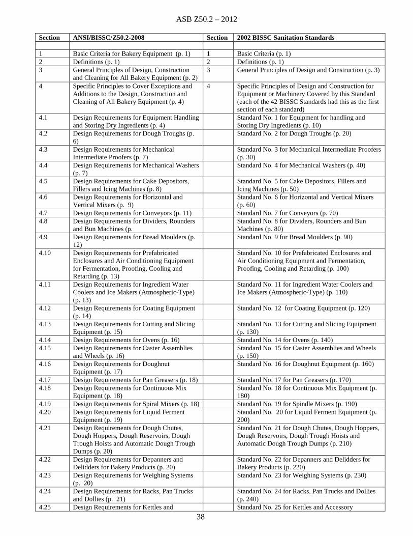
ASB Z50.2 – 2012
38
Section ANSI/BISSC/Z50.2-2008 Section 2002 BISSC Sanitation Standards
1 Basic Criteria for Bakery Equipment (p. 1) 1 Basic Criteria (p. 1)2 Definitions (p. 1) 2 Definitions (p. 1)3 General Principles of Design, Construction
and Cleaning for All Bakery Equipment (p. 2)3 General Principles of Design and Construction (p. 3)
4 Specific Principles to Cover Exceptions andAdditions to the Design, Construction andCleaning of All Bakery Equipment (p. 4)
4 Specific Principles of Design and Construction forEquipment or Machinery Covered by this Standard(each of the 42 BISSC Standards had this as the firstsection of each standard)
4.1 Design Requirements for Equipment Handlingand Storing Dry Ingredients (p. 4)
Standard No. 1 for Equipment for handling andStoring Dry Ingredients (p. 10)
4.2 Design Requirements for Dough Troughs (p.6)
Standard No. 2 for Dough Troughs (p. 20)
4.3 Design Requirements for MechanicalIntermediate Proofers (p. 7)
Standard No. 3 for Mechanical Intermediate Proofers(p. 30)
4.4 Design Requirements for Mechanical Washers(p. 7)
Standard No. 4 for Mechanical Washers (p. 40)
4.5 Design Requirements for Cake Depositors,Fillers and Icing Machines (p. 8)
Standard No. 5 for Cake Depositors, Fillers andIcing Machines (p. 50)
4.6 Design Requirements for Horizontal andVertical Mixers (p. 9)
Standard No. 6 for Horizontal and Vertical Mixers(p. 60)
4.7 Design Requirements for Conveyors (p. 11) Standard No. 7 for Conveyors (p. 70)4.8 Design Requirements for Dividers, Rounders
and Bun Machines (p.Standard No. 8 for Dividers, Rounders and BunMachines (p. 80)
4.9 Design Requirements for Bread Moulders (p.12)
Standard No. 9 for Bread Moulders (p. 90)
4.10 Design Requirements for PrefabricatedEnclosures and Air Conditioning Equipmentfor Fermentation, Proofing, Cooling andRetarding (p. 13)
Standard No. 10 for Prefabricated Enclosures andAir Conditioning Equipment and Fermentation,Proofing, Cooling and Retarding (p. 100)
4.11 Design Requirements for Ingredient WaterCoolers and Ice Makers (Atmospheric-Type)(p. 13)
Standard No. 11 for Ingredient Water Coolers andIce Makers (Atmospheric-Type) (p. 110)
4.12 Design Requirements for Coating Equipment(p. 14)
Standard No. 12 for Coating Equipment (p. 120)
4.13 Design Requirements for Cutting and SlicingEquipment (p. 15)
Standard No. 13 for Cutting and Slicing Equipment(p. 130)
4.14 Design Requirements for Ovens (p. 16) Standard No. 14 for Ovens (p. 140)4.15 Design Requirements for Caster Assemblies
and Wheels (p. 16)Standard No. 15 for Caster Assemblies and Wheels(p. 150)
4.16 Design Requirements for DoughnutEquipment (p. 17)
Standard No. 16 for Doughnut Equipment (p. 160)
4.17 Design Requirements for Pan Greasers (p. 18) Standard No. 17 for Pan Greasers (p. 170)4.18 Design Requirements for Continuous Mix
Equipment (p. 18)Standard No. 18 for Continuous Mix Equipment (p.180)
4.19 Design Requirements for Spiral Mixers (p. 18) Standard No. 19 for Spindle Mixers (p. 190)4.20 Design Requirements for Liquid Ferment
Equipment (p. 19)Standard No. 20 for Liquid Ferment Equipment (p.200)
4.21 Design Requirements for Dough Chutes,Dough Hoppers, Dough Reservoirs, DoughTrough Hoists and Automatic Dough TroughDumps (p. 20)
Standard No. 21 for Dough Chutes, Dough Hoppers,Dough Reservoirs, Dough Trough Hoists andAutomatic Dough Trough Dumps (p. 210)
4.22 Design Requirements for Depanners andDelidders for Bakery Products (p. 20)
Standard No. 22 for Depanners and Delidders forBakery Products (p. 220)
4.23 Design Requirements for Weighing Systems(p. 20)
Standard No. 23 for Weighing Systems (p. 230)
4.24 Design Requirements for Racks, Pan Trucksand Dollies (p. 21)
Standard No. 24 for Racks, Pan Trucks and Dollies(p. 240)
4.25 Design Requirements for Kettles and Standard No. 25 for Kettles and Accessory
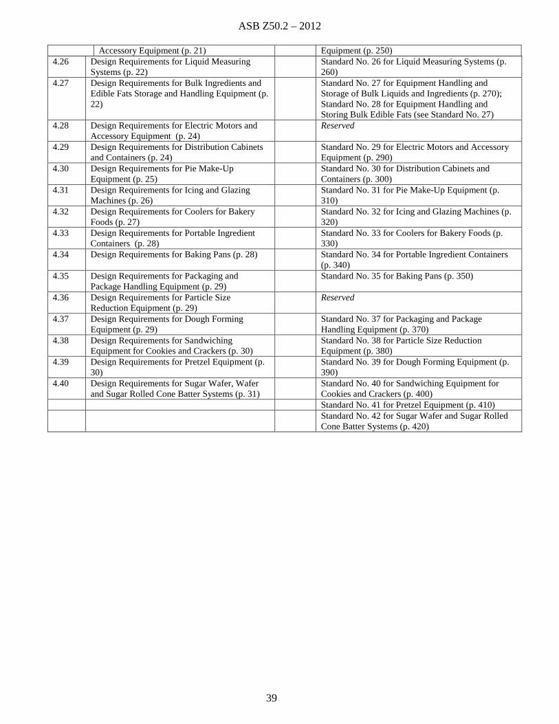
ASB Z50.2 – 2012
39
Accessory Equipment (p. 21) Equipment (p. 250)4.26 Design Requirements for Liquid Measuring
Systems (p. 22)Standard No. 26 for Liquid Measuring Systems (p.260)
4.27 Design Requirements for Bulk Ingredients andEdible Fats Storage and Handling Equipment (p.22)
Standard No. 27 for Equipment Handling andStorage of Bulk Liquids and Ingredients (p. 270);Standard No. 28 for Equipment Handling andStoring Bulk Edible Fats (see Standard No. 27)
4.28 Design Requirements for Electric Motors andAccessory Equipment (p. 24)
Reserved
4.29 Design Requirements for Distribution Cabinetsand Containers (p. 24)
Standard No. 29 for Electric Motors and AccessoryEquipment (p. 290)
4.30 Design Requirements for Pie Make-UpEquipment (p. 25)
Standard No. 30 for Distribution Cabinets andContainers (p. 300)
4.31 Design Requirements for Icing and GlazingMachines (p. 26)
Standard No. 31 for Pie Make-Up Equipment (p.310)
4.32 Design Requirements for Coolers for BakeryFoods (p. 27)
Standard No. 32 for Icing and Glazing Machines (p.320)
4.33 Design Requirements for Portable IngredientContainers (p. 28)
Standard No. 33 for Coolers for Bakery Foods (p.330)
4.34 Design Requirements for Baking Pans (p. 28) Standard No. 34 for Portable Ingredient Containers(p. 340)
4.35 Design Requirements for Packaging andPackage Handling Equipment (p. 29)
Standard No. 35 for Baking Pans (p. 350)
4.36 Design Requirements for Particle SizeReduction Equipment (p. 29)
Reserved
4.37 Design Requirements for Dough FormingEquipment (p. 29)
Standard No. 37 for Packaging and PackageHandling Equipment (p. 370)
4.38 Design Requirements for SandwichingEquipment for Cookies and Crackers (p. 30)
Standard No. 38 for Particle Size ReductionEquipment (p. 380)
4.39 Design Requirements for Pretzel Equipment (p.30)
Standard No. 39 for Dough Forming Equipment (p.390)
4.40 Design Requirements for Sugar Wafer, Waferand Sugar Rolled Cone Batter Systems (p. 31)
Standard No. 40 for Sandwiching Equipment forCookies and Crackers (p. 400)Standard No. 41 for Pretzel Equipment (p. 410)Standard No. 42 for Sugar Wafer and Sugar RolledCone Batter Systems (p. 420)