Embed Size (px)
Citation preview

Effect of Low-Earth Orbit Space Environment on Structural Mechanics of a Deployable Membrane Space Antenna
Johanne C. Heald* and Xin-Xiang Jiang†
Spacecraft Engineering Directorate, Canadian Space Agency, Montréal, Québec, Canada J3Y 8Y9
This paper presents an investigation into the properties of membrane structures for space-based antenna applications when subjected to the space environment. Various analytical and experimental activities that have been undertaken at the early phase of development of a multi-layer, deployable membrane structure are outlined. The membranes described here are prototypes for the development of a possible on-orbit flight experiment in thin structure deployment, where such an experiment addresses necessary questions related to the use of this technology for membrane synthetic aperture radar. Several candidate polyimide materials are being investigated as a possible substrate structure for the crystalline electronic components that the antenna must support. Included among these materials are polyimide film materials, as well as liquid crystal polymer (LCP) braided substrates. Early experimental results indicate that Kapton materials have adverse reactions to the space environment, and this paper provides data detailing how material degradations are linked to structural properties. Experiments detailed here have used a space environment simulation apparatus and a Dynamic Mechanical Analyzer to examine the elastic and microplastic behaviour of the membrane material after exposure to atomic oxygen and vacuum ultraviolet radiation. Two types of thin film polymer material are considered as possible membrane structures for antenna applications, as well as a braided LCP material. The goal of this investigation is to be able to better predict the flatness variations that would result from the folding and stowage of the structure, and then deployment of the membrane in space environment.
* Structures Research Scientist, Space Structures Group, AIAA Member. † Space Environment Research Scientist, Thermal and Materials Group. © Government of Canada, 2007
American Institute of Aeronautics and Astronautics
1
48th AIAA/ASME/ASCE/AHS/ASC Structures, Structural Dynamics, and Materials Conference<br> 15th23 - 26 April 2007, Honolulu, Hawaii
AIAA 2007-2181
Copyright © 2007 by Government of Canada. Published by the American Institute of Aeronautics and Astronautics, Inc., with permission.
I. Introduction HILE there has been a great deal of discussion in the past few years about the challenges posed by membrane structures in space, that discussion has centred on a limited number of design concerns. The characterization of basic mechanical properties of the thin films membranes has been neglected in favour of
issues such as membrane wrinkling and deployment of the flexible structure. The membrane sunshield of the James Webb Space Telescope1 (JWST) was the application that was driving much of the research in membrane wrinkling. Given the design of a deployment system that loaded the JWST sunshield boundary, the consideration of stiffness losses, the required nonlinear numerical modeling, and the non-uniform heating of a membrane structure due to wrinkling at membrane corners were all timely issues. However, there are other architectures that could make use of membrane structures that do not have the same boundary constraints. Particularly, for science applications in which the membrane structure supports data collection devices, the accuracy and stability of the membrane structure is integral to the accuracy of scientific data. Using membrane structures as an inseparable part of a scientific instrument, with more design choices available in the boundary conditions, requires that membrane mechanical and material properties be examined more closely.
W
The Canadian Space Agency (CSA) is currently studying several applications that might make use of thin-film membrane structures. These applications include antennae for sea-surface height altimeters and C-band antennae for synthetic aperture radar (SAR) used in low-Earth or planetary orbit.2 Multiple membrane layers would be required in order to support an antenna radiator plane physically separate from its feed network and ground plane. Additional multi-layer insulation (MLI) and shielding layers would likely also be required. Polymer materials Kapton E or HN, Pyralux AP, and Liquid Crystal Polymer (LCP) are the candidates being considered for the thin-film membrane antenna structure. These thin-film materials would then be non-uniformly coated with crystalline materials such as copper to support the function of the membrane instrument. In order to have confidence in the launch stowage, on-orbit deployment, and long-term electrical performance of such antennae, the structural behaviour and material properties of the membrane providing the instrument support must be known. Very few of the mechanical properties of membranes have been verified experimentally. Several different methods of modeling membrane structures as two-dimensional continua in tension3-5 and as thin shells with non-zero bending stiffness,6 have been proposed as ways of tackling the problem numerically. These methods were introduced and developed specifically in order to address the varied stress states of partially wrinkled and partially taut membranes. Experimental work on membrane structures has focused on macroscopic behaviour, examining wrinkle amplitude and area under varied loading conditions7,8 quantifying dynamic behaviour9 and determining deployed shape accuracy.10 Recently at the Canadian Space Agency, there has been some work done in identifying characteristics of membrane materials, particularly for Kapton HN.11 However, there has been little work on the influence of the space environment on membrane material degradations published, and until now, no work at all on how changes to the material will influence the behaviour of the structure. This paper examines some of the fundamental issues involved in membrane mechanics. The elastic and plastic nature of the membrane is explored using samples of the three different membrane materials, some with copper coating, others without. These materials have experienced varying degrees of exposure to the space environment. The results are compared to previous work and to current models, and the effect of nonlinearities is examined for the stowage and subsequent deployment of membranes for space applications.
II. Membrane Prototype Development at the Canadian Space Agency Canada has developed an expertise in Synthetic Aperture Radar antenna, and it is from this expertise that
Canada's interest in membrane antennae stems. This experience is based on rigid-panel SAR, however, and synthetic aperture radar has several requirements that complicate the design of a membrane structure to replace the rigid panel. First, a SAR antenna must be large in order to obtain the required accuracy. Plans for a future membrane antenna have fluxuated in terms of size, always on the order of meters or tens of meters. The current design calls for a membrane of the order of approximately 4 m by 10 m, which would need to be deployed and then held in tension on-orbit. Secondly, the requirement on the level of flatness of the membrane is rather stringent, on the order of a maximum of a few millimeters of out-of-plane deflection for a C-band antenna. This flatness has to
American Institute of Aeronautics and Astronautics
2
be maintained despite thermal cycles, vibrations, membrane stress relaxation, or creasing of the membrane. Thirdly, the dimensional stability of the membrane is also critical, since the locations of electrical elements on the membrane cannot be allowed to physically drift from one another if the membrane were to undergo stress relaxation or a change in properties over time. It is this quality of stability of the membrane over time that is addressed by the examinations of the effects of the space environment in the current paper.
As the Canadian Space Agency is still in the early stages of its research into membrane structures technology, it wishes to judge the suitability of these structures for Synthetic Aperture Radar, as well as determine the technical difficulties involved in their use. While the CSA has developed a variety of membrane mock-ups and scale research models in the past,12 it has no experience with a fully and autonomously deployable prototype. For these reasons, the CSA is currently developing its first deployable membrane structure prototype in-house, which is described in detail in an accompanying paper.13 The material to be used in the membrane prototype has not yet been selected, and it is expected that this decision will rest on both mechanical considerations such as those presented in this paper and the electrical considerations described elsewhere.2
The current prototype of a SAR membrane antenna in C-band being developed at the Canadian Space Agency is sized at a quarter-scale of the full structure required in space. It calls for 2 to 5 membrane layers, interconnected with copper-coated membrane material carrying electrical signals from one layer to another. Layers distributing the power will be almost completely covered with copper, whereas layers carrying only the radiating elements will only be sparsely covered. Several separate layers of membrane have to be tensioned and kept at a constant distance from each other. The amount of copper on each of these layers is different and the membranes will not only be subjected to different thermal environments, with some layers exposed to the sun while others are at least partially hidden from it, but the varying amount of crystalline material will cause each membrane layer to react differently. The candidate materials being considered for the membrane prototype are thus being examined both with copper coating and without at this point. The results presented here are thus crucial to future CSA decisions concerning membrane structures.
III. Membrane Exposure to the Space Environment
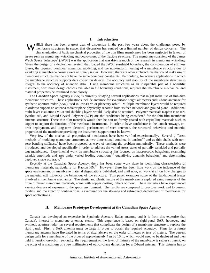
The long-term survivability of a membrane SAR antenna in the harsh space environment is one of biggest challenges of this technology,14,15 given the fact that the candidate substrate materials are mostly polymers. A review of the literature has revealed very limited data on the stability of the mechanical performance of such thin film materials in the space environment because those researchers doing the testing have been mainly concerned with the film's thermo-optical properties. The study by Stuckey et al.,15 however, indicates that space radiation, primarily in the vacuum ultra-violet (VUV), can result in a degradation in mechanical properties. It is generally thought that erosion of thin film materials by atomic oxygen will result in possible degradation in mechanical performance. However, no research has been reported on the effect of
atomic oxygen erosion on mechanical performance of these thin films.
Figure 1. Space simulation apparatus used for atomic oxygengeneration
American Institute of Aeronautics and Astronautics
3
An atomic oxygen exposure experiment on Kapton E was performed using the Canadian Space Agency's space simulation apparatus, as shown in Figure 1. It is an RF plasma-based atomic oxygen generator. Vacuum is generated using a Danielson Tribodyn 200/57 three-module molecular drag pump, with a typical operating pressure at ~100 mTorr inside the test chamber for atomic oxygen flux production. Before the introduction of oxygen for producing atomic oxygen, a pressure on the order of 10-4 Torr was achieved. The oxygen flow rate was set to 15 cc/m. Previous experiments on the characterization of this facility indicated that the atomic oxygen source is approximately of an energy level of 0.1 eV.16
0
1
2
3
4
5
6
-0.3 -0.2 -0.1 0 0.1 0.2
Strain (%)
Stre
ss (M
Pa)
Stress (Mpa) atRT90 C
120 C
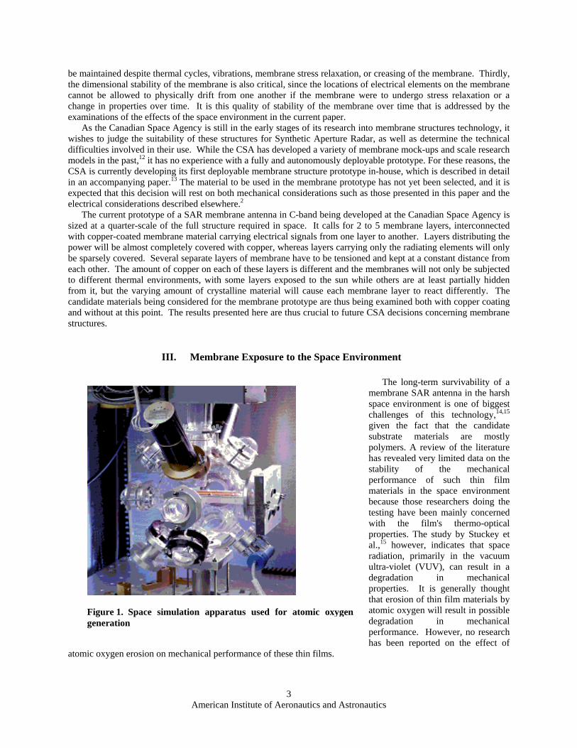
Figure 2. Stress-strain curves of Kapton E prior to atomic oxygenexposure
Round thin film samples of 2 cm diameter were used in the atomic oxygen exposure experiment. The effective atomic oxygen fluence for the experiment was determined using standard witness samples of Kapton HN, in accordance with ASTM Standard E 2089-00.17 Each Kapton E sample was exposed to an equivalent of 3 years in the low-Earth orbit (LEO) space environment. The recession in the thickness of the exposed film was measured to be approximately 0.006 mm (6 microns) on average, and it should be noted that this recession was not uniform across the exposed sample. The samples were then cut into samples 6.5 mm by 30 mm that could be accomodated in the test section of a DMA 2980 instrument. The mechanical performance of the films before and after atomic
oxygen exposure was then measured by determining primarily the Young's Modulus and the strain-stress curve.
Figure 2 shows the strain-stress curves for Kapton E at three different temperatures before atomic oxygen exposure. Note that 'RT' indicates testing at 'room temperature'. The estimated elastic modulus is 4.8 GPa, which is close to what is published by the manufacturer, Dupont, according to their data sheets for this material.18
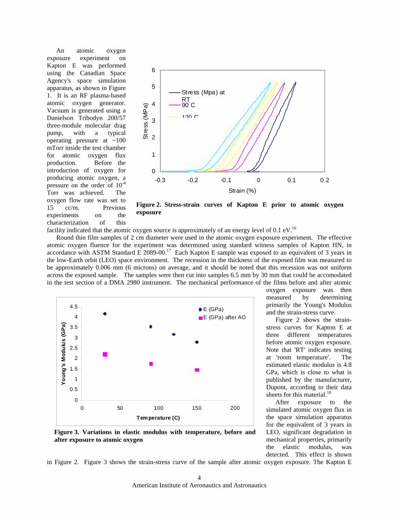
After exposure to the simulated atomic oxygen flux in the space simulation apparatus for the equivalent of 3 years in LEO, significant degradation in mechanical properties, primarily the elastic modulus, was detected. This effect is shown
in Figure 2. Figure 3 shows the strain-stress curve of the sample after atomic oxygen exposure. The Kapton E
0
0.5
1
1.5
2
2.5
3
3.5
4
4.5
0 50 100 150 200
Temperature (C)
Yo
ung
's M
odu
lus
(GP
a)
E (GPa)E (GPa) after AO
Figure 3. Variations in elastic modulus with temperature, before andafter exposure to atomic oxygen
American Institute of Aeronautics and Astronautics
4
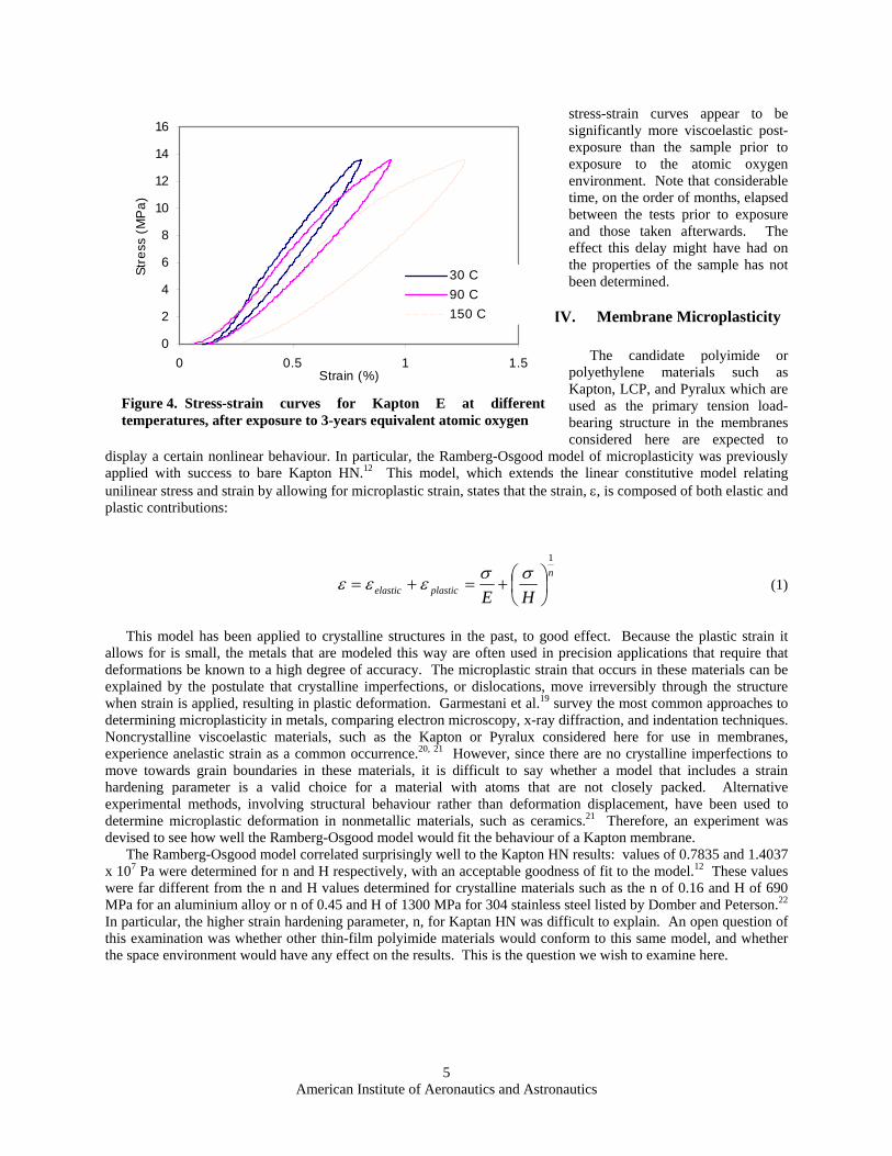
stress-strain curves appear to be significantly more viscoelastic post-exposure than the sample prior to exposure to the atomic oxygen environment. Note that considerable time, on the order of months, elapsed between the tests prior to exposure and those taken afterwards. The effect this delay might have had on the properties of the sample has not been determined.
IV. Membrane Microplasticity The candidate polyimide or
polyethylene materials such as Kapton, LCP, and Pyralux which are used as the primary tension load-bearing structure in the membranes considered here are expected to
display a certain nonlinear behaviour. In particular, the Ramberg-Osgood model of microplasticity was previously applied with success to bare Kapton HN.12 This model, which extends the linear constitutive model relating unilinear stress and strain by allowing for microplastic strain, states that the strain, ε, is composed of both elastic and plastic contributions:
0
2
4
6
8
10
12
14
16
0 0.5 1 1Strain (%)
Stre
ss (
MP
a)
.5
30 C90 C150 C
Figure 4. Stress-strain curves for Kapton E at differenttemperatures, after exposure to 3-years equivalent atomic oxygen
n
plasticelastic HE
1
⎟⎠⎞
⎜⎝⎛+=+=σσεεε (1)
This model has been applied to crystalline structures in the past, to good effect. Because the plastic strain it allows for is small, the metals that are modeled this way are often used in precision applications that require that deformations be known to a high degree of accuracy. The microplastic strain that occurs in these materials can be explained by the postulate that crystalline imperfections, or dislocations, move irreversibly through the structure when strain is applied, resulting in plastic deformation. Garmestani et al.19 survey the most common approaches to determining microplasticity in metals, comparing electron microscopy, x-ray diffraction, and indentation techniques. Noncrystalline viscoelastic materials, such as the Kapton or Pyralux considered here for use in membranes, experience anelastic strain as a common occurrence.20, 21 However, since there are no crystalline imperfections to move towards grain boundaries in these materials, it is difficult to say whether a model that includes a strain hardening parameter is a valid choice for a material with atoms that are not closely packed. Alternative experimental methods, involving structural behaviour rather than deformation displacement, have been used to determine microplastic deformation in nonmetallic materials, such as ceramics.21 Therefore, an experiment was devised to see how well the Ramberg-Osgood model would fit the behaviour of a Kapton membrane.
The Ramberg-Osgood model correlated surprisingly well to the Kapton HN results: values of 0.7835 and 1.4037 x 10⁷ Pa were determined for n and H respectively, with an acceptable goodness of fit to the model.12 These values were far different from the n and H values determined for crystalline materials such as the n of 0.16 and H of 690 MPa for an aluminium alloy or n of 0.45 and H of 1300 MPa for 304 stainless steel listed by Domber and Peterson.22 In particular, the higher strain hardening parameter, n, for Kaptan HN was difficult to explain. An open question of this examination was whether other thin-film polyimide materials would conform to this same model, and whether the space environment would have any effect on the results. This is the question we wish to examine here.
American Institute of Aeronautics and Astronautics
5
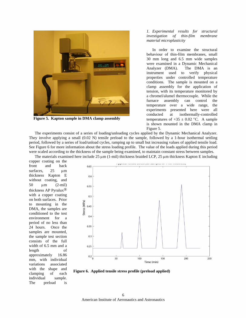
1. Experimental results for structural investigation of thin-film membrane material microplasticity
In order to examine the structural
behaviour of thin-film membranes, small 30 mm long and 6.5 mm wide samples were examined in a Dynamic Mechanical Analyzer (DMA). The DMA is an instrument used to verify physical properties under controlled temperature conditions. The sample is mounted on a clamp assembly for the application of tension, with its temperature monitored by a chromel/alumel thermocouple. While the furnace assembly can control the temperature over a wide range, the experiments presented here were all conducted at isothermally-controlled temperatures of +35 ± 0.02 °C. A sample is shown mounted in the DMA clamp in Figure 5.
The experiments consist of a series of loading/unloading cycles applied by the Dynamic Mechanical Analyzer. They involve applying a small (0.02 N) tensile preload to the sample, followed by a 1-hour isothermal settling period, followed by a series of load/unload cycles, ramping up to small but increasing values of applied tensile load. See Figure 6 for more information about the stress loading profile. The value of the loads applied during this period were scaled according to the thickness of the sample being examined, to maintain constant stress between samples.
Figure 5. Kapton sample in DMA clamp assembly
The materials examined here include 25 μm (1-mil) thickness braided LCP, 25 μm thickness Kapton E including copper coating on the front and back surfaces, 25 μm thickness Kapton E without coating, and 50 μm (2-mil) thickness AP Pyralux® with a copper coating on both surfaces. Prior to mounting in the DMA, the samples are conditioned to the test environment for a period of no less than 24 hours. Once the samples are mounted, the sample test section consists of the full width of 6.5 mm and a length of approximately 16.86 mm, with individual variations associated with the shape and clamping of each individual sample. The preload is
Figure 6. Applied tensile stress profile (preload applied)
American Institute of Aeronautics and Astronautics
6
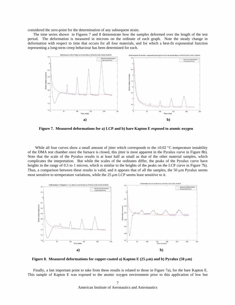
considered the zero-point for the determination of any subsequent strain. The time series shown in Figures 7 and 8 demonstrate how the samples deformed over the length of the test
period. The deformation is measured in microns on the ordinate of each graph. Note the steady change in deformation with respect to time that occurs for all four materials, and for which a best-fit exponential function representing a long-term creep behaviour has been determined for each.
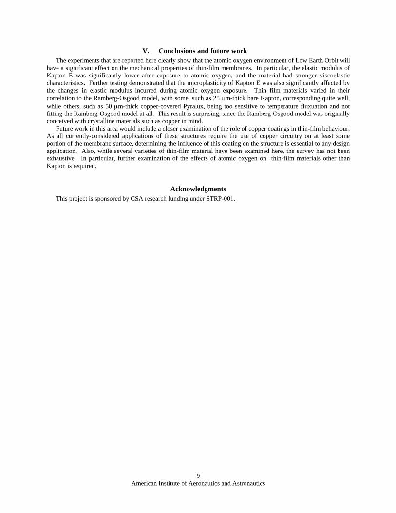
While all four curves show a small amount of jitter which corresponds to the ±0.02 °C temperature instability
of the DMA test chamber once the furnace is closed, this jitter is most apparent in the Pyralux curve in Figure 8b). Note that the scale of the Pyralux results is at least half as small as that of the other material samples, which complicates the intepretation. But while the scales of the ordinates differ, the peaks of the Pyralux curve have heights in the range of 0.5 to 1 micron, which is similar to the heights of the peaks on the LCP curve in Figure 7b). Thus, a comparison between these results is valid, and it appears that of all the samples, the 50 μm Pyralux seems most sensitive to termperature variations, while the 25 μm LCP seems least sensitive to it.
a) b)
Figure 7. Measured deformations for a) LCP and b) bare Kapton E exposed to atomic oxygen
a) b)
Figure 8. Measured deformations for copper-coated a) Kapton E (25 μm) and b) Pyralux (50 μm)
Finally, a last important point to take from these results is related to those in Figure 7a), for the bare Kapton E. This sample of Kapton E was exposed to the atomic oxygen environment prior to this application of low but
American Institute of Aeronautics and Astronautics
7

cyclically increasing stresses. As seen in Figure 3 in a previous section of this paper, the elastic modulus will have decreased several-fold due to exposure to atomic oxygen. When compared to the other materials, the deformation of the Kapton E seems to have similar magnitude to that of those other materials tested here. However, the deformations of Kapton E are smaller by an order of magnitude than those obtained in previous testing on Kapton HN for the same applied loads. Dupont specifies a modulus twice as high for Kapton E (780 Kpsi) than for Kapton HN (370 Kpsi).18,23 Allowing for this difference in the as-manufactured modulus only explains about one half of the variation between the two materials. The decrease in modulus due to atomic oxygen exposure must account for the variation that remains.
In order to determine the values corresponding to a Ramberg-Osgood model for the Kapton E exposed to the space enivonment, the plastic strain must be measured at each level of applied stress. In Figure 7b), the cycles are of increasing strain measured for each stress magnitude, with plastic strain measured as the distance between initial and final strain at zero load (where zero load represents the state in which only the tensile preload is applied). These plastic strains are then graphed against applied stresses in log-log space in Figure 9. A best-fit line on this plot determines the Ramberg-Osgood parameters. In this case, n = 0.2051 and H = 4.8365 x 10⁹ Pa. In comparison with the values previously found for Kapton HN that was never exposed to the space environment, the work hardening parameter n has decreased significantly, while the H parameter is significantly higher.
Figure 9. Ramberg-Osgood model fit to Kapton E microplastic strain
Similar work was done to determine the values of these parameters for each of the different materials examined here. The resulting values of n and H can be found in Table 1, along with those values for the previously-tested Kapton HN mentioned here for comparison. It is interesting to note that the parameters for copper-covered Kapton E that was not exposed to the space environment more closely resemble the parameters for Kapton HN than those of bare Kapton E after exposure to atomic oxygen, despite the changes in material properties introduced by the addition of copper coating. It was impossible to determine the microplastic strain for the 50 μm-thick Pyralux sample due to the data sensitivity to temperature variations and therefore, it was not possible to fit that data to the Ramberg-Osgood model.
Table 1. Ramberg-Osgood parameters for 25 μm-thickness film materials Material n H (MPa) Kapton HN1 0.7835 14.037 Kapton E, exposed to atomic O
0.2051 4834.5
Kapton E + Cu 0.2528 10.5465 LCP 0.3408 28909
American Institute of Aeronautics and Astronautics
8
V. Conclusions and future work The experiments that are reported here clearly show that the atomic oxygen environment of Low Earth Orbit will
have a significant effect on the mechanical properties of thin-film membranes. In particular, the elastic modulus of Kapton E was significantly lower after exposure to atomic oxygen, and the material had stronger viscoelastic characteristics. Further testing demonstrated that the microplasticity of Kapton E was also significantly affected by the changes in elastic modulus incurred during atomic oxygen exposure. Thin film materials varied in their correlation to the Ramberg-Osgood model, with some, such as 25 μm-thick bare Kapton, corresponding quite well, while others, such as 50 μm-thick copper-covered Pyralux, being too sensitive to temperature fluxuation and not fitting the Ramberg-Osgood model at all. This result is surprising, since the Ramberg-Osgood model was originally conceived with crystalline materials such as copper in mind.
Future work in this area would include a closer examination of the role of copper coatings in thin-film behaviour. As all currently-considered applications of these structures require the use of copper circuitry on at least some portion of the membrane surface, determining the influence of this coating on the structure is essential to any design application. Also, while several varieties of thin-film material have been examined here, the survey has not been exhaustive. In particular, further examination of the effects of atomic oxygen on thin-film materials other than Kapton is required.
Acknowledgments This project is sponsored by CSA research funding under STRP-001.
American Institute of Aeronautics and Astronautics
9

References 1Pacini, Linda, Lou, Michael, Johnston, John, and Lienard, Sebatien. "Sunshield Technology and Flight Experiment for the
Next Generation Space Telescope," UV, Optical, and IR Space Telescopes and Instruments, Proc. of, SPIE Vol. 4013, 2000, pp. 884-893.
2Colinas, J., Potvin, M.J., Jiang, X.X., Girard, R., Tremblay, G., and Cascarano, B. “Recent developments on C-band membrane antennas for small-satellites applications,” Proceedings of the 28th ESA Antenna Workshop on Space Antenna Systems and Technologies, Noordjwik, Holland, May 31-June 4, 2005.
3Miller, R. K. and Hedgepeth, J. M. “An Algorithm for Finite Element Analysis of Partially Wrinkled Membranes,” AIAA Journal, Vol. 20, No. 12, 1982, pp. 1761-1763.
4Adler, Aaron L., Mikulas, Martin M., and Hedgepeth, John M. “Static and Dynamic Analysis of Partially Wrinkled Membrane Structures,” 41st AIAA/ASME/ASCE/AHS/ASC Structures, Structural Dynamics, and Materials Conference, AIAA 2000-1810, Atlanta, GA, 2000.
5Ding, Hongli, Yang, Bingen, Lou, Michael, and Fang, Houfei. “New Numerical Method for Two-Dimensional Partially Wrinkled Membranes,” AIAA Journal, Vol. 41, No. 1, 2003, pp. 125-132.
6Tessler, Alexander, Sleight, David W., and Wang, John T. “Nonlinear Shell Modeling of Thin Membranes with Emphasis on Structural Wrinkling,” 44th AIAA/ASME/ASCE/AHS/ASC Structures, Structural Dynamics and Materials Conference, AIAA 2003-1931, Norfolk, VA, 2003.
7Blandino, J.R., Johnston, J.D., Miles, J.J. and Soplop, J.S. ‘Thin Film Membrane Wrinkling due to Mechanical and Thermal Loads,’ 42nd AIAA/ASME/ASCE/AHS/ASC Structures, Structural Dynamics and Materials Conference, AIAA 2001-1345, Seattle, WA, 2001.
8Narusawa, Yasutaka, Aoki, Takahira, Nakasuka, Shinichi, and Motohashi, Satomi. "Behavior of Membrane Structures under Microgravity Environment," Proceedings of the Twenty-First International Symposium on Space Technology and Science, Omiya, Japan, 1998, pp. 428-433.
9Jones, Thomas W., Dorrington, Adrian A., Shortis, Mark R., and Hendricks, Aron R. "Validation of Laser-Induced Flurescent Photogrammetric Targets on Membrane Structures," 45th AIAA/ASME/ASCE/AHS/ASC Structures, Structural Dynamics and Materials Conference, AIAA 2004-1663, Palm Springs, CA, 2004.
10Maji, A.K. and Starnes, M.A. "Shape Measurement and Control of Deployable Membrane Structures," Experimental Mechanics, Vol. 40, No. 2, 2000, pp. 154-159.
11Heald, J.C. and Potvin, M.-J. "Experimental Mechanics of a Wrinkled Multi-Layer Deployable Membrane Space Antenna," 47th AIAA/ASME/ASCE/AHS/ASC Structures, Structural Dyanmics, and Materials Conference, AIAA 2006-1605, Newport, RI, 2006.
12Heald, J.C., Potvin, M.-J., and Jiang, X.-X., "Experimental Investigations to Support a Multi-Layer Deployable Membrane Structure for Space Antennae," 46th AIAA/ASME/ASCE/AHS/ASC Structures, Structural Dynamics, and Materials Conference, AIAA 2005-2317, Austin, TX, Apr. 2005.
13Shen, Yu, Montminy, Steeve, and Zheng, Wanping. "Large SAR Membrane Antenna Deployable Structure Design and Dynamic Simulation," 48th AIAA/ASME/ASCE/AHS/ASC Structures, Structural Dynamics and Materials Conference, Honolulu, HI, Apr. 2007.
14Huang, John; "The Development of Inflatable Array Antenna"; IEEE Antennas and Propagation Magazine, Vol. 43, No. 4, August 2001, pp. 44-50.
15Stuckey, W. K, M. J Meshishnek, W. D Hanna and F. D. Ross, "Space environment test of materials for inflatable structures", Aerospace Report No:TR-98(1055)-1, Aerospace Corporation, California, April 1998.
16Lucier, L., X. Jiang & D. Nikanpour, “Atomic oxygen degradation study of a candidate retroreflective target material for Space Vision System”, Proceeding of 4th International Symposium of Environment Test for Space Program, Belgium, 12-13 June 2001.
17American Society for Testing and Materials Standards (ASTM), “Standard Practices for Ground Laboratory Atomic Oxygen Interaction Evaluation of Materials for Space Applications,” Designation E 2089-00, June, 2000.
18Dupont Technical Information, "Kapton® E high modulus polyimide film", DuPont High Performance Materials, DuPont Road, Circleville, OH 43113.
19Garmestani, H., Harris, K., and Lourenco, L. “A Novel Microcharacterisation Technique in the Measurement of Strain and Orientation Gradient in Advanced Materials,” NASA University Research Centers Technical Advances in Education, Aeronautics, Space, Autonomy, Earth and Environment, Volume 1, pp. 931-936, 1997.
20Marschall, Charles W. and Maringer, Robert E. Dimensional Instability: an introduction, Pergamon Press Ltd., Bath, U.K., 1977, Chaps. 1-5.
21Ogawa, Hiroyuki, Nishino, Yoichi, and Asano, Shigeru. “Internal Friction and Microplasticity of Carbon-Fiber-Reinforced SiC Ceramics,” J. Japan. Inst. Metals, Vol. 59, No. 8, 1995, pp. 788-792.
22Domber, Jeanette L., and Peterson, Lee D. "Implications of Material Microyield for Gossamer Optical Reflectors," 43rd AIAA/ASME/ASCE/AHS/ASC Structures, Structural Dynamics and Materials Conference, AIAA 2002-1503, Denver, CO, 2002.
23Dupont Technical Information, "DuPontTM Kapton® HN polyimide film", DuPont High Performance Materials, DuPont Road, Circleville, OH 43113.
American Institute of Aeronautics and Astronautics
10