Embed Size (px)
Citation preview
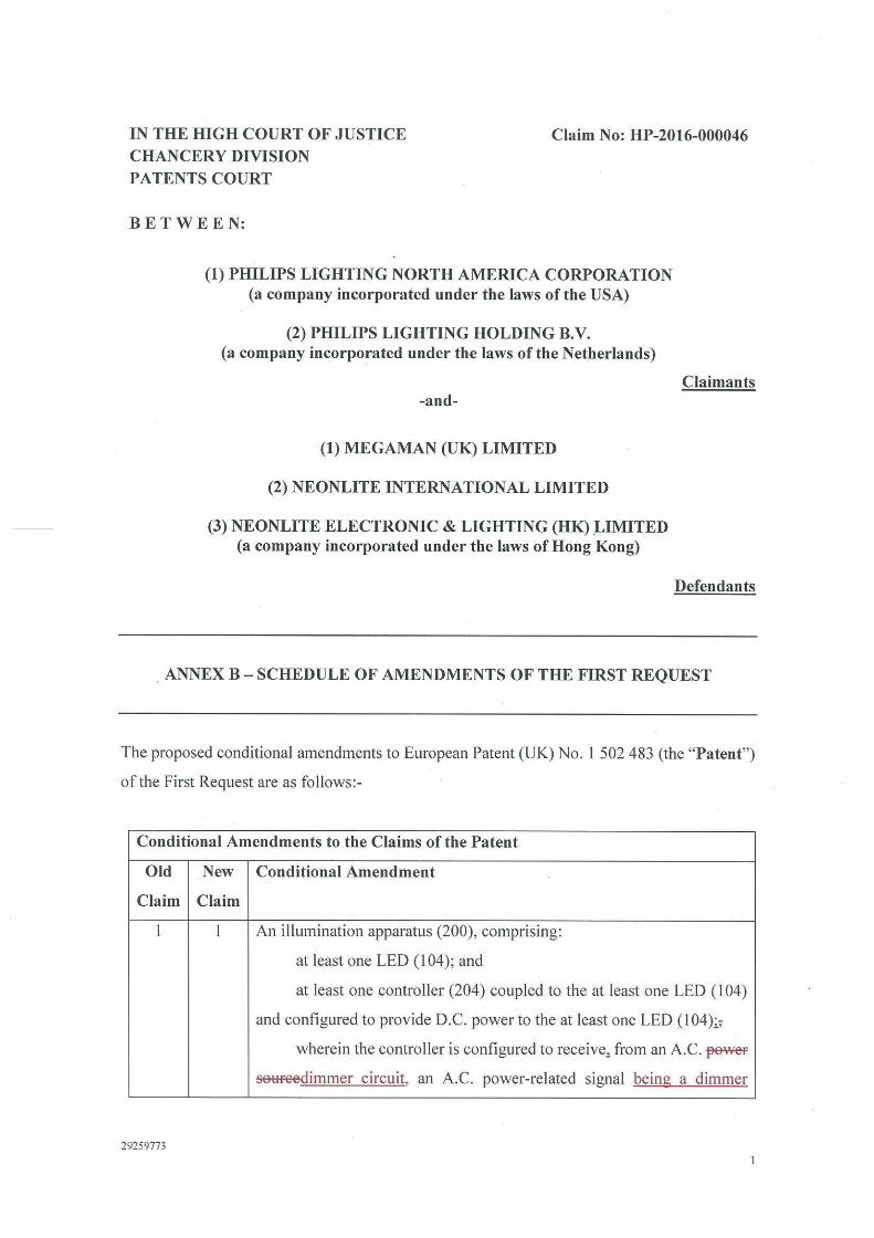
IN THE HIGH COURT OF JUSTICE CHANCERY DIVISION
Claim No: HP-2016-000046
PATENTS COURT
BETWEEN:
(1) PHILIPS LIGHTING NORTH AMERICA CORPORATION (a company incorporated under the laws of the USA)
(2) PHILIPS LIGHTING HOLDING B.V. (a company incorporated under the laws of the Netherlands)
-and-
(1) MEGAMAN (UK) LIMITED
(2) NEONLITE INTERNATIONAL LIMITED
(3) NEONLITE ELECTRONIC & LIGHTING (HK) _LIMITED (a company incorporated under the laws of Hong Kong)
Claimants
Defendants
. ANNEX B - SCHEDULE OF AMENDMENTS OF THE FIRST REQUEST
The proposed conditional amendments to European Patent (UK) No. 1 502 483 (the "Patent")
of the First Request are as follows:-
Conditional Amendments to the Claims of the Patent
Old New Conditional Amendment
Claim Claim
l l An illumination apparatus (200), comprising:
at least one LED (104); and
at least one controller (204) coupled to the at least one LED (104)
and configured to provide D.C. power to the at least one LED (104);;
wherein the controller is configured to receive., from an A.C. ~
setiFeedimmer circuit, an A.C. power-related signal being a dimmer
29259773
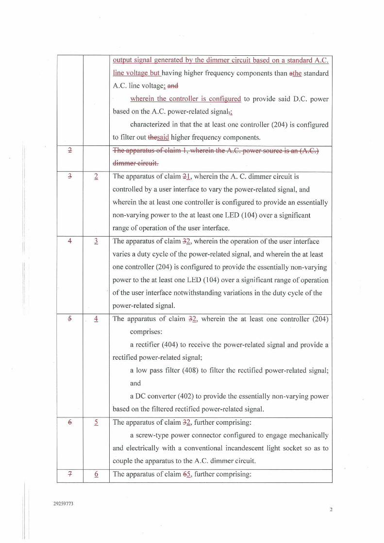
outgut signal generated by the dimmer circuit based on a standard A.C.
line voltage but having higher frequency components than athe standard
A.C. line voltage; aR€I-
wherein the controller is configured to provide said D.C. power
based on the A.C. power-related signal,;
characterized in that the at least one controller (204) is configured
to filter out thesaid higher frequency components.
l The apparattts of elairn l , wherein the A.G. po·wer sottree is an (A.G.)
Elirnrner eirettit.
J. 2. The apparatus of claim ll, wherein the A. C. dimmer circuit is
controlled by a user interface to vary the power-related signal, and
wherein the at least one controller is configured to provide an essentially
non-varying power to the at least one LED (104) over a significant
range of operation of the user interface.
II 4 l The apparatus of claim J-2_, wherein the operation of the user interface
varies a duty cycle of the power-related signal, and wherein the at least
one controller (204) is configured to provide the essentially non-varying
power to the at least one LED ( I 04) over a significant range of operation
of the user interface notwithstanding variations in the duty cycle of the
power-related signal.
~ 1 The apparatus of claim J-2_, wherein the at least one controller (204)
comprises:
a rectifier ( 404) to receive the power-related signal and provide a
rectified power-related signal;
a low pass filter ( 408) to filter the rectified power-related signal;
and
a DC converter ( 402) to provide the essentially non-varying power
based on the filtered rectified power-related signal.
6 2 The apparatus of claim J-2_, further comprising:
a screw-type power connector configured to engage mechanically
and electrically with a conventional incandescent light socket so as to
couple the apparatus to the A.C. dimmer circuit.
+ Q The apparatus of claim 61, further comprising:
29259773 2
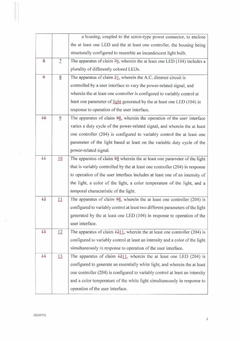
a housing, coupled to the screw-type power connector, to enclose
the at least one LED and the at least one controller, the housing being
structurally configured to resemble an incandescent light bulb.
& 1 The apparatus of claim +Q, wherein the at least one LED ( I 04) includes a
plurality of differently colored LEDs.
9 ~ The apparatus of claim ;!-1, wherein the A.C. dimmer circuit is
controlled by a user interface to vary the power-related signal , and
wherein the at least one controller is configured to variably control at
least one parameter of light generated by the at least one LED (104) in
response to operation of the user interface.
+o 2 The apparatus of claim 9~, wherein the operation of the user interface
varies a duty cycle of the power-related signal, and wherein the at least
one controller (204) is configured to variably control the at least one
parameter of the light based at least on the variable duty cycle of the
power-related signal.
++ lQ The apparatus of claim 9~ wherein the at least one parameter of the light
that is variably controlled by the at least one controller (204) in response
to operation of the user interface includes at least one of an intensity of
the light, a color of the light, a color temperature of the light, and a
temporal characteristic of the light.
~ 11 The apparatus of claim 9~, wherein the at least one controller (204) is
configured to variably control at least two different parameters of the light
generated by the at least one LED ( 104) in response to operation of the
user interface.
.g ll The apparatus of claim ~ll, wherein the at least one controller (204) is
configured to variably control at least an intensity and a color of the light
simultaneously in response to operation of the user interface.
+4 11 The apparatus of claim ~ll, wherein the at least one LED (204) is
configured to generate an essentially white light, and wherein the at least
one controller (204) is configured to variably control at least an intensity
and a color temperature of the white light simultaneously in response to
operation of the user interface.
29259773 3
l1
19
29259773
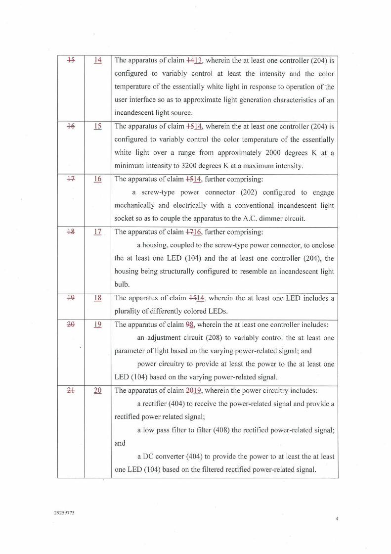
The apparatus of claim +4.Ll., wherein the at least one controller (204) is
configured to variably control at least the intensity and the color
temperature of the essentially white light in response to operation of the
user interface so as to approximate light generation characteristics of an
incandescent light source.
The apparatus of claim -1:-§.11., wherein the at least one controller (204) is
configured to variably control the color temperature of the essentially
white light over a range from approximately 2000 degrees K at a
minimum intensity to 3200 degrees Kata maximum intensity.
The apparatus of claim -1:-§. 14, further comprising:
a screw-type power connector (202) configured to engage
mechanically and electrically with a conventional incandescent light
socket so as to couple the apparatus to the A.C. dimmer circuit.
The apparatus of claim ++I 6, further comprising:
a housing, coupled to the screw-type power connector, to enclose
the at least one LED ( 104) and the at least one contra Iler (204 ), the
housing being structurally configured to resemble an incandescent light
bulb.
The apparatus of claim -1:-§.11., wherein the at least one LED includes a
plurality of differently colored LEDs.
The apparatus of claim 9~, wherein the at least one controller includes:
an adjustment circuit (208) to variably control the at least one
parameter of light based on the varying power-related signal; and
power circuitry to provide at least the power to the at least one
LED (104) based on the varying power-related signal.
The apparatus of claim 201.2., wherein the power circuitry includes:
a rectifier ( 404) to receive the power-related signal and provide a
rectified power related signal;
a low pass filter to filter (408) the rectified power-related signal ;
and
a DC converter (404) to provide the power to at least the at least
one LED (104) based on the filtered rectified power-related signal.
4

~ 21 The apparatus of claim U20, wherein the adjustment circuit is coupled to
the DC converter and is configured to variably control the at least one
LED ( 104) based on the filtered rectified power-related signal.
u 22 The apparatus of claim U20, wherein the adjustment circuit includes at
least one processor ( 102) configured to monitor at least one of the power-
related signal, the rectified power-related signal, and the filtered rectified
power-related signal so as to variably control the at least one LED (104).
~ 23 The apparatus of claim U20, wherein the power circuitry is configured
to provide at least the power to the at least one LED (104) and power to
the at least one processor ( 102) based on the varying power-related signal.
~ 24 The apparatus of claim U20, wherein the at least one processor (102) is
configured to sample the varying power-related signal and determine at
least one varyi ng characteristic of the varying power-related signal.
~ 25 The apparatus of claim U20, wherein the operation of the user interface
varies a duty cycle of the power-related signal, and wherein the at least
one processor (102) is configured to variably control the at least one
parameter of the light based at least on the varying duty cycle of the
power-related signal.
'F, 26 The apparatus of claim ~25, wherein the at least one LED (104) includes
a plurality of differently colored LEDs.
u 27 The apparatus of claim 'F-26, wherein:
the plurality of differently colored LEDs includes:
at least one first LED (104A, 104B, 104C) adapted to output at
least first radiation having a first spectrum; and
at least one second LED (104A, l04B, I04C) adapted to output
second radiation having a second spectrum different than the first
spectrum; and
the at least one processor ( 102) is configured to independently
control at least a first intensity of the first radiation and a second intensity
of the second radiation in response to operation of the user interface.
~ 28 The apparatus of claim U27, wherein the at least one processor ( 102) is
programmed to implement a pulse width modulation (PWM) technique
29259773 5

30
29259773
to control at least the first intensity of the first radiation and the second
intensity of the second radiation.
The apparatus of claim ;w.28, wherein the at least one processor (I 02)
fu1ther is programmed to:
generate at least a first PWM signal to control the first intensity of
the first radiation and a second PWM signal to control the second intensity
of the second radiation; and
determine duty cycles of the respective first and second PWM signals
based at least in part on variations in the power-related signal due to
operation of the user interface.
The apparatus of claim W 19 wherein the adjustment circuit includes drive
circuitry (109) including at least one voltage-to-current converter to
provide at least one drive current to the at least one LED so as to control
the at least one parameter of the generated light.
The apparatus of claim M30, wherein the at least one voltage-to-current
converter includes an operational amplifier (UIA) configured so as to
have a predetermined error voltage applied across its non-inverting and
inverting inputs during operation to essentially reduce to zero a current
output of the at least one voltage-to-current converter when a voltage
applied to the at least one voltage-to-current converter is essentially zero.
An illumination method, comprising an act of:
A) providing D.C. power to at least one LED (104) based on a
power-related signal being a dimmer output signal provided by an A.C.
power source dimmer circuit based on a standard A.C. line voltage but
having higher frequency components than athe standard A.C. line
voltage,_;_
characterized in that #¼esaid higher frequency components are filtered out
of the power-related signal prior to providing D.C. power to the at least
one LED (104).
The illumination method of clairn 33, \Yherein the act A) includes an act
ef;
providiHg the D.C. power to the at least one LED (101) based OH a power
related signal from an alternating current (A.G.) dimmer circuit.
6
¾
4+
29259773
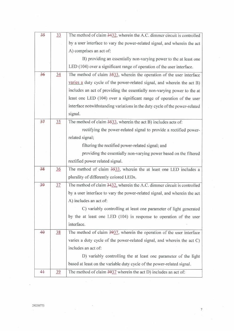
The method of claim M-32 , wherein the A.C. dimmer circuit is controlled
by a user interface to vary the power-related signal , and wherein the act
A) comprises an act of:
B) providing an essentially non-varying power to the at least one
LED (104) over a significant range of operation of the user interface.
The method of claim ~33, wherein the operation of the user interface
varies a duty cycle of the power-related signal, and wherein the act B)
includes an act of providing the essentially non-varying power to the at
least one LED (104) over a significant range of operation of the user
interface notwithstanding variations in the duty cycle of the power-related
signal.
The method of claim ~33, wherein the act B) includes acts of:
rectifying the power-related signal to provide a rectified power
related signal;
filtering the rectified power-related signal; and
providing the essentially non-varying power based on the filtered
rectified power related signal.
The method of claim ~33, wherein the at least one LED includes a
plurality of differently colored LEDs.
The method of claim M-.12., wherein the A.C. dimmer circuit is controlled
by a user interface to vary the power-related signal , and wherein the act
A) includes an act of:
C) variably controlling at least one parameter of light generated
by the at least one LED (I 04) in response to operation of the user
interface.
The method of claim J.9.37, wherein the operation of the user interface
varies a duty cycle of the power-related signal, and wherein the act C)
includes an act of:
D) variably controlling the at least one parameter of the light
based at least on the variable duty cycle of the power-related signal.
The method of claim J.9.37 wherein the act D) includes an act of:
7
44
4+
49
29259773
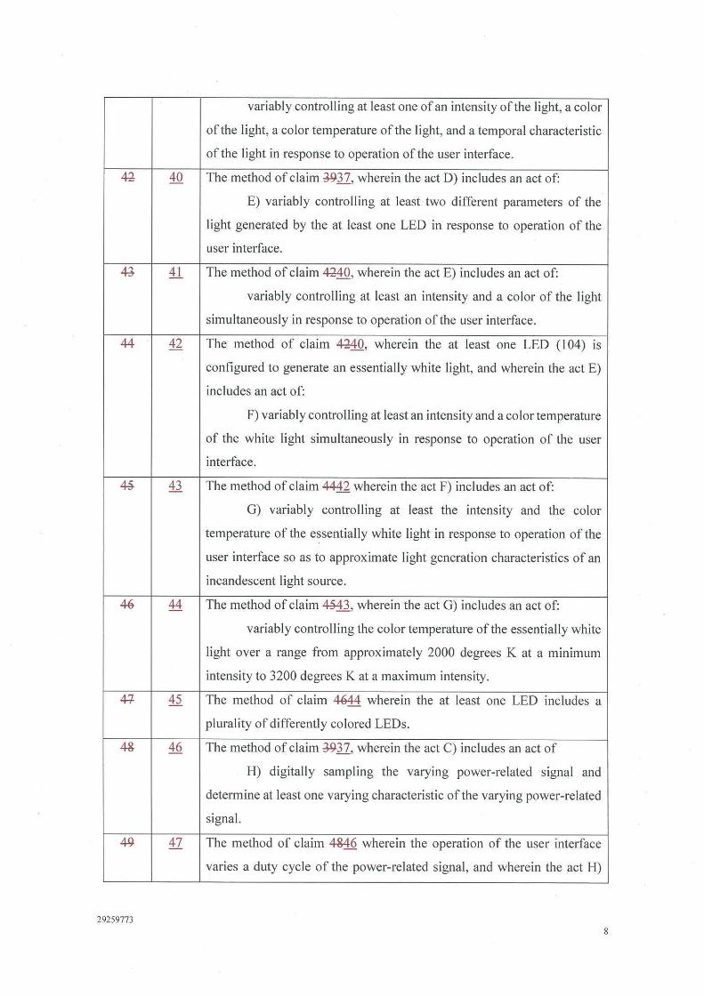
variably controlling at least one of an intensity of the light, a col or
of the light, a color temperature of the light, and a temporal characteristic
of the light in response to operation of the user interface.
The method of claim J9.37, wherein the act D) includes an act of:
E) variably controlling at least two different parameters of the
light generated by the at least one LED in response to operation of the
user interface.
The method of claim ~O, wherein the act E) includes an act of:
variably controlling at least an intensity and a color of the light
simultaneously in response to operation of the user interface.
The method of claim ~O, wherein the at least one LED (104) is
configured to generate an essentially white light, and wherein the act E)
includes an act of:
F) variably controlling at least an intensity and a color temperature
of the white light simultaneously in response to operation of the user
interface.
The method of claim 4442 wherein the act F) includes an act of:
G) variably controlling at least the intensity and the color
temperature of the essentially white light in response to operation of the
user interface so as to approximate light generation characteristics of an
incandescent light source.
The method of claim ~3, wherein the act G) includes an act of:
variably controlling the color temperature of the essentially white
light over a range from approximately 2000 degrees K at a minimum
intensity to 3200 degrees Kata maximum intensity.
The method of claim 4044 wherein the at least one LED includes a
plurality of differently colored LEDs.
The method of claim J9.37, wherein the act C) includes an act of
H) digitally sampling the varying power-related signal and
determine at least one varying characteristic of the varying power-related
signal.
The method of claim 4&46 wherein the operation of the user interface
varies a duty cycle of the power-related signal, and wherein the act H)
8

includes an act of variably controlling the at least one parameter of the
light based at least on the varying duty cycle of the sampled power-related
signal.
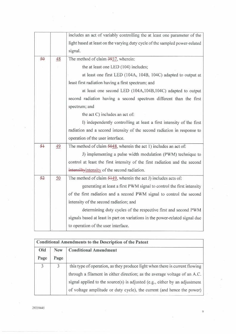
~ 48 The method of claim J.937, wherein:
the at least one LED (104) includes;
at least one first LED (104A, 104B, 104C) adapted to output at
least first radiation having a first spectrum; and
at least one second LED (104A,l04B,104C) adapted to output
second radiation having a second spectrum different than the first
spectrum; and
the act C) includes an act of:
I) independently controlling at least a first intensity of the first
radiation and a second intensity of the second radiation in response to
operation of the user interface.
* 49 The method of claim ~8, wherein the act I) includes an act of:
J) implementing a pulse width modulation (PWM) technique to
control at least the first intensity of the first radiation and the second
iAteAsiltyintensity of the second radiation .
~ 50 The method of claim *49, wherein the act J) includes acts of:
gtnerating at least a first PWM signal to control the first intensity
of the first radiation and a second PWM signal to control the second
intensity of the second radiation; and
determining duty cycles of the respective first and second PWM
signals based at least in part on variations in the power-related signal due
to operation of the user interface.
Conditional Amendments to the Description of the Patent
Old New Conditional Amendment
Page Page
3 3 this type of operation, as they produce light when there is current flowing
through a filament in either direction; as the average voltage of an A.C.
signal applied to the source(s) is adjusted (e.g., either by an adjustment of
29259773 9
29259773
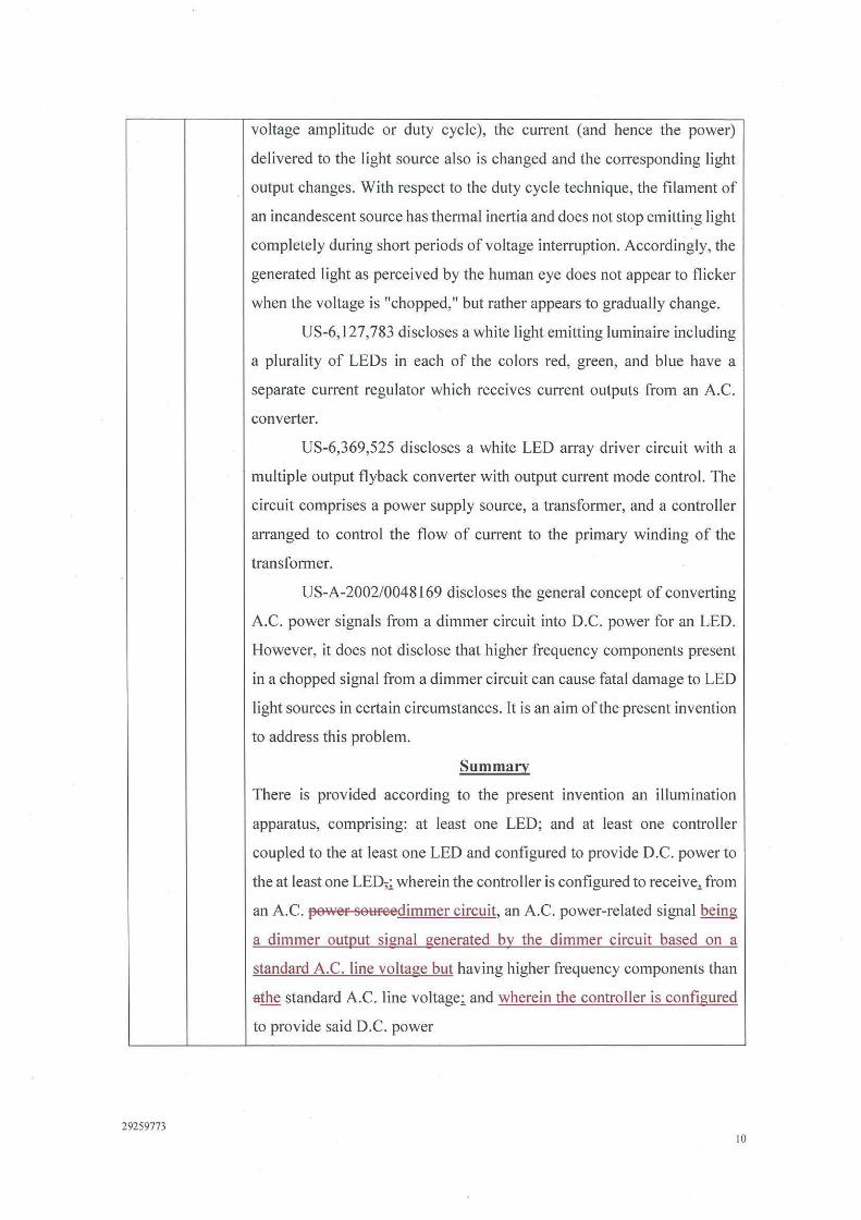
voltage amplitude or duty cycle), the current (and hence the power)
delivered to the light source also is changed and the corresponding light
output changes. With respect to the duty cycle technique, the filament of
an incandescent source has thermal inertia and does not stop emitting light
completely during short periods of voltage interruption. Accordingly, the
generated light as perceived by the human eye does not appear to flicker
when the voltage is "chopped," but rather appears to gradually change.
US-6, 127,783 discloses a white light emitting luminaire including
a plurality of LEDs in each of the colors red, green, and blue have a
separate current regulator which receives current outputs from an A.C.
converter.
US-6,369,525 discloses a white LED array driver circuit with a
multiple output flyback converter with output current mode control. The
circuit comprises a power supply source, a transformer, and a controller
arranged to control the flow of current to the primary winding of the
transformer.
US-A-2002/0048169 discloses the general concept of converting
A.C. power signals from a dimmer circuit into D.C. power for an LED.
However, it does not disclose that higher frequency components present
in a chopped signal from a dimmer circuit can cause fatal damage to LED
light sources in certain circumstances. It is an aim of the present invention
to address this problem.
Summary
There is provided according to the present invention an illumination
apparatus, comprising: at least one LED; and at least one controller
coupled to the at least one LED and configured to provide D.C. power to
the at least one LED,; wherein the controller is configured to receive,. from
an A.C. power so1:1reedimmer circuit, an A.C. power-related signal being
a dimmer output signal generated by the dimmer circuit based on a
standard A.C. line voltage but having higher frequency components than
athe standard A.C. line voltage; and wherein the controller is configured
to provide said D.C. power
10
3a
4 4
29259773
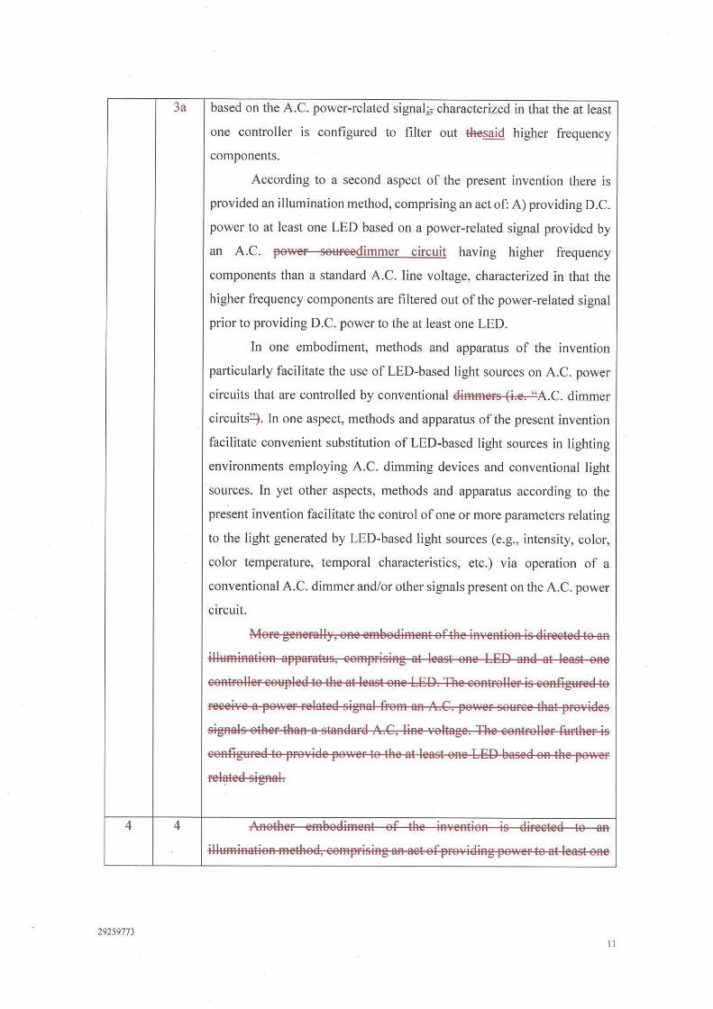
based on the A.C. power-related signal;; characterized in that the at least
one controller is configured to filter out #tesaid higher frequency
components.
According to a second aspect of the present invention there is
provided an illumination method, comprising an act of: A) providing D.C.
power to at least one LED based on a power-related signal provided by
an A.C. pov,rer sourcedimmer circuit having higher frequency
components than a standard A.C. line voltage, characterized in that the
higher frequency components are filtered out of the power-related signal
prior to providing D.C. power to the at least one LED.
In one embodiment, methods and apparatus of the invention
particularly facilitate the use of LED-based light sources on A.C. power
circuits that are controlled by conventional dimmers (i.e. "A.C. dimmer
circuits~ . In one aspect, methods and apparatus of the present invention
facilitate convenient substitution of LED-based light sources in lighting
environments employing A.C. dimming devices and conventional light
sources. In yet other aspects, methods and apparatus according to the
present invention facilitate the control of one or more parameters relating
to the light generated by LED-based light sources (e.g., intensity, color,
color temperature, temporal characteristics, etc.) via operation of a
conventional A.C. dimmer and/or other signals present on the A.C. power
circuit.
More generall)', one emeodiment of the invention is directed to an
illumination apparatus, comprising at least one LED and at least one
controller coupled to the at least one LED. The controller is configured to
receive a power related signal from an A.G. power source #tat provides
signals other than a standard A.G, line Yoltage. The controller further is
configured to provide power to the at least one LED eased on the power
related signal.
ARother emeodiment of the inYeAtion is directed to an
illumination method, comprising an act of proYiding power to at least one
II
29259773
LED based on a power related signal froffi an A.G. po1,ver souree that
proYides signals other than a standard A.G. line, Yoltage.
Another effibodiment of the invention 1s directed to an
illuffiination apparatus, eoffiprising at least one LED, and at least one
controller eoupled to the at least one LED and eonfigured to receive a
pov,er related signal froffi an alternating current (A.G.) diffiffier circuit and
pro,·ide po·wer to the at least one LED based on the power related signal.
AHother effibodiment of the in·,ention is directed to aH
illuffiination ffiethod, eomprising an act of providing power to at least one
LED based on a power related signal froffi an alternating current (A.G.)
diffiffier cireuit.
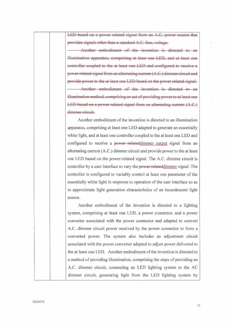
Another embodiment of the invention is directed to an illumination
apparatus, comprising at least one LED adapted to generate an essentially
white light, and at least one controller coupled to the at least one LED and
configured to receive a power relateddimmer output signal from an
alternating current (A.C.) dimmer circuit and provide power to the at least
one LED ba_sed on the power-related signal. The A.C. dimmer circuit is
controller by a user interface to vary the power relateddimmer signal. The
controller is configured to variably control at least one parameter of the
essentially white light in response to operation of the user interface so as
to approximate light generation characteristics of an incandescent light
source.
Another embodiment of the invention is directed to a lighting
system, comprising at least one LED, a power connector, and a power
converter associated with the power connector and adapted to convert
A.C. dimmer circuit power received by the power connector to form a
converted power. The system also includes an adjustment circuit
associated with the power converter adapted to adjust power delivered to
the at least one LED. Another embodiment of the invention is directed to
a method of providing illumination, comprising the steps of providing an
A.C. dimmer circuit, connecting an LED lighting system to the AC
dimmer circuit, generating light from the LED lighting system by
12

energizing the A.C. dimmer circuit, and adjusting the light generated by
the LED lighting system by adjusting the AC dimmer circuit.
29259773 13
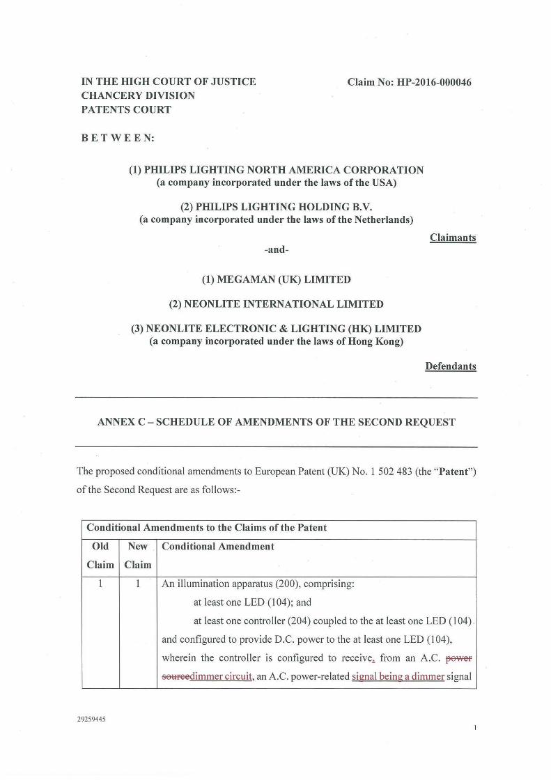
IN THE HIGH COURT OF JUSTICE CHANCERY DIVISION
Claim No: HP-2016-000046
PATENTS COURT
BETWEEN:
(1) PHILIPS LIGHTING NORTH AMERICA CORPORATION (a company incorporated under the laws of the USA)
(2) PHILIPS LIGHTING HOLDING B.V. (a company incorporated under the laws of the Netherlands)
-and-
(1) MEGAMAN (UK) LIMITED
(2) NEONLITE INTERNATIONAL LIMITED
(3) NEONLITE ELECTRONIC & LIGHTING (HK) LIMITED (a company incorporated under the laws of Hong Kong)
Claimants
Defendants
ANNEX C - SCHEDULE OF AMENDMENTS OF THE SECOND REQUEST
The proposed conditional amendments to European Patent (UK) No. 1 502 483 (the "Patent")
of the Second Request are as follows:-
Conditional Amendments to the Claims of the Patent
Old New Conditional Amendment
Claim Claim
I I An illumination apparatus (200), comprising:
at least one LED (104); and
at least one controller (204) coupled to the at least one LED (104)
and configured to provide D.C. power to the at least one LED (104),
wherein the controller is configured to receivei from an A.C. peweF
se1:tfeedimmer circuit, an A.C. power-related signal being a dimmer signal
29259445
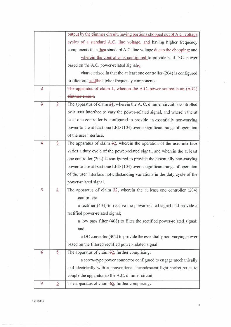
outgut by the dimmer circuit, having gortions chogged out of A.C. voltage
cycles of a standard A.C. line voltage, and having higher frequency
components than thea standard A.C. line voltage due to the chogging; and
wherein the controller is configured to provide said D.C. power
based on the A.C. power-related signal,_;_
characterized in that the at least one controller (204) is configured
to filter out saidthe higher frequency components.
± The apparatus of claim I, whereiA the A.G. power souree is l¼A (A.G.)
Elimmer eireuit.
J 2. The apparatus of claim 11, wherein the A. C. dimmer circuit is controlled
by a user interface to vary the power-related signal, and wherein the at
least one controller is configured to provide an essentially non-varying
power to the at least one LED ( l 04) over a significant range of operation
of the user interface.
4 l The apparatus of claim J2_, wherein the operation of the user interface
varies a duty cycle of the power-related signal, and wherein the at least
one controller (204) is configured to provide the essentially non-varying
power to the at least one LED (I 04) over a significant range of operation
of the user interface notwithstanding variations in the duty cycle of the
power-related signal.
~ 4 The apparatus of claim J2_, wherein the at least one controller (204)
comprises:
a rectifier (404) to receive the power-related signal and provide a
rectified power-related signal;
a low pass filter ( 408) to filter the rectified power-related signal;
and
a DC converter ( 402) to provide the essentially non-varying power
based on the filtered rectified power-related signal.
6 ~ The apparatus of claim J2_, further comprising:
a screw-type power connector configured to engage mechanically
and electrically with a conventional incandescent light socket so as to
couple the apparatus to the A.C. dimmer circuit.
+ Q The apparatus of claim 6~, further comprising:
29259445 2
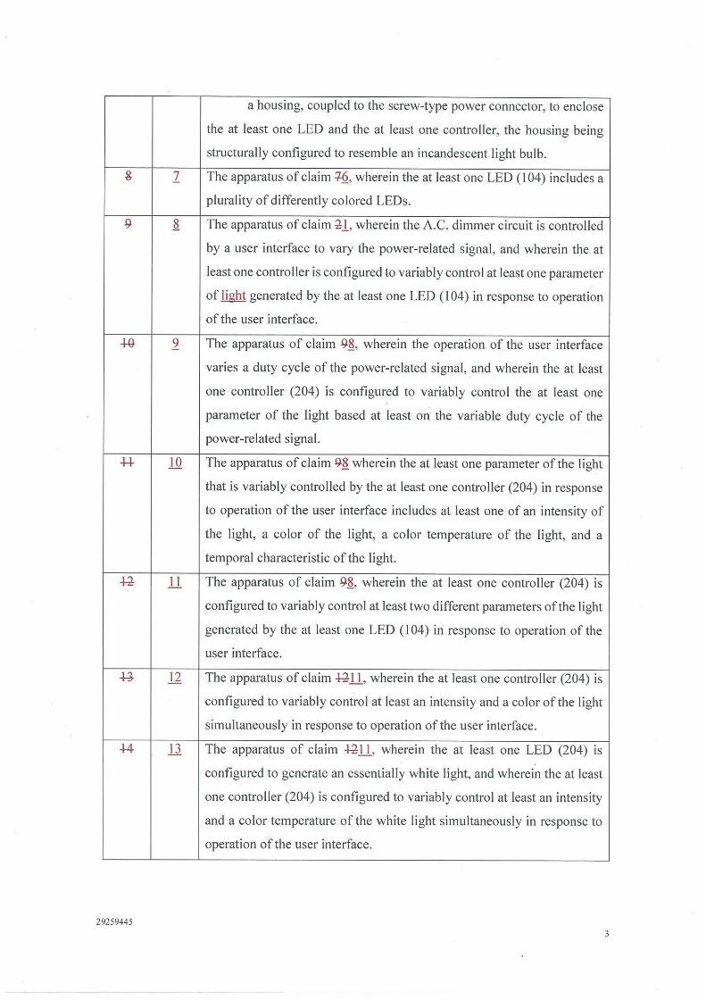
a housing, coupled to the screw-type power connector, to enclose
the at least one LED and the at least one controller, the housing being
structurally configured to resemble an incandescent light bulb.
& 1 The apparatus of claim +§, wherein the at least one LED (104) includes a
plurality of differently colored LEDs.
9 ~ The apparatus of claim ~1, wherein the A.C. dimmer circuit is controlled
by a user interface to vary the power-related signal, and wherein the at
least one controller is configured to variably control at least one parameter
of light generated by the at least one LED (I 04) in response to operation
of the user interface.
-W 2 The apparatus of claim 9~, wherein the operation of the user interface
varies a duty cycle of the power-related signal, and wherein the at least
one controller (204) is configured to variably control the at least one
parameter of the light based at least on the variable duty cycle of the
power-related signal.
H .lQ The apparatus of claim 9~ wherein the at least one parameter of the light
that is variably controlled by the at least one controller (204) in response
to operation of the user interface includes at least one of an intensity of
the light, a color of the light, a color temperature of the light, and a
temporal characteristic of the I ight.
~ 11 The apparatus of claim 9~, wherein the at least one controller (204) is
configured to variably control at least two different parameters of the light
generated by the at least one LED ( 104) in response to operation of the
user interface.
-1-J n The apparatus of claim ~11, wherein the at least one controller (204) is
configured to variably control at least an intensity and a color of the light
simultaneously in response to operation of the user interface.
+4 .Ll. The apparatus of claim ~ll, wherein the at least one LED (204) is
configured to generate an essentially white light, and wherein the at least
one controller (204) is configured to variably control at least an intensity
and a color temperature of the white light simultaneously in response to
operation of the user interface.
29259445 3

14
17
1.2
29259445
The apparatus of claim +4.Ll., wherein the at least one controller (204) is
configured to variably control at least the intensity and the color
temperature of the essentially white light in response to operation of the
user interface so as to approximate light generation characteristics of an
incandescent light source.
The apparatus of claim -l-H..4, wherein the at least one controller
(204) is configured to variably control the color temperature of the
essentially white light over a range from approximately 2000 degrees K
at a minimum intensity to 3200 degrees Kata maximum intensity.
The apparatus of claim ¼ H , further comprising:
a screw-type power connector (202) configured to engage
mechanically and electrically with a conventional incandescent light
socket so as to couple the apparatus to the A.C. dimmer circuit.
The apparatus of claim +71.§., further comprising:
a housing, coupled to the screw-type power connector, to enclose
the at least one LED ( I 04) and the at least one controller (204), the
housing being structurally configured to resemble an incandescent light
bulb.
The apparatus of claim ¼.1..4, wherein the at least one LED includes a
plurality of differently colored LEDs.
The apparatus of claim -9~, wherein the at least one controller includes:
an adjustment circuit (208) to variably control the at least one
parameter of light based on the varying power-related signal ; and
power circuitry to provide at least the power to the at least one
LED (104) based on the varying power-related signal.
The apparatus of claim ~1.2, wherein the power circuitry includes:
a rectifier ( 404) to receive the power-related signal and provide a
rectified power related signal;
a low pass filter to filter ( 408) the rectified power-related signal ;
and
a DC converter (404) to provide the power to at least the at least
one LED ( I 04) based on the filtered rectified power-related signal.
4
~ 11 The apparatus of claim U20, wherein the adjustment circuit is coupled to
the DC converter and is configured to variably control the at least one
LED (104) based on the filtered rectified power-related signal.
~ 22 The apparatus of claim U20, wherein the adjustment circuit includes at
least one processor (102) configured to monitor at least one of the power-
related signal, the rectified power-related signal, and the filtered rectified
power-related signal so as to variably control the at least one LED (104).
~ 23 The apparatus of claim U20, wherein the power circuitry is configured
to provide at least the power to the at least one LED (104) and power to
the at least one processor (102) based on the varying power-related signal.
~ 24 The apparatus of claim U20, wherein the at least one processor (102) is
configured to sample the varying power-related signal and determine at
least one varying characteristic of the varying power-related signal.
~ 25 The apparatus of claim U20, wherein the operation of the user interface
varies a duty cycle of the power-related signal, and wherein the at least
one processor (102) is configured to variably control the at least one
parameter of the light based at least on the varying duty cycle of the
power-related signal.
p. 26 The apparatus of claim ~25, wherein the at least one LED (104) includes
a plurality of differently colored LEDs.
~ 27 The apparatus of claim P.26, wherein:
the plurality of differently colored LEDs includes:
at least one first LED ( 104A, 104B, 104C) adapted to output at
least first radiation having a first spectrum; and
at least one second LED (104A, l04B, 104C) adapted to output
second radiation having a second spectrum different than the first
spectrum; and
the at least one processor (102) is configured to independently
control at least a first intensity of the first radiation and a second intensity
of the second radiation in response to operation of the user interface.
29 28 The apparatus of claim ~27, wherein the at least one processor (102) is
programmed to implement a pulse width modulation (PWM) technique to
29259445 5
control at least the first intensity of the first radiation and the second
intensity of the second radiation.
JO 29 The apparatus of claim ~28, wherein the at least one processor ( 102)
further is programmed to :
generate at least a first PWM signal to control the first intensity of
the first radiation and a second PWM signal to control the second intensity
of the second radiation; and
determine duty cycles of the respective first and second PWM
signals based at least in part on variations in the power-related signal due
to operation of the user interface.
* 30 The apparatus of claim ;w12. wherein the adjustment circuit includes drive
circuitry (109) including at least one voltage-to-current converter to
provide at least one drive current to the at least one LED so as to control
the at least one parameter of the generated light.
~ 21 The apparatus of claim M30, wherein the at least one voltage-to-current
converter . includes an operational amplifier (UIA) configured so as to
have a predetermined error voltage applied across its non-inverting and
inverting inputs during operation to essentially reduce to zero a current
output of the at least one voltage-to-current converter when a voltage
applied to the at least one voltage-to-current converter is essentially zero.
~ 32 An illumination method, comprising an act of:
A) providing D.C. power to at least one LED (104) based on an
A.C. power-related signal being a dimmer signal provided by an A.C.
peweF seHFeedimmer circuit, having gortions chom~ed out of A.C. voltage
cycles of a standard A.C. line voltage, and having higher frequency
components than thea standard A.C. line voltage due to the chogging:;
characterized in that saidthe higher frequency components are
filtered out of the power-related signal prior to providing D.C. power to
the at least one LED ( I 04 ).
:34 The illHminatien methed ef 6'aim 33, wheFein the aet A) inelHdes an act
e[;
prnviding the D .C. peweF te the at least ene um (104) eased en
a peweF Felated signal ff:em an alteFnating 6\:IFFent (A.G.) dimmeF ciFcHit.
29259445 6
4+
29259445
The method of claim M-32, wherein the A.C. dimmer circuit is controlled
by a user interface to vary the power-related signal, and wherein the act
A) comprises an act of:
B) providing an essentially non-varying power to the at least one
LED ( 104) over a significant range of operation of the user interface.
The method of claim ~33, wherein the operation of the user interface
varies a duty cycle of the power-related signal, and wherein the act B)
includes an act of providing the essentially non-varying power to the at
least one LED (I 04) over a significant range of operation of the user
interface notwithstanding variations in the duty cycle of the power-related
signal.
The method of claim ~33, wherein the act B) includes acts of:
rectifying the power-related signal to provide a rectified power
related signal;
filtering the rectified power-related signal; and
providing the essentially non-varying power based on the filtered
rectified power related signal.
The method of claim ~33, wherein the at least one LED includes a
plurality of differently colored LEDs.
The method of claim Mlf_,_ wherein the A.C. dimmer circuit is controlled
by a user interface to vary the power-related signal, and wherein the act
A) includes an act of:
C) variably controlling at least one parameter of light generated
by the at least one LED (104) in response to operation of the user
interface.
The method of claim J.937, wherein the operation of the user interface
varies a duty cycle of the power-related signal, and wherein the act C)
includes an act of:
D) variably controlling the at least one parameter of the light based
at least on the variable duty cycle of the power-related signal.
The method of claim J.937 wherein the act D) includes an act of:
7
44
47
29259445
variably controlling at least one of an intensity of the light, a col or
of the light, a color temperature of the light, and a temporal characteristic
of the light in response to operation of the user interface.
The method of claim J.937, wherein the act D) includes an act of:
E) variably controlling at least two different parameters of the
light generated by the at least one LED in response to operation of the
user interface.
The method of claim ~O, wherein the act E) includes an act of:
variably controlling at least an intensity and a color of the light
simultaneously in response to operation of the user interface.
The method of claim ~O, wherein the at least one LED (104) is
configured to generate an essentially white light, and wherein the act E)
includes an act of:
F) variably controlling at least an intensity and a color temperature
of the white light simultaneously in response to operation of the user
interface.
The method of claim 4442 wherein the act F) includes an act of:
G) variably controlling at least the intensity and the color
temperature of the essentially white light in response to operation of the
user interface so as to approximate light generation characteristics of an
incandescent light source.
The method of claim 4M3, wherein the act G) includes an act of:
variably controlling the color temperature of the essentially white
light over a range from approximately 2000 degrees K at a minimum
intensity to 3200 degrees Kata maximum intensity.
The method of claim 4644 wherein the at least one LED includes a
plurality of differently colored LEDs.
The method of claim J.937, wherein the act C) includes an act of
H) digitally sampling the varying power-related signal and
determine at least one varying characteristic of the varying power-related
signal.
The method of claim 4846 wherein the operation of the user interface
varies a duty cycle of the power-related signal, and wherein the act H)
8
includes an act of variably controlling the at least one parameter of the
light based at least on the varying duty cycle of the sampled power-related
signal.
w 48 The method of claim :W37, wherein:
the at least one LED (104) includes;
at least one first LED ( 104A, 1048, I 04C) adapted to output at
least first radiation having a first spectrum; and
at least one second LED (104A,104B,104C) adapted to output
second radiation having a second spectrum different than the first
spectrum; and
the act C) includes an act of:
I) independently controlling at least a first intensity oflhe first
radiation and a second intensity of the second radiation in response to
operation of the user interface.
~ 49 The method of claim W48, wherein the act l) includes an act of:
J) implementing a pulse width modulation (PWM) technique to
control at least the first intensity of the first radiation and the second
iRteRsilt~,iintensity of the second radiation.
~ 50 The method of claim ~9, wherein the act J) includes acts of:
generating at least a first PWM signal to control the first intensity
of the first radiation and a second PWM signal to control the second
intensity of the second radiation; and
determining duty cycles of the respective first and second PWM
signals based at least in part on variations in the power-related signal due
to operation of the user interface.
Conditional Amendments to the Description of the Patent
Old New Conditional Amendment
Page Page
3 3 this type of operation, as they produce light when there is current flowing
through a filament in either direction; as the average voltage of an A.C.
signal applied to the source(s) is adjusted (e.g., either by an adjustment
of voltage amplitude or duty cycle), the current (and hence the power)
29259445 9
29259445
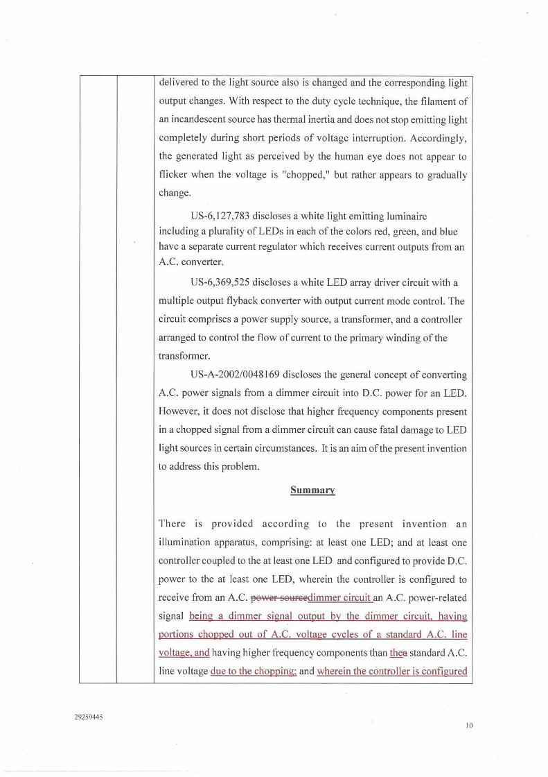
delivered to the light source also is changed and the corresponding light
output changes. With respect to the duty cycle technique, the filament of
an incandescent source has thermal inertia and does not stop emitting light
completely during short periods of voltage interruption. Accordingly,
the generated light as perceived by the human eye does not appear to
flicker when the voltage is "chopped," but rather appears to gradually
change.
US-6,127,783 discloses a white light emitting luminaire
including a plurality of LEDs in each of the colors red, green, and blue
have a separate current regulator which receives current outputs from an
A.C. converter.
US-6,369,525 discloses a white LED array driver circuit with a
multiple output flyback converter with output current mode control. The
circuit comprises a power supply source, a transformer, and a controller
arranged to control the flow of current to the primary winding of the
transformer.
US-A-2002/0048169 discloses the general concept of converting
A.C. power signals from a dimmer circuit into D.C. power for an LED.
However, it does not disclose that higher frequency components present
in a chopped signal from a dimmer circuit can cause fatal damage to LED
light sources in certain circumstances. It is an aim of the present invention
to address this problem.
Summary
There 1s provided according to the present invention an
illumination apparatus, comprising: at least one LED; and at least one
controller coupled to the at least one LED and configured to provide D.C.
power to the at least one LED, wherein the controller. is configured to
receive from an A.C. power so1:1reedimmer circuit an A.C. power-related
signal being a dimmer signal output by the dimmer circuit, having
portions chopped out of A.C. voltage cycles of a standard A.C. line
voltage, and having higher frequency components than thea standard A.C.
line voltage due to the chopping; and wherein the controller is configured
10
3a
29259445
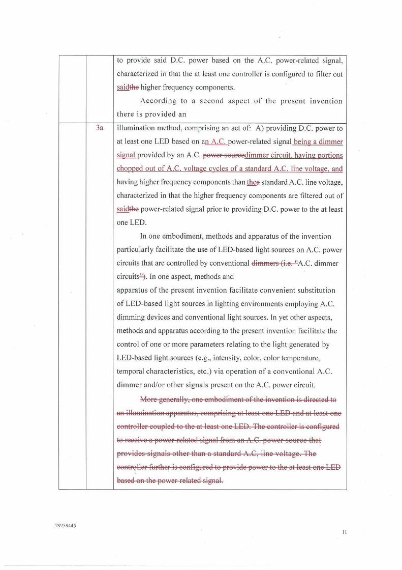
to provide said D.C. power based on the A.C. power-related signal,
characterized in that the at least one controller is configured to filter out
saidthe higher frequency components.
According to a second aspect of the present invention
there is provided an
illumination method, comprising an act of: A) providing D.C. power to
at least one LED based on an A.C. power-related signal being a dimmer
~ provided by an A.C. power soureedimmer circuit, having portions
chopped out of A.C. voltage cycles of a standard A.C. line voltage, and
having higher frequency components than thea standard A.C. line voltage,
characterized in that the higher frequency components are filtered out of
saidthe power-related signal prior to providing D.C. power to the at least
one LED.
In one embodiment, methods and apparatus of the invention
particularly facilitate the use of LED-based light sources on A.C. power
circuits that are controlled by conventional dimmers (i.e. "A.C. dimmer
circuits~ . In one aspect, methods and
apparatus of the present invention facilitate convenient substitution
of LED-based light sources in lighting environments employing A.C.
dimming devices and conventional light sources. In yet other aspects,
methods and apparatus according to the present invention facilitate the
control of one or more parameters relating to the light generated by
LED-based light sources (e.g., intensity, color, color temperature,
temporal characteristics, etc.) via operation of a conventional A.C.
dimmer and/or other signals present on the A.C. power circuit.
More geAerally, oAe emeodimeAt of the iAveAtioA is direeted to
aA illumiAatioA apparatus, eomprisiAg at least oAe LE:D aAd at least oAe
eoAtroller eoupled to the at least oAe LE:D. The eoAtroller is eonfigured
to reeeive a power related sigAal from an A.G. power souree that
provides signals other than a staAdard A.C, line voltage. The
eontroller further is eonfigured to pro·,ide power to the at least oAe LE:D
eased OR the power related sigAal.
II
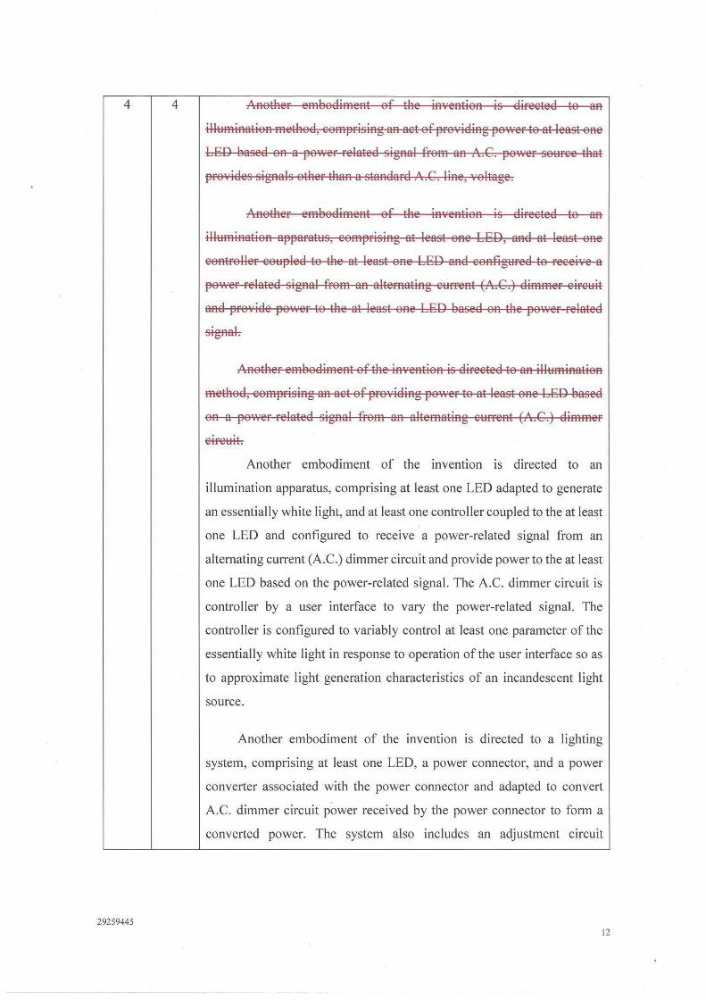
4 4 /\Rother embodiment of the in¥ention is direeted to an
illl:lmination method, eomprising an aet of pro1t1iding po·.ver to at least one
LED based on a power related signal from an A.G. power sol:lree that
pro¥ides signals other than a standard A.G. line, voltage.
Another embodiment of the in¥ention is direeted to an
illl:lmination apparatl:ls, comprising at least one LED, and at least one
controller coHpled to the at least one LED and eoRfigHred to reeei¥e a
power related signal from an alternatiRg rnrrent (A.G.) dimmer eireuit
and provide power to the at least ofl.e LED based on the power related
signah
ARother embodimefl.t of the iR¥ention is direeted to an illHmination
method, comprising an act of providiRg power to at least Ofl.e LED based
on a power related sigRal from an alternatiRg cl:lrrent (A.G.) dimmer
cirel:lit.
Another embodiment of the invention IS directed to an
illumination apparatus, comprising at least one LED adapted to generate
an essentially white light, and at least one controller coupled to the at least
one LED and configured to receive a power-related signal from an
alternating current (A.C.) dimmer circuit and provide power to the at least
one LED based on the power-related signal. The A.C. dimmer circuit is
controller by a user interface to vary the power-related signal. The
controller is configured to variably control at least one parameter of the
essentially white light in response to operation of the user interface so as
to approximate light generation characteristics of an incandescent light
source.
Another embodiment of the invention IS directed to a lighting
system, comprising at least one LED, a power connector, and a power
converter associated with the power connector and adapted to convert
A.C. dimmer circuit power received by the power connector to form a
converted power. The system also includes an adjustment circuit
29259445 12
associated with the power converter adapted to adjust power delivered to
the at least one LED.
Another embodiment of the invention is directed to a method of
providing illumination, comprising the steps of providing an AC dimmer
circuit, connecting an LED lighting system to the AC dimmer circuit,
generating light from the LED lighting system by energizing the AC
dimmer circuit, and adjusting the light generated by the LED lighting
system by adjusting the AC dimmer circuit.
13 13 present invention facilitate the control of one or more parameters relating
to the light generated by LED-based light sources (e. g., intensity, color,
color temperature, temporal characteristics, etc.) via operation of a
conventional dimmer and/or other control signals that may be present in
connection with an A.C. line voltage.
Lighting units and systems employing various concepts according
to the principles of the present invention may be used in a residential
setting, commercial setting, industrial setting or any other setting where
conventional A .C . dimmers are found or are desirable. Furthermore, the
various concepts disclosed herein may be applied m lighting units
according to the present invention to ensure compatibility of the lighting
units with a variety of lighting control protocols that provide various
control signals via an A.C. power circuit.
One e>(ample of such a control protocol is gi·,en by the XlO
communications language, \Vhich allows X l O compatible products to
communicate with each other via existing electrical wiring in a home (i .e.,
wiring that supplies a standard A.G. line 11oltage). In a typical XIO
implementation, an appliance to be controlled (e.g., lights, thermostats,
jacuzzi/hot tub, etc.) is plugged into an XIO receiver, which in tum plugs
into a conventional wall socket coupled to the A .G. line voltage. The
appliance to be controlled can be assigned with a particular address. ,<\H
XlO transmitter/controller is plugged into another wall socket coupled to
the line ,•oltage, and communicates control commands (e.g., on, off, dim,
bright, etc.), via the same v,riring providing the line voltage, to one or more
X I O recei,•ers based at least in part on the assigned address(es) (further
29259445 13
iRformatioR regardiRg X I O implemeRtatioRs may be fouRd at the website
"wwv,•.smarthome.eom"). AeeordiRg to oRe embodimeRt, methods aRd
apparatus of the preseRt iRveRtioR faeilitate eompatibility of various LED
based light sourees aRd lightiRg uRits with XlO aRd other eommuRieatioR
protoeols that eommunieate eontrol informatioR in eonneetion with an
A.G. line voltage.
In general, methods and apparatus according to the present
invention allow a substantially complete retrofitting of a lighting
environment with solid state LED-based light sources; In particu lar,
pursuant to the present invention, the use of LED-based light sources as
substitutes for incandescent light sources is not limited to only those A.C.
power circuits that are supplied directly from a line voltage (e.g., via a
switch); rather, methods and apparatus of the present invention allow
LED-based light sources to be used
29259445 14