Embed Size (px)
Citation preview

AMDAR Onboard Software Functional
Requirements Specification
(Version 1.1, 2 June 2014)
Instruments and Observing Methods
Report No. 115

This publication is available in pdf format, at the following link:
http://www.wmo.int/pages/prog/www/IMOP/publications-IOM-series.html
© World Meteorological Organization, 2014 The right of publication in print, electronic and any other form and in any language is reserved by WMO. Short extracts from WMO publications may be reproduced without authorization, provided that the complete source is clearly indicated. Editorial correspondence and requests to publish, reproduce or translate this publication (articles) in part or in whole should be addressed to: Chairperson, Publications Board World Meteorological Organization (WMO) 7 bis, avenue de la Paix Tel.: +41 (0) 22 730 8403 P.O. Box 2300 Fax: +41 (0) 22 730 8040 CH-1211 Geneva 2, Switzerland E-mail: [email protected]
NOTE
The designations employed in WMO publications and the presentation of material in this publication do not imply the expression of any opinion whatsoever on the part of WMO concerning the legal status of any country, territory, city or area, or of its authorities, or concerning the delimitation of its frontiers or boundaries. The mention of specific companies or products does not imply that they are endorsed or recommended by WMO in preference to others of a similar nature which are not mentioned or advertised. The findings, interpretations and conclusions expressed in WMO publications with named authors are those of the authors alone and do not necessarily reflect those of WMO or its Members.
This publication has been issued without formal editing.

FOREWORD
The WMO Aircraft Meteorological Data Relay (AMDAR) observing system is a subcomponent of
the WMO Global Observing System, which is defined and maintained under the WMO World Weather Watch Program. AMDAR now provides more than 400,000 meteorological observations per day on the WMO Global Telecommunications System and comprises over 3000 commercial jet aircraft that collect and report high quality wind and temperature data according to WMO specification, utilizing predominantly onboard sensors and computing and avionics systems. This excellent collaboration between National Meteorological and Hydrological Services and the airline industry provides a highly valued supplement to the more conventional sources of upper air meteorological data derived from the satellite and radiosonde monitoring programs.
At the current time, there is still considerable potential for growth and expansion of the AMDAR observing system. This expansion would improve tropospheric upper air data coverage over many currently data-sparse areas of the globe and, as has been demonstrated from the knowledge and measurement of the significant positive impacts the data product has on numerical weather prediction computer models and forecast applications, would have considerable benefits for meteorological applications and related data user communities and the aviation industry.
This document provides a functional specification for AMDAR onboard software, which can be utilized by avionics software developers to build avionics software applications for AMDAR that will efficiently meet WMO standards and requirements for reporting of meteorological data from the aircraft platform utilizing aviation communications protocols and infrastructure.
I wish to thank the consultant, Mr Frank Tamis, who worked under the direction of the former WMO AMDAR Panel and the CBS Expert Team on Aircraft-Based Observing Systems in the compilation of the initial drafts of the specification and also the Members of the CIMO Task Team on Aircraft-based Observations who were responsible for the final revisions and assessment for publication. Thanks are also expressed to the WMO Secretariat for overall coordination of the work and expert input to the specification.
(Prof. B. Calpini)
President
Commission for Instruments and Methods of Observation
TableofContents
1 ................................................................................................................. 7 INTRODUCTION
1.1 ..................................................................................................................7 BACKGROUND1.2 .....................................................................................................................7 OBJECTIVES
1.3 .........................................................................................7 INTENDED AUDIENCE AND SCOPE1.4 .................................................................................................................8 CONVENTIONS1.5 ...................................................................................................8 APPLICABLE DOCUMENTS
1.6 .........................................................................................9 ABBREVIATIONS AND ACRONYMS
2 ............................................................................................ 10 AMDAR SYSTEM OVERVIEW
2.1 ...........................................................................................................10 AMDAR SYSTEM2.2 ..................................................11 AMDAR ONBOARD COMPONENT OF THE AMDAR SYSTEM2.3 ....................................................................................................13 OTHER SPECIFICATIONS2.3.1 ......................................................................................14 ARINC 620 versus this document
2.4 .........................................................................................................16 FURTHER READING
3 ............................................................. 17 AMDAR ONBOARD SOFTWARE REQUIREMENTS
3.1 .........................................................................................................18 DATA ACQUISITION3.2 ............................................................................................................20 DATA HANDLING3.2.1 .........................................................................................................20 Data acquisition rate3.2.2 ..................................................................................................................20 Data Validation3.2.3 ................................................................................................................21 Data Smoothing3.2.4 ..........................................................................................................21 Derived Parameters3.2.4.1 ...........................................................................................................21 Phase of Flight
3.2.4.1.1 ................................................................................................................21 Ground3.2.4.1.2 .................................................................................................................21 Ascent3.2.4.1.3 .............................................................................................................21 En‐Route3.2.4.1.4 ...............................................................................................................22 Descent
3.2.4.2 .....................................................................................................22 Turbulence Metric3.2.4.3 ..........................................................22 Water Vapor / Relative Humidity / Dew Point3.2.4.4 ...........................................................................................................22 Roll Angle Flag3.2.4.5 ................................................................................23 Aircraft Configuration Indicator
3.3 .................................................................................................24 AMDAR OBSERVATIONS
3.3.1 .................................................................................................25 Ascent Initial Observation3.3.2 .........................................................................................................25 Ascent Observations3.3.3 .......................................................................................................26 Descent Observations3.3.4 ........................................................................................................26 Routine Observations3.3.4.1 ....................................................................................26 Ascent Routine Observations3.3.4.2 .................................................................................26 En‐route Routine Observations3.3.4.3 ..................................................................................26 Descent Routine Observations3.3.4.4 ....................................................................................26 Maximum Wind Observation
3.3.5 ................................................................................................27 EDR Routine Observations3.3.6 .................................................................................................27 Touch‐down Observation
3.4 ..........................................................................27 FLIGHT PHASES AND REPORTING SCHEMES
IOM Report No. 115, AOSFRS version 1.1 Page 4 of 97

3.4.1 ....................................................................................................28 Pressure Based Scheme3.4.1.1 ........................................................................................................................28 Ascent
3.4.1.1.1 ..................................................................28 Ambient Static Pressure at Take‐Off3.4.1.1.2 ..................................................................................29 Initial Ascent Observation3.4.1.1.3 .......................................................................................................29 Ascent Part 13.4.1.1.4 .......................................................................................................29 Ascent Part 23.4.1.1.5 .............................................................................29 Ascent Routine Observations
3.4.1.2 ......................................................................................................................29 Descent3.4.1.2.1 ...................................................................................30 Touch‐down Observation3.4.1.2.2 ...........................................................................30 Descent Routine Observations
3.4.2 ..........................................................................................................30 Time Based Scheme3.4.2.1 ........................................................................................................................30 Ascent
3.4.2.1.1 ..................................................................................30 Initial Ascent Observation3.4.2.1.2 ..................................................................................................................30 Part 13.4.2.1.3 ..................................................................................................................30 Part 2
3.4.2.2 ......................................................................................................................30 Descent3.4.2.2.1 ...................................................................................30 Touch‐down Observation
3.5 ..................................................................................................31 MESSAGE COMPILATION
3.5.1 .............................................................................................................................31 Content3.5.2 ............................................................................................................................... 31 Format3.5.2.1 .......................................................................................................31 ACARS messages
3.5.3 ..............................................................................................31 Transmission Requirements
3.6 ...............................................................................33 SOFTWARE CONFIGURATION CONTROL3.6.1 ........................................................................................33 Observation Frequency Control3.6.2 ..............................................................................................................35 Reporting Control3.6.2.1 ........................................................................................................35 Reporting on/off3.6.2.2 ......................................................................................36 Geographical Control boxes3.6.2.3 ..........................................................................................36 Airport specific reporting3.6.2.4 .............................................................................................................37 Time Limiting3.6.2.5 .....................................................................................37 EDR Event message settings
3.6.3 .....................................................................................................37 Configuration Message3.6.4 .........................................................................................38 AMDAR Optimization Message
APPENDIX A ............................. 39 AOSFRS RECOMMENDED MESSAGE FORMAT FOR ACARS
A.1 ..............................................................................................................39 INTRODUCTIONA.2 ...................................................................39 AOSFRS DOWNLINK DATA MESSAGE FORMAT
A.2.1 .................................................................................................................39 Header BlockA.2.2 .....................................................................................................................40 Data BlockA.2.2.1 .....................................................................................40 Basic Observation SequenceA.2.2.2 .................................................................................................40 Optional Parameters
A.3 .....................................................................................................44 EDR EVENT MESSAGE
A.4 ..........................................47 AOSFRS CONFIGURATION FUNCTIONALITY AND UPLINK CONTROLA.4.1 .......................................................................................................47 Basic ConfigurationA.4.2 ................................................................................................50 Extended ConfigurationA.4.2.1 ......................................................................................50 Geographical Control BoxesA.4.2.2 ............................................................................51 Airport Configuration ParametersA.4.2.3 ....................................................51 Routine Observations and Wind Reporting StatusA.4.2.4 .............................................................................52 Ascent Configuration ParametersA.4.2.5 ...........................................................................53 Descent Configuration Parameters
A.4.3 ..........................................................................................53 Example Command Uplinks
IOM Report No. 115, AOSFRS version 1.1 Page 5 of 97

A.5 ......................................................................56 AOSFRS CONFIGURATION STATUS MESSAGE
APPENDIX B ................................................ 57 ADDITIONAL AOSFRS DOWNLINK MESSAGES
B.1 .................................................57 AOSFRS CONFIGURATION STATUS MESSAGE (ALTERNATIVE)B.2 ....................................................................................59 AOSFRS OPTIMIZATION MESSAGE
APPENDIX C ................................................................ 60 OPTIONAL DERIVED PARAMETERS
C.1 .................................................................................................................60 TURBULENCEC.1.1 ..........................................................................60 Derived Equivalent Vertical Gust (DEVG)C.1.2 ..............................................................................................62 Eddy Dissipation Rate (EDR)C.1.2.1 .........................................................................................................62 EDR CalculationC.1.2.2 .........................................................63 EDR Reporting Algorithm and AOS Integration
C.2 .............................................................................69 ATMOSPHERIC WATER VAPOR CONTENTC.2.1 ............................................................................................................70 The WVSSII SensorC.2.1.1 ...............................................................................................................70 IntroductionC.2.1.2 ...................................................................70 Current Input Variables and CalculationC.2.1.3 ..........................................................71 Presenting the 5‐character Mixing Ratio FieldC.2.1.4 .............................................................................71 The Quality Control Character (Q)
APPENDIX D ..................................................................................... 73 DATA COMPRESSION
D.1 ..................................................................................................73 BASE‐40 COMPRESSION
D.2 .....................................................................................................74 DELTA‐COMPRESSION
D.3 .................................................75 AOSFRS COMPRESSED DOWNLINK DATA MESSAGE FORMAT
D.4 ......................................................................................77 ENCODING COMPRESSED VALUESD.5 ......................................................................................79 DECODING COMPRESSED VALUES
APPENDIX E .............................................................. 81 PLATFORM SPECIFIC INFORMATION
E.1 ..............................................................................................81 HONEYWELL DATA SYSTEMS
E.2 ..................................................................................82 TELEDYNE CONTROLS DATA SYSTEMS
APPENDIX F ................................................................... 83 AVIONICS INFORMATION FORM
APPENDIX G ...... 84 AOSFRS APPLICATIONS DEVELOPMENT REQUIREMENTS SPECIFICATION
APPENDIX H ........................................................................... 96 AOSFRS VERSION CONTROL
IOM Report No. 115, AOSFRS version 1.1 Page 6 of 97
1 Introduction
1.1 BackgroundThe Global Aircraft Meteorological Data Relay (AMDAR) Program is a program initiated by the World
Meteorological Organization (WMO) in cooperation with aviation partners, and is used to collect
meteorological data worldwide from commercial aircraft. The WMO AMDAR Observing System is a
sub‐component of the WMO Global Observing System, which is defined and maintained under the
WMO World Weather Watch Program1.
Existing aircraft onboard sensors, computers and communications systems are utilized to collect,
process, format and transmit the meteorological data to ground stations via satellite or radio links.
Once on the ground, the data is relayed to National Meteorological and Hydrological Services
(NMHS), where it is processed, quality controlled and transmitted on the WMO Global
Telecommunications System (GTS).
The data collected is used for a range of meteorological applications, including, public weather
forecasting, climate monitoring and prediction, early warning systems for weather hazards and,
importantly, weather monitoring and prediction in support of the aviation industry.
1.2 ObjectivesThis document provides a comprehensive functional specification for AMDAR onboard software. It is
intended that the specification provides sufficient information to enable detailed technical
specifications to be provided for AMDAR Onboard Software implementation on suitable avionics
platforms.
Version 1.1 of the AMDAR Onboard Software Functional Requirements Specification (AOSFRS) is an
update to AOSFRS Version 1.0 that has been produced with the main objective to ensure that this
specification can and will be aligned with the Airlines Electronic Engineering Committee (AEEC)
ARINC 620 Supplement 8 (ARINC 620‐S8). It is expected that ARINC 620‐S8 will contain the format
specification of the Meteorological Report Version 6, which will reference AOSFRS Version 1.1 for
the full specification of AMDAR onboard software requirements.
1.3 IntendedAudienceandScopeThe specification is primarily intended for use by both meteorological agencies and avionics software
developers to allow them to jointly develop AMDAR software with minimal additional information. It
defines the Functional Specifications of the AMDAR Onboard Software only. Functional
Specifications of other parts of the AMDAR data flow, such as ground‐based processing, are outside
its scope.
The specification will be applicable for all kinds of on‐board data processing and communications
system solutions, including ACARS and/or successors.
1 The WMO World Weather Watch Programme: http://www.wmo.int/pages/prog/www/index_en.html
IOM Report No. 115, AOSFRS version 1.1 Page 7 of 97

By definition, an aircraft‐based meteorological observing system that conforms to this specification,
and most particularly to those requirements that are designated as required (see conventions,
paragraph 1.4), can be considered an AMDAR observing system.
1.4 ConventionsThe key words "must", "must not", "required", "shall", "shall not", "should", "should not",
"recommended", "may", and "optional" in this document are to be interpreted as follows:
1. The terms “SHALL”, "REQUIRED" or "MUST" mean that the definition is an absolute requirement
of the specification.
2. The phrases “SHALL NOT” or "MUST NOT" mean that the definition is an absolute prohibition of
the specification.
3. The terms “SHOULD” or "RECOMMENDED" mean that there may exist valid reasons in particular
circumstances to ignore a particular item, but the full implications must be understood and carefully
weighed before choosing a different course.
4. The phrases “SHOULD NOT “ or "NOT RECOMMENDED" mean that there may exist valid reasons in
particular circumstances when the particular behavior is acceptable or even useful, but the full
implications should be understood and the case carefully weighed before implementing any
behavior described with this label.
5. The terms “MAY” or "OPTIONAL" mean that an item is truly optional. One vendor may choose to
include the item because a particular marketplace requires it or because the vendor feels that it
enhances the product while another vendor may omit the same item. An implementation which
does not include a particular option MUST be prepared to interoperate with another
implementation which does include the option, though perhaps with reduced functionality. In the
same vein an implementation which does include a particular option MUST be prepared to
interoperate with another implementation which does not include the option (except, of course, for
the feature the option provides.)
1.5 ApplicableDocumentsWhere appropriate, references are provided to WMO, International Civil Aviation Organization
(ICAO), Aeronautical Radio Incorporated (ARINC) or other documents that are subject to issue and
review by the respective organizations. No recommendations or other information in this
specification overrides or supersedes the requirements contained in referenced documents, unless
specified otherwise.
IOM Report No. 115, AOSFRS version 1.1 Page 8 of 97

1.6 AbbreviationsandAcronymsACARS Aircraft Communication Addressing and Reporting System ACMS Aircraft Condition Monitoring System AEEC Airlines Electronic Engineering Committee AMDAR Aircraft Meteorological Data Relay AOS AMDAR Onboard Software AOSFRS AMDAR Onboard Software Functional Requirement Specification ARINC Aeronautical Radio, Incorporated ASDAR Aircraft to Satellite Data Relay DAS Data Acquisition System DEVG Derived Equivalent Vertical Gust EDR Eddy Dissipation Rate FMC Flight Management Computer GNSS Global Navigation Satellite System IATA International Air Transport Association ICAO International Civil Aviation Organization IRS Inertial Reference System NCAR National Center for Atmospheric Research (USA) NMHS National Meteorological and Hydrological Service Q/C Quality Control SAT Static Air Temperature TAT Total Air Temperature UTC Universal Time Coordinate WMO World Meteorological Organization VHF Very High Frequency
IOM Report No. 115, AOSFRS version 1.1 Page 9 of 97
2 AMDARSystemOverview
2.1 AMDARsystemThe AMDAR system is defined by the characteristic that it is a meteorological observing system that
utilizes aircraft innate sensors and onboard avionics and communications systems in order to collect
process and transmit meteorological data that has been defined, sampled and processed according
to WMO meteorological specifications.
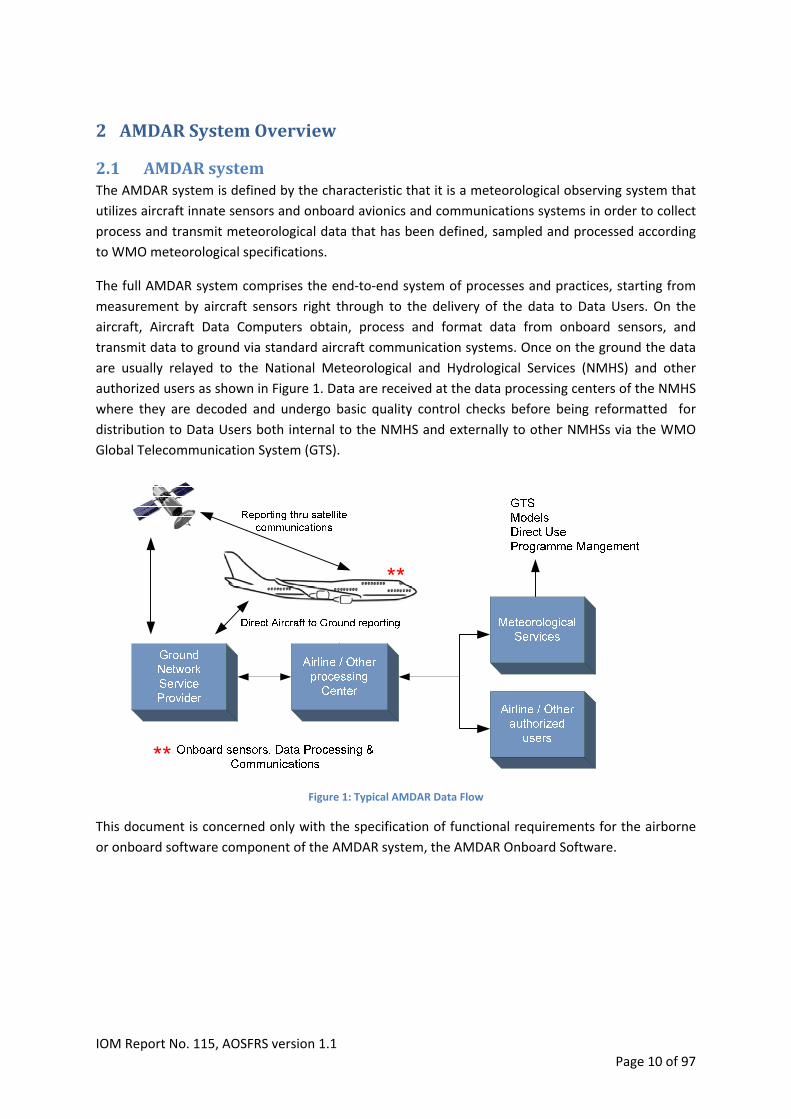
The full AMDAR system comprises the end‐to‐end system of processes and practices, starting from
measurement by aircraft sensors right through to the delivery of the data to Data Users. On the
aircraft, Aircraft Data Computers obtain, process and format data from onboard sensors, and
transmit data to ground via standard aircraft communication systems. Once on the ground the data
are usually relayed to the National Meteorological and Hydrological Services (NMHS) and other
authorized users as shown in Figure 1. Data are received at the data processing centers of the NMHS
where they are decoded and undergo basic quality control checks before being reformatted for
distribution to Data Users both internal to the NMHS and externally to other NMHSs via the WMO
Global Telecommunication System (GTS).
Figure 1: Typical AMDAR Data Flow
This document is concerned only with the specification of functional requirements for the airborne
or onboard software component of the AMDAR system, the AMDAR Onboard Software.
IOM Report No. 115, AOSFRS version 1.1 Page 10 of 97

IOM Report No. 115, AOSFRS version 1.1 Page 11 of 97
2.2 AMDAROnboardComponentoftheAMDARSystemThe purpose of the airborne part of the AMDAR onboard system is to collect, process and transmit meteorological data from sensors onboard the aircraft. To meet this purpose, AMDAR relies on the availability of onboard data acquisition systems that are
capable of being programmed to perform the required functions through the implementation of the
AMDAR Onboard Software, as specified within this document. Therefore, the first and most
fundamental requirement of the AMDAR Onboard System is that the aircraft must have a Data
Acquisition System (DAS) that is programmable and supports interfacing to all the required data
inputs and to the aircraft communications system.
Figure2 shows schematically the principal data sources feeding into a Flight Management System
and together forming the DAS. Note that the configurations and availability of systems vary widely
between aircraft models and airline fleets.
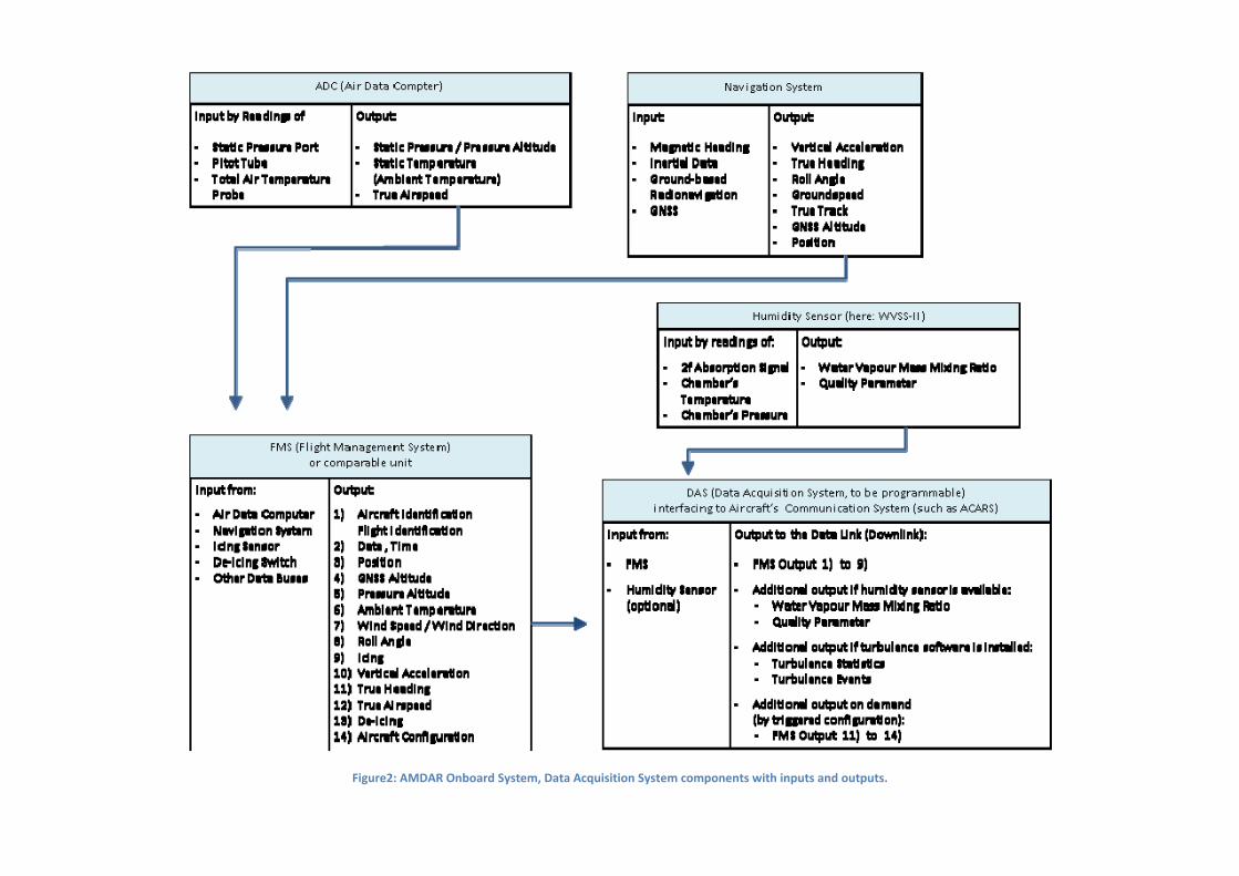
Figure2: AMDAR Onboard System, Data Acquisition System components with inputs and outputs.

Typical inputs to the DAS are, for example, Pressure Altitude, Static Air Pressure, Wind Speed, Wind
Direction and others. These input parameters are processed by the AMDAR Onboard Software
according to predefined sampling frequencies and the resulting data variables are stored as
meteorological “Observations”. Then, depending on the communications system used and
requirements associated with message costs and efficiency, data latency, phase of flight and other
parameters, when the required number of observations has been obtained, they are written to a
standardized message that is subsequently sent to the ground.
By taking advantage of two‐way aircraft‐to‐ground communications that are often available with
modern aircraft avionics and communications systems, it is possible to facilitate modification of
AMDAR Onboard Software program parameters via commands embedded within uplink messages,
which are usually compiled and sent by automated, ground‐based control systems in near real‐time.
This process is known as “AMDAR data optimization”. AMDAR optimization systems allow NMHS and
airlines to manage data volumes by avoiding redundant observations and messages through real‐
time AMDAR software modification either prior to or during aircraft flight and on an automated,
flight‐by‐flight basis.
The end result of the AMDAR Onboard Component and the AMDAR Onboard Software is the
production of the AMDAR messages containing the meteorological observations. These messages
are transmitted to the ground by suitable data link communication systems and relayed by aviation
Data Service Providers to the NMHS. The contents of the messages are processed and the data are
ingested into meteorological databases and applications.
2.3 OtherSpecificationsAt the current time, the AMDAR Observing System utilizes the ACARS communications standards
and message protocols for the transmission of AMDAR data from the aircraft to ground and for
ground‐based message relay. ACARS is short for Aircraft Communications Addressing and Reporting
System and is a digital data link system for transmission of short, relatively simple telex format
messages between aircraft and ground stations via radio or satellite. The protocol was designed by
Aeronautical Radio, Incorporated (ARINC). For more information on ACARS see ARINC618‐6
appendix B
AMDAR takes advantage of the free text area available within ACARS messages and so, theoretically,
there is no need to maintain a specification of AMDAR message formats within the ARINC ACARS
standards. Therefore, there are many possible format specifications for meteorological messages
from aircraft using ACARS. However, in order to avoid the proliferation of data formats and reduce
the overheads and complexity for compliance by ground processing systems it is important to
minimize the number of standards and protocols in use. This document provides a functional
requirements specification that will be known as the AMDAR Onboard Software (AOS) Functional
Requirements Specification (AOSFRS). This specification is based on the ASDAR Specification2, the E‐
2 Software Requirements Specification for the ASDAR Project, Issue 3, Matra Marconi Space UK Limited,
October 1994 (reference 1163‐00016‐44‐4).
AMDAR AAA Version 2.0 Specification (AAA V2)3and the AMDAR AAA Version 3.0 specification (AAA
V3)4. All information in this document supersedes the previously mentioned documents.
Some information in this document is derived from ARINC specification 620‐7 (ARINC 620)
(meteorological report version 1 thru 5). The ARINC 620 specification however is not superseded by
this document.
Since most meteorological messages share a common approach to processing, triggering and
transmitting data it is possible to use this specification in conjunction with other specifications. In
particular, the ARINC 620 Meteorological Report specification is a recognized standard for AMDAR
and it is therefore feasible and acceptable to specify that particular downlink format standard as an
alternative to those specified within this document, although it is suggested that using the
recommended message formats provided within the appendices to this specification will provide
communications efficiency dividends over the ARINC 620‐7 specified formats.
It is expected that ARINC 620 Supplement 8 will in fact define the downlink and uplink formats for
Meteorological Report version 6, which will reference and closely align with AOSFRS version 1.1
(this version).
The following section describes the similarities and differences between the ARINC 620
meteorological report specification, specifically versions 4 and 5, and AOSFRS (this document).
2.3.1 ARINC620versusthisdocumentAlthough a lot of commonalities exist between the ARINC 620 Meteorological Report (versions 1 to
5) and AOSFRS, there are some differences between the two. This paragraph may provide the reader
a better understanding of those similarities and differences. The WMO Expert Team on Aircraft‐
Based Observing Systems (ET‐ABO) recommends that the latest versions of both the AOSFRS and the
ARINC 620 Meteorological Report provide the most efficient and preferred standard for AMDAR
onboard software functionality.
Data Acquisition Acquisition of data depends on the systems installed onboard and is independent of the
specification. What matters for both specifications is that an interface exists to the best quality data
source.
Data Handling ARINC 620 describes how to handle and derive parameters in notes that are presented with the
downlink and uplink formats but it does not specify how to detect and handle invalid data. AOSFRS
describes requirements for data handling, validation and derivation of parameters in detail.
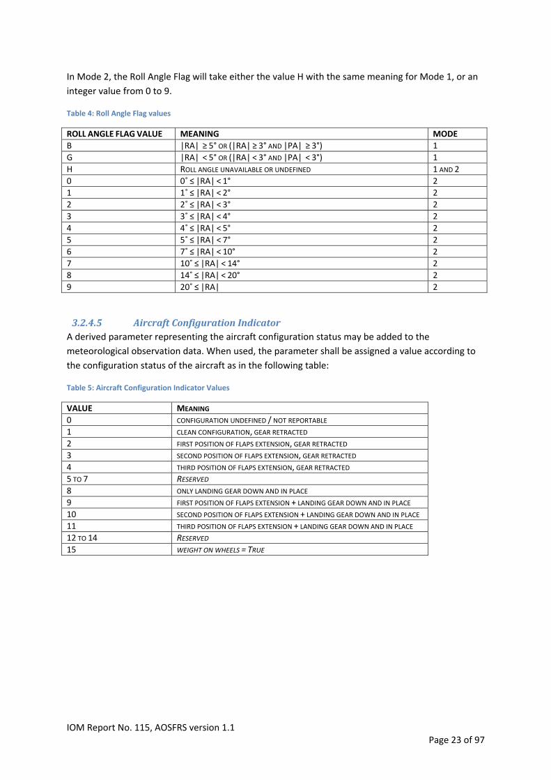
Phase of flight AOSFRS specifies conditions that determine the phase of flight for the weather message. ARINC 620
uses these phases of flight as well but other than for the time based scheme, does not provide clear
conditions to determine these.
3 EUMETNET AMDAR AAA AMDAR Software Developments – Technical Specification, Version 2, 1 August 2000.
4 PROGRAM OPERATIONS AND STANDARDS OBSERVATIONS SPECIFICATION 2006‐1, AMDAR AAA Version 3.0 Software Requirements Specification, 23 November 2006
IOM Report No. 115, AOSFRS version 1.1 Page 14 of 97

AMDAR observations Both specifications describe conditions when to trigger and store a meteorological observation. The
conditions are the same in both specifications. ARINC 620 refers to phase of flight and series, where
the term series refers to the observation contents and format for that particular phase of flight.
AOSFRS only refers to when an observation needs to be triggered and stored; the contents and
format are dealt with separately and are independent of the phase of flight.
Message format ARINC620 provides specific downlink formats for each phase of flight (series). AOSFRS uses only one
downlink format, regardless of the phase of flight.
ARINC 620 specifies 5 versions for the Meteorological Report to choose from. The message format
and content depends on the version chosen and is largely fixed in terms of content and parameter
composition, with unavailable parameters (e.g. water vapor is currently not available from the
majority of AMDAR aircraft) transmitted as “blank space”. AOSFRS specifies one basic format as a
minimum requirement and allows the addition of parameters in any sequence desired. The benefit
of the latter is that communications costs can be reduced and minimized by transmitting required
parameters and characters only. If only the most basic meteorological data were available or
required, utilization of the AOSFRS format would require 40% less characters than ARINC 620
(version 5).
Message Transmission Both specifications specify messages to be transmitted to the ground as soon as they are complete.
AOSFRS also specifies what to do with incomplete reports.
Software Configuration Control Both specifications provide information on how to configure the software so that reporting behavior
can be altered. ARINC 620 specifies fixed uplink formats with all the necessary configuration
parameters.
AOSFRS specifies the items that need to be configurable and does not provide a fixed format for
uplinks. As an alternative to uplinks, AOSFRS specifies that the configuration can also be changed
through flight deck interfaces and/or code changes. This allows for more flexibility for
implementation of the specification within different avionics systems.
AMDAR Optimization Message Both specifications mention an AMDAR optimization message. ARINC620 refers to the contents of
the configuration uplinks where in fact it is a downlink message telling the operator what aircraft is
leaving a gate at airport X to fly to airport Y.
Configuration Message Both specifications describe a means to retrieve information on the status/contents for all
configurable parameters; the information request and format differ.
Data Compression Both documents describe the same base‐40 data compression technique.
IOM Report No. 115, AOSFRS version 1.1 Page 15 of 97

2.4 FurtherReadingA detailed description of the AMDAR system is given in the Aircraft Meteorological Data Relay
(AMDAR) Reference Manual (WMO‐No 958) available from the World Meteorological Organization,
Geneva, Switzerland:
http://www.wmo.int/amdar/Publications/AMDAR_Reference_Manual_2003.pdf
and in the WMO GUIDE TO METEOROLOGICAL INSTRUMENTS AND METHODS OF OBSERVATION,
Part 2, Chapter 3, Aircraft Observations:
http://www.wmo.int/pages/prog/www/IMOP/CIMO‐Guide.html
IOM Report No. 115, AOSFRS version 1.1 Page 16 of 97
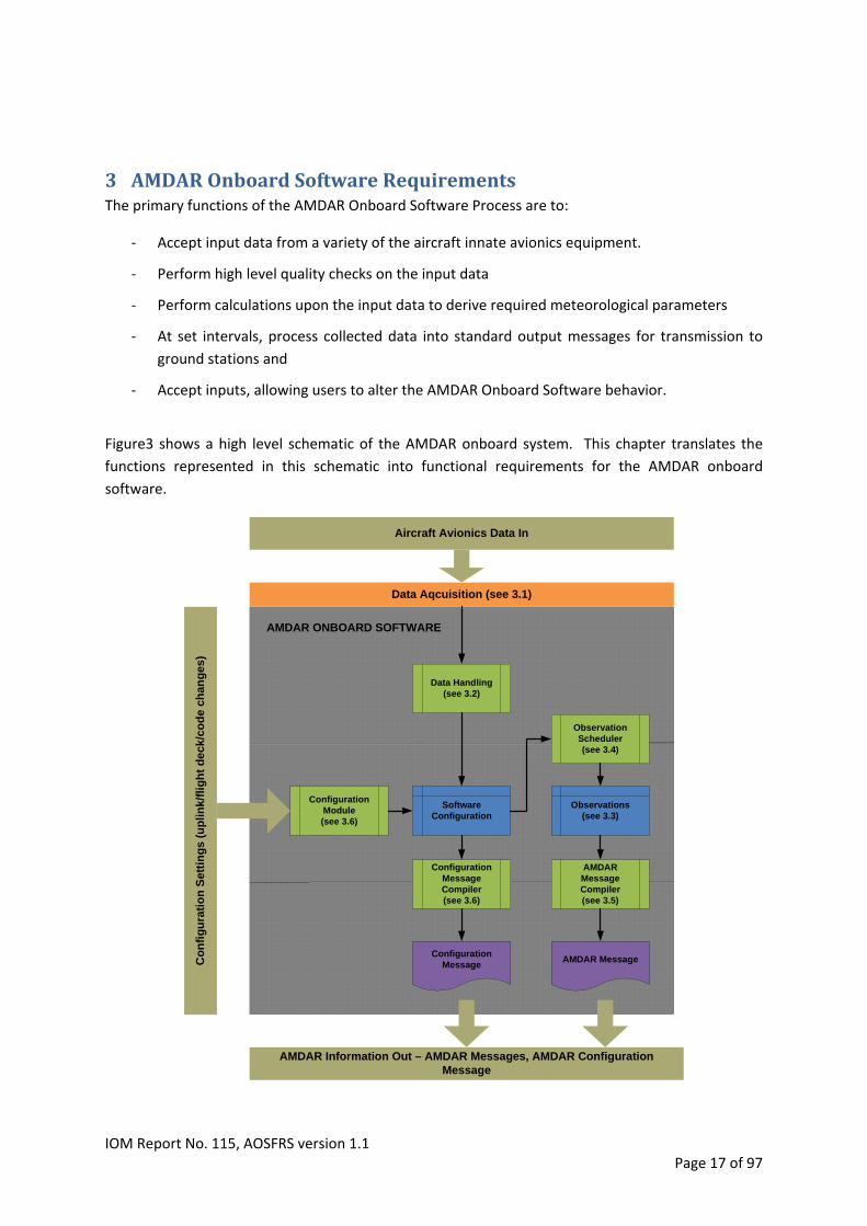
3 AMDAROnboardSoftwareRequirementsThe primary functions of the AMDAR Onboard Software Process are to:
‐ Accept input data from a variety of the aircraft innate avionics equipment.
‐ Perform high level quality checks on the input data
‐ Perform calculations upon the input data to derive required meteorological parameters
‐ At set intervals, process collected data into standard output messages for transmission to
ground stations and
‐ Accept inputs, allowing users to alter the AMDAR Onboard Software behavior.
Figure3 shows a high level schematic of the AMDAR onboard system. This chapter translates the
functions represented in this schematic into functional requirements for the AMDAR onboard
software.
Data Handling(see 3.2)
AMDAR Message Compiler(see 3.5)
AMDAR MessageConfiguration
Message
Software Configuration
ConfigurationModule(see 3.6)
Configuration Message Compiler(see 3.6)
Observations(see 3.3)
Observation Scheduler(see 3.4)
Aircraft Avionics Data In
AMDAR Information Out – AMDAR Messages, AMDAR Configuration Message
Co
nfi
gu
rati
on
Set
tin
gs
(up
lin
k/fl
igh
t d
eck
/co
de
chan
ges
)
Data Aqcuisition (see 3.1)
AMDAR ONBOARD SOFTWARE
IOM Report No. 115, AOSFRS version 1.1 Page 17 of 97

Figure3: AMDAR Onboard Component of the AMDAR System and the schematic functionality of the AMDAR Onboard Software.
3.1 DataAcquisitionThe onboard Data Acquisition System (DAS) shall provide a data interface to the highest quality data
sources available from the aircraft. In case the direct source is not available to the acquisition system
it is acceptable to use an indirect source, as long as the quality of the data is maintained. For
example, the latitude is derived from the inertial reference system but this source is not connected
directly to the AOS. Latitude is however transmitted to the Flight Management Computer (FMC) and
this source is available to the AOS. As long as data quality is maintained the latitude can be obtained
from the FMC instead of directly from the Inertial Reference System (IRS).
The source data for meteorological observations require significant correction and complex
processing to yield meteorological measurements that are representative of the free air‐stream in
the aircraft vicinity. A full description of all the processes involved is beyond the scope of this
document. An outline of the principles and references for further reading are provided in the WMO
Guide to Meteorological Instruments and Methods of Observation, , part II chapter three5.
Figure2 in Section 2.2 shows schematically the principal data sources feeding into a Flight
Management System and together forming the DAS. Note that the configurations and availability of
systems varies widely between aircraft models and airline fleets.
The tables below provide the input signals to be acquired. Distinction is made between signals that
shall be acquired (Table 1), should be acquired (Table 2) and signals that are optional (Table 3).
If any of the parameters in Table 1 are not able to be acquired or derived from an avionics system to
the required performance specifications, then the AOS application would be deemed to not meet
required standards and should not be implemented.
If the avionics system and the CPU allowance for the AOS make it permissible and possible,
parameters in Table 2 and Table 3 may be implemented, assuming that the appropriate
corresponding requirements for alteration to downlink format are implemented and that the format
alteration is able to be recognized and decoded by a ground processing system. Such a requirement
and its implementation would require the utilization of the recommended downlink format defined
within Appendix A.
5 Available at: http://www.wmo.int/pages/prog/www/IMOP/CIMO‐Guide.html
IOM Report No. 115, AOSFRS version 1.1 Page 18 of 97

Table 1: Input Signals ‐ Required
UNIT RESOLUTION RANGE ACQ RATE DESCRIPTION
PREFERRED MAX
INT N/A N/A N/A N/A AIRCRAFT ID
DISCRETE N/A N/A 1HZ 1HZ AIR/GROUND SWITCH OR WEIGHT ON WHEELS
KN 1 0 TO 800 1HZ 2HZ COMPUTED AIR SPEED
DAY OF
MONTH 1
0 ‐ 31 1HZ 4HZ DATE ‐ DAY
HOURS 1 00 ‐ 23 1HZ 2HZ GMT ‐ HOURS
MINUTES 1 00 ‐ 59 1HZ 2HZ GMT ‐ MINUTES
SECONDS 1 00 ‐ 59 1HZ 2HZ GMT ‐ SECONDS
DEGREES 0.002 90S TO 90N 1HZ 4HZ LATITUDE
DEGREES 0.002 180E TO 180W 1HZ 4HZ LONGITUDE
FT 1 ‐1000 TO 50000 1HZ 2HZ PRESSURE ALTITUDE IN ICAO STANDARD ATMOSPHERE
°C 0.1 ‐99.9 TO +99.9 1HZ 2HZ STATIC AIR TEMPERATURE
STATIC PRESSURE NOTE 1) HPA (MBAR) 1 900 TO 1050 1HZ 1HZ
DEGREES 1 0 TO 359 1HZ 2HZ WIND DIRECTION TRUE
KN 1 0 TO 800 1HZ 2HZ WIND SPEED
DEGREES 1 ‐180 TO 180 1HZ 1HZ ROLL ANGLE
DEGREES 1 ‐90 TO 90 1HZ 1HZ PITCH ANGLE
Note 1: If static pressure is not available from the aircraft systems it can be calculated from pressure altitude
For PALT equal to or less than 36 089 ft., static pressure (SP) is related to PALT (ft) by the following expression:
SP (hPa) = 1013.25 [1 – 10‐6 x 6.8756 x PALT]5.2559
If PALT is greater than 36 089 ft, static pressure is given by: SP (hPa) = 226.32 x exp(‐(PALT‐36089)/20806)
Table 2: Input Signals ‐ Recommended
DESCRIPTION UNIT RESOLUTION RANGE ACQ RATE
PREFERRED MAX
DEPARTURE STATION CHAR N/A N/A N/A N/A
DESTINATION STATION CHAR N/A N/A N/A N/A
VERTICAL SPEEDNOTE 2)
FT/MIN 1 ‐2000 TO 2000 1HZ 1HZ
GROSS WEIGHT KG 1 N/A 1HZ 1HZ
VERTICAL ACCELERATION G 0.001 ‐3 TO +6 8HZ 16HZ
Note 2: Vertical speed is used in phase of flight determination. Vertical speed may be derived from altitude rate of
change
IOM Report No. 115, AOSFRS version 1.1 Page 19 of 97

Table 3: Input Signals ‐ Optional
DESCRIPTION UNIT RESOLUTION RANGE ACQ RATE
PREFERRED MAX
WATER VAPOR DATA NOTE 3 1HZ 4HZ
EDR (EDDY DISSIPATION RATE) NOTE 4 N/A N/A 1 MINUTE N/A
ICING DATANOTE 5 )
DISCRETE N/A N/A 1HZ 4HZ
ANTI‐ICE DISCRETE N/A N/A 1HZ 1HZ
AIRCRAFT CONFIGURATION INDICATORNOTE 6 ) DISCRETE N/A 0 TO 15 1HZ 4HZ
FLAPS DEGREES 1 0 TO 50 1HZ 4HZ
GEAR DOWN/UP DISCRETE N/A N/A 1HZ 2HZ
GNSS ALTITUDE FT 1 ‐1000 TO 50000 1HZ 1HZ
GROUNDSPEED KN 1 0 TO 800 1HZ 2HZ
TRUE TRACK DEGREES 0.1 0.0 TO 359.9 1HZ 2HZ
DEGREES 0.1 0.0 TO 359.9 1HZ 2HZ TRUE HEADING
TRUE AIRSPEED KN 1 0 TO 800 1HZ 2HZ
Note 3: If available, water Vapor can be measured and reported either as mixing ratio or relative humidity, depending on the type of sensor employed. For more information see appendix C.2. Note 4: If available, Eddy Dissipation Rate (EDR) can be measured and reported. For more information see section 3.2.4.2. Note 5:
Icing will be reported as value 1 when the aircraft icing sensor indicates no ice accretion, as value 2 when the sensor
indicates ice accretion is occurring, and as value 0 when the status of icing is not able to be determined (note requires
separate system installed).
Note 6:
Aircraft Configuration Indicator is defined within section 3.2.4.5.
3.2 DataHandling
3.2.1 DataacquisitionrateInput data can be acquired at different acquisition rates. For instance, data can be acquired 8 times
per second but it is also possible to have parameters acquired once every two or four seconds.
Following rules describe how to handle acquisition rates.
1. For input data acquired once per second, no special rule applies.
2. For input data acquired more than once per second, the last valid sample within that second
shall be used.
3. For input data acquired less than once per second, the last valid sample shall be used.
3.2.2 DataValidationInput Data should only be used when:
1. It is validated using applicable avionics validation standards and,
2. It passes the out of Range check. Input data values should be checked against the range
given in Table 1, Table 2 and Table 3. When the input data value falls outside this range it is
considered invalid.
Data that is invalid shall not be used in any calculation. Observations shall continue but invalid data
shall be either not reported, or masked as specified, usually with a solidi (‘/’).Some indication should
IOM Report No. 115, AOSFRS version 1.1 Page 20 of 97
be provided within AMDAR observations and reports when the parameters, particularly
meteorological parameters, have been invalidated as this helps NMHS AMDAR program managers
determine the existence of possible onboard faults or systemic issues.
3.2.3 DataSmoothingWhile previous specifications for the AOS have incorporated algorithms for smoothing or averaging
data parameters, this practice is not recommended without clear scientifically based justification.
Smoothing or averaging should not be implemented. Therefore, unless specifically stated, all
reported parameter values shall be obtained or be calculated from the highest frequency
instantaneous sample available from the relevant data bus, closest to the observation time and
subject to the Data Validation requirements specified in section 3.2.2.
3.2.4 DerivedParameters
3.2.4.1 PhaseofFlightAMDAR observation intervals should be linked to aircraft flight phase. The following phases of flight
conditions should be recognized:
a) Ground
b) Ascent
c) Level flight (or Cruise or En‐route)
d) Descent
An assessment of the Phase of Flight should be made at regular one second intervals. The aircraft
will be considered to occupy one of the phases of flight at any time, but transition from one phase to
another does not necessarily follow the order listed above, except that Phase Ascent shall always
ase Gro 60 seconds minimum. follow Ph und for
3.2.4.1.1 GroundThe aircraft is considered on the ground when it is not in one of the reporting flight modes (ascent,
en‐route or descent). The aircraft is in ground phase when:
1. Computed Airspeed is equal to or less than 100 knots or Computed Airspeed data is invalid;
and
2. Air/ground switch indicates ground or weight on wheels is true
During th e the so
3.2.4.1.2 Ascent
is phas ftware is active and processes data but no observations are made.
The aircraft is in ascent when:
1. Computed Airspeed > 100 kn; and 2. Altitude Rate > +200 feet/min; and 3. a. Pressure based scheme: Pressure Altitude <= Top of Climb (see Table 9); or
b. Time based scheme: Flight time since take‐off <= Ascent Total Duration (see Table 9) When As llows the g
3.2.4.1.3 En‐Route
cent fo round phase, Ascent shall be held for a minimum of 60 seconds.
The aircraft is in en‐route when:
IOM Report No. 115, AOSFRS version 1.1 Page 21 of 97

1. Computed Airspeed > 100 kn; and
2. a. Pressure based scheme: Pressure Altitude > Top of Climb (see Table 9); or
. Time eme: Flight time since take‐off > Ascent total duration (see Table 9) b based sch
3.2.4.1.4 DescentThe aircraft is in descent when:
1. Computed Airspeed > 100 kn; and
2. Altitude Rate < ‐200 feet/min ; and
3. Pressure Altitude < Top of Descent (see Table 11)
3.2.4.2 TurbulenceMetricA turbulence metric should be derived and reported within the AMDAR observation. Metrics that
should be used are:
1. Eddy Dissipation Rate (EDR)and/or
2. Derived Equivalent Vertical Gust (DEVG)
EDR is the preferred metric to be reported by AMDAR and the AOS should incorporate the reporting
of both a routine or “Heartbeat” EDR observation and also reporting of the 3 event‐based
observations that are “triggered” based on the EDR 1‐minute variables.
This document does not specify the requirements for calculation and provision of the EDR 1‐minute
variables but relies on the specification referenced within Appendix C.1.2.
For details on EDR calculation and the AMDAR reporting algorithm, see Appendix C.1.2
For recommended reporting formats incorporating EDR see Appendix A.
For details on DEVG calculation see appendix C.1.1
3.2.4.3 WaterVapor/RelativeHumidity/DewPointWater Vapor/ Relative humidity or Dew Point data may be reported within the AMDAR observation.
Details for this parameter can be found in appendix C.2
Note that this parameter requires an appropriate sensor to be installed on the aircraft
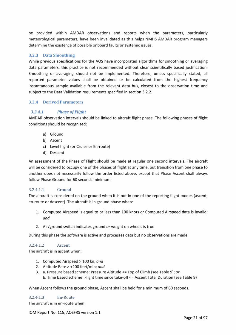
3.2.4.4 RollAngleFlagA Roll Angle Flag should be reported within the AMDAR observation.
The flag is used in one of two modes:
Mode 1: either as a quality indicator for wind speed and direction based on the aircraft roll angle
(RA) and pitch angle (PA) or,
Mode 2: to provide an indication of which range bin the aircraft roll angle value lies within.
In Mode 1, the Roll Angle Flag will take the value B, G or H, with the corresponding meaning
provided in the table below.
IOM Report No. 115, AOSFRS version 1.1 Page 22 of 97
In Mode 2, the Roll Angle Flag will take either the value H with the same meaning for Mode 1, or an
integer value from 0 to 9.
Table 4: Roll Angle Flag values
ROLL ANGLE FLAG VALUE MEANING MODE
B |RA| ≥ 5° OR (|RA| ≥ 3° AND |PA| ≥ 3°) 1
G |RA| < 5° OR (|RA| < 3° AND |PA| < 3°) 1
H ROLL ANGLE UNAVAILABLE OR UNDEFINED 1 AND 2
0 0˚ ≤ |RA| < 1° 2
1 1˚ ≤ |RA| < 2° 2
2 2˚ ≤ |RA| < 3° 2
3 3˚ ≤ |RA| < 4° 2
4 4˚ ≤ |RA| < 5° 2
5 5˚ ≤ |RA| < 7° 2
6 7˚ ≤ |RA| < 10° 2
7 10˚ ≤ |RA| < 14° 2
8 14˚ ≤ |RA| < 20° 2
9 20˚ ≤ |RA| 2
3.2.4.5 AircraftConfigurationIndicatorA derived parameter representing the aircraft configuration status may be added to the
meteorological observation data. When used, the parameter shall be assigned a value according to
the configuration status of the aircraft as in the following table:
Table 5: Aircraft Configuration Indicator Values
VALUE MEANING
0 CONFIGURATION UNDEFINED / NOT REPORTABLE
1 CLEAN CONFIGURATION, GEAR RETRACTED
2 FIRST POSITION OF FLAPS EXTENSION, GEAR RETRACTED
3 SECOND POSITION OF FLAPS EXTENSION, GEAR RETRACTED
4 THIRD POSITION OF FLAPS EXTENSION, GEAR RETRACTED
RESERVED 5 TO 7
8 ONLY LANDING GEAR DOWN AND IN PLACE
9 FIRST POSITION OF FLAPS EXTENSION + LANDING GEAR DOWN AND IN PLACE
10 SECOND POSITION OF FLAPS EXTENSION + LANDING GEAR DOWN AND IN PLACE
11 THIRD POSITION OF FLAPS EXTENSION + LANDING GEAR DOWN AND IN PLACE
RESERVED 12 TO 14
15 WEIGHT ON WHEELS = TRUE
IOM Report No. 115, AOSFRS version 1.1 Page 23 of 97

3.3 AMDARObservationsA crucial function of the AMDAR software is to trigger and store observations. An Observation is a
single consistent set of (calculated) parameter values at a point in space and time.
Observations are made during following phases of flight only: ‐ Ascent ‐ En‐route (or Cruise) ‐ Descent
Observations shall be made either:
1) When a pre‐set static pressure level is reached (Pressure based scheme, default) 2) When a pre‐set time period has elapsed (Time Based scheme)
The software shall be capable of switching between either scheme but only one scheme shall be
active at any given time.
Observations shall be stored in a dedicated area of memory until required.
There are several types of AMDAR Observations defined that, when reported, shall be indicated and
identifiable within AMDAR reports, see following page:
Following Observation Types are defined
ASCENT – INITIAL
ASCENT
ASCENT ROUTINE
EN‐ROUTE
MAXIMUM WIND
DESCENT
DESCENT ROUTINE
EDR ROUTINE
TOUCH‐DOWN
Regardless of observation type, the following elements should be reported and form the Basic
Observation Sequence:
IOM Report No. 115, AOSFRS version 1.1 Page 24 of 97
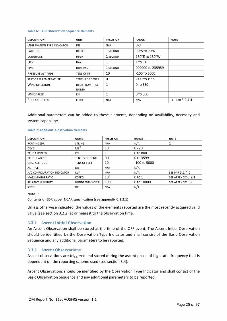
Table 6: Basic Observation Sequence elements
DESCRIPTION UNIT PRECISION RANGE NOTE
OBSERVATION TYPE INDICATOR INT N/A 0‐9
DEGR 1 SECOND 90S TO 90N LATITUDE
DEGR 1 SECOND 180E TO 180W LONGITUDE
DAY DAY 1 1 TO 31
TIME HHMMSS 1 SECOND 000000 TO 235959
PRESSURE ALTITUDE TENS OF FT 10 ‐100 TO 5000
STATIC AIR TEMPERATURE TENTHS OF DEGR C 0.1 ‐999 TO +999
DEGR FROM TRUE
NORTH 1 0 TO 360 WIND DIRECTION
WIND SPEED KN 1 0 TO 800
ROLL ANGLE FLAG CHAR N/A N/A SEE PAR 3.2.4.4
Additional parameters can be added to these elements, depending on availability, necessity and
system capability:
Table 7: Additional Observation elements
DESCRIPTION UNITS PRECISION RANGE NOTE
ROUTINE EDR STRING N/A N/A 1
MS‐1 10 0 ‐ 20 DEVG
TRUE AIRSPEED KN 1 0 TO 800
TRUE HEADING TENTHS OF DEGR 0.1 0 TO 3599
GNSS ALTITUDE TENS OF FEET 10 ‐100 TO 5000
ANTI‐ICE DIS N/A N/A
A/C CONFIGURATION INDICATOR N/A N/A N/A SEE PAR 3.2.4.5
KG/KG 106 0 TO 1 SEE APPENDIX C.2.1 MASS MIXING RATIO
RELATIVE HUMIDITY HUNDREDTHS OF % 100 0 TO 10000 SEE APPENDIX C.2
ICING DIS N/A N/A
Note 1:
Contents of EDR as per NCAR specification (see appendix C.1.2.1)
Unless otherwise indicated, the values of the elements reported are the most recently acquired valid
value (see section 3.2.2) at or nearest to the observation time.
3.3.1 AscentInitialObservationAn Ascent Observation shall be stored at the time of the OFF event. The Ascent Initial Observation
should be identified by the Observation Type Indicator and shall consist of the Basic Observation
Sequence and any additional parameters to be reported.
3.3.2 AscentObservationsAscent observations are triggered and stored during the ascent phase of flight at a frequency that is
dependent on the reporting scheme used (see section 3.4).
Ascent Observations should be identified by the Observation Type Indicator and shall consist of the
Basic Observation Sequence and any additional parameters to be reported.
IOM Report No. 115, AOSFRS version 1.1 Page 25 of 97
3.3.3 DescentObservationsDescent observations are triggered and stored during the descent phase of flight at a frequency that
is dependent on the reporting scheme used (see section 3.4).
Descent observations should be identified by the Observation Type Indicator and shall consist of the
Basic Observation Sequence and any additional parameters to be reported.
3.3.4 RoutineObservationsRoutine Observations are made at set and configurable time intervals and, when enabled, should be
made during all phases of flight.
Routine Observations should be identified by the Observation Type Indicator and shall consist of the
Basic Observation Sequence and any additional parameters to be reported.
3.3.4.1 AscentRoutineObservationsAscent Routine Observations are Routine Observations made at set time intervals during the ascent
phase of flight. These observations may be configured to be reported only when a pressure‐based
reporting scheme is in use so as to ensure data is still collected at regular time intervals in the case
where the aircraft levels off during ascent and static pressure triggering cannot be used since the
static pressure does not change during level flight. It will also ensure that observations are taken if
the aircraft does not reach the set altitude for top‐of‐climb.
Ascent Routine Observations should be identified by the Observation Type Indicator and shall consist
of the Basic Observation Sequence and any additional parameters to be reported.
3.3.4.2 En‐routeRoutineObservationsEn‐route Routine Observations are Routine Observations that are made at set time intervals during
the En‐route flight phase and are independent of whether the Pressure Based or Time Based scheme
is utilized for the acquisition of Ascent and Descent Observations.
Routine Observations should be identified by the Observation Type Indicator and shall consist of the
Basic Observation Sequence and any additional parameters to be reported.
3.3.4.3 DescentRoutineObservationsDescent Routine observations are Routine Observations made at set time intervals during the
descent phase of flight. These observations may be configured to be reported only when a pressure‐
based reporting scheme is in use so as to ensure data is still collected at regular time intervals in the
case where the aircraft levels off during descent and static pressure triggering cannot be used since
the static pressure does not change during level flight.
Descent Routine Observations should be identified by the Observation Type Indicator and shall
consist of the Basic Observation Sequence and any additional parameters to be reported.
3.3.4.4 MaximumWindObservationThe Maximum Wind Observation is a special AMDAR observation that is triggered to be reported
when the highest wind speed measured between a sequential pair of routine observations meets
the criteria below. This observation is required to aid in locating jet stream cores and should be
made in en‐route flight phase only. The Maximum wind is derived according to the following criteria:
IOM Report No. 115, AOSFRS version 1.1 Page 26 of 97

1. Observations of wind speed maxima will only be reported when the ambient pressure is
lower than 600 hPa, and
2. The aircraft is in en‐route, and
3. The wind speed exceeds 60 knots absolute, and
4. The wind speed exceeds by 10 knots or more the value observed at the previous routine
observation, and
5. The wind speed exceeds by 10 knots or more the value observed at the subsequent routine
observation.
The Maximum Wind option provides an additional observation that is taken at the time of
occurrence of the peak wind measurement.
The Maximum Wind Observation should be identified by the Observation Type Indicator and shall
consist of the Basic Observation Sequence and any additional parameters to be reported at the time
of the maximum wind measurement.
3.3.5 EDRRoutineObservationsMean and peak turbulence intensity (EDR –eddy dissipation rate) is calculated for each minute in
flight. At regular and configurable time intervals an observation is stored that consists of the normal
observation parameters, any additional parameters to be reported, concatenated with the EDR
variables.
For full details on EDR calculation and reporting see appendix C.1.2
EDR Routine Observations should be identified by the Observation Type Indicator.
3.3.6 Touch‐downObservationThe Touch‐down Observation shall be stored at the time of the ON event.
Touch‐down Observations should be identified by the Observation Type Indicator and shall consist of
the Basic Observation Sequence and any additional parameters to be reported.
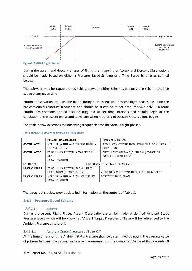
3.4 FlightPhasesandReportingSchemesThe frequency at which most AMDAR observations are made depends on the phase of flight the
aircraft is in.
The figure below illustrates how AMDAR Onboard Software should differentiate between the various
flight phases.
IOM Report No. 115, AOSFRS version 1.1 Page 27 of 97
Ascent Part 1
Ascent Part 2
En-routeDescent
Part1Descent Part 2
Top of Climb
100hPa below Static pressureat take-off
Top of Descent
100hPa below Static pressure at touchdown
Figure4: AMDAR flight phases
During the ascent and descent phases of flight, the triggering of Ascent and Descent Observations
should be made based on either a Pressure Based Scheme or a Time Based Scheme as defined
below.
The software may be capable of switching between either schemes but only one scheme shall be
active at any given time.
Routine observations can also be made during both ascent and descent flight phases based on the
pre‐configured reporting frequency and should be triggered at set time intervals only. En‐route
Routine Observations should also be triggered at set time intervals and should begin at the
conclusion of the ascent phase and terminate when reporting of Descent Observations begins.
The table below describes the observing frequencies for the various flight phases.
Table 8: AMDAR observing Interval by flight phase
PRESSURE BASED SCHEME TIME BASED SCHEME
ASCENT PART 1 5 OR 10 HPA INTERVALS FOR FIRST 100 HPA ( DEFAULT 10 HPA)
3 TO 20SECS INTERVALS (DEFAULT 6) FOR 30 TO 200SECS (DEFAULT 90)
ASCENT PART 2 25 OR 50 HPA INTERVALS ABOVE FIRST 100 HPA (DEFAULT 50 HPA)
20 TO 60SECS INTERVALS (DEFAULT 20) FOR 490 TO 1050SECS (DEFAULT 510)
EN‐ROUTE: 1 TO 60 MINUTE INTERVALS (DEFAULT 7)
DESCENT PART 1 25 OR 50 HPA INTERVALS FROM TOD TO
LAST 100 HPA (DEFAULT 50 HPA)
5 OR 10 HPA INTERVALS FOR LAST 100 HPA (DEFAULT 10 HPA)
20 TO 300SECS INTERVALS (DEFAULT 40) FROM TOP OF
DESCENT TO TOUCHDOWN. DESCENT PART 2
The paragraphs below provide detailed information on the content of Table 8.
3.4.1 PressureBasedScheme
3.4.1.1 AscentDuring the Ascent Flight Phase, Ascent Observations shall be made at defined Ambient Static
Pressure levels which will be known as "Ascent Target Pressures". These will be referenced to the
PressurAmbient e at take‐off.
3.4.1.1.1 AmbientStaticPressureatTake‐OffAt the time of take‐off, the Ambient Static Pressure shall be determined by noting the average value
of p taken between the second successive measurement of the Computed Airspeed that exceeds 60
IOM Report No. 115, AOSFRS version 1.1 Page 28 of 97
knots and the second successive measurement of the Computed Airspeed that exceeds 90 knots.
The Ambient Static Pressure at take‐ off will be stored.
If the Computed Airspeed falls back below 60 knots before Ascent is entered, but after an Ambient
Static Pressure at take‐off value is stored, then the value stored shall be overwritten when the
d Airsp 90 knots. Compute eed next increases from 60 through
3.4.1.1.2 InitialAscentObservationAn initial Observation s
3.4.1.1.3 AscentPart1
Ascent hall be made and stored at the time of the OFF event (take‐off).
Ascent Observations shall be made when the Ambient Static Pressure first falls below the Ascent
Target Pressure. The first Ascent Target Pressure shall be the nearest multiple of 10 hPa (modifiable
to 5hPa) below the Ambient Static Pressure at take‐off. The next nine (modifiable to 19 if 5hPa is
used) Ascent Target Pressures shall follow at 10 hPa (modifiable to 5hPa) intervals decrementing
from the first Ascent Target Pressure level.
For interv duration value
3.4.1.1.4 AscentPart2
al and s see Table 9.
The eleventh (or twenty‐first) Ascent Target Pressure shall be the nearest multiple of 50 hPa
(modifiable to 25hPa) below the tenth (or twentieth) Ascent Target Pressure. The twelfth (or twenty‐
second) and subsequent Ascent Target Pressures shall follow at 50 hPa (modifiable to 25hPa)
intervals decrementing from the eleventh (or twenty‐first) Ascent Target Pressure. Observations will
continue at 50 hPa (modifiable to 25hPa) intervals throughout the remainder of the Ascent Phase.
The complete Ascent data profile will thus consist of ten observations at 10 hPa (or twenty at 5 hPa)
intervals over the first 100 hPa, and Observations at 50 hPa (or 25 hPa) intervals thereafter until the
Ascent is complete.
For interv duration values see Table 9.
3.4.1.1.5
al and
AscentRoutineObservationsRoutine observations shall be made at set time intervals during flight phase ascent. The interval
timer resets and commences following each observation. If no pressure level change is encountered
during the preset time interval, an observation is triggered and the timer is reset. The time interval is
the same as the en‐route observation time interval (see Table 10)
3.4.1.2 DescentDuring Phase of Flight Descent, Observations shall be made at defined Ambient Static Pressure
levels, which will be known as "Descent Target Pressures".
The first Descent Target Pressure shall be the first multiple of 50 hPa (modifiable to 25hPa) above
the pressure recorded when the Descent phase was established. Subsequent Descent Target
Pressures shall be at 50 hPa (modifiable to 25hPa) intervals. Observations shall be made when the
Ambient Static Pressure first rises above the Descent Target Pressure.
At and above 700 hPa the software shall, in addition to the continued formation of Observations at
50 hPa intervals, form Observations at 10 hPa intervals incrementing from 700 hPa. Only the ten
IOM Report No. 115, AOSFRS version 1.1 Page 29 of 97
most recent Observations at 10 hPa intervals are retained. This additional sampling shall continue
until the Descent is completed. In the event of the aircraft landing before a complete set of 50 hPa
(modifiable to 25hPa) observations have been made the message will be padded out with the “/“
character followed by a new message which contains the ten Observations made before touch‐
down. The complete set of Descent Observations is thus a series of observations at 50 hPa intervals,
augmented by a detailed vertical survey of the last 100 hPa in 10 hPa increments, which shall not
include repeats of observations at 50 hPa intervals.
For Top o nt and interval values see T
3.4.1.2.1
f Desce able 11.
Touch‐downObservationThe Touch‐Down observation should be made and stored before and as close as possible to the time
of the ON event.
Touch‐down Observations should be identified by the Observation Type Indicator and shall consist of
Observ al parameters to be reported. the Basic ation Sequence and any addition
3.4.1.2.2 DescentRoutineObservationsRoutine observations shall be made at set time intervals during flight phase descent. The interval
timer resets and commences following each observation. If no pressure level change is encountered
during the preset time interval, an observation is triggered and the timer is reset. The time interval is
the same as the en‐route observation time interval (see Table 10).
3.4.2 TimeBasedScheme
3.4.2.1 Ascent
3.4.2.1.1 InitialAscentObservationAn initial Observ
3.4.2.1.2 Part1
Ascent ation is triggered at the “OFF” event.
Following the Initial observation, observations are accumulated at set time intervals until the part #1
duration limit is reached, counted from the “OFF” event. For interval and duration values see Table
9.
3.4.2.1.3 Part2Observations are accumulated from the expiration of the Part #1 data acquisition period. Part #2
data observations are taken at set time intervals until the Ascent total duration limit is reached,
counted from the “OFF” event. For interval and duration values see Table 9.
3.4.2.2 DescentDescent data measurements begin at Top of Descent and are accumulated at a set time interval. Top
of Descent is modifiable.
For Top o nt and interval values see T
3.4.2.2.1 Touch‐downObservation
f Desce able 11.
An observation is stored as close as possible but before the aircraft touches down. This observation
is included as the last observation in the last descent message.
IOM Report No. 115, AOSFRS version 1.1 Page 30 of 97

3.5 MessageCompilation
3.5.1 ContentAMDAR Observations are collected and stored during flight. When a pre‐set or maximum allowable
number of observations are stored, a message shall be formed containing these observations. After
a message is transmitted, the observations can be discarded. The message shall provide at least the
following information:
‐ Identification as AMDAR data
‐ Software version indicator i.e. what specification it conforms to
‐ Reporting scheme (time‐based or pressure‐based)
‐ All required AMDAR Observations
‐ Any other information required to decode and reform data at the original and highest
quality possible.
The AMDAR onboard system shall be capable of transmitting AMDAR Observations to the ground
according to the Transmission Requirements below.
The AMDAR onboard system should be capable of transmitting the following messages:
AMDAR Optimization
AMDAR Status
3.5.2 FormatThe message format depends on the standard adopted. For AOSFRS (this document) see Appendix A.
3.5.2.1 ACARSmessages
When using ACARS, the AMDAR message format is bound to ACARS message protocol. This protocol does not impose any restrictions on the message format. For completeness a short description of the ACARS message block is provided below.
Most ACARS messages are only 100 to 200 characters in length. Such messages are made up of a one‐block transmission from (or to) the aircraft. One ACARS block is constrained to be no more than 220 characters within the body of the message. For downlink messages which are longer than 220 characters, the ACARS unit splits the message into multiple blocks, transmitting each block to the Remote Ground Station (RGS). There is a constraint that no message may be made up of more than 16 blocks. The RGS collects each block of such multi‐block messages until the complete message is received before processing and routing the message. ACARS also contains protocols to support a retry of failed messages.
3.5.3 TransmissionRequirements
The frequency of transmission of messages must take into account two factors:
1. It is critical to many meteorological applications, including weather forecasting and
Numerical Weather Prediction that Observations are made available to NMHSs as close
to “real‐time” as possible, particularly for Ascent and Descent flight phases; and,
2. Communications costs, particularly for air to ground, are relatively expensive and,
therefore, efficiency and economy in the content of messages is very important.
IOM Report No. 115, AOSFRS version 1.1 Page 31 of 97

Taking these factors into account, the following requirements specifications are made.
The transmission of messages should be structured so as to ensure that Ascent and Descent
Observations are available at the NMHS within 15 minutes.
Ideally, messages consisting solely of En‐route should be transmitted so as to ensure availability at
the NMHS within the minimum lapse time, taking into account communications costs, efficiency and
other factors such as availability of communications relay stations.
Messages that contain critical observations that have been identified as requiring immediate
transmission, for example, turbulence event based reports may require immediate transmission.
Regardless of the format, messages shall be sent to the ground as soon as they are complete via the
most reliable and efficient means possible.
Even if the message transmission method is subject to message volume or size restrictions, as is the
case for ACARS and the pre‐set number of observations has not been reached, pending messages
shall be sent immediately in situations outlined below:
1. Flight phase transitions. For example; the aircraft transitions from flight phase ascent to
flight phase en‐route, the pre‐set number of observations is ten but only five observations
are stored. In this case, a message shall be send with only five observations.
2. Reporting turned off by software control. For example; reporting during descent is turned on
initially. During descent, reporting is switched off by uplink command. At that time only
seven observations were stored. In this case, a message shall be sent with only seven
observations. More information on software configuration control can be found in
paragraph 3.6.
IOM Report No. 115, AOSFRS version 1.1 Page 32 of 97
3.6 SoftwareConfigurationControlThe software shall be configurable to allow reporting behavior and AOS functionality to be altered.
The actual triggering of observations depends on several parameters that are embedded in the
software, many of which are configurable through an interface to the AMDAR software program.
These parameters ‘tell’ the software when to report or not to report. Examples of such parameters
are phase of flight, i.e. whether the aircraft is ascending, descending or in level flight pressure
altitude, geographical position of the aircraft, i.e. observations are made only within or outside of
predefined geographical locations, and time of day, i.e. reporting is only done within a defined time
frame. By making these parameters configurable, the observing and reporting regime for AMDAR is
able to be modified according to changing meteorological, programmatic or economic requirements.
Changes in configuration are established by any combination of the following methods (in order of
preference):
1. Uplink commands
2. Manual entry through flight deck interface displays
3. Code changes
Apart from the Reporting On/Off switch (section 3.6.2.1 for specific requirements), changes to the
configuration by one of the methods described above should become permanent until changed
again. If for whatever reason the configuration settings are lost, the settings shall revert to a default
configuration.
The specifications for uplink control message formats are not specified within this document as they
will be avionics and communications system dependent. It is therefore recommended that, in
support of utilization of software configuration control, the AOS applications developer should
provide a full description and specification of the uplink command control system that is
implemented.
3.6.1 ObservationFrequencyControlFollowing tables describe the required observation frequency control parameters for Ascent, En‐
route, Descent and EDR routine observations.
IOM Report No. 115, AOSFRS version 1.1 Page 33 of 97

Table 9: Ascent observation control parameters
CHARACTERS DATA DESCRIPTION REMARKS
0 OR 1 PRESSURE BASED SCHEME (0) OR TIME BASED SCHEME (1)
DEFAULT = 0 1
2 SS ASCENT PART 1 TIME INTERVAL (SECONDS) TIME BASED SCHEME DEFAULT = 06 RANGE = 03‐20
3 SSS ASCENT PART 1 DURATION (SECONDS) TIME BASED SCHEME DEFAULT = 090 RANGE = 030‐200
2 SS ASCENT PART 2 TIME INTERVAL (SECONDS) TIME BASED SCHEME DEFAULT = 20 RANGE = 20‐60
3 SSS ASCENT TOTAL DURATION (SECONDSX10) TIME BASED SCHEME DEFAULT = 051 RANGE = 051‐111
2 NN PART 1 PRESSURE INTERVAL (HPA) PRESSURE BASED SCHEME DEFAULT = 10 RANGE = 1 TO 20
NN NUMBER OF OBSERVATIONS MADE DURING ASCENT PART 1.
PRESSURE BASED SCHEME VALUE = 10 OR 20 DEFAULT = 10 NOTE: PART 1 PRESSURE INTERVAL X PART 1 NUMBER OF OBSERVATIONS MUST BE
100
2
2 NN PART 2 PRESSURE INTERVAL (HPA) PRESSURE BASED SCHEME DEFAULT = 50 RANGE = 20 TO 50
3 NNN TOP OF CLIMB (X100FT) DEFAULT = 200 RANGE = 150‐350 1)
0 OR 1 ROUTINE OBSERVATIONS ENABLED (1) OR DISABLED (0)
DEFAULT = 1 1
Note 1: Default settings for the Top Of Climb must be chosen to match operational profiles of the aircraft type, i.e. they must be set lower than the common cruise altitude for the aircraft type the software will be installed on. Table 10: En‐route observation control parameters
CHARACTERS DATA DESCRIPTION REMARKS
2 MM OBSERVATION INTERVAL (MINUTES) DEFAULT = 7 RANGE = 1‐60
0 OR 1 ENABLE (1) OR DISABLE (0) MAXIMUM WIND REPORTING
DEFAULT = 1
1
IOM Report No. 115, AOSFRS version 1.1 Page 34 of 97

Table 11: Descent observation control parameters
CHARACTERS DATA DESCRIPTION REMARKS
0 OR 1 PRESSURE BASED SCHEME (0) OR TIME BASED SCHEME (1)
0 = DEFAULT 1
3 SSS DESCENT TIME INTERVAL (SECONDS) TIME BASED SCHEME DEFAULT = 040 RANGE = 010‐300
2 NN DESCENT PRESSURE INTERVAL (HPA) PRESSURE BASED SCHEME VALUE = 25 OR 50 DEFAULT = 50
3 NNN TOP OF DESCENT (X100FT) DEFAULT = 200 RANGE = 150‐350
0 OR 1 ROUTINE OBSERVATIONS ENABLED (1) OR DISABLED (0)
DEFAULT = 1 1
Table 12: EDR Routine observation control parameters
CHARACTERS DATA DESCRIPTION REMARKS
0 OR 1 ROUTINE EDR OBSERVATIONS DISABLED (0) OR ENABLED (1)
0 = DEFAULT 1
2 MM ROUTINE EDR TIME INTERVAL (MINUTES) DEFAULT = 15 RANGE = 0 ‐ 30
3.6.2 ReportingControl
3.6.2.1 Reportingon/offTable13: AMDAR switch
CHARACTERS DATA DESCRIPTION REMARKS
1 N REPORT ACTIVATION FLAG 0 = REPORTING OFF 1 = DESCENT PHASE ONLY ACTIVE 2 = EN‐ROUTE PHASE ONLY ACTIVE 3 = EN‐ROUTE & DESCENT PHASES ACTIVE 4 = ASCENT PHASE ONLY ACTIVE 5 = ASCENT & DESCENT PHASES ACTIVE 6 = ASCENT & EN ROUTE PHASES ACTIVE 7 = ALL FLIGHT PHASES ON (DEFAULT)
The following requirements relating to this configuration control are specified:
1. The default configuration setting is recommend to be “All flight phases on”, which ensures
that AOS will be configured for reporting upon software activation or reset.
2. Ideally the AOS should support the functionality to modify the Reporting on/off
configuration settings both permanently and also for a number (e.g. N = 1 to 99) of flights,
after which the configuration reverts to the default setting.
3. If the AOS is not to be controlled by a ground‐based AMDAR data optimization system,
then changes to this configuration setting should be permanent.
4. If requirement 2 is not able to be met and the AOS is to be controlled by a ground‐based
AMDAR data optimization system, then changes to this configuration setting should not be
IOM Report No. 115, AOSFRS version 1.1 Page 35 of 97
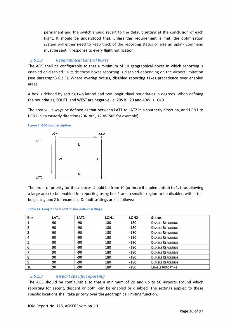
permanent and the switch should revert to the default setting at the conclusion of each
flight. It should be understood that, unless this requirement is met, the optimization
system will either need to keep track of the reporting status or else an uplink command
must be sent in response to every flight notification.
3.6.2.2 GeographicalControlboxesThe AOS shall be configurable so that a minimum of 10 geographical boxes in which reporting is
enabled or disabled. Outside these boxes reporting is disabled depending on the airport limitation
(see paragraph3.6.2.3). Where overlap occurs, disabled reporting takes precedence over enabled
areas.
A box is defined by setting two lateral and two longitudinal boundaries in degrees. When defining
the boundaries, SOUTH and WEST are negative i.e. 20S is –20 and 40W is –040
The area will always be defined as that between LAT1 to LAT2 in a southerly direction, and LON1 to
LON2 in an easterly direction (20N‐80S, 120W‐50E for example).
Figure 5: GEO box description
The order of priority for these boxes should be from 10 (or more if implemented) to 1, thus allowing
a large area to be enabled for reporting using box 1 and a smaller region to be disabled within this
box, using box 2 for example. Default settings are as follows:
Table 14: Geographical control box default settings
BOX LAT1 LAT2 LON1 LON2 STATUS
1 90 ‐90 180 ‐180 DISABLE REPORTING
2 90 ‐90 180 ‐180 DISABLE REPORTING
3 90 ‐90 180 ‐180 DISABLE REPORTING
4 90 ‐90 180 ‐180 DISABLE REPORTING
5 90 ‐90 180 ‐180 DISABLE REPORTING
6 90 ‐90 180 ‐180 DISABLE REPORTING
7 90 ‐90 180 ‐180 DISABLE REPORTING
8 90 ‐90 180 ‐180 DISABLE REPORTING
9 90 ‐90 180 ‐180 DISABLE REPORTING
10 90 ‐90 180 ‐180 ENABLE REPORTING
3.6.2.3 AirportspecificreportingThe AOS should be configurable so that a minimum of 20 and up to 50 airports around which
reporting for ascent, descent or both, can be enabled or disabled. The settings applied to these
specific locations shall take priority over the geographical limiting function.
IOM Report No. 115, AOSFRS version 1.1 Page 36 of 97

Each airport shall be described by its four letter ICAO airport designator. A flag is used to control
whether observing during ascent, descent or both is activated or deactivated for this location.
Following table shows the parameter configuration for the first airport. This is to be provided for the
number of airports able to be configured.
Table 15: Airport control parameters
CHARACTERS DATA DESCRIPTION REMARKS
4 IAIAIAIA ICAO AIRPORT DESIGNATOR “0000“ = DEFAULT
1 FA AIRPORT ACTIVATION FLAG 0 = ASCENT ON / DESCENT ON (DEFAULT) 1 = ASCENT ON / DESCENT OFF 2 = ASCENT OFF / DESCENT ON 3 = ASCENT OFF / DESCENT OFF
3.6.2.4 TimeLimitingIt should be possible to configure a single time window during which reporting is inhibited. This
setting has priority over all other settings except reporting off (see paragraph 3.6.2.1)
Table 16: Time limit control parameters
CHARACTERS DATA DESCRIPTION REMARKS
4 H1H1H2H2 DISABLE OBSERVATIONS BETWEEN SELECTED HOURS (00‐23) UTC, EVERY DAY
H1H1 = START OF INHIBIT PERIOD H2H2 = END OF INHIBIT PERIOD DEFAULT = 0000
The default value is interpreted as no interval selected and report though all 24 hour periods. The
Inhibit Period starts at the first designated hour in the day and ends when the next designated hour
is reached the same or next day. Thus 2301 means inhibit between 2300 hours and 0100 hours the
next day, every day. (Two hours spanning midnight UTC).
3.6.2.5 EDREventmessagesettingsIf EDR reporting is implemented, it should be possible to switch off EDR event reporting and alter the
settings for the threshold values as per the table below:
Table 17: EDR Event Message control parameters
CHARACTERS DATA DESCRIPTION REMARKS
1 0 OR 1 EDR EVENT MESSAGE DISABLED (0) OR ENABLED (1) 0 = DEFAULT
2 MM EDR TYPE 1 EVENT THRESHOLD DEFAULT = 0.18
2 MM EDR TYPE 2 EVENT THRESHOLD DEFAULT = 0.12
2 MM EDR TYPE 3 EVENT THRESHOLD DEFAULT = 0.06
3.6.3 ConfigurationMessageThe software should provide for a message that lists the current settings for all of the control
parameters mentioned in previous paragraph.
The message can be requested via either or both (in order of preference)
1. An uplink command.
2. Manual request through flight deck interface displays
IOM Report No. 115, AOSFRS version 1.1 Page 37 of 97

IOM Report No. 115, AOSFRS version 1.1 Page 38 of 97
For recommended contents and format of the Configuration Message, see Appendix B
3.6.4 AMDAROptimizationMessageAn AMDAR optimization message may be sent to the NMHS and/or airline prior to departure of
every flight. This message allows the NMHS and/or airline to alter the software configuration prior to
flight and thereby manage data volumes and eliminate redundant observations and messages.
For example, an ascent profile is required for an airport only once per hour. But if during that hour
more than one AMDAR equipped aircraft takes off, the system produces data that is not required. In
order to prevent multiple aircraft sending AMDAR messages, a ground based system determines
which aircraft to switch off by using the information in the optimization message.
The optimization message may be a standard OOOI message but should at least contain: ‐ Aircraft Identity ‐ Time Out (Parking brake released, all doors are closed.) ‐ DepartureAirport and ArrivalAirport ‐ Estimated time of departure from DepartureAirport ‐ Estimated time of arrival at DestinationAirport.
If implemented, the AMDAR Optimization Message production should be a configurable function of the AOS and, when activated, should be compiled and sent before Ascent at the earliest possible time after which the AOS has become active and the necessary parameters are available. A recommended format for the optimization message can be found in Appendix B.2
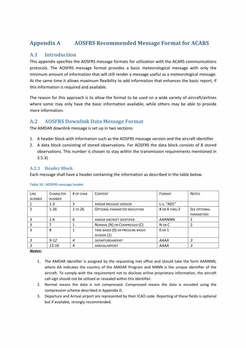
AppendixA AOSFRSRecommendedMessageFormatforACARS
A.1 IntroductionThis appendix specifies the AOSFRS message formats for utilization with the ACARS communications
protocols. The AOSFRS message format provides a basic meteorological message with only the
minimum amount of information that will still render a message useful as a meteorological message.
At the same time it allows maximum flexibility to add information that enhances the basic report, if
this information is required and available.
The reason for this approach is to allow the format to be used on a wide variety of aircraft/airlines
where some may only have the basic information available, while others may be able to provide
more information.
A.2 AOSFRSDownlinkDataMessageFormatThe AMDAR downlink message is set up in two sections:
1. A header block with information such as the AOSFRS message version and the aircraft identifier
2. A data block consisting of stored observations. For AOSFRS the data block consists of 8 stored
observations. This number is chosen to stay within the transmission requirements mentioned in
3.5.3)
A.2.1 HeaderBlockEach message shall have a header containing the information as described in the table below.
Table 18 : AOSFRS message header
LINE NUMBER
CHARACTER NUMBER
# OF CHAR CONTENT FORMAT NOTES
1 1‐3 3 AMDAR MESSAGE VERSION E.G. “A01”
2 1‐26 1 TO 26 OPTIONAL PARAMETER INDICATION # OR A THRU Z SEE OPTIONAL PARAMETERS
3 1‐6 6 AMDAR AIRCRAFT IDENTIFIER AANNNN 1
3 7 1 NORMAL (N) OR COMPRESSED (C) N OR C 2
3 8 1 TIME BASED (0) OR PRESSURE BASED SCHEME (1)
0 OR 1
3 9‐12 4 DEPARTUREAIRPORT AAAA 3
3 13‐16 4 ARRIVALAIRPORT AAAA 3
Notes:
1. The AMDAR identifier is assigned by the requesting met office and should take the form AANNNN,
where AA indicates the country of the AMDAR Program and NNNN is the unique identifier of the
aircraft. To comply with the requirement not to disclose airline proprietary information, the aircraft
call‐sign should not be utilized or revealed within this identifier.
2. Normal means the data is not compressed. Compressed means the data is encoded using the
compression scheme described in Appendix D.
3. Departure and Arrival airport are represented by their ICAO code. Reporting of these fields is optional
but if available, strongly recommended.
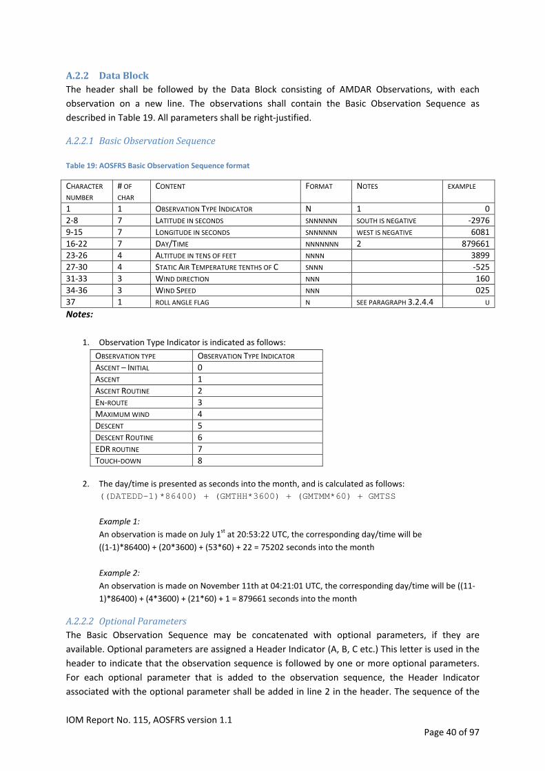
A.2.2 DataBlockThe header shall be followed by the Data Block consisting of AMDAR Observations, with each
observation on a new line. The observations shall contain the Basic Observation Sequence as
described in Table 19. All parameters shall be right‐justified.
A.2.2.1 BasicObservationSequence Table 19: AOSFRS Basic Observation Sequence format
# OF CHAR
CONTENT FORMAT NOTES EXAMPLE CHARACTER NUMBER
1 1 OBSERVATION TYPE INDICATOR N 1 0
2‐8 7 LATITUDE IN SECONDS SNNNNNN SOUTH IS NEGATIVE ‐2976
9‐15 7 LONGITUDE IN SECONDS SNNNNNN WEST IS NEGATIVE 6081
16‐22 7 DAY/TIME NNNNNNN 2 879661
23‐26 4 ALTITUDE IN TENS OF FEET NNNN 3899
27‐30 4 STATIC AIR TEMPERATURE TENTHS OF C SNNN ‐525
31‐33 3 WIND DIRECTION NNN 160
34‐36 3 WIND SPEED NNN 025
37 1 ROLL ANGLE FLAG N SEE PARAGRAPH 3.2.4.4 U
Notes:
1. Observation Type Indicator is indicated as follows:
OBSERVATION TYPE OBSERVATION TYPE INDICATOR
2. The day/time is presented as seconds into the month, and is calculated as follows:
((DATEDD-1)*86400) + (GMTHH*3600) + (GMTMM*60) + GMTSS
Example 1:
An observation is made on July 1st at 20:53:22 UTC, the corresponding day/time will be
((1‐1)*86400) + (20*3600) + (53*60) + 22 = 75202 seconds into the month
Example 2:
An observation is made on November 11th at 04:21:01 UTC, the corresponding day/time will be ((11‐
1)*86400) + (4*3600) + (21*60) + 1 = 879661 seconds into the month
ASCENT – INITIAL 0
ASCENT 1
ASCENT ROUTINE 2
EN‐ROUTE 3
MAXIMUM WIND 4
DESCENT 5
DESCENT ROUTINE 6
EDR ROUTINE 7
TOUCH‐DOWN 8
A.2.2.2 OptionalParametersThe Basic Observation Sequence may be concatenated with optional parameters, if they are
available. Optional parameters are assigned a Header Indicator (A, B, C etc.) This letter is used in the
header to indicate that the observation sequence is followed by one or more optional parameters.
For each optional parameter that is added to the observation sequence, the Header Indicator
associated with the optional parameter shall be added in line 2 in the header. The sequence of the
IOM Report No. 115, AOSFRS version 1.1 Page 40 of 97
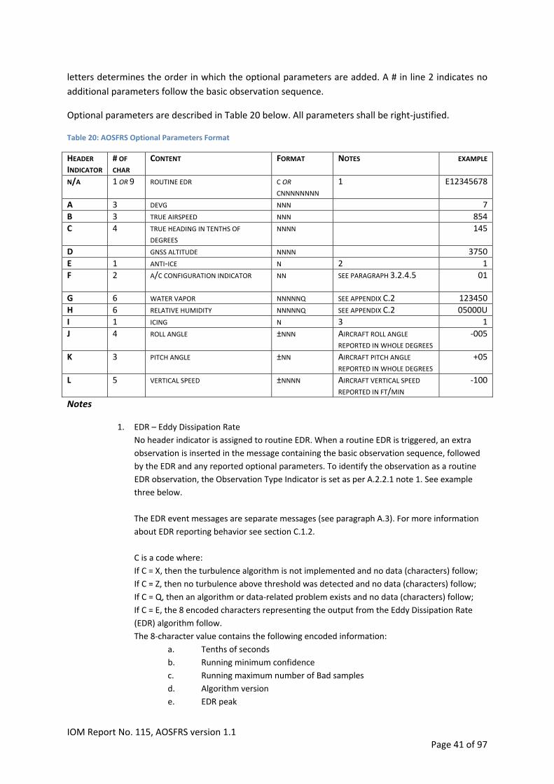
letters determines the order in which the optional parameters are added. A # in line 2 indicates no
additional parameters follow the basic observation sequence.
Optional parameters are described in Table 20 below. All parameters shall be right‐justified.
Table 20: AOSFRS Optional Parameters Format
# OF CHAR
CONTENT FORMAT NOTES EXAMPLE HEADER INDICATOR
N/A 1 OR 9 ROUTINE EDR C OR
CNNNNNNNN 1 E12345678
A 3 DEVG NNN 7
B 3 TRUE AIRSPEED NNN 854
C 4 TRUE HEADING IN TENTHS OF
DEGREES NNNN 145
D GNSS ALTITUDE NNNN 3750
E 1 ANTI‐ICE N 2 1
F 2 A/C CONFIGURATION INDICATOR NN SEE PARAGRAPH 3.2.4.5 01
G 6 WATER VAPOR NNNNNQ SEE APPENDIX C.2 123450
H 6 RELATIVE HUMIDITY NNNNNQ SEE APPENDIX C.2 05000U
I 1 ICING N 3 1
J 4 ROLL ANGLE ±NNN AIRCRAFT ROLL ANGLE REPORTED IN WHOLE DEGREES
‐005
K 3 PITCH ANGLE ±NN AIRCRAFT PITCH ANGLE REPORTED IN WHOLE DEGREES
+05
L 5 VERTICAL SPEED ±NNNN AIRCRAFT VERTICAL SPEED REPORTED IN FT/MIN
‐100
Notes
1. EDR – Eddy Dissipation Rate
No header indicator is assigned to routine EDR. When a routine EDR is triggered, an extra
observation is inserted in the message containing the basic observation sequence, followed
by the EDR and any reported optional parameters. To identify the observation as a routine
EDR observation, the Observation Type Indicator is set as per A.2.2.1 note 1. See example
three below.
The EDR event messages are separate messages (see paragraph A.3). For more information
about EDR reporting behavior see section C.1.2.
C is a code where:
If C = X, then the turbulence algorithm is not implemented and no data (characters) follow;
If C = Z, then no turbulence above threshold was detected and no data (characters) follow;
If C = Q, then an algorithm or data‐related problem exists and no data (characters) follow;
If C = E, the 8 encoded characters representing the output from the Eddy Dissipation Rate
(EDR) algorithm follow.
The 8‐character value contains the following encoded information:
a. Tenths of seconds
b. Running minimum confidence
c. Running maximum number of Bad samples
d. Algorithm version
e. EDR peak
IOM Report No. 115, AOSFRS version 1.1 Page 41 of 97

f. EDR mean
g. Peak EDR confidence
h. Mean EDR confidence
i. Peak location
j. Number of Good EDRs
2. Anti‐ice
Anti‐ice shall be reported using the following logic:
Heating of
Probes
(TAT-, Pitot-)
Engine inlets /
Propeller Blades
Wings leading edges
value of
Content
Anti-ice undetermined or invalid /
Anti-ice not activated no no no 0
Heating of probes only yes no no 1
Heating of probes and engine inlets yes yes no 3
Heating of probes, engine inlets and wings yes yes yes 7
Heating of engine inlets only* no yes no 2
Heating of wings only* no no yes 4
Heating of probes and wings* yes no yes 5
Heating of engine inlets and wings* no yes yes 6
* These anti‐ice heating configurations are usually not employed operationally.
3. Icing
Icing will be reported as value 1 when the aircraft icing sensor indicates no ice accretion, as
value 2 when the sensor indicates ice accretion is occurring, and as value 0 when the status
of icing is not able to be determined (note requires separate system installed, see note to
table 3 in Chapter 3).
Example 1 A message with only the basic observation sequence would look as follows:
A01 # AZ0001N1EHAMKJFK 0-2976 6081 8796613899-525160 25U 1-2976 6081 8796613899-525160 25U 1-2976 6081 8796613899-525160 25U 1-2976 6081 8796613899-525160 25U 1-2976 6081 8796613899-525160 25U 1-2976 6081 8796613899-525160 25U 1-2976 6081 8796613899-525160 25U 1-2976 6081 8796613899-525160 25U This indicates that the observations in the message are basic observations only, aircraft AZ0001 is
flying from Amsterdam to New York, the data is not compressed and the observations in ascent and
descent are based on the pressure scheme.
Example 2:
IOM Report No. 115, AOSFRS version 1.1 Page 42 of 97

GNSS and Anti‐ice are available and are added to the basic observation sequence. A message would
then look as follows
A01 DE AZ0001N1EHAMKJFK 1-2976 6081 8796613899-525160 25U38540 1-2976 6081 8796613899-525160 25U38540 1-2976 6081 8796613899-525160 25U38540 1-2976 6081 8796613899-525160 25U38540 1-2976 6081 8796613899-525160 25U38540 1-2976 6081 8796613899-525160 25U38540 1-2976 6081 8796613899-525160 25U38540 1-2976 6081 8796613899-525160 25U38540 This indicates that the observations in the message are basic observations amended with GNSS and
Anti‐ice information, aircraft AZ0001 is flying from Amsterdam to New York, the data is not
compressed and the observations in ascent and descent are based on the pressure scheme.
Example 3:
Water Vapor, True Airspeed, Anti‐ice, A/C config are available and added to the basic observation
sequence, in that order. EDR is also available. When a routine EDR is triggered, an extra observation
is inserted in the message containing the basic observation sequence plus any defined optional
parameters, amended with the routine EDR value. To identify the extra observation as a routine EDR
observation the Observation Type Indicator for that observation is set to ‘B’.
A message would look like:
A01 GBEF NL0032N0WMKKYMML 1-2976 6081 8796613899-525160 25U123450854101 7-2976 6081 8796613899-525160 25U123450854101E123456781)
1-2976 6081 8796613899-525160 25U123450854101 1-2976 6081 8796613899-525160 25U123450854101 3-2976 6081 8796613899-525160 25U123450854101 7-2976 6081 8796613899-525160 25U123450854101E123456781)
3-2976 6081 8796613899-525160 25U123450854101 3-2976 6081 8796613899-525160 25U123450854101 1) Routine EDR observation This indicates that the observations in the message are basic observations amended with Water
Vapor, True Airspeed, Anti‐ice, A/C configuration, aircraft NL0032 is flying from Kuala Lumpur to
Melbourne, the data is not compressed and the observations in ascent and descent are based on the
time based scheme.
The data is interspersed with routine EDR observations, indicated by ‘7’ in the Observation Type
Indicator field.
IOM Report No. 115, AOSFRS version 1.1 Page 43 of 97
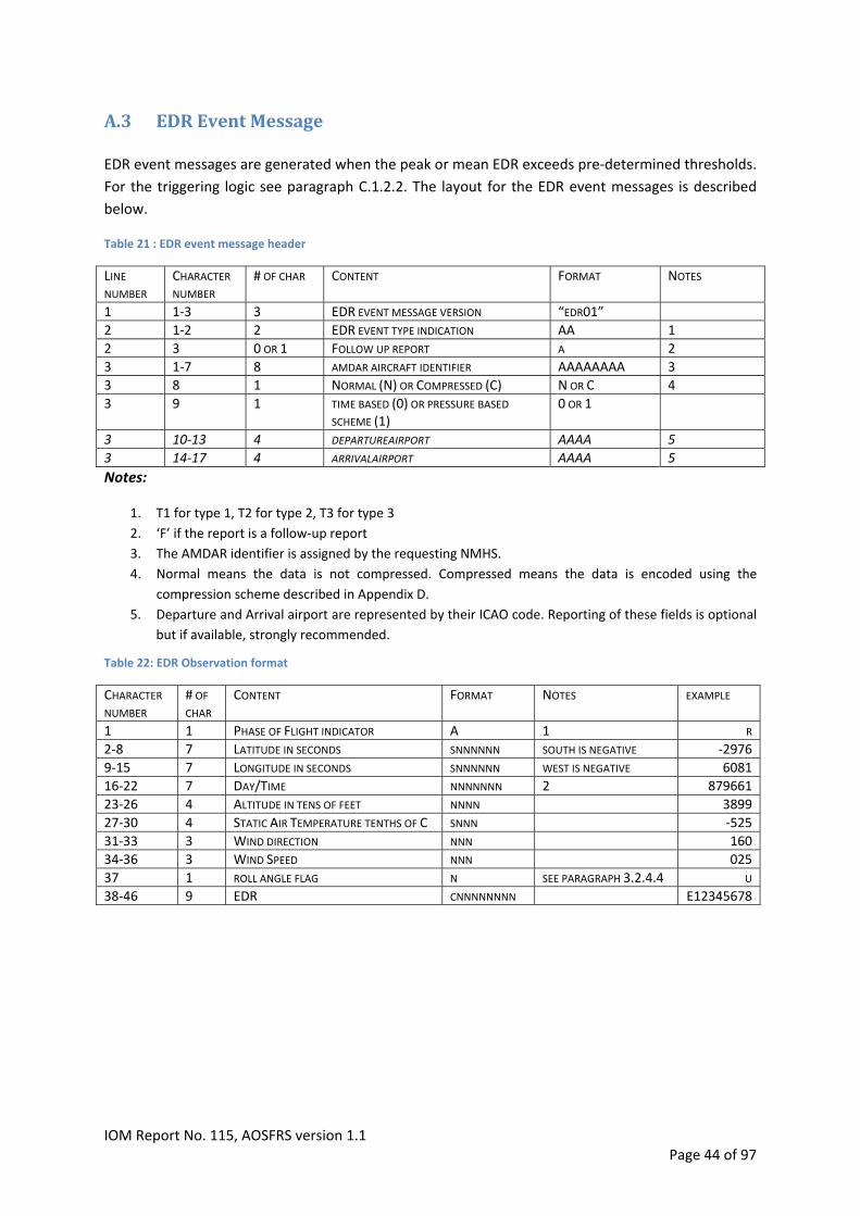
A.3 EDREventMessage EDR event messages are generated when the peak or mean EDR exceeds pre‐determined thresholds.
For the triggering logic see paragraph C.1.2.2. The layout for the EDR event messages is described
below.
Table 21 : EDR event message header
CHARACTER NUMBER
# OF CHAR CONTENT FORMAT NOTES LINE NUMBER
1 1‐3 3 EDR EVENT MESSAGE VERSION “EDR01”
2 1‐2 2 EDR EVENT TYPE INDICATION AA 1
2 3 0 OR 1 FOLLOW UP REPORT A 2
3 1‐7 8 AMDAR AIRCRAFT IDENTIFIER AAAAAAAA 3
3 8 1 NORMAL (N) OR COMPRESSED (C) N OR C 4
9 1 TIME BASED (0) OR PRESSURE BASED SCHEME (1)
0 OR 1 3
3 10‐13 4 DEPARTUREAIRPORT AAAA 5
3 14‐17 4 ARRIVALAIRPORT AAAA 5
Notes:
1. T1 for type 1, T2 for type 2, T3 for type 3
2. ‘F’ if the report is a follow‐up report
3. The AMDAR identifier is assigned by the requesting NMHS.
4. Normal means the data is not compressed. Compressed means the data is encoded using the
compression scheme described in Appendix D.
5. Departure and Arrival airport are represented by their ICAO code. Reporting of these fields is optional
but if available, strongly recommended.
Table 22: EDR Observation format
# OF CHAR
CONTENT FORMAT NOTES EXAMPLE CHARACTER NUMBER
1 1 PHASE OF FLIGHT INDICATOR A 1 R
2‐8 7 LATITUDE IN SECONDS SNNNNNN SOUTH IS NEGATIVE ‐2976
9‐15 7 LONGITUDE IN SECONDS SNNNNNN WEST IS NEGATIVE 6081
16‐22 7 DAY/TIME NNNNNNN 2 879661
23‐26 4 ALTITUDE IN TENS OF FEET NNNN 3899
27‐30 4 STATIC AIR TEMPERATURE TENTHS OF C SNNN ‐525
31‐33 3 WIND DIRECTION NNN 160
34‐36 3 WIND SPEED NNN 025
37 1 ROLL ANGLE FLAG N SEE PARAGRAPH 3.2.4.4 U
38‐46 9 EDR CNNNNNNNN E12345678
IOM Report No. 115, AOSFRS version 1.1 Page 44 of 97

1. Observation Type Indicator is indicated as follows:
OBSERVATION TYPE OBSERVATION TYPE INDICATOR
ASCENT – INITIAL 0
ASCENT 1
ASCENT ROUTINE 2
EN‐ROUTE 3
MAXIMUM WIND 4
DESCENT 5
DESCENT ROUTINE 6
EDR ROUTINE 7
TOUCH‐DOWN 8
2. The day/time is presented as seconds into the month, and is calculated as follows:
((DATEDD-1)*86400) + (GMTHH*3600) + (GMTMM*60) + GMTSS
Example 1:
An observation is made on July 1st at 20:53:22 UTC, the corresponding day/time will be
((1‐1)*86400) + (20*3600) + (53*60) + 22 = 75202 seconds into the month
Example 2:
An observation is made on November 11th at 04:21:01 UTC, the corresponding day/time will be ((11‐
1)*86400) + (4*3600) + (21*60) + 1 = 879661 seconds into the month
Examples:
1) Type 1 event, 3 EDR measurements in buffer, follow‐up report
EDR01 T1 AZ0001N1EHAMKJFK 1-2976 6081 8796613899-525160 25UE12345678 1-2976 6081 8796613899-525160 25UE12345678 1-2976 6081 8796613899-525160 25UE12345678 EDR01 T1F AZ0001N1EHAMKJFK 1-2976 6081 8796613899-525160 25UE12345678 1-2976 6081 8796613899-525160 25UE12345678 1-2976 6081 8796613899-525160 25UE12345678 1-2976 6081 8796613899-525160 25UE12345678 1-2976 6081 8796613899-525160 25UE12345678 1-2976 6081 8796613899-525160 25UE12345678
2) Type 3event, no follow up report
IOM Report No. 115, AOSFRS version 1.1 Page 45 of 97

EDR01 T3 AZ0001N1EHAMKJFK 1-2976 6081 8796613899-525160 25UE12345678 1-2976 6081 8796613899-525160 25UE12345678 1-2976 6081 8796613899-525160 25UE12345678 1-2976 6081 8796613899-525160 25UE12345678 1-2976 6081 8796613899-525160 25UE12345678 1-2976 6081 8796613899-525160 25UE12345678
IOM Report No. 115, AOSFRS version 1.1 Page 46 of 97
A.4 AOSFRSConfigurationFunctionalityandUplinkControlThe following section describes the recommended functionality to enable the configurability of
AMDAR onboard software (AOS) and its update through ACARS uplink as specified within section 3.6.
The AOS configuration functions are divided into a set of basic and extended parameters that allow
the full functionality specified in 3.6 to be defined. This structure of basic and extended parameters
then provides a convenient means to define an uplink control format to modify the configuration
parameters as required. This same structure is also used to define the format for a configuration
status report as defined in section A.5.
When uplinked and passed to the AOS application, the parameter values either act to change the
default (permanent) configuration of the AOS or else initiate a one‐off function call (e.g. generation
of a downlink status report).
A.4.1 BasicConfigurationThe column “Content” of Table A.4‐1 provides the data for the uplink command string which, upon
reception by the ACARS system, is passed to the onboard AOS application for processing to affect
alteration of the onboard configuration of the application. The size of the message is dependent
upon the number and type of changes made to the configuration but will consist of a message
header indicator (e.g. AOS06, indicating the AOS version) followed by a 16 character string as a
minimum. For example, a Status Report request with no other configuration changes requested
might consist of 21 characters only – AOS06190999999999999/.
In most instances, the 9 digit is used to indicate when no change to a particular configuration is
required. When a change is required, the Data will indicate either the change to be made or that the
configuration change is indicated by the extended command string following the Data and as defined
in the referenced table. The Default Values in the tables define the recommended default
configuration of the AOS. These values are changed by the uplink command message as necessary
and become permanent (i.e. are restored upon system initialization and/or reset) unless otherwise
indicated.
The Reporting OFF setting takes priority over all other configuration settings. The Airport Reporting
and Activation of Reporting in Defined Geographical Boxes configurations take priority over Report
Activation settings 1‐7 only. The Airport Reporting takes priority over the Activation of Reporting in
Defined Geographical Boxes. The Inhibit Reporting Between Selected Hours configuration takes
priority over all other configurations except the Reporting OFF configuration.
IOM Report No. 115, AOSFRS version 1.1 Page 47 of 97
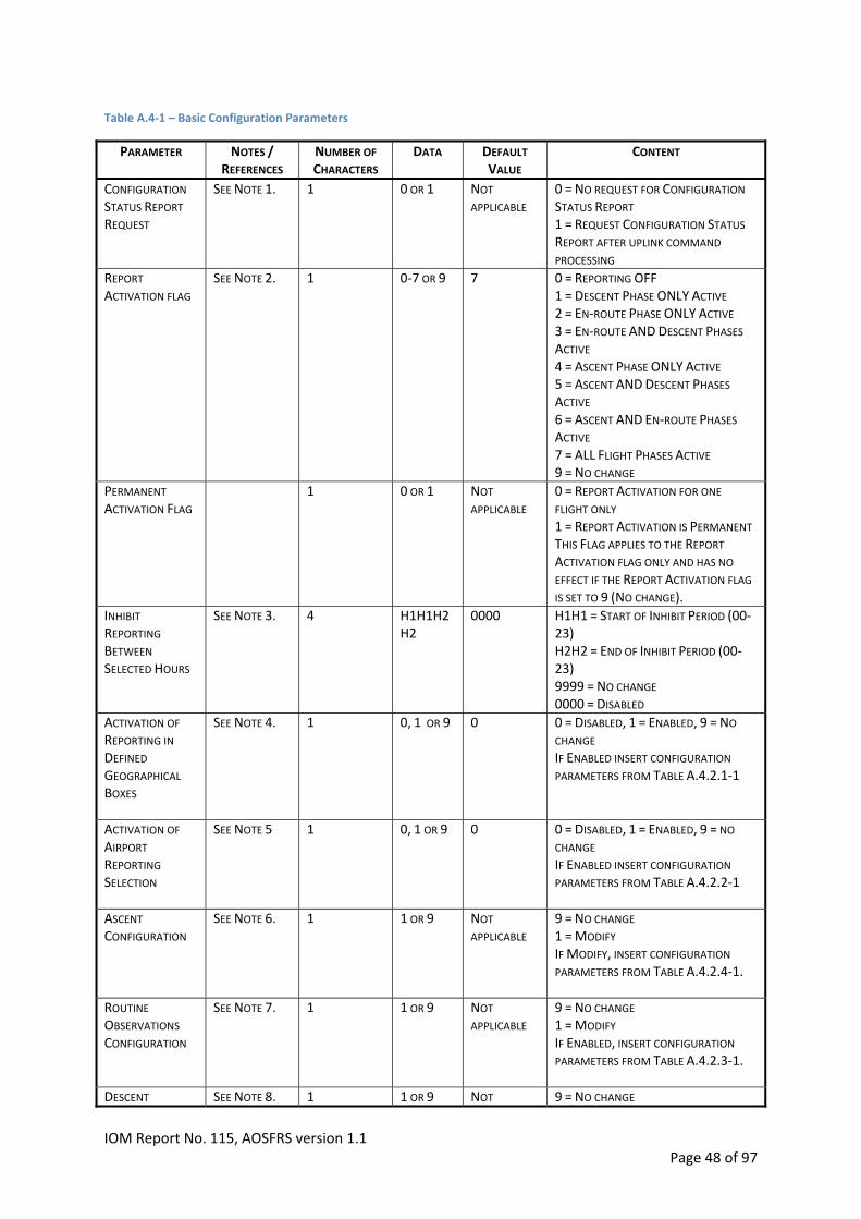
Table A.4‐1 – Basic Configuration Parameters
NOTES / REFERENCES
NUMBER OF
CHARACTERS DATA DEFAULT
VALUE CONTENT PARAMETER
CONFIGURATION STATUS REPORT REQUEST
SEE NOTE 1. 1 0 OR 1 NOT
APPLICABLE 0 = NO REQUEST FOR CONFIGURATION STATUS REPORT 1 = REQUEST CONFIGURATION STATUS REPORT AFTER UPLINK COMMAND
PROCESSING
REPORT ACTIVATION FLAG
SEE NOTE 2. 1 0‐7 OR 9 7 0 = REPORTING OFF 1 = DESCENT PHASE ONLY ACTIVE 2 = EN‐ROUTE PHASE ONLY ACTIVE 3 = EN‐ROUTE AND DESCENT PHASES ACTIVE 4 = ASCENT PHASE ONLY ACTIVE 5 = ASCENT AND DESCENT PHASES ACTIVE 6 = ASCENT AND EN‐ROUTE PHASES ACTIVE 7 = ALL FLIGHT PHASES ACTIVE 9 = NO CHANGE
1 0 OR 1 NOT
APPLICABLE 0 = REPORT ACTIVATION FOR ONE FLIGHT ONLY 1 = REPORT ACTIVATION IS PERMANENT THIS FLAG APPLIES TO THE REPORT ACTIVATION FLAG ONLY AND HAS NO EFFECT IF THE REPORT ACTIVATION FLAG IS SET TO 9 (NO CHANGE).
PERMANENT
ACTIVATION FLAG
SEE NOTE 3. 4 H1H1H2H2
0000 H1H1 = START OF INHIBIT PERIOD (00‐23) H2H2 = END OF INHIBIT PERIOD (00‐23) 9999 = NO CHANGE 0000 = DISABLED
INHIBIT REPORTING BETWEEN
SELECTED HOURS
ACTIVATION OF REPORTING IN DEFINED GEOGRAPHICAL BOXES
SEE NOTE 4. 1 0, 1 OR 9 0 0 = DISABLED, 1 = ENABLED, 9 = NO
CHANGE IF ENABLED INSERT CONFIGURATION PARAMETERS FROM TABLE A.4.2.1‐1
ACTIVATION OF AIRPORT REPORTING SELECTION
SEE NOTE 5 1 0, 1 OR 9 0 0 = DISABLED, 1 = ENABLED, 9 = NO CHANGE IF ENABLED INSERT CONFIGURATION PARAMETERS FROM TABLE A.4.2.2‐1
ASCENT CONFIGURATION
SEE NOTE 6.
1 1 OR 9 NOT
APPLICABLE 9 = NO CHANGE 1 = MODIFY IF MODIFY, INSERT CONFIGURATION PARAMETERS FROM TABLE A.4.2.4‐1.
ROUTINE OBSERVATIONS
CONFIGURATION
SEE NOTE 7.
1 1 OR 9 NOT
APPLICABLE 9 = NO CHANGE 1 = MODIFY IF ENABLED, INSERT CONFIGURATION PARAMETERS FROM TABLE A.4.2.3‐1.
DESCENT SEE NOTE 8. 1 1 OR 9 NOT 9 = NO CHANGE
IOM Report No. 115, AOSFRS version 1.1 Page 48 of 97
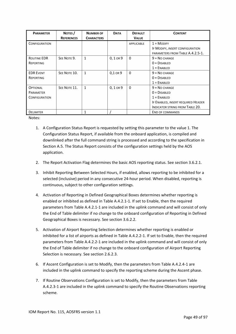
NOTES / REFERENCES
NUMBER OF
CHARACTERS DATA DEFAULT
VALUE CONTENT PARAMETER
CONFIGURATION
APPLICABLE 1 = MODIFY IF MODIFY, INSERT CONFIGURATION PARAMETERS FROM TABLE A.4.2.5‐1.
ROUTINE EDR REPORTING
SEE NOTE 9. 1 0, 1 OR 9 0 9 = NO CHANGE 0 = DISABLED 1 = ENABLED
EDR EVENT REPORTING
SEE NOTE 10. 1 0,1 OR 9 0 9 = NO CHANGE 0 = DISABLED 1 = ENABLED
OPTIONAL
PARAMETER
CONFIGURATION
SEE NOTE 11. 1 0, 1 OR 9 0 9 = NO CHANGE 0 = DISABLED 1 = ENABLED IF ENABLED, INSERT REQUIRED HEADER INDICATOR STRING FROM TABLE 20.
DELIMITER 1 / END OF COMMANDS
Notes:
1. A Configuration Status Report is requested by setting this parameter to the value 1. The
Configuration Status Report, if available from the onboard application, is compiled and
downlinked after the full command string is processed and according to the specification in
Section A.5. The Status Report consists of the configuration settings held by the AOS
application.
2. The Report Activation Flag determines the basic AOS reporting status. See section 3.6.2.1.
3. Inhibit Reporting Between Selected Hours, if enabled, allows reporting to be inhibited for a
selected (inclusive) period in any consecutive 24‐hour period. When disabled, reporting is
continuous, subject to other configuration settings.
4. Activation of Reporting in Defined Geographical Boxes determines whether reporting is
enabled or inhibited as defined in Table A.4.2.1‐1. If set to Enable, then the required
parameters from Table A.4.2.1‐1 are included in the uplink command and will consist of only
the End of Table delimiter if no change to the onboard configuration of Reporting in Defined
Geographical Boxes is necessary. See section 3.6.2.2.
5. Activation of Airport Reporting Selection determines whether reporting is enabled or
inhibited for a list of airports as defined in Table A.4.2.2‐1. If set to Enable, then the required
parameters from Table A.4.2.2‐1 are included in the uplink command and will consist of only
the End of Table delimiter if no change to the onboard configuration of Airport Reporting
Selection is necessary. See section 2.6.2.3.
6. If Ascent Configuration is set to Modify, then the parameters from Table A.4.2.4‐1 are
included in the uplink command to specify the reporting scheme during the Ascent phase.
7. If Routine Observations Configuration is set to Modify, then the parameters from Table
A.4.2.3‐1 are included in the uplink command to specify the Routine Observations reporting
scheme.
IOM Report No. 115, AOSFRS version 1.1 Page 49 of 97

8. If Descent Configuration is set to Modify, then the parameters from Table A.4.2.5‐1 are
included in the uplink command to specify the reporting scheme during the Descent phase.
9. If Routine EDR Reporting is Enabled, then the reporting of Routine Eddy Dissipation Rate
(EDR) is activated according to the provisions made in section A.2. If the onboard application
is unable to report Routine EDR Content will be padded with the solidus character (/).
10. If EDR Event Reporting is Enabled and this function is available to the Meteorological Report
application, then the reporting of turbulence EDR Event‐triggered reporting is activated
according to the provisions made in Section A.3.
11. If Optional Parameter Configuration is Enabled, then the optional parameters required to be
reported in the AOS are configured by inserting the appropriate string according to the
Header Indicator in Table 20. When the Optional Parameter Configuration has been Enabled,
the Optional Parameter Indication in the Data Header in Table 18 is altered accordingly. If
the onboard application is unable to report the requested Optional Parameter, then the
Content will be padded with the solidus character (/).
A.4.2 ExtendedConfiguration
A.4.2.1 GeographicalControlBoxesThis table defines uplink configuration parameters for reporting in configurable geographical areas
(section 3.6.2.2) when the Activation of Reporting in Defined Geographical Boxes (Table A.4‐1), is
enabled. It allows up to NMNM latitude/longitude boxes that define regions in which profile and
enroute observations are either Reported or Inhibited. When Enabled, reporting is made according
to the defined geographical boxes. When Disabled, reporting is made according to the Report
Activation flag and other configuration settings. If no change is required to the existing onboard
configuration of geographical control boxes then the command string will consist of only the End of
Table Delimiter (/).
Table A.4.2.1‐1 – Geographical Control Boxes Parameters
NOTES / REFERENCES
NUMBER OF
CHARACTERS DATA CONTENT PARAMETER
2 NRNR NRNR = 00 ‐ NMNM (WHERE NMNM
IS THE MAXIMUM CONFIGURABLE
GEOGRAPHICAL BOXES). DEFAULT = 00
NUMBER BOXES
FOLLOWING
14 L1L1 A1L2L2A2
L3 L3L3 B1L4L4 L4B2 LAT IN DEGREES NORTH (A = N) OR SOUTH (A = S) LON IN DEGREES EAST (B = E) OR WEST (B = W) CONVENTION IS L1L1 TO L2L2 (N ‐S) AND L3L3L3 TO L4L4L4 (W‐E).
LAT/LONG BOX
1 0 OR 1 0 = INHIBITED. 1 = REPORTED. REPORTED HAS PRIORITY OVER INHIBITED.
REPORTED OR INHIBITED
AS ABOVE REPEAT ABOVE TWO ROWS
NRNR‐1 TIMES
(NRNR – 1) * 15 AS ABOVE
IOM Report No. 115, AOSFRS version 1.1 Page 50 of 97

DELIMITER 1 / END OF DATA.
A.4.2.2 AirportConfigurationParametersThis table defines uplink configuration parameters for reporting on ascent or descent when
Activation of Airport Reporting Selection (Table A.4‐1), is enabled. It allows up to NMNM Airports to
be configured for reporting according to the Airport Activation Flag. If no change is required to the
existing onboard configuration of Airport Configuration then the command string will consist of only
the End of Table Delimiter (/).
Table A.4.2.2‐1 – Airport Configuration Parameters
NOTES / REFERENCES
NUMBER OF
CHARACTERS DATA CONTENT PARAMETER
2
NANA NANA = 00 ‐ NMNM ( WHERE
NMNM IS THE MAXIMUM
CONFIGURABLE AIRPORTS). DEFAULT = 00
NUMBER OF AIRPORTS FOLLOWING
4 AAAA ICAO AIRPORT DESIGNATOR
1 0 ‐ 3 0 = ASCENT ON / DESCENT ON
(DEFAULT) 1 = ASCENT ON / DESCENT OFF 2 = ASCENT OFF / DESCENT ON 3 = ASCENT OFF/ DESCENT OFF
AIRPORT ACTIVATION FLAG
AS ABOVE REPEAT ABOVE TWO
ROWS NRNR‐1 TIMES
(NRNR‐1) * 5 AS ABOVE
DELIMITER 1 / END OF DATA
A.4.2.3 RoutineObservationsandWindReportingStatusThis table defines uplink settings for Routine Observations reporting configuration and interval of
reporting. It also enables or disables reporting of the maximum wind observation (section 3.3.4)
during the enroute flight phase (only). These configurations are relevant only when the
corresponding phase of flight is Active based on the Report Activation configuration in Table A.4‐1.
Table A.4.2.3‐1 – Routine Observations and Wind Reporting Status
PARAMETER NOTES / REFERENCES NUMBER OF CHARACTERS DATA CONTENT
1 1, 2, 9 9 = NO CHANGE 1 = ROUTINE OBSERVATIONS
DURING ENROUTE PHASE ONLY
(DEFAULT) 2 = ROUTINE OBSERVATIONS
DURING ALL PHASES
ROUTINE REPORTING CONFIGURATION
2 MM 99 = NO CHANGE DEFAULT = 07 RANGE = 01 – 60
ROUTINE OBSERVATIONS
INTERVAL (MINUTES)
ENABLE OR DISABLE MAXIMUM WIND
REPORTING
1 0 OR 1 9 = NO CHANGE DEFAULT = 1 (ENABLE) DISABLE = 0
DELIMITER 1 / END OF DATA
IOM Report No. 115, AOSFRS version 1.1 Page 51 of 97

A.4.2.4 AscentConfigurationParametersThis table is used to configure reporting during the Ascent phase. It is uplinked when the Ascent
Configuration flag is set to Modify (See Tables A.4‐1).
When the Pressure Based Scheme is active, the Routine Observations Interval (parameter 2 of Table
A.4.2.3.‐1) is used during the Ascent phase to ensure that observations are still made if there is a
pause in the Ascent phase. This function is not active if Ascent selection is disabled in Table A.4‐1.
Table A.4.2.4‐1 – Ascent Configuration Parameters
NOTES / REFERENCES
NUMBER OF
CHARACTERS DATA CONTENT PARAMETER
SEE NOTE 1
1 0 OR 1 0 = PRESSURE BASED SCHEME 1 = TIME BASED SCHEME DEFAULT = 0
ASCENT REPORTING SCHEME
2 SS TIME BASED SCHEME DEFAULT = 06 RANGE = 03 – 20
ASCENT PART 1 TIME
INTERVAL (SECONDS)
ASCENT PART 1 DURATION
(SECONDS)
3 SSS TIME BASED SCHEME DEFAULT = 090 RANGE = 030– 200
ASCENT PART 2 TIME
INTERVALS
(SECONDS)
2 SS TIME BASED SCHEME DEFAULT = 20 RANGE = 20 – 60
ASCENT TOTAL DURATION (SECONDS X 10)
3 SSS TIME BASED SCHEME DEFAULT = 051 RANGE = 051 – 111 SEE NOTE 2
ASCENT PART 1 PRESSURE INTERVALS
(HPA)
2 NN PRESSURE BASED SCHEME DEFAULT = 10 RANGE = 1‐20
2 NN PRESSURE BASED SCHEME VALUE = 10 OR 20 DEFAULT = 10 NOTE: ASCENT PART 1 PRESSURE INTERVAL X ASCENT PART 1 NUMBER OF OBSERVATIONS
MUST BE 100.
NUMBER OF
OBSERVATIONS MADE
DURING ASCENT PART 1
ASCENT PART 2 PRESSURE INTERVALS
(HPA)
2 NN PRESSURE BASED SCHEME DEFAULT = 50 RANGE = 20‐50
SEE NOTE 2 3 HHH DEFAULT = 200 RANGE = 150 – 350
TOP OF CLIMB
(X100FT)
DELIMITER 1 / END OF DATA
Notes:
1. The first field indicates whether the Time or Pressure Based Scheme is selected for the
ascent phase. The next 4 fields give the required parameters for the Time Based Scheme.
Fields 6 to 8 give the required parameters to define the Pressure Based Scheme. For a full
description of the flight phases and reporting schemes, see section 3.4.
2. The Ascent phase is deemed to be complete and En‐route phase commenced when either
the Top of Climb has been reached or the Ascent Total Duration has elapsed.
IOM Report No. 115, AOSFRS version 1.1 Page 52 of 97

A.4.2.5 DescentConfigurationParametersThis table is used to configure reporting during the Descent phase. It is uplinked when the Modify
Descent Configuration parameter is set to Modify (See Tables A.4‐1.).
When the Pressure Based Scheme is active, the Routine Observations Interval (parameter 2 of Table
A.4.3.2‐1) is used during the Descent phase to ensure that observations are still made if there is a
pause in the Descent phase. This function is not active if Descent selection is disabled in Table A.4‐1.
Table A.4.2.5‐1 – Descent Configuration Parameters
NOTES / REFERENCES
NUMBER OF
CHARACTERS DATA CONTENT PARAMETER
DESCENT REPORTING SCHEME
1 0 OR 1 0 = PRESSURE BASED SCHEME 1 = TIME BASED SCHEME DEFAULT = 0
3 SSS TIME BASED SCHEME DEFAULT = 040 RANGE = 010 – 300
DESCENT PART 1 AND 2 TIME
INTERVAL
(SECONDS)
DESCENT PART 1 PRESSURE
INTERVAL (HPA)
2 NN PRESSURE BASED SCHEME VALUE = 25 OR 50 DEFAULT = 50 (FROM TOP OF DESCENT TO FINAL 100HPA)
DESCENT PART 2 PRESSURE
INTERVAL (HPA)
2 NN PRESSURE BASED SCHEME VALUE = 05 OR 10 DEFAULT = 10 (FOR THE FINAL 100HPA)
3 HHH DEFAULT = 200 RANGE = 150 – 350 SEE NOTE 2
TOP OF DESCENT (X 100FT)
DELIMITER 1 / END OF DATA
Notes:
1. The first field indicates whether the Time or Pressure Based Scheme is selected for the
descent phase. The next field gives the required time interval for the Time Based Scheme.
Parameter 3 gives the required interval for the Pressure Based Scheme.
2. The Descent phase is deemed to have commenced when the pressure altitude falls below
the Top of Descent
A.4.3 ExampleCommandUplinksExample 1
Configuration change: The following uplink command initiates the following changes in the onboard
configuration of the Meteorological Report application:
1. Sets Report Activation flag to ALL Phases Active for one flight only; and,
2. Makes a Configuration Status Report Request.
Command uplink: AOS01170999999999999/
Example 2
IOM Report No. 115, AOSFRS version 1.1 Page 53 of 97

Configuration change: The following uplink command initiates the following changes in the onboard
configuration of the Meteorological Report application:
1. Configures to Inhibit Reporting Between Selected Hours 00 and 04 UTC inclusive (command
segment: 10004); and,
2. Enables Activation of Reporting in Defined Geographical Boxes (command segment:
10210S70S150E100E130S40S130E140E0/): Two boxes defined by geographical coordinates;
first box (10S,150E) to (70S, 100E) is to be Reported; second box (30S, 130E) to (40S, 140E) is
Inhibited for reporting.
Command uplink: AOS01091000410210S70S150E100E130S40S130E140E0/9999999/
Example 3
Configuration change: The following uplink command initiates the following changes in the onboard
configuration of the Meteorological Report application:
1. Enables Activation of Airport Reporting Selection (command segment:
104EHYY0LFPG0VHHH1YSSY1/): Four airports are configured for reporting (EHYY and LFPG
with Ascent and Descent ON and VHHH and YSSY with Ascent ON and Descent OFF); and,
2. The Ascent Configuration is modified to report with the following configuration (command
segment: 100609020051052030200): Pressure based scheme is used; Ascent Part 1 time
interval = 6 seconds; Ascent Part 1 duration = 90 seconds; Ascent Part 2 time interval = 20
seconds; Ascent Total Duration = 510 seconds; Ascent Part 1 pressure interval = 5 hPa;
Number of observations made during Ascent Part 1 = 20; Ascent Part 2 pressure intervals =
30 hPa; Top of Climb = 200 hPa.
Command uplink: AOS0109199999104EHYY0LFPG0VHHH1YSSY1/100609020051052030200/99999/
Example 4
1. Configuration change: The following uplink command initiates the following changes in the
onboard configuration of the Meteorological Report application:
2. The Routine Observations Configuration is modified (command segment: 11990/) to: set the
Routine Reporting Configuration to Routine Observations during all phases, and the
Maximum Wind Reporting is disabled.
Command uplink: AOS01091999999911990/9999/
Example 5
Configuration change: The following uplink command initiates the following changes in the onboard
configuration of the Meteorological Report application:
1. The Optional Parameter Configuration is modified (command segment: 1BCG/) to: enable
the reporting of True Airspeed, True Heading and Water Vapor.
IOM Report No. 115, AOSFRS version 1.1 Page 54 of 97

Command uplink: AOS01091999999999991BCG/
IOM Report No. 115, AOSFRS version 1.1 Page 55 of 97

A.5 AOSFRSConfigurationStatusMessageThe following specification of the Configuration Status Report defines the content and format of a
downlink message that provides the current configuration status of the onboard AOS application.
The report is produced in response to the uplink command request that is defined in section A.4.
The Configuration Status Report will have the following format, preceded by an appropriate message
identification header, e.g. AOS01.
Table A.5‐1 – Configuration Status
DATA DESCRIPTION CONTENT NUMBER OF
CHARACTERS
0‐7 REPORT ACTIVATION FLAG
0 = REPORTING OFF 1 = DESCENT PHASE ONLY ACTIVE 2 = EN‐ROUTE PHASE ONLY ACTIVE 3 = EN‐ROUTE AND DESCENT PHASES ACTIVE 4 = ASCENT PHASE ONLY ACTIVE 5 = ASCENT AND DESCENT PHASES ACTIVE 6 = ASCENT AND EN‐ROUTE PHASES ACTIVE 7 = ALL FLIGHT PHASES ACTIVE
1
H1H1H2H2 INHIBIT REPORTING BETWEEN SELECTED HOURS (00‐23) UTC, EVERY DAY.
H1H1 = START OF INHIBIT PERIOD (00‐23) H2H2 = END OF INHIBIT PERIOD (00‐23) 0000 = DISABLED
4
1 AND CONTENT OF CONFIGURATION
TABLE
0 OR 1 AND CONTENT OF CONFIGURATION
TABLE
ACTIVATION OF REPORTING IN DEFINED GEOGRAPHICAL BOXES
0 = DISABLED, 1 = ENABLED INSERT CONFIGURATION STATUS FROM TABLE A.4.2.1‐1
1 AND CONTENT OF CONFIGURATION
TABLE
0 OR 1 AND CONTENT OF CONFIGURATION
TABLE
ACTIVATION OF AIRPORT REPORTING SELECTION
0 = DISABLED, 1 = ENABLED INSERT CONFIGURATION STATUS FROM TABLE A.4.2.2‐1
CONTENT OF CONFIGURATION
TABLE
ASCENT CONFIGURATION
INSERT CONFIGURATION STATUS FROM TABLE A.4.2.4‐1.
CONTENT OF CONFIGURATION
TABLE
CONTENT OF CONFIGURATION
TABLE
CONTENT OF CONFIGURATION
TABLE
ROUTINE OBSERVATIONS
CONFIGURATION
INSERT CONFIGURATION STATUS FROM TABLE A.4.2.3‐1.
CONTENT OF CONFIGURATION
TABLE
DESCENT CONFIGURATION
INSERT CONFIGURATION STATUS FROM TABLE A.4.2.5‐1. CONTENT OF CONFIGURATION
TABLE
0, OR 1 ROUTINE EDR REPORTING
0 = DISABLED 1 = ENABLED
1
0, OR 1 EDR EVENT REPORTING
0 = DISABLED 1 = ENABLED
1
1 AND OPTIONAL
PARAMETER
INDICATION IN TABLE 5.3.13.6‐2
0 OR 1 AND OPTIONAL
PARAMETER
INDICATION IN TABLE 5.3.13.6‐2
OPTIONAL
PARAMETER
CONFIGURATION
0 = DISABLED 1 = ENABLED
1 / DELIMITER END OF CONFIGURATION STATUS
IOM Report No. 115, AOSFRS version 1.1 Page 56 of 97
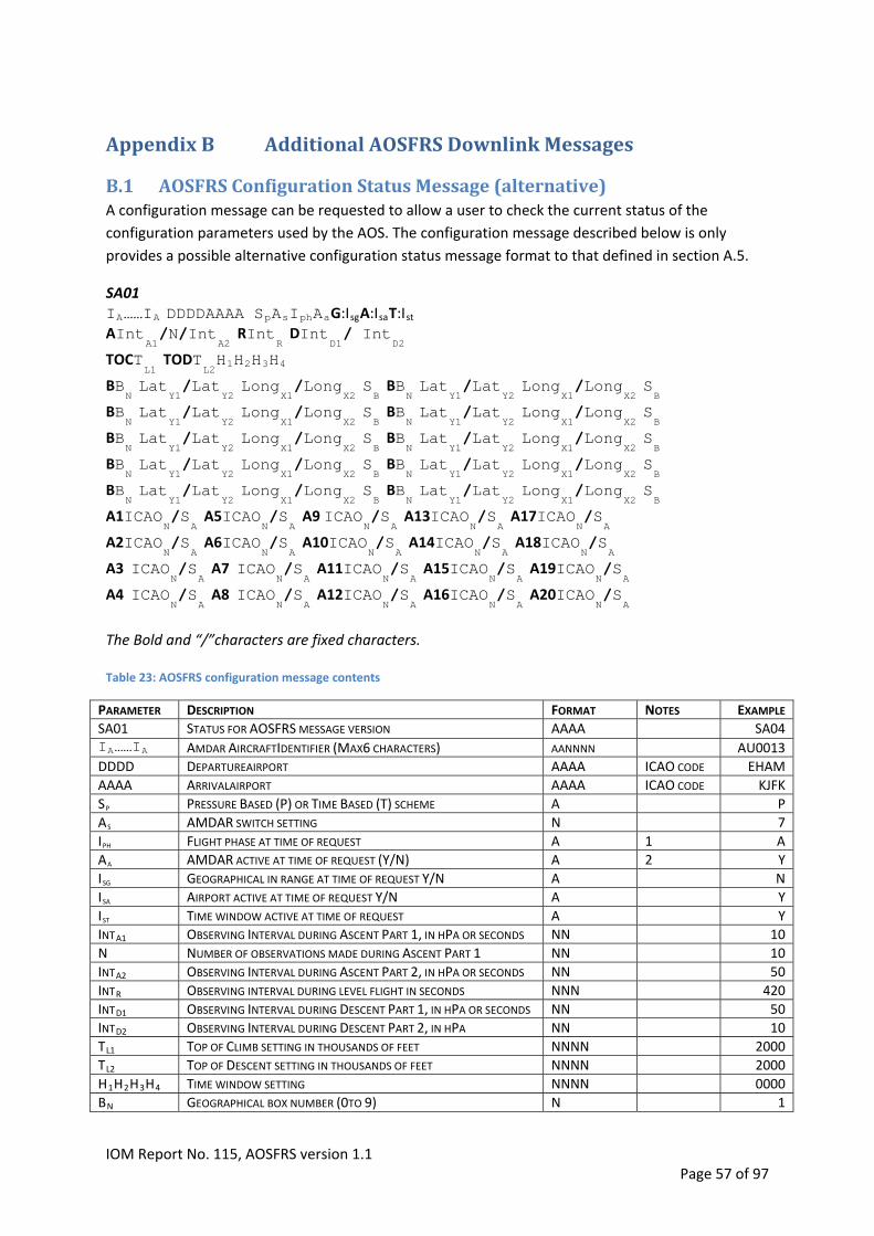
AppendixB AdditionalAOSFRSDownlinkMessages
B.1 AOSFRSConfigurationStatusMessage(alternative)A configuration message can be requested to allow a user to check the current status of the
configuration parameters used by the AOS. The configuration message described below is only
provides a possible alternative configuration status message format to that defined in section A.5.
SA01
IA……IA DDDDAAAA SpAsIphAaG:IsgA:IsaT:Ist
AIntA1/N/Int
A2 RInt
R DInt
D1/ Int
D2
TOCTL1
TODTL2H1H2H3H4
BBN Lat
Y1/Lat
Y2 Long
X1/Long
X2 SB BB
N Lat
Y1/Lat
Y2 Long
X1/Long
X2 SB
BBN Lat
Y1/Lat
Y2 Long
X1/Long
X2 SB BB
N Lat
Y1/Lat
Y2 Long
X1/Long
X2 SB
BBN Lat
Y1/Lat
Y2 Long
X1/Long
X2 SB BB
N Lat
Y1/Lat
Y2 Long
X1/Long
X2 SB
BBN Lat
Y1/Lat
Y2 Long
X1/Long
X2 SB BB
N Lat
Y1/Lat
Y2 Long
X1/Long
X2 SB
BBN Lat
Y1/Lat
Y2 Long
X1/Long
X2 SB
A1ICAO BB
N Lat
Y1/Lat
Y2 Long
X1/Long
X2 SB
N/S
A A5ICAO
N/S
A A9 ICAO
N/S
A A13ICAO
N/S
A A17ICAO
N/S
A
A2ICAON/S
A A6ICAO
N/S
A A A A
A3 ICAO A10ICAO
N/S
A14ICAO
N/S
A18ICAO
N/S
N/S
A A7 ICAO
N/S
A A11ICAO
N/S
A A15ICAO
N/S
A A19ICAO
N/S
A
A4 ICAON/S
A A8 ICAO
N/S
A A12ICAO
N/S
A A16ICAO
N/S
A A20ICAO
N/S
A
The Bold and “/”characters are fixed characters. Table 23: AOSFRS configuration message contents
PARAMETER DESCRIPTION FORMAT NOTES EXAMPLE
SA01 STATUS FOR AOSFRS MESSAGE VERSION AAAA SA04 IA……IA AMDAR AIRCRAFTIDENTIFIER (MAX6 CHARACTERS) AANNNN AU0013
DDDD DEPARTUREAIRPORT AAAA ICAO CODE EHAM
AAAA ARRIVALAIRPORT AAAA ICAO CODE KJFK
SP PRESSURE BASED (P) OR TIME BASED (T) SCHEME A P
AS AMDAR SWITCH SETTING N 7
IPH FLIGHT PHASE AT TIME OF REQUEST A 1 A
AA AMDAR ACTIVE AT TIME OF REQUEST (Y/N) A 2 Y
ISG GEOGRAPHICAL IN RANGE AT TIME OF REQUEST Y/N A N
ISA AIRPORT ACTIVE AT TIME OF REQUEST Y/N A Y
IST TIME WINDOW ACTIVE AT TIME OF REQUEST A Y
INTA1 OBSERVING INTERVAL DURING ASCENT PART 1, IN HPA OR SECONDS NN 10
N NUMBER OF OBSERVATIONS MADE DURING ASCENT PART 1 NN 10
INTA2 OBSERVING INTERVAL DURING ASCENT PART 2, IN HPA OR SECONDS NN 50
INTR OBSERVING INTERVAL DURING LEVEL FLIGHT IN SECONDS NNN 420
INTD1 OBSERVING INTERVAL DURING DESCENT PART 1, IN HPA OR SECONDS NN 50
INTD2 OBSERVING INTERVAL DURING DESCENT PART 2, IN HPA NN 10
TL1 TOP OF CLIMB SETTING IN THOUSANDS OF FEET NNNN 2000
TL2 TOP OF DESCENT SETTING IN THOUSANDS OF FEET NNNN 2000
H1H2H3H4 TIME WINDOW SETTING NNNN 0000
BN GEOGRAPHICAL BOX NUMBER (0TO 9) N 1
IOM Report No. 115, AOSFRS version 1.1 Page 57 of 97
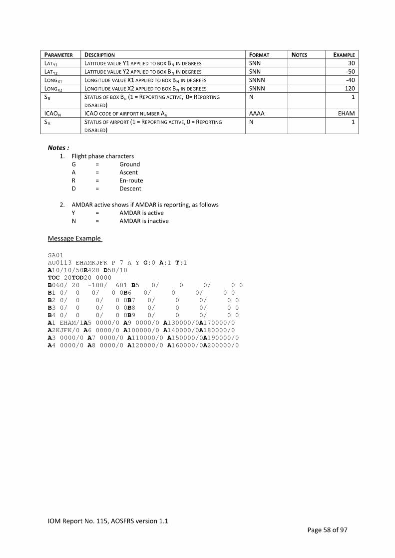
DESCRIPTION FORMAT NOTES EXAMPLE PARAMETER
LATY1 LATITUDE VALUE Y1 APPLIED TO BOX BN IN DEGREES SNN 30
LATY2 LATITUDE VALUE Y2 APPLIED TO BOX BN IN DEGREES SNN ‐50
LONGX1 LONGITUDE VALUE X1 APPLIED TO BOX BN IN DEGREES SNNN ‐40
LONGX2 LONGITUDE VALUE X2 APPLIED TO BOX BN IN DEGREES SNNN 120
STATUS OF BOX BN (1 = REPORTING ACTIVE, 0= REPORTING DISABLED)
N 1 SB
ICAON ICAO CODE OF AIRPORT NUMBER AN AAAA EHAM
STATUS OF AIRPORT (1 = REPORTING ACTIVE, 0 = REPORTING DISABLED)
N 1 SA
Notes :
1. Flight phase characters G = Ground A = Ascent R = En‐route D = Descent
2. AMDAR active shows if AMDAR is reporting, as follows Y = AMDAR is active N = AMDAR is inactive
Message Example SA01 AU0113 EHAMKJFK P 7 A Y G:0 A:1 T:1 A R420 D50/10 10/10/50TOC 20TOD20 0000 B060/ 20 -100/ 601 B5 0/ 0 0/ 0 0 B B 0/ 0 0/ 0 0 1 0/ 0 0/ 0 0 6 B2 0/ 0 0/ 0 0B7 0/ 0 0/ 0 0 B3 0/ 0 0/ 0 0B8 0/ 0 0/ 0 0 B 0/ 0 0/ 0 B9 0/ 0 0/ 0 0 4 0A1 EHAM/1A5 0000/0 A9 0000/0 A130000/0A170000/0 A2KJFK/0 A6 0000/0 A100000/0 A140000/0A180000/0 A A A A A3 0000/0 7 0000/0 110000/0 150000/0 190000/0 A4 0000/0 A8 0000/0 A120000/0 A160000/0A200000/0
IOM Report No. 115, AOSFRS version 1.1 Page 58 of 97

B.2 AOSFRSOptimizationMessageA proposed format for an AOSFRS optimization message is provided below and could be utilized by
an AOS application in the event that an ACARS alternative, such as the OOOI (Out Off On In)
standard reports are not available.
Table B.2‐1
# OF CHAR
CONTENT FORMAT NOTES EXAMPLE CHARACTER NUMBER
1‐6 6 REPORT TYPE INDICATOR NNNNNN “A01OUT” A01OUT
7‐12 6 AMDAR AIRCRAFT IDENTIFIER AANNNN 1 AU0022
13‐14 2 DATE OUT DD DAY OF MONTH 10
15‐18 4 GMT TIME OUT HHMM 1623
19‐22 4 DEPARTUREAIRPORT AAAA 6081
23‐26 4 ARRIVALAIRPORT AAAA 879661
27‐28 2 DATE ETA DD DAY OF MONTH 11
29‐32 4 GMT ETA HHMM 3899
33‐34 2 DATE ESTIMATED OFF DD DAY OF MONTH ; 2 10
35‐38 4 GMT ESTIMATED OFF TIME HHMM 2 ‐525
1. The AMDAR identifier is assigned by the requesting NMHS and should take the form AANNNN, where
AA indicates the country of the AMDAR Program and NNNN is the unique identifier of the aircraft. To
comply with the requirement not to disclose airline proprietary information, the aircraft call‐sign
should not be utilized or revealed within this identifier.
2. Estimated off date and time when available
Example
A01OUTAU0022101623EHAMKLAX110315101650
Aircraft AU0022 has parking brakes off and all doors closed on day 10 at 16:23 GMT, departure
station is Amsterdam flying to Los Angeles, estimated arrival time is on day 11 at 03:15 GMT,
estimated off time is on day 10 at 16:50 GMT
IOM Report No. 115, AOSFRS version 1.1 Page 59 of 97
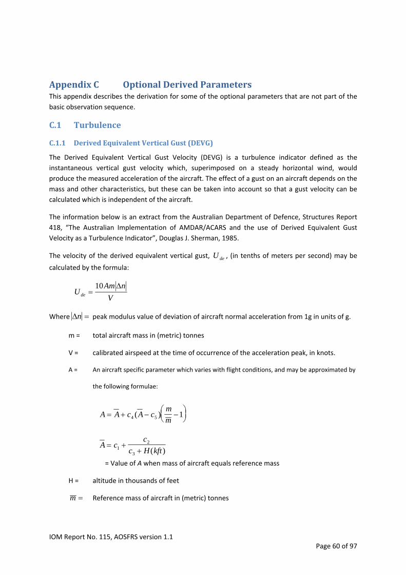
AppendixC OptionalDerivedParametersThis appendix describes the derivation for some of the optional parameters that are not part of the
basic observation sequence.
C.1 Turbulence
C.1.1 DerivedEquivalentVerticalGust(DEVG)
The Derived Equivalent Vertical Gust Velocity (DEVG) is a turbulence indicator defined as the
instantaneous vertical gust velocity which, superimposed on a steady horizontal wind, would
produce the measured acceleration of the aircraft. The effect of a gust on an aircraft depends on the
mass and other characteristics, but these can be taken into account so that a gust velocity can be
calculated which is independent of the aircraft.
The information below is an extract from the Australian Department of Defence, Structures Report
418, “The Australian Implementation of AMDAR/ACARS and the use of Derived Equivalent Gust
Velocity as a Turbulence Indicator”, Douglas J. Sherman, 1985.
The velocity of the derived equivalent vertical gust, , (in tenths of meters per second) may be
calculated by the formula:
U de
V
nAmUde
10
Where n peak modulus value of deviation of aircraft normal acceleration from 1g in units of g.
m = total aircraft mass in (metric) tonnes
V = calibrated airspeed at the time of occurrence of the acceleration peak, in knots.
A = An aircraft specific parameter which varies with flight conditions, and may be approximated by
the following formulae:
A A c A cm
m
4 5 1( )
A cc
c H kft
12
3 ( )
= Value of A when mass of aircraft equals reference mass
H = altitude in thousands of feet
m Reference mass of aircraft in (metric) tonnes
IOM Report No. 115, AOSFRS version 1.1 Page 60 of 97

The parameters depend on the aircraft's typical flight profile. For various aircraft, the
appropriate constants, based on the flight profiles indicated, are shown in Table 24.
c c c1 2 5, , ,
Table24 : DEVG aircraft constants
V1 Vc Mc h1 hc m c1 c2 c3 c4 c5 Aircraft
knot knot Mach ft ft Tonne kft
A300B4 130 300 0.78 5000 30000 120 0.971 2690 79 0.49 19.6
A310 130 300 0.78 5000 35000 120 19.6 574 32 0.52 23.5
A318 120 300 0.78 5000 35000 40 34.7 878 28 0.52 40.3
A319 120 300 0.78 5000 35000 50 33.9 846 29 0.45 39.6
A320-200 120 300 0.78 5000 35000 55 35.9 771 27 0.44 40.7
A321 120 300 0.78 5000 35000 60 34.8 716 28 0.41 39.3
A330-200 120 300 0.82 5000 35000 170 5.88 1010 55 0.44 13.7
A330-300 120 300 0.82 5000 35000 170 5.89 1010 54 0.44 13.6
A340-200 120 300 0.82 5000 35000 190 6.36 949 54 0.41 13.7
A340-300 120 300 0.82 5000 35000 190 6.34 948 54 0.41 13.6
B727 120 300 0.84 5000 30000 50 6.45 4580 83 0.54 37.3
B737-200 120 300 0.73 3000 35000 30 62.0 351 14 0.64 59.4
B737-300 120 300 0.73 3000 35000 40 56.4 328 15 0.56 54.7
B737-400 120 300 0.73 3000 35000 40 56.3 329 15 0.56 54.5
B737-500 120 300 0.75 3000 35000 40 56.4 303 14 0.57 54.3
B737-600 120 300 0.78 3000 35000 40 45.4 420 18 0.57 45.3
B737-700 120 300 0.78 3000 35000 50 42.4 374 19 0.54 42.4
B737-800 120 300 0.78 3000 35000 50 42.2 350 18 0.57 41.9
B747-200 140 300 0.85 5000 40000 250 -2.41 2230 97 0.65 11.5
B747-300 140 300 0.85 5000 40000 200 2.27 1630 81 0.69 13.3
B747-400 140 300 0.85 5000 40000 250 -7.78 3260 120 0.62 10.2
B747SP 140 300 0.85 5000 40000 250 7.44 644 48 0.74 12.4
B757-200 140 300 0.8 3000 40000 100 29.2 298 22 0.55 30
B757-300 140 300 0.8 3000 40000 100 28.9 292 21 0.55 29.7
B767-200 140 300 0.8 3000 40000 110 12.8 918 46 0.65 19.8
B767-300 140 300 0.8 3000 40000 100 13.1 821 42 0.69 19.4
B767-400 140 300 0.8 3000 40000 150 12.9 701 45 0.54 18.3
B777-200 140 300 0.82 3000 40000 170 12.6 198 21 0.72 13.0
B777-300 140 300 0.82 3000 40000 210 13.1 147 19 0.65 12.9
BAC111-200 120 280 0.7 3000 30000 30 55.8 924 27 0.54 60.1
BAC111-475 120 280 0.7 3000 30000 30 50.6 930 28 0.54 55.3
DC10-30 150 300 0.82 5000 30000 200 -6.45 4080 130 0.56 15.0
Electra 100 350 0.7 5000 30000 30 48.9 220 9.1 0.57 41.2
Fokker-100 130 280 0.7 3000 30000 35 52.9 917 27 0.52 57.2
KingAir 100 110 200 0.6 9000 25000 3 70.6 2280 89 0.74 223.
L1011-500 120 300 0.83 5000 35000 150 11.7 712 47 0.59 17.1
IOM Report No. 115, AOSFRS version 1.1 Page 61 of 97

C.1.2 EddyDissipationRate(EDR)
The eddy dissipation rate, ε, is a parameter that quantifies the turbulence intensity within a fluid. In
the context of aircraft turbulence, it is standard practice to refer to ε1/3 as EDR. The advantage of
EDR is that it is an aircraft‐independent measure of the atmospheric turbulence intensity. There are
several ways of estimating EDR (accelerometer‐based versus wind‐based) and they can be
estimated, in principal, along any direction (though usually either vertical or longitudinal [along‐
track] is used).
EDR is the preferred metric to be reported by AMDAR and the AOS should incorporate the reporting
of both a routine or “Heartbeat” EDR observation and also reporting of the 3 event‐based
tions that are “triggered” based on the EDR 1‐minute variables and as described below. observa
C.1.2.1 EDRCalculation
There are different spectral “models” of turbulence that can be used for any of the algorithms:
2 2
2/3 5/32 1
2 2
2 2 2
32
3(1 / )9
( )55 (1 4 / )v
t
t t
L VF f L
V L f
f
1/6V
is the von Karman spectral model, where f is the frequency (Hz), Vt is the aircraft true airspeed
(m/s), α is an empirical constant (taken here to be 1.6), and L is a length‐scale parameter of the
turbulence.
5/32/324( ) 2
55/
tk tf V
VF f
is the Kolmogorov spectral model, which is just the high frequency limit of . Both models
attempt to describe the frequency power spectrum shape of wind data. The von Karman model
better represents the larger scales, especially of the vertical velocity, though it is more complicated
and includes the situational‐dependent length scale L, in addition to EDR (squared). Research
aircraft measurements have shown values of L from about 300 m to 2000 m. For most of the
algorithm implementations to date a mid‐range value of 669 m is used.
vF
The vertical‐wind based technique is discussed in Sharman et. al (2014)6. The main idea is to
compute the vertical winds, and then estimate the EDR from those. This method (as opposed to the
vertical acceleration‐based method) has the advantage of not requiring the aircraft response
function which is difficult to obtain due to its proprietary nature.
sin cos co ncos s siT b bw V Z
is used to compute the vertical winds, where αb is the body‐axis angle of attack, is the pitch angle,
φ is the roll angle, and Z is the inertial vertical velocity. EDR is computed by:
6 Sharman, R. D., L. B. Cornman, G. Meymaris, J. Pearson, and T. Farrar. "Description and derived climatologies
of automated in situ eddy dissipation rate reports of atmospheric turbulence." Journal of Applied Meteorology
and Climatology 2014 (2014). http://dx.doi.org/10.1175/JAMC‐D‐13‐0329.1
IOM Report No. 115, AOSFRS version 1.1 Page 62 of 97

1/2
1/3 1ˆ
ˆ1
h
l
wk
k kh l w
S k
k k S k
where kl and kh are index bounds corresponding to frequency bounds (nominally 0.5 and 3.5 Hz,
respectively, for the current 8 Hz implementations), Sw is the power spectrum of w after time‐series
processing, and is the assumed von Karman spectral model with ε=1, modified to account for
various signal processing artefacts in S
ˆwS
w.
Nominally, the algorithm calculates EDR (ε1/3) over 10 second windows, every 5 seconds. This
provides 12 EDR estimates per minute, from which the actual (confidence weighted) mean and peak
of these estimates are used for downlink. The mean and peak EDRs, along with quality control
metrics, are converted into reporting numbers by use of encoding, which are then reported by
downlink (see section A.2.2.2, Table 20, Note 1). The resolution of both the mean and peak EDR is
0.02.
This document does not specify the requirements for calculation and provision of the EDR 1‐minute
metrics but relies on the specification provided by The National Center for Atmospheric Research
(NCAR), see http://www.ral.ucar.edu/projects/in_situ_software/
For AMDAR EDR reporting, the AOS requires and expects to interface with the external NCAR
software package that provides the EDR 1‐minute variables to the AOS application, which can then
be utilized within the EDR reporting algorithm as defined below in C.1.2.2.
C.1.2.2 EDRReportingAlgorithmandAOSIntegration EDR reporting is based on event‐triggered logic in combination with routine EDR observations. When
an “event” is identified, the logic triggers the downlink of a message. Routine observations are
incorporated in the normal AMDAR message.
Events are of 3 types:
‐ Type 1 (T1): peak EDR ≥ T1 from the last minute. ‐ Type 2 (T2): peak EDR ≥ T2 for at least 3 out of the last 6 minutes. ‐ Type 3 (T3): mean EDR ≥ T3 for at least 4 out of the last 6 minutes.
Because it is important to know that the algorithm is working properly and there is no turbulence,
routine observations are triggered at a specific time interval. These observations are known as
Routine EDR observations. These routine observations are also triggered at takeoff and landing.
Based on the above there are 4 tunable parameters: the three thresholds (T1, T2 and T3), and the
time interval between routine observations (HB). Default values for these parameters are:
‐ T1 = 0.18 peak EDR ‐ T2 = 0.12 peak EDR ‐ T3 = 0.06 mean EDR ‐ HB = 15 minutes.
There are three types of threshold triggers, a follow‐up trigger, and a routine report trigger:
IOM Report No. 115, AOSFRS version 1.1 Page 63 of 97

1. A type 1 report is immediately generated if the latest peak EDR value is above Threshold 1.
2. A type 2 report is generated if (1) is not satisfied and N of the latest NP peak EDRs are above Threshold 2.
3. A type 3 report is generated is (1) and (2) are not satisfied and M of the latest NM mean EDRs are above Threshold 3.
4. A follow‐up report is generated if exactly NP minutes (measurements) have passed since a type 1 or type 2 report.
5. A routine observation is generated if exactly RR minutes have passed since the last routine report (of any type). Additionally, a routine observation is always generated at the beginning (1 minute after the turbulence code startup) and at the end of every flight (triggered when the wheels touch down)7. Routine measurements are interspersed with the normal AMDAR observations ‐ see section A.2, Table 20, Note 1. EDR events can be reported according to the format specified in section A.3.
The NCAR software provides a C software library, the insitu library, that can notify when and how many turbulence/winds/temperature/etc.(met. info) measurements to package into one report for downlink. This assumes that turbulence measurements are being generated from the NCAR in situ turbulence algorithm (TURB). The implementers can incorporate these modules into a software system that samples the TURB algorithm and provides it to the NCAR report triggering algorithm (TURBREP). TURBREP will return a number indicating how many of the previous measurements to downlink. The implementers then downlink the number of met. info measurements as indicated from the NCAR report triggering algorithm. The Turbulence reporting should be integrated into the AMDAR system as follows:
1. The implementers pass data to the TURBREP library both during initialization and normal processing. This includes populating a C structure described in a specified include file (see below) or simply passing float, int, or char data types.
2. The implementers initialize the thresholds for the different triggering events as well as the routine reporting interval. All thresholds should be subject to type1_thresh >= type2_thresh >= type3_thresh>= 0. If this is not met, the initialization routine may return 1, indicating that initialization failed. The current recommended values are 0.18, 0.12, and 0.06, respectively. The hb_interval controls the frequency of the routine reports. The current recommended value is 15 or 20 (minutes). It is advisable that the implementers work with NCAR to determine appropriate values for the thresholds and routine reporting interval if these are not chosen.
3. The implementers always sample the TURB library once every 60 seconds (whether or not that measurement will be reported), as well as the other information required in each line in the reports, namely: pressure altitude, latitude, longitude, GMT time, wind speed and direction, static air temperature, water vapor (if available), peak and mean EDR (TURB), conf (TURB), num bad (TURB), and the turbulence measurement encoded in a 5 char string (TURB). All of this information is to be placed in a circular buffer(s) with length at least 6.
7 when activated, the routine observation generated at the end of flight (ON event) is to be stored and
reported separately from the Touch‐down Observation (see paragraph 3.3.6)
IOM Report No. 115, AOSFRS version 1.1 Page 64 of 97

4. The implementers provide the mean and peak EDR data to TURBREF exactly as passed out of TURB. The implementers set any bad input datum to ISTR_MISSING_DATA as described in a NCAR‐specified include file (see below), if there is some problem that the implementers detects.
5. When reporting measurements, the implementers report the latest available measurements in order from oldest to newest, in the downlinked report. For example, if TURBREP indicates 1 measurement to be reported, then the latest (newest) measurement is put in the report and downlinked. If 2 are to be downlinked then (in order) the second newest and newest measurements are reported.
6. The implementers downlink “routine” reports periodically. The time interval is controlled by the hb_interval parameter in the initialization step (R1). This should typically be set to 15 or 20 minutes. The triggering logic C code initiates these automatically as long as the other requirements in this document are satisfied. The hb_interval can be set to 0, in which case TURBREP will not indicate when to downlink routine reports. It is then the responsibility of the implementers to ensure that the routine reports are downlinked at regular intervals. Routine reports have the same format as triggered reports except that they always contain 1 measurement line.
7. The implementers should trigger an “end of flight” routine report close to but before the aircraft lands (immediately after aircraft touchdown is acceptable and probably the most expedient). There is a corresponding “beginning of flight” routine report, as well but the triggering logic C code initiates that automatically.
8. The implementers should keep track of running maximums of the conf and num_bad which are outputs of TURB. Each turbulence report will contain, in the last turbulence measurement, two encoded characters (the 2nd and 3rd of the 8 turbulence characters) representing these running maximums since the previous downlinked report. For the other measurements in the report, if any, these characters (2nd and 3rd) should be filled with ‘/’, indicating missing values. After the report is generated, the running maximums should be immediately reset. If a reset value needs be chosen, ‐1 is a suitable choice.
9. One potential issue is that it may be possible for a report to be generated after the running maximums have been reset but before TURB outputs new conf and num_bad. For example, suppose at 12:00:00 a turbulence report is triggered, after which the running maximums are reset. If at 12:00:01 the aircraft touches down, the running maximums would still be in a reset stage. If this should occur, i.e. the running maximums are still in a reset state at the time a report is triggered, the characters representing the running maximums in the reports (2nd and 3rd characters) should be represented with ‘:’s.
10. The format of the turbulence measurement, as indicated in section A.2.2.2, Table 20, Note 1, consists of a content indicator character followed by an 8 character string defined below.
IOM Report No. 115, AOSFRS version 1.1 Page 65 of 97
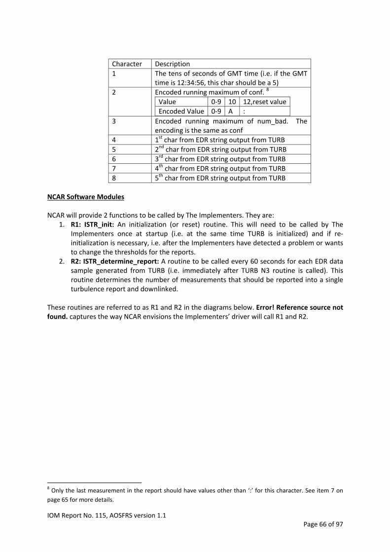
Character Description
1 The tens of seconds of GMT time (i.e. if the GMT time is 12:34:56, this char should be a 5)
Encoded running maximum of conf. 8
Value 0‐9 10 12,reset value
Encoded Value 0‐9 A :
2
3 Encoded running maximum of num_bad. The encoding is the same as conf
1st char from EDR string output from TURB 4
2nd char from EDR string output from TURB 5
3rd char from EDR string output from TURB 6
4th char from EDR string output from TURB 7
5th char from EDR string output from TURB 8
NCAR Software Modules NCAR will provide 2 functions to be called by The Implementers. They are:
1. R1: ISTR_init: An initialization (or reset) routine. This will need to be called by The Implementers once at startup (i.e. at the same time TURB is initialized) and if re‐initialization is necessary, i.e. after the Implementers have detected a problem or wants to change the thresholds for the reports.
2. R2: ISTR_determine_report: A routine to be called every 60 seconds for each EDR data sample generated from TURB (i.e. immediately after TURB N3 routine is called). This routine determines the number of measurements that should be reported into a single turbulence report and downlinked.
These routines are referred to as R1 and R2 in the diagrams below. Error! Reference source not found. captures the way NCAR envisions the Implementers’ driver will call R1 and R2.
8 Only the last measurement in the report should have values other than ‘:’ for this character. See item 7 on
page 65 for more details.
IOM Report No. 115, AOSFRS version 1.1 Page 66 of 97

Implementers Initialization
R1
Impl. gets new EDR data from TURB
(after N3)
Did Thresholds change?
R1YES
R2
Impl. Reports the number of
measurements indicated by R2
Reset running maximums
No
Impl. puts relevant data into circular
buffers
Did R2 return value
> 0
YES
No
Figure 6: Flow diagram for downlinking.
IOM Report No. 115, AOSFRS version 1.1 Page 67 of 97

NCAR Module Interface Argument Lists R1: int ISTR_init(EdrInitStruct ei); Inputs: Thresholds used for triggering Outputs: None Returns: 0 if initialization succeeded 1 if initialization failed – No further processing possible. R2: int ISTR_determine_report(float mnedr,float pkedr,int *num_to_report); Inputs: Latest turbulence data Outputs: Number of measurements to report. 0 indicates no report should be generated. Relevant sections of include files describing interface structures typedef struct { float type1_thresh; float type2_thresh; float type3_thresh; int hb_interval; } EdrInitStruct; #define ISTR_MISSING_DATA ‐9999.0
IOM Report No. 115, AOSFRS version 1.1 Page 68 of 97

C.2 AtmosphericWaterVaporContentDepending on the water vapor sensor installed, the software will be capable of reporting
atmospheric water vapor content for downlink in 3 ways:
1. Mixing ratio (r): defined to be the ratio of the mass of water vapor content to the mass of
dry air of an air sample. The units of r are g/kg.
Resolution: 1 x 10‐6
kg/kg.
Range: 0 to 38 g/kg.
2. Relative humidity (RH): defined to be the density of water vapor present in the atmosphere
expressed as a percentage of the density of water vapor present when the air sample is
saturated (air pressure and temperature held constant). That is:
RH = 100 x (density of actual water vapor / density of saturated water vapor)
Resolution: 0.01%.
Range: 0 to 100%
A WV/Humidity value reported as a relative humidity percentage value is reported in
hundredths of percent and with Q = U, i.e. nnnnnU. For example, 05000U indicates that
water vapor is reported as humidity with a value of 50.00%.
3. Dew point temperature (DPT): the temperature to which air must be cooled in order for it to
become saturated (air pressure held constant. The units of DPT are degrees Celsius (°C).
Resolution: 0.1C
Range: ‐99 to 49C
The software will require a configuration parameter to determine from which sensor the water
vapor content should be acquired and, as a consequence, how the water vapor content should be
encoded.
Water vapor content will be reported in the downlink message as nnnnnQ. Where nnnnn is the
coded water vapor content and Q is a quality control parameter. The value of Q will be dependent
on the type of sensor employed and the units in which the water vapor content is reported.
Table 25 : Water Vapor Configuration Criteria
WATER VAPOR SENSOR CONFIGURATION PARAMETER DOWNLINK FORMAT (NNNNN) QC FORMAT (Q)
WVSS‐II 1 MIXING RATIO SEE TABLE 26
? 2 HUMIDITY U
? 3 DEW POINT TEMPERATURE D
In order to obtain the highest quality water vapor content data on the ground, it is always preferable
to downlink the water vapor sensor output variable as provided rather than converting to one of the
two alternative derived variables, e.g. if the sensor provides mixing ratio, then that is what should be
reported rather than converting to relative humidity or dew point temperature for reporting.
IOM Report No. 115, AOSFRS version 1.1 Page 69 of 97
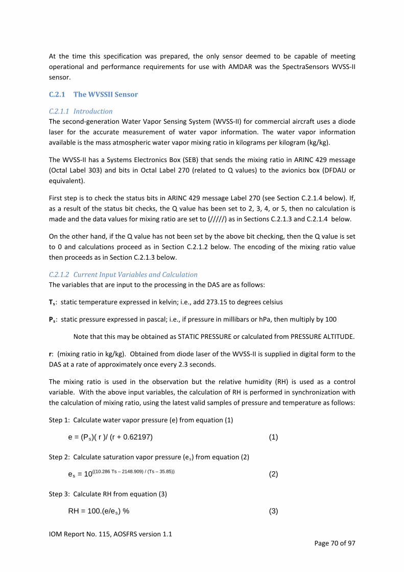
At the time this specification was prepared, the only sensor deemed to be capable of meeting
operational and performance requirements for use with AMDAR was the SpectraSensors WVSS‐II
sensor.
C.2.1 TheWVSSIISensor
C.2.1.1 IntroductionThe second‐generation Water Vapor Sensing System (WVSS‐II) for commercial aircraft uses a diode
laser for the accurate measurement of water vapor information. The water vapor information
available is the mass atmospheric water vapor mixing ratio in kilograms per kilogram (kg/kg).
The WVSS‐II has a Systems Electronics Box (SEB) that sends the mixing ratio in ARINC 429 message
(Octal Label 303) and bits in Octal Label 270 (related to Q values) to the avionics box (DFDAU or
equivalent).
First step is to check the status bits in ARINC 429 message Label 270 (see Section C.2.1.4 below). If,
as a result of the status bit checks, the Q value has been set to 2, 3, 4, or 5, then no calculation is
made and the data values for mixing ratio are set to (/////) as in Sections C.2.1.3 and C.2.1.4 below.
On the other hand, if the Q value has not been set by the above bit checking, then the Q value is set
to 0 and calculations proceed as in Section C.2.1.2 below. The encoding of the mixing ratio value
then proceeds as in Section C.2.1.3 below.
C.2.1.2 CurrentInputVariablesandCalculationThe variables that are input to the processing in the DAS are as follows:
Ts: static temperature expressed in kelvin; i.e., add 273.15 to degrees celsius
Ps: static pressure expressed in pascal; i.e., if pressure in millibars or hPa, then multiply by 100
Note that this may be obtained as STATIC PRESSURE or calculated from PRESSURE ALTITUDE.
r: (mixing ratio in kg/kg). Obtained from diode laser of the WVSS‐II is supplied in digital form to the
DAS at a rate of approximately once every 2.3 seconds.
The mixing ratio is used in the observation but the relative humidity (RH) is used as a control
variable. With the above input variables, the calculation of RH is performed in synchronization with
the calculation of mixing ratio, using the latest valid samples of pressure and temperature as follows:
Step 1: Calculate water vapor pressure (e) from equation (1)
e = (Ps)( r )/ (r + 0.62197) (1)
Step 2: Calculate saturation vapor pressure (es) from equation (2)
es = 10((10.286 Ts – 2148.909) / (Ts – 35.85)) (2)
Step 3: Calculate RH from equation (3)
RH = 100.(e/es) % (3)
IOM Report No. 115, AOSFRS version 1.1 Page 70 of 97

Step 4: Round the RH value to the nearest integer
Add 0.5 to the floating point RH value, and then truncate the value to an integer.
Step 5: IF RH less than 101%, THEN
(i) Present the mixing ratio in the 5‐character code (NNNNN) according to Section C.2.1.3
below.
(ii) Set the control character (Q) in the water vapor information field (NNNNNQ) to Q = 0 (see
Section C.2.1.4 below).
IF RH equal to or greater than 101%, THEN
(i) Present the mixing ratio in the 5‐character code (Section C.2.1.3 below)
(ii) Set Q = 1 (Section C.2.1.4 below)
C.2.1.3 Presentingthe5‐characterMixingRatioFieldThe mass mixing ratio is broadcast from the SpectraSensors WVSSII sensor on ARINC 429 label 303.
For detailed information see SpectraSensors DWG No. 01021‐00027, Rev D or later approved
revisions.
The mass mixing ratio is computed within the WVSS‐II software as a floating point number in kg/kg.
In order to represent this number as an integer variable in the 32‐bit ARINC word, this number is
multiplied by 220 and sent to the avionics box. So in order to use the value needs to be divided by 220
before the data can be encoded.
The water vapor information is presented as a six‐character field (NNNNNQ) where the first five
characters are integers (NNNNN) with the following meaning:
NNNNN = N1N2N3 N4N5= N1 • N2• N3• N4 x 10(-3 – N5)
Example: 12345 = 1234 x 10‐3‐5 = 1234 x 10‐8 kg/kg
C.2.1.4 TheQualityControlCharacter(Q)The value Q is a quality control character and its ultimate nature has the meaning defined in the
Table below.
IOM Report No. 115, AOSFRS version 1.1 Page 71 of 97

Table 26 : WVS‐II Quality Control Parameter
Q System State Software Logic Data Output
Normal operation Air/Ground = Air NNNNN0 0
RH greater than or equal to 101% RH => 101% NNNNN1 1
Input laser power low Laser < 5% of initial power /////2 2
Probe WV temp. input out of range Proprietary information /////3 3
Probe WV pressure input out of range Proprietary information /////4 4
Spectral line out of range Proprietary information /////5 5
Not defined /////6 6
Not defined /////7 7
Numeric error e.g., divide by zero /////8 8
No WVSS installed No WVSS installed /////9 9
The Q values are based upon the information in various bits in the Octal label 270 (message status)
sent by the SEB. This is the first action, to check these bits!
If Bit 13 in label 270 is “1” then laser power is low.
Set Q = 2, data is not computed and the 6 character code is /////2
If Bit 14 in label 270 is “1” then the temperature sensor in the measurement cell is out of range.
Set Q = 3, data is not computed and the 6 character code is /////3
If Bit 15 in label 270 is “1” then the pressure sensor in the measurement cell Is out of range.
Set Q = 4, data is not computed and the 6 character code is /////4
If Bit 16 in label 270 is “1” then the spectral line is out of range.
Set Q = 5, data is not computed and the 6 character code is /////5
When all of the bits (#13 through #16) are zero – that is no problems ‐ calculation is performed as in
Section C.2.1.2 and C.2.1.3. If the calculation is performed without error the data is encoded as in
Section C.2.1.3 and Q is set to 0 (zero). If RH is greater than 100%, then the data is encoded as in
Section C.2.1.3 and Q is set to 1. If a numerical error occurs in the calculations, the data is set to
solidi (/////) and Q is set to 8 – so the 6 character code is /////8.
IOM Report No. 115, AOSFRS version 1.1 Page 72 of 97

AppendixD DataCompression In order to minimize the number of character in a message and thereby reduce transmission cost, two coding compression techniques can be applied to the message contents. The first compression technique relies on expressing reported values as integers and then coding these integer numeric values using the full set of available printable characters. These are the characters available within ACARS as shown in Table 27 below. By using this technique, the number of characters required to report the numerical values is reduced, thereby saving valuable and costly space in downlink messages. The second compression technique can be applied to some parameters only and relies on encoding an initial reference, “absolute” value, after which subsequent values reported in the same message are encoded as the difference between the initial Absolute value and the subsequent parameter value. This difference between the reference value and the reported value is referred to as the “delta” value. Parameters that can be reported in this way rely on having the physical characteristic that they change relatively predictably and slowly from one value to the next. In the case of the AMDAR application, it is the spatial parameters that most lend themselves to such a compression technique. The application of Base‐40 compression or Delta‐Compression, and, in some cases, both techniques to some parameters, can result in significant data transmission cost savings. Section D.1 below describes the Base‐40 Compression technique, Section D.2 describes the Delta‐Compression technique and Section D.3 provides the compressed format for the AOSFRS Downlink Data Message Format as defined in section A.2.
D.1 Base‐40Compression Base‐40 Compression can be used to express integer values using the character set provided below in Table 27. In its simplest utilization, the Base‐40 character set allows a single digit to be used to express the integers from 0 up to 39. The integer 40 is then expressed with 2 characters as ‘10’. What this means is: 1 count of 40 and zero. Mathematically: (1*40) + 0 41 is represented by 11, 42 by 12, etc. Similarly, ‘.0’ = (39*40) + 0 = 1560 and ‘..’ = (39*40) + 39 = 1599. Thus, including ‘ 0’, Base‐40 allows 1600 integers to be encoded with only 2 characters spaces.
IOM Report No. 115, AOSFRS version 1.1 Page 73 of 97
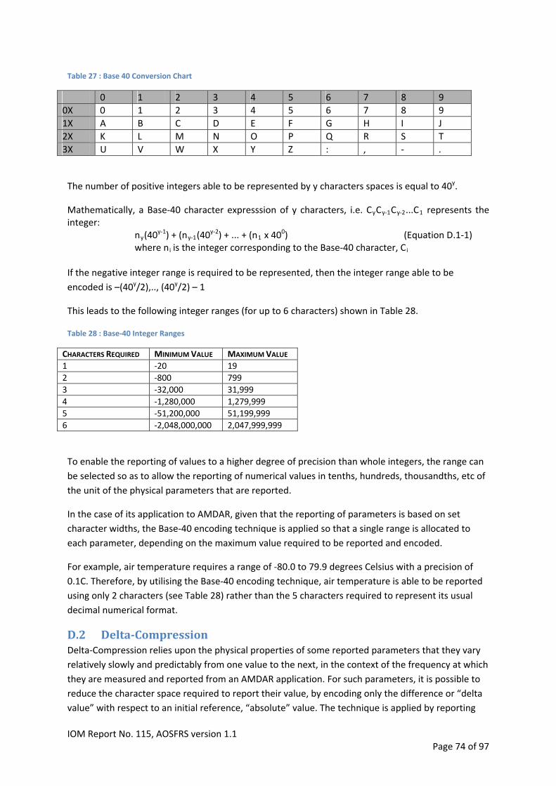
Table 27 : Base 40 Conversion Chart
0 1 2 3 4 5 6 7 8 9
0X 0 1 2 3 4 5 6 7 8 9
1X A B C D E F G H I J
2X K L M N O P Q R S T
3X U V W X Y Z : , ‐ .
The number of positive integers able to be represented by y characters spaces is equal to 40y.
Mathematically, a Base‐40 character expresssion of y characters, i.e. CyCy‐1Cy‐2...C1 represents the integer:
ny(40y‐1) + (ny‐1(40
y‐2) + ... + (n1 x 400) (Equation D.1‐1)
where ni is the integer corresponding to the Base‐40 character, Ci If the negative integer range is required to be represented, then the integer range able to be
encoded is –(40y/2),.., (40y/2) – 1
This leads to the following integer ranges (for up to 6 characters) shown in Table 28.
Table 28 : Base‐40 Integer Ranges
CHARACTERS REQUIRED MINIMUM VALUE MAXIMUM VALUE
1 ‐20 19
2 ‐800 799
3 ‐32,000 31,999
4 ‐1,280,000 1,279,999
5 ‐51,200,000 51,199,999
6 ‐2,048,000,000 2,047,999,999
To enable the reporting of values to a higher degree of precision than whole integers, the range can
be selected so as to allow the reporting of numerical values in tenths, hundreds, thousandths, etc of
the unit of the physical parameters that are reported.
In the case of its application to AMDAR, given that the reporting of parameters is based on set
character widths, the Base‐40 encoding technique is applied so that a single range is allocated to
each parameter, depending on the maximum value required to be reported and encoded.
For example, air temperature requires a range of ‐80.0 to 79.9 degrees Celsius with a precision of
0.1C. Therefore, by utilising the Base‐40 encoding technique, air temperature is able to be reported
using only 2 characters (see Table 28) rather than the 5 characters required to represent its usual
decimal numerical format.
D.2 Delta‐CompressionDelta‐Compression relies upon the physical properties of some reported parameters that they vary
relatively slowly and predictably from one value to the next, in the context of the frequency at which
they are measured and reported from an AMDAR application. For such parameters, it is possible to
reduce the character space required to report their value, by encoding only the difference or “delta
value” with respect to an initial reference, “absolute” value. The technique is applied by reporting
IOM Report No. 115, AOSFRS version 1.1 Page 74 of 97

absolute values in an initial reference observation, after which subsequent observations in the same
message are reported with delta values for those parameters to which the compression technique is
applicable. Both the absolute (reference) values and the delta values are reported with Base‐40
Compression. The original absolute values of the non‐reference observations are able to be
reconstructed with a simple numerical addition by the ground processing system.
The AMDAR parameters for which such a technique is applied are the spatial and time coordinates:
Latitude, Longitude and Day/Time.
D.3 AOSFRSCompressedDownlinkDataMessageFormatThe compressed downlink data message format is very similar in structure to the uncompressed
downlink format (section A.1). It is comprised of a Header block (Table 29), followed by a sequence
of data observations, each of which contain all of the parameter values making up the Basic
Observations (Table 30), followed by those additional Optional Parameters (Table 31) that may be
reported. The fundamental differences are:
1. The first observation of the message must be the reference observation that contains the
absolute values corresponding to those parameters for which the Delta‐Compression
technique is applied;
2. Subsequent observations contain the delta values for those parameters for which the Delta‐
Compression technique is applied; and,
3. Those parameters for which Base‐40 Compression is applicable (as indicated in Tables 30
and 31) are encoded as described in section D.1 (examples are provided below in section
D.4).
As with the uncompressed message format, the number of observations reported in each message
should be based on those considerations outlined in section 3.5.
Table 29 : Header, compressed
CHARACTER NUMBER
# OF CHAR CONTENT FORMAT NOTES LINE NUMBER
1 1‐3 3 AMDAR MESSAGE VERSION E.G. “A01”
2 1‐26 1 TO 26 OPTIONAL PARAMETER INDICATION # OR A THRU Z SEE OPTIONAL PARAMETERS
3 1‐7 8 AMDAR AIRCRAFT IDENTIFIER AANNNN 1
3 8 1 NORMAL (N) OR COMPRESSED (C) C 2
9 1 TIME BASED (0) OR PRESSURE BASED SCHEME (1)
0 OR 1 3
3 10‐13 4 DEPARTUREAIRPORT AAAA 3
3 14‐17 4 ARRIVALAIRPORT AAAA 3
Notes:
1. The AMDAR identifier is assigned by the requesting NMHS.
2. C indicates that the data is encoded using the compression scheme.
3. Departure and Arrival airport are represented by their ICAO code. Reporting of these fields is optional
but if available, strongly recommended.
IOM Report No. 115, AOSFRS version 1.1 Page 75 of 97
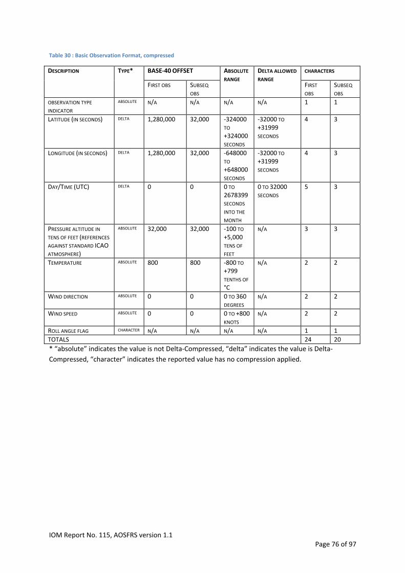
Table 30 : Basic Observation Format, compressed
BASE‐40 OFFSET CHARACTERS DESCRIPTION TYPE*
FIRST OBS SUBSEQ OBS
ABSOLUTE RANGE
DELTA ALLOWED
RANGE FIRST OBS
SUBSEQ OBS
ABSOLUTE N/A N/A N/A N/A 1 1 OBSERVATION TYPE
INDICATOR DELTA 1,280,000
32,000 ‐324000
TO
+324000 SECONDS
‐32000 TO +31999 SECONDS
4 3 LATITUDE (IN SECONDS)
DELTA 1,280,000
32,000 ‐648000 TO
+648000 SECONDS
‐32000 TO +31999 SECONDS
4 3 LONGITUDE (IN SECONDS)
DELTA 0
0 0 TO 2678399 SECONDS
INTO THE
MONTH
0 TO 32000 SECONDS
5 3 DAY/TIME (UTC)
PRESSURE ALTITUDE IN TENS OF FEET (REFERENCES AGAINST STANDARD ICAO
ATMOSPHERE)
ABSOLUTE
32,000
32,000
‐100 TO +5,000 TENS OF
FEET
N/A 3 3
TEMPERATURE ABSOLUTE 800 800 ‐800 TO +799 TENTHS OF
°C
N/A 2 2
WIND DIRECTION ABSOLUTE 0 0 0 TO 360 DEGREES
N/A 2 2
WIND SPEED ABSOLUTE 0 0 0 TO +800 KNOTS
N/A 2 2
ROLL ANGLE FLAG CHARACTER N/A N/A N/A N/A 1 1
TOTALS 24 20
* “absolute” indicates the value is not Delta‐Compressed, “delta” indicates the value is Delta‐
Compressed, “character” indicates the reported value has no compression applied.
IOM Report No. 115, AOSFRS version 1.1 Page 76 of 97

Table 31 : Optional parameters, compressed
BASE‐40 OFFSET CHARACTERS DESCRIPTION TYPE
FIRST OBS SUBSEQ OBS
ABSOLUTE RANGE
DELTA ALLOWED
RANGE SUBSEQ OBS
FIRST OBS
CHARACTER N/A N/A N/A N/A 0, 1 OR 9*
0,1 OR 9* EDR
ABSOLUTE 0 0 0 TO 800 TENTHS
M/S
N/A 2 2 DEVG
TRUE AIRSPEED ABSOLUTE 0 0 0 TO 999 N/A 3 3
TRUE HEADING (TENTHS OF DEGREES)
ABSOLUTE 0 0 0 TO 3599 N/A 3 3
GNSS ALTITUDE ABSOLUTE 100 100 ‐100 TO +5,000 TENS OF
FEET
N/A 3 3
ANTI‐ICE ABSOLUTE 0 0 0 TO 7 N/A 1 1
A/C CONFIGURATION INDICATOR
ABSOLUTE 0 0 0 TO 15 N/A 1 1
WATER VAPOR CHARACTER N/A N/A N/A N/A 4 4
WATER VAPOR QUALITY CHARACTER N/A N/A N/A N/A 1 1
ICING ABSOLUTE 0 0 0 TO 2 N/A 1 1
ROLL ANGLE ABSOLUTE 180 180 ‐180 TO 180 DEGREES
N/A 2 2
PITCH ANGLE ABSOLUTE 90 90 ‐90 TO 90 DEGEREES
N/A 2 2
VERTICAL SPEED ABSOLUTE 2000 2000 ‐2000 TO 2000 FT/MIN
N/A 3 3
26+9* 26+9* TOTALS
* If the observation is a routine EDR observation, the total number would be 26+9=35; or 26+1=27; otherwise
the total would be 26.
D.4 EncodingCompressedValuesThe steps required to compress data values in Tables 30 and 31 are:
1. Determine either the numerical value or the delta value to be reported. For example, if the parameter is time, the value to be reported is the delta time value of the first day of the month at 15:07:00 and the absolute (reference) time was the first day of the month at 15:00:00, then the delta value to be encoded is: 420 (seconds).
2. If necessary, convert the numerical value to be encoded into an integer that provides the required precision in terms of tenths, hundredths, thousandths, etc of the units in which the parameter is reported. For example, an air temperature value of 15.5°C is converted to the integer 155.
3. Add the Base‐40 Offset (from the appropriate column in Tables 30 and 31) to the integer value, which accounts for the negative part of the numerical range of the parameter. For example, for an air temperature value of 15.5°C, which is converted to integer value 155, the final integer value to be encoded is 155 + 800 = 955.
4. Based on the range in Table 28 that corresponds to the number of characters indicated in column Character, convert the integer value (from step 3) into its Base‐40 equivalent. Examples showing how to carry out the conversion manually are shown below – of course, a
IOM Report No. 115, AOSFRS version 1.1 Page 77 of 97

computational algorithm for automating this process as part of a data processing system should be implemented.
5. The character string produced in step 4 is the value that is reported in the message. Note:
When an automated algorithm attempts to encode an integer value that lies outside of the designated range, the algorithm should return and report a string of solidii characters of equivalent length.
When encoding Base‐40 strings, unused character space should be left‐padded with blank spaces.
The following 2 examples of Base‐40 Compression use different algorithms and mathematical
functions for the final step required to convert the integer value to a Base‐40 character string. Both
are valid and programmable alternative algorithms.
COMPRESSION EXAMPLE 1: To code latitude 3º43’30’’ South in seconds
Step 1 (if required) Convert value into the required units, in this case seconds South = ((3 x 3600) + (43 x 60) + 30) x (‐1) = ‐13,410 seconds Step 2 The Absolute Range for Latitude specifies that 4 characters are utilized to provide the required range of values and an offset of 1,280,000 is used (see Table 30). Step 3 Add the required offset to the value to get the coded value: Coded value = ‐13,410 + 1,280,000 = 1,266,590 Step 4 Convert the coded value into its base 40 equivalent using Table 27:
Character 1 (most significant): Trunc (1,266,590/ (403)) = 19 check Table 2719 = J Remainder = 1,266,590 ‐ (19 x 403) = 50590 Character 2 Trunc (50,590/(402)) = 31check Table 2731 = V Remainder = 50,590 ‐ (31 x 402) = 990 Character 3 Trunc (990/(401)) = 24check Table 2724 = O
Remainder = 990 ‐ (24 x 401) = 30 Character 4 (least significant) check Table 2730 = U
CODED CHARACTER STRING = JVOU COMPRESSION EXAMPLE 2:
Pressure Altitude is measured at 38,990 feet.
Step 1 (if required) Convert value into the required units, in this case tens of feet: 38,990 / 10 = 3,899 Step 2
IOM Report No. 115, AOSFRS version 1.1 Page 78 of 97

According to table 24 the Base‐40 offset for pressure altitude is 32,000 and three characters are used. Add the required offset to get the input value: Input value = 3,899 + (403)/2 = 3,899 + 32,000 = 35,899 Step 3 Convert the coded value in to base 40 using Table 27: if input value >= 40 then
least significant output character = MOD(input value,40) = 19 check Table 2719 = J input value =INT( input value /40) = 897
if input value >= 40 then repeat the first step second output character = MOD(input value,40) = 17 check Table 2721 = H input value = INT(input value /40) = 22
The input value is no longer >= 40, the most significant output character is M (corresponding to 22)
CODED CHARACTER STRING = MHJ
Compressed report example
A01 # AZ0001N1EHAMKJFK 0 L-A Q.KXOO8 UKHKKPKPG 100K00K00K0W0HKQUKPG 100K00K00K0XKHKQUKPG 100K00K00K0Z0HKQUKPG 100K00K00K0:KHKQUKPG 100K00K00KKO0HKQUKPG 100K00K00KM7KHKQUKPG 300K00K00KM7KHKQUKPG A report with an invalid parameter (in this case Wind Direction not valid) A01 # AZ0001N1EHAMKJFK 0 L-A Q.KXOO8 UKHK//KPG 100K00K00K0W0HK//KPG 100K00K00K0XKHK//KPG 100K00K00K0Z0HK//KPG 100K00K00K0:KHK//KPG 100K00K00KKO0HK//KPG 100K00K00KM7KHK//KPG 300K00K00KM7KHK//KPG
D.5 DecodingCompressedValuesThe steps for decoding a value that has been compressed using the method outlined in section D.4
are:
1. Convert the Base‐40 string to its (base 10) integer equivalent by applying Equation D.1‐1.
2. Subtract the Base‐40 integer offset from the integer obtained in step 1.
IOM Report No. 115, AOSFRS version 1.1 Page 79 of 97

3. If necessary, convert the integer to its decimal value in the units in which it was originally
measured (e.g. for air temperature, divide the integer by 10).
4. If this is a value to which Delta‐Compression has been applied, add the absolute (reference)
value from the reference (first) observation to the delta value.
IOM Report No. 115, AOSFRS version 1.1 Page 80 of 97

AppendixE PlatformSpecificInformationThis chapter provides information on systems from various vendors, relevant to the development of
AMDAR. The information is based on vendor input and user experience. If you find anything in this
chapter missing or incorrect please contact the WMO.
E.1 HoneywelldatasystemsHoneywell AMDAR/ARINC620 Compatible Hardware and Software
Product name HW part number Core software PN AOC/application PN
ACARS 965‐0728‐xxx Note 1 998‐1375‐508 or newer
Note 2
CMU 965‐0758‐xxx Note 1 998‐2141‐509 or newer
Notes 3, 4
ATSU Any HPS compatible
with the AOC is
acceptable
Note 5 998‐2459‐505 or
998‐2794‐501 or newer
Note 4
Notes:
Note 1: Any core software compatible with the AOC is acceptable.
Note 2: Standard Application Operational Software, 998‐1375‐508. Modified to replace version 1 of
the ARINC 620 Meteorological Weather Reporting Function with Version 2. Some bugs were found
and fixed in later releases.
Note 3: Standard Application Operational Software 998‐2141‐509. Modified to replace version 1 of
the ARINC 620 Meteorological Weather Reporting Function with Version 2. Some bugs were found
and fixed in later releases.
Note 4: Earlier software contains ARINC 620 version 1.
Note 5: Any host platform software (HPS) compatible with the AOC is acceptable. Delta BDS and
ACMS database may be required to provide data.
If upgrading existing software, then the latest version is recommended.
In many cases the DFDAU needs to be programmed to provide 429 data to ACARS/CMU/ATSU.
IOM Report No. 115, AOSFRS version 1.1 Page 81 of 97
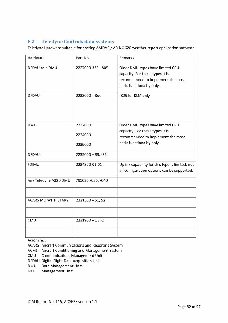
E.2 TeledyneControlsdatasystemsTeledyne Hardware suitable for hosting AMDAR / ARINC 620 weather report application software
Hardware Part No. Remarks
DFDAU as a DMU 2227000‐335, ‐805 Older DMU types have limited CPU
capacity. For these types it is
recommended to implement the most
basic functionality only.
DFDAU 2233000 – 8xx
‐825 for KLM only
2232000
2234000
2239000
Older DMU types have limited CPU
capacity. For these types it is
recommended to implement the most
basic functionality only.
DMU
DFDAU 2235000 – 83, ‐85
FDIMU 2234320‐01‐01 Uplink capability for this type is limited, not
all configuration options can be supported.
Any Teledyne A320 DMU 795020 /030, /040
ACARS MU WITH STARS 2231500 – 51, 52
CMU 2231900 – 1 / ‐2
Acronyms: ACARS Aircraft Communications and Reporting System ACMS Aircraft Conditioning and Management System CMU Communications Management Unit DFDAU Digital Flight Data Acquisition Unit DMU Data Management Unit MU Management Unit
IOM Report No. 115, AOSFRS version 1.1 Page 82 of 97

IOM Report No. 115, AOSFRS version 1.1 Page 83 of 97
AppendixF AvionicsInformationForm This form is intended to gather information on avionics systems available that may allow AMDAR to
be implemented onboard an aircraft. The form can be used when it is not immediately clear to the
airline or met engineer if the available systems are capable of hosting AMDAR. The information can
be send to the WMO who will then try to find out if the systems mentioned in the form are capable
and in what way.
The information the WMO is after are types and manufacturers of the onboard data acquisition
systems, communication systems and other systems that may be relevant.
The form allows for one aircraft type. If more aircraft types need to be specified, please copy and
paste the table for as much types as required. The table headers are described below.
Operator: Aircraft Operator
Aircraft Type: Type of aircraft the system is installed on (e.g. B747‐400, A340‐300, C56Xetc)
# of A/C: The number of aircraft involved
LRU name: Name of the LRU (Line Replaceable Unit) (e.g. DFDAU, ATSU,CMU etc.)
Manufacturer: Name of LRU Manufacturer (e.g. Honeywell, Sagem, Teledyne etc.)
LRU P/N: Acquisition system LRU Part Number
Software P/N: If known, acquisition system software Part Number
S/W Control: Who controls/programs the acquisition system software
(Manufacturer/Operator/Other)
OPERATOR:
AIRCRAFT TYPE: # OF A/C:
LRU NAME MANUFACTURER LRU P/N SOFTWARE P/N S/W CONTROL

AppendixG AOSFRSApplicationsDevelopmentRequirementsSpecificationThis Appendix provides a table that can be used to define and provide specific requirements for AMDAR onboard software applications development and for software
developers to indicate which of these requirements they can comply with.
Requirement Section Mandatory/ Recommended/ Optional
Requested (Y/N)
Developer Compliant
(Y/N)
Comments
H.1. The onboard Data Acquisition System (DAS) shall provide a data interface to the highest quality data sources available from the aircraft.
3.1 Mandatory
H.2. Parameters to be acquired/derived from the avionics system: AIRCRAFT ID AIR/GROUND SWITCH OR WEIGHT ON WHEELS COMPUTED AIR SPEED DATE – DAY GMT – HOURS GMT – MINUTES GMT – SECONDS LATITUDE LONGITUDE PRESSURE ALTITUDE IN ICAO STANDARD ATMOSPHERE STATIC AIR TEMPERATURE STATIC PRESSURE WIND DIRECTION TRUE WIND SPEED ROLL ANGLE PITCH ANGLE
Table 1 Mandatory
H.3. Parameters recommended to be acquired/derived from the avionics system: DEPARTURE STATION DESTINATION STATION VERTICAL SPEED GROSS WEIGHT VERTICAL ACCELERATION
Table 2 Recommended

Requirement Section Mandatory/ Requested Developer Comments Recommended (Y/N) Compliant/ Optional (Y/N)
H.4. Optional parameters to acquired/derived from the avionics system: WATER VAPOR DATA EDR ICING DATA ANTI‐ICE AIRCRAFT CONFIGURATION INDICATOR FLAPS GEAR DOWN/UP GNSS ALTITUDE GROUNDSPEED TRUE TRACK TRUE HEADING TRUE AIRSPEED
Table 3 Optional
H.5. Data Acquisition Rate:
Input data acquired more than once per second. Last valid sample within that second is used
Input data acquired less than once per second, the last valid sample is used.
3.2.1 Mandatory
H.6. Data Validation: Input data is only used when
It is validated using applicable avionics standards
It passes Out of Range Checks
3.2.2 Mandatory
H.7. Data that is invalid shall not be used in any calculation 3.2.2 Mandatory
H.8. Invalid data shall be either not reported or masked as specified 3.2.2 Mandatory
H.9. All values, unless specifically stated, shall be obtained or calculated from the highest frequency instantaneous sample available, closest to the observation time and subject to Data Validation requirements. No smoothing or averaging of parameters
3.2.3 Mandatory
H.10. AMDAR Observation intervals should be linked to aircraft flight phase. 3.2.4.1 Recommended
H.11. Flight phases that should be recognized:‐ Ground, Ascent, Level flight (or Cruise or En‐route), Descent
3.2.4.1 Recommended
IOM Report No. 115, AOSFRS version 1.1 Page 85 of 97

Requirement Section Mandatory/ Requested Developer Comments Recommended (Y/N) Compliant/ Optional (Y/N)
H.12. Assessment of the Phase of Flight to be made at regular one second intervals
3.2.4.1 Recommended
H.13. Flight phase Ascent shall always follow Phase Ground for a minimum of 60 seconds
3.2.4.1 Mandatory
H.14. A turbulence metric should be derived and reported within the AMDAR observation
3.2.4.2 Recommended
H.15. Turbulence metric should be either:‐ ‐ Eddy Dissipation Rate (EDR) [preferred] and/or ‐ Derived Equivalent Vertical Gust (DEVG)
3.2.4.2 Recommended
H.16. Water Vapour/Relative Humidity/Dew Point may be reported 3.2.4.3 Optional
H.17. A Roll Angle Flag should be reported with the AMDAR observation 3.2.4.4 Recommended
H.18. A derived parameter representing the aircraft configuration status may be added to the meteorological observation data. When used, the parameter shall be assigned a value according to Table 5.
3.2.4.5 Optional
H.19. AMDAR observations are only to be made during the Ascent, Level Flight and Descent flight phases
3.3 Mandatory
H.20. Observations shall be made either:‐ ‐ when a pre‐set static pressure level is reached (Pressure based scheme, Preferred) ‐ When a pre‐set time period has elapsed (Time based scheme)
3.3 Mandatory
H.21. AMDAR software shall be capable of switching between Pressure Based scheme and a Time Based Scheme, but only one scheme shall be active at a time
3.3 Mandatory
H.22. AMDAR observations shall be stored in a dedicated area of memory until required
3.3 Mandatory
H.23. The downlink message shall contain a header block, containing:‐ AMDAR MESSAGE VERSION OPTIONAL PARAMETERS INDICATOR AMDAR AIRCRAFT IDENTIFIER DATA COMPRESSION STATE TIME/PRESSURE SCHEME INDICATOR
A.2
Table 18
Mandatory
IOM Report No. 115, AOSFRS version 1.1 Page 86 of 97

Requirement Section Mandatory/ Requested Developer Comments Recommended (Y/N) Compliant/ Optional (Y/N)
DEPARTURE AIRPORT ARRIVAL AIRPORT
H.24. The downlink message shall contain a Data Block with each observation on a new line. Each line to be right justified. The observations should contain the Basic Observation Sequence:‐ OBSERVATION TYPE INDICATOR LATITUDE (in seconds) LONGITUDE (in seconds) DATE TIME ALTITUDE (in 10s of feet) STATIC AIR TEMPERATURE (in 0.1C) WIND DIRECTION WIND SPEED ROLL ANGLE FLAG All parameters shall be right justified
A.3
Table 19
Mandatory
H.25. For each optional parameter that is added to the observation sequence, the Header Indicator associated with the optional parameter shall be added in line 2 in the header
A.3.2 Mandatory
H.26. The downlink message may contain any from the optional parameters:‐EDR DEVG TRUE AIRSPEED TRUE HEADING GNSS ALTITUDE ANTI‐ICE A/C CONFIGURATION WATER VAPOUR RELATIVE HUMIDITY ICING
Table 20 Optional
H.27. An Ascent Observation shall be stored at the time of the OFF event, this is Ascent Observation Initial. This observation shall consist of the Basic Observation Sequence and any additional parameters to be reported
3.3.1 Mandatory
IOM Report No. 115, AOSFRS version 1.1 Page 87 of 97

Requirement Section Mandatory/ Requested Developer Comments Recommended (Y/N) Compliant/ Optional (Y/N)
Table 6
H.28. When reported in the downlink, the Ascent Initial Observation should be identified by the Observation Type Indicator
3.3 3.3.1
Recommended
H.29. Ascent observations shall consist of the Basic Observation Sequence and any additional parameters to be reported
3.3.2 Mandatory
H.30. Ascent observations should be identified by the Observation Type Indicator
3.3.2 Recommended
H.31. Descent observations shall consist of the Basic Observation Sequence and any additional parameters to be reported
3.3.3 Mandatory
H.32. Descent observations should be identified by the Observation Type Indicator
3.3.3 Recommended
H.33. Routine Observations are made at set and configurable time intervals and, when enabled, should be made during all phases of flight.
3.3.4 Recommended
H.34. Routine Observations shall consist of the Basic Observation Sequence and any additional parameters to be reported.
3.3.4 3.3.4.1 3.3.4.2 3.3.4.3
Mandatory
H.35. Routine Observations should be identified by the Observation Type Indicator
3.3.4 Recommended
H.36. Maximum Wind Observation should be reported when the conditions in 3.3.4.4 are met. If reported, the Maximum Wind Observation should be identified by the Observation Type Indicator and shall consist of the Basic Observation Sequence and any additional parameters to be reported at the time of
the maximum wind measurement.
3.3.4.4 Recommended
H.37. Mean and peak turbulence intensity (EDR –eddy dissipation rate) should be calculated for each minute in flight. If reported, EDR Routine Observations should be identified by the Observation Type Indicator and should be concatenated to the Basic Observation Sequence.
3.3.5 Recommended
IOM Report No. 115, AOSFRS version 1.1 Page 88 of 97

Requirement Section Mandatory/ Requested Developer Comments Recommended (Y/N) Compliant/ Optional (Y/N)
H.38. The Touch‐down Observation shall be stored at the time of the ON event. Touch‐down Observations should be identified by the Observation Type Indicator and shall consist of the Basic Observation Sequence and any additional parameters to be reported.
3.3.6 Mandatory
H.39. During the ascent and descent phases of flight, the triggering of Ascent and Descent Observations should be made based on either a Pressure Based Scheme or a Time Based Scheme as defined in Table 8.
3.4 Recommended
H.40. En‐route Routine Observations should also be triggered at set time intervals and should begin at the conclusion of the ascent phase and terminate when reporting of Descent Observations begins.
3.4 Recommended
H.41. During the Ascent Flight Phase, Ascent Observations shall be made at defined Ambient Static Pressure levels which will be known as "Ascent Target Pressures". These will be referenced to the Ambient Pressure at take‐off.
3.4.1.1 Mandatory
H.42. At the time of take‐off, the Ambient Static Pressure shall be determined using procedure in 3.4.1.1.1.Error! Reference source not found.
3.4.1.1.1 Mandatory
H.43. An initial Ascent Observation shall be made and stored at the time of the OFF event (take‐off).
3.3.4.1 Mandatory
H.44. Ascent Observations during Ascent Part 1 shall be made according to the procedure in 3.4.1.1.3.
3.4.1.1.3 Table 8 Table 9
Mandatory
H.45. Ascent Observations during Ascent Part 2 shall be made according to the procedure in 3.4.1.1.4.
3.4.1.1.4 Table 8 Table 9
Mandatory
H.46. Routine observations shall be made at set time intervals during flight phase ascent as determined in 3.4.1.1.5.
3.4.1.1.5 Mandatory
Pressure Based
Schem
e
H.47. During Phase of Flight Descent, Observations shall be made 3.4.1.2 Mandatory
IOM Report No. 115, AOSFRS version 1.1 Page 89 of 97

Requirement Section Mandatory/ Requested Developer Comments Recommended (Y/N) Compliant/ Optional (Y/N)
according to the procedures in 3.4.1.2.
H.48. The Touch‐Down observation should be made and stored
according to the procedures in 3.4.1.2.1
3.4.1.2.1 Recommended
H.49. Routine observations shall be made at set time intervals during flight phase descent. The interval timer resets and commences following each observation. If no pressure level change is encountered during the preset time interval, an observation is triggered and the timer is reset.
3.4.1.2.2 Mandatory
H.50. An initial Ascent Observation is triggered at the “OFF” event. 3.4.2.1.1 Mandatory
H.51. Following the Initial observation, observations are accumulated at set time intervals until the part #1 duration limit is reached, counted from the “OFF” event.
3.4.2.1.2 Table 8
Mandatory
H.52. Observations are accumulated from the expiration of the Part #1 data acquisition period. Part #2 data observations are taken at set time intervals until the Ascent total duration limit is reached, counted from the “OFF” event.
3.4.2.1.3
Table 8
Mandatory
H.53. Descent data measurements begin at Top of Descent and are accumulated at a set time interval. Top of Descent is modifiable.
3.4.2.2 Table 8
Mandatory
Time Based
Schem
e
H.54. An observation is stored as close as possible but before the aircraft touches down. This observation is included as the last observation in the last descent message
3.4.2.2.1 Mandatory
H.55. When a pre‐set or maximum allowable number of observations are stored, a message shall be formed containing these observations. After a message is transmitted, the observations can be discarded. The message shall provide at least the following information:
‐ Identification as AMDAR data ‐ Software version indicator i.e. what specification it conforms to‐ Reporting scheme (time‐based or pressure‐based) ‐ All required AMDAR Observations ‐ Any other information required to decode and reform data at
3.5.1 Mandatory
IOM Report No. 115, AOSFRS version 1.1 Page 90 of 97
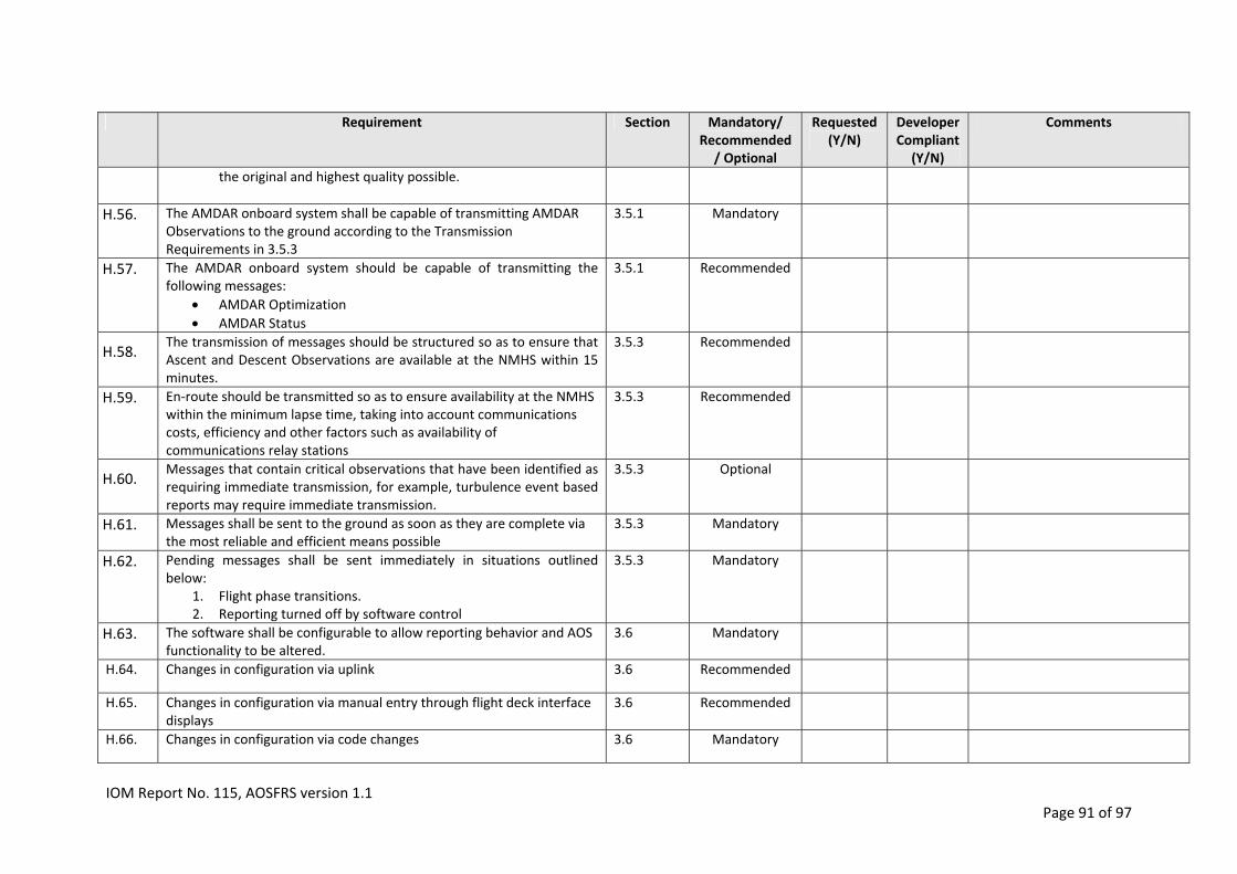
Requirement Section Mandatory/ Requested Developer Comments Recommended (Y/N) Compliant/ Optional (Y/N)
the original and highest quality possible.
H.56. The AMDAR onboard system shall be capable of transmitting AMDAR Observations to the ground according to the Transmission Requirements in 3.5.3
3.5.1 Mandatory
H.57. The AMDAR onboard system should be capable of transmitting the following messages:
AMDAR Optimization
AMDAR Status
3.5.1 Recommended
The transmission of messages should be structured so as to ensure that Ascent and Descent Observations are available at the NMHS within 15 minutes.
3.5.3 Recommended H.58.
H.59. En‐route should be transmitted so as to ensure availability at the NMHS within the minimum lapse time, taking into account communications costs, efficiency and other factors such as availability of communications relay stations
3.5.3 Recommended
Messages that contain critical observations that have been identified as requiring immediate transmission, for example, turbulence event based reports may require immediate transmission.
3.5.3 Optional H.60.
H.61. Messages shall be sent to the ground as soon as they are complete via the most reliable and efficient means possible
3.5.3 Mandatory
H.62. Pending messages shall be sent immediately in situations outlined below:
1. Flight phase transitions. 2. Reporting turned off by software control
3.5.3 Mandatory
H.63. The software shall be configurable to allow reporting behavior and AOS functionality to be altered.
3.6 Mandatory
H.64. Changes in configuration via uplink 3.6 Recommended
H.65. Changes in configuration via manual entry through flight deck interface displays
3.6 Recommended
H.66. Changes in configuration via code changes 3.6 Mandatory
IOM Report No. 115, AOSFRS version 1.1 Page 91 of 97

Requirement Section Mandatory/ Requested Developer Comments Recommended (Y/N) Compliant/ Optional (Y/N)
H.67. Apart from the Reporting On/Off switch (section 3.6.2.1 for specific requirements), changes to the configuration by one of the methods described above should become permanent until changed again.
3.6 Recommended
H.68. If for whatever reason the configuration settings are lost, the settings shall revert to a default configuration.
3.6 Mandatory
H.69. The default configuration setting is recommend to be “All flight phases on”,
3.6.2.1 Recommended
H.70. The AOS should support the functionality to modify the Reporting on/off configuration settings both permanently and also for a number (N = 1 to 99) of flights, after which the configuration reverts to the default setting.
3.6.2.1 Optional
H.71. If the AOS is not to be controlled by a ground‐based AMDAR data optimization system, then changes to this configuration setting should be permanent
3.6.2.1 Recommended
H.72. If requirement H.70 is not able to be met and the AOS is to be controlled by a ground‐based AMDAR data optimization system, then changes to this configuration setting should not be permanent and the switch should revert to the default setting at the conclusion of each flight. It should be understood that, unless this requirement is met, the optimization system will either need to keep track of the reporting status or else an uplink command must be sent in response to every flight notification
3.6.2.1 Recommended
H.73. The AOS shall be configurable so that a minimum of 10 geographical boxes in which reporting is enabled or disabled. Outside these boxes reporting is disabled depending on the airport limitation (see 3.6.2.3)
3.6.2.2 Mandatory
H.74. The AOS should be configurable so that a minimum of 20 and up to 50 airports around which reporting for ascent, descent or both, can be enabled or disabled. The settings applied to these specific locations shall take priority over the geographical limiting function
3.6.2.3
Table 15
Recommended
H.75. It should be possible to configure a single time window during which reporting is inhibited. This setting has priority over all other settings except reporting off
3.6.2.4 Recommended
IOM Report No. 115, AOSFRS version 1.1 Page 92 of 97

Requirement Section Mandatory/ Requested Developer Comments Recommended (Y/N) Compliant/ Optional (Y/N)
H.76. If EDR reporting is implemented, it should be possible to switch off EDR event reporting and alter the settings for the threshold values as per 3.6.2.5.
3.6.2.5
Table 17 Recommended
H.77. The software should provide for a message that lists the current settings for all of the control parameters mentioned in previous paragraph. The message can be requested via either or both (in order of preference)
1. An uplink command. 2. Manual request through flight deck interface displays
3.6.3
8.1
Recommended
H.78. AOSFRS Downlink Message Format A.2 Recommended
H.79. Header Block format A.2.1, Table 18
Recommended
H.80. Data Block format A.2.2 Recommended
H.81. Data Block format, Basic Observation Sequence format A.2.2.1, Table 19
Recommended
H.82. Data Block format, Optional Parameter Sequence format A.2.2.2, Table 20
Recommended
H.83. EDR Event Message format A.3, Table 21, Table 22
Recommended
H.84. AOSFRS Configuration Functionality and Uplink Control, Basic Configuration
A.4.1, Table A.4.1
Recommended
H.85. AOSFRS Configuration Functionality and Uplink Control, Extended Configuration, Geographical Control Boxes
A.4.2.1, Table
Recommended
IOM Report No. 115, AOSFRS version 1.1 Page 93 of 97

Requirement Section Mandatory/ Requested Developer Comments Recommended (Y/N) Compliant/ Optional (Y/N)
A.4.2.1‐1
H.86. AOSFRS Configuration Functionality and Uplink Control, Extended Configuration, Airport Configuration Parameters
A.4.2.2, Table A.4.2.2‐1
Recommended
H.87. AOSFRS Configuration Functionality and Uplink Control, Extended Configuration, Routine Observations and Wind Reporting Status
A.4.2.3, Table A.4.2.3‐1
Recommended
H.88. AOSFRS Configuration Functionality and Uplink Control, Extended Configuration, Ascent Configuration Parameters
A.4.2.4, Table A.4.2.4‐1
Recommended
H.89. AOSFRS Configuration Functionality and Uplink Control, Extended Configuration, Descent Configuration Parameters
A.4.2.5, Table A.4.2.5‐1
Recommended
H.90. AOSFRS Configuration Status Message format A.5, Table A.5‐1
Recommended
H.91. AOSFRS Configuration Status Message (alternative) format B.1, Table 23
Optional
H.92. An AMDAR optimization message may be sent to the NMHS and/or airline prior to departure of every flight
3.6.4 B.2
Optional
H.93. Base 40 data compression can be used to reduce message size (and communications costs)
D.1 D.2
Optional
H.94.
H.95.
IOM Report No. 115, AOSFRS version 1.1 Page 94 of 97

IOM Report No. 115, AOSFRS version 1.1 Page 95 of 97
Requirement Section Mandatory/ Recommended/ Optional
Requested (Y/N)
Developer Compliant
(Y/N)
Comments
H.96.
H.97.

AppendixH AOSFRSVersionControl
VERSION DATE OF VERSION DESCRIPTION
Version 1.0 July 16 2013 Specifies version 1.0 of the AMDAR Onboard Software Functional Requirements Specification. The preliminary draft version of this specification was developed under the consultancy of Mr Frank Tamis, Aircraft Data Engineering & Consultancy and reviewed and finalized for publication by the WMO Commission for Instruments and Methods of Observations (CIMO) Task Team on Aircraft‐based Observations.
Version 1.1 2 April 2014 1. Section 1.2: 2nd paragraph added relating to version 1.1. 2. Section 1.6: 2 acronyms added (AOSFRS, AEEC). 3. Section 2.3: 2nd to last paragraph added describing
intention to make ARINC 620 Meteorological Report Version 6 consistent with AOSFRS Version 1.1
4. Section 2.3.1: First paragraph modified to reflect consistency between AOSFRS and ARINC 620 and recommend latest versions of these specification as standards for AOS; Data Handling paragraph altered for clarity.
5. Section 3.1, Paragraph 2: Reference is changed to a footnote and updated.
6. Table 1: Correction to 2nd equation of Note 1. 7. Table 1: roll angle added; pitch angle added. 8. Table 3: EDR added. 9. Table 6: precision requirement for Latitude and
Longitude clarified as 1 second. 10. Section 3.6.2.2: Requirement regarding disabled
reporting to take precedence over enabled reporting for geographical boxes.
11. Appendix A: a. Title changed. b. Added section title A.2 c. Table 19: Latitude and longitude precision
specified as second; format adjusted accordingly.
d. Table 20, Note 1: text change for clarification and added description of the EDR encoding.
e. Table 20, Note 2: new table added for specifying extended reporting of Anti‐ice parameter; roll angle added; pitch angle added; vertical speed added.
f. Table 22: Precision of latitude and longitude corrected to 1 second and formats adjusted accordingly.
g. Added A.4 AOSFRS Configuration Functionality and Uplink Control for expected consistency with ARINC 620‐S8.
h. Added A.5 AOSFRS Configuration Status Message for expected consistency with ARINC 620‐S8.
IOM Report No. 115, AOSFRS version 1.1 Page 96 of 97

IOM Report No. 115, AOSFRS version 1.1 Page 97 of 97
VERSION DATE OF VERSION DESCRIPTION
12. Section C.1.2 a. Added paragraph to C.1.2 describing EDR; b. C.1.2.1: Renamed and added several paragraphs
providing the mathematical formulae for calculation of EDR; and,
c. C.1.2.1: Renamed and added several paragraphs describing the integration of EDR reporting into the AOS.
13. Section D.3: a. Table 31: altered GNSS offset to 100; roll angle
added; pitch angle added; vertical speed added. 14. Section B.1: Change to 1st paragraph to clarify B.1 as
providing an alternative configuration status message format.
15. Section B.2: Change to 1st paragraph to clarify that B.2 provides an alternative optimization message in the case that OOOI reports are unavailable.
16. Appendix D: Considerable text added and changes made for clarification and provision of more detailed explanation of data compression techniques.
17. Added Appendix G, AOSFRS Applications Development Request and Compliance Matrix
18. AOSFRS Version Control updated and became Appendix H.


