Embed Size (px)
Citation preview

1
1
AMB Systems Short Course
In Cooperation with the International Symposium of
Magnetic Bearings (ISMB 17) - August 18-21, 2021
Industrial Applications Compressors, Turbines, Motors, Generators, Turbo Generators,
Refrigeration Compressors, Energy Storage Flywheels, Canned Pumps, Artificial Heart Pumps, Subsea Oil/Gas Production
Topics
Magnetic Bearing Operating Principles Amplifiers, Decoupled Tilt-Translate PID Controls
Flexible Rotor AMB Systems, Notch Filters, Unbalance Rejection Know Your AMB System, Model Verification
Digital Controller Specifications, Modern Controls Sensitivity Functions, API/ISO Standards
Auxiliary Bearing Design, Rotor Drop Modeling
Part 1: Dates: Mon/Tues/Wed August 2/3/4, 2021
Lecture Times: 1:00 – 4:00 GMT – Local Times 6:00 – 9:00 California, 9:00-12:00 Washington, 10:00-13:00 Rio de Janeiro,
14:00-17:00 London, 15:00-18:00 Central Europe, 21:00-24:00 Beijing, 22:00-1:00 Tokyo
Part 2: Additional Talks - Thursday August 5, 2021
Basic and Advanced Magnetic Bearing Systems – Design and Industrial Applications
Presented By: Rotor Bearing Solutions International August 2-5, 2021
− 2 per axis
− analog input ⚫ Selection depends on bearing design
− 2 per axis
− analog input ⚫ Selection depends on bearing design
2
2
Course Description, Objectives, and Lecturers
The course will be presented online with Zoom, as set up by RBSI, at the times listed above. Questions can be asked of the lecturers
via the Zoom calls.
This magnetic bearing systems short course is intended for engineering staff
of companies interested in advanced understanding or using magnetic bearings. The
use of magnetic bearings is increasing in industrial applications but they are often not well
understood by mechanical engineers. This course will provide an introductory as well as
an advanced training program in magnetic bearing systems and controls. Details of several
industrial applications of magnetic bearings industrial machines are presented in the
course.
Part 1: A significant part of the course is the detailed controls design in rigid
rotor/AMB systems using the decoupled rotor center of gravity coordinates. Additional
topics on modern control for flexible shaft-AMB machines such as high pressure
compressors and surge control in compressors using magnetic bearings are presented.
API/ISO specifications for magnetic bearing supported rotating machines are presented.
The automated design of magnetic thrust and radial bearings is presented to design the
smallest bearing to supply the desired load capacity, while including the user’s desired
materials, coil wire, shaft diameter, and other parameters. The magnetic circuit
parameter design method is then automatically verified with a finite element model. Such
parameters as current gain, open loop stiffness, power loss and others are automatically
evaluated.
Part 2: The details of auxiliary bearing design using cageless, non-contact, ceramic
ball bearing design with spring and damping components is provided. A nonlinear time-
transient rotor dynamic analysis of method of AMB system rotor drops on auxiliary
bearings are presented. Several cases of industrial examples are provided and compared to
measured values for a few rotors. These three additional lectures are presented as an
option on Monday, August 5, as indicated below.
The use of mathematics in this short course is at a medium level for both electrical and mechanical engineers. It is assumed that the attendees have at least some minimum experience with magnetic bearings and controls but not at a high level.

3
3
______________________________________________________________________________________________
AMB Systems Short Course Detailed Talk
Descriptions – Part 1
_____________________________________________________
Day 1 Monday, August 2, 2021 - Lecture Times: 1:00 – 4:00 GMT
Session 1 – Overview/Design of Magnetic Bearings Talk 1: Introduction to Magnetic Bearings – Allaire’s Notes 5.1 - Parts 1&2 This talk presents the basic configuration and operating principles of magnetic bearings. The
magnetic bearing properties of supporting a single mass rotor in a non-contact manner is discussed.
The basics of magnetic circuits are presented – including airgaps, magnetic poles, coil windings,
coil/pole inductance, load capacity.
Talk 2: Introduction to Magnetic Bearing PID Control – Allaire’s Notes 5.2&Motor
Compressor This talk presents the concepts of magnetic bearing control gain and open loop stiffness.
Proportional, integral and derivative (PID) controls parameters as applied to a rigid rotor are

4
4
developed with examples. An example rigid rotor motor compressor, illustrated below, on
magnetic bearings is discussed.
Break
Session 2 – Design/Build/Test of High Speed Turbo Aerator Talk 3: Design/Test/Build Magnetic Bearing for High Speed Turbo Aerator This talk presents the magnetic bearing suspension development for a 27,000 rpm centrifugal
turbine driving a generator for waste heat energy conversion, as illustrated below, for Kinetic
Traction in California. The magnetic bearing detailed design and installation in the turbo aerator
is discussed in detail.
Talk 4: Levitation Testing and AMB Control for High Speed Turbo Aerator The vertically oriented turbo aerator was levitated and extensively tested for minimum rotor
amplitude and control currents. The controls method is discussed and advanced unbalance
rejection control was successfully applied. The flexible machine substructure was tested and
otor earing olutions u hou alboom lectric
otor ompressor agnetic earing ro ect

5
5
control notch filters used to avoid exciting the substructure natural frequencies. The detailed
control electronics, such as the control DSP shown below, and methodology is presented.
Day 2 Tuesday, August 3, 2021 - Lecture Times: 1:00 – 4:00 GMT
Session 3 – Control Standards and Sensitivity Functions
Talk 5: Control and Sensitivity Functions – ISO and API Standards Magnetic bearing control systems have standards for the best operating points based upon sensitivity
functions and system stability. These standards have been adopted by the International Standards
Organization (ISO) and the American Petroleum Institute (API). This talk presents the sensitivity function
standards now in common use in the AMB industry. Session 4 – Rigid Rotor AMB Modeling, Stability and Controls
Talk 6: Industry Standard Rigid Rotor Controls – Decoupled Tilt/Translate - PID Control The most common AMB controls method around the world is rigid rotor decoupled tilt-translate control for
rigid rotors – rotors operating below the rotor first critical speed. The method of decoupling the equations of
motion for a rotor center of gravity (CG) coordinate system, as illustrated below, is presented in detail. Issues
are the 1) non-collocation of the sensors and actuators, 2) decoupling the AMB open loop stiffness terms. 3) low
pass filters for the PID controller, amplifiers and sensors, as well as 4) rotor gyroscopic effects. Sensitivity
functions are employed to insure a well-designed control system. An example industrial AMB supported motor
is presented to illustrate the decoupling process.
ilt and ranslate
6
6
Break
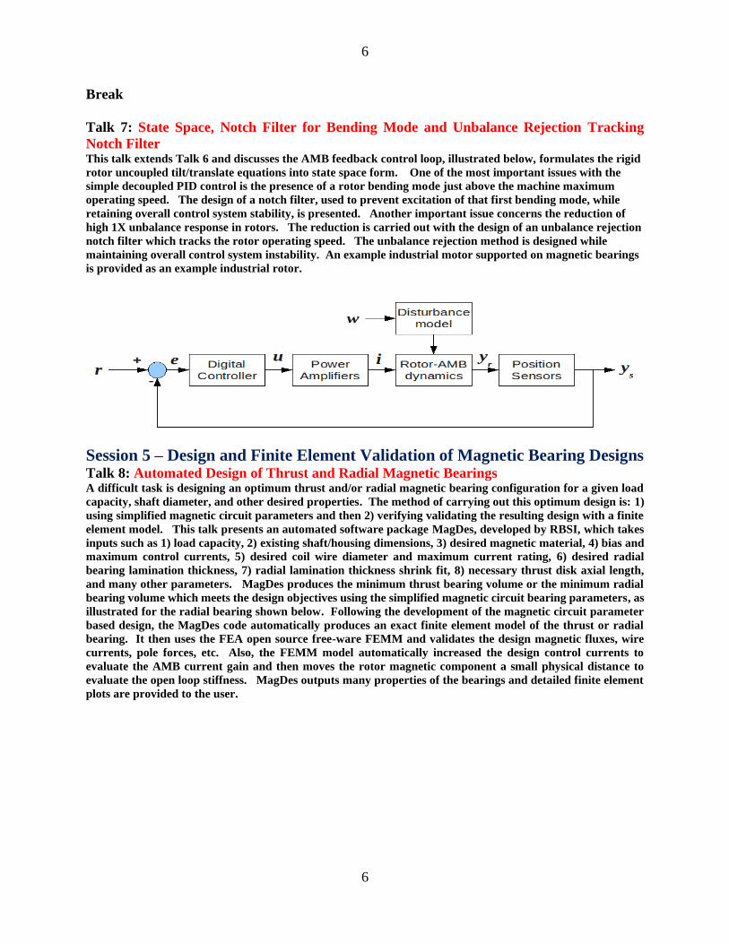
Talk 7: State Space, Notch Filter for Bending Mode and Unbalance Rejection Tracking
Notch Filter This talk extends Talk 6 and discusses the AMB feedback control loop, illustrated below, formulates the rigid
rotor uncoupled tilt/translate equations into state space form. One of the most important issues with the
simple decoupled PID control is the presence of a rotor bending mode just above the machine maximum
operating speed. The design of a notch filter, used to prevent excitation of that first bending mode, while
retaining overall control system stability, is presented. Another important issue concerns the reduction of
high 1X unbalance response in rotors. The reduction is carried out with the design of an unbalance rejection
notch filter which tracks the rotor operating speed. The unbalance rejection method is designed while
maintaining overall control system instability. An example industrial motor supported on magnetic bearings
is provided as an example industrial rotor.
Session 5 – Design and Finite Element Validation of Magnetic Bearing Designs Talk 8: Automated Design of Thrust and Radial Magnetic Bearings A difficult task is designing an optimum thrust and/or radial magnetic bearing configuration for a given load
capacity, shaft diameter, and other desired properties. The method of carrying out this optimum design is: 1)
using simplified magnetic circuit parameters and then 2) verifying validating the resulting design with a finite
element model. This talk presents an automated software package MagDes, developed by RBSI, which takes
inputs such as 1) load capacity, 2) existing shaft/housing dimensions, 3) desired magnetic material, 4) bias and
maximum control currents, 5) desired coil wire diameter and maximum current rating, 6) desired radial
bearing lamination thickness, 7) radial lamination thickness shrink fit, 8) necessary thrust disk axial length,
and many other parameters. MagDes produces the minimum thrust bearing volume or the minimum radial
bearing volume which meets the design objectives using the simplified magnetic circuit bearing parameters, as
illustrated for the radial bearing shown below. Following the development of the magnetic circuit parameter
based design, the MagDes code automatically produces an exact finite element model of the thrust or radial
bearing. It then uses the FEA open source free-ware FEMM and validates the design magnetic fluxes, wire
currents, pole forces, etc. Also, the FEMM model automatically increased the design control currents to
evaluate the AMB current gain and then moves the rotor magnetic component a small physical distance to
evaluate the open loop stiffness. MagDes outputs many properties of the bearings and detailed finite element
plots are provided to the user.

7
7
Day 3 Wednesday, August 3, 2021 - Lecture Times: 1:00 – 4:00 GMT
Session 7 – Flexible Rotor AMB Stability and Controls Talk 9: Design and Characterization of Flexible, High Speed Rotor on Active Magnetic
Bearings This Talk presents the design and measured characterization of a large, high speed, flexible rotor test rig.
The purposes of the test rig were 1) modern control with s representation, 2) simulation of a multistage, high
pressure industrial centrifugal compressor with a balance piston seal, as illustrated below, introducing
unstable cross coupled stiffness near the center of the rotor, 3) operation of the test rig above the normal
instability initiation speed using the mu synthesis control to keep it stable. The test rig had two support
AMBs and two excitation AMBs. The electronic control system hardware used to implement the control is
presented In many multistage industrial compressors, the numerical value of the cross coupled stiffness is not
well known so it’s numerical value is considered to be uncertain in this test rig. The interior (between AMBs)
excitation AMB was used to input the simulated seal cross coupled stiffness instability source near the rotor
center. The other AMB was used to provide a sinusoidal excitation sweep of the operating rotor/AMB
system while operating at high speed. An important part of this talk is the comparison between the modeling
and measured properties of the operating rotor/AMB/control system to show that the modeling is accurate
prior to proceeding to the final testing, given the following talk.
ara eter alue
s a S a ia eter
la ina on otor a ina on
bac iron Stator 2 2
actuator ctuator engt
ain ain ole ire urns
auxiliar uxiliar ole ire urns 2
uadrant otal ire urns uadrant 2
des ign erturba on urrent
des ign esign orce 2

8
8
Talk 10: Mu Synthesis Control of Flexible, High Speed Rotor Operating Above First
Critical Speed This Talk presents the advanced Mu Synthesis AMB control approach used to control the large, flexible, high
speed rotor in the test rig, as illustrated below, described in the previous talk at operating speeds well above
the first rotor bending mode. One feature of Mu Synthesis is that it is designed to implement the control
with some system uncertainties – meaning that an approximate numerical value of the uncertain parameter is
known but that value may vary by as much as 50% to 100%. The Mu Synthesis controller requires the
control designer to establish the rotor location of the uncertain seal cross coupled stiffness and a suitable
performance weighting function for the controller to employ. Also, some other system uncertainties, such as
rotor gyroscopic effects, were taken into account in a similar manner. While the simulated seal cross coupled
stiffness numerical value was known, the Mu Synthesis control was not provided that information and had to
consider the unknown cross coupled stiffness, near the rotor center, as uncertainty. The rotor operated
through the rotor bending critical speed and up to the maximum system speed of 18,000 rpm. Quite a few
measurements were recorded for this test rig and discussed in this talk in detail.
Break
Session 8 – Centrifugal Compressor Surge Test Rig and Control Talk 11: Design, Construction and Initial Testing of Surge Control Test Rig This Talk, and Talk 12, are concerned with a test rig, as shown below, for a high speed motor driven industrial centrifugal compressor with axial magnetic bearing control used to eliminate surge. Surge, induced by closing the discharge flow control valve, creates transmission line acoustic gas flow waves which push flow back into the compressor impeller/shroud area and generate very high level pressure waves. The compressor impeller was moved back and forth but a sinusoidal reference input to the thrust AMB with the proper frequency to cancel the high pressure surge acoustic waves. The design of the testing system is presented, along with the initial motor magnetic radial bearings operating as a rigid rotor. The AMB system control properties are described in detail.
9
9
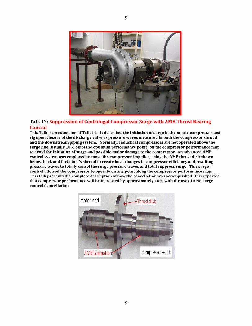
Talk 12: Suppression of Centrifugal Compressor Surge with AMB Thrust Bearing Control This Talk is an extension of Talk 11. It describes the initiation of surge in the motor-compressor test rig upon closure of the discharge valve as pressure waves measured in both the compressor shroud and the downstream piping system. Normally, industrial compressors are not operated above the surge line (usually 10% off of the optimum performance point) on the compressor performance map to avoid the initiation of surge and possible major damage to the compressor. An advanced AMB control system was employed to move the compressor impeller, using the AMB thrust disk shown below, back and forth in it’s shroud to create local changes in compressor efficiency and resulting pressure waves to totally cancel the surge pressure waves and total suppress surge. This surge control allowed the compressor to operate on any point along the compressor performance map. This talk presents the complete description of how the cancellation was accomplished. It is expected that compressor performance will be increased by approximately 10% with the use of AMB surge control/cancellation.

10
10
End of Basic and Advanced Magnetic Systems short Course ____________________________________________________________
Design and Performance Analysis of Auxiliary Bearings
Part 2 – Additional Talks
Day 4 Thursday, August 5
Talk 13: Design of Auxiliary Bearings for Rotor Drop This Talk provides an introduction to auxiliary bearing design for AMB systems. Magnetic bearing systems
are highly reliable. However, situations can occur when 1) electric power fails (in spite of the backup battery),
2) high loads enter the system and overload one or more AMBs, 3) non-rotating machine components may move
and provide strong rubs to the rotor, 4) other problems can occur. All high speed rotating machines on AMBs
are provided with auxiliary bearings to assist in keeping the rotor off of the non-rotating machine components.
The relatively low cost auxiliary bearings are normally designed to fail due to contact instead of the very
expensive rotor. Usually, the auxiliary bearings are designed to survive a minimum number of drops, such as
5 or 6, prior to replacement. The rotor drop analysis consists of a nonlinear rotor/auxiliary bearing dynamic
analysis. Rotors can be either horizontal (compressor or motor) or vertical (energy storage flywheel). A
schematic diagram of a rotor drop analysis is provided. Typical auxiliary bearing types include rolling element
bearings, plain bearings, planetary bearings, zero clearance auxiliary ball or roller bearings, permanent
magnets. By far, the most common auxiliary bearings are ball bearings. RBSI has worked with Cerobear, a
prominent German ball bearing manufacturing firm, to provide double row angular contact bearings with
silicon nitride ceramic balls and no cage, as shown in the following diagram. It has a one piece inner ring and
a preload on the separated outer races. The clearance between the shaft and the auxiliary bearing inner race
is set at ½ of the AMB radial clearance. The angular contact rolling element auxiliary bearings have a
compliant substructure, as described in this talk. This support structure provides stiffness and damping
properties, supplied by a stack of Bellville washers and a wavy spring.
Talk 14: Rotor Drop Analysis of a Vertical Axis Energy Storage Flywheel with Replacement
Aux Bearings
This Talk describes the nonlinear transient rotor drop of an industrial energy storage flywheel, as shown below,
on newly designed auxiliary bearings using the configuration described in Talk 13. The original auxiliary

11
11
bearings, with 10 mm bore and steel balls, but without any flexible damped supports, failed on the first drop
each time and had to be replaced after each drop. The non-linear transient analysis presented here evaluates
all of the balls, including all 12 degrees of freedom, in the auxiliary bearings as they accept the rotor loads. A
flywheel finite element rotor model, involving axial and lateral displacements, was established and employed
in the drop analysis. A rotor undamped critical speed map was evaluated. The original auxiliary bearings
were 10 mm bore balls. The rotor/auxiliary bearing axial motions were evaluated and found to be relatively
small. However, the original aux bearing maximum compressive stresses during drop, without support stiffness
and damping components, were found to be approximately 5x10^9 Pa in inner race and 3x10^9 Pa in the outer
race. The maximum yield stress of the original steel balls was 2.0x10^9 Pa, which showed why they failed
during the first drop. The replacement Cerobear ceramic double row bearings used much larger bore balls at
40mm. Also, they had flexible damped supports, as described in Talk 13, such that the contact force during
drop reduced from 9,000n in the original bearings to 1,000N in the new bearings. The maximum stress in the
new aux bearings was reduced to 1.35x10^9 Pa in the inner race and 1.1x10^9 Pa in the outer race. The full,
nonlinear transient rotor drop displacements were evaluated and the results presented in this talk. The shaft
speed reduction and the aux bearing inner race increased rotating speeds were evaluated and shown in this
talk. The ball motions were evaluated. The final result, due to the auxiliary bearing redesign and the nonlinear
transient rotor drop modeling result produced a new rotor drop system in the energy storage flywheel that has
been very successful and provides an expected 5 to 6 rotor drops before the aux bearings need to be replaced.
Break
Talk 15: Rotor Drop of Example Horizontal Rotors and Comparison to Measurements
The previous Talk discussed a replacement auxiliary bearing system for a vertical axis energy storage flywheel.
This talk presents the auxiliary bearing design process and the rotor drop nonlinear analysis for an example
three stage compressor unit. The auxiliary bearing rotor displacements, inner race motions, ball maximum
stresses, contact angle, and other parameters. Comparisons of calculated vs measured data are presented for
a small test rotor, with relatively good agreement. In cooperation with a magnetic bearing manufacturer, a
series of comparisons were made between an industrial rotor and the RBSI rotor drop modeling code. A large
motor, two compressor train supported in magnetics bearings had several sets of auxiliary bearings using the
Cerobear auxiliary bearings. It was intentional dropped several times for testing purposes. Rotor
displacements were calculated, as show below in blue, and compared to the measured displacements shown in
red below, were compared. The calculated value compared relatively well with the measured results. The
results are presented in this Talk.

12
12
Course Lecturers
1. Paul Allaire, Chief Technical Officer and Owner, Rotor Bearing Solutions International Also, ISMB Original Co-Founder (1 of 3), ISMB Lifetime Achievement Award, Chaired Professor, Mechanical
and Aerospace Engineering, University of Virginia, Retired – Long Time Director of Rotating Machinery and
Controls Laboratory, Ph. D. Northwestern University, ASME Life Fellow, Professor of Engineering, Wake
Forest University.
2. Pablo (Se Young) Yoon, Associate Professor of Electrical Engineering, University of New Hampshire,
Durham New Hampshire, USA Also – Post Doc and Ph. D., ROMAC Lab, University of Virginia (Co-Advisor: Paul Allaire), and Consultant
with RBSI
3. Saeid Dousti, RBSI Consultant Also - Ph. D., ROMAC Lab, University of Virginia (Advisor: Paul Allaire), and Former President of RBSI
The course lecturers and contributors have the combined experience and ability to explain rotor-AMB systems
making this training program unlike any other magnetic bearing training program found in today’s world.
Paul Allaire has 45 years of experience in research and teaching rotor dynamics and magnetic bearings. As noted
above, he was a Chaired Professor of Mechanical and Aerospace Engineering as well as the Founder/Director of
the Rotating Machinery Controls Industrial Research Lab from 1980 to 2013, when he retired. He has taught more
short courses on magnetic bearings to engineers in industry than anyone else. From 2012 to the present, he is the
founder and owner of Rotor Bearing Solutions International – the industrial consulting firm. He has refined the
basic lectures on magnetic bearings over the past 30 years as well as built the largest academic AMB laboratory in
existence from 1984 to 2013.
Pablo (Se Young) Yoon is an expert on magnetic bearing controls and electronics. He is an Associate Professor
of Electrical Engineering, University of New Hampshire, Durham New Hampshire. He is also affiliated with
RBSI and obtained his Ph. D. in the ROMAC Lab at the University of Virginia about 8 years ago with the
successful elimination of surge in a centrifugal compressor. He was a Post Doc in ROMAC for several years.
He is the lead author of the book Control of Surge in Centrifugal Compressors by Active Magnetic Bearings:
Theory and Implementation, by Se Young Yoon, Zongli Lin, Paul E. Allaire, Springer, 2013.
Saeid Dousti is an expert on bearings and rotor dynamics. He is currently working with a company on fluid film
bearing software but remains a consultant with RBSI. He was one of the primary developers of the MagDes
AMB design code and has worked with the rotor drop software as well.

13
13
Cost and Registration for AMB Systems Short Course
The cost of the AMB Systems Short Course (Talks 1-12) is US$800 per
person/$300 for University participants.
The cost for the Auxiliary Bearings Additional Talks (Talks 13-15) is
an additional $100 per person/$50 for University participants
This registration amount is to be paid to Rotor Bearing Solutions
International in advance. RBSI Bank of America
payment information will be supplied upon registration.
Contact: Paul Allaire – [email protected], 1-434-249-53132,
5211 Mountain View Road, Winston Salem, NC 27104, USA
Please provide your name, company/university affiliation, email address,
and mobile phone number. A full set of notes for all of the talks,
in electronic form will be sent to the attendee, by email,
prior to the start of the AMB Systems short course. Participants
will need to have the capability to receive Zoom.
Additional Short Course Program Talk Contributors
1. Simon Mushi, Currently Principal Electrical Engineer, Singular Genomics, Formerly: Director of
Magnetic Bearings/RBSI and Owner of SEM Controls, Ph. D. University of Virginia, Ph. D. ROMAC
Lab (Paul Allaire, Co-Advisor), University of Virginia.
2. Jianming Cao, Currently Finite Element Specialist, Nastran, Irvine, CA, Formerly: Vice President for
Rotor Dynamics RBSI, Ph. D. University of Virginia (Advisor: Paul Allaire), Ph. D. ROMAC Lab,
University of Virginia,
3. Tim Dimond, PE, Currently Senior Engineer, Solar Turbines, Ph. D. University of Virginia (Advisor:
Paul Allaire), Formerly – Principal Scientist, Rotating Machinery and Controls Laboratory, University
of Virginia, Co-Founder and President, RBSI
4. Brad Nichols, Currently: Assistant Professor, Mechanical Engineering, Virginia Commonwealth
University, Richmond, Virginia, Formerly Senior Fellow, RBSI, Ph. D. University of Virginia (Advisor:
Paul Allaire)