Embed Size (px)
Citation preview
Submersible Motor Pump
Amarex N S 32-160
Pump size DN 32Motor sizes:2-pole: 02ATEX-compliant
Installation/OperatingManual

Legal information/Copyright
Installation/Operating Manual Amarex N S 32-160
Original operating manual
All rights reserved. The contents provided herein must neither be distributed, copied, reproduced, edited orprocessed for any other purpose, nor otherwise transmitted, published or made available to a third party withoutthe manufacturer's express written consent.
Subject to technical modification without prior notice.
© KSB Aktiengesellschaft, Frankenthal 08.07.2013
Contents
Glossary .................................................................................................5
1 General ..................................................................................................6
1.1 Principles ...........................................................................................................6
1.2 Installation of partly completed machinery .................................................... 6
1.3 Target group ..................................................................................................... 6
1.4 Other applicable documents ............................................................................ 6
1.5 Symbols .............................................................................................................6
2 Safety .....................................................................................................8
2.1 Key to safety symbols/markings ....................................................................... 8
2.2 General .............................................................................................................. 8
2.3 Intended use .....................................................................................................8
2.4 Personnel qualification and training ............................................................... 9
2.5 Consequences and risks caused by non-compliance with these operatinginstructions ........................................................................................................ 9
2.6 Safety awareness ............................................................................................10
2.7 Safety information for the user/operator ..................................................... 10
2.8 Safety information for maintenance, inspection and installation work ..... 10
2.9 Unauthorised modes of operation ................................................................10
2.10 Explosion protection ...................................................................................... 11
3 Transport/Temporary Storage/Disposal .............................................12
3.1 Checking the condition upon delivery .......................................................... 12
3.2 Transport ......................................................................................................... 12
3.3 Storage/Preservation ...................................................................................... 12
3.4 Return to supplier ........................................................................................... 13
3.5 Disposal ...........................................................................................................13
4 Description of the Pump (Set) ............................................................14
4.1 General description ........................................................................................ 14
4.2 Designation ..................................................................................................... 14
4.3 Name plate ...................................................................................................... 14
4.4 Design details .................................................................................................. 15
4.5 Installation types ............................................................................................15
4.6 Configuration and function ........................................................................... 17
4.7 Scope of supply ............................................................................................... 17
4.8 Dimensions and weights ................................................................................18
5 Installation at Site ...............................................................................19
5.1 Safety regulations ........................................................................................... 19
5.2 Checks to be carried out prior to installation ............................................... 19
5.3 Installing the pump set .................................................................................. 21
5.4 Electrical system .............................................................................................. 27
Contents
Amarex N S 32-160 3 of 56
6 Commissioning/Start-up/Shutdown ...................................................32
6.1 Commissioning/start-up ................................................................................. 32
6.2 Operating limits .............................................................................................. 33
6.3 Shutdown/storage/preservation .................................................................... 34
6.4 Returning to service .......................................................................................35
7 Servicing/Maintenance .......................................................................36
7.1 Safety regulations ........................................................................................... 36
7.2 Maintenance/inspection ................................................................................. 37
7.3 Drainage/cleaning ..........................................................................................40
7.4 Dismantling the pump set .............................................................................. 40
7.5 Reassembling the pump set ........................................................................... 43
7.6 Tightening torques ......................................................................................... 45
7.7 Spare parts stock ............................................................................................. 45
8 Trouble-shooting ................................................................................47
9 Related Documents ............................................................................48
9.1 General assembly drawing with list of components .................................... 48
9.2 Exploded view ................................................................................................. 49
9.3 Wiring diagram ............................................................................................... 50
9.4 Wiring diagrams overload protection ........................................................... 51
9.5 Flamepaths on explosion-proof motors ........................................................ 52
10 EC Declaration of Conformity ............................................................53
11 Certificate of Decontamination .........................................................54
Index ....................................................................................................55
Contents
4 of 56 Amarex N S 32-160
Glossary
Certificate of decontamination
A certificate of decontamination is enclosed bythe customer when returning the product tothe manufacturer to certify that the producthas been properly drained to eliminate anyenvironmental and health hazards arising fromcomponents in contact with the fluid handled.
Flamepath
The surface of motor housing componentswhich form flameproof joints when anexplosion-proof motor is installed.
Hydraulic system
The part of the pump in which the kineticenergy is converted into pressure energy
Monobloc pump set
Motor housing and pump casing form a singlecomponent.
Glossary
Amarex N S 32-160 5 of 56

1 General
1.1 Principles
This manual is supplied as an integral part of the type series and variants indicatedon the front cover (for details, refer to the tables below).
Table 1: Variants covered by this manual
Size Impeller type Material variant G
32-160 S S
The manual describes the proper and safe use of this equipment in all phases ofoperation.
The name plate indicates the type series and size, the main operating data, the ordernumber and the order item number. The order number and order item numberuniquely identify the pump (set) and serve as identification for all further businessprocesses.
In the event of damage, immediately contact your nearest KSB service centre tomaintain the right to claim under warranty.
1.2 Installation of partly completed machinery
To install partly completed machinery supplied by KSB, refer to the sub-sectionsunder Servicing/Maintenance.
1.3 Target group
This manual is aimed at the target group of trained and qualified specialist technicalpersonnel.
1.4 Other applicable documents
Table 2: Overview of other applicable documents
Document ContentsData sheet Description of the technical data of the pump (set)General arrangement drawing/outline drawing
Description of mating and installation dimensionsfor the pump (set), weights
Hydraulic characteristic curve Characteristic curves showing head, flow rate,efficiency and power input
General assembly drawing1) Sectional drawing of the pumpSpare parts lists1) Description of spare partsSupplementary operatingmanuals1)
e.g. for installation parts for stationary wetinstallation
For accessories and/or integrated machinery components observe the relevantmanufacturer's product literature.
1.5 Symbols
Table 3: Symbols used in this manual
Symbol Description Conditions which need to be fulfilled before proceeding with the
step-by-step instructions⊳ Safety instructions Result of an action Cross-references
1) If agreed to be included in the scope of supply
1 General
6 of 56 Amarex N S 32-160
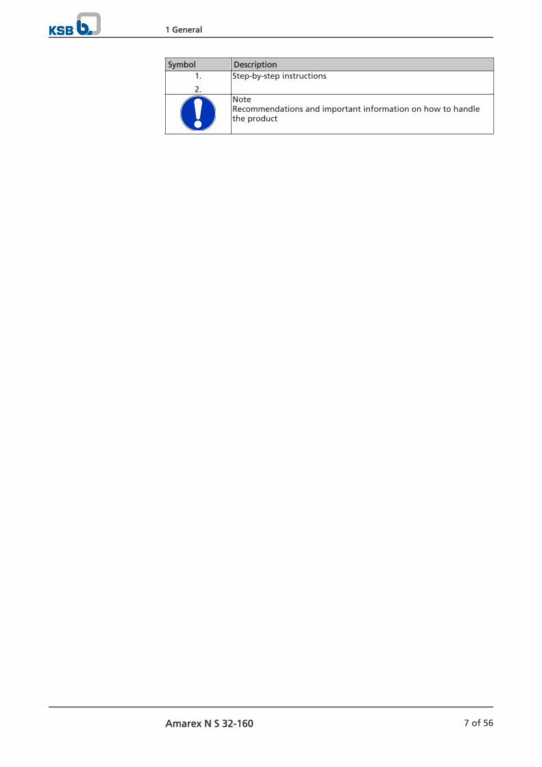
Symbol Description1.
2.
Step-by-step instructions
NoteRecommendations and important information on how to handlethe product
1 General
Amarex N S 32-160 7 of 56
2 SafetyAll the information contained in this section refers to hazardous situations.
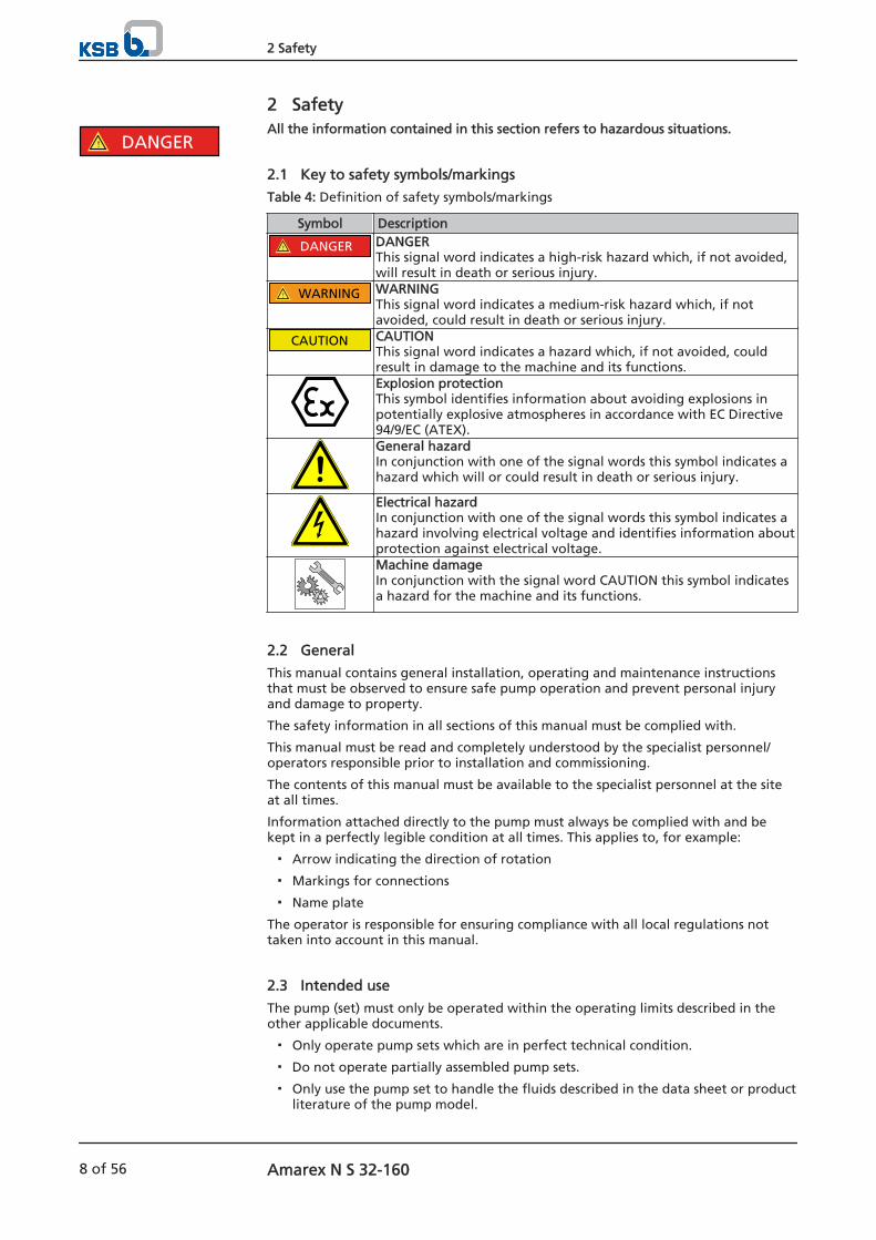
2.1 Key to safety symbols/markings
Table 4: Definition of safety symbols/markings
Symbol Description
! DANGER DANGERThis signal word indicates a high-risk hazard which, if not avoided,will result in death or serious injury.
! WARNING WARNINGThis signal word indicates a medium-risk hazard which, if notavoided, could result in death or serious injury.
CAUTION CAUTIONThis signal word indicates a hazard which, if not avoided, couldresult in damage to the machine and its functions.Explosion protectionThis symbol identifies information about avoiding explosions inpotentially explosive atmospheres in accordance with EC Directive94/9/EC (ATEX).General hazardIn conjunction with one of the signal words this symbol indicates ahazard which will or could result in death or serious injury.
Electrical hazardIn conjunction with one of the signal words this symbol indicates ahazard involving electrical voltage and identifies information aboutprotection against electrical voltage.Machine damage In conjunction with the signal word CAUTION this symbol indicatesa hazard for the machine and its functions.
2.2 General
This manual contains general installation, operating and maintenance instructionsthat must be observed to ensure safe pump operation and prevent personal injuryand damage to property.
The safety information in all sections of this manual must be complied with.
This manual must be read and completely understood by the specialist personnel/operators responsible prior to installation and commissioning.
The contents of this manual must be available to the specialist personnel at the siteat all times.
Information attached directly to the pump must always be complied with and bekept in a perfectly legible condition at all times. This applies to, for example:
Arrow indicating the direction of rotation
Markings for connections
Name plate
The operator is responsible for ensuring compliance with all local regulations nottaken into account in this manual.
2.3 Intended use
The pump (set) must only be operated within the operating limits described in theother applicable documents.
Only operate pump sets which are in perfect technical condition.
Do not operate partially assembled pump sets.
Only use the pump set to handle the fluids described in the data sheet or productliterature of the pump model.
! DANGER
2 Safety
8 of 56 Amarex N S 32-160
Never operate the pump set without the fluid to be handled.
Observe the limits for continuous operation specified in the data sheet orproduct literature (Qmin
2) and Qmax3)) (to prevent damage such as shaft fracture,
bearing failure, mechanical seal damage, etc).
When untreated waste water is handled the duty points in continuous operationlie within 0.7 to 1.2 x Qopt
4) to minimise the risk of clogging/hardening.
Avoid duty points for continuous operation at very low speeds and small flowrates (<0.7 x Qopt
4)).
Observe the maximum flow rates indicated in the data sheet or productliterature (to prevent overheating, mechanical seal damage, cavitation damage,bearing damage, etc).
Do not throttle the flow rate on the suction side of the pump set (to preventcavitation damage).
Consult the manufacturer about any use or mode of operation not described inthe data sheet or product literature.
The pump set must only be used for the following applications:
Impeller with cutter (impeller type S)
Suitable for intermittent operationhandling the following fluids:Domestic waste waterRaw waterFaeces
Prevention of foreseeable misuse
Observe the minimum flow velocities required to fully open the swing checkvalves to prevent the reduction of pressure and risk of clogging.(Contact the manufacturer for the required minimum flow velocities/losscoefficients.)
Never exceed the permissible operating limits specified in the data sheet and inthe product literature regarding pressure, temperature, etc.
Observe all safety information and instructions in this manual.
2.4 Personnel qualification and training
All personnel involved must be fully qualified to transport, install, operate, maintainand inspect the machinery this manual refers to.
The responsibilities, competence and supervision of all personnel involved intransport, installation, operation, maintenance and inspection must be clearlydefined by the operator.
Deficits in knowledge must be rectified by means of training and instructionprovided by sufficiently trained specialist personnel. If required, the operator cancommission the manufacturer/supplier to train the personnel.
Training on the pump (set) must always be supervised by technical specialistpersonnel.
2.5 Consequences and risks caused by non-compliance with these operatinginstructions
Non-compliance with these operating instructions will lead to forfeiture ofwarranty cover and of any and all rights to claims for damages.
Non-compliance can, for example, have the following consequences:
2) Minimum permissible flow rate3) Maximum permissible flow rate4) Best efficiency point
2 Safety
Amarex N S 32-160 9 of 56
– Hazards to persons due to electrical, thermal, mechanical and chemicaleffects and explosions
– Failure of important product functions
– Failure of prescribed maintenance and servicing practices
– Hazard to the environment due to leakage of hazardous substances
2.6 Safety awareness
In addition to the safety information contained in this manual and the intended use,the following safety regulations shall be complied with:
Accident prevention, health and safety regulations
Explosion protection regulations
Safety regulations for handling hazardous substances
Applicable standards and laws
2.7 Safety information for the user/operator
Provide the personnel with protective equipment and make sure it is used.
Contain leakages (e.g. at the shaft seal) of hazardous fluids handled (e.g.explosive, toxic, hot) so as to avoid any danger to persons and the environment.Adhere to all relevant laws.
Eliminate all electrical hazards. (In this respect refer to the applicable nationalsafety regulations and/or regulations issued by the local energy supplycompanies.)
If shutting down the pump does not increase potential risk, fit an emergency-stop control device in the immediate vicinity of the pump (set) during pump setinstallation.
2.8 Safety information for maintenance, inspection and installation work
Modifications or alterations of the pump are only permitted with themanufacturer's prior consent.
Use only original spare parts or parts authorised by the manufacturer. The use ofother parts can invalidate any liability of the manufacturer for resulting damage.
The operator ensures that all maintenance, inspection and installation work isperformed by authorised, qualified specialist personnel who are thoroughlyfamiliar with the manual.
Only carry out work on the pump (set) during standstill of the pump.
The pump casing must have cooled down to ambient temperature.
Pump pressure must have been released and the pump must have been drained.
When taking the pump set out of service always adhere to the proceduredescribed in the manual. ( Section 6.3 Page 34)
Decontaminate pumps which handle fluids posing a health hazard.
As soon as the work is completed, re-install and/or re-activate any safety-relevantand protective devices. Before returning the product to service, observe allinstructions on commissioning. ( Section 6.1 Page 32)
2.9 Unauthorised modes of operation
Never operate the pump (set) outside the limits stated in the data sheet and in thismanual.
The warranty relating to the operating reliability and safety of the supplied pump(set) is only valid if the equipment is used in accordance with its intended use.
2 Safety
10 of 56 Amarex N S 32-160
2.10 Explosion protection
Always observe the information on explosion protection given in this section whenoperating an explosion-proof pump set.
Sections of the manual marked by the Ex symbol apply to explosion-proof pump setsalso when temporarily operated outside potentially explosive atmospheres.Only pumps/pump sets marked as explosion-proof and identified as such in the datasheet must be used in potentially explosive atmospheres.
Special conditions apply to the operation of explosion-proof pump sets in accordancewith EC Directive 94/9/EC (ATEX). Especially adhere to the sections in this manual marked with the Ex symbol. The explosion-proof status of the pump set is only assured if the pump set is used inaccordance with its intended use. Never operate the pump (set) outside the limits stated in the data sheet and on thename plate.Prevent impermissible modes of operation at all times.
2.10.1 Repair
Special regulations apply to repair work on explosion-proof pumps. Modifications oralteration of the pump set could affect explosion protection and are only permittedafter consultation with the manufacturer.
Repair work at the flameproof joints must only be performed in accordance with themanufacturer's instructions. Repair to the values in tables 1 and 2 of EN 60079-1 isnot permitted.
! DANGER
2 Safety
Amarex N S 32-160 11 of 56

3 Transport/Temporary Storage/Disposal
3.1 Checking the condition upon delivery
1. On transfer of goods, check each packaging unit for damage.
2. In the event of in-transit damage, assess the exact damage, document it andnotify KSB or the supplying dealer (as applicable) and the insurer about thedamage in writing immediately.
3.2 Transport
DANGER
Improper transportDanger to life from falling parts!Damage to the pump set!
▷ Use the attachment point provided (pump handle) for attaching liftingaccessories.
▷ Never suspend the pump set by its power cable.
▷ Use the lifting chain/rope included in the scope of supply exclusively forlowering/lifting the pump set into/out of the pump sump.
▷ Securely attach the lifting chain/rope to the pump and crane.
▷ Use tested, marked and approved lifting accessories only.
▷ Observe any regional transport regulations.
▷ Observe the product literature supplied by the lifting accessory manufacturer.
▷ The load-carrying capacity of the lifting accessory must be higher than theweight indicated on the name plate of the pump set to be lifted. Take intoaccount any additional system components to be lifted.
3.3 Storage/Preservation
If commissioning is to take place some time after delivery, we recommend that thefollowing measures be taken for pump set storage:
CAUTIONImproper storageDamage to the power cables!
▷ Support the power cables at the cable entry to prevent permanentdeformation.
▷ Only remove the protective caps from the power cables at the time ofinstallation.
CAUTIONDamage during storage by humidity, dirt, or verminCorrosion/contamination of the pump (set)!
▷ For outdoor storage cover the packed or unpacked pump (set) and accessorieswith waterproof material.
CAUTIONWet, contaminated or damaged openings and connectionsLeakage or damage to the pump set!
▷ Only remove caps/covers from the openings of the pump set at the time ofinstallation.
3 Transport/Temporary Storage/Disposal
12 of 56 Amarex N S 32-160
Table 5: Ambient conditions for storage
Ambient conditions ValueRelative humidity 5 % to 85 %
(non-condensing)Ambient temperature - 20 to + 70°C
Store the pump set under dry and vibration-free conditions, if possible in itsoriginal packaging.
1. Spray-coat the inside wall of the pump casing, and in particular the impellerclearance areas, with a preservative.
2. Spray the preservative through the suction and discharge nozzles.It is advisable to then close the pump nozzles (e.g. with plastic caps or similar).
NOTEObserve the manufacturer's instructions for application/removal of the preservative.
3.4 Return to supplier
1. Drain the pump as per operating instructions. ( Section 7.3 Page 40)2. Always flush and clean the pump, particularly if it has been used for handling
noxious, explosive, hot or other hazardous fluids.
3. If the fluids handled by the pump (set) leave residues which might lead tocorrosion when coming into contact with atmospheric humidity, or which mightignite when coming into contact with oxygen, the pump set must beneutralised, and anhydrous inert gas must be blown through the pump fordrying purposes.
4. Always complete and enclose a certificate of decontamination when returningthe pump (set).Always indicate any safety and decontamination measures taken.
NOTEIf required, a blank certificate of decontamination can be downloaded from theKSB web site at: www.ksb.com/certificate_of_decontamination
3.5 Disposal
WARNINGFluids, consumables and supplies which are hot or pose a health hazardHazard to persons and the environment!
▷ Collect and properly dispose of flushing fluid and any residues of the fluidhandled.
▷ Wear safety clothing and a protective mask, if required.
▷ Observe all legal regulations on the disposal of fluids posing a health hazard.
1. Dismantle the pump (set).Collect greases and other lubricants during dismantling.
2. Separate and sort the pump materials, e.g. by:- Metals- Plastics- Electronic waste- Greases and other lubricants
3. Dispose of materials in accordance with local regulations or in anothercontrolled manner.
3 Transport/Temporary Storage/Disposal
Amarex N S 32-160 13 of 56
4 Description of the Pump (Set)
4.1 General description
Explosion-proof pump for handling domestic waste water, raw water and faeces inintermittent operation.
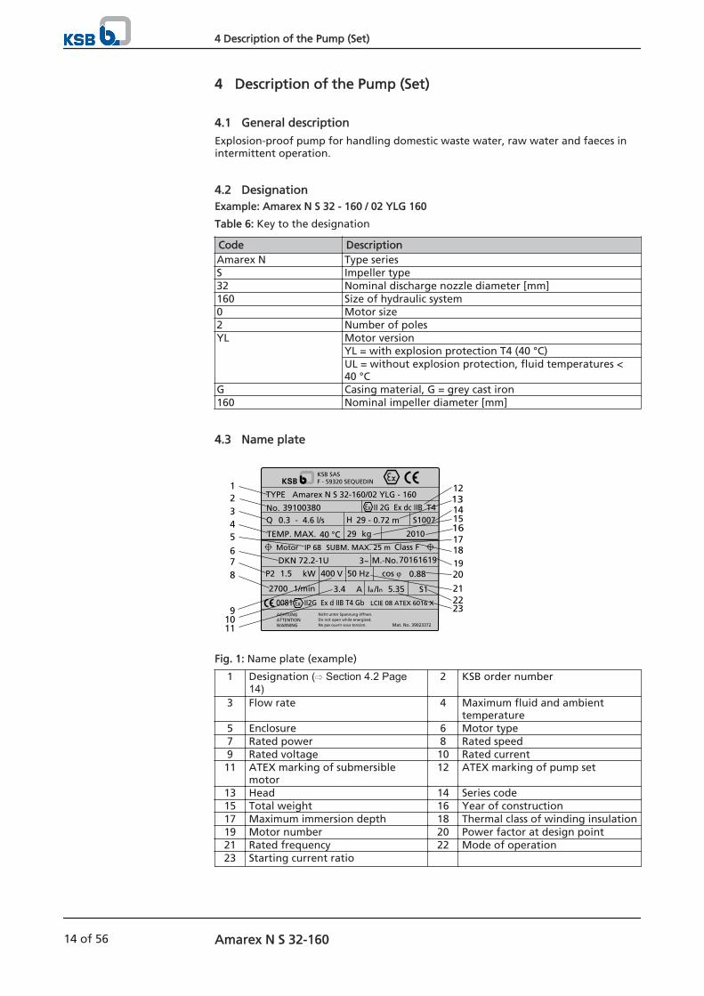
4.2 DesignationExample: Amarex N S 32 - 160 / 02 YLG 160
Table 6: Key to the designation
Code DescriptionAmarex N Type seriesS Impeller type32 Nominal discharge nozzle diameter [mm]160 Size of hydraulic system0 Motor size2 Number of polesYL Motor version
YL = with explosion protection T4 (40 °C)UL = without explosion protection, fluid temperatures <40 °C
G Casing material, G = grey cast iron160 Nominal impeller diameter [mm]
4.3 Name plate
391003800.3 - 4.6 l/s
TEMP. MAX. 40 °C
1.5
2700
400
3.4 5.35
29
0.8850 Hz
29 - 0.72 m
70161619DKN 72.2-1U
Amarex N S 32-160/02 YLG - 160
Nicht unter Spannung öffnen.Do not open while energised.Ne pas ouvrir sous tension.
ACHTUNGATTENTIONWARNING Mat. No. 39023372
TYPE
No.S1007
2010
Q
3~
Motor
P2 kW
1/min
V
A
IP 68 SUBM. MAX. 25 m
S1Ia /In
kg
H
M.-No.
cos φ
KSB SASF - 59320 SEQUEDIN
0081 II2G Ex d IIB T4 Gb
II 2G Ex dc IIB T4
LCIE 08 ATEX 6016 X
Class F
21
345
6
91011
13
16
1817
1415
20
21
23
7
12
22
819
Fig. 1: Name plate (example)
1 Designation ( Section 4.2 Page14)
2 KSB order number
3 Flow rate 4 Maximum fluid and ambienttemperature
5 Enclosure 6 Motor type7 Rated power 8 Rated speed9 Rated voltage 10 Rated current
11 ATEX marking of submersiblemotor
12 ATEX marking of pump set
13 Head 14 Series code15 Total weight 16 Year of construction17 Maximum immersion depth 18 Thermal class of winding insulation19 Motor number 20 Power factor at design point21 Rated frequency 22 Mode of operation23 Starting current ratio
4 Description of the Pump (Set)
14 of 56 Amarex N S 32-160
4.4 Design detailsDesign
Fully floodable submersible motor pump
Not self-priming
Close-coupled pump set
Shaft seal
Pump end: one bi-directional mechanical seal with liquid reservoirDrive end: one shaft seal ring
Impeller type
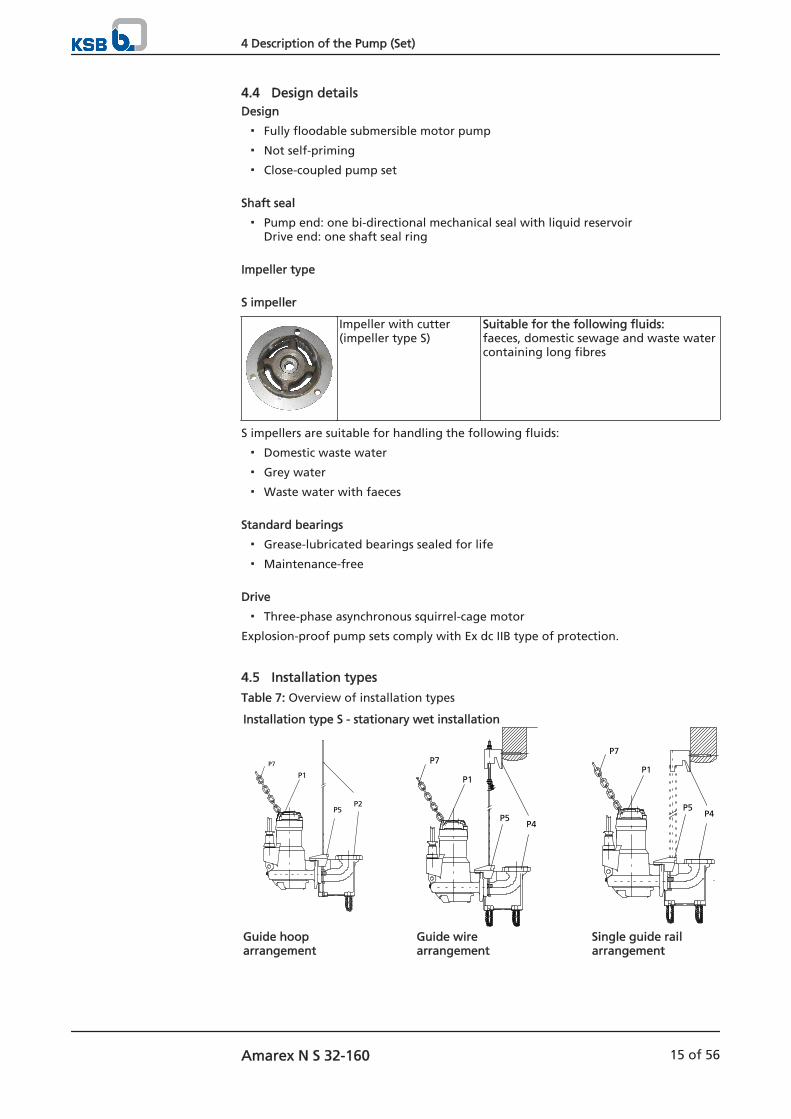
S impeller
Impeller with cutter (impeller type S)
Suitable for the following fluids:faeces, domestic sewage and waste watercontaining long fibres
S impellers are suitable for handling the following fluids:
Domestic waste water
Grey water
Waste water with faeces
Standard bearings
Grease-lubricated bearings sealed for life
Maintenance-free
Drive
Three-phase asynchronous squirrel-cage motor
Explosion-proof pump sets comply with Ex dc IIB type of protection.
4.5 Installation types
Table 7: Overview of installation types
Installation type S - stationary wet installation
P1
P7
P5P2
P1
P7
P5P4
P1
P7
P5P4
Guide hooparrangement
Guide wirearrangement
Single guide railarrangement
4 Description of the Pump (Set)
Amarex N S 32-160 15 of 56
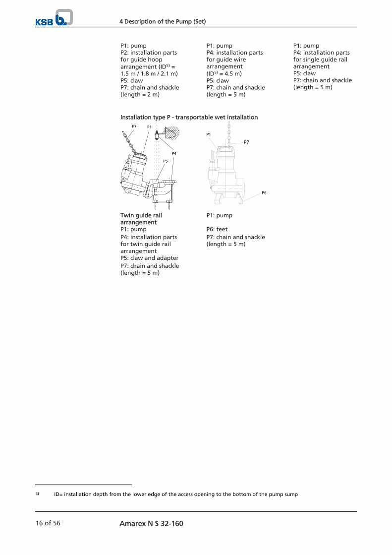
P1: pumpP2: installation partsfor guide hooparrangement (ID5) =1.5 m / 1.8 m / 2.1 m)P5: clawP7: chain and shackle (length = 2 m)
P1: pumpP4: installation partsfor guide wirearrangement(ID5) = 4.5 m)P5: clawP7: chain and shackle (length = 5 m)
P1: pumpP4: installation partsfor single guide railarrangementP5: clawP7: chain and shackle (length = 5 m)
Installation type P - transportable wet installation
P1P7
P5
P4
P1
P6
P7
Twin guide railarrangement
P1: pump
P1: pump P6: feet P4: installation partsfor twin guide railarrangement
P7: chain and shackle (length = 5 m)
P5: claw and adapter P7: chain and shackle (length = 5 m)
5) ID= installation depth from the lower edge of the access opening to the bottom of the pump sump
4 Description of the Pump (Set)
16 of 56 Amarex N S 32-160
4.6 Configuration and function
1
2
3
45
6
7
9
8
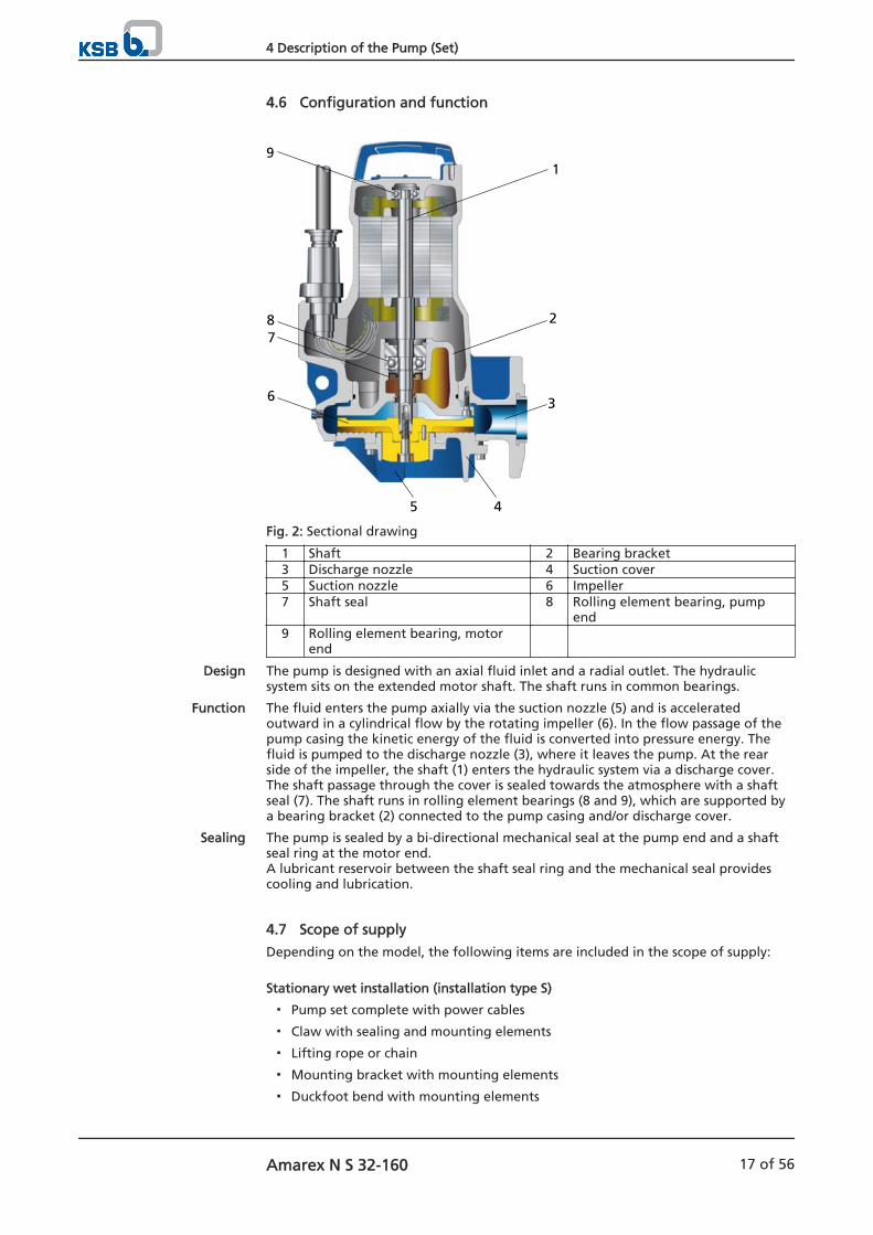
Fig. 2: Sectional drawing
1 Shaft 2 Bearing bracket3 Discharge nozzle 4 Suction cover5 Suction nozzle 6 Impeller7 Shaft seal 8 Rolling element bearing, pump
end9 Rolling element bearing, motor
end
The pump is designed with an axial fluid inlet and a radial outlet. The hydraulicsystem sits on the extended motor shaft. The shaft runs in common bearings.
The fluid enters the pump axially via the suction nozzle (5) and is acceleratedoutward in a cylindrical flow by the rotating impeller (6). In the flow passage of thepump casing the kinetic energy of the fluid is converted into pressure energy. Thefluid is pumped to the discharge nozzle (3), where it leaves the pump. At the rearside of the impeller, the shaft (1) enters the hydraulic system via a discharge cover.The shaft passage through the cover is sealed towards the atmosphere with a shaftseal (7). The shaft runs in rolling element bearings (8 and 9), which are supported bya bearing bracket (2) connected to the pump casing and/or discharge cover.
The pump is sealed by a bi-directional mechanical seal at the pump end and a shaftseal ring at the motor end.A lubricant reservoir between the shaft seal ring and the mechanical seal providescooling and lubrication.
4.7 Scope of supply
Depending on the model, the following items are included in the scope of supply:
Stationary wet installation (installation type S)
Pump set complete with power cables
Claw with sealing and mounting elements
Lifting rope or chain
Mounting bracket with mounting elements
Duckfoot bend with mounting elements
Design
Function
Sealing
4 Description of the Pump (Set)
Amarex N S 32-160 17 of 56

Guiding equipment(guide rails are not included in KSB's scope of supply)
Transportable wet-installed model (installation type P)
Pump set complete with power cables
3 feet, or 3 feet and a pump stool, with fastening elements
Lifting rope or chain
NOTEA separate name plate is included in KSB's scope of supply.This name plate must be attached in a clearly visible position outside the place ofinstallation, e.g. at the control panel, pipeline or mounting bracket.
4.8 Dimensions and weights
For dimensions and weights please refer to the general arrangement drawing/outlinedrawing or data sheet of the pump set.
4 Description of the Pump (Set)
18 of 56 Amarex N S 32-160

5 Installation at Site
5.1 Safety regulations
DANGER
Improper installation in potentially explosive atmospheresExplosion hazard!Damage to the pump set!
▷ Comply with the applicable local explosion protection regulations.
▷ Observe the information given in the data sheet and on the name plate of thepump set.
DANGER
Persons in the tank during pump operationElectric shock!
▷ Never start up the pump set when there are persons in the tank.
WARNINGImpermissible solid objects (tools, screws/bolts or similar) in the pump sump/inlettank during pump start-upPersonal injury and damage to property!
▷ Check the pump sump/inlet tank for impermissible solid objects beforeflooding, and remove, if necessary.
5.2 Checks to be carried out prior to installation
5.2.1 Preparing the place of installation
Place of installation for stationary models
WARNINGInstallation on mounting surfaces which are unsecured and cannot support the loadPersonal injury and damage to property!
▷ Ensure the concrete's compressive strength is sufficient (in accordance withC35/45 in exposure class XC1 to EN 206-1).
▷ The mounting surface must have set and must be completely horizontal andeven.
▷ Observe the weights indicated.
Any resonances at the usual excitation frequencies (1 x and 2 x rotational frequency,rotational noise) must be prevented both in the foundation and in the connectedpiping, as such frequencies may cause extreme vibrations.
1. Check the structural requirements. All structural work required must have been prepared in accordance with thedimensions stated in the outline drawing/general arrangement drawing.
Resonances
5 Installation at Site
Amarex N S 32-160 19 of 56
Place of installation for transportable models
WARNINGIncorrect positioningPersonal injury and damage to property!
▷ Set the pump set down in a vertical position with the motor on top.
▷ Use appropriate means to secure the pump set against overturning and tippingover.
▷ Refer to the weights given in the data sheet/on the name plate.
Any resonances at the usual excitation frequencies (1 x and 2 x rotational frequency,rotational noise) must be prevented both in the foundation and in the connectedpiping, as such frequencies may cause extreme vibrations.
1. Check the structural requirements. All structural work required must have been prepared in accordance with thedimensions stated in the outline drawing/general arrangement drawing.
5.2.2 Checking the direction of rotation
DANGER
Pump set running dryExplosion hazard!
▷ Check the direction of rotation of explosion-proof pump sets outside thepotentially explosive atmosphere.
DANGER
Pump set running dryExplosion hazard!
▷ Never allow an explosion-proof pump set to run dry!
WARNINGHands or objects inside the pump casingRisk of injuries, damage to the pump!
▷ Never put your hands or any other objects into the pump.
▷ Make sure that there is no foreign matter inside the pump.
▷ Do not hold the pump while checking the direction of rotation.
The pump set is connected to the power supply.
1. Start the pump set and stop it again immediately to determine the motor'sdirection of rotation.
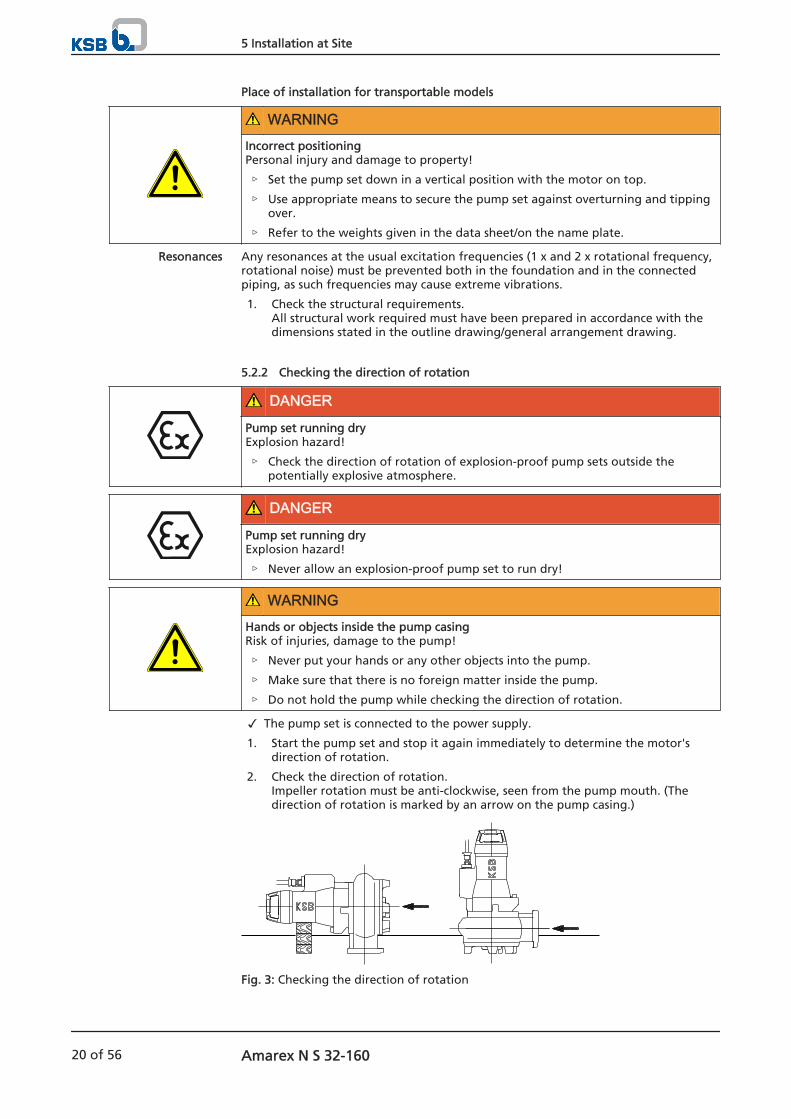
2. Check the direction of rotation. Impeller rotation must be anti-clockwise, seen from the pump mouth. (Thedirection of rotation is marked by an arrow on the pump casing.)
Fig. 3: Checking the direction of rotation
Resonances
5 Installation at Site
20 of 56 Amarex N S 32-160
3. If the impeller is running in the wrong direction of rotation, check the electricalconnection of the pump in the control system.
4. Disconnect the pump set from the power supply and make sure it cannot beswitched on unintentionally.
5.3 Installing the pump set
Always observe the general arrangement drawing/outline drawing when installingthe pump set.
5.3.1 Stationary wet installation
5.3.1.1 Fastening the duckfoot bend
Depending on the pump size, the duckfoot bend is either fastened with chemicalanchors and/or foundation rails.
Fastening the duckfoot bend with chemical anchors
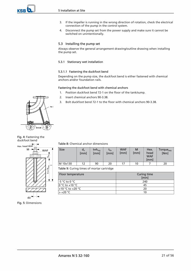
1. Position duckfoot bend 72-1 on the floor of the tank/sump.
2. Insert chemical anchors 90-3.38.
3. Bolt duckfoot bend 72-1 to the floor with chemical anchors 90-3.38.
Table 8: Chemical anchor dimensions
Size do
[mm]t=hreq
[mm]tfix
[mm]WAF[mm]
M[mm]
Hex.headWAF[mm]
Torqueassy
[Nm]
M 10x130 12 90 20 17 10 7 20
Table 9: Curing times of mortar cartridge
Floor temperature Curing time[min]
-5 °C to 0 °C 2400 °C to +10 °C 45+10 °C to +20 °C 20> +20 °C 10
Fig. 4: Fastening theduckfoot bend
t=
hre
qt f
ix
WAFMHex. head WAF
do
l
Fig. 5: Dimensions
5 Installation at Site
Amarex N S 32-160 21 of 56
5.3.1.2 Connecting the piping
DANGER
Impermissible loads acting on the flange of the duckfoot bendDanger to life from leakage of hot, toxic, corrosive or flammable fluids!
▷ Do not use the pump as an anchorage point for the piping.
▷ Anchor the pipelines in close proximity to the pump and connect them withouttransmitting any stresses or strains.
▷ Observe the permissible flange loads.
▷ Take appropriate measures to compensate thermal expansion of the piping.
NOTEWhen the pump set is used for draining low-level building areas, install a swingcheck valve in the discharge line to avoid backflow from the sewer system.
CAUTIONCritical speedIncreased vibrations!Damage to mechanical seals and bearings!
▷ Install a swing check valve in longer riser pipes to prevent the pump fromexcessive running in reverse.When fitting a swing check valve, make sure that the unit can still be ventedproperly.
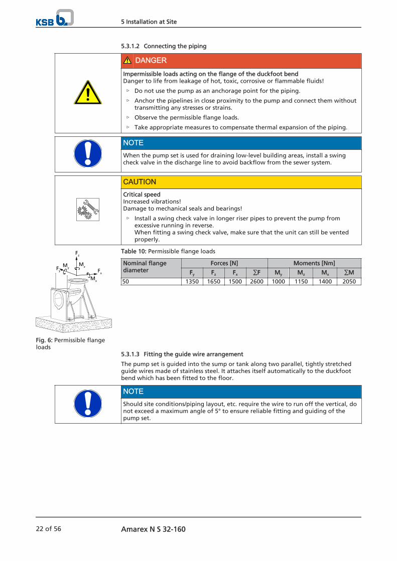
Table 10: Permissible flange loads
Nominal flangediameter
Forces [N] Moments [Nm]
Fy Fz Fx ∑F My Mz Mx ∑M
50 1350 1650 1500 2600 1000 1150 1400 2050
5.3.1.3 Fitting the guide wire arrangement
The pump set is guided into the sump or tank along two parallel, tightly stretchedguide wires made of stainless steel. It attaches itself automatically to the duckfootbend which has been fitted to the floor.
NOTEShould site conditions/piping layout, etc. require the wire to run off the vertical, donot exceed a maximum angle of 5° to ensure reliable fitting and guiding of thepump set.
Fx
Fz
Fy
MyMz
Mx
Fig. 6: Permissible flangeloads
5 Installation at Site
22 of 56 Amarex N S 32-160
Fitting the mounting bracket
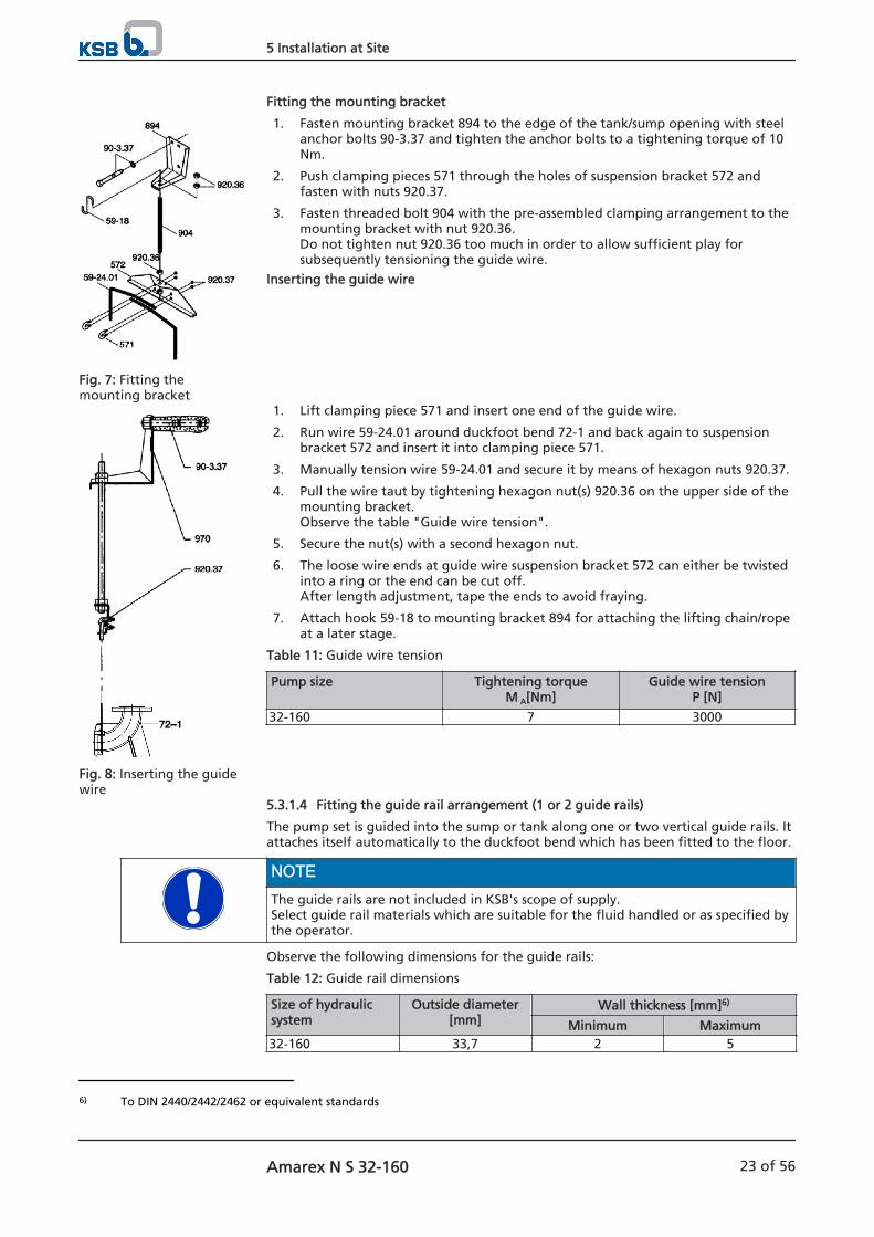
1. Fasten mounting bracket 894 to the edge of the tank/sump opening with steelanchor bolts 90-3.37 and tighten the anchor bolts to a tightening torque of 10Nm.
2. Push clamping pieces 571 through the holes of suspension bracket 572 andfasten with nuts 920.37.
3. Fasten threaded bolt 904 with the pre-assembled clamping arrangement to themounting bracket with nut 920.36.Do not tighten nut 920.36 too much in order to allow sufficient play forsubsequently tensioning the guide wire.
Inserting the guide wire
1. Lift clamping piece 571 and insert one end of the guide wire.
2. Run wire 59-24.01 around duckfoot bend 72-1 and back again to suspensionbracket 572 and insert it into clamping piece 571.
3. Manually tension wire 59-24.01 and secure it by means of hexagon nuts 920.37.
4. Pull the wire taut by tightening hexagon nut(s) 920.36 on the upper side of themounting bracket.Observe the table "Guide wire tension".
5. Secure the nut(s) with a second hexagon nut.
6. The loose wire ends at guide wire suspension bracket 572 can either be twistedinto a ring or the end can be cut off. After length adjustment, tape the ends to avoid fraying.
7. Attach hook 59-18 to mounting bracket 894 for attaching the lifting chain/ropeat a later stage.
Table 11: Guide wire tension
Pump size Tightening torqueM A[Nm]
Guide wire tensionP [N]
32-160 7 3000
5.3.1.4 Fitting the guide rail arrangement (1 or 2 guide rails)
The pump set is guided into the sump or tank along one or two vertical guide rails. Itattaches itself automatically to the duckfoot bend which has been fitted to the floor.
NOTEThe guide rails are not included in KSB's scope of supply.Select guide rail materials which are suitable for the fluid handled or as specified bythe operator.
Observe the following dimensions for the guide rails:
Table 12: Guide rail dimensions
Size of hydraulicsystem
Outside diameter[mm]
Wall thickness [mm]6)
Minimum Maximum32-160 33,7 2 5
Fig. 7: Fitting themounting bracket
Fig. 8: Inserting the guidewire
6) To DIN 2440/2442/2462 or equivalent standards
5 Installation at Site
Amarex N S 32-160 23 of 56

Fitting the mounting bracket
1. Fasten mounting bracket 894 to the edge of the sump opening with steelanchor bolts 90-3.37 and tighten the anchor bolts to a tightening torque of 10Nm.Observe the hole pattern for the anchor bolts. (See outline drawing.)
Fitting the guide rails (arrangement with 2 guide rails)
CAUTIONImproper installation of the guide railsDamage to the guide rail arrangement!
▷ Always adjust the guide rails so that they are in a perfectly vertical position.
NOTEFor installation depths > 6 m, the scope of supply may include brackets as a middlesupport for the guide rails. The mounting brackets also serve as spacers betweenthe two guide rails.
1. Position adapter 82.5 on duckfoot bend 72.1 and fasten it with screws 914.2,discs 550.02 and nuts 920.02.
2. Place rails 710 onto the conical bosses of adapter 82.5 and position themvertically.
3. Mark the length of rails 710 (up to the lower edge of the mounting bracket),taking into account the adjusting range of the slotted holes in mountingbracket 894.
4. Shorten rails 710 with a 90° cut to the pipe axis. Debur the rails inside andoutside.
5. Insert mounting bracket 894 with clamping sleeves 81.51 into guide rails 710until the mounting bracket rests on the rail ends.
6. Tighten nuts 920.01. This expands the clamping sleeves so that they clamp the rails at the inside raildiameter.
7. Secure nut 920.01 with a second nut.
Fitting the guide rails (single guide rail arrangement)
1. Position rail 710 in the recess of duckfoot bend 72.1. Place the rail in a verticalposition.
2. Mark the length of rail 710 (up to the lower edge of the mounting bracket),taking into account the adjusting range of the slotted holes in mountingbracket 894.
3. Shorten rail 710 with a 90° cut to the pipe axis. Debur the rail inside andoutside.
4. Insert mounting bracket 894 into guide rail 710 until the mounting bracket restson the rail end.
90-3.37
894
Fig. 9: Fitting themounting bracket
920.0181.51
894
710
914.02
550.01
914.01
82.5
550.02
920.02
Fig. 10: Fitting 2 guiderails
710
894
60.3
33.7
UG1273704
Fig. 11: Fitting a singleguide rail
5 Installation at Site
24 of 56 Amarex N S 32-160
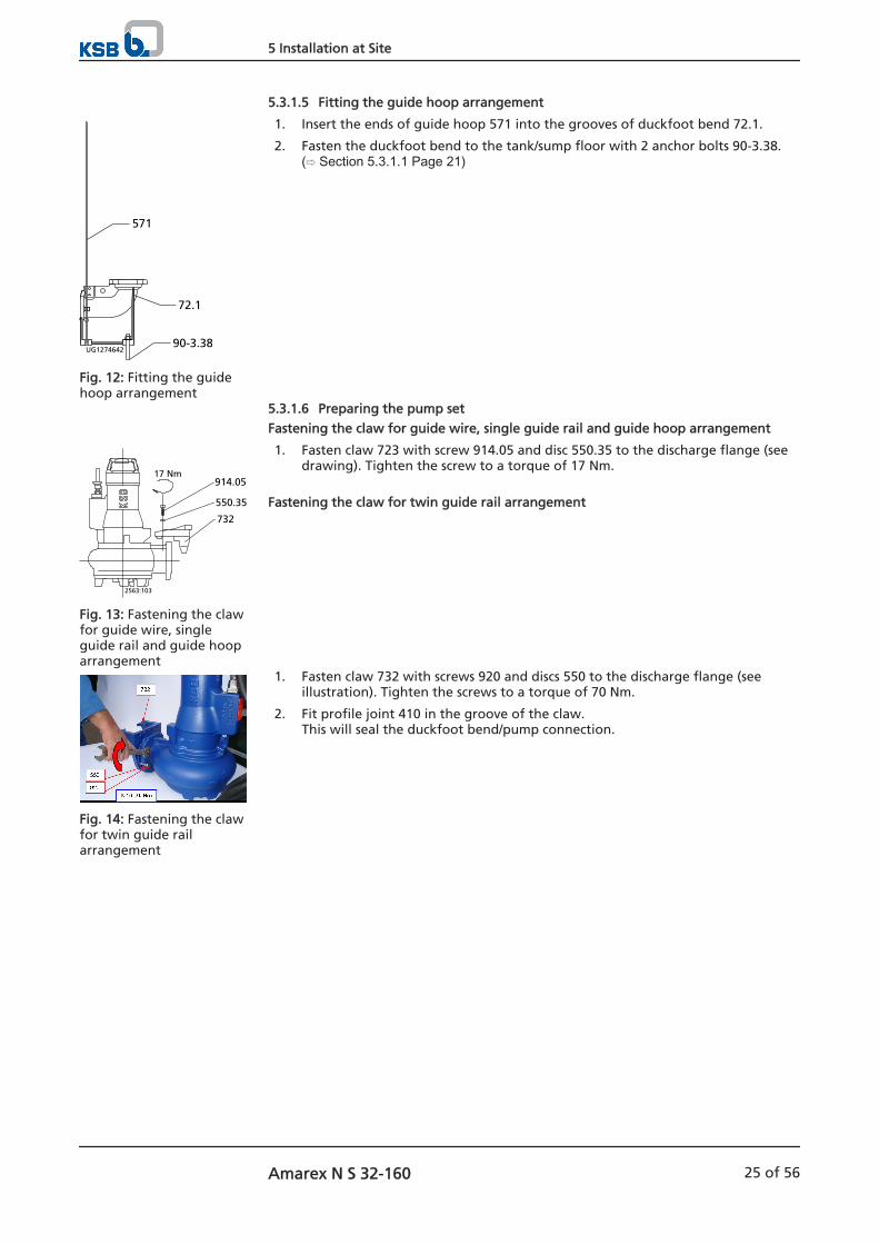
5.3.1.5 Fitting the guide hoop arrangement
1. Insert the ends of guide hoop 571 into the grooves of duckfoot bend 72.1.
2. Fasten the duckfoot bend to the tank/sump floor with 2 anchor bolts 90-3.38.( Section 5.3.1.1 Page 21)
5.3.1.6 Preparing the pump set
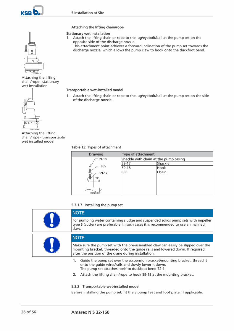
Fastening the claw for guide wire, single guide rail and guide hoop arrangement
1. Fasten claw 723 with screw 914.05 and disc 550.35 to the discharge flange (seedrawing). Tighten the screw to a torque of 17 Nm.
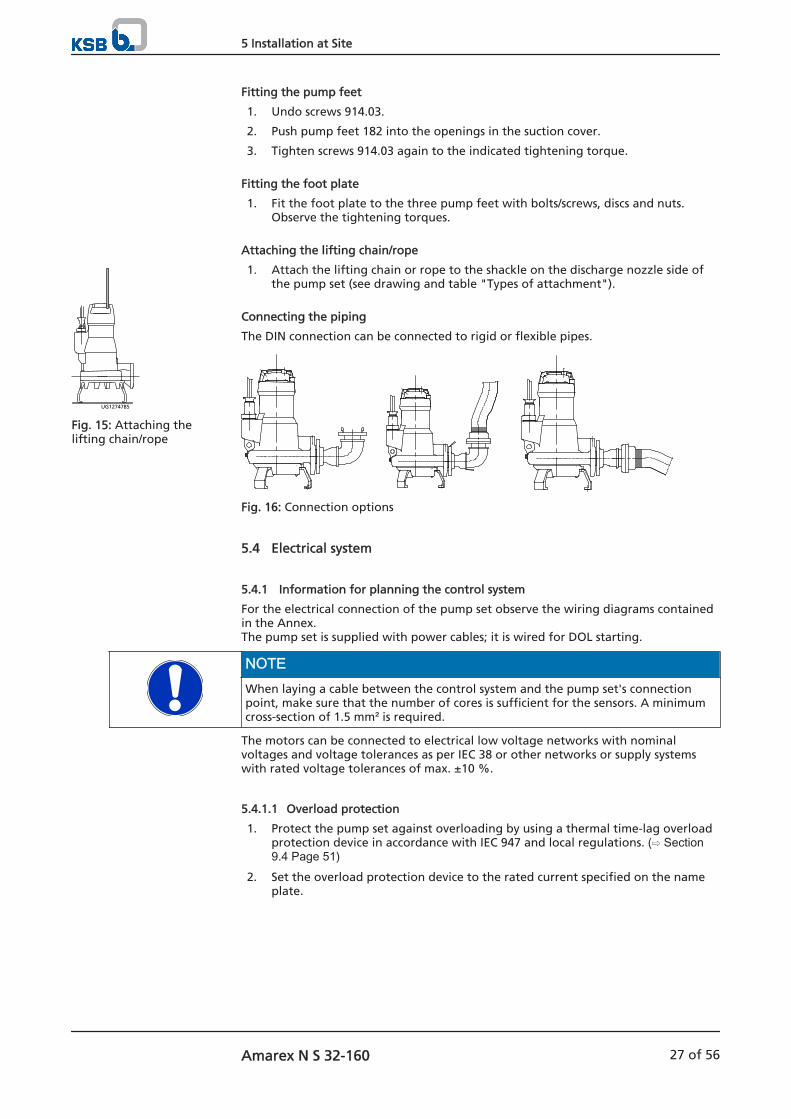
Fastening the claw for twin guide rail arrangement
1. Fasten claw 732 with screws 920 and discs 550 to the discharge flange (seeillustration). Tighten the screws to a torque of 70 Nm.
2. Fit profile joint 410 in the groove of the claw. This will seal the duckfoot bend/pump connection.
571
UG1274642
72.1
90-3.38
Fig. 12: Fitting the guidehoop arrangement
2563:103
732
550.35
914.0517 Nm
Fig. 13: Fastening the clawfor guide wire, singleguide rail and guide hooparrangement
Fig. 14: Fastening the clawfor twin guide railarrangement
5 Installation at Site
Amarex N S 32-160 25 of 56
Attaching the lifting chain/rope
UG1274774
Attaching the liftingchain/rope - stationarywet installation
Stationary wet installation1. Attach the lifting chain or rope to the lug/eyebolt/bail at the pump set on the
opposite side of the discharge nozzle.This attachment point achieves a forward inclination of the pump set towards thedischarge nozzle, which allows the pump claw to hook onto the duckfoot bend.
UG1274785
Attaching the liftingchain/rope - transportablewet installed model
Transportable wet-installed model
1. Attach the lifting chain or rope to the lug/eyebolt/bail at the pump set on the sideof the discharge nozzle.
Table 13: Types of attachment
Drawing Type of attachment59-18
885
59-17
UG1274869
Shackle with chain at the pump casing59-17 Shackle59-18 Hook885 Chain
5.3.1.7 Installing the pump set
NOTEFor pumping water containing sludge and suspended solids pump sets with impellertype S (cutter) are preferable. In such cases it is recommended to use an inclinedclaw.
NOTEMake sure the pump set with the pre-assembled claw can easily be slipped over themounting bracket, threaded onto the guide rails and lowered down. If required,alter the position of the crane during installation.
1. Guide the pump set over the suspension bracket/mounting bracket, thread itonto the guide wires/rails and slowly lower it down.The pump set attaches itself to duckfoot bend 72-1.
2. Attach the lifting chain/rope to hook 59-18 at the mounting bracket.
5.3.2 Transportable wet-installed model
Before installing the pump set, fit the 3 pump feet and foot plate, if applicable.
5 Installation at Site
26 of 56 Amarex N S 32-160
Fitting the pump feet
1. Undo screws 914.03.
2. Push pump feet 182 into the openings in the suction cover.
3. Tighten screws 914.03 again to the indicated tightening torque.
Fitting the foot plate
1. Fit the foot plate to the three pump feet with bolts/screws, discs and nuts.Observe the tightening torques.
Attaching the lifting chain/rope
1. Attach the lifting chain or rope to the shackle on the discharge nozzle side ofthe pump set (see drawing and table "Types of attachment").
Connecting the piping
The DIN connection can be connected to rigid or flexible pipes.
Fig. 16: Connection options
5.4 Electrical system
5.4.1 Information for planning the control system
For the electrical connection of the pump set observe the wiring diagrams containedin the Annex.The pump set is supplied with power cables; it is wired for DOL starting.
NOTEWhen laying a cable between the control system and the pump set's connectionpoint, make sure that the number of cores is sufficient for the sensors. A minimumcross-section of 1.5 mm² is required.
The motors can be connected to electrical low voltage networks with nominalvoltages and voltage tolerances as per IEC 38 or other networks or supply systemswith rated voltage tolerances of max. ±10 %.
5.4.1.1 Overload protection
1. Protect the pump set against overloading by using a thermal time-lag overloadprotection device in accordance with IEC 947 and local regulations. ( Section9.4 Page 51)
2. Set the overload protection device to the rated current specified on the nameplate.
UG1274785
Fig. 15: Attaching thelifting chain/rope
5 Installation at Site
Amarex N S 32-160 27 of 56
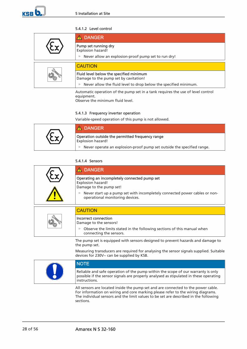
5.4.1.2 Level control
DANGER
Pump set running dryExplosion hazard!
▷ Never allow an explosion-proof pump set to run dry!
CAUTIONFluid level below the specified minimumDamage to the pump set by cavitation!
▷ Never allow the fluid level to drop below the specified minimum.
Automatic operation of the pump set in a tank requires the use of level controlequipment.Observe the minimum fluid level.
5.4.1.3 Frequency inverter operation
Variable-speed operation of this pump is not allowed.
DANGER
Operation outside the permitted frequency rangeExplosion hazard!
▷ Never operate an explosion-proof pump set outside the specified range.
5.4.1.4 Sensors
DANGER
Operating an incompletely connected pump setExplosion hazard!Damage to the pump set!
▷ Never start up a pump set with incompletely connected power cables or non-operational monitoring devices.
CAUTIONIncorrect connectionDamage to the sensors!
▷ Observe the limits stated in the following sections of this manual whenconnecting the sensors.
The pump set is equipped with sensors designed to prevent hazards and damage tothe pump set.
Measuring transducers are required for analysing the sensor signals supplied. Suitabledevices for 230V~ can be supplied by KSB.
NOTEReliable and safe operation of the pump within the scope of our warranty is onlypossible if the sensor signals are properly analysed as stipulated in these operatinginstructions.
All sensors are located inside the pump set and are connected to the power cable. For information on wiring and core marking please refer to the wiring diagrams.The individual sensors and the limit values to be set are described in the followingsections.
5 Installation at Site
28 of 56 Amarex N S 32-160
5.4.1.5 Motor temperature
DANGER
Insufficient cooling conditionsExplosion hazard!Winding damage!
▷ Never operate an explosion-proof pump set without operational temperaturemonitoring.
The Amarex N S 32-160 pump set features double monitoring of the windingtemperature. Two bimetal switches (terminals 20 and 21, max. 250 V~/2 A) serve astemperature control devices which open when the winding temperature is too high.
Tripping must result in the pump set cutting out. Automatic re-starting is permissible.
Two additional bimetal switches (terminals 21 and 22, max. 250 V~/2 A) serve astemperature limiters which open when the temperature limit is exceeded.
Tripping must result in the pump set cutting out. The pump set must not re-startautomatically.
5.4.2 Electrical connection
DANGER
Work on the pump set by unqualified personnelDanger of death from electric shock!
▷ Always have the electrical connections installed by a trained and qualifiedelectrician.
▷ Observe the IEC 60079 (DIN VDE 0100) regulation.
WARNINGIncorrect connection to the mainsDamage to the mains network, short circuit!
▷ Observe the technical specifications of the local energy supply companies.
▷ Inspect the power cable for visible damage.
▷ Never connect damaged power cables.
CAUTIONImproper routing of power cableDamage to the power cables!
▷ Never move the power cables at temperatures below - 25 .
▷ Never kink or crush the power cables.
▷ Never lift the pump set by the power cables.
▷ Adjust the length of the power cable to the site requirements.
CAUTIONMotor overloadDamage to the motor!
▷ Protect the motor by a thermal time-lag overload protection device inaccordance with IEC 947 and local regulations.
For electrical connection observe the wiring diagrams in the Annex and theinformation for planning the control system .
The pump set is supplied complete with power cable. Always connect all markedcores.
5 Installation at Site
Amarex N S 32-160 29 of 56
DANGER
Incorrect connectionExplosion hazard!
▷ The connection point of the cable ends must be located outside the potentiallyexplosive atmosphere or inside electrical equipment approved to equipmentcategory II2G.
DANGER
Operating an incompletely connected pump setExplosion hazard!Damage to the pump set!
▷ Never start up a pump set with incompletely connected power cables or non-operational monitoring devices.
DANGER
Connection of damaged power cablesDanger of death from electric shock!
▷ Check the power cables for damage before connecting them to the powersupply.
▷ Never connect damaged power cables.
CAUTIONFlow-induced motionDamage to the power cable!
▷ Run the power cable upwards without slack.
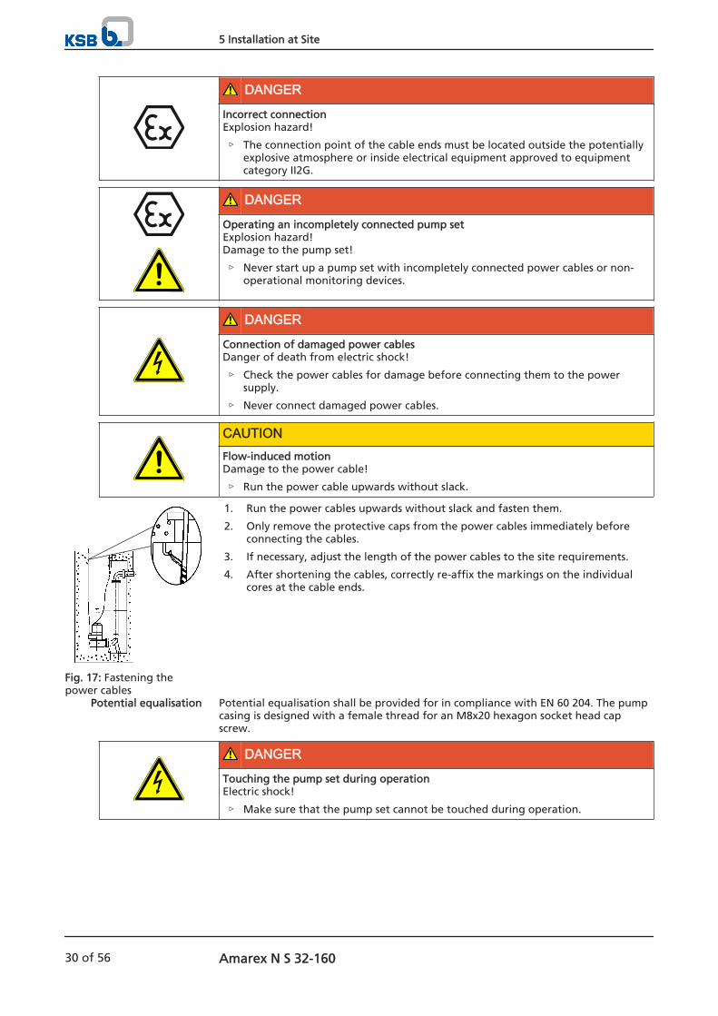
1. Run the power cables upwards without slack and fasten them.
2. Only remove the protective caps from the power cables immediately beforeconnecting the cables.
3. If necessary, adjust the length of the power cables to the site requirements.
4. After shortening the cables, correctly re-affix the markings on the individualcores at the cable ends.
Potential equalisation shall be provided for in compliance with EN 60 204. The pumpcasing is designed with a female thread for an M8x20 hexagon socket head capscrew.
DANGER
Touching the pump set during operationElectric shock!
▷ Make sure that the pump set cannot be touched during operation.
Fig. 17: Fastening thepower cables
Potential equalisation
5 Installation at Site
30 of 56 Amarex N S 32-160

DANGER
Chemically corrosive fluidsElectric shock!
▷ If the pump set is used in chemically corrosive fluids, never use the externalterminal for potential equalisation.
▷ Connect the potential equalisation conductor to a non-wetted flange of thedischarge line and establish an electric connection between the newly fittedpotential equalisation and the pump set.
5 Installation at Site
Amarex N S 32-160 31 of 56
6 Commissioning/Start-up/Shutdown
6.1 Commissioning/start-up
6.1.1 Prerequisites for commissioning/start-up
DANGER
Fluid level too lowExplosion hazard!Damage to the pump set!
▷ Completely prime the pump set with the fluid to be handled to reliably preventthe formation of a potentially explosive atmosphere.
▷ Always operate the pump set in such a way that air cannot ingress into thepump casing.
▷ Never allow the fluid level to drop below the specified minimum (R3).
▷ For continuous operation (S1) operate the pump in fully submerged condition.
DANGER
Persons in the tank during pump operationElectric shock!
▷ Never start up the pump set when there are persons in the tank.
Before commissioning/starting up the pump set, make sure that the followingconditions are met:
The pump set has been properly connected to the power supply and is equippedwith all protection devices.
The pump has been primed with the fluid to be pumped.
The direction of rotation has been checked.
After prolonged shutdown of the pump (set), the activities in ( Section 6.4 Page35) have been carried out.
6.1.2 Start-up
DANGER
Persons in the tank during pump operationElectric shock!
▷ Never start up the pump set when there are persons in the tank.
CAUTIONRe-starting while motor is still running downDamage to the pump set!
▷ Do not re-start the pump set before it has come to a standstill.
▷ Never start up the pump set while the pump is running in reverse.
The fluid level is sufficiently high.
CAUTIONPump start-up against a closed shut-off elementIncreased vibrations!Damage to mechanical seals and bearings!
▷ Never operate the pump set against a closed shut-off element.
1. Fully open the discharge line shut-off element, if any.
6 Commissioning/Start-up/Shutdown
32 of 56 Amarex N S 32-160
2. Start up the pump set.
6.2 Operating limits
DANGER
Non-compliance with operating limitsDamage to the pump set!
▷ Comply with the operating data indicated in the data sheet.
▷ Avoid operation against a closed shut-off element.
▷ Never operate an explosion-proof pump set at ambient and fluid temperaturesexceeding those specified in the data sheet or on the name plate.
▷ Never operate the pump set outside the limits specified below.
6.2.1 Frequency of starts
CAUTIONExcessive frequency of startsRisk of damage to the motor!
▷ Never exceed the specified frequency of starts.
To prevent high temperature increases in the motor, do not exceed the followingnumber of start-ups per hour.
Table 14: Frequency of starts
Interval Maximum frequency of starts[No. of starts]
Per hour 30Per year 5000
These values apply to mains start-up (DOL or with star-delta contactor,autotransformer, soft starter).
6.2.2 Supply voltage
DANGER
Non-compliance with permissible supply voltage tolerancesExplosion hazard!
▷ Never operate an explosion-proof pump (set) outside the specified range.
The maximum permissible deviation in supply voltage is ±10% of the rated voltage.The voltage difference between the individual phases must not exceed 1 %.
6.2.3 Fluid handled
6.2.3.1 Temperature of the fluid handled
The pump set is designed for transporting liquids. The pump set is not operationalunder freezing conditions.
CAUTIONDanger of frost/freezingDamage to the pump set!
▷ Drain the pump set or protect it against freezing.
6 Commissioning/Start-up/Shutdown
Amarex N S 32-160 33 of 56
Refer to the maximum permissible fluid and ambient temperature on the name plateand in the data sheet.
6.2.3.2 Minimum level of fluid handled
DANGER
Pump set running dryExplosion hazard!
▷ Never allow an explosion-proof pump set to run dry!
CAUTIONFluid level below the specified minimumDamage to the pump set by cavitation!
▷ Never allow the fluid level to drop below the specified minimum.
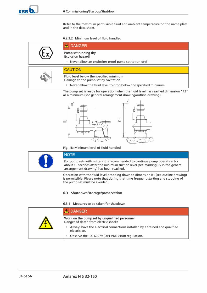
The pump set is ready for operation when the fluid level has reached dimension "R3"as a minimum (see general arrangement drawing/outline drawing).
Fig. 18: Minimum level of fluid handled
NOTEFor pump sets with cutters it is recommended to continue pump operation forabout 10 seconds after the minimum suction level (see marking RS in the generalarrangement drawing) has been reached.
Operation with the fluid level dropping down to dimension R1 (see outline drawing)is permissible. Please note that during that time frequent starting and stopping ofthe pump set must be avoided.
6.3 Shutdown/storage/preservation
6.3.1 Measures to be taken for shutdown
DANGER
Work on the pump set by unqualified personnelDanger of death from electric shock!
▷ Always have the electrical connections installed by a trained and qualifiedelectrician.
▷ Observe the IEC 60079 (DIN VDE 0100) regulation.
6 Commissioning/Start-up/Shutdown
34 of 56 Amarex N S 32-160
WARNINGUnintentional starting of pump setRisk of injury by moving parts!
▷ Make sure that the pump set cannot be started up unintentionally.
▷ Always make sure the electrical connections are disconnected before carryingout work on the pump set.
WARNINGFluids and supplies posing a health hazard and/or hot fluids or suppliesRisk of injury!
▷ Observe all relevant laws.
▷ When draining the fluid take appropriate measures to protect persons and theenvironment.
▷ Decontaminate pumps which handle fluids posing a health hazard.
CAUTIONDanger of frost/freezingDamage to the pump set!
▷ If there is any danger of frost/freezing, remove the pump set from the fluidhandled and clean, preserve and store it.
The pump set remains installed
Make sure sufficient fluid is available for the operation check run of the pumpset.
1. For prolonged shutdown periods, start up the pump set regularly between oncea month and once every three months for approximately one minute. This will prevent the formation of deposits within the pump and the pumpintake area.
The pump (set) is removed from the pipe and stored
All safety regulations are observed.
1. Clean the pump set.
2. Preserve the pump set.
3. Observe the instructions given in ( Section 3.3 Page 12) .
6.4 Returning to service
For returning the pump set to service observe the sections on commissioning/start-up( Section 6 Page 32) and operating limits. ( Section 6.2 Page 33)For returning the pump set to service after storage also follow the instructions forservicing/inspection.
WARNINGFailure to re-install or re-activate protective devicesRisk of personal injury from moving parts or escaping fluid!
▷ As soon as the work is complete, re-install and/or re-activate any safety-relevantand protective devices.
NOTEOn pumps/pump sets older than 5 years we recommend replacing all elastomerseals.
6 Commissioning/Start-up/Shutdown
Amarex N S 32-160 35 of 56

7 Servicing/Maintenance
7.1 Safety regulations
The operator ensures that all maintenance, inspection and installation work isperformed by authorised, qualified specialist personnel who are thoroughly familiarwith the manual.
DANGER
Sparks produced during servicing workExplosion hazard!
▷ Observe the safety regulations in force at the place of installation!
▷ Never open an energised pump set.
▷ After de-energising the pump set, allow at least 5 minutes before opening it.
▷ Always perform maintenance work on explosion-proof pump sets outsidepotentially explosive atmospheres only.
WARNINGUnintentional starting of pump setRisk of injury by moving parts!
▷ Make sure that the pump set cannot be started up unintentionally.
▷ Always make sure the electrical connections are disconnected before carryingout work on the pump set.
WARNINGFluids and supplies posing a health hazard and/or hot fluids or suppliesRisk of injury!
▷ Observe all relevant laws.
▷ When draining the fluid take appropriate measures to protect persons and theenvironment.
▷ Decontaminate pumps which handle fluids posing a health hazard.
WARNINGHot surfaceRisk of injury!
▷ Allow the pump set to cool down to ambient temperature.
WARNINGImproper lifting/moving of heavy assemblies or componentsPersonal injury and damage to property!
▷ Use suitable transport devices, lifting equipment and lifting tackle to moveheavy assemblies or components.
WARNINGInsufficient stabilityRisk of crushing hands and feet!
▷ During assembly/dismantling, secure the pump (set)/pump parts to preventtipping or falling over.
7 Servicing/Maintenance
36 of 56 Amarex N S 32-160

NOTESpecial regulations apply to repair work on explosion-proof pump sets.Modification or alteration of the pump set may affect explosion protection and areonly permitted after consultation with the manufacturer.
A regular maintenance schedule will help avoid expensive repairs and contribute totrouble-free, reliable operation of the pump (set) with a minimum of maintenanceexpenditure and work.
NOTEAll maintenance, service and installation work can be carried out by KSB Service orauthorised workshops. Find your contact in the attached "Addresses" booklet or onthe Internet at "www.ksb.com/contact".
Never use force when dismantling and reassembling the pump set.
7.2 Maintenance/inspection
Table 15: Overview of maintenance work
Maintenance interval Maintenance work For details see ...Every 4,000 operating hours7) Measure the insulation resistance ( Section 7.2.1.3 Page 38)
Check the power cables ( Section 7.2.1.2 Page 37)Visually inspect the lifting chain/rope ( Section 7.2.1.1 Page 37)Check the sensors Change the lubricantInspect the bearings
Every five years General overhaul
7.2.1 Inspection work
7.2.1.1 Checking the lifting chain/rope
The pump set has been lifted out of the pump sump and cleaned.
1. Inspect the lifting chain/rope as well as the attachment for any visible damage.
2. Replace any damaged components by original spare parts.
7.2.1.2 Checking the power cables
The pump set has been pulled out of the pump sump and cleaned.
1. Inspect the power cable for any visual damage.
2. Replace any damaged components by original spare parts.
The pump set has been pulled out of the pump sump and cleaned.
1. Measure the resistance between earth conductor and earth.The resistance measured must be less than 1 Ω.
2. Replace any damaged components by original spare parts.
DANGER
Defective earth conductorElectric shock!
▷ Never switch on a pump set with a defective earth conductor.
Visual inspection
Checking the earthconductor
7) At least once a year
7 Servicing/Maintenance
Amarex N S 32-160 37 of 56

7.2.1.3 Measuring the insulation resistance
Measure the insulation resistance of the motor winding during annual maintenancework.
The pump set has been disconnected in the control cabinet.
Use an insulation resistance measuring device.
The recommended measuring voltage equals 500 V (maximum permissible1000 V).
1. Measure the winding against earth.To do so, connect all winding ends together.
2. Measure the winding temperature sensors against earth.To do so, connect all core ends of the winding temperature sensors togetherand connect all winding ends to earth.
The insulation resistance of the core ends against earth must not be lower than1 MΩ.If the resistance measured is lower, power cable and motor resistance must bemeasured separately. Disconnect the power cable from the motor for thispurpose.
NOTEIf the insulation resistance for one of the power cables is below 1 MΩ, the cable isdefective and must be replaced.
NOTEIf the insulation resistance values measured on the motor are too low, the windinginsulation is defective. The pump set must not be returned to service in this case.
7.2.1.4 Checking the sensors
CAUTIONExcessive test voltageDamage to the sensors!
▷ Never test the sensors with voltages exceeding 30 V.
The tests described below measure the resistance at the core ends of the controlcable. The actual sensor function is not tested.
Table 16: Resistance measurement of bimetal switch in the motor
Measurement between terminals ... Resistance20 and 21, and terminals 21 and 22 < 1 ΩIf the specified tolerances are exceeded, disconnect the power cable at the pump setand repeat the check inside the motor.If the tolerances are exceeded here, too, the motor section has to be opened andoverhauled. The temperature sensors are fitted in the stator winding and cannot bereplaced.
7.2.2 Lubrication and lubricant change
7.2.2.1 Lubricating the mechanical seal
The mechanical seal is supplied with lubricant from the lubricant reservoir.
7.2.2.1.1 Intervals
Change the lubricant every 4000 operating hours but at least once a year.
Bimetal switch in themotor
7 Servicing/Maintenance
38 of 56 Amarex N S 32-160
7.2.2.1.2 Lubricant quality
The lubricant reservoir is filled at the factory with environmentally friendly, non-toxiclubricant of medicinal quality (if not requested otherwise by the customer).The following lubricants can be used to lubricate the mechanical seals:
Table 17: Oil quality
Description PropertiesParaffin oil or white oil
Alternative: Motor oilsof classes SAE 10 W toSAE 20 W
Kinematic viscosity at 40 °C <20 mm²/sFlash point (in accordance with
Cleveland)+160 °C
Pour point -15 °C
Merkur WOP 40 PB, SASOL
Merkur white oil Pharma 40, DEA
Liquid paraffin oil No. 7174, Merck
Equivalent brands of medicinal quality, non-toxic
Water-glycol mix
WARNINGLubricant contaminating fluid handledHazard to persons and the environment!
▷ Using machine oil is only permitted if the oil is disposed of properly.
7.2.2.1.3 Lubricant quantity
Lubricant quantity: 0.18 l
7.2.2.1.4 Changing the lubricant
WARNINGLubricants posing a health hazard and/or hot lubricantsHazard to persons and the environment!
▷ When draining the lubricant take appropriate measures to protect persons andthe environment.
▷ Wear safety clothing and a protective mask, if required.
▷ Collect and dispose of any lubricants.
▷ Observe all legal regulations on the disposal of fluids posing a health hazard.
WARNINGExcess pressure in the lubricant reservoirLiquid spurting out when the lubricant reservoir is opened at operatingtemperature!
▷ Allow the pump set to cool down to ambient temperature.
▷ Carefully pull off the mechanical seal.
NOTEParaffin oil is bright and transparent in appearance. A slight discolouration, causedby the running-in process of new mechanical seals or small amounts of leakagefrom the fluid handled, has no detrimental effect. However, if the coolant isseverely contaminated by the fluid handled, this suggests a defect at themechanical seals.
Recommended oil types:
Draining the lubricant
7 Servicing/Maintenance
Amarex N S 32-160 39 of 56
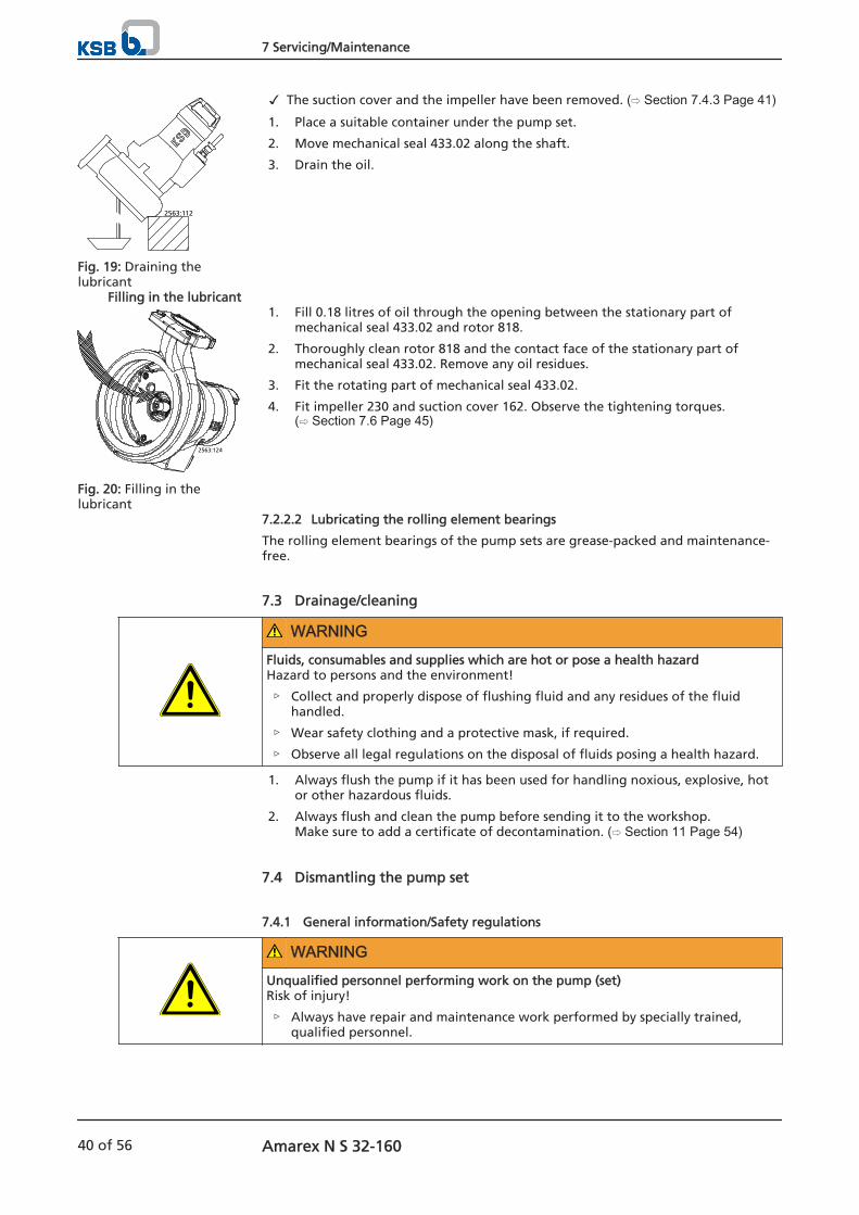
The suction cover and the impeller have been removed. ( Section 7.4.3 Page 41)1. Place a suitable container under the pump set.
2. Move mechanical seal 433.02 along the shaft.
3. Drain the oil.
1. Fill 0.18 litres of oil through the opening between the stationary part ofmechanical seal 433.02 and rotor 818.
2. Thoroughly clean rotor 818 and the contact face of the stationary part ofmechanical seal 433.02. Remove any oil residues.
3. Fit the rotating part of mechanical seal 433.02.
4. Fit impeller 230 and suction cover 162. Observe the tightening torques.( Section 7.6 Page 45)
7.2.2.2 Lubricating the rolling element bearings
The rolling element bearings of the pump sets are grease-packed and maintenance-free.
7.3 Drainage/cleaning
WARNINGFluids, consumables and supplies which are hot or pose a health hazardHazard to persons and the environment!
▷ Collect and properly dispose of flushing fluid and any residues of the fluidhandled.
▷ Wear safety clothing and a protective mask, if required.
▷ Observe all legal regulations on the disposal of fluids posing a health hazard.
1. Always flush the pump if it has been used for handling noxious, explosive, hotor other hazardous fluids.
2. Always flush and clean the pump before sending it to the workshop.Make sure to add a certificate of decontamination. ( Section 11 Page 54)
7.4 Dismantling the pump set
7.4.1 General information/Safety regulations
WARNINGUnqualified personnel performing work on the pump (set)Risk of injury!
▷ Always have repair and maintenance work performed by specially trained,qualified personnel.
2563:112
Fig. 19: Draining thelubricant
Filling in the lubricant
2563:124
Fig. 20: Filling in thelubricant
7 Servicing/Maintenance
40 of 56 Amarex N S 32-160

WARNINGHot surfaceRisk of injury!
▷ Allow the pump set to cool down to ambient temperature.
WARNINGImproper lifting/moving of heavy assemblies or componentsPersonal injury and damage to property!
▷ Use suitable transport devices, lifting equipment and lifting tackle to moveheavy assemblies or components.
Observe the general safety instructions and information. ( Section 7 Page 36)For dismantling and reassembly observe the general assembly drawing.
In the event of damage you can always contact our service staff.
DANGER
Insufficient preparation of work on the pump (set)Risk of injury!
▷ Properly shut down the pump set.
▷ Close the shut-off elements in suction and discharge line.
▷ Drain the pump and release the pump pressure.
▷ Close any auxiliary connections.
▷ Allow the pump set to cool down to ambient temperature.
WARNINGComponents with sharp edgesRisk of cutting or shearing injuries!
▷ Always use appropriate caution for installation and dismantling work.
▷ Wear work gloves.
7.4.2 Preparing the pump set
The notes and steps stated in ( Section 7.4.1 Page 40) have been observed/carried out.
1. De-energise the pump set and secure it against unintentional start-up.
7.4.3 Dismantling the pump section
Dismantle the pump section in accordance with the relevant general assemblydrawing.
1. Remove suction cover 162.
2. Undo and remove the M8 impeller fastening screw. The impeller/shaft connection is a tapered fit.
3. For removing the impeller, an M10 jacking thread is provided at the impellerhub. Screw in the jack as shown in the drawing below and remove the impeller.
7 Servicing/Maintenance
Amarex N S 32-160 41 of 56
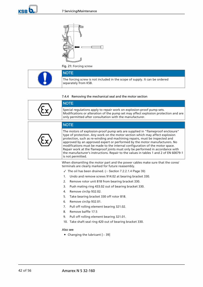
Fig. 21: Forcing screw
NOTEThe forcing screw is not included in the scope of supply. It can be orderedseparately from KSB.
7.4.4 Removing the mechanical seal and the motor section
NOTESpecial regulations apply to repair work on explosion-proof pump sets.Modifications or alteration of the pump set may affect explosion protection and areonly permitted after consultation with the manufacturer.
NOTEThe motors of explosion-proof pump sets are supplied in "flameproof enclosure"type of protection. Any work on the motor section which may affect explosionprotection, such as re-winding and machining repairs, must be inspected andapproved by an approved expert or performed by the motor manufacturers. Nomodifications must be made to the internal configuration of the motor space.Repair work at the flameproof joints must only be performed in accordance withthe manufacturer's instructions. Repair to the values in tables 1 and 2 of EN 60079-1is not permitted.
When dismantling the motor part and the power cables make sure that the cores/terminals are clearly marked for future reassembly.
The oil has been drained. ( Section 7.2.2.1.4 Page 39)1. Undo and remove screws 914.02 at bearing bracket 330.
2. Remove rotor unit 818 from bearing bracket 330.
3. Push mating ring 433.02 out of bearing bracket 330.
4. Remove circlip 932.02.
5. Take bearing bracket 330 off rotor 818.
6. Remove circlip 932.01.
7. Pull off rolling element bearing 321.02.
8. Remove baffle 17.5
9. Pull off rolling element bearing 321.01.
10. Take shaft seal ring 420 out of bearing bracket 330.
Also see
Changing the lubricant [ 39]
7 Servicing/Maintenance
42 of 56 Amarex N S 32-160
7.5 Reassembling the pump set
7.5.1 General information/Safety regulations
WARNINGImproper lifting/moving of heavy assemblies or componentsPersonal injury and damage to property!
▷ Use suitable transport devices, lifting equipment and lifting tackle to moveheavy assemblies or components.
CAUTIONImproper reassemblyDamage to the pump!
▷ Reassemble the pump (set) in accordance with the general rules of soundengineering practice.
▷ Use original spare parts only.
NOTEBefore reassembling the motor section, check that all joints relevant to explosionprotection (flamepaths) are undamaged. Any components with damagedflamepaths must be replaced. Refer to the "Flamepaths" annex for the position ofthe flamepaths.
Always reassemble the pump set in accordance with the corresponding generalassembly drawing.
O-rings
– Check O-rings for any damage and replace by new O-rings, if required.
Assembly adhesives
– Avoid the use of assembly adhesives, if possible.
For reassembly, tighten all screws and bolts as specified in this manual. ( Section 7.6Page 45)
7.5.2 Reassembling the pump section
7.5.2.1 Fitting the mechanical seal
Observe the following points to ensure trouble-free operation of the mechanicalseal:
The shaft surface must be absolutely clean and undamaged.
Immediately before installing the mechanical seal, wet the contact faces with adrop of oil.
For easier installation of bellows-type mechanical seals, wet the inside diameterof the bellows with soapy water (not oil).
To prevent any damage to the rubber bellows, place a thin foil (of approximately0.1 to 0.3 mm thickness) around the free shaft stub. Slip the rotating assembly over the foil into its installation position. Then remove the foil.
Shaft 210, shaft seal ring 420, rolling element bearings 321.01/02 and baffle 17-5have been properly fitted in bearing bracket 330.
1. Install the stationary part of mechanical seal 433.02 in bearing bracket 330 inaccordance with the instructions.
2. Press O-ring 412.03 into bearing bracket 330.
3. Fill in oil. ( Section 7.2.2.1.4 Page 39)4. Slide the rotating assembly of mechanical seal 433.02 onto shaft 210.
Sequence
Sealing elements
Tightening torques
7 Servicing/Maintenance
Amarex N S 32-160 43 of 56
7.5.2.2 Fitting the impeller
7.5.2.2.1 Fitting impeller type S and cutter
NOTEMake sure that the conical impeller hub and the conical part of the shaft areundamaged and assembled free from grease.
1. Slide impeller 230 onto the shaft end.
2. Insert grooved pin 561 into impeller 230.
3. Place impeller body 23-7 on the centring hub.
4. Insert impeller screw 914.04 and tighten it to a torque of 30 Nm.
5. Fasten ring 500 in the suction cover with screws 914.06.
CAUTIONIncorrect assemblyClearance gap inaccurate!
▷ Pull the rotor assembly right up to the suction cover until it will not go anyfurther. Maintain this position until dimensions x and y have been measured.
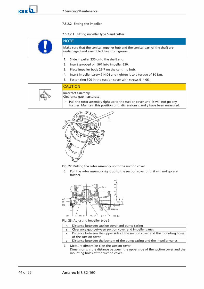
Fig. 22: Pulling the rotor assembly up to the suction cover
6. Pull the rotor assembly right up to the suction cover until it will not go anyfurther.
2563:114
Fig. 23: Adjusting impeller type S
h Distance between suction cover and pump casings Clearance gap between suction cover and impeller vanesx Distance between the upper side of the suction cover and the mounting holes
of the suction covery Distance between the bottom of the pump casing and the impeller vanes
7. Measure dimension x on the suction cover Dimension x is the distance between the upper side of the suction cover and themounting holes of the suction cover.
7 Servicing/Maintenance
44 of 56 Amarex N S 32-160
8. Measure dimension y between the pump casing and the impeller vanes. Dimension y is the distance between the bottom of the pump casing and theimpeller vanes.
9. Use screws 904 to set dimension h (h = x + s - y), where s (0.3 + -0.1) is the clearance between the suction cover and the impellervanes.
10. Tighten the suction cover with screws 914.03.
11. Rotate the impeller body to check that the impeller turns smoothly.Make sure that the suction cover and impeller do not touch each other.
7.5.3 Reassembling the motor section
NOTEBefore reassembling the motor section, check that all joints relevant to explosionprotection (flamepaths) are undamaged. Replace any components whoseflamepaths are damaged. Only use original spare parts made by KSB for explosion-proof pumps. Refer to the "Flamepaths" annex for the position of the flamepaths.
DANGER
Wrong screws/boltsExplosion hazard!
▷ Always use the original screws/bolts for assembling an explosion-proof pumpset.
▷ Never use screws/bolts of different dimensions or of a lower property class.
7.5.4 Checking the connection of motor/power supply
Once reassembly has been completed, carry out the steps described in ( Section 7.2.1Page 37) .
7.6 Tightening torques
Table 18: Tightening torques
Thread Torque [Nm]M 6 7,3M 8 17
Impeller screw 30
7.7 Spare parts stock
NOTEFor explosion-proof pump sets only original spare parts or parts authorised by themanufacturer must be used.
7.7.1 Ordering spare parts
Always quote the following data when ordering replacement or spare parts:
Pump type
KSB order number
Motor number
Refer to the name plate for all data.
Also supply the following data:
Description
7 Servicing/Maintenance
Amarex N S 32-160 45 of 56
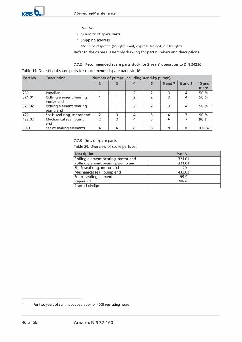
Part No.
Quantity of spare parts
Shipping address
Mode of dispatch (freight, mail, express freight, air freight)
Refer to the general assembly drawing for part numbers and descriptions.
7.7.2 Recommended spare parts stock for 2 years' operation to DIN 24296
Table 19: Quantity of spare parts for recommended spare parts stock8)
Part No. Description Number of pumps (including stand-by pumps)
2 3 4 5 6 and 7 8 and 9 10 andmore
230 Impeller 1 1 2 2 3 4 50 %321.01 Rolling element bearing,
motor end1 1 2 2 3 4 50 %
321.02 Rolling element bearing,pump end
1 1 2 2 3 4 50 %
420 Shaft seal ring, motor end 2 3 4 5 6 7 90 %433.02 Mechanical seal, pump
end2 3 4 5 6 7 90 %
99-9 Set of sealing elements 4 6 8 8 9 10 100 %
7.7.3 Sets of spare parts
Table 20: Overview of spare parts set
Description Part No.Rolling element bearing, motor end 321.01Rolling element bearing, pump end 321.02Shaft seal ring, motor end 420Mechanical seal, pump end 433.02Set of sealing elements 99-9Repair kit 99-201 set of circlips -
8) For two years of continuous operation or 4000 operating hours
7 Servicing/Maintenance
46 of 56 Amarex N S 32-160
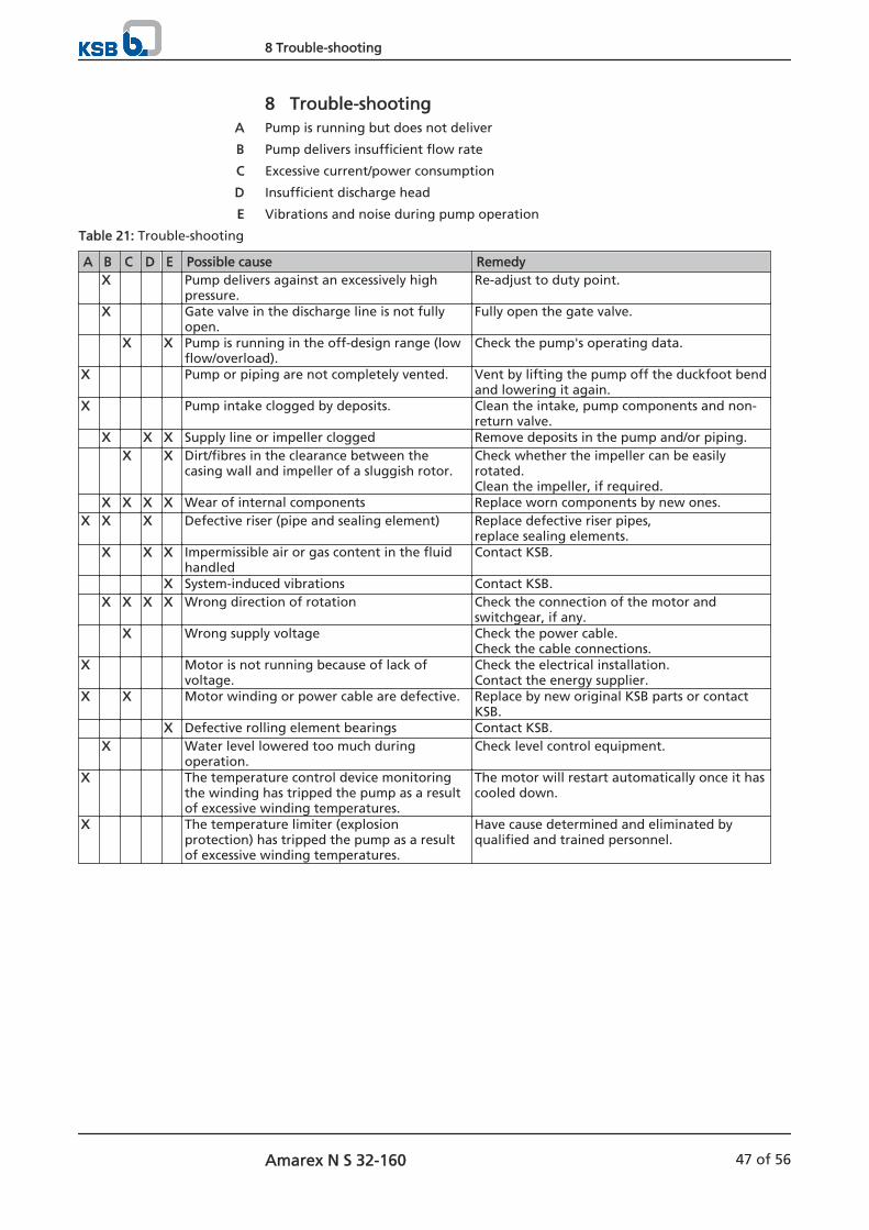
8 Trouble-shootingPump is running but does not deliver
Pump delivers insufficient flow rate
Excessive current/power consumption
Insufficient discharge head
Vibrations and noise during pump operation
Table 21: Trouble-shooting
A B C D E Possible cause Remedy X Pump delivers against an excessively high
pressure.Re-adjust to duty point.
X Gate valve in the discharge line is not fullyopen.
Fully open the gate valve.
X X Pump is running in the off-design range (lowflow/overload).
Check the pump's operating data.
X Pump or piping are not completely vented. Vent by lifting the pump off the duckfoot bendand lowering it again.
X Pump intake clogged by deposits. Clean the intake, pump components and non-return valve.
X X X Supply line or impeller clogged Remove deposits in the pump and/or piping. X X Dirt/fibres in the clearance between the
casing wall and impeller of a sluggish rotor.Check whether the impeller can be easilyrotated.Clean the impeller, if required.
X X X X Wear of internal components Replace worn components by new ones.X X X Defective riser (pipe and sealing element) Replace defective riser pipes,
replace sealing elements. X X X Impermissible air or gas content in the fluid
handledContact KSB.
X System-induced vibrations Contact KSB. X X X X Wrong direction of rotation Check the connection of the motor and
switchgear, if any. X Wrong supply voltage Check the power cable.
Check the cable connections.X Motor is not running because of lack of
voltage.Check the electrical installation.Contact the energy supplier.
X X Motor winding or power cable are defective. Replace by new original KSB parts or contactKSB.
X Defective rolling element bearings Contact KSB. X Water level lowered too much during
operation.Check level control equipment.
X The temperature control device monitoringthe winding has tripped the pump as a resultof excessive winding temperatures.
The motor will restart automatically once it hascooled down.
X The temperature limiter (explosionprotection) has tripped the pump as a resultof excessive winding temperatures.
Have cause determined and eliminated byqualified and trained personnel.
A
B
C
D
E
8 Trouble-shooting
Amarex N S 32-160 47 of 56
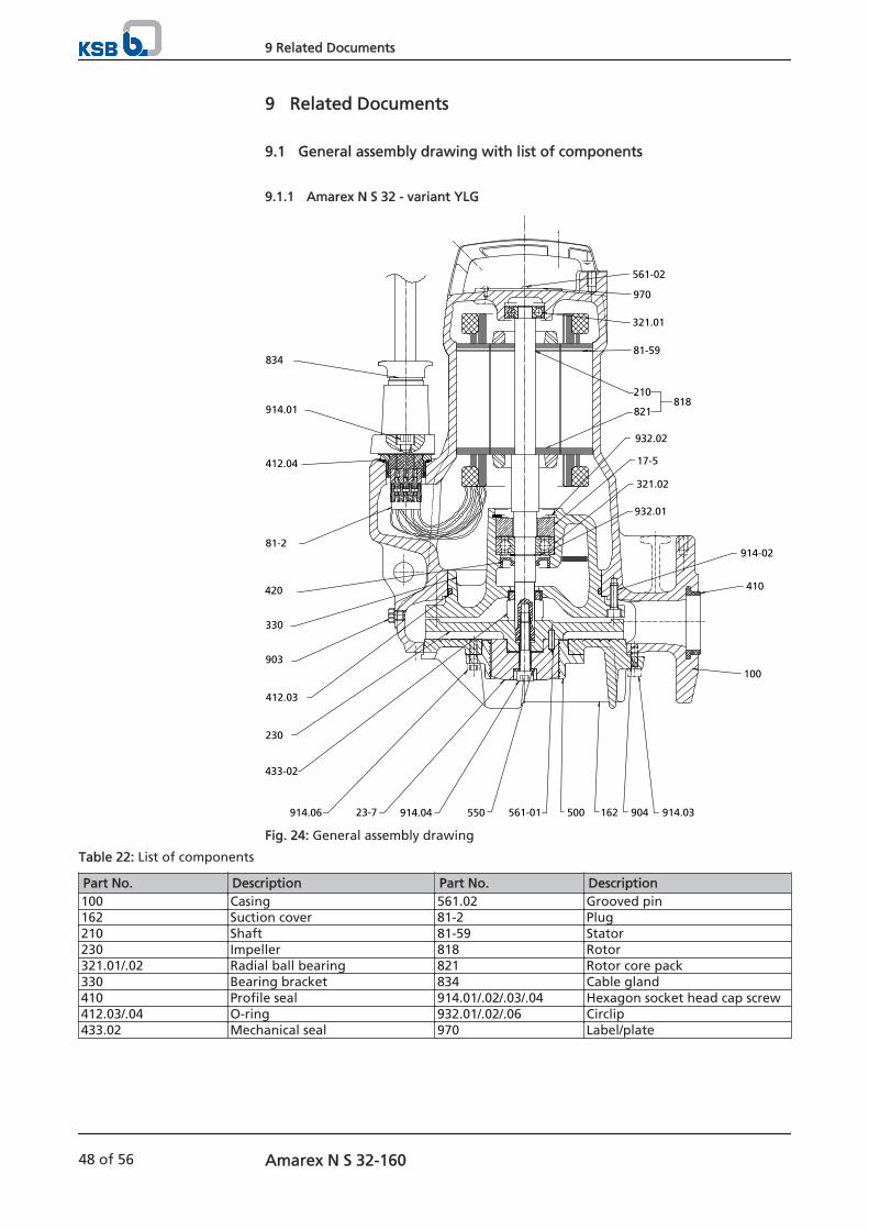
9 Related Documents
9.1 General assembly drawing with list of components
9.1.1 Amarex N S 32 - variant YLG
834
914.01
412.04
81-2
420
330
903
412.03
230
433-02
914.06 23-7 914.04 550 561-01 500 162 904 914.03
100
410
914-02
932.01
321.02
17-5
932.02
210
821818
81-59
321.01
970
561-02
Fig. 24: General assembly drawing
Table 22: List of components
Part No. Description Part No. Description100 Casing 561.02 Grooved pin162 Suction cover 81-2 Plug210 Shaft 81-59 Stator230 Impeller 818 Rotor321.01/.02 Radial ball bearing 821 Rotor core pack330 Bearing bracket 834 Cable gland410 Profile seal 914.01/.02/.03/.04 Hexagon socket head cap screw412.03/.04 O-ring 932.01/.02/.06 Circlip433.02 Mechanical seal 970 Label/plate
9 Related Documents
48 of 56 Amarex N S 32-160
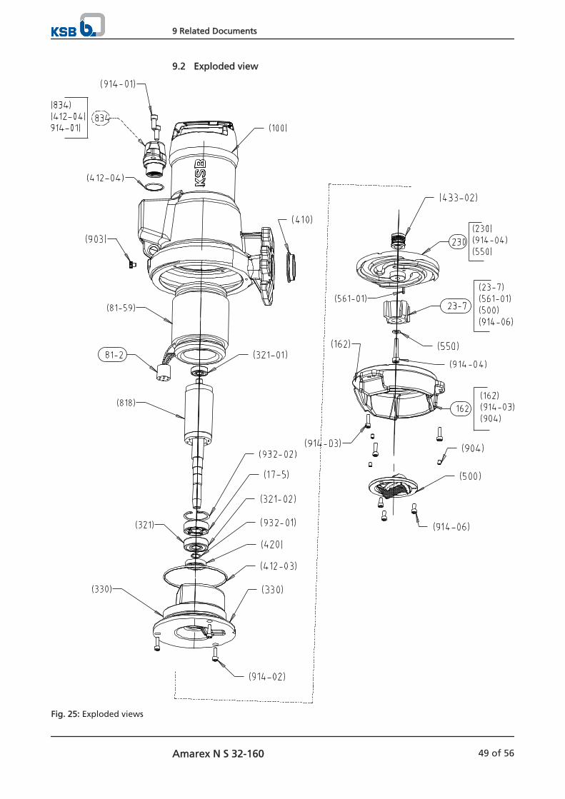
9.2 Exploded view
Fig. 25: Exploded views
9 Related Documents
Amarex N S 32-160 49 of 56
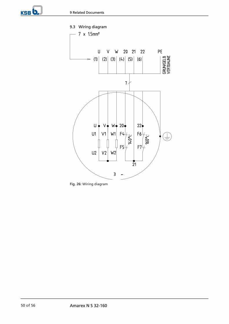
9.3 Wiring diagram
C C
Fig. 26: Wiring diagram
9 Related Documents
50 of 56 Amarex N S 32-160
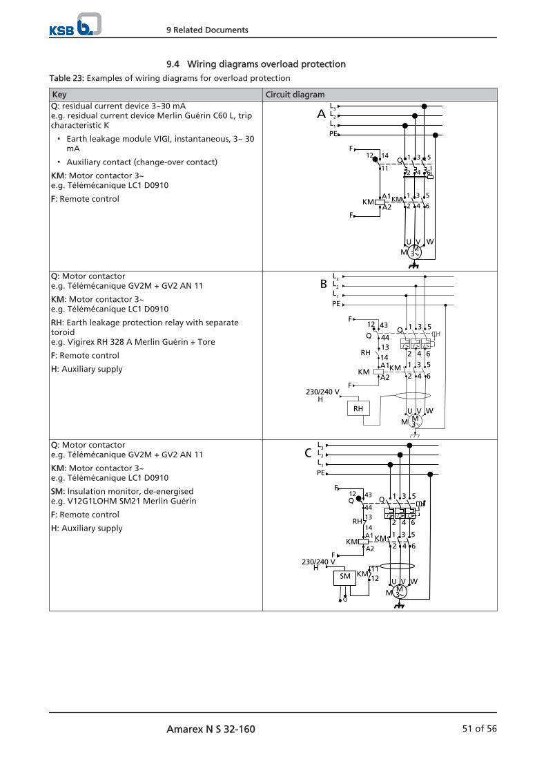
9.4 Wiring diagrams overload protection
Table 23: Examples of wiring diagrams for overload protection
Key Circuit diagramQ: residual current device 3~30 mAe.g. residual current device Merlin Guérin C60 L, tripcharacteristic K
Earth leakage module VIGI, instantaneous, 3~ 30mA
Auxiliary contact (change-over contact)
KM: Motor contactor 3~e.g. Télémécanique LC1 D0910
F: Remote control
12 14
11
A1KM
PE
L3L2
L1
KM
Q
MMU V W
A2
1 3 5
642
3
3
51
2 4 6
F
F
Q: Motor contactore.g. Télémécanique GV2M + GV2 AN 11
KM: Motor contactor 3~e.g. Télémécanique LC1 D0910
RH: Earth leakage protection relay with separatetoroide.g. Vigirex RH 328 A Merlin Guérin + Tore
F: Remote control
H: Auxiliary supply
12 43
44
A11413
RH
230/240 V
PE
L3L2
L1
KMKM
MM
RHH
U V W
A2
1 3 5
3
3
51
2 4 6
2 4 6
F
F
Q: Motor contactore.g. Télémécanique GV2M + GV2 AN 11
KM: Motor contactor 3~e.g. Télémécanique LC1 D0910
SM: Insulation monitor, de-energisede.g. V12G1LOHM SM21 Merlin Guérin
F: Remote control
H: Auxiliary supply
12 43
44
A114
13
1112
RH
230/240 V
PE
L3L2
L1
KMKM
KM
Q Q
MM
SMH
U V W
A2
1 3 5
3
3
51
2 4 6
2 4 6
F
F
9 Related Documents
Amarex N S 32-160 51 of 56

9.5 Flamepaths on explosion-proof motors
Table 24: Overview of flamepaths
Motor sizes Pump set DKN 72
S 32-160
Shaft Baffle Motor housing Cable glandFlamepath number 1 2 3 4Length of flamepath [mm] ≥ 12.5 ≥ 12.5 ≥ 12.5 ≥ 12.5Inside diameter (drilled hole) [mm] 19,25 48 124 32Outside diameter (shaft) [mm] 19 48 124 32Tolerance ISO inside diameter K6 H7 H8 H8Tolerance ISO outside diameter k6 g6 g7 -Tolerance in µm insidediameter to DIN ISO286/2
Max. +2 +25 +63 +39Min. -11 0 0 0
Tolerance in µmoutside diameter toDIN ISO 286/2
Max. +15 -9 -14 -Min. +2 -25 -54 -
Tolerance in µm insidediameter
Max. - - - -Min. - - - -
Tolerance in µmoutside diameter
Max. - - - -25Min. - - - -75
9 Related Documents
52 of 56 Amarex N S 32-160
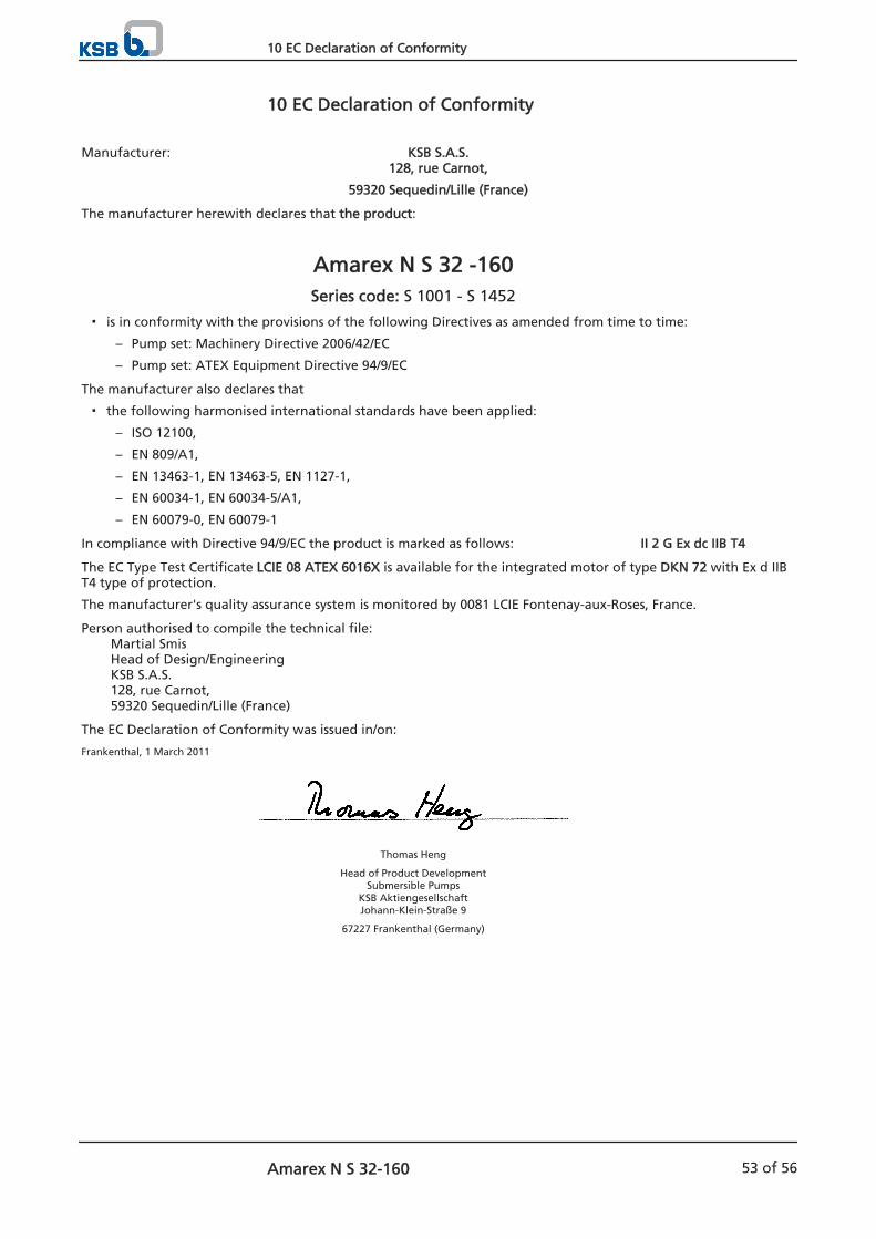
10 EC Declaration of Conformity
Manufacturer: KSB S.A.S.128, rue Carnot,
59320 Sequedin/Lille (France)
The manufacturer herewith declares that the product:
Amarex N S 32 -160Series code: S 1001 - S 1452
is in conformity with the provisions of the following Directives as amended from time to time:
– Pump set: Machinery Directive 2006/42/EC
– Pump set: ATEX Equipment Directive 94/9/EC
The manufacturer also declares that
the following harmonised international standards have been applied:
– ISO 12100,
– EN 809/A1,
– EN 13463-1, EN 13463-5, EN 1127-1,
– EN 60034-1, EN 60034-5/A1,
– EN 60079-0, EN 60079-1
In compliance with Directive 94/9/EC the product is marked as follows: II 2 G Ex dc IIB T4
The EC Type Test Certificate LCIE 08 ATEX 6016X is available for the integrated motor of type DKN 72 with Ex d IIBT4 type of protection.
The manufacturer's quality assurance system is monitored by 0081 LCIE Fontenay-aux-Roses, France.
Person authorised to compile the technical file: Martial Smis
Head of Design/EngineeringKSB S.A.S.128, rue Carnot,59320 Sequedin/Lille (France)
The EC Declaration of Conformity was issued in/on:
Frankenthal, 1 March 2011
Thomas Heng
Head of Product DevelopmentSubmersible Pumps
KSB AktiengesellschaftJohann-Klein-Straße 9
67227 Frankenthal (Germany)
10 EC Declaration of Conformity
Amarex N S 32-160 53 of 56
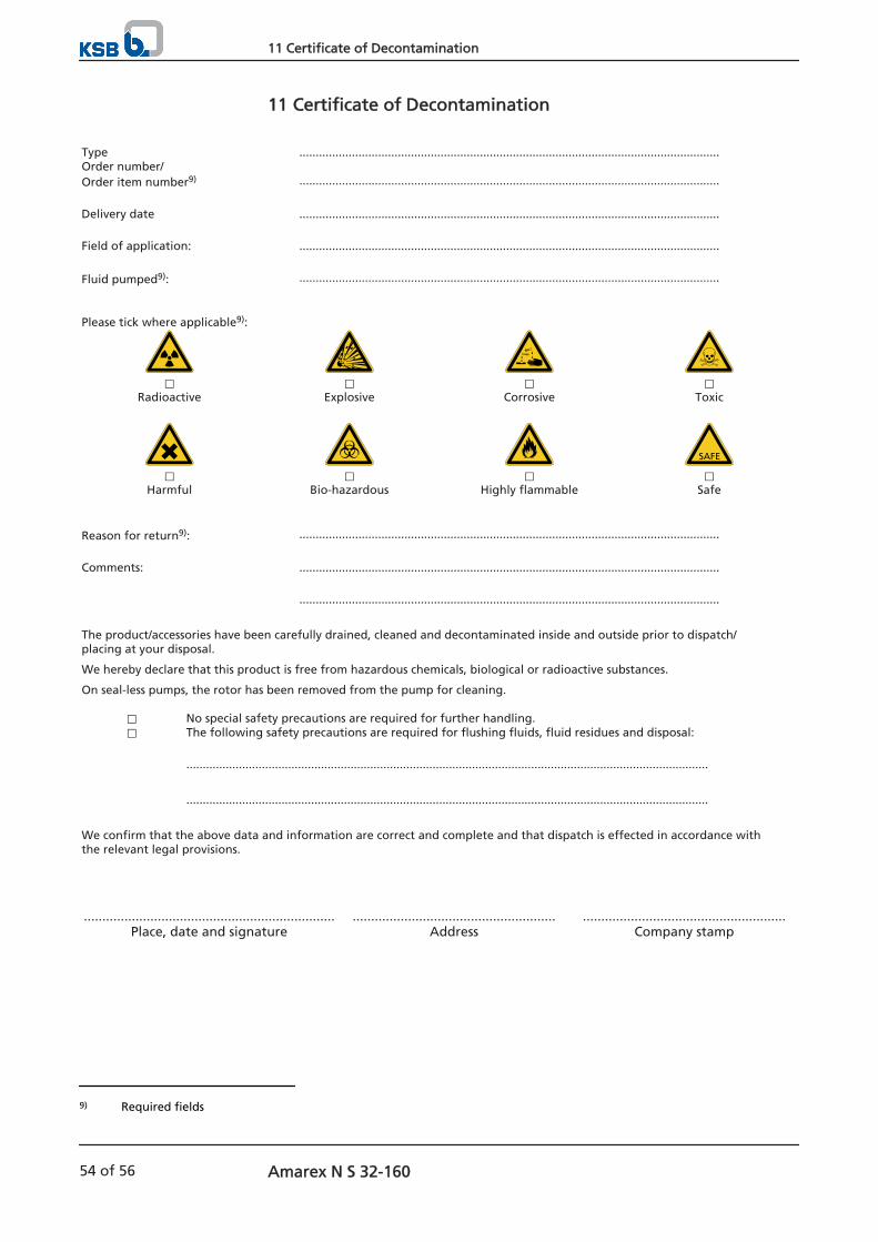
11 Certificate of Decontamination
Type ................................................................................................................................Order number/Order item number9) ................................................................................................................................
Delivery date ................................................................................................................................ Field of application: ................................................................................................................................ Fluid pumped9): ................................................................................................................................
Please tick where applicable9):
⃞ ⃞ ⃞ ⃞Radioactive Explosive Corrosive Toxic
⃞ ⃞ ⃞ ⃞Harmful Bio-hazardous Highly flammable Safe
Reason for return9): ................................................................................................................................
Comments: ................................................................................................................................ ................................................................................................................................
The product/accessories have been carefully drained, cleaned and decontaminated inside and outside prior to dispatch/placing at your disposal.
We hereby declare that this product is free from hazardous chemicals, biological or radioactive substances.
On seal-less pumps, the rotor has been removed from the pump for cleaning.
⃞ No special safety precautions are required for further handling.⃞ The following safety precautions are required for flushing fluids, fluid residues and disposal:
...............................................................................................................................................................
...............................................................................................................................................................
We confirm that the above data and information are correct and complete and that dispatch is effected in accordance withthe relevant legal provisions.
.................................................................... ....................................................... .......................................................Place, date and signature Address Company stamp
9) Required fields
11 Certificate of Decontamination
54 of 56 Amarex N S 32-160
Index
CCertificate of decontamination 54Commissioning/start-up 32
DDirection of rotation 20Dismantling 41Disposal 13
EExplosion protection 11, 19, 20, 28, 29, 30, 33, 34, 36,37, 45
FFlamepaths 52
IInstallation
Transportable model 26Insulation resistance measurement 37Intended use 8
LLevel control 28Lubricant 38
Intervals 37Quality 39
MMaintenance work 37Minimum level of fluid handled 34Misuse 9
OOil lubrication
Oil quality 39Operating limits 8Order number 6Other applicable documents 6Overload protection device 27
PPartly completed machinery 6Permissible flange loads 22Piping 22Power supply 29Preservation 12
RReassembly 41Return to supplier 13Returning to service 35
SSafety 8Safety awareness 10Scope of supply 17Sensors 28Shutdown 35Spare parts stock 46Start-up 32Storage 12, 35Supply voltage 33
TTightening torques 45Trouble-shooting 47
Index
Amarex N S 32-160 55 of 56

2563
.82/
04-EN
P.O. h91257 Pegnitz Bahnhofsplatz 1, 91257 PegnitzHGermanyI !.T"C924171#h9T"C924171#1793
B. P. 95 h 59482 Haubourdin-Cedex • 128,rue Carnoth59320Sequedin/LilleH9 Ia!.T<<3 20227000h9T<<3 20227099h333.(.)
![ksb-ersatzteile.deksb-ersatzteile.de/baureihenhefte/Amarex KRT.pdf,ku 1xw]hq (lqh /|vxqj glh krkh 6wdqg]hlwhq jdudqwlhuw xqg nxu]]hlwlj idovfkh 'uhkulfkwxqj yhu]hlkw /hlwxqjvgxufki](https://img.dokumen.tips/doc/110x75/5b0498687f8b9a8c688dec51/ksb-krtpdfku-1xwhq-lqh-vxqj-glh-krkh-6wdqghlwhq-jdudqwlhuw-xqg-nxuhlwlj.jpg)


![VENTS KSB EC - folheto187 VENTS. Industrial and commercial ventilation 02201 Point Power [W] KSB 100 EC KSB 125 EC KSB 150 EC KSB 160 EC KSB 200 EC KSB 250 EC KSB 315 EC 1 83 83 83](https://img.dokumen.tips/doc/110x75/5e921ded45cff356a6235202/vents-ksb-ec-folheto-187-vents-industrial-and-commercial-ventilation-02201-point.jpg)