Embed Size (px)
Citation preview

Plate-Pakvane mist eliminators
TM

Plate-Pak™
MIST-FREEGAS
LIQUID
GAS AND MIST
MIST-FREEGAS
LIQUID
GAS AND MIST
PLATES RUGGEDLY SECURED BY BOLTS AND SPACERS.
Vertical Flow Configuration:(Same as photo here and on
:)revoc tnorfGas flows up-ward, mist drop-lets strike the plates, and col-lected liquid drains down.
Quality you can count on.
Superior Design: AMACS ,ngised ni esimorpmoc t’nseod construction, and application of Plate-Pak™ units. Mist droplets are thrown out of the gas by multiple gentle angles instead of sharp zig-zags, minimizing disruptive eddies at the corners. Metal plates are held by secure through-bolts and spacers. Details are carefully engineered for each application.
Rugged Construction: Y dna htgnerts eht leef nac uostiffness of a Plate-Pak™ assembly when you walk on it. Thicker plates resist fluttering and last longer in corrosive and erosive ser-vice. Plate-Pak™ units are designed to be installed into vessels and forgotten. After an upset, you won’t find the pieces jammed into the exit pipe or blown downstream into a compressor.
Lower Pressure Drop: Reduced eddy turbulence due to gentle angles means lower pressure drop than for units having sharp corners and drainage hooks. I sa hcus snoitacilppa emos nvacuum towers, that can make all the difference in the world.
Higher E�ciency: Less turbulence around the corners also means minimal re-entrainment of liquid draining eht nwod
plates. The result is higher net efficiency in terms of percent liquid removed: typically 90% of all droplets with diameter 20 microns and larger, 99.9% of 40-micron and larger droplets.
More Throughput: The same reduction of corner swirls allows higher gas velocity and liquid load without losing efficiency due to re-entrainment. Maximum recommended velocity in typical air-water applications, with horizontal flow and about one gallon of liquid per minute per square foot, is about 25 feet per second.
Materials to Suit Your Process: T nommoc tsom eh 613 dna 403 dna leets nobrac era slairetam noitcurtsnoc
stainless steel. But we understand your corrosion requirements sa noitcurtsnoc cillatemnon ro syolla rehto edivorp nac dna
necessary.
Hooked Plates for Special Applications: For horizontal
vanes have short extensions hooking backward from one or more corners. T tneverp pleh ot sresu emos yb derreferp si elyts tahre-entrainment of liquid.
2
:noitarugifnoC wolF latnoziroHGas flows horizontally, detcellocliquid drains down the plates.
leets sselniats lacipyt a fo noitceS sa wolf sag lacitrev rof tinu ™kaP-etalP cillatemnoN .3 egaP no B gniwarD ni
construction is also available. Mist elimina-tors using vanes of this general type are
sometimes called chevron style.
flow applications, AMACS can provide Plate-Pak™ units whose
Mist
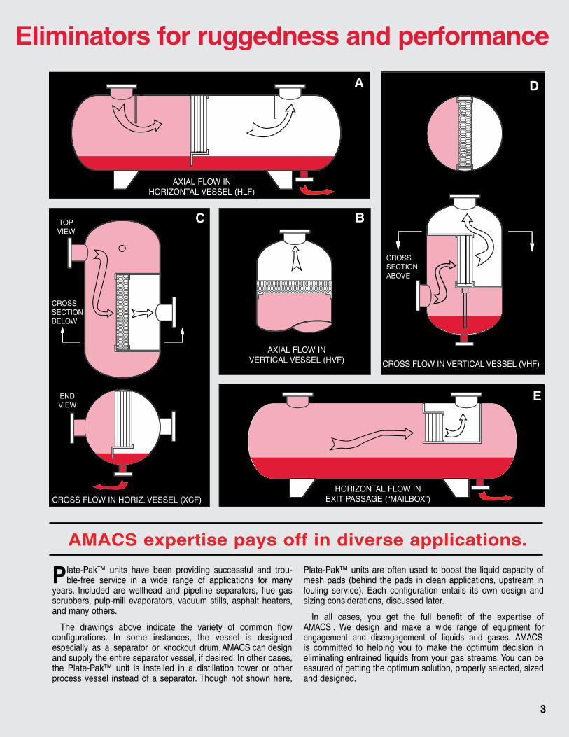
A
BC
E
D
AXIAL FLOW INHORIZONTAL VESSEL (HLF)
TOPVIEW
ENDVIEW
CROSSSECTIONBELOW
AXIAL FLOW INVERTICAL VESSEL (HVF) CROSS FLOW IN VERTICAL VESSEL (VHF)
CROSSSECTIONABOVE
HORIZONTAL FLOW INEXIT PASSAGE (“MAILBOX”)CROSS FLOW IN HORIZ. VESSEL (XCF)
mist Eliminators for ruggedness and performance
AMACS expertise pays off in diverse applications.
Plate-Pak™ units have been providing successful and trou-ble-free service in a wide range of applications for many
years. I sag eulf ,srotarapes enilepip dna daehllew era dedulcnscrubbers, pulp-mill evaporators, vacuum stills, asphalt heaters, and many others.
T wolf nommoc fo yteirav eht etacidni evoba sgniward ehconfigurations. I dengised si lessev eht ,secnatsni emos nespecially as a separator or knockout drum. AMACS can design and supply the entire separator vessel, if desired. In other cases, the Plate-Pak™ unit is installed in a distillation tower or other process vessel instead of a separator. Though not shown here,
Plate-Pak™ units are often used to boost the liquid capacity of mesh pads (behind the pads in clean applications, upstream in fouling service). E dna ngised nwo sti sliatne noitarugifnoc hcasizing considerations, discussed later.
I fo esitrepxe eht fo tifeneb lluf eht teg uoy ,sesac lla nAMACS . We design and make a wide range of equipment for engagement and disengagement of liquids and gases. AMACS is committed to helping you to make the optimum decision in eliminating entrained liquids from your gas streams. You can be assured of getting the optimum solution, properly selected, sized and designed.
3

Capturing droplets by inertial impaction
4
L stinu ™kaP-etalP ,srotanimile tsim epyt-enav rehto ekicapture tiny liquid droplets entrained in a gas or vapor by
a method commonly called inertial impaction. The gas flows either horizontally or upward (See drawings on Page 2), and vanes direct the flowing gas back and forth in a sinuous pat-tern. Mist droplets are carried along by the gas. But because of momentum due to their higher density, the droplets tend to move in straighter lines than the bulk of the gas. At every change in gas direction, some droplets strike and adhere to the surface. This effect can also be likened to the slinging action of a cyclone separa-tor; curving flow around a bend generates centrifugal force, throwing droplets to the outside.
The captured droplets coalesce on the vanes, forming larger drops which have enough weight to trickle down. With vertical flow, collected liquid drips from the bottom of the vane unit and falls
latnoziroh htiW .sag gnisir eht hguorhtflow, a drainage path is provided from the bottom of the vanes.
The performance of a vane-type mist eliminator is influenced by a num-ber of variables as described below. AMACS engineers consider all these factors in selecting and sizing a Plate-Pak™ unit for a particular application, paying special attention to the equation explained on Page 5.
Droplet Size: The smaller a droplet, the more readily it follows the surround-ing bulk gas in flowing around bends. In a given application, nearly all the droplets larger than a certain size are captured, while those smaller than a certain size simply blow through. Vane units are typically considered to be performing well when they capture 99.9% of all droplets larger than about 40 microns.
Relative Densities: The momentum effect necessary for capture depends on the mist droplets’ having an appreciably greater density than the gas. The heavier a droplet of a given size, the more likely it is to strike a vane. But the denser the gas, the more easily it sweeps droplets along without being captured. The parameter most often used to express density effects is the square root of the relative difference in density between liquid and gas: L— G )/ G
Gas Velocity: With a given mixture of gas and mist, a given vane unit operates best in a certain range of gas veloc-ity. If the gas is too slow, the droplets simply drift around the
bends without being captured. But if the gas is too fast, it sweeps liquid off the vanes, a process called re-entrainment. Liquid picked up is broken into droplets; the higher the veloc-ity, the smaller the re-entrained droplets. With vertical flow, high velocity also inhibits the dripping of collected liquid from
the vanes; the resulting buildup of accumulated liquid is called flood-ing. In a typical air-water applica-tion, the maximum velocity is 25 feet per second for horizontal flow an 18 feet per second for vertical flow.
Liquid Capacity: The more rap-idly liquid is captured by a given vane unit, the more liquid builds up on the vanes in the process of draining out, and the lower the gas velocity that can be tolerated with-out re-entrainment. The lower the liquid’s viscosity, the more readily it flows off without re-entrainment.
Vane Contour and Spacing: Tighter bends in the gas path, accompanied by closer spacing of the vanes, accentuate the iner-tial capture effect. Thus, a higher percentage of smaller droplets can be captured. At the same time, the maximum and minimum effec-tive velocities are lowered, and the pressure drop across the vanes for a given velocity goes up. Closer-spaced vanes are also more likely to become obstructed by solid objects, accumulated solid deposits, or high-viscosity liquid. Sharp angles in the vanes cause eddy swirls which increase pressure drop and re-entrain captured liquid more readily. For horizontal flow, some manufac-turers depend on drainage hooks to keep liquid from being blown off sharp corners. Plate-Pak™ units minimize these problems by using
vane contours which more nearly approach curved sinusoi-dal shape, although hooks are available if desired.
Surface Wettability: A vane unit generally performs better if the surface is wettable by entrained liquid. In that case, the captured droplets readily spread out into a film which adheres securely to the vane. If the surface is not wet-table, captured droplets are more likely to be re-entrained. Wettability depends on the composition of the liquid and the surface, the surface roughness and texture, and whether or not there is a film of oil or wax on the surface. It may be influenced by temperature and pressure.
STREAMOF GASCURVESBACK AND FORTHBETWEENPLATES
AT EACH CURVE, LIQUID DROPLETS STRIKEPLATES
CONCEPT OF INERTIAL CAPTURE

The final design of a Plate-Pak™ unit is worked out by AMACS engineers in consultation with customer engineers. T omake sure that the requirements of the particular applica-
tion are met, all the variables described on Page 4 are consid-ered. For purposes of preliminary size estimation, however, a much simpler procedure is sufficient. This involves establishing just one variable: gas velocity. In typical common applications, the optimum or design velocity for a Plate-Pak™ vane unit is determined by the following equation:
ud = K L— G )/ G
ud = optimum design velocity, feet per second; this is the super- ficial or average velocity, the actual volumetric flow rate divided by the cross-sectional area available for flow.
K = an empirically determined constant = 0.65 feet per second for horizontal gas flow = 0.50 feet per second for vertical gas flow
L = density of liquid in mist droplets, in same units as G (usually in pounds per cubic foot)
G = density of gas or vapor in which mist is entrained
T morf yletamixorppa si yticolev fo egnar elbissimrep eh30% to 110% of the calculated design velocity. Consult AMACS engineers about spacing upstream and downstream from the Plate-Pak™ unit.
Preliminary sizing of Plate-Pak™ units for gas velocity
5
CROSSSECTIONABOVE
CROSSSECTIONBELOW
50,000,000 SCFD= 38.9 ACFS
3.61 ft/sec.
44.5” DIA.
INSIDESUPPORT RING
48” DIA.
INSIDE SHELL
10.8 ft2
Find the optimum diameter for a circular Plate-Pak™ ele-ment in a cylindrical separator with vertical axial flow as in the drawing. The gas stream is 50 million standard cubic feet per day (referenced to 60 F and 14.7 psia) with average molecular weight of 25, at 170 F and 250 psig, the entrained liquid having a density of 52 pounds per cubic foot.
Actual gas �ow, ACFS = SCFS (T R / 520)(14.7 / P psia) = (50,000,000 ft3/day) / (86,400 sec/day) x (170 F + 460) / 520 x 14.7 / (250 psig + 14.7) = 38.9 ft3/sec
Gas density, G = Mol. Wt. x P / RT (assuming perfect gas) = 25 x (250 psig + 14.7) / (10.73)(170 F + 460) = 0.979 lb/ft3
Optimum design velocity, ud = K L— G )/ G
= 0.50 52 — 0.979 / 0.979 for vertical flow
= 3.61 ft/sec
Cross-sectional area of Plate-Pak™ unit, A = ACFS / ud = (38.9 ft3/sec) / (3.61 ft/sec)
= 10.8 ft2
Diameter of circular Plate-Pak™ unit, D = 2 A/ = 2 10.8/ = 3.71 feet
= 44.5 inches
Example

For a given mist-elimination task, the most likely alternative to a vane-type unit such as the Plate-Pak™ unit is knitted
mesh pads. AMACS has been a recognized leader in mesh-type mist eliminators for many years, and the Separations & Mass-Transfer Products Division proves expert application assis-tance in deciding among its products. F yranimilerp evitatnet roselection, here are some general guidelines:
Larger Droplets: First, for reasons explained before, vane-type units are not .gof dna tsim enif yrev ot elbacilppa yllareneg Plate-Pak™ separators routinely remove 99.9% of droplets with diameters of 40 microns and above, and 90% of droplets as small as 20 microns. (See graphs below.) For reference, sprays produced by hydraulic and pneumatic nozzles generally have droplet diameters in the range from 10 to 1,000 microns. Droplets blown from a surface condenser or cooling coil typi-cally range from one to 10 microns. And droplets from bubbling liquid as in a boiler may be as small as one micron. (The lower the viscosity and surface tension, the smaller the droplets pro-duced by such entrainment processes.) Droplets created from the bulk of a gas, by chemical reaction or condensation, are generally smaller than one micron. AMACS can provide mesh pads for capturing 99.9% of droplets down to one micron in size.
High Gas Velocity : The maximum and minimum gas velocities for Plate-Pak™ units, in both horizontal and verti-cal flow configurations, are much higher than for mesh pads. When maximum throughput is required in a vessel of a given diameter, a Plate-Pak™ unit is indicated. For reference, a plot on the next page shows the capacity per square foot of a Plate-Pak™ separator with horizontal axial flow in typical natural gas applications.
Low Pressure Drop: Even at the lower design velocities of typical mesh pads, the pressure drop is considerably higher than for a Plate-Pak™ unit at its higher design velocity. In a typical application, the drop is only about 0.1 inch of water. (See graph on next page.) In most cases, the pressure drop would be negligible for both types. But a Plate-Pak™ unit may be preferred when very little pressure drop is available for the mist eliminator, as in a multiple-effect evaporator.
High Liquid Load: T tuphguorht fo noitatimil lapicnirp ehin a mesh pad is flooding, meaning choking with liquid due to excessive quantities of mist (or excessive gas velocity, in the case of vertical flow). But liquid loads high enough to affect a Plate-Pak™ unit’s operation are extremely unlikely in ordinary industrial processes.
60
90
80
70
100
0 302624222010
DR
OP
LET
CA
PTU
RE
EFF
ICIE
NC
Y (%
)
AVERAGE GAS VELOCITY (FEET PER SECOND)
8642 281816141250
PLATE-PAK™,20 m DROPS
PLATE-PAK™,30 m DROPS
PLATE-PAK™,40 m DROPS
AMACS WIRE MESHPAD 4BA (0.011-INCHWIRE, 4 INCHES THICK12 lbs/ft3),10 m DROPS
PLATE-PAK™,10 m DROPS
PLATE-PAK™,RE-ENTRAINMENTREGION
6
Capture efficiency versus gas velocity for droplets of various diameters in atypical Plate-Pak™ mist eliminator and for 10-micron droplets in a typical AMACS
mesh pad (air and water at ambient condition and moderate liquid load)
When to use a Plate-Pak™ unit instead of mesh

70 100
PR
ES
SU
RE
DR
OP
AC
RO
SS
PLA
AVERAGE GAS VELOCITY (FEETAA PER SECOND)T
0.1
0.3
0.4
0.2
0.5
1.5
2.0
1.0
0.6
0.8
3.0
405 6 7 8 10 15 20 30
4.050
50
REGION
3
4
2
6
5
8
15
20
30
100 200 300 500 1000 1500OP
TIM
UM
GA
S F
LOW
RAT
E (M
ILLI
ON
S O
F S
CF
PE
R D
AYP
ER
SQ
UA
RE
FO
OT
OF
CR
OS
S-S
EC
TIO
NA
L A
RE
A)
OPERATING PRESSURE (PSIG)AA
10
Extremely Viscous Liquid: The higher the viscosity of the collected liquid, the more slowly it drains from a mesh pad or vane unit, so the greater the accumulation of draining liquid and the likelihood of flooding. Typical mesh pads are unsuitable for appre-ciable loads with liquid viscosities higher than about 100 centi-poise (approximately like honey). Since Plate-Pak™ units drain much more freely, they can handle much higher viscosities.
Accumulated Residues: In some services, solid or semi-solid residues form in the mist eliminator due to processes such as dust capture, evaporation and polymerization. These deposits may be called cake, sludge, varnish, etc. A Plate-Pak™ unit can be cleaned much more easily and economically than a mesh pad, which may have to be replaced instead. Furthermore, it can oper-ate much longer without shutdown due to residues.
Clogging Particulates: Similarly, mesh pads are much more susceptible to clogging by solid particles which are too large to pass through the mesh. Such matter may be called trash, scale, cinders, etc. It may be impractical to clean a clogged pad, so replacement would be required. If potential clogging is expected, it is particularly important to consult with AMACS engineers in the design of the mist eliminator.
Severe Corrosion: In services where corrosion cannot be entirely eliminated by the choice of material, a Plate-Pak™ unit lasts much longer than a mesh pad made of the same substance. This is mainly due to the greater thickness of the vanes, typically
0.030 to 0.050 inch for metal vanes (18 to 26 gage) compared to 0.011 inch for wire mesh.
Surge Bu�eting: When operated within the design ranges of rotanimile-tsim eht fo htgnerts larutcurts eht ,daol dna yticolev
element is of no concern. B tcejbus era hcihw snoitallatsni ni tu detacolsid eb nac sdap hsem ,diuqil ro sag fo segrus tneloiv ot
and even destroyed; Plate-Pak™ units are required on account of their strength and stiffness.
Foam Problems: When the entrained liquid contains foaming agents, agitation in a mesh pad can generate foam that greatly decreases the pad’s efficiency. B siht ot enummi ylevitaler gnieproblem, Plate-Pak™ units are preferred in a foaming environ-ment. They can even break foam which has been generated upstream.
Tandem Mesh and Plate-Pak™ Element: In some circum-stances, a Plate-Pak™ element is useful in combination with a mesh pad. The Plate-Pak™ unit may be mounted upstream, to remove the bulk of a liquid load. This keeps the pad from flooding, thereby preserving its superior efficiency for very fine droplets. (Clogging particulates will also be screened out, as mentioned before.) Or the Plate-Pak™ unit may be mounted downstream. There, it captures relatively large droplets blown from a mesh pad designed to coalesce or agglomerate extremely fine droplets. For proper design of tandem systems, consult with AMACS Engineers.
7
Design flow capacity versus pressure for a typicalPlate-Pak™ mist eliminator with axial flow of
natural gas in a horizontal vessel
Pressure drop versus superficial (average) gasvelocity for a typical Plate-Pak™ unit with air and
water (1 gpm / ft2) at ambient conditions
70 100
PR
ES
SU
RE
DR
OP
AC
RO
SS
PLA
AVERAGE GAS VELOCITY (FEETAA PER SECOND)T
0.1
0.3
0.4
0.2
0.5
1.5
2.0
1.0
0.6
0.8
3.0
405 6 7 8 10 15 20 30
4.050
50
REGION
3
4
2
6
5
8
15
20
30
100 200 300 500 1000 1500OP
TIM
UM
GA
S F
LOW
RAT
E (M
ILLI
ON
S O
F S
CF
PE
R D
AYP
ER
SQ
UA
RE
FO
OT
OF
CR
OS
S-S
EC
TIO
NA
L A
RE
A)
OPERATING PRESSURE (PSIG)AA
10
unit instead of mesh

MultiPocket® vanes
FIGURE 1
8
The capacity of vertical vanes (with horizontal vapor flow) can also be increased by enhancing
liquid drainage. As discussed, captured liquids are re-entrained when the velocity of the vapor exceeds the ideal velocity. To prevent liquid re-entrainment, the serpentine path offered by the vane is augment-ed with obstructions to allow for the pooling of liquid
with protection from the passing vapor stream. This design increases the capacity of the vane by as much as 45%. In vertical gas compressor knock-out drums, in which the vessel size is dictated by the capacity of the mist eliminator, MultiPocket® vanes considerably reduce the Foot-print and cost of skids.
FIGURE 1. summarizes the approaches used snoisnemid lessev ni noitcuder eht dby AMACS an
possible using these advanced designs.

9
AMACS, previously known as ACS Separation & Mass Transfer Products was awarded US Patent #6,852,146 for a vane-type mist elimi-nator that removes entrained liquid droplets from high-veloc-ity gas streams. Available commercially as the MultiPocket® vane assembly (Figure), it comprises a sheet fabricated from one piece of metal and featuring parallel rows of serpentine-like vanes. These sheets are held in their arrangement by bolts and spacers, not welds, as used in conventional designs. “This design prevents corrosion caused by internal welding and tights radius bends common in other high performance vane designs,” says Kanti Patel, AMACS engineering manager.
The vane blades are configured in such a way as to cre-ate pockets that allow droplets entrained in a gas stream to impinge and cling to the vane, and then drain, without being re-entrained. With horizontal flow, the separated liquid drains perpendicularly to the gas stream, thereby preventing gas-liquid traffic below the Plate-Pak™ vanes. This feature allows higher flows. Third party testing shows that the MultiPocket® vanes exhibited a 3.4 — 14.1% capacity increase before breakthrough (liquid carryover) occurs downstream.
For any given installation thickness of the vanes, the number of pockets, spacing of the vanes, and other parameters can
be varied to achieve the desired separation. The prefabricated unit comes in either a single piece ready for installation, or in smaller sections that can be installed through a vessel man-way. To complete the installation a fabricated housing and a liquid drain are added, followed by welding or bolting of the entire unit in the vessel.
Gaston Rodriguez, process equipment proposals manager at the Hanover Co. (Houston, TX; www.hanover-co.com) pro-vided the following case data in support of the MultiPocket® vane. A recent application for this product was in a vertical 2-phase scrubber handling 125 million ft3/d of natural gas at an operating pressure of 350 psig and 90 F. Using the MultiPocket® vane allowed for the reduction of the vessel diameter from 60 inches to 54 inches. The material, labor and installation savings was $6,500.
In other applications where pressure drop is critical, such as gas pipeline and utility contracts, the MultiPocket® vane provides the minimum pressure drop at the highest mist elimi-nation efficiency. Tests has shown that for an inlet water spray loading of 2 gpm/ft2 and air velocities of 10–25 ft/s, the pres-sure drop for a horizontal orientation is about 15% less than with the conventional vane.
The MultiPocket® vane is a thin sheet that is formed into hills and valleys. The gas stream enters one side and take a zig-zag path to reach the other side. Pockets formed by partitions allow droplets
entrained in a gas stream to impinge and cling to the vane, and then drain, without being re-entrained.
BackWall
FrontWall
MiddleWall
Gas Flow
Partition
SecondarySpacer
3/8 in.1/8 in.
Two ParallelMultiPocket® vanes
Spacer
1in.
Pockets Improve This Mist Eliminator’s Efficiency
Reprinted with permission from CEP (Chemical Engineering Progress), April 2005.Copyright © 2005 American Institute of Chemical Engineers (AIChE)

10
Company:
Address:
Contact (Name/Title):
TEL: ( )
FAX: ( )
E-mail:
COMPANY INFORMATION
TECHNICAL DATA SHEET MIST ELIMINATION
14211 Industry Street, Houston, Texas 77053Telephone: (713) 434-0934 or (800) 231-0077Fax: E-mail: [email protected]: www.amacs.com
STATE YOUR MIST ELIMINATION APPLICATION
PROCESS CONDITIONS (Provide appropriate units)
VESSEL DETAILS o NEW o EXISTING
DESIRED SEPARATION
MIST ELIMINATOR
SKETCHDia: Ht./Length:
Manway Size: Horiz.: Vert.
Material: Housing Required? o YES o NO
Preferred Type: o Wire Mesh o Vane
Materials:
Remarks:
_____________________% removal of__________________µm Droplets
____________________________________________________________
_____________________ wt% / vol% / ppm in exit gas
Operating Temperature: deg F / deg C Operating Pressure: psia (psig)
Gas Type: Flow Rate: MAX.: MIN.: lb/hr/(acfm)
Vapor Density or SG or Mol. Wt.: Compressibility Factor: Viscosity: cp
Liquid Type: Qty.: gpm Density or SG: Viscosity: cp
Solids/Foulants: o Yes o No If Yes, Explain:

Notes
11

M IST ELIMINATION is one of many liquid-vapor and liquid-liquid separation processes for which AMACS
has been providing effective solutions for more than half a century.AMACS Process Tower Internals is recognized for its leader
in developing separations technology reflected in a of products such as those summarized below. O
ence includes numerous materials of construction
a wide range of conditions. We regularly perform testing and pilot-scale experiments, both in-house
and at customer locations. This unusually broad-based experience works to your advantage by allowing us to understand the total problem, often integrating several ofour products in the solution.
Contact AMACS for resolution of all your difficult mass-transfer and other separation challenges.
Separations technology is our business.
Mesh-type mist eliminators
The exclusive, patented MisterMesh ® drainage for higher throughput and efficiency with reduced pressure drop.
For high efficiency with micron-scale fog, threads such as fiberglass can be “co-knit”
Liquid-liquid coalescersThese units separate immiscible liquids of differing specific gravities. Coalescing of droplets is promoted by knitted mesh, Plate-Pak™ vanes, or both. Meshes with co-knit fibers coalesce extremely fine droplets, such as those generated by centrifugal pumping. The results can be impressive in terms of performance, compactness, and low cost. Similar separators remove traces of oil from wastewater and marine skimmer discharge.
Column packing and internalsAMACS is the sole North American licensee for Julius Montz GmbH sheet metal and wire gauze packing and associated internals. AMACS also supplies high efficiency knitted wire mesh packing. In random (dumped) packing, we supply a wide variety of industry standard and proprietary types in all sizes, both plastic and metal.
Fractionation traysIn providing a complete line of sieve, valve, bubble-cap, and specialty trays, our experienced design engineers meet challenging process demands by applying the latest technologies and software. The company’s strong commitment to testing, research, and development has kept AMACS in a leadership position in mass-transfer technology.
Plate-Pak™ is a trademark and MisterMesh® and MultiPocket® are registered trademarks of AMACS T nitellub siht ni deniatnoc noitamrofni ehis believed to be accurate and reliable but is not to be construed as implying any warranty or guarantee of performance.
AMACS Process Tower Internals 14211 Industry Street Houston, Texas 77053 Telephone: (713) 434-0934 or (800) 231-0077 Fax: (713) 433-6201 Email: [email protected]: www.amacs.com
productcovering
experiurvariety
ship
type Mist Eliminator (photo) enhances
with the mesh.