Embed Size (px)
Citation preview

8/3/2019 Am Pa City 9242004
http://slidepdf.com/reader/full/am-pa-city-9242004 1/17
Electrical Design Training Class
AmpacityWSDOT
Fall / Winter 2004
presented by: Keith Calais

8/3/2019 Am Pa City 9242004
http://slidepdf.com/reader/full/am-pa-city-9242004 2/17
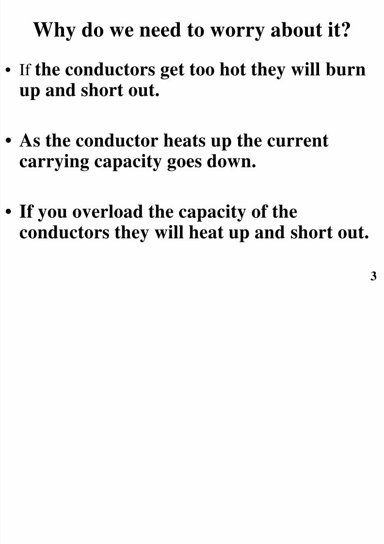
What is it?
• Ampacity is the current, in Amperes, that aconductor can carry continuously under the
conditions of use without exceeding its
temperature rating.
8/3/2019 Am Pa City 9242004
http://slidepdf.com/reader/full/am-pa-city-9242004 3/17

8/3/2019 Am Pa City 9242004
http://slidepdf.com/reader/full/am-pa-city-9242004 4/17
When do we calculate Ampacity?
• Ampacity should be considered every time
you add conductors to a conduit.
• Every time you modify an existing circuit.
• On all new designs the ampacity should bechecked.
4

8/3/2019 Am Pa City 9242004
http://slidepdf.com/reader/full/am-pa-city-9242004 5/175
How do we calculate it?
Ampacity is calculated by using this simple formula:
*I =TC- (TA+Delta TD)
RDC(1+YC)RCA
*All calculations must be checked and approved by a licensed electrical engineer.
Where:
TC=Conductor temperature in degrees Celsius
TA=Ambient temperature in degrees Celsius
DeltaTD=Dielectric loss temperature rise
RDC=dc resistance of conductor at temperature TC
YC= Component ac resistance resulting from skin effect of proximity effect
RCA=Effective thermal resistance between conductor and surrounding ambient
8/3/2019 Am Pa City 9242004
http://slidepdf.com/reader/full/am-pa-city-9242004 6/176
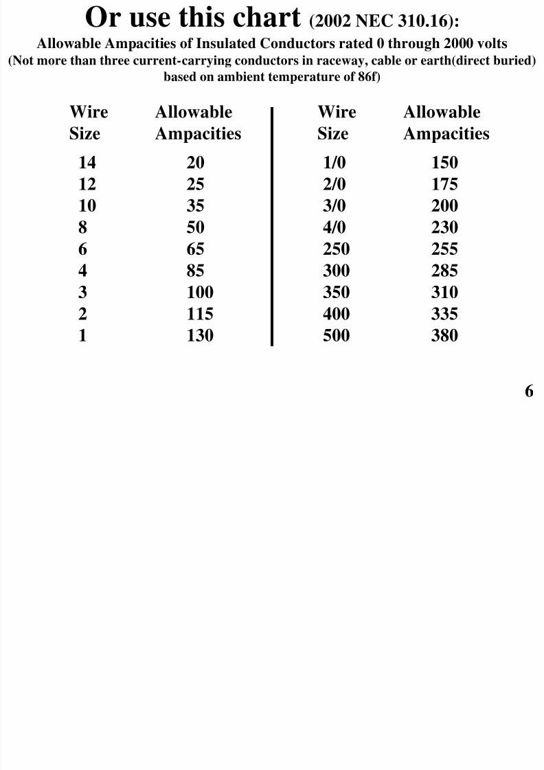
Or use this chart (2002 NEC 310.16):
Allowable Ampacities of Insulated Conductors rated 0 through 2000 volts(Not more than three current-carrying conductors in raceway, cable or earth(direct buried)
based on ambient temperature of 86f)
14 20
12 25
10 358 50
6 65
4 85
3 100
2 115
1 130
Wire
Size
Allowable
Ampacities1/0 150
2/0 175
3/0 2004/0 230
250 255
300 285
350 310
400 335
500 380
Wire
Size
Allowable
Ampacities

8/3/2019 Am Pa City 9242004
http://slidepdf.com/reader/full/am-pa-city-9242004 7/177
Adjustment factors for more than three
current-carrying conductors in araceway or cable. ((2002 NEC 310.15(b)(2)(a))
4-67-9
10-2021-30
31-40
41 and above
80
70
5045
40
35
Number of current
carrying conductors
Percent of values in NEC
Tables 310.16 thru 310.19
8/3/2019 Am Pa City 9242004
http://slidepdf.com/reader/full/am-pa-city-9242004 8/178
Potential Ampacity problems:
• The most common problem is at theconduit leaving the service.
• Large loads (usually ITS Transformers)sharing the same conduit as illuminationcircuits.

8/3/2019 Am Pa City 9242004
http://slidepdf.com/reader/full/am-pa-city-9242004 9/17
Check Ampacity of Wire
• Given: wire run #1 = one 3” conduit, containingIllumination circuit A with 2-#2, Illumination circuit
B with 2-#4, ITS Transformer-ES 325 & CC325
circuit C with 3-#6, ITS-VMS 325 circuit D with 3-
#8 & Traffic Signal #1 circuit E with 3-#8
conductors for a total of 10 current carryingconductors. Note: These conductors are properly
sized for allowable voltage drop. (they are thenumbers we calculated in the Ampacity chapter.)
9

8/3/2019 Am Pa City 9242004
http://slidepdf.com/reader/full/am-pa-city-9242004 10/17
1010
CD
E
3

8/3/2019 Am Pa City 9242004
http://slidepdf.com/reader/full/am-pa-city-9242004 11/17
11
Check Ampacity of Wire - Continued
• Illumination Circuit A load = 16.8 amps Reduce ampacity by 50%.
#2 wire ampacity = 115 amps x 0.5 = 57.5 amps.
16.8 amps < 57.5 amps. OK

8/3/2019 Am Pa City 9242004
http://slidepdf.com/reader/full/am-pa-city-9242004 12/17
Check Ampacity of Wire - Continued
• Illumination Circuit B load = 23.1 amps
Reduce ampacity by 50%.
#4 wire ampacity = 85 amps x 0.5 = 42.5 amps.
23.1 amps < 42.5 amps. OK
12
8/3/2019 Am Pa City 9242004
http://slidepdf.com/reader/full/am-pa-city-9242004 13/17
13
Check Ampacity of Wire - Continued
• ITS-ES 325 & CC 325-Circuit C load = 31.25 amps
Reduce ampacity by 50%.
#6 wire ampacity = 65 amps x 0.5 = 32.5 amps.31.25 amps < 32.5 amps. OK.

8/3/2019 Am Pa City 9242004
http://slidepdf.com/reader/full/am-pa-city-9242004 14/17
14
Check Ampacity of Wire - Continued
• ITS-VMS 325-Circuit D load = 31.5 amps
Reduce ampacity by 50%.
#8 wire ampacity = 50 amps x 0.5 = 25 amps.
31.5 amps > 25 amps. NOT OK.
#6 wire ampacity = 65 amps x 0.5 = 32.5 amps.
31.5 amps < 32.5 amps. OK.

8/3/2019 Am Pa City 9242004
http://slidepdf.com/reader/full/am-pa-city-9242004 15/17
15
Check Ampacity of Wire - Continued
• Signal - Circuit E load = 41.73 ampsReduce ampacity by 50%
#8 wire ampacity = 50 amps x 0.5 = 25 amps.
41.73 amps > 25 amps. NOT OK.
#6 wire ampacity = 65 amps x 0.5 = 32.5 amps.
41.73 > 32.5 amps. NOT OK.
#4 wire ampacity 85 amps x 0.5= 42.5 amps.
41.73 < 42.5 amps. OK

8/3/2019 Am Pa City 9242004
http://slidepdf.com/reader/full/am-pa-city-9242004 16/17
16
3
3
16
CD
E
1

8/3/2019 Am Pa City 9242004
http://slidepdf.com/reader/full/am-pa-city-9242004 17/17
17
AnyQuestions?