Embed Size (px)
Citation preview
L A J O L L A C O M M O N S
P H A S E I I O F F I C E T O W E R
Technical Report 4 Alyssa Stangl
Structural Option Advisor | Dr. Linda Hanagan
General Building Information
La Jolla Commons Phase II Office Tower
Height | 198’ 8” (13 stories)
Square Footage | 462,301 GSF
Location | San Diego, California Seismic Design Category D
Office Building Multi-tenant capabilities
First Class A NetZero Office Building in the USA
Special Features Underfloor Air Distribution System
15 foot cantilevers at both ends
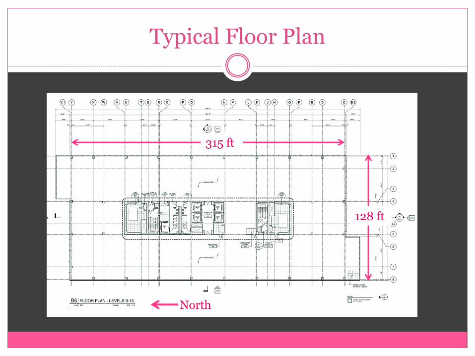
Typical Floor Plan
315 ft
128 ft
North
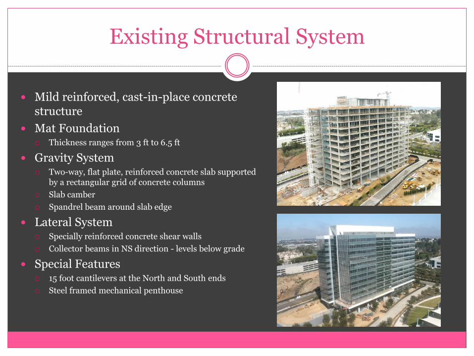
Existing Structural System
Mild reinforced, cast-in-place concrete structure
Mat Foundation Thickness ranges from 3 ft to 6.5 ft
Gravity System Two-way, flat plate, reinforced concrete slab supported
by a rectangular grid of concrete columns
Slab camber
Spandrel beam around slab edge
Lateral System Specially reinforced concrete shear walls
Collector beams in NS direction - levels below grade
Special Features 15 foot cantilevers at the North and South ends
Steel framed mechanical penthouse
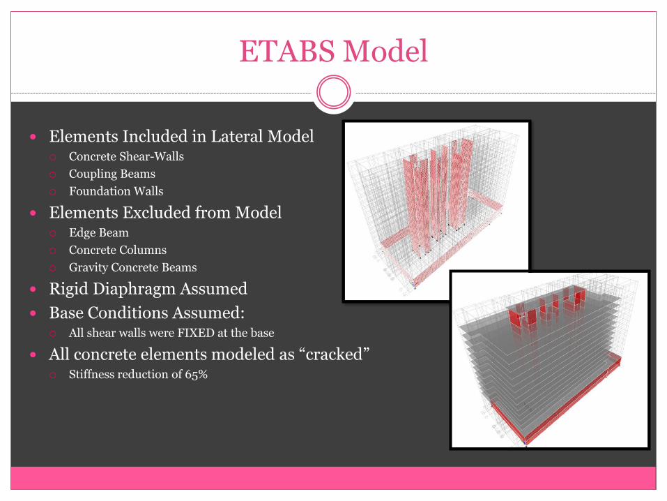
ETABS Model
Elements Included in Lateral Model Concrete Shear-Walls
Coupling Beams
Foundation Walls
Elements Excluded from Model Edge Beam
Concrete Columns
Gravity Concrete Beams
Rigid Diaphragm Assumed
Base Conditions Assumed: All shear walls were FIXED at the base
All concrete elements modeled as “cracked” Stiffness reduction of 65%
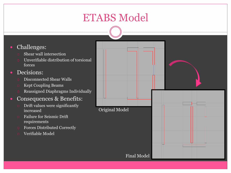
ETABS Model
Challenges: Shear wall intersection
Unverifiable distribution of torsional forces
Decisions: Disconnected Shear Walls
Kept Coupling Beams
Reassigned Diaphragms Individually
Consequences & Benefits: Drift values were significantly
increased
Failure for Seismic Drift requirements
Forces Distributed Correctly
Verifiable Model
Original Model
Final Model
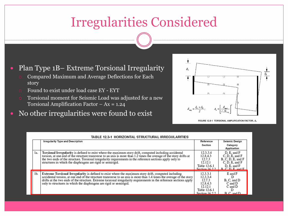
Irregularities Considered
Plan Type 1B– Extreme Torsional Irregularity Compared Maximum and Average Deflections for Each
story
Found to exist under load case EY - EYT
Torsional moment for Seismic Load was adjusted for a new Torsional Amplification Factor – Ax = 1.24
No other irregularities were found to exist
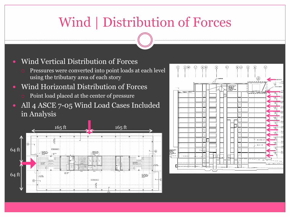
Wind | Distribution of Forces
Wind Vertical Distribution of Forces Pressures were converted into point loads at each level
using the tributary area of each story
Wind Horizontal Distribution of Forces Point load placed at the center of pressure
All 4 ASCE 7-05 Wind Load Cases Included in Analysis
165 ft 165 ft
64 ft
64 ft
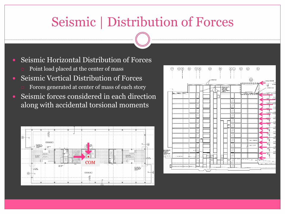
Seismic | Distribution of Forces
Seismic Horizontal Distribution of Forces Point load placed at the center of mass
Seismic Vertical Distribution of Forces Forces generated at center of mass of each story
Seismic forces considered in each direction along with accidental torsional moments
COM

Animation | EX + EXT

Animation | EY + EYT
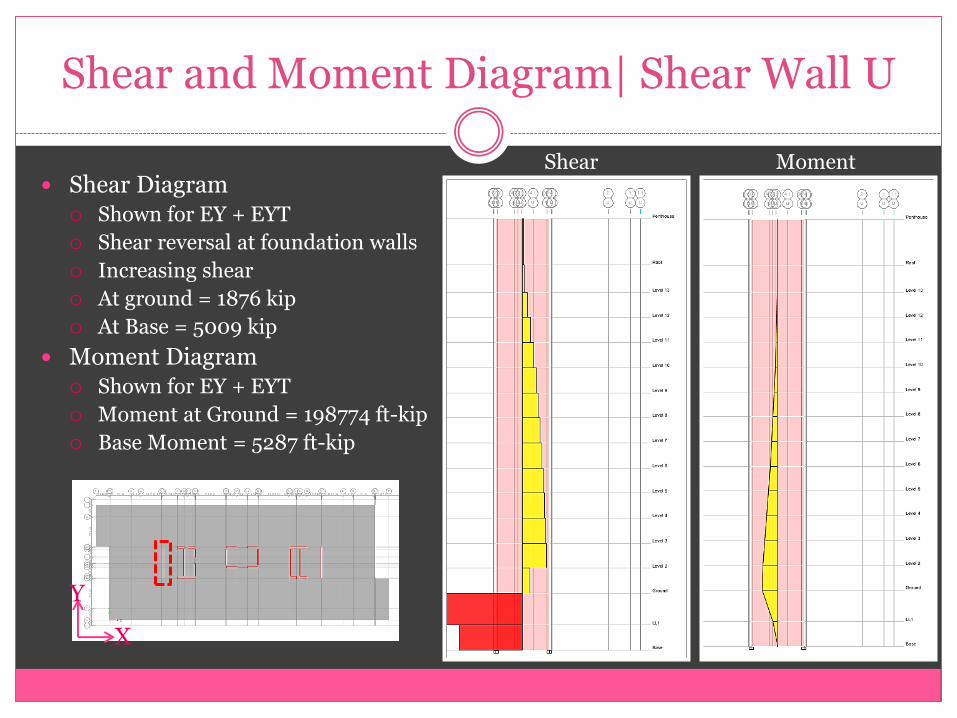
Shear and Moment Diagram| Shear Wall U
Shear Diagram Shown for EY + EYT
Shear reversal at foundation walls
Increasing shear
At ground = 1876 kip
At Base = 5009 kip
Moment Diagram Shown for EY + EYT
Moment at Ground = 198774 ft-kip
Base Moment = 5287 ft-kip
Shear Moment
Y
X
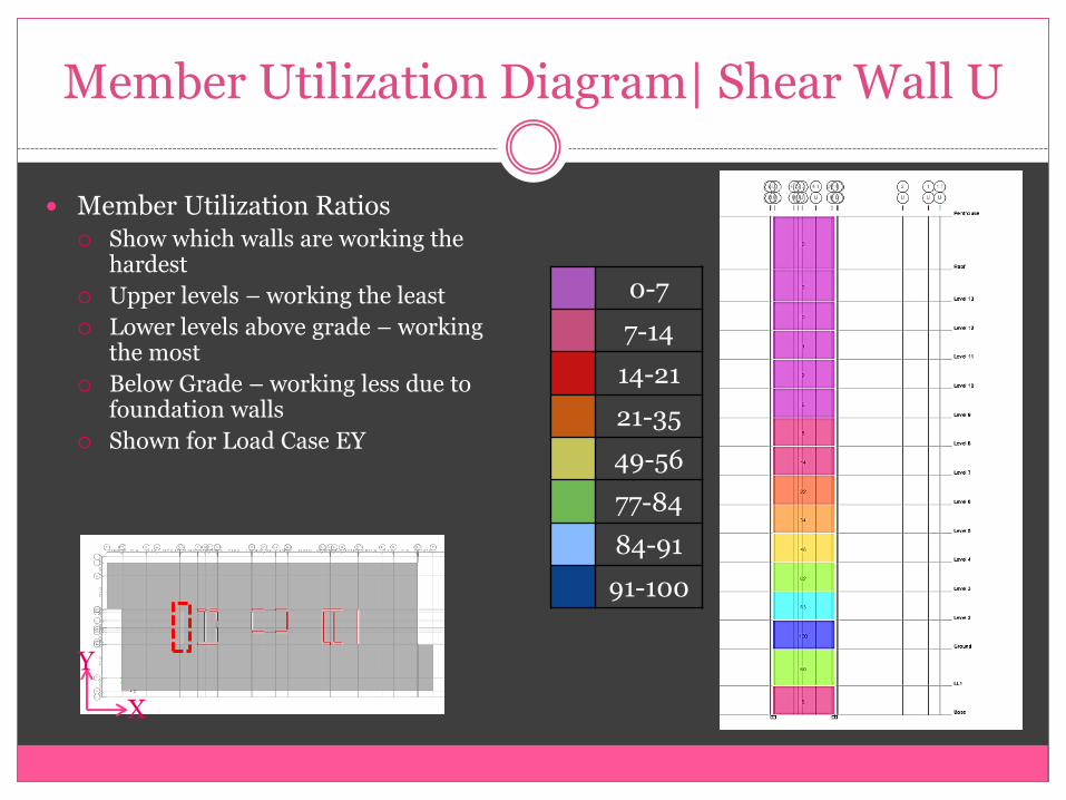
Member Utilization Diagram| Shear Wall U
Member Utilization Ratios Show which walls are working the
hardest
Upper levels – working the least
Lower levels above grade – working the most
Below Grade – working less due to foundation walls
Shown for Load Case EY
0-7
7-14
14-21
21-35
49-56
77-84
84-91
91-100
Y
X
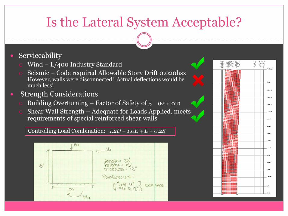
Is the Lateral System Acceptable?
Serviceability Wind – L/400 Industry Standard
Seismic – Code required Allowable Story Drift 0.020hsx However, walls were disconnected! Actual deflections would be much less!
Strength Considerations Building Overturning – Factor of Safety of 5 (EY + EYT)
Shear Wall Strength – Adequate for Loads Applied, meets requirements of special reinforced shear walls
Controlling Load Combination: 1.2D + 1.0E + L + 0.2S
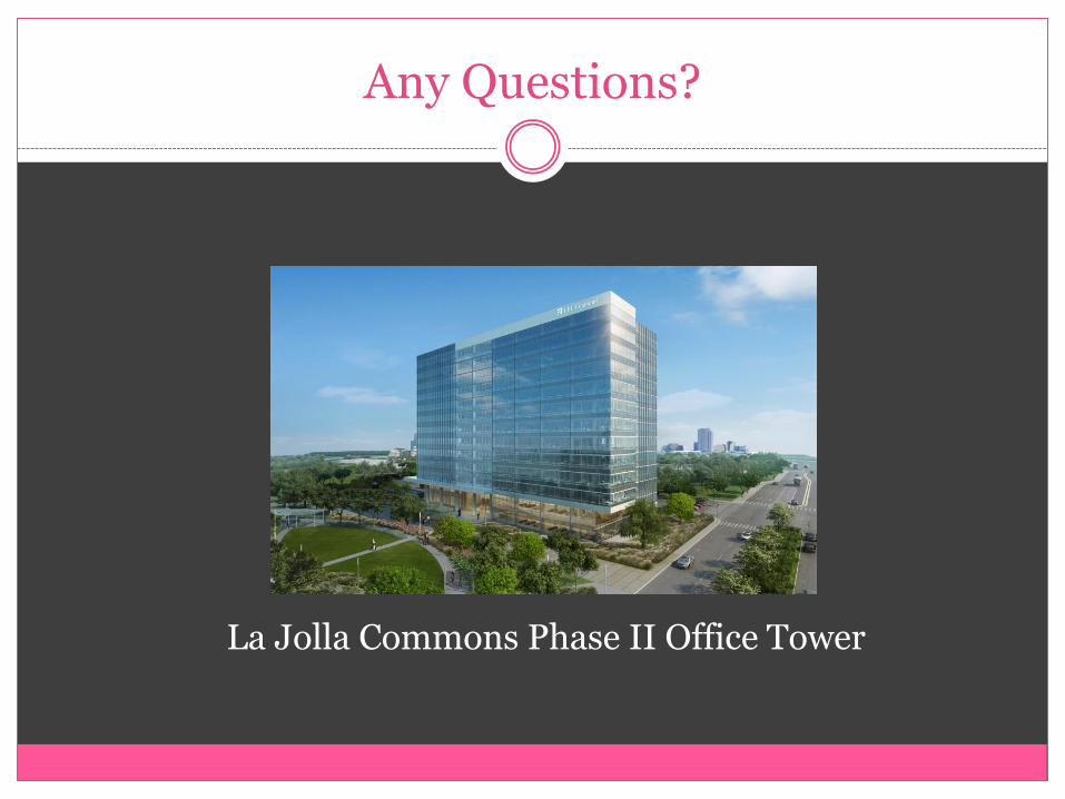
Any Questions?
La Jolla Commons Phase II Office Tower