Embed Size (px)
Citation preview

Alum
inum Po
le S
ele
ction G
uide

Continually Improving Our Customers’ Experience
Feralux and West Coast Engineering are trusted brands in the Canadian lighting and transportation markets. Building on this strong heritage of proven results, our Canadian customers can now benefit by leveraging the worldwide technical resources of Valmont Industries. With four manufacturing facilities in Canada, eight more in the US, and facilities in Europe, Asia and Australia; we know of no other Canadian light pole manufacturer equaling our unique combination of global resources and local expertise.
This aluminum pole selection guide (PSG) enables our valued customers across Canada to easily tap into our comprehensive selection of products and technical solutions. The PSG provides a superb overview of standard products engineered to meet the Canadian Bridge Design Code and relevant CSA guidelines.
Standing behind this Valmont offering are people possessing an uncompromising passion for quality, service and innovation. Our talented professionals are truly interested in continually improving our customers’ experience day after day, year after year.
For further details regarding the aluminum product offering presented in this selection guide, please contact our local sales professionals in Delta, British Columbia; Barrie, Ontario, or Ste-Julie, Quebec.
A c r o S S c A n A d A
3

INTRODUCTION..............................................................................................3
GlOssaRy .....................................................................................................5
ROUND TaPERED aNCHOR BasE POlEs ........................................................ 6-9
8’ - 18’ .......................................................................................................7
20’ - 28’ .....................................................................................................8
30’ - 50’ .....................................................................................................9
ROUND TaPERED EMBEDDED POlEs .......................................................... 10-11
8’ - 30’ .....................................................................................................11
aRMs ..................................................................................................... 12-15
TrUSS ................................................................................................. 12-13
clamp ...................................................................................................12
Bolt-on ...................................................................................................13
ELLIPTIcAL ............................................................................................ 14-15
clamp ...................................................................................................14
Bolt-on ...................................................................................................14
Simplex ..................................................................................................15
Hub .......................................................................................................15
DavITs ................................................................................................... 16-19
20’ - 40’ Single ..................................................................................... 16-17
20’ - 40’ double .................................................................................... 18-19
TRaffIC .................................................................................................. 20-23
4’ - 22’ SMA ..............................................................................................21
19’ SMA ...................................................................................................21
8’ - 15’ rT Post-Top ......................................................................................21
13’ - 19’ Truss Arms ................................................................................ 22-23
sqUaRE sTRaIGHT POlEs ........................................................................ 24-25
8’ - 35’ ......................................................................................................25
sqUaRE sTRaIGHT CRUCIfORM POlEs ...........................................................25
8’ - 25’ .....................................................................................................25
ROUND sTRaIGHT POlEs ......................................................................... 26-27
8’ - 14’ ......................................................................................................27
16’ - 25’ ....................................................................................................29
ROUND sTRaIGHT HINGED POlEs ......................................................................
8’ - 20’ ......................................................................................................30
ROUND TaPERED HINGED POlEs .......................................................................
8’ - 20’ ......................................................................................................31
DECORaTIvE ........................................................................................... 32-33
Fluted overview ...........................................................................................33
ROUND TaPERED IDylINE POlEs ............................................................... 34-35
curve .........................................................................................................35
Sigma ........................................................................................................35
sPECIfICaTIONs ...........................................................................................36
COaTINGs ...................................................................................................37
DEsIGN sTaNDaRDs ............................................................................... 38-40
WIND PREssURE fORCEs MaP .......................................................................41
NOTEs ................................................................................................... 42-43
4 A L U M I n U M P o L E S E L E c T I o n G U I d E
T A B L E O F C O N T E N T S

5
G L O S S A R Y
ABD; Anchor Bolt DiameterOD; Outside DiameterAnchor Bolts; Bolts used to secure the pole to the foundationBanner Arms; Accessory for mounting banners on polesBase Cover; Made of aluminum or plastic to encase the base plate of the poleBase Casting; The casting attached to the bottom of the pole, providing a means for anchoringBCD; Bolt Circle Diameter - bolt center to center distance on the diagonalBollard; A decorative post used as a pedestrian or traffic barrier. Sometimes strung with chainsBSQ; Bolt Square - bolt center to center distance on squareCapital; Ornamental pole topDavit; Top portion of a pole which is radiused to extend from the center of the main shaftDD; Double Davit pole with two armsEPA; Effective Projected Area - expressed in ft2 or m2
Flange Plate; Connection plate between two pole sections or bottom pole and armsFluted; A decorative pole cross sectionGround Stud; A bolt attached to the inside of the hand hole providing the means of electrical groundingHSS; Hollow Structure SectionJunction Box; In-ground plastic wiring enclosuresLadder Bar; An ornamental tenon with provision for resting a ladderLuminaire; Fixture or lamp mounted on poleNut Covers; Covers for anchor bolt nutsSD; Single Davit pole with one armSquare; Cross-section consisting of 4 equal sidesTapered; A constant reduction of diameter over the length of the poleTenon; Pipe welded to the pole for mounting fixtures
Catalogue Number Logic
a-RT-30-0.188a-x.x
AlumiumMaterial
PoleType
PoleHeight
ShaftThickness
Pole FixtureOptions Code
(See Table)
SurfaceFinishCode
(See Table)
6 A L U M I n U M P o L E S E L E c T I o n G U I d E
8 ’ T O 5 0 ’ A L u m i N u m R O u N D T A P E R E D
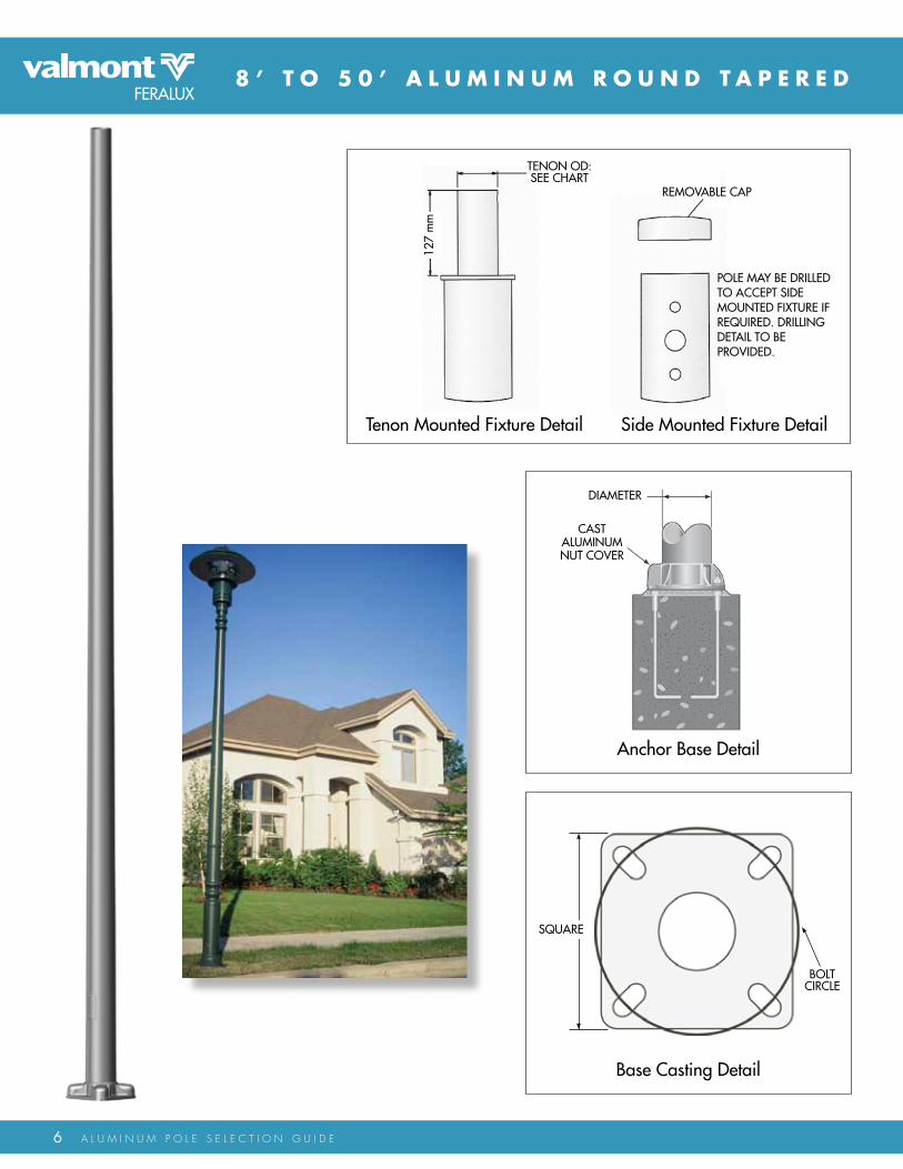
Base Casting Detail
sqUaRE
BOlT CIRClE
anchor Base Detail
DIaMETER
CasT alUMINUM NUT COvER
Tenon Mounted fixture Detail side Mounted fixture Detail
REMOvaBlE CaP
POlE May BE DRIllED TO aCCEPT sIDE MOUNTED fIXTURE If REqUIRED. DRIllING DETaIl TO BE PROvIDED.
127
mm
TENON OD: sEE CHaRT

aluminum Round Tapered Poles - 8’ to 18’
7
Satin Brushed00
duranodic02
Powder coat03
Special request04
Surface Finish CodesSuffix X.X Description
Pole Fixture Options Chart
Top cap only0.00.10.2
0.30.42.0
2.53.0
4.03.5
Top cap with one side-mounted fixtureTop cap with two side-mounted fixturesTop cap with three side-mounted fixturesTop cap with four side-mounted fixturesTop tenon, 60mm o.d.
Top tenon, 73mm o.d.Top tenon, 89mm o.d.Top tenon, 102mm o.d.Top tenon, 114mm o.d.
4 - B O L T A N C H O R B A S E P O L E S
0.34
q<=7
50Pa
0.04
q<=8
30Pa
CatalogueNumber max. EPA (m2)
Hei
ght
Base Casting Anchor Bolt
Pole
Con
figur
atio
n
Wei
ght (
Kg)
sq (m
m)
BCD
Min
. (m
m)
aB
Diam
eter
(in)
Proj
ectio
n(s
him
lvl.)
(mm
)
Proj
ectio
n(N
ut lv
l.) (m
m)
aB
leng
th (i
n)
q<=3
60Pa
q<=4
10Pa
q<=4
60Pa
q<=5
60Pa
q<=6
50Pa
Shaft
Base
OD
(mm
)
Top
OD
(mm
)
BCD
(mm
)
BCD
Max
. (m
m)
8’
12’
16’
18’
A-rT-8-0.125-x.x 0.758 222 165 24 83 127 0.82 0.71 0.62 0.49 0.41102 76 187 210A-rT-10-0.125A-x.x
A-rT-10-0.125B-x.x
A-rT-12-0.125A-x.xA-rT-12-0.125B-x.xA-rT-12-0.156-x.xA-rT-12-0.188-x.x
10’
14’
A-rT-14-0.125A-x.xA-rT-14-0.125B-x.xA-rT-14-0.156-x.xA-rT-14-0.188-x.x
A-rT-16-0.156A-x.xA-rT-16-0.188A-x.xA-rT-16-0.156B-x.xA-rT-16-0.188B-x.x
A-rT-16-0.125B-x.x
A-rT-18-0.188A-x.xA-rT-18-0.156B-x.xA-rT-18-0.188B-x.xA-rT-18-0.156c-x.x
A-rT-18-0.156A-x.x
101111
13
15
18
102127102
127
127
127
767676
76
76
76
222235222
235
235
235
165191165
191
191
191
187216187
216
216
216
210241210
241
241
241
0.750.750.75
0.75
0.75
0.75
24 83 12724 83 127
24 83 127
24 83 12724 83 12724 83 127
0.631.050.49
0.84
1.07
1.31
0.540.900.41
0.71
0.92
1.13
0.460.790.34
0.62
0.80
0.99
0.520.29
0.430.23
0.20
0.380.510.65
0.15
0.310.420.54
0.040.040.04
0.04
0.04
0.04
0.360.620.25
0.480.630.78
13
15
17
20
102
127
127
127
76
76
76
76
222
235
235
235
165
191
191
191
187
216
216
216
210
241
241
241
0.75
0.75
0.75
0.75
24 83 127
24 83 12724 83 12724 83 127
0.37
0.67
0.88
1.09
0.30
0.57
0.74
0.93
0.25
0.48
0.64
0.80
0.12
0.280.390.51
0.08
0.210.310.41
0.04
0.04
0.04
0.04
0.17
0.360.490.62
16
19
23
2429
127
127
127
152152
76
76
76
102102
235
235
235
260260
191
191
191
222222
216
216
216
241241
241
241
241
260260
0.75
0.75
0.75
0.750.75
24 89 13324 89 133
24 83 127
24 83 12724 83 127
0.54
0.72
0.90
1.091.35
0.44
0.60
0.76
0.911.15
0.37
0.51
0.65
0.780.99
0.19
0.29
0.46
0.13
0.22
0.36
0.04
0.04
0.04
0.040.04
0.26
0.370.490.58
0.76 0.61 0.49
0.39 0.31
22
25
2732
30
127
127
152152
178
76
76
102102
102
235
235
260260
284
191
191
222222
254
216
216
241241
267
241
241
260260
279
0.75
0.75
0.750.75
124 89 13336 105 169
24 83 127
24 83 12724 89 133
0.52
0.75
0.90
1.141.35
0.42
0.63
0.74
0.961.14
0.34
0.53
0.62
0.810.97
0.15
0.29
0.47
0.09
0.21
0.36
0.04
0.04
0.04
0.040.04
0.22
0.380.450.61
0.73 0.59 0.47
0.34 0.25
Dimensions shown in tables are nominal. Please consult factory drawings and calculations and consider subtle variations given manufacturing standards.
8 A L U M I n U M P o L E S E L E c T I o n G U I d E
8 ’ T O 5 0 ’ A L u m i N u m R O u N D TA P E R E D
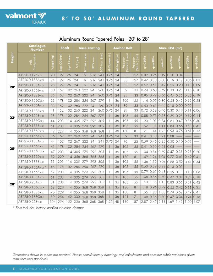
Dimensions shown in tables are nominal. Please consult factory drawings and calculations and consider subtle variations given manufacturing standards.
* Pole includes factory installed vibration damper.
aluminum Round Tapered Poles - 20’ to 28’
---------
q<=7
50Pa
---------
q<=8
30Pa
CatalogueNumber max. EPA (m2)
Hei
ght
Base Casting Anchor Bolt
Pole
Con
figur
atio
n
Wei
ght (
Kg)
sq (m
m)
BCD
Min
. (m
m)
aB
Diam
eter
(in)
Proj
ectio
n(s
him
lvl.)
(mm
)
Proj
ectio
n(N
ut lv
l.) (m
m)
aB
leng
th (i
n)
q<=3
60Pa
q<=4
10Pa
q<=4
60Pa
q<=5
60Pa
q<=6
50Pa
Shaft
Base
OD
(mm
)
Top
OD
(mm
)
BCD
(mm
)
BCD
Max
. (m
m)
25’
28’
A-rT-20-0.125-x.x 0.7520 241 191 24 83 127 0.32 0.25 0.19 0.10 0.04127 76 216 241A-rT-20-0.156A-x.x
A-rT-20-0.188A-x.x
A-rT-20-0.156B-x.xA-rT-20-0.188B-x.xA-rT-20-0.156c-x.xA-rT-23-0.156A-x.x
20’
23’
A-rT-23-0.188A-x.xA-rT-23-0.156B-x.xA-rT-23-0.156c-x.xA-rT-23-0.188B-x.x
A-rT-25-0.188A-x.xA-rT-25-0.156B-x.xA-rT-25-0.156c-x.x
A-rT-25-0.188B-x.x
A-rT-25-0.156A-x.x
A-rT-28-0.156B-x.x
A-rT-28-0.188A-x.xA-rT-28-0.25A-x.xA-rT-28-0.156c-x.x
A-rT-28-0.156A-x.x*
242830
35
33
33
127127152
152
178
152
7676102
102
102
102
241241260
260
284
260
191191222
222
254
222
216216241
241
267
241
241241260
260
279
260
0.750.750.75
0.75
1
0.75
24 83 12724 83 127
24 89 133
24 89 13336 105 15524 89 133
0.470.620.74
0.95
1.14
0.53
0.380.510.60
0.79
0.95
0.41
0.300.420.49
0.66
0.80
0.32
0.200.12
0.130.06
0.23
0.350.450.09
0.15
0.250.350.02
0.030.090.10
0.19
0.28
---------
0.190.290.33
0.470.580.18
41
38
44
51
49
152
178
203
203
229
102
102
114
114
114
260
284
305
305
356
222
254
279
279
368
241
267
292
292
368
260
279
305
305
368
0.75
1
1
1
1
24 89 133
36 105 15536 105 15536 105 155
0.72
0.88
1.23
1.571.71
0.58
0.71
1.01
1.311.44
0.46
0.58
0.84
1.111.23
0.19
0.280.470.66
0.11
0.190.360.53
0.06
0.14
0.30
0.450.53
0.30
0.390.610.83
36
44
41
475255
152
152
178
203229203
102
102
102
114114114
260
260
284
305356305
222
222
254
279368279
241
241
267
292368292
241
241
279
305368305
0.75
0.75
1
1
11
36 105 155
36 105 155
24 89 133
24 89 13336 105 155
0.41
0.59
0.41
1.041.49
0.30
0.46
0.30
0.841.24
0.21
0.35
0.21
0.691.04
---------
0.10
0.35
---------
0.02
0.25
---------
---------
---------
0.200.41
0.08
0.200.080.47
0.68 0.52 0.41
--------- ---------
46
52
6181
5870
178
203
203203
229229
102
114
114114
114114
284
305
305305
356356
254
279
279279
368368368368
267
292
292292
368368368368
279
305
305305
368368
1
1
11
11
36 105 1553636
130 181
36 105 155
36 105 155
36 105 155
0.53
0.79
1.08
1.63
1.18
0.39
0.61
0.86
1.35
0.96
0.28
0.48
0.70
1.13
0.79
---------
0.06
0.18
0.420.25
0.13
0.290.470.83
0.55 0.42 0.31
0.03
0.18
0.650.34
---------
0.10
0.510.24
A-rT-28-0.188B-x.x 181130 1.55 1.28 1.08 0.79 0.62 0.49 0.41
A-rT-23-0.156d-x.x 36 181130 0.75 0.610.93
A-rT-25-0.156d-x.x 36 130 1811.36 1.12 0.94 0.34
0.61 0.490.77
A-rT-28-0.188c-x.x 80104
254254
152152
330356
368368
11.25
3648
121 171 0.47 0.34 0.24A-rT-28-0.25B-x.x 187130 2.87 2.45 2.13 1.69 1.42 1.20 1.07
1.08 0.86 0.70 0.18

9
4 - B O L T A N C H O R B A S E P O L E S
aluminum Round Tapered Poles - 30’ to 50’
Alternate heights and loadings may be considered in the proper applications. Please contact the factory for poles not on the PSG list.
--------
q<=7
50Pa
--------
q<=8
30Pa
CatalogueNumber max. EPA (m2)
Hei
ght
Base Casting Anchor Bolt
Pole
Con
figur
atio
n
Wei
ght (
Kg)
sq (m
m)
BCD
Min
. (m
m)
aB
Diam
eter
(in)
Proj
ectio
n(s
him
lvl.)
(mm
)
Proj
ectio
n(N
ut lv
l.) (m
m)
aB
leng
th (i
n)
q<=3
60Pa
q<=4
10Pa
q<=4
60Pa
q<=5
60Pa
q<=6
50Pa
Shaft
Base
OD
(mm
)
Top
OD
(mm
)
BCD
(mm
)
BCD
Max
. (m
m)
30’
35’
39’
48’
A-rT-30-0.156B-x.x* 155 305 279 36 105 155 0.65 0.48 0.35 0.18 0.08203 114 292 305A-rT-30-0.188A-x.x
A-rT-30-0.25A-x.x
A-rT-30-0.156c-x.x
A-rT-30-0.25B-x.x
A-rT-33-0.188A-x.xA-rT-33-0.25A-x.x
33’
37’
A-rT-33-0.188B-x.xA-rT-33-0.188c-x.xA-rT-33-0.25B-x.x
A-rT-35-0.156A-x.x*
A-rT-35-0.25A-x.xA-rT-35-0.156B-x.x*A-rT-35-0.188B-x.x
A-rT-35-0.188A-x.x
A-rT-37-0.188A-x.x*A-rT-35-0.25B-x.x
658661
74
85
111
203203229
229
254
254
114114114
114
152
152
305305356
356
330
330
279279368
368
368
368
292292368
368
368
368
305305368
368
368
368
111
1
1
1
36 105 15536 105 155
36 114 165
36 105 15536 105 15536 105 155
0.911.431.01
1.36
1.73
2.57
0.711.170.80
1.11
1.44
2.18
0.560.970.65
0.92
1.23
1.88
0.520.23
0.390.14
0.30
0.500.771.24
0.21
0.380.641.04
0.090.320.16
0.31
0.56
0.92
0.350.680.43
0.650.941.48
81
92
119
63
229
254
254
203
114
152
152
114
356
330
330
305
368
368
368
279
368
368
368
292
368
368
368
305
1
1
1
1
36 114 165
36 114 16536 121 17136 121 171
0.77
1.09
1.40
2.17
0.58
0.86
1.14
1.82
0.44
0.69
0.96
1.56
0.14
0.320.571.00
0.07
0.220.460.83
0.02
0.16
0.40
0.73
0.25
0.460.711.20
77
99
72
85
203
203
229
229
114
114
114
114
305
305
356
356
279
279
368
368
292
292
368
368
305
305
368
368
1
1
1
136 114 16536 114 165
36 105 155
36 105 15536 105 155
0.32
0.55
0.99
0.620.91
0.18
0.38
0.77
0.440.70
0.07
0.25
0.60
0.310.55
--------
--------
0.04
--------
--------
--------
--------
--------
0.08
--------0.07
--------
0.080.360.14
0.33 0.21 0.12
0.23 0.13
128
79
254
203
152
114
330
305
368
279
368
292
368
305
1
136 121 171 1.90 1.58 1.34 0.84 0.69 0.601.03
A-rT-30-0.156A-x.x* 149 254 36102 286270284178 105 155 0.41 0.28 0.18 0.03 --------
0.01 --------
36 121 171
36 121 17136 114 165A-rT-30-0.188B-x.x
A-rT-30-0.188c-x.x
A-rT-33-0.156A-x.x* 60
71
94
66
203
203
203
229
114
114
114
114
305
305
305
356
279
279
279
368
292
292
292
368
305
305
305
368
1
1
1
1A-rT-33-0.156B-x.x*
0.45
0.69
1.16
0.29
0.51
0.92
0.18
0.37
0.74
--------
0.080.34
--------
--------0.23
--------
--------
0.17
0.03
0.180.49
50’
36 105 155 0.42
0.83
0.26
0.62
0.14
0.46
--------0.12
--------0.03
--------
--------
--------0.25
A-rT-37-0.156-x.x*A-rT-37-0.25A-x.x 104
76
203
229
114
114
305
356
279
368
292
368
305
368
1
1
36 105 15536 114 165 0.48
0.760.320.56
0.200.41
--------0.11
--------0.03
--------
--------0.040.22A-rT-37-0.188B-x.x*
A-rT-37-0.25B-x.xA-rT-37-0.188c-x.x
89
102
229
254
114
152
356
330
368
368
368
368
368
368
1
136 114 16536 121 171
135
84
254
203
152
114
330
305
368
279
368
292
368
305
1
136 121 17136 105 155
0.99
1.67
0.78
1.37
0.62
1.15
0.33
0.70
0.250.57
0.20
0.49
0.43
0.860.290.68
0.140.49
0.030.34
--------0.02
----------------
----------------
--------0.14
A-rT-39-0.188A-x.x*
A-rT-39-0.156-x.x*A-rT-39-0.25A-x.x
A-rT-39-0.188B-x.x*
A-rT-39-0.25B-x.xA-rT-39-0.188c-x.x
A-rT-50-0.25-x.xA-rT-48-0.25-x.x
110
79
203
229
114
114
305
356
279
368
292
368
305
368
1
194
107
229
254
114
152
356
330
368
368
368
368
368
368
1
1141
171
254
254
152
152
330
330
368
368
368
368
368
368
1
1180 254 152 356 368 368 368 1.25
36 105 15536 114 16536 114 16536 121 17136 121 17136 121 17154 133 190
0.35
0.61
0.20
0.43
0.09
0.29
--------
0.01
--------
0.110.811.45
0.621.17
0.480.97
0.220.57
0.310.71
0.630.48
0.440.30
0.300.18
0.08--------
0.160.05
----------------
----------------
0.110.15
--------0.020.380.45
----------------
* Pole includes factory installed vibration damper.

10 A L U M I n U M P o L E S E L E c T I o n G U I d E
8 ’ - 3 0 ’ A L u m i N u m R O u N D TA P E R E D
anchor Base & Bolt Detail
DIaMETER
WIRE aCCEss
EMBEDDED lENGTH
Tenon Mounted fixture Detail side Mounted fixture Detail
REMOvaBlE CaP
POlE May BE DRIllED TO aCCEPT sIDE MOUNTED fIXTURE If REqUIRED. DRIllING DETaIl TO BE PROvIDED.
127
mm
TENON OD: sEE CHaRT
* Wire access hole provided as standard on embedded designs.

11
Satin Brushed00
duranodic02
Powder coat03
Special request04
Surface Finish CodesSuffix X.X Description
Pole Fixture Options Chart
Top cap only0.00.10.2
0.30.42.0
2.53.0
4.03.5
Top cap with one side-mounted fixtureTop cap with two side-mounted fixturesTop cap with three side-mounted fixturesTop cap with four side-mounted fixturesTop tenon, 60mm o.d.
Top tenon, 73mm o.d.Top tenon, 89mm o.d.Top tenon, 102mm o.d.Top tenon, 114mm o.d.
E m B E D D E D P O L E S
Alternate heights and loadings may be considered in the proper applications. Please consult the factory regarding recommended embedded depth and for mounting heights not listed.
aluminum Round Tapered Embedded Poles - 8’ to 30’CatalogueNumber
mou
ntin
g H
eight
(Ove
rall
heig
ht =
5’)
Pole
Con
figur
atio
n
Wei
ght (
Kg)
Shaft
Base
OD
(mm
)
Top
OD
(mm
)
8’
18’
25’
30’
A-rT-E-8-0.125-x.x 6 102 76A-rT-E-10-0.125-x.x
A-rT-E-12-0.125A-x.x
A-rT-E-12-0.125B-x.xA-rT-E-14-0.125A-x.xA-rT-E-14-0.125B-x.xA-rT-E-16-0.125B-x.x
16’
20’
A-rT-E-16-0.156-x.xA-rT-E-18-0.156A-x.xA-rT-E-18-0.156B-x.xA-rT-E-20-0.156-x.x
A-rT-E-25-0.188-x.xA-rT-E-30-0.156A-x.x
A-rT-E-25-0.156-x.x
7910
10
12
13
102102127
102
127
127
767676
76
76
7617
19
23
21
127
127
152
127
76
76
102
7633
39
49
152
152
203
102
102
114
0.24q<
=750
Pa0.20
q<=8
30Pa
max. EPA (m2)
q<=3
60Pa
q<=4
10Pa
q<=4
60Pa
q<=5
60Pa
q<=6
50Pa
0.65 0.55 0.48 0.37 0.290.500.380.62
0.29
0.50
0.40
0.420.310.52
0.22
0.41
0.32
0.350.260.44
0.17
0.34
0.25
0.120.20
0.080.15
0.25
0.050.170.09
0.19
0.010.110.04
0.120.050.15
0.00
0.07
0.01
0.260.170.32
0.100.230.15
0.55
0.45
0.72
0.35
0.45
0.36
0.60
0.27
0.37
0.28
0.50
0.20
0.18
0.110.250.04
0.12
0.050.17--------
0.08
0.01
0.12
--------
0.26
0.180.350.10
0.36
0.51
0.52
0.26
0.39
0.36
0.18
0.30
0.24
--------
0.08
--------
-------
--------
--------
--------
0.06
0.160.07 -------- --------
10’
12’
14’
Dimensions shown in tables are nominal. Please consult factory drawings and calculations and consider subtle variations given manufacturing standards.

12 A L U M I n U M P o L E S E L E c T I o n G U I d E
6’ - 15’ ALumiNum CLAmP-ON TRuSS ARmS
single Truss arm
Double Truss arm
Clamp mount: Clamp mounted truss arms are held in place by pairs of matching aluminum extrusions. Two extrusions are welded to the end of the truss members and the others are placed on the opposite side of the lighting standard. The connection is secured with stainless steel bolts and hardware. Clamp mounted truss arms fit 4”, 4 ½”, and 6” diameter pole tops.

13
6’ - 15’ ALumiNum BOLT-ON TRuSS ARmS
single Truss arm
Double Truss arm
Bolt mount: Bolt mounted truss arms are held in place with stainless steel bolts and hardware. The lighting standard is pre-drilled to accept the hardware. Bolt mount truss arms fit 4”, 4 ½”, and 6” diameter pole tops.
Please contact the factory for suggested pole sizes required to achieve luminaire mounting heights.

14 A L U M I n U M P o L E S E L E c T I o n G U I d E
4’, 6’ AND 8’ TAPERED CLAmP-ON ELLiPTiCAL mAST ARmS
Bolt mount: Bolt mounted mast arms are held in place with stainless steel bolts and hardware. The lighting standard is pre-drilled to accept the hardware. Bolt mount arms fit 4”, 4 ½”, and 6” diameter pole tops.
Center line of Pole
span
Rise
Clamp mount: Clamp mounted mast arms are held in place by a pair of matching aluminum extrusions. One extrusion is welded to the end of the mast arm and the second is placed on the opposite side of the lighting standard. The connection is secured with stainless steel bolts and hardware.
Center line of Pole
span
Rise
4’, 6’ AND 8’ TAPERED BOLT mOuNT ELLiPTiCAL mAST ARmS

15
4’, 6’ AND 8’ TAPERED SimPLEX mOuNT ELLiPTiCAL mAST ARmS
4’, 6’ AND 8’ TAPERED HuB mOuNT ELLiPTiCAL mAST ARmS
Simplex mount: Simplex mounted mast arms are held in place by a pair of interlocking aluminum castings. One is welded to the lighting standard and the second is welded to the end of the mast arm. The connection is secured with stainless steel bolts and hardware. Simplex arms fit 4”, 4 ½”, and 6” diameter pole tops.
Hub mount: Hub mounted mast arms are held in place with (3) stainless steel screws. The arm can be oriented in any direction at the time of installation. Hub mounted arms fit 3”, 4”, 4 ½”, and 6” diameter pole tops.
Center line of Pole
span
Rise
Center line of Pole
span
Rise
Please contact the factory for suggested pole sizes required to achieve luminaire mounting heights.

16 A L U M I n U M P o L E S E L E c T I o n G U I d E
20‘ - 40’ SiNGLE DAViT ROuND TAPERED POLES
aluminum 4’ - arm Reach - 20’ - 40’ Mounting Height
0.29
q<=7
50Pa
0.23
q<=8
30Pa
CatalogueNumber max. EPA (m2)
Hei
ght
Base Casting Anchor Bolt
Pole
Con
figur
atio
n
Wei
ght (
Kg)
sq (m
m)
BCD
Min
. (m
m)
aB
Diam
eter
(in)
Proj
ectio
n(s
him
lvl.)
(mm
)
Proj
ectio
n(N
ut lv
l.) (m
m)
aB
leng
th (i
n)
q<=3
60Pa
q<=4
10Pa
q<=4
60Pa
q<=5
60Pa
q<=6
50Pa
Shaft
Base
OD
(mm
)
Top
OD
(mm
)
BCD
(mm
)
BCD
Max
. (m
m)
20’
30’
40’
A-Sd-20-04-0.156-x.x 0.7525 260 222 24 89 133 1.08 0.89 0.79 0.54 0.40152 70 241 260A-Sd-25-04-0.156B-x.x
A-Sd-30-04-0.156c-x.x
A-Sd-35-04-0.25-x.xA-Sd-40-04-0.25-x.x
25’
35’
344477
87
178203203
203
707070
70
259305305
305
254279
279
279
267292
292
292
279305
305
305
111
1
36 105 15536 105 155
36 105 155
36 105 155
0.500.440.71
0.39
0.370.300.53
0.24
0.270.200.39
0.12
--------0.03
----------------
0.07
--------
--------
--------
------------------------
--------
0.120.040.19
--------
single Davit arm
anchor Base Detail
CasT alUMINUM NUT COvER
HaNDHOlE DOOR
Handhole Detail
BOlT CIRClE
sqUaRE

17
20‘ - 40’ SiNGLE DAViT ROuND TAPERED POLES
aluminum 6’ - arm Reach - 20’ - 40’ Mounting Height
--------
q<=7
50Pa
--------
q<=8
30Pa
CatalogueNumber max. EPA (m2)
Hei
ght
Base Casting Anchor Bolt
Pole
Con
figur
atio
n
Wei
ght (
Kg)
sq (m
m)
BCD
Min
. (m
m)
aB
Diam
eter
(in)
Proj
ectio
n(s
him
lvl.)
(mm
)
Proj
ectio
n(N
ut lv
l.) (m
m)
aB
leng
th (i
n)
q<=3
60Pa
q<=4
10Pa
q<=4
60Pa
q<=5
60Pa
q<=6
50Pa
Shaft
Base
OD
(mm
)
Top
OD
(mm
)
BCD
(mm
)
BCD
Max
. (m
m)
20’
30’
40’
A-Sd-20-06-0.156-x.x 0.7527 260 222 24 89 133 0.46 0.34 0.25 0.11 0.02152 70 241 260A-Sd-25-06-0.156B-x.x
A-Sd-30-06-0.156c-x.x
A-Sd-35-06-0.25-x.xA-Sd-40-06-0.25-x.x
25’
35’
374781
92
178203203
203
707070
70
259305305
305
254279
279
279
267292
292
292
279305
305
305
111
1
36 105 15536 105 155
36 105 155
36 105 155
0.420.360.63
0.31
0.290.220.45
0.16
0.190.110.31
0.04
----------------
----------------
--------
--------
--------
--------
------------------------
--------
0.04--------
0.11
--------
aluminum 8’ - arm Reach - 20’ - 40’ Mounting Height
--------
q<=7
50Pa
--------
q<=8
30Pa
CatalogueNumber max. EPA (m2)
Hei
ght
Base Casting Anchor Bolt
Pole
Con
figur
atio
n
Wei
ght (
Kg)
sq (m
m)
BCD
Min
. (m
m)
aB
Diam
eter
(in)
Proj
ectio
n(s
him
lvl.)
(mm
)
Proj
ectio
n(N
ut lv
l.) (m
m)
aB
leng
th (i
n)
q<=3
60Pa
q<=4
10Pa
q<=4
60Pa
q<=5
60Pa
q<=6
50Pa
Shaft
Base
OD
(mm
)
Top
OD
(mm
)
BCD
(mm
)
BCD
Max
. (m
m)
20’
30’
40’
A-Sd-20-08-0.156-x.x 0.7529 260 222 24 89 133 0.38 0.26 0.17 0.02 --------152 70 241 260A-Sd-20-08-0.188-x.x
A-Sd-30-08-0.188-x.x
A-Sd-35-08-0.25-x.x
A-Sd-40-08-0.188B-x.x
25’
35’
343958
85
152178203
203
707070
70
260284305
305
222254
279
279
241267
292
292
260279
305
305
0.7511
1
36 105 15524 89 133
36 105 155
36 105 155
0.570.340.50
0.55
0.430.210.34
0.37
0.320.110.21
0.23
--------0.05
----------------
--------
--------
--------
--------
------------------------
--------
0.16--------
0.02
0.02
A-Sd-25-08-0.156B-x.x
85 330 368254 70 1368 368 -------- --------36 121 171 0.42 0.25 0.12 -------- --------
aluminum 10’ - arm Reach - 25’ - 40’ Mounting Height
q<=7
50Pa
q<=8
30Pa
CatalogueNumber max. EPA (m2)
Hei
ght
Base Casting Anchor Bolt
Pole
Con
figur
atio
n
Wei
ght (
Kg)
sq (m
m)
BCD
Min
. (m
m)
aB
Diam
eter
(in)
Proj
ectio
n(s
him
lvl.)
(mm
)
Proj
ectio
n(N
ut lv
l.) (m
m)
aB
leng
th (i
n)
q<=3
60Pa
q<=4
10Pa
q<=4
60Pa
q<=5
60Pa
q<=6
50Pa
Shaft
Base
OD
(mm
)
Top
OD
(mm
)
BCD
(mm
)
BCD
Max
. (m
m)
30’
40’
A-Sd-25-10-0.156c-x.x
A-Sd-35-10-0.25-x.x
A-Sd-30-10-0.188-x.x
A-Sd-40-10-0.188B-x.x
25’
35’
4662
90
93
203203
203
254
7070
70
70
305305
305
330
279279279
368
292292292
368
305305305
368
111
1
36 105 15536 105 155
36 105 155
36 121 171
0.540.420.46
0.29
0.370.250.28
0.12
0.240.120.14
---------
----------------
----------------
--------
--------
--------
--------
------------------------
--------
0.05----------------
--------
Alternate heights and loadings may be considered in the proper applications. Please contact the factory for poles not on the PSG list.
Dimensions shown in tables are nominal. Please consult factory drawings and calculations and consider subtle variations given manufacturing standards.
Please contact the factory for suggested pole sizes required to achieve luminaire mounting heights.

18 A L U M I n U M P o L E S E L E c T I o n G U I d E
20‘ - 40’ DOuBLE DAViT ROuND TAPERED POLES
Double Davit arm
anchor Base Detail
CasT alUMINUM NUT COvER
HaNDHOlE DOOR
Handhole Detail
BOlT CIRClE
sqUaRE
aluminum 4’ - arm Reach - 20’ - 40’ Mounting Height
--------
q<=7
50Pa
--------
q<=8
30Pa
CatalogueNumber max. EPA (m2)
Hei
ght
Base Casting Anchor Bolt
Pole
Con
figur
atio
n
Wei
ght (
Kg)
sq (m
m)
BCD
Min
. (m
m)
aB
Diam
eter
(in)
Proj
ectio
n(s
him
lvl.)
(mm
)
Proj
ectio
n(N
ut lv
l.) (m
m)
aB
leng
th (i
n)
q<=3
60Pa
q<=4
10Pa
q<=4
60Pa
q<=5
60Pa
q<=6
50Pa
Shaft
Base
OD
(mm
)
Top
OD
(mm
)
BCD
(mm
)
BCD
Max
. (m
m)
20’
30’
40’
A-dd-20-04-0.156A-x.x 0.7534 260 222 24 89 133 0.24 0.18 0.13 0.07 0.02152 70 241 260A-dd-20-04-0.156B-x.x
A-dd-30-04-0.156B-x.x
A-dd-35-04-0.25-x.xA-dd-40-04-0.25-x.x
25’
35’
374353
63
178178203
203
707070
70
259259305
305
254254
279
279
267267
292
292
279279
305
305
111
1
36 105 15536 105 155
36 105 155
36 105 155
0.410.220.19
0.31
0.330.160.12
0.22
0.260.110.07
0.16
--------0.11
--------0.06
--------
0.01
--------
--------
0.04----------------
--------
0.170.03--------
0.07
A-dd-25-04-0.156B-x.x
102 305 279203 70 1292 305 -------- --------36 105 155 0.17 0.09 0.03 -------- --------
A-dd-30-04-0.188-x.x91 305 279203 70 1292 305 -------- --------105 155 0.33 0.24 0.17 0.07 0.0136
Dimensions shown in tables are nominal. Please consult factory drawings and calculations and consider subtle variations given manufacturing standards.Please contact the factory for suggested pole sizes required to achieve luminaire mounting heights.

19
20‘ - 40’ DOuBLE DAViT ROuND TAPERED POLES
aluminum 6’ - arm Reach - 20’ - 40’ Mounting Height
0.02
q<=7
50Pa
--------
q<=8
30Pa
CatalogueNumber max. EPA (m2)
Hei
ght
Base Casting Anchor Bolt
Pole
Con
figur
atio
n
Wei
ght (
Kg)
sq (m
m)
BCD
Min
. (m
m)
aB
Diam
eter
(in)
Proj
ectio
n(s
him
lvl.)
(mm
)
Proj
ectio
n(N
ut lv
l.) (m
m)
aB
leng
th (i
n)
q<=3
60Pa
q<=4
10Pa
q<=4
60Pa
q<=5
60Pa
q<=6
50Pa
Shaft
Base
OD
(mm
)
Top
OD
(mm
)
BCD
(mm
)
BCD
Max
. (m
m)
20’
30’
40’
A-dd-20-06-0.156B-x.x 143 259 254 36 105 155 0.37 0.28 0.22 0.12 0.06178 70 267 279A-dd-25-06-0.156c-x.x
A-dd-30-06-0.25-x.x
A-dd-35-06-0.25-x.x
A-dd-40-06-0.25-x.x
25’
35’
537091
101
203203203
203
70700
70
305305305
305
279279
279
279
292292
292
292
305305
305
305
111
1
36 105 15536 105 155
36 105 155
36 105 155
0.320.480.48
0.28
0.230.370.37
0.19
0.170.280.28
0.12
0.090.02
0.03--------
0.09
--------
0.03
--------
------------------------
--------
0.080.160.16
0.02
A-dd-30-06-0.188-x.x
111 305 279203 70 1292 305 -------- --------36 105 155 0.12 0.04 -------- -------- --------
aluminum 8’ - arm Reach - 20’ - 40’ Mounting Height
--------
q<=7
50Pa
--------
q<=8
30Pa
CatalogueNumber max. EPA (m2)
Hei
ght
Base Casting Anchor Bolt
Pole
Con
figur
atio
n
Wei
ght (
Kg)
sq (m
m)
BCD
Min
. (m
m)
aB
Diam
eter
(in)
Proj
ectio
n(s
him
lvl.)
(mm
)
Proj
ectio
n(N
ut lv
l.) (m
m)
aB
leng
th (i
n)
q<=3
60Pa
q<=4
10Pa
q<=4
60Pa
q<=5
60Pa
q<=6
50Pa
Shaft
Base
OD
(mm
)
Top
OD
(mm
)
BCD
(mm
)
BCD
Max
. (m
m)
20’
30’
A-dd-20-08-0.156A-x.x 0.7548 260 222 24 89 133 0.13 0.07 0.02 -------- --------152 70 241 260A-dd-20-08-0.156B-x.x
A-dd-30-08-0.188-x.x
A-dd-35-08-0.25-x.xA-dd-35-08-0.188B-x.x
25’
35’
536382
106
178203203
203
707070
70
259305305
305
254279
279
279
267292
292
292
279305
305
305
111
1
36 105 15536 105 155
36 105 155
36 105 155
0.290.240.18
0.40
0.210.150.10
0.29
0.140.090.03
0.20
----------------
----------------
--------
0.01
--------
--------
------------------------
--------
0.05----------------
0.08
A-dd-25-08-0.156B-x.x
99 330 368254 70 1368 368 -------- --------36 121 171 0.34 0.23 0.15 0.04 --------
A-dd-30-08-0.25-x.x116 305 279203 70 1292 305 -------- --------105 155 0.20 0.11 0.04 -------- --------36
40’A-dd-40-08-0.188B-x.x 108 330 368254 70 1368 368 -------- --------36 121 171 0.15 0.06 -------- -------- --------
A-dd-40-08-0.25B-x.x 141 356 368254 70 1.25368 368 -------- --------48 133 190 0.40 0.28 0.19 0.07 --------
aluminum 10’ - arm Reach - 25’ - 40’ Mounting Height
Alternate heights and loadings may be considered in the proper applications. Please contact the factory for poles not on the PSG list.
--------
q<=7
50Pa
--------
q<=8
30Pa
CatalogueNumber max. EPA (m2)
Hei
ght
Base Casting Anchor Bolt
Pole
Con
figur
atio
n
Wei
ght (
Kg)
sq (m
m)
BCD
Min
. (m
m)
aB
Diam
eter
(in)
Proj
ectio
n(s
him
lvl.)
(mm
)
Proj
ectio
n(N
ut lv
l.) (m
m)
aB
leng
th (i
n)
q<=3
60Pa
q<=4
10Pa
q<=4
60Pa
q<=5
60Pa
q<=6
50Pa
Shaft
Base
OD
(mm
)
Top
OD
(mm
)
BCD
(mm
)
BCD
Max
. (m
m)
30’
A-dd-25-10-0.156B-x.x 170 305 279 36 105 155 0.19 0.10 0.03 -------- --------203 70 292 305A-dd-25-10-0.188-x.x
A-dd-30-10-0.25-x.x
A-dd-35-10-0.188B-x.x
25’
35’
8390117
126
203203203
203
707070
70
305305305
305
279279
279
279
292292
292
292
305305
305
305
111
1
36 105 15536 105 155
36 105 155
36 105 155
0.320.130.35
0.15
0.220.040.24
0.06
0.14--------
0.15
---------
----------------
----------------
--------
--------
--------
--------
------------------------
--------
0.03--------
0.03
--------
A-dd-30-10-0.188-x.x
A-dd-35-10-0.25-x.x110 330 368254 70 1368 368 -------- --------121 171 0.26 0.16 0.08 -------- --------36
40’ A-dd-40-10-0.25B-x.x 157 356 368254 70 1.25368 368 -------- --------133 190 0.33 0.21 0.12 -------- --------48

20 A L U M I n U M P o L E S E L E c T I o n G U I d E
4 ’ T O 2 2 ’ A L u m i N u m R O u N D
Dimensions shown in page 21 tables are nominal. Please consult factory drawings and calculations and consider subtle variations given manufacturing standards.

21
T A P E R E D T R A F F i C S m A A R m S
19’ - sMa arm Traffic Poles
--------
q<=7
50Pa
--------
q<=8
30Pa
CatalogueNumber max. EPA (m2)
Hei
ght
Base Casting Anchor Bolt
Pole
Con
figur
atio
n
Wei
ght (
Kg)
sq (m
m)
BCD
Min
. (m
m)
aB
Diam
eter
(in)
Proj
ectio
n(s
him
lvl.)
(mm
)
Proj
ectio
n(N
ut lv
l.) (m
m)
aB
leng
th (i
n)
q<=3
60Pa
q<=4
10Pa
q<=4
60Pa
q<=5
60Pa
q<=6
50Pa
Shaft
Base
OD
(mm
)
Top
OD
(mm
)
BCD
(mm
)
BCD
Max
. (m
m)
19’
A-rT-TSMA-19-0.188A-x.x 150 305 279 36 70 120 0.45 0.32 0.21 0.06 --------203 168 292 305A-rT-TSMA-19-0.25A-x.x
A-rT-TSMA-19-0.25B-x.x
646181
203254254
168203203
305330330
279330
330
292356
356
305381
381
111
36 76 12736 70 120
36 76 133
0.861.181.85
0.690.971.55
0.530.801.32
0.390.21
0.260.11
0.78 0.59
0.050.180.48
0.330.540.97
A-rT-TSMA-19-0.188B-x.x
Pole EPA rating calculated for a 22ft reach arm with the sign located at the tip of arm. For different arm reach or load configurations please contact factory.
Alternate heights and loadings may be considered in the proper applications. Please contact the factory for poles not on the PSG list.
1.257
q<=7
50Pa
1.13
q<=8
30Pa
CatalogueNumber max. EPA (m2)
Hei
ght
Base Casting
Pole
Con
figur
atio
n
sq (m
m)
BCD
Min
. (m
m)
q<=3
60Pa
q<=4
10Pa
q<=4
60Pa
q<=5
60Pa
q<=6
50Pa
Shaft
Base
OD
(mm
)
Top
OD
(mm
)
BCD
(mm
)
BCD
Max
. (m
m)
8’ A-rT-TPT-8-0.188-x.x 254 229 2.76 2.40 2.13 1.73 1.47152 114 241 254A-rT-TPT-10-0.188-x.x
A-rT-TPT-15-0.188-x.x
152152152
114114114
254254254
229229
229
241241
241
254254
254
2.221.831.39
1.931.531.18
1.701.381.02
0.911.15
0.760.98
0.64 0.52
0.870.670.45
1.371.100.79
A-rT-TPT-12-0.188-x.x
10’
12’
15’
8’ to 15’ - Round Tapered Post-Top Traffic Poles
0.76
q<=7
50Pa
0.68
q<=8
30Pa
CatalogueNumber max. EPA (m2)
Rea
chArm
arm
Con
figur
atio
n
Reac
h (m
)
Base
OD
(mm
)
Top
OD
(mm
)
q<=3
60Pa
q<=4
10Pa
q<=4
60Pa
q<=5
60Pa
q<=6
50Pa
Rise
(m)
Wei
ght (
Kg)
4’
8’
12’15’
A-rT-SMA-4-0.125-x.x 1.2 102 60 1.53 1.35 1.21 1.02 0.870.5 2.7A-rT-SMA-6-0.125-x.xA-rT-SMA-8-0.125-x.x
A-rT-SMA-10-0.125-x.xA-rT-SMA-12-0.125-x.xA-rT-SMA-15-0.156-x.xA-rT-SMA-18-0.188-x.x
6’
10’
A-rT-SMA-20-0.188-x.xA-rT-SMA-22-0.188-x.x
1.82.43.0
3.7
4.6
5.5
0.60.80.6
0.8
1.1
0.9
4.05.37.7
9.2
14.4
23.6
102102127
127
127
152
606060
60
60
60
0.940.640.79
0.59
0.50
0.74
0.830.550.69
0.50
0.42
0.63
0.740.490.60
0.44
0.36
0.55
0.330.52
0.280.45
0.41
0.270.210.33
0.34
0.220.160.26
0.400.240.29
0.18
0.13
0.21
0.610.400.49
0.340.280.42
6.1
6.7
1.1
1.1
26.2
28.9
152
152
60
60
0.57
0.43
0.49
0.35
0.41
0.28
0.22
0.13
0.16
0.08
0.13
0.05
0.30
0.19
18’20’
22’
Alternate heights and loadings may be considered in the proper applications. Please contact the factory for poles not on the PSG list.
4’ to 22’ - sMa arm Traffic Poles
22 A L U M I n U M P o L E S E L E c T I o n G U I d E
1 3 ’ T O 1 9 ’ A L u m i N u m R O u N D TA P E R E D
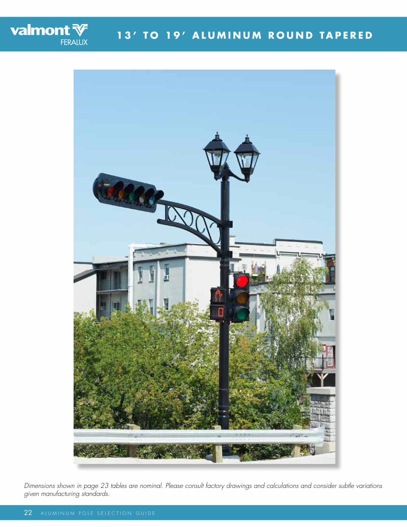
Dimensions shown in page 23 tables are nominal. Please consult factory drawings and calculations and consider subtle variations given manufacturing standards.

23
T R A F F i C T R u S S A R m P O L E S
CatalogueNumber
L -
Rea
ch
arm
Con
figur
atio
n
Reac
h (m
)
Wal
l Thk
. (m
m)
Arm
Rise
(m)
Tubi
ng O
D (m
m)
14”
24”
A-TTA-14 0.356 4.780 102A-TTA-18
A-TTA-2418” 0.457
0.6000
102102
4.784.78
CatalogueNumber
Hei
ght
Base Casting Anchor Bolt
Pole
Con
figur
atio
n
Wei
ght (
Kg)
sq (m
m)
BCD
Min
. (m
m)
aB
Diam
eter
(in)
Proj
ectio
n(s
him
lvl.)
(mm
)
Proj
ectio
n(N
ut lv
l.) (m
m)
aB
leng
th (i
n)
Shaft
Base
OD
(mm
)
Top
OD
(mm
)
BCD
(mm
)
BCD
Max
. (m
m)
13’
17’
19’
A-rT-TTA-13-0.188-x.x 137.8 305 279 36 70 120203 168 292 305A-rT-TTA-13-0.25-x.x
A-rT-TTA-15-0.188A-x.x
A-rT-TTA-15-0.25A-x.xA-rT-TTA-15-0.188B-x.xA-rT-TTA-15-0.25B-x.xA-rT-TTA-17-0.188A-x.x
15’
A-rT-TTA-17-0.25A-x.xA-rT-TTA-17-0.188B-x.xA-rT-TTA-17-0.25B-x.xA-rT-TTA-19-0.188A-x.x
A-rT-TTA-19-0.188B-x.xA-rT-TTA-19-0.25B-x.x
A-rT-TTA-19-0.25A-x.x
47.742.453.8
48.5
61.4
47
203203203
254
254
203
168168168
168
168
168
305305305
330
330
305
279279279
330
330
305
292292292
356
356
305
305305305
381
381
305
111
1
1.25
1
36 70 12036 70 120
36 70 120
36 76 12748 76 13336 70 120
59.9
53.7
68.3
51.6
230
254
254
203
168
168
168
168
305
330
330
305
305
330
330
305
305
356
356
305
305
381
381
305
1
1
1.25
1
36 70 120
36 76 12748 76 13336 70 120
66
58.9
75.3
203
254
254
168
168
168
305
330
330
305
330
330
305
356
356
305
381
381
1
1
1.25
36 70 120
36 76 12748 76 133
The poles are designed to work with the Traffic Truss Arms. For EPA rating and Base Reactions details please contact the factory. Alternate heights and loadings may be considered in the proper applications. Please contact the factory for poles not on the PSG list.
CatalogueNumber
L -
Rea
ch
arm
Con
figur
atio
n
l - R
each
(m)
Wal
l Thk
. (m
m)
Arm
H -
Rise
(m)
Tubi
ng O
D (m
m)
72”
120”
A-TTA-72 1.80 4.781.14 102A-TTA-96A-TTA-120
A-TTA-144
96” 2.438
3.658
1.143
1.143
102102
102
4.784.78
4.78144”
3.00 1.143

24 A L U M I n U M P o L E S E L E c T I o n G U I d E
8 ’ T O 3 5 ’ A L u m i N u m S Q u A R E S T R A i G H T
sURfaCE MOUNTED aCCEss COvER
BOlT CIRClE
TaMPER REsIsTaNT NUT COvER DIsKs
CasT alUMINUM aNCHOR BasE a356-T6 allOy
sqUaRE
square straight square straight Cruciform
cruciform Straight
Dimensions shown in page 25 tables are nominal. Please consult factory drawings and calculations and consider subtle variations given manufacturing standards.
Please contact the factory for suggested pole sizes required to achieve luminaire mounting heights.

25
4 - B O LT A N C H O R B A S E P O L E S
aluminum square straight Poles 8’ - 25’
0.59
q<=7
50Pa
0.52
q<=8
30Pa
CatalogueNumber max. EPA (m2)
Hei
ght
Base Casting Anchor Bolt
Pole
Con
figur
atio
n
Wei
ght (
Kg)
sq (m
m)
BCD
Min
. (m
m)
aB
Diam
eter
(in)
Proj
ectio
n(s
him
lvl.)
(mm
)
Proj
ectio
n(N
ut lv
l.) (m
m)
aB
leng
th (i
n)
q<=3
60Pa
q<=4
10Pa
q<=4
60Pa
q<=5
60Pa
q<=6
50Pa
Shaft
Base
sq.
(mm
)
Top
sq. (
mm
)
BCD
(mm
)
BCD
Max
. (m
m)
8’
18’
A-4cS-8-0.188-x.x 116 252 216 36 83 127 1.43 1.23 1.08 0.86 0.71102 102 229 241A-4cS-10-0.188-x.x
A-4cS-15-0.188-x.x
A-6cS-18-0.188-x.xA-4cS-20-0.188-x.x
12’
20’
192227
32
102102102
102
102102102
102
252252252
252
216216
216
216
229229
229
229
241241
241
241
111
1
36 83 12736 83 127
36 83 127
36 83 127
1.100.850.57
0.34
0.940.710.45
0.25
0.810.600.36
0.17
0.350.51
0.260.41
0.15
--------
0.08
--------
0.350.210.04
--------
0.620.450.24
0.07
A-4cS-12-0.188-x.x
35 252 216102 102 1229 241 -------- --------36 83 127 0.22 0.13 0.07 -------- --------
A-4cS-18-0.188-x.x50 324 305152 152 1318 330 0.21 0.13102 152 1.14 0.92 0.75 0.50 0.3436
25’A-6cS-20-0.188-x.x 55 324 305152 152 1318 330 0.05 --------36 102 152 0.90 0.70 0.54 0.32 0.17
A-6cS-25-0.188-x.x 67 324 305152 152 1318 330 -------- --------36 102 152 0.39 0.23 0.11 -------- --------
10’
15’
aluminum square straight Poles 8’ - 35’
Alternate heights and loadings may be considered in the proper applications. Please contact the factory for poles not on the PSG list.
0.35
q<=7
50Pa
0.30
q<=8
30Pa
CatalogueNumber max. EPA (m2)
Hei
ght
Base Casting Anchor Bolt
Pole
Con
figur
atio
n
Wei
ght (
Kg)
sq (m
m)
BCD
Min
. (m
m)
aB
Diam
eter
(in)
Proj
ectio
n(s
him
lvl.)
(mm
)
Proj
ectio
n(N
ut lv
l.) (m
m)
aB
leng
th (i
n)
q<=3
60Pa
q<=4
10Pa
q<=4
60Pa
q<=5
60Pa
q<=6
50Pa
Shaft
Base
sq.
(mm
)
Top
sq. (
mm
)
BCD
(mm
)
BCD
Max
. (m
m)
8’
15’
A-4SS-8-0.125-x.x 0.7511.8 252 216 24 83 127 0.93 0.79 0.69 0.53 0.44102 102 229 241A-4SS-10-0.125-x.x
A-4SS-14-0.125-x.x
A-4SS-16-0.125-x.xA-4SS-16-0.188-x.x
12’
16’
13.916
18.2
19.2
102102102
102
102102102
102
252252252
252
216216
216
216
229229
229
229
241241
241
241
0.750.750.75
0.75
24 83 12724 83 127
24 83 127
24 83 127
0.690.500.35
0.28
0.570.400.26
0.20
0.490.330.20
0.14
0.150.28
0.090.21
0.04
--------
--------
--------
0.170.06--------
--------
0.360.220.10
0.05
A-4SS-12-0.125-x.x
28.9 252 216102 102 0.75229 241 0.03 --------24 83 127 0.49 0.38 0.30 0.18 0.10
A-4SS-15-0.125-x.x20.3 252 216102 102 0.75229 241 -------- --------83 127 0.22 0.14 0.08 -------- --------24
18’A-4SS-18-0.188-x.x 32.1 252 216102 102 0.75229 241 -------- --------24 83 127 0.34 0.25 0.17 0.07 --------
A-4SS-18-0.188-x.x 40.4 294 273127 127 0.75283 292 0.05 --------24 83 127 0.69 0.54 0.42 0.25 0.14
10’
14’
-------- --------
20’
35’
A-5SS-20-0.188-x.x 0.7544.4 294 273 24 83 127 0.51 0.37 0.27 0.11 0.01127 127 283 292A-6SS-20-0.188-x.x
A-6SS-25-0.25-x.x
A-6SS-32-0.25-x.xA-6.75SS-35-0.25-x.x
30’
5570.886.7
117
152152152
171
152152152
171
324324324
384
305305
305
359
318318
318
372
330330
330
385
111
1
36 102 15236 102 152
36 102 152
36 108 158
0.901.390.80
0.59
0.701.130.59
0.36
0.540.930.42
0.19
0.450.17
0.290.05
0.03
--------
--------
--------
--------0.19--------
--------
0.320.640.18
--------
A-6SS-20-0.25-x.x
135 384 359171 171 1372 385 -------- --------36 108 158 0.11 -------- -------- -------- --------
A-6.75SS-30-0.25-x.x109 324 305152 152 1318 330 -------- --------102 152 0.16 -------- -------- -------- --------36
25’
32’
8 ’ T O 2 5 ’ A L u m i N u m C R u C i F O R m S T R A i G H T

26 A L U M I n U M P o L E S E L E c T I o n G U I d E
8 ’ T O 1 4 ’ A L u m i N u m R O u N D S T R A i G H T
Base Casting Detail
sqUaRE
BOlT CIRClE
anchor Base Detail
DIaMETER
CasT alUMINUM NUT COvER
Tenon Mounted fixture Detail side Mounted fixture Detail
REMOvaBlE CaP
POlE May BE DRIllED TO aCCEPT sIDE MOUNTED fIXTURE If REqUIRED. DRIllING DETaIl TO BE PROvIDED.
127
mm
TENON OD: sEE CHaRT

27
4 - B O LT A N C H O R B A S E P O L E S
aluminum Round straight Poles 8’ - 14’
0.32
q<=7
50Pa
0.27
q<=8
30Pa
CatalogueNumber max. EPA (m2)
Hei
ght
Base Casting Anchor Bolt
Pole
Con
figur
atio
n
Wei
ght (
Kg)
sq (m
m)
BCD
Min
. (m
m)
aB
Diam
eter
(in)
Proj
ectio
n(s
him
lvl.)
(mm
)
Proj
ectio
n(N
ut lv
l.) (m
m)
aB
leng
th (i
n)
q<=3
60Pa
q<=4
10Pa
q<=4
60Pa
q<=5
60Pa
q<=6
50Pa
Shaft
Base
OD
(mm
)
Top
OD
(mm
)
BCD
(mm
)
BCD
Max
. (m
m)
8’A-4rS-8-0.125-x.x 0.759.22 222 165 24 89 133 0.80 0.68 0.60 0.47 0.39102 102 187 210A-4.5rS-8-0.125-x.x
A-4rS-10-0.125-x.x
A-4.5rS-10-0.188-x.xA-5rS-10-0.125-x.x
12’
1013.810.9
11.9
114114102
114
114114102
114
222222222
222
178178
165
178
198198
187
198
219219
210
219
0.750.750.75
0.75
24 89 13324 89 133
24 89 133
24 89 133
1.021.550.60
0.78
0.881.340.51
0.66
0.771.180.43
0.57
0.800.50
0.670.42
0.26
0.35
0.20
0.28
0.260.590.17
0.23
0.610.950.33
0.44
A-4.5rS-8-0.188-x.x
13.3 235 191127 127 0.75216 241 0.37 0.3224 89 133 0.99 0.85 0.73 0.57 0.46
A-4.5rS-10-0.125-x.x16.6 222 178114 114 0.75198 219 0.49 0.4289 133 1.21 1.04 0.91 0.72 0.5924
A-4rS-12-0.125-x.x 12.6 222 165102 102 0.75187 210 0.11 0.0824 89 133 0.45 0.37 0.31 0.22 0.16
A-4.5rS-12-0.125-x.x 13.8 222 178114 114 0.75198 219 0.17 0.1324 89 133 0.59 0.49 0.42 0.30 0.23
10’
14’
A-4.5rS-12-0.188-x.x 19.5 222 178114 114 0.75198 219 0.35 0.2924 89 133 0.97 0.82 0.71 0.54 0.44A-5rS-12-0.125-x.x 15.4 235 191127 127 0.75216 241 0.24 0.2024 89 133 0.77 0.65 0.55 0.41 0.32A-5rS-12-0.156-x.x 18.5 235 191127 127 0.75216 241 0.36 0.3024 89 133 1.10 0.85 0.73 0.56 0.45A-5rS-12-0.188-x.x 21.7 235 191127 127 0.75216 241 0.47 0.4024 89 133 1.24 1.06 0.92 0.71 0.58A-4.5rS-14-0.125-x.x 15.7 222 178114 114 0.75198 219 0.08 0.0524 89 133 0.45 0.36 0.29 0.19 0.13A-4.5rS-14-0.188-x.x 22.3 222 178114 114 0.75198 219 0.23 0.1924 89 133 0.77 0.65 0.55 0.40 0.31A-5rS-14-0.125-x.x 17.4 235 191127 127 0.75216 241 0.13 0.0924 89 133 0.59 0.49 0.40 0.28 0.20A-5rS-14-0.156-x.x 21.1 235 191127 127 0.75216 241 0.23 0.1824 89 133 0.80 0.67 0.56 0.41 0.31A-5rS-14-0.188-x.x 24.8 235 191127 127 0.75216 241 0.33 0.2724 89 169 1.00 0.85 0.72 0.54 0.43
Alternate heights and loadings may be considered in the proper applications. Please contact the factory for poles not on the PSG list.
Dimensions shown in tables are nominal. Please consult factory drawings and calculations and consider subtle variations given manufacturing standards.Please contact the factory for suggested pole sizes required to achieve luminaire mounting heights.

28 A L U M I n U M P o L E S E L E c T I o n G U I d E
1 6 ’ T O 2 5 ’ A L u m i N u m R O u N D S T R A i G H T
Base Casting Detail
sqUaRE
BOlT CIRClE
anchor Base Detail
DIaMETER
CasT alUMINUM NUT COvER
Tenon Mounted fixture Detail side Mounted fixture Detail
REMOvaBlE CaP
POlE May BE DRIllED TO aCCEPT sIDE MOUNTED fIXTURE If REqUIRED. DRIllING DETaIl TO BE PROvIDED.
127
mm
TENON OD: sEE CHaRT

29
4 - B O LT A N C H O R B A S E P O L E S
aluminum Round straight Poles 16’ - 25’
Alternate heights and loadings may be considered in the proper applications. Please contact the factory for poles not on the PSG list.
---------
q<=7
50Pa
---------
q<=8
30Pa
CatalogueNumber max. EPA (m2)
Hei
ght
Base Casting Anchor Bolt
Pole
Con
figur
atio
n
Wei
ght (
Kg)
sq (m
m)
BCD
Min
. (m
m)
aB
Diam
eter
(in)
Proj
ectio
n(s
him
lvl.)
(mm
)
Proj
ectio
n(N
ut lv
l.) (m
m)
aB
leng
th (i
n)
q<=3
60Pa
q<=4
10Pa
q<=4
60Pa
q<=5
60Pa
q<=6
50Pa
Shaft
Base
OD
(mm
)
Top
OD
(mm
)
BCD
(mm
)
BCD
Max
. (m
m)
16’
A-4rS-16-0.125-x.x 116 222 165 36 83 127 0.23 0.17 0.12 0.05 ---------102 102 187 210A-4.5rS-16-0.125-x.x
A-5rS-16-0.125-x.x
A-5rS-16-0.188-x.xA-6rS-16-0.156-x.x
20’
182520
24
114114127
127
114114127
127
222222235
235
178178
191
191
198198
216
216
219219
241
241
111
1
36 83 12736 83 127
36 83 127
36 83 127
0.330.610.45
0.63
0.250.500.35
0.51
0.190.410.28
0.42
0.200.04
0.14---------
0.10
0.20
0.04
0.13
---------0.09---------
0.08
0.100.290.17
0.28
A-4.5rS-16-0.188-x.x
28 260 222152 152 1241 260 0.33 0.2936 89 133 0.99 0.82 0.69 0.50 0.40
A-5rS-16-0.156-x.x28 235 191127 127 1216 241 0.21 0.1683 127 0.81 0.67 0.56 0.40 0.3036
A-6rS-16-0.188-x.x 34 260 222152 152 1241 260 0.46 0.4036 89 133 1.26 1.06 0.90 0.67 0.55
A-4.5rS-18-0.188-x.x 28 222 178114 114 1198 219 0.05 0.0136 83 127 0.48 0.38 0.30 0.18 0.11
18’
25’
A-5rS-18-0.125-x.x 22 235 191127 114 1216 241 --------- ---------36 83 127 0.32 0.23 0.17 0.07 0.01A-5rS-18-0.156-x.x 26 235 191127 127 1216 241 0.03 ---------36 83 127 0.48 0.38 0.29 0.17 0.10A-5rS-18-0.188-x.x 31 235 191127 127 1216 241 0.11 0.0736 83 127 0.65 0.52 0.42 0.28 0.19A-6rS-18-0.188-x.x 37 260 222152 127 1241 260 0.33 0.2936 89 133 1.03 0.85 0.71 0.50 0.40A-4.5rS-20-0.188-x.x 31 222 178114 114 1198 219 --------- ---------36 83 127 0.36 0.27 0.20 0.09 0.03A-5rS-20-0.156-x.x 29 235 191127 127 1216 241 --------- ---------36 83 127 0.36 0.26 0.19 0.08 ---------A-5rS-20-0.188-x.x 34 235 191127 127 1216 241 0.02 ---------36 83 127 0.50 0.39 0.30 0.17 0.09A-6rS-20-0.156-x.x 35 260 222152 152 1241 260 0.11 0.0936 89 133 0.62 0.48 0.38 0.22 0.16A-6rS-20-0.188-x.x 41 260 222152 152 1241 260 0.22 0.1836 89 133 0.84 0.67 0.55 0.36 0.28A-6rS-25-0.188-x.x 50 260 222152 152 1241 260 --------- ---------36 89 133 0.45 0.31 0.21 0.05 0.01
Dimensions shown in tables are nominal. Please consult factory drawings and calculations and consider subtle variations given manufacturing standards.
Please contact the factory for suggested pole sizes required to achieve luminaire mounting heights.

30 A L U M I n U M P o L E S E L E c T I o n G U I d E
8 ’ T O 2 0 ’ A L u m i N u m R O u N D S T R A i G H T
Alternate heights and loadings may be considered in the proper applications. Please contact the factory for poles not on the PSG list.
aluminum Round straight Hinged Base Poles 8’ - 20’
0.32
q<=7
50Pa
0.27
q<=8
30Pa
CatalogueNumber max. EPA (m2)
Hei
ght
Base Casting Anchor Bolt
Pole
Con
figur
atio
n
Wei
ght (
Kg)
OD
(mm
)
BCD
Min
. (m
m)
aB
Diam
eter
(in)
Proj
ectio
n(s
him
lvl.)
(mm
)
Proj
ectio
n(N
ut lv
l.) (m
m)
aB
leng
th (i
n)
q<=3
60Pa
q<=4
10Pa
q<=4
60Pa
q<=5
60Pa
q<=6
50Pa
Shaft
Base
OD
(mm
)
Top
OD
(mm
)
BCD
(mm
)
BCD
Max
. (m
m)
8’ A-4rS-H-8-0.125-x.x 0.7512 321 216 24 89 133 0.80 0.68 0.60 0.47 0.39102 102 235 254A-4rS-H-10-0.125-x.x
A-4rS-H-12-0.125-x.x
A-5rS-H-12-0.156-x.xA-5rS-H-12-0.188-x.x
12’
13.615.715.3
17.8
102127102
127
102127102
127
321321321
321
216216
216
216
235235
235
235
254254
254
254
0.750.750.75
0.75
24 89 13324 89 133
24 89 133
24 89 133
0.600.990.45
0.77
0.510.850.37
0.65
0.430.730.31
0.55
0.460.26
0.370.20
0.16
0.32
0.11
0.24
0.170.320.08
0.20
0.330.570.22
0.41
A-5rS-H-10-0.125-x.x
24.1 321 216127 127 0.75235 254 0.47 0.4024 89 133 1.24 1.06 0.92 0.71 0.58
A-5rS-H-12-0.125-x.x20.9 321 216127 127 0.75235 254 0.36 0.3089 133 1.01 0.85 0.73 0.56 0.4524
A-4rS-H-14-0.125-x.x 17 321 216102 102 0.75235 254 0.04 0.0124 89 133 0.33 0.26 0.21 0.13 0.08
A-5rS-H-14-0.125-x.x 19.9 321 216127 127 0.75235 254 0.13 0.0924 89 133 0.59 0.49 0.40 0.28 0.20
10’
18’
A-5rS-H-14-0.156-x.x 23.5 321 216127 127 0.75235 254 0.23 0.1824 89 133 0.80 0.67 0.56 0.41 0.31A-5rS-H-14-0.188-x.x 27.2 321 216127 127 0.75235 254 0.33 0.2724 89 169 1.00 0.85 0.72 0.54 0.43A-5rS-H-16-0.125-x.x 22.0 321 216127 127 0.75235 254 0.04 ----------24 89 133 0.45 0.35 0.28 0.17 0.10A-5rS-H-16-0.156-x.x 26.1 321 216127 127 0.75235 254 0.13 0.0824 89 133 0.63 0.51 0.42 0.28 0.20A-5rS-H-16-0.188-x.x 30.4 321 216127 127 0.75235 254 0.21 0.1624 89 133 0.81 0.67 0.56 0.40 0.30A-6rS-H-16-0.156-x.x 30.2 321 216152 152 0.75235 254 0.33 0.2924 89 133 0.99 0.82 0.69 0.50 0.40A-6rS-H-16-0.188-x.x 35.4 321 216152 152 0.75235 254 0.46 0.4036 89 133 1.26 1.06 0.90 0.67 0.55A-5rS-H-18-0.156-x.x 28.7 321 216127 127 0.75235 254 0.03 ----------36 89 133 0.48 0.38 0.29 0.17 0.10A-5rS-H-18-0.188-x.x 33.5 321 216127 127 0.75235 254 0.11 0.0736 89 133 0.65 0.52 0.42 0.28 0.19A-6rS-H-18-0.188-x.x 39.1 321 216152 152 0.75235 254 0.33 0.2936 89 133 1.03 0.85 0.71 0.50 0.40A-5rS-H-20-0.156-x.x 31.3 321 216127 127 0.75235 254 ---------- ----------36 89 133 0.36 0.26 0.19 0.08 ----------A-5rS-H-20-0.188-x.x 36.7 321 216127 127 0.75235 254 0.02 ----------36 89 133 0.50 0.39 0.30 0.17 0.09A-6rS-H-20-0.156-x.x 36.5 321 216152 152 0.75235 254 0.11 0.0936 89 133 0.62 0.48 0.38 0.22 0.16A-6rS-H-20-0.188-x.x 42.9 321 216152 152 0.75235 254 0.22 0.1836 89 133 0.84 0.67 0.55 0.36 0.28
14’
16’
20’
TWO PIECE CasT alUMINUM COvER
3/4” sOlID alUMINUM PIvOT ROD
TaPPED 3/8”-16 fOR GROUND CONNECTOR
1/4”-20 X 1/2” lONG sTaINlEss sTEEl allEN HEaD COUNTERsUNK
sCREWs
1/2” I.D. sPlIT lOCK WasHER
1/2” I.D. flaT WasHER
1/2”-13 sTaINlEss sTEEl BOlT

31
A N D R O u N D TA P E R E D H i N G E D B A S E P O L E S
aluminum Round Tapered Hinged Base Poles 8’ - 20’
Alternate heights and loadings may be considered in the proper applications. Please contact the factory for poles not on the PSG list.
0.34
q<=7
50Pa
0.04
q<=8
30Pa
CatalogueNumber max. EPA (m2)
Hei
ght
Base Casting Anchor Bolt
Pole
Con
figur
atio
n
Wei
ght (
Kg)
Dia
. (m
m)
BCD
Min
. (m
m)
aB
Diam
eter
(in)
Proj
ectio
n(s
him
lvl.)
(mm
)
Proj
ectio
n(N
ut lv
l.) (m
m)
aB
leng
th (i
n)
q<=3
60Pa
q<=4
10Pa
q<=4
60Pa
q<=5
60Pa
q<=6
50Pa
Shaft
Base
OD
(mm
)
Top
OD
(mm
)
BCD
(mm
)
BCD
Max
. (m
m)
8’ A-rT-H-8-0.125-x.x 0.7511 321 216 36 89 133 0.82 0.71 0.62 0.49 0.41102 76 235 254A-rT-H-10-0.125A-x.x
A-rT-H-12-0.125A-x.x
A-rT-H-12-0.156-x.xA-rT-H-12-0.188-x.x
12’
131414
15
102127102
127
767676
76
321321321
321
216216
216
216
235235
235
235
254254
254
254
0.750.750.75
0.75
36 89 13336 89 133
36 89 133
36 89 133
0.631.050.49
0.84
0.540.900.41
0.71
0.460.790.34
0.62
0.520.29
0.430.23
0.20
0.38
0.15
0.31
0.040.040.04
0.04
0.360.620.25
0.48
A-rT-H-10-0.125B-x.x
20 321 216127 76 0.75235 254 0.54 0.0436 89 133 1.31 1.13 0.99 0.78 0.65
A-rT-H-12-0.125B-x.x18 321 216127 76 0.75235 254 0.42 0.0489 133 1.07 0.92 0.80 0.63 0.5136
A-rT-H-14-0.125A-x.x 15 321 216102 76 0.75235 254 0.08 0.0436 89 133 0.37 0.30 0.25 0.17 0.12
A-rT-H-14-0.125B-x.x 17 321 216127 76 0.75235 254 0.21 0.0436 89 133 0.67 0.57 0.48 0.36 0.28
10’
18’
A-rT-H-14-0.156-x.x 20 321 216127 76 0.75235 254 0.31 0.0436 89 133 0.88 0.74 0.64 0.49 0.39A-rT-H-14-0.188-x.x 23 321 216127 76 0.75235 254 0.41 0.0436 89 133 1.09 0.93 0.80 0.62 0.51A-rT-H-16-0.125B-x.x 19 321 216127 76 0.75235 254 0.13 0.0436 89 133 0.54 0.44 0.37 0.26 0.19A-rT-H-16-0.156A-x.x 22 321 216127 76 0.75235 254 0.22 0.0436 89 133 0.72 0.60 0.51 0.37 0.29A-rT-H-16-0.188A-x.x 25 321 216127 76 0.75235 254 0.31 0.0436 89 133 0.90 0.76 0.65 0.49 0.39A-rT-H-16-0.156B-x.x 26 321 216152 102 0.75235 254 0.36 0.0436 89 133 1.08 0.91 0.78 0.58 0.46A-rT-H-16-0.188B-x.x 30 321 216152 102 0.75235 254 0.49 0.0436 89 133 1.35 1.15 0.99 0.76 0.61A-rT-H-18-0.125-x.x 20 321 216127 76 0.75235 254 0.02 0.0436 89 133 0.36 0.28 0.22 0.13 0.07A-rT-H-18-0.156A-x.x 24 321 216127 76 0.75235 254 0.09 0.0436 89 133 0.52 0.42 0.34 0.22 0.15A-rT-H-18-0.188A-x.x 28 321 216127 76 0.75235 254 0.21 0.0436 89 133 0.75 0.63 0.53 0.38 0.29A-rT-H-18-0.156B-x.x 29 321 216152 102 0.75235 254 0.25 0.0436 89 133 0.90 0.74 0.62 0.45 0.34A-rT-H-18-0.188B-x.x 34 321 216152 102 0.75235 254 0.36 0.0436 89 133 1.14 0.96 0.81 0.61 0.47A-rT-H-20-0.125-x.x 22 321 216127 76 0.75235 254 ---------- ----------36 89 133 0.32 0.25 0.19 0.10 0.04A-rT-H-20-0.156A-x.x 26 321 216127 76 0.75235 254 0.06 0.0336 89 133 0.47 0.38 0.30 0.19 0.12
14’
16’
20’ A-rT-H-20-0.188A-x.x 30 321 216127 76 0.75235 254 0.13 0.0936 89 133 0.62 0.51 0.42 0.29 0.20
A-rT-H-20-0.156B-x.x 31 321 216152 102 0.75235 254 0.15 0.1036 89 133 0.74 0.60 0.49 0.33 0.23A-rT-H-20-0.188B-x.x 37 321 216152 102 0.75235 254 0.25 0.1936 89 133 0.95 0.79 0.66 0.47 0.35
Dimensions shown in tables are nominal. Please consult factory drawings and calculations and consider subtle variations given manufacturing standards.
Please contact the factory for suggested pole sizes required to achieve luminaire mounting heights.

32 A L U M I n U M P o L E S E L E c T I o n G U I d E
F L U T I n G o P T I o n S
*contact factory for special manufacturing capabilities.
4W Flute
4-Sharp Flute
12-Flat Flute
8-Sharp Flute
16-Sharp Flute
16-Flat Flute
8-Flat Flute
STArT And SToP FLUTES
STArT And SToP FLUTES
8 ’ T O 3 2 ’ A L u m i N u m F L u T E D

33
aluminum Round Tapered fluted Poles 8’ - 32’
Alternate heights and loadings may be considered in the proper applications. Please contact the factory for poles not on the PSG list.
0.53
q<=7
50Pa
0.46
q<=8
30Pa
CatalogueNumber max. EPA (m2)
Hei
ght
Base Casting Anchor Bolt
Pole
Con
figur
atio
n
Wei
ght (
Kg)
sq (m
m)
BCD
Min
. (m
m)
aB
Diam
eter
(in)
Proj
ectio
n(s
him
lvl.)
(mm
)
Proj
ectio
n(N
ut lv
l.) (m
m)
aB
leng
th (i
n)
q<=3
60Pa
q<=4
10Pa
q<=4
60Pa
q<=5
60Pa
q<=6
50Pa
Shaft
Base
OD
(mm
)
Top
OD
(mm
)
BCD
(mm
)
BCD
Max
. (m
m)
8’A-rT-F-8-0.125-x.x 0.7510 244 219 24 83 127 1.28 1.10 0.97 0.76 0.64127 99 219 219A-rT-F-8-0.156-x.x
A-rT-F-10-0.156-x.x
A-rT-F-14-0.156-x.xA-rT-F-16-0.156A-x.x
12’
121214
20
127127127
152
999191
110
244244244
262
219219
219
241
219219
219
241
219219
219
241
0.750.750.75
0.75
24 83 12724 83 127
24 83 127
24 89 133
1.610.991.27
1.52
1.400.841.09
1.30
1.230.730.95
1.13
0.460.82
0.370.69
0.61
0.71
0.50
0.58
0.610.310.43
0.49
0.980.560.74
0.87
A-rT-F-10-0.125-x.x
24 262 241152 96 0.75241 241 0.29 0.2324 89 133 1.03 0.85 0.72 0.52 0.40
A-rT-F-12-0.156-x.x22 262 241152 103 0.75241 241 0.42 0.3589 133 1.25 1.05 0.90 0.68 0.5424
A-rT-F-16-0.156B-x.x 29 286 267178 121 1267 267 0.46 0.3736 105 155 1.46 1.23 1.04 0.78 0.60
A-rT-F-18-0.156-x.x 31 286 267178 114 1267 267 0.32 0.2436 105 155 1.22 1.01 0.84 0.60 0.45
10’
18’
A-rT-F-20-0.156-x.x 33 286 267178 107 1267 267 0.20 0.1336 105 155 1.02 0.83 0.68 0.46 0.32A-rT-F-20-0.188-x.x 48 306 292203 132 1292 292 0.52 0.4136 105 155 1.80 1.50 1.27 0.92 0.70A-rT-F-22-0.156-x.x 36 286 267178 100 1267 267 0.10 0.0336 105 155 0.85 0.67 0.54 0.33 0.21A-rT-F-22-0.188-x.x 51 306 292203 125 1292 292 0.37 0.2736 105 155 1.54 1.27 1.05 0.74 0.54A-rT-F-24-0.188-x.x 54 306 292203 118 1292 292 0.24 0.1536 105 155 1.32 1.07 0.87 0.58 0.40A-rT-F-26-0.188-x.x 57 306 292203 111 1292 292 0.13 0.0436 105 155 1.13 0.90 0.71 0.44 0.27A-rT-F-28-0.188-x.x 59 306 292203 104 1292 292 0.03 --------36 105 155 0.96 0.75 0.58 0.32 0.16A-rT-F-30-0.188-x.x 84 335 362254 147 1362 362 0.08 --------36 121 171 1.46 1.14 0.88 0.51 0.28A-rT-F-32-0.188-x.x 88 335 362254 140 1362 362 -------- --------36 121 171 1.25 0.95 0.71 0.36 0.14
14’
16’
20’
22’
24’26’28’30’32’
clean, crisp and uniform flute transition.
TA P E R E D R O u N D P O L E S
Dimensions shown in tables are nominal. Please consult factory drawings and calculations and consider subtle variations given manufacturing standards.
Please contact the factory for suggested pole sizes required to achieve luminaire mounting heights.

34 A L U M I n U M P o L E S E L E c T I o n G U I d E
A L u m i N u m R O u N D T A P E R E D i D Y L i N E
Base Casting Detail
sqUaRE
BOlT CIRClE
luminaire arm

35
C u R V E A N D S i G m A P O L E S
Alternate heights and loadings may be considered in the proper applications. Please contact the factory for poles not on the PSG list.
aluminum Round Tapered Idyline Curve Poles 15’ - 28’
0.37
q<=7
50Pa
0.31
q<=8
30Pa
CatalogueNumber max. EPA (m2)
Hei
ght
Base Casting Anchor Bolt
Pole
Con
figur
atio
n
Wei
ght (
Kg)
sq (m
m)
BCD
Min
. (m
m)
aB
Diam
eter
(in)
Proj
ectio
n(s
him
lvl.)
(mm
)
Proj
ectio
n(N
ut lv
l.) (m
m)
aB
leng
th (i
n)
q<=3
60Pa
q<=4
10Pa
q<=4
60Pa
q<=5
60Pa
q<=6
50Pa
Shaft
Base
OD
(mm
)
Top
OD
(mm
)
BCD
(mm
)
BCD
Max
. (m
m)
15’ A-rT-Ic-15-0.188-x.x 0.7521 216 216 24 89 133 0.97 0.85 0.73 0.56 0.46140 60 216 216A-rT-Ic-19-0.188-x.x
A-rT-Ic-16.5-0.188-x.x
A-rT-Ic-25-0.188-x.xA-rT-Ic-28-0.188-x.x
27’-6”264523
39
140178140
178
606060
60
216267216
267
216267
216
267
216267
216
267
216267
216
267
0.751
0.75
1
36 108 15824 89 133
24 89 133
36 108 158
0.630.52
0.79
0.81
0.570.50
0.70
0.74
0.480.40
0.61
0.62
0.160.26
0.090.19
0.37
0.33
0.29
0.25
0.150.05
0.24
0.19
0.350.26
0.46
0.44
A-rT-Ic-27.5-0.188-x.x
46 267 267178 60 1267 267 0.07 0.0336 108 158 0.50 0.48 0.38 0.24 0.15
A-rT-Ic-23.5-0.188-x.x42 267 267178 60 1267 267 0.18 0.13108 158 0.70 0.64 0.53 0.37 0.2736
A-rT-Ic-17-0.188-x.x 23 216 216140 60 0.75216 216 0.27 0.2224 89 133 0.74 0.66 0.57 0.43 0.34
A-rT-Ic-19-0.188A-x.x 26 216 216140 60 0.75216 216 0.19 0.1524 89 133 0.60 0.54 0.46 0.34 0.26
19’
17’
A-rT-Ic-26-0.188-x.x 43 267 267178 60 1267 267 0.15 0.1036 108 158 0.65 0.61 0.49 0.33 0.23
25’28’
19’26’
16’-6”
23’-6”
Alternate heights and loadings may be considered in the proper applications. Please contact the factory for poles not on the PSG list.
aluminum Round Tapered Idyline sigma Poles 16’ - 28.5’
0.32q<
=750
Pa0.27
q<=8
30Pa
CatalogueNumber max. EPA (m2)
Hei
ght
Base Casting Anchor Bolt
Pole
Con
figur
atio
n
Wei
ght (
Kg)
sq (m
m)
BCD
Min
. (m
m)
aB
Diam
eter
(in)
Proj
ectio
n(s
him
lvl.)
(mm
)
Proj
ectio
n(N
ut lv
l.) (m
m)
aB
leng
th (i
n)
q<=3
60Pa
q<=4
10Pa
q<=4
60Pa
q<=5
60Pa
q<=6
50Pa
BP T
hk. (
mm
)
BCD
(mm
)
BCD
Max
. (m
m)
16’ A-rT-IS-16-0.188A-x.x 0.7522.1 216 216 24 89 133 0.87 0.77 0.66 0.50 0.40216 216 19A-rT-IS-20-0.188-x.x
A-rT-IS-28.5-0.188A-x.x
A-rT-IS-25.5-0.188B-x.xA-rT-IS-28.5-0.188B-x.x
25’-6”27.142.346.7
22.1
216267267
216
216267267
216
216267267
216
216267
267
216
1925
25
19
0.7511
0.75
36 108 15824 89 133
36 108 158
24 89 133
0.580.70
0.50
0.88
0.530.64
0.48
0.77
0.440.53
0.38
0.66
0.250.23
0.170.16
0.13
0.40
0.06
0.32
0.120.12
0.01
0.27
0.310.36
0.22
0.51
A-rT-IS-25.5-0.188A-x.x
46.7 267 267267 267 125 0.06 0.0136 108 158 0.49 0.47 0.37 0.22 0.13
A-rT-IS-16-0.188B-x.x42.3 267 267267 267 125 0.16 0.12108 158 0.66 0.62 0.51 0.35 0.2536
A-rT-IS-16-0.188c-x.x 22.1 216 216216 216 0.7519 0.31 0.2624 89 133 0.81 0.72 0.63 0.48 0.39
A-rT-IS-25.5-0.188c-x.x 42.3 267 267267 267 125 0.16 0.1136 108 158 0.66 0.61 0.50 0.34 0.24
20’
16’
A-rT-IS-28.5-0.188c-x.x 46.7 267 267267 267 125 0.06 0.0136 108 158 0.46 0.44 0.35 0.21 0.13
25’-6”28’-6”
25’-6”28’-6”
28’-6”
16’
Dimensions shown in tables are nominal. Please consult factory drawings and calculations and consider subtle variations given manufacturing standards.
Please contact the factory for suggested pole sizes required to achieve luminaire mounting heights.

36 A L U M I n U M P o L E S E L E c T I o n G U I d E
S P E C i F i C A T i O N S
Valmont Feralux and West coast Engineering employs state-of-the-art Powder coating Technology to provide a beautiful, durable, and long lasting finish on our poles and accessories.
I n T r o d U c T I o n
Valmont Feralux and West coast Engineering warranties the integrity of the structure and product finish for a period of one year from the date of shipment. The warranty is limited to repairing or replacing product that exhibits defects in material or workmanship. Valmont Feralux and West coast Engineering will not accept claims for incidental costs due to delays or extra labor charges incurred. As the fabricator, Valmont Feralux and West coast Engineering assumes full responsibility for the products and finishes we provide.
W A r r A n T Y
The shaft shall be extruded and/or spun tapered from seamless 6063 alloy aluminum and shall be heat treated to produce a T6 temper. After manufacturing, the shafts are circumferentially or longitudinally polished, resulting in a high quality satin brushed finish.
P o L E S H A F T S
The anchor base is cast from A356 alloy aluminum and is circumferentially welded to the shaft. The completed assembly shall be heat treated to T6 temper after structural welding is completed. A356 alloy nut covers are provided unless otherwise specified.
B A S E c A S T I n G S
Each pole shall include (4) carbon steel, hot dip galvanized anchor bolts, each with (2) nuts and (2) flat washers sized to match the anchor bolts. Materials to be A36 modified to 55,000 psi minimum yield strength.
A n c H o r B o L T S

37
C O A T i N G S
Prior to finishing, poles are polished to create a profile for paint adhesion. Fluted or irregularly shaped items are chemically cleaned to accept the finish. The powder is electrostatically applied and cured in a convection oven according to the manufacturer’s recommendations. Prior to shipment, parts are wrapped to prevent damage during transit.
P o W d E r
S T A n d A r d c o L o r S
Anodizing is an electrolytic process in an acid bath used to increase the thickness of the layer of natural oxide on the surface of the metal. duranodic is an anodized finish that has become the name of integral color or tint. Integral color simply means that the anodizing and coloring take place in a single step.
A n o d I Z I n G
S T A n d A r d c o L o r S
clear naturalLight BronzeMedium Bronzedark BronzeBlack
•••••
WhiteSandstoneBurgundyHunter Greennatural Aluminumcharcoal GrayMedium BronzeSanded Brown
••••••••
new dark Bronzedark BronzeSanded BlackBlackSteel Bluedark GreenBright red
•••••••
* contact the factory if your project requirements call for wet paint finishes.

38 A L U M I n U M P o L E S E L E c T I o n G U I d E
D E S i G N S T A N D A R D S
Pole Type Design series
Pole Numbering system
W XXX YY ZZ X.X
stra
ight
or T
aper
ed s
haft
O. D
.
Pole
Typ
e
Pole
Hei
ght
shaf
t Thi
ckne
ss -
sqT
and
ROT
Teno
n si
ze o
r “0”
for r
emov
able
to
p ca
p co
nfigu
ratio
n
Pole Typeround TaperedrTround Tapered EmbeddedSingle davitdouble davitSingle Member ArmPost-Top Traffic
Traffic Truss Arm
Description
rT-ESddd
SMATPTTTA
Square StraightSSround Straightround Straight Hingedround Tapered Hingedround Tapered Flutedround Tapered Idyline curveround Tapered Idyline Sigma
rSrS-HrT-HrT-FrT-IcrT-IS
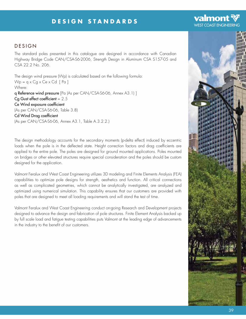
39
D E S i G N S T A N D A R D S
The standard poles presented in this catalogue are designed in accordance with canadian Highway Bridge code cAn/cSA-S6-2006, Strength design in Aluminum cSA S157-05 and cSA 22.2 no. 206.
The design wind pressure (Wp) is calculated based on the following formula:Wp = q x cg x ce x cd [ Pa ]Where:q Reference wind pressure [Pa (As per cAn/cSA-S6-06, Annex A3.1) ]Cg Gust effect coefficient = 2.5Ce Wind exposure coefficient(As per cAn/cSA-S6-06, Table 3.8)Cd Wind Drag coefficient(As per cAn/cSA-S6-06, Annex A3.1, Table A.3.2.2.)
D E s I G N
The design methodology accounts for the secondary moments (p-delta effect) induced by eccentric loads when the pole is in the deflected state. Height correction factors and drag coefficients are applied to the entire pole. The poles are designed for ground mounted applications. Poles mounted on bridges or other elevated structures require special consideration and the poles should be custom designed for the application.
Valmont Feralux and West coast Engineering utilizes 3d modeling and Finite Elements Analysis (FEA) capabilities to optimize pole designs for strength, aesthetics and function. All critical connections as well as complicated geometries, which cannot be analytically investigated, are analyzed and optimized using numerical simulation. This capability ensures that our customers are provided with poles that are designed to meet all loading requirements and will stand the test of time.
Valmont Feralux and West coast Engineering conduct on-going research and development projects designed to advance the design and fabrication of pole structures. Finite Element Analysis backed up by full scale load and fatigue testing capabilities puts Valmont at the leading edge of advancements in the industry to the benefit of our customers.

40 A L U M I n U M P o L E S E L E c T I o n G U I d E
D E S i G N S T A N D A R D S
P O l E s E l E C T I O N a N D E Pa R aT I N G
1.
2.
From cAn/cSA-S6-2006, table A3.1.1, select the 25 year return value for wind pressure - q, for the project location.Select the Max EPA from the column in the table corresponding to the wind pressure - q, for the project locaation.
1.
2.
From cAn/cSA-S6-2006, table A3.1.1 -q (25 years return period) = 430 Pa
In the Aluminum Square Straight Poles table, select the
Max. EPA = 00.54 sq. m from the q,=460 Pacolumn for catalogue number A-655-20-0.188
Example:6” Square Straight 20’ pole installed in the Vancouver area.
To convert m2 to ft2, multiply the m2 value by 10.760.54m2 x 10.76 = 5.81 ft2
To convert ft2 to m2, divide the ft2 value by 10.765.81 ft2 / 10.76 = 0.54m2
EPA Conversion Formula1m2 = 10.76 ft2
Wind Pressure(Pa)
Gusted Wind Pressure(Pa)
Equivalent max. Wind Gust(km/h) / (mph)
460560650750830
41011501400162518752075
1025156/97
172/107185/115199/124209/130
147/91360 900 138/86

41
W i N D P R E S S u R E F O R C E S A C R O S S C A N A D A
Hou
rly m
ean
win
d pr
essu
re,
Pa, f
or re
turn
per
iods
of
10 yr Zv v Za alocation 25 yr 50 yr 100 yrve
loci
ty re
late
d se
ismic
zon
e,
Zona
l vel
ocity
ratio
,
acc
eler
atio
n re
late
d se
ismic
zon
e,
Zona
l acc
eler
atio
n ra
tio,
Abbotsfordchilliwackdawson creekKelownaLangleynanaimonew Westminsternorth VancouverPort AlberniPrince GeorgePrince rupertVancouverVictoriaalbertacalgarydrumhellerEdmontonFort McMurrayGrand PrairieJasperLethbridgeMedicine Hatsaskatchewannorth BattlefordPrince AlbertreginaSaskatoonSwift currentManitobaBrandonchurchillFlin FlonPortage la PrairieSt. BonifaceSt. VitalThompsonWinnipegOntarioAjaxBarrieBellevilleBowmanvilleBramptonBrockvilleBurlingtoncambridgedurhamFort ErieGuelphHamiltonKingstonKitchener
415475310340455470360360470280420360475
395315315270370365640395
450265340360455
375480330360350350370350
430210320460315315360265310365250365350275
530605365410560560420430560335485430560
455380390310430415745470
590325385425545
435570390415405405440405
510280380535380380415310380415295415415330
4411444452545
1----------
1----------
11
--------------------
--------------------------------------------------
--------------------------------------------------------------------------------
1111
----------1
------------------------------------------------------------
1----------
0.200.200.050.050.200.200.200.200.300.100.300.200.30
0.05----------0.05----------0.050.05--------------------
--------------------------------------------------
--------------------------------------------------------------------------------
0.050.050.050.050.050.050.050.050.050.050.050.050.050.05
British Columbia620715400470640635470480630370535480630
495430450350475455825535
705380420480620
490645440465450450490450
570330430590430430460350435460325460465370
710830440530730710520530700410590530690
540490510380520500910600
830440460540690
540720490510500500540490
640390480660490490510390500500360500520420
44
----------1
----------4
--------------------
5----------
346
--------------------------------------------------------------------------------
--------------------------------------------------
--------------------------------------------------------------------------------
111
----------1311121121
0.200.20----------0.05----------0.20--------------------0.30----------0.150.200.40
--------------------------------------------------0.05--------------------
--------------------------------------------------
--------------------------------------------------------------------------------
0.050.050.05----------0.050.150.050.050.050.100.050.050.100.05
Hou
rly m
ean
win
d pr
essu
re,
Pa, f
or re
turn
per
iods
of
10 yr Zv v Za alocation 25 yr 50 yr 100 yr
velo
city
rela
ted
seism
ic z
one,
Zona
l vel
ocity
ratio
,
acc
eler
atio
n re
late
d se
ismic
zon
e,
Zona
l acc
eler
atio
n ra
tio,
LondonMississauganewmarketnorth BayoakvilleoshawaottawaPeterboroughSarniaSault Ste. MarieSt. catherinesSudburyThunder BayTorontoWaterlooquebecdorvalGranbyHullLachineLavalMontrealnorandaQuebecSt-LaurentNew BrunswickEdmundstonFrederictonMonctonSaint JohnWoodstockNova scotiaAmherstdartmouthHalifaxPort HawkesburySydneyYarmouthPrince Edward IslandcharlottetownNewfoundland & labradorcape raceGanderSt. John’syukon TerritorydawsonWhitehorseNorthwest TerritoriesFort Good HopeInuvikYellowknifeNunavutIqaluit
365370260260375430295290350320365290300390275
315265295315315315260385315
300295460385275
410400400590465410
460
785460605
230280
480390345
565
455435325300435510360360415365415390355460330
365310360365365365310460365
380360560460330
510505505675535495
530
935535710
275330
565525415
670
--------------------
11
----------121
------------------------------
1------------------------------
222222132
31111
111121
1
111
44
121
----------
----------0.050.050.050.050.050.100.05--------------------0.050.05----------0.050.05
0.100.100.100.100.100.100.050.150.10
0.150.050.050.050.05
0.050.050.050.050.100.05
0.05
0.050.050.05
0.200.20
0.050.100.05
0.05
Ontario continued535495385340490575410415465400460465390520370
400350410400400400350520400
440410640520370
585590590740595560
590
1050595800
310370
635640470
750
610550440370540640460470520430500550430580420
440390460440440440390580440
510460720590420
660670670800650630
660
1170660890
340420
700760530
840
---------1121141
--------------------
11
----------11
434
----------44244
32222
111121
1
111
22
11
----------
1
---------0.050.050.100.050.050.200.05--------------------0.050.05----------0.050.05
0.200.150.20----------0.200.200.100.200.20
0.150.100.100.100.10
0.050.050.050.050.100.05
0.05
0.050.050.05
0.100.10
0.050.05----------
0.05

42 A L U M I n U M P o L E S E L E c T I o n G U I d E
N O T E S

43

BRO
1047
04/
11
VAllEy, nEBRASkA SAnTA FE SPRInGS, CAlIFORnIA AURORA, COlORADO ATlAnTA, GEORGIA ElkHART, InDIAnA
PlyMOUTH, InDIAnA FARMInGTOn, MInnESOTA HAUPPAUGE, nEW yORk SAlEM, OREGOn BREnHAM, TExAS
FERnDAlE, WASHInGTOn DElTA, BRITISH COlUMBIA WInnIPEG, MAnITOBA BARRIE, OnTARIO ST. JUlIE, QUEBEC
UnITED kInGDOM FRAnCE GERMAny FInlAnD ITAly TURkEy MOROCCO
nETHERlAnDS POlAnD ESTOnIA CHInA
SErVInG THE WorLd SIncE 1946
2250, BombardierSte-Julie, QC J3E 2l6
CAnADAPhone: 450.649.4114
Fax: 450.649.4940E-mail: [email protected]
Web: feralux.com
6823 northgate WayFerndale, WA 98248
USAPhone: 360.366.3400
Fax: 360.366.3401E-mail: [email protected]
Web: valmontwce.com
1450 Saskatchewan Ave.Winnipeg, MB R3E 0l3
CAnADAPhone: 204.987.3110
Fax: 204.775.9066E-mail: [email protected]
Web: valmontwce.com
100 Ellis Drive,Barrie, On l4n 9B2
CAnADAPhone: 800.645.1664
Fax: 800.367.1449E-mail: [email protected]
Web: valmontwce.com
7984 River Road,Delta, BC V4G 1E3
CAnADAPhone: 604.946.1256
Fax: 604.946.1203E-mail: [email protected]
Web: valmontwce.com

Alum
inum Po
le S
ele
ction G
uide