Embed Size (px)
Citation preview
CAT.8100S
10±0.1
2-φ2.0
(PC board hole dimensions) (Terminal dimensions)
4.0
±0.5
2.5
1.5+0.2-0.1
0.8+0.2-0.1
Polarity bar
10L±2
φD +1
MAX
.
4.0±0.5Pressure relief vent
0.8+0.2
-0.1
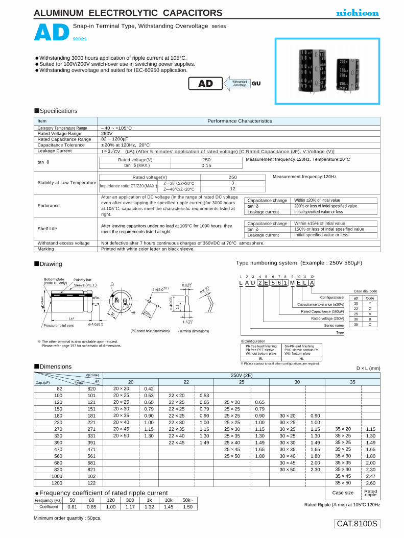
The other terminal is also available upon request.Please refer page 197 for schematic of dimensions.
±0.1Sleeve (P.E.T.)
Bottom plate(code HL only) L
1
A2
D3
24
E5
56
67
18
M9
E10
L11
A12
Configuration
Case dia. code
Capacitance tolerance (±20%)
Rated Capacitance (560µF)
Rated voltage (250V)
Series name
Type
φD
22
25
30
35
Code
Z
20 Y
A
B
C
Pb free lead finishingPb free PET sleeveWithout bottom plate
Sn-Pb lead finishingPVC sleeve contain PbWith bottom plate
EL HL
Configuration
Please contact to us if other configurations are required.
ALUMINUM ELECTROLYTIC CAPACITORS
AD series
Withstanding 3000 hours application of ripple current at 105°C.Suited for 100V/200V switch-over use in switching power supplies.Withstanding overvoltage and suited for IEC-60950 application.
a
Drawing Type numbering system (Example : 250V 560µF)
Snap-in Terminal Type, Withstanding Overvoltage series
DimensionsV(Code)
φD
250V (2E) 20 22 25 30 35
008201000120015001800220027003300390047005600680082010001200
820101121151181221271331391471561681821102122
20 × 2020 × 2520 × 2520 × 3020 × 3520 × 4020 × 4520 × 50
0.420.530.650.790.901.001.151.30
22 × 2022 × 2522 × 2522 × 2522 × 3022 × 3522 × 4022 × 45
0.530.650.790.901.001.151.301.49
25 × 2025 × 2525 × 2525 × 2525 × 3025 × 3525 × 4025 × 4525 × 50
0.650.790.901.001.151.301.491.651.80
30 × 2030 × 2530 × 2530 × 2530 × 3030 × 3530 × 4030 × 4530 × 50
0.901.001.151.301.491.651.802.002.30
35 × 2035 × 2535 × 2535 × 2535 × 3035 × 3535 × 4035 × 4535 × 50
1.151.301.491.651.802.002.302.472.60
Case size
Rated Ripple (A rms) at 105°C 120Hz
D × L (mm)
Cap.(µF) Code
Frequency (Hz)Coefficient
50 60 120 300 1k 10k 50k~0.81 0.85 1.00 1.17 1.32 1.45 1.50
Ratedripple
Category Temperature RangeRated Voltage RangeRated Capacitance RangeCapacitance ToleranceLeakage Current
tan δ
Stability at Low Temperature
Endurance
Shelf Life
Withstand excess voltageMarking
Not defective after 7 hours continuous charges of 360VDC at 70°C atmosphere.Printed with white color letter on black sleeve.
Performance CharacteristicsItem
– 40 ~ +105°C250V82 ~ 1200µF±20% at 120Hz, 20°C
Measurement frequency:120Hz, Temperature:20°C
Measurement frequency:120Hz
After leaving capacitors under no load at 105°C for 1000 hours, theymeet the requirements listed at right.
Within ±20% of intial value200% or less of intial spesified valueInitial specified value or less
Capacitance changetan δLeakage current
I (µA) (After 5 minutes' application of rated voltage) [C:Rated Capacitance (µF), V:Voltage (V)]
After an application of DC voltage (in the range of rated DC voltageeven after over-lapping the specified ripple current)for 3000 hoursat 105°C, capacitors meet the characteristic requirements listed atright.
Z—25°C/Z+20°CZ—40°C/Z+20°C
Specifications
Within ±15% of intial value150% or less of intial spesified valueInitial specified value or less
Capacitance changetan δLeakage current
Rated voltage(V)tan δ (MAX.)
2500.15
Rated voltage(V)
Impedance ratio ZT/Z20 (MAX.)
2503
12
AD
3 CV
GUWithstandardovervoltage
Frequency coefficient of rated ripple current
Minimum order quantity : 50pcs.
CAT.8100S
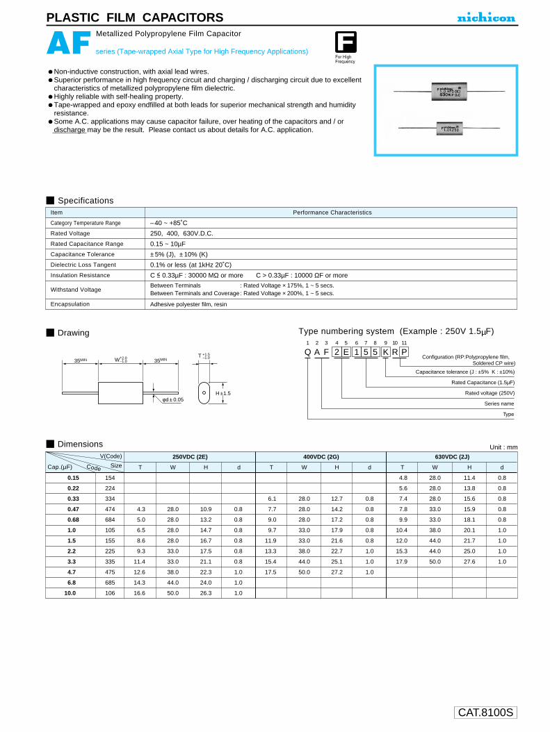
PLASTIC FILM CAPACITORS
Non-inductive construction, with axial lead wires.Superior performance in high frequency circuit and charging / discharging circuit due to excellent characteristics of metallized polypropylene film dielectric.Highly reliable with self-healing property.Tape-wrapped and epoxy endfilled at both leads for superior mechanical strength and humidity resistance.Some A.C. applications may cause capacitor failure, over heating of the capacitors and / or discharge may be the result. Please contact us about details for A.C. application.
AF series (Tape-wrapped Axial Type for High Frequency Applications)
Metallized Polypropylene Film Capacitor
Drawing
Specifications
Category Temperature Range
Rated Voltage
Rated Capacitance Range
Capacitance Tolerance
Insulation Resistance
Dielectric Loss Tangent
Withstand Voltage
Encapsulation
–40 ~ +85˚C
250, 400, 630V.D.C.
0.15 ~ 10µF
±5% (J), ±10% (K)
0.1% or less (at 1kHz 20˚C)
C <= 0.33µF : 30000 MΩ or more C > 0.33µF : 10000 ΩF or more
Between Terminals : Rated Voltage × 175%, 1 ~ 5 secs.Between Terminals and Coverage : Rated Voltage × 200%, 1 ~ 5 secs.
Adhesive polyester film, resin
Performance CharacteristicsItem
Q1
A2
F3
24
E5
16
57
58
K9
R10
P11
Configuration (RP:Polypropylene film, Soldered CP wire)
Capacitance tolerance (J : ±5% K : ±10%)
Rated Capacitance (1.5µF)
Rated voltage (250V)
Series name
Type
W+2.0
–1.0
+1.5
–1.0T
35MIN 35MIN
φd ± 0.05H ±1.5
Dimensions Unit : mm
Type numbering system (Example : 250V 1.5µF)
V(Code) 250VDC (2E) 400VDC (2G) 630VDC (2J)
Cap. .(µF) Size T W H d T W H d T W H d
0.15 154 4.8 28.0 11.4 0.8
0.22 224 5.6 28.0 13.8 0.8
0.33 334 6.1 28.0 12.7 0.8 7.4 28.0 15.6 0.8
0.47 474 4.3 28.0 10.9 0.8 7.7 28.0 14.2 0.8 7.8 33.0 15.9 0.8
0.68 684 5.0 28.0 13.2 0.8 9.0 28.0 17.2 0.8 9.9 33.0 18.1 0.8
1.0 105 6.5 28.0 14.7 0.8 9.7 33.0 17.9 0.8 10.4 38.0 20.1 1.0
1.5 155 8.6 28.0 16.7 0.8 11.9 33.0 21.6 0.8 12.0 44.0 21.7 1.0
2.2 225 9.3 33.0 17.5 0.8 13.3 38.0 22.7 1.0 15.3 44.0 25.0 1.0
3.3 335 11.4 33.0 21.1 0.8 15.4 44.0 25.1 1.0 17.9 50.0 27.6 1.0
4.7 475 12.6 38.0 22.3 1.0 17.5 50.0 27.2 1.0
6.8 685 14.3 44.0 24.0 1.0
10.0 106 16.6 50.0 26.3 1.0
Code

CAT.8100S
10± 0.1
2-2φ±0.1
(Terminal dimensions) (PC board hole dimensions)
4.0±
0.5
2.5
1.5
0.8
+0.2-0.1
+0.2
-0.10.8 +0.2
-0.1
L1
A2
K3
24
D5
66
87
18
M9
H10
L11
A12
513
014 15 16
Configuration
Case dia. code
Case length code
Bottom Plate
Rated Capacitance (680µF)
Rated voltage (200V)
Series name
Type
φD
22
25
30
35
Code
Z
A
B
C
BP
code less
With BottomPlate
WithoutBottom Plate
Capacitance tolerance (±20%)
Polarity bar
10L±2
φD +1
MAX
.
4.0±0.5
Bottom plate (code BP only)
Pressure relief vent
Sleeve (P.V.C.)
Please contact to us if Eco-Products are required.
ALUMINUM ELECTROLYTIC CAPACITORS
AK series
Snap-in Terminal Type, Permissible Abnormal Voltage,Wide Temperature Range
Withstanding 2000 hours application of ripple current at 105°C.Extended voltage range at 200V, 400V and 420V.Improved safety features for abnormally excessive voltage.Ideally suited for the equipment used at voltage fluctuating area.
Drawing
Specifications
Category Temperature Range
Rated Voltage Range
Rated Capacitance Range
Capacitance Tolerance
Leakage Current
tan δ
Stability at Low Temperature
Endurance
Shelf Life
Safety Performance
Marking
Performance CharacteristicsItem
– 25 ~ +105°C
200 • 400 • 420V
33 ~ 1200µF
±20% at 120Hz, 20°C
Printed with white color letter on dark blue sleeve
After an application of DC voltage (in the range of ratedDC voltage even after over-lapping the specified ripplecurrent) for 2000 hours at 105°C, capacitors meetthe characteristic requirements listed at right.
After leaving capacitors under no load at 105°C for 1000 hours, they meet the requirements listed at right.
Type numbering system (Example : 200V 680µF)
AK
AQ
Smaller
I (µA) (After 5 minutes' application of rated voltage) [C : Rated Capacitance (µF),V : Voltage(V)]
0.20MAX. 120Hz 20°C
Rated voltage(V)Impedance ratio Z—25°C/Z+20°C
2008
400 • 4208
Measurement frequency : 120Hz
The pressure relief vent will operate in normal conditions, with no dangerous conditions such as flames, ignitions or dispersion of pieces of the capacitor and/or case.rating
Voltage (V)
200
400
420
Capacitance (µF) 330 C < 330330 C < 470470 C < 470330 C < 100100 C < 220220 C < 470330 C < 100100 C < 220220 C < 470
Limited DC current Test voltage4 A5 A7 A2 A4 A7 A2 A4 A7 A
300VDC and 375VDC
500VDC and 600VDC
520VDC and 630VDC
test conditions
Capacitance change
Leakage current
tan δWithin ±20% of initial value
Initial specified value or less
200% or less of initial specified value
Capacitance change
Leakage current
tan δWithin ±15% of initial value
Initial specified value or less
150% or less of initial specified value
3 CV
Minimum order quantity : 50pcs.
Dimension table in next page.

CAT.8100S
AK series
ALUMINUM ELECTROLYTIC CAPACITORS
Dimensions
Rated Ripple (A rms) at 105°C 120Hz
D × L (mm)
33
39
47
56
68
82
100
120
150
180
220
270
330
390
470
560
680
820
1000
1200
330
390
470
560
680
820
101
121
151
181
221
271
331
391
471
561
681
821
102
122
22
22 × 200.35
22 × 200.50
22 × 250.70
22 × 250.74
22 × 300.90
22 × 301.05
22 × 351.20
22 × 401.30
22 × 451.50
25
25 × 200.65
25 × 250.85
25 × 301.05
25 × 301.20
25 × 351.30
25 × 401.50
25 × 501.70
30
30 × 200.70
30 × 251.05
30 × 251.20
30 × 251.35
30 × 351.55
30 × 401.70
30 × 451.99
30 × 502.10
35
35 × 201.10
35 × 251.55
35 × 301.70
35 × 351.99
35 × 402.10
35 × 502.30
2222 × 20
0.2222 × 20
0.3022 × 25
0.3522 × 25
0.3822 × 25
0.4022 × 30
0.5022 × 35
0.5522 × 40
0.6022 × 45
0.7022 × 50
0.80
25
25 × 200.35
25 × 200.38
25 × 250.45
25 × 250.50
25 × 300.53
25 × 300.60
25 × 350.70
25 × 400.80
25 × 450.90
30
30 × 200.40
30 × 200.50
30 × 200.50
30 × 250.53
30 × 250.60
30 × 300.70
30 × 300.80
30 × 350.90
30 × 400.98
30 × 501.21
35
35 × 200.55
35 × 250.70
35 × 250.80
35 × 300.90
35 × 350.96
35 × 401.21
35 × 451.32
35 × 501.45
2222 × 25
0.25
22 × 250.35
22 × 250.38
22 × 300.45
22 × 350.64
22 × 400.69
22 × 450.75
25
25 × 250.45
25 × 300.64
25 × 300.69
25 × 350.75
25 × 400.82
25 × 450.90
30
30 × 250.69
30 × 300.75
30 × 300.82
30 × 350.90
30 × 401.00
30 × 451.10
35
35 × 250.75
35 × 250.82
35 × 300.90
35 × 351.00
35 × 401.10
35 × 451.20
Case sizeRated ripple
200V (2D) 400V (2G) 420V (W6) V(Code)
φDCodeCap.(µF)
Frequency coefficient of rated ripple currentFrequency (Hz)
200V400•420V
Coefficient
500.850.88
600.880.90
1201.001.00
1k1.151.10
10k~1.201.15
CAT.8100S
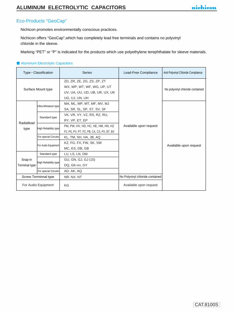
ZD, ZR, ZE, ZG, ZS, ZP, ZT
WX, WP, WT, WF, WG, UP, UT
UV, UA, UU, UD, UB, UR, UX, UK
UG, UJ, UN, UH
MA, ML, MP, MT, MF, MV, MJ
SA, SR, SL, SP, ST, SV, SF
VK, VR, VY, VZ, RS, RZ, RU,
RY, VP, ET, EP
PM, PW, HV, HD, HC, HE, HM, HN, HZ
PJ, PS, PV, PT, PZ, PB, CA, CS, PX, BT, BX
KL, TM, SH, HA, JB, AQ
KZ, FG, FX, FW, SK, SW
MC, ES, DB, GB
LU, LS, LN, DM
GU, GN, GJ, GJ (15)
DQ, GK-HH, GY
AD, AK, AQ
NR, NX, NT
KGFor Audio Equipment Available upon request
Eco-Products “GeoCap”
Nichicon promotes environmentally conscious practices.
Nichicon offers “GeoCap”,which has completely lead free terminals and contains no polyvinylchloride in the sleeve.
Marking “PET” or “P” is indicated for the products which use polyethylene terephthalate for sleeve materials.
Radiallead
type
Snap-in
Terminal type
Surface Mount type
Type • Classification Series Lead-Free Compliance Anti Polyvinyl Chloride Compliance
Standard type
High Reliability type
For special Circuits
For Audio Equipment
Ultra-Miniature type
Standard type
High Reliability type
For special Circuits
Available upon request
No Polyvinyl chloride containedScrew Terminnal type
Aluminum Electrolytic Capacitors
No polyvinyl chloride contained
Available upon request
ALUMINUM ELECTROLYTIC CAPACITORS

CAT.8100S
ALUMINUM ELECTROLYTIC CAPACITORS
1. Circuit Design(1) Please make sure the environmental and mounting conditions to which the capacitor will be exposed to are within the conditions specified
in Nichicon's catalog (or alternate Nichicon specifications, such as series drawings).
(2) Operating temperature and applied ripple current must be within Nichicon specification.qThe capacitor must not be used in an ambient temperature which exceeds the operating temperature specified in the Nichicon catalog.w Do not apply excessive current which exceeds the rated ripple current.
(3) Appropriate capacitors which comply with the life requirement of the products should be selected when designing the circuit.
(4) Aluminum electrolytic capacitors are polarized. Do not apply reverse voltage or AC voltage. Please use bi–polarized capacitors for acircuit that can possibly see reversed polarity.Note: Even bi–polarized capacitors can not be used for AC voltage application.
(5) It is necessary to use a properly designed aluminum electrolytic capacitor for applications that capacitors are rapidly charged/discharged.The following are given as “rapid charge/discharge” applications. Welding machine, photo flash and servo motor control unit. Pleasecontact us when capacitors are to be used in such a circuit.
(6) Do not apply excess voltage.q Please pay attention so that the peak voltage, which is DC voltage overlapped by ripple current, will not exceed the rated voltage.w In the case where more than 2 aluminum electrolytic capacitors are used in series, please make sure that applied voltage will be lower
than rated voltage and the voltage be will applied to each capacitor equally using a balancing resistor in parallel with the capacitor.
(7) Aluminum electrolytic capacitors must be electrically isolated as follows, since the aluminum case of aluminum electrolytic capacitors iselectrically connected to cathode foil through unstable resistance contained on naturally formed oxide layer of the aluminum case andelectrolytes’ resistance. q(a) Case and negative terminal (except axial leaded part such as JIS configuration 02 type)
(b) Case and positive terminal(c) Case and circuit pattern
w(a)Blank terminal of can type such as JIS configuration693, 694 or 695 and negative and positive terminal,including the circuit pattern.
(8) Outer sleeve of the capacitor is not guaranteed as an electrical insulator. Do not use a standard sleeve on a capacitor in applications thatrequire the electrical insulation. When the application requires special insulation, please contact our sales office for details.
(9) Capacitors must not be used under the following conditions:q(a) Capacitors must not be exposed to water (including
condensation), brine or oil.(b) Ambient conditions that include toxic gases such as
hydrogen sulfide, sulfurous acid, nitrous acid, chlorine, ammonium, etc..
(c)Ambient conditions that expose the capacitor to ozone, ultraviolet ray and radiation.
wSevere vibration and physical shock conditions that exceed Nichicon specifications.Vibration:Test condition• vibration frequency range : 10 ~ 55 ~ 10Hz• sweep rate : 10 ~ 55 ~ 10Hz / minute• sweep method : logarithmic• amplitude or acceleration : 1.5mm (max.acceleration is 10G)• direction of vibration : X, Y, Z direction• testing time : 2 hours per each direction
Shock is not applicable normally.If a particular condition is required, Please contact to our sales office.
(10) When designing a circuit board, Please pay attention to following:qMake the hole spacing on the P.C. board match the lead space of the capacitor.wThere should not be any circuit pattern or circuit wire above the capacitor pressure relief vent.eUnless otherwise specified, following clearance should be made above the pressure relief vent.
APPLICATION GUIDELINESFOR ALUMINUMELECTROLYTIC CAPACITORS
Case Diameter Gap Requiredφ6.3 ~ 16 2mm or moreφ18 ~ 35 3mm or moreφ40 or more 5mm or more
CAT.8100S
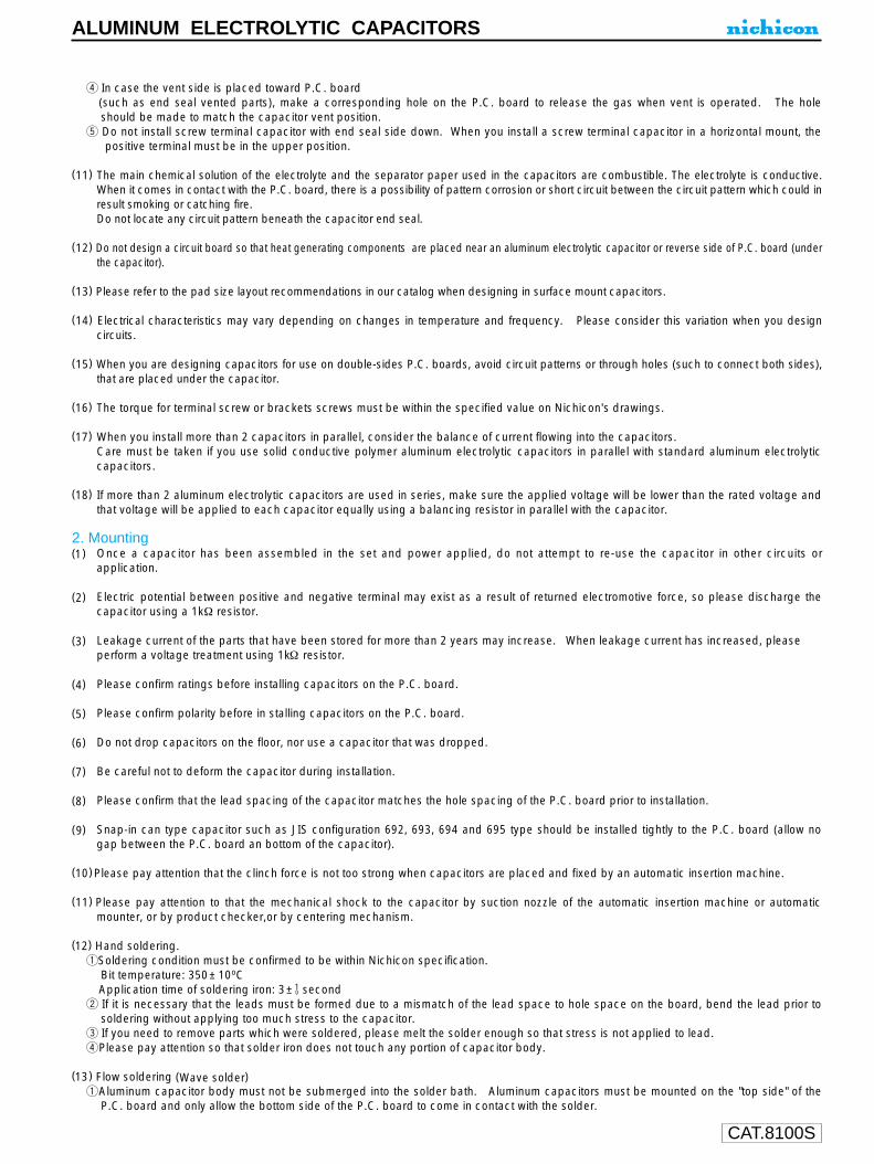
ALUMINUM ELECTROLYTIC CAPACITORS
r In case the vent side is placed toward P.C. board(such as end seal vented parts), make a corresponding hole on the P.C. board to release the gas when vent is operated. The holeshould be made to match the capacitor vent position.
t Do not install screw terminal capacitor with end seal side down. When you install a screw terminal capacitor in a horizontal mount, thepositive terminal must be in the upper position.
(11) The main chemical solution of the electrolyte and the separator paper used in the capacitors are combustible. The electrolyte is conductive.When it comes in contact with the P.C. board, there is a possibility of pattern corrosion or short circuit between the circuit pattern which could inresult smoking or catching fire.Do not locate any circuit pattern beneath the capacitor end seal.
(12) Do not design a circuit board so that heat generating components are placed near an aluminum electrolytic capacitor or reverse side of P.C. board (underthe capacitor).
(13) Please refer to the pad size layout recommendations in our catalog when designing in surface mount capacitors.
(14) Electrical characteristics may vary depending on changes in temperature and frequency. Please consider this variation when you designcircuits.
(15) When you are designing capacitors for use on double-sides P.C. boards, avoid circuit patterns or through holes (such to connect both sides),that are placed under the capacitor.
(16) The torque for terminal screw or brackets screws must be within the specified value on Nichicon's drawings.
(17) When you install more than 2 capacitors in parallel, consider the balance of current flowing into the capacitors.Care must be taken if you use solid conductive polymer aluminum electrolytic capacitors in parallel with standard aluminum electrolyticcapacitors.
(18) If more than 2 aluminum electrolytic capacitors are used in series, make sure the applied voltage will be lower than the rated voltage andthat voltage will be applied to each capacitor equally using a balancing resistor in parallel with the capacitor.
2. Mounting(1) Once a capacitor has been assembled in the set and power applied, do not attempt to re-use the capacitor in other circuits or
application.
(2) Electric potential between positive and negative terminal may exist as a result of returned electromotive force, so please discharge thecapacitor using a 1kΩ resistor.
(3) Leakage current of the parts that have been stored for more than 2 years may increase. When leakage current has increased, pleaseperform a voltage treatment using 1kΩ resistor.
(4) Please confirm ratings before installing capacitors on the P.C. board.
(5) Please confirm polarity before in stalling capacitors on the P.C. board.
(6) Do not drop capacitors on the floor, nor use a capacitor that was dropped.
(7) Be careful not to deform the capacitor during installation.
(8) Please confirm that the lead spacing of the capacitor matches the hole spacing of the P.C. board prior to installation.
(9) Snap-in can type capacitor such as JIS configuration 692, 693, 694 and 695 type should be installed tightly to the P.C. board (allow nogap between the P.C. board an bottom of the capacitor).
(10)Please pay attention that the clinch force is not too strong when capacitors are placed and fixed by an automatic insertion machine.
(11) Please pay attention to that the mechanical shock to the capacitor by suction nozzle of the automatic insertion machine or automaticmounter, or by product checker,or by centering mechanism.
(12) Hand soldering.qSoldering condition must be confirmed to be within Nichicon specification.
Bit temperature: 350±10oCApplication time of soldering iron: 3± 0
1 secondw If it is necessary that the leads must be formed due to a mismatch of the lead space to hole space on the board, bend the lead prior to
soldering without applying too much stress to the capacitor.e If you need to remove parts which were soldered, please melt the solder enough so that stress is not applied to lead.rPlease pay attention so that solder iron does not touch any portion of capacitor body.
(13) Flow soldering (Wave solder)qAluminum capacitor body must not be submerged into the solder bath. Aluminum capacitors must be mounted on the "top side" of the
P.C. board and only allow the bottom side of the P.C. board to come in contact with the solder.

CAT.8100S
wSoldering condition must be confirmed to be within Nichicon specification.Solder temperature: 260±5°C Immersing lead time:10±1 second Thickness of P.C. board : 1.6mm
ePlease avoid having flux adhere to any portion except the terminal.rPlease avoid contact between other components and the aluminum capacitor.
(14) Reflow soldering (SMD only)qSoldering condition must be confirmed to be within Nichicon specification.
Pre-heationg : Less than 150°C, 90 seconds max.Max. temperature at capacitor top during reflow : 230°CThe duration for over 200°C temperature at capacitor top: 20 seconds max.The duration from the pre-heat temperature to peak temperature of reflow varies due to changes of the peak temperature. Refer to page17 for details.
wWhen an infrared heater is used, please pay attention to the extent of heating since the absorption rate of infrared, will vary due todifference in the color of the capacitor body, material of the sleeve and capacitor size.
eThe number of reflow time for SMD aluminum electrolytic capacitors shall be one time. If this type of capacitor has to be inevitablysubjected to the reflow twice, enough cooling time between the first and second reflow (at least more than 30 minutes) shall be taken toavoid consecutive reflow. Please contact our sales office if you have questions.
(15)Do not tilt lay down or twist the capacitor body after the capacitor are soldered to the P.C. board.
(16)Do not carry the P.C. board by grasping the soldered capacitor.
(17)Please do not allow anything to touch the capacitor after soldering. If P.C. board are stored in stack, please make sure P.C. board or theother components do not touch the capacitor.The capacitors shall not be effected by any radiated heat from the soldered P.C. board or other components after soldering.
(18) CleaningqDo not clean capacitors with halogenated cleaning agent. However, if it is necessary to clean with halogenated cleaning agent, use
cleaning proof capacitors but within the range specified in the specification.wRecommeded cleaning method
Applicable : Any type, any ratingsCleaning agents : Pine Alpha ST–100S, Clean Through 750H/750L/710M, Sanelek B–12, Aqua Cleaner 210SEP,Techno Care
FRW14 ~ 17, lso-propyl AlcoholCleaning conditions : Total cleaning time shall be within 5
minutes by immersion,ultrasonic or other method. (Temperature of the cleaning agent shall be 60°C or lower.)Aftercleaning, capacitors should be dried using hot air for minimum of 10 minutes along with the PC board. Hot airtemperature should be below the maximum operating temperature of the capacitor. Insufficient dries dry after waterrinse may cause appearance problems, sleeve shrink, bottom-plate bulge and such.It is recommended to monitorconductivity, pH,and concentration of the agent.Please do NOT keep a product after cleaning in condition thatcleaning agents exists as steam,or in non ventilated containers.
eCFC substituteThe capacitors can be cleaned using AK-225AES as shown in table below. Please monitor contamination of solution by measuringconductivity, pH, specific gravity, water content and such. Do not store capacitors in a cleaning agent atomosphere or sealed containerafter cleaning.
ALUMINUM ELECTROLYTIC CAPACITORS

CAT.8100S
rAvoid using ozone depleting substances for cleaning agents to concern about global environment.tPlease consult us when using Cleaning Agents and /or cleaning conditions except aforementioned.
(19) Fixing materials and coating materialsqDo not use any ingredients which contain halogen.wPlease pay attention to remove flux and any contamination which remains in the gap between the end seal and P.C.
board and dry that portion well before coating.ePlease do not apply any material all around the capacitor body but apply it partially.rPlease contact our sales office to make sure whether the curing condition of coating material would cause any problems.
(20) Regarding repellent processBe aware that halogen compound such as methyl bromide may be contained in repellent chemicals used during insects proofingprocess. The following cases can cause corrosive reaction to aluminum electrolytic capacitors if halogens are contained in thechemical. (1)A completed unit or individual capacitors are directly steamed with the chemical.(2)Lumber that has been treated with thechemical is used in the packaging process.
(21) Notification on Disinfection due to SARSqInfluence caused by harmful ingredients/substances of disinfectants :
Some disinfectants contain halongenide such as fluorine, Chlorine, bromine, iodine etc. , and acid or alkali solutions. Please do not usethe disinfectants which contain any substances as above-mentioned in a location where capacitors may be subjected to them.Halogens contained in the disinfectants can particularly cause corrosive reactions to aluminum electrolytic capacitors, such as reductionof capacitance, open circuit and so on as time goes by. Therefore, if the disinfectants containing the above-mentioned substances areused at the place where capacitors are exposed and may become with them, Please be sure to dry the solution completely fromcapacitors.
wIn case you have already used some disinfectants containing halogenide, acid or alkai solution in the work place :lf you have already used some disinfectants containing halogenide, acid or alkai solution, Please lnform us what kind of disinfectants andunder what conditions you used. Upon request, we will advise you of the possible effect the soltion will have on the capacitors.
Please note that even when disinfectants do not touch capacitors directly, vaporized ingredients and substances contained in them canpotentially adhere to and exert a harmful influence upon capacitors.
An influence may vary from differing conditions as to how much disinfectant is adhering or spreading over capacitors.As long as the capacitors cannot be completely sealed or isolated but has a chance to come in contact with trace amounts of thesedisinfectants, please evaluate and check the capacitors for confirmation.
3. In the equipment(1) Do not directly touch terminal by hand.
Min
iatu
re T
ype
AK-225AES
Applicable Series
Cleaning Agent
Chip (SMD) Type
Ultra-Miniature Type
Standard Products
High-Reliability Type
For Special Circuit
For Audio Use
ZD, ZR, ZE, ZG, ZS, ZP, WX,WP, WT, WF, WG, UP, UT, UA,UU, UD, UR, UX, UK, UN, UHUG (Less than 100V)UJ (Less than 100V)
MA, MP, ML, MT, MF, MJ,
SA, SR, SL, SP, ST, SF
VK (Less than 100V)VR (Less than 100V)VY (Less than 100V)VZ (Less than 100V)RS (Less than 100V)RZ (Less than 100V)RU(Less than 100V)RY (Less than 100V),VP, ET, EP
PM (Less than 100V)PW (Less than 100V)HV, HD, HC, HE, HM, HN, HZPJ (Less than 100V)PS (Less than 100V)PV,PX PB (Less than 100V),BT (Less than 100V), BX
KL, TM, SH, HA, JBVX 02 type (Less than 100V)
KZ, FG, FX, FW, SK, SW, MC,ES, DB, GB
Standard Products LS (Less than 100V)
High-Reliability Type
Within 5 minutes, total cleaning time by immersion, vaporspray, or ultrasonic and such. For SMD andultra-miniature type, within 2 minutes total cleaning time.(Temp. of agent: 40°C or below)
CleaningConditions
GU (Less than 100V)GK-HH (Less than 100V)Lar
ge Ca
n Type
ALUMINUM ELECTROLYTIC CAPACITORS

CAT.8100S
CapacitanceCode
(µF)0.1 0R10.47 R47
1 0102.2 2R222 220220 221
2200 22222000 223
Rated Surgevoltage voltage Code
(V) (V)4.0 5.0 0G5.5 6.30 0L6.3 8.0 0 J
10.0 13.0 1A16.0 20.0 1C25.0 32.0 1E35.0 44.0 1V50.0 63.0 1H63.0 79.0 1J80.0 100.0 1K
100.0 125.0 2A110.0 2Q
Cap. Tol.Code
(%)±10 K±20 M
–10 ~ +30 Q–10 ~ +50 T
Special A
Rated Surgevoltage voltage Code
(V) (V)125 2B160 200 2C180 225 2Z200 250 2D220 270 2P250 300 2E315 365 2F350 400 2V400 450 2G420 470 W6450 500 2W500 550 2H550 600 2L
Chip type
Radial lead typeU
(CE32)
Axial lead typeT(CE02)
Can type
(CE621,622,692, L
694,695,331)
ALUMINUM ELECTROLYTIC CAPACITORS
(2) Do not short between terminals by conductor, nor spill conductible liquid such as alkaline or acidic solution on or near the capacitor.
(3) Please make sure that the ambient conditions where the set is installed will be free from spilling water or oil, direct sunlight, ultraviolet rays,radiation, poisonous gases, vibration or mechanical shock.
4. Maintenance and Inspection(1) Please periodically inspect the aluminum capacitors that are installed in industrial equipment. The following items should be checked:
qAppearance : Remarkable abnormality such as vent operation, leaking electrolyte etc.wElectrical characteristic: Capacitance, dielectric loss tangent, leakage current etc., which are specified in the drawing exchanged
between Nichicon and our customers or the Nichicon catalog.
5. In an Emergency(1) If you see smoke due to operation of safety vent, turn off the main switch or pull out the plug from the outlet.
(2) Do not draw your face the safety vent since gas which in over 100°C will be emitted when the safety vent operates.If the gas has entered your eyes, please flush your eyes immediately in pure water.If you breathed the gas, immediately wash out your mouth and throat with water.Do not ingest electrolyte. If your skin is exposed to electrolyte, please wash it away using soap and water.
6. Storage(1) Do not keep capacitor in high temperature and high humidity.
Storage ambient should be:Temperature : 5°C ~ 35°C, Humidity : lower than 75%.Place: Indoor
(2) Avoid ambient conditions: where capacitors can be covered with water, brine or oil.
(3) Avoid ambient conditions: where capacitors are exposed poisonous gases such as hydrogen sulfide, sulfurous acid, nitrous acid, chlorine,ammonium etc.
(4) Do not keep capacitor in conditions, that expose the capacitor to ozone, ultraviolet ray or radiation
7. Disposal(1) Please dispose capacitors in either of the following ways :
q Incinerate capacitors after crushing parts of making a hole on the capacitor body.w Bury capacitors in the ground. Please have a disposal specialist do it.
The above mentioned material is according to EIAJRCR–2367B (issued in March, 2002), titled “Guideline of notabilia for fixed aluminum electrolytic capacitors for use in electronic equipment”. Please refer to the book for details.
Type numbering system
1 2 3 4 5 6 7 8 9 10 11 12 13 14
Type Series name Rated voltage Capacitance Capacitance Configuration Sizetolerance code
See pages
6 ~ 8.See pages
24 ~ 208
See pages
24 ~ 208
A.C. rated voltage only.
Taped,lead cut / formedSee pages19 ~ 21
For Eco-products of
chip or miniature
aluminum electrolytic
capacitors, following
code will be put at
11th dight of type
numbering system
Specificationcode
Large Can Type
MiniatureType

CAT.8100S
Category Temperature RangeRated Voltage RangeRated Capacitance RangeCapacitance ToleranceLeakage Current
tan δ
Stability at Low Temperature
Endurance
Shelf Life
Safety Performance
Marking Printed with white color letter on dark brown sleeve.
Performance CharacteristicsItem–40 ~ +105°C200 · 400V10 ~ 220µF±20% at 120Hz, 20°C
Measurement frequency:120Hz, Temperature:20°C
Measurement frequency : 120Hz
After leaving capacitors under no load at 105°C for 1000 hours, they meet the specified value for endurance characteristics listed above.The pressure relief vent will operate in normal conditions, with no dangerous conditons such as flames, ignitions or dispersion of pieces of the capacitor and / or case.
After 1 minute's application of rated voltage, leakage current is 0.04CV+100 (µA) or less.
After an application of D.C. bias voltage plus the rated ripplecurrent for 2000 hours at 105°C the peak voltage shall notexceed the rated D.C. voltage, capacitors meet thecharacteristic requirements listed at right.
ALUMINUM ELECTROLYTIC CAPACITORS
Improved safety feature for abnormally excessive voltage.High ripple current product.
Specifications
Type numbering system (Example : 200V 100µF)
AQ (Radial Lead Type) series
Wide Temperature Range, Miniature Type Permissible Abnormal Voltage
φD
P
10
0.5
5.0
φd 0.6
12.5
0.5
5.0
0.6
16
0.5
7.5
0.8
18
0.5
7.5
0.8
22
1.0
10
1.0
U1
A2
Q3
24
D5
16
07
18
M9
H10
D11 12
Configuration
Capacitance tolerance (±20%)
Rated Capacitance (100µF)
Rated voltage (200V)
Series name
Type
(φD 18) 2.0 (φD >18) 3.0
Case size
L+ MAX 15MIN 4MIN
φd
φD+
M
AX
P±0
.5
Pressurerelief vent
In case L>25 for φ12.5 (D) case sizes, lead diameter φ0.8 (d) will be applied.
Sleeve (P.E.T.)
φ D
10
Pb free lead finishingPb free PET sleeve
Sn-Pb lead finishingPVC sleeve contain Pb
PD PH
HH12.5 ~ 18 HD
22 RD RH
Configuration
Please contact to us if other configurations are required.
Radial Lead Type
Frequency coefficient of rated ripple current
FrequencyCoefficient
50, 60Hz 120Hz 300Hz 1kHz 10kHz ~0.80 1.00 1.25 1.40 1.60
010
022
033
047
056
068
082
100
150
180
220
100
220
330
470
560
680
820
101
151
181
221
10 × 20120
10 × 25160
0.10 × 31.5195
12.5 × 20.0160
12.5 × 20.0195
12.5 × 25.0210
12.5 × 25.0250
12.5 × 31.5285
12.5 × 35.5335
16 × 20285
16 × 25335
0.16 × 31.5435
0.16 × 35.5495
18 × 20335
18 × 25435
18 × 31.5495
0.18 × 35.5575
22 × 2043522 × 25495
12.5 × 20.0100
12.5 × 31.5145
12.5 × 40.0195
16 × 20145
16 × 25195
0.16 × 35.5280
0.16 × 35.5320
16 × 40350
18 × 20195
18 × 25280
18 × 31.5320
18 × 35.5350
18 × 40420
22 × 20280
22 × 25320
200 (2D) 400 (2G)10 12.5 16 18 22 12.5 16 18 22φD
Dimensions
Case sizeRated ripple
D × L (mm)
V(Code)
CodeCap.(µF)
Rated Ripple (mA rms) at 105°C 120Hz : In case of low profile type, 6 will be put at 12th digit of type numbering system.
: For further low profile product, 3 will be put at 12th digit.
Rated voltage (V)
tan δ (MAX.)
2000.15
4000.15
Z–25°C / Z+20°CZ–40°C / Z+20°C
Rated voltage (V)
Impedance ratio ZT / Z20 (MAX.)
20036
400810
Capacitance change
Leakage current
tan δWithin ±20% of initial value
Initial specified value or less200% or less of initial specified value
voltage (V)Test conditions
200 400
Limited DC current
4A
2A
Test Voltage
300VDC and 375VDC
500VDC and 600VDC
Please refer to page 19, 20, 21 about the formed or taped product spec.Please refer to page 3 for the minimum order quantity.

CAT.8100S
(Terminal dimensions) (PC board hole dimensions)
L1
A2
Q3
24
D5
66
87
18
M9
H10
L11
A12
413
014 15 16
Configuration
Case dia. code
Case length code
Bottom Plate
Rated Capacitance (680µF)
Rated voltage (200V)
Series name
Type
φD
22
25
30
35
Code
Z
A
B
C
BP
code less
With BottomPlateWithoutBottom Plate
Capacitance tolerance (±20%)
10±0.1
2-2 φ
4.0±
0.5
2.5
1.5
0.8
+0.2-0.1
+0.2
-0.10.8 +0.2
-0.1
Polarity bar
10L±2
φD +1
MAX
.
4.0±0.5Pressure relief vent
Bottom plate (code BP only)
±0.1
Sleeve (P.V.C.)
Please contact to us if Eco-Products are required.
Drawing Type numbering system (Example : 200V 680µF)
ALUMINUM ELECTROLYTIC CAPACITORS
AQ (692 type) series
Snap-in Terminal Type, Permissible Abnormal Voltage, Smaller-sized,Wide Temperature Range
Withstanding 2000 hours application of ripple current of 105°C.Extended voltage range at 200V, 220V and 400V.Smaller case sizes and higher ripple current than AK series.Improved safety features for abnormally excessive voltage.Ideally suited for the equipment used at voltage fluctuating area.
Specifications
Category Temperature Range
Rated Voltage Range
Rated Capacitance Range
Capacitance Tolerance
Leakage Current
tan δ
Stability at Low Temperature
Endurance
Shelf Life
Safety Performance
Marking
Performance CharacteristicsItem
–25 ~ +105°C
200 • 220V • 400V
33 ~ 1500µF
±20% at 120Hz, 20°C
0.20MAX. 120Hz, 20°C
Printed with white color letter on dark blue sleeve
After an application of DC voltage (in the range of ratedDC voltage even after over-lapping the specified ripplecurrent) for 2000 hours at 105°C, capacitors meetthe characteristic requirements listed at right.
After leaving capacitors under no load at 105°C for 1000 hours, they meet the requirements listed at right.
The pressure relief vent will operate in normal conditions, with no dangerous conditions such as flames, ignitions or dispersion of pieces of the capacitor and / or case.Rating
Voltage (V)
200
Rated Capacitance (µF)330 C < 330330 C < 470470 C < 470
Limited DC current Test voltage4 A5 A7 A
300VDC and 375VDC
Test conditions
AQ
AKSmaller
I (µA) (After 5 minutes' application of rated voltage) [C : Rated Capacitance (µF),V : Voltage(V)]
Rated voltage(V)Impedance ratio Z—25°C/Z+20°C
200 • 2208
4008
Measurement frequency : 120Hz
220330 C < 330330 C < 470470 C < 470
4 A5 A7 A
320VDC and 405VDC
400330 C < 100100 C < 220220 C < 470
2 A4 A7 A
500VDC and 600VDC
Capacitance change
Leakage current
tan δWithin ±20% of initial value
Initial specified value or less
200% or less of initial specified value
Capacitance change
Leakage current
tan δWithin ±15% of initial value
Initial specified value or less
150% or less of initial specified value
Minimum order quantity : 50pcs.
3 CV
Dimension table in next page.

CAT.8100S
AQ series
ALUMINUM ELECTROLYTIC CAPACITORS
Dimensions
Rated Ripple (A rms) at 105°C 120 Hz
D × L (mm)
0033
0039
0047
0056
0068
0082
0100
0120
0150
0180
0220
0270
0330
0390
0470
0560
0680
0820
1000
1200
1500
330
390
470
560
680
820
101
121
151
181
221
271
331
391
471
561
681
821
102
122
152
22 × 250.70
22 × 250.90
22 × 251.00
22 × 301.20
22 × 351.35
22 × 401.45
22 × 451.60
22 × 501.75
22
25 × 200.70
25 × 251.20
25 × 301.35
25 × 301.45
25 × 351.60
25 × 401.75
25 × 502.11
25
30 × 251.45
30 × 301.60
30 × 301.75
30 × 352.11
30 × 452.40
30 × 502.65
30
35 × 251.75
35 × 302.11
35 × 352.40
35 × 402.65
35 × 453.08
35 22 25 30 35200V (2D) 220V (2P)
φD 22
25 × 200.65
25 × 250.70
25 × 250.90
25 × 301.00
25 × 301.20
25 × 351.35
25 × 401.45
25 × 451.60
22 × 200.50
22 × 250.60
22 × 250.65
22 × 250.70
22 × 300.90
22 × 351.00
22 × 401.20
22 × 451.35
25
30 × 200.90
30 × 251.00
30 × 251.20
30 × 301.35
30 × 301.45
30 × 351.60
30 × 401.75
30 × 452.11
30
35 × 201.00
35 × 251.20
35 × 251.35
35 × 251.45
35 × 301.60
35 × 351.75
35 × 402.11
35 × 452.40
35400V (2G)
22 × 250.25
22 × 250.30
22 × 250.35
22 × 250.45
22 × 250.51
22 × 300.58
22 × 300.66
22 × 350.76
22 × 400.85
25 × 250.58
25 × 250.66
25 × 300.76
25 × 350.85
25 × 400.95
25 × 451.24
30 × 250.76
30 × 250.85
30 × 300.95
30 × 351.24
30 × 401.30
30 × 451.47
35 × 250.95
35 × 301.24
35 × 351.30
35 × 351.47
35 × 401.59
35 × 451.87
Case sizeRated ripple
V(Code)
CodeCap.(µF)
Frequency coefficient of rated ripple currentFrequency (Hz)
200•220V400V
Coefficient
500.850.88
600.880.90
1201.001.00
1k1.151.10
10k~1.201.15

CAT.8100S
PLASTIC FILM CAPACITORS
Non-inductive construction, compact size, metallized film capacitor with axial lead wires.Highly reliable with self-healing property.Minimum loss at high frequency.Tape-wrapped and epoxy endfilled at both leads for superior mechanical strength and humidity resistance.High capacitance value, offering a wide variety of applications.
ApplicationsFiltering DC-blocking, coupling and so on of general communications equipment and use inAC circuits for motor starting, charging / discharging, lighting, etc.Some A.C. applications may cause capacitor failure, over heating of the capacitors and/or discharge may be theresult. Please contact us about details for A.C. application.
AS series (Tape-wrapped Axial Compact Type)
Metallized Polyester Film Capacitor
Drawing
Specifications
Category Temperature Range
Rated Voltage
Rated Capacitance Range
Capacitance Tolerance
Dielectric Loss Tangent
Insulation Resistance
Withstand Voltage
Encapsulation
–40 ~ +85˚C
250, 400, 630V.D.C.
0.1 ~ 10µF
±5% (J), ±10% (K)
1.0% or less(at 1kHz 20˚C)
C <= 0.33µF : 9000 MΩ or more C > 0.33µF : 3000 ΩF or more
Between Terminals Rated Voltage × 175%, 1 ~ 5 secs.Between Terminals and Coverage Rated Voltage × 200%, 1 ~ 5 secs.
Adhesive polyester film, epoxy resin
Performance CharacteristicsItem
Q1
A2
S3
24
E5
16
57
58
K9
T10
P11
Configuration (TP:Polyester film, Soldered CP wire)
Capacitance tolerance (J : ±5% K : ±10%)
Rated Capacitance (1.5µF)
Rated voltage (250V)
Series name
Type
W +2.0
–1.0
+1.5
–1.0T
35MIN 35MIN
φd ± 0.05H±1.5
Dimensions Unit : mm
Type numbering system (Example : 250V 1.5µF)
V(Code) 250VDC (2E) 400VDC (2G) 630VDC (2J)
Cap.(µF) Size T W H d T W H d T W H d
0.1 104 4.5 28.0 11.0 0.8
0.15 154 6.0 28.0 12.5 0.8
0.22 224 7.0 28.0 15.0 0.8
0.33 334 6.0 23.0 14.0 0.8 9.0 28.0 17.0 0.8
0.47 474 4.0 23.0 10.5 0.8 7.5 23.0 15.5 0.8 9.5 33.0 17.5 0.8
0.68 684 5.5 23.0 11.5 0.8 7.5 28.0 15.5 0.8 10.0 38.0 19.5 1.0
1.0 105 6.0 23.0 14.0 0.8 9.5 28.0 17.5 0.8 11.0 44.0 20.5 1.0
1.5 155 6.5 28.0 14.5 0.8 11.5 28.0 21.0 0.8 14.5 44.0 23.5 1.0
2.2 225 8.0 28.0 16.0 0.8 12.0 33.0 21.5 0.8 16.5 50.0 26.0 1.0
3.3 335 8.0 33.0 18.0 0.8 15.5 33.0 25.0 0.8 21.0 50.0 30.0 1.0
4.7 475 10.5 33.0 20.0 0.8 17.0 39.0 26.5 1.0
6.8 685 12.0 38.0 21.0 1.0
10.0 106 15.0 38.0 24.0 1.0
Code

CAT.8100S
ALUMINUM ELECTROLYTIC CAPACITORS
Pressurerelief vent
L+2 MAX
φD+
M
AX
15MIN 4MIN
Sleeve (polyolefin) φd
P±0
.5
φD
P
8
0.8
3.5
10
0.8
5.0
12.5
1.0
5.0
16
1.0
7.5
φd 0.6 0.6 0.6 0.8
18
1.0
7.5
0.8
U1
B2
T3
14
A5
26
27
18
M9
P10
D11
Configuration
Capacitance tolerance (±20%)
Rated Capacitance (220µF)
Rated voltage (10V)
Series name
Type
In case L > 25 for the φ12.5 dia. unit, lead dia. φ d = 0.8mm.
φ D
8 • 10
Pb free lead finishingPb free Polyolefin sleeve
PD
12.5 • 18 HD
Configuration
Please contact to us if other configurations are required.
BT series
High Temperature Range, For +125°C Use
Highly dependable reliability withstanding load life of 2,000 to 10,000 hours at +125°C.Suited for automobile electronics where heavy duty services are indispensable.
Radial Lead Type
Specifications
Category Temperature Range
Rated Voltage Range
Rated Capacitance Range
Capacitance Tolerance
Leakage Current
tan δ
Stability at Low Temperature
Endurance
Shelf Life
Marking
Performance CharacteristicsItem
–40 ~ +125°C (10 ~ 250V), –25 ~ +125°C (350 ~ 450V)
10 ~ 450V
1 ~ 4700µF
±20% at 120Hz, 20°C
Printed with white color letter on blue sleeve.
After leaving capacitors under no load at 125°C for 1000 hours, they meet the requirementsfor endurance characteristics listed above.
Type numbering system (Example : 10V 220µF)
1034
1624
2524
3524
5024
6324
8024
10024
160 ~ 25036
350 ~ 4506–
Capacitance change
Leakage current
After an application of D.C. bias voltage plus the ratedripple current for less than 50V (φD = 8 : 2000 hours,φD = 10 : 5000 hours, φD >= 12.5 : 10000 hours),63~100V (φD = 8 : 2000 hours, φD = 10 : 3000 hours,φD >= 12.5 : 5000 hours), more than 160V (2000 hours)at 125°C the peak voltage shall not exceed the ratedD.C. voltage, capacitors meet the characteristicsrequirements listed at right.
Dissipation Factor
Within ±30% of initial value (10 ~ 100V)Within ±20% of initial value(160 ~ 450V)
Initial specified value or less
300% or less of initial specified value (10 ~ 100V)200% or less of initial specified value (160 ~ 450V)
Measurement frequency : 120Hz
Z–25°C / Z+20°C
Z–40°C / Z+20°C
Rated voltage (V)
Measurement frequency : 120Hz, Temperature : 20°CFor capacitance of more than 1000µF, add 0.02 for every increase of 1000µF.
Rated voltage (V)tan δ (MAX.)
100.20
160.16
250.14
350.12
500.10
630.10
800.08
1000.08
160 ~ 2500.20
350 ~ 4500.24
Impedance ratioZT / Z20 (MAX.)
Please refer to page 19, 20, 21 about the formed or taped product spec.Please refer to page 3 for the minimum order quantity.
Dimension table in next page.
Rated Voltage (V)
Leakage currentAfter 1 minute's application of rated voltage, leakage currentis not more than 0.03CV or 4 (µA), whichever is greater.
160 ~ 450
CV <= 1000 : I = 0.1CV+40 (µA) max. (1 minute's)CV > 1000 : I = 0.04CV+100 (µA) max. (1 minute's)
10 ~ 100

CAT.8100S
ALUMINUM ELECTROLYTIC CAPACITORS
V(Code) 63 (1J) 80 (1K) 100 (2A)
Case sizeφD × L(mm)
Impedance(Ω) MAX.
Ratedripple
(mA rms)
4.710223347
100220330470
4R7100220330470101221331471
8 × 11.58 × 11.5
10 × 12.510 ×16
12.5 × 2012.5 × 2512.5 × 31.5
2.001.500.590.410.160.120.097
130150530690
105012901460
Cap. .(µF)
Code
Item Case sizeφD × L(mm)
Impedance(Ω) MAX.
Ratedripple
(mA rms)
8 × 11.510 × 12.510 × 12.510 × 20
12.5 × 2512.5 × 31.5
16 × 25
1.500.800.800.390.180.160.11
150480480790124013901500
Case sizeφD × L(mm)
Impedance(Ω) MAX.
Ratedripple
(mA rms)
8 × 11.58 × 11.5
10 × 12.510 × 12.510 × 16
12.5 × 2016 × 2516 × 31.5
2.001.500.800.800.550.250.110.079
130150480480630990
15001790
Rated Ripple (mA rms) at 125°C 10kHz ~ 100kHzImpedance (Ω MAX.) at 20°C 100kHz
BT series
Frequency coefficient of rated ripple currentFrequency
Cap.(µF)
1000 > CV
1000 CV
120Hz
0.50
0.67
300Hz
0.64
0.79
1kHz
0.83
0.91
10kHz ~
1.00
1.00
Rated Ripple (mA rms) at 125°C 120Hz
10 × 2010 × 25
12.5 × 2012.5 × 25
16 × 2016 × 25
78126157204250329
10 × 2010 × 25
12.5 × 2012.5 × 25
16 × 2516 × 31.5
Case sizeφD × L(mm)
160 (2C) 200 (2D) 250 (2E) 350 (2V) 400 (2G) 450 (2W)V(Code)
Cap. Code
Ratedripple
(mA rms)
Ratedripple
(mA rms)
Ratedripple
(mA rms)
Ratedripple
(mA rms)
Ratedripple
(mA rms)
Ratedripple
(mA rms)
Case sizeφD × L(mm)
Case sizeφD × L(mm)
Case sizeφD × L(mm)
Case sizeφD × L(mm)
Case sizeφD × L(mm)
4.71022334768
100150
4R7100220330470680101151
115154187245329434
10 × 2012.5 × 2012.5 × 25
16 × 2516 × 31.5
78128171225292
10 × 2010 × 25
12.5 × 2516 × 2516 × 31.5
5385139189243
10 × 2010 × 25
12.5 × 31.516 × 2516 × 31.5
5386142189243
10 × 2512.5 × 20
16 × 2516 × 31.5
5886
154203
D × L (mm)
4.7 ~ 330
.47 ~ 150
50Hz
0.75
0.80
120Hz
1.00
1.00
300Hz
1.25
1.15
1kHz
1.50
1.30
10kHz
1.75
1.40
100kHz
1.80
1.50
Frequency coefficient of rated ripple current
Item
Wider range of rating.
DimensionsV (Code) 10 (1A) 16 (1C) 25 (1E) 35 (1V) 50 (1H)
Case sizeφD × L(mm)
Impedance(Ω) MAX.
Ratedripple
(mA rms)
1 2.23.34.7
10223347
100220330470
1000220033004700
0102R23R34R7100220330470101221331471102222332472
8 × 11.510 × 12.510 × 12.510 × 20
12.5 × 2516 × 2516 × 31.5
0.260.150.100.0570.0330.0240.020
340620680
1100175023002710
Cap. .(µF)
Code
Item Case sizeφD × L(mm)
Impedance(Ω) MAX.
Ratedripple
(mA rms)
8 × 11.510 × 12.510 × 12.510 × 16
12.5 × 2016 × 2516 × 31.518 × 31.5
0.320.150.100.0750.0420.0240.0200.018
340620680945
1490230027103270
Case sizeφD × L(mm)
Impedance(Ω) MAX.
Ratedripple
(mA rms)
8 × 11.510 × 12.510 × 1610 × 20
12.5 × 2516 × 31.518 × 31.5
0.130.100.0750.0570.0330.0200.017
500680945
1100175027103310
Case sizeφD × L(mm)
Impedance(Ω) MAX.
Ratedripple
(mA rms)
10 × 12.510 × 1610 × 20
12.5 × 2016 × 2518 × 35.5
0.150.0940.0750.0580.0310.025
620790950
133020102790
Case sizeφD × L(mm)
Impedance(Ω) MAX.
Ratedripple
(mA rms)
8 × 11.58 × 11.58 × 11.58 × 11.58 × 11.58 × 11.58 × 11.58 × 11.5
10 × 12.510 × 20
12.5 × 2012.5 × 25
16 × 31.5
2.001.801.501.150.750.500.450.350.180.0980.0700.0550.031
35506085
180250300440555930
133016502430
D × L (mm)
FrequencyCap.(µF)

CAT.8100S
010
2R2
3R3
4R7
100
220
330
470
101
221
331
471
102
222
332
472
1
2.2
3.3
4.7
10
22
33
47
100
220
330
470
1000
2200
3300
4700
Dimensions
10
1A
16
1C
25
1E
35
1V
10 × 16
10 × 20
12.5 × 25
16 × 31.5
18 × 35.5
18 × 40
300
400
600
1000
1200
1300
Cap. .(µF) Code
10 × 16
10 × 20
12.5 × 20
16 × 25
18 × 35.5
18 × 40
300
400
600
800
1200
1300
10 × 12.5
12.5 × 20
12.5 × 25
16 × 25
16 × 31.5
250
500
600
800
1000
10 × 12.5
10 × 12.5
10 × 12.5
10 × 12.5
10 × 12.5
10 × 12.5
10 × 12.5
10 × 12.5
10 × 20
12.5 × 25
16 × 25
16 × 31.5
18 × 40
35
50
60
85
175
200
225
250
400
600
800
1000
1300
D × L (mm)
ALUMINUM ELECTROLYTIC CAPACITORS
U1
B2
X3
14
A5
36
37
28
M9
H10
R11
Configuration
Capacitance tolerance (±20%)
Rated Capacitance (3300µF)
Rated voltage (10V)
Series name
Type
φD
10
Code
PR
12.5 ~ 18 HR
φDPφd
105.00.6
12.55.00.6
167.50.8
187.50.8
P±0
.5
15MIN 4MIN
φD+
0.5
MA
X
nic
hic
on
3300
BX10
VH
9806
Rated Capacitance
Trade mark
Series
Laminated case
Rated Voltage
Lot No.
Pressurerelief vent
φd
L+1.5MAX
(mm)
BX series
High Temperature Range, For +150°C Use
Laminated cace series.Suited for automobile electronics where heavy duty services are indispensable.
Radial Lead Type
Specifications
Category Temperature Range
Rated Voltage Range
Rated Capacitance Range
Capacitance Tolerance
Leakage Current
tan δ
Stability at Low Temperature
Endurance
Shelf Life
Marking
Performance CharacteristicsItem
–55 ~ +150°C 10 ~ 35V1 ~ 4700µF
±20% at 120Hz, 20°C
Black print on the case top.
After leaving capacitors under no load at 150°C for 1000 hours, they meet the requirementsfor endurance characteristics listed above.
Type numbering system (Example : 10V 3300µF)
1034
1624
2524
3524
Capacitance change
Leakage current
After an application of D.C. bias voltage plus the rated ripplecurrent for 2000 hours (1000 hours for φD =10 and 12.5) at150°C the peak voltage shall not exceed the rated D.C. voltage,capacitors meet the characteristics requirements listed at right.
Dissipation Factor
Within ±30% of initial value
Initial specified value or less300% or less of initial specified value
Measurement frequency : 120Hz
Z–25°C / Z+20°C
Z–40°C / Z+20°C
Rated voltage (V)
Measurement frequency : 120Hz
Temperature : 20°C
For capacitance of more than 1000µF, add 0.02 for every increase of 1000µF.
Rated voltage (V)tan δ (MAX.)
100.20
160.16
250.14
350.12
Impedance ratioZT / Z20 (MAX.)
Please refer to page 19, 20, 21 about the formed or taped product spec.Please refer to page 3 for the minimum order quantity.
After 1 minute's application of rated voltage, leakage current is not more than 0.03CV or 4 (µA), whichever is greater.
BX BTHigh Reliability
Rated Ripple (mA rms) at 150°C 100kHz
V (Code)
RatedRippleCace Size
• The lead-free product is also available upon request.In this case, will be put at 11th digit of type numbering system.L

CAT.8100S
CA series
Miniature Sized, High Ripple Current, Long Life
High ripple current and Long Life product withstandingload life of 10000 hours at +105°C.Suited for ballast application.
ALUMINUM ELECTROLYTIC CAPACITORS
U1
C2
A3
24
E5
16
07
18
M9 10 11
Capacitance tolerance (±20%)
Rated Capacitance (100µF)
Rated voltage (250V)
H D12
TCase Size Code
Series name
Type
φD
P
10
5.0
12.5
5.0
16
7.5
18
7.5
φd 0.6 0.6 0.8 0.8
L + 1.5MAX 15 MIN 4 MIN
Radial Lead Type
Sleeve (P.E.T.) φd
Pressurerelief vent
Type numbering system (Example : 250V 100µF)
Configuration
φD+
0.5M
AX
P±0
.5
φ D
10
Pb free lead finishingPb free PET sleeve
PD
12.5 ~ 18 HD
Configuration
Please contact to us if other configurations are required.
Dimension table in next page.
Please refer to page 19, 20, 21 about the formed or taped product spec.Please refer to page 3 for the minimum order quantity.
Specifications
Category Temperature Range
Rated Voltage Range
Rated Capacitance Range
Capacitance Tolerance
Leakage Current
tan δ
Stability at Low Temperature
Endurance
Shelf Life
Marking
Performance CharacteristicsItem
–25 ~ +105°C
160 ~ 450V
6.8 ~ 220µF
±20% at 120Hz, 20°C
After 1 minutes' application of rated voltage, leakage current is not more than 0.04CV+100 (µA) , whichever is greater.
Printed with white color letter on dark brown sleeve.
After leaving capacitors under no load at 105°C for 1000 hours, they meet the specified value for endurance characteritics listed above.
Measurement frequency : 120Hz
Capacitance change
Leakage current
After an application of D.C. bias voltage plus the rated ripplecurrent for 10000 hours (8000 hours for D =10) at 105°C thepeak voltage shall not exceed the rated D.C. voltage,capacitors meet the characteristic requirements listed at right.
tan δWithin ±20% of initial value
Initial specified value or less200% or less of initial specified value
Z–25°C / Z+20°CRated voltage (V)
Impedance ratio ZT / Z20 (MAX.)1603
2003
2503
3506
4006
4506
Measurement frequency : 120Hz, Temperature : 20°C
Rated voltage (V)tan δ (MAX.)
1600.15
2000.15
2500.15
4000.20
4500.20
3500.20
CAPB Long Life

CAT.8100S
CA series
ALUMINUM ELECTROLYTIC CAPACITORS
V
10 × 16
10 × 20
10 × 20
12.5 × 20
12.5 × 25
16 × 20
16 × 25
18 × 20
16 × 31.5
18 × 25
16 × 31.5
18 × 25
250
500
500
660
760
760
1120
1120
1360
1360
1400
1400
10 × 16
10 × 20
12.5 × 20
12.5 × 20
12.5 × 25
16 × 20
16 × 25
18 × 20
16 × 31.5
18 × 25
18 × 31.5
250
500
600
660
760
760
1120
1120
1360
1360
1700
10 × 20
12.5 × 20
12.5 × 20
12.5 × 25
16 × 20
16 × 25
18 × 20
16 × 31.5
18 × 25
18 × 31.5
280
600
600
720
720
920
920
1200
1200
1500
10 × 16
10 × 20
12.5 × 20
16 × 20
16 × 25
18 × 20
16 × 31.5
18 × 25
220
280
350
500
660
660
850
850
10 × 16
10 × 20
12.5 × 20
16 × 20
16 × 25
18 × 20
16 × 31.5
18 × 25
18 × 31.5
220
280
430
430
640
640
840
840
1000
10 × 20
12.5 × 20
16 × 25
18 × 20
16 × 31.5
18 × 25
18 × 31.5
150
320
560
560
700
700
880
2C 2D 2E 2V 2G 2W
160 200 250 350 400 450
Case size
: Rated Ripple (Arms) at 105°C 100kHz: In this case, 6 will be put at 12th digit of type numbering system.
Frequency
Coefficient
120Hz
0.50
1kHz
0.80
10kHz
0.90
100kHz ~
1.00
D × L (mm)Dimensions
Frequency coefficient of rated ripple current
Cap Code
6.8
10
22
33
47
68
100
150
220
6R8
100
220
330
470
680
101
151
221

CAT.8100S
φ4 × 3.0 L 12.0 8.0 5.5 5.0 5.0 3.2φ5 × 3.0 L 12.0 12.0 5.5 6.0 6.0 3.2 — 1 ZDφ6.3 × 3.0 L 16.0 12.0 7.5 7.0 7.0 3.2φ4 × 3.9 L 12.0 8.0 5.5 5.0 5.0 4.3φ5 × 3.9 L 12.0 12.0 5.5 6.0 6.0 4.3 — 1 ZR, ZE, ZGφ6.3 × 3.9 L 16.0 12.0 7.5 7.0 7.0 4.4φ4 × 4.5 L 12.0 8.0 5.5 5.0 5.0 4.9φ5 × 4.5 L 12.0 12.0 5.5 6.0 6.0 4.9 — 1 ZS, ZP, ZTφ6.3 × 4.5 L 16.0 12.0 7.5 7.0 7.0 5.0φ3 × 5.4 L 12.0 8.0 5.5 3.5 3.6 5.8φ4 × 5.4 L 12.0 8.0 5.5 5.0 5.0 5.8φ5 × 5.4 L 12.0 12.0 5.5 6.0 6.0 5.8 — 1 WX, WP, WT, WF, WGφ6.3 × 5.4 L 16.0 12.0 7.5 7.0 7.0 5.8φ8 × 5.4 L 16.0 12.0 7.5 8.7 8.7 5.8φ4 × 5.8 L 12.0 8.0 5.5 5.0 5.0 6.3φ5 × 5.8 L 12.0 12.0 5.5 6.0 6.0 6.3 — 1 WT,UT,UP,UV,UD,UR,UK,UAφ6.3 × 5.8 L 16.0 12.0 7.5 7.0 7.0 6.3φ6.3 × 6.2 L 16.0 12.0 7.5 7.0 7.0 6.3φ8 × 6.2 L 16.0 12.0 7.5 8.7 8.7 6.8φ6.3 × 7.7 L 16.0 12.0 7.5 7.0 7.0 8.0 — 1 WT, WF, UR, UX, UD, UB, WG, UAφ8 × 10 L 24.0 16.0 11.5 8.7 8.7 11.0φ10 × 10 L 24.0 16.0 11.5 10.7 10.7 11.0φ4 × 6.8 L 12.0 8.0 5.5 5.0 5.0 7.3φ5 × 6.8 L 12.0 12.0 5.5 6.0 6.0 7.3φ6.3 × 6.8 L 16.0 12.0 7.5 7.0 7.0 7.3 — 1 UU
φ8 × 12 L 24.0 16.0 11.5 8.7 8.7 13.0φ12.5 × 13.5 L 32.0 24.0 14.2 14.0 14.0 14.0 28.4φ12.5 × 16 L 32.0 24.0 14.2 14.0 14.0 16.3 28.4φ12.5 × 21 L 32.0 24.0 14.2 14.0 14.0 21.3 28.4φ16 × 16.5 L 44.0 28.0 20.2 17.5 17.5 16.8 40.4φ16 × 21.5 L 44.0 28.0 20.2 17.5 17.5 21.8 40.4 2 UG, UJ, UN, UHφ18 × 16.5 L 44.0 32.0 20.2 19.5 19.5 16.8 40.4φ18 × 21.5 L 44.0 32.0 20.2 19.5 19.5 21.8 40.4φ20 × 16.5 L 44.0 36.0 20.2 21.5 21.5 17.0 40.4φ20 × 21.5 L 44.0 36.0 20.2 21.5 21.5 22.0 40.4
ALUMINUM ELECTROLYTIC CAPACITORSTaping Specifications for Chip Type Capacitors
Carrier tape
Reel
φD
A
B
3, 4
14
382
8 ×10, 10 ×8, 10 ×10
26
382
12.5
34
332
16, 18, 20
46
332
8×5.4, 8×6.2, 8×7
18
382
6.3
18
382
5
14
382
φD Q'ty / reel
3, 4 2000pcs.
5, 6.3 1000pcs.
6.3 × 7.7 900pcs.
8 × 5.4, 8 × 6.2, 8 × 7 1000pcs.
8 × 10, 10 × 8, 10 × 10 500pcs.
12.5 × 13.5 200pcs.
12.5 × 16 150pcs.
12.5 × 21, 16 × 16.5, 18 × 16.5 125pcs.
20 × 16.5 100pcs.
16 × 21.5, 18 × 21.5 75pcs.
20 × 21.5 50pcs.
4.0±0.1 2.0±0.1 φ1.5 +0.1–0
P±0.1
A0±0.2
0.4
T2±0.2
1.75
±0.
1F
±0.
1
W±
0.3
B0±
0.2
Unreel direction
Polarized (without for ZE, ZP, WP, UP series)
Package quantity
23
13±0.5
φ50
MIN
φB M
AX
Chip Aluminum Capacitors
A 3
Space to show remains
For φ3 ~ φ10
For φ12.5 ~ φ20
Fig.1
Fig.2φ1.5
A0±0.2P±0.1
4.0±0.12.0±0.1
B0±
0.2
T2±0.2R0.75
F±
0.1
1.75
±0.
1
W±
0.3
G
0.2
0.5
Unreel direction
+0.1–0
Polarized (without for UN series)
Size ItemW P F A0 B0 T2 G
fig. Series

CAT.8100S
T1
T2
304.0
Polarized
315.0
92.1
135.
9
322.6
Example : φ20 × 16.5
Hole
Size
φ3
φ4
φ5
φ6.3
φ8×5.5L, φ8×6.2L, φ8×7L
φ8 × 10L
φ10 × 8L, φ10 × 10L
φ12.5
φ16
φ18
φ20
X
1.6
1.6
1.6
1.6
2.5
2.5
2.5
4.0
6.0
6.0
6.0
Y
2.2
2.6
3.0
3.5
4.0
3.5
4.0
7.5
8.5
9.5
9.5
a
0.8
1.0
1.4
2.1
2.1
3.0
4.0
7.0
9.5
10.5
12.5
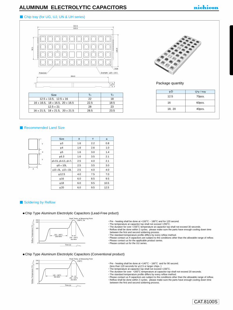
Package quantity
φD Q'ty / tray
12.5 70pcs.
16 60pcs.
18, 20 40pcs.
Chip tray (for UG, UJ, UN & UH series)
ALUMINUM ELECTROLYTIC CAPACITORS
Soldering by Reflow
Recommended Land Size
Ref
low
Tem
pera
ture
(˚C
)
140 ~ 160˚C90s MAX
230
200
150
0
200 ~ 230˚C20s MAX
Time (s)
Peak Temp. at Measuring Point+230˚C
Ref
low
Tem
pera
ture
(˚C
)
150 ~ 180˚C120s MAX
250230
165
0
230 ~ 250˚C30s MAX
Time (s)
Peak Temp. at Measuring Point+250˚C, 5s
Y
Y
a
X
Chip Type Aluminum Electrolytic Capacitors (Lead-Free prduct)
Chip Type Aluminum Electrolytic Capacitors (Conventional product)
Size T1 T2
12.5 × 13.5, 12.5 × 16 22 1816 × 16.5, 18 × 16.5, 20 × 16.5 22.5 18.5
12.5 × 21 28 2316 × 21.5, 18 × 21.5, 20 × 21.5 28.5 23.5
• Pre - heating shall be done at +140˚C ~ 160˚C and for 90 second.(less than 120 seconds for φ12.5 or larger chips. )
• The temperature at capacitor top shall not exceed +230˚C.• The duration for over +200˚C temperature at capacitor top shall not exceed 20 seconds.• The standard temperature profile differs by every reflow method.• Please contact us if capacitors are subject to the conditions other than the allowable range of reflow.• Reflow shall be done within 2 cycles. please make sure the parts have enough cooling down time
between the first and second soldering process.
• Pre - heating shall be done at +150˚C ~ 180˚C and for 120 second.• The temperature at capacitor top shall not exceed +250˚C.• The duration for over +230˚C temperature at capacitor top shall not exceed 30 seconds.• Reflow shall be done within 2 cycles. please make sure the parts have enough cooling down time
between the first and second soldering process.• The standard temperature profile differs by every reflow method.• Please contact us if capacitors are subject to the conditions other than the allowable range of reflow.• Please contact us for the applicable product series.• Please contact us for the UU series.

CAT.8100S
φ4 × 3.0 L 12.0 8.0 5.5 5.0 5.0 3.2φ5 × 3.0 L 12.0 12.0 5.5 6.0 6.0 3.2 — 1 ZDφ6.3 × 3.0 L 16.0 12.0 7.5 7.0 7.0 3.2φ4 × 3.9 L 12.0 8.0 5.5 5.0 5.0 4.3φ5 × 3.9 L 12.0 12.0 5.5 6.0 6.0 4.3 — 1 ZR, ZE, ZGφ6.3 × 3.9 L 16.0 12.0 7.5 7.0 7.0 4.4φ4 × 4.5 L 12.0 8.0 5.5 5.0 5.0 4.9φ5 × 4.5 L 12.0 12.0 5.5 6.0 6.0 4.9 — 1 ZS, ZP, ZTφ6.3 × 4.5 L 16.0 12.0 7.5 7.0 7.0 5.0φ3 × 5.4 L 12.0 8.0 5.5 3.5 3.6 5.8φ4 × 5.4 L 12.0 8.0 5.5 5.0 5.0 5.8φ5 × 5.4 L 12.0 12.0 5.5 6.0 6.0 5.8 — 1 WX, WP, WT, WF, WGφ6.3 × 5.4 L 16.0 12.0 7.5 7.0 7.0 5.8φ8 × 5.4 L 16.0 12.0 7.5 8.7 8.7 5.8φ4 × 5.8 L 12.0 8.0 5.5 5.0 5.0 6.3φ5 × 5.8 L 12.0 12.0 5.5 6.0 6.0 6.3 — 1 WT,UT,UP,UV,UD,UR,UK,UAφ6.3 × 5.8 L 16.0 12.0 7.5 7.0 7.0 6.3φ6.3 × 6.2 L 16.0 12.0 7.5 7.0 7.0 6.3φ8 × 6.2 L 16.0 12.0 7.5 8.7 8.7 6.8φ6.3 × 7.7 L 16.0 12.0 7.5 7.0 7.0 8.0 — 1 WT, WF, UR, UX, UD, UB, WG, UAφ8 × 10 L 24.0 16.0 11.5 8.7 8.7 11.0φ10 × 10 L 24.0 16.0 11.5 10.7 10.7 11.0φ4 × 6.8 L 12.0 8.0 5.5 5.0 5.0 7.3φ5 × 6.8 L 12.0 12.0 5.5 6.0 6.0 7.3φ6.3 × 6.8 L 16.0 12.0 7.5 7.0 7.0 7.3 — 1 UU
φ8 × 12 L 24.0 16.0 11.5 8.7 8.7 13.0φ12.5 × 13.5 L 32.0 24.0 14.2 14.0 14.0 14.0 28.4φ12.5 × 16 L 32.0 24.0 14.2 14.0 14.0 16.3 28.4φ12.5 × 21 L 32.0 24.0 14.2 14.0 14.0 21.3 28.4φ16 × 16.5 L 44.0 28.0 20.2 17.5 17.5 16.8 40.4φ16 × 21.5 L 44.0 28.0 20.2 17.5 17.5 21.8 40.4 2 UG, UJ, UN, UHφ18 × 16.5 L 44.0 32.0 20.2 19.5 19.5 16.8 40.4φ18 × 21.5 L 44.0 32.0 20.2 19.5 19.5 21.8 40.4φ20 × 16.5 L 44.0 36.0 20.2 21.5 21.5 17.0 40.4φ20 × 21.5 L 44.0 36.0 20.2 21.5 21.5 22.0 40.4
ALUMINUM ELECTROLYTIC CAPACITORSTaping Specifications for Chip Type Capacitors
Carrier tape
Reel
φD
A
B
3, 4
14
382
8 ×10, 10 ×8, 10 ×10
26
382
12.5
34
332
16, 18, 20
46
332
8×5.4, 8×6.2, 8×7
18
382
6.3
18
382
5
14
382
φD Q'ty / reel
3, 4 2000pcs.
5, 6.3 1000pcs.
6.3 × 7.7 900pcs.
8 × 5.4, 8 × 6.2, 8 × 7 1000pcs.
8 × 10, 10 × 8, 10 × 10 500pcs.
12.5 × 13.5 200pcs.
12.5 × 16 150pcs.
12.5 × 21, 16 × 16.5, 18 × 16.5 125pcs.
20 × 16.5 100pcs.
16 × 21.5, 18 × 21.5 75pcs.
20 × 21.5 50pcs.
4.0±0.1 2.0±0.1 φ1.5 +0.1–0
P±0.1
A0±0.2
0.4
T2±0.2
1.75
±0.
1F
±0.
1
W±
0.3
B0±
0.2
Unreel direction
Polarized (without for ZE, ZP, WP, UP series)
Package quantity
23
13±0.5
φ50
MIN
φB M
AX
Chip Aluminum Capacitors
A 3
Space to show remains
For φ3 ~ φ10
For φ12.5 ~ φ20
Fig.1
Fig.2φ1.5
A0±0.2P±0.1
4.0±0.12.0±0.1
B0±
0.2
T2±0.2R0.75
F±
0.1
1.75
±0.
1
W±
0.3
G
0.2
0.5
Unreel direction
+0.1–0
Polarized (without for UN series)
Size ItemW P F A0 B0 T2 G
fig. Series

CAT.8100S
T1
T2
304.0
Polarized
315.0
92.1
135.
9
322.6
Example : φ20 × 16.5
Hole
Size
φ3
φ4
φ5
φ6.3
φ8×5.5L, φ8×6.2L, φ8×7L
φ8 × 10L
φ10 × 8L, φ10 × 10L
φ12.5
φ16
φ18
φ20
X
1.6
1.6
1.6
1.6
2.5
2.5
2.5
4.0
6.0
6.0
6.0
Y
2.2
2.6
3.0
3.5
4.0
3.5
4.0
7.5
8.5
9.5
9.5
a
0.8
1.0
1.4
2.1
2.1
3.0
4.0
7.0
9.5
10.5
12.5
Package quantity
φD Q'ty / tray
12.5 70pcs.
16 60pcs.
18, 20 40pcs.
Chip tray (for UG, UJ, UN & UH series)
ALUMINUM ELECTROLYTIC CAPACITORS
Soldering by Reflow
Recommended Land Size
Ref
low
Tem
pera
ture
(˚C
)
140 ~ 160˚C90s MAX
230
200
150
0
200 ~ 230˚C20s MAX
Time (s)
Peak Temp. at Measuring Point+230˚C
Ref
low
Tem
pera
ture
(˚C
)
150 ~ 180˚C120s MAX
250230
165
0
230 ~ 250˚C30s MAX
Time (s)
Peak Temp. at Measuring Point+250˚C, 5s
Y
Y
a
X
Chip Type Aluminum Electrolytic Capacitors (Lead-Free prduct)
Chip Type Aluminum Electrolytic Capacitors (Conventional product)
Size T1 T2
12.5 × 13.5, 12.5 × 16 22 1816 × 16.5, 18 × 16.5, 20 × 16.5 22.5 18.5
12.5 × 21 28 2316 × 21.5, 18 × 21.5, 20 × 21.5 28.5 23.5
• Pre - heating shall be done at +140˚C ~ 160˚C and for 90 second.(less than 120 seconds for φ12.5 or larger chips. )
• The temperature at capacitor top shall not exceed +230˚C.• The duration for over +200˚C temperature at capacitor top shall not exceed 20 seconds.• The standard temperature profile differs by every reflow method.• Please contact us if capacitors are subject to the conditions other than the allowable range of reflow.• Reflow shall be done within 2 cycles. please make sure the parts have enough cooling down time
between the first and second soldering process.
• Pre - heating shall be done at +150˚C ~ 180˚C and for 120 second.• The temperature at capacitor top shall not exceed +250˚C.• The duration for over +230˚C temperature at capacitor top shall not exceed 30 seconds.• Reflow shall be done within 2 cycles. please make sure the parts have enough cooling down time
between the first and second soldering process.• The standard temperature profile differs by every reflow method.• Please contact us if capacitors are subject to the conditions other than the allowable range of reflow.• Please contact us for the applicable product series.• Please contact us for the UU series.

CAT.8100S
φ4 × 3.0 L 12.0 8.0 5.5 5.0 5.0 3.2φ5 × 3.0 L 12.0 12.0 5.5 6.0 6.0 3.2 — 1 ZDφ6.3 × 3.0 L 16.0 12.0 7.5 7.0 7.0 3.2φ4 × 3.9 L 12.0 8.0 5.5 5.0 5.0 4.3φ5 × 3.9 L 12.0 12.0 5.5 6.0 6.0 4.3 — 1 ZR, ZE, ZGφ6.3 × 3.9 L 16.0 12.0 7.5 7.0 7.0 4.4φ4 × 4.5 L 12.0 8.0 5.5 5.0 5.0 4.9φ5 × 4.5 L 12.0 12.0 5.5 6.0 6.0 4.9 — 1 ZS, ZP, ZTφ6.3 × 4.5 L 16.0 12.0 7.5 7.0 7.0 5.0φ3 × 5.4 L 12.0 8.0 5.5 3.5 3.6 5.8φ4 × 5.4 L 12.0 8.0 5.5 5.0 5.0 5.8φ5 × 5.4 L 12.0 12.0 5.5 6.0 6.0 5.8 — 1 WX, WP, WT, WF, WGφ6.3 × 5.4 L 16.0 12.0 7.5 7.0 7.0 5.8φ8 × 5.4 L 16.0 12.0 7.5 8.7 8.7 5.8φ4 × 5.8 L 12.0 8.0 5.5 5.0 5.0 6.3φ5 × 5.8 L 12.0 12.0 5.5 6.0 6.0 6.3 — 1 WT,UT,UP,UV,UD,UR,UK,UAφ6.3 × 5.8 L 16.0 12.0 7.5 7.0 7.0 6.3φ6.3 × 6.2 L 16.0 12.0 7.5 7.0 7.0 6.3φ8 × 6.2 L 16.0 12.0 7.5 8.7 8.7 6.8φ6.3 × 7.7 L 16.0 12.0 7.5 7.0 7.0 8.0 — 1 WT, WF, UR, UX, UD, UB, WG, UAφ8 × 10 L 24.0 16.0 11.5 8.7 8.7 11.0φ10 × 10 L 24.0 16.0 11.5 10.7 10.7 11.0φ4 × 6.8 L 12.0 8.0 5.5 5.0 5.0 7.3φ5 × 6.8 L 12.0 12.0 5.5 6.0 6.0 7.3φ6.3 × 6.8 L 16.0 12.0 7.5 7.0 7.0 7.3 — 1 UU
φ8 × 12 L 24.0 16.0 11.5 8.7 8.7 13.0φ12.5 × 13.5 L 32.0 24.0 14.2 14.0 14.0 14.0 28.4φ12.5 × 16 L 32.0 24.0 14.2 14.0 14.0 16.3 28.4φ12.5 × 21 L 32.0 24.0 14.2 14.0 14.0 21.3 28.4φ16 × 16.5 L 44.0 28.0 20.2 17.5 17.5 16.8 40.4φ16 × 21.5 L 44.0 28.0 20.2 17.5 17.5 21.8 40.4 2 UG, UJ, UN, UHφ18 × 16.5 L 44.0 32.0 20.2 19.5 19.5 16.8 40.4φ18 × 21.5 L 44.0 32.0 20.2 19.5 19.5 21.8 40.4φ20 × 16.5 L 44.0 36.0 20.2 21.5 21.5 17.0 40.4φ20 × 21.5 L 44.0 36.0 20.2 21.5 21.5 22.0 40.4
ALUMINUM ELECTROLYTIC CAPACITORSTaping Specifications for Chip Type Capacitors
Carrier tape
Reel
φD
A
B
3, 4
14
382
8 ×10, 10 ×8, 10 ×10
26
382
12.5
34
332
16, 18, 20
46
332
8×5.4, 8×6.2, 8×7
18
382
6.3
18
382
5
14
382
φD Q'ty / reel
3, 4 2000pcs.
5, 6.3 1000pcs.
6.3 × 7.7 900pcs.
8 × 5.4, 8 × 6.2, 8 × 7 1000pcs.
8 × 10, 10 × 8, 10 × 10 500pcs.
12.5 × 13.5 200pcs.
12.5 × 16 150pcs.
12.5 × 21, 16 × 16.5, 18 × 16.5 125pcs.
20 × 16.5 100pcs.
16 × 21.5, 18 × 21.5 75pcs.
20 × 21.5 50pcs.
4.0±0.1 2.0±0.1 φ1.5 +0.1–0
P±0.1
A0±0.2
0.4
T2±0.2
1.75
±0.
1F
±0.
1
W±
0.3
B0±
0.2
Unreel direction
Polarized (without for ZE, ZP, WP, UP series)
Package quantity
23
13±0.5
φ50
MIN
φB M
AX
Chip Aluminum Capacitors
A 3
Space to show remains
For φ3 ~ φ10
For φ12.5 ~ φ20
Fig.1
Fig.2φ1.5
A0±0.2P±0.1
4.0±0.12.0±0.1
B0±
0.2
T2±0.2R0.75
F±
0.1
1.75
±0.
1
W±
0.3
G
0.2
0.5
Unreel direction
+0.1–0
Polarized (without for UN series)
Size ItemW P F A0 B0 T2 G
fig. Series
CAT.8100S
T1
T2
304.0
Polarized
315.0
92.1
135.
9
322.6
Example : φ20 × 16.5
Hole
Size
φ3
φ4
φ5
φ6.3
φ8×5.5L, φ8×6.2L, φ8×7L
φ8 × 10L
φ10 × 8L, φ10 × 10L
φ12.5
φ16
φ18
φ20
X
1.6
1.6
1.6
1.6
2.5
2.5
2.5
4.0
6.0
6.0
6.0
Y
2.2
2.6
3.0
3.5
4.0
3.5
4.0
7.5
8.5
9.5
9.5
a
0.8
1.0
1.4
2.1
2.1
3.0
4.0
7.0
9.5
10.5
12.5
Package quantity
φD Q'ty / tray
12.5 70pcs.
16 60pcs.
18, 20 40pcs.
Chip tray (for UG, UJ, UN & UH series)
ALUMINUM ELECTROLYTIC CAPACITORS
Soldering by Reflow
Recommended Land Size
Ref
low
Tem
pera
ture
(˚C
)
140 ~ 160˚C90s MAX
230
200
150
0
200 ~ 230˚C20s MAX
Time (s)
Peak Temp. at Measuring Point+230˚C
Ref
low
Tem
pera
ture
(˚C
)
150 ~ 180˚C120s MAX
250230
165
0
230 ~ 250˚C30s MAX
Time (s)
Peak Temp. at Measuring Point+250˚C, 5s
Y
Y
a
X
Chip Type Aluminum Electrolytic Capacitors (Lead-Free prduct)
Chip Type Aluminum Electrolytic Capacitors (Conventional product)
Size T1 T2
12.5 × 13.5, 12.5 × 16 22 1816 × 16.5, 18 × 16.5, 20 × 16.5 22.5 18.5
12.5 × 21 28 2316 × 21.5, 18 × 21.5, 20 × 21.5 28.5 23.5
• Pre - heating shall be done at +140˚C ~ 160˚C and for 90 second.(less than 120 seconds for φ12.5 or larger chips. )
• The temperature at capacitor top shall not exceed +230˚C.• The duration for over +200˚C temperature at capacitor top shall not exceed 20 seconds.• The standard temperature profile differs by every reflow method.• Please contact us if capacitors are subject to the conditions other than the allowable range of reflow.• Reflow shall be done within 2 cycles. please make sure the parts have enough cooling down time
between the first and second soldering process.
• Pre - heating shall be done at +150˚C ~ 180˚C and for 120 second.• The temperature at capacitor top shall not exceed +250˚C.• The duration for over +230˚C temperature at capacitor top shall not exceed 30 seconds.• Reflow shall be done within 2 cycles. please make sure the parts have enough cooling down time
between the first and second soldering process.• The standard temperature profile differs by every reflow method.• Please contact us if capacitors are subject to the conditions other than the allowable range of reflow.• Please contact us for the applicable product series.• Please contact us for the UU series.
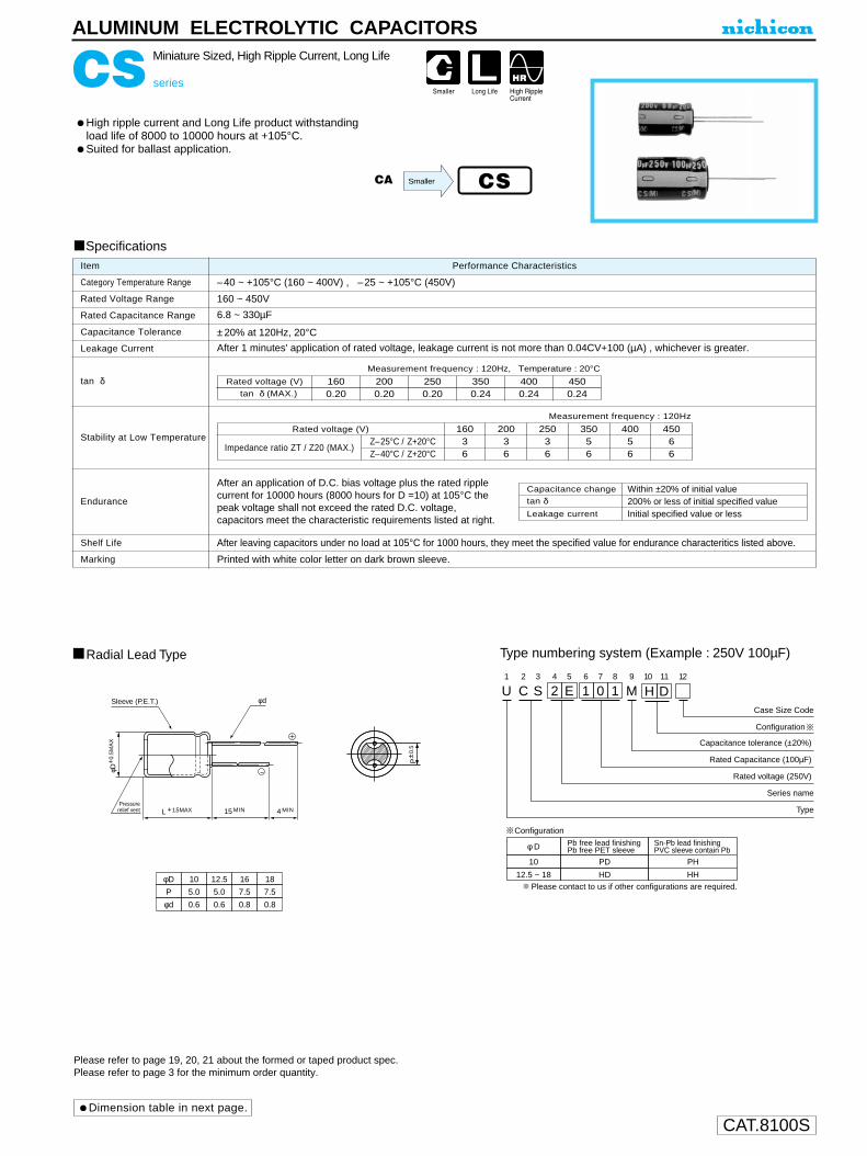
CAT.8100S
CS series
Miniature Sized, High Ripple Current, Long Life
High ripple current and Long Life product withstandingload life of 8000 to 10000 hours at +105°C.Suited for ballast application.
ALUMINUM ELECTROLYTIC CAPACITORS
U1
C2
S3
24
E5
16
07
18
M9 10 11
Capacitance tolerance (±20%)
Rated Capacitance (100µF)
Rated voltage (250V)
H D12
TCase Size Code
Series name
Type
φD
P
10
5.0
12.5
5.0
16
7.5
18
7.5
φd 0.6 0.6 0.8 0.8
L + 1.5MAX 15 MIN 4 MIN
Radial Lead Type
Sleeve (P.E.T.) φd
Pressurerelief vent
Type numbering system (Example : 250V 100µF)
Configuration
φD+
0.5M
AX
P±0
.5
φ D
10
Pb free lead finishingPb free PET sleeve
PD
12.5 ~ 18 HD
Configuration
Sn-Pb lead finishingPVC sleeve contain Pb
PH
HH Please contact to us if other configurations are required.
Dimension table in next page.
Please refer to page 19, 20, 21 about the formed or taped product spec.Please refer to page 3 for the minimum order quantity.
Specifications
Category Temperature Range
Rated Voltage Range
Rated Capacitance Range
Capacitance Tolerance
Leakage Current
tan δ
Stability at Low Temperature
Endurance
Shelf Life
Marking
Performance CharacteristicsItem
–40 ~ +105°C (160 ~ 400V) , –25 ~ +105°C (450V)
160 ~ 450V
6.8 ~ 330µF
±20% at 120Hz, 20°C
After 1 minutes' application of rated voltage, leakage current is not more than 0.04CV+100 (µA) , whichever is greater.
Printed with white color letter on dark brown sleeve.
After leaving capacitors under no load at 105°C for 1000 hours, they meet the specified value for endurance characteritics listed above.
Measurement frequency : 120Hz
Capacitance change
Leakage current
After an application of D.C. bias voltage plus the rated ripplecurrent for 10000 hours (8000 hours for D =10) at 105°C thepeak voltage shall not exceed the rated D.C. voltage,capacitors meet the characteristic requirements listed at right.
tan δWithin ±20% of initial value
Initial specified value or less200% or less of initial specified value
Z–25°C / Z+20°CZ–40°C / Z+20°C
Rated voltage (V)
Impedance ratio ZT / Z20 (MAX.)
16036
20036
25036
35056
40056
45066
Measurement frequency : 120Hz, Temperature : 20°C
Rated voltage (V)tan δ (MAX.)
1600.20
2000.20
2500.20
4000.24
4500.24
3500.24
CSCA Smaller

CAT.8100S
CS series
ALUMINUM ELECTROLYTIC CAPACITORS
V
10 × 16
10 × 20
10 × 20
10 × 20
12.5 × 25
12.5 × 20
12.5 × 25
16 × 20
16 × 20
16 × 25
18 × 31.5
315
500
625
750
1175
1275
1395
1420
1735
2295
3130
10 × 16
10 × 20
10× 20
12.5 × 20
12.5 × 20
16 × 20
16 × 20
16 × 25
18 × 25
18 × 35.5
315
500
650
975
1175
1375
1420
1890
2365
3220
10 × 20
10 × 20
12.5 × 20
12.5 × 20
16 × 20
16 × 20
16 × 25
18 × 25
18 × 31.5
350
500
800
975
1300
1375
1530
1935
3130
10 × 16
10 × 20
12.5 × 20
16 × 20
16 × 20
16 × 25
18 × 20
18 × 25
18 × 25
275
350
650
900
1075
1400
1375
1525
1575
10 × 16
10 × 20
12.5 × 20
12.5 × 20
16 × 20
16 × 25
18 × 20
18 × 25
18 × 25
275
350
550
650
900
1175
1125
1465
1525
10 × 20
12.5 × 20
12.5 × 25
16 × 20
16 × 25
18 × 20
18 × 25
18 × 31.5
275
450
600
725
975
950
1200
1575
2C 2D 2E 2V 2G 2W
160 200 250 350 400 450
Case size
: Rated Ripple (Arms) at 105°C 100kHz
: In this case, 6 will be put at 12th digit of type numbering system.
Frequency
Coefficient
120Hz
0.50
1kHz
0.80
10kHz
0.90
100kHz ~
1.00
D × L (mm)Dimensions
Frequency coefficient of rated ripple current
Cap Code
6.8
10
15
22
33
47
68
82
100
150
220
330
6R8
100
150
220
330
470
680
820
101
151
221
331
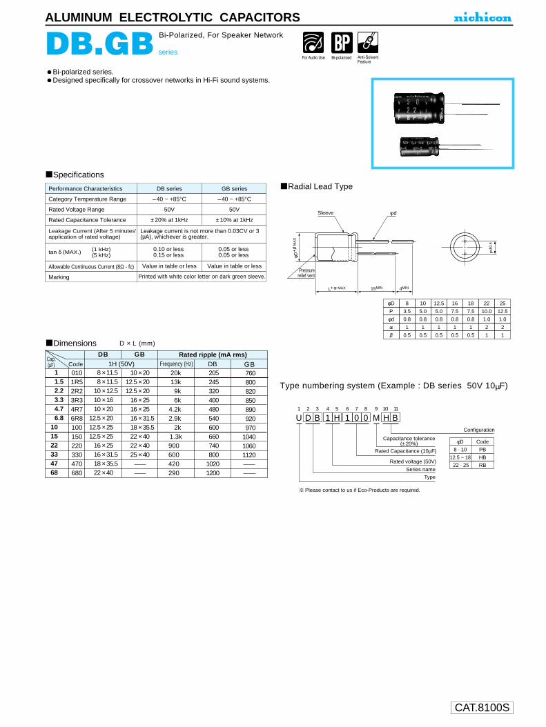
CAT.8100S
Bi-polarized series.Designed specifically for crossover networks in Hi-Fi sound systems.
ALUMINUM ELECTROLYTIC CAPACITORS
DB.GB series
Bi-Polarized, For Speaker Network
Performance Characteristics
Category Temperature Range
Rated Voltage Range
Rated Capacitance Tolerance
Leakage Current (After 5 minutes'application of rated voltage)
tan δ (MAX.) (1 kHz)(5 kHz)
Allowable Continuous Current (8Ω - fc)
Marking
–40 ~ +85°C –40 ~ +85°C
50V 50V
±20% at 1kHz ±10% at 1kHz
Leakage current is not more than 0.03CV or 3(µA), whichever is greater.
0.10 or less0.15 or less
0.05 or less0.05 or less
Value in table or less Value in table or less
Printed with white color letter on dark green sleeve.
DB series GB series
SpecificationsRadial Lead Type
Type numbering system (Example : DB series 50V 10µF)
L+ MAX 15MIN 4MIN
Sleeve φ d
φD+
M
AX
P±0
.5
φD
P
φd
8
3.5
0.8
10
5.0
0.8
12.5
5.0
0.8
16
7.5
0.8
18
7.5
0.8
1 1 1 1 1
0.5 0.5 0.5 0.5 0.5
22
10.0
1.0
2
1
25
12.5
1.0
2
1
Pressurerelief vent
U1
D2
B3
14
H5
16
07
08
M9
H10
B11
Configuration
Capacitance tolerance (± 20%)
Rated Capacitance (10µF)
Rated voltage (50V)
Series name
Type
φD
8 · 10
Code
PB
12.5 ~ 18 HB
22 · 25 RB
Please contact to us if Eco-Products are required.
Dimensions
11.52.23.34.76.8
101522334768
0101R52R23R34R76R8100150220330470680
8 × 11.58 × 11.5
10 × 12.510 × 1610 × 20
12.5 × 2012.5 × 2512.5 × 25
16 × 2516 × 31.518 × 35.522 × 40
10 × 2012.5 × 2012.5 × 20
16 × 2516 × 2516 × 31.518 × 35.522 × 4022 × 4025 × 40
20k13k
9k6k
4.2k2.9k
2k1.3k900600420290
205245320400480540600660740800
10201200
760800820850890920970
104010601120
1H (50V)Cap. .(µF)
DB GBFrequency (Hz)
Rated ripple (mA rms)DBCode GB
D × L (mm)

CAT.8100S
D2
L1
M3
24
D5
46
77
18
M9
E10
R11
Z12
G13
A14
Case dia. code
Configuration
Capacitance tolerance (±20%)
Rated Capacitance (470µF)
Rated voltage (200V)
Series name
Type
φD
20
22
Code
Y
Z
25 A
Lead wire configuration GA: Left side from the front HA: Right side from the front ( )
2.0Pressure relief vent
L±2
±1
0.6
3.5±1
8.0±2
φD+1
MA
X.
P
φ20 : P=7.5φ22, φ25 : P=8.5
Sleeve (P.E.T.)
Pb free lead finishingPb free PET sleeve
Sn-Pb lead finishingPVC sleeve contain Pb
ER LR
Configuration
Please contact to us if other configurations are required.
ALUMINUM ELECTROLYTIC CAPACITORS
DM series
Horizontal Mounting Type
For φ20, φ22 and φ25, but suited for horizontal mountingtoassure flat and low-profile design.
Drawing Type numbering system (Example : 200V 470µF)
DM
DQ
Specifications
Category Temperature RangeRated Voltage RangeRated Capacitance RangeCapacitance ToleranceLeakage Current
tan δ
Stability at Low Temperature
Endurance
Shelf Life
Marking
Performance CharacteristicsItem
– 40 ~ + 85°C (200V), – 25 ~ + 85°C (400V)200 • 400V82 ~ 1200µF±20% at 120Hz, 20°CI (µA) (After 5 minutes' application of rated voltage) [C : Rated Capacitance (µF), V : Voltage(V)]
Printed with white color letter on black sleeve.
Measurement frequency : 120Hz, Temperature : 20°C
Capacitance change
Leakage current
After an application of DC voltage (in the range of ratedDC voltage even after over-lapping the specified ripplecurrent) for 2000 hours at 85°C, capacitors meet thecharacteristic requirements listed at right.
After leaving capacitors under no load at 85°C
for 1000 hours, they meet the characteristic
requirements at right.
tan δWithin ±20% of initial value
Initial specified value or less
200% or less of initial specified value
Rated voltage (V)tan δ (MAX.)
4000.15
2000.15
Measurement frequency : 120Hz
Z—25°C/Z+20°C
Z—40°C/Z+20°C
Rated voltage (V)
Impedance ratioZT/Z20(MAX.)
200312
4008—
Capacitance change
Leakage current
tan δWithin ±15% of initial value
Initial specified value or less
150% or less of initial specified value
Dimensions
Rated Ripple (A rms) at 85°C 120HzOther ratings also available on request.
Frequency coefficient of rated ripple currentFrequency (Hz)
200V400V
Coeff.
50 60 120 300 1k 10k 50k~0.81 0.85 1.00 1.17 1.32 1.45 1.500.77 0.82 1.00 1.16 1.30 1.41 1.43
008201000120015001800220027003300390047005600680082010001200
820101121151181221271331391471561681821102122
20 × 3020 × 3020 × 3520 × 4020 × 4520 × 50
1.321.491.661.932.002.30
22 × 3522 × 4022 × 4522 × 5022 × 60
1.881.962.432.803.00
25 × 3525 × 4025 × 4525 × 60
2.682.803.123.44
20 × 3020 × 3020 × 3520 × 4020 × 50
0.780.901.021.171.30
22 × 3522 × 4022 × 4522 × 60
1.201.381.551.70
25 × 3525 × 4025 × 4525 × 5025 × 60
Case size
1.251.561.701.902.15
400V (2G)
20 22 25 20 22 25
D × L (mm)
200V (2D)
Ratedripple
V(Code)
φDCodeCap.(µF)
HighTemperature
3 CV
Minimum order quantity : 50pcs.

CAT.8100SMinimum order quantity : 50pcs.
Item Performance Characteristics
DM
ALUMINUM ELECTROLYTIC CAPACITORS
DQ series
Horizontal Mounting Type, Wide Temperature Range
Horizontal mounting version for φ20 ,φ22 and φ25.Suited for use in flat electronic devices where height space is limited. DQ
Specifications
Category Temperature RangeRated Voltage RangeRated Capacitance RangeCapacitance ToleranceLeakage Current
tan δ
Stability at Low Temperature
Endurance
Shelf Life
Marking
– 40 ~ +105°C (200V) , – 25~+105°C (400V) 200 • 400V68 ~ 1200µF±20% at 120Hz, 20°CI (µA) (After 5 minutes' application of rated voltage) [C : Rated Capacitance (µF) V : Voltage(V)]
Capacitance change
tan δLeakage current
Within ±20% of initial value
200% or less of initial specified value
Initial specified value or less
Capacitance change
tan δLeakage current
Within ±15% of initial value
150% or less of initial specified value
Initial specified value or less
After an application of DC voltage(in the range of rated DCvoltage even after over-lapping the specified ripple current)for 2000 hours at 105°C, capacitors meet the characteristicrequirements listed at right.
Printed with white color letter on black sleeve.
Frequency coefficient of rated ripple current
Other rating also available on request. Rated Ripple (A rms) at 105°C, 120Hz
2.0
L±2
±1
0.6
3.5±1
φD+1
MA
X.
P
D2
L1
Q3
24
D5
46
77
18
M9
E10
R11
Z12
G13
A14
φD
20
22
Y
Z
25 A
φ20 : P=7.5φ22, φ25 : P=8.5
Sleeve (P.E.T.)
Pressure relief vent
Case dia.code
Configuration
HA : Right side from the front
GA : Left side from the front Lead wire configurationt
Capacitance tolerance(±20%)
Rated Capacitance(470µF)
Rated voltage(200V)
Series name
Type
Code
( )
8.0±2
Pb free lead finishingPb free PET sleeve
Sn-Pb lead finishingPVC sleeve contain Pb
ER LR
Configuration
Please contact to us if other configurations are required.
Drawing Type numbering system (Example : 200V 470µF)
After leaving capacitors under no load at 105°C for 1000hours, they meet the requirements listed at right.
Coeff.
Frequency (Hz)
Dimensions D×L (mm)
200V400V
500.810.77
600.850.82
1201.001.00
3001.171.16
1k1.321.30
10k1.451.41
50k~1.501.43
6882
100120150180220270330390470560680820
10001200
680820101121151181221271331391471561681821102122
20 × 3020 × 3520 × 4020 × 4520 × 50
1.101.201.311.451.58
22 × 3522 × 4022 × 4522 × 60
1.451.601.782.04
25 × 3525 × 4025 × 4525 × 5025 × 60
1.601.782.042.302.65
20 × 3020 × 3020 × 3520 × 4020 × 4520 × 50
0.560.640.700.750.830.95
22 × 3522 × 4022 × 4522 × 5022 × 60
0.750.880.951.101.22
25 × 3525 × 4025 × 4525 × 50
Case size
0.951.101.221.44
Rated
200V (2D) 20 22 25 20 22 25
400V (2G) V(Code)
φDCodeCap.(µF)
Rated voltage (V)tan δ (MAX.)
2000.15
4000.15
Measurement frequency : 120Hz, Temperature : 20°C
200312
4008—
Measurement frequency : 120Hz
Z—25°C/Z+20°C
Z—40°C/Z+20°C
Rated voltage (V)
Impedance ratioZT/Z20(MAX.)
HighTemperature
3 CV

CAT.8100S
PLASTIC FILM CAPACITORS
EH series
Metallized Polypropylene Film AC Power Capacitor
Specifications
DrawingPlease refer to page 249.
Item Performance Characteristics
Maximum permissibletemperature +85˚C (Z)
Minimum ambienttemperature – 25˚C (B)
Rated Voltage Range 200 ~ 460VACRated Capacitance Range 1.0 ~ 30µFCapacitance Tolerance +10 ~ –5%Dielectric Loss Tangent 0.12% or less (at 20˚C, 50 / 60Hz 200VAC)
Withstand VoltageBetween Terminals : Rated Voltage (VAC) × 175% 10secs.Between Terminals connected together and case : 2000VAC 60secs.
Insulation ResistanceBetween Terminals connected together and case :
1000 MΩ or more (at 500VDC)
Encapsulation Flame-retardant epoxy cased, Resin filledCurrent duration class 40D (40,000h)Safety Mechanism Non-included
Dimensions Unit : mm
1.01.52.02.53.03.54.04.55.06.07.08.0
10.012.014.015.016.018.020.022.025.030.0
105155205255305355405455505605705805106126146156166186206226256306
A––
37.037.037.037.037.037.037.037.037.037.037.037.037.037.037.048.048.058.058.058.0
B––
11.511.511.511.511.513.513.513.515.515.517.521.524.024.024.021.524.026.026.026.0
C––
25.025.025.025.025.027.027.027.029.029.031.035.037.037.037.035.038.040.040.040.0
Fig.
qr
u
wt
ey
200VAC (2D)(µF)Cap.
CodeSize
V (Code)
A––
37.037.037.037.037.037.037.037.037.037.037.037.037.037.037.048.048.058.058.058.0
B––
11.511.511.511.511.513.513.513.515.515.517.521.524.024.024.021.524.026.026.026.0
C––
25.025.025.025.025.027.027.027.029.029.031.035.037.037.037.035.038.040.040.040.0
Fig.
qr
u
wt
ey
250VAC (2E) 400VAC (2G) 460VAC (W7)A
37.037.037.037.037.037.037.037.037.037.037.048.058.058.058.058.0
B11.511.513.515.515.517.519.519.521.524.024.024.026.026.030.030.0
C25.025.027.029.029.031.033.033.035.037.037.038.040.040.044.044.0
Fig.
qr
u
w t
e y
A37.037.037.037.037.037.037.037.037.048.058.058.058.058.058.058.0
B11.513.515.517.519.521.521.524.024.024.026.026.030.030.034.034.0
C25.027.029.031.033.035.035.037.037.038.040.040.044.044.049.049.0
Fig.
qr
u
w t
ey

CAT.8100S
20 ± 0.5
G ± 2
A ±1
4.51
12 ±
0.5
10 ±
3C
± 1
3.5
± 0.3
B ± 1
187Tab terminal
Resin case
Resin filled
6 ±
0.5 20 ± 0.5
G ± 2
A ± 1.5
10 ±
0.54.
5 ±
0.5
10 ±
3C
± 1
.5
3.5
± 0.
3
B ±
1
187Tab terminal
Resin case
Resin filled
φ 4.325 ± 0.5
G ± 2
A ± 1.5
12 ±
0.56
± 0.5
10 ±
3C
± 1
.5
4 ±
0.3
B ±
1
187Tab terminal
Resin case
Resin filled
φ 4.5
G ± 2
A ± 1
10 ±
3C
± 1
3.5
± 0.
3
187Tab terminal
Resin case
20 ± 0.54.51
12 ±
0.56
± 0.5
B ±
1
Resin filled
20 ± 0.5
G ± 2
A ± 1.5
10 ±
0.54.
5 ± 0
.5
10 ±
3C
± 1
.5
3.5
± 0.3
B ±
1
187Tab terminal
Resin case
Resin filled
φ 4.325 ± 0.5
G ± 2
A ± 1.5
12 ±
0.56
± 0.
5
10 ±
3C
± 1
.5
4 ±
0.3
B ±
1
187Tab terminal
Resin case
Resin filled
φ 4.5
G ± 1.0
A ± 1 B ± 1
10 ±
2
C ±
1
Resin case
Resin filled
φ 0.8CP wire
Marking Marking Marking
MarkingMarkingMarking
Marking
Dimensions
In case of pin terminal product, dimension will be 37.0 × 13.5 × 28.0mm. (Code : /. )In case of pin terminal product, dimension will be 37.0 × 15.5 × 29.0mm. (Code : xm )In case of pin terminal product, dimension will be 37.0 × 17.5 × 31.0mm. (Code : zz )
Tab terminal 1 (Terminal shape : Ω )
Fig.q Fig.w Fig.e
Fig.r
Fig.u
Fig.t Fig.y
Remarks : 1) Tab terminal product has bracket as standard. It is also available without bracket.
2) Dimension of case bottom is expressed by A and B.
3) Dimension B of case top shall be ±1.0mm as shown below.
4) In case of pin terminal product, cased dimension A is only 37mm.
± 1.0mm of B dimension
Drawing
PLASTIC FILM CAPACITORS
EH,EN series
Tab terminal 2 (Terminal shape : Π)
Pin terminal (Terminal shape : ∑ )
Case size (mm) Case size codeLead pitch G (mm)
( ) for Pin terminalTerminal Shape Q Terminal Shape Z Terminal Shape W
A B C Terminal 2 Fig Terminal 1 Fig Pin terminal Fig37.0 11.5 25.0 /z
37.0 13.5 27.0 /x (/.)37.0 15.5 29.0 /c (xm)37.0 17.5 31.0 /v (zz) 27.0 q 30.0 r 34.2 u
37.0 19.5 33.0 /b
37.0 21.5 35.0 /n
37.0 24.0 37.0 /m
48.0 21.5 35.0 zc37.0 w 40.0 t
48.0 24.0 38.0 zv
58.0 26.0 40.0 zb
58.0 30.0 44.0 zn 47.0 e 50.0 y
58.0 34.0 49.0 cz

CAT.8100S
PLASTIC FILM CAPACITORS
DrawingPlease refer to page 249.
Specifications
Dimensions
Please indicate as "EEN" series when applying to UL.
Item Performance Characteristics
UL Approved No. UL810 FILE No.E86988
Maximum permissible +70˚C (M)temperature
Minimum ambient –25˚C (B)temperature
Rated Voltage Range 200 ~ 440VACRated Capacitance Range 1.0 ~ 30µFCapacitance Tolerance +10 ~ –5%Dielectric Loss Tangent 0.12% or less (at 20˚C, 50/60Hz 200VAC)
Withstand VoltageBetween Terminals : Rated Voltage (VAC) × 175% 10secs.Between Terminals connected together and case : 2000VAC 60secs.
Insulation ResistanceBetween Terminals connected together and case :
1000 MΩ or more (at 500VDC)
Encapsulation Flame-retardant epoxy cased, Resin filledCurrent duration class 40D (40,000h)Safety Mechanism Included
EN series
Metallized Polypropylene Film AC Power CapacitorSafety Mechanism,UL810 approved (Failure current 5,000A)
1.0 1.5 2.0 2.5 3.0 3.5 4.0 4.5 5.0 6.0 7.0 8.0
10.0 12.0 14.0 15.0 16.0 18.0 20.0 22.0 25.0 30.0
105155205255305355405455505605705805106126146156166186206226256306
A37.037.037.037.037.037.037.037.037.037.037.037.037.037.048.048.048.058.058.058.058.058.0
B11.511.511.511.511.513.513.515.515.517.517.519.521.524.021.524.024.026.026.026.026.030.0
C25.025.025.025.025.027.027.029.029.031.031.033.035.037.035.038.038.040.040.040.040.044.0
A37.037.037.037.037.037.037.037.037.037.037.037.037.048.048.058.058.058.058.058.058.0
B11.511.511.511.513.513.515.515.517.519.521.521.524.024.024.026.026.026.026.030.030.0
C25.025.025.025.027.027.029.029.031.033.035.035.037.038.038.040.040.040.040.044.044.0
A37.037.037.037.037.037.048.048.048.058.058.058.058.0
B13.515.517.519.521.524.021.524.024.026.026.026.030.0
C27.029.031.033.035.037.035.038.038.040.040.040.044.0
A37.037.037.037.037.048.048.058.058.058.058.058.0
B13.517.519.524.024.024.024.026.026.026.030.030.0
C27.031.033.037.037.038.038.040.040.040.044.044.0
q r
u
w t
w t
w t
w t
e y
e y
e y
e y
q r
u
q r
u
q r
u
V(Code)SizeCode(µF)
Cap
200VAC (2D)Fig. Fig. Fig. Fig.
250VAC (2E) 400VAC (2G) 440VAC (Y5)
Unit : mm

CAT.8100S
20 ± 0.5
G ± 2
A ±1
4.51
12 ±
0.5
10 ±
3C
± 1
3.5
± 0.3
B ± 1
187Tab terminal
Resin case
Resin filled
6 ±
0.5 20 ± 0.5
G ± 2
A ± 1.5
10 ±
0.54.
5 ±
0.5
10 ±
3C
± 1
.5
3.5
± 0.
3
B ±
1
187Tab terminal
Resin case
Resin filled
φ 4.325 ± 0.5
G ± 2
A ± 1.5
12 ±
0.56
± 0.5
10 ±
3C
± 1
.5
4 ±
0.3
B ±
1
187Tab terminal
Resin case
Resin filled
φ 4.5
G ± 2
A ± 1
10 ±
3C
± 1
3.5
± 0.
3
187Tab terminal
Resin case
20 ± 0.54.51
12 ±
0.56
± 0.5
B ±
1
Resin filled
20 ± 0.5
G ± 2
A ± 1.5
10 ±
0.54.
5 ± 0
.5
10 ±
3C
± 1
.5
3.5
± 0.3
B ±
1
187Tab terminal
Resin case
Resin filled
φ 4.325 ± 0.5
G ± 2
A ± 1.5
12 ±
0.56
± 0.
5
10 ±
3C
± 1
.5
4 ±
0.3
B ±
1
187Tab terminal
Resin case
Resin filled
φ 4.5
G ± 1.0
A ± 1 B ± 1
10 ±
2
C ±
1
Resin case
Resin filled
φ 0.8CP wire
Marking Marking Marking
MarkingMarkingMarking
Marking
Dimensions
In case of pin terminal product, dimension will be 37.0 × 13.5 × 28.0mm. (Code : /. )In case of pin terminal product, dimension will be 37.0 × 15.5 × 29.0mm. (Code : xm )In case of pin terminal product, dimension will be 37.0 × 17.5 × 31.0mm. (Code : zz )
Tab terminal 1 (Terminal shape : Ω )
Fig.q Fig.w Fig.e
Fig.r
Fig.u
Fig.t Fig.y
Remarks : 1) Tab terminal product has bracket as standard. It is also available without bracket.
2) Dimension of case bottom is expressed by A and B.
3) Dimension B of case top shall be ±1.0mm as shown below.
4) In case of pin terminal product, cased dimension A is only 37mm.
± 1.0mm of B dimension
Drawing
PLASTIC FILM CAPACITORS
EH,EN series
Tab terminal 2 (Terminal shape : Π)
Pin terminal (Terminal shape : ∑ )
Case size (mm) Case size codeLead pitch G (mm)
( ) for Pin terminalTerminal Shape Q Terminal Shape Z Terminal Shape W
A B C Terminal 2 Fig Terminal 1 Fig Pin terminal Fig37.0 11.5 25.0 /z
37.0 13.5 27.0 /x (/.)37.0 15.5 29.0 /c (xm)37.0 17.5 31.0 /v (zz) 27.0 q 30.0 r 34.2 u
37.0 19.5 33.0 /b
37.0 21.5 35.0 /n
37.0 24.0 37.0 /m
48.0 21.5 35.0 zc37.0 w 40.0 t
48.0 24.0 38.0 zv
58.0 26.0 40.0 zb
58.0 30.0 44.0 zn 47.0 e 50.0 y
58.0 34.0 49.0 cz
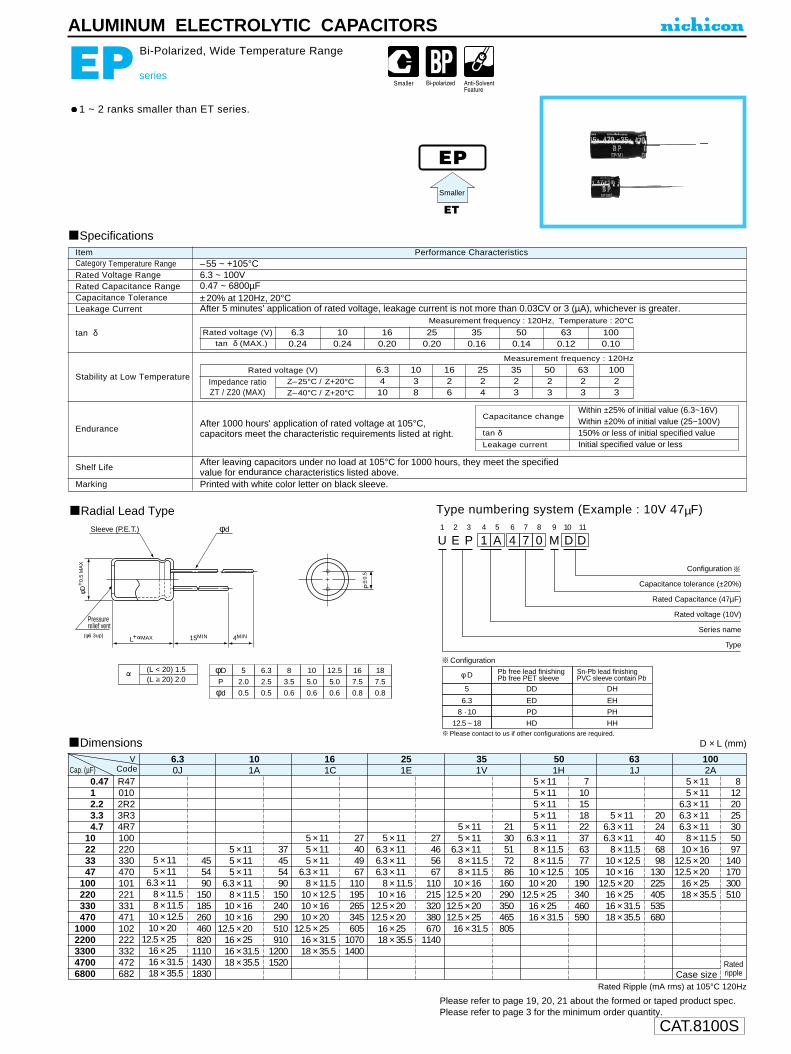
CAT.8100S
U1
E2
P3
14
A5
46
77
08
M9
D10
D11
Configuration
Capacitance tolerance (±20%)
Rated Capacitance (47µF)
Rated voltage (10V)
Series name
Type
Pressurerelief vent
15MIN 4MIN
Sleeve (P.E.T.) φd
P±0
.5
(φ6.3up)
φD
P
φd
5
2.0
0.5
6.3
2.5
0.5
8
3.5
0.6
10
5.0
0.6
12.5
5.0
0.6
16
7.5
0.8
18
7.5
0.8
φD+
0.5
MA
X
L+ MAX
(L < 20) 1.5(L 20) 2.0
φ D
5
Pb free lead finishingPb free PET sleeve
Sn-Pb lead finishingPVC sleeve contain Pb
DD DH
6.3 ED EH
8 · 10 PD PH
12.5 ~ 18 HD HH
Configuration
Please contact to us if other configurations are required.
ALUMINUM ELECTROLYTIC CAPACITORS
EP series
Bi-Polarized, Wide Temperature Range
1 ~ 2 ranks smaller than ET series.
Radial Lead Type Type numbering system (Example : 10V 47µF)
Specifications
Category Temperature RangeRated Voltage RangeRated Capacitance RangeCapacitance ToleranceLeakage Current
tan δ
Stability at Low Temperature
Endurance
Shelf Life
Marking
Performance CharacteristicsItem–55 ~ +105°C6.3 ~ 100V0.47 ~ 6800µF±20% at 120Hz, 20°CAfter 5 minutes' application of rated voltage, leakage current is not more than 0.03CV or 3 (µA), whichever is greater.
Printed with white color letter on black sleeve.
Measurement frequency : 120Hz, Temperature : 20°C
Measurement frequency : 120Hz
After 1000 hours' application of rated voltage at 105°C, capacitors meet the characteristic requirements listed at right.
After leaving capacitors under no load at 105°C for 1000 hours, they meet the specified value for endurance characteristics listed above.
EP
ET
Rated voltage (V)tan δ (MAX.)
6.30.24
100.24
160.20
250.20
350.16
500.14
630.12
1000.10
Z–25°C / Z+20°C
Z–40°C / Z+20°C
Rated voltage (V)
Impedance ratioZT / Z20 (MAX)
6.3410
1038
1626
2524
3523
5023
6323
10023
Smaller
Leakage current
tan δ
Capacitance changeWithin ±25% of initial value (6.3~16V)Within ±20% of initial value (25~100V)150% or less of initial specified valueInitial specified value or less
Please refer to page 19, 20, 21 about the formed or taped product spec.Please refer to page 3 for the minimum order quantity.
5 × 115 × 11
6.3 × 116.3 × 116.3 × 11
8 × 11.510 × 16
12.5 × 2012.5 × 20
16 × 2518 × 35.5
37455490
150240290510910
12001520
5 × 115 × 115 × 115 × 115 × 11
6.3 × 118 × 11.58 × 11.5
10 × 12.510 × 20
12.5 × 2516 × 2516 × 31.5
8122025305097
140170300510
Ratedripple
2024406898
130225405535680
710151822376377
105190340460590
2130517286
160290350465805
27404967
110195265345605
10701400
5 × 115 × 115 × 11
6.3 × 118 × 11.5
10 × 1610 × 16
12.5 × 2016 × 2516 × 31.518 × 35.5
0.4712.23.34.7
10223347
100220330470
10002200330047006800
Dimensions
R470102R23R34R7100220330470101221331471102222332472682
5 × 115 × 11
6.3 × 118 × 11.58 × 11.5
10 × 12.510 × 20
12.5 × 2516 × 2516 × 31.518 × 35.5
455490
150185260460820
111014301830
0J
Rated Ripple (mA rms) at 105°C 120Hz
6.31A10
1C16
1E25
1V35
1H50
1J 2A63 100
5 × 115 × 115 × 11
6.3 × 118 × 11.5
10 × 12.510 × 1610 × 20
12.5 × 2516 × 31.518 × 35.5
5 × 115 × 11
6.3 × 118 × 11.58 × 11.5
10 × 1612.5 × 2012.5 × 2012.5 × 25
16 × 31.5
5 × 116.3 × 116.3 × 11
8 × 11.510 × 12.510 × 16
12.5 × 2016 × 2516 × 31.518 × 35.5
D × L (mm)
5 × 116.3 × 116.3 × 116.3 × 11
8 × 11.510 × 16
12.5 × 2012.5 × 20
16 × 2518 × 35.5
27465667
110215320380670
1140
Case size
VCodeCap. (µF)

CAT.8100S
U1
E2
S3
14
A5
46
77
08
M9
E10
J11
Configuration
Capacitance tolerance (±20%)
Rated Capacitance (47µF)
Rated voltage (10V)
Series name
Type
φD
5
Code
DJ
6.3 EJ
8 · 10 PJ
12.5 · 16 HJ
L+ MAX
Pressurerelief vent
15MIN 4MIN
Sleeve φ d
φD+
0.5
MA
X
P±0
.5
φD
P
φd
5
2.0
0.6
6.3
2.5
0.6
8
3.5
0.6
10
5.0
0.6
12.5
5.0
0.8
16
7.5
0.8 (φ6.3up)
(φD < 10) 1.0 (φD 10) 1.5
Please contact to us if Eco-Products are required.
ALUMINUM ELECTROLYTIC CAPACITORS
ES series
Bi-Polarized, For Audio Equipment
Bi-polarized “nichicon MUSE” acoustic series.Suited for audio signal circuits.
Radial Lead Type Type numbering system (Example : 10V 47µF)
Specifications
Category Temperature Range
Rated Voltage Range
Rated Capacitance Range
Capacitance Tolerance
Leakage Current
tan δ
Stability at Low Temperature
Endurance
Shelf Life
Marking
Performance CharacteristicsItem
–40 ~ +85°C
6.3 ~ 50V
0.47 ~ 1000µF
±20% at 120Hz, 20°C
After 1 minute's application of rated voltage, leakage current is not more than 0.03CV or 3 (µA), whichever is greater.
Printed with black color letter on clear green sleeve.
Measurement frequency : 120Hz, Temperature : 20°C
Measurement frequency : 120Hz
Capacitance change
Leakage current
After 1000 hours' application of rated voltage at 85°C
with the polarity inverted every 250 hours, capacitors
meet the characteristics requirement listed at right.
After leaving capacitors under no load at 85°C for 1000 hours, they meet the specified value for endurance characteristics listed above.
ES
tan δWithin ±20% of initial value150% or less of initial specified value
Initial specified value or less
Rated voltage (V)tan δ (MAX.)
6.30.24
100.20
160.16
250.16
350.14
500.12
Z–25°C / Z+20°C
Z–40°C / Z+20°C
Rated voltage (V)
Impedance ratioZT / Z20 (MAX.)
6.348
1036
1624
2524
3524
5024
FG
Dimensions
0.4712.23.34.7
10223347
100220330470
1000
R470102R23R34R7100220330470101221331471102
5 × 116.3 × 11
8 × 11.510 × 12.510 × 1610 × 20
12.5 × 25
0J
6.3
5 × 116.3 × 116.3 × 1110 × 12.510 × 1610 × 20
12.5 × 2016 × 25
1A
10
5 × 116.3 × 116.3 × 11
8 × 11.510 × 12.510 × 20
12.5 × 2012.5 × 25
16 × 25
1C
16
5 × 115 × 11
6.3 × 118 × 11.5
10 × 12.510 × 16
12.5 × 2512.5 × 25
16 × 2516 × 31.5
1E
25
5 × 116.3 × 11
8 × 11.510 × 12.510 × 12.510 × 20
12.5 × 2516 × 2516 × 25
1V
35
5 × 115 × 115 × 115 × 11
6.3 × 118 × 11.5
10 × 12.510 × 1610 × 20
12.5 × 2516 × 2516 × 31.5
1H
50
D × L (mm)
V
CodeCap.(µF)
Bi-polarized
Please refer to page 19, 20, 21 about the formed or taped product spec.Please refer to page 3 for the minimum order quantity.
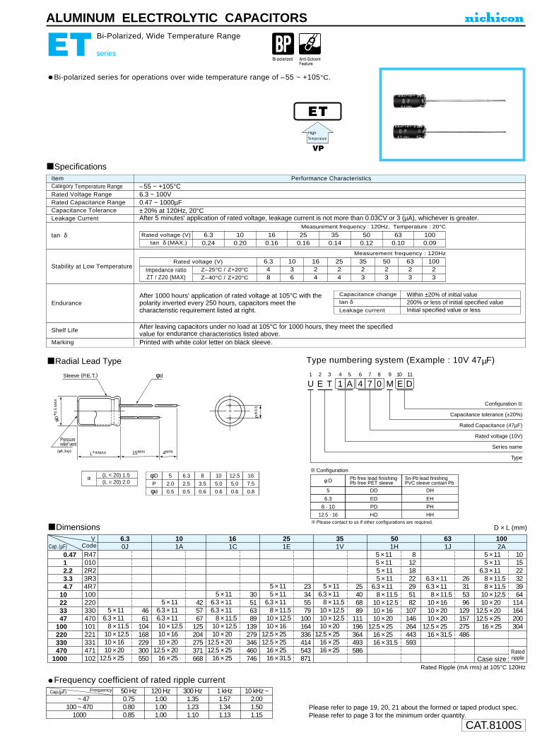
CAT.8100S
U1
E2
T3
14
A5
46
77
08
M9
E10
D11
Configuration
Capacitance tolerance (±20%)
Rated Capacitance (47µF)
Rated voltage (10V)
Series name
Type
Pressurerelief vent
15MIN 4MIN
φd
P±0
.5
(φ6.3up)
φD
P
φd
5
2.0
0.5
6.3
2.5
0.5
8
3.5
0.6
10
5.0
0.6
12.5
5.0
0.6
16
7.5
0.8
φD+
0.5
MA
X
L+ MAX
(L < 20) 1.5(L 20) 2.0 φ D
5
Pb free lead finishingPb free PET sleeve
Sn-Pb lead finishingPVC sleeve contain Pb
DD DH
6.3 ED EH
8 · 10 PD PH
12.5 · 16 HD HH
Configuration
Sleeve (P.E.T.)
Please contact to us if other configurations are required.
ALUMINUM ELECTROLYTIC CAPACITORS
ET series
Bi-Polarized, Wide Temperature Range
Bi-polarized series for operations over wide temperature range of –55 ~ +105°C.
Radial Lead Type Type numbering system (Example : 10V 47µF)
Specifications
Category Temperature RangeRated Voltage RangeRated Capacitance RangeCapacitance ToleranceLeakage Current
tan δ
Stability at Low Temperature
Endurance
Shelf Life
Marking
Performance CharacteristicsItem–55 ~ +105°C6.3 ~ 100V0.47 ~ 1000µF±20% at 120Hz, 20°CAfter 5 minutes' application of rated voltage, leakage current is not more than 0.03CV or 3 (µA), whichever is greater.
Printed with white color letter on black sleeve.
Measurement frequency : 120Hz, Temperature : 20°C
Measurement frequency : 120Hz
After 1000 hours' application of rated voltage at 105°C with thepolarity inverted every 250 hours, capacitors meet thecharacteristic requirement listed at right.
After leaving capacitors under no load at 105°C for 1000 hours, they meet the specified value for endurance characteristics listed above.
ET
VP
Rated voltage (V)tan δ (MAX.)
6.30.24
100.20
160.16
250.16
350.14
500.12
630.10
1000.09
Z–25°C / Z+20°C
Z–40°C / Z+20°C
Rated voltage (V)
Impedance ratioZT / Z20 (MAX)
6.348
1036
1624
2524
3523
5023
6323
10023
HighTem perature
Leakage current
tan δCapacitance change Within ±20% of initial value
200% or less of initial specified valueInitial specified value or less
Please refer to page 19, 20, 21 about the formed or taped product spec.Please refer to page 3 for the minimum order quantity.
Frequency coefficient of rated ripple currentCap.(µF)
0000 ~ 47000100 ~ 4700
1000
50 Hz 120 Hz 300 Hz 1 kHz 10 kHz ~0.75 1.00 1.35 1.57 2.000.80 1.00 1.23 1.34 1.500.85 1.00 1.10 1.13 1.15
Frequency
5 × 115 × 11
6.3 × 118 × 11.58 × 11.5
10 × 12.510 × 20
12.5 × 2012.5 × 25
16 × 25
425767
125204275371668
5 × 115 × 115 × 115 × 11
6.3 × 118 × 11.5
10 × 12.510 × 1610 × 20
12.5 × 2516 × 2516 × 31.5
101522323964
114164200304
Ratedripple
26315396
129157275486
8121822295182
107146264443593
25406889
111196364493586
30516389
139279346460746
5 × 116.3 × 116.3 × 1110 × 12.510 × 1610 × 20
12.5 × 2016 × 25
0.4712.23.34.7
10223347
100220330470
1000
Dimensions
R470102R23R34R7100220330470101221331471102
5 × 116.3 × 11
8 × 11.510 × 12.510 × 1610 × 20
12.5 × 25
4661
104168229300550
0J
Rated Ripple (mA rms) at 105°C 120Hz
6.31A10
1C16
1E25
1V35
1H50
1J 2A63 100
5 × 116.3 × 116.3 × 11
8 × 11.510 × 12.510 × 20
12.5 × 2012.5 × 25
16 × 25
5 × 116.3 × 11
8 × 11.510 × 12.510 × 12.510 × 20
12.5 × 2516 × 2516 × 25
6.3 × 116.3 × 11
8 × 11.510 × 1610 × 2010 × 20
12.5 × 2516 × 31.5
D × L (mm)
5 × 115 × 11
6.3 × 118 × 11.5
10 × 12.510 × 16
12.5 × 2512.5 × 25
16 × 2516 × 31.5
23345579
100164336414543871 Case size
VCodeCap. (µF)

CAT.8100S
Keeping a capacitor surface-mounted on a substrate upside down and supporting the substrate at both of the opposite bottom points 45mm apart from the center of the capacitor,the pressure strength is applied witha specified jig at the center of thesubstrate so that the substrate may bend by 1mm as illustrated. Then, there shall be found no remarkableabnormality on the capacitor terminals.
After applying the pressure load of 5Nfor 10±1 seconds horizontally to the center of capacitor side body which hasno electrode and has been soldered beforehand on an aluminum substrate, there shall be found neither exfoliationnor its sign at the terminal electrode.
After 2000 hours' application of rated voltage at 85˚C, or derated voltage at125˚C, capacitors meet the characteristic requirements listed below.
Capacitance Change • • • • • • Within ±10% of initial valueDissipation Factor • • • • • • • • • • Initial specified value or lessLeakage Current • • • • • • • • • • • • Initial specified value or less
After application of surge in series with a 33Ω resistor at the rate of 30seconds ON, 30 seconds OFF, for 1000 successive test cycles at 85˚C,capacitors meet the characteristics requirements listed below.
Capacitance Change • • • • • • Within ±5% of initial valueDissipation Factor • • • • • • • • • • Initial specified value or lessLeakage Current • • • • • • • • • • • • Initial specified value or less
At 40˚C, 90~95% R.H., For 500 hours (No voltage applied)Capacitance Change • • • • • • Within ±10% of initial valueDissipation Factor • • • • • • • • • • Initial specified value or lessLeakage Current • • • • • • • • • • • Initial specified value or less
+15% Max. (at +125˚C)+10% Max. (at +85˚C)--10% Max. (at --55˚C)
• After 1 minute's application of rated voltage, leakage current at 20˚C is notmore than 0.01CV or 0.5µA, whichever is greater.
• After 1 minute's application of rated voltage, leakage current at 85˚C is notmore than 0.1CV or 5µA, whichever is greater.
• After 1 minute's application of derated voltage, leakage current at 125˚C isnot more than 0.125CV or 6.3µA, whichever is greater.
33~68µF 6%Max.100µF~ 8%Max.150µF 10%Max.220µF~330µF 12%Max.
E.S.R
(100kHz)
Leakage Current
33µF 0.90Ω47µF 0.80Ω68µF 0.75Ω
100µF~ 0.70Ω
~150µF 0.22Ω~220µF 0.20Ω~330µF 0.15Ω~470~1500µF 0.12Ω~2200µF 0.07Ω
5N (0.51kg • f)For 10 ± 1 seconds
SOLID TANTALUM ELECTROLYTIC CAPACITORS
F75 Maximum CVConformal coated ChipF72 Low Profile
Conformal coated Chip
Specifications
Drawing
ItemCategoryTemperature Range
Capacitance Tolerance
Dissipation Factor
(120Hz)
Capacitance Change
by Temperature
Damp Heat
Temperature Cycles
Resistance to
Soldering Heat
Surge∗
Endurance∗
Shear Test
Terminal Strength
Per formance Characteristics
--55 ~ +125˚C (Rated temperature : +85˚C)
±20%, ±10% (at 120Hz)F72 F75
68~330µF 10%Max.470µF 14%Max.680µF 18%Max.1000µF 24%Max.1500µF 30%Max.2200µF 45%Max.
Dipping Flow at 260˚C for 10 seconds,Reflow at 260˚C for 10 secondsCapacitance Change • • • • • • Within ±5% of initial valueDissipation Factor • • • • • • • • • • Initial specified value or lessLeakage Current • • • • • • • • • • • • Initial specified value or less
At--55˚C / +125˚C, 30 minutes each, For 5 cycles,Capacitance Change • • • • • • Within ±5% of initial valueDissipation Factor • • • • • • • • • • Initial specified value or lessLeakage Currentv • • • • • • • • • • Initial specified value or less
R230
45 45
20
1mm
Type numbering system (Example : 10V 100µF)
Drawing
Dimensions
Dimensions
Standard ratings
L
W
H
DB
A
L
W
BA
H
D
(mm)
D dimension only for reference
F75
F72
∗ As for the surge and derated voltage at 125˚C, refer to page 212 for details.
F75
033
047
068
100
150
220
330
336
476
686
107
157
227
337
R
R
R
R
R
R
R
R
R
R
R
R
R
R
R
4 6.3 10 160G 0J 1A 1C
V
F72
Code068100150220330470680
100015002200
686107157227337477687108158228
CC • D
DD • R
RR
CC • D
DD • R
R
CC • D
DR
CCDR
4 6.3 10 160G 0J 1A 1C
VCode
Case code L W H A B (D)
D 7.3 ± 0.3 4.3 ± 0.3 2.8 ± 0.3 1.3 ± 0.4 3.9 ± 0.6 (6.4)
R 7.2 ± 0.3 6.0 ± 0.3 3.5 ± 0.3 1.3 ± 0.4 3.8 ± 0.6 (6.2)
(mm)
D dimension only for reference
C 7.1 ± 0.3 3.2 ± 0.3 2.5 ± 0.3 1.3 ± 0.3 3.6 ± 0.6 (6.0)
Cap.(µF)
Cap. (µF)
Case code L W H A B (D)
R 7.2 ± 0.3 6.0 ± 0.3 1.2 ± 0.3 1.3 ± 0.4 3.8 ± 0.6 (6.2)
Taping code(Refer to page 213 for details)
F1
72
23
14
A5
16
07
78
M9
R10 11
Case codeCapacitance tolerance
Rated Capacitance Rated voltageSeries
Taping code(Refer to page 213 for details)
F1
72
53
14
C5
16
57
78
M9
D10 11
Case codeCapacitance tolerance
Rated Capacitance Rated voltageSeries

CAT.8100S
2.5 4 6.3 100E 0G 0J 1A
SOLID TANTALUM ELECTROLYTIC CAPACITORS
F91
Type numbering system (Example : 10V 100µF)
Drawing
L
H
S S
W2
W1
(mm)
Case Code
C
N
L W1 W2 H S
6.0 ± 0.2
7.3 ± 0.2
3.2 ± 0.2
4.3 ± 0.2
2.2 ± 0.1
2.4 ± 0.1
2.5 ± 0.2
2.8 ± 0.2
1.3 ± 0.2
1.3 ± 0.2
Rated Capacitance (µF)Rated voltage (V)Rated voltage (V)
C Case N Case
68 10V
220
10V
Taping code(Refer to page 213 for details)
F1
92
13
14
A5
16
07
78
M9
C10 11
Case codeCapacitance tolerance
Rated Capacitance Rated voltageSeries
Marking
Standard ratings
LOW ESRResin-molded Chip,
C • N Case
∗ As for the surge and derated voltage at 125˚C, refer to page 212 for details.
SpecificationsPerformance CharacteristicsItem
CategoryTemperature Range --55 ~ +125˚C (Rated temperature : 85˚C)
Capacitance Tolerance
Dissipation Factor (120Hz)E.S.R. (100kHz)
±20%, ±10% (at 120Hz)
Refer to the list below.
Refer to the list below.
Leakage Current
• After 1 minute's application of rated voltage, leakage current at 20˚C is not more than 0.01CV or 0.5mA, whichever is greater.
• After 1 minute's application of rated voltage, leakage current at 85˚C is not more than 0.1CV or 5mA, whichever is greater.
• After 1 minute's application of derated voltage, leakage current at 125˚C is not more than 0.125CV or 6.3mA, whichever is greater.
Capacitance Changeby Temperature
+15% Max. .(at +125˚C) +10% Max. (at +85˚C) --10% Max. (at --55˚C)
Damp Heat(No voltage applied)
At 40˚C 90 ~ 95% R.H. 500 hoursCapacitance Change Within ±10% of initial valueDissipation Factor......Initial specified value or lessLeakage Current........Initial specified value or less
Temperature Cycles
--55˚C / +125˚C 30 minutes each 5 cyclesCapacitance Change Within ±5% of initial valueDissipation Factor......Initial specified value or lessLeakage Current........Initial specified value or less
Resistance
to Soldering HeatCapacitance Change Within ±3% of initial valueDissipation Factor......Initial specified value or lessLeakage Current........Initial specified value or less
Test condition:10 seconds reflow at 260˚C
Surge∗
After application of surge in series with a 33Ω resistor at the rate of 30seconds ON, seconds OFF, for 1000 sucessive test cycles at 85˚C,capacitors meet the characteristic requirements listed below.
Capacitance Change....Within ±5% of initial valueDissipation Factor........Initial specified value or lessLeakage Current..........Initial specified value or less
Endurance∗
After 2000 hours' application of rated voltage in series with a 3Ω resistorat 85˚C, or derated voltage in series with a 3Ω resistor at 125˚C,capacitors meet the characteristics requirements listed below.
Capacitance Change......Within ±10% of initial valueDissipation Factor..........Initial specified value or lessLeakage Current............Initial specified value or less
Shear Test
After applying the pressure load of 5N for 10±1 seconds
horizontally to the center of capacitor side body which has noelectrode and has been solderedbeforehand on an aluminum substrate,neither exfoliation not its sign shall befound at the terminal electrode.
Terminal Strength
Keeping a capacitor surface-mounted on a substrate upside downand supporting the substrate at both of the opposite bottom points45mm apart from the center of the capacitor, the pressure load isapplied with a specified jig at thecenter of the substrate so that thesubstrate may bend by 1mm asillustrated.Then, there shall be found noremarkable abnormality on thecapacitor terminals.
5N (0.51kg • f)
For 10±1seconds
20R230
45 45
1mm
068
100
150
220
330
470
680
686
107
157
227
337
477
687
C
N
C
C
N
N
N
C
C
C • N
N
N
C
C
N
N
N
CodeCap.(µF)
V
250100250250100100100250250250100100100300250100100100
12121212101618101214101416810101218
22047015022033047068010015022022033047068
100150220330
Part Number
5.511.86.08.8
13.218.827.26.39.5
13.913.920.829.66.8
10.015.022.033.0
LeakageCurrent
(µA)
E.S.R.(mΩ@100kHz)
DisspationFactor
(%@120Hz)
Casesize
2.5V
4V
6.3V
10V
Rated Volt(V)
RatedCapacitance
(µF)
F910E227MCCF910E477MNCF910G157MCCF910G227MCCF910G337MNCF910G477MNCF910G687MNCF910J107MCCF910J157MCCF910J227MCCF910J227MNCF910J337MNCF910J477MNCF911A686MCCF911A107MCCF911A157MNCF911A227MNCF911A337MNC
CNCCNNNCCCNNNCCNNN
Dimensions
In case of capacitance tolerance ± 10% type, K will be put at 9th digit of type numbering system.
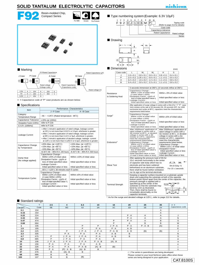
CAT.8100S
Keeping a capacitor surface-mounted on a substrate upsidedown and supporting the substrate at both of the oppositebottom points 45mm apart from the center of the capacitor, thepressure strength is applied with aspecified jig at the center of thesubstrate so that the substrate maybend by 1mm as illustrated.Then, there shall be found noremarkable abnormality on thecapacitor terminals.
Case code L W1 W2 H S
J 1.6 ± 0.1 0.8 ± 0.1 0.6 ± 0.1 0.8 ± 0.1 0.4 ± 0.1P 2.0 ± 0.2 1.25 ± 0.1 0.9 ± 0.1 1.1 ± 0.1 0.5 ± 0.2A 3.2 ± 0.2 1.6 ± 0.2 1.2 ± 0.1 1.1 ± 0.1 0.8 ± 0.2B 3.4 ± 0.2 2.8 ± 0.2 2.3 ± 0.1 1.1 ± 0.1 0.8 ± 0.2
SOLID TANTALUM ELECTROLYTIC CAPACITORS
F92 Resin-molded Chip,Compact Series
Capacitance code of “P” case products are as shown below.
Type numbering system (Example: 6.3V 10µF)
Drawing
DimensionsMarking
SpecificationsPerformance Characteristics
J • P Case A • B CaseItem
CategoryTemperature Range –55 ~ +125˚C (Rated temperature : 85˚C)
Capacitance Tolerance ±20% (at 120Hz)
Leakage Current
• After 1 minute's application of rated voltage, leakage current at 20˚C is not more than 0.01CV or 0.5µA, whichever is greater.
• After 1 minute's application of rated voltage, leakage current at 85˚C is not more than 0.1CV or 5µA, whichever is greater.
• After 1 minute's application of derated voltage, leakage current at 125˚C is not more than 0.125CV or 6.3µA, whichever is greater.
Capacitance Changeby Temperature
+20% Max. (at +125˚C) +15% Max. (at +85˚C) --15% Max. (at --55˚C)
+15% Max. (at +125˚C) +10% Max. (at +85˚C) --10% Max. (at --55˚C)
Damp Heat(No voltage applied)
At 40˚C 90 ~ 95% R.H. 240 hours At 40˚C 90 ~ 95% R.H. 500 hoursCapacitance Change...
Within ±20% of initial valueDissipation Factor...150% or
Iess of initial specified value Leakage Current...
Initial specified value or less
Capacitance Change...Within ±10% of initial value(J case Within ±20%)
Dissipation Factor...150% ofIess of initial specified value *1
Leakage Current...Initial specified value or less
Within ±10% of initial value
Initial specified value or less
Initial specified value or less
Within ±5% of initial value
Initial specified value or less
Initial specified value or less
Temperature Cycles
--55˚C / +125˚C 30 minutes each 5 cycles
(mm)
Taping code(Refer to page 213 for details)
F1
92
23
04
J5
16
07
68
M9
P10 11
Case codeCapacitance tolerance
Rated Capacitance Rated voltageSeries
L
H
S S
W2
W1
Rated Capacitance
Rated voltage(Voltage code)
P Case A CaseJ Case B Case
Rated Capacitance(Capacitance code)
Rated voltage (V)
Rated Capacitance (µF)
AS G226 2210V
J
2.5V e
GJ
EV4V
6.3V
25V35V
10V ACD
16V20V
∗ As for the surge and derated voltage at 125˚C, refer to page 212 for details.
Capacitance Change...
Within ±10% of initial value(J case within ±20%)
Dissipation Factor...150% ofIess of initial specified value*1
Leakage Current...
Initial specified value or less
Within ±5% of initial value
Initial specified value or less
Initial specified value or less
Capacitance Change...
Within ±10% of initial value(J case within ±20%)Dissipation Factor...150% or
Iess of initial specified value*1Leakage Current...
Initial specified value or less
After 1000hours' application ofrated voltage in series with a3Ω resistor at 85˚C, or deratedvoltage in series with a 3Ωresistor at 125˚C, capacitorsmeet the characteristicrequirements listed below.Capacitance Change...
Within ±10˚C of initial value(J case within ±20%) Dissipation Factor...150% or
less of initial specified value*1Leakage Current...Initial specified value or less(J case 2 times value or less)
After 2000hours' application ofrated voltage in series with a3Ω resistor at 85˚C, or deratedvoltage in series with a 3Ωresistor at 125˚C, capacitorsmeet the characteristicrequirements listed below.Capacitance Change...
Within ±10˚C of initial valueDissipation Factor...
Initial specified value or lessLeakage Current...Initial specified value or less
Within ±5% of initial value
Initial specified value or less
Initial specified value or less
Resistance
to Soldering Heat
5 seconds immension at 260˚C,10 seconds reflow at 260˚C
Surge∗
Endurance∗
After application of surge voltage in series with a 33Ω (For “J” “P” case:1kΩ) resistor at the rate of 30 seconds ON, 30 seconds OFF, for 1000successive test cycles at 85˚C, capacitors meet the characteristicsrequirements listed below.
After applying the pressure load of 5N for10±1 seconds horizontally to the centerof capacitor side body which has noelectrode and has been solderedbeforehand on an aluminum substrate,there shall be found neither exfoliationnor its sign at the terminal electrode.
Terminal Strength
Shear Test 5N (0.51kg • f)
For 10 ± 1seconds
20R230
45 45
1mm
refer to P.216Dissipation Factor (120Hz)refer to P.216E.S.R. (100kHz)
2.5 4 6.3 10 16 20 25 350E 0G 0J 1A 1C 1D 1E 1V
0.1 104 A0.15 154 A0.22 224 P · A A A J0.33 334 P · A A A N0.47 474 P P · A A B S0.68 684 P A B B W1 105 P P J · P · A P · A P · A · B (A) A1.5 155 P P · A P · A A · B E2.2 225 P J · P · A J · P · A P · A · B A · B (B) (B) J3.3 335 P · A P · A P · A A · B B N4.7 475 P J · P · A J · P · A P · A A · B B S6.8 685 P J · P · A P · A P · A B w
10 106 J · P · A J · P · A J · P · A P · A · B (A) · B a15 156 P · A P · A P · A A · B e22 226 P · A P · A P · A · B (A) · B (B) j33 336 P · A (P) · A · B (A) · B B n47 476 B (A) · B B68 686 B B
100 107 B B (B)
V
Cap.(µF) Code Capacitance code
Standard ratings
( ) The series in parentheses are being developed.
Please contact to your local Nichicon sales office when theseseries are being designed in your application.

CAT.8100S
SOLID TANTALUM ELECTROLYTIC CAPACITORS
F92Standard ratings
4.7 P F920E475MPA 0.5 8 6.06.8 P F920E685MPA 0.5 10 6.010 J F920E106MJA 0.5 20 6.510 P F920E106MPA 0.5 10 6.010 A F920E106MAA 0.5 8 4.015 P F920E156MPA 0.5 10 5.015 A F920E156MAA 0.5 8 4.022 P F920E226MPA 0.6 20 4.022 A F920E226MAA 0.6 12 2.833 P F920E336MPA 0.8 20 4.033 A F920E336MAA 0.8 12 2.847 B F920E476MBA 1.2 12 1.768 B F920E686MBA 1.7 12 1.5100 B F920E107MBA 2.5 18 1.32.2 P F920G225MPA 0.5 8 12.03.3 P F920G335MPA 0.5 8 12.03.3 A F920G335MAA 0.5 6 7.04.7 J F920G475MJA 0.5 20 8.54.7 P F920G475MPA 0.5 8 6.04.7 A F920G475MAA 0.5 6 4.06.8 J F920G685MJA 0.5 20 7.56.8 P F920G685MPA 0.5 10 6.06.8 A F920G685MAA 0.5 6 4.010 J F920G106MJA 0.5 20 6.510 P F920G106MPA 0.5 10 6.010 A F920G106MAA 0.5 8 4.015 P F920G156MPA 0.6 10 5.015 A F920G156MAA 0.6 8 4.022 P F920G226MPA 0.9 20 5.022 A F920G226MAA 0.9 12 2.833 A F920G336MAA 1.3 12 2.833 B F920G336MBA 1.3 12 1.747 B F920G476MBA 1.9 12 1.768 B F920G686MBA 2.7 18 1.5100 B F920G107MBA 4.0 18 1.3
1 P F920J105MPA 0.5 8 12.01.5 P F920J155MPA 0.5 8 12.02.2 J F920J225MJA 0.5 20 17.52.2 P F920J225MPA 0.5 8 12.02.2 A F920J225MAA 0.5 6 7.03.3 P F920J335MPA 0.5 8 12.03.3 A F920J335MAA 0.5 6 7.04.7 J F920J475MJA 0.5 20 8.54.7 P F920J475MPA 0.5 8 6.04.7 A F920J475MAA 0.5 6 4.06.8 P F920J685MPA 0.5 10 6.06.8 A F920J685MAA 0.5 6 4.010 J F920J106MJA 0.6 20 8.510 P F920J106MPA 0.6 10 6.010 A F920J106MAA 0.6 8 4.015 P F920J156MPA 0.9 10 6.015 A F920J156MAA 0.9 8 4.022 P F920J226MPA 1.4 20 5.022 A F920J226MAA 1.4 12 2.822 B F920J226MBA 1.4 8 1.933 B F920J336MBA 2.1 12 1.747 B F920J476MBA 3.0 12 1.7
Part NumberLeakageCurrent
(µA)
DisspationFactor
(%@120Hz)Case size E.S.R.
(Ω@100kHz)
2.5V
4V
6.3V
Rated Volt(V)
RatedCapacitance
(µF)
1 P F921A105MPA 0.5 8 12.01.5 P F921A155MPA 0.5 8 12.01.5 A F921A155MAA 0.5 6 7.42.2 J F921A225MJA 0.5 20 17.52.2 P F921A225MPA 0.5 8 12.02.2 A F921A225MAA 0.5 6 7.03.3 P F921A335MPA 0.5 8 12.03.3 A F921A335MAA 0.5 6 7.04.7 P F921A475MPA 0.5 8 6.04.7 A F921A475MAA 0.5 6 4.06.8 P F921A685MPA 0.7 8 6.06.8 A F921A685MAA 0.7 6 4.010 P F921A106MPA 1.0 14 6.010 A F921A106MAA 1.0 8 4.010 B F921A106MBA 1.0 6 2.015 A F921A156MAA 1.5 8 4.015 B F921A156MBA 1.5 6 2.022 B F921A226MBA 2.2 8 1.933 B F921A336MBA 3.3 12 1.9
0.47 P F921C474MPA 0.5 8 20.00.68 P F921C684MPA 0.5 8 12.0
1 J F921C105MJA 0.5 20 25.51 P F921C105MPA 0.5 8 12.01 A F921C105MAA 0.5 4 10.0
1.5 P F921C155MPA 0.5 8 12.01.5 A F921C155MAA 0.5 6 7.42.2 P F921C225MPA 0.5 8 12.02.2 A F921C225MAA 0.5 6 7.02.2 B F921C225MBA 0.5 6 3.03.3 A F921C335MAA 0.5 6 7.03.3 B F921C335MBA 0.5 6 3.04.7 A F921C475MAA 0.8 6 7.04.7 B F921C475MBA 0.8 6 3.06.8 B F921C685MBA 1.1 6 3.010 B F921C106MBA 1.6 6 2.0
0.22 P F921D224MPA 0.5 8 20.00.22 A F921D224MAA 0.5 4 10.00.33 P F921D334MPA 0.5 8 20.00.33 A F921D334MAA 0.5 4 10.00.47 P F921D474MPA 0.5 8 20.00.47 A F921D474MAA 0.5 4 10.00.68 A F921D684MAA 0.5 4 10.0
1 P F921D105MPA 0.5 8 20.01 A F921D105MAA 0.5 4 10.0
1.5 A F921D155MAA 0.5 6 7.41.5 B F921D155MBA 0.5 6 4.02.2 A F921D225MAA 0.5 6 7.02.2 B F921D225MBA 0.5 6 3.03.3 B F921D335MBA 0.7 6 3.04.7 B F921D475MBA 0.9 6 3.00.22 A F921E224MAA 0.5 4 10.00.33 A F921E334MAA 0.5 4 10.00.47 A F921E474MAA 0.5 4 10.00.68 B F921E684MBA 0.5 4 4.0
1 P F921E105MPA 0.5 8 20.01 A F921E105MAA 0.5 6 10.01 B F921E105MBA 0.5 4 4.0
0.10 A F921V104MAA 0.5 4 10.00.15 A F921V154MAA 0.5 4 10.00.22 A F921V224MAA 0.5 4 10.00.33 A F921V334MAA 0.5 4 10.00.47 B F921V474MBA 0.5 4 4.00.68 B F921V684MBA 0.5 4 4.0
Part NumberLeakageCurrent
(µA)
DisspationFactor
(%@120Hz)Case size E.S.R.
(Ω@100kHz)
10V
16V
20V
25V
35V
Rated Volt(V)
RatedCapacitance
(µF)
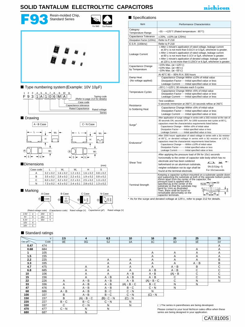
CAT.8100S
0.470.6811.52.23.34.76.8
101522334768
100150220330470680
474684105155225335475685106156226336476686107157227337477687
AAA
A • BBB
B • CC
C • N
AAAA
A • BA • BA • BA • BA • B
(A) • B • CB • CC • N
NN
AAAAA
A • BA • BA • BA • BB • CB • C
(B) • C • NC • N
NN
AAAA
A • BA • BA • B
(A) • B • CB • CC • NC • N
(C) • NNN
AAAAA
A • BA • BA • B
(A) • B • CB • CC • N
N(C) • N
AAAA
A • BA • B(A) • B
CCNN
AAAA
A • BBCCCNN
AAAABBCCCNN
2.50E
40G
6.30J
101A
161C
201D
251E
351V
V
SOLID TANTALUM ELECTROLYTIC CAPACITORS
F93 Resin-molded Chip,Standard Series
∗ As for the surge and derated voltage at 125˚C, refer to page 212 for details.
Type numbering system (Example: 10V 10µF)
Drawing
Dimensions
Marking
Specifications
Performance CharacteristicsItem
CategoryTemperature Range --55 ~ +125˚C (Rated temperature : 85˚C)
Capacitance Tolerance ±20%, ±10% (at 120Hz) Dissipation Factor (120Hz) Refer to P.218
E.S.R. (100kHz) Refer to P.218
Leakage Current
• After 1 minute's application of rated voltage, leakage current at 20˚C is not more than 0.01CV or 0.5µA, whichever is greater.
• After 1 minute's application of rated voltage, leakage current at 85˚C is not more than 0.1CV or 5µA, whichever is greater.
• After 1 minute's application of derated voltage, leakage current at 125˚C is not more than 0.125CV or 6.3µA, whichever is greater.
Capacitance Changeby Temperature
+15% Max. (at +125˚C) +10% Max. (at +85˚C) --10% Max. (at --55˚C)
Damp Heat(No voltage applied)
At 40˚C 90 ~ 95% R.H. 500 hoursCapacitance Change Within ±10% of initial valueDissipation Factor......Initial specified value or lessLeakage Current........Initial specified value or less
Temperature Cycles
--55˚C / +125˚C 30 minutes each 5 cyclesCapacitance Change Within ±5% of initial valueDissipation Factor......Initial specified value or lessLeakage Current........Initial specified value or less
Resistance
to Soldering Heat
Test condition:5 seconds immersion at 260˚C,10 seconds reflow at 260˚C
Capacitance Change Within ±5% of initial valueDissipation Factor......Initial specified value or lessLeakage Current........Initial specified value or less
Surge∗
After application of surge voltage in series with a 33Ω resistor at the rate of30 seconds ON, seconds OFF, for 1000 sucessive test cycles at 85˚C,capacitors meet the characteristics requirements listed below.
Capacitance Change....Within ±5% of initial valueDissipation Factor........Initial specified value or lessLeakage Current..........Initial specified value or less
Endurance∗
After 2000 hours' application of rated voltage in series with a 3Ω resistorat 85˚C, or derated voltage in series with a 3Ω resistor at 125˚C,capacitors meet the characteristic requirements listed below.
Capacitance Change......Within ±10% of initial valueDissipation Factor..........Initial specified value or lessLeakage Current............Initial specified value or less
Shear Test
After applying the pressure load of 5N for 10±1 secondshorizontally to the center of capacitor side body which has noelectrode and has been solderedbeforehand on an aluminum substrate,neigher exfoliation not its sign shall befound at the terminal electrode.
Terminal Strength
Keeping a capacitor surface-mounted on a substrate upside downand supporting the substrate at both of the opposite bottom points45mm apart from the center of the capacitor, thepressure load is applied with aspecified jig at the center of thesubstrate so that the substrate maybend by 1mm as illustrated.Then, there shall be found noremarkable abnormality on thecapacitor terminals.
Case code L W1 W2 H SA 3.2 ± 0.2 1.6 ± 0.2 1.2 ± 0.1 1.6 ± 0.2 0.8 ± 0.2B 3.5 ± 0.2 2.8 ± 0.2 2.2 ± 0.1 1.9 ± 0.2 0.8 ± 0.2C 6.0 ± 0.2 3.2 ± 0.2 2.2 ± 0.1 2.5 ± 0.2 1.3 ± 0.2N 7.3 ± 0.2 4.3 ± 0.2 2.4 ± 0.1 2.8 ± 0.2 1.3 ± 0.2
(mm)
( ) The series in parentheses are being developed.
Please contact to your local Nichicon sales office when theseseries are being designed in your application.
Taping code(Refer to page 213 for details)
F1
92
33
14
A5
16
07
68
M9
A10 11
Case codeCapacitance tolerance
Rated Capacitance Rated voltageSeries
L
H
S S
W2
W1 L
H
S S
W2
W1
A • B Case C • N Case
Capacitance (µF)Rated voltage (V) Rated voltage (V)
A Case B Case C Case N Case
(Rated voltage code) (Capacitance code)
C685 2216V 47 16
V
100
16V
2.5V eGJAC
4V6.3V10V16V
20V DEV
25V35V
5N (0.51kg • f)
For 10±1seconds
20R230
45 45
1mm
Standard ratings
Cap. (µF) Code
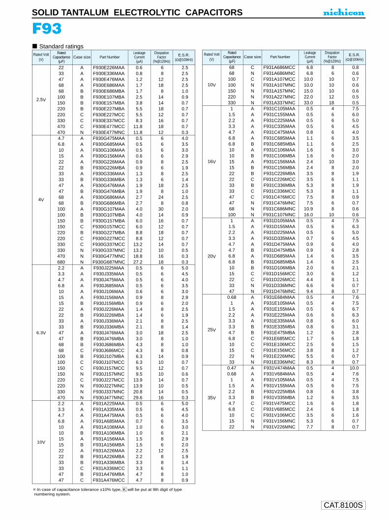
CAT.8100S
SOLID TANTALUM ELECTROLYTIC CAPACITORS
F93Standard ratings
22 A F930E226MAA 0.6 6 2.533 A F930E336MAA 0.8 8 2.547 A F930E476MAA 1.2 12 2.568 A F930E686MAA 1.7 18 2.568 B F930E686MBA 1.7 8 1.0100 B F930E107MBA 2.5 14 0.9150 B F930E157MBA 3.8 14 0.7220 B F930E227MBA 5.5 18 0.7220 C F930E227MCC 5.5 12 0.7330 C F930E337MCC 8.3 16 0.7470 C F930E477MCC 11.8 18 0.7470 N F930E477MNC 11.8 12 0.34.7 A F930G475MAA 0.5 6 4.06.8 A F930G685MAA 0.5 6 3.510 A F930G106MAA 0.5 6 3.015 A F930G156MAA 0.6 6 2.922 A F930G226MAA 0.9 8 2.522 B F930G226MBA 0.9 6 1.933 A F930G336MAA 1.3 8 2.533 B F930G336MBA 1.3 6 1.447 A F930G476MAA 1.9 18 2.547 B F930G476MBA 1.9 8 1.068 A F930G686MAA 2.7 24 2.568 B F930G686MBA 2.7 8 0.8100 A F930G107MAA 4.0 30 2.0100 B F930G107MBA 4.0 14 0.9150 B F930G157MBA 6.0 16 0.7150 C F930G157MCC 6.0 12 0.7220 B F930G227MBA 8.8 18 0.7220 C F930G227MCC 8.8 12 0.7330 C F930G337MCC 13.2 14 0.7330 N F930G337MNC 13.2 10 0.5470 N F930G477MNC 18.8 16 0.3680 N F930G687MNC 27.2 18 0.32.2 A F930J225MAA 0.5 6 5.03.3 A F930J335MAA 0.5 6 4.54.7 A F930J475MAA 0.5 6 4.06.8 A F930J685MAA 0.5 6 3.510 A F930J106MAA 0.6 6 3.015 A F930J156MAA 0.9 8 2.915 B F930J156MBA 0.9 6 2.022 A F930J226MAA 1.4 8 2.522 B F930J226MBA 1.4 6 1.933 A F930J336MAA 2.1 8 2.533 B F930J336MBA 2.1 8 1.447 A F930J476MAA 3.0 18 2.547 B F930J476MBA 3.0 8 1.068 B F930J686MBA 4.3 8 1.068 C F930J686MCC 4.3 8 0.8100 B F930J107MBA 6.3 14 0.9100 C F930J107MCC 6.3 10 0.7150 C F930J157MCC 9.5 12 0.7150 N F930J157MNC 9.5 10 0.6220 C F930J227MCC 13.9 14 0.7220 N F930J227MNC 13.9 10 0.5330 N F930J337MNC 20.8 14 0.5470 N F930J477MNC 29.6 16 0.32.2 A F931A225MAA 0.5 6 5.03.3 A F931A335MAA 0.5 6 4.54.7 A F931A475MAA 0.5 6 4.06.8 A F931A685MAA 0.7 6 3.510 A F931A106MAA 1.0 6 3.010 B F931A106MBA 1.0 6 2.115 A F931A156MAA 1.5 8 2.915 B F931A156MBA 1.5 6 2.022 A F931A226MAA 2.2 12 2.522 B F931A226MBA 2.2 8 1.933 B F931A336MBA 3.3 8 1.433 C F931A336MCC 3.3 6 1.147 B F931A476MBA 4.7 8 1.047 C F931A476MCC 4.7 8 0.9
Part NumberLeakageCurrent
(µA)
DisspationFactor
(%@120Hz)Case size E.S.R.
(Ω@100kHz)
2.5V
4V
6.3V
10V
Rated Volt(V)
RatedCapacitance
(µF)
68 C F931A686MCC 6.8 8 0.868 N F931A686MNC 6.8 6 0.6100 C F931A107MCC 10.0 10 0.7100 N F931A107MNC 10.0 10 0.6150 N F931A157MNC 15.0 10 0.6220 N F931A227MNC 22.0 12 0.5330 N F931A337MNC 33.0 18 0.51 A F931C105MAA 0.5 4 7.5
1.5 A F931C155MAA 0.5 6 6.02.2 A F931C225MAA 0.5 6 5.03.3 A F931C335MAA 0.5 6 4.54.7 A F931C475MAA 0.8 6 4.06.8 A F931C685MAA 1.1 6 3.56.8 B F931C685MBA 1.1 6 2.510 A F931C106MAA 1.6 6 3.010 B F931C106MBA 1.6 6 2.015 A F931C156MAA 2.4 10 3.015 B F931C156MBA 2.4 8 2.022 B F931C226MBA 3.5 8 1.922 C F931C226MCC 3.5 6 1.133 B F931C336MBA 5.3 8 1.933 C F931C336MCC 5.3 8 1.147 C F931C476MCC 7.5 8 0.947 N F931C476MNC 7.5 6 0.768 N F931C686MNC 10.9 8 0.6100 N F931C107MNC 16.0 10 0.61 A F931D105MAA 0.5 4 7.5
1.5 A F931D155MAA 0.5 6 6.32.2 A F931D225MAA 0.5 6 5.03.3 A F931D335MAA 0.7 6 4.54.7 A F931D475MAA 0.9 6 4.04.7 B F931D475MBA 0.9 6 2.86.8 A F931D685MAA 1.4 6 3.56.8 B F931D685MBA 1.4 6 2.510 B F931D106MBA 2.0 6 2.115 C F931D156MCC 3.0 6 1.222 C F931D226MCC 4.4 8 1.133 N F931D336MNC 6.6 6 0.747 N F931D476MNC 9.4 8 0.7
0.68 A F931E684MAA 0.5 4 7.61 A F931E105MAA 0.5 4 7.5
1.5 A F931E155MAA 0.5 6 6.72.2 A F931E225MAA 0.6 6 6.33.3 A F931E335MAA 0.8 6 6.03.3 B F931E335MBA 0.8 6 3.14.7 B F931E475MBA 1.2 6 2.86.8 C F931E685MCC 1.7 6 1.810 C F931E106MCC 2.5 6 1.515 C F931E156MCC 3.8 8 1.222 N F931E226MNC 5.5 6 0.733 N F931E336MNC 8.3 8 0.7
0.47 A F931V474MAA 0.5 4 10.00.68 A F931V684MAA 0.5 4 7.6
1 A F931V105MAA 0.5 4 7.51.5 A F931V155MAA 0.5 6 7.52.2 B F931V225MBA 0.8 6 3.83.3 B F931V335MBA 1.2 6 3.54.7 C F931V475MCC 1.6 6 1.86.8 C F931V685MCC 2.4 6 1.810 C F931V106MCC 3.5 6 1.615 N F931V156MNC 5.3 6 0.722 N F931V226MNC 7.7 8 0.7
Part NumberLeakageCurrent
(µA)
DisspationFactor
(%@120Hz)Case size E.S.R.
(Ω@100kHz)
10V
16V
20V
25V
35V
Rated Volt(V)
RatedCapacitance
(µF)
In case of capacitance tolerance ±10% type, K will be put at 9th digit of type numbering system.
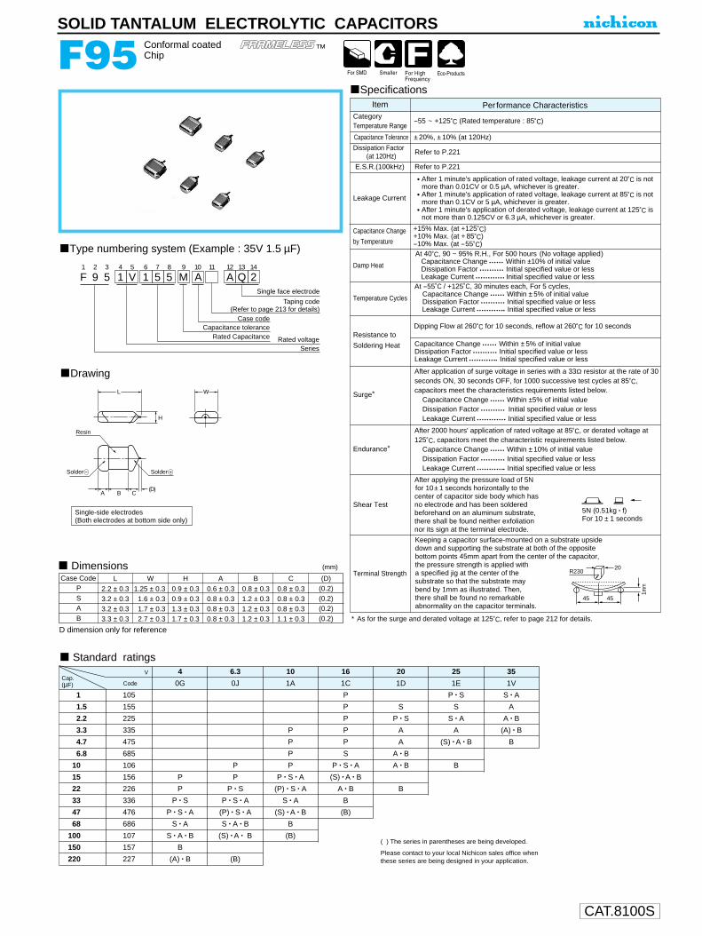
CAT.8100S
After applying the pressure load of 5Nfor 10±1 seconds horizontally to the center of capacitor side body which hasno electrode and has been soldered beforehand on an aluminum substrate, there shall be found neither exfoliationnor its sign at the terminal electrode.
4 6.3 10 16 20 25 35
0G 0J 1A 1C 1D 1E 1V
1 105 P P • S S • A
1.5 155 P S S A
2.2 225 P P • S S • A A • B
3.3 335 P P A A (A) • B
4.7 475 P P A (S) • A • B B
6.8 685 P S A • B
10 106 P P P • S • A A • B B
15 156 P P P • S • A (S) • A • B
22 226 P P • S (P) • S • A A • B B
33 336 P • S P • S • A S • A B
47 476 P • S • A (P) • S • A (S) • A • B (B)
68 686 S • A S • A • B B
100 107 S • A • B (S) • A • B (B)
150 157 B
220 227 (A) • B (B)
V
• After 1 minute's application of rated voltage, leakage current at 20˚C is notmore than 0.01CV or 0.5 µA, whichever is greater.
• After 1 minute's application of rated voltage, leakage current at 85˚C is notmore than 0.1CV or 5 µA, whichever is greater.
• After 1 minute's application of derated voltage, leakage current at 125˚C isnot more than 0.125CV or 6.3 µA, whichever is greater.
Dipping Flow at 260˚C for 10 seconds, reflow at 260˚C for 10 seconds
+15% Max. (at +125˚C) +10% Max. (at + 85˚C) --10% Max. (at --55˚C)
Damp Heat
Temperature Cycles
At 40˚C, 90 ~ 95% R.H., For 500 hours (No voltage applied)Capacitance Change • • • • • • Within ±10% of initial valueDissipation Factor • • • • • • • • • • Initial specified value or lessLeakage Current • • • • • • • • • • • • Initial specified value or less
At --55˚C / +125˚C, 30 minutes each, For 5 cycles,Capacitance Change • • • • • • Within ±5% of initial valueDissipation Factor • • • • • • • • • • Initial specified value or lessLeakage Current • • • • • • • • • • •• Initial specified value or less
Resistance to
Soldering Heat Capacitance Change • • • • • • Within ±5% of initial valueDissipation Factor • • • • • • • • • • Initial specified value or lessLeakage Current • • • • • • • • • • •• Initial specified value or less
Endurance∗
After 2000 hours' application of rated voltage at 85˚C, or derated voltage at125˚C, capacitors meet the characteristic requirements listed below.
Capacitance Change • • • • • • Within ±10% of initial valueDissipation Factor • • • • • • • • • • Initial specified value or lessLeakage Current • • • • • • • • • • •• Initial specified value or less
Surge∗
After application of surge voltage in series with a 33Ω resistor at the rate of 30seconds ON, 30 seconds OFF, for 1000 successive test cycles at 85˚C,capacitors meet the characteristics requirements listed below.
Capacitance Change • • • • • • Within ±5% of initial valueDissipation Factor • • • • • • • • • • Initial specified value or lessLeakage Current • • • • • • • • • • • • Initial specified value or less
Shear Test
Terminal Strength
Keeping a capacitor surface-mounted on a substrate upside down and supporting the substrate at both of the opposite bottom points 45mm apart from the center of the capacitor,the pressure strength is applied witha specified jig at the center of thesubstrate so that the substrate may bend by 1mm as illustrated. Then, there shall be found no remarkableabnormality on the capacitor terminals.
5N (0.51kg • f)For 10 ± 1 seconds
SOLID TANTALUM ELECTROLYTIC CAPACITORS
F95 Conformal coatedChip
Specifications
Type numbering system (Example : 35V 1.5 µF)
Drawing
L W
H
Solder Solder
A B C(D)
Resin
Single-side electrodes (Both electrodes at bottom side only)
ItemCategory Temperature Range
Capacitance Tolerance
Dissipation Factor(at 120Hz)
Leakage Current
Capacitance Change
by Temperature
Per formance Characteristics
--55 ~ +125˚C (Rated temperature : 85˚C)
±20%, ±10% (at 120Hz)
Case Code
D dimension only for reference
( ) The series in parentheses are being developed.
Please contact to your local Nichicon sales office whenthese series are being designed in your application.
Dimensions
Refer to P.221
R230
45 45
20
1mm
∗ As for the surge and derated voltage at 125˚C, refer to page 212 for details.
Standard ratings
(mm)
Cap.(µF) Code
Refer to P.221E.S.R.(100kHz)
L
2.2 ± 0.3 1.25 ± 0.3 0.9 ± 0.3 0.6 ± 0.3 0.8 ± 0.3 0.8 ± 0.3
W H A B C (D) (0.2) P
3.2 ± 0.3 1.6 ± 0.3 0.9 ± 0.3 0.8 ± 0.3 1.2 ± 0.3 0.8 ± 0.3 (0.2) S
1.3 ± 0.31.7 ± 0.3
0.8 ± 0.30.8 ± 0.3
1.2 ± 0.31.2 ± 0.3
0.8 ± 0.31.1 ± 0.3
1.7 ± 0.32.7 ± 0.3
3.2 ± 0.33.3 ± 0.3
(0.2) (0.2)
AB
Taping code(Refer to page 213 for details)
Single face electrode
F1
92
53
14
V5
16
57
58
M9
A10 11
A12
Q13
214
Case codeCapacitance tolerance
Rated Capacitance Rated voltageSeries
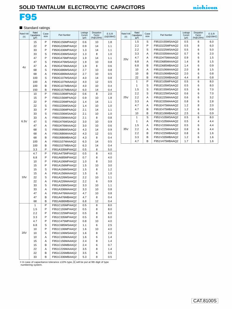
CAT.8100S
SOLID TANTALUM ELECTROLYTIC CAPACITORS
F95Standard ratings
15 P F950G156MPAAQ2 0.6 10 1.8 22 P F950G226MPAAQ2 0.9 14 1.1 33 P F950G336MPAAQ2 1.3 14 1.1 33 S F950G336MSAAQ2 1.3 8 1.0 47 P F950G476MPAAQ2 1.9 14 1.1 47 S F950G476MSAAQ2 1.9 10 0.8 47 A F950G476MAAAQ2 1.9 8 0.6 68 S F950G686MSAAQ2 2.7 10 0.8 68 A F950G686MAAAQ2 2.7 10 0.5
100 S F950G107MSAAQ2 4.0 14 0.8100 A F950G107MAAAQ2 4.0 12 0.5100 B F950G107MBAAQ2 4.0 10 0.4 150 B F950G157MBAAQ2 6.0 14 0.4 10 P F950J106MPAAQ2 0.6 8 2.0 15 P F950J156MPAAQ2 0.9 10 1.8 22 P F950J226MPAAQ2 1.4 14 1.1 22 S F950J226MSAAQ2 1.4 10 1.033 P F950J336MPAAQ2 2.1 14 1.1 33 S F950J336MSAAQ2 2.1 10 1.0 33 A F950J336MAAAQ2 2.1 8 0.8 47 S F950J476MSAAQ2 3.0 10 0.9 47 A F950J476MAAAQ2 3.0 10 0.6 68 S F950J686MSAAQ2 4.3 14 0.9 68 A F950J686MAAAQ2 4.3 12 0.5 68 B F950J686MBAAQ2 4.3 8 0.4
100 A F950J107MAAAQ2 6.3 14 0.5 100 B F950J107MBAAQ2 6.3 14 0.4 3.3 P F951A335MPAAQ2 0.5 8 5.0 4.7 P F951A475MPAAQ2 0.5 8 4.0 6.8 P F951A685MPAAQ2 0.7 8 4.0 10 P F951A106MPAAQ2 1.0 8 3.0 15 P F951A156MPAAQ2 1.5 10 3.0 15 S F951A156MSAAQ2 1.5 8 1.2 15 A F951A156MAAAQ2 1.5 6 1.0 22 S F951A226MSAAQ2 2.2 10 1.1 22 A F951A226MAAAQ2 2.2 6 0.9 33 S F951A336MSAAQ2 3.3 10 1.1 33 A F951A336MAAAQ2 3.3 10 0.8 47 A F951A476MAAAQ2 4.7 10 0.8 47 B F951A476MBAAQ2 4.7 8 0.4 68 B F951A686MBAAQ2 6.8 12 0.4 1 P F951C105MPAAQ2 0.5 8 8.0
1.5 P F951C155MPAAQ2 0.5 8 8.0 2.2 P F951C225MPAAQ2 0.5 8 6.0 3.3 P F951C335MPAAQ2 0.5 8 6.0 4.7 P F951C475MPAAQ2 0.8 10 4.0 6.8 S F951C685MSAAQ2 1.1 6 2.510 P F951C106MPAAQ2 1.6 10 4.0 10 S F951C106MSAAQ2 1.6 8 2.0 10 A F951C106MAAAQ2 1.6 6 1.4 15 A F951C156MAAAQ2 2.4 8 1.4 15 B F951C156MBAAQ2 2.4 6 0.7 22 A F951C226MAAAQ2 3.5 8 1.4 22 B F951C226MBAAQ2 3.5 6 0.5 33 B F951C336MBAAQ2 5.3 8 0.5
4V
6.3V
10V
16V
Part NumberLeakageCurrent
(µA)
DisspationFactor
(%@120Hz)
Casesize
E.S.R(Ω@100kHZ)
Rated Volt(V)
RatedCapacitance
(µF)
1.5 S F951D155MSAAQ2 0.5 6 6.0 2.2 P F951D225MPAAQ2 0.5 8 6.0 2.2 S F951D225MSAAQ2 0.5 6 5.0 3.3 A F951D335MAAAQ2 0.7 6 2.0 4.7 A F951D475MAAAQ2 0.9 6 1.5 6.8 A F951D685MAAAQ2 1.4 8 1.5 6.8 B F951D685MBAAQ2 1.4 6 0.9 10 A F951D106MAAAQ2 2.0 8 1.5 10 B F951D106MBAAQ2 2.0 6 0.8 22 B F951D226MBAAQ2 4.4 8 0.8 1 P F951E105MPAAQ2 0.5 6 8.01 S F951E105MSAAQ2 0.5 6 8.0
1.5 S F951E155MSAAQ2 0.5 6 7.02.2 S F951E225MSAAQ2 0.6 6 7.0 2.2 A F951E225MAAAQ2 0.6 6 3.2 3.3 A F951E335MAAAQ2 0.8 6 2.8 4.7 A F951E475MAAAQ2 1.2 8 2.0 4.7 B F951E475MBAAQ2 1.2 6 0.9 10 B F951E106MBAAQ2 2.5 6 0.9 1 S F951V105MSAAQ2 0.5 6 8.0 1 A F951V105MAAAQ2 0.5 4 4.4
1.5 A F951V155MAAAQ2 0.5 6 4.4 2.2 A F951V225MAAAQ2 0.8 6 4.4 2.2 B F951V225MBAAQ2 0.8 6 1.6 3.3 B F951V335MBAAQ2 1.2 6 1.6 4.7 B F951V475MBAAQ2 1.7 6 1.6
20V
25V
35V
Part NumberLeakageCurrent
(µA)
DisspationFactor
(%@120Hz)
Casesize
E.S.R(Ω@100kHZ)
Rated Volt(V)
RatedCapacitance
(µF)
In case of capacitance tolerance ±10% type, K will be put at 9th digit of type numbering system.

CAT.8100S
5N (0.51kg • f)For 10 ± 1 seconds
F97 Resin-molded Chip,High Reliability(High temperature /moisture resistance) Series
SOLID TANTALUM ELECTROLYTIC CAPACITORS
Type numbering system (Example : 16V 3.3 µF)
Dimensions
Marking
Standard ratings
Drawing
Specifications
Taping code(Refer to page 213 for details)
F1
92
73
14
C5
36
37
58
M9
B10 11
Case codeCapacitance tolerance
Rated Capacitance Rated voltageSeries
C • N CaseA • B Case
L
H
S
W1
W2
S
L
H
S
W1
W2
S
A Case B Case C Case
C105 3.316r 10 16
r
Rated voltage(Voltage code)
Rated Capacitance(Capacitance code ) Rated voltage (V) Rated Capacitance (µF)
Month code
N Case
47
10r
0.1
0.15
0.22
0.33
0.47
0.68
1
1.5
2.2
3.3
4.7
6.8
10
15
22
33
47
68
100
150
104
154
234
334
474
684
105
155
225
335
475
685
106
156
226
336
476
686
107
157
A
A
A
B
B
B
C
C
C • N
N
N
A
A
A
B
B
B
C
C
C • N
N
N
A
A
A
B
B
B
C
C
C • N
N
A
A
B
B
C
C
N
N
A
A
B
B
C
C
N
N
A
A
B
C
C
N
N
A
A
A
A
B
B
B
C
C
C
N
N
N
40G
6.30J
101A
161C
201D
251E
351VCode
V
Case code
A
B
C
N
L W1 W2 H S
(mm)
3.2 ± 0.2
3.5 ± 0.2
6.0 ± 0.2
7.3 ± 0.2
1.6 ± 0.2
2.8 ± 0.2
3.2 ± 0.2
4.3 ± 0.2
1.2 ± 0.1
2.2 ± 0.1
2.2 ± 0.1
2.4 ± 0.1
1.6 ± 0.2
1.9 ± 0.2
2.5 ± 0.2
2.8 ± 0.2
0.8 ± 0.2
0.8 ± 0.2
1.3 ± 0.2
1.3 ± 0.2
Cap.(µF)
Item
--55 ~ +125˚C (Rated temperature : 85˚C.) CategoryTemperature Range
Capacitance Tolerance
Dissipation Factor
Performance Characteristics
±20%, ±10% (at 120Hz)
~1.5 µF 4% Max.2.2 ~68 µF 6% Max. (at 120Hz) 100 µF~ 8% Max.
Leakage Current∗
• After 1 minute' s application of rated voltage,leakage current at 20˚Cis not more than 0.01CV or 0.5µA, whichever is greater.
• After 1 minute' s application of rated voltage,leakage current at 85˚Cis not more than 0.1CV or 5µA,whichever is greater.
• After 1 minute' s application of derated voltage,leakage current at125˚C is not more than 0.125CV or 6.3µA,whichever is greater.
Capacitance Changeby Temperature
+15% Max. (at +125˚C) +10% Max. (at +85˚C) --10% Max. (at --55˚C)
Damp Heat
At 85˚C, 85% R.H.,For 1000 hours (No voltage applied)Capacitance Change • • • • • • Within ±10% of initial valueDissipation Factor • • • • • • • • • • • Initial specified value or lessLeakage Current • • • • • • • • • • • • 125% or less of initial specified value
Load Humidity
After 500 hour' s application of rated voltage in series with a 33Ωresistor at 60˚C,90~95% R.H.,capacitors meet the characteristicsrequirements listed below.
Capacitance Change • • • • • • Within ±10% of initial valueDissipation Factor • • • • • • • • • • Initial specified value or lessLeakage Current • • • • • • • • • • • • 125% or less of initial specified value
Temperature Cycles
At --55˚C / +125˚C,For 30 minutes each,1000 cycles Capacitance Change • • • • • • Within ±5% of initial valueDissipation Factor • • • • • • • • • • • Initial specified value or lessLeakage Current • • • • • • • • • • • • • Initial specified value or less
Resistance
to Soldering Heat
At 260˚C,reflowing capacitors for 10 seconds Max.Capacitance Change • • • • • • Within ±5% of initial valueDissipation Factor • • • • • • • • • • • Initial specified value or lessLeakage Current • • • • • • • • • • • • • Initial specified value or less
SolderabilityAfter immersing capacitors completely into a solder pot at245˚C for 2~3 seconds,more than 3/4 of their electrode areashall remain covered with new solder.
Surge∗
After application of surge in series with a 33Ω resistor at therate of 30 seconds ON, 30 seconds OFF,for 1000 successivetest cycles at 85˚C,capacitors meet the characteristicsrequirements listed below.
Capacitance Change • • • • • • Within ±5% of initial valueDissipation Factor • • • • • • • • • • • Initial specified value or lessLeakage Current • • • • • • • • • • • • • Initial specified value or less
Endurance∗
After 2000 hours' application of rated voltage in series with a3Ω resistor at 85˚C,or derated voltage in series with a 3Ωresistor at 125˚C,capacitors meet the characteristicrequirements listed below.
Capacitance Change • • • • • • Within ±10% of initial valueDissipation Factor • • • • • • • • • • • Initial specified value or lessLeakage Current • • • • • • • • • • • • • Initial specified value or less
Shear Test
After Applying the pressure load of 5Nfor 10 ±1 seconds horizontally to thecenter of capacitor side body whichhas no electrode and has beensoldered beforehand on an aluminumsubstrate,there shall be found neitherexfoliation nor its sign at the terminalelectrode.
Terminal Strength
Keeping a capacitor surface-mounted on a substrate upsidedown and supporting the substrate at both of the oppositebottom points 45mm apart from the center of the capacitor, thepressure strength is applied with aspecified jig at the center of thesubstrate so that the substrate maybend by 1mm as illustrated.Then,there shall be found noremarkable abnormality on thecapacitor terminals.
∗ As for the surge and derated voltage at 125˚C, refer to page 212 for details.
45 45
R23020
1mm

CAT.8100S
F98Specifications
Type numbering system (Example : 6.3V 10 µF)
Drawing
L W1 S2W2 H S1
M 1.6 ± 0.1 0.85 ± 0.1 0.65 ± 0.1 0.8 ± 0.1 0.5 ± 0.1 0.6 ± 0.1
(mm)
Cace Code
L
H
W1
W2
S1S2S1
Rated voltage(Voltage code)
J
Taping code(Refer to page 213 for details)
F1
92
83
04
J5
16
07
68
M9
M10 11
Case codeCapacitance tolerance
Rated Capacitance Rated voltageSeries
Marking
Standard ratings
CategoryTemperature Range
Capacitance Tolerance
Leakage Current
Dissipation Factor(120Hz)
Damp Heat
Temperature Cycles
Resistance to Soldening Heat
Surge∗
Endurance∗
Shear Test
Terminal Strength
Performance Characteristics
±20% (at 120Hz)
Refer to the list below.
After 5 minute's application of rated voltage, leakage current at 20°C is not more than 0.1CV or 0.5µA, whichever is greater.
At 40°C, 90 ~ 95% R.H., For 500hours (No voltage applied)Capacitance Change Within ±30% of initial valueDissipation Factor 150% or less of initial specified valueLeakage Current 200% or less of initial specified value
At --55°C / +125°C, For 30 minutes each, 5 cyclesCapacitance Change Within ±30% of initial valueDissipation Factor 150% or less of initial specified valueLeakage Current Initial specified value or less
At 260°C, For 10 seconds, Reflow,Capacitance Change Within ±30% of initial valueLeakage Current Initial specified value or lessLeakage Current Initial specified value or less
After application of surge in series with a 1kΩ resistor at the rate of 30 seconds ON, 30 seconds OFF, for 1000 successive test cycles at 85°C, capacitors meet the characteristics requirements listed below.
Capacitance Change Within ±30% initial valueDissipation Factor 150% or less of initial specified valueLeakage Current 200% or less of initial specified value
After 1000 hours' application of rated voltage in series with a 3Ω resistor at 85°C, capacitors meet the characteristic requirements listed below
Capacitance Change Within ±30% of initial valueDissipation Factor 150% or less of initial specified valueLeakage Current 200% or less of initial specified value
After applying the pressure load of 5N for 10±1 seconds horizontally to the center of capacitor side body which has no electrode and has been soldered beforehand on an aluminum substrate, there shall be found neither exfoliation nor its sign at the terminal electrode.
Keeping a capacitor surface-mounted on a substrate upside down and supporting the substrate at both of the opposite bottom points 45mm apart from the center of the capacitor, the pressure strength is applied with a specified jig at the center of thesubstrate so that the substrate may bend by 1mm as illustrated.Then, there shall be found no remarkable abnormality on the capacitor terminals.
Item
--55 ~ +125°C (Rated temperature : 85°C)
E.S.R.(100kHz) Refer to the list below.
5N (0.51kg • f)
For 10 ± 1seconds
20R230
45 45
1mm
Resin-molded Chip,High Capacitance Series
∗ As for the surge and derated voltage at 125˚C, refer to page 212 for details.
SOLID TANTALUM ELECTROLYTIC CAPACITORS
( )The series in parentheses are being developed.Please contact to your local Nichicon sales office whenthese series are being designed in your application.
8881082020
1582062066
2210224.7101
2.2
Part Number
0.90.61.40.51.00.50.5
LeakageCurrent
(µA)
E.S.R.(mΩ@100kHz)
DisspationFactor
(%@120Hz)
Casesize
4
6.3
10
16
Rated Volt(V)
RatedCapacitance
(µF)
F980G226MMAF980J106MMAF980J226MMAF981A475MMAF981A106MMAF981C105MMAF981C225MMA
MMMMMMM
1
2.2
4.7
10
22
33
47
105
225
475
106
226
336
476 (M)
M
(M)
M
M
M
M
M
M
2.5 4 6.3 10 160E 0G 0J 1A 1C
VCodeCap.(µF)

CAT.8100S
For capacitance of more than 1000µF add 0.02 for every increase of 1000µF.
ALUMINUM ELECTROLYTIC CAPACITORS
FG series
High Grade Type, For Audio Equipment
Type numbering system (Example : 10V 47µF)
Specifications
Category Temperature Range
Rated Voltage Range
Rated Capacitance Range
Capacitance Tolerance
Leakage Current
tan δ
Stability at Low Temperature
Endurance
Shelf Life
Marking
Performance CharacteristicsItem
–40 ~ +85°C6.3 ~ 100V
0.1 ~ 10000µF±20% at 120Hz, 20°CAfter 1 minute's application of rated voltage, leakage current is not more than 0.01CV or 3 (µA) , whichever is greater.
Printed with black color letter on gold sleeve.
Measurement frequency : 120Hz
After 1000 hours'application of rated voltageat 85°C, capacitors meetthe characteristicrequirements listed at right.
After leaving capacitors under no load at 85°C for 1000 hours, they meet the specifiedvalue for endurance characteristics listed above.
Rated voltage (V)
tan δ (MAX.)
6.3
0.22
10
0.19
160.16
250.14
35
0.12
50
0.10
63
0.09
80
0.09
100
0.08
Z–25°C / Z+20°C
Z–40°C / Z+20°C
Rated voltage (V)
Impedance ratioZT / Z20 (MAX.)
6.3
4
8
10
3
6
16
2
4
25
2
4
35
2
3
50
2
3
63
2
3
80
2
3
100
2
3
Capacitance change
Leakage current
tan δ
Within ±20% of the initial measurement for units of not more than 16V or φ6.3Within ±15% of the initial measurement for units of not less than 25V or above φ6.3
150% or less of initial specified value
Initial specified value or less
Measurement frequency : 120Hz, Temperature : 20°C
"Fine Gold" MUSE acoustic series suited for high gradeaudio equipment, using state of the art etching techniques.Rich sound in the bass register and clearer high end, mostsuited for AV equipment like DVD, MD.
L+ MAX 15MIN 4MIN
φD+
0.5
MA
X
P±0
.5
φDPφd
52.00.6
6.32.50.6
83.50.6
105.00.6
12.55.00.8
167.50.8
187.50.8
(φ6.3up)
(L < 20) 1.5(L 20) 2.0
Sleeve φ d
Pressurerelief vent
U1
F2
G3
14
A5
46
77
08
M9
D10
J11
φD
5 DJ
6.3
8 · 10
EJ
PJ
12.5 ~ 18 HJ
Configuration
Capacitance tolerance (±20%)
Rated Capacitance (47µF)
Rated voltage (10V)
Series name
Type
Code
Please contact to us if Eco-Products are required.
Radial Lead Type
Please refer to page 19, 20, 21 about the formed or taped product spec.Please refer to page 3 for the minimum order quantity.
FG FWHigh Grade
Dimension table in next page.
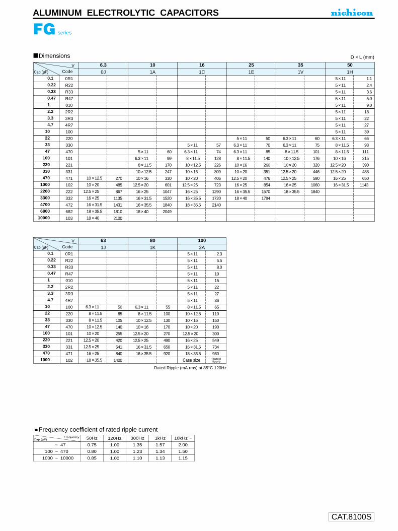
CAT.8100S
ALUMINUM ELECTROLYTIC CAPACITORS
Dimensions
Rated Ripple (mA rms) at 85°C 120Hz
0.1
0.22
0.33
0.47
1
2.2
3.3
4.7
10
22
33
47
100
220
330
470
1000
2200
3300
4700
6800
10000
0R1
R22
R33
R47
010
2R2
3R3
4R7
100
220
330
470
101
221
331
471
102
222
332
472
682
103
0.10 × 12.5
10 × 20
12.5 × 250.
16 × 25
0.16 × 31.5
0.18 × 35.5
18 × 40
270
485
867
1135
1431
1810
2100
V
05 × 11
6.3 × 11.
0.08 × 11.5
0.10 × 12.5
10 × 16
12.5 × 200.
16 × 25
0.16 × 31.5
0.16 × 35.5
18 × 40
60
99
170
247
330
601
1047
1520
1840
2049
05 × 11
6.3 × 11.
0.8 × 11.5
0.10 × 12.5
10 × 16
10 × 20
12.5 × 250.
16 × 25
0.16 × 35.5
0.18 × 35.5
57
74
128
226
309
406
723
1290
1720
2140
05 × 11
6.3 × 11.
6.3 × 11.
0.08 × 11.5
10 × 16
10 × 20
12.5 × 20.0
16 × 25
0.16 × 35.5
18 × 40
50
70
85
140
260
351
476
854
1570
1794
6.3 × 11.
6.3 × 11.
0.8 × 11.5
0.10 × 12.5
10 × 20
12.5 × 200.
12.5 × 250.
16 × 25
0.18 × 35.5
60
75
101
176
320
446
590
1060
1840
05 × 11
05 × 11
05 × 11
05 × 11
05 × 11
05 × 11
05 × 11
05 × 11
05 × 11
6.3 × 11.
0.08 × 11.5
0.08 × 11.5
10 × 16
12.5 × 200.
12.5 × 200.
16 × 25
0.16 × 31.5
1.1
2.4
3.6
5.0
9.0
18
22
27
39
65
93
111
215
390
488
650
1143
50352516106.31H1V1E1C1A0JCodeCap.(µF)
D × L (mm)
0.1
0.22
0.33
0.47
1
2.2
3.3
4.7
10
22
33
47
100
220
330
470
1000
0R1
R22
R33
R47
010
2R2
3R3
4R7
100
220
330
470
101
221
331
471
102
V
6.3 × 11.
0.08 × 11.5
0.08 × 11.5
0.10 × 12.5
10 × 20
12.5 × 200.
12.5 × 250.
16 × 25
0.18 × 35.5
50
85
105
140
255
420
541
840
1400
6.3 × 11.
11.8 × 11.5
0.10 × 12.5
10 × 16
12.5 × 20.0
12.5 × 25.0
.016 × 31.5
.016 × 35.5
055
100
130
170
270
490
650
920
05 × 11
05 × 11
05 × 11
05 × 11
05 × 11
05 × 11
05 × 11
05 × 11
0.08 × 11.5
0.10 × 12.5
10 × 16
10 × 20
12.5 × 200
16 × 25
0.16 × 31.5
0.18 × 35.5
2.3
5.5
8.0
10
15
22
27
36
65
110
150
190
300
549
734
980
10080632A1K1JCodeCap.(µF)
RatedrippleCase size
FG series
Frequency coefficient of rated ripple currentFrequency
Cap.(µF)
~ 47
100 ~ 470
1000 ~ 10000
50Hz
0.75
0.80
0.85
120Hz
1.00
1.00
1.00
300Hz
1.35
1.23
1.10
1kHz
1.57
1.34
1.13
10kHz ~
2.00
1.50
1.15
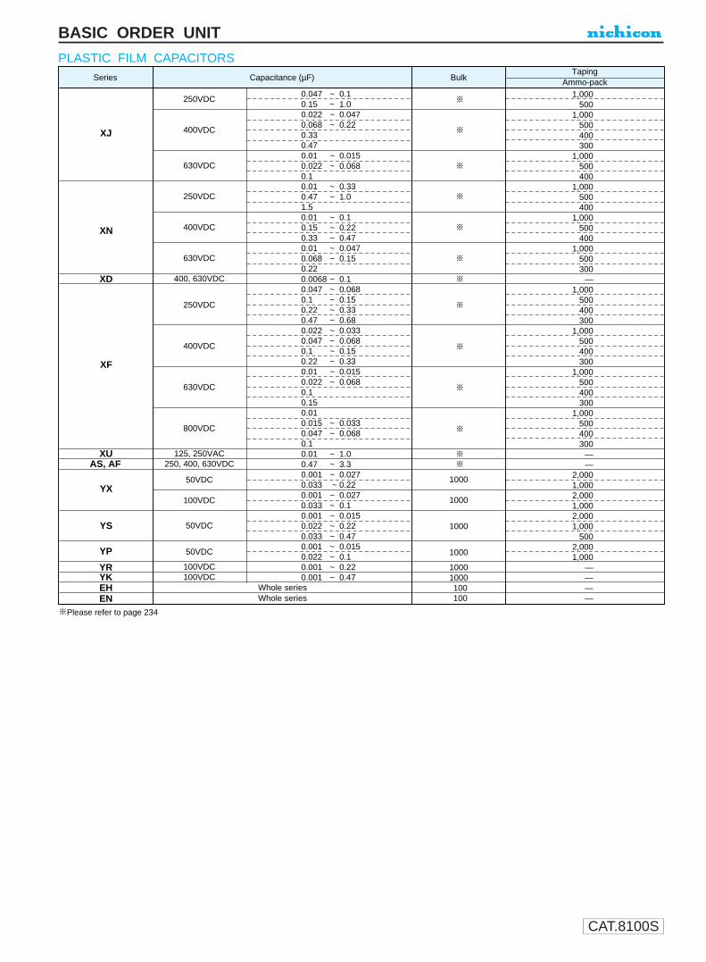
CAT.8100S
BASIC ORDER UNIT
PLASTIC FILM CAPACITORSSeries Capacitance (µF) Bulk
TapingAmmo-pack
XJ
250VDC
400VDC
630VDC
250VDC
400VDC
630VDC
400, 630VDC
250VDC
400VDC
630VDC
800VDC
125, 250VAC250, 400, 630VDC
50VDC
100VDC
50VDC
50VDC
100VDC100VDC
0.047 ~ 0.10.15 ~ 1.00.022 ~ 0.0470.068 ~ 0.220.330.470.01 ~ 0.0150.022 ~ 0.0680.10.01 ~ 0.330.47 ~ 1.01.50.01 ~ 0.10.15 ~ 0.220.33 ~ 0.470.01 ~ 0.0470.068 ~ 0.150.220.0068 ~ 0.10.047 ~ 0.0680.1 ~ 0.150.22 ~ 0.330.47 ~ 0.680.022 ~ 0.0330.047 ~ 0.0680.1 ~ 0.150.22 ~ 0.330.01 ~ 0.0150.022 ~ 0.0680.10.150.010.015 ~ 0.0330.047 ~ 0.0680.10.01 ~ 1.00.47 ~ 3.30.001 ~ 0.0270.033 ~ 0.220.001 ~ 0.0270.033 ~ 0.10.001 ~ 0.0150.022 ~ 0.220.033 ~ 0.470.001 ~ 0.0150.022 ~ 0.10.001 ~ 0.220.001 ~ 0.47
1000
1000
1000
1000
10001000100100
1,000500
1,000500400300
1,000500400
1,000500400
1,000500400
1,000500300
—1,000
500400300
1,000500400300
1,000500400300
1,000500400300
——
2,0001,0002,0001,0002,0001,000
5002,0001,000
————
XN
XD
XF
XUAS, AF
EHEN
YX
YS
YP
Whole seriesWhole series
YRYK
Please refer to page 234

CAT.8100S
PLASTIC FILM CAPACITORS
0.01 103
0.015 153
0.022 223
0.033 333
0.047 473
0.068 683
0.1 104
0.15 154
0.22 224
0.33 334
0.47 474
0.68 684
XF series
250VDC 400VDC 630VDC 800VDC
Style Quantity Case Code Style Quantity Case Code Style Quantity Case Code Style Quantity Case Code
R 1000 3 R 1000 3
500 1
R 1000 3 500 1
4
R 1000 3 500 1 4 400
500 1 400 4 400 300
300
400 4 300
300 4
SizeCase code A
330
330
330
350
NO.1
NO.2
NO.3
NO.4
B
235
300
330
360
C
(mm)
55
55
55
62A±2
C±2
B±2
(µF)Cap.
XJ series
250VDC 400VDC 630VDC
XN series XU series
250VDC 400VDC 600VDC 125VAC 250VAC
Order quantity (Taping)
0.01
0.015
0.022
0.033
0.047
0.068
0.1
0.15
0.22
0.33
0.47
0.68
1.0
1.5
103
153
223
333
473
683
104
154
224
334
474
684
105
155
series
W.V.Item
Code
(µF) Cap. Style Quantity Case Code Style Quantity Case Code Style Quantity Case Code Style Quantity Case Code Style Quantity Case Code Style Quantity Case Code Style Quantity Case Code Style Quantity Case Code
L
M
1000
500
R
E
500
1000
3
2
R
1
500
400
1000
1
4
A
L
M
1
2
3
4
A
E
R
1000
500
400
1
2
E
R
1000
500
300
1
2
4
3
4
3
4
2
1000
500
400
3
4
400
300
2
3
4
E 1
2
3
4
500
400
300
1
2
3
4
3
500
300
R
E
R
1000
1000
series
W.V.Item
Code
Packing Quantity (Ammo-Pack)
XN series XD series XF seriesXJ series
250VDC 400VDC 630VDC 250VDC 400VDC 630VDC250VDC 400VDC 630VDC250VDC 400VDC 630VDC250VDC 400VDC 630VDC 800VDC 125VDC 250VDC400VDC 630VDC
XU series AS series AF series
Order quantity (Bulk)
0.0068
0.01
0.015
0.022
0.033
0.047
0.068
0.1
0.15
0.22
0.33
0.47
0.68
1.0
1.5
2.2
3.3
4.7
6.8
10.0
682
103
153
223
333
473
683
104
154
224
334
474
684
105
155
225
335
475
685
106
series
W.V.Code
(µF) Cap.
1000
800
600
1000
800
600
500
800
600
400
300
1000
800
600
500
1000 1000 1000
800
800
500
1000
1000
800
600
400
300
1000
800
600
500
1000
1000
800
1000
800
600
500
400
300
200
150
1000
800
500
400
300
250
200
125
100
1000
600
500
400
300
200
150
100
1000
800
700
500
300
250
200
400
1000
800
400
600
1000
800
600
500
350
800
600
500
400
250
800
1000
600
500
800
700
500
400
300
200
150
100
1000
800
600
500
350
250
200
125
100
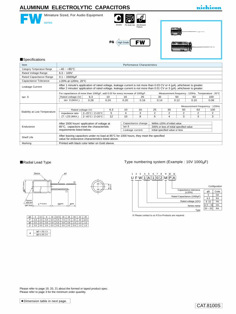
CAT.8100S
ALUMINUM ELECTROLYTIC CAPACITORS
FW series
Miniature Sized, For Audio Equipment
Radial Lead Type Type numbering system (Example : 10V 1000µF)
Specifications
Category Temperature Range
Rated Voltage Range
Rated Capacitance Range
Capacitance Tolerance
Leakage Current
tan δ
Stability at Low Temperature
Endurance
Shelf Life
Marking
Performance CharacteristicsItem
–40 ~ +85°C6.3 ~ 100V0.1 ~ 33000µF
±20% at 120Hz, 20°C
After 1 minute's application of rated voltage, leakage current is not more than 0.03 CV or 4 (µA) ,whichever is greater.After 2 minutes' application of rated voltage, leakage current is not more than 0.01 CV or 3 (µA) ,whichever is greater.
Printed with black color letter on Gold sleeve.
For capacitance of more than 1000µF, add 0.02 for every increase of 1000µF. Measurement frequency : 120Hz, Temperature : 20°C
Measurement frequency : 120Hz
Capacitance change
Leakage current
After 2000 hours' application of voltage at 85°C, capacitors meet the characteristicrequirements listed below.
After leaving capacitors under no load at 85°C for 1000 hours, they meet the specified value for endurance characteristics listed above.
tan δWithin ±20% of initial value200% or less of initial specified valueInitial specified value or less
Rated voltage (V)tan δ (MAX.)
6.30.28
100.24
160.20
250.16
350.14
500.12
630.10
1000.08
Z–25°C / Z+20°C
Z–40°C / Z+20°C
Rated voltage (V)
Impedance ratioZT / Z20 (MAX.)
6.3512
10410
1638
2525
3524
5023
6323
10023
FWFG High Grade
Please refer to page 19, 20, 21 about the formed or taped product spec.Please refer to page 3 for the minimum order quantity.
(φD < 20) 1.5
(φD 20) 2.0
φDP
5
0.5
2.06.3
0.5
2.58
0.5
3.510
0.5
5.012.5
0.5
5.016
0.5
7.518
0.5
7.5φd 0.5 0.5 0.6 0.6 0.6 0.8 0.8
20
0.5
101.0
22
1.0
101.0
25
1.0
12.51.0
Pressurerelief vent
P± 0
.5
L+ MAX 15MIN 4MIN
Sleeve φ d
φD+
0.5
MA
X
(φ6.3up)
U1
F2
W3
14
A5
16
07
28
M9
P10
A11
Configuration
Capacitance tolerance(±20%)
Rated Capacitance (1000µF)
Rated voltage (10V)
Series name
Type
φD
5
Code
DA
6.3
8 ·10
EA
PA
12.5 ~ 18 HA
20 ~ 25 RA
Please contact to us if Eco-Products are required.
Dimension table in next page.

CAT.8100S
ALUMINUM ELECTROLYTIC CAPACITORS
FW series
Frequency coefficient of rated ripple currentFrequency
Cap.(µF)
~ 47
100 ~ 470
1000 ~ 33000
50Hz
0.75
0.80
0.85
120Hz
1.00
1.00
1.00
300Hz
1.35
1.23
1.10
1kHz
1.57
1.34
1.13
10kHz ~
2.00
1.50
1.15
Dimensions
0.1
0.22
0.33
0.47
1
2.2
3.3
4.7
10
22
33
47
100
220
330
470
1000
2200
3300
4700
6800
10000
15000
22000
33000
0R1
R22
R33
R47
010
2R2
3R3
4R7
100
220
330
470
101
221
331
471
102
222
332
472
682
103
153
223
333
6.3 × 11
6.3 × 11
8 × 11.5
10 × 20
10 × 20
12.5 × 20
12.5 × 25
16 × 25
16 × 35.5
18 × 40
22 × 50
265
310
530
980
1170
1350
1600
2000
2550
3200
3900
0J
V 6.3
5 × 11
6.3 × 11
6.3 × 11
6.3 × 11
10 × 12.5
10 × 20
12.5 × 20
12.5 × 25
16 × 25
16 × 35.5
18 × 35.5
20 × 40
22 × 50
145
230
270
330
630
1050
1420
1800
2150
2500
2720
3700
4500
1A
10
5 × 11
6.3 × 11
8 × 11.5
8 × 11.5
10 × 16
12.5 × 20
12.5 × 25
16 × 25
16 × 35.5
18 × 35.5
20 × 40
22 × 50
25 × 50
155
250
360
420
770
1250
1700
2100
2500
2640
3400
4200
4800
1C
16
5 × 11
6.3 × 11
8 × 11.5
10 × 12.5
10 × 12.5
10 × 20
12.5 × 25
16 × 25
16 × 31.5
18 × 35.5
20 × 40
22 × 50
25 × 50
115
185
320
420
530
950
1550
1950
2360
2590
3000
3800
4500
1E
25
5 × 11
5 × 11
6.3 × 11
10 × 12.5
10 × 12.5
10 × 16
12.5 × 20
16 × 25
16 × 35.5
18 × 35.5
20 × 40
22 × 50
25 × 50
105
120
200
370
470
630
1100
1800
2220
2490
3000
3700
4300
1V
35
5 × 11
5 × 11
5 × 11
5 × 11
5 × 11
5 × 11
5 × 11
5 × 11
5 × 11
5 × 11
5 × 11
6.3 × 11
8 × 11.5
10 × 12.5
10 × 16
12.5 × 20
12.5 × 25
16 × 35.5
18 × 35.5
20 × 40
22 × 50
25 × 50
1.1
2.4
3.5
5.0
10
23
35
40
65
95
120
150
250
410
570
760
1300
2090
2360
2900
3500
4000
1H
50
5 × 11
5 × 11
6.3 × 11
6.3 × 11
10 × 12.5
10 × 16
10 × 20
12.5 × 20
16 × 25
18 × 35.5
20 × 40
22 × 50
25 × 50
70
100
140
165
300
470
650
880
1300
2200
2700
3400
3500
1J
63
5 × 11
5 × 11
5 × 11
5 × 11
5 × 11
5 × 11
5 × 11
5 × 11
6.3 × 11
6.3 × 11
8 × 11.5
10 × 12.5
10 × 20
12.5 × 25
12.5 × 25
16 × 25
18 × 40
22 × 50
25 × 50
Case size
2.1
4.7
7.0
10
21
30
40
45
75
120
160
210
350
600
750
1000
1370
2400
2900
100
Code 2A
D × L (mm)
Rated Ripple (mA rms) at 85°C 120Hz
Cap.(µF)
Ratedripple

CAT.8100S
ALUMINUM ELECTROLYTIC CAPACITORS
Miniature sized "nichicon MUSE" acoustic series.Suited for use in audio devices where lighter, thinner, shorterand smaller capacitors are required.
Type numbering system (Example : 10V 330µF)
Specifications
Category Temperature Range
Rated Voltage Range
Rated Capacitance Range
Capacitance Tolerance
Leakage Current
tan δ
Stability at Low Temperature
Endurance
Shelf Life
Marking
Performance CharacteristicsItem
–40 ~ +85°C6.3 ~ 100V
0.1 ~ 22000µF
±20% at 120Hz, 20°C
After 2 minutes' application of rated voltage, leakage current is not more than 0.01CV or 3 (µA ) , whichever is greater.After 1 minute's application of rated voltage, leakage current is not more than 0.03CV or 4 (µA ) , whichever is greater.
Printed with silver color letter on emerald green sleeve.
After 1000 hours' application of rated voltageat 85°C, capacitors meet the characteristicrequirements listed at right.
After leaving capacitors under no load at 85°C for 1000 hours, they meet the specifiedvalue for endurance characteristics listed above.
Rated voltage (V)tan δ (MAX.)
6.30.26
100.22
160.18
250.16
350.14
500.12
630.10
1000.10
FX
Measurement frequency : 120Hz, Temperature : 20°CFor capacitance of more than 1000µF, add 0.02 for every increase of 1000µF.
FX series
Miniature Sized, For Audio Equipment
Measurement frequency : 120Hz
Z–25°C / Z+20°C
Z–40°C / Z+20°C
Rated voltage (V)
Impedance ratioZT / Z20 (MAX.)
6.3410
1038
1626
2524
3523
5023
6323
10023
Capacitance change
Leakage current
tan δWithin ±20% of initial value200% or less of initial specified value
Initial specified value or less
SK, MC
KZ High Grade
Smaller
Please refer to page 19, 20, 21 about the formed or taped product spec.Please refer to page 3 for the minimum order quantity.
φD
P
(L < 20) 1.5(L 20) 2.0
50.52.0
6.30.52.5
80.53.5
100.55.0
12.50.55.0
160.57.5
180.57.5
φd 0.6 0.6 0.6 0.6 0.8 0.8 0.8
2011.010.011.0
(mm)
Pressurerelief vent
P± 0
.5
L+ MAX 15MIN 4MIN
Sleeve φ d
φD+
M
AX
(φ6.3up)
U1
F2
X3
14
A5
36
37
18
M9
P10
J11
Configuration
Capacitance tolerance (±20%)
Rated Capacitance (330µF)
Rated voltage (10V)
Series name
Type
φD
5
Code
DJ
6.3
8 · 10
EJ
PJ
12.5 ~ 18 HJ
20 NJ
Please contact to us if Eco-Products are required.
Radial Lead Type
Dimension table in next page.
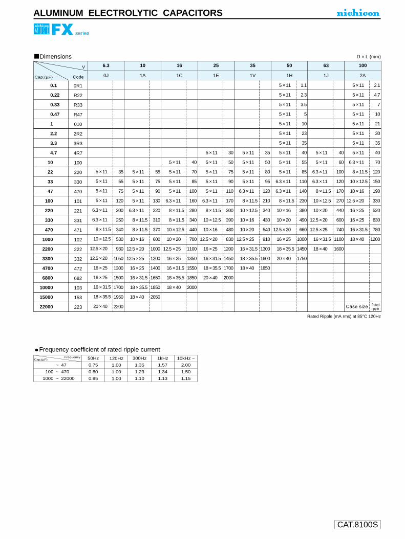
CAT.8100S
ALUMINUM ELECTROLYTIC CAPACITORS
Dimensions
0.1
0.22
0.33
0.47
1
2.2
3.3
4.7
10
22
33
47
100
220
330
470
1000
2200
3300
4700
6800
10000
15000
22000
0R1
R22
R33
R47
010
2R2
3R3
4R7
100
220
330
470
101
221
331
471
102
222
332
472
682
103
153
223
5 × 11
5 × 11
5 × 11
5 × 11
6.3 × 11
6.3 × 11
8 × 11.5
10 × 12.5
12.5 × 20
12.5 × 20
16 × 25
16 × 25
16 × 31.5
18 × 35.5
20 × 40
35
55
75
120
200
250
340
530
930
1050
1300
1500
1700
1950
2200
0J
V 6.3
5 × 11
5 × 11
5 × 11
5 × 11
6.3 × 11
8 × 11.5
8 × 11.5
10 × 16
12.5 × 20
12.5 × 25
16 × 25
16 × 31.5
18 × 35.5
18 × 40
55
75
90
130
220
310
370
600
1000
1200
1400
1650
1850
2050
1A
10
5 × 11
5 × 11
5 × 11
5 × 11
6.3 × 11
8 × 11.5
8 × 11.5
10 × 12.5
10 × 20
12.5 × 25
16 × 25
16 × 31.5
18 × 35.5
18 × 40
40
70
85
100
160
280
340
440
700
1100
1350
1550
1850
2000
1C
16
5 × 11
5 × 11
5 × 11
5 × 11
5 × 11
6.3 × 11
8 × 11.5
10 × 12.5
10 × 16
12.5 × 20
16 × 25
16 × 31.5
18 × 35.5
20 × 40
30
50
75
90
110
170
300
390
480
830
1200
1450
1700
2000
1E
25
5 × 11
5 × 11
5 × 11
5 × 11
6.3 × 11
8 × 11.5
10 × 12.5
10 × 16
10 × 20
12.5 × 25
16 × 31.5
18 × 35.5
18 × 40
35
50
80
95
120
210
340
430
540
910
1300
1600
1850
1V
35
5 × 11
5 × 11
5 × 11
5 × 11
5 × 11
5 × 11
5 × 11
5 × 11
5 × 11
5 × 11
6.3 × 11
6.3 × 11
8 × 11.5
10 × 16
10 × 20
12.5 × 20
16 × 25
18 × 35.5
20 × 40
1.1
2.3
3.5
5
10
23
35
40
55
85
110
140
230
380
490
660
1000
1450
1750
1H
50
5 × 11
5 × 11
6.3 × 11
6.3 × 11
8 × 11.5
10 × 12.5
10 × 20
12.5 × 20
12.5 × 25
16 × 31.5
18 × 40
40
60
100
120
170
270
440
600
740
1100
1600
1J
63
5 × 11
5 × 11
5 × 11
5 × 11
5 × 11
5 × 11
5 × 11
5 × 11
6.3 × 11
8 × 11.5
10 × 12.5
10 × 16
12.5 × 20
16 × 25
16 × 25
16 × 31.5
18 × 40
Case size
2.1
4.7
7
10
21
30
35
40
70
120
150
190
330
520
630
780
1200
100
Code 2A
D × L (mm)
Rated Ripple (mA rms) at 85°C 120Hz
Cap.(µF)
FX series
Frequency coefficient of rated ripple currentFrequency
Cap.(µF)
~ 47
100 ~ 470
1000 ~ 22000
50Hz
0.75
0.80
0.85
120Hz
1.00
1.00
1.00
300Hz
1.35
1.23
1.10
1kHz
1.57
1.34
1.13
10kHz ~
2.00
1.50
1.15
Ratedripple

CAT.8100S
Within ±20% of initial valueCapacitance change
ALUMINUM ELECTROLYTIC CAPACITORS
GJ series
Snap-in Terminal Type, Low-Profile Sized,Wide Temperature Range
Withstanding 3000hours application of ripple current at 105°C.Ideally suited for flat design fo switching power supply.
Drawing Type numbering system (Example : 200V 330µF)
GJ
LowProfile
GU
Category Temperature Range
Rated Voltage Range
Rated Capacitance Range
Capacitance Tolerance
Leakage Current
tan δ
Stability at Low Temperature
Endurance
Shelf Life
Marking
Performance CharacteristicsItem
– 40 ~ +105°C (160 ~ 250V) , – 25 ~ +105°C (315 ~ 400V)
160 ~ 400V
39 ~ 680µF
±20% at 120Hz, 20°C
I (µA) (After 5 minutes' application of rated voltage) [C : Rated Capacitance(µF), V : Voltage(V)]
Printed with white color letter on black sleeve.
0.15 MAX. 120Hz 20°C
Measurement frequency : 120Hz
After an application of DC voltage (in the range of rated DC voltageeven after over-lapping the specified ripple current) for 3000 hoursat 105°C, capacitors meet the characteristic requirements listed atright.
After leaving capacitors under no load at 105°C for 1000hours, they meet the requirements listed at right.
Z—25°C/Z+20°CZ—40°C/Z+20°C
Rated voltage(V)
Impedance ratio ZT/Z20(MAX.)
160 ~ 250312
315 • 4008
Specifications
(Terminal dimensions)
The other terminal is also available upon request.Please refer to page 197 for schematic of terminal dimensions.
(PC board hole dimensions)
L1
G2
J3
24
D5
36
37
18
M9
E10
L11
B12
Configuration
Case dia. code
Capacitance tolerancce (±20%)
Rated Capacitance (330µF)
Rated voltage (200V)
Series name
Type
φD
22
25
30
35
Code
Z
20 Y
A
B
C
10± 0.1
2-2 φ ± 0.1
4.0±
0.5
2.5
1.5
0.8
+0.2-0.1
+0.2
-0.10.8 +0.2
-0.1
Polarity bar
1020±2
φD +1
MAX
.
4.0±0.5Pressure relief vent
Sleeve (P.E.T.)
Pb free lead finishingPb free PET sleeveWithout bottom plate
Sn-Pb lead finishingPVC sleeve contain PbWith bottom plate
EL HL
Configuration
Please contact to us if other configurations are required.
Bottom plate(code HL only)
039047056068082100120150180220270330390470560680
390470560680820101121151181221271331391471561681
20 × 2022 × 2025 × 2025 × 2030 × 2030 × 2035 × 2035 × 20
0.680.810.981.021.251.301.461.51
20 × 2022 × 2025 × 2025 × 2030 × 2030 × 2035 × 2035 × 20
0.620.800.900.951.151.201.361.43
20 × 2022 × 2022 × 2025 × 2030 × 2030 × 2035 × 2035 × 20
0.560.730.800.851.051.101.301.41
20 × 2022 × 2025 × 2025 × 2030 × 2030 × 2035 × 20
0.510.600.740.750.951.001.16
20 × 2022 × 2022 × 2025 × 2030 × 2030 × 2035 × 2035 × 20
20 × 2022 × 2025 × 2025 × 2030 × 2030 × 2035 × 2035 × 20
Case size
0.380.450.470.560.650.700.850.90
0.320.370.400.460.550.600.750.80
Ratedripple
160V (2C) 180V (2Z) 200V (2D) 250V (2E) 315V (2F) 400V (2G) Code
Dimensions D × L (mm)
Rated Ripple (A rms) at 105°C 120Hz
Frequency coefficient of rated ripple currentFrequency (Hz)
160 ~ 250V315 · 400V
Coeff.
50 60 120 300 1 k 10k~ 50k~0.81 0.85 1.00 1.17 1.32 1.45 1.500.77 0.82 1.00 1.16 1.30 1.41 1.43
V(Code)Cap.(µF)
Leakage current
tan δInitial specified value or less
200% or less of initial specified value
Capacitance change
Leakage current
tan δWithin ±15% of initial value
Initial specified value or less
150% or less of initial specified value
Minimum order quantity : 50pcs.
3 CV

CAT.8100S
ALUMINUM ELECTROLYTIC CAPACITORS
GJ(15) series
Snap-in Terminal Type, Low-Profile Sized,Wide Temperature Range.
Withstanding 2000 hours application of ripple current at 105°C.Smaller than low-profile GJ series.Ideally suited for flat design of switching power supply.
GJ(15)
LowProfile
GU
Category Temperature Range
Rated Voltage Range
Rated Capacitance Range
Capacitance Tolerance
Leakage Current
tan δ
Stability at Low Temperature
Endurance
Shelf Life
Marking
Performance CharacteristicsItem
– 40 ~ +105°C (160~250V) , – 25 ~ +105°C (315 ~ 400V)
160 ~ 400V
39 ~ 390µF
±20% at 120Hz, 20°C
I (µA) (After 5 minutes' application of rated voltage) [C : Rated Capacitance(µF), V : Voltage(V)]
Printed with white color letter on black sleeve.
0.20 MAX. 120Hz 20°C
Measurement frequency : 120Hz
After an application of DC voltage (in the range of rated DC voltageeven after over-lapping the specified ripple current) for 2000 hoursat 105°C, capacitors meet the characteristic requirements listed atright.
After leaving capacitors under no load at 105°C for 1000hours, they meet the requirements listed at right.
Z—25°C/Z+20°CZ—40°C/Z+20°C
Rated voltage(V)
Impedance ratio ZT/Z20(MAX.)
160 ~ 250312
315 • 4008—
Specifications
Capacitance change
Leakage current
tan δWithin ±20% of initial value
Initial specified value or less
200% or less of initial specified value
Capacitance change
Leakage current
tan δWithin ±15% of initial value
Initial specified value or less
150% or less of initial specified value
L1
G2
J3
24
D5
36
37
18
M9
E10
L11
C12
113
514
Configuration
Case dia. code
Case length code
Capacitance tolerance (±20%)
Rated Capacitance (330µF)
Rated voltage (200V)
Series name
Type
20
22
25
30
35
Code
Y
Z
A
B
C
φD
(Terminal dimensions) (PC board hole dimensions)
10± 0.1
2-2 φ ± 0.1
4.0±
0.5
2.5
1.5
0.8
+0.2-0.1
+0.2
-0.10.8 +0.2
-0.1
Polarity bar
1015±2
φ D +1
MAX
.
4.0±0.5Pressure relief vent
Sleeve (P.E.T.)
Pb free lead finishingPb free PET sleeve
Sn-Pb lead finishingPVC sleeve contain Pb
EL HL
Configuration
Please contact to us if other configurations are required.
Frequency coefficient of rated ripple currentFrequency (Hz)
160 ~ 250V315 · 400V
Coeff.
50 60 120 300 1 k 10k~ 50k~0.81 0.85 1.00 1.17 1.32 1.45 1.500.77 0.82 1.00 1.16 1.30 1.41 1.43
Minimum order quantity : 50pcs.
Drawing Type numbering system (Example : 200V 330µF)
039047056068082100120150180220270330390
390470560680820101121151181221271331391
20 × 1522 × 1525 × 1530 × 1530 × 1535 × 15
0.550.650.800.951.001.20
20 × 1522 × 1525 × 1530 × 1530 × 1535 × 1535 × 15
0.500.600.750.851.001.101.20
20 × 1522 × 1525 × 1525 × 1530 × 1530 × 1535 × 15
0.450.550.650.750.901.001.10
22 × 1525 × 1530 × 1530 × 1535 × 1535 × 15
0.500.600.700.750.901.00
22 × 1525 × 1530 × 1530 × 1535 × 1535 × 15
22 × 1525 × 1530 × 1530 × 1535 × 1535 × 15
Case size
0.350.400.450.500.550.60
0.300.350.400.450.500.55
Ratedripple
160V (2C) 180V (2Z) 200V (2D) 250V (2E) 315V (2F) 400V (2G) Code
Dimensions D × L (mm)
Rated Ripple (A rms) at 105°C 120Hz
V(Code)Cap.(µF)
3 CV

CAT.8100S
L± 2
6.3± 1
φD+1
MA
X.
4 -φ2 ± 0.1
22.5± 0.1
25.0 ± 0.1
L± 2
6.3± 1
φD+1
MA
X.
5 -φ2± 0.1
L1
G2
K3
24
D5
26
77
28
M9
E10
H11
D12
Configuration
Case dia. code
Capacitance tolerance (± 20%)
Rated Capacitance (2700µF)
Rated voltage (200V)
Series name
Type
φD
35
40
Code
C
D
Notes:As blank terminals are not insulated from capacitor element,they shall be mounted on independent lands.
BLANK
Pressure relief vent
Pressure relief vent
BLANK
30°30°
BLANKBLANK
30°30°
30°
CD
B
BLANK
A
A
(PC board hole dimensions)
(PC board hole dimensions)
CB
Sleeve (P.E.T.)
Sleeve (P.E.T.)
Bottom plate(code HH only)
Bottom plate(code HH only)
ConfigurationPb free lead finishingPb free PET sleeveWithout bottom plate
Sn-Pb lead finishingPVC sleeve contain PbWith bottom plate
EH HH Please contact to us if other configurations are required.
ALUMINUM ELECTROLYTIC CAPACITORS
GKHH series
PC Board Mounting Type
Higher C/V products.Plentiful line-up from φ35 × 63 to φ40 × 100mm.Auxiliary terminals provided to assure anti-vibration performamance.
Drawing
Specifications
Type numbering system (Example : 200V 2700µF)
Category Temperature Range
Rated Voltage Range
Rated Capacitance Range
Capacitance Tolerance
Leakage Current
tan δ
Stability at Low Temperature
Endurance
Shelf Life
Marking
Performance CharacteristicsItem
– 40 ~ +105°C (16 ~ 250V) , – 25 ~ +105°C (400V)
16 ~ 400V
560 ~ 68000µF
±20% at 120Hz, 20°C
I (µA) (After 5 minutes' application of rated voltage) [C : Capacitance(µF) , V : Voltage(V)]
Printed with white color letter on black sleeve.
Measurement frequency : 120Hz, Temperature : 20°C
Measurement frequency : 120Hz
After an application of DC voltage(in the range of ratedDC voltage even after over-lapping the specified ripplecurrent) for 2000 hours at 105°C, capacitors meetthe characteristic requirements listed at right.
After leaving capacitors under no load at 105°C for 1000 hours, they meet the requirements listed at right.
Rated voltage(V)
tan δ (MAX.)16
0.6025
0.5035
0.4050
0.3563
0.3080
0.301000.25
1600.20
2000.15
2500.15
4000.30
Z–25°C/Z+20°C
Z–40°C/Z+20°C
Rated voltage(V)
Impedance ratioZT/Z20 (MAX.)
16 ~ 2504
15
4008—
For all of φ35mm products and for 63mmL or shorter with φ40mm.
For 63mmL or longer with φ40mm.
Frequency coefficient of rated ripple current
Dimension table in next page.
25.0 ± 0.1
L± 2
6.3± 1
φD+1
MA
X.
5 -φ2± 0.1
Pressure relief vent
BLANKBLANK
30°30°
30°
CD
B
BLANKA
(PC board hole dimensions) Sleeve (P.E.T.) Bottom plate(code HH only)
Frequency (Hz)016 ~ 100V160 ~ 250V
400VCoeff.
50 60 120 1 k 10k~0.88 0.90 1.00 1.15 1.150.85 0.88 1.00 1.15 1.200.88 0.90 1.00 1.10 1.15
Capacitance change
Leakage current
tan δWithin ±20% of initial value
Initial specified value or less
200% or less of initial specified value
Capacitance change
Leakage current
tan δWithin ±15% of initial value
Initial specified value or less
150% or less of initial specified value
3 CV
Minimum order quantity : 50pcs.
(Through 100V only)

CAT.8100S
Dimensions
GKHH series
ALUMINUM ELECTROLYTIC CAPACITORS
Rated Ripple (A rms) at 105°C 120Hz
D × L (mm)
18000
22000
27000
33000
39000
47000
56000
68000
183
223
273
333
393
473
563
683
35 × 635.90
35 × 686.20
35 × 806.90
40 × 505.75
40 × 636.45
40 × 636.70
35 4016V (1C) V(Code)
Code
35 × 635.60
35 × 686.00
35 × 806.80
40 × 505.50
40 × 636.30
40 × 636.60
35 4025V (1E)
35 × 635.10
35 × 685.50
35 × 806.25
40 × 505.00
40 × 635.80
40 × 636.05
35 4035V (1V)
35 × 685.55
35 × 806.35
40 × 635.80
40 × 636.15
35 4050V (1H)
560
680
820
1000
1200
1500
1800
2200
2700
3300
3900
4700
561
681
821
102
122
152
182
222
272
332
392
472
35 × 633.50
35 × 683.90
35 × 804.55
35 × 1005.30
40 × 503.45
40 × 634.10
40 × 634.40
40 × 805.20
40 × 1006.15
35 40160V (2C) V(Code)
35 × 633.30
35 × 803.90
35 × 1004.65
40 × 503.20
40 × 633.80
40 × 804.50
40 × 804.90
40 × 1005.70
35 40200V (2D)
35 × 632.75
35 × 683.20
35 × 1004.05
35 × 1004.35
40 × 502.70
40 × 633.35
40 × 803.95
40 × 804.20
40 × 1005.00
35 40250V (2E)
35 × 631.75
35 × 802.05
35 × 802.20
35 × 1002.65
40 × 501.70
40 × 632.00
40 × 802.60
40 × 1003.00
35 40400V (2G)
5600
6800
8200
10000
12000
15000
562
682
822
103
123
153
35 × 635.35
35 × 685.85
40 × 505.25
40 × 636.10
35 4063V (1J) V(Code)
35 × 634.75
35 × 805.45
40 × 504.65
40 × 635.00
35 4080V (1K)
35 × 684.40
35 × 804.80
40 × 634.55
40 × 634.65
35 40100V (2A)
Case size
Rated ripple
φD
φDCodeCap.(µF)
φDCodeCap.(µF)
Cap.(µF)

CAT.8100S
160 ~ 250
4
ALUMINUM ELECTROLYTIC CAPACITORS
GN series
Snap-in Terminal Type, Smaller-Sized, Wide Temperature Range
Withstanding 2000 hours application of ripple current at 105°C.One rank smaller case sized than GU series.
Specifications
Type numbering system (Example : 400V 180µF)
Category Temperature Range
Rated Voltage Range
Rated Capacitance Range
Capacitance Tolerance
Leakage Current
tan δ
Stability at Low Temperature
Endurance
Shelf Life
Marking
Performance CharacteristicsItem
– 40 ~ +105°C (160 ~ 250V) , – 25 ~ +105°C (350 ~ 450V)
160 ~ 450V
56 ~ 3300µF
±20% at 120Hz, 20°C
I (µA) (After 5 minutes' application of rated voltage) [C : Rated Capacitance(µF), V : Voltage(V)]
Printed with white color letter on black sleeve.
Measurement frequency : 120Hz
Temperature : 20°CZ—25°C/Z+20°C
Rated voltage (V)
Impedance ratioZT/Z20 (MAX.)
350 ~ 450
8
Dimension table in next page.
Drawing
Smaller
L1
G2
N3
24
G5
16
87
18
M9 10
E13
L11 14
A12
3 0
Configuration
Case dia. code
Case length code
Capacitance tolerance (± 20%)
Rated Capacitance (180µF)
Rated voltage (400V)
Series name
Type
φD
222530
Code
Z20 Y
AB
35 C
Pb free lead finishingPb free PET sleeve
Sn-Pb lead finishingPVC sleeve contain Pb
EL HL
Configuration
Please contact to us if other configurations are required.
10± 0.1
2-2φ± 0.1
(Terminal dimensions)
The other terminal is also available upon request.Please refer page 197 for schematic of dimensions.
(PC board hole dimensions)
4.0±
0.5
2.5
1.5
0.8
+0.2-0.1
+0.2-0.1
0.8+0.2-0.1
Polarity bar
10L± 2
φD +1
MAX
.
4.0± 0.5Pressure relief vent
Sleeve (P.E.T.)
GN
GU
3 CV
Minimum order quantity : 50pcs.
After an application of DC voltage(in the range of rated DCvoltage even after over-lapping the specified ripple current) for2000 hours at 105°C, capacitors meet the characteristicrequirements listed at right.
After leaving capacitors under no load at 105°C for 1000hours, they meet the characteristic requirements listed at right.
Capacitance change
Leakage current
tan δWithin ±20% of initial value
Initial specified value or less
200% or less of initial specified value
Capacitance change
Leakage current
tan δWithin ±20% of initial value
Initial specified value or less
200% or less of initial specified value
Measurement frequency : 120Hz, Temperature : 20°CRated voltage (V)
tan δ (MAX.)160 ~ 420
0.154500.20
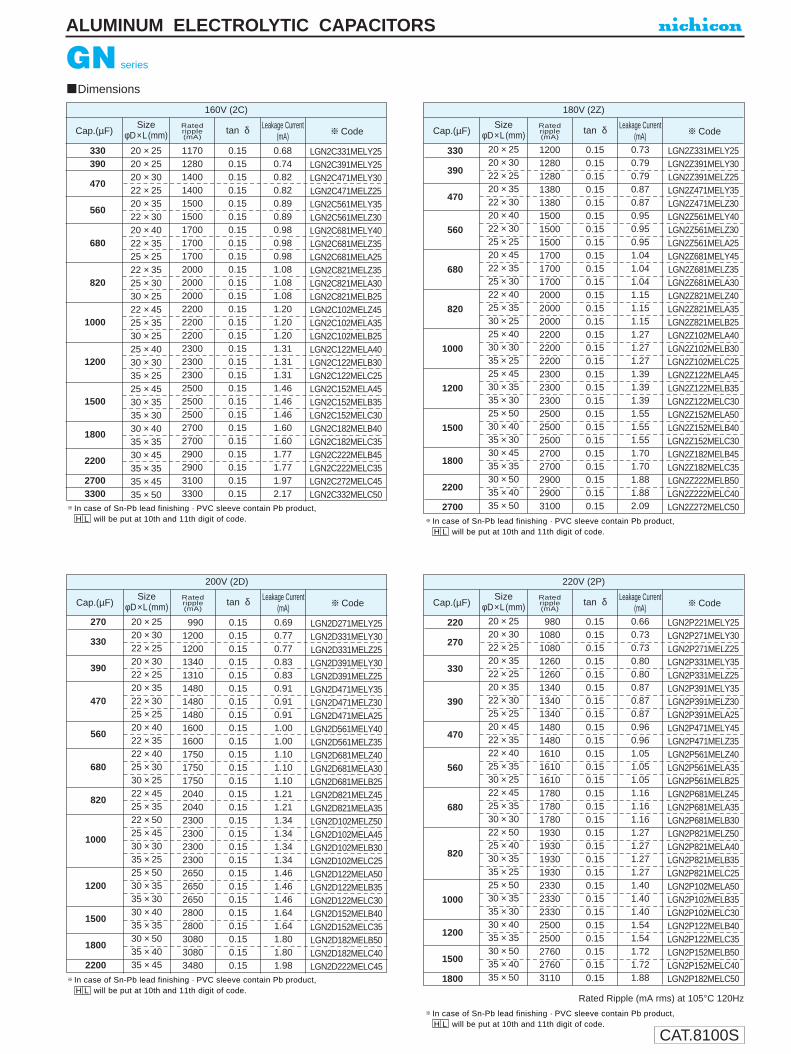
CAT.8100S
Dimensions
330390
470
560
680
820
1000
1200
1500
1800
2200
27003300
20 × 2520 × 2520 × 3022 × 2520 × 3522 × 3020 × 4022 × 3525 × 2522 × 3525 × 3030 × 2522 × 4525 × 3530 × 2525 × 4030 × 3035 × 2525 × 4530 × 3535 × 3030 × 4035 × 3530 × 4535 × 3535 × 4535 × 50
117012801400140015001500170017001700200020002000220022002200230023002300250025002500270027002900290031003300
0.150.150.150.150.150.150.150.150.150.150.150.150.150.150.150.150.150.150.150.150.150.150.150.150.150.150.15
0.680.740.820.820.890.890.980.980.981.081.081.081.201.201.201.311.311.311.461.461.461.601.601.771.771.972.17
LGN2C331MELY25LGN2C391MELY25LGN2C471MELY30LGN2C471MELZ25LGN2C561MELY35LGN2C561MELZ30LGN2C681MELY40LGN2C681MELZ35LGN2C681MELA25LGN2C821MELZ35LGN2C821MELA30LGN2C821MELB25LGN2C102MELZ45LGN2C102MELA35LGN2C102MELB25LGN2C122MELA40LGN2C122MELB30LGN2C122MELC25LGN2C152MELA45LGN2C152MELB35LGN2C152MELC30LGN2C182MELB40LGN2C182MELC35LGN2C222MELB45LGN2C222MELC35LGN2C272MELC45LGN2C332MELC50
160V (2C)
Ratedripple(mA)
tan δ Leakage Current(mA) Code
SizeφD×L(mm)Cap.(µF)
330
390
470
560
680
820
1000
1200
1500
1800
2200
2700
20 × 2520 × 3022 × 2520 × 3522 × 3020 × 4022 × 3025 × 2520 × 4522 × 3525 × 3022 × 4025 × 3530 × 2525 × 4030 × 3035 × 2525 × 4530 × 3535 × 3025 × 5030 × 4035 × 3030 × 4535 × 3530 × 5035 × 4035 × 50
1200128012801380138015001500150017001700170020002000200022002200220023002300230025002500250027002700290029003100
0.150.150.150.150.150.150.150.150.150.150.150.150.150.150.150.150.150.150.150.150.150.150.150.150.150.150.150.15
0.730.790.790.870.870.950.950.951.041.041.041.151.151.151.271.271.271.391.391.391.551.551.551.701.701.881.882.09
LGN2Z331MELY25LGN2Z391MELY30LGN2Z391MELZ25LGN2Z471MELY35LGN2Z471MELZ30LGN2Z561MELY40LGN2Z561MELZ30LGN2Z561MELA25LGN2Z681MELY45LGN2Z681MELZ35LGN2Z681MELA30LGN2Z821MELZ40LGN2Z821MELA35LGN2Z821MELB25LGN2Z102MELA40LGN2Z102MELB30LGN2Z102MELC25LGN2Z122MELA45LGN2Z122MELB35LGN2Z122MELC30LGN2Z152MELA50LGN2Z152MELB40LGN2Z152MELC30LGN2Z182MELB45LGN2Z182MELC35LGN2Z222MELB50LGN2Z222MELC40LGN2Z272MELC50
180V (2Z)
Ratedripple(mA)
tan δ Leakage Current(mA) Code
SizeφD×L(mm)Cap.(µF)
220
270
330
390
470
560
680
820
1000
1200
1500
1800
20 × 2520 × 3022 × 2520 × 3522 × 2520 × 3522 × 3025 × 2520 × 4522 × 3522 × 4025 × 3530 × 2522 × 4525 × 3530 × 3022 × 5025 × 4030 × 3535 × 2525 × 5030 × 3535 × 3030 × 4035 × 3530 × 5035 × 4035 × 50
980108010801260126013401340134014801480161016101610178017801780193019301930193023302330233025002500276027603110
0.150.150.150.150.150.150.150.150.150.150.150.150.150.150.150.150.150.150.150.150.150.150.150.150.150.150.150.15
0.660.730.730.800.800.870.870.870.960.961.051.051.051.161.161.161.271.271.271.271.401.401.401.541.541.721.721.88
LGN2P221MELY25LGN2P271MELY30LGN2P271MELZ25LGN2P331MELY35LGN2P331MELZ25LGN2P391MELY35LGN2P391MELZ30LGN2P391MELA25LGN2P471MELY45LGN2P471MELZ35LGN2P561MELZ40LGN2P561MELA35LGN2P561MELB25LGN2P681MELZ45LGN2P681MELA35LGN2P681MELB30LGN2P821MELZ50LGN2P821MELA40LGN2P821MELB35LGN2P821MELC25LGN2P102MELA50LGN2P102MELB35LGN2P102MELC30LGN2P122MELB40LGN2P122MELC35LGN2P152MELB50LGN2P152MELC40LGN2P182MELC50
220V (2P)
Ratedripple(mA)
tan δ Leakage Current(mA) Code
SizeφD×L(mm)Cap.(µF)
270
330
390
470
560
680
820
1000
1200
1500
1800
2200
20 × 2520 × 3022 × 2520 × 3022 × 2520 × 3522 × 3025 × 2520 × 4022 × 3522 × 4025 × 3030 × 2522 × 4525 × 3522 × 5025 × 4530 × 3035 × 2525 × 5030 × 3535 × 3030 × 4035 × 3530 × 5035 × 4035 × 45
99012001200134013101480148014801600160017501750175020402040230023002300230026502650265028002800308030803480
0.150.150.150.150.150.150.150.150.150.150.150.150.150.150.150.150.150.150.150.150.150.150.150.150.150.150.15
0.690.770.770.830.830.910.910.911.001.001.101.101.101.211.211.341.341.341.341.461.461.461.641.641.801.801.98
LGN2D271MELY25LGN2D331MELY30LGN2D331MELZ25LGN2D391MELY30LGN2D391MELZ25LGN2D471MELY35LGN2D471MELZ30LGN2D471MELA25LGN2D561MELY40LGN2D561MELZ35LGN2D681MELZ40LGN2D681MELA30LGN2D681MELB25LGN2D821MELZ45LGN2D821MELA35LGN2D102MELZ50LGN2D102MELA45LGN2D102MELB30LGN2D102MELC25LGN2D122MELA50LGN2D122MELB35LGN2D122MELC30LGN2D152MELB40LGN2D152MELC35LGN2D182MELB50LGN2D182MELC40LGN2D222MELC45
200V (2D)
Ratedripple(mA)
tan δ Leakage Current(mA) Code
SizeφD×L(mm)Cap.(µF)
Rated Ripple (mA rms) at 105°C 120Hz
ALUMINUM ELECTROLYTIC CAPACITORS
GN series
In case of Sn-Pb lead finishing · PVC sleeve contain Pb product,H L will be put at 10th and 11th digit of code.
In case of Sn-Pb lead finishing · PVC sleeve contain Pb product,H L will be put at 10th and 11th digit of code.
In case of Sn-Pb lead finishing · PVC sleeve contain Pb product,H L will be put at 10th and 11th digit of code.
In case of Sn-Pb lead finishing · PVC sleeve contain Pb product,H L will be put at 10th and 11th digit of code.
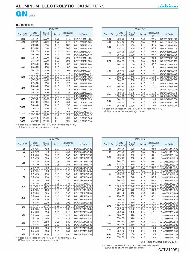
CAT.8100S
GN series
ALUMINUM ELECTROLYTIC CAPACITORS
220270
330
390
470
560
680
820
1000
1200
15001800
22 × 2522 × 2520 × 3522 × 3025 × 2520 × 4022 × 3525 × 3022 × 4025 × 3530 × 2522 × 4525 × 3530 × 3022 × 5025 × 4030 × 3035 × 2525 × 4530 × 3535 × 3030 × 4035 × 3530 × 4535 × 4035 × 4535 × 50
100011001200120012001300130013001400140014001500150015001700170017001700200020002000220022002300230025002700
0.150.150.150.150.150.150.150.150.150.150.150.150.150.150.150.150.150.150.150.150.150.150.150.150.150.150.15
0.700.770.860.860.860.930.930.931.021.021.021.121.121.121.231.231.231.231.351.351.351.501.501.641.641.832.01
LGN2E221MELZ25LGN2E271MELZ25LGN2E331MELY35LGN2E331MELZ30LGN2E331MELA25LGN2E391MELY40LGN2E391MELZ35LGN2E391MELA30LGN2E471MELZ40LGN2E471MELA35LGN2E471MELB25LGN2E561MELZ45LGN2E561MELA35LGN2E561MELB30LGN2E681MELZ50LGN2E681MELA40LGN2E681MELB30LGN2E681MELC25LGN2E821MELA45LGN2E821MELB35LGN2E821MELC30LGN2E102MELB40LGN2E102MELC35LGN2E122MELB45LGN2E122MELC40LGN2E152MELC45LGN2E182MELC50
250V (2E)
Ratedripple(mA)
tan δ Leakage Current(mA) Code
SizeφD×L(mm)Cap.(µF)
6882
100
120
150
180
220
270
330
390
470
560
680
20 × 2520 × 3020 × 3022 × 2520 × 3522 × 3020 × 4022 × 3522 × 3525 × 3030 × 2522 × 4525 × 3530 × 2522 × 5025 × 4030 × 3035 × 2525 × 4530 × 3525 × 5030 × 4035 × 3030 × 4535 × 3530 × 5035 × 4035 × 45
490640680680730730850850950950950
11001100110012201220122012201440144015501550155016801680190019002120
0.150.150.150.150.150.150.150.150.150.150.150.150.150.150.150.150.150.150.150.150.150.150.150.150.150.150.150.15
0.490.540.600.600.650.650.730.730.800.800.800.880.880.880.980.980.980.981.081.081.181.181.181.301.301.411.411.56
LGN2G680MELY25LGN2G820MELY30LGN2G101MELY30LGN2G101MELZ25LGN2G121MELY35LGN2G121MELZ30LGN2G151MELY40LGN2G151MELZ35LGN2G181MELZ35LGN2G181MELA30LGN2G181MELB25LGN2G221MELZ45LGN2G221MELA35LGN2G221MELB25LGN2G271MELZ50LGN2G271MELA40LGN2G271MELB30LGN2G271MELC25LGN2G331MELA45LGN2G331MELB35LGN2G391MELA50LGN2G391MELB40LGN2G391MELC30LGN2G471MELB45LGN2G471MELC35LGN2G561MELB50LGN2G561MELC40LGN2G681MELC45
400V (2G)
Ratedripple(mA)
tan δ Leakage Current(mA) Code
SizeφD×L(mm)Cap.(µF)
Rated Ripple (mA rms) at 105°C 120Hz
120150
180
220
270
330
390
470
560
680
820
22 × 2522 × 3022 × 3025 × 2522 × 3525 × 3022 × 4025 × 3530 × 2522 × 4525 × 4030 × 3025 × 4530 × 3525 × 5030 × 4035 × 3030 × 4535 × 3530 × 5035 × 4035 × 45
750820900900
100010001100110011001200120012001300130014001400140015001500170017001900
0.150.150.150.150.150.150.150.150.150.150.150.150.150.150.150.150.150.150.150.150.150.15
0.610.680.750.750.830.830.920.920.921.011.011.011.101.101.211.211.211.321.321.461.461.60
LGN2V121MELZ25LGN2V151MELZ30LGN2V181MELZ30LGN2V181MELA25LGN2V221MELZ35LGN2V221MELA30LGN2V271MELZ40LGN2V271MELA35LGN2V271MELB25LGN2V331MELZ45LGN2V331MELA40LGN2V331MELB30LGN2V391MELA45LGN2V391MELB35LGN2V471MELA50LGN2V471MELB40LGN2V471MELC30LGN2V561MELB45LGN2V561MELC35LGN2V681MELB50LGN2V561MELC40LGN2V821MELC45
350V (2V)
Ratedripple(mA)
tan δ Leakage Current(mA) Code
SizeφD×L(mm)Cap.(µF)
6882
100
120
150
180
220
270
330
390
470
560680
20 × 2520 × 2520 × 3022 × 2520 × 3522 × 3025 × 2520 × 4022 × 3525 × 3020 × 4522 × 4025 × 3030 × 2522 × 4525 × 3530 × 3025 × 4030 × 3035 × 2525 × 5030 × 3535 × 3030 × 4035 × 3530 × 4535 × 4035 × 4535 × 50
500640660660810810810840840840910910910910
105010501050125012501250142014201420161016101860186021002200
0.150.150.150.150.150.150.150.150.150.150.150.150.150.150.150.150.150.150.150.150.150.150.150.150.150.150.150.150.15
0.500.550.610.610.670.670.670.750.750.750.820.820.820.820.910.910.911.011.011.011.111.111.111.211.211.331.331.451.60
LGNW6680MELY25LGNW6820MELY25LGNW6101MELY30LGNW6101MELZ25LGNW6121MELY35LGNW6121MELZ30LGNW6121MELA25LGNW6151MELY40LGNW6151MELZ35LGNW6151MELA30LGNW6181MELY45LGNW6181MELZ40LGNW6181MELA30LGNW6181MELB25LGNW6221MELZ45LGNW6221MELA35LGNW6221MELB30LGNW6271MELA40LGNW6271MELB30LGNW6271MELC25LGNW6331MELA50LGNW6331MELB35LGNW6331MELC30LGNW6391MELB40LGNW6391MELC35LGNW6471MELB45LGNW6471MELC40LGNW6561MELC45LGNW6681MELC50
420V (W6)
Ratedripple(mA)
tan δ Leakage Current(mA) Code
SizeφD×L(mm)Cap.(µF)
Dimensions
In case of Sn-Pb lead finishing · PVC sleeve contain Pb product,H L will be put at 10th and 11th digit of code.
In case of Sn-Pb lead finishing · PVC sleeve contain Pb product,H L will be put at 10th and 11th digit of code.
In case of Sn-Pb lead finishing · PVC sleeve contain Pb product,H L will be put at 10th and 11th digit of code.
In case of Sn-Pb lead finishing · PVC sleeve contain Pb product,H L will be put at 10th and 11th digit of code.

CAT.8100S
5668
82
100
120
150
180
220
270
330
390
470560
20 × 2520 × 2520 × 3022 × 2520 × 3522 × 3025 × 2522 × 3525 × 3020 × 4522 × 4025 × 3030 × 2522 × 4525 × 3530 × 3025 × 4030 × 3035 × 2525 × 5030 × 3535 × 3030 × 4035 × 3530 × 5035 × 4035 × 4535 × 50
440500640640690690690720720790790790790870870870
105010501050123012301230138013801610161017801990
0.200.200.200.200.200.200.200.200.200.200.200.200.200.200.200.200.200.200.200.200.200.200.200.200.200.200.200.20
0.470.520.570.570.630.630.630.690.690.770.770.770.770.850.850.850.940.940.941.041.041.041.151.151.251.251.371.50
LGN2W560MELY25LGN2W680MELY25LGN2W820MELY30LGN2W820MELZ25LGN2W101MELY35LGN2W101MELZ30LGN2W101MELA25LGN2W121MELZ35LGN2W121MELA30LGN2W151MELY45LGN2W151MELZ40LGN2W151MELA30LGN2W151MELB25LGN2W181MELZ45LGN2W181MELA35LGN2W181MELB30LGN2W221MELA40LGN2W221MELB30LGN2W221MELC25LGN2W271MELA50LGN2W271MELB35LGN2W271MELC30LGN2W331MELB40LGN2W331MELC35LGN2W391MELB50LGN2W391MELC40LGN2W471MELC45LGN2W561MELC50
450V (2W)
Ratedripple(mA)
tan δ Leakage Current(mA) Code
SizeφD×L(mm)Cap.(µF)
Frequency coefficient of rated ripple current
Frequency (Hz) 160~250V350~450Vco
eff
50 60 120 300 1k 10k 50k~0.81 0.85 1.00 1.17 1.32 1.45 1.500.77 0.82 1.00 1.16 1.30 1.41 1.43
ALUMINUM ELECTROLYTIC CAPACITORS
Dimensions
GN series
Rated Ripple (mA rms) at 105°C 120Hz
In case of Sn-Pb lead finishing · PVC sleeve contain Pb product,H L will be put at 10th and 11th digit of code.

CAT.8100S
ALUMINUM ELECTROLYTIC CAPACITORS
GU series
Snap-in Terminal Type, Wide Temperature Range
Withstanding 3000 hours application of ripple current at 105°C.
Specifications
Type numbering system (Example : 200V 680µF)
Category Temperature Range
Rated Voltage Range
Rated Capacitance Range
Capacitance Tolerance
Leakage Current
tan δ
Stability at Low Temperature
Endurance
Shelf Life
Marking
Performance CharacteristicsItem
– 40 ~ + 105°C (16 ~ 250V) , – 25 ~ +105°C (315 ~ 450V)
16 ~ 450V
47~ 47000µF
±20% at 120Hz, 20°C
I (µA) (After 5 minutes' application of rated voltage) [C : Rated Capacitance (µF), V : Voltage (V)]
Printed with white color letter on black sleeve.
Measurement frequency : 120Hz, Temperature : 20°C
Measurement frequency : 120Hz
After an application of DC voltage(in the range of rated DCvoltage even after over-lapping the specified ripple current) for3000 hours at 105°C, capacitors meet the characteristicrequirements listed at right.
After leaving capacitors under no load at 105°C for 1000hours, they meet the characteristic requirements listed at right.
Z—25°C/Z+20°C
Z—40°C/Z+20°C
Rated voltage (V)
Impedance ratioZT/Z20 (MAX.)
160~250312
315~4508—
Dimension table in next page.
Drawing
Smaller
L1
G2
U3
24
D5
66
87
18
M9
E10
L11
A12
Configuration
Case dia. code
Capacitance tolerance (±20%)
Rated Capacitance (680µF)
Rated voltage (200V)
Series name
Type
φD20222530
CodeYZAB
35 C
Pb free lead finishingPb free PET sleeveWithout bottom plate
Sn-Pb lead finishingPVC sleeve contain PbWith bottom plate
EL HL
Configuration
Please contact to us if other configurations are required.
10± 0.1
2-2φ±0.1
(Terminal dimensions)
The other terminal is also available upon request.Please refer page 197 for schematic of dimensions.
(PC board hole dimensions)
4.0±
0.5
2.5
1.5
0.8
+0.2-0.1
+0.2-0.1
0.8+0.2-0.1
Polarity bar
10L±2
φD +1
MAX
.
4.0±0.5Pressure relief vent
Sleeve (P.E.T.)
Bottom plate(code HL only)
GU
GN
Frequency coefficient of rated ripple currentFrequency (Hz)
160~250V315~450V
Coeff.
50 60 120 300 1k 10k 50k~
0.81 0.85 1.00 1.17 1.32 1.45 1.500.77 0.82 1.00 1.16 1.30 1.41 1.43
Capacitance change
Leakage current
tan δWithin ±20% of initial value
Initial specified value or less
200% or less of initial specified value
Capacitance change
Leakage current
tan δWithin ±15% of initial value
Initial specified value or less
150% or less of initial specified value
3 CV
GJ Low Profile
Approved by Reliability Center for Electronic Component, Japan-Certification No. RCJ-03-24D
Minimum order quantity : 50pcs.
16~100420
0.88 0.90 1.00 1.07 1.15 1.15 1.1516~100V
Rated voltage(V)
tan δ (MAX.)16
0.5025
0.4035
0.3550
0.3063
0.2580 • 1000.20
160~4200.15
4500.20
(160V~)

CAT.8100S
ALUMINUM ELECTROLYTIC CAPACITORS
GU series
Dimensions
47005600
6800
8200
10000
12000
15000
18000
22000
2700033000
22×2522×3022×3025×2522×3525×3030×2522×4025×3530×3022×4525×4030×3025×4530×3535×3025×5030×4035×3530×4535×3535×4535×50
16101800191019102140234022502650261026102690281027403270313032603540356038404240396047505500
0.400.400.400.400.400.400.400.400.400.400.400.400.400.400.400.400.400.400.400.400.400.400.40
1.021.121.231.231.351.351.351.501.501.501.641.641.641.831.831.832.012.012.012.222.222.462.72
LGU1E472MELZLGU1E562MELZLGU1E682MELZLGU1E682MELALGU1E822MELZLGU1E822MELALGU1E822MELBLGU1E103MELZLGU1E103MELALGU1E103MELBLGU1E123MELZLGU1E123MELALGU1E123MELBLGU1E153MELALGU1E153MELBLGU1E153MELCLGU1E183MELALGU1E183MELBLGU1E183MELCLGU1E223MELBLGU1E223MELCLGU1E273MELCLGU1E333MELC
25V (1E)
Ratedripple(mA)
tan δLeakageCurrent(mA)
CodeSize
φD×L(mm)Cap.(µF)
1800
2700
3300
3900
4700
5600
6800
8200
10000
1200015000
22×2522×3025×2522×3525×3022×4025×3030×2522×4525×3530×3022×5025×4030×3025×4530×3535×3030×4035×3530×5035×4035×4535×50
13401700170019802000225022802220256026102580289028102950337033903310371036604090407045604770
0.300.300.300.300.300.300.300.300.300.300.300.300.300.300.300.300.300.300.300.300.300.300.30
0.901.101.101.211.211.321.321.321.451.451.451.581.581.581.741.741.741.921.922.122.122.322.59
LGU1H182MELZLGU1H272MELZLGU1H272MELALGU1H332MELZLGU1H332MELALGU1H392MELZLGU1H392MELALGU1H392MELBLGU1H472MELZLGU1H472MELALGU1H472MELBLGU1H562MELZLGU1H562MELALGU1H562MELBLGU1H682MELALGU1H682MELBLGU1H682MELCLGU1H822MELBLGU1H822MELCLGU1H103MELBLGU1H103MELCLGU1H123MELCLGU1H153MELC
50V (1H) Ratedripple(mA)
tan δLeakageCurrent(mA)
CodeSize
φD×L(mm)Cap.(µF)
68008200
10000
12000
15000
18000
22000
27000
33000
39000
47000
22×2522×3022×3025×2522×3525×3030×2522×4025×3530×3022×4525×4030×3025×4530×3535×3025×5030×4035×3030×4535×3530×5035×4035×45
175020002100205023102300238026802680257029803160300034003390325038503830374043004270481048005530
0.500.500.500.500.500.500.500.500.500.500.500.500.500.500.500.500.500.500.500.500.500.500.500.50
0.981.081.201.201.311.311.311.461.461.461.601.601.601.771.771.771.971.971.972.172.172.362.362.60
LGU1C682MELZLGU1C822MELZLGU1C103MELZLGU1C103MELALGU1C123MELZLGU1C123MELALGU1C123MELBLGU1C153MELZLGU1C153MELALGU1C153MELBLGU1C183MELZLGU1C183MELALGU1C183MELBLGU1C223MELALGU1C223MELBLGU1C223MELCLGU1C273MELALGU1C273MELBLGU1C273MELCLGU1C333MELBLGU1C333MELCLGU1C393MELBLGU1C393MELCLGU1C473MELC
16V (1C)
Ratedripple(mA)
tan δLeakageCurrent(mA)
CodeSize
φD×L(mm)Cap.(µF)
33003900
4700
5600
6800
8200
10000
12000
15000
1800022000
22×2522×3022×3525×2522×3525×3030×2522×4025×3530×2522×5025×4030×3025×4530×3525×5030×4035×3030×4535×3535×4035×50
1450169020201780213020402120241023102310285027302750305030503370328032003740369043704920
0.350.350.350.350.350.350.350.350.350.350.350.350.350.350.350.350.350.350.350.350.350.35
1.011.101.211.211.321.321.321.461.461.461.601.601.601.771.771.941.941.942.172.172.382.63
LGU1V332MELZLGU1V392MELZLGU1V472MELZLGU1V472MELALGU1V562MELZLGU1V562MELALGU1V562MELBLGU1V682MELZLGU1V682MELALGU1V682MELBLGU1V822MELZLGU1V822MELALGU1V822MELBLGU1V103MELALGU1V103MELBLGU1V123MELALGU1V123MELBLGU1V123MELCLGU1V153MELBLGU1V153MELCLGU1V183MELCLGU1V223MELC
35V (1V)
Ratedripple(mA)
tan δLeakageCurrent(mA)
CodeSize
φD×L(mm)Cap.(µF)
Rated Ripple (mA rms) at 105°C 120Hz
In case of Sn-Pb lead finishing · PVC sleeve contain Pb product,H L will be put at 10th and 11th digit of code.
In case of Sn-Pb lead finishing · PVC sleeve contain Pb product,H L will be put at 10th and 11th digit of code.
In case of Sn-Pb lead finishing · PVC sleeve contain Pb product,H L will be put at 10th and 11th digit of code.
In case of Sn-Pb lead finishing · PVC sleeve contain Pb product,H L will be put at 10th and 11th digit of code.

CAT.8100S
ALUMINUM ELECTROLZTIC CAPACITORS
1200
1500
1800
2200
2700
3300
3900
4700
5600
6800
820010000
22×2522×3025×2522×3025×2522×3525×3022×4025×3530×2522×4525×3530×3025×4030×3525×5030×4035×3030×4035×3530×5035×4035×4535×50
125014701440158015201820175020702110193023302270224025402550297029002830328032403730371041604690
0.250.250.250.250.250.250.250.250.250.250.250.250.250.250.250.250.250.250.250.250.250.250.250.25
0.820.920.921.011.011.111.111.231.231.231.361.361.361.481.481.631.631.631.781.781.961.962.152.38
LGU1J122MELZLGU1J152MELZLGU1J152MELALGU1J182MELZLGU1J182MELALGU1J222MELZLGU1J222MELALGU1J272MELZLGU1J272MELALGU1J272MELBLGU1J332MELZLGU1J332MELALGU1J332MELBLGU1J392MELALGU1J392MELBLGU1J472MELALGU1J472MELBLGU1J472MELCLGU1J562MELBLGU1J562MELCLGU1J682MELBLGU1J682MELCLGU1J822MELCLGU1J103MELC
63V (1J)
Ratedripple(mA)
tan δLeakageCurrent(mA)
CodeSize
φD×L(mm)Cap.(µF)
560
820
1000
1200
1500
1800
2200
2700
3300
39004700
22×2522×3025×2522×3025×3022×4025×3030×2522×4525×3530×3025×4030×3525×5030×3535×3030×4535×3530×5035×4035×4535×50
1070135013501540156017401760171019902030200022802270257025902520294029003320331036904140
0.200.200.200.200.200.200.200.200.200.200.200.200.200.200.200.200.200.200.200.200.200.20
0.700.850.850.940.941.031.031.031.161.161.161.271.271.401.401.401.551.551.721.721.872.05
LGU2A561MELZLGU2A821MELZLGU2A821MELALGU2A102MELZLGU2A102MELALGU2A122MELZLGU2A122MELALGU2A122MELBLGU2A152MELZLGU2A152MELALGU2A152MELBLGU2A182MELALGU2A182MELBLGU2A222MELALGU2A222MELBLGU2A222MELCLGU2A272MELBLGU2A272MELCLGU2A332MELBLGU2A332MELCLGU2A392MELCLGU2A472MELC
100V (2A)
Ratedripple(mA)
tan δLeakageCurrent(mA)
CodeSize
φD×L(mm)Cap.(µF)
GU series
Dimensions
Rated Ripple(mA rms) at 105°C 120Hz
8201000
1200
1500
1800
2200
2700
3300
3900
4700
5600
6800
22×2522×2522×3025×2522×3025×2522×3525×3030×2522×4025×3530×2525×4030×3025×4530×3535×3025×5030×4035×3030×4535×3530×5035×4035×45
1110129014401390161016201830186018102090201021002430243027602780271029203120307035203500380038704190
0.200.200.200.200.200.200.200.200.200.200.200.200.200.200.200.200.200.200.200.200.200.200.200.200.20
0.760.840.920.921.031.031.131.131.131.251.251.251.391.391.541.541.541.671.671.671.831.832.002.002.21
LGU1K821MELZLGU1K102MELZLGU1K122MELZLGU1K122MELALGU1K152MELZLGU1K152MELALGU1K182MELZLGU1K182MELALGU1K182MELBLGU1K222MELZLGU1K222MELALGU1K222MELBLGU1K272MELALGU1K272MELBLGU1K332MELALGU1K332MELBLGU1K332MELCLGU1K392MELALGU1K392MELBLGU1K392MELCLGU1K472MELBLGU1K472MELCLGU1K562MELBLGU1K562MELCLGU1K682MELC
80V (1K)
Ratedripple(mA)
tan δLeakageCurrent(mA)
CodeSize
φD×L(mm)Cap.(µF)
02700330
0390
0470
0560
0680
0820
1000
1200
1500
1800
22002700
20×2520×3020×3022×2520×3522×3025×2520×4022×3525×3030×2520×4522×4025×3030×2522×4525×3530×3035×2522×5025×4030×3035×2525×4530×3535×3030×4035×3030×4535×3535×4535×50
11001200130013001340155015501500167016701670170018201820182020402040204020402250225022502250249024902490284028403320300035004000
0.150.150.150.150.150.150.150.150.150.150.150.150.150.150.150.150.150.150.150.150.150.150.150.150.150.150.150.150.150.150.150.15
0.620.680.740.740.820.820.820.890.890.890.890.980.980.980.981.081.081.081.081.201.201.201.201.311.311.311.461.461.601.601.771.97
LGU2C271MELYLGU2C331MELYLGU2C391MELYLGU2C391MELZLGU2C471MELYLGU2C471MELZLGU2C471MELALGU2C561MELYLGU2C561MELZLGU2C561MELALGU2C561MELBLGU2C681MELYLGU2C681MELZLGU2C681MELALGU2C681MELBLGU2C821MELZLGU2C821MELALGU2C821MELBLGU2C821MELCLGU2C102MELZLGU2C102MELALGU2C102MELBLGU2C102MELCLGU2C122MELALGU2C122MELBLGU2C122MELCLGU2C152MELBLGU2C152MELCLGU2C182MELBLGU2C182MELCLGU2C222MELCLGU2C272MELC
160V (2C)
Ratedripple(mA)
tan δ Leakage Current(mA) Code
SizeφD×L(mm)Cap.(µF)
In case of Sn-Pb lead finishing · PVC sleeve contain Pb product,H L will be put at 10th and 11th digit of code.
In case of Sn-Pb lead finishing · PVC sleeve contain Pb product,H L will be put at 10th and 11th digit of code.
In case of Sn-Pb lead finishing · PVC sleeve contain Pb product,H L will be put at 10th and 11th digit of code.
In case of Sn-Pb lead finishing · PVC sleeve contain Pb product,H L will be put at 10th and 11th digit of code.

CAT.8100S
GU series
ALUMINUM ELECTROLYTIC CAPACITORS
02200270
0330
0390
0470
0560
0680
0820
1000
1200
1500
18002200
20×2520×3020×3022×2520×3522×3025×2520×4022×3525×3030×2520×4522×4025×3030×2522×4525×3530×3035×2522×5025×4030×3035×2525×4530×3535×3025×5030×4035×3030×4535×3535×4535×50
100011001200120013001350135014001500150015001550167016701670178017801780178020402040204020402300230023002550255025502900290033003650
0.150.150.150.150.150.150.150.150.150.150.150.150.150.150.150.150.150.150.150.150.150.150.150.150.150.150.150.150.150.150.150.150.15
0.590.660.730.730.790.790.790.870.870.870.870.950.950.950.951.041.041.041.041.151.151.151.151.271.271.271.391.391.391.551.551.701.88
LGU2Z221MELYLGU2Z271MELYLGU2Z331MELYLGU2Z331MELZLGU2Z391MELYLGU2Z391MELZLGU2Z391MELALGU2Z471MELYLGU2Z471MELZLGU2Z471MELALGU2Z471MELBLGU2Z561MELYLGU2Z561MELZLGU2Z561MELALGU2Z561MELBLGU2Z681MELZLGU2Z681MELALGU2Z681MELBLGU2Z681MELCLGU2Z821MELZLGU2Z821MELALGU2Z821MELBLGU2Z821MELCLGU2Z102MELALGU2Z102MELBLGU2Z102MELCLGU2Z122MELALGU2Z122MELBLGU2Z122MELCLGU2Z152MELBLGU2Z152MELCLGU2Z182MELCLGU2Z222MELC
180V (2Z)
Ratedripple(mA)
tan δ Leakage Current(mA) Code
SizeφD×L(mm)Cap.(µF)
0220
0270
0330
0390
0470
0560
0680
0820
1000
1200
1500
18002200
20×2520×3022×2520×3522×3025×2520×4022×3025×2520×4522×3525×3030×2520×5022×4025×3030×2522×4525×3530×3035×2525×4530×3035×2525×5030×3535×3030×4035×3530×5035×4035×4535×50
100011001100120012501250131013501350145015001500150015801670167016701780178017801780204020402040230023002300265026503080308034803780
0.150.150.150.150.150.150.150.150.150.150.150.150.150.150.150.150.150.150.150.150.150.150.150.150.150.150.150.150.150.150.150.150.15
0.620.690.690.770.770.770.830.830.830.910.910.910.911.001.001.001.001.101.101.101.101.211.211.211.341.341.341.461.461.641.641.801.98
200V (2D)
Ratedripple(mA)
tan δ Leakage Current(mA) Code
SizeφD×L(mm)Cap.(µF)
0180
0220
0270
0330
0390
0470
0560
0680
0820
1000
1200
1500
20×2520×3022×2520×3522×3020×4022×3525×2520×4522×3525×3020×5022×4025×3530×2522×4525×4030×3025×4530×3535×2525×5030×4035×3030×4535×3530×5035×4035×45
09001000100011501150125012501250140014001400145014501450145017001700170017801780178021002100210024002400260026003000
0.150.150.150.150.150.150.150.150.150.150.150.150.150.150.150.150.150.150.150.150.150.150.150.150.150.150.150.150.15
0.590.660.660.730.730.800.800.800.870.870.870.960.960.960.961.051.051.051.161.161.161.271.271.271.401.401.541.541.72
LGU2P181MELYLGU2P221MELYLGU2P221MELZLGU2P271MELYLGU2P271MELZLGU2P331MELYLGU2P331MELZLGU2P331MELALGU2P391MELYLGU2P391MELZLGU2P391MELALGU2P471MELYLGU2P471MELZLGU2P471MELALGU2P471MELBLGU2P561MELZLGU2P561MELALGU2P561MELBLGU2P681MELALGU2P681MELBLGU2P681MELCLGU2P821MELALGU2P821MELBLGU2P821MELCLGU2P102MELBLGU2P102MELCLGU2P122MELBLGU2P122MELCLGU2P152MELC
220V (2P)
Ratedripple(mA)
tan δ Leakage Current(mA) Code
SizeφD×L(mm)Cap.(µF)
LGU2D221MELYLGU2D271MELYLGU2D271MELZLGU2D331MELYLGU2D331MELZLGU2D331MELALGU2D391MELYLGU2D391MELZLGU2D391MELALGU2D471MELYLGU2D471MELZLGU2D471MELALGU2D471MELBLGU2D561MELYLGU2D561MELZLGU2D561MELALGU2D561MELBLGU2D681MELZLGU2D681MELALGU2D681MELBLGU2D681MELCLGU2D821MELALGU2D821MELBLGU2D821MELCLGU2D102MELALGU2D102MELBLGU2D102MELCLGU2D122MELBLGU2D122MELCLGU2D152MELBLGU2D152MELCLGU2D182MELCLGU2D222MELC
Rated Ripple (mA rms) at 105°C 120Hz
Dimensions
01500180
0220
0270
0330
0390
0470
0560
0680
0820
1000
12001500
20×2520×3020×3022×2520×3522×3525×2520×4022×4025×3030×2520×5022×4525×3530×2522×5025×4030×3035×2525×4530×3535×2525×5030×4035×3030×4535×3530×5035×4035×4535×50
0790090010001000110011801180120013001300130014501490149014901650165016501650180018001800200020002000230023002470247026003000
0.150.150.150.150.150.150.150.150.150.150.150.150.150.150.150.150.150.150.150.150.150.150.150.150.150.150.150.150.150.150.15
0.580.630.700.700.770.770.770.860.860.860.860.930.930.930.931.021.021.021.021.121.121.121.231.231.231.351.351.501.501.641.83
LGU2E151MELYLGU2E181MELYLGU2E221MELYLGU2E221MELZLGU2E271MELYLGU2E271MELZLGU2E271MELALGU2E331MELYLGU2E331MELZLGU2E331MELALGU2E331MELBLGU2E391MELYLGU2E391MELZLGU2E391MELALGU2E391MELBLGU2E471MELZLGU2E471MELALGU2E471MELBLGU2E471MELCLGU2E561MELALGU2E561MELBLGU2E561MELCLGU2E681MELALGU2E681MELBLGU2E681MELCLGU2E821MELBLGU2E821MELCLGU2E102MELBLGU2E102MELCLGU2E122MELCLGU2E152MELC
250V (2E)
Ratedripple(mA)
tan δ Leakage Current(mA) Code
SizeφD×L(mm)Cap.(µF)
In case of Sn-Pb lead finishing · PVC sleeve contain Pb product,H L will be put at 10th and 11th digit of code.
In case of Sn-Pb lead finishing · PVC sleeve contain Pb product,H L will be put at 10th and 11th digit of code.
In case of Sn-Pb lead finishing · PVC sleeve contain Pb product,H L will be put at 10th and 11th digit of code.
In case of Sn-Pb lead finishing · PVC sleeve contain Pb product,H L will be put at 10th and 11th digit of code.

CAT.8100S
GU series
ALUMINUM ELECTROLYTIC CAPACITORS
082100
120
150
180
220
270
330
390
470
560
680
820
20×2520×3020×3022×2520×3522×3025×2520×4022×3525×2520×5022×4025×3030×2522×4525×3530×2522×5025×4030×3035×2525×4530×3535×3025×5030×4035×3030×4535×3530×5035×4035×45
06400690075007500820082008200900092009201000104010401040116011601160133013301330133014701470147017001700170020502050217021702200
0.150.150.150.150.150.150.150.150.150.150.150.150.150.150.150.150.150.150.150.150.150.150.150.150.150.150.150.150.150.150.150.15
0.480.530.580.580.650.650.650.710.710.710.780.780.780.780.870.870.870.960.960.960.961.051.051.051.151.151.151.261.261.381.381.52
LGU2F820MELYLGU2F101MELYLGU2F121MELYLGU2F121MELZLGU2F151MELYLGU2F151MELZLGU2F151MELALGU2F181MELYLGU2F181MELZLGU2F181MELALGU2F221MELYLGU2F221MELZLGU2F221MELALGU2F221MELBLGU2F271MELZLGU2F271MELALGU2F271MELBLGU2F331MELZLGU2F331MELALGU2F331MELBLGU2F331MELCLGU2F391MELALGU2F391MELBLGU2F391MELCLGU2F471MELALGU2F471MELBLGU2F471MELCLGU2F561MELBLGU2F561MELCLGU2F681MELBLGU2F681MELCLGU2F821MELC
315V (2F)
Ratedripple(mA)
tan δ Leakage Current(mA) Code
SizeφD×L(mm)Cap.(µF)
056
068
082
100
120
150
180
220
270
330
390
470
560
20×2520×3020×3022×2520×3522×3025×2520×4022×3525×2520×4522×4025×3030×2522×4525×3530×3035×2522×5025×4030×3035×2525×4530×3535×3025×5030×4035×3030×4535×3530×5035×4035×45
051005600640064007000700070007500750075008300880088008800980098009800980110011001100110012201220122014401440144016001600190019002120
0.150.150.150.150.150.150.150.150.150.150.150.150.150.150.150.150.150.150.150.150.150.150.150.150.150.150.150.150.150.150.150.150.15
0.440.490.540.540.600.600.600.650.650.650.730.730.730.730.800.800.800.800.880.880.880.880.980.980.981.081.081.081.181.181.301.301.41
LGU2G560MELYLGU2G680MELYLGU2G820MELYLGU2G820MELZLGU2G101MELYLGU2G101MELZLGU2G101MELALGU2G121MELYLGU2G121MELZLGU2G121MELALGU2G151MELYLGU2G151MELZLGU2G151MELALGU2G151MELBLGU2G181MELZLGU2G181MELALGU2G181MELBLGU2G181MELCLGU2G221MELZLGU2G221MELALGU2G221MELBLGU2G221MELCLGU2G271MELALGU2G271MELBLGU2G271MELCLGU2G331MELALGU2G331MELBLGU2G331MELCLGU2G391MELBLGU2G391MELCLGU2G471MELBLGU2G471MELCLGU2G561MELC
400V (2G) Ratedripple(mA)
tan δ Leakage Current(mA) Code
SizeφD×L(mm)Cap.(µF)
056068
082
100
120
150
180
220
270
330
390
470560
20×2520×3020×3522×2520×3522×3025×2520×4022×3525×3020×5022×4025×3530×2522×4525×3530×3022×5025×4530×3535×2525×5030×4035×3030×4535×3530×5035×4035×4535×50
051005600640064007000700070007500750075008800880088008800950095009501100110011001100122012201220145014501550155019002150
0.150.150.150.150.150.150.150.150.150.150.150.150.150.150.150.150.150.150.150.150.150.150.150.150.150.150.150.150.150.15
0.460.500.550.550.610.610.610.670.670.670.750.750.750.750.820.820.820.910.910.910.911.011.011.011.111.111.211.211.331.45
LGUW6560MELYLGUW6680MELYLGUW6820MELYLGUW6820MELZLGUW6101MELYLGUW6101MELZLGUW6101MELALGUW6121MELYLGUW6121MELZLGUW6121MELALGUW6151MELYLGUW6151MELZLGUW6151MELALGUW6151MELBLGUW6181MELZLGUW6181MELALGUW6181MELBLGUW6221MELZLGUW6221MELALGUW6221MELBLGUW6221MELCLGUW6271MELALGUW6271MELBLGUW6271MELCLGUW6331MELBLGUW6331MELCLGUW6391MELBLGUW6391MELCLGUW6471MELCLGUW6561MELC
420V (W6) Ratedripple(mA)
tan δ Leakage Current(mA) Code
SizeφD×L(mm)Cap.(µF)
Rated Ripple (mA rms) at 105°C 120Hz
Dimensions
047056068
082
100
120
150
180
220
270
330
390470
20×2520×3020×3520×3522×3025×2520×4522×3525×3020×5022×4025×3030×2522×4525×3530×3022×5025×4030×3025×4530×3535×3030×4035×3530×5035×4035×4035×50
0390051005600640064006400690069006900750080008000800088008800880100010001000112011201120128012801450145015001850
0.200.200.200.200.200.200.200.200.200.200.200.200.200.200.200.200.200.200.200.200.200.200.200.200.200.200.200.20
0.430.470.520.570.570.570.630.630.630.690.690.690.690.770.770.770.850.850.850.940.940.941.041.041.151.151.251.37
LGU2W470MELYLGU2W560MELYLGU2W680MELYLGU2W820MELYLGU2W820MELZLGU2W820MELALGU2W101MELYLGU2W101MELZLGU2W101MELALGU2W121MELYLGU2W121MELZLGU2W121MELALGU2W121MELBLGU2W151MELZLGU2W151MELALGU2W151MELBLGU2W181MELZLGU2W181MELALGU2W181MELBLGU2W221MELALGU2W221MELBLGU2W221MELCLGU2W271MELBLGU2W271MELCLGU2W331MELBLGU2W331MELCLGU2W391MELCLGU2W471MELC
450V (2W)
Ratedripple(mA)
tan δ Leakage Current(mA) Code
SizeφD×L(mm)Cap.(µF)
In case of Sn-Pb lead finishing · PVC sleeve contain Pb product,H L will be put at 10th and 11th digit of code.
In case of Sn-Pb lead finishing · PVC sleeve contain Pb product,H L will be put at 10th and 11th digit of code.
In case of Sn-Pb lead finishing · PVC sleeve contain Pb product,H L will be put at 10th and 11th digit of code.
In case of Sn-Pb lead finishing · PVC sleeve contain Pb product,H L will be put at 10th and 11th digit of code.

CAT.8100S
10± 0.1
2-2φ
(PC board hole dimensions) (Terminal dimensions)
4.0±
0.5
2.5
1.5
0.8
+0.2-0.1
+0.2
-0.10.8 +0.2
-0.1
Polarity bar
10L±2
φD +1
MAX
.
4.0±0.5Pressure relief vent
±0.1
Sleeve (P.E.T.)
Bottom plate(code HL only) L
1
G2
Y3
24
D5
66
87
18
M9
E10
L11
A12
Configuration
Case dia. code
Capacitance tolerance (±20%)
Rated Capacitance (680µF)
Rated voltage (200V)
Series name
Type
φD
22
25
30
35
Code
Z
A
B
C
Pb free lead finishingPb free PET sleeveWithout bottom plate
Sn-Pb lead finishingPVC sleeve contain PbWith bottom plate
EL HL
Configuration
Please contact to us if other configurations are required.
1
1
Drawing Type numbering system (Example : 200V 680µF)
Specifications
Category Temperature Range
Rated Voltage Range
Rated Capacitance Range
Capacitance Tolerance
Leakage Current
tan δ
Stability at Low Temperature
Endurance
Shelf Life
Marking
Performance CharacteristicsItem
– 40 ~ +105°C (160~250V) , – 25 ~ +105°C (315 ~ 450V)
160 ~ 450V
39 ~ 2200µF
±20% at 120Hz, 20°C
I (µA) (After 5 minutes' application of rated voltage) [C : Rated Capacitance (µF), V : Voltage(V)]
Printed with white color letter on black sleeve.
Measurement frequency : 120Hz
After an application of DC voltage (in the range of ratedDC voltage even after over-lapping the specified ripplecurrent) for 7000 hours at 105°C, capacitors meetthe characteristic requirements listed at right.
Z—25°C/Z+20°C
Z—40°C/Z+20°C
Rated voltage(V)
Impedance ratioZT/Z20 (MAX.)
160 ~ 250312
315 ~ 4508—
ALUMINUM ELECTROLYTIC CAPACITORS
GY series
Snap-in Terminal Type, Long Life, Wide Temperature Range
Long life assurance series withstanding 7000 hours application of ripple current at 105°C.Suited for use in industrial power supplies applications where high reliability anddependable performance are the most important.Suited for ballast application.
Dimension table in next page.
GU Long Life
The other terminal is also available upon request.Please refer page 197 for schematic of dimensions.
After leaving capacitors under no load at 105°C for 1000hours, they meet the requirements listed at right.
Capacitance change
Leakage current
tan δWithin ±15% of initial value
Initial specified value or less
150% or less of initial specified value
Capacitance change
Leakage current
tan δWithin ±25% of initial value
Initial specified value or less
250% or less of initial specified value
3 CV
GY
Measurement frequency : 120Hz, Temperature : 20°C
Rated voltage(V)
tan δ (MAX.)1600.15
1800.15
2000.15
2500.15
3150.15
3500.15
4000.15
4500.20
Minimum order quantity : 50pcs.

CAT.8100S
GY series
ALUMINUM ELECTROLYTIC CAPACITORS
Rated Ripple (A rms) at 105°C 120HzFrequency coefficient of rated ripple current
Coeff.
Dimensions D × L (mm)
0180
0220
0270
0330
0390
0470
0560
0680
0820
1000
1200
1500
1800
2200
181
221
271
331
391
471
561
681
821
102
122
152
182
222
22
22 × 251.10
22 × 301.20
22 × 301.30
22 × 351.40
22 × 401.50
22 × 451.70
25
25 × 251.30
25 × 301.40
25 × 301.50
25 × 351.70
25 × 402.00
25 × 452.20
25 × 502.30
30
30 × 251.50
30 × 301.70
30 × 302.00
30 × 352.20
30 × 402.30
30 × 452.50
30 × 502.70
35
35 × 352.30
35 × 352.50
35 × 402.70
35 × 502.90
22
22 × 251.00
22 × 251.10
22 × 301.20
22 × 301.30
22 × 351.40
22 × 401.50
22 × 501.70
25
25 × 251.20
25 × 251.30
25 × 301.40
25 × 351.50
25 × 401.70
25 × 452.00
30
30 × 251.40
30 × 251.50
30 × 301.70
30 × 352.00
30 × 402.20
30 × 452.30
30 × 502.50
35
35 × 302.00
35 × 302.20
35 × 352.30
35 × 402.50
35 × 452.70
35 × 502.90
22
22 × 251.00
22 × 301.10
22 × 301.20
22 × 351.30
22 × 401.40
22 × 451.50
25
25 × 251.10
25 × 251.20
25 × 301.30
25 × 351.40
25 × 351.50
25 × 401.70
25 × 502.00
30
30 × 251.30
30 × 301.40
30 × 301.50
30 × 351.70
30 × 402.00
30 × 452.20
30 × 502.30
a35
35 × 302.00
35 × 352.20
35 × 402.30
35 × 502.50
2222 × 30
0.9022 × 30
1.0022 × 35
1.1022 × 40
1.2022 × 45
1.30
2525 × 25
0.9025 × 25
1.0025 × 30
1.1025 × 35
1.2025 × 35
1.3025 × 45
1.4025 × 50
1.50
30
30 × 251.10
30 × 251.20
30 × 301.30
30 × 351.40
30 × 351.50
30 × 451.70
30 × 502.00
Case size
Rated ripple
35
35 × 301.40
35 × 301.50
35 × 351.70
35 × 402.00
35 × 452.20
35 × 502.30
160V (2C) 180V (2Z) 200V (2D) 250V (2E)
Frequency (Hz) 50 60 120 300 1k 10 k 50 k~160~250V 0.81 0.85 1.00 1.17 1.32 1.45 1.50315~450V 0.77 0.82 1.00 1.16 1.30 1.41 1.43
φD
039
047
056
068
082
100
120
150
180
220
270
330
390
470
560
680
390
470
560
680
820
101
121
151
181
221
271
331
391
471
561
681
22
22 × 250.64
22 × 300.69
22 × 300.75
22 × 350.82
22 × 400.90
22 × 451.00
25
25 × 250.75
25 × 300.82
25 × 350.90
25 × 401.00
25 × 451.10
25 × 501.20
30
30 × 250.82
30 × 250.90
30 × 301.00
30 × 351.10
30 × 401.20
30 × 451.30
30 × 501.40
35
35 × 301.10
35 × 301.20
35 × 351.30
35 × 401.40
35 × 451.50
35 × 501.70
22
22 × 250.64
22 × 300.69
22 × 350.75
22 × 400.82
22 × 450.90
22 × 501.00
a25
25 × 250.69
25 × 300.75
25 × 300.82
25 × 350.90
25 × 401.00
25 × 501.10
30
30 × 250.82
30 × 300.90
30 × 301.00
30 × 351.10
30 × 451.20
30 × 501.30
a35
35 × 301.10
35 × 351.20
35 × 401.30
35 × 401.40
35 × 501.50
22
22 × 250.51
22 × 300.56
22 × 350.64
22 × 350.69
22 × 400.75
22 × 500.82
25
25 × 250.56
25 × 250.64
25 × 300.69
25 × 350.75
25 × 400.82
25 × 450.90
25 × 501.00
30
30 × 250.75
30 × 300.82
30 × 350.90
30 × 401.00
30 × 451.10
30 × 501.20
35
35 × 250.90
35 × 301.00
35 × 351.10
35 × 401.20
35 × 451.30
35 × 501.40
a2222 × 25
0.3722 × 30
0.4022 × 35
0.4722 × 40
0.5322 × 45
0.5622 × 50
0.64
a25
25 × 250.47
25 × 300.53
25 × 350.56
25 × 400.64
25 × 450.72
25 × 500.79
30
30 × 250.56
30 × 300.64
30 × 300.72
30 × 400.79
30 × 450.87
30 × 501.00
a35
35 × 300.79
35 × 350.87
35 × 401.00
35 × 451.19
35 × 501.38
Case size
Rated ripple
315V (2F) 350V (2V) 400V (2G) 450V (2W)
Cap.(µF) Code
V(Code)
φDCap.(µF) Code
V(Code)

CAT.8100S
Pressurerelief vent
U1
H2
A3
14
E5
36
R7
38
K9
H10
D11
Configuration
Capacitance tolerance (±10%)
Rated Capacitance (3.3µF)
Rated voltage (25V)
Series name
Type
HD HA12.5 ~ 18
L+1MAX 15MIN 4MIN
φ d
φD+
0.5
MA
X
P±0
.5
φD
Pφd
12.5
5.0
0.6
16
7.5
0.8
18
7.5
0.8
Sleeve (P.E.T.)
φ D Pb free lead finishingPb free PET sleeve
Sn-Pb lead finishingPVC sleeve contain Pb
Configuration
Please contact to us if other configurations are required.
ALUMINUM ELECTROLYTIC CAPACITORS
HA series
Horizontal Deflection Current Correction Use
Designed specifically for horizontal deflection current correction of TV's where highfrequencies and high ripple currents are applied.
Radial Lead Type Type numbering system (Example : 25V 3.3µF)
Specifications
Category Temperature Range
Rated Voltage Range
Rated Capacitance Range
Capacitance Tolerance
Leakage Current
tan δ
Endurance
Shelf Life
Marking
Performance CharacteristicsItem
–25 ~ +85°C
25 · 50V
2.2 ~ 10µF
±10% at 120Hz, 20°C
After 5 minutes' application of rated voltage, leakage current is 100 (µA) or less.
Printed with white color letter on black sleeve. (PVC sleeve product : Printed with blue color letter on light blue sleeve.)
After 1000 hours' application of DC 12V on which the specified allowable ripple current issuperimposed at 70°C, capacitors meet thecharacterstic requirements listed at right.
After leaving capacitors under no load at 85°C for 500 hours, they meet the specifiedvalue for endurance characteristics listed above.
Rated voltage (V)tan δ (MAX.)
25, 500.05
Capacitance change
Leakage Current
tan δWithin ±15% of initial value200% or less of initial specified valueInitial specified value or less
Measurement frequency : 120Hz, Temperature : 20°C
Dimensions
Case size (mm) Rated rippleRipple (Ap-p) at 70°C 15.75kHz
VCap.(µF) Code
25, 501E, 1H
2.2 2R2 12.5 × 25 53.3 3R3 16 × 25 64.7 4R7 16 × 31.5 75.6 5R6 16 × 31.5 77.56.8 6R8 16 × 35.5 8
10 100 18 × 35.5 107
Please refer to page 19, 20, 21 about the formed or taped product spec.Please refer to page 3 for the minimum order quantity.

CAT.8100S
ALUMINUM ELECTROLYTIC CAPACITORS
HC series
Low Impedance
Lower impedance than HD series.
Specifications
HC HD
Approved by Reliability Center for ElectronicComponent, Japan-Certification No. RCJ-03-23C
The laminated case is also available upon request.Please refer to page 19, 20, 21 about the formed or taped product spec.Please refer to page 3 for the minimum order quantity.
Radial Lead Type Type numbering system (Example : 10V 470µF)
φD
P
φd
8
3.5
0.6
4
1.5
0.45
10
5.0
0.6
5
2.0
0.45
6.3
2.50.5
(0.45)
U1
H2
C3
14
A5
46
77
18
M9 10 11
P D
Configuration
Series name
Type
Pressurerelief vent 15MIN 4MIN
φd
(No pressure relief vent for 7mmL products)
( ) : Applied to 7mmL products
(L = 7) 1.0
(L 11) 1.5
(mm)
φD+
0.5
MA
X
L+ MAX(φ6.3up)
P±0
.5
Capacitance tolerance (± 20%)
Rated Capacitance (470µF)
Rated voltage (10V)
Sleeve (P.E.T.)
φ D
φ4 × 7L
Pb free lead finishingPb free PET sleeve
Sn-Pb lead finishingPVC sleeve contain Pb
φ5 × 7L DD DHφ6.3 × 7L
6.3 ED EH
8 · 10 PD PH
Configuration
Please contact to us if other configurations are required.
Performance Characteristicsltem
0.15 0.13 0.12 0.10 0.10
Category Temperature Range
Rated Voltage Range
Rated Capacitance Range
Capacitance Tolerance
Leakage Current
tan δ
Stability at Low Temperature
Endurance
Marking
–40 ~ +105˚C
6.3 ~ 35V
4.7 ~ 1000µF
±20% at 120Hz, 20˚C
After 2 minutes' application of rated voltage, leakage current is less than 0.01CV or 3 (µA), whichever is greater.
Rated voltage (V)
Rated voltage (V)
tan δ (MAX.)
Impedance ratio ZT / Z20 (MAX.) Z–40˚C / Z+20˚C
6.3 10 16 25 35
2 2 2 2 2
6.3 10 16 25 35
After an application of D.C. bias voltage plus the rated ripple current for 2000 hours (φD <= 6.3 : 1000 hours ) at 105˚C the peakvoltage shall not exceed the rated D.C. voltage, capacitors meet the characteristic requirements listed below.
Printed with white color letter on black sleeve.
Capacitance change Within ± 20% of initial value
tan δ 200% or less of initial specified value
Leakage current lnitial specified value or less
120Hz
20˚C
120Hz
LowImpedance
Dimension table in next page.

CAT.8100S
HC series
ALUMINUM ELECTROLYTIC CAPACITORS
Standard ratings
22
33
47
100
220
330
470
1000
220
330
470
101
221
331
471
102
350
350
480
640
910
1230
1650
0.26
0.26
0.15
0.078
0.044
0.030
0.025
5 × 7
5 × 7
6.3 × 7
6.3 × 11
8 × 11.5
10 × 12.5
10 × 16
230
350
350
480
910
910
1230
0.49
0.26
0.26
0.15
0.044
0.043
0.030
4 × 7
5 × 7
5 × 7
6.3 × 7
8 × 11.5
8 × 11.5
10 × 12.5
230
350
480
640
910
910
1650
0.48
0.26
0.15
0.077
0.043
0.043
0.024
4 × 7
5 × 7
6.3 × 7
6.3 × 11
8 × 11.5
8 × 11.5
10 × 16
Cap.(µF)
V (Code) 6.3 (0J) 10 (1A) 16 (1C)
Case sizeφD × L(mm)
Impedance(Ω MAX.)
20˚C / 100kHz
Rated ripple(mA rms)
105˚C / 100kHz
Case sizeφD × L(mm)
Impedance(Ω MAX.)
20˚C / 100kHz
Rated ripple(mA rms)
105˚C / 100kHz
Case sizeφD × L(mm)
Impedance(Ω MAX.)
20˚C / 100kHz
Rated ripple(mA rms)
105˚C / 100kHz
Item
Code
4.7
10
22
33
47
100
220
330
4R7
100
220
330
470
101
221
331
230
350
480
480
640
910
1650
0.64
0.33
0.17
0.16
0.089
0.048
0.026
4 × 7
5 × 7
6.3 × 7
6.3 × 7
6.3 × 11
8 × 11.5
10 × 16
230
350
480
480
640
1230
1650
0.52
0.27
0.16
0.15
0.078
0.031
0.026
4 × 7
5 × 7
6.3 × 7
6.3 × 7
6.3 × 11
10 × 12.5
10 × 16
Cap. (µF)
V (Code) 25 (1E) 35 (1V)
Case sizeφD × L(mm)
Impedance(Ω MAX.)
20˚C / 100kHz
Rated ripple(mA rms)
105˚C / 100kHz
Case sizeφD × L(mm)
Impedance(Ω MAX.)
20˚C / 100kHz
Rated ripple(mA rms)
105˚C / 100kHz
Item
Code
4.7 ~ 33
47 ~ 330
470 ~ 1000
0.68
0.75
0.85
120Hz 1kHz 10kHz 100kHz
0.40
0.47
0.55
0.90
0.95
0.98
1.00
1.00
1.00
Cap. (µF) Frequency
Frequency coefficient of rated ripple current

CAT.8100S
ALUMINUM ELECTROLYTIC CAPACITORS
HD series
High Ripple Low Impedance
Lower impedance at high frequency range.Smaller case size and high ripple current.
Specifications
HDHC
Approved by Reliability Center for ElectronicComponent, Japan-Certification No. RCJ-03-23C
Dimension table in next page.
LowImpedance
The laminated case is also available upon request.Please refer to page 19, 20, 21 about the formed or taped product spec.Please refer to page 3 for the minimum order quantity.
Radial Lead Type Type numbering system (Example : 10V 3300µF)
U1
H2
D3
14
A5
36
37
28
M9
H10
D11 12
15MIN 4MIN
(mm)
φD
P
φd
10
5.0
0.6
5
2.0
0.5
12.5
5.0
16
7.5
0.6 0.8
6.3
2.5
0.5 0.6
8
3.5
Size code
Configuration
Series name
Type
Pressurerelief vent
φd
(φ6.3up)
φD+
0.5
MA
X
L+ MAX
P±0
.5
Capacitance tolerance (± 20%)
Rated Capacitance (3300µF)
Rated voltage (10V)
In case L > 25 for the φ12.5 dia. unit, lead dia. φ d = 0.8mm.
(L < 20) 1.5(L 20) 2.0
φ D
5
Pb free lead finishingPb free PET sleeve
Sn-Pb lead finishingPVC sleeve contain Pb
DD DH
6.3 ED EH
8 · 10 PD PH
12.5 ·16 HD HH
Configuration
Sleeve (P.E.T.)
Please contact to us if other configurations are required.
Performance Characteristicsltem
0.22 0.19 0.16 0.14 0.12 0.10
Category Temperature Range
Rated Voltage Range
Rated Capacitance Range
Capacitance Tolerance
Leakage Current
tan δ
Stability at Low Temperature
Endurance
Marking
–40 ~ +105˚C
6.3 ~ 50V
22 ~ 6800µF
±20% at 120Hz, 20˚C
After 2 minutes' application of rated voltage, leakage current is not more than 0.01CV or 3 (µA), whichever is greater.
Rated voltage (V)
Rated voltage (V)
tan δ (MAX.)
For capacitance of more than 1000µF, add 0.02 for every increase of 1000µF.
Z–25˚C / Z+20˚C
Z–40˚C / Z+20˚C
Impedance ratio
ZT / Z20 (MAX.)
6.3 10 16 25 35 50
2 2 2 2 2 2
3 3 3 3 3 3
6.3 10 16 25 35 50
After an application of D.C. bias voltage plus the rated ripple current for 5000 hours ( φD <= 6.3 : 2000 hours,φD=8 : 3000 hours, φD=10 : 4000 hours) at 105˚C the peak voltage shall not exceed the rated D.C. voltage, capacitorsmeet the characteristic requirements listed below.
Printed with white color letter on black sleeve.
Capacitance change Within ± 25% of initial value
tan δ 200% or less of initial specified value
Leakage current lnitial specified value or less
120Hz
20˚C
120Hz
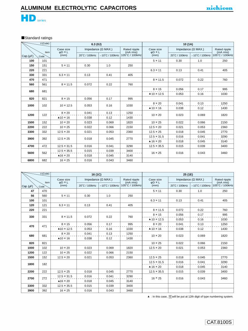
CAT.8100S
HD series
ALUMINUM ELECTROLYTIC CAPACITORS
: In this case, will be put at 12th digit of type numbering system.6
Standard ratings
100
150
220
330
470
560
680
820
1000
1200
1500
2200
3300
3900
4700
5600
6800
101
151
221
331
471
561
681
821
102
122
152
222
332
392
472
562
682
5 × 11
6.3 × 11
8 × 11.5
8 × 15
10 × 12.5
8 × 20
10 × 16
10 × 20
10 × 25
12.5 × 20
12.5 × 25
12.5 × 31.5
12.5 × 35.5
16 × 20
16 × 25
0.30
0.13
0.072
0.056
0.053
0.041
0.038
0.023
0.022
0.021
0.018
0.016
0.015
0.018
0.016
1.0
0.41
0.22
0.17
0.16
0.13
0.12
0.069
0.066
0.053
0.045
0.041
0.039
0.045
0.043
250
405
760
995
1030
1250
1430
1820
2150
2360
2770
3290
3400
3140
3460
5 × 11
6.3 × 11
8 × 11.5
8 × 15
10 × 12.5
8 × 20
10 × 16
10 × 20
10 × 25
12.5 × 20
12.5 × 25
12.5 × 31.5
16 × 20
12.5 × 35.5
16 × 25
0.30
0.13
0.072
0.056
0.053
0.041
0.038
0.023
0.022
0.021
0.018
0.016
0.018
0.015
0.016
1.0
0.41
0.22
0.17
0.16
0.13
0.12
0.069
0.066
0.053
0.045
0.041
0.045
0.039
0.043
250
405
760
995
1030
1250
1430
1820
2150
2360
2770
3290
3140
3400
3460
Cap.(µF)
V (Code) 6.3 (0J)
Case sizeφD × L(mm)
Impedance (Ω MAX.)
20˚C / 100kHz –10˚C / 100kHz
Rated ripple(mA rms)
105˚C / 100kHz
10 (1A)
Case sizeφD × L(mm)
Impedance (Ω MAX.)
20˚C / 100kHz –10˚C / 100kHz
Rated ripple(mA rms)
105˚C / 100kHzItem
Code
47
56
100
120
220
330
470
680
820
1000
1200
1500
1800
2200
2700
3300
3900
470
560
101
121
221
331
471
681
821
102
122
152
182
222
272
332
392
5 × 11
6.3 × 11
8 × 11.5
8 × 15
10 × 12.5
8 × 20
10 × 16
10 × 20
10 × 25
12.5 × 20
12.5 × 25
12.5 × 31.5
16 × 20
12.5 × 35.5
16 × 25
0.30
0.13
0.072
0.056
0.053
0.041
0.038
0.023
0.022
0.021
0.018
0.016
0.018
0.015
0.016
1.0
0.41
0.22
0.17
0.16
0.13
0.12
0.069
0.066
0.053
0.045
0.041
0.045
0.039
0.043
250
405
760
995
1030
1250
1430
1820
2150
2360
2770
3290
3140
3400
3460
Cap. (µF)
V (Code) 16 (1C)
Case sizeφD × L(mm)
Impedance (Ω MAX.)
20˚C / 100kHz –10˚C / 100kHz
Rated ripple(mA rms)
105˚C / 100kHz
25 (1E)
Case sizeφD × L(mm)
Impedance (Ω MAX.)
20˚C / 100kHz –10˚C / 100kHz
Rated ripple(mA rms)
105˚C / 100kHzItem
Code
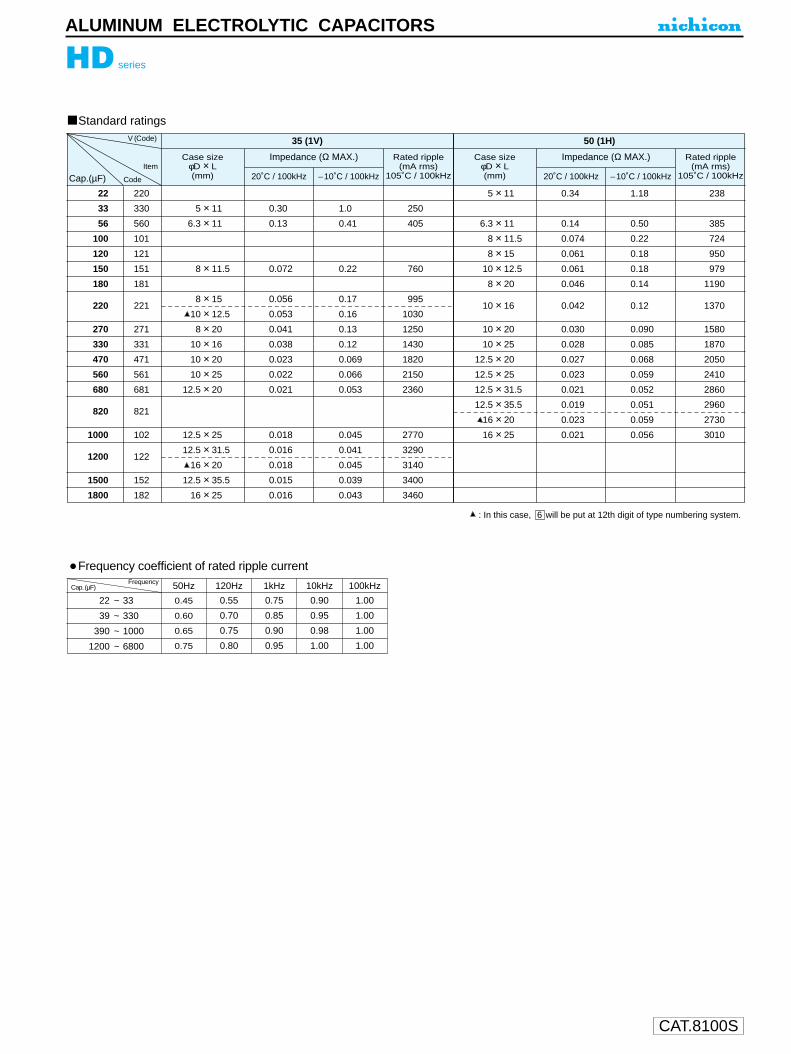
CAT.8100S
HD series
ALUMINUM ELECTROLYTIC CAPACITORS
: In this case, will be put at 12th digit of type numbering system.6
Standard ratings
22
33
56
100
120
150
180
220
270
330
470
560
680
820
1000
1200
1500
1800
220
330
560
101
121
151
181
221
271
331
471
561
681
821
102
122
152
182
5 × 11
6.3 × 11
8 × 11.5
8 × 15
10 × 12.5
8 × 20
10 × 16
10 × 20
10 × 25
12.5 × 20
12.5 × 25
12.5 × 31.5
16 × 20
12.5 × 35.5
16 × 25
0.30
0.13
0.072
0.056
0.053
0.041
0.038
0.023
0.022
0.021
0.018
0.016
0.018
0.015
0.016
1.0
0.41
0.22
0.17
0.16
0.13
0.12
0.069
0.066
0.053
0.045
0.041
0.045
0.039
0.043
250
405
760
995
1030
1250
1430
1820
2150
2360
2770
3290
3140
3400
3460
5 × 11
6.3 × 11
8 × 11.5
8 × 15
10 × 12.5
8 × 20
10 × 16
10 × 20
10 × 25
12.5 × 20
12.5 × 25
12.5 × 31.5
12.5 × 35.5
16 × 20
16 × 25
0.34
0.14
0.074
0.061
0.061
0.046
0.042
0.030
0.028
0.027
0.023
0.021
0.019
0.023
0.021
1.18
0.50
0.22
0.18
0.18
0.14
0.12
0.090
0.085
0.068
0.059
0.052
0.051
0.059
0.056
238
385
724
950
979
1190
1370
1580
1870
2050
2410
2860
2960
2730
3010
Cap.(µF)
V (Code) 35 (1V)
Case sizeφD × L(mm)
Impedance (Ω MAX.)
20˚C / 100kHz –10˚C / 100kHz
Rated ripple(mA rms)
105˚C / 100kHz
50 (1H)
Case sizeφD × L(mm)
Impedance (Ω MAX.)
20˚C / 100kHz –10˚C / 100kHz
Rated ripple(mA rms)
105˚C / 100kHzItem
Code
50Hz 120Hz 1kHz 10kHz 100kHz
0.75
0.85
0.90
0.95
0.90
0.95
0.98
1.00
Cap.(µF)Frequency
1.00
1.00
1.00
1.00
Frequency coefficient of rated ripple current
22 ~ 33
39 ~ 330
390 ~ 1000
1200 ~ 6800
0.55
0.70
0.75
0.80
0.45
0.60
0.65
0.75

CAT.8100S
ALUMINUM ELECTROLYTIC CAPACITORS
HE series
Miniature Sized, Low Impedance,High Reliability
Low impedance and high reliability withstanding 4000hours to 10000hours.
Specifications
Approved by Reliability Center for ElectronicComponent, Japan-Certification No. RCJ-03-23C
Please refer to page 19, 20, 21 about the formed or taped product spec.Please refer to page 3 for the minimum order quantity.
Radial Lead Type Type numbering system (Example : 10V 1000µF)
U1
H2
E3
14
A5
16
07
28
M9
P10
D11 12
Capacitance tolerance (± 20%)
Size code
Rated Capacitance (1000µF)
Rated voltage (10V)
Configuration
Series name
Type
(mm)
φD
P
φd
10
5.0
0.6
5
2.0
0.5
12.5
5.0
16
7.5
0.6 0.8
18
7.5
0.8
6.3
2.5
0.5 0.6
8
3.5
P±0
.5
15MIN 4MIN
φD+
0.5
MA
X
φd
Pressurerelief vent
(φ6.3up)
In case L > 25 for the φ12.5 dia. unit, lead dia. φd = 0.8mm
L+ MAX
(L < 20) 1.5(L 20) 2.0
Sleeve (P.E.T.)
φ D
5
Pb free lead finishingPb free PET sleeve
Sn-Pb lead finishingPVC sleeve contain Pb
DD DH
6.3 ED EH
8 · 10 PD PH
12.5 ~ 18 HD HH
Configuration
Please contact to us if other configurations are required.
Performance Characteristicsltem
0.22 0.19 0.16 0.14 0.12 0.10 0.09 0.08
Category Temperature Range
Rated Voltage Range
Rated Capacitance Range
Capacitance Tolerance
Leakage Current
tan δ
Stability at Low Temperature
Endurance
Shelf Life
–40 ~ +105˚C
6.3 ~ 100V
6.8 ~ 18000µF
±20% at 120Hz, 20˚C
After 2 minutes' application of rated voltage, leakage current is not more than 0.01CV or 3 (µA), whichever is greater.
Rated voltage (V)
Rated voltage (V)
Case size φD <= 6.3 φD = 8 , 10 φD >= 12.5
tan δ (MAX.)
For capacitance of more than 1000µF, add 0.02 for every increase of 1000µF.
Z–25˚C / Z+20˚C
6.3 ~ 10WV 4000hours 6000hours 8000hours
5000hours 7000hours 10000hours
Z–40˚C / Z+20˚C
16 ~ 100WV
Impedance ratio
ZT / Z20 (MAX.)
Rated voltage(V)
6.3 10 16 25 35 50 63 100
4 3 2 2 2 2 2 2
8 6 4 3 3 3 3 3
6.3 10 16 25 35 50 63 100
After an application of D.C. bias voltage plus the rated ripple current for stated in the below at 105˚C the peak voltage shall notexceed the rated D.C. voltage, capacitors shall meet the following requirements.
After leaving capacitors under no load at 105˚C for 1000 hours, they meet the specified value for endurance characteristicslisted above.
Marking Printed with white color letter on black sleeve.
Capacitance change Within ± 25% of initial value
tan δ 200% or less of initial specified value
Leakage current lnitial specified value or less
120Hz
20˚C
120Hz
HE
HDLong Life
6.8 ~ 33
39 ~ 330
390 ~ 1000
1200 ~ 18000
0.55
0.70
0.75
0.80
50Hz 120Hz 300Hz 1kHz
0.45
0.60
0.65
0.75
0.70
0.85
0.90
0.95
0.90
0.95
0.98
1.00
10kHz~
1.00
1.00
1.00
1.00
Cap. (µF) Frequency
Frequency coefficient of rated ripple current
Dimension table in next page.

CAT.8100S
ALUMINUM ELECTROLYTIC CAPACITORS
HE series
100
150
220
330
470
680
820
1000
1200
1500
1800
2200
2700
3300
3900
4700
5600
6800
8200
10000
12000
15000
18000
101
151
221
331
471
681
821
102
122
152
182
222
272
332
392
472
562
682
822
103
123
153
183
5 × 11
6.3 × 11
8 × 11.5
10 × 12.5
8 × 15
8 × 20
10 × 16
10 × 20
12.5 × 15
10 × 25
10 × 31.5
16 × 15
12.5 × 20
12.5 × 25
18 × 15
12.5 × 31.5
12.5 × 35.5
16 × 20
12.5 × 40
16 × 25
18 × 20
16 × 31.5
16 × 35.5
18 × 25
16 × 40
18 × 31.5
18 × 35.5
18 × 40
0.58
0.22
0.13
0.080
0.087
0.069
0.060
0.046
0.049
0.042
0.031
0.042
0.035
0.027
0.043
0.024
0.020
0.027
0.017
0.021
0.026
0.017
0.015
0.019
0.013
0.015
0.014
0.012
2.3
0.87
0.52
0.32
0.35
0.27
0.24
0.18
0.16
0.17
0.12
0.12
0.12
0.089
0.11
0.078
0.065
0.078
0.056
0.060
0.067
0.050
0.044
0.049
0.038
0.040
0.038
0.032
210
340
640
865
840
1050
1210
1400
1450
1650
1910
1940
1900
2230
2210
2650
2880
2530
3350
2930
2860
3450
3610
3140
4080
4170
4220
4280
5 × 11
6.3 × 11
8 × 11.5
8 × 15
10 × 12.5
8 × 20
10 × 16
10 × 20
10 × 25
12.5 × 15
10 × 31.5
12.5 × 20
16 × 15
18 × 15
12.5 × 25
12.5 × 31.5
16 × 20
12.5 × 35.5
12.5 × 40
16 × 25
18 × 20
16 × 31.5
18 × 25
16 × 35.5
18 × 31.5
16 × 40
18 × 35.5
18 × 40
0.58
0.22
0.13
0.087
0.080
0.069
0.060
0.046
0.042
0.049
0.031
0.035
0.042
0.043
0.027
0.024
0.027
0.020
0.017
0.021
0.026
0.017
0.019
0.015
0.015
0.013
0.014
0.012
2.3
0.87
0.52
0.35
0.32
0.27
0.24
0.18
0.17
0.16
0.12
0.12
0.12
0.11
0.089
0.078
0.078
0.065
0.056
0.060
0.067
0.050
0.049
0.044
0.040
0.038
0.038
0.032
210
340
640
840
865
1050
1210
1400
1650
1450
1910
1900
1940
2210
2230
2650
2530
2880
3350
2930
2860
3450
3140
3610
4170
4080
4220
4280
Case sizeφD × L(mm)
Rated ripple
(mA rms)105˚C / 100kHz20˚C / 100kHz –10˚C / 100kHz
Impedance (Ω MAX.)
6.3 (0J)
Case sizeφD × L(mm)
Rated ripple
(mA rms)105˚C / 100kHz20˚C / 100kHz –10˚C / 100kHz
Impedance (Ω MAX.)
10 (1A)V (Code)
Item
Cap.(µF)
: In this case, 6 will be put 12th digit type numbering system. : In this case, 3 will be put 12th digit type numbering system.
Code
Standard ratings

CAT.8100S
ALUMINUM ELECTROLYTIC CAPACITORS
HE series
47
56
100
120
220
330
470
680
820
1000
1200
1500
1800
2200
2700
3300
3900
4700
5600
6800
8200
10000
470
560
101
121
221
331
471
681
821
102
122
152
182
222
272
332
392
472
562
682
822
103
5 × 11
6.3 × 11
8 × 11.5
8 × 15
10 × 12.5
8 × 20
10 × 16
10 × 20
12.5 × 15
10 × 25
10 × 31.5
12.5 × 20
16 × 15
12.5 × 25
18 × 15
12.5 × 31.5
16 × 20
12.5 × 35.5
12.5 × 40
16 × 25
16 × 20
16 × 31.5
18 × 25
16 × 35.5
18 × 31.5
16 × 40
18 × 35.5
18 × 40
0.58
0.22
0.13
0.087
0.080
0.069
0.060
0.046
0.049
0.042
0.031
0.035
0.042
0.027
0.043
0.024
0.027
0.020
0.017
0.021
0.026
0.017
0.019
0.015
0.015
0.013
0.014
0.012
2.3
0.87
0.52
0.35
0.32
0.27
0.24
0.18
0.16
0.17
0.12
0.12
0.12
0.089
0.11
0.078
0.078
0.065
0.056
0.060
0.067
0.050
0.049
0.044
0.040
0.038
0.038
0.032
210
340
640
840
865
1050
1210
1400
1450
1650
1910
1900
1940
2230
2210
2650
2530
2880
3350
2930
2860
3450
3140
3610
4170
4080
4220
4280
5 × 11
6.3 × 11
8 × 11.5
8 × 15
10 × 12.5
8 × 20
10 × 16
10 × 20
12.5 × 15
10 × 25
10 × 31.5
12.5 × 20
16 × 15
18 × 15
12.5 × 25
12.5 × 31.5
16 × 20
12.5 × 35.5
18 × 20
12.5 × 40
16 × 25
16 × 31.5
18 × 25
16 × 35.5
18 × 31.5
16 × 40
18 × 35.5
18 × 40
0.58
0.22
0.13
0.087
0.080
0.069
0.06
0.046
0.049
0.042
0.031
0.035
0.042
0.043
0.027
0.024
0.027
0.020
0.026
0.017
0.021
0.017
0.019
0.015
0.015
0.013
0.014
0.012
2.3
0.87
0.52
0.35
0.32
0.27
0.24
0.18
0.16
0.17
0.12
0.12
0.12
0.11
0.089
0.078
0.078
0.065
0.067
0.056
0.060
0.050
0.049
0.044
0.040
0.038
0.038
0.032
210
340
640
840
865
1050
1210
1400
1450
1650
1910
1900
1940
2210
2230
2650
2530
2880
2860
3350
2930
3450
3140
3610
4170
4080
4220
4280
Case sizeφD × L(mm)
Rated ripple
(mA rms)105˚C / 100kHz20˚C / 100kHz –10˚C / 100kHz
Impedance (Ω MAX.)
16 (1C)
Case sizeφD × L(mm)
Rated ripple
(mA rms)105˚C / 100kHz20˚C / 100kHz –10˚C / 100kHz
Impedance (Ω MAX.)
25 (1E)V (Code)
Item
CodeCap.(µF)
: In this case, 6 will be put 12th digit type numbering system. : In this case, 3 will be put 12th digit type numbering system.
Standard ratings
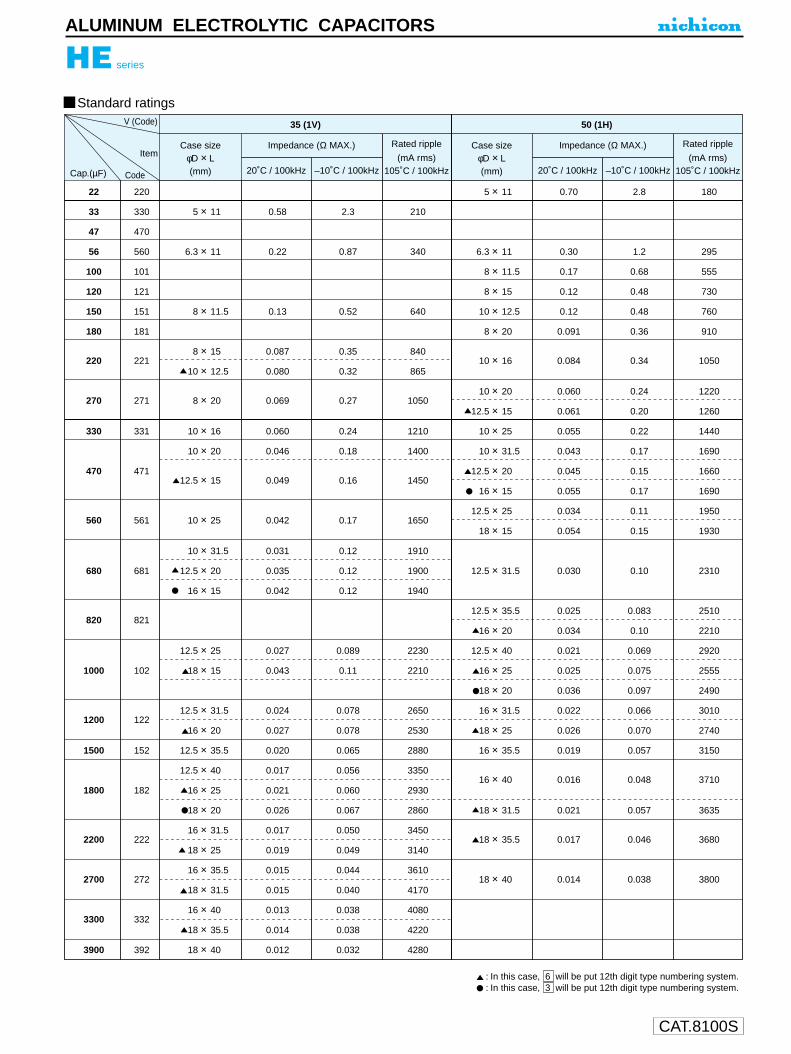
CAT.8100S
ALUMINUM ELECTROLYTIC CAPACITORS
HE series
22
33
47
56
100
120
150
180
220
270
330
470
560
680
820
1000
1200
1500
1800
2200
2700
3300
3900
220
330
470
560
101
121
151
181
221
271
331
471
561
681
821
102
122
152
182
222
272
332
392
5 × 11
6.3 × 11
8 × 11.5
8 × 15
10 × 12.5
8 × 20
10 × 16
10 × 20
12.5 × 15
10 × 25
10 × 31.5
12.5 × 20
16 × 15
12.5 × 25
18 × 15
12.5 × 31.5
16 × 20
12.5 × 35.5
12.5 × 40
16 × 25
18 × 20
16 × 31.5
18 × 25
16 × 35.5
18 × 31.5
16 × 40
18 × 35.5
18 × 40
0.58
0.22
0.13
0.087
0.080
0.069
0.060
0.046
0.049
0.042
0.031
0.035
0.042
0.027
0.043
0.024
0.027
0.020
0.017
0.021
0.026
0.017
0.019
0.015
0.015
0.013
0.014
0.012
2.3
0.87
0.52
0.35
0.32
0.27
0.24
0.18
0.16
0.17
0.12
0.12
0.12
0.089
0.11
0.078
0.078
0.065
0.056
0.060
0.067
0.050
0.049
0.044
0.040
0.038
0.038
0.032
210
340
640
840
865
1050
1210
1400
1450
1650
1910
1900
1940
2230
2210
2650
2530
2880
3350
2930
2860
3450
3140
3610
4170
4080
4220
4280
5 × 11
6.3 × 11
8 × 11.5
8 × 15
10 × 12.5
8 × 20
10 × 16
10 × 20
12.5 × 15
10 × 25
10 × 31.5
12.5 × 20
16 × 15
12.5 × 25
18 × 15
12.5 × 31.5
12.5 × 35.5
16 × 20
12.5 × 40
16 × 25
18 × 20
16 × 31.5
18 × 25
16 × 35.5
16 × 40
18 × 31.5
18 × 35.5
18 × 40
0.70
0.30
0.17
0.12
0.12
0.091
0.084
0.060
0.061
0.055
0.043
0.045
0.055
0.034
0.054
0.030
0.025
0.034
0.021
0.025
0.036
0.022
0.026
0.019
0.016
0.021
0.017
0.014
2.8
1.2
0.68
0.48
0.48
0.36
0.34
0.24
0.20
0.22
0.17
0.15
0.17
0.11
0.15
0.10
0.083
0.10
0.069
0.075
0.097
0.066
0.070
0.057
0.048
0.057
0.046
0.038
180
295
555
730
760
910
1050
1220
1260
1440
1690
1660
1690
1950
1930
2310
2510
2210
2920
2555
2490
3010
2740
3150
3710
3635
3680
3800
Case sizeφD × L(mm)
Rated ripple
(mA rms)105˚C / 100kHz20˚C / 100kHz –10˚C / 100kHz
Impedance (Ω MAX.)
35 (1V)
Case sizeφD × L(mm)
Rated ripple
(mA rms)105˚C / 100kHz20˚C / 100kHz –10˚C / 100kHz
Impedance (Ω MAX.)
50 (1H)
Standard ratingsV (Code)
Item
CodeCap.(µF)
: In this case, 6 will be put 12th digit type numbering system.: In this case, 3 will be put 12th digit type numbering system.

CAT.8100S
ALUMINUM ELECTROLYTIC CAPACITORS
HE series
6.8
15
27
33
39
47
56
68
82
100
120
150
180
220
270
330
390
470
560
680
820
1000
1200
1500
6R8
150
270
330
390
470
560
680
820
101
121
151
181
221
271
331
391
471
561
681
821
102
122
152
5 × 11
6.3 × 11
8 × 11.5
8 × 15
10 × 12.5
8 × 20
10 × 16
10 × 20
12.5 × 15
10 × 25
10 × 31.5
12.5 × 20
16 × 15
12.5 × 25
18 × 15
12.5 × 31.5
16 × 20
12.5 × 35.5
16 × 25
12.5 × 40
18 × 20
16 × 31.5
18 × 25
16 × 35.5
18 × 31.5
16 × 40
18 × 35.5
18 × 40
2.3
1.2
0.63
0.45
0.43
0.33
0.31
0.21
0.23
0.20
0.15
0.16
0.14
0.12
0.12
0.10
0.091
0.083
0.073
0.071
0.080
0.054
0.057
0.045
0.047
0.040
0.040
0.036
9.3
5.0
2.8
2.1
1.8
1.6
1.5
0.94
1.1
0.84
0.71
0.64
0.66
0.45
0.50
0.42
0.38
0.35
0.27
0.30
0.30
0.20
0.21
0.17
0.17
0.15
0.15
0.13
55
115
232
300
288
362
357
466
466
531
663
690
795
784
920
905
1040
1050
1250
1180
1240
1570
1490
1790
1630
2020
1790
2330
5 × 11
6.3 × 11
8 × 11.5
8 × 15
10 × 12.5
8 × 20
10 × 16
10 × 20
12.5 × 15
10 × 25
10 × 31.5
12.5 × 20
16 × 15
12.5 × 25
18 × 15
12.5 × 31.5
16 × 20
12.5 × 35.5
16 × 25
12.5× 40
18 × 20
16 × 31.5
18 × 25
16 × 35.5
18 × 31.5
16 × 40
18 × 35.5
18 × 40
2.3
1.2
0.63
0.45
0.43
0.33
0.31
0.21
0.23
0.20
0.15
0.16
0.14
0.12
0.12
0.10
0.091
0.083
0.073
0.071
0.080
0.054
0.057
0.045
0.047
0.040
0.040
0.036
9.3
5.0
2.8
2.1
1.8
1.6
1.5
0.94
1.1
0.84
0.71
0.64
0.66
0.45
0.50
0.42
0.38
0.35
0.27
0.30
0.30
0.20
0.21
0.17
0.17
0.15
0.15
0.13
55
115
232
300
288
362
357
466
466
531
663
690
795
784
920
905
1040
1050
1250
1180
1240
1570
1490
1790
1630
2020
1790
2330
Case sizeφD × L(mm)
Rated ripple
(mA rms)105˚C / 100kHz20˚C / 100kHz –10˚C / 100kHz
Impedance (Ω MAX.)
63 (1J)
Case sizeφD × L(mm)
Rated ripple
(mA rms)105˚C / 100kHz20˚C / 100kHz –10˚C / 100kHz
Impedance (Ω MAX.)
100 (2A)
Standard ratingsV (Code)
Item
CodeCap.(µF)
: In this case, 6 will be put 12th digit type numbering system. : In this case, 3 will be put 12th digit type numbering system.
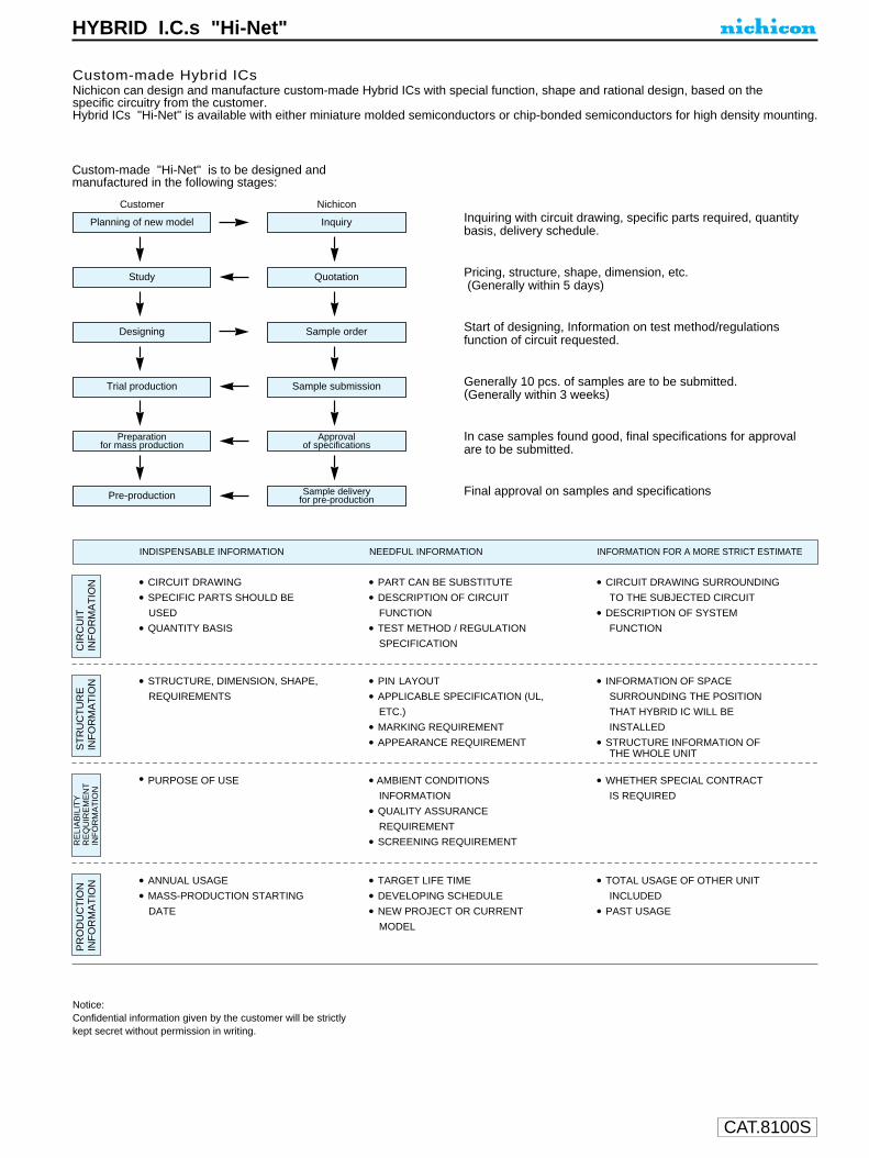
CAT.8100S
HYBRID I.C.s "Hi-Net"
• CIRCUIT DRAWING • PART CAN BE SUBSTITUTE • CIRCUIT DRAWING SURROUNDING
• SPECIFIC PARTS SHOULD BE • DESCRIPTION OF CIRCUIT TO THE SUBJECTED CIRCUIT
USED FUNCTION • DESCRIPTION OF SYSTEM
• QUANTITY BASIS • TEST METHOD / REGULATION FUNCTION
SPECIFICATION
• STRUCTURE, DIMENSION, SHAPE, • PIN LAYOUT • INFORMATION OF SPACE
REQUIREMENTS • APPLICABLE SPECIFICATION (UL, SURROUNDING THE POSITION
ETC.) THAT HYBRID IC WILL BE
• MARKING REQUIREMENT INSTALLED
• APPEARANCE REQUIREMENT • STRUCTURE INFORMATION OFTHE WHOLE UNIT
• PURPOSE OF USE • AMBIENT CONDITIONS • WHETHER SPECIAL CONTRACT
INFORMATION IS REQUIRED
• QUALITY ASSURANCE
REQUIREMENT
• SCREENING REQUIREMENT
• ANNUAL USAGE • TARGET LIFE TIME • TOTAL USAGE OF OTHER UNIT
• MASS-PRODUCTION STARTING • DEVELOPING SCHEDULE INCLUDED
DATE • NEW PROJECT OR CURRENT • PAST USAGE
MODEL
Notice:Confidential information given by the customer will be strictlykept secret without permission in writing.
Custom-made Hybrid ICsNichicon can design and manufacture custom-made Hybrid ICs with special function, shape and rational design, based on thespecific circuitry from the customer.Hybrid ICs "Hi-Net" is available with either miniature molded semiconductors or chip-bonded semiconductors for high density mounting.
Custom-made "Hi-Net" is to be designed andmanufactured in the following stages:
Planning of new model
Customer
Inquiry
NichiconInquiring with circuit drawing, specific parts required, quantitybasis, delivery schedule.
Pricing, structure, shape, dimension, etc.(Generally within 5 days)
Start of designing, Information on test method/regulationsfunction of circuit requested.
Generally 10 pcs. of samples are to be submitted.(Generally within 3 weeks)
In case samples found good, final specifications for approvalare to be submitted.
Final approval on samples and specifications
Study Quotation
Designing Sample order
Trial production Sample submission
Preparationfor mass production
Approvalof specifications
Pre-production Sample deliveryfor pre-production
INDISPENSABLE INFORMATION NEEDFUL INFORMATION INFORMATION FOR A MORE STRICT ESTIMATE
CIR
CU
ITIN
FO
RM
AT
ION
ST
RU
CT
UR
EIN
FO
RM
AT
ION
RE
LIA
BIL
ITY
RE
QU
IRE
ME
NT
INF
OR
MA
TIO
N
PR
OD
UC
TIO
NIN
FO
RM
AT
ION

CAT.8100S
HYBRID I.C.s "Hi-Net"
Standard Type DC-DC Converter (1.5W 3W 6W 10W)We can comply with various types of converters includingDIP type and SIP type.
Characteristics
Specification
(1) Thin and lightweight(2) Excellent heat radiation and miniaturization due to alumina substrate(3) Excellent isolation ability between input and output(4) No attachment necessary(5) Circuit with built-in excess current protection
Output ToleranceOver Current ProtectionWithstanding Voltage
±5%Functions at 105% or more of the rated output current Automatically restoredBetween input and output AC500V for 1minute 5mA
:::
Insulation Resistance
Operating Temperature/HumidityStorage Temperature/Humidity
Between input and output terminals DC500V, more than 100MΩ (25˚C 70%)-10 ~ +71˚C 20 ~ 95%RH (No dewdrops)-40 ~ +85˚C 20 ~ 95%RH (No dewdrops)
:
::
OutputPower Input Voltage
OutputVoltage Output Current Part Number
Style code
B C D E
MeasurementStyleNo.
Efficie-ncy L W H S
4.5 ~ 7.2V
(5VTYP)
8 ~ 16.5V
(12VTYP)
18 ~ 32V
(24VTYP)
4.5 ~ 7.2V(5VTYP)
8 ~ 16.5V(12VTYP)
18 ~ 32V(24VTYP)
4.5 ~ 7.2V
(5VTYP)
8 ~ 16.5V
(12VTYP)
18 ~ 32V
(24VTYP)
4.5 ~ 7.2V(5VTYP)
8 ~ 16.5V(12VTYP)
18 ~ 32V(24VTYP)
4.5 ~ 7.2V
(5VTYP)
8 ~ 16.5V
(12VTYP)
18 ~ 32V
(24VTYP)
4.5 ~ 7.2V(5VTYP)
8 ~ 16.5V(12VTYP)
18 ~ 32V(24VTYP)
4.5 ~ 7.2V
(5VTYP)
8 ~ 16.5V
(12VTYP)
18 ~ 32V
(24VTYP)
4.5 ~ 7.2V(5VTYP)
8 ~ 16.5V(12VTYP)
18 ~ 32V(24VTYP)
5V12V15V5V12V15V5V12V15V
±12V±15V±12V±15V±12V±15V
5V12V15V5V12V15V5V12V15V
±12V±15V±12V±15V±12V±15V
5V12V15V5V12V15V5V12V15V
±12V±15V±12V±15V±12V±15V
5V12V15V5V12V15V5V12V15V
±12V±15V±12V±15V±12V±15V
300mA125mA100mA300mA125mA100mA300mA125mA100mA±63mA±50mA±63mA±50mA±63mA±50mA600mA250mA200mA600mA250mA200mA600mA250mA200mA
±125mA±100mA±125mA±100mA±125mA±100mA
1.0A0.5A0.4A1.2A0.5A0.4A1.2A0.5A0.4A
±0.25A±0.20A±0.25A±0.20A±0.25A±0.20A1.60A0.70A0.60A2.00A0.84A0.67A2.00A0.84A0.67A
±0.35A±0.30A±0.42A±0.34A±0.42A±0.34A
68%70%71%72%73%74%73%76%76%70%68%71%73%72%74%72%77%77%74%80%80%76%81%81%72%75%74%75%74%76%76%76%76%82%84%84%83%86%86%79%79%84%84%85%85%76%76%76%83%83%83%84%84%84%79%79%84%85%84%85%
ZHRM0600505C0512C0515C1205C1212C1215C2405C2412C2415C
ZHRP0600512C0515C1212C1215C2412C2415C
ZHRM1000505C0512C0515C1205C1212C1215C2405C2412C2415C
ZHRP1000512C0515C1212C1215C2412C2415C
ZHRM1R5050505120515120512121215240524122415
ZHRP1R5051205151212121524122415
ZHRM030050505120515120512121215240524122415
ZHRP030051205151212121524122415
1.5W
3W
6W
10W
OutputPower
1.5W
3W
6W
10W
B
C
D
E
B
C
D
E
C
C
26.5±0.2
28.0MAX
26.0MAX
17.4±0.2
18.7MAX
16.5MAX
26.5MAX
8.1MAX
8.8MAX
7.3MAX
18.0MAX
24.95±0.5
24.95±0.5
24.95±0.5
T=10.5MAX (Single Output)
T= 9.0MAX (Double Output)
34.5±0.2
36.0MAX
34.0MAX
24.7±0.2
26.0MAX
23.5MAX
29.5MAX
8.8MAX
9.5MAX
7.5MAX
21.0MAX
32.95±0.5
32.95±0.5
32.95±0.5
T=11.0MAX
40.5±0.5 25.8±0.5 11.5MAX 37.45±0.5
41.0±0.5 31.8±0.5 13.5MAX 37.45±0.5
StyleCode
: Style code Except : Accept an order
1
2
4
1
2
3
4
2
2
3

CAT.8100S
HYBRID I.C.s "Hi-Net"
2.5
4±0
.2
0.5
±0.1
L
S
W
H =3.7±0.7
1
2
10
9
8
7
6
0.25±0.1
4
5
A
Enlarged figure of"A" part.
H
L
W
S
26.0±0.1
H
12
1615
109
0.25±0.1
2.5
4±0
.20
.5±0
.1
78
3.7±1.0
A
3.02.0
0.5
Enlarged figure of "A" part.
L
W
S
26.0±0.1
H
12
2019
1211
0.25±0.1
2.5
4±0
.20
.5±0
.1
910
3.7±1.0
A
3.02.0
0.5
Enlarged figure of "A" part.
2.5
4±0
.20
.5±0
.1
S0.25±0.1
H =3.7±0.7
Enlarged figure of"A" part.
H
L
W
1
2
10
9
8
7
6
4
5
A
Acrylic Resin Coating
=3
.7±0
.7
2.54±0.2
1 2 3 4 7 8 9
0.5±0.1 0.25±0.1
Enlarged figure of"A" part.
H
A
W T
H
Phenol ResinCoating
=3
.7±0
.7
2.54±0.2
1 2 3 4 8 9 10
0.5±0.1 0.25±0.1
Enlarged figure of"A" part.
H
A
W T
H
Phenol ResinCoating
L
W
1
2
16
15
11109
7
8
0.5
±0.1
S
H =3.7±0.7
0.25±0.1
A
Enlarged figure of"A" part.
H2
.54±0
.2
L
W
2.5
4±0
.20
.5±0
.1
12
16
15
11
10
9
S0.25±0.1
H =3.7±0.7
Enlarged figure of"A" part.
H
78
A
Acrylic Resin Coating
Exterior and Measurement Map
DIP
Typ
eS
IP T
ype
(1.5W) (3W)
(1.5W) (3W)
(1.5W) (3W)
(6W) (10W)
Resin Case 1.5W 3W Only Flow Compliant
Resin Coating Low Cost DIP Style
Resin Coating Low Cost Horizontal Type, Space Saver
Steel Cover Reduce Radiation Noise
1
2
3
4

CAT.8100S
HYBRID I.C.s "Hi-Net"
Diode ArraysHigh-speed switching diode arrays are of NICHICON's standard series. They are combined tobe conveniently used for both binary and decimal systems. High-speed series is ideal forcomputer peripherals, control boards and general electronic appliances.These series are in stock for prompt delivery. Any special requirements with customer'sparticular circuits will be also welcome. Please consult us for the details.(Samples for the items listed below are not always available on stock. Please contact our sales office for details together withyour specific requirements.)
High-speed switching diode array seriesAbsolute maximum ratings
Electrical characteristics
Series List
100mA for simultaneous energizing.
Ta : +25°C
ZHMA0423
ZHMA0424
ZHMA0425
ZHMA0426
ZHMA0427
ZHMA0428
ZHMA0429
ZHMA0430
ZHMA0431
ZHMA0432
MA423
MA424
MA425
MA426
MA427
MA428
MA429
MA430
MA431
MA432
4
8
10
5
4
6
Cathode
Anode
Cathode
Anode
Cathode
Anode
Isolated
Isolated
Cathode
Anode
14
24
29
27
21.5
19
9
9
9
9
9
9
3.5
3.5
3.5
3.5
3.5
3.5
5
9
11
10
8
7
1
2
1
2
1
2
3
3
1
2
Code Type Number ofdiodes
Commonelectrode
Dimensions (m/m Max.) No.ofPins
W H T nCircuit diagram
Items Symbol Ratings
Peak reverse voltage VRM 40V
DC reverse voltage VR 40V
Surge current (1µs) IFSM 4.0A
Peak forward current IFM 300mA
Average rectified current I0 100mA
Storage temperature Tstg –25 ~ +85°C
Items Symbol ConditionsRating
UnitMin. Typ. Max.
Reverse current IR VR=40V — — 0.5 µA
Forward voltage VF1 IF=10mA — 0.7 1.0 V
Forward voltage VF2 IF=50mA — 0.79 1.0 V
Forward voltage VF3 IF=100mA — 0.85 1.2 V
Reverse recovery time trr IF=10mA, VR=6V — — 4.0 ns
1 2 3 n
1
1 n2 3
2
n-1 n
3
DrawingW
T
1 2 3
2.54±0.2
H
0.250.5 3MIN
n
MARKING
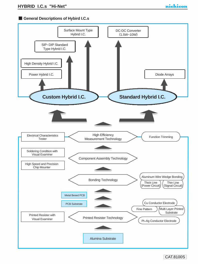
CAT.8100S
HYBRID I.C.s "Hi-Net"
Multi Layer PrintedSubstrate
Fine Pattern
General Descriptions of Hybird I.C.s
Surface Mount TypeHybrid I.C.
DC-DC Converter(1.5W~10W)
SIP • DIP StandardType Hybrid I.C.
Diode Arrays
High Density Hybrid I.C.
Power Hybrid I.C.
Custom Hybrid I.C. Standard Hybrid I.C.
High EfficiencyMeasurement Technology
Component Assembly Technology
Bonding Technology
Printed Resister TechnologyPrinted Resister with
Visual Examiner
Alumina Substrate
PCB Substrate
Metal Besed PCB
Thick Line(Power Circuit)
Thin Line(Signal Circuit)
High Speed and PrecisionChip Mounter
Soldering Condition withVisual Examiner
Electrical CharacteristicsTester
Cu Conductor Electrode
Pt–Ag Conductor Electrode
Aluminum Wire Wedge Bonding
Function Trimming

CAT.8100S
HYBRID I.C.s "Hi-Net"
Hybrid IC Technologies
Copper Line Platinum / Silver Line
It is the most suitable material for the circuits that require high frequency and current.High-density circuits such as fine pattern and multi layer printing can minimize the sizes of the products.Since metal migration does not occur, copper is highly reliable.
Platinum and silver lines are frequently used for automobiles since they have high performance of withstanding heat cycle and are highly reliable.
Printed Resistor Technology
It is possible to create highly efficient thick film resistors by introducing the ruthenium oxide.The printing machine with visual examiner offers high reliability.

CAT.8100S
HYBRID I.C.s "Hi-Net"
Bonding Technology
Function Trimming
Various Technologies
Mounting Structure
Aluminum Wire Wedge Bonding
Signal Line Type Power Line Type
When semiconductor chips are bonded and unified with surrounding circuits, it is possible to get ultra miniature and high-density modules.
The diameter of wires can be selected according to the purpose or usage (25um~200um). Also, the aluminum wire can be bonded without applying heat.
Due to the narrow wire pitch and low profile bonding, thin and high-density hybrid ICs, that are based on alumina board or printed board, can be achieved.
It is possible to get a power module based on an alumina or a metal board, which is highly efficient in radiating heat.
By utilizing the highly efficient measurement technology, we laser-trim the registor in order to meet the required resistance value. By using function trimming, we can remove mechanical adjusters. This eliminates mechanical failures in sueface mount registors.By removing the mechanical adjuster, we can also achieve long term reliability, and it helps to save labors and eliminate a manufacturing process.
By using a soldering condition tester, which checks mounting conditions and an efficient high speed chip mounter, we can achieve intricate and rapid soldering.
In addition to the SIP and DIP types, you can select from various types of package styles.Also, we can customize according to your needs.
General Observations1. If parts are covered with a liquid—water, oil, etc., or any metallic material, this can cause part failure.
Do not use the parts.2. If voltage in excess of the rated voltage is applied the parts can fail and possibly flame out.3. If parts are used with reactive gas, strong electrical field, or radioactive environment, parts will deteriorate greatly.
Notes on Usage1. Please use parts within rated operating temperatures.2. Please use parts within the rated voltages and applicable current.3. Please use parts in a cooled down environment by using either heat sinks or fans to deflect heat.4. Do not put excessive force onto the terminals.5. Please use parts in stress-free environment with the exception of those meant to be bolted to the PC board.6. Soldering conditions should be as follows: 260 degrees C maximum for no more than 5 seconds and cool down quickly to roomtemperatures.
Take special precaution in controlling soldering conditions because the solder can very adversely affect the hybrid IC.7. The part reliability will vary due to the environmental conditions of the application.
Please verify the quality by testing the parts in actual environmental conditions.8. Please use parts in accordance with the individual drawings.9. Please use these parts with some protection against personal injury from possible fire.
Notes on StoragePlease store parts at normal room temperature, humidity and barometric pressure.
APPLICATION GUIDELINES FOR HYBRID I.C.s "Hi-Net"
CAT.8100S
HYBRID I.C.s "Hi-Net"

CAT.8100S
HYBRID I.C.s "Hi-Net"
Hybrid I.C. for Control Circuit of Power Supply
Higher Harmonics (MA6400B)
Feature
27.5W × 19H × 5T (mm)
(Code ZHMA6400B)
This control circuit suited for power supplies and inverters for the higherharmonics application.Very high power factor improvement can be obtained by boostingchopper circuitry.
Applied circuit
REG
VDET VS
VCC OUT+
9 2 1
6
8
10
7 5IDET GND VFB

CAT.8100S
ALUMINUM ELECTROLYTIC CAPACITORS
HM series
Low Impedance
Lower impedance than HD,HC series.
Please refer to page 19, 20, 21 about the formed or taped product spec.Please refer to page 3 for the minimum order quantity.
HM HDLowImpedance
8 × 11.5
8 × 11.58 × 15
10 × 12.58 × 11.5
8 × 1510 × 12.58 × 20
10 × 1610 × 168 × 20
10 × 208 × 20
10 × 1610 × 2010 × 25
12.5 × 2010 × 20
12.5 × 25
16 × 2518 × 25
Specifications
Radial Lead Type Type numbering system (Example : 6.3V 1800µF)
Performance Characteristicsltem
0.22 0.19 0.16
Category Temperature RangeRated Voltage Range Rated Capacitance Range Capacitance ToleranceLeakage Current
tan δ
Stability at Low Temperature
Endurance
Marking
—40 ~ +105˚C6.3 ~ 16V330 ~ 12000µF±20% (120Hz, 20˚C)After 2 minutes' application of rated voltage, leakage current is less than 0.03CVFor capacitance of more than 1000µF, add 0.02 for every increase of 1000µF
Rated voltage (V)
Rated voltage (V)tan δ (MAX.)
Impedance ratio ZT / Z20 (MAX.) Z—40˚C / Z+20˚C
6.3 10 16
6.33 3 3
10 16
After an application of D.C. bias voltage plus the rated ripple current for 2000 hours at 105˚C the peak voltage shall notexceed the rated D.C. voltage, capacitors meet the characteristic requirements listed below.
Printed with white color black sleeve.
Capacitance change Within ±25% of initial valuetan δ 200% or less of initial specified valueLeakage current lnitial specified value or less
120Hz20˚C
120Hz
Standard ratingsV (Code) 6.3 (0J) 10 (1A) 16 (1C)
Case sizeφD × L(mm)
Case sizeφD × L(mm)
Impedance(mΩ MAX.)
20˚C / 100kHz
Impedance(mΩ MAX.)
20˚C / 100kHz
Rated ripple(mA rms)
105˚C / 100kHz
Rated ripple(mA rms)
105˚C / 100kHz
Case sizeφD × L(mm)
Impedance(mΩ MAX.)
20˚C / 100kHz
Rated ripple(mA rms)
105˚C / 100kHz
Item
Cap.(µF) Code
U1
H2
M3
04
J5
16
87
28
M9
P10
D11 12
φD
P
φd
8
3.5
0.6
10
5.0
0.6
P±0
.5
L+1.5 MAX 15MIN 4MIN
φD+
0.5
MA
X
Pressurerelief vent
φd
Capacitance tolerance (±20%)
Rated Capacitance (1800µF)
Rated voltage (6.3V)
Configuration
Case Size Code
Series name
Type
12.5
5.0
0.6
16
7.5
0.8
18
7.5
0.8
330
470
560
680
820
1000
1200
1500
1800
2200
2700
3300
560068008200
12000
331
471
561
681
821
102
122
152
182
222
272
332
562682822123
30
30282530
2825161819161316181312111310
98
1140
1140149015401140
14901540195020002000195025501950200025502800300025502900
30703250
8 × 11.5
8 × 11.5
10 × 12.5
10 × 12.58 × 15
10 × 168 × 20
10 × 168 × 20
10 × 20
10 × 25
12.5 × 20
12.5 × 25
16 × 2518 × 25
30
30
25
25281818
1818
13
12
11
10
98
1140
1140
1540
1540149020001870
20001870
2550
2800
3000
2900
30703250
8 × 11.58 × 11.5
10 × 12.5
10 × 12.58 × 158 × 20
10 × 16
10 × 168 × 20
10 × 20
10 × 20
10 × 2512.5 × 20
12.5 × 25
16 × 25
18 × 25
303025
25281818
181813
13
1211
10
9
8
114011401540
1540149018702000
200018702550
2550
28002800
2900
3070
3250
Sleeve (P.E.T.)
φ D
8 · 10
Pb free lead finishingPb free PET sleeve
Sn-Pb lead finishingPVC sleeve contain Pb
PD PH
12.5 ~ 18 HD HH
Configuration
Please contact to us if other configurations are required.
Wider range of rating.: In this case, will be put at 12th digit of type numbering system.: In this case, will be put at 12th digit of type numbering system.: In this case, will be put at 12th digit of type numbering system.9
3
6
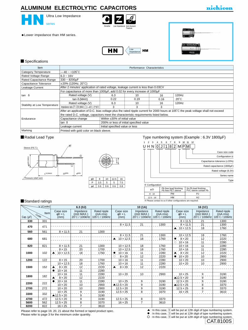
CAT.8100S
ALUMINUM ELECTROLYTIC CAPACITORS
HN series
Ultra Low Impedance
Lower impedance than HM series.
Approved by Reliability Center for ElectronicComponent, Japan-Certification No. RCJ-03-23C
Please refer to page 19, 20, 21 about the formed or taped product spec.Please refer to page 3 for the minimum order quantity.
HN HMLowImpedance
ltem Performance Characteristics
6.3 ~ 16V
±20% (120Hz, 20˚C)
After an application of D.C. bias voltage plus the rated ripple current for 2000 hours at 105˚C the peak voltage shall not exceed the rated D.C. voltage, capacitors meet the characteristic requirements listed below.
Leakage current lnitial specified value or less
Printed with gold color on black sleeve.
Rated Voltage Range
Rated Capacitance Range
Capacitance Tolerance
Leakage Current
Stability at Low Temperature
Endurance
Marking
Radial Lead Type Type numbering system (Example : 6.3V 1800µF)
Specifications
Rated voltage (V)
Rated voltage (V)tan δ (MAX)
6.3
6.33
0.2210
103
0.1916
163
0.16120Hz
120Hz20˚C
Impedance ratio ZT / Z20 (MAX.) Z—40˚C / Z+20˚C
Standard ratings
330
470
560
680
820
1000
1200
1500
1800
2200
2700
3300
470056008200
331
471
561
681
821
102
122
152
182
222
272
332
472562822
8 × 11.5
8 × 11.58 × 15
10 × 12.5
8 × 1510 × 12.58 × 20
10 × 1610 × 168 × 20
10 × 1610 × 2010 × 2010 × 25
12.5 × 2012.5 × 2012.5 × 25
16 × 25
21
212018
20181211111211101099987
1300
130017001760
17001760222022802280222022802900290031903190319033703610
Case sizeφD × L(mm)
Rated ripple(mA rms)
105˚C / 100kHz
Impedance(mΩ MAX.)
20˚C / 100kHz
6.3 (0J)
8 × 11.5
8 × 11.510 × 12.5
10 × 12.510 × 12.510 × 168 × 20
10 × 1610 × 168 × 20
10 × 20
10 × 2512.5 × 2012.5 × 2012.5 × 25
12.5 × 2516 × 25
21
2118
18181112111112
10
9998
87
1300
13001760
1760176022802220228022802220
2900
3190319031903370
33703610
Case sizeφD × L(mm)
Rated ripple(mA rms)
105˚C / 100kHz
Impedance(mΩ MAX.)
20˚C / 100kHz
10 (1A)V (Code)
ItemCap. (µF)
8 × 11.58 × 11.5
10 × 12.5
10 × 12.58 × 20
10 × 1610 × 1610 × 168 × 20
10 × 2010 × 2010 × 20
10 × 2512.5 × 2012.5 × 2012.5 × 2512.5 × 25
16 × 25
212118
181211111112101010
999887
130013001760
176022202280228022802220290029002900
319031903190337033703610
Case sizeφD × L(mm)
Rated ripple(mA rms)
105˚C / 100kHz
Impedance(mΩ MAX.)
20˚C / 100kHz
16 (1C)
Code
tan δ
φD
P
φd
8
3.5
0.6
10
5
0.6
12.5
5
0.6
16
7.5
0.8
P±0
.5
L+1.5MAX 15MIN 4MIN
φD± 0
.5M
AX
Pressure relief vent
φd U1
H2
N3
04
J5
16
87
28
M9
P10
M11 12
Configuration
Cace size code
Capacitance tolerance (±20%)
Rated capacitance (1800µF)
Rated voltage (6.3V)
Series name
Type
330 ~ 8200µF
After 2 minutes' application of rated voltage, leakage current is less than 0.03CV
tan δ 200% or less of initial specified value
Category Temperature —40 ~ +105˚C
For capacitance of more than 1000µF, add 0.02 for every increase of 1000µF
Capacitance change Within ±30% of initial value
: In this case, n will be put at 12th digit of type numbering system. : In this case, c will be put at 12th digit of type numbering system. : In this case, . will be put at 12th digit of type numbering system.
Sleeve (P.E.T.)
φ D
8 · 10
Pb free lead finishingPb free PET sleeve
Sn-Pb lead finishingPVC sleeve contain Pb
PM PJ
12.5 · 16 HM HJ
Configuration
Please contact to us if other configurations are required.
Sleeve : BLACK
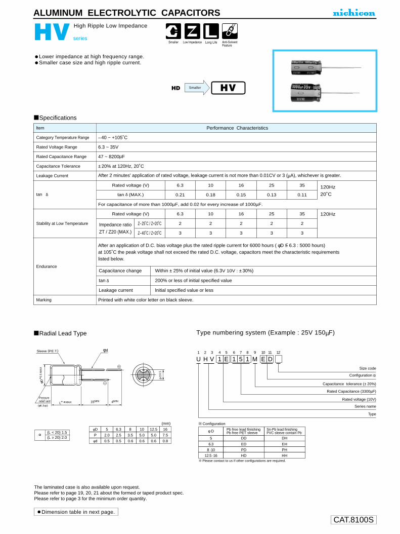
CAT.8100S
ALUMINUM ELECTROLYTIC CAPACITORS
HV series
High Ripple Low Impedance
Lower impedance at high frequency range.Smaller case size and high ripple current.
Specifications
HVHD
Approved by Reliability Center for ElectronicComponent, Japan-Certification No. RCJ-03-23C
Dimension table in next page.
Smaller
The laminated case is also available upon request.Please refer to page 19, 20, 21 about the formed or taped product spec.Please refer to page 3 for the minimum order quantity.
Radial Lead Type Type numbering system (Example : 25V 150µF)
U1
H2
V3
14
E5
16
57
18
M9
E10
D11 12
15MIN 4MIN
(mm)
φD
P
φd
10
5.0
0.6
5
2.0
0.5
12.5
5.0
16
7.5
0.6 0.8
6.3
2.5
0.5 0.6
8
3.5
Size code
Configuration
Series name
Type
Pressurerelief vent
φd
(φ6.3up)
φD+
0.5
MA
X
L+ MAX
Capacitance tolerance (± 20%)
Rated Capacitance (3300µF)
Rated voltage (10V)
(L < 20) 1.5(L 20) 2.0
φ D
5
Pb free lead finishingPb free PET sleeve
Sn-Pb lead finishingPVC sleeve contain Pb
DD DH
6.3 ED EH
8 ·10 PD PH
12.5 ·16 HD HH
Configuration
Sleeve (P.E.T.)
Please contact to us if other configurations are required.
P±0
.5
Performance Characteristicsltem
0.21 0.18 0.15 0.13 0.11
Category Temperature Range
Rated Voltage Range
Rated Capacitance Range
Capacitance Tolerance
Leakage Current
tan δ
Stability at Low Temperature
Endurance
Marking
–40 ~ +105˚C
6.3 ~ 35V
47 ~ 8200µF
±20% at 120Hz, 20˚C
After 2 minutes' application of rated voltage, leakage current is not more than 0.01CV or 3 (µA), whichever is greater.
Rated voltage (V)
Rated voltage (V)
tan δ (MAX.)
For capacitance of more than 1000µF, add 0.02 for every increase of 1000µF.
Z–25˚C / Z+20˚C
Z–40˚C / Z+20˚C
Impedance ratio
ZT / Z20 (MAX.)
6.3 10 16 25 35
2 2 2 2 2
3 3 3 3 3
6.3 10 16 25 35
After an application of D.C. bias voltage plus the rated ripple current for 6000 hours ( φD <= 6.3 : 5000 hours) at 105˚C the peak voltage shall not exceed the rated D.C. voltage, capacitors meet the characteristic requirementslisted below.
Printed with white color letter on black sleeve.
Capacitance change Within ± 25% of initial value (6.3V 10V : ±30%)
tan δ 200% or less of initial specified value
Leakage current lnitial specified value or less
120Hz
20˚C
120Hz

CAT.8100S
HVseries
ALUMINUM ELECTROLYTIC CAPACITORS
Standard ratings
100
150
220
330
470
680
820
1000
1200
1500
1800
2200
2700
3300
3900
4700
5600
6800
8200
101
151
221
331
471
681
821
102
122
152
182
222
272
332
392
472
562
682
822
5 × 11
6.3 × 11
6.3 × 11
8 × 11.5
8 × 11.5
10 × 12.5
10 × 12.5
8 × 15
8 × 20
10 × 16
10 × 20
10 × 25
12.5 × 20
12.5 × 20
12.5 × 25
12.5 × 31.5
12.5 × 35.5
16 × 20
16 × 25
0.23
0.10
0.10
0.059
0.059
0.043
0.043
0.046
0.031
0.030
0.019
0.017
0.016
0.016
0.014
0.012
0.011
0.014
0.012
0.76
0.33
0.33
0.181
0.181
0.133
0.133
0.143
0.105
0.095
0.057
0.051
0.041
0.041
0.036
0.031
0.029
0.036
0.033
360
460
550
900
990
1250
1360
1330
1550
1815
2160
2475
2500
2725
3190
3795
3925
3575
3990
5 × 11
6.3 × 11
6.3 × 11
8 × 11.5
8 × 11.5
10 × 12.5
10 × 12.5
8 × 15
10 × 16
10 × 16
8 × 20
10 × 20
10 × 25
12.5 × 20
12.5 × 20
12.5 × 25
12.5 × 31.5
16 × 20
12.5 × 35.5
16 × 25
0.23
0.10
0.10
0.059
0.059
0.043
0.043
0.046
0.030
0.030
0.031
0.019
0.017
0.016
0.016
0.014
0.012
0.014
0.011
0.012
0.76
0.33
0.33
0.181
0.181
0.133
0.133
0.143
0.095
0.095
0.105
0.057
0.051
0.041
0.041
0.036
0.031
0.036
0.029
0.033
360
450
550
820
990
1250
1360
1330
1650
1815
1550
2160
2475
2450
2725
3190
3795
3575
3925
3990
5 × 11
6.3 × 11
6.3 × 11
8 × 11.5
8 × 11.5
10 × 12.5
8 × 15
10 × 16
10 × 16
8 × 20
10 × 20
10 × 20
10 × 25
12.5 × 20
12.5 × 25
12.5 × 31.5
16 × 20
12.5 × 35.5
16 × 25
0.23
0.10
0.10
0.059
0.059
0.043
0.046
0.030
0.030
0.031
0.019
0.019
0.017
0.016
0.014
0.012
0.014
0.011
0.012
0.76
0.33
0.33
0.181
0.181
0.133
0.143
0.095
0.095
0.105
0.057
0.057
0.051
0.041
0.036
0.031
0.036
0.029
0.033
360
450
550
830
990
1360
1330
1650
1815
1550
1930
2160
2475
2725
3190
3795
3575
3925
3990
Cap.(µF)
V (Code) 6.3 (0J)
Case sizeφD × L(mm)
Case sizeφD × L(mm)
Case sizeφD × L(mm)
Impedance (Ω MAX.) Impedance (Ω MAX.) Impedance (Ω MAX.)
20˚C / 100kHz 20˚C / 100kHz 20˚C / 100kHz–10˚C / 100kHz –10˚C / 100kHz –10˚C / 100kHz
Rated ripple(mA rms)
105˚C / 100kHz
Rated ripple(mA rms)
105˚C / 100kHz
Rated ripple(mA rms)
105˚C / 100kHz
10 (1A) 16 (1A)
Item
Code
: In this case, will be put at 12th digit oftype numbering system.
6
120Hz 1kHz 10kHz 100kHz0.900.940.950.950.98
1.001.001.001.001.00
Cap.(µF)Frequency
Frequency coefficient of rated ripple current
47 ~ 150220 ~ 560680 ~ 1800
2200 ~ 39004700 ~ 8200
0.750.850.870.900.95
0.400.500.600.750.85
47
68
100
150
220
270
330
390
470
560
680
820
1000
1200
1500
1800
2200
2700
3300
470
680
101
151
221
271
331
391
471
561
681
821
102
122
152
182
222
272
332
5 × 11
6.3 × 11
6.3 × 11
8 × 11.5
8 × 11.5
8 × 11.5
8 × 15
10 × 12.5
8 × 20
10 × 16
10 × 20
10 × 25
12.5 × 20
12.5 × 20
12.5 × 25
12.5 × 31.5
16 × 20
12.5 × 35.5
16 × 25
0.23
0.10
0.10
0.059
0.059
0.059
0.046
0.043
0.031
0.030
0.019
0.017
0.016
0.016
0.014
0.012
0.014
0.011
0.012
0.76
0.33
0.33
0.181
0.181
0.181
0.143
0.133
0.105
0.095
0.057
0.051
0.041
0.041
0.036
0.031
0.036
0.029
0.033
360
450
550
810
900
990
1330
1360
1550
1815
2160
2475
2180
2725
3190
3795
3575
3925
3990
5 × 11
6.3 × 11
6.3 × 11
8 × 11.5
8 × 11.5
8 × 15
10 × 12.5
8 × 20
10 × 16
10 × 20
10 × 25
12.5 × 20
12.5 × 20
12.5 × 25
12.5 × 31.5
16 × 20
12.5 × 35.5
16 × 25
0.23
0.10
0.10
0.059
0.059
0.046
0.043
0.031
0.030
0.019
0.017
0.016
0.016
0.014
0.012
0.014
0.011
0.012
0.76
0.33
0.33
0.181
0.181
0.143
0.133
0.105
0.095
0.057
0.051
0.041
0.041
0.036
0.031
0.036
0.029
0.033
360
450
550
820
990
1330
1360
1550
1815
2160
2475
2725
2920
3190
3795
3575
3925
3990
Cap.(µF)
V (Code) 25 (1E)
Case sizeφD × L(mm)
Impedance (Ω MAX.)
20˚C / 100kHz –10˚C / 100kHz
Rated ripple(mA rms)
105˚C / 100kHz
35 (1V)
Case sizeφD × L(mm)
Impedance (Ω MAX.)
20˚C / 100kHz –10˚C / 100kHz
Rated ripple(mA rms)
105˚C / 100kHzItem
Code

CAT.8100S
ALUMINUM ELECTROLYTIC CAPACITORS
HZ series
Ultra Low Impedance
Lower impedance than HN series.
Please refer to page 19, 20, 21 about the formed or taped product spec.Please refer to page 3 for the minimum order quantity.
HZ HNLowImpedance
ltem Performance Characteristics
6.3 ~ 16V
±20% (120Hz, 20˚C)
After an application of D.C. bias voltage plus the rated ripple current for 2000 hours at 105˚C the peak voltage shall not exceed the rated D.C. voltage, capacitors meet the characteristic requirements listed below.
Leakage current lnitial specified value or less
Printed with gold color on black sleeve.
Rated Voltage Range
Rated Capacitance Range
Capacitance Tolerance
Leakage Current
Stability at Low Temperature
Endurance
Marking
Radial Lead Type Type numbering system (Example : 6.3V 1800µF)
Specifications
Rated voltage (V)
Rated voltage (V)tan δ (MAX)
6.3
6.3
3
0.22
10
10
3
0.19
16
16
3
0.16
120Hz
120Hz
20˚C
Impedance ratio ZT / Z20 (MAX.) Z—40˚C / Z+20˚C
Standard ratings
470
680
820
1000
1200
1500
1800
2200
27003300
471
681
821
102
122
152
182
222
272332
8 × 11.510 × 12.5
8 × 1510 × 12.58 × 20
10 × 1810 × 168 × 20
10 × 1610 × 2010 × 2010 × 25
1412
14129101091077
6.5
22102280
2210228028802960296028802960377037704690
Case sizeφD × L(mm)
Rated ripple(mA rms)
105˚C / 100kHz
Impedance(mΩ MAX.)
20˚C / 100kHz
6.3 (0J)
10 × 12.5
10 × 12.510 × 12.510 × 168 × 20
10 × 1610 × 168 × 20
10 × 20
10 × 25
12
121210910109
7
6.5
2288
2280228029602880296029602880
3770
4140
Case sizeφD × L(mm)
Rated ripple(mA rms)
105˚C / 100kHz
Impedance(mΩ MAX.)
20˚C / 100kHz
10 (1A)V (Code)
ItemCap. (µF)
10× 12.510× 12.58× 20
10× 1610× 1610× 168× 20
10× 2010× 2010× 20
10× 25
121291010109777
6.5
2280228028802960296029602880377037703770
4140
Case sizeφD × L(mm)
Rated ripple(mA rms)
105˚C / 100kHz
Impedance(mΩ MAX.)
20˚C / 100kHz
16 (1C)
Code
tan δ
φD
P
φd
8
3.5
0.6
10
5
0.6
P±0
.5
L+1.5MAX 15MIN 4MIN
φD± 0
.5M
AX
Pressure relief vent
φd U1
H2
Z3
04
J5
16
87
28
M9
P10
M11 12
Configuration
Cace size code
Capacitance tolerance (±20%)
Rated capacitance (1800µF)
Rated voltage (6.3V)
Series name
Type
470 ~ 3300µF
After 2 minutes' application of rated voltage, leakage current is less than 0.03CV
tan δ 200% or less of initial specified value
Category Temperature –40 ~ +105˚C
For capacitance of more than 1000µF, add 0.02 for every increase of 1000µF
Capacitance change Within ±30% of initial value
: In this case, n will be put at 12th digit of type numbering system. : In this case, c will be put at 12th digit of type numbering system. : In this case, . will be put at 12th digit of type numbering system.
Sleeve (P.E.T.)
φ D
8
Pb free lead finishingPb free PET sleeve
Sn-Pb lead finishingPVC sleeve contain Pb
PM PJ
10 PM PJ
Configuration
Please contact to us if other configurations are required.

CAT.8100S
ALUMINUM ELECTROLYTIC CAPACITORS
JB series
Memory Back-Up Use
Developed for memory back-up, with load life of 1000 hours at +85°C.Superior to electric double layer type capacitors in the following characteristics::•Better voltage maintenance.•Speedier charge-up available due to low impedance feature.•Wider operating temperature range of –25 ~ +85°C.
Radial Lead Type
Specifications
Type numbering system (Example : 5.5V 10mF)
U1
J2
B3
04
L5
16
07
38
T9
H10
D11
ConfigurationCapacitance tolerance
(–10 ~ +50%)
Rated Capacitance (10mF)
Rated voltage (5.5V)
Series name
TypeL+ MAX 15MIN 4MIN
φd
φD+
0.5
MA
X
P±0
.5
φD
P
φd
10
5.0
0.6
12.5
5.0
0.6
16
7.5
0.8
18
7.5
0.8
Pressurerelief vent
Sleeve (P.E.T.)
φ D
10
Pb free lead finishingPb free PET sleeve
Sn-Pb lead finishingPVC sleeve contain Pb
PD PA
HA12.5 ~ 18 HD
Configuration
Please contact to us if other configurations are required.
Category Temperature Range
Rated Voltage Range
Rated Capacitance Range
Capacitance Tolerance
Leakage Current
Voltage Maintenance
StabiIity at Low Temperature
Impedance See Note 4
Endurance
Performance CharacteristicsItem
–25 ~ +85°C
5.5V
2.2 ~ 47mF See Note 1
–10 ~ +50%
C (µA) (C = Rated capacitance value in mF) See Note 2
More than 3.5V See Note 3
Capacitance (–25°C) / Capacitance (20°C) × 100 70%
Capacitance change
Leakage current
Voltage maintenance
After 1000 hours' application of rated voltageat 85°C, capacitors meet the characteristicrequirements listed at right.
Shelf LifeAfter leaveing capacitors under no load at 85°C for 500 hours, they meet the requirementsfor endurance characteristics listed above.
Marking Printed with white color letter on black sleeve.
ImpedanceWithin ±30% of initial value
Initial specified value or lessSatisfies intial specified value
Within 4 times of initial specified value
Capacitance (mF)
Impedance (Ω)
2.21.5
3.31.0
4.70.6
8.20.3
100.3
180.2
220.2
270.2
330.2
390.1
470.1
Note :1. After charging a capacitor at the rated voltage of 5.5V for an hour, the capacitance is
calculated by the following formula, measuring the time of duration, ∆T (Sec.) from4V down to 3V when constant current dischage at i (mA) = 0.02 × nominal capacitanceis carried out.
Capacitance (mF) = i × ∆T2. Current value (20°C) after applying the rated voltage of 5.5V for an hour.3. Voltage value maintained after the capacitor is subjected to 1 hour voltage application
at 5V and then left at room temperature (lower than 25°C) for 24 hours.4. Measuring Frequency : 1kHz (20°C)
Ratings (V—mF) Case Size φD × L (mm)
5.5 —2.2 10 × 12.5
5.5 —3.3 10 × 16
5.5 —4.7 10 × 20
5.5 —8.2 12.5 × 20
5.5 —10 12.5 × 25
5.5 —18 16 × 25
5.5 —22 16 × 31.5
5.5 —27 16 × 35.5
5.5 —33 18 × 31.5
5.5 —39 18 × 35.5
5.5 —47 18 × 40
α(L < 20) 1.5
(L 20) 2.0
Dimensions
Please refer to page 19, 20, 21 about the formed or taped product spec.Please refer to page 3 for the minimum order quantity.
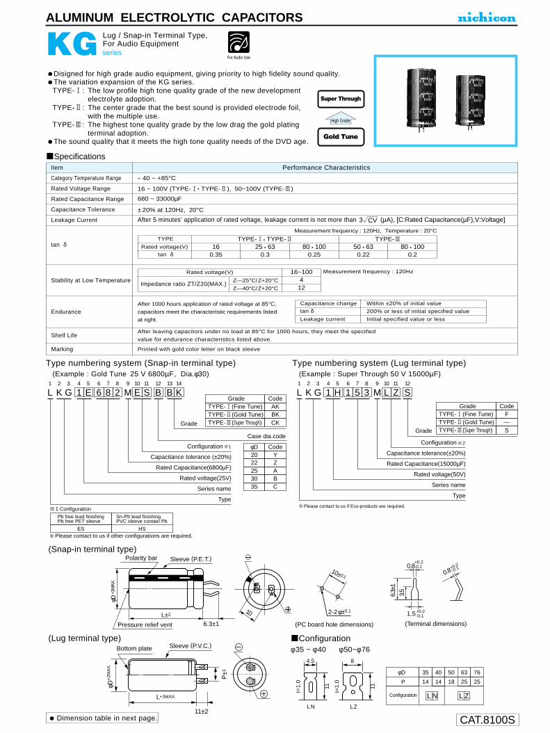
CAT.8100S
ALUMINUM ELECTROLYTIC CAPACITORS
KG series
Lug / Snap-in Terminal Type,For Audio Equipment
Disigned for high grade audio equipment, giving priority to high fidelity sound quality.The variation expansion of the KG series.TYPE-1: The low profile high tone quality grade of the new development
electrolyte adoption.TYPE-2: The center grade that the best sound is provided electrode foil,
with the multiple use.TYPE-3: The highest tone quality grade by the low drag the gold plating
terminal adoption.The sound quality that it meets the high tone quality needs of the DVD age.
Specifications
Category Temperature Range
Rated Voltage Range
Rated Capacitance Range
Capacitance Tolerance
Leakage Current
tan δ
Stability at Low Temperature
Shelf Life
Marking
Performance CharacteristicsItem
– 40 ~ +85°C
16 ~ 100V (TYPE-1• TYPE-2), 50~100V (TYPE-3)
680 ~ 33000µF
±20% at 120Hz, 20°C
After 5 minutes' application of rated voltage, leakage current is not more than (µA), [C:Rated Capacitance(µF),V:Voltage]
Printed with gold color letter on black sleeve
Measurement frequency : 120Hz
After 1000 hours application of rated voltage at 85°C,
capacitors meet the characteristic requirements listed
at right.
After leaving capacitors under no load at 85°C for 1000 hours, they meet the specified
value for endurance characteristics listed above.
Z—25°C/Z+20°C
Z—40°C/Z+20°C
Rated voltage(V)
Impedance ratio ZT/Z20(MAX.)
16~100412
Type numbering system (Snap-in terminal type)(Example : Gold Tune 25 V 6800µF, Dia.φ30)
Type numbering system (Lug terminal type)(Example : Super Through 50 V 15000µF)
High Grade
L1
G2
K3
14
H5
16
57
38
M9
L10
Z11
S12
Configuration
Grade
Capacitance tolerance(±20%)
Rated Capacitance(15000µF)
Rated voltage(50V)
Series name
Type
L1
G2
K3
14
E5
66
87
28
M9
E10
S11
B12
Configuration
Case dia.code
Capacitance tolerance (±20%)
Rated Capacitance(6800µF)
Rated voltage(25V)
Series name
K13
B14
Grade
Type
φD20
25
CodeY
22 Z
GradeTYPE-1(Fine Tune)TYPE-2(Gold Tune)TYPE-3(Super Through)
CodeAKBKCK
GradeTYPE-1(Fine Tune)TYPE-2(Gold Tune)TYPE-3(Super Through)
CodeF—S
A3035
BC
12
Pb free lead finishingPb free PET sleeve
Sn-Pb lead finishingPVC sleeve contain Pb
ES HS
Configuration
Please contact to us if other configurations are required.
1 Please contact to us if Eco-products are required.
Measurement frequency : 120Hz, Temperature : 20°C
TYPE
Rated voltage(V)tan δ
TYPE-3TYPE-1• TYPE-2
Endurance
Dimension table in next page.
Capacitance change
Leakage current
tan δWithin ±20% of initial value
Initial specified value or less
200% or less of initial specified value
16 25 • 630.30.35
80 • 100 50 • 630.220.25
80 • 1000.2
Gold Tune
Super Through
3 CV
(Snap-in terminal type)
(Lug terminal type) Configurationφ35 ~ φ40 φ50~φ76
10±0.1
2-2φ±0.1
(PC board hole dimensions) (Terminal dimensions)
6.3±
13.
5
1.5
0.8
+0.2-0.1
+0.2-0.10.8
+0.2-0.1
φD
P
35
14
40
14
50
18
63
25
76
25
L N L ZConfiguration
Bottom plate
L+3MAX.
φD+
2MA
X.
11±2
P±1
t=1.
0
11 11
t=1.
0
4.5 8
LN LZ
10
Polarity bar
L±2
φD +1
MAX
.
6.3±1Pressure relief vent
Sleeve (P.E.T.)
Sleeve (P.V.C.)

CAT.8100S
Dimensions (Snap-in Terminal Type : Gold Tune )
KG series
ALUMINUM ELECTROLYTIC CAPACITORS
D × L (mm)
820
1000
1200
1500
1800
2200
2700
3300
3900
4700
5600
6800
8200
10000
12000
15000
18000
22000
27000
33000
821
102
122
152
182
222
272
332
392
472
562
682
822
103
123
153
183
223
273
333
TYPE- 2
TYPE- 2
TYPE- 2
TYPE- 1
TYPE- 2
TYPE- 1
TYPE- 2
TYPE- 1
TYPE- 2
TYPE- 1
TYPE- 2
TYPE- 1
TYPE- 2
TYPE- 1
TYPE- 2
TYPE- 1
TYPE- 2
TYPE- 1
TYPE- 2
TYPE- I
TYPE- 2
TYPE- 1
TYPE- 2
TYPE- 1
TYPE- 2
TYPE- 1
TYPE- 2
TYPE- 1
TYPE- 2
TYPE- 1
TYPE- 2
TYPE- 1
TYPE- 2
TYPE- 1
TYPE- 2
TYPE- 1
TYPE- 2
20 × 25
1.55
20 × 30
1.75
20 × 25
1.45
20 × 35
2.20
20 × 30
1.90
20 × 40
2.40
20 × 35
2.05
20 × 50
2.65
20 × 40
2.25
20 × 45
2.60
22 × 20
1.50
22 × 20
1.35
22 × 25
1.75
22 × 30
2.20
22 × 25
1.90
22 × 35
2.40
22 × 30
2.05
22 × 40
2.65
22 × 35
2.20
22 × 50
2.75
22 × 40
2.50
22 × 45
2.80
25 × 20
1.55
25 × 20
1.70
25 × 25
2.15
25 × 30
2.30
25 × 25
2.00
25 × 35
2.45
25 × 30
2.15
25 × 40
2.75
25 × 35
2.40
25 × 45
3.10
25 × 40
2.60
25 × 50
3.50
25 × 45
2.95
25 × 50
3.40
30 × 20
1.85
30 × 20
2.10
30 × 25
2.50
30 × 30
2.75
30 × 25
2.50
30 × 35
3.10
30 × 30
2.65
30 × 40
3.40
30 × 35
2.90
30 × 45
3.80
30 × 40
3.25
30 × 50
4.25
30 × 45
3.70
35 × 20
2.25
35 × 20
2.10
35 × 25
2.60
35 × 30
3.45
35 × 25
2.90
35 × 35
3.80
35 × 30
3.35
35 × 40
4.25
35 × 35
3.65
35 × 45
4.50
35 × 20
2.20
35 × 20
2.25
35 × 25
3.05
35 × 30
3.30
35 × 25
2.65
35 × 35
3.50
35 × 40
4.00
35 × 30
3.50
35 × 45
4.45
35 × 35
3.85
35 × 40
4.30
35 × 45
4.85
20×25
1.50
20 × 30
1.70
20 × 35
1.80
20 × 25
1.60
20 × 30
1.70
20 × 45
2.30
20 × 50
2.50
20 × 35
2.20
20 × 40
2.40
20 × 50
2.55
22 × 20
1.40
22 × 25
1.70
22 × 20
1.50
22 × 30
1.80
22 × 25
1.70
22 × 35
2.30
22 × 40
2.50
22 × 30
2.20
22 × 50
2.65
22 × 35
2.35
22 × 40
2.65
22 × 45
2.90
25 × 20
1.50
25 × 20
1.55
25 × 25
2.10
25 × 30
2.25
25 × 35
2.40
25 × 25
2.15
25 × 40
2.65
25 × 30
2.30
25 × 45
2.90
25 × 35
2.50
25 × 50
3.30
25 × 40
2.75
25 × 45
3.15
25 × 50
3.55
30 × 20
1.85
30 × 20
1.85
30 × 25
2.50
30 × 30
2.65
30 × 35
2.85
30 × 25
2.65
30 × 40
3.30
30 × 30
2.80
30 × 45
3.55
30 × 35
3.10
30 × 50
4.15
30 × 40
3.40
30 × 45
3.85
20 × 25
1.40
20 × 30
1.75
20 × 25
1.60
20 × 35
2.05
20 × 30
1.75
20 × 40
2.25
20 × 45
2.40
20 × 35
2.20
20 × 40
2.40
20 × 50
2.50
20×25
1.50
20×30
1.65
20×35
1.80
20×25
1.70
20×30
1.85
20×45
2.35
20×35
2.00
20×50
2.45
20 × 40
2.25
20 × 45
2.45
20 × 50
2.75
22 × 20
1.30
22 × 25
1.55
22 × 20
1.45
22 × 30
2.05
22 × 25
1.75
22 × 35
2.25
22 × 40
2.40
22 × 30
2.20
22 × 45
2.70
22 × 35
2.35
22 × 50
3.00
22 × 40
2.60
22 × 45
2.90
25 × 20
1.70
25 × 20
1.55
25 × 25
2.00
25 × 30
2.20
25 × 35
2.30
25 × 25
2.15
25 × 30
2.25
25 × 40
3.00
25 × 50
3.10
25 × 40
2.70
25 × 45
3.05
25 × 50
3.45
30 × 20
2.05
30 × 20
1.85
30 × 25
2.40
30 × 30
2.55
30 × 25
2.60
30 × 35
3.30
30 × 30
2.75
30 × 40
3.60
30 × 35
3.00
30 × 50
3.80
30 × 40
3.30
30 × 45
3.80
30 × 50
4.30
35 × 20
2.50
35 × 20
2.25
35 × 25
2.85
35 × 30
3.05
35 × 35
3.30
35 × 25
3.20
35 × 40
3.70
35 × 30
3.40
35 × 45
4.10
35 × 35
3.80
35 × 50
4.80
35 × 40
4.15
35 × 45
4.70
22 × 20
1.00
22 × 25
1.65
22 × 20
1.55
22 × 30
1.80
22 ×25
1.85
22 × 35
2.35
22 × 30
2.00
22 × 45
2.45
22 × 35
2.20
22 × 50
2.80
22 × 40
2.35
22 × 45
2.60
22 × 50
2.90
25 × 20
1.50
25 × 20
1.65
25 × 25
2.15
25 × 30
2.30
25 × 25
1.95
25 × 35
2.50
25 × 40
2.80
25 × 30
2.50
25 × 45
3.00
25 × 35
2.70
25 × 50
3.40
25 × 40
2.90
25 × 45
3.30
30 × 20
1.80
30 × 20
2.05
30 × 25
2.60
30 × 30
2.80
30 × 25
2.35
30 × 35
3.00
30 × 40
3.30
30 × 30
3.00
30 × 45
3.60
30 × 35
3.25
30 × 50
4.10
30 × 40
3.55
30 × 45
4.00
35 × 20
2.25
35 × 20
2.45
35 × 25
3.15
35 × 30
3.35
35 × 25
2.85
35 × 35
3.60
35 × 40
3.95
35 × 30
3.65
35 × 45
4.40
35 × 35
4.00
35 × 50
5.05
35 × 40
4.35
35 × 50
4.70
Case
size
φ20 φ22 φ25
16V (1C)
φ30 φ35 φ20 φ22 φ25
25V (1E)
φ30 φ35 φ20 φ22 φ25
35V (1V)
φ30 φ35 φ20 φ22 φ25
50V (1H)
φ30 φ35Code GradeCap.(µF)
Rated ripple (A rms) at 85°C 120 Hz

CAT.8100S
KG series
ALUMINUM ELECTROLYTIC CAPACITORS
D × L (mm)
D × L (mm)Dimensions (Snap-in Terminal Type : Gold Tune)
Dimensions (Lug Terminal Type : Gold Tune, Super Through)
Rated ripple (A rms) at 85°C 120 Hz
Rated ripple (A rms) at 85°C 120 Hz
680
820
1000
1200
1500
1800
2200
2700
3300
3900
4700
5600
6800
8200
10000
681
821
102
122
152
182
222
272
332
392
472
562
682
822
103
TYPE- 1
TYPE- 2
TYPE- 3
TYPE- 1
TYPE- 2
TYPE- 3
TYPE- 1
TYPE- 2
TYPE- 3
TYPE- 1
TYPE- 2
TYPE- 3
TYPE- 1
TYPE- 2
TYPE- 3
TYPE- 1
TYPE- 2
TYPE- 3
TYPE- 1
TYPE- 2
TYPE- 3
TYPE- 1
TYPE- 2
TYPE- 3
TYPE- 1
TYPE- 2
TYPE- 3
TYPE- 1
TYPE- 2
TYPE- 3
TYPE- 1
TYPE- 2
TYPE- 3
TYPE- 1
TYPE- 2
TYPE- 1
TYPE- 2
TYPE- 1
TYPE- 1
φ20 φ22 φ2563V (1J)
φ30 φ35 φ20 φ22 φ2580V (1K)
φ30 φ35 φ20 φ22 φ25100V (2A)
φ30 φ35CodeCap.(µF) Grade
20 × 301.75
20 × 251.65
20 × 351.90
20 × 251.45
20 × 301.85
20 × 402.10
20 × 351.95
20 × 452.35
20 × 301.90
20 × 402.15
20 × 352.05
20 × 452.35
20 × 402.25
20 × 502.40
22 × 251.75
22 × 201.30
22 × 301.90
22 × 251.85
22 × 352.05
22 × 301.95
22 × 402.25
22 × 251.90
22 × 352.15
22 × 452.60
22 × 302.00
22×402.35
22 × 502.90
22 × 352.20
22 × 452.70
22 × 402.45
22 × 452.80
25 × 201.65
25 × 251.85
25 × 302.00
25 × 201.65
25 × 251.90
25 × 302.10
25 × 352.65
25 × 252.00
25 × 402.90
25 × 302.15
25 × 352.75
25 × 453.25
25 × 352.35
25 × 452.80
25 × 402.60
25 × 503.20
25 × 452.85
25 × 503.20
30 × 201.90
30 × 201.95
30 × 252.20
30 × 202.05
30 × 252.35
30 × 302.90
30 × 302.50
30 × 353.20
30 × 252.50
30 × 352.75
30 × 453.30
30×302.70
30 × 403.20
30 × 503.80
30 × 352.85
30 × 453.35
30 × 403.10
30 × 503.80
30 × 453.45
30×503.90
35 × 202.30
35 × 202.45
35 × 252.75
35×202.10
35 × 252.95
35 × 303.65
35 × 303.15
35 × 354.00
35 × 253.00
35 × 353.35
35 × 404.30
35 × 303.20
35 × 504.50
35 × 353.40
35 × 404.35
35 × 403.75
35 × 504.60
35 × 454.20
35 × 504.80
20 × 452.10
20 × 251.70
20 × 352.05
20 × 502.40
20 × 301.80
20 × 452.20
20 × 351.95
20 × 502.45
20 × 402.20
20 × 452.45
22 × 352.25
22 × 302.05
22 × 402.45
22 × 251.85
22 × 352.20
22 × 502.60
22 × 301.95
22 × 402.45
22 × 352.15
22 × 502.60
22 × 402.35
22 × 452.70
25 × 302.15
25 × 201.65
25 × 252.00
25 × 352.35
25 × 302.15
25 × 402.60
25 × 251.90
25 × 352.30
25 × 452.85
25 × 302.10
25 × 402.65
25 × 503.30
25 × 452.85
25 × 352.75
25 × 503.25
25 × 503.25
30 × 202.05
30 × 252.40
30 × 302.60
30 × 202.00
30 × 252.40
30 × 352.80
30 × 302.65
30 × 403.20
30×252.40
30 × 352.85
30 × 453.55
30 × 302.55
30 × 403.15
30 × 504.05
30 × 352.80
30 × 453.60
30 × 403.15
30 × 504.10
30 × 453.45
30 × 453.85
35 × 202.55
35 × 202.10
35 × 252.95
35 × 303.25
35 × 202.50
35 × 253.00
35 × 353.50
35 × 303.25
35 × 403.90
35 × 253.00
35 × 353.55
35 × 454.45
35 × 303.20
35 × 403.95
35 × 505.05
35 × 353.40
35 × 454.35
35 × 403.75
35 × 504.85
35 × 454.10
35 × 504.65
20 × 301.70
20 × 402.15
20 × 351.85
20 × 452.40
20 × 402.05
20 × 452.30
20 × 502.65
22 × 251.75
22 × 352.15
22 × 452.65
22 × 301.85
22 × 402.40
22 × 503.00
22 × 452.70
22 × 402.20
22 × 503.00
22 × 452.55
22 × 502.85
25 × 302.10
25 × 352.70
25 × 251.80
25 × 403.00
25 × 352.75
25 × 503.10
25 × 302.35
25 × 402.75
25 × 352.60
25 × 503.20
25 × 402.85
25 × 453.20
30 × 201.90
30 × 252.35
30 × 303.00
30 × 353.30
30 × 252.20
30 × 303.05
30×403.60
30 × 353.40
30 × 503.90
30 × 302.90
30 × 403.70
30 × 353.20
30 × 503.95
30 × 403.55
30 × 503.75
35 × 202.45
35 × 252.85
35 × 303.05
35 × 202.30
35 × 252.90
35 × 353.30
35 × 303.20
35 × 403.75
35 × 252.75
35 × 353.40
35×454.15
35 × 303.00
35 × 403.80
35 × 504.75
35×353.25
35 × 454.30
35 × 504.95
35 × 404.30
35 × 504.50
Case sizeRated
6800
10000
15000
22000
682
103
153
223
TYPE- 1
TYPE- 2
TYPE- 3
TYPE- 1
TYPE- 2
TYPE- 3
TYPE- 1
TYPE- 2
TYPE- 3
TYPE- 1
TYPE- 2
TYPE- 3
50 (1H) 63 (1J) 80 (1K) 100 (2A)CodeCap.(µF) Grade
40 × 80
35 × 80 40 × 100
40 × 80 50 × 10040 × 6850 × 8063 × 80
5.5
4.66.1
6.18.45.48.3
10.5
35 × 68 40 × 100
40 ×8050 × 8040 × 68
40 × 10063 × 80
40 × 100 50 × 100 63 × 100
4.36.1
4.96.25.66.78.76.69.111.6
40 × 10050 × 8040 × 6850 × 8063 × 80
40 × 100 50 × 100 63 × 100 50 × 100 63 × 100 76 × 100
6.16.75.46.27.66.58.4
10.17.811.613.7
40 × 6850 × 80
50 × 100 40 × 100 50 × 100 63 × 100 50 × 10063 × 80
76 × 10063 × 80
76 × 100Case size
5.16.27.36.06.98.37.48.711.39.712.9
Ratedripple

CAT.8100S
ALUMINUM ELECTROLYTIC CAPACITORS
KL series
Low Leakage Current
Standard low leakage current series.
Radial Lead Type
Specifications
Category Temperature Range
Rated Voltage Range
Rated Capacitance Range
Capacitance Tolerance
Leakage Current
tan δ
stability at Low Temperature
Endurance
Performance CharacteristicsItem
–40 ~ +85°C ( –40 ~ +105°C product also available upon request, but product rated at up to 50V less than or equal to φ10 × 12.5 Lmm)
6.3 ~ 100V
0.1 ~ 10000µF
±20% (M), ±10% (K) at 120Hz 20°C
After 1 minute's (for case size 10 × 12.5 or smaller) or 2 minute's (for case size 10 × 16 or larger) application of rated voltage,leakage current is not more than 0.002CV or 0.2 (µA) whichever is greater.
Measurement frequency : 120Hz, Temperature : 20°C
Measurement frequency : 120Hz
Values in ( ) applicable to
φ10 × 16 or larger case size.
Capacitance change
Leakage current
After 2000 hours' application of rated voltageat 85°C, or 1000 hours' at 105°C, capacitorsmeet the characteristics requirements listedat right.
Shelf LifeAfter leaving capacitors under no load at 85°C for 1000 hours, they meet the specifiedvalue for endurance characteristics listed above.
Marking Printed with white color letter on black sleeve. (PVC sleeve product : Printed with black color letter on orange sleeve.)
tan δWithin ±15% of initial value (6.3V : Within ±20%)
Initial specified value or less150% or less of initial specified value
Type numbering system (Example : 10V 47µF)
KL VR
Z–25°C / Z+20°C
Z–40°C / Z+20°C
Rated voltage (V)
Impedance ratio
ZT / Z20 (MAX.)
6.33 (4) 5 (8)
102 (3) 4 (6)
162
3 (4)
251.5
2 (4)
351.5
2 (3)
501.5
2 (3)
631.5
2 (3)
1001.5
2 (3)
U1
K2
L3
14
A5
46
77
08
M9
D10
D11
ConfigurationCapacitance tolerance (M : ±20%, K : ±10%)
Rated Capacitance (47µF)
Rated voltage (10V)
Series nameType
A12
N13
A14
In case 105°C unit is required
φ D
5
Pb free lead finishingPb free PET sleeve
Sn-Pb lead finishingPVC sleeve contain Pb
DD DA
6.3 ED EA
8 · 10 PD PA
12.5 ~ 18 HD HA
Configuration
2
2
1
1
Please contact to us if other configurations are required.
Pressurerelief vent
φD
P
5
2.0
6.3
2.5
8
3.5
10
5.0
12.5
5.0
16
7.5
18
7.5
φd 0.5 0.5 0.6 0.6 0.6 0.8 0.8
(~ φ10 × 12.5) 1.0 (φ10 × 16 ~) 1.5
L+ MAX (φ6.3up ) 15MIN 4MIN
φd
φD+
0.5
MA
X
P±0
.5
(mm)
Sleeve (P.E.T.)
Dimension table in next page.
For capacitance of more than 1000µF, add 0.02 for every increace of 1000µF.
~φ10 × 12.5φ10 × 16 ~
Rated voltage (V)
tan δ (MAX.)
6.30.180.21
100.150.17
160.120.14
250.080.12
350.080.12
500.080.10
630.070.08
1000.070.08
Low LeakageCurrent
Please refer to page 19, 20, 21 about the formed or taped product spec.Please refer to page 3 for the minimum order quantity.
Frequency coefficient of rated ripple currentFrequency
Cap.(µF)
~ 68
100 ~ 680
1000 ~ 10000
50Hz
0.75
0.80
0.85
120Hz
1.00
1.00
1.00
300Hz
1.35
1.23
1.10
1kHz
1.57
1.34
1.13
10kHz ~
2.00
1.50
1.15

CAT.8100S
KL series
ALUMINUM ELECTROLYTIC CAPACITORS
DimensionsV
CodeCap.(µF)
D × L (mm)
Rated Ripple (mA rms) at 85°C 120Hz
4.76.8
101522334768
100150220330470680
100015002200330047006800
10000
6.30J
10 × 12.510 × 1610 × 20
12.5 × 2512.5 × 25
16 × 2516 × 31.518 × 35.518 × 40
390480650910
10601270150017601900
101A
5 × 116.3 × 116.3 × 11
8 × 11.58 × 11.5
10 × 12.510 × 1610 × 20
12.5 × 2012.5 × 25
16 × 2516 × 31.516 × 35.518 × 35.5
110150180250310400530600810
10201200142016501890
161C
5 × 115 × 115 × 115 × 11
6.3 × 116.3 × 11
8 × 11.58 × 11.5
10 × 12.510 × 1610 × 20
12.5 × 2012.5 × 25
16 × 2516 × 2516 × 35.518 × 35.5
557085
100140160230280370420550730910
1150130015501820
251E
5 × 115 × 115 × 115 × 115 × 11
6.3 × 116.3 × 11
8 × 11.58 × 11.5
10 × 12.510 × 1610 × 20
12.5 × 2012.5 × 25
16 × 2516 × 31.516 × 35.518 × 40
45557085
100140170230280370400490660810
1010127014401720
4R76R8100150220330470680101151221331471681102152222332472682103
V
CodeCap.(µF)
0.10.150.220.330.470.6811.52.23.34.76.8
101522334768
100150220330470680
100015002200
351V
5 × 116.3 × 116.3 × 11
8 × 11.58 × 11.5
10 × 12.510 × 1610 × 20
12.5 × 2012.5 × 25
16 × 2516 × 2516 × 35.518 × 35.5
85110140190230300400440550680840
110013901580
501H
5 × 115 × 115 × 115 × 115 × 115 × 115 × 115 × 115 × 115 × 115 × 115 × 115 × 11
6.3 × 116.3 × 11
8 × 11.58 × 11.5
10 × 12.510 × 1610 × 20
12.5 × 2012.5 × 20
16 × 2516 × 2516 × 31.518 × 40
1.11.62.33.55.07.3
10.716234045557095
110165190250320420490600760910
11401480
631J
5 × 116.3 × 116.3 × 11
8 × 11.58 × 11.5
10 × 12.510 × 1610 × 20
12.5 × 2012.5 × 2012.5 × 25
16 × 2516 × 31.518 × 35.5
5975
100115170200270330450550710850
10501330
1002A
5 × 115 × 115 × 115 × 115 × 115 × 115 × 115 × 115 × 115 × 115 × 11
6.3 × 118 × 11.58 × 11.5
10 × 12.510 × 1610 × 2010 × 20
12.5 × 2012.5 × 25
16 × 2516 × 31.518 × 35.5
Case size
2.13.24.77.0
10.114.519232845506590
110136180220290370470580730910
Rated ripple
0R1R15R22R33R47R680101R52R23R34R76R8100150220330470680101151221331471681102152222

CAT.8100S
ALUMINUM ELECTROLYTIC CAPACITORS
U1
K2
Z3
14
E5
16
07
18
M9
P10
B11
Configuration
Capacitance tolerance (±20%)
Rated Capacitance (100µF)
Rated voltage (25V)
Series name
Type
φD Code
8 • 10 PB
HB12.5 ~ 18
Please contact to us if Eco-Products are required.
Pressurerelief vent
φD
P
8
3.5
10
5.0
12.5
5.0
16
7.5
18
7.5
L+ MAX 15MIN 4MIN
Sleeve φ 0.8 tinned copper wire
φD+
0.5M
AX
P±0
.5
Premium grade “nichicon MUSE” acoustic series.Ideally suited for first class audio equipment where qualitative and quantitativecomfortableness is required.
Radial Lead Type Type numbering system (Example : 25V 100µF)
Specifications
Category Temperature Range
Rated Voltage Range
Rated Capacitance Range
Capacitance Tolerance
Leakage Current
tan δ
Stability at Low Temperature
Endurance
Shelf Life
Marking
Performance CharacteristicsItem
–40 ~ +85°C
25 ~ 100V
10 ~ 1000µF
±20% at 120Hz, 20°C
After 1 minute's application of rated voltage, leakage current is 0.01CV or less.
Printed with gold color letter on black sleeve.
After leaving capacitors under no load at 85°C for 1000 hours, they meet the specifiedvalue for endurance characteristics listed above.
KZ series
Premium Grade Type, For Audio Equipment
KZ High Grade
Dimensions D × L (mm)
tan δ (MAX.)
Measurement frequency : 120Hz
After 1000 hours' application of rated voltageat 85°C, capacitors meet the characteristicrequirements listed at right.
Rated voltage (V) 250.12
500.08
1000.07
Z–25°C / Z+20°C
Z–40°C / Z+20°C
Rated voltage (V)
Impedance ratioZT / Z20 (MAX.)
2524
5023
10023
Capacitance change
Leakage Current
tan δWithin ±20% of initial value150% or less of initial specified valueInitial specifed value or less
Measurement frequency : 120Hz, Temperature : 20°C
FG
25 50 1001E 1H 2A
8 × 11.5
8 × 11.510 × 12.510 × 16
12.5 × 2012.5 × 25
16 × 2516 × 35.5
8 × 11.510 × 12.510 × 16
12.5 × 2016 × 2516 × 31.516 × 35.518 × 40
10 × 1610 × 20
12.5 × 2016 × 2516 × 35.518 × 35.5
10 10022 22033 33047 470
1000 101220033004700
100000
221331471102
VCodeCap.(µF)
α(φD < 10) 1.0(φD 10) 1.5
Please refer to page 19, 20, 21 about the formed or taped product spec.Please refer to page 3 for the minimum order quantity.

CAT.8100S
After an application of DC voltage (in the range of ratedDC voltage even after over-lapping the specified ripplecurrent) for 2000 hours at 85°C, capacitors meet thecharacteristic requirements listed at right.
After leaving capacitors under no load at 85°Cfor 1000 hours, they meet the characteristic requirements listed at right.
Capacitance change
Leakage current
tan δWithin ±20% of initial value200% or less of initial specified valueInitial specified value or less
Capacitance change
Leakage current
tan δWithin ±20% of initial value200% or less of initial specified valueInitial specified value or less
Stability at Low Temperature
tan δ
Endurance
– 40 ~ + 85°C (160 ~ 250V), – 25 ~ + 85°C (400 ~ 450V)Category Temperaturer Range
ALUMINUM ELECTROLYTIC CAPACITORS
LN series
Snap-in Terminal Type, Ultra-Smaller-Sized
Withstanding 2000 hours application of ripple current at 85°C.One rank smaller case sized than LS series.
Specifications
Rated Voltage Range
Rated Capacitance Range
Capacitance Tolerance
Leakage Current
Marking Printed with white color letter on black sleeve.
160 ~ 450V
68 ~ 3900µF
±20% at 120Hz, 20°C
I (µA) (After 5 minutes' application of rated voltage) [C : Rated Capacitance (µF) V : Voltage(V)]
Measurement frequency : 120Hz350 ~ 450
8Z—25°C/Z+20°C
Rated voltage(V)
Impedance ratioZT/Z20 (MAX.)
160 ~ 250
4
(PC board hole dimensions) (Terminal dimensions)
10± 0.1
2-2φ±0.1
4.0±
0.5
2.5
1.5
0.8
+0.2-0.1
+0.2
-0.10.8+0.2
-0.1
Polarity bar
10L±2
φ D +1
MAX
.
4.0±0.5Pressure relief vent
Sleeve (P.E.T.)
Drawing
Dimension table in next page.
Type numbering system ( Example : 400V 180µF)
L1
L2
N3
24
G5
16
87
18
M9
E10
L11
A12
313
014
Configuration
Case length code
Case dia.code
Capacitance tolerane (±20%)
Rated Capacitance (180µF)
Rated voltage (400V)
Series name
Type
φD
22
25
30
Code
Z
20 Y
A
B
35 C
Pb free lead finishingPb free PET sleeve
Sn-Pb lead finishingPVC sleeve contain Pb
EL HL
Configuration
Please contact to us if other configurations are required.
1
1
LSSmaller
LN
Item Performance Characteristics
Shelf Life
3 CV
Minimum order quantity : 50pcs.
The other terminal is also available upon request.Please refer to page 197 for schematic of dimensions.
Measurement frequency : 120Hz, Temperature : 20°CRated voltage (V)
tan δ (MAX.)160 ~ 400
0.154500.20

CAT.8100S
LN series
ALUMINUM ELECTROLYTIC CAPACITORS
Dimensions
220270330
390
470
560
680
820
1000
1200
1500
1800
20 × 2522 × 2522 × 3022 × 3025 × 2522 × 3525 × 3022 × 4025 × 3030 × 2522 × 4525 × 3530 × 3022 × 5025 × 4030 × 3035 × 2525 × 5030 × 3535 × 3030 × 4035 × 3530 × 5035 × 4035 × 45
1230131017501910191021102110225022502250250025002500277027702770277033203320332038403840425042504550
0.150.150.150.150.150.150.150.150.150.150.150.150.150.150.150.150.150.150.150.150.150.150.150.150.15
0.700.770.860.930.931.021.021.121.121.121.231.231.231.351.351.351.351.501.501.501.641.641.831.832.01
LLN2E221MELY25LLN2E271MELZ25LLN2E331MELZ30LLN2E391MELZ30LLN2E391MELA25LLN2E471MELZ35LLN2E471MELA30LLN2E561MELZ40LLN2E561MELA30LLN2E561MELB25LLN2E681MELZ45LLN2E681MELA35LLN2E681MELB30LLN2E821MELZ50LLN2E821MELA40LLN2E821MELB30LLN2E821MELC25LLN2E102MELA50LLN2E102MELB35LLN2E102MELC30LLN2E122MELB40LLN2E122MELC35LLN2E152MELB50LLN2E152MELC40LLN2E182MELC45
250V (2E)
Ratedripple(mA)
tan δ Leakage Current(mA) Code
SizeφD × L(mm)
Cap.(µF)
390
470
560
680
820
1000
1200
1500
1800
2200
2700
33003900
20 × 2520 × 3022 × 2520 × 3022 × 2520 × 3522 × 3025 × 2520 × 4022 × 3525 × 3022 × 4025 × 3030 × 2522 × 4525 × 3530 × 3025 × 4530 × 3525 × 5030 × 3535 × 3030 × 4535 × 3530 × 5035 × 4035 × 4535 × 50
1190176017602250225025002500250027502750275030003000300032503250325037303730420042004200478047805450545057506000
0.150.150.150.150.150.150.150.150.150.150.150.150.150.150.150.150.150.150.150.150.150.150.150.150.150.150.150.15
0.740.820.820.890.890.980.980.981.081.081.081.201.201.201.311.311.311.461.461.601.601.601.771.771.971.972.172.36
LLN2C391MELY25LLN2C471MELY30LLN2C471MELZ25LLN2C561MELY30LLN2C561MELZ25LLN2C681MELY35LLN2C681MELZ30LLN2C681MELA25LLN2C821MELY40LLN2C821MELZ35LLN2C821MELA30LLN2C102MELZ40LLN2C102MELA30LLN2C102MELB25LLN2C122MELZ45LLN2C122MELA35LLN2C122MELB30LLN2C152MELA45LLN2C152MELB35LLN2C182MELA50LLN2C182MELB35LLN2C182MELC30LLN2C222MELB45LLN2C222MELC35LLN2C272MELB50LLN2C272MELC40LLN2C332MELC45LLN2C392MELC50
160V (2C)
Ratedripple(mA)
tan δ Leakage Current(mA) Code
SizeφD × L(mm)
Cap.(µF)
330
390
470
560
680
820
1000
1200
1500
1800
2200
2700
20 × 2520 × 3022 × 2520 × 3522 × 3025 × 2522 × 3025 × 2522 × 3525 × 3030 × 2522 × 4025 × 3530 × 2525 × 4030 × 3035 × 2525 × 4530 × 3535 × 3025 × 5030 × 4035 × 3030 × 4535 × 3530 × 5035 × 4035 × 50
1440166016802030197019502430243026802680268029302930293032503250325035003610357038703870387043204320492049205450
0.150.150.150.150.150.150.150.150.150.150.150.150.150.150.150.150.150.150.150.150.150.150.150.150.150.150.150.15
0.770.830.830.910.910.911.001.001.101.101.101.211.211.211.341.341.341.461.461.461.641.641.641.801.801.981.982.20
LLN2D331MELY25LLN2D391MELY30LLN2D391MELZ25LLN2D471MELY35LLN2D471MELZ30LLN2D471MELA25LLN2D561MELZ30LLN2D561MELA25LLN2D681MELZ35LLN2D681MELA30LLN2D681MELB25LLN2D821MELZ40LLN2D821MELA35LLN2D821MELB25LLN2D102MELA40LLN2D102MELB30LLN2D102MELC25LLN2D122MELA45LLN2D122MELB35LLN2D122MELC30LLN2D152MELA50LLN2D152MELB40LLN2D152MELC30LLN2D182MELB45LLN2D182MELC35LLN2D222MELB50LLN2D222MELC40LLN2D272MELC50
200V (2D)
Ratedripple(mA)
tan δ Leakage Current(mA) Code
SizeφD × L(mm)
Cap.(µF)
82100
120
150
180
220
270
330
390
470
560
680
820
20 × 2520 × 2520 × 3022 × 2520 × 3522 × 3025 × 2520 × 4022 × 3525 × 3022 × 4025 × 3030 × 2522 × 4525 × 3530 × 2522 × 5025 × 4030 × 3035 × 2525 × 4530 × 3535 × 3030 × 4035 × 3030 × 4535 × 3530 × 5035 × 4035 × 45
800940
1080108012101210121014501450145015801580158016701670167019001900190019002130213021302390239026902690296029603250
0.150.150.150.150.150.150.150.150.150.150.150.150.150.150.150.150.150.150.150.150.150.150.150.150.150.150.150.150.150.15
0.540.600.650.650.730.730.730.800.800.800.880.880.880.980.980.981.081.081.081.081.181.181.181.301.301.411.411.561.561.71
LLN2G820MELY25LLN2G101MELY25LLN2G121MELY30LLN2G121MELZ25LLN2G151MELY35LLN2G151MELZ30LLN2G151MELA25LLN2G181MELY40LLN2G181MELZ35LLN2G181MELA30LLN2G221MELZ40LLN2G221MELA30LLN2G221MELB25LLN2G271MELZ45LLN2G271MELA35LLN2G271MELB25LLN2G331MELZ50LLN2G331MELA40LLN2G331MELB30LLN2G331MELC25LLN2G391MELA45LLN2G391MELB35LLN2G391MELC30LLN2G471MELB40LLN2G471MELC30LLN2G561MELB45LLN2G561MELC35LLN2G681MELB50LLN2G681MELC40LLN2G821MELC45
400V (2G)Ratedripple(mA)
tan δ Leakage Current(mA) Code
SizeφD × L(mm)
Cap.(µF)
Rated Ripple (mA rms) at 85°C 120Hz
In case of Sn-Pb lead finishing · PVC sleeve contain Pb product,H L will be put at 10th and 11th digit of code.
In case of Sn-Pb lead finishing · PVC sleeve contain Pb product,H L will be put at 10th and 11th digit of code.
In case of Sn-Pb lead finishing · PVC sleeve contain Pb product,H L will be put at 10th and 11th digit of code.
In case of Sn-Pb lead finishing · PVC sleeve contain Pb product,H L will be put at 10th and 11th digit of code.

CAT.8100S
LN series
ALUMINUM ELECTROLYTIC CAPACITORS
6882
100
120
150
180
220
270
330
390
470
560680
20 × 2520 × 2520 × 3022 × 2520 × 3522 × 3025 × 2520 × 4022 × 3525 × 3022 × 4025 × 3030 × 2522 × 4525 × 3530 × 3022 × 5025 × 4030 × 3035 × 2525 × 5030 × 3535 × 3030 × 4035 × 3530 × 4535 × 4035 × 4535 × 50
660830930930
1040104010401290129012901400140014001660166016601810181018101810210021002100232023202660266028203000
0.200.200.200.200.200.200.200.200.200.200.200.200.200.200.200.200.200.200.200.200.200.200.200.200.200.200.200.200.20
0.520.570.630.630.690.690.690.770.770.770.850.850.850.940.940.941.041.041.041.041.151.151.151.251.251.371.371.501.65
LLN2W680MELY25LLN2W820MELY25LLN2W101MELY30LLN2W101MELZ25LLN2W121MELY35LLN2W121MELZ30LLN2W121MELA25LLN2W151MELY40LLN2W151MELZ35LLN2W151MELA30LLN2W181MELZ40LLN2W181MELA30LLN2W181MELB25L
LN2W221MELZ45LLN2W221MELA35LLN2W221MELB30LLN2W271MELZ50LLN2W271MELA40LLN2W271MELB30LLN2W271MELC25LLN2W331MELA50LLN2W331MELB35LLN2W331MELC30LLN2W391MELB40LLN2W391MELC35LLN2W471MELB45LLN2W471MELC40LLN2W561MELC45LLN2W681MELC50
450V (2W)
Ratedripple(mA)
tan δ Leakage Current(mA) Code
SizeφD × L(mm)
Cap.(µF)
Frequency coefficient of rated ripple currentFrequency (Hz)
160~250V400~450Vco
eff
50 60 120 300 1k 10k 50k~0.81 0.85 1.00 1.17 1.32 1.45 1.500.77 0.82 1.00 1.16 1.30 1.41 1.43
Dimensions
Rated Ripple (mA rms) at 85°C 120Hz
In case of Sn-Pb lead finishing · PVC sleeve contain Pb product,H L will be put at 10th and 11th digit of code.

CAT.8100S
Frequency (Hz)
350 ~ 450
8
—
160 ~ 250
3
12
Z—25°C/Z+20°C
Z—40°C/Z+20°C
Rated voltage (V)
Impedance ratioZT/Z20(MAX.)
16 ~ 100
4
20
Stability at Low Temperature
tan δ
Endurance
After an application of DC voltage (in the range of ratedDC voltage even after over-lapping the specified ripplecurrent) for 3000 hours at 85°C, capacitors meet thecharacteristic requirements listed at right.
– 40 ~ +85°C (16~250V), – 25 ~ +85°C (350 ~ 450V)Category Temperaturer Range
16 25 35 50 63 80 100 160 180 200 250 350 400 450
0.50 0.40 0.35 0.30 0.25 0.20 0.20 0.15 0.15 0.15 0.15 0.15 0.15 0.20
ALUMINUM ELECTROLYTIC CAPACITORS
LS series
Snap-in Terminal Type, Smaller-Sized
Withstanding 3000 hours application of ripple current at 85°C.One rank smaller case sized than LU series.
Specifications
Rated Voltage Range
Rated Capacitance Range
Capacitance Tolerance
Leakage Current
Marking Printed with white color letter on black sleeve.
16 ~ 450V
56 ~ 56000µF
± 20% at 120Hz, 20°C
I (µA) (After 5 minutes' application of rated voltage) [C : Rated Capacitance (µF) V : Voltage(V)]Measurement frequency :120Hz, Temperature : 20°C
Rated voltage (V)tan δ (MAX.)
Measurement frequency : 120Hz
After leaving capacitors under no load at 85°Cfor 1000 hours, they meet the requirements listed at right.
(PC board hole dimensions) (Terminal dimensions)
10±0.1
2-2φ±0.1
4.0±
0.5
2.5
1.5
0.8
+0.2-0.1
+0.2
-0.10.8 +0.2
-0.1
Polarity bar
10L±2
φD +1
MAX
.
4.0±0.5
Sleeve (P.E.T.)
Pressure relief vent
Bottom plate(code HL only)
Drawing Type numbering system ( Example : 200V 390µF)
L1
L2
S3
24
D5
36
97
18
M9
E10
L11
Z12
Configuration
Case dia.code
Capacitance tolerane(±20%)
Rated Capacitance(390µF)
Rated voltage(200V)
Series name
Type
φD
20
22
25
30
Code
Y
Z
A
B
35 C
Pb free lead finishingPb free PET sleeveWithout bottom plate
Sn-Pb lead finishingPVC sleeve contain PbWith bottom plate
EL HL
Configuration
Please contact to us if other configurations are required.
1
1
LUSmaller
The other terminal is also available upon request.Please refer to page 197 for schematic of dimensions.
50k~1.151.501.43
10k1.151.451.41
3001.071.171.16
1201.001.001.00
600.900.850.82
1 k1.151.321.30
500.880.810.77
Frequency coefficient of rated ripple current
16~ 100V
Coe
ff.
160~ 250V
LS
Item Performance Characteristics
Shelf Life
Capacitance change
Leakage current
tan δWithin ±20% of initial value200% or less of initial specified valueInitial specified value or less
Capacitance change
Leakage current
tan δWithin ±15% of initial value150% or less of initial specified valueInitial specified value or less
3 CV
Minimum order quantity : 50pcs.
350~ 450V
Dimension table in next page.

CAT.8100S
820010000
12000
15000
18000
22000
27000
33000
39000
47000
56000
22 × 2522 × 3022 × 3025 × 2522 × 3525 × 3030 × 2522 × 4025 × 3530 × 3022 × 5025 × 4030 × 3025 × 4530 × 3535 × 3025 × 5030 × 4035 × 3030 × 4535 × 3530 × 5035 × 4035 × 45
256028903130301036903640373039803980388045204440438049804950482054905600546062106120693068907690
0.500.500.500.500.500.500.500.500.500.500.500.500.500.500.500.500.500.500.500.500.500.500.500.50
1.081.201.311.311.461.461.461.601.601.601.771.771.771.971.971.972.172.172.172.362.362.602.602.83
LLS1C822MELZLLS1C103MELZLLS1C123MELZLLS1C123MELALLS1C153MELZLLS1C153MELALLS1C153MELBLLS1C183MELZLLS1C183MELALLS1C183MELBLLS1C223MELZLLS1C223MELALLS1C223MELBLLS1C273MELALLS1C273MELBLLS1C273MELCLLS1C333MELALLS1C333MELBLLS1C333MELCLLS1C393MELBLLS1C393MELCLLS1C473MELBLLS1C473MELCLLS1C563MELC
16V (1C)Ratedripple(mA)
tan δLeakageCurrent(mA)
CodeSize
φD × L(mm)Cap.(µF)
5600
6800
8200
10000
12000
15000
18000
22000
27000
3300039000
22 × 2522 × 3025 × 2522 × 3525 × 2522 × 3525 × 3022 × 4025 × 3530 × 2522 × 5025 × 4030 × 3025 × 4530 × 3535 × 3025 × 5030 × 4035 × 3530 × 4535 × 4035 × 4535 × 50
23102560247028602780331031603770363038004210410040004680466046805190533052606020602067507560
0.400.400.400.400.400.400.400.400.400.400.400.400.400.400.400.400.400.400.400.400.400.400.40
1.121.231.231.351.351.501.501.641.641.641.831.831.832.012.012.012.222.222.222.462.462.722.96
LLS1E562MELZLLS1E682MELZLLS1E682MELALLS1E822MELZLLS1E822MELALLS1E103MELZLLS1E103MELALLS1E123MELZLLS1E123MELALLS1E123MELBLLS1E153MELZLLS1E153MELALLS1E153MELBLLS1E183MELALLS1E183MELBLLS1E183MELCLLS1E223MELALLS1E223MELBLLS1E223MELCLLS1E273MELBLLS1E273MELCLLS1E333MELCLLS1E393MELC
25V (1E)Ratedripple(mA)
tan δLeakageCurrent(mA)
CodeSize
φD × L(mm)Cap.(µF)
3900
4700
5600
6800
8200
10000
12000
15000
18000
2200027000
22 × 2522 × 3025 × 2522 × 3525 × 3022 × 4025 × 3030 × 2522 × 4525 × 3530 × 3022 × 5025 × 4030 × 3025 × 4530 × 3535 × 3025 × 5030 × 4035 × 3530 × 4535 × 4035 × 4535 × 50
222024602430279027502970289030903470333032903750365036104150414042704800480049505300571063806900
0.350.350.350.350.350.350.350.350.350.350.350.350.350.350.350.350.350.350.350.350.350.350.350.35
1.101.211.211.321.321.461.461.461.601.601.601.771.771.771.941.941.942.172.172.172.382.382.632.91
LLS1V392MELZLLS1V472MELZLLS1V472MELALLS1V562MELZLLS1V562MELALLS1V682MELZLLS1V682MELALLS1V682MELBLLS1V822MELZLLS1V822MELALLS1V822MELBLLS1V103MELZLLS1V103MELALLS1V103MELBLLS1V123MELALLS1V123MELBLLS1V123MELCLLS1V153MELALLS1V153MELBLLS1V153MELCLLS1V183MELBLLS1V183MELCLLS1V223MELCLLS1V273MELC
35V (1V)Ratedripple(mA)
tan δLeakageCurrent(mA)
CodeSize
φD × L(mm)Cap.(µF)
22002700
3300
3900
4700
5600
6800
8200
10000
12000
1500018000
22 × 2522 × 3022 × 3025 × 2522 × 3525 × 3022 × 4025 × 3030 × 2522 × 4525 × 3530 × 3022 × 5025 × 4030 × 3525 × 4530 × 3535 × 3030 × 4035 × 3530 × 5035 × 4035 × 4535 × 50
193022102410238027202680302030703010343034703430394038703930444044704410508049205720569065607140
0.300.300.300.300.300.300.300.300.300.300.300.300.300.300.300.300.300.300.300.300.300.300.300.30
0.991.101.211.211.321.321.451.451.451.581.581.581.741.741.741.921.921.922.122.122.322.322.592.84
LLS1H222MELZLLS1H272MELZLLS1H332MELZLLS1H332MELALLS1H392MELZLLS1H392MELALLS1H472MELZLLS1H472MELALLS1H472MELBLLS1H562MELZLLS1H562MELALLS1H562MELBLLS1H682MELZLLS1H682MELALLS1H682MELBLLS1H822MELALLS1H822MELBLLS1H822MELCLLS1H103MELBLLS1H103MELCLLS1H123MELBLLS1H123MELCLLS1H153MELCLLS1H183MELC
50V (1H)Ratedripple(mA)
tan δLeakageCurrent(mA)
CodeSize
φD × L(mm)Cap.(µF)
LS series
ALUMINUM ELECTROLYTIC CAPACITORS
Dimensions
Rated Ripple (mA rms) at 85°C 120Hz
In case of Sn-Pb lead finishing · PVC sleeve contain Pb product,H L will be put at 10th and 11th digit of code.
In case of Sn-Pb lead finishing · PVC sleeve contain Pb product,H L will be put at 10th and 11th digit of code.
In case of Sn-Pb lead finishing · PVC sleeve contain Pb product,H L will be put at 10th and 11th digit of code.
In case of Sn-Pb lead finishing · PVC sleeve contain Pb product,H L will be put at 10th and 11th digit of code.

CAT.8100S
LS series
ALUMINUM ELECTROLZTIC CAPACITORS
Rated Ripple (mA rms) at 85°C 120Hz
1800
2200
2700
3300
3900
4700
5600
6800
8200
10000
12000
22 × 2522 × 3025 × 2522 × 3525 × 3022 × 3525 × 3030 × 2522 × 4025 × 3530 × 3022 × 5025 × 4030 × 3025 × 4530 × 3535 × 3025 × 5030 × 4035 × 3030 × 4535 × 3530 × 5035 × 4035 × 45
1900235023002500252027202740284030903130309036903590354040104000375045204550444051205050578057506470
0.250.250.250.250.250.250.250.250.250.250.250.250.250.250.250.250.250.250.250.250.250.250.250.250.25
1.011.111.111.231.231.361.361.361.481.481.481.631.631.631.781.781.781.961.961.962.152.152.382.382.60
LLS1J182MELZLLS1J222MELZLLS1J222MELALLS1J272MELZLLS1J272MELALLS1J332MELZLLS1J332MELALLS1J332MELBLLS1J392MELZLLS1J392MELALLS1J392MELBLLS1J472MELZLLS1J472MELALLS1J472MELBLLS1J562MELALLS1J562MELBLLS1J562MELCLLS1J682MELALLS1J682MELBLLS1J682MELCLLS1J822MELBLLS1J822MELCLLS1J103MELBLLS1J103MELCLLS1J123MELC
LLS1K122MELZLLS1K152MELZLLS1K182MELZLLS1K182MELALLS1K222MELZLLS1K222MELALLS1K222MELBLLS1K272MELZLLS1K272MELALLS1K272MELBLLS1K332MELZLLS1K332MELALLS1K332MELBLLS1K392MELZLLS1K392MELALLS1K392MELBLLS1K472MELALLS1K472MELBLLS1K472MELCLLS1K562MELBLLS1K562MELCLLS1K682MELBLLS1K682MELCLLS1K882MELCLLS1K103MELC
63V (1J)Ratedripple(mA)
tan δLeakageCurrent(mA)
CodeSize
φD × L(mm)Cap.(µF)
Dimensions
12001500
1800
2200
2700
3300
3900
4700
5600
6800
820010000
22 × 2522 × 3022 × 3025 × 2522 × 3525 × 3030 × 2522 × 4025 × 3530 × 3022 × 4525 × 4030 × 3022 × 5025 × 4530 × 3525 × 5030 × 4035 × 3030 × 4535 × 3530 × 5035 × 4035 × 4535 × 50
1770201021102260253025302560293029302910323032903250362037103700428042304120470046405270524058906630
0.200.200.200.200.200.200.200.200.200.200.200.200.200.200.200.200.200.200.200.200.200.200.200.200.20
0.921.031.131.131.251.251.251.391.391.391.541.541.541.671.671.671.831.831.832.002.002.212.212.422.68
80V (1K)Ratedripple(mA)
tan δLeakageCurrent(mA)
SizeφD × L(mm)
Cap.(µF)
8201000
1200
1500
1800
2200
2700
3300
3900
4700
56006800
22 × 2522 × 3022 × 3025 × 2522 × 3525 × 3030 × 2522 × 4025 × 3530 × 2522 × 4525 × 4030 × 3025 × 4530 × 3535 × 3025 × 5030 × 4035 × 3530 × 4535 × 3530 × 5035 × 4035 × 4535 × 50
1860202021202110245024702560277028102650315032103170366036503770415041804070467046105260523058806010
0.200.200.200.200.200.200.200.200.200.200.200.200.200.200.200.200.200.200.200.200.200.200.200.200.20
0.850.941.031.031.161.161.161.271.271.271.401.401.401.551.551.551.721.721.721.871.872.052.052.242.47
LLS2A821MELZLLS2A102MELZLLS2A122MELZLLS2A122MELALLS2A152MELZLLS2A152MELALLS2A152MELBLLS2A182MELZLLS2A182MELALLS2A182MELBLLS2A222MELZLLS2A222MELALLS2A222MELBLLS2A272MELALLS2A272MELBLLS2A272MELCLLS2A332MELALLS2A332MELBLLS2A332MELCLLS2A392MELBLLS2A392MELCLLS2A472MELBLLS2A472MELCLLS2A562MELCLLS2A682MELC
100V (2A)Ratedripple(mA)
tan δLeakageCurrent(mA)
CodeSize
φD × L(mm)Cap.(µF)
Code
In case of Sn-Pb lead finishing · PVC sleeve contain Pb product,H L will be put at 10th and 11th digit of code.
In case of Sn-Pb lead finishing · PVC sleeve contain Pb product,H L will be put at 10th and 11th digit of code.
In case of Sn-Pb lead finishing · PVC sleeve contain Pb product,H L will be put at 10th and 11th digit of code.

CAT.8100S
270330
390
470
560
680
820
1000
1200
1500
1800
2200
2700
20 × 2520 × 2520 × 3022 × 2520 × 3022 × 3025 × 2520 × 3522 × 3025 × 2520 × 4022 × 3525 × 3030 × 2522 × 4025 × 3030 × 2522 × 4525 × 3530 × 3025 × 4030 × 3035 × 2525 × 5030 × 3535 × 3030 × 4035 × 3530 × 5035 × 4035 × 45
1280155016301630190018601860214021502150235023502330233026802650264030203000296034303410340039603960394043104280496049605570
0.150.150.150.150.150.150.150.150.150.150.150.150.150.150.150.150.150.150.150.150.150.150.150.150.150.150.150.150.150.150.15
0.620.680.740.740.820.820.820.890.890.890.980.980.980.981.081.081.081.201.201.201.311.311.311.461.461.461.601.601.771.771.97
LLS2C271MELYLLS2C331MELYLLS2C391MELYLLS2C391MELZLLS2C471MELYLLS2C471MELZLLS2C471MELALLS2C561MELYLLS2C561MELZLLS2C561MELALLS2C681MELYLLS2C681MELZLLS2C681MELALLS2C681MELBLLS2C821MELZLLS2C821MELALLS2C821MELBLLS2C102MELZLLS2C102MELALLS2C102MELBLLS2C122MELALLS2C122MELBLLS2C122MELCLLS2C152MELALLS2C152MELBLLS2C152MELCLLS2C182MELBLLS2C182MELCLLS2C222MELBLLS2C222MELCLLS2C272MELC
160V (2C)Ratedripple(mA)
tan δLeakageCurrent(mA)
CodeSize
φD × L(mm)Cap.(µF)
270
330
390
470
560
680
820
1000
1200
1500
1800
22002700
20 × 2520 × 3022 × 2520 × 3022 × 2520 × 3522 × 3025 × 2520 × 4022 × 3525 × 2522 × 3525 × 3030 × 2522 × 4025 × 3530 × 2522 × 5025 × 4030 × 3025 × 4530 × 3535 × 3030 × 4035 × 3530 × 4535 × 3535 × 4035 × 50
12901770177018401840191019102080215022502150248025002460286027502690310030603100363035503490410040204550454048305300
0.150.150.150.150.150.150.150.150.150.150.150.150.150.150.150.150.150.150.150.150.150.150.150.150.150.150.150.150.15
0.660.730.730.790.790.870.870.870.950.950.951.041.041.041.151.151.151.271.271.271.391.391.391.551.551.701.701.882.09
LLS2Z271MELYLLS2Z331MELYLLS2Z331MELZLLS2Z391MELYLLS2Z391MELZLLS2Z471MELYLLS2Z471MELZLLS2Z471MELALLS2Z561MELYLLS2Z561MELZLLS2Z561MELALLS2Z681MELZLLS2Z681MELALLS2Z681MELBLLS2Z821MELZLLS2Z821MELALLS2Z821MELBLLS2Z102MELZLLS2Z102MELALLS2Z102MELBLLS2Z122MELALLS2Z122MELBLLS2Z122MELCLLS2Z152MELBLLS2Z152MELCLLS2Z182MELBLLS2Z182MELCLLS2Z222MELCLLS2Z272MELC
180V (2Z)Ratedripple(mA)
tan δLeakageCurrent(mA)
CodeSize
φD × L(mm)Cap.(µF)
220
270
330
390
470
560
680
820
1000
1200
1500
1800
2200
20 × 2520 × 2522 × 2520 × 3022 × 2520 × 3522 × 3025 × 2520 × 3522 × 3025 × 2520 × 4022 × 3525 × 3030 × 2522 × 4025 × 3030 × 2522 × 4525 × 3530 × 3022 × 5025 × 4030 × 3530 × 3535 × 3030 × 4535 × 3530 × 5035 × 4035 × 45
1190139013701560151017401730171020301970195021802180215021502480248024802810279028003280328031503610357041304060460045905250
0.150.150.150.150.150.150.150.150.150.150.150.150.150.150.150.150.150.150.150.150.150.150.150.150.150.150.150.150.150.150.15
0.620.690.690.770.770.830.830.830.910.910.911.001.001.001.001.101.101.101.211.211.211.341.341.341.461.461.641.641.801.801.98
LLS2D221MELYLLS2D271MELYLLS2D271MELZLLS2D331MELYLLS2D331MELZLLS2D391MELYLLS2D391MELZLLS2D391MELALLS2D471MELYLLS2D471MELZLLS2D471MELALLS2D561MELYLLS2D561MELZLLS2D561MELALLS2D561MELBLLS2D681MELZLLS2D681MELALLS2D681MELBLLS2D821MELZLLS2D821MELALLS2D821MELBLLS2D102MELZLLS2D102MELALLS2D102MELBLLS2D122MELBLLS2D122MELCLLS2D152MELBLLS2D152MELCLLS2D182MELBLLS2D182MELCLLS2D222MELC
200V (2D)Ratedripple(mA)
tan δLeakageCurrent(mA)
CodeSize
φD × L(mm)Cap.(µF)
180
220
270
330
390
470
560
680
820
1000
1200
15001800
20 × 2520 × 2522 × 2520 × 3022 × 2520 × 3522 × 3025 × 2520 × 4022 × 3525 × 3022 × 3525 × 3530 × 2522 × 4025 × 3530 × 2525 × 4030 × 3025 × 4530 × 3535 × 3030 × 4035 × 3530 × 4535 × 3535 × 4035 × 50
1200126012401420150016801660161019201880188021502150204024802350235026702710301029802960356034803990384043304540
0.150.150.150.150.150.150.150.150.150.150.150.150.150.150.150.150.150.150.150.150.150.150.150.150.150.150.150.15
0.630.700.700.770.770.860.860.860.930.930.931.021.021.021.121.121.121.231.231.351.351.351.501.501.641.641.832.01
LLS2E181MELYLLS2E221MELYLLS2E221MELZLLS2E271MELYLLS2E271MELZLLS2E331MELYLLS2E331MELZLLS2E331MELALLS2E391MELYLLS2E391MELZLLS2E391MELALLS2E471MELZLLS2E471MELALLS2E471MELBLLS2E561MELZLLS2E561MELALLS2E561MELBLLS2E681MELALLS2E681MELBLLS2E821MELALLS2E821MELBLLS2E821MELCLLS2E102MELBLLS2E102MELCLLS2E122MELBLLS2E122MELCLLS2E152MELCLLS2E182MELC
250V (2E)Ratedripple(mA)
tan δLeakageCurrent(mA)
CodeSize
φD × L(mm)Cap.(µF)
LS series
ALUMINUM ELECTROLYTIC CAPACITORS
Dimensions
Rated Ripple (mA rms) at 85°C 120Hz
In case of Sn-Pb lead finishing · PVC sleeve contain Pb product,H L will be put at 10th and 11th digit of code.
In case of Sn-Pb lead finishing · PVC sleeve contain Pb product,H L will be put at 10th and 11th digit of code.
In case of Sn-Pb lead finishing · PVC sleeve contain Pb product,H L will be put at 10th and 11th digit of code.
In case of Sn-Pb lead finishing · PVC sleeve contain Pb product,H L will be put at 10th and 11th digit of code.

CAT.8100S
68
82
100
120
150
180
220
270
330
390
470
560
680
20 × 2520 × 3022 × 2520 × 3022 × 2520 × 3522 × 3025 × 2520 × 4022 × 3525 × 3022 × 4025 × 3030 × 2522 × 4525 × 3530 × 3025 × 4030 × 3025 × 4530 × 3535 × 3030 × 4035 × 3530 × 4535 × 3530 × 5035 × 4035 × 50
07500820084009500950107010901130122012401270141014401520158016401660179018202000205020502260228025102510285028503100
0.150.150.150.150.150.150.150.150.150.150.150.150.150.150.150.150.150.150.150.150.150.150.150.150.150.150.150.150.15
0.490.540.540.600.600.650.650.650.730.730.730.800.800.800.880.880.880.980.981.081.081.081.181.181.301.301.411.411.56
LLS2G680MELYLLS2G820MELYLLS2G820MELZLLS2G101MELYLLS2G101MELZLLS2G121MELYLLS2G121MELZLLS2G121MELALLS2G151MELYLLS2G151MELZLLS2G151MELALLS2G181MELZLLS2G181MELALLS2G181MELBLLS2G221MELZLLS2G221MELALLS2G221MELBLLS2G271MELALLS2G271MELBLLS2G331MELALLS2G331MELBLLS2G331MELCLLS2G391MELBLLS2G391MELCLLS2G471MELBLLS2G471MELCLLS2G561MELBLLS2G561MELCLLS2G681MELC
400V (2G)Ratedripple(mA)
tan δLeakageCurrent(mA)
CodeSize
φD × L(mm)Cap.(µF)
56
68
82
100
120
150
180
220
270
330
390
470560
20 × 2520 × 3022 × 2520 × 3522 × 2520 × 3522 × 3025 × 2520 × 4022 × 3525 × 3030 × 2522 × 4025 × 3030 × 2522 × 4525 × 3530 × 3025 × 4030 × 3035 × 2530 × 3535 × 3030 × 4035 × 3530 × 4535 × 4035 × 4535 × 50
06100710071008000860088009500970099010701090112011801250129013201400145015901640159018901900212021502350238026802880
0.200.200.200.200.200.200.200.200.200.200.200.200.200.200.200.200.200.200.200.200.200.200.200.200.200.200.200.200.20
0.470.520.520.570.570.630.630.630.690.690.690.690.770.770.770.850.850.850.940.940.941.041.041.151.151.251.251.371.50
LLS2W560MELYLLS2W680MELYLLS2W680MELZLLS2W820MELYLLS2W820MELZLLS2W101MELYLLS2W101MELZLLS2W101MELALLS2W121MELYLLS2W121MELZLLS2W121MELALLS2W121MELBLLS2W151MELZLLS2W151MELALLS2W151MELBLLS2W181MELZLLS2W181MELALLS2W181MELBLLS2W221MELALLS2W221MELBLLS2W221MELCLLS2W271MELBLLS2W271MELCLLS2W331MELBLLS2W331MELCLLS2W391MELBLLS2W391MELCLLS2W471MELCLLS2W561MELC
450V (2W)Ratedripple(mA)
tan δLeakageCurrent(mA)
CodeSize
φD × L(mm)Cap.(µF)
120
150
180
220
270
330
390
470
560
680
8201000
20 × 3022 × 2520 × 3022 × 3025 × 2520 × 3522 × 3025 × 2522 × 3525 × 3030 × 2522 × 4025 × 3530 × 2522 × 4525 × 3530 × 3025 × 4030 × 3535 × 3025 × 5030 × 3535 × 3030 × 4035 × 3530 × 5035 × 4035 × 4535 × 50
09601040110012001220124013401370147015301540170017301800187019702030214022302300255025302550273027503150315034703600
0.150.150.150.150.150.150.150.150.150.150.150.150.150.150.150.150.150.150.150.150.150.150.150.150.150.150.150.150.15
0.610.610.680.680.680.750.750.750.830.830.830.920.920.921.011.011.011.101.101.101.211.211.211.321.321.461.461.601.77
LLS2V121MELYLLS2V121MELZLLS2V151MELYLLS2V151MELZLLS2V151MELALLS2V181MELYLLS2V181MELZLLS2V181MELALLS2V221MELZLLS2V221MELALLS2V221MELBLLS2V271MELZLLS2V271MELALLS2V271MELBLLS2V331MELZLLS2V331MELALLS2V331MELBLLS2V391MELALLS2V391MELBLLS2V391MELCLLS2V471MELALLS2V471MELBLLS2V471MELCLLS2V561MELBLLS2V561MELCLLS2V681MELBLLS2V681MELCLLS2V821MELCLLS2V102MELC
350V (2V)Ratedripple(mA)
tan δLeakageCurrent(mA)
CodeSize
φD × L(mm)Cap.(µF)
LS series
ALUMINUM ELECTROLYTIC CAPACITORS
Dimensions
Rated Ripple (mA rms) at 85°C 120Hz
In case of Sn-Pb lead finishing · PVC sleeve contain Pb product,H L will be put at 10th and 11th digit of code.
In case of Sn-Pb lead finishing · PVC sleeve contain Pb product,H L will be put at 10th and 11th digit of code.
In case of Sn-Pb lead finishing · PVC sleeve contain Pb product,H L will be put at 10th and 11th digit of code.

CAT.8100S
160 ~ 250
3
12
Stability at Low Temperature
tan δ
Endurance
After an application of DC voltage (in the range of ratedDC voltage even after over-lapping the specified ripplecurrent) for 3000 hours at 85°C, capacitors meet thecharacteristic requirements listed at right.
– 40 ~ +85°C (160 ~ 250V), – 25 ~ +85°C (400 ~ 450V)Category Temperaturer Renge
160 180 200 250 400 450
ALUMINUM ELECTROLYTIC CAPACITORS
LU series
Snap-in Terminal Type, Standard
Withstanding 3000 hours application of ripple current at 85°C.Higher production efficiency due to 4.0mm long terminal.
Specifications
Rated Voltage Range
Rated Capacitance Range
Capacitance Tolerance
Leakage Current
Marking Printed with white color letter on black sleeve.
160 ~ 450V
56 ~ 2700µF
±20% at 120Hz, 20°C
I (µA) (After 5 minutes' application of rated voltage) [C : Rated Capacitance (µF) V : Voltage(V)]Measurement frequency :120Hz, Temperature : 20°C
Rated voltage (V)
tan δ (MAX.)
Measurement frequency : 120Hz400 ~ 450
8
—
Z—25°C/Z+20°C
Z—40°C/Z+20°C
Rated voltage(V)
Impedance ratioZT/Z20 (MAX.)
After leaving capacitors under no load at 85°Cfor 1000 hours, they meet the requirements listed at right.
(PC board hole dimensions) (Terminal dimensions)
10±0.1
2-2φ ±0.1
4.0±
0.5
2.5
1.5
0.8
+0.2-0.1
+0.2
-0.10.8 +0.2
-0.1
Polarity bar
10L±2
φD +1
MAX
.
4.0±0.5
Sleeve (P.E.T.)
Bottom plate(code HL only)
Pressure relief vent
Drawing
Dimension table in next page.
Type numbering system ( Example : 400V 270µF)
L1
L2
U3
24
G5
26
77
18
M9
E10
L11
B12
Configuration
Case dia.code
Capacitance tolerane(±20%)
Rated Capacitance(270µF)
Rated voltage(400V)
Series name
Type
φ D
20
22
25
30
Code
Y
Z
A
B
35 C
Pb free lead finishingPb free PET sleeveWithout bottom plate
Sn-Pb lead finishingPVC sleeve contain PbWith bottom plate
EL HL
Configuration
Please contact to us if other configurations are required.
1
1
LS
Smaller
The other terminal is also available upon request.Please refer to page 197 for schematic of dimensions.
50k~1.501.43
10k1.451.41
3001.171.16
1201.001.00
600.850.82
1k1.321.30
500.810.77
Frequency coefficient of rated ripple current Frequency (Hz)
160~ 250V
Coe
ff.
400~ 450V
LU
Item Performance Characteristics
Shelf Life
Capacitance change
Leakage current
tan δWithin ±20% of initial value200% or less of initial specified valueInitial specified value or less
Capacitance change
Leakage current
tan δWithin ±15% of initial value150% or less of initial specified valueInitial specified value or less
0.15 0.15 0.15 0.15 0.15 0.20
3 CV
Approved by Reliability Center for ElectronicComponent, Japan-Certification No. RCJ-03-25D
Minimum order quantity : 50pcs.

CAT.8100S
Dimensions
LU series
ALUMINUM ELECTROLYTIC CAPACITORS
Rated Ripple (mA rms) at 85°C 120Hz
0330
0390
0470
0560
0680
0820
1000
1200
1500
1800
2200
2700
20 × 2520 × 3022 × 2520 × 3522 × 3025 × 2520 × 4022 × 3025 × 2522 × 3525 × 3030 × 2522 × 4025 × 3530 × 2522 × 4525 × 4030 × 3035 × 2525 × 4530 × 3535 × 2525 × 5030 × 4035 × 3030 × 4535 × 3530 × 5035 × 4035 × 45
122015501550181017701770204021102110225022502220250027502500275028602900290032703300310036003770360042004100470047004780
0.150.150.150.150.150.150.150.150.150.150.150.150.150.150.150.150.150.150.150.150.150.150.150.150.150.150.150.150.150.15
0.680.740.740.820.820.820.890.890.890.980.980.981.081.081.081.201.201.201.201.311.311.311.461.461.461.601.601.771.771.97
LLU2C331MELYLLU2C391MELYLLU2C391MELZLLU2C471MELYLLU2C471MELZLLU2C471MELALLU2C561MELYLLU2C561MELZLLU2C561MELALLU2C681MELZLLU2C681MELALLU2C681MELBLLU2C821MELZLLU2C821MELALLU2C821MELBLLU2C102MELZLLU2C102MELALLU2C102MELBLLU2C102MELCLLU2C122MELALLU2C122MELBLLU2C122MELCLLU2C152MELALLU2C152MELBLLU2C152MELCLLU2C182MELBLLU2C182MELCLLU2C222MELBLLU2C222MELCLLU2C272MELC
160V (2C)Ratedripple(mA)
tan δ Leakage Current(mA) Code
SizeφD × L(mm)Cap.(µF)
0270
0330
0390
0470
0560
0680
0820
1000
1200
1500
1800
22002700
20 × 2520 × 3022 × 2520 × 3022 × 2520 × 3522 × 3025 × 2520 × 4022 × 3525 × 3022 × 4025 × 3030 × 2522 × 4525 × 3530 × 3035 × 2522 × 5025 × 4030 × 3535 × 2525 × 5030 × 3535 × 3030 × 4535 × 3530 × 5035 × 4035 × 4535 × 50
1230177014201840184019101910208021502250225025002500246027502750275026002800286030002800346033803320390038304330432048005050
0.150.150.150.150.150.150.150.150.150.150.150.150.150.150.150.150.150.150.150.150.150.150.150.150.150.150.150.150.150.150.15
0.660.730.730.790.790.870.870.870.950.950.951.041.041.041.151.151.151.151.271.271.271.271.391.391.391.551.551.701.701.882.09
LLU2Z271MELYLLU2Z331MELYLLU2Z331MELZLLU2Z391MELYLLU2Z391MELZLLU2Z471MELYLLU2Z471MELZLLU2Z471MELALLU2Z561MELYLLU2Z561MELZLLU2Z561MELALLU2Z681MELZLLU2Z681MELALLU2Z681MELBLLU2Z821MELZLLU2Z821MELALLU2Z821MELBLLU2Z821MELCLLU2Z102MELZLLU2Z102MELALLU2Z102MELBLLU2Z102MELCLLU2Z122MELALLU2Z122MELBLLU2Z122MELCLLU2Z152MELBLLU2Z152MELCLLU2Z182MELBLLU2Z182MELCLLU2Z222MELCLLU2Z272MELC
180V (2Z)Ratedripple(mA)
tan δ Leakage Current(mA) Code
SizeφD × L (mm)Cap.(µF)
0220
0270
0330
0390
0470
0560
0680
0820
1000
1200
1500
18002200
20 × 2520 × 3022 × 2520 × 3022 × 2520 × 3522 × 3025 × 2520 × 4022 × 3525 × 3022 × 3525 × 3030 × 2522 × 4025 × 3530 × 3022 × 5025 × 4030 × 3035 × 2525 × 4530 × 3535 × 3025 × 5030 × 4035 × 3030 × 4535 × 3535 × 4035 × 50
1130132013001490144016601650163019301900186019602050210024302680268028002800280029303120300032503440344034003500350038705000
0.150.150.150.150.150.150.150.150.150.150.150.150.150.150.150.150.150.150.150.150.150.150.150.150.150.150.150.150.150.150.15
0.620.690.690.770.770.830.830.830.910.910.911.001.001.001.101.101.101.211.211.211.211.341.341.341.461.461.461.641.641.801.98
LLU2D221MELYLLU2D271MELYLLU2D271MELZLLU2D331MELYLLU2D331MELZLLU2D391MELYLLU2D391MELZLLU2D391MELALLU2D471MELYLLU2D471MELZLLU2D471MELALLU2D561MELZLLU2D561MELALLU2D561MELBLLU2D681MELZLLU2D681MELALLU2D681MELBLLU2D821MELZLLU2D821MELALLU2D821MELBLLU2D821MELCLLU2D102MELALLU2D102MELBLLU2D102MELCLLU2D122MELALLU2D122MELBLLU2D122MELCLLU2D152MELBLLU2D152MELCLLU2D182MELCLLU2D222MELC
200V (2D)Ratedripple(mA)
tan δ Leakage Current(mA) Code
SizeφD × L (mm)Cap.(µF)
0180
0220
0270
0330
0390
0470
0560
0680
0820
1000
1200
15001800
20 × 2520 × 3022 × 2520 × 3022 × 3025 × 2520 × 3522 × 3025 × 2520 × 4022 × 3525 × 3030 × 2522 × 4025 × 3530 × 2522 × 4525 × 3530 × 3035 × 2525 × 4030 × 3535 × 2525 × 5030 × 3535 × 3030 × 4535 × 3530 × 5035 × 4035 × 4535 × 50
11401200120013501430140016001580155018601810187018002080205020402360224022402300254026002620287028502820339033403800377041904310
0.150.150.150.150.150.150.150.150.150.150.150.150.150.150.150.150.150.150.150.150.150.150.150.150.150.150.150.150.150.150.150.15
0.630.700.700.770.770.770.860.860.860.930.930.930.931.021.021.021.121.121.121.121.231.231.231.351.351.351.501.501.641.641.832.01
LLU2E181MELYLLU2E221MELYLLU2E221MELZLLU2E271MELYLLU2E271MELZLLU2E271MELALLU2E331MELYLLU2E331MELZLLU2E331MELALLU2E391MELYLLU2E391MELZLLU2E391MELALLU2E391MELBLLU2E471MELZLLU2E471MELALLU2E471MELBLLU2E561MELZLLU2E561MELALLU2E561MELBLLU2E561MELCLLU2E681MELALLU2E681MELBLLU2E681MELCLLU2E821MELALLU2E821MELBLLU2E821MELCLLU2E102MELBLLU2E102MELCLLU2E122MELBLLU2E122MELCLLU2E152MELCLLU2E182MELC
250V (2E)Ratedripple(mA)
tan δ Leakage Current(mA) Code
SizeφD × L (mm)Cap.(µF)
In case of Sn-Pb lead finishing · PVC sleeve contain Pb product,H L will be put at 10th and 11th digit of code.
In case of Sn-Pb lead finishing · PVC sleeve contain Pb product,H L will be put at 10th and 11th digit of code.
In case of Sn-Pb lead finishing · PVC sleeve contain Pb product,H L will be put at 10th and 11th digit of code.
In case of Sn-Pb lead finishing · PVC sleeve contain Pb product,H L will be put at 10th and 11th digit of code.

CAT.8100S
LU series
ALUMINUM ELECTROLYTIC CAPACITORS
Dimensions
068
082
100
120
150
180
220
270
330
390
470
560680
20 × 2520 × 3022 × 2520 × 3022 × 2520 × 3522 × 3025 × 2520 × 4022 × 3525 × 3022 × 4025 × 3030 × 2522 × 4525 × 3530 × 3035 × 2525 × 4030 × 3535 × 2525 × 5030 × 4035 × 3030 × 4035 × 3530 × 4535 × 3535 × 4035 × 50
071007800800090008501020104010801170120012101380125014501550156016101500170017301720192019501950215021702350233024203080
0.150.150.150.150.150.150.150.150.150.150.150.150.150.150.150.150.150.150.150.150.150.150.150.150.150.150.150.150.150.15
0.490.540.540.600.600.650.650.650.730.730.730.800.800.800.880.880.880.880.980.980.981.081.081.081.181.181.301.301.411.56
LLU2G680MELYLLU2G820MELYLLU2G820MELZLLU2G101MELYLLU2G101MELZLLU2G121MELYLLU2G121MELZLLU2G121MELALLU2G151MELYLLU2G151MELZLLU2G151MELALLU2G181MELZLLU2G181MELALLU2G181MELBLLU2G221MELZLLU2G221MELALLU2G221MELBLLU2G221MELCLLU2G271MELALLU2G271MELBLLU2G271MELCLLU2G331MELALLU2G331MELBLLU2G331MELCLLU2G391MELBLLU2G391MELCLLU2G471MELBLLU2G471MELCLLU2G561MELCLLU2G681MELC
400V (2G)Ratedripple(mA)
tan δ Leakage Current(mA) Code
SizeφD × L (mm)
Cap.(µF)
056
068
082
100
120
150
180
220
270
330
390
470
20 × 2520 × 3022 × 2520 × 3522 × 3025 × 2520 × 3522 × 3025 × 2520 × 4022 × 3525 × 3030 × 2522 × 4025 × 3530 × 2522 × 4525 × 4030 × 3035 × 2525 × 4530 × 3535 × 2525 × 5030 × 4035 × 3030 × 4535 × 3530 × 5035 × 4035 × 45
0590071006800760082007200850085009200970102010401070115012101130129013801380130015401560143017001800168020202050224022702550
0.200.200.200.200.200.200.200.200.200.200.200.200.200.200.200.200.200.200.200.200.200.200.200.200.200.200.200.200.200.200.20
0.470.520.520.570.570.570.630.630.630.690.690.690.690.770.770.770.850.850.850.850.940.940.941.041.041.041.151.151.251.251.37
LLU2W560MELYLLU2W680MELYLLU2W680MELZLLU2W820MELYLLU2W820MELZLLU2W820MELALLU2W101MELYLLU2W101MELZLLU2W101MELALLU2W121MELYLLU2W121MELZLLU2W121MELALLU2W121MELBLLU2W151MELZLLU2W151MELALLU2W151MELBLLU2W181MELZLLU2W181MELALLU2W181MELBLLU2W181MELCLLU2W221MELALLU2W221MELBLLU2W221MELCLLU2W271MELALLU2W271MELBLLU2W271MELCLLU2W331MELBLLU2W331MELCLLU2W391MELBLLU2W391MELCLLU2W471MELC
450V (2W)Ratedripple(mA)
tan δ Leakage Current(mA) Code
SizeφD × L (mm)
Cap.(µF)
Rated Ripple (mA rms) at 85°C 120Hz
In case of Sn-Pb lead finishing · PVC sleeve contain Pb product,H L will be put at 10th and 11th digit of code.
In case of Sn-Pb lead finishing · PVC sleeve contain Pb product,H L will be put at 10th and 11th digit of code.
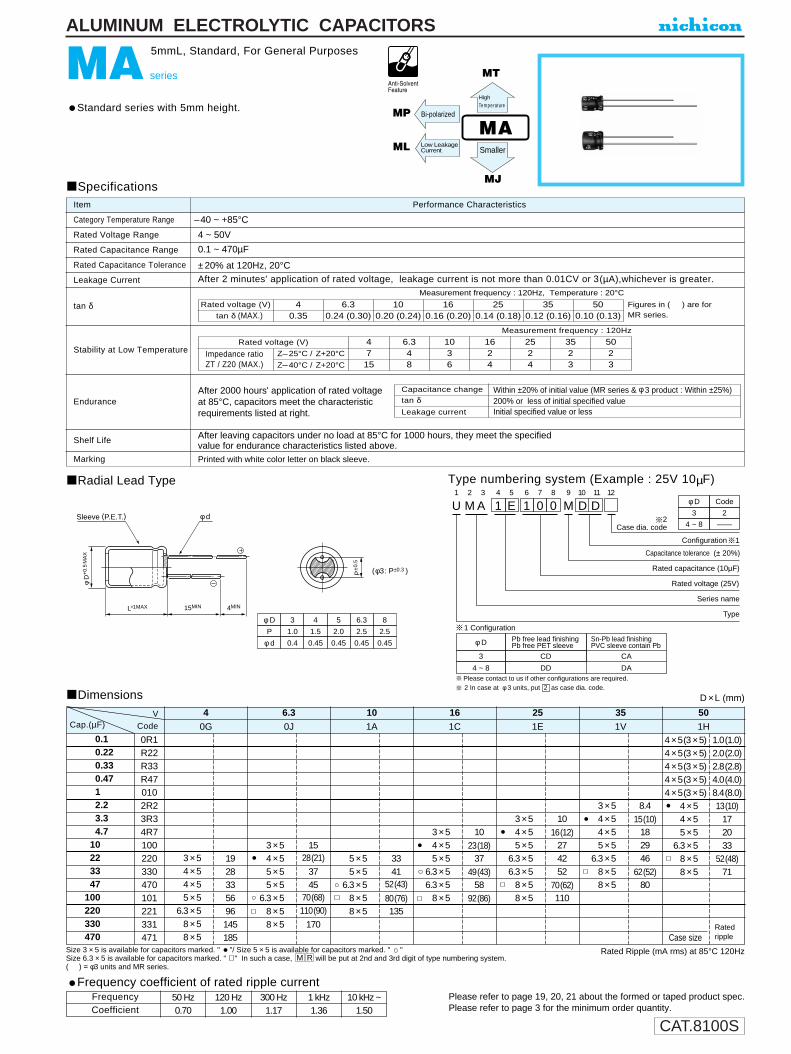
CAT.8100S
U1
M2
A 3
14
E5
16
07
08
M9
D10
D11 12
Configuration
2Case dia. code
Capacitance tolerance (± 20%)
Rated capacitance (10µF)
Rated voltage (25V)
Series name
Type
2 In case at φ 3 units, put 2 as case dia. code.
φ D
3
Pb free lead finishingPb free PET sleeve
Sn-Pb lead finishingPVC sleeve contain Pb
CD CA
4 ~ 8 DD DA
φ D3
Code
2
4 ~ 8 —
( φ 3 : P±0.3 )
φ D
P
φ d
3
1.0
0.4
4
1.5
0.45
5
2.0
0.45
6.3
2.5
0.45
8
2.5
0.45
P±0
.5
L+1MAX 15MIN 4MIN
φ D
+0.
5M
AX
Sleeve (P.E.T.) φ d
1 Configuration
1
Please contact to us if other configurations are required.
ALUMINUM ELECTROLYTIC CAPACITORS
MA series
5mmL, Standard, For General Purposes
Standard series with 5mm height.
Radial Lead Type
Dimensions
Type numbering system (Example : 25V 10µF)
Specifications
Category Temperature Range
Rated Voltage Range
Rated Capacitance Range
Rated Capacitance Tolerance
Leakage Current
tan δ
Stability at Low Temperature
Endurance
Shelf Life
Marking
Performance CharacteristicsItem
–40 ~ +85°C
4 ~ 50V
0.1 ~ 470µF
±20% at 120Hz, 20°CAfter 2 minutes' application of rated voltage, leakage current is not more than 0.01CV or 3(µA),whichever is greater.
Printed with white color letter on black sleeve.
Figures in ( ) are forMR series.
Measurement frequency : 120Hz
After leaving capacitors under no load at 85°C for 1000 hours, they meet the specifiedvalue for endurance characteristics listed above.
Rated voltage (V)
tan δ (MAX.)4
0.356.3
0.24 (0.30)10
0.20 (0.24)16
0.16 (0.20)25
0.14 (0.18)35
0.12 (0.16)50
0.10 (0.13)
D ×L (mm)
MA
MT
Bi-polarized
MJ
MP
ML
Z–25°C / Z+20°C
Z–40°C / Z+20°C
Rated voltage (V)
Impedance ratioZT / Z20 (MAX.)
4715
6.348
1036
1624
2524
3523
5023
Rated Ripple (mA rms) at 85°C 120HzSize 3 × 5 is available for capacitors marked. " "/ Size 5 × 5 is available for capacitors marked. " "Size 6.3 × 5 is available for capacitors marked. " " In such a case, will be put at 2nd and 3rd digit of type numbering system.( ) = φ3 units and MR series.
RM
Measurement frequency : 120Hz, Temperature : 20°C
0.10.220.330.4712.23.34.7
10223347
100220330470
0R1R22R33R470102R23R34R7100220330470101221331471
0.3 × 50.4 × 50.4 × 50.5 × 56.3 × 50.8 × 50.8 × 5
1928335696145185
0G
4
0.3 × 50.4 × 50.5 × 50.5 × 56.3 × 50.8 × 50.8 × 5
1528(21)
3745
70(68)110(90)
170
0J
6.3
0.5 × 50.5 × 56.3 × 50.8 × 50.8 × 5
3341
52(43)
80(76)135
1A
10
0.3 × 50.4 × 50.5 × 56.3 × 56.3 × 50.8 × 5
10
23(18)37
49(43)58
92(86)
1C
16
0.3 × 50.4 × 50.5 × 56.3 × 56.3 × 50.8 × 50.8 × 5
10
16(12)274252
70(62)110
1E
25
0.3 × 50.4 × 50.4 × 50.5 × 56.3 × 50.8 × 50.8 × 5
8.4
15(10)182946
62(52)80
1V
35
4 × 5(3 × 5)4 × 5(3 × 5)4 × 5(3 × 5)4 × 5(3 × 5)4 × 5(3 × 5)
0.4 × 50.4 × 50.5 × 56.3 × 50.8 × 50.8 × 5
1.0(1.0)2.0(2.0)2.8(2.8)4.0(4.0)8.4(8.0)13(10)
172033
52(48)71
1H
50
RatedrippleCase size
Cap.(µF) CodeV
HighTemperature
After 2000 hours' application of rated voltageat 85°C, capacitors meet the characteristicrequirements listed at right.
Capacitance change
Leakage current
tan δWithin ±20% of initial value (MR series & φ 3 product : Within ±25%)200% or less of initial specified valueInitial specified value or less
Low LeakageCurrent Smaller
Please refer to page 19, 20, 21 about the formed or taped product spec.Please refer to page 3 for the minimum order quantity.
Frequency coefficient of rated ripple current
CoefficientFrequency 50 Hz 120 Hz 300 Hz 1 kHz 10 kHz ~
0.70 1.00 1.17 1.36 1.50

CAT.8100S
3523
φD
P
φd
4
1.5
0.45
5
2.0
0.45
6.3
2.5
0.45
P±0
.5
L+1MAX 15MIN 4MIN
φD+
0.5
MA
X
Sleeve φ d
ALUMINUM ELECTROLYTIC CAPACITORS
MC series
5mmL, For Audio Equipment
"nichicon MUSE" acoustic series, with 5mm height.Ideally suited for very compact audio products in very thin and small dimensions.
Radial Lead Type Type numbering system (Example : 25V 10µF)
U1
M2
C3
14
E5
16
07
08
M9
D10
J11
Configuration
Capacitance tolerance (±20%)
Rated Capacitance (10µF)
Rated voltage (25V)
Series name
Type
φD
4 ~ 6.3
Code
DJ
Please contact to us if Eco-Products are required.
Specifications
Category Temperature Range
Rated Voltage Range
Rated Capacitance Range
Capacitance Tolerance
Leakage Current
tan δ
Stability at Low Temperature
Endurance
Shelf Life
Marking
Performance CharacteristicsItem
–40 ~ +85°C
4 ~ 50V
0.1 ~ 220µF
±20% at 120Hz, 20°C
After 2 minutes' application of rated voltage, leakage current is not more than 0.01CV or 3 (µA) ,whichever is greater.
Printed with white color letter on black sleeve.
Measurement frequency : 120Hz
Capacitance change
Leakage current
After 1000 hours' application of rated voltage at85°C, capacitors meet the characteristicsrequirement listed at right.
After leaving capacitors under no load at 85°C tor 1000 hours, they meet the specifiedvalue for endurance characteristics listed above.
tan δWithin ±20% of initial value200% or less of initial specified valueInitial specified value or less
Rated voltage (V)tan δ (MAX.)
40.35
6.30.24
100.20
160.16
250.14
Z–25°C / Z+20°C
Z–40°C / Z+20°C
Rated voltage (V)
Impedance ratioZT / Z20 (MAX.)
4715
6.348
1036
1624
2524
MC
350.12
500.10
Measurement frequency : 120Hz, Temperature : 20°C
5023
SK
0.10.220.330.4712.23.34.7
10223347
100220
0R1R22R33R470102R23R34R7100220330470101221
4 × 54 × 55 × 5
6.3 × 5
28335696
0GCap.(µF)
V
Rated Ripple (mA rms) at 85°C 120Hz
4
4 × 55 × 55 × 5
6.3 × 5
28374570
0J
6.3
5 × 55 × 5
6.3 × 5
334152
1A
10
4 × 55 × 5
6.3 × 56.3 × 5
23374958
1C
16
4 × 55 × 5
6.3 × 56.3 × 5
16274252
1E
25
4 × 55 × 5
6.3 × 5
182946
1V
35
4 × 54 × 54 × 54 × 54 × 54 × 54 × 55 × 5
6.3 × 5
Case size
1.02.02.84.08.4
13172033
1H
50Code
D × L (mm) Dimensions
Smaller
Please refer to page 19, 20, 21 about the formed or taped product spec.Please refer to page 3 for the minimum order quantity.
Frequency coefficient of rated ripple current
CoefficientFrequency 50 Hz 120 Hz 300 Hz 1 kHz 10 kHz ~
0.70 1.00 1.17 1.36 1.50
Ratedripple

CAT.8100S
11.52.23.34.76.8
101522334768
100
0101R52R23R34R76R8100150220330470680101
4 × 55 × 55 × 5
6.3 × 56.3 × 5
0J
6.31A
101C
161E
251V
35
5.02.62.61.31.3
508080
115115
5 × 55 × 5
6.3 × 5
2.62.61.3
8080
115
4 × 55 × 55 × 5
6.3 × 56.3 × 5
5.02.62.61.31.3
508080
115115
4 × 54 × 55 × 5
6.3 × 56.3 × 56.3 × 5
5.05.02.61.31.31.3
505080
115115115
4 × 54 × 54 × 54 × 54 × 55 × 55 × 5
6.3 × 56.3 × 5
5.05.05.05.05.02.62.61.31.3
50505050508080
115115
P±0
.5
L+1MAX 15 MIN 4 MIN
φ D
+0.
5M
AX
φ d
φ DP
φ d
4
1.5
0.45
6.3
2.5
0.45
5
2.0
0.45
Sleeve (P.E.T.)
ALUMINUM ELECTROLYTIC CAPACITORS
MF series
5mmL, Low Impedance
Low impedance over wide temperature range of –55 ~ +105°C, with 5mm height.Suited for DC-DC converters where smaller case size and lower impedance are required.
Radial Lead Type
Dimensions
Type numbering system (Example : 25V 10µF)
U1
M2
F3
14
E5
16
07
08
M9
D10
D11
Configuration
Capacitance tolerance (± 20%)
Rated capacitance (10µF)
Rated voltage (25V)
Series name
Type
φ D
4 ~ 6.3
Pb free lead finishingPb free PET sleeve
Sn-Pb lead finishingPVC sleeve contain Pb
DD DH
Configuration
Please contact to us if other configurations are required.
Specifications
Category Temperature Range
Rated Voltage Range
Rated Capacitance Range
Rated Capacitance Tolerance
Leakage Current
tan δ
Stability at Low Temperature
Endurance
Shelf Life
Marking
Performance CharacteristicsItem
–55 ~ +105°C
6.3 ~ 35V
1 ~ 100µF
±20% at 120Hz, 20°C
After 2 minutes' application of rated voltage, leakage current is not more than 0.01CV or 3 (µA), whichever is greater.
Printed with white color letter on dark brown sleeve.
After 1000 hours' application of rated voltageat 105°C capacitors meet the characteristicrequirements listed at right.
After leaving capacitors under no load at 105°C for 1000 hours, they meet the specified value for endurance characteristics listed above.
MF MT
Rated voltage (V)
tan δ (MAX.)
Z–25°C / Z+20°C
Z–55°C /Z+20°C
Rated voltage (V)
Impedance ratioZT / Z20 (MAX.)
6.324
1024
1623
2523
3523
6.30.22
100.20
160.18
250.14
350.12
D ×L (mm)
Max. Impedance (Ω) at 20°C 100kHzRated Ripple (mA rms) at 105°C 100kHz
Case size Impedance Ratedripple
Cap.(µF) CodeV
LowImpedance
Measurement frequency : 120Hz
Measurement frequency : 120Hz, Temperature : 20°C
Leakage current
tan δCapacitance change Within ±20% of initial value
200% or less of initial specified valueInitial specified value or less
Please refer to page 19, 20, 21 about the formed or taped product spec.Please refer to page 3 for the minimum order quantity.
Frequency coefficient of rated ripple current
CoefficientFrequency 50 Hz 120 Hz 300 Hz 1 kHz 10 kHz ~
0.35 0.50 0.64 0.83 1.00

CAT.8100S
ALUMINUM ELECTROLYTIC CAPACITORS
※Trimmed (Cut) or Formed Leads
Radial lead typeIn order to identify correct part number for the processed lead product, cut/formed lead code must be added to bulk part number.If the bulk part number is up to 11th digit,Iprocessed lead coding shall be as follows:
In case 12th digit is alphabet, it shall be:
In case 12th digit is numeral, it shall be:
∗ Lead diameter (φd) and lead pitch (P) are subject to capacitor specifications.
12 13
code
14
12 13 141
code
14 15
code
1612 13
Cut / Formed lead code Dimensions (mm)Configurations Code Applicable series φD F L r
Lead configurations
4 5 5.0 —5mmL,7mmL series
5 5 5.0 —
Other series6.3 5 5.0 —
8 5 5.0 —Forming and cutting
4 5 3.5 —5mmL,7mmL series
5 5 3.5 —
Other series6.3 5 3.5 —
8 5 3.5 —
3 1.0 5.0 —
4 1.5 5.0 —
5 2.0 5.0 —
6.3 2.5 5.0 —
8 ※3.5 5.0 —
10 5 5.0 —Cutting All series
12.5 5 5.0 —
16 7.5 5.0 —
18 7.5 5.0 —
20 10 5.0 —
22 10 5.0 —
25 12.5 5.0 —
All series Same as above. 4.5 —
All series Same as above. 4.0 —
All series Same as above. 3.5 —
All series Same as above. 3.2 —
All series Same as above. 3.0 —
4 5 4.5 1.15mmL,7mmL series
5 5 4.5 1.1
Other series6.3 5 4.5 1.1
8 5 4.5 1.3
10 5 4.5 1.3Snap-in
12.5 5 4.5 1.3
16 7.5 4.5 1.3All series
18 7.5 4.5 1.3
20 10 5.0 1.8
22 10 5.0 1.8
25 12.5 5.0 1.8
(Code , ) 1.5MAXB A B B(Code , ) 2.5MAXF A F V
L±0.5
φD F±0
.5
P±0.5
φd
(mm)
L±0.5
φD F±0
.5
φd
(Code ) 1.5MAXA E(Code ) 2.5MAX
(φ4, 5, 6.3, 8)
(φ10, 12.5, 16,
18, 20, 22, 25)A A
L±0.5
φD F±0
.5P±0.5
φd
L±0.5
φD F±0
.5
φdrr
B A
B B
F V
C A
C P
C C
C V
C T
C M
A A
A E
A A
F A
※φ8 × 5 = F: 2.5

CAT.8100S
Radial lead type (Applicable standard JIS C0806-2)In order to identify correct part number forthe taped product, taping code must beadded.
If the bulk part number is up to 11th digit,taping code shall be as follows:
In case 12th digit is numeral, it shall be
※Taped Leads for Automatic Insertion Systems※Solid conductive polymer capacitors are only available for straight lead.
Notes:※1 F = 2.0mm is also available, provided
that capacitor body height is less than 9mm.Taping code to be .
※2 Tolerance on F for φ16 and φ18 unitsshall be ±0.8mm.
※3 Tolerance on Ho for φ3 units shall be 16.0MIN.
Special taping specifications on H. F. and K. dimensions other than the above figures areavailable upon request.
12 13 141
code
12 13
code
14
Specifications Capacitor Taping codediameter
Packaging Lead style Leader F P0 (φ) Code Applicable size
Formed lead See Table 1 12.7 3 ~ 8
See Table 2 12.7 4 ~ 10 T P Body length (5mmL, 7mmL)Ammo-pack
Straight leadT D (φ8×7, φ5×9 ~ φ10×25)
See Table 2 15.0 12.5 T O (φ12.5×12.5 ~ φ12.5×25)
See Table 2 15.0 16, 18 T N (φ16, φ18×15 ~ 25)
T E Body length (5mmL, 7mmL)T P (φ3 × 5)T A (φ5×9 ~ φ8×9, φ5×11 ~ φ8×20)
–+
Case SizeStraight Lead Type
Toleranceφ16
Itemφ4 φ5 φ6.3 φ8 × 5 φ8 × 7 φ8 φ10 φ12.5 φ18
TP TP, TD TP, TD TP TD TD TD TO TN
φd Lead-wire diameter ±0.05 0.45 0.45 0.5 0.6 0.6 0.6 0.8
P Pitch of component ±1.0 12.7 12.7 12.7 12.7 12.7 12.7 12.7 15.0 30.0
P0 Feed hole pitch ±0.2 12.7 12.7 12.7 12.7 12.7 12.7 12.7 15.0 15.0
P1 Hole center to lead ±0.5 5.1 5.1 4.6 4.6 3.85 5.0 3.75
P2 ±1.0 6.35 6.35 6.35 6.35 6.35 6.35 6.35 7.5 7.5
F 2.5※1 2.5※1 2.5 2.5 3.5 3.5 5.0 5.0 7.5※2
H 18.5 18.5 18.5 18.5 18.5 18.5 18.5 18.5 18.5
W Tape Width ±0.5 18.0 18.0 18.0 18.0 18.0 18.0 18.0 18.0 18.0
W0 MIN 7.0 7.0 7.0 7.0 7.0 7.0 7.0 12.5 12.5
φD0 Feed hole diameter ±0.2 4.0 4.0 4.0 4.0 4.0 4.0 4.0 4.0 4.0
t Total tape thickness ±0.2 0.6 0.6 0.6 0.6 0.6 0.6 0.6 0.6 0.6
+0.8–0.2
+0.75–0.5
0.450.5
0.450.5
Feed hole centerto component center
Lead-to-leaddistance
Height of componentfrom tape center
Hold down tapewidth
5.1(※1 5.35)
5.1(※1 5.35)
Formed Lead Type
Toleranceφ8 × 9
φ4 × 11 φ6.3 × 9 φ8 × 11.5φ3 × 5 φ4 × 5 φ5 × 5 φ5 × 9 φ6.3 × 5 φ8 × 5 φ6.3 × 11 φ8 × 15Item φ4 × 7 φ5 × 7 φ5 × 11 φ6.3 × 7 φ8 × 7 φ6.3 × 15 φ8 × 20
TP TE TE TA TE TE TA TA
φd Lead-wire diameter ±0.05 0.40 0.45 0.45 0.45 0.5 0.6
P Pitch of component ±1.0 12.7 12.7 12.7 12.7 12.7 12.7 12.7 12.7
P0 Feed hole pitch ±0.2 12.7 12.7 12.7 12.7 12.7 12.7 12.7 12.7
P1 Hole center to lead ±0.5 5.1 3.85 3.85 3.85 3.85 3.85 3.85 3.85
P2 ±1.0 6.35 6.35 6.35 6.35 6.35 6.35 6.35 6.35
F 2.5 5.0 5.0 5.0 5.0 5.0 5.0 5.0
K Clinch height MAX 1.5 1.5 1.5 2.5 1.5 1.5 2.5 4.0
H 18.5 17.5 17.5 18.5 17.5 17.5 18.5 20.0
H0 ±0.5 16.0 ※3 16.0 16.0 16.0 16.0 16.0 16.0 16.0
W Tape Width ±0.5 18.0 18.0 18.0 18.0 18.0 18.0 18.0 18.0
W0 MIN 7.0 7.0 7.0 7.0 7.0 7.0 7.0 7.0
φD0 Feed hole diameter ±0.2 4.0 4.0 4.0 4.0 4.0 4.0 4.0 4.0
t Total tape thickness ±0.2 0.6 0.6 0.6 0.6 0.6 0.6 0.6 0.6
Feed hole centerto component centerLead-to-leaddistance
Height of componentfrom tape centerLead-wire clinch
height
Hold down tapewidth
+0.8–0.2
+0.75–0.5
0.450.5
0.450.5
(Formed lead type)
(Straight lead type)
H
PP2
P1
P0
F
φd D0
ww0
H0
K
H
PP2
P1
P0 φd D0
ww0
F
t
t
Table 1
Table 2
(mm)
(mm)
(mm)
Case Size
Taping Code
Taping Code
T C
ALUMINUM ELECTROLYTIC CAPACITORS
F
φ4, 5

CAT.8100S
ALUMINUM ELECTROLYTIC CAPACITORS
L H W Q'ty / BoxCase Size3 × 54 × 5, 4 × 75 × 5, 5 × 78 × 5, 8 × 76.3 × 5, 6.3 × 6, 6.3 × 74 × 11, 5 × 9, 5 × 118 × 9, 8 × 10, 8 × 11.5, 8 × 1510 × 8, 10 × 9, 10 × 10, 10 × 12.5, 10 × 15, 10 × 166.3 × 9, 6.3 × 11, 6.3 × 158 × 2010 × 20
12.5 × 12.5, 12.5 × 15, 12.5 × 2012.5 × 2518 × 15, 18 × 20, 18 × 2516 × 15, 16 × 20, 16 × 25
340340
340
340340
340340
330
320
340
340
150200
300
300200
260200
290
230
260
250
5050
50
5454
6262
65
65
54
50
(mm)
2000200020001000200020001000500
2000
10 × 25340 200 65 500
1000500
250250
500
Axial lead type (Applicable standard JIS C0805)The following code shall be put at 12th ~ 14th digit of the corresponding type number of capacitors.
PackagingAmmo-pack (Flat box type)
Taping SpecificationsDim. W
(Tape distance)Dim. P
(Component Pitch)
52.4 10
63.5 10
73.0 10
52.4 15
63.5 15
73.0 15
Case dia (φ) Taping code
1LS
1LV
1LY
1LT
1LW
1LZ
Q'ty / Reel (pcs.)
5
6.3856.3856.381013 (except 31.5L)
10131013
160013001000160013001000160013001000500
350500350
500
350
Please contact us for complete information on the package
dimensions for tapes axial lead capacitors.
+
-
+
-
L
H
W
w±1
.5
w±1
.22
6±1
P±0.51.2MAX
2M
AX
—
White tape forpositive polarity
+
Blue or yellow tape fornegative polarity
D
(mm)
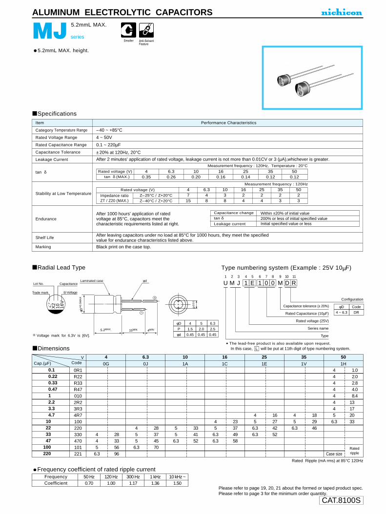
CAT.8100S
φD
P
φd
4
1.5
0.45
5
2.0
0.45
6.3
2.5
0.45
Voltage
CapacitanceLot No.
Trade mark
X2
10 16V
φd Laminated case
5.2MAX. 15MIN 4MIN
φD+
0.5
MA
X
P±0
.5
ALUMINUM ELECTROLYTIC CAPACITORS
MJ series
5.2mmL MAX.
5.2mmL MAX. height.
Radial Lead Type Type numbering system (Example : 25V 10µF)
U1
M2
J3
14
E5
16
07
08
M9
D10
R11
Configuration
Capacitance tolerance (± 20%)
Rated Capacitance (10µF)
Rated voltage (25V)
Series name
Type
φD
4 ~ 6.3
Code
DR
Specifications
Category Temperature Range
Rated Voltage Range
Rated Capacitance Range
Capacitance Tolerance
Leakage Current
tan δ
Stability at Low Temperature
Endurance
Shelf Life
Marking
Performance CharacteristicsItem
–40 ~ +85°C
4 ~ 50V
0.1 ~ 220µF
±20% at 120Hz, 20°C
After 2 minutes' application of rated voltage, leakage current is not more than 0.01CV or 3 (µA),whichever is greater.
Black print on the case top.
Measurement frequency : 120Hz, Temperature : 20°C
Measurement frequency : 120Hz
After 1000 hours' application of ratedvoltage at 85°C, capacitors meet thecharacteristic requirements listed at right.
After leaving capacitors under no load at 85°C for 1000 hours, they meet the specified value for endurance characteristics listed above.
Rated voltage (V)tan δ (MAX.)
Z–25°C / Z+20°C
Z–40°C / Z+20°C
Rated voltage (V)
Impedance ratioZT / Z20 (MAX.)
6.30.26
40.35
100.20
160.16
250.14
350.12
500.12
4715
6.348
1038
1624
2524
3523
5023
Dimensions
Rated Ripple (mA rms) at 85°C 120Hz
Voltage mark for 6.3V is [6V].
0.10.220.330.4712.23.34.7
10223347
100220
0R1R22R33R470102R23R34R7100220330470101221
445
6.3
28335696
0G
40J
6.31A
101C
161E
251V
351H
50
455
6.3
28374570
55
6.3
334152
45
6.36.3
23374958
45
6.36.3
16274252
45
6.3
182946
44444445
6.3
1.02.02.84.08.4
13172033
Case sizeRatedripple
VCap.(µF) Code
Capacitance change
Leakage current
tan δWithin ±20% of initial value200% or less of initial specified valueInitial specified value or less
Please refer to page 19, 20, 21 about the formed or taped product spec.Please refer to page 3 for the minimum order quantity.
Frequency coefficient of rated ripple current
CoefficientFrequency 50 Hz 120 Hz 300 Hz 1 kHz 10 kHz ~
0.70 1.00 1.17 1.36 1.50
• The lead-free product is also available upon request.In this case, will be put at 11th digit of type numbering system.L

CAT.8100S
φ DP
φ d
4
1.5
5
2.00.450.45
6.3
2.50.45
P±0
.5
L+1MAX 15MIN 4MIN
φ D
+0.
5M
AX
φ d Sleeve (P.E.T.) U1
M2
L3
14
A5
36
37
08
M9
D10
D11
Configuration
Capacitance tolerance (± 20%)
Rated capacitance (33µF)
Rated voltage (10V)
Serise name
Type
φ D
4 ~ 6.3
Pb free lead finishingPb free PET sleeve
Sn-Pb lead finishingPVC sleeve contain Pb
DD DA
Configuration
Please contact to us if other configurations are required.
ALUMINUM ELECTROLYTIC CAPACITORS
ML series
5mmL, Low Leakage Current
Low leakage current series with 5mm height.
Radial Lead Type Type numbering system (Example : 10V 33µF)
Specifications
Category Temperature Range
Rated Voltage Range
Rated Capacitance Range
Rated Capacitance Tolerance
Leakage Current
tan δ
Stability at Low Temperature
Endurance
Shelf Life
Marking
Performance CharacteristicsItem
–40 ~ +85°C
4 ~ 50V
0.1 ~ 100µF
±20% at 120Hz, 20°C
After 2 minutes' application of rated voltage, leakage current is not more than 0.002CV or 0.4 (µA),whichever is greater.
Printed with white color letter on black sleeve. (PVC sleeve product : Printed with black color letter on yellow sleeve.)
Measurement frequency : 120Hz
After 1000 hours' application of rated voltageat 85°C, capacitors meet the characteristicrequirements listed at right.
After leaving capacitors under no load at 85°C for 1000 hours, they meet the specifiedvalue for endurance characteristics listed above.
Z–25°C / Z+20°C
Z–40°C / Z+20°C
Rated voltage (V)
Impedance ratioZT / Z20 (MAX.)
4715
6.3410
1038
1626
2524
3523
5023
Rated Ripple (mA rms) at 85°C 120Hz
Measurement frequency : 120Hz, Temperature : 20°C
Rated voltage (V)
tan δ (MAX.)4
0.356.30.24
100.20
160.16
250.14
350.12
500.10
Dimensions D ×L (mm)
0.10.220.330.4712.23.34.7
10223347
100
0R1R22R33R470102R23R34R7100220330470101
0.5 × 50.5 × 56.3 × 5
283356
0G
40J
6.31A
101C
161E
251V
351H
50
0.4 × 50.5 × 50.5 × 56.3 × 5
28374570
0.5 × 50.5 × 56.3 × 5
334152
0.4 × 50.5 × 56.3 × 56.3 × 5
23374958
0.4 × 50.5 × 56.3 × 56.3 × 5
16274252
0.4 × 50.5 × 56.3 × 5
182946
0.4 × 50.4 × 50.4 × 50.4 × 50.4 × 50.4 × 50.5 × 50.5 × 56.3 × 5
Case size
1.02.02.84.08.4
13172033
VCodeCap.(µF)
Ratedripple
Capacitance change
Leakage current
tan δWithin ±20% of initial value200% or less of initial specified valueInitial specified value or less
Please refer to page 19, 20, 21 about the formed or taped product spec.Please refer to page 3 for the minimum order quantity.
Frequency coefficient of rated ripple current
CoefficientFrequency 50 Hz 120 Hz 300 Hz 1 kHz 10 kHz ~
0.70 1.00 1.17 1.36 1.50
ML MALow LeakageCurrent

CAT.8100S
φ DP
φ d
4
1.5
5
2.00.450.45
6.3
2.50.45
P±0
.5
L+1MAX 15 MIN 4 MIN
φ D
+0.
5M
AX
φ d Sleeve (P.E.T.)
ALUMINUM ELECTROLYTIC CAPACITORS
MP series
5mmL, Bi-Polarized
Bi-polarized series with 5mm height.
Radial Lead Type
Dimensions
Type numbering system (Example : 10V 33µF)
U1
M2
P3
14
A5
36
37
08
M9
D10
D11
Configuration
Capacitance tolerance (± 20%)
Rated capacitance (33µF)
Series name
Type
Rated voltage (10V)
φ D
4 ~ 6.3
Pb free lead finishingPb free PET sleeve
Sn-Pb lead finishingPVC sleeve contain Pb
DD DA
Configuration
Please contact to us if other configurations are required.
Specifications
Category Temperature Range
Rated Voltage Range
Rated Capacitance Range
Rated Capacitance Tolerance
Leakage Current
tan δ
Stability at Low Temperature
Endurance
Shelf Life
Marking
Performance CharacteristicsItem
–40 ~ +85°C
6.3 ~ 50V
0.1 ~ 47µF
±20% at 120Hz, 20°C
After 2 minutes' application of rated voltage, leakage current is not more than 0.05CV or 10 (µA), whichever is greater.
Printed with white color letter on black sleeve.
Measurement frequency : 120Hz, Temperature : 20°C
Measurement frequency : 120Hz
After 2000 hours' application of rated voltageat 85°C with the polarity inverted every 250hours, capacitors meet the characteristicrequirements listed at right.
After leaving capacitors under no load at 85°C for 1000 hours, they meet the specified value for endurance characteristics listed above.
MP Bi-polarized MA
Rated voltage (V)
tan δ (MAX.)6.30.24
100.20
160.17
250.17
350.15
500.15
Z–25°C / Z+20°C
Z–40°C / Z+20°C
Rated voltage (V)
Impedance ratioZT / Z20 (MAX.)
6.348
1036
1624
2524
3523
5023
D ×L (mm)
Rated Ripple (mA rms) at 85°C 120Hz
0.100.220.330.4710.12.203.304.70
100.1220.1330.1470.1
0R1R22R33R470102R23R34R7100220330470
0.5 × 56.3 × 56.3 × 5
283745
0J
V 6.3
0.4 × 56.3 × 56.3 × 5
173341
1A
10
0.4 × 50.5 × 56.3 × 56.3 × 5
12233749
1C
16
0.5 × 50.5 × 56.3 × 5
121627
1E
25
0.4 × 50.5 × 50.5 × 56.3 × 5
8.4161829
1V
35
0.4 × 50.4 × 50.4 × 50.4 × 50.4 × 50.5 × 50.5 × 56.3 × 5
Case size
1.02.02.84.08.4
131720
Rated
ripple
1H
50Cap.(µF) Code
Capacitance change
Leakage current
tan δWithin ±20% of initial value200% or less of initial specified valueInitial specified value or less
Please refer to page 19, 20, 21 about the formed or taped product spec.Please refer to page 3 for the minimum order quantity.
Frequency coefficient of rated ripple current
CoefficientFrequency 50 Hz 120 Hz 300 Hz 1 kHz 10 kHz ~
0.70 1.00 1.17 1.36 1.50

CAT.8100S
φ DP
φ d
31.00.40
6.32.5
0.45
41.50.45
52.0
0.45
(φ 3 : P±0.3)P±0
.5
L+1MAX 15 MIN 4 MIN
φ D
+0.
5M
AX
φ d Sleeve (P.E.T.)
2 For φ 3mm unit, place case dia. code of 2 to 12th digit.
U1
M2
T3
14
E5
16
07
08
M9
D10
D11 12
Configuration 1
Capacitance tolerance (± 20%)
2Case dia code
Rated capacitance (10µF)
Rated voltage (25V)
Series name
Type
φ D3
Code
2
4 ~ 6.3 —
φ D
3
Pb free lead finishingPb free PET sleeve
Sn-Pb lead finishingPVC sleeve contain Pb
CD CH
4 ~ 6.3 DD DH
1 Configuration
1 Please contact to us if other configurations are required.
ALUMINUM ELECTROLYTIC CAPACITORS
MT series
5mmL, Wide Temperature Range
Wide temperature range of –55 ~ +105°C, with 5mm height.
Radial Lead Type
Dimensions
Type numbering system (Example : 25V 10µF)
Specifications
Category Temperature Range
Voltage Range
Rated Capacitance Range
Rated Capacitance Tolerance
Leakage Current
tan δ
Stability at Low Temperature
Endurance
Shelf Life
Marking
Performance CharacteristicsItem
–55 ~ +105°C
4 ~ 50V
0.1 ~ 100µF
±20% at 120Hz, 20°C
After 2 minutes' application of rated voltage, leakage current is not more than 0.01CV or 3 (µA), whichever is greater.
Printed with white color letter on black sleeve.
Measurement frequency : 120Hz
After 1000 hours' application of rated voltageat 105°C, capacitors meet the characteristicrequirements listed at right.
After leaving capacitors under no load at 105°C for 1000 hours, they meet the specified value for endurance characteristics listed above.
Z–25°C / Z+20°C
Z–40°C / Z+20°C
Rated voltage (V)
Impedance ratioZT / Z20 (MAX.)
4612
6.338
1035
1624
2523
3523
5023
D ×L (mm)
Rated Ripple (mA rms) at 105°C 120HzSize 3 × 5 is available for capacitors marked " "Figures in ( ) are for φ 3 product.
MT
MA
0.10.220.330.4712.23.34.7
10223347
100
0R1R22R33R470102R23R34R7100220330470101
4 × 55 × 55 × 5
6.3 × 5
22303660
0G
40J
6.31A
101C
161E
251V
351H
50
4 × 55 × 55 × 5
6.3 × 5
5 × 55 × 5
6.3 × 5
4 × 55 × 5
6.3 × 56.3 × 5
4 × 55 × 5
6.3 × 56.3 × 5
3 × 54 × 54 × 55 × 5
6.3 × 5
4 × 54 × 54 × 54 × 54 × 54 × 54 × 55 × 5
6.3 × 522303660
273546
18 (14)304050
13 (10)233848
7.511 (9)152548
1.02.63.23.8
6.2 (5.9)11 (9)141930
Case size
Cap.(µF) CodeV
Measurement frequency : 120Hz, Temperature : 20°C
Rated voltage (V)
tan δ (MAX.)4
0.376.30.28
100.24
160.20
250.16
350.13 (0.14)
500.12 (0.14)
Figures in ( ) are for φ 3 product.
HighTemperature
Leakage current
tan δ
Capacitance change
Initial specified value or less
200% or less of initial specified value
Within ±25% of initial value (φ 3mm unit,and <= 16V)Within ±20% of initial value ( >= 25V)
Ratedripple
Please refer to page 19, 20, 21 about the formed or taped product spec.Please refer to page 3 for the minimum order quantity.
Frequency coefficient of rated ripple current
CoefficientFrequency 50 Hz 120 Hz 300 Hz 1 kHz 10 kHz ~
0.70 1.00 1.17 1.36 1.50
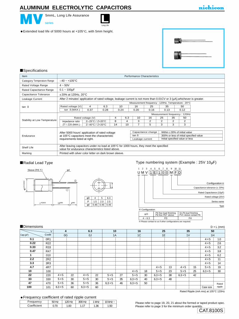
CAT.8100S
Please refer to page 19, 20, 21 about the formed or taped product spec.Please refer to page 3 for the minimum order quantity.
φD
Pφd
4
1.50.45
5
2.00.45
6.3
2.50.45
L+1MAX 15MIN 4MIN
φd
φD+
0.5
MA
X
P±0
.5
Sleeve (P.E.T.)
ALUMINUM ELECTROLYTIC CAPACITORS
MV series
5mmL, Long Life Assurance
Extended load life of 5000 hours at +105°C, with 5mm height.
Radial Lead Type
Dimensions
Type numbering system (Example : 25V 10µF)
Specifications
Category Temperature Range
Rated Voltage Range
Rated Capacitance Range
Capacitance Tolerance
Leakage Current
tan δ
Stability at Low Temperature
Endurance
Shelf Life
Marking
Performance CharacteristicsItem
–40 ~ +105°C
4 ~ 50V
0.1 ~ 100µF
±20% at 120Hz, 20°C
After 2 minutes' application of rated voltage, leakage current is not more than 0.01CV or 3 (µA),whichever is greater.
Printed with silver color letter on dark brown sleeve.
Measurement frequency : 120Hz, Temperature : 20°C
Measurement frequency : 120Hz
After 5000 hours' application of rated voltageat 105°C capacitors meet the characteristicrequirements listed at right.
After leaving capacitors under no load at 105°C for 1000 hours, they meet the specified value for endurance characteristics listed above.
D × L (mm)
Rated voltage (V)tan δ (MAX.)
40.37
6.30.28
100.24
160.20
250.16
350.13
500.12
Z–25°C / Z+20°C
Z–40°C / Z+20°C
Rated voltage (V)
Impedance ratioZT / Z20 (MAX.)
4814
6.3410
1037
1625
2523
3523
5023
Rated Ripple (mA rms) at 105°C 120Hz
U1
M2
V3
14
E5
16
07
08
M9
F10
D11
Configuration
Capacitance tolerance (± 20%)
Rated Capacitance (10µF)
Rated voltage (25V)
Series name
Type
φ D
4 ~ 6.3
Pb free lead finishingPb free PET sleeve
Sn-Pb lead finishingPVC sleeve contain Pb
FD FH
Configuration
Please contact to us if other configurations are required.
0.10.220.330.4712.23.34.7
10223347
100
0R1R22R33R470102R23R34R7100220330470101
4 × 55 × 55 × 5
6.3 × 5
22303660
0G
40J
6.31A
101C
161E
251V
351H
50
4 × 55 × 55 × 5
6.3 × 5
22303660
5 × 55 × 5
6.3 × 5
273546
4 × 55 × 5
6.3 × 56.3 × 5
18304050
4 × 55 × 5
6.3 × 56.3 × 5
13233848
4 × 55 × 5
6.3 × 5
152542
4 × 54 × 54 × 54 × 54 × 54 × 54 × 55 × 5
6.3 × 5
Case size
1.02.63.23.86.211141930
Cap.(µF) CodeV
Capacitance change
Leakage current
tan δWithin ±30% of initial value300% or less of initial specified valueInitial specified value or less
Ratedripple
Frequency coefficient of rated ripple current
CoefficientFrequency 50 Hz 120 Hz 300 Hz 1 kHz 10 kHz ~
0.70 1.00 1.17 1.36 1.50

CAT.8100S
ALUMINUM ELECTROLYTIC CAPACITORS
NR series
Screw Terminal Type
Load life of 5000 hours application of ripple current at 85°C .Extended rarge up to φ100 × 250Rsize.
Specifications
Category Temperature Range
Rated Voltage Range
Rated Capacitance Range
Capacitance Tolerance
Leakage Current
tan δ
Stability at Low Temperature
Endurance
Shelf Life
Marking
Performance CharacteristicsItem
– 40 ~ +85°C (10~100V) , – 25 ~ +85°C (160~250V)
10 ~ 250V
1000 ~ 2200000µF
±20% at 120Hz, 20°C
After 5 minutes' application of rated voltage, leakage current is not more than (µA) or 5 mA, whichever is smaller (at 20°C) .
[C:Rated Capacitance (µF) , V:Voltage(V)]
Printed with black color letter on light blue sleeve.
Measurement frequeny : 120Hz
Rated voltage(V)
After an application of DC voltage (in the range of ratedDC voltage even after over-lapping the specified ripplecurrent) for 5000 hours at 85°C, capacitors meetthe characteristic requirements listed at right.
After leaving capacitors under no load at 85°C
for 1000 hours, they meet the requirements listed at right.
Impedance ratio ZT/Z20(MAX.)
160~25010~100
Z—40°C / Z+20°C
12
Z—25°C / Z+20°C
8
160.40.550.60.8—
0.75—1.11.51.5
250.350.40.450.5—
0.65—
0.751.01.0
350.30.3
0.350.40.5—
0.650.750.90.9
500.250.250.250.30.35——
0.550.750.75
630.250.250.250.250.30.3—0.50.60.6
800.20.20.20.2
0.250.3—
0.350.40.4
1000.120.150.150.15—0.2—0.30.30.3
160~2500.150.150.150.150.20.20.20.20.250.25
NR
NT
NX
Measurement frequency:
120Hz,
Temperature : 20°C35
51
63.5
76.2
90
100
80~100
120
70~100120~140
100120~140
100120~140140~220
250
100.60.70.91.00.91.21.61.62.02.4
φD VL
High ripple,Longer life
Capacitance change
Leakage current
tan δWithin ±15% of initial value
Initial specified value or less
175% or less of initial specified value
Capacitance change
Leakage current
tan δWithin ±20% of initial value
Initial specified value or less
175% or less of initial specified value
HighTem perature
L1
N2
R3
24
E5
26
27
28
M9
S10
M11
Configuration
Capacitance tolerance (±20%)
Rated Capacitance (2200µF)
Rated voltage (250V)
Series name
Type
L1
N2 3
24 5 6 7
28
M9
S10
M11
(φ 35)
(φ 51~ φ 100)
Code lessB
3-leg brackets2-leg brackets
N No brackets
Code less 2-leg bracketsN No brackets
12
Mounting bracket
Type numbering system (Example : 250V 2200µF) Drawingφ 35 Screw terminal type
Pressure relief vent
29±1
45±110
3.5
24
7 +
30°
Sleeve Bottom plate
6±1
12.7
±1
35 +
2MA
X
Hexagenal headed bolt (M5)
L+3MAX.
15±0.5
10
3 CV
Dimension table in next page.
Please contact to us if PVCless products are required.
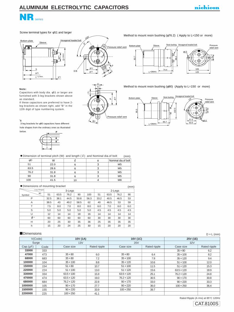
CAT.8100S
NR series
ALUMINUM ELECTROLYTIC CAPACITORS
Dimensions D × L (mm)
Rated Ripple (A rms) at 85°C 120Hz
Dimensions of mounting bracket (mm)
P
7
5
Screw terminal types for φ51 and larger
Pressure relief vent
Pressure relief vent
A±2
120°
30°
SleeveBottom plate
W± 1
D +
2MA
X
Hexagenal headed bolt
P±2
BT
U
S
L+ MAX.
H±1
±1
h
US
P A± 2
TNote:Capacitors with body dia. φ51 or larger arefurnished with 3-leg brackets shown aboveas standard.If these capacitors are preferred to have 2-leg brackets as shown right, add "B" in the12th digit of type numbering system.
P
A
T
S
U
°
H
h
51
32.5
38.5
7.5
5.0
12
60
20
15
63.5
38.1
43
8.0
5.0
14
60
25
20
76.2
44.5
49.2
7.0
5.0
14
60
30
24
90
50.8
58.5
8.0
5.0
18
60
35
25
100
56.3
62
8.0
5.0
16
60
36
30
51
33.2
40
6.0
4.5
14
30
25
15
63.5
40.5
46.5
7.0
4.5
14
30
35
20
76.2
46.5
53
6.0
4.5
14
30
35
20
90
53
59
6.0
4.5
14
30
35
20
3-Legs 2-LegsφD
Symbol
Leg Shape
L+3MAX.
L+3MAX.
74.4
88.2
65.7
Sleeve Resin bushing Hexagenal headed bolt
120
105
Bottom plate
Sleeve Resin bushing Hexagenal headed boltBottom plate
83.7
95.5
φ4.5
Pressurerelief vent
31.8
±1
120°
63.5
57.5
Pressurerelief vent
31.8
±1
φ6.0
102.
5
3-leg brackets for φ90 capacitors have different
hole shapes from the ordinary ones as illustrated
below. P
5
7
P
∗B
330004700068000
100000150000220000330000470000680000
100000015000002200000
333473683104154224334474684105155225
Cap.(µF) Code Case size Rated ripple Case size Rated ripple Case size Rated rippleSurge
V(Code)
35 × 8035 × 8035 × 10051 × 8051 × 100
63.5 × 10063.5 × 12076.2 × 120
90 × 17090 × 220
100 × 250
13V10V (1A)
6.07.28.8
10.713.015.919.022.827.733.941.1
35 × 8035 × 10035 × 12051 × 10051 × 120
63.5 × 12076.2 × 120
90 × 17090 × 220
100 × 250
6.47.9
10.611.515.625.130.533.036.039.7
35 × 8035 × 10035 × 12051 × 10051 × 120
63.5 × 12076.2 × 120
90 × 17090 × 220
100 × 250
6.28.29.4
12.015.318.924.830.833.336.4
20V16V (1C) 25V (1E)
32V
Dimension of terminal pitch (W) and length (R) and Nominal dia.of bolt (mm) φD
51.5
63.5
76.2
90.5
100.50
W22.0
28.6
31.8
31.8
41.5
R
6
6
6
6
10
α33334
Nominal dia.of boltM5
M5
M5
M5
M8
Method to mount resin bushing (φ76.2) ( Apply to L=150 or more)
Method to mount resin bushing (φ90) (Apply to L=150 or more)

CAT.8100S
Dimensions
NR series
ALUMINUM ELECTROLYTIC CAPACITORS
Rated Ripple (A rms) at 85°C 120Hz
Frequency coefficient of rated ripple current
10~100V160~250V
600.900.88
1201.001.00
3601.081.08
1k1.151.15
10k~1.151.20
Coeff.
Frequency (Hz)
100001500022000330004700068000
100000150000220000330000470000680000
1000000
103153223333473683104154224334474684105
Cap.(µF) Code Case size Rated ripple Case size Rated ripple Case size Rated rippleSurge
V(Code)
35 × 8035 × 12051 × 8051 × 120
63.5 × 10076.2 × 10076.2 × 140
90 × 17090 × 220
100 × 250
44V35V (1V)
6.28.29.3
13.614.516.824.832.635.238.5
35 × 8035 × 10051 × 7051 × 9051 × 100
63.5 × 10076.2 × 120
90 × 14090 × 17090 × 220
100 × 250
5.46.17.08.6
11.014.218.620.325.333.236.0
35 × 8035 × 10035 × 12051 × 8051 × 120
63.5 × 10063.5 × 14076.2 × 140
90 × 17090 × 220
100 × 250
4.15.57.18.8
11.715.020.826.028.331.233.6
63V50V (1H) 63V (1J)
79V
2200330047006800
100001500022000330004700068000
100000150000220000330000
222332472682103153223333473683104154224334
Cap.(µF) Code Case size Rated ripple Case size Rated ripple Case size Rated rippleSurge
V(Code)
35 × 8035 × 12051 × 8051 × 120
63.5 × 10063.5 × 14076.2 × 140
90 × 17090 × 220
100 × 250
100V80V (1K)
4.26.06.59.2
12.715.521.326.528.931.8
35 × 8035 × 10035 × 12051 × 8051 × 10051 × 140
63.5 × 14076.2 × 140
90 × 17090 × 220
100 × 250
3.84.55.36.06.8
10.014.418.222.127.032.7
35 × 8035 × 12051 × 8051 × 100
63.5 × 10076.2 × 10076.2 × 140
90 × 14090 × 17090 × 220
100 × 250
3.24.75.06.49.1
12.016.919.220.622.324.4
125V100V (2A) 160V (2C)
200V
100015002200330047006800
100001500022000330004700068000
102152222332472682103153223333473683
Cap.(µF) Code Case size Rated ripple Case size Rated rippleSurge
V(Code)
35 × 8035 × 10051 × 8051 × 10051 × 140
63.5 × 12076.2 × 120
90 × 14090 × 17090 × 220
100 × 250
250V200V (2D)
2.93.54.86.37.39.8
13.015.919.520.922.6
35 × 8035 × 10051 × 8051 × 100
63.5 × 10063.5 × 12076.2 × 120
90 × 14090 × 17090 × 220
100 × 250
2.43.04.05.47.38.9
11.816.417.919.721.2
300V250V (2E)
D × L (mm)
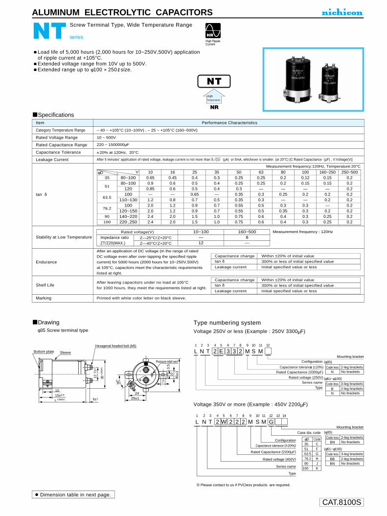
CAT.8100S
Pressure relief vent
29±1
45±110
3.5
24
7 +
30°
Sleeve Bottom plate
6±1
12.7
±1
35 +
2MA
X
Hexagenal headed bolt (M5)
L+3MAX.
15±0.5
10
L1
N2
T3
24
W5
26
27
28
M9
S10
M G11 12 13 14
Capacitance tolerance (±20%)Configuration
Case dia. code
Mounting bracket
(φ35)
(φ51~φ100)
φD
Rated Capacitance (2200µF)
Rated voltage (450V)
Series name
Type
5163.576.290
100
F35 C
GHJK
Code
Code lessBB
3-leg brackets2-leg brackets
BN No brackets
Code less 2-leg bracketsBN No brackets
ALUMINUM ELECTROLYTIC CAPACITORS
NT series
Screw Terminal Type, Wide Temperature Range
Load life of 5,000 hours (2,000 hours for 10~250V,500V) applicationof ripple current at +105°C.Extended voltage range from 10V up to 500V.Extended range up to φ100 × 250Rsize.
Specifications
Category Temperature Range
Rated Voltage Range
Rated Capacitance Range
Capacitance Tolerance
Leakage Current
tan δ
Stability at Low Temperature
Endurance
Shelf Life
Marking
Performance CharacteristicsItem
– 40 ~ +105°C (10~100V) , – 25 ~ +105°C (160~500V)
10 ~ 500V
220 ~ 1500000µF
±20% at 120Hz, 20°C
After 5 minutes’ application of rated voltage, leakage current is not more than (µA) or 5mA, whichever is smaller. (at 20°C) [C:Rated Capacitance (µF) , V:Voltage(V)]
Printed with white color letter on black sleeve.
Measurement frequency:120Hz, Temperature:20°C
After an application of DC voltage (in the range of rated
DC voltage even after over-lapping the specified ripple
current) for 5000 hours (2000 hours for 10~250V,500V)
at 105°C, capacitors meet the characteristic requirements
listed at right.
After leaving capacitors under no load at 105°C
for 1000 hours, they meet the requirements listed at right.
Type numbering systemVoltage 250V or less (Example : 250V 3300µF)
Voltage 350V or more (Example : 450V 2200µF)
NT
NR
Measurement frequency : 120Hz
Z—25°C/Z+20°C
Z—40°C/Z+20°C
Rated voltage(V)
Impedance ratioZT/Z20(MAX.)
10~100—12
160~5008—
Capacitance change
Leakage current
tan δWithin ±20% of initial value
Initial specified value or less
300% or less of initial specified value
Capacitance change
Leakage current
tan δWithin ±20% of initial value
Initial specified value or less
300% or less of initial specified value
HighTemperature
35
51
63.5
76.2
90
100
φD 100.650.90.85—1.22.02.02.42.4
160.450.60.6—0.81.21.22.02.0
250.40.50.5
0.650.70.90.91.51.5
350.30.40.4—0.50.70.71.01.0
500.250.250.3
0.350.350.550.550.750.75
630.250.25—0.30.30.50.50.60.6
800.20.2—
0.25—0.30.350.40.4
1000.120.15—0.2—0.30.30.30.3
160~2500.150.15—0.20.2—0.20.250.25
250~5000.20.20.20.20.20.20.20.20.2
80~10080~100
120100
110~130100
120~150140~220220 , 250
VL
φ35 Screw terminal type
Drawing
L1
N2
T3
24
E5
36
37
28 12
M9
S10
M11
ConfigurationMounting bracket
Capacitance tolerancce (±20%) Rated Capacitance (3300µF)
Rated voltage (250V) Series name
Type
(φ35)
(φ51~φ100)
Code lessB
3-leg brackets2-leg brackets
N No brackets
Code less 2-leg bracketsN No brackets
3 CV
Dimension table in next page.
Please contact to us if PVCless products are required.

CAT.8100S
P
7
5
Pressure relief vent
Pressure relief vent
A±2
120°
30°
SleeveBottom plate
W± 1
D +
2MA
X
Hexagenal headed bolt
P±2
BT
U
S
L+ MAX.
H±1
±1
h
US
P A± 2
T
L+3MAX.
L+3MAX.
74.4
88.2
65.7
Sleeve Resin bushing Hexagenal headed bolt
120
105
Bottom plate
Sleeve Resin bushing Hexagenal headed boltBottom plate
83.7
95.5
φ4.5
Pressurerelief vent
31.8
±1
120°
63.5
57.5
Pressurerelief vent
31.8
±1
φ6.0
102.
5
Screw terminal type for φ 51 and larger Method to mount resin bushing (φ76.2) (Apply to L=150 or more)
Method to mount resin bushing (φ90) (Apply to L=150 or more)
Dimension of terminal pitch (W) and length (R) and Nominal dia.of bolt
Dimensions of mounting bracket
(mm)
(mm)
P
A
T
S
U
°
H
h
φD
51.5
63.5
76.2
90.5
100.50
W22.0
28.6
31.8
31.8
41.5
R
6
6
6
6
10
α33334
Nominal.of boltM5
M5
M5
M5
M8
51
32.5
38.5
7.5
5.0
12
60
20
15
63.5
38.1
43
8.0
5.0
14
60
25
20
76.2
44.5
49.2
7.0
5.0
14
60
30
24
90
50.8
58.5
8.0
5.0
16
60
35
25
100
56.3
62
8.0
5.0
16
60
36
30
51
33.2
40
6.0
4.5
14
30
25
15
63.5
40.5
46.5
7.0
4.5
14
30
35
20
76.2
46.5
53
6.0
4.5
14
30
35
20
90
53
59
6.0
4.5
14
30
35
20
3-Legs 2-Legs
SymbolφD
Leg Shape
NT series
ALUMINUM ELECTROLYTIC CAPACITORS
∗B
3-leg brackets for φ90 capacitors have different
hole shapes from the ordinary ones as illustrated
below.P
5
7
Dimensions D × L (mm)
10000
15000
22000
33000
47000
68000
100000
150000
220000
330000
470000
680000
1000000
1500000
103
153
223
333
473
683
104
154
224
334
474
684
105
155
Cap.(µF) Code Case size Rated ripple Case size Rated ripple Case size Case sizeRated ripple Rated ripple
Surge
V(Code)
35 × 80
35 × 100
51 × 80
51 × 100
51 × 120
63.5 × 120
76.2 × 120
90 × 140
90 × 170
90 × 220
100 × 220
13V
10V (1A)
4.8
6.2
6.8
8.6
10.8
13.2
15.8
17.0
18.4
20.1
22.1
35 × 80
35 × 100
51 × 80
51 × 100
51 × 120
63.5 × 120
76.2 × 120
90 × 140
90 × 170
90 × 220
100 × 250
5.2
6.8
7.1
9.6
11.0
14.1
20.6
22.1
24.0
26.1
28.8
35 × 80
35 × 100
51 × 80
51 × 120
63.5 × 100
63.5 × 120
76.2 × 120
90 × 140
90 × 170
90 × 220
100 × 220
35 × 80
35 × 80
35 × 100
51 × 80
51 × 100
51 × 120
63.5 × 120
76.2 × 120
90 × 140
90 × 170
90 × 220
100 × 250
4.9
6.2
8.3
10.2
11.5
13.8
17.0
20.8
22.4
24.2
26.4
4.7
5.1
5.6
7.4
8.4
12.3
13.6
15.1
17.4
21.3
25.4
27.5
20V
16V (1C) 25V (1E) 35V (1V)
32V 44V
Rated Ripple (A rms) at 105°C 120Hz

CAT.8100S
450V (2W) 500V (2H) 550V
Frequency coefficient of rated ripple current
10~100V160~250V350~500V
600.900.880.82
1201.001.001.00
3601.081.081.20
1k1.151.151.35
10k~1.151.201.40
Coeff.
Frequency (Hz)
ALUMINUM ELECTROLYTIC CAPACITORS
NT series
2200330047006800
100001500022000330004700068000
100000150000220000330000470000
222332472682103153223333473683104154224334474
Cap.(µF) Code Case size Rated ripple Case size Rated ripple Case size Case sizeRated ripple Rated rippleSurge
V(Code)
35 × 8035 × 10051 × 8051 × 120
63.5 × 10063.5 × 12076.2 × 120
90 × 14090 × 17090 × 220
100 × 250
63V50V (1H)
4.95.56.38.09.9
12.816.819.522.024.326.1
35 × 10051 × 8051 × 100
63.5 × 10063.5 × 12076.2 × 120
90 × 14090 × 17090 × 220
100 × 250
5.05.96.99.4
11.213.517.821.023.726.1
35 × 8035 × 10051 × 8051 × 100
63.5 × 10076.2 × 10076.2 × 120
90 × 14090 × 17090 × 220
100 × 250
35 × 8035 × 8035 × 10051 × 8051 × 100
63.5 × 10076.2 × 10076.2 × 140
90 × 14090 × 17090 × 220
100 × 220
3.53.95.46.48.49.9
13.417.018.621.624.8
2.43.33.85.26.77.89.9
12.717.018.220.623.4
79V63V (1J) 80V (1K) 100V (2A)
100V 125V
D × L (mm)
680100015002200330047006800
100001500022000330004700068000
681102152222332472682103153223333473683
Cap.(µF) Code Case size Rated ripple Case size Rated ripple Case size Rated rippleSurge
V(Code)
35 × 8035 × 8035 × 10051 × 8051 × 100
63.5 × 10063.5 × 12076.2 × 12076.2 × 140
90 × 14090 × 220
100 × 250
200V160V (2C)
1.62.12.73.84.56.87.89.8
12.513.417.219.2
35 × 8035 × 10051 × 8051 × 100
63.5 × 10063.5 × 12076.2 × 12076.2 × 140
90 × 14090 × 22090 × 250
1.72.32.93.95.17.08.2
10.415.116.619.9
35 × 8035 × 10051 × 8051 × 100
63.5 × 10063.5 × 12076.2 × 120
90 × 14090 × 17090 × 220
100 × 250
1.41.92.43.24.35.97.19.6
12.715.417.0
250V200V (2D) 250V (2E)
300V
220330470680
100015002200
2700
3300
3900
4700
5600
6800
8200
10000120001500022000
221331471681102152222
272
332
392
472
562
682
822
103123153223
Cap.(µF) Code Case size Rated ripple Case size Rated ripple Case size Rated rippleSurge
V(Code)
35 × 8035 × 8051 × 8051 × 8051 × 10051 × 120
63.5 × 100
63.5 × 110
63.5 × 130
63.5 × 15076.2 × 12063.5 × 17076.2 × 130
76.2 × 150
76.2 × 17090 × 15090 × 15090 × 19090 × 220
100 × 250
400V350V (2V)
2.12.84.16.58.6
11.012.7
14.4
16.8
19.819.722.722.2
26.2
30.329.332.436.042.948.0
35 × 8035 × 8035 × 10051 × 8051 × 8051 × 120
63.5 × 10063.5 × 110
63.5 × 130
63.5 × 15076.2 × 11063.5 × 17076.2 × 130
76.2 × 150
76.2 × 17090 × 150
90 × 17090 × 19090 × 220
100 × 220
1.62.33.14.26.69.1
11.513.1
15.4
17.918.220.720.3
23.7
27.626.9
31.032.938.344.5
35 × 8035 × 10051 × 8051 × 10051 × 10051 × 120
63.5 × 11063.5 × 13076.2 × 11063.5 × 15076.2 × 13063.5 × 170
76.2 × 150
76.2 × 19090 × 150
90 × 170
90 × 19090 × 22090 × 23090 × 250
1.82.43.44.47.09.2
11.813.814.516.517.118.3
21.7
26.424.1
28.3
32.535.139.245.6
450V400V (2G)
500V
Rated Ripple (A rms) at 105°C 120Hz
Case size Rated ripple
51 × 8051 × 8051 × 10051 × 120
63.5 × 11063.5 × 13063.5 × 15076.2 × 13063.5 × 17076.2 × 150
76.2 × 15076.2 × 190
90 × 150
90 × 150
90 × 170
90 × 22090 × 250
2.73.24.25.57.19.3
11.011.012.913.0
14.117.216.3
17.8
20.7
25.529.9
Dimensions

CAT.8100S
After an application of DC voltage (in the range of rated voltage even after over-lapping the standard ripple current) for 20,000 hours at 85°C, capacitors shall meet thecharacteristics requirements indicated at right. (2000 hours at 85°C for the parts rated at 630V, 5000 hours at 85°C for the parts rated at 500V and 550V) After an application of DC voltage (in the range of rated DC voltage even afterover-lapping the maximum allowable ripple current) for 5000 hours at 85°C,capacitors meet the characteristic requirements listed at right.
ALUMINUM ELECTROLYTIC CAPACITORS
NX
Longer life
NX series
Screw Terminal Type, High ripple longer life.
Suited for use in industrial power supplies for inverter circuitry, etc.High ripple current, extra-high voltage application.High reliability, long life for 20,000 hours application of ripplecurrent at +85°C.Extended range up to φ100 × 250Rsize.Flame retardant electroly to type available.Bushing type for better vibration and insulation also available.
L+3MAX.
L+3MAX.
74.488
.2
65.7
Sleeve Resin bushing Hexagenal headed bolt
120
105
Bottom plate
Sleeve Resin bushing Hexagenal headed boltBottom plate
83.7
95.5
φ4.5
Pressurerelief vent
31.8
±1
120°
63.5
57.5
Pressurerelief vent
31.8
±1
φ6.0
102.
5
Specifications
Category Temperature RangeRated Voltage RangeRated Capacitance RangeCapacitance Tolerance
Leakage Current
tan δ
Stability at Low Temperature
Endurance
Shelf LifeMarking
Performance CharacteristicsItem
– 25 ~ +85°C350 ~ 630V
1000 ~ 27000µF
±20% at 120Hz, 20°C
After 5 minutes' application of rated voltage, leakage current is not more than (µA) or 5 mA, whichever is smaller (at 20°C).[C : Rated Capacitance(µF), V : Voltage ( V ) ]
After leaving capacitors under no load at 85°C for 1000 hours, they meet the specified value for endurance characteristics listed above.
See P199 (Measurement frequency:120Hz, Temperature:20°C)
Rated voltage (V) 350 ~ 630Z—25°C/Z+20°C
8Impedance ratio ZT/Z20(MAX.)
Measurement frequency : 120Hz
Printed with white color letter on black sleeve.
P
7
5
Pressure relief vent
Pressure relief vent
A±2
120°
30°
SleeveBottom plate
W± 1
D +
2MA
X
Hexagenal headed bolt
P±2
BT
U
S
L+ MAX.
H±1
±1
h
US
P A± 2
T
DrawingMethod mount metal bracket
Dimension table in next page.
B3-leg brackets for φ90 capacitors have differenthole shapes from the ordinary ones illustratedbelow.
φD W R α Nominal dia. of bolt51 22.0 6 3 M 563.5 28.6 6 3 M 576.2 31.8 6 3 M 590 31.8 6 3 M 5
100 41.5 10 4 M 8
Dimension of terminal pitch (W) and length (R) and Nominal dia. of (mm)
NR
Type numbering system (Example : 450V 2200µF)
L1
N2
X3
24
W5
26
27
28
M9
S10
M11 12 13 14
Capacitance tolerance(±20%)
Configuration
Case dia. code
Mounting bracket
φD
Rated Capacitance(2200µF)
Rated voltage(450V)
Series name
Type
5163.576.2
Code lessBBBN
3-leg brackets2-leg bracketsNo brackets
90100
FGHJK
Code
Resin bushing available upon request.
Method to mount resin bushing (φ76.2 ) (Apply to L=150 or more)
Method to mount resin bushing (φ90) (Apply to L=150 or more)
Capacitance changetan δLeakage current
Within ±20% of initial value300% or less of initial specified valueInitial specified value or less
3 CV
Please contact to us if PVCless products are required.
7.5 8.0 7.0 8.0 8.0 6.0 7.0 6.0 6.05.0 5.0 5.0 5.0 5.0 4.5 4.5 4.5 4.5
14 14 14 1430 30 30 30
51 63.5 76.2 90 100 51 63.5 76.2 9032.5 38.1 44.5 50.8 56.3 33.2 40.5 46.5 5338.5 43 49.2 58.5 62 40 46.5 53 59
20 25 30 35 36 25 35 35 3515 20 24 25 30 15 20 20 20
12 14 14 18 16 60 60 60 60 60
Dimension of mounting bracket
PA
Hh
TSU
°
3--Leg 2--LegSymbol
Leg shape
φD
(mm)

CAT.8100S
ALUMINUM ELECTROLYTIC CAPACITORS
NX series
Dimensions
Ripple (A rms) at 85°C 120Hz
( 1) • Standard ripple current:Ripple current value allowable for the life time of 20,000 hours at 85°C.(5,000 hours at 85°C for the voltage rating of 500V and 550V).
( 2) • Maximum rated ripple current:Ripple current value allowable for the life time of 5,000 hours at 85°C.
• Estimated life time of capacitor is calculated by the following formula, taking the operating temperature, inner temperature rise due to the ripple and derated voltage into consideration.
Ln = L0 × 2 × 2 × αWhere,
Ln : Lifetime under normal operating conditions.(h)Lo : Lifetime under maximum operating temperature of 85°C and applied DC
voltage. (28000h)T : Ambient temperature.(°C)∆T : Inner temperature rise of capacitor due to ripple current(°C)K : Acceleration coefficient for temperature rise due to the ripple current.
when T+∆T 90°C,K=10
when T+∆T>90°C, K=2.5α : Life factor
— ∆T K
• Life factor α due to the voltage derating shall be decided by the temperature and the applied voltage
( 3) Leakage current:I= ×10—3 or 5mA, whichever the smaller.I : Leakage Current (mA)C : Rated Capacitance (µF)V : Voltage (V)
• 3-leg bracket is furnished as standard.In case no-bracket or 2-leg bracket required, please put BN or BB at the and of typenumber.
Ex. 3-leg bracket LNX2G472MSMH2-leg bracket LNX2G472MSMHBBNo bracket LNX2G472MSMHBN
• Flame-retardant type electrolyte is also available.Please contact to Nichicon representative for the rated ripple current value.
Frequency coefficient of rated ripple current
Coefficient 0.82 1.00 1.20 1.35 1.40
Oper.temp. T 70°C 70°C<T 85°C— V/Vo 0.8 0.8<V/Vo 0.9 0.9<V//Vo 1.01.0 1.0 0.8 0.7
Voltage ratioα
Frequency (Hz) 60 120 360 1k 10k~
10001200150018002200
2700
3300
3900
4700
5600
6800
8200
10000
12000
15000180002200027000
1000120015001800
2200
2700
3300
3900
4700
5600
6800
8200
10000
12000150001800022000
3.54.24.95.66.78.07.79.29.0
10.410.312.011.914.013.516.316.018.718.221.821.325.124.829.032.438.042.03.84.55.36.07.06.88.28.19.69.3
11.010.512.612.314.714.316.716.319.319.022.722.225.529.633.041.4
Standardripple
(Arms) 1
4.65.36.37.38.8
10.39.9
12.111.812.512.214.814.017.016.419.619.122.021.425.525.329.128.836.039.743.247.05.05.86.88.29.38.9
10.810.612.912.414.413.916.616.018.818.321.220.724.123.728.328.031.937.040.544.7
Maximum rated ripple(Arms) 2
0.20.20.20.20.20.20.20.20.20.20.20.20.20.20.20.20.20.20.20.20.20.20.20.20.20.20.20.20.20.20.20.20.20.20.20.20.20.20.20.20.20.20.20.20.20.20.20.20.20.20.20.20.2
tan δ(MAX)
1.771.942.172.382.632.922.923.223.223.503.503.853.854.204.204.634.635.005.005.005.005.005.005.005.005.005.001.902.082.322.552.812.813.123.123.453.453.753.754.114.114.494.494.954.955.005.005.005.005.005.005.005.00
Leakagecurrent
(mA MAX) 3
Case sizeφ D×L(mm) Code
350V(400) (2V)
400V(450)(2G)
V(Surge) (Code)
Cap.(µF)
51 × 60051 × 70051 × 80051 × 90051 × 11051 × 130
63.5 × 90051 × 150
63.5 × 10063.5 × 11076.2 × 90063.5 × 13076.2 × 10063.5 × 15076.2 × 11063.5 × 17076.2 × 13076.2 × 150
90 × 13076.2 × 170
90 × 15076.2 × 190
90 × 15090 × 19090 × 220
100 × 220100 × 250
51 × 70051 × 80051 × 10051 × 11051 × 130
63.5 × 90063.5 × 11076.2 × 90063.5 × 13076.2 × 10063.5 × 15076.2 × 10063.5 × 17076.2 × 13063.5 × 19076.2 × 15076.2 × 170
90 × 13076.2 × 190
90 × 15076.2 × 220
90 × 17090 × 190
100 × 190100 × 220100 × 250
LNX2V102MSMFLNX2V122MSMFLNX2V152MSMFLNX2V182MSMFLNX2V222MSMFLNX2V272MSMFLNX2V272MSMGLNX2V332MSMFLNX2V332MSMGLNX2V392MSMGLNX2V392MSMHLNX2V472MSMGLNX2V472MSMHLNX2V562MSMGLNX2V562MSMHLNX2V682MSMGLNX2V682MSMHLNX2V822MSMHLNX2V822MSMJLNX2V103MSMHLNX2V103MSMJLNX2V123MSMHLNX2V123MSMJLNX2V153MSMJLNX2V183MSMJLNX2V223MSMKLNX2V273MSMKLNX2G102MSMFLNX2G122MSMFLNX2G152MSMFLNX2G182MSMFLNX2G222MSMFLNX2G222MSMGLNX2G272MSMGLNX2G272MSMHLNX2G332MSMGLNX2G332MSMHLNX2G392MSMGLNX2G392MSMHLNX2G472MSMGLNX2G472MSMHLNX2G562MSMGLNX2G562MSMHLNX2G682MSMHLNX2G682MSMJLNX2G822MSMHLNX2G822MSMJLNX2G103MSMHLNX2G103MSMJLNX2G123MSMJLNX2G153MSMKLNX2G183MSMKLNX2G223MSMK
100012001500
1800
2200
2700
3300
3900
4700
5600
6800
8200
10000120001500018000100012001500180022002700330039004700560068008200
1000012000100012001500180022002700330039004700560068008200
100001000120015001800220027003300390047005600
4.04.75.46.46.17.27.18.68.3
10.09.7
11.411.213.012.915.415.317.317.120.319.823.026.931.137.0
4.24.85.56.57.78.8
10.412.113.715.918.521.423.827.8
4.35.06.06.78.09.4
11.012.514.516.619.521.625.2
5.96.78.19.6
10.712.614.717.321.424.7
Standardripple
(Arms) 1
5.26.37.38.77.69.69.4
11.311.013.312.915.114.617.316.919.419.122.021.625.725.429.633.538.041.3—————————————————————————————————————
Maximumrated ripple(Arms) 2
0.20.20.20.20.20.20.20.20.20.20.20.20.20.20.20.20.20.20.20.20.20.20.20.20.20.20.20.20.20.20.20.20.20.20.20.20.20.20.20.20.20.20.20.20.20.20.20.20.20.20.20.20.30.30.30.30.30.30.30.30.30.3
tan δ(MAX)
2.012.202.462.702.702.982.983.313.313.663.663.973.974.364.364.764.765.005.005.005.005.005.005.005.002.122.322.602.853.153.493.854.194.605.005.005.005.005.002.222.442.722.983.303.664.044.394.825.005.005.005.002.382.612.923.193.533.914.334.705.005.00
Leakagecurrent
(mA MAX) 3
Case sizeφ D×L(mm) Code
450V(500) (2W)
500V(550) (2H)
550V(600) (2L)
630(680) (2J)
V(Surge) (Code)
Cap.(µF)
51 × 80051 × 10051 × 11051 × 130
63.5 × 90063.5 × 11076.2 × 90063.5 × 13076.2 × 10063.5 × 15076.2 × 11063.5 × 17076.2 × 13063.5 × 19076.2 × 15076.2 × 170
90 × 15076.2 × 190
90 × 15076.2 × 220
90 × 17090 × 19090 × 220
100 × 220100 × 250
51 × 11063.5 × 90063.5 × 90063.5 × 11063.5 × 13076.2 × 11076.2 × 13076.2 × 150
90 × 13090 × 15090 × 17090 × 190
100 × 190100 × 220
51 × 13063.5 × 11063.5 × 13076.2 × 11076.2 × 13076.2 × 15076.2 × 170
90 × 15090 × 17090 × 19090 × 220
100 × 220100 × 25063.5 × 13076.2 × 11076.2 × 13076.2 × 150
90 × 13090 × 15090 × 17090 × 190
100 × 220100 × 250
LNX2W102MSMFLNX2W122MSMFLNX2W152MSMFLNX2W182MSMFLNX2W182MSMGLNX2W222MSMGLNX2W222MSMHLNX2W272MSMGLNX2W272MSMHLNX2W332MSMGLNX2W332MSMHLNX2W392MSMGLNX2W392MSMHLNX2W472MSMGLNX2W472MSMHLNX2W562MSMHLNX2W562MSMJLNX2W682MSMHLNX2W682MSMJLNX2W822MSMHLNX2W822MSMJLNX2W103MSMJLNX2W123MSMJLNX2W153MSMKLNX2W183MSMKLNX2H102MSMFLNX2H122MSMGLNX2H152MSMGLNX2H182MSMGLNX2H222MSMGLNX2H272MSMHLNX2H332MSMHLNX2H392MSMHLNX2H472MSMJLNX2H562MSMJLNX2H682MSMJLNX2H822MSMJLNX2H103MSMKLNX2H123MSMKLNX2L102MSMFLNX2L122MSMGLNX2L152MSMGLNX2L182MSMHLNX2L222MSMHLNX2L272MSMHLNX2L332MSMHLNX2L392MSMJLNX2L472MSMJLNX2L562MSMJLNX2L682MSMJLNX2L822MSMKLNX2L103MSMKLNX2J102MSMGLNX2J122MSMHLNX2J152MSMHLNX2J182MSMHLNX2J222MSMJLNX2J272MSMJLNX2J332MSMJLNX2J392MSMJLNX2J472MSMKLNX2J562MSMK
85-T10
V : Applied voltage(V) Vo : Rated voltage(V)
3 CV
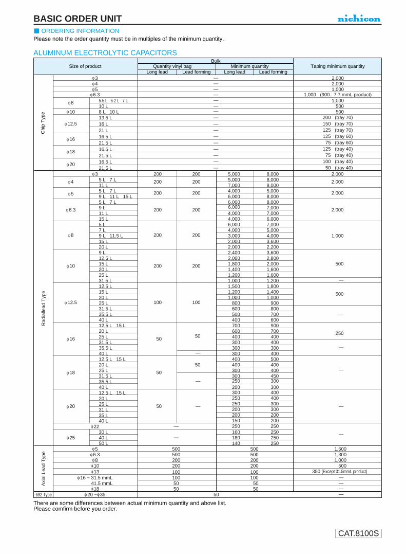
CAT.8100S
BASIC ORDER UNITORDERING INFORMATION
Please note the order quantity must be in multiples of the minimum quantity.
There are some differences between actual minimum quantity and above list.Please comfirm before you order.
ALUMINUM ELECTROLYTIC CAPACITORS
Chi
pT
ype
BulkSize of product Quantity vinyl bag Minimum quantity Taping minimum quantity
Long lead Lead forming Long lead Lead formingφ3 — 2,000φ4 — 2,000φ5 — 1,000φ6.3 — 1,000 (900 : 7.7 mmL product)
φ8 5.5 L 6.2 L 7 L — 1,00010 L — 500
φ10 8 L 10 L — 50013.5 L — 200 (tray 70)
φ12.5 16 L — 150 (tray 70)21 L — 125 (tray 70)
φ16 16.5 L — 125 (tray 60)21.5 L — 75 (tray 60)
φ18 16.5 L — 125 (tray 40)21.5 L — 75 (tray 40)
φ20 16.5 L — 100 (tray 40)21.5 L — 50 (tray 40)
φ3 200 200 5,000 8,000 2,000
φ4 5 L 7 L 200 200 5,000 8,000 2,00011 L 7,000 8,000
φ55 L 7 L 200 200 4,000 5,000 2,0009 L 11 L 15 L 6,000 8,0005 L 7 L 6,000 8,000
φ6.3 9 L 200 2006,000 7,000
11 L 4,000 7,0002,000
15 L 4,000 6,0005 L 6,000 7,0007 L 4,000 5,000
φ8 9 L 11.5 L 200 200 3,000 4,000 1,00015 L 2,000 3,60020 L 2,000 2,2009 L 2,400 3,60012.5 L 2,000 2,800
φ10 15 L 200 200 1,800 2,000 50020 L 1,400 1,60025 L 1,200 1,60031.5 L 1,000 1,200 —12.5 L 1,500 1,80015 L 1,200 1,400 50020 L 1,000 1,000
φ12.5 25 L 100 100 800 90031.5 L 600 80035.5 L 500 700 —40 L 400 60012.5 L 15 L 700 90020 L 600 700 250
φ16 25 L 5050 400 400
31.5 L 300 40035.5 L 300 300 —40 L — 300 40012.5 L 15 L 400 50020 L 50 400 400
φ18 25 L 50 300 400 —31.5 L 300 45035.5 L — 250 30040 L 200 30012.5 L 15 L 300 40020 L 250 400
φ20 25 L 50 — 250 300 —31 L 200 30035 L 200 20040 L 150 200
φ22 — 250 25030 L 160 250
φ25 40 L — 180 250—
50 L 140 250φ5 500 500 1,600φ6.3 500 500 1,300φ8 200 200 1,000φ10 200 200 500φ13 100 100 350 (Except 31.5mmL product)
φ16 ~ 31.5 mmL 100 100 —41.5 mmL 50 50 —φ18 50 50 —
φ20 ~φ35 50 —
Rad
ialle
adT
ype
Axi
alLe
adT
ype
692 Type

CAT.8100S
PB series
Miniature Sized, High Ripple Current High Reliability
High ripple current and highly dependable product withstandingload life of 5000 / 7000 hours at +105°C.Suited for ballast application.
ALUMINUM ELECTROLYTIC CAPACITORS
U1
P2
B3
24
C5
26
27
08
M9
P10
D11
Configuration
Capacitance tolerance (±20%)
Rated Capacitance (22µF)
Rated voltage (160V)
Series name
Type
φD
P
φd
5
2.0
0.5
6.3
2.5
0.5
8
3.5
0.6
10
5.0
0.6
12.5
5.0
0.6
16
7.5
0.8
18
7.5
0.8
P±0
.5
15MIN 4MIN
φD+
M
AX
φd
Pressurerelief vent(φ6.3up)
Radial Lead Type Type numbering system (Example : 160V 22µF)
12
Case Size Code
0.5 0.5 0.5 0.5 0.5 0.5 0.50.5 0.5 0.5 0.5 0.5 1.0 1.0
22
10.0
1.0
25
12.5
1.0
(φD 22) 2.0
(φD 18) 1.5
L + MAX
Sleeve (P.E.T.)
φ D
5
Pb free lead finishingPb free PET sleeve
Sn-Pb lead finishingPVC sleeve contain Pb
DD DH
6.3 ED EH
8 · 10 PD PH
12.5 ~ 18 HD HH
22 · 25 RD RH
Configuration
Please contact to us if other configurations are required.
Dimension table in next page.
Please refer to page 19, 20, 21 about the formed or taped product spec.Please refer to page 3 for the minimum order quantity.
Specifications
Category Temperature Range
Rated Voltage Range
Rated Capacitance Range
Capacitance Tolerance
Leakage Current
tan δ
Stability at Low Temperature
Endurance
Shelf Life
Marking
Performance CharacteristicsItem
–40 ~ +105°C (10 ~ 50V), –25 ~ +105°C (160 ~ 450V)
10 ~ 450V
0.47 ~ 3300µF
±20% at 120Hz, 20°C
Rated Voltage (V) 10 ~ 50V 160 ~ 450V
———After 2 minutes' application of ratedvoltage, leakage current is not more than0.01CV or 3 (µA) , whichever is greater.
After 2 minutes' application of ratedvoltage, leakage current is not more than0.06CV+10 (µA) , whichever is greater.
Printed with white color letter on dark brown sleeve.
After leaving capacitors under no load at 105°C for 1000 hours, they meet the specified value for endurance characteritics listed above.
Measurement frequency : 120Hz
Capacitance change
Leakage current
After an application of D.C. bias voltage plus the ratedripple current for 5000 hours (φ10 · φ12.5 (10 ~ 50V) :7000 hours) at 105°C the peak voltage shall notexceed the rated D.C. voltage, capacitors meet thecharacteristic requirements listed at right.
tan δ
Within ±30% of initial value (10 ~ 50V) Within ±20% of initial value (160 ~ 450V)
Initial specified value or less
300% or less of initial specified value (10 ~ 50V)200% or less of initial specified value (160 ~ 450V)
Z–25°C / Z+20°CRated voltage (V)
Impedance ratio ZT / Z20 (MAX.)103
162
252
352
502
1603
2003
2503
3504
4006
4506
Measurement frequency : 120Hz, Temperature : 20°C
Rated voltage (V)tan δ (MAX.)
100.30
160.25
250.22
500.15
1600.15
2000.15
2500.15
3500.20
4000.24
4500.24
350.18
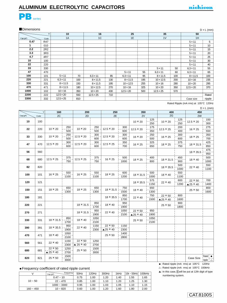
CAT.8100S
0.4712.23.34.7
10223347
100220330470
100022003300
R470102R23R34R7100220330470101221331471102222332
Cap.(µF)
V
1A
101C
161E
251V
351H
50
Code
Dimensions
5 × 116.3 × 11
8 × 11.58 × 11.5
10 × 1612.5 × 2012.5 × 25
70100150180350550810
6.3 × 118 × 11.58 × 11.5
10 × 12.510 × 20
12.5 × 25
85130195270430710
5 × 116.3 × 11
8 × 11.510 × 12.510 × 16
12.5 × 20
5595
195255325500
5 × 116.3 × 11
8 × 11.510 × 12.510 × 1610 × 20
12.5 × 25
5060
100200280350570
5 × 115 × 115 × 115 × 115 × 115 × 115 × 11
6.3 × 116.3 × 11
8 × 11.510 × 1610 × 20
12.5 × 20
Case size
51015202530405565
100235295370
Ratedripple
D × L (mm)
Rated Ripple (mA rms) at 105°C 120Hz
PB series
ALUMINUM ELECTROLYTIC CAPACITORS
Frequency coefficient of rated ripple currentV
0.47 ~ 100 0.750022 ~ 47001000 ~ 3300
010 ~ 820
50Hz
0.850.950.60
1.00120Hz
1.001.001.00
1.20300Hz
1.101.031.20
1.401kHz
1.201.051.60
1.55 1.6510k ~ 50kHz 100kHz
1.25 1.301.10 1.151.80 2.00
10 ~ 50
160 ~ 450
Cap.(µF)Frequency
12.5 × 20
12.5 × 20
12.5 × 25
16 × 25
18 × 25
18 × 31.5
18 × 35.5
18 × 40
22 × 40
22 × 5025 × 40
25 × 50
300600300600350700
5001000
6001200
7501500
8501700
950190010502100
1150230014002800
10 × 20
12.5 × 20
16 × 20
16 × 25
18 × 25
18 × 31.5
18 × 35.5
18 × 40
22 × 40
22 × 5025 × 40
25 × 50
125250175350250500325650
400800
5001000575115065013007501500
950190010502100
10 × 20
12.5 × 25
16 × 25
18 × 25
18 × 31.5
18 × 35.5
18 × 40
22 × 40
22 × 5025 × 40
25 × 50
125250200400300600375750
450900500100055011006001200
80016009001800
12.5 × 20
16 × 25
18 × 25
18 × 31.5
18 × 35.5
18 × 40
22 × 40
22 × 5025 × 40
25 × 50
Case Size
15030027555035070042585047595050010005501100
70014008001600
Ratedripple
2C160
2D200
2E250
2V350
2G400
2W450V
Code
D × L (mm)
: Rated ripple (mA rms) at 105°C 120Hz
: Rated ripple (mA rms) at 105°C 100kHz
: In this case, 6 will be put at 12th digit of type
numbering system.
250500250500300600
375750
5501100
6501300
8501700
950190010502100115023001250270015003000
100
220
330
470
560
680
820
101
121
151
181
221
271
331
391
471
561
681
821
10
22
33
47
56
68
82
100
120
150
180
220
270
330
390
470
560
680
820
10 × 20
10 × 20
12.5 × 20
12.5 × 25
16 × 25
18 × 25
18 × 31.5
18 × 35.5
18 × 40
22 × 40
22 × 5025 × 40
25 × 50
10 × 20
12.5 × 20
12.5 × 20
12.5 × 25
16 × 25
18 × 25
18 × 31.5
18 × 31.5
18 × 40
22 × 40
22 × 5025 × 40
25 × 50
250500300600300600
375750
5501100
6501300
8501700
95019001050210011502300
1250270015003000
Cap.(µF)
Wider range of rating.

CAT.8100S
Pressurerelief vent
In case L >25 for the φ12.5 dia. unit, lead dia. φ d=0.8mm.
U1
P2
J3
14
E5
46
77
18
M9
H10
D11 12
Configuration
Case size code
Capacitance tolerance (±20%)
Rated Capacitance (470µF)
Rated voltage (25V)
Series name
Type
Type
15000
10000
6800
4700
3300
2200
1500
Frequency coefficientRated voltage
Small DiaLow Profile
Code
6
15MIN 4MIN
φ d
φD+
0.5
MA
X
P±0
.5
(φ6.3up)
φD
P
φd
5
2.0
0.5
6.3
2.5
0.5
8
3.5
0.6
10
5.0 5.0
0.6
12.5
0.6
16
7.5
0.8
18
7.5
0.8
(φD < 10) 1.0(φD 10) 1.5
L + MAX
Sleeve (P.E.T.)
φ D
5
Pb free lead finishingPb free PET sleeve
Sn-Pb lead finishingPVC sleeve contain Pb
DD DH
6.3 ED EH
8 • 10 PD PH
12.5 ~ 18 HD HH
Configuration
Please contact to us if other configurations are required.
ALUMINUM ELECTROLYTIC CAPACITORS
PJ series
Low Impedance, For Switching Power Supplies
Low impedance and high reliability withstanding 5000 hours load lifeat +105˚C (3000 / 2000 hours for smaller case sizes as specified below).Capacitance ranges available based on the numerical values in E12 series under JIS.Ideally suited for use of switching power supplies.
Specifications
Category Temperature RangeRated Voltage RangeRated Capacitance RangeCapacitance Tolerance
Leakage Current
tan δ
Stability at Low Temperature
Endurance
Marking
Performance CharacteristicsItem
–55 ~ +105˚C (6.3 ~ 100V), –40 ~ +105˚C (160 ~ 400V), –25 ~ +105˚C (450V)6.3 ~ 450V0.47 ~ 15000µF±20% at 120Hz, 20˚CRated Voltage (V)
Leakage current
For capacitance of more than 1000µF, add 0.02 for every increase of 1000µF. Measurement frequency : 120Hz, Temperature : 20˚C
120Hz
After 1 minute's application of rated voltage, leakage current is not more
than 0.03CV or 4 (µA), whichever is greater.
Printed with white color letter on dark brown sleeve.
After an application of D.C. bias voltage plus the rated ripplecurrent for 5000 hours (2000 hours for D = 5 and 6.3, 3000hours for D = 8 )at 105˚C the peak voltage shall not exceed therated D.C. voltage, capacitors meet the characteristicrequirements shown on the right.
Shelf LifeAfter leaving capacitors under no load at 105˚Cfor 1000 hours, they meet the characteristicrequirements listed at right.
160 ~ 450CV <= 1000 : I = 0.1CV+40 (µA) max. (1 minute's)
CV > 1000 : I = 0.04CV+100 (µA) max. (1 minute's)
Rated voltage (V)
Impedance
ratio
Z–55˚C / Z+20˚C
Z–40˚C / Z+20˚C
Z–25˚C / Z+20˚C
Rated Voltage (V)tan δ (MAX.)
6.30.22
6.3 • 104——
163——
25 • 353——
50 ~ 1002——
160 ~ 200—4—
250—6—
315 ~ 350—8—
400—10—
450——15
100.19
160.16
250.14
350.12
500.10
63 ~ 1000.08
160 ~ 3500.20
400 • 4500.25
Radial Lead Type
PJ PS
6.3 ~ 100
Type numbering system (Example : 25V 470µF)
Approved by Reliability Center for ElectronicComponent, Japan-Certification No. RCJ-03-23C
Dimension table in next pages.
Low ImpedanceHigh Ripple current
Leakage current
tan δCapacitance change
Initial specified value or less200% or less of initial specified valueWithin ±20% of initial value
Leakage current
tan δCapacitance change
Initial specified value or less150% or less of initial specified valueWithin ±20% of initial value
Please refer to page 19, 20, 21 about the formed or taped product spec.Please refer to page 3 for the minimum order quantity.
15000
10000
6800
4700
3300
2200
1500
1000
680
470
330
220
150
100
68
47
33
22
15
10
0.68
0.47
0 0.5 0.6 0.7 0.8 0.9 1.0Frequency coefficient
Cap
.(µF
)
300Hz 1kHz120Hz
Frequency coefficientRated voltage
6.3 ~ 100V
(10kHz ~ 200kHz = 1)
160 ~ 450V50Hz 120Hz 300Hz 1kHz 10kHz~
0.80 1.00 1.25 1.40 1.60
Frequency coefficient ofrated ripple current

CAT.8100S
PJ series
ALUMINUM ELECTROLYTIC CAPACITORS
Dimensions
2227333947566882
100120150180220270330390470560680820
100012001500180022002700330039004700560068008200
100001200015000
220270330390470560680820101121151181221271331391471561681821102122152182222272332392472562682822103123153
Cap. (µF)6.3 (0J) 35 (1V)
5 × 115 × 11
6.3 × 116.3 × 116.3 × 116.3 × 156.3 × 15
8 × 11.58 × 158 × 158 × 208 × 20
10 × 2010 × 2010 × 2510 × 31.510 × 31.5
12.5 × 2512.5 × 2512.5 × 31.512.5 × 35.512.5 × 40
16 × 31.516 × 35.516 × 4018 × 35.518 × 40
10 × 12.510 × 12.510 × 1510 × 15
12.5 × 1512.5 × 1512.5 × 15
16 × 1516 × 1518 × 1518 × 1516 × 2016 × 2518 × 2018 × 2518 × 31.518 × 35.5
D × L (mm)
5 × 115 × 11
6.3 × 116.3 × 116.3 × 116.3 × 116.3 × 156.3 × 15
8 × 11.58 × 158 × 158 × 208 × 20
10 × 2010 × 2010 × 2510 × 31.5
12.5 × 2012.5 × 2512.5 × 2512.5 × 31.512.5 × 35.512.5 × 40
16 × 31.516 × 35.516 × 4018 × 40
10 × 12.510 × 12.510 × 1510 × 15
12.5 × 1512.5 × 1512.5 × 15
16 × 1516 × 1518 × 1518 × 1516 × 2016 × 2518 × 2018 × 2518 × 31.518 × 35.5
25 (1E)
10 × 12.510 × 12.510 × 1510 × 15
12.5 × 1512.5 × 1512.5 × 15
16 × 1516 × 1518 × 1516 × 2016 × 2016 × 2518 × 2018 × 2518 × 31.518 × 35.5
16 (1C)
10 × 12.510 × 12.510 × 1510 × 15
12.5 × 1512.5 × 1512.5 × 15
16 × 1516 × 1518 × 1516 × 2016 × 2018 × 2018 × 2518 × 2518 × 31.518 × 35.5
5 × 115 × 11
6.3 × 116.3 × 116.3 × 116.3 × 116.3 × 156.3 × 15
8 × 11.58 × 158 × 158 × 208 × 20
10 × 2010 × 2010 × 2510 × 31.5
12.5 × 2012.5 × 2512.5 × 31.512.5 × 31.512.5 × 35.512.5 × 40
16 × 31.516 × 35.516 × 4018 × 35.518 × 40
— 6 — 6 — 6 — 6 — 610 (1A)
10 × 12.510 × 12.510 × 1510 × 15
12.5 × 1512.5 × 1512.5 × 15
16 × 1516 × 1518 × 1518 × 1516 × 2018 × 2018 × 2018 × 2518 × 31.518 × 31.5
5 × 115 × 11
6.3 × 116.3 × 116.3 × 116.3 × 116.3 × 156.3 × 15
8 × 11.58 × 158 × 158 × 208 × 20
10 × 2010 × 2010 × 2510 × 31.5
12.5 × 2012.5 × 2512.5 × 31.512.5 × 35.512.5 × 40
16 × 31.516 × 35.516 × 35.516 × 4018 × 40
5 × 115 × 11
6.3 × 116.3 × 116.3 × 116.3 × 116.3 × 156.3 × 15
8 × 11.58 × 158 × 158 × 208 × 20
10 × 2010 × 2010 × 2510 × 31.5
12.5 × 2012.5 × 2512.5 × 2512.5 × 31.512.5 × 35.512.5 × 40
16 × 31.516 × 35.516 × 4018 × 40
V (Code)Size codeCode
0.470.6811.52.23.34.76.8
101215182227333947566882
100120150180220270330390470560680820
10001200150018002200
R47R680101R52R23R34R76R8100120150180220270330390470560680820101121151181221271331391471561681821102122152182222
50 (1H)
5 × 115 × 115 × 115 × 115 × 115 × 115 × 115 × 115 × 115 × 115 × 115 × 11
6.3 × 116.3 × 116.3 × 116.3 × 116.3 × 156.3 × 15
8 × 11.58 × 158 × 208 × 20
10 × 2010 × 2010 × 2510 × 31.510 × 31.5
12.5 × 2512.5 × 2512.5 × 31.512.5 × 35.512.5 × 40
16 × 31.516 × 35.516 × 4018 × 35.518 × 40
5 × 115 × 115 × 115 × 115 × 115 × 11
6.3 × 116.3 × 116.3 × 116.3 × 116.3 × 156.3 × 15
8 × 11.58 × 158 × 158 × 20
10 × 2010 × 2010 × 2510 × 31.510 × 31.5
12.5 × 2512.5 × 2512.5 × 31.512.5 × 35.512.5 × 40
16 × 31.516 × 35.516 × 4018 × 35.518 × 40
10 × 12.510 × 12.510 × 15
12.5 × 1512.5 × 1512.5 × 15
16 × 1516 × 1516 × 1518 × 1516 × 2016 × 2518 × 2018 × 2518 × 31.518 × 35.5
100 (2A)
10 × 12.510 × 12.510 × 15
12.5 × 1512.5 × 1512.5 × 15
16 × 1516 × 1516 × 1518 × 1516 × 2016 × 2518 × 2018 × 2518 × 31.518 × 31.5
80 (1K)
10 × 12.510 × 12.510 × 15
12.5 × 1512.5 × 1512.5 × 15
16 × 1516 × 1518 × 1518 × 1516 × 2016 × 2518 × 2018 × 2518 × 31.518 × 35.5
5 × 115 × 11
6.3 × 116.3 × 116.3 × 116.3 × 116.3 × 156.3 × 15
8 × 11.58 × 158 × 158 × 20
10 × 2010 × 2010 × 2510 × 31.510 × 31.5
12.5 × 2512.5 × 31.512.5 × 31.512.5 × 35.512.5 × 40
16 × 31.516 × 35.516 × 4018 × 35.518 × 40
— 6 — 6 — 6 — 663 (1J)
10 × 12.510 × 1510 × 15
12.5 × 1512.5 × 1512.5 × 15
16 × 1516 × 1516 × 1518 × 1516 × 2016 × 2018 × 2018 × 2518 × 31.518 × 31.5
5 × 115 × 11
6.3 × 116.3 × 116.3 × 116.3 × 116.3 × 156.3 × 15
8 × 11.58 × 158 × 158 × 20
10 × 2010 × 2010 × 2510 × 31.5
12.5 × 2012.5 × 2512.5 × 2512.5 × 31.512.5 × 35.512.5 × 40
16 × 31.516 × 35.516 × 4018 × 40
V (Code)Size codeCode
In case of low profile type, will be put at 12th digit of type numbering system. 6
Cap. (µF)
Dimension table for 160 ~ 450V productsare shown in 138 page.
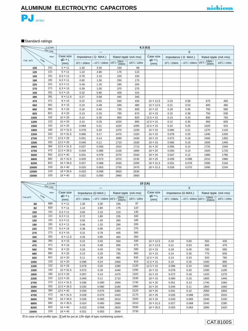
CAT.8100S
PJ series
ALUMINUM ELECTROLYTIC CAPACITORS
Standard ratings
V (Code)
Case size φD × L(mm)
Case size φD × L(mm)
Impedance ( Ω MAX.) Impedance ( Ω MAX.)Rated ripple (mA rms) Rated ripple (mA rms)
— 6
20˚C / 100kHz 20˚C / 100kHz–10˚C / 100kHz –10˚C / 100kHz105˚C / 120Hz 105˚C / 120Hz
I tem
Size code
100
120
150
180
220
270
330
390
470
560
680
820
1000
1200
1500
1800
2200
2700
3300
3900
4700
5600
6800
8200
10000
12000
15000
101
121
151
181
221
271
331
391
471
561
681
821
102
122
152
182
222
272
332
392
472
562
682
822
103
123
153
5 × 11
5 × 11
6.3 × 11
6.3 × 11
6.3 × 11
6.3 × 15
6.3 × 15
8 × 11.5
8 × 15
8 × 15
8 × 20
8 × 20
10 × 20
10 × 20
10 × 25
10 × 31.5
10 × 31.5
12.5 × 25
12.5 × 25
12.5 × 31.5
12.5 × 35.5
12.5 × 40
16 × 31.5
16 × 35.5
16 × 40
18 × 35.5
18 × 40
1.40
1.10
0.78
0.60
0.48
0.39
0.32
0.27
0.22
0.19
0.16
0.13
0.12
0.10
0.084
0.078
0.066
0.051
0.045
0.037
0.034
0.031
0.029
0.027
0.025
0.023
0.022
3.50
2.80
2.10
1.50
1.20
1.00
0.80
0.68
0.55
0.48
0.40
0.33
0.30
0.25
0.21
0.20
0.17
0.14
0.11
0.093
0.085
0.078
0.073
0.068
0.063
0.058
0.055
150
175
225
250
285
370
405
445
550
595
730
795
950
1020
1220
1370
1470
1590
1710
1910
2100
2270
2370
2550
2750
2820
2960
99
115
155
175
205
275
310
345
435
480
605
670
820
895
1090
1230
1320
1430
1530
1710
1890
2040
2130
2290
2470
2530
2660
10 × 12.5
10 × 12.5
10 × 15
10 × 15
12.5 × 15
12.5 × 15
12.5 × 15
16 × 15
16 × 15
18 × 15
18 × 15
16 × 20
18 × 20
18 × 20
18 × 25
18 × 31.5
18 × 31.5
0.23
0.21
0.18
0.15
0.13
0.12
0.10
0.084
0.078
0.072
0.065
0.056
0.050
0.047
0.039
0.031
0.028
0.58
0.53
0.45
0.38
0.33
0.30
0.25
0.21
0.20
0.18
0.16
0.14
0.13
0.12
0.098
0.078
0.070
575
600
700
750
890
950
1020
1270
1340
1500
1600
1720
1920
1980
2210
2390
2490
455
485
580
635
765
835
915
1140
1200
1350
1440
1540
1720
1780
1980
2150
2240
6.3 (0J)
105˚C /10kHz ~200kHz 105˚C / 10kHz ~
200kHz Cap. (µF)
V (Code)
Case size φD × L(mm)
Case size φD × L(mm)
Impedance (Ω MAX.) Impedance (Ω MAX.)Rated ripple (mA rms) Rated ripple (mA rms)
10 (1A)
— 6
20˚C / 100kHz 20˚C / 100kHz–10˚C / 100kHz –10˚C / 100kHz105˚C / 105˚C / 120Hz 105˚C / 120HzCap.(µF)
I tem
Size code
10kHz ~200kHz 105˚C / 10kHz ~
200kHz 68
82
100
120
150
180
220
270
330
390
470
560
680
820
1000
1200
1500
1800
2200
2700
3300
3900
4700
5600
6800
8200
10000
680
820
101
121
151
181
221
271
331
391
471
561
681
821
102
122
152
182
222
272
332
392
472
562
682
822
103
5 × 11
5 × 11
6.3 × 11
6.3 × 11
6.3 × 11
6.3 × 11
6.3 × 15
6.3 × 15
8 × 11.5
8 × 15
8 × 15
8 × 20
8 × 20
10 × 20
10 × 20
10 × 25
10 × 31.5
12.5 × 20
12.5 × 25
12.5 × 31.5
12.5 × 35.5
12.5 × 40
16 × 31.5
16 × 35.5
16 × 35.5
16 × 40
18 × 40
1.30
1.10
0.84
0.72
0.55
0.46
0.38
0.31
0.26
0.22
0.19
0.16
0.13
0.11
0.096
0.078
0.072
0.057
0.045
0.036
0.032
0.030
0.028
0.026
0.024
0.023
0.021
3.30
2.80
2.10
1.80
1.40
1.20
0.95
0.78
0.65
0.55
0.48
0.40
0.33
0.28
0.24
0.20
0.18
0.14
0.11
0.090
0.080
0.075
0.070
0.065
0.060
0.058
0.053
155
175
210
235
265
290
370
405
460
550
595
730
795
985
1060
1280
1440
1470
1710
1940
2180
2360
2420
2610
2680
2820
3040
97
110
135
160
185
205
270
300
350
430
475
590
660
835
915
1120
1290
1320
1530
1740
1960
2120
2170
2340
2410
2530
2730
10 × 12.5
10 × 12.5
10 × 15
10 × 15
12.5 × 15
12.5 × 15
12.5 × 15
16 × 15
16 × 15
18 × 15
16 × 20
16 × 20
18 × 20
18 × 25
18 × 25
18 × 31.5
18 × 35.5
0.24
0.21
0.18
0.14
0.13
0.10
0.096
0.078
0.072
0.060
0.051
0.045
0.041
0.035
0.033
0.027
0.025
0.60
0.53
0.45
0.35
0.33
0.25
0.24
0.20
0.18
0.15
0.13
0.11
0.10
0.088
0.083
0.068
0.063
555
600
700
770
920
1040
1060
1330
1420
1600
1740
1850
2050
2250
2340
2540
2690
430
475
565
635
780
895
930
1190
1270
1440
1560
1660
1840
2020
2100
2280
2420
In case of low profile type, will be put at 12th digit of type numbering system. 6
Code
Code
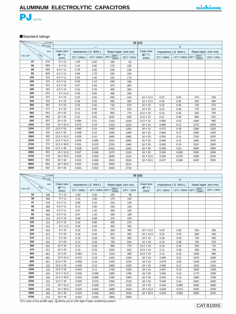
CAT.8100S
PJ series
ALUMINUM ELECTROLYTIC CAPACITORS
Standard ratings
V (Code)
Code
Case size φD × L(mm)
Case size φD × L(mm)
Impedance ( Ω MAX.) Impedance ( Ω MAX.)Rated ripple (mA rms) Rated ripple (mA rms)
16 (1C)
— 6
20˚C / 100kHz 20˚C / 100kHz–10˚C / 100kHz –10˚C / 100kHz105˚C / 120Hz 105˚C / 120HzCap. (µF)
Item
Size code
47
56
68
82
100
120
150
180
220
270
330
390
470
560
680
820
1000
1200
1500
1800
2200
2700
3300
3900
4700
5600
6800
8200
470
560
680
820
101
121
151
181
221
271
331
391
471
561
681
821
102
122
152
182
222
272
332
392
472
562
682
822
5 × 11
5 × 11
6.3 × 11
6.3 × 11
6.3 × 11
6.3 × 11
6.3 × 15
6.3 × 15
8 × 11.5
8 × 15
8 × 15
8 × 20
8 × 20
10 × 20
10 × 20
10 × 25
10 × 31.5
12.5 × 20
12.5 × 25
12.5 × 31.5
12.5 × 31.5
12.5 × 35.5
12.5 × 40
16 × 31.5
16 × 35.5
16 × 40
18 × 35.5
18 × 40
1.30
1.10
0.78
0.66
0.55
0.45
0.37
0.31
0.26
0.22
0.18
0.16
0.14
0.12
0.10
0.084
0.072
0.060
0.048
0.039
0.034
0.031
0.028
0.027
0.025
0.024
0.022
0.021
3.30
2.80
2.00
1.70
1.40
1.10
0.93
0.78
0.65
0.55
0.45
0.40
0.35
0.30
0.25
0.21
0.18
0.15
0.12
0.10
0.085
0.078
0.070
0.068
0.063
0.060
0.055
0.053
155
175
220
240
265
290
375
405
460
550
595
730
770
950
1020
1220
1410
1430
1660
1880
2010
2220
2410
2470
2680
2820
2900
3040
92
105
135
155
175
195
260
285
335
410
455
570
615
770
845
1030
1210
1250
1490
1690
1800
1990
2160
2220
2410
2530
2610
2730
10 × 12.5
10 × 12.5
10 × 15
10 × 15
12.5 × 15
12.5 × 15
12.5 × 15
16 × 15
16 × 15
18 × 15
16 × 20
16 × 20
16 × 25
18 × 20
18 × 25
18 × 31.5
18 × 35.5
0.22
0.18
0.16
0.14
0.13
0.11
0.096
0.084
0.072
0.066
0.054
0.048
0.040
0.039
0.034
0.028
0.027
0.55
0.45
0.40
0.35
0.33
0.28
0.24
0.21
0.18
0.17
0.14
0.12
0.10
0.10
0.085
0.070
0.068
575
625
730
770
920
985
1060
1270
1390
1560
1700
1800
2010
2090
2290
2490
2620
430
480
570
615
745
815
895
1090
1220
1400
1530
1620
1800
1880
2060
2240
2350
105˚C / 10kHz ~200kHz 105˚C /10kHz ~
200kHz
V (Code)
Code
Case size φD × L(mm)
Case size φD × L(mm)
Impedance ( Ω MAX.) Impedance ( Ω MAX.)Rated ripple (mA rms) Rated ripple (mA rms)
25 (1E)
— 6
20˚C / 100kHz 20˚C / 100kHz–10˚C / 100kHz –10˚C / 100kHz105˚C / 105˚C / 120Hz 105˚C / 120HzCap. (µF)
Item
Size code
10kHz ~200kHz 105˚C / 10kHz ~
200kHz 33
39
47
56
68
82
100
120
150
180
220
270
330
390
470
560
680
820
1000
1200
1500
1800
2200
2700
3300
3900
4700
330
390
470
560
680
820
101
121
151
181
221
271
331
391
471
561
681
821
102
122
152
182
222
272
332
392
472
5 × 11
5 × 11
6.3 × 11
6.3 × 11
6.3 × 11
6.3 × 11
6.3 × 15
6.3 × 15
8 × 11.5
8 × 15
8 × 15
8 × 20
8 × 20
10 × 20
10 × 20
10 × 25
10 × 31.5
12.5 × 20
12.5 × 25
12.5 × 25
12.5 × 31.5
12.5 × 35.5
12.5 × 40
16 × 31.5
16 × 35.5
16 × 40
18 × 40
1.30
1.10
0.84
0.72
0.57
0.47
0.39
0.32
0.26
0.22
0.18
0.15
0.13
0.11
0.10
0.084
0.072
0.059
0.048
0.043
0.035
0.032
0.029
0.027
0.025
0.023
0.022
3.30
2.80
2.10
1.80
1.40
1.20
0.98
0.80
0.65
0.55
0.45
0.38
0.33
0.28
0.25
0.21
0.18
0.15
0.12
0.11
0.088
0.080
0.073
0.068
0.063
0.058
0.055
155
175
210
235
260
285
370
405
460
550
625
750
795
985
1020
1220
1420
1430
1660
1760
1980
2180
2360
2470
2680
2820
2960
88
100
125
140
160
180
245
275
320
390
455
560
610
770
810
990
1180
1210
1430
1550
1780
1960
2120
2220
2410
2530
2660
10 × 12.5
10 × 12.5
10 × 15
10 × 15
12.5 × 15
12.5 × 15
12.5 × 15
16 × 15
16 × 15
18 × 15
18 × 15
16 × 20
16 × 25
18 × 20
18 × 25
18 × 31.5
18 × 35.5
0.24
0.21
0.18
0.15
0.13
0.11
0.10
0.084
0.079
0.066
0.061
0.050
0.041
0.040
0.034
0.029
0.026
0.60
0.53
0.45
0.38
0.33
0.28
0.25
0.21
0.20
0.17
0.15
0.13
0.10
0.10
0.085
0.073
0.065
555
600
700
750
920
985
1060
1270
1340
1520
1600
1770
1980
2050
2290
2490
2690
395
435
525
575
720
785
860
1050
1130
1310
1400
1590
1780
1840
2060
2240
2420
In case of low profile type, will be put at 12th digit of type numbering system. 6

CAT.8100S
PJ series
ALUMINUM ELECTROLYTIC CAPACITORS
Standard ratingsV (Code)
Code
Case size φD × L(mm)
Case size φD × L(mm)
Impedance ( Ω MAX.) Impedance ( Ω MAX.)Rated ripple (mA rms) Rated ripple (mA rms)
35 (1V)— 6
20˚C / 100kHz 20˚C / 100kHz–10˚C / 100kHz –10˚C / 100kHz105˚C / 120Hz 105˚C / 120HzCap. (µF)
Size code
22
27
33
39
47
56
68
82
100
120
150
180
220
270
330
390
470
560
680
820
1000
1200
1500
1800
2200
2700
3300
220
270
330
390
470
560
680
820
101
121
151
181
221
271
331
391
471
561
681
821
102
122
152
182
222
272
332
5 × 11
5 × 11
6.3 × 11
6.3 × 11
6.3 × 11
6.3 × 11
6.3 × 15
6.3 × 15
8 × 11.5
8 × 15
8 × 15
8 × 20
8 × 20
10 × 20
10 × 20
10 × 25
10 × 31.5
12.5 × 20
12.5 × 25
12.5 × 25
12.5 × 31.5
12.5 × 35.5
12.5 × 40
16 × 31.5
16 × 35.5
16 × 40
18 × 40
1.30
1.00
0.78
0.66
0.54
0.45
0.37
0.31
0.26
0.22
0.18
0.16
0.13
0.11
0.096
0.084
0.072
0.059
0.048
0.042
0.035
0.031
0.029
0.027
0.024
0.022
0.021
3.30
2.50
2.00
1.70
1.40
1.10
0.93
0.78
0.65
0.55
0.45
0.40
0.33
0.28
0.24
0.21
0.18
0.15
0.12
0.11
0.088
0.078
0.073
0.068
0.060
0.055
0.053
160
180
225
245
270
295
370
415
460
550
595
730
795
985
1060
1220
1420
1430
1660
1760
1980
2180
2360
2470
2680
2900
3040
85
99
125
140
160
180
230
265
305
370
415
520
580
735
810
955
1130
1160
1370
1490
1710
1920
2120
2220
2410
2610
2730
10 × 12.5
10 × 12.5
10 × 15
10 × 15
12.5 × 15
12.5 × 15
12.5 × 15
16 × 15
16 × 15
18 × 15
18 × 15
16 × 20
16 × 25
18 × 20
18 × 25
18 × 31.5
18 × 35.5
0.24
0.20
0.18
0.14
0.13
0.10
0.096
0.084
0.075
0.066
0.060
0.050
0.041
0.040
0.034
0.028
0.026
0.60
0.50
0.45
0.35
0.33
0.25
0.24
0.21
0.19
0.17
0.15
0.13
0.10
0.10
0.085
0.070
0.065
555
625
700
770
920
1020
1060
1270
1360
1540
1620
1770
1980
2050
2290
2490
2690
375
435
500
560
690
780
825
1010
1100
1270
1370
1530
1740
1840
2060
2240
2420
105˚C /10kHz ~200kHz 105˚C /10kHz ~
200kHz
V (Code)
Code
Case size φD × L(mm)
Case size φD × L(mm)
Impedance ( Ω MAX.) Impedance ( Ω MAX.)Rated ripple (mA rms) Rated ripple (mA rms)
50 (1H)— 6
20˚C / 100kHz 20˚C / 100kHz–10˚C / 100kHz –10˚C / 100kHz105˚C / 120Hz 105˚C / 120HzCap. (µF)
Size code
R47R680101R52R23R34R76R8100120150180220270330390470560680820101121151181221271331391471561681821102122152182222
5 × 115 × 115 × 115 × 115 × 115 × 115 × 115 × 115 × 115 × 115 × 115 × 11
6.3 × 116.3 × 116.3 × 116.3 × 116.3 × 156.3 × 15
8 × 11.58 × 158 × 208 × 20
10 × 2010 × 2010 × 2510 × 31.510 × 31.5
12.5 × 2512.5 × 2512.5 × 31.512.5 × 35.512.5 × 40
16 × 31.516 × 35.516 × 4018 × 35.518 × 40
31.0021.0014.00
9.806.504.603.102.502.001.701.301.100.910.740.600.500.420.350.280.220.180.160.130.110.0980.0850.0720.0530.0480.0400.0360.0330.0300.0280.0260.0250.024
80.0055.0038.0028.0018.0012.00
7.806.305.004.303.302.802.301.901.501.301.100.880.700.550.450.400.330.280.250.210.180.130.120.100.0900.0830.0750.0700.0650.0630.060
2228364554668191
115125145155195215240260330360410500620670820890
1040120013001440150016801850201021202260241024602560
111418222733404557627279
100115135150195220255320410455570635760900995
1120119013601530170018301990217022102300
10 × 12.510 × 1510 × 15
12.5 × 1512.5 × 1512.5 × 15
16 × 1516 × 1516 × 1518 × 1516 × 2016 × 2018 × 2018 × 2518 × 31.518 × 31.5
0.230.210.170.140.120.100.0910.0780.0720.0600.0530.0480.0430.0360.0310.029
0.580.530.430.350.310.250.230.200.180.150.130.120.110.0900.0780.073
510580640785845920
1120121012701470155016301810200021402220
330385435545605670840925990
1170126013501530173018801990
0.470.6811.52.23.34.76.8
101215182227333947566882
100120150180220270330390470560680820
10001200150018002200
105˚C / 10kHz ~200kHz 105˚C / 10kHz ~
200kHz
In case of low profile type, will be put at 12th digit of type numbering system. 6
Item
Item

CAT.8100S
PJ series
ALUMINUM ELECTROLYTIC CAPACITORS
Standard ratings
Code
Case size φD × L(mm)
Case size φD × L(mm)
Impedance ( Ω MAX.) Impedance ( Ω MAX.)Rated ripple (mA rms) Rated ripple (mA rms)
63 (1J)— 6
20˚C / 100kHz 20˚C / 100kHz–10˚C / 100kHz –10˚C / 100kHz105˚C / 120Hz 105˚C / 120HzCap. (µF)
Item
Size code
10
12
15
18
22
27
33
39
47
56
68
82
100
120
150
180
220
270
330
390
470
560
680
820
1000
1200
100
120
150
180
220
270
330
390
470
560
680
820
101
121
151
181
221
271
331
391
471
561
681
821
102
122
5 × 11
5 × 11
6.3 × 11
6.3 × 11
6.3 × 11
6.3 × 11
6.3 × 15
6.3 × 15
8 × 11.5
8 × 15
8 × 15
8 × 20
10 × 20
10 × 20
10 × 25
10 × 31.5
12.5 × 20
12.5 × 25
12.5 × 25
12.5 × 31.5
12.5 × 35.5
12.5 × 40
16 × 31.5
16 × 35.5
16 × 40
18 × 40
1.60
1.40
1.10
0.95
0.78
0.64
0.52
0.45
0.37
0.31
0.26
0.22
0.18
0.15
0.13
0.11
0.094
0.081
0.072
0.059
0.052
0.047
0.043
0.040
0.037
0.034
4.00
3.50
2.80
2.40
2.00
1.60
1.30
1.10
0.93
0.78
0.65
0.55
0.45
0.38
0.33
0.28
0.24
0.20
0.18
0.15
0.13
0.12
0.11
0.10
0.093
0.085
135
145
185
195
215
240
305
330
365
450
500
600
750
820
950
1110
1140
1340
1420
1620
1780
1950
2050
2220
2370
2510
67
72
92
100
110
130
170
190
215
275
315
385
495
555
665
790
835
1000
1090
1260
1420
1580
1700
1880
2050
2210
10 × 12.5
10 × 12.5
10 × 15
12.5 × 15
12.5 × 15
12.5 × 15
16 × 15
16 × 15
18 × 15
18 × 15
16 × 20
16 × 25
18 × 20
18 × 25
18 × 31.5
18 × 35.5
0.34
0.28
0.24
0.20
0.18
0.14
0.12
0.10
0.088
0.078
0.070
0.063
0.058
0.051
0.043
0.040
0.85
0.70
0.60
0.50
0.45
0.35
0.30
0.25
0.22
0.20
0.18
0.16
0.15
0.13
0.12
0.10
450
495
580
695
750
845
1050
1120
1290
1410
1500
1700
1730
1940
2110
2280
275
310
375
460
510
590
750
820
965
1080
1170
1350
1400
1610
1780
1970
105˚C /10kHz ~200kHz 105˚C / 10kHz ~
200kHz
V (Code)
Code
Case size φD × L(mm)
Case size φD × L(mm)
Impedance ( Ω MAX.) Impedance ( Ω MAX.)Rated ripple (mA rms) Rated ripple (mA rms)
80 (1K)— 6
20˚C / 100kHz 20˚C / 100kHz–10˚C / 100kHz –10˚C / 100kHz105˚C / 120Hz 105˚C / 120HzCap. (µF)
Item
Size code
4.7
6.8
10
12
15
18
22
27
33
39
47
56
68
82
100
120
150
180
220
270
330
390
470
560
680
820
1000
4R7
6R8
100
120
150
180
220
270
330
390
470
560
680
820
101
121
151
181
221
271
331
391
471
561
681
821
102
5 × 11
5 × 11
6.3 × 11
6.3 × 11
6.3 × 11
6.3 × 11
6.3 × 15
6.3 × 15
8 × 11.5
8 × 15
8 × 15
8 × 20
10 × 20
10 × 20
10 × 25
10 × 31.5
10 × 31.5
12.5 × 25
12.5 × 31.5
12.5 × 31.5
12.5 × 35.5
12.5 × 40
16 × 31.5
16 × 35.5
16 × 40
18 × 35.5
18 × 40
4.20
2.60
1.70
1.40
1.20
1.00
0.77
0.63
0.53
0.46
0.39
0.34
0.28
0.25
0.21
0.18
0.15
0.13
0.12
0.10
0.088
0.078
0.069
0.062
0.055
0.049
0.044
11.00
7.00
4.60
3.80
3.20
2.70
2.10
1.70
1.40
1.20
1.10
0.92
0.76
0.68
0.57
0.49
0.41
0.35
0.32
0.27
0.24
0.21
0.19
0.17
0.15
0.13
0.12
53
68
87
96
104
114
135
149
234
272
295
347
426
447
526
606
663
734
816
894
1000
1060
1450
1600
1770
1890
2080
26
34
43
48
52
58
71
80
132
156
175
208
264
284
347
406
459
520
595
667
767
822
1150
1300
1470
1590
1790
10 × 12.5
10 × 12.5
10 × 15
12.5 × 15
12.5 × 15
12.5 × 15
16 × 15
16 × 15
16 × 15
18 × 15
16 × 20
16 × 25
18 × 20
18 × 25
18 × 31.5
18 × 31.5
0.49
0.42
0.36
0.31
0.27
0.23
0.20
0.18
0.15
0.13
0.11
0.099
0.089
0.080
0.072
0.065
1.30
1.10
0.97
0.84
0.73
0.62
0.54
0.47
0.41
0.35
0.30
0.27
0.24
0.22
0.19
0.18
271
293
337
402
430
466
663
699
766
881
995
1140
1170
1330
1490
1560
155
174
202
249
273
308
444
484
543
643
742
874
908
1060
1210
1300
105˚C /10kHz ~200kHz 105˚C / 10kHz ~
200kHz
In case of low profile type, will be put at 12th digit of type numbering system. 6
V (Code)

CAT.8100S
PJ series
ALUMINUM ELECTROLYTIC CAPACITORS
Standard ratings
Code
Case size φD × L(mm)
Case size φD × L(mm)
Impedance ( Ω MAX.) Impedance ( Ω MAX.)Rated ripple (mA rms) Rated ripple (mA rms)
100 (2A)— 6
20˚C / 100kHz 20˚C / 100kHz–10˚C / 100kHz –10˚C / 100kHz105˚C / 120Hz 105˚C / 120HzCap. (µF)
Size code
0.47
0.68
1
1.5
2.2
3.3
4.7
6.8
10
12
15
18
22
27
33
39
47
56
68
82
100
120
150
180
220
270
330
390
470
560
680
R47
R68
010
1R5
2R2
3R3
4R7
6R8
100
120
150
180
220
270
330
390
470
560
680
820
101
121
151
181
221
271
331
391
471
561
681
5 × 11
5 × 11
5 × 11
5 × 11
5 × 11
5 × 11
6.3 × 11
6.3 × 11
6.3 × 11
6.3 × 11
6.3 × 15
6.3 × 15
8 × 11.5
8 × 15
8 × 15
8 × 20
10 × 20
10 × 20
10 × 25
10 × 31.5
10 × 31.5
12.5 × 25
12.5 × 25
12.5 × 31.5
12.5 × 35.5
12.5 × 40
16 × 31.5
16 × 35.5
16 × 40
18 × 35.5
18 × 40
43.0
23.0
17.0
10.0
6.60
4.10
2.80
1.90
1.20
1.00
0.81
0.67
0.55
0.47
0.38
0.33
0.28
0.24
0.21
0.18
0.15
0.13
0.11
0.098
0.087
0.072
0.062
0.053
0.047
0.041
0.036
116.0
62.0
46.0
27.0
18.0
11.0
7.60
5.10
3.20
2.70
2.20
1.80
1.50
1.30
1.00
0.89
0.76
0.65
0.57
0.49
0.41
0.35
0.30
0.26
0.23
0.19
0.17
0.14
0.13
0.11
0.097
17
23
27
35
43
54
68
83
104
114
131
155
230
269
299
352
423
456
526
606
663
774
798
904
1000
1130
1520
1730
1920
2070
2300
8
11
13
17
21
27
34
41
52
57
65
73
122
146
169
202
252
274
326
386
438
519
553
641
730
843
1160
1340
1530
1680
1910
10 × 12.5
10 × 12.5
10 × 15
12.5 × 15
12.5 × 15
12.5 × 15
16 × 15
16 × 15
16 × 15
18 × 15
16 × 20
16 × 25
18 × 20
18 × 25
18 × 31.5
18 × 35.5
0.50
0.42
0.36
0.31
0.27
0.23
0.19
0.17
0.14
0.12
0.11
0.093
0.080
0.070
0.062
0.056
1.40
1.10
0.97
0.84
0.73
0.62
0.51
0.46
0.38
0.32
0.30
0.25
0.22
0.19
0.17
0.15
268
293
337
402
430
466
681
719
793
917
995
1170
1230
1420
1600
1770
145
166
193
239
258
289
433
475
531
635
706
854
918
1080
1240
1410
105˚C /10kHz ~200kHz 105˚C /10kHz ~
200kHz
1
2.2
3.3
4.7
10
22
33
47
100
010
2R2
3R3
4R7
100
220
330
470
101
8 × 11.5
8 × 11.5
10 × 12.5
10 × 12.5
10 × 15
12.5 × 20
12.5 × 25
16 × 25
16 × 35.5
19
30
50
57
90
140
175
220
330
2CCap. (µF)
Rated Ripple (mA rms) at 105˚C 120Hz
160
2D
200
2E
250
2F
315
2V
350
2G
400
2W
450
8 × 11.5
8 × 11.5
10 × 12.5
10 × 15
10 × 20
12.5 × 25
16 × 25
16 × 25
18 × 40
19
30
50
60
95
145
180
220
345
10 × 15
10 × 20
12.5 × 20
12.5 × 25
16 × 25
16 × 35.5
18 × 40
Case size
17
28
48
55
90
135
170
8 × 11.5
10 × 12.5
10 × 15
10 × 15
12.5 × 20
16 × 25
16 × 25
16 × 31.5
18 × 40
19
32
52
60
98
150
180
225
345
8 × 11.5
10 × 12.5
10 × 15
10 × 20
12.5 × 20
16 × 25
16 × 31.5
18 × 35.5
19
32
52
65
98
150
185
235
10 × 12.5
10 × 15
10 × 20
10 × 20
12.5 × 25
16 × 25
16 × 35.5
18 × 40
21
34
54
65
100
150
190
240
10 × 12.5
10 × 15
10 × 20
12.5 × 20
12.5 × 25
16 × 31.5
18 × 35.5
17
28
47
55
85
130
170
V (Code)
V
In case of low profile type, will be put at 12th digit of type numbering system. 6
Item
Code

CAT.8100S
Eco-Products “GeoCap”
Nichicon promotes environmentally conscious practices.
Nichicon offers “GeoCap”,which has completely lead free terminals and contains no polyvinylchloride in the sleeve.
Complied
Plastic Film Capacitors
For Electronic Equipment
For Electric Equipment
XJ, XN, XD, XF, AS, AF
YX, YS, YP, YR, YK
XU
EH, EN
Complied
Type • Classification Series Lead-Free Compliance Anti Polyvinyl Chloride Compliance
For Noise Filter
PLASTIC FILM CAPACITORS
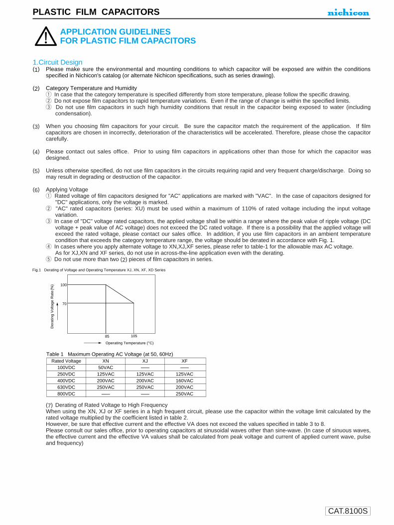
CAT.8100S
1.Circuit Design(1) Please make sure the environmental and mounting conditions to which capacitor will be exposed are within the conditions
specified in Nichicon's catalog (or alternate Nichicon specifications, such as series drawing).
(2) Category Temperature and Humidityq In case that the category temperature is specified differently from store temperature, please follow the specific drawing.w Do not expose film capacitors to rapid temperature variations. Even if the range of change is within the specified limits.e Do not use film capacitors in such high humidity conditions that result in the capacitor being exposed to water (including
condensation).
(3) When you choosing film capacitors for your circuit. Be sure the capacitor match the requirement of the application. If filmcapacitors are chosen in incorrectly, deterioration of the characteristics will be accelerated. Therefore, please chose the capacitorcarefully.
(4) Please contact out sales office. Prior to using film capacitors in applications other than those for which the capacitor wasdesigned.
(5) Unless otherwise specified, do not use film capacitors in the circuits requiring rapid and very frequent charge/discharge. Doing somay result in degrading or destruction of the capacitor.
(6) Applying Voltageq Rated voltage of film capacitors designed for "AC" applications are marked with "VAC". In the case of capacitors designed for
"DC" applications, only the voltage is marked.w "AC" rated capacitors (series: XU) must be used within a maximum of 110% of rated voltage including the input voltage
variation.e In case of "DC" voltage rated capacitors, the applied voltage shall be within a range where the peak value of ripple voltage (DC
voltage + peak value of AC voltage) does not exceed the DC rated voltage. If there is a possibility that the applied voltage willexceed the rated voltage, please contact our sales office. In addition, if you use film capacitors in an ambient temperaturecondition that exceeds the category temperature range, the voltage should be derated in accordance with Fig. 1.
r In cases where you apply alternate voltage to XN,XJ,XF series, please refer to table-1 for the allowable max AC voltage.As for XJ,XN and XF series, do not use in across-the-line application even with the derating.
t Do not use more than two (2) pieces of film capacitors in series.
(7) Derating of Rated Voltage to High FrequencyWhen using the XN, XJ or XF series in a high frequent circuit, please use the capacitor within the voltage limit calculated by therated voltage multiplied by the coefficient listed in table 2.However, be sure that effective current and the effective VA does not exceed the values specified in table 3 to 8.Please consult our sales office, prior to operating capacitors at sinusoidal waves other than sine-wave. (In case of sinuous waves,the effective current and the effective VA values shall be calculated from peak voltage and current of applied current wave, pulseand frequency)
APPLICATION GUIDELINESFOR PLASTIC FILM CAPACITORS
Fig.1 Derating of Voltage and Operating Temperature XJ, XN, XF, XD Series
Der
atin
g V
olta
ge R
ate
(%)
Operating Temperature (°C)
85 105
100
70
Table 1 Maximum Operating AC Voltage (at 50, 60Hz)Rated Voltage XN XJ XF
100VDC 50VAC -------- --------250VDC 125VAC 125VAC 125VAC400VDC 200VAC 200VAC 160VAC630VDC 250VAC 250VAC 200VAC800VDC -------- -------- 250VAC
PLASTIC FILM CAPACITORS

(8) Permissible Current, VA value and Inherent Temperature Riseq Do not use film capacitors in circuits that may exceed the maximum permissible current as specified in tables 3 to 8. The
permissible current will values will vary due to material and design, even though appearance is similar, therefore, pleasecarefully confirm all perimeters using the specification.Also, if the capacitors to be subjected to a sinuous wave flow, please contact our sales office to select the proper capacitor.
w The permissible VA value is restricted by the upper category temperature(ambient temperature + inherent temperature +radiant heat).Do not use the capacitor in circuits which exceed the maximum permissible VA value specified in table 3 to 8. The permissiblevalues will vary due to material and design, even though appearance is similar, therefore, please carefully confirm allperimeters using the specification.Also, if the capacitors to be subjected to a sinuous wave flow, please contact our sales office to select the proper capacitor.
e The inherent temperature under a no air flow shall be within the value listed below.XJ, XN series..+10°C or belowXF, XD series..+5°C or below
(9) A "hum" may be produced under certain high frequency wave conditions. The "hum" does not effect the capacitor characteristics.Please consult our sales office if your application does not permit a "hum".(10) When designing circuit boards, please take into consideration how other parts would be affected should
the capacitor develop a short or open circuit.
2. Mounting(1) Installation
q When installing capacitors, you must avoid any pulling, pushing or twisting stress to the leads or terminals.w Certain coditions, such as large capacitor body size or serious vibration, require the capacitor body to be affixed to the board
using holders or resin coating. When using such materials, please be sure they do not effect the capacitor characteristics.(2) Soldering
q When soldering capacitors, avoid proesses that require a long dwell time or high temperatures. Such conditions will result indeterioration of characteristics or short-circuit defects. Please ensure that the soldering process is within the range shown inthe following Fig. 2.
w When using a soldering iron to solder the capacitor, the soldering condition must be within the following specifications:Bit temperature: 350 ± 10°CApplication time of soldering iron : 3 sedond
e If re-work is necessary, please wait until the capacitor temperature is equal to room temperature. Do not re-work more thantwice.
r Please do not use Infrared-reflow an it will cause serious heat stress to the capacitor.t Prior to soldering film capacitors on the same PC board as chip type capacitors, please consult our sales office to confirm the
compatibility of the soldering process.
CAT.8100S
Table 2 Derating of Voltage at High FrequencyXJ, XN Series XF Series
Frequency Derating Rate to Frequency Derating Rate to50/60Hz AC Rated voltage 50/60Hz AC Rated voltage
50/60 (Hz) 100 (%) 50/60 (Hz) 100 (%)001k 54 001k 76005k 39 005k 55010k 34 010k 49020k 30 020k 41030k 27 030k 38040k 26 040k 36050k 25 050k 35060k 24 060k 33070k 23 070k 32080k 22 080k 31090k 21 090k 30100k 21 100k 30
PLASTIC FILM CAPACITORS
Tem
p (
°C)
Fig. 2 Solder temp. and soldering time
In case soldering iron in used.In case of solder dipping.
Preheat shall be less than 1 minute at a temperature lower than 110°C
Soldering Time (Sec.)
1 2 3 4 5 6 7 8 9 10
360
340
320
300
280
260
240
220

CAT.8100S
PLASTIC FILM CAPACITORS
(3) Cleaningq If it is necessary to use cleaning agents to wash the board after soldering, please select alcohol based agents such as
isopropyl alcohol.w Please wash the board as soon as possible after soldering.e Please dry the board as soon as possible after cleaning.
3. In the equipment(1) Do not directly touch the terminal with your hand.(2) Do not short between terminals be conductor, nor spill conductible liquid such as alkaline nor acidic solution on or near the
capacitor.(3) Please make sure that the ambient conditions where the set is installed will be free from spilling water or oil, direct sunlight,
ultraviolet rays, radiation, poisonous gas, vibration or mechanical shock.
4. Maintenance and Inspection(1) If periodical inspection is required, please inspect the capacitor based on the specification of the drawings or catalog.
5. In an Emergency(1) If you see or smell smoke, immediately turn off the main switch or pull out the plug from the outlet.
6. Storage(1) Storage
q Do not store the capacitor in high temperature or high humidity. The ambient storage conditions should be:Temperature : --10°C~+40°CHumidity : lower than 75%Place : indoor
Ambient conditions to avoid;quick temperature changeExposure to spilling water or oil, direct sunlight,
ultraviolet rays, radiation, poisonous gas such as hydrogen sulfide, sulfurous acid, nitrous acid, chorine, ammonium, etc..
w Please store the capacitors in the original packed condition to avoid any physical stress to the capacitor.(2) Handling
q Do not apply excess vibration, mechanical shock (drop) or pressure to the capacitor.w Do not apply stress to the lead such as bending, pulling or twisting.
7. Disposal(1) Please dispose capacitors as industrial waste.
8. Other(1) Contents of this catalog (specifications, material, etc.) are subject to change without notice.
Technical information (data) contained in this material is for description representation and application of the product and does notconstitute any guarantee.
(2) When ordering, please include the following information:q Voltage to be applied ("DC" or "AC", ripple value)w Rated capacitance value and rated capacitance tolerancee Category temperature range (inherent temperature + radiant heat should be inclued)r Specific operating condition (wave form, effective current, dv/dt, etc.)t Estimated failure mode
If the capacitor should fail, what effect will this have on the components or set.If other components should fail, what effect will it have on the capacitor.
y Soldering condition (pre-heat condition, solder temperature, Dipping time, profile when chip parts are mounted on the sameboard)
u Set ambient condition (max. operating temperature, method of affixing, automobile use, existence of any gas surrounding capacitor)
(3) Do not use parts provided as samples in sets for resale.
The above mentioned material is according to EIAJ RCR2350 B(issued in July 2002) titled "Guideline of notabilia for Fixed PlasticFilm Capacitors for use in Electronic Equipment". Please refer tothe book for details.

CAT.8100S
PLASTIC FILM CAPACITORS
RatedCapacitance Code
(µF)
0.001 1020.0047 4720.01 1030.047 4730.1 1040.47 4741.0 1054.7 475
10 106
Item CodePlastic filmCapacitiors
Q
Capacitance Tolerance Code(%)±5 J±10 K
Rated Voltage(V) Code
50 1H100 2A125 2B250 2E400 2G630 2J800 2K
Type numbering system
Dielectric Film CodePolyester film
orTPolyester film &
Polypropylene film
Polypropylene film R
Lead CodeSoldered CP wire P
Tinned CP wire N
1 2 3 4 5 6 7 8 9 10 11 12 13 15 1614
10
11
See pages236 ~ 247
See page 225
Type Series name Rated voltage Rated Capacitance Specificationclassification
Capacitancetolerance
Configuration

CAT.8100S
PLASTIC FILM CAPACITORS
Table 3 XJ Series Permissible Current and VA Value
RatedCapacitance
(µF)
PermissibleEffective Current
le (A)
250VDC (2E)
Permissible PeakCurrent at
Single Pulse
lp2 (A)
Permissible VA Value(le×Ve)
Operating Temp.85°C(VA)
Operating Temp.65°C(VA)
PermissibleEffective Current
le (A)
Permissible PeakCurrent at
Single Pulse
lp2 (A)
Permissible VA Value(le×Ve)
Operating Temp.85°C(VA)
Operating Temp.65°C(VA)
PermissibleEffective Current
le (A)
Permissible PeakCurrent at
Single Pulse
lp2 (A)
Permissible VA Value(le×Ve)
Operating Temp.85°C(VA)
Operating Temp.65°C(VA)
400VDC (2G) 630VDC (2J)
0.01 0.1 1.0 2.6 11.2
0.015 0.15 1.5 2.9 12.5
0.022 0.2 2.0 2.3 10.2 0.25 2.5 3.2 14.2
0.033 0.25 2.5 2.6 11.4 0.3 3.0 3.8 16.6
0.047 0.3 3.0 2.2 9.8 0.3 3.0 2.9 12.6 0.3 3.0 4.3 18.6
0.068 0.35 3.5 2.2 9.8 0.45 4.5 3.3 14.3 0.45 4.5 5.0 21.8
0.1 0.4 4.0 2.5 10.9 0.45 4.5 3.8 16.4 0.6 6.0 5.6 24.6
0.15 0.5 5.0 2.9 12.6 0.6 6.0 4.5 19.6 0.7 7.0 7.2 31.4
0.22 0.85 8.5 3.3 14.3 0.8 8.0 5.1 22.5 1.0 10.0 8.4 36.9
0.33 0.9 9.0 3.8 16.6 1.3 13.0 6.1 26.9 1.5 15.0 10.1 44.3
0.47 1.0 10.0 4.5 19.8 1.5 15.0 7.2 31.4 1.6 16.0 11.0 52.7
0.68 1.5 15.0 5.3 23.0 1.8 18.0 9.0 39.4
1.0 2.25 22.5 6.1 26.9 2.5 25.0 10.6 46.6
1.5 2.4 24.0 7.9 34.8 3.0 30.0 13.0 56.8
2.2 3.5 35.0 9.4 40.9
3.3 4.0 40.0 11.5 50.2
Table 4 XF Series Permissible Current and VA Value
RatedCapacitance
(µF)
PermissibleEffectiveCurrent
le (A)
250VDC (2E)
PermissiblePeak
Current atSingle Pulse
lp2 (A)
Permissible VA Value(le×Ve)
OperatingTemp.85°C(VA)
OperatingTemp.65°C(VA)
PermissibleEffectiveCurrent
le (A)
PermissiblePeak
Current atSingle Pulse
lp2 (A)
Permissible VA Value(le×Ve)
OperatingTemp.85°C(VA)
OperatingTemp.65°C(VA)
PermissibleEffectiveCurrent
le (A)
PermissiblePeak
Current atSingle Pulse
lp2 (A)
Permissible VA Value(le×Ve)
OperatingTemp.85°C(VA)
OperatingTemp.65°C(VA)
PermissibleEffectiveCurrent
le (A)
PermissiblePeak
Current atSingle Pulse
lp2 (A)
Permissible VA Value(le×Ve)
OperatingTemp.85°C(VA)
OperatingTemp.
Max.65°C(VA)
400VDC (2G) 630VDC (2J) 800VDC (2K)
0.010 0.15 01.5 08 026 0.20 02.0 09 029
0.015 0.20 02.0 08 029 0.25 02.5 10 033
0.022 0.20 02.0 08 026 0.30 03.0 09 032 0.25 02.5 11 039
0.033 0.35 03.5 09 031 0.35 03.5 10 035 0.30 03.0 13 045
0.047 0.30 03.0 08 026 0.50 05.0 10 034 0.35 03.5 13 043 0.50 05.0 16 052
0.068 0.40 04.0 08 029 0.50 05.0 12 040 0.50 05.0 15 050 0.70 07.0 18 060
0.100 0.60 06.0 09 032 0.60 06.0 14 047 0.75 07.5 17 057 0.85 08.5 22 072
0.150 0.80 08.0 11 037 0.90 09.0 16 055 1.00 10.0 20 067 1.00 10.0 27 090
0.220 0.80 08.0 13 045 1.30 13.0 19 064 1.10 11.0 25 084 1.40 14.0 31 103
0.330 1.20 12.0 16 052 1.60 16.0 23 078 1.75 17.5 30 100 1.75 17.5 39 130
0.470 1.70 17.0 18 060 1.90 19.0 29 097 1.90 19.0 36 119 2.50 25.0 47 155
0.680 2.50 25.0 21 072 2.60 26.0 34 114 2.70 27.0 42 141
1.000 2.60 26.0 28 092 3.10 31.0 42 139
1.500 3.85 38.5 33 110 4.75 47.5 51 169
2.200 4.40 44.0 41 135
3.300 5.00 50.0 49 163
Table 5 XN Series Permissible Current and VA Value250VDC (2E) 400VDC (2G) 630VDC (2J)
0.010 00.10 01.0 01.2 05.2 0.10 01.0 01.2 05.2 0.08 00.8 01.8 07.9
0.015 00.10 01.0 01.2 05.2 0.10 01.0 01.3 05.5 0.10 01.0 02.0 08.9
0.022 00.15 01.5 01.3 05.5 0.15 01.5 01.5 06.4 0.15 01.5 02.5 10.6
0.033 00.15 01.5 01.4 05.9 0.15 01.5 01.7 07.6 0.15 01.5 02.9 12.5
0.047 00.15 01.5 01.4 05.9 0.20 02.0 02.1 09.0 0.20 02.0 03.2 14.0
0.068 00.25 02.5 01.6 06.8 0.25 02.5 02.4 10.4 0.25 02.5 03.8 16.3
0.100 00.35 03.5 01.9 08.1 0.30 03.0 02.8 12.3 0.30 03.0 04.8 21.0
0.150 00.40 04.0 02.3 09.9 0.35 03.5 04.0 17.2 0.50 05.0 06.1 26.4
0.220 00.60 06.0 02.6 11.5 0.50 05.0 04.5 19.6 0.60 06.0 06.5 28.2
0.330 00.60 06.0 03.3 14.3 0.70 07.0 05.0 21.5 0.70 07.0 07.9 34.4
0.470 00.70 07.0 04.2 18.2 0.80 08.0 06.3 27.1 0.90 09.0 09.3 40.1
0.680 01.00 10.0 05.2 22.7 0.90 09.0 07.4 31.9 1.30 13.0 11.1 48.0
1.000 01.40 14.0 06.1 26.5 1.20 12.0 08.7 37.6 1.50 15.0 12.9 55.8
1.500 01.60 16.0 06.7 29.1 1.50 15.0 10.3 44.5 2.00 20.0 15.9 69.0
2.200 01.80 18.0 08.1 35.3 2.20 22.0 12.3 53.5 3.00 30.0 19.0 82.0
3.300 02.50 25.0 09.8 42.6
4.700 03.00 30.0 11.8 51.0
6.800 03.00 30.0 13.7 59.3
10.000 03.00 30.0 16.9 73.2
RatedCapacitance
(µF)
PermissibleEffectiveCurrent
le (A)
PermissiblePeak
Current atSingle Pulse
lp2 (A)
Permissible VA Value(le×Ve)
OperatingTemp.85°C(VA)
OperatingTemp.65°C(VA)
PermissibleEffectiveCurrent
le (A)
PermissiblePeak
Current atSingle Pulse
lp2 (A)
Permissible VA Value(le×Ve)
OperatingTemp.85°C(VA)
OperatingTemp.65°C(VA)
PermissibleEffectiveCurrent
le (A)
PermissiblePeak
Current atSingle Pulse
lp2 (A)
Permissible VA Value(le×Ve)
OperatingTemp.85°C(VA)
OperatingTemp.65°C(VA)

CAT.8100S
Table 6 Example of current wave forms.
Item Wave form diagram Maximum Effective value
Sine wave
Harf-wave rectificationsine wave
Fill-wave rectificationsine wave
Rectangular wave
Rectangular pulse wave
Isosceles trangular wave
Saw tooth wave
Trapezoidal wave
lm
lm
lm
lm
lm
lm
lm
lm
lm
lm
lm
lm
lm
lm
lm
3
3T6t2—2t1
t1T
2
2
2
lm
3
lm
T
lm
T
lm
T
lm
T
lm
T
lm
T
T
lm
lm
T
t2t1
t1
PLASTIC FILM CAPACITORS
Table 7 AS Series Permissible Current and VA Value
250VDC (2E) 400VDC (2G) 630VDC (2J) Permissible VA Value (Ie×Ve) Permissible VA Value (Ie×Ve) Permissible VA Value (Ie×Ve)
(µF) Ie(A) Ip2(A) (VA) (VA) Ie(A) Ip2(A) (VA) (VA) Ie(A) Ip2(A) (VA) (VA) 0.1 0.5 5 6 260.15 0.8 8 7 330.22 1.1 11 8 380.33 1.4 14 7 30 1.7 17 10 460.47 1.1 11 4 20 1.7 17 8 35 1.8 18 12 530.68 1.6 16 5 24 1.9 19 9 38 2.1 21 14 621.0 2.3 23 7 30 2.8 28 10 46 2.5 25 17 771.5 2.5 25 8 34 3.5 35 13 59 3.5 35 22 952.2 3.0 30 9 40 3.5 35 15 68 4.0 40 25 1103.3 4.0 40 11 50 4.5 45 19 85 5.5 55 32 1384.7 4.5 45 13 59 5.0 50 22 976.8 5.0 50 16 69
10.0 5.5 55 19 85
Rated
CapacitancePermissible
Effective Current
Permissible PeakCurrent at
Single PulseOperating Temp.
85°COperating Temp.
65°C
Permissible
Effective Current
Permissible PeakCurrent at
Single Pulse
Operating Temp.85°C
Operating Temp.65°C
Permissible
Effective Current
Permissible PeakCurrent at
Single PulseOperating Tenp.
85°COperating Temp.
65°C
Table 8 AF Series Permissible Current and VA Value250VDC (2E) 400VDC (2G) 630VDC (2J)
Permissible VA Value (Ie×Ve) Permissible VA Value (Ie×Ve) Permissible VA Value (Ie×Ve)
(µF) Ie(A) Ip2(A) (VA) (VA) Ie(A) Ip2(A) (VA) (VA) Ie(A) Ip2(A) (VA) (VA) 0.15 0.8 8 21 730.22 1.2 12 26 900.33 1.4 14 24 85 1.8 18 31 1080.47 1.2 12 19 67 2.0 20 28 100 1.9 19 35 1230.68 1.8 18 23 83 2.6 26 35 124 2.7 27 42 1471.0 2.6 26 28 98 3.0 30 41 144 3.0 30 48 1701.5 3.5 35 34 118 4.0 40 52 182 4.0 40 60 2132.2 4.0 40 39 138 5.0 50 59 206 5.0 50 74 2603.3 5.0 50 50 175 5.0 50 74 260 5.5 55 87 2874.7 5.5 55 56 196 5.5 55 85 2996.8 5.5 55 69 223
10.0 5.5 55 81 284
Rated
CapacitancePermissible
Effective Current
Permissible PeakCurrent at
Sinle PulseOperating Temp.
85°COperating Temp.
65°C
Permissible
Effective Current
Permissible PeakCurrent at
Single Pulse
Operating Temp.85°C
Operating Temp.65°C
Permissible
Effective Current
Permissible PeakCurrent at
Single PulseOperating Temp.
85°COperating Temp.
65°C

CAT.8100S
PLASTIC FILM CAPACITORS
Type numbering system
Dimensions
Taping specifications
Style A (Lead pitch 5mm)
Style M (Lead pitch 5mm) Style E (Lead pitch 7.5mm) Style R (Lead pitch 7.5mm)
Style L (Lead pitch 5mm)
The order quantity must be in multiples of the base quantity.
PP2
PP2
P0
P0
P1
D0d
H1
H0
W1
W0
W2
W
C
L
B∆h∆h
A
F
P1 F
MA
X.5
MA
X.5
MAX.1
H0
r
PP2
P0
P1 F
MA
X.5
H0
PP2
P'0
P0
P1 F
MA
X.5
H0
PP2
P'0
P0
P1 F
MA
X.5
H0
Remarks ∗ : No feed hole omission is allowed.
Note 1) Measuring positions for P1, F, and H0 shall be at the lower part of lead wire clinch.2) Conseecutive omissions due to rejected components shall be allowed up to 1 piece, provided
that the first one after turn-up shall be with no taping and not be counted among the omissionnumbers.
3) When connecting tapes, both of front and back sides shall be sticked with hold-down tape.4) At the start and end of taping, empty feeding shall be corresponding to more than 8, and
less than 11 pieces.5) Marking shall be allowed at either side of components.
Representing taped unit
T : Ammo-pack
Code
Code Lead-to-lead distance (F) Pitch of component (P)
RT3141312
PTK301J2JXQ
A
L
M
E
R
5.0
5.0
5.0
7.5
7.5 30.0
12.7
15.0
25.4
15.0
Taped Capacitors for Automatic Insertion Systems
Item Symbol Dimensions (mm) A L M E R Tolerance
Pitch of component P 12.7 15.0 25.4 15.0 30.0 ± 1.0Feed hole pitch P0∗ 12.7 15.0 25.4 15.0 30.0 ± 0.3Feed hole pitch P'0∗ --- --- 12.7 --- 15.0 ± 0.3Distance between hole and lead wire P1 3.85 5.0 3.85 3.75 3.75 ± 0.7Distance between hole and component P2 6.35 7.5 6.35 7.5 7.5 ± 1.3Lead-to-lead distance F 5.0 5.0 5.0 7.5 7.5 ± 0.8Tilt of component ∆h 0 ± 2.0Tape width WHold-down tape width W0 12.5 MIN.Slip out of hole W1 9.0 ± 0.5Slip out of hold-down tape W2 3.0 MAX.Lead-wire clinch height H0 16.0 ± 0.5Length of cut lead r 2.0 MAX.Feed hole diameter D0 4.0 ± 0.2Total tape thickness t 0.7 ± 0.2Cut length of rejected component L 11.0 MAX.Upper side position H1 H0 + 5 + C
18 +1.0
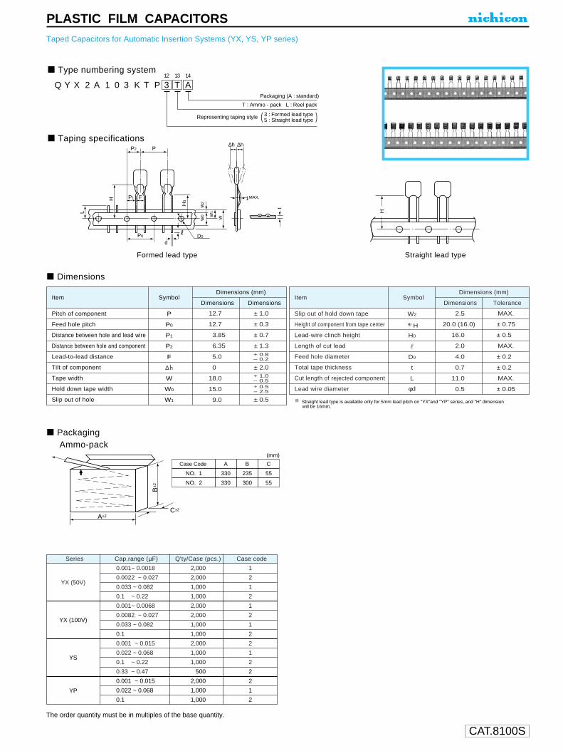
CAT.8100S
PLASTIC FILM CAPACITORSTaped Capacitors for Automatic Insertion Systems (YX, YS, YP series)
Taping specifications
Formed lead type Straight lead type
Dimensions
PackagingAmmo-pack
Q1
Y2
X3
24
A5
16
07
38
K9
T10
P11
312
T13
A14
Packaging (A : standard)
T : Ammo - pack L : Reel pack
Representing taping style 3 : Formed lead type5 : Straight lead type( )
P1
P0 D0
F
PP2
L
H
ww1
w2
w0
H0
d
∆h ∆h
1MAX.
t
H
A±2C±2
B±2
CBA
55235330NO. 1
55300330NO. 2
Case Code
(mm)
Straight lead type is available only for 5mm lead pitch on "YX"and "YP" series, and "H" dimensionwill be 16mm.
The order quantity must be in multiples of the base quantity.
ItemDimensions Dimensions
SymbolDimensions (mm)
Pitch of component
Feed hole pitch
Distance between hole and lead wire
Distance between hole and component
Lead-to-lead distance
Tilt of component
Tape width
Hold down tape width
Slip out of hole
P
P0
P1
P2
F
W
W0
W1
∆h
12.7
12.7
3.85
6.35
5.0
0
18.0
15.0
9.0
± 1.0
± 0.3
± 0.7
± 1.3
± 2.0
+ 0.8– 0.2
+ 1.0– 0.5+ 0.5– 2.5
± 0.5
ItemDimensions Tolerance
SymbolDimensions (mm)
Slip out of hold down tape
Height of component from tape center
Lead-wire clinch height
Length of cut lead
Feed hole diameter
Total tape thickness
Cut length of rejected component
Lead wire diameter
W2
H
H0
r
D0
L
φd
t
MAX.
± 0.75
± 0.5
MAX.
± 0.2
± 0.2
MAX.
± 0.05
2.5
20.0 (16.0)
16.0
2.0
4.0
0.7
11.0
0.5
Series Cap.range (µF) Case codeQ'ty/Case (pcs.)
YX (50V)
0.001~ 0.0018 2,000 1
0.0022 ~ 0.027 2,000 2
0.033 ~ 0.082 1,000 1
0.1 ~ 0.22 1,000 2
0.001~ 0.0068 2,000 1
0.0082 ~ 0.027 2,000 2
0.033 ~ 0.082 1,000 1
0.1 1,000 2
0.001 ~ 0.015 2,000 2
0.022 ~ 0.068 1,000 1
0.1 ~ 0.22 1,000 2
0.33 ~ 0.47 0,500 2
0.001 ~ 0.015 2,000 2
0.022 ~ 0.068 1,000 1
0.1 1,000 2
YX (100V)
YS
YP
Type numbering system

Pressurerelief vent
U1
P2
M3
14
E5
46
77
18
M9
H10
D11 12
Configuration
Case size code
Capacitance tolerance (± 20%)
Rated Capacitance (470µF)
Rated voltage (25V)
Series name
Type
Type
15000
10000
6800
4700
3300
2200
1500
1000
680
470
330
220
150
100
68
47
33
22
15
10
0.68
0.47
0 0.5 0.6 0.7 0.8 0.9 1.0Frequency coefficient
Cap
.(µF
)
300Hz 1kHz120Hz
Frequency coefficientRated voltage
6.3~100V
(10kHz~200kHz=1)
Small DiaLow Profile
Code
6
15MIN 4MIN
φd
P±0
.5
(φ6.3up)
φD+
0.5
MA
X
L+ MAX
In case L > 25 for the φ12.5 dia. unit, lead dia. φ d = 0.8mm.
Sleeve (P.E.T.)
φ D
5
Pb free lead finishingPb free PET sleeve
Sn-Pb lead finishingPVC sleeve contain Pb
DD DH
6.3 ED EH
8 · 10 PD PH
12.5 ~ 18 HD HH
Configuration
Please contact to us if other configurations are required.
15000
10000
6800
4700
3300
2200
1500
1000
680
470
330
220
150
100
68
47
33
22
15
10
0.68
0.47
0 0.5 0.6 0.7 0.8 0.9 1.0Frequency coefficient
Cap
.(µF
)
300Hz 1kHz120Hz
Frequency coefficientRated voltage
6.3~100V
(10kHz~200kHz=1)
160~450V50Hz 120Hz 100Hz 11kHz 110kHz~
0.80 1.00 1.25 1.40 1.60
ALUMINUM ELECTROLYTIC CAPACITORSExtremely Low Impedance, High Reliability
High reliability withstanding 5000hour load life at +105°C (3000/2000hoursfor smaller case sizes as specified below).Capacitance ranges available based on the numerical values in E12 seriesunder JIS.
Specifications
Category Temperature RangeRated Voltage RangeRated Capacitance RangeCapacitance Tolerance
Leakage Current
tan δ
Stability at Low Temperature
Endurance
Marking
Performance CharacteristicsItem
– 55 ~ +105°C (6.3 ~ 100V), –40 ~ +105°C (160 ~ 400V), –25 ~ +105°C (450V)6.3 ~ 450V0.47 ~ 15000µF±20% at 120Hz, 20°CRated Voltage (V)
Leakage current
For capacitance of more than 1000µF, add 0.02 for every increase of 1000µF. Measurement frequency : 120Hz, Temperature : 20°C
120Hz
After 1 minute's application of rated voltage, leakage current is not more
than 0.03CV or 4 (µA), whichever is greater.
Printed with white color letter on dark brown sleeve.
After an application of D.C. bias voltage plus the rated ripplecurrent for 5000 hours (2000 hours for D = 5 and 6.3,3000 hours for D=8) at 105°C the peak voltage shall notexceed the rated D.C. voltage, capacitors meet thecharacteristic requirements listed at right.
Shelf LifeAfter leaving capacitors under no load at 105°Cfor 1000 hours, they meet the characteristicrequirements listed at right.
160 ~ 450CV <= 1000 : I = 0.1CV+40 (µA) max. (1 minute's)
CV > 1000 : I = 0.04CV+100 (µA) max. (1 minute's)
Rated voltage (V)
Impedance
ratio
Z–55°C / Z+20°C
Z–40°C / Z+20°C
Z–25°C / Z+20°C
Rated Voltage (V)tan δ (MAX.)
6.30.22
6.3 · 104——
163——
25 · 353——
50~1002——
160~200—4—
250—6—
315~350—8—
400—10—
450——15
100.19
160.16
250.14
350.12
500.10
63 ~ 1000.08
160 ~ 3500.20
400 · 4500.25
Radial Lead Type
6.3 ~ 100
Type numbering system (Example : 25V 470µF)
(φD < 10) 1.5(φD >= 10) 2.0
φD
P
φd
5
2.0
0.5
6.3
2.5
0.5
8
3.5
0.6
10
5.0 5.0
0.6
12.5
0.6
16
7.5
0.8
18
7.5
0.8Frequency coefficient ofrated ripple current
Leakage current
tan δCapacitance change
Initial specified value or less200% or less of initial specified valueWithin ±20% of initial value
Leakage current
tan δCapacitance change
Initial specified value or less150% or less of initial specified valueWithin ±20% of initial value
Please refer to page 19, 20, 21 about the formed or taped product spec.Please refer to page 3 for the minimum order quantity.
PM series
(through 100V only)
PM
PW
Smaller
Dimension table in next page.
CAT.8100S

CAT.8100S
ALUMINUM ELECTROLYTIC CAPACITORS
2227333947566882
100120150180220270330390470560680820
100012001500180022002700330039004700560068008200
100001200015000
220270330390470560680820101121151181221271331391471561681821102122152182222272332392472562682822103123153
6.3 (0J) 35 (1V)
5 × 115 × 11
6.3 × 116.3 × 116.3 × 116.3 × 156.3 × 15
8 × 11.58 × 158 × 158 × 208 × 20
10 × 2010 × 2010 × 2510 × 31.510 × 31.5
12.5 × 2512.5 × 2512.5 × 31.512.5 × 35.512.5 × 40
16 × 31.516 × 35.516 × 4018 × 35.518 × 40
10 × 12.510 × 12.510 × 1510 × 15
12.5 × 1512.5 × 1512.5 × 15
16 × 1516 × 1518 × 1518 × 1516 × 2016 × 2518 × 2018 × 2518 × 31.518 × 35.5
D × L (mm)
5 × 115 × 11
6.3 × 116.3 × 116.3 × 116.3 × 116.3 × 156.3 × 15
8 × 11.58 × 158 × 158 × 208 × 20
10 × 2010 × 2010 × 2510 × 31.5
12.5 × 2012.5 × 2512.5 × 2512.5 × 31.512.5 × 35.512.5 × 40
16 × 31.516 × 35.516 × 4018 × 40
10 × 12.510 × 12.510 × 1510 × 15
12.5 × 1512.5 × 1512.5 × 15
16 × 1516 × 1518 × 1518 × 1516 × 2016 × 2518 × 2018 × 2518 × 31.518 × 35.5
25 (1E)
10 × 12.510 × 12.510 × 1510 × 15
12.5 × 1512.5 × 1512.5 × 15
16 × 1516 × 1518 × 1516 × 2016 × 2016 × 2518 × 2018 × 2518 × 31.518 × 35.5
16 (1C)
10 × 12.510 × 12.510 × 1510 × 15
12.5 × 1512.5 × 1512.5 × 15
16 × 1516 × 1518 × 1516 × 2016 × 2018 × 2018 × 2518 × 2518 × 31.518 × 35.5
5 × 115 × 11
6.3 × 116.3 × 116.3 × 116.3 × 116.3 × 156.3 × 15
8 × 11.58 × 158 × 158 × 208 × 20
10 × 2010 × 2010 × 2510 × 31.5
12.5 × 2012.5 × 2512.5 × 31.512.5 × 31.512.5 × 35.512.5 × 40
16 × 31.516 × 35.516 × 4018 × 35.518 × 40
— 6 — 6 — 6 — 6 — 610 (1A)
10 × 12.510 × 12.510 × 1510 × 15
12.5 × 1512.5 × 1512.5 × 15
16 × 1516 × 1518 × 1518 × 1516 × 2018 × 2018 × 2018 × 2518 × 31.518 × 31.5
5 × 115 × 11
6.3 × 116.3 × 116.3 × 116.3 × 116.3 × 156.3 × 15
8 × 11.58 × 158 × 158 × 208 × 20
10 × 2010 × 2010 × 2510 × 31.5
12.5 × 2012.5 × 2512.5 × 31.512.5 × 35.512.5 × 40
16 × 31.516 × 35.516 × 35.516 × 4018 × 40
5 × 115 × 11
6.3 × 116.3 × 116.3 × 116.3 × 116.3 × 156.3 × 15
8 × 11.58 × 158 × 158 × 208 × 20
10 × 2010 × 2010 × 2510 × 31.5
12.5 × 2012.5 × 2512.5 × 2512.5 × 31.512.5 × 35.512.5 × 40
16 × 31.516 × 35.516 × 4018 × 40
0.470.6811.52.23.34.76.8
101215182227333947566882
100120150180220270330390470560680820
10001200150018002200
R47R680101R52R23R34R76R8100120150180220270330390470560680820101121151181221271331391471561681821102122152182222
50 (1H)
5 × 115 × 115 × 115 × 115 × 115 × 115 × 115 × 115 × 115 × 115 × 115 × 11
6.3 × 116.3 × 116.3 × 116.3 × 116.3 × 156.3 × 15
8 × 11.58 × 158 × 208 × 20
10 × 2010 × 2010 × 2510 × 31.510 × 31.5
12.5 × 2512.5 × 2512.5 × 31.512.5 × 35.512.5 × 40
16 × 31.516 × 35.516 × 4018 × 35.518 × 40
5 × 115 × 115 × 115 × 115 × 115 × 11
6.3 × 116.3 × 116.3 × 116.3 × 116.3 × 156.3 × 15
8 × 11.58 × 158 × 158 × 20
10 × 2010 × 2010 × 2510 × 31.510 × 31.5
12.5 × 2512.5 × 2512.5 × 31.512.5 × 35.512.5 × 40
16 × 31.516 × 35.516 × 4018 × 35.518 × 40
10 × 12.510 × 12.510 × 15
12.5 × 1512.5 × 1512.5 × 15
16 × 1516 × 1516 × 1518 × 1516 × 2016 × 2518 × 2018 × 2518 × 31.518 × 35.5
100 (2A)
10 × 12.510 × 12.510 × 15
12.5 × 1512.5 × 1512.5 × 15
16 × 1516 × 1516 × 1518 × 1516 × 2016 × 2518 × 2018 × 2518 × 31.518 × 31.5
80 (1K)
10 × 12.510 × 12.510 × 15
12.5 × 1512.5 × 1512.5 × 15
16 × 1516 × 1518 × 1518 × 1516 × 2016 × 2518 × 2018 × 2518 × 31.518 × 35.5
5 × 115 × 11
6.3 × 116.3 × 116.3 × 116.3 × 116.3 × 156.3 × 15
8 × 11.58 × 158 × 158 × 20
10 × 2010 × 2010 × 2510 × 31.510 × 31.5
12.5 × 2512.5 × 31.512.5 × 31.512.5 × 35.512.5 × 40
16 × 31.516 × 35.516 × 4018 × 35.518 × 40
— 6 — 6 — 6 — 663 (1J)
10 × 12.510 × 1510 × 15
12.5 × 1512.5 × 1512.5 × 15
16 × 1516 × 1516 × 1518 × 1516 × 2016 × 2018 × 2018 × 2518 × 31.518 × 31.5
5 × 115 × 11
6.3 × 116.3 × 116.3 × 116.3 × 116.3 × 156.3 × 15
8 × 11.58 × 158 × 158 × 20
10 × 2010 × 2010 × 2510 × 31.5
12.5 × 2012.5 × 2512.5 × 2512.5 × 31.512.5 × 35.512.5 × 40
16 × 31.516 × 35.516 × 4018 × 40
Dimensions
In case of low profile type, 6 will be put at 12th digit of type numbering system.
Cap.(µF) Code
V(Code)Size code
Cap.(µF) Code
V(Code)Size code
Dimension table for 160 ~ 450V products areshown in 95 page.
PM series

CAT.8100S
ALUMINUM ELECTROLYTIC CAPACITORS
PM series
Standard ratings
100120150180220270330390470560680820
100012001500180022002700330039004700560068008200
100001200015000
101121151181221271331391471561681821102122152182222272332392472562682822103123153
5 × 115 × 11
6.3 × 116.3 × 116.3 × 116.3 × 156.3 × 15
8 × 11.58 × 158 × 158 × 208 × 20
10 × 2010 × 2010 × 2510 × 31.510 × 31.5
12.5 × 2512.5 × 2512.5 × 31.512.5 × 35.512.5 × 40
16 × 31.516 × 35.516 × 4018 × 35.518 × 40
0.850.650.490.390.300.240.200.170.140.120.100.0850.0750.0650.0550.0500.0430.0380.0340.0310.0280.0260.0240.0220.0200.0190.018
1.701.300.980.780.600.480.400.340.280.240.200.170.150.130.110.100.0860.0760.0680.0620.0560.0520.0480.0440.0400.0380.036
150175225250285370405445550595730795950
10201220137014701590171019102100227023702550275028202960
99115155175205275310345435480605670820895
1090123013201430153017101890204021302290247025302660
10 × 12.510 × 12.510 × 1510 × 15
12.5 × 1512.5 × 1512.5 × 15
16 × 1516 × 1518 × 1518 × 1516 × 2018 × 2018 × 2018 × 2518 × 31.518 × 31.5
0.140.130.110.0950.0850.0750.0650.0550.0490.0440.0390.0360.0320.0300.0270.0250.023
0.280.260.220.190.170.150.130.110.0980.0880.0780.0720.0640.0600.0540.0500.046
575600700750890950
10201270134015001600172019201980221023902490
455485580635765835915
1140120013501440154017201780198021502240
6882
100120150180220270330390470560680820
100012001500180022002700330039004700560068008200
10000
680820101121151181221271331391471561681821102122152182222272332392472562682822103
5 × 115 × 11
6.3 × 116.3 × 116.3 × 116.3 × 116.3 × 156.3 × 15
8 × 11.58 × 158 × 158 × 208 × 20
10 × 2010 × 2010 × 2510 × 31.5
12.5 × 2012.5 × 2512.5 × 31.512.5 × 35.512.5 × 40
16 × 31.516 × 35.516 × 35.516 × 4018 × 40
0.800.650.550.440.350.290.240.200.160.140.120.100.0850.0700.0600.0500.0450.0390.0340.0300.0260.0240.0230.0210.0200.0190.017
1.601.301.100.880.700.580.480.400.320.280.240.200.170.140.120.100.0900.0780.0680.0600.0520.0480.0460.0420.0400.0380.034
155175210235265290370405460550595730795985
1060128014401470171019402180236024202610268028203040
97110135160185205270300350430475590660835915
112012901320153017401960212021702340241025302730
10 × 12.510 × 12.510 × 1510 × 15
12.5 × 1512.5 × 1512.5 × 15
16 × 1516 × 1518 × 1516 × 2016 × 2018 × 2018 × 2518 × 2518 × 31.518 × 35.5
0.150.130.110.0900.0800.0650.0600.0500.0440.0390.0350.0310.0280.0260.0240.0220.021
0.300.260.220.180.160.130.120.100.0880.0780.0700.0620.0560.0520.0480.0440.042
05550600070007700920104010601330142016001740185020502250234025402690
430475565635780895930
1190127014401560166018402020210022802420
—
6.3 (0J)
Case sizeφD × L(mm)
Impedance (Ω MAX)
20°C / 100kHz –10°C / 100kHz 105°C / 105°C / 120Hz
Rated ripple (mA rms)
6
Case sizeφD × L(mm)
Impedance (Ω MAX)
20°C / 100kHz –10°C / 100kHz 105°C / 105°C / 120Hz
Rated ripple (mA rms)10kHz~200kHz
10kHz~200kHz
—
10 (1A)
Case sizeφD × L(mm)
Impedance (Ω MAX)
20°C / 100kHz –10°C / 100kHz 105°C / 105°C / 120Hz
Rated ripple (mA rms)
6
Case sizeφD × L(mm)
Impedance (Ω MAX)
20°C / 100kHz –10°C / 100kHz 105°C / 105°C / 120Hz
Rated ripple (mA rms)10kHz~200kHz
10kHz~200kHz
Code
Code
I tem
Item
Size code
Size code
V(Code)
V(Code)
Cap.(µF)
Cap.(µF)
In case of low profile type, will be put at 12th digit of type numbering system.6
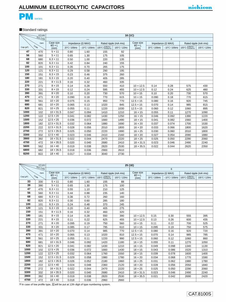
CAT.8100S
ALUMINUM ELECTROLYTIC CAPACITORS
PM series
Standard ratings
47566882
100120150180220270330390470560680820
100012001500180022002700330039004700560068008200
470560680820101121151181221271331391471561681821102122152182222272332392472562682822
5 × 115 × 11
6.3 × 116.3 × 116.3 × 116.3 × 116.3 × 156.3 × 15
8 × 11.58 × 158 × 158 × 208 × 20
10 × 2010 × 2010 × 2510 × 31.5
12.5 × 2012.5 × 2512.5 × 31.512.5 × 31.512.5 × 35.512.5 × 40
16 × 31.516 × 35.516 × 4018 × 35.518 × 40
0.800.650.500.420.350.290.230.200.160.140.120.100.0900.0750.0650.0550.0470.0410.0360.0320.0280.0250.0230.0220.0200.0190.0180.017
1.601.301.000.840.700.580.460.400.320.280.240.200.180.150.130.110.0940.0820.0720.0640.0560.0500.0460.0440.0400.0380.0360.034
155175220240265290375405460550595730770950
10201220141014301660188020102220241024702680282029003040
92105135155175195260285335410455570615770845
1030121012501490169018001990216022202410253026102730
.010 × 12.5
.010 × 12.5
.010 × 15.0
.010 × 15.012.5 × 15.012.5 × 15.012.5 × 15.0
16 × 15.016 × 15.018 × 15.016 × 20.016 × 20.016 × 25.018 × 20.018 × 25.018 × 31.518 × 35.5
0.140.120.100.0900.0800.0700.0600.0550.0460.0410.0370.0330.0300.0270.0250.0230.022
0.280.240.200.180.160.140.120.110.0920.0820.0740.0660.0600.0540.0500.0460.044
575625730770920985
10601270139015601700180020102090229024902620
430480570615745815895
1090122014001530162018001880206022402350
—16 (1C)
Case sizeφD × L(mm)
Impedance (Ω MAX)
20°C / 100kHz –10°C / 100kHz 105°C / 105°C / 120Hz
Rated ripple (mA rms)
6
Case sizeφD × L(mm)
Impedance (Ω MAX)
20°C / 100kHz –10°C / 100kHz 105°C / 105°C / 120Hz
Rated ripple (mA rms)
333947566882
100120150180220270330390470560680820
100012001500180022002700330039004700
330390470560680820101121151181221271331391471561681821102122152182222272332392472
5 × 115 × 11
6.3 × 116.3 × 116.3 × 116.3 × 116.3 × 156.3 × 15
8 × 11.58 × 158 × 158 × 208 × 20
10 × 2010 × 2010 × 2510 × 31.5
12.5 × 2012.5 × 2512.5 × 2512.5 × 31.512.5 × 35.512.5 × 40
16 × 31.516 × 35.516 × 4018 × 40
0.800.650.550.440.360.300.240.200.160.140.110.0950.0850.0700.0650.0550.0460.0410.0360.0320.0290.0260.0240.0220.0200.0190.018
1.601.301.100.880.720.600.480.400.320.280.220.190.170.140.130.110.0920.0820.0720.0640.0580.0520.0480.0440.0400.0380.036
155175210235260285370405460550625750795985
1020122014201430166017601980218023602470268028202960
88100125140160180245275320390455560610770810990
11801210143015501780196021202220241025302660
10 × 12.510 × 12.510 × 1510 × 15
12.5 × 1512.5 × 1512.5 × 15
16 × 1516 × 1518 × 1518 × 1516 × 2016 × 2518 × 2018 × 2518 × 31.518 × 35.5
0.150.130.110.0950.0800.0700.0600.0550.0490.0430.0390.0340.0310.0280.0250.0230.021
0.300.260.220.190.160.140.120.110.0980.0860.0780.0680.0620.0560.0500.0460.042
555600700750920985
10601270134015201600177019802050229024902690
395435525575720785860
1050113013101400159017801840206022402420
—
25 (1E)
Case sizeφD × L(mm)
Impedance (Ω MAX)
20°C / 100kHz –10°C / 100kHz 105°C / 105°C / 120Hz
Rated ripple (mA rms)
6Case size
φD × L(mm)
Impedance (Ω MAX)
20°C / 100kHz –10°C / 100kHz 105°C / 105°C / 120Hz
Rated ripple (mA rms)
10kHz~200kHz
10kHz~200kHz
10kHz~200kHz
10kHz~200kHz
Cap.(µF)
Size Code
Size Code
I tem
V(Code)
V(Code)
Code
CodeCap.(µF)
I tem
In case of low profile type, will be put at 12th digit of type numbering system.6

CAT.8100S
PM series
Standard ratings
2227333947566882
100120150180220270330390470560680820
1000120015001800220027003300
220270330390470560680820101121151181221271331391471561681821102122152182222272332
5 × 115 × 11
6.3 × 116.3 × 116.3 × 116.3 × 116.3 × 156.3 × 15
8 × 11.58 × 158 × 158 × 208 × 20
10 × 2010 × 2010 × 2510 × 31.5
12.5 × 2012.5 × 2512.5 × 2512.5 × 31.512.5 × 35.512.5 × 40
16 × 31.516 × 35.516 × 4018 × 40
0.750.600.490.410.340.280.240.190.160.140.120.100.0850.0700.0600.0550.0460.0410.0360.0320.0290.0260.0240.0220.0200.0180.017
1.501.200.980.820.680.560.480.380.320.280.240.200.170.140.120.110.0920.0820.0720.0640.0580.0520.0480.0440.0400.0360.034
160180225245270295370415460550595730795985
1060122014201430166017601980218023602470268029003040
8599
125140160180230265305370415520580735810955
11301160137014901710192021202220241026102730
10 × 12.510 × 12.510 × 1510 × 15
12.5 × 1512.5 × 1512.5 × 15
16 × 1516 × 1518 × 1518 × 1516 × 2016 × 2518 × 2018 × 2518 × 31.518 × 35.5
0.150.120.110.0900.0800.0650.0600.0550.0480.0420.0380.0340.0310.0280.0250.0230.021
0.300.240.220.180.160.130.120.110.0960.0840.0760.0680.0620.0560.0500.0460.042
555625700770920
102010601270136015401620177019802050229024902690
375435500560690780825
1010110012701370153017401840206022402420
—35(1V)
10kHz~200kHz
10kHz~200kHz
0.470.6811.52.23.34.76.8
101215182227333947566882
100120150180220270330390470560680820
10001200150018002200
R47R680101R52R23R34R76R8100120150180220270330390470560680820101121151181221271331391471561681821102122152182222
5 × 115 × 115 × 115 × 115 × 115 × 115 × 115 × 115 × 115 × 115 × 115 × 11
6.3 × 116.3 × 116.3 × 116.3 × 116.3 × 156.3 × 15
8 × 11.58 × 158 × 208 × 20
10 × 2010 × 2010 × 2510 × 31.510 × 31.5
12.5 × 2512.5 × 2512.5 × 31.512.5 × 35.512.5 × 40
16 × 31.516 × 35.516 × 4018 × 35.518 × 40
23.016.011.0
7.505.003.302.201.801.401.200.930.800.650.530.430.360.300.250.200.170.140.120.100.0850.0750.0650.0550.0480.0440.0400.0360.0330.0300.0280.0260.0250.024
46.032.022.015.010.0
6.604.403.602.802.401.861.601.301.060.860.720.600.500.400.340.280.240.200.170.150.130.110.0960.0880.0800.0720.0660.0600.0560.0520.0500.048
2228364554668191
115125145155195215240260330360410500620670820890
1040120013001440150016801850201021202260241024602560
111418222733404557627279
100115135150195220255320410455570635760900995
1120119013601530170018301990217022102300
10 × 12.510 × 1510 × 15
12.5 × 1512.5 × 1512.5 × 15
16 × 1516 × 1516 × 1518 × 1516 × 2016 × 2018 × 2018 × 2518 × 31.518 × 31.5
0.180.160.130.110.0950.0800.0700.0600.0550.0460.0440.0400.0360.0330.0310.029
0.360.320.260.220.190.160.140.120.110.0920.0880.0800.0720.0660.0620.058
510580640785845920
1120121012701470155016301810200021402220
330385435545605670840925990
1170126013501530173018801990
—
50 (1H)
Case sizeφD × L(mm)
Impedance (Ω MAX.)
20°C / 100kHz –10°C / 100kHz 105°C / 105°C / 120Hz
Rated ripple (mA rms)
6
Case sizeφD × L(mm)
Impedance (Ω MAX.)
20°C / 100kHz –10°C / 100kHz 105°C / 105°C / 120Hz
Rated ripple (mA rms)10kHz~200kHz
10kHz~200kHz
—
35 (1V)
Case sizeφD × L(mm)
Impedance (Ω MAX.)
20°C / 100kHz –10°C / 100kHz 105°C / 105°C / 120Hz
Rated ripple (mA rms)
6
Case sizeφD × L(mm)
Impedance (Ω MAX.)
20°C / 100kHz –10°C / 100kHz 105°C / 105°C / 120Hz
Rated ripple (mA rms)10kHz~200kHz
10kHz~200kHz
CodeCap.(µF)
I tem
Size code
V(Code)
CodeCap.(µF)
I tem
Size code
V(Code)
In case of low profile type, will be put at 12th digit of type numbering system.6
ALUMINUM ELECTROLYTIC CAPACITORS

CAT.8100S
Standard ratings
101215182227333947566882
100120150180220270330390470560680820
10001200
100120150180220270330390470560680820101121151181221271331391471561681821102122
..5 × 11
..5 × 116.3 × 11.6.3 × 11.6.3 × 11.6.3 × 11.6.3 × 15.6.3 × 15.
.....8 × 11.5..8 × 15..8 × 15..8 × 2010 × 2010 × 2010 × 25
...10 × 31.512.5 × 20...12.5 × 25...12.5 × 25...12.5 × 31.512.5 × 35.512.5 × 40......16 × 31.5...16 × 35.5
16 × 4018 × 40
1.060.930.730.630.520.430.350.300.250.210.170.150.120.100.0900.0750.0650.0550.0490.0430.0390.0350.0320.0290.0270.025
2.121.861.461.261.040.860.700.600.500.420.340.300.240.200.180.150.130.110.0980.0860.0780.0700.0640.0580.0540.050
135145185195215240305330365450500600750820950
11101140134014201620178019502050222023702510
677292
100110130170190215275315385495555665790835
100010901260142015801700188020502210
...10 × 12.5
...10 × 12.510 × 15
12.5 × 15...12.5 × 15...12.5 × 15...
16 × 1516 × 1518 × 1518 × 1516 × 2016 × 2518 × 2018 × 25
...18 × 31.5
...18 × 35.5
0.230.190.160.140.120.0950.0800.0700.0600.0500.0470.0420.0390.0350.0320.029
0.460.380.320.280.240.190.160.140.120.100.0940.0840.0780.0700.0640.058
450495580695750845
1050112012901410150017001730194021102280
275310375460510590750820965
1080117013501400161017801970
63 (1J)—
Case sizeφD × L(mm)
Impedance (Ω MAX.)
20°C / 100kHz –10°C / 100kHz
Rated ripple (mA rms)
105°C /10kHz~200kHz 105°C / 120Hz
Case sizeφD × L(mm)
Impedance (Ω MAX.)
20°C / 100kHz –10°C / 100kHz
Rated ripple (mA rms)
105°C /10kHz~200kHz 105°C / 120Hz
6
Code
V(Code)
Cap.(µF)
I tem
Size code
V(Code)
Code
Case size φD × L(mm)
Case size φD × L(mm)
Impedance (Ω MAX.) Impedance (Ω MAX.)Rated ripple (mA rms) Rated ripple (mA rms)
80 (1K)— 6
20°C / 100kHz 20°C / 100kHz–10°C / 100kHz –10°C / 100kHz105°C / 120Hz 105°C / 120HzCap.(µF)
Item
Size code
4.76.8
101215182227333947566882
100120150180220270330390470560680820
1000
4R76R8100120150180220270330390470560680820101121151181221271331391471561681821102
5 × 115 × 11
6.3 × 116.3 × 116.3 × 116.3 × 116.3 × 156.3 × 15
8 × 11.58 × 158 × 158 × 20
10 × 2010 × 2010 × 2510 × 31.510 × 31.5
12.5 × 2512.5 × 31.512.5 × 31.512.5 × 35.512.5 × 40
16 × 31.516 × 35.516 × 4018 × 35.518 × 40
4.202.601.701.401.201.000.770.630.530.460.390.340.280.250.210.180.150.130.120.100.0880.0780.0690.0620.0550.0490.044
11.007.004.603.803.202.702.101.701.401.201.100.920.760.680.570.490.410.350.320.270.240.210.190.170.150.130.12
53688796
104114135149234272295347426447526606663734816894
1000106014501600177018902080
2634434852587180
132156175208264284347406459520595667767822
11501300147015901790
10 × 12.510 × 12.510 × 15
12.5 × 1512.5 × 1512.5 × 15
16 × 1516 × 1516 × 1518 × 1516 × 2016 × 2518 × 2018 × 2518 × 31.518 × 31.5
0.490.420.360.310.270.230.200.180.150.130.110.0990.0890.0800.0720.065
1.301.100.970.840.730.620.540.470.410.350.300.270.240.220.190.18
271293337402430466663699766881995
11401170133014901560
155174202249273308444484543643742874908
106012101300
105°C / 10kHz ~200kHz 105°C / 10kHz ~
200kHz
In case of low profile type, will be put at 12th digit of type numbering system. 6
PM series
ALUMINUM ELECTROLYTIC CAPACITORS
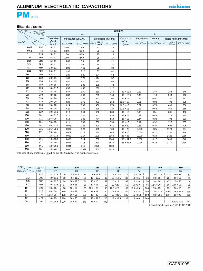
CAT.8100S
ALUMINUM ELECTROLYTIC CAPACITORS
PM series
Standard ratings
Code
Case size φD × L(mm)
Case size φD × L(mm)
Impedance (Ω MAX.) Impedance (Ω MAX.)Rated ripple (mA rms) Rated ripple (mA rms)
100 (2A)— 6
20°C / 100kHz 20°C / 100kHz–10°C / 100kHz –10°C / 100kHz105°C / 120Hz 105°C / 120HzCap.(µF)
Size code
0.470.6811.52.23.34.76.8
101215182227333947566882
100120150180220270330390470560680
R47
R68
010
1R5
2R2
3R3
4R7
6R8
100
120
150
180
220
270
330
390
470
560
680
820
101
121
151
181
221
271
331
391
471
561
681
5 × 11
5 × 11
5 × 11
5 × 11
5 × 11
5 × 11
6.3 × 11
6.3 × 11
6.3 × 11
6.3 × 11
6.3 × 15
6.3 × 15
8 × 11.5
8 × 15
8 × 15
8 × 20
10 × 20
10 × 20
10 × 25
10 × 31.5
10 × 31.5
12.5 × 25
12.5 × 25
12.5 × 31.5
12.5 × 35.5
12.5 × 40
16 × 31.5
16 × 35.5
16 × 40
18 × 35.5
18 × 40
43.0
23.0
17.0
10.0
6.60
4.10
2.80
1.90
1.20
1.00
0.81
0.67
0.55
0.47
0.38
0.33
0.28
0.24
0.21
0.18
0.15
0.13
0.11
0.098
0.087
0.072
0.062
0.053
0.047
0.041
0.036
116.0
62.0
46.0
27.0
18.0
11.0
7.60
5.10
3.20
2.70
2.20
1.80
1.50
1.30
1.00
0.89
0.76
0.65
0.57
0.49
0.41
0.35
0.30
0.26
0.23
0.19
0.17
0.14
0.13
0.11
0.097
17
23
27
35
43
54
68
83
104
114
131
155
230
269
299
352
423
456
526
606
663
774
798
904
1000
1130
1520
1730
1920
2070
2300
8
11
13
17
21
27
34
41
52
57
65
73
122
146
169
202
252
274
326
386
438
519
553
641
730
843
1160
1340
1530
1680
1910
10 × 12.5
10 × 12.5
10 × 15
12.5 × 15
12.5 × 15
12.5 × 15
16 × 15
16 × 15
16 × 15
18 × 15
16 × 20
16 × 25
18 × 20
18 × 25
18 × 31.5
18 × 35.5
0.50
0.42
0.36
0.31
0.27
0.23
0.19
0.17
0.14
0.12
0.11
0.093
0.080
0.070
0.062
0.056
1.40
1.10
0.97
0.84
0.73
0.62
0.51
0.46
0.38
0.32
0.30
0.25
0.22
0.19
0.17
0.15
268
293
337
402
430
466
681
719
793
917
995
1170
1230
1420
1600
1770
145
166
193
239
258
289
433
475
531
635
706
854
918
1080
1240
1410
105°C / 10kHz ~200kHz 105°C / 10kHz ~
200kHz
12.23.34.7
10223347
100
010
2R2
3R3
4R7
100
220
330
470
101
8 × 11.5
8 × 11.5
10 × 12.5
10 × 12.5
10 × 15
12.5 × 20
12.5 × 25
16 × 25
16 × 35.5
19
30
50
57
90
140
175
220
330
2CCap.(µF)
Rated Ripple (mA rms) at 105°C 120Hz
1602D
2002E
2502F
3152V
3502G
4002W
450
8 × 11.5
8 × 11.5
10 × 12.5
10 × 15
10 × 20
12.5 × 25
16 × 25
16 × 25
18 × 40
19
30
50
60
95
145
180
220
345
10 × 15
10 × 20
12.5 × 20
12.5 × 25
16 × 25
16 × 35.5
18 × 40
Case size
17
28
48
55
90
135
170
8 × 11.5
10 × 12.5
10 × 15
10 × 15
12.5 × 20
16 × 25
16 × 25
16 × 31.5
18 × 40
19
32
52
60
98
150
180
225
345
8 × 11.5
10 × 12.5
10 × 15
10 × 20
12.5 × 20
16 × 25
16 × 31.5
18 × 35.5
19
32
52
65
98
150
185
235
10 × 12.5
10 × 15
10 × 20
10 × 20
12.5 × 25
16 × 25
16 × 35.5
18 × 40
21
34
54
65
100
150
190
240
10 × 12.5
10 × 15
10 × 20
12.5 × 20
12.5 × 25
16 × 31.5
18 × 35.5
17
28
47
55
85
130
170
V(Code)
V(Code)
In case of low profile type, 6 will be put at 12th digit of type numbering system.
Item
Code

CAT.8100S
POSITIVE THERMISTORS "Posi-R"
General Observations1. Do not use"Posi-R" in the presence of oil or water.The parts could fail.2. Do not apply voltage in excess of the rated voltage- this could cause a short circuit or burn-out.3. Do not use "Posi-R" with reactive gas,reducing gas, or oxygen-free environment -electrical characteristics may deteriorate or
burn-out may occur.
Notes on Usage1. Please use the parts within the rated operating temperatures according to the catalog.2. Please use the parts wihtin the maximum operating voltage and maximum inrush current as specified in the catalog.3. The surface temperatures for the "Posi-R" during operation are :
for degaussing 110 to 120ûCfor overcurrent protection 100 to 160ûCPlease take into consideration the effect of generated heat around the PTC Thermistor.
4. Do not apply more lead stress than specified.5. Do not allow flux to come in contact with PTC,it may cause failure.6. The outer resin on the leads may be partially peeled off. This will not affect the function of products.
Notes on Storage1. Packaged parts should be stored under the following conditions :
temperature : 10 to +40ûChumidity : 85% or less
2. Prolonged storage of PTC devices may result in increased resistive characteristics. They will return to the initial value byapplying max. operating voltage prior to using the parts.
3. Shall be used shortly after opening the package. The prolonged exposure to the air may case to deteriorate the solderability.
APPLICATION GUIDELINES FOR POSITIVE THERMISTORS, "Posi-R"

Characteristics of Positive Thermistors "Posi-R"
Switching Temperature (Resistance Anomaly Point)At the resistance / temperature characteristics of positive thermistors "Posi-R", the temperature which the resistance value becomestwice as high as that of at 25ûC, is called as "switching temperature" (Curie point)Thermistors "Posi-R" show anomalous temperature characteristics of resistivity, and typical characteristics are represented in Fig. 1.Optimum characteristics can be selected for each application.
Temperature CoefficientThe temperature coefficient is calculated from the linear range at the steepest portion of resistance (T1~T2) as illustrated in Fig. 2.
Temperature coefficient =2.303 ( log10 R2 / R1) ×100 (%/ ûC)
t2 t1
Maximum Inrush CurrentThe maximum inrush current is the maximum allowable current (effective value) flowed into a Posi-R. No current higher than this shallbe flowed as it causes breakdown of a Posi-R.
Recovery TimeThe returning time is the time constant necessary for a Posi-R to quickly return to the switching temperature (resistance of twice ashigh as the initial value) after the power source is cut off.
Dissipation FactorWhen a power source is applied to Posi-R and thermal equilibrium will have been reached, the following equation is established.
V I = C (T1T0)
Where,V : Applied voltage (V)I : Equilibrium current (A)C : Dissipation factor (W/ ûC)T1 : Equilibrium temperature of Posi-R (ûC)T0 : Ambient temperature (ûC)
In case that the dissipation factor is known by putting arbitrary values of voltage and current into the above equation, the equilibriumtemperature at the then voltage can be attained.The temperature rise (T1 T0) of Posi-R due to voltage application can be also computed easily.
CAT.8100S
POSITIVE THERMISTORS "Posi-R"
105
104
103
102
10
1
10-1
50 0 50 100 150 200 250
Fig. 1 Resistance / Temperature Characteristics
Temperature (ûC)
BT CA CJBL CNCE
Res
ista
nce
ratio
(1
at 2
5ûC
)
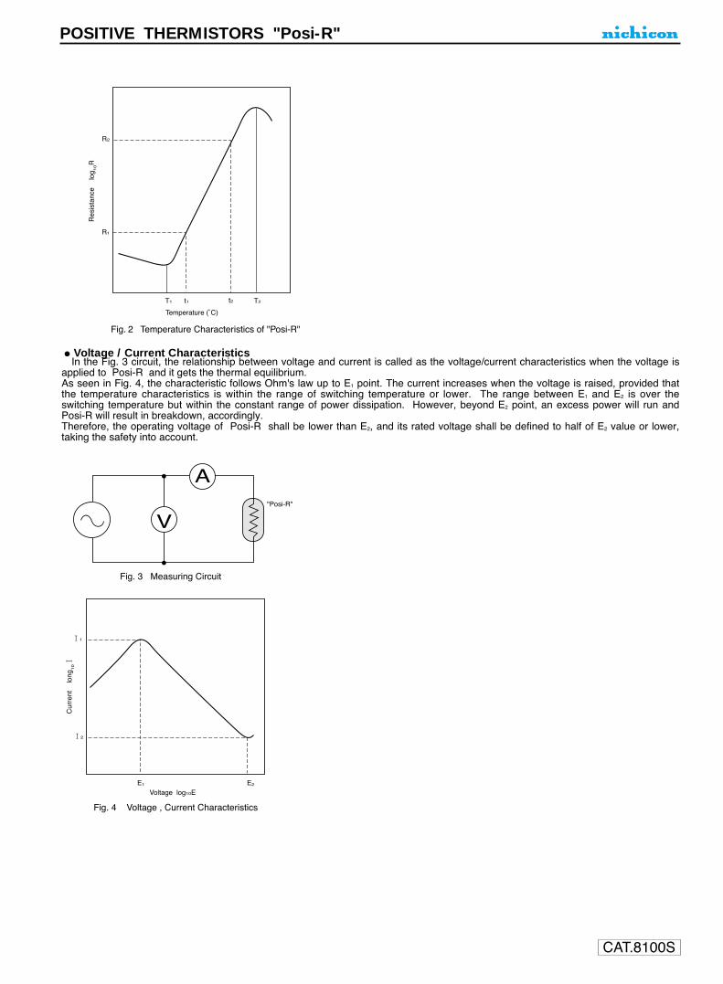
Voltage / Current CharacteristicsIn the Fig. 3 circuit, the relationship between voltage and current is called as the voltage/current characteristics when the voltage is
applied to Posi-R and it gets the thermal equilibrium.As seen in Fig. 4, the characteristic follows Ohm's law up to E1 point. The current increases when the voltage is raised, provided thatthe temperature characteristics is within the range of switching temperature or lower. The range between E1 and E2 is over theswitching temperature but within the constant range of power dissipation. However, beyond E2 point, an excess power will run andPosi-R will result in breakdown, accordingly.Therefore, the operating voltage of Posi-R shall be lower than E2, and its rated voltage shall be defined to half of E2 value or lower,taking the safety into account.
CAT.8100S
POSITIVE THERMISTORS "Posi-R"
V
A
Fig. 3 Measuring Circuit
"Posi-R"
Fig. 4 Voltage , Current Characteristics
Cur
rent
lo
ng101
11
12
E1 E2
Voltage log10E
Fig. 2 Temperature Characteristics of "Posi-R"
Temperature (ûC)
Res
ista
nce
lo
g 10R
R2
R1
T1 t1 t2 T2

CAT.8100S
POSITIVE THERMISTORS "Posi-R"
Equilibrium Current, Equilibrium ResistanceThe current, which Posi-R gets thermal equilibrium with an arbitrary voltage application (for 30 seconds or longer), is called as theequilibrium current.Besides, the quotient which the applied voltage is divided by the equilibrium current is specified as the equilibrium resistance.
Current , Time CharacteristicsIn the Fig. 5 circuit, when a load resistance (R) and a Posi-R are connected in series and an arbitrary voltage higher than E1 in Fig. 4 isapplied, the Posi-R will have inherent temperature due to a current flowing through it. Its temperature rises as time passes by, and itexceeds the switching temperature in a certain time, resulting in a rapid damp of the current. The trip time can be adjusted by thecurrent volume as shown in Fig. 6.By making use of these characteristics, a Posi-R can be used for the following applications;
1. Timing circuit2. Switching use for motor starting3. Overcurrent protection
When the parameters of I1, t1, I2 and t2 in Fig. 6 are expressed in a logarithmic graph in the manner of Fig. 7, an almost linear graph isformed and the relationship between the circuit current and the trip time can be obtained.But, when a Posi-R is used for a timing application such as a timer, the voltage shall be appropriately applied for 30 seconds or lessas the changes of conditions may affect much more as time passes by.
Fig. 5 Measuring Circuit
Pos
i-R
R
A
Type numbering system(Example for overcurrent protection 12V. 2.2Ω)
Z1
P2 3 4 5 6 7 8 9 10 11
Type (Posi-R)
Configuration
Revision Code
Switching Temperature (Example)
Usage
Nominal resistance
Temperature Code
BL
BN
BX
Nominal resistance Code
0.5Ω 0R5
1.0Ω 1R0
10Ω 100
100Ω 101
1kΩ 102
Application Code
For degaussing, lead type
For degaussing, Encased type
For overcurrent protection
Disc type
For square type temperature heater
For thermal sensing
For refrigerator motor starting
Others Appliance
B
K
C
D
S
P
For air conditioner R
M
Z
150ûC
160ûC
110ûC
190ûC
120ûC
135ûC
CC
CE
CH
C 1 1 C E 2 R 2 A

CAT.8100S
POSITIVE THERMISTORS "Posi-R"
For Overcurrent ProtectionWhen something abnormal occurs at the load such as a transistor circuit or a small-type motor, an abnormal current rushes into thepower source circuit. Then, a power transistor at the transformer or the switching power supply generates heat in an abnormal leveland causes breakdown.If a Posi-R for overcurrent protection is used in such a circuit, it can make the temperature compensation and protection for the powersource and the load. An example is as shown in Fig. 8.As to the temperature protection, it can be perfectly made in use of this Posi-R owing to the excellent characteristics of resistanceanomaly, that is, a current is reduced by the increased resistance due to the selfheating of Posi-R.At the voltage/current characteristics in Fig. 9, there is a peak current. If a current larger than this peak current flows, a Posi-R acts.But if a current less than the peak current flows, a Posi-R does not act. The peak current varies depending upon the size of Posi-R,resistance and ambient temperature. Fig. 10 shows an example of current characteristics.At the current higher than the upper limit of fluctuation range, a Posi-R acts. Contrary, at the current less than the lower limit, it doesnot act. But the fluctuation range varies owing to ambient temperature.For instance, if the operating temperature range is supposed to be at 10 ~ +60ûC, the lower limit at +60ûC becomes the maximumvalue for a normal current (non-acting) and the upper limit at 10ûC becomes the minimum value for a limiting current (acting),respectively.Judging from the above explained relations, a Posi-R can be suited for the circuit where the ratio of a limiting current to a normal currentis more than 2.5 ~ 3 times.
power source
power source
Load
Load
Power source circuit (Primary)
Motor circuit Transistor circuit
power source
Load
Power source circuit (Secondary)
Posi-R
Posi-R
Posi-R
Posi-R
Motor
Fig. 8 Examples of applications
M
Cur
rent
I1
I2
t1 t2
Time
Fig. 6 Current , Time Characteristics
Cur
rent
lo
g10I
I1
I2
t1 t2
Time log10t
Fig. 7 Current , Time Characteristics

CAT.8100S
POSITIVE THERMISTORS "Posi-R"
Cur
rent
(m
A)
1000
500
300
200
100
50
1 2 3 10 205
Voltage (VAC)
Fig. 9 Voltage / Current Characteristics
10ûC
25ûC
60ûC
Characteristics of ZPC4MCE100D
Peak current
Fluctuation range
Normal current (Non-acting)
Cur
rent
(m
A)
Characteristic of ZPC4MCE100D
600
400
300
500
200
100
10ûC 25ûC 60ûC
Ambient temperature
Fig. 10 Current Characteristics
Limiting current (Acting)
104
103
102
10
1
0.150 100 150 2000
Temperature (ûC)
Fig. 11 Resistance , Temperature Characteristics
Res
ista
nce
ratio
(1
at 2
5ûC
)

CAT.8100S
POSITIVE THERMISTORS "Posi-R"
For HeaterA disc type Posi-R is ideal for a small-power heater, making use of itsself-heating and self-equilibrium characteristics. As a Posi-R self-heatswhen voltage is applied, the size of a heater element and the switchingtemperature can be optionally selected in accordance with the shape ofappliances.Since this is of a non-contact control type, it is highly reliable for suchapplications.
Dimensions Disc type Square typeD : φ20mm max. W : 25mm max.T : 2 ~ 3mm L : 16mm max.
T : 1 ~ 3mm
Switching temperature 280ûC or lowerResistance For 100V : 100Ω or more
For 200V : 500Ω or more(Resistance value various by size.)
D W
L
T
electrode
T
electrode
Disc type Square type
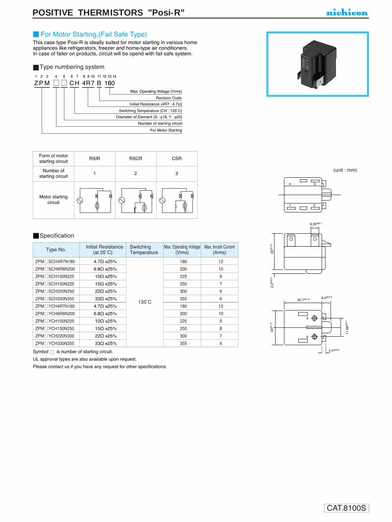
CAT.8100S
POSITIVE THERMISTORS "Posi-R"
Specification
Type numbering system
For Motor Starting,(Fail Safe Type)This case type Posi-R is ideally suited for motor starting in various home appliances like refrigerators, freezer and home-type air conditioners.In case of failer on products, circuit will be opend with fail safe system.
Form of motorstarting circuit
RSIR RSCR CSR
Number of starting circuit
Motor startingcircuit
1 2 3
Z P M CH 4R7 B 1801 2 3 4 5 6 7 8 9 10 11 12 13 14
Revision Code
Max. Operating Voltage (Vrms)
Initial Resistance (4R7 : 4.7Ω)
Switching Temperature (CH : 135ûC)
Diameter of Element (S : φ16, Y : φ20)
Number of starting circuit
For Motor Starting
(unit : mm)
25.7±1.0
3
5
6
4
1 2
25±
1.0
22±
1.0
11.6
6±0.1
6.35±0.1
6.0±0.5
2.5±0.2
2.2±
0.2
Type No. Initial Resistance(at 25ûC)
SwitchingTemperature
Max. Operating Voltage(Vrms)
Max. lnrush Current(Arms)
ZPM SCH4R7N180
ZPM SCH6R8N200
ZPM SCH100N225
ZPM SCH150N225
ZPM SCH220N250
ZPM SCH330N355
ZPM YCH4R7N180
ZPM YCH6R8N200
ZPM YCH100N225
ZPM YCH150N250
ZPM YCH220N300
ZPM YCH330N355
135ûC
180
200
225
250
300
355
180
200
225
250
300
355
12
10
9
7
6
6
12
10
9
8
7
6
4.7Ω ±25%
6.8Ω ±25%
10Ω ±25%
15Ω ±25%
22Ω ±25%
33Ω ±25%
4.7Ω ±25%
6.8Ω ±25%
10Ω ±25%
15Ω ±25%
22Ω ±25%
33Ω ±25%
Symbol is number of starting circuit.
UL approval types are also available upon request.
Please contact us if you have any request for other specifications.

CAT.8100S
POSITIVE THERMISTORS "Posi-R"
For Motor Starting
(unit : mm)
31±
1 15 9
9
3.5
33±
1
7.5
11.413
11
20±0.528±0.339±1
5φ2
φ4.5
Marking
R1
R1
51.
5
5
φ9
7.5
Max.OperatingVoltage(Vrms)
Max Current(Arms)
InitialResistance(at 25ûC )
Type No. Terminal
40Ω ±25%
47Ω ±25%
40Ω ±25%
300
250
300
300
500
8
12
9
10
13
#187 Tab Terminals
ZPR0YCE400C300
ZPR0YCE470A250
ZPR0YCE400A300
ZPR0YCE101A500 100Ω +30%20

CAT.8100S
BASIC ORDER UNIT
Series BulkTaping
Ammo-packFor Overcurrent Protection ZPC Type 500 1,000For Color TV Automatic ZPB Type 500
–––Degaussing Circuit ZPK Type 250
For Thermal SensingZPP35 Type 500
–––ZPP22 Type 200
POSITIVE THERMISTORS "Posi-R"

CAT.8100S
POSITIVE THERMISTORS "Posi-R"
ZPC42CE560A
ZPC45CE300B
ZPC49CE220A
ZPC4CCE150A
ZPC4MCE100A
ZPC4PCE6R8A
ZPC4RCE5R0A
ZPC59CE390A
ZPC5JCE270A
56Ω ±20%
30Ω ±20%
22Ω ±20%
15Ω ±20%
10Ω ±20%
6.8Ω ±20%
5Ω ±20%
39Ω ±20%
27Ω ±20%
140V
120V
265V
0.5A
0.7A
1.0A
1.1A
1.5A
1.8A
3.5A
0.8A
1.2A
65mA or less
100mA or less
130mA or less
160mA or less
210mA or less
260mA or less
290mA or less
100mA or less
140mA or less
160mA or more
250mA or more
340mA or more
410mA or more
540mA or more
660mA or more
730mA or more
250mA or more
350mA or more
7.0
8.7
10.4
11.7
15.3
16.2
16.8
10.0
14.0
6.0
3
2
3
5.0
10.0
5.0
10.0
0.5
0.6
0.65
0.6
ZPC32CE240D
ZPC35CE150A
ZPC3ACE8R2C
ZPC3DCE6R2C
ZPC3HCE4R7A
ZPC3MCE3R6A
ZPC3RCE3R0A
24Ω ±20%
15Ω ±20%
8.2Ω ±20%
6.2Ω ±20%
4.7Ω ±20%
3.6Ω ±20%
3.0Ω ±20%
60V
0.7A
0.9A
1.3A
1.5A
1.9A
2.2A
2.5A
100mA or less
130mA or less
190mA or less
220mA or less
270mA or less
310mA or less
370mA or less
250mA or more
320mA or more
480mA or more
560mA or more
690mA or more
790mA or more
920mA or more
6.5
8.0
10.1
11.4
13.0
14.7
15.9
4.5
1
3
2
3
5.0
10.0
0.5
0.6
ZPC25CE8R2A
ZPC29CE6R8A
ZPC29CE4R7A
ZPC2DCE4R7A
ZPC2DCE3R9A
ZPC2ECE3R9A
ZPC2ECE3R3A
ZPC2LCE2R7A
ZPC2LCE2R2A
ZPC2RCE2R2A
ZPC2RCE1R8A
8.2Ω ±20%
6.8Ω ±20%
4.7Ω ±20%
4.7Ω ±20%
3.9Ω ±20%
3.9Ω ±20%
3.3Ω ±20%
2.7Ω ±20%
2.2Ω ±20%
2.2Ω ±20%
1.8Ω ±20%
35V
1.3A
1.4A
1.6A
1.8A
1.9A
2.1A
2.2A
2.5A
2.8A
3.1A
3.4A
120mA or less
200mA or less
230mA or less
270mA or less
280mA or less
300mA or less
310mA or less
370mA or less
400mA or less
450mA or less
500mA or less
310mA or more
510mA or more
570mA or more
680mA or more
700mA or more
760mA or more
790mA or more
930mA or more
1020mA or more
1150mA or more
1250mA or more
8.0
9.7
9.7
11.4
11.4
11.9
11.9
14.3
14.3
15.9
15.9
3.5
5.0
10.0
0.5
0.63
Other current values are also available upon request.
For Overcurrent Protection
25V Class
50V Class
100V,120V,220V Class
ZPC11CE2R2A
ZPC12CE1R8A
ZPC13CE1R5B
ZPC15CE1R0B
ZPC17CE0R8B
ZPC1CCC0R5D
ZPC1MCC0R3B
2.2Ω ±20%
1.8Ω ±20%
1.5Ω ±20%
1.0Ω ±20%
0.8Ω ±20%
0.5Ω ±20%
0.3Ω ±20%
16V
2.1A
2.4A
3.0A
3.6A
4.1A
5.0A
7.0A
300mA or less
330mA or less
410mA or less
520mA or less
600mA or less
730mA or less
1030mA or less
760mA or more
830mA or more
1030mA or more
1300mA or more
1490mA or more
1830mA or more
2580mA or more
5.5
6.3
7.0
8.0
8.8
10.6
14.5
3.0 5.0
0.5
0.6
1
2
Type No.Initial Resistance
(at 25ûC)Max. Operating Voltage Max. Inrush Current
Normal Current ( 60ûC) Limiting Current (10ûC) D T F d
Current Characteristic Dimensions (mm)Fig.
Type No.Initial Resistance
(at 25ûC)Max. Operating Voltage Max. Inrush Current
Normal Current ( 60ûC) Limiting Current (10ûC) D T F d
Current Characteristic Dimensions (mm)Fig.
Type No.Initial Resistance
(at 25ûC)Max. Operating Voltage Max. Inrush Current
Normal Current ( 60ûC) Limiting Current (10ûC) D T F d
Current Characteristic Dimensions (mm)Fig.
Type No.Initial Resistance
(at 25ûC)Max. Operating Voltage Max. Inrush Current
Normal Current ( 60ûC) Limiting Current (10ûC) D T F d
Current Characteristic Dimensions (mm)Fig.
12V Class
Fig. 1 (Formed Lead Type : Y) Fig. 2 (Formed Lead Type : U)
D MAX. T MAX.
φd
25 M
IN.
F±1.5
7MA
X.
D MAX. T MAX.
φd
7MA
X.
F±1.5
25 M
IN.
Fig. 3 (Formed Straight)
T MAX.
φd
3MA
X.
D MAX.
F±1.5
: An internal element may be exposed. However, this would not affect the function of products.

CAT.8100S
POSITIVE THERMISTORS "Posi-R"
Features Examples of applications
For Overcurrent Protection in Telecommunications Equipment.
1 . This type responds quickly as having low heatcapacity.
2 . Noise shall not be generated as this is anon-contact type.
3 . Once "Posi-R" is operated, it keeps protecting unless switch is turned off.
4 . "Posi-R" returns to the original resistance levelby turning off the switch and can be used repeatedly, after abnormal conditions are removed. (There is no need to exchange.)
Posi-R
Posi-R
Fig.
ZPC2CBX1R0B
ZPC47BX100B
ZPC4RCE5R0A
ZPC4MCE100A
ZPC52CE121A
1Ω ±20%
10Ω ±20%
5Ω ±20%
10Ω ±20%
120Ω ±20%
2.4A
1.0A
3.5A
1.5A
0.3A
290mAp-p or less
100mAp-p or less
290mAp-p or less
210mAp-p or less
40mAp-p or less
900mAp-p or more
330mAp-p or more
730mAp-p or more
540mAp-p or more
100mAp-p or more
11.5
9.0
16.8
15.3
6.5
Type No.Initial Resistance
(at 25ûC)
Max.OperatingVoltage
Max. InrushCurrent Normal Current (60ûC) Limiting Current (10ûC) D T F d
Current Characteristic Dimensions (mm)
33V
56V
120V
140V
265V
3.5
5.0
6.0
5.0
5.0
10.0
5.0
0.5
0.6
0.65
0.5
0.6
2
1
3
1
Fig.

CAT.8100S
POSITIVE THERMISTORS "Posi-R"
In rush current limitation
(unit : mm)
Dimensions
14 1
10
0.4
18 1
18.2
1
9.5
4.51.0
Rated Voltage(Vrms)
Max.OperatingVoltage(Vrms)
InitialResistance(at 25°C )
Type No. Max Current
33Ω ±25%
40Ω ±25%
47Ω ±25%
100Ω ±25%
220 / 240276
280
4Arms (250V/30Ω)
8Arms (230V/20Ω)
12.5Arms (250V/100Ω)
15Arms (280V/20Ω)
ZPM0RCH330A250
ZPR0RCH400A250
ZPR0RCE470A250
ZPR0RCE101A250

CAT.8100S
POSITIVE THERMISTORS "Posi-R"
Taping Form
Taping Specifications for Automatic Insertion
Type numbering system
Z1
P2
C3
14
15
C6
E7
28
R9
210
A11
112
Y13
C14
Packing ( C : Ammo-Pack)
Formed Lead Type (Y, U)
Revision code
Pitch of Component (1 : 12.7mm, 3 : 25.4mm)
PD
H
d
WW0
W2
D0
W1L
F
t
T∆h
H0
P2
P1
P0R
PD
H
d
WW0
W2
D0
W1L
FH0
P2
P1
P0R
Packaging(Ammo-pack)
LW
H
Dimemsions
Nominal ToleranceSymbol Note
Diameter
Thickness
Lead dia
Pitch of component
Feed hole pitch
Hole center to lead
Feed hole center to component center
Lead to lead distance
Tilt of component
Tape width
Hold down tape width
Slip out of hole
Slip out of hole down tape
Height of component from tape center
Lead wire clinch height
Length of cut lead
Feed hole diameter
Total tape thickness
Cut length of rejected component
D
T
d
P
P0
P1
P2
F
∆h
W
W0
W1
W2
H
H0
R
φD0
t
L
Less φ12 Above φ12
12.7 25.4
12.7
3.85
6.35
5.0 7.5, 10.0
0
18.0
12.5
9.0
3.0
23.5
16.0
1.0
4.0
0.6
11.0
± 1.0
± 0.3
± 0.7
± 1.3
± 2.0
MIN.
MAX.
MAX.
± 0.5
MAX.
± 0.2
± 0.3
MAX
Subject to part DWG
Subject to part DWG
Subject to part DWG
Subject to part DWG+ 0.8 0.2
+ 1.0 0.5
+ 0.75 0.5
ItemDimensions (mm)
Symbol Dimension (mm)
H 230
L 330
W 50
Formed lead type (Y) Formed lead type (U)
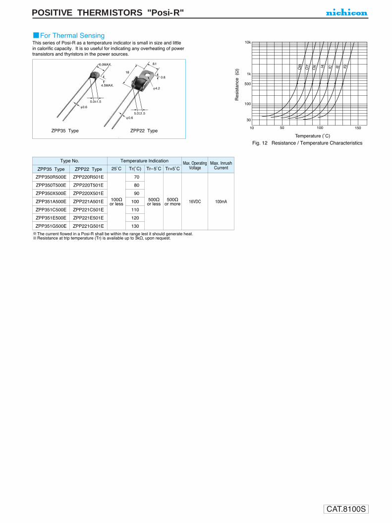
CAT.8100S
POSITIVE THERMISTORS "Posi-R"
For Thermal SensingThis series of Posi-R as a temperature indicator is small in size and little in calorific capacity. It is so useful for indicating any overheating of powertransistors and thyristors in the power sources.
8.1
0.8
φ4.2
6.0MAX.
4.5MAX.
φ0.6
φ0.6
5.0 1.5
18
5.0 1.5
10k
1k
500
100
30
10 50 100 150
OR
OT
OX IA IC IE IG
Res
ista
nce
(Ω
)
Temperature (ûC)
Fig. 12 Resistance / Temperature Characteristics
ZPP35 Type ZPP22 Type
ZPP350R500E ZPP220R501E 70
ZPP350T500E ZPP220T501E 80
ZPP350X500E ZPP220X501E 90
ZPP351A500E ZPP221A501E 100Ω 100 500Ω 500Ω 16VDC 100mA
ZPP351C500E ZPP221C501Eor less
110or less or more
ZPP351E500E ZPP221E501E 120
ZPP351G500E ZPP221G501E 130
The current flowed in a Posi-R shall be within the range lest it should generate heat.Resistance at trip temperature (Tr) is available up to 3kΩ, upon request.
Type No.
ZPP35 Type ZPP22 Type 25ûC Tr(ûC) Tr5ûC Tr+5ûC
Temperature Indication Max. OperatingVoltage
Max. InrushCurrent

CAT.8100S
POSITIVE THERMISTORS "Posi-R"
For Degaussing Circuit in Color CRT (Lead type)
Degaussing Posi-RDegaussing Posi-R
Degaussing coil Degaussing coil
Degaussing Posi-R
Degaussing coil
2 3
1
Automatic Degaussing Circuit (Single-element) Automatic Degaussing Circuit (Parallel-elements)Automatic Degaussing Circuit (Double-elements)
2
3
1
ZPB31 typeZPB45 type ZPB58 type
Lead type Dimensions
Specification
F 1.0 5.0
1.0
D MAX.
7.0
MA
X.
F 1.0
7.0
MA
X.
5.0
1.0
D MAX.
F 1.0
5.0
1.0
D MAX.
7.0
MA
X.
A Posi-R for a degaussing circuite in color TV is applicable toeither single-element circuit paraller-element circuit and with highattenuation double-element circuit
ZPB45BL3R0A
ZPB45BL7R0A
ZPB45BL100M
ZPB58BL5R0B
ZPB31BL3R0C
ZPB58BL180B
ZPB58BL200A
ZPB31BL9R0A
100/120
220
140
265
30Ap-p or more
25Ap-p or more
20Ap-p or more
21Ap-p or more
26Ap-p or more
16Ap-p or more
15Ap-p or more
19Ap-p or more
300mAp-p or less
300mAp-p or less
240mAp-p or less
300mAp-p or less
300mAp-p or less
200mAp-p or less
200mAp-p or less
250mAp-p or less
60mAp-p or less
60mAp-p or less
60mAp-p or less
60mAp-p or less
80mAp-p or less
40mAp-p or less
40mAp-p or less
50mAp-p or less
120V
120V
120V
120V
100V
200V
200V
220V
3.5Ω
3.5Ω
5Ω
8.5Ω
5Ω
15Ω
15Ω
20Ω
D
12.5
12.5
12.5
14.5
16.5
14.5
14.5
16.5
F
5.0
5.0
7.5
7.5
10.0
10.0
10.0
20Ap-p or more 220mAp-p or less 40mAp-p or less 220V 5Ω 14.5 10.0
10.0
Type No.
ZPB58BL300A
Rated Voltage(Vrms)
Max.OperatingVoltage(Vrms)
InitialResistance(at 25˚C )
Current Characteristics Conditions Dimensions(mm)
Inrush 3 seconds 60 seconds Rated Voltage Load Resistane
3Ω +30%–20
3Ω +30%–20
18Ω +30%–20
20Ω +30%–20
30Ω +30%–20
9Ω +30%–20
7Ω +30%–20
5Ω +30%–20
10Ω ±30%
UL-1434 approval type is also available upon request.
Other specification types are also available upon request.
(unit : mm)

CAT.8100S
POSITIVE THERMISTORS "Posi-R"
For Degaussing Circuit in Color CRT (Encased type)
Dimensions
Double-elements type and Parallel-elements typeSingle-element type
Specification
• Double-elements type
• Parallel-elements type
14 1
10
0.4
18 1
18.2
1
9.5
4.51.0
14 118 1
18.2
1
9.5
4.5
5 5
1.0 0.4
5
(unit : mm)
Other specification types are also available upon request.
ZPK68BL3R0B
ZPK68BL5R0A
ZPK68BL9R0B
17Ap-p or more
35Ap-p or more
20Ap-p or more
300mAp-p or more
300mAp-p or more
200mAp-p or more
70mAp-p or more
60mAp-p or more
50mAp-p or more
100V
120V
220V
10Ω
1Ω
20Ω
120 140
220/240 270
Type No. Rated Voltage(Vrms)
Max.OperatingVoltage(Vrms)
InitialResistance(at 25˚C )
Current Characteristics
Inrush 3 seconds 60 seconds
Conditions
Rated Voltage Load Resistane
3Ω +30%–20
5Ω ±20%
9Ω +30%–20
ZPK66BL3R0B
ZPK66BL5R0B
ZPK66BL7R0A
ZPK66BL9R0C
ZPK66BL180E
100/120
120
220
140
265
3Ω ±20%
5Ω ±20%
7Ω ±30%
9Ω ±30%
18Ω ±30%
18Ap-p or more
35Ap-p or more
20Ap-p or more
19Ap-p or more
20Ap-p or more
200mAp-p or more
300mAp-p or more
300mAp-p or more
200mAp-p or more
250mAp-p or more
15mAp-p or more
20mAp-p or more
7mAp-p or more
10mAp-p or more
10mAp-p or more
100V
100V
120V
220V
220V
8Ω
1Ω
2.7Ω
20Ω
10Ω
Type No.Rated Voltage
(Vrms)
Max.OperatingVoltage(Vrms)
InitialResistance(at 25˚C )
Current Characteristics
Inrush 3 seconds 60 seconds
Conditions
Rated Voltage Load Resistane
ZPK67BL1R5A
ZPK67BN4R5A
120
220
140
265
1.5Ω ±20%
4.5Ω ±20%
30Ap-p or more
28Ap-p or more
250mAp-p or more
300mAp-p or more
100mAp-p or more
60mAp-p or more
100V
220V
7Ω
15Ω
Type No. Rated Voltage(Vrms)
Max.OperatingVoltage(Vrms)
InitialResistance(at 25˚C )
Current Characteristics
Inrush 3 seconds 60 seconds
Conditions
Rated Voltage Load Resistane
• Single-element type

CAT.8100S
ALUMINUM ELECTROLYTIC CAPACITORS
PS series
Miniature Sized, Low Impedance, For Switching Power Supplies
Wide temperature range type, miniature sized.
PS High Rippie CurrentHigh Reliablity PJ
Radial Lead Type
Specifications
Type numbering system (Example : 25V 470µF)
Category Temperature Range
Rated Voltage Range
Rated Capacitance Range
Capacitance Tolerance
Leakage Current
tan δ
Stability at Low Temperature
Endurance
Shelf Life
Marking
Performance CharacteristicsItem
–55 ~ +105˚C (6.3 ~ 100V), –40 ~ +105˚C (160 ~ 400V), –25 ~ +105˚C (450V)
6.3 ~ 450V
0.47 ~ 15000µF
±20% at 120Hz, 20˚C
Printed with white color letter on dark brown sleeve.
After leaving capacitors under no load at 105˚C for 1000 hours, they meet the specifiedvalue for endurance characteristics listed above.
Rated voltage (V) 6.3 ~ 100 160 ~ 450
Leakage current After 1 minute's application of rated voltage, leakage currentis not more than 0.03CV or 4 (µA) , whichever is greater.
CV <= 1000 : I= 0.1CV+40 (µA)max. (1 minute's)CV > 1000 : I= 0.04CV+100 (µA)max. (1 minute's)
Rated voltage (V)
tan δ (MAX.)6.30.24
100.20
160.16
250.14
350.12
500.10
630.09
1000.08
160 ~ 2500.15
315 · 3500.20
400 · 4500.25
For capacitance of more than 1000µF, add 0.02 for every increase of 1000µF Measurement frequency : 120Hz, Temperature : 20˚C
Measurement frequency : 120Hz
Z–55˚C / Z+20˚CRated voltage (V)
Impedance ratio
6.3 · 105——
16 · 254——
35 · 503——
63 · 100—32
160 · 200—43
250—63
315 · 350—84
400—106
450——15
Z–40˚C / Z+20˚CZ–25˚C / Z+20˚C
After an application of D.C. bias voltage plus the rated ripplecurrent for 3000 hours (2000 hours for D = 5 ~ 10) at 105˚C thepeak voltage shall not exceed the rated D.C. voltage, capacitorsmeet the characteristic requirements listed at right.
Frequency coefficient of rated ripple current
V
6.3 ~ 100
160 ~ 450
FrequencyCap.(µF)
.. ~ 47
100 ~ 220.
330 ~ 680.
.1000 ~ 15000
0.47 ~ 2200
330 ~ 470.
50Hz
—
0.30
0.57
0.75
0.80
0.90
120Hz
0.17
0.50
0.71
0.87
1.00
1.00
300Hz
0.40
0.65
0.82
0.96
1.25
1.10
1kHz
0.65
0.80
0.90
0.98
1.40
1.13
10kHz ~
1.00
1.00
1.00
1.00
1.60
1.15
U1
P2
S3
14
E5
46
77
18
M9
P10
D11 12
Configuration
Case size
Series name
Type
φd
Pressurerelief vent
φD
P
φd
5
2.0
0.5
6.3
2.5
0.5
8
3.5
0.6
10
5.0
0.6
12.5
5.0
0.6
16
7.5
0.8
18
7.5
0.8
20 22
10.0 10.0
1.0 1.0
25
12.5
1.0
0.5 0.5 0.5 0.5 0.5 0.5 0.5 0.5 1.0 1.0
15MIN 4MIN(φ6.3up)L+ MAX
φD+
M
AX
(L < 20) 1.5(L 20) 2.0
P±0
.5
Capacitance tolerance (±20%)
Rated Capacitance (470µF)
Rated voltage (25V)
Sleeve (P.E.T.)
φ D
5
Pb free lead finishingPb free PET sleeve
Sn-Pb lead finishingPVC sleeve contain Pb
DD DH
6.3 ED EH
8 · 10 PD PH
12.5 ~ 18 HD HH
20 ~ 25 RD RH
Configuration
Please contact to us if other configurations are required.
Leakage current
tan δCapacitance change
Initial specified value or less200% or less of initial specified valueWithin ±20% of initial value
Please refer to page 19, 20, 21 about the formed or taped product spec.Please refer to page 3 for the minimum order quantity.
(Through 100V only)
Dimension table in next pages.
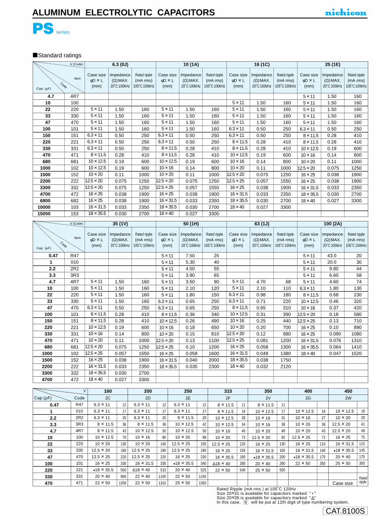
CAT.8100S
4.7 10223347
100 150 220 330 470 680
100015002200330047006800
10000 15000
4R7 100 220 330 470 101 151 221 331 471 681 102 152 222 332 472 682 103 153
5 × 115 × 115 × 115 × 11
6.3 × 116.3 × 116.3 × 11
8 × 11.510 × 12.510 × 12.510 × 20
12.5 × 2012.5 × 20
16 × 2516 × 2516 × 31.518 × 35.5
1.501.501.501.500.500.500.500.280.190.190.110.075 0.075 0.038 0.038 0.033 0.030
160 160 160 160 250 250 250 410 600 600
1000125012501900190023502700
6.3 (0J)
Case size φD × L(mm)
Impedance(Ω)MAX.
20˚C 100kHz
Rated ripple(mA rms)
105˚C 100kHz
V (Code)
ItemCode
Standard ratings D×L (mm)
PS series
ALUMINUM ELECTROLYTIC CAPACITORS
5 × 115 × 115 × 115 × 11
6.3 × 116.3 × 11
8 × 11.58 × 11.5
10 × 12.510 × 1610 × 20
12.5 × 2012.5 × 25
16 × 2516 × 31.518 × 35.518 × 40
1.501.501.501.500.500.500.280.280.190.140.110.075 0.057 0.038 0.033 0.030 0.027
160 160 160 160 250 250 410 410 600 800
1000125015501900235027003300
10 (1A)
Case size φD × L(mm)
Impedance(Ω)MAX.
20˚C 100kHz
Rated ripple(mA rms)
105˚C 100kHz
5 × 115 × 115 × 115 × 11
6.3 × 116.3 × 11
8 × 11.58 × 11.5
10 × 12.510 × 1610 × 20
12.5 × 2012.5 × 25
16 × 2516 × 31.518 × 35.518 × 40
1.501.501.501.500.500.500.280.280.190.140.110.075 0.057 0.038 0.033 0.030 0.027
160 160 160 160 250 250 410 410 600 800
1000125015501900235027003300
16 (1C)
Case size φD × L(mm)
Impedance(Ω)MAX.
20˚C 100kHz
Rated ripple(mA rms)
105˚C 100kHz
5 × 115 × 115 × 115 × 115 × 11
6.3 × 118 × 11.58 × 11.5
10 × 12.510 × 1610 × 20
12.5 × 2016 × 2516 × 2516 × 31.518 × 35.518 × 40
1.501.501.501.501.500.500.280.280.190.140.110.075 0.038 0.038 0.033 0.030 0.027
160 160 160 160 160 250 410 410 600 800
1000125019001900235027003300
25 (1E)
Case size φD × L(mm)
Impedance(Ω)MAX.
20˚C 100kHz
Rated ripple(mA rms)
105˚C 100kHz
0.471 2.2 3.3 4.7
10223347
100 150 220 330 470 680
10001500220033004700
R47 010 2R2 3R3 4R7 100 220 330 470 101 151 221 331 471 681 102 152 222 332 472
5 × 115 × 115 × 115 × 11
6.3 × 118 × 11.58 × 11.5
10 × 12.510 × 1610 × 20
12.5 × 2012.5 × 25
16 × 2516 × 31.518 × 35.518 × 40
1.501.501.501.500.500.280.280.190.140.110.075 0.057 0.038 0.033 0.030 0.027
160 160 160 160 250 410 410 600 800
1000125015501900235027003300
35 (1V)
Case size φD × L(mm)
Impedance(Ω)MAX.
20˚C 100kHz
Rated ripple(mA rms)
105˚C 100kHz
V (Code)
ItemCode
5 × 115 × 115 × 115 × 115 × 115 × 115 × 11
6.3 × 116.3 × 11
8 × 11.510 × 12.510 × 1610 × 20
12.5 × 2012.5 × 25
16 × 2516 × 31.518 × 35.5
7.505.304.503.903.502.101.800.650.650.360.260.180.150.130.100.058 0.040 0.035
2540556590
120 150 250 250 340 490 650 810
11001200160020002300
50 (1H)
Case size φD × L(mm)
Impedance(Ω)MAX.
20˚C 100kHz
Rated ripple(mA rms)
105˚C 100kHz
5 × 115 × 11
6.3 × 116.3 × 11
8 × 11.510 × 12.510 × 1610 × 20
12.5 × 2012.5 × 25
16 × 2516 × 31.518 × 35.518 × 40
4.702.100.980.710.650.310.250.200.120.081 0.058 0.049 0.038 0.032
68110 180 220 310 390 440 700 980
12001300138017502120
63 (1J)
Case size φD × L(mm)
Impedance(Ω)MAX.
20˚C 100kHz
Rated ripple(mA rms)
105˚C 100kHz
5 × 115 × 115 × 115 × 115 × 11
6.3 × 118 × 11.5
10 × 12.510 × 16
12.5 × 2012.5 × 25
16 × 2516 × 2516 × 31.516 × 35.518 × 40
43.020.09.806.604.601.800.680.460.370.180.130.100.090 0.076 0.064 0.047
2030445874
130 230 320 420 580 710 890
1080131014101520
100 (2A)
Case size φD × L(mm)
Impedance(Ω)MAX.
20˚C 100kHz
Rated ripple(mA rms)
105˚C 100kHz
Rated Ripple (mA rms ) at 105˚C 120Hz Size 20×31 is available for capacitors marked " • "Size 20×35 is available for capacitors marked " ∆"In this case, 6 will be put at 12th digit of type numbering system.
0.4712.23.34.7
10223347
100220330470
R47
010
2R2
3R3
4R7
100
220
330
470
101
221
331
471
6.3 × 11
6.3 × 11
6.3 × 11
8 × 11.5
8 × 11.5
10 × 12.5
10 × 20
12.5 × 20
12.5 × 25
16 × 25
•18 × 35.5
20 × 40
22 × 50
12
17
25
36
43
70
130
180
220
330
500
900
1200
2C
1602D
2002E
2502F
3152V
3502G
4002W
450
6.3 × 11
6.3 × 11
6.3 × 11
8 × 11.5
10 × 12.5
10 × 16
10 × 20
12.5 × 25
12.5 × 25
16 × 31.5
∆18 × 40
22 × 40
22 × 50
12
17
25
36
50
80
140
190
220
335
515
1100
1310
10 × 12.5
10 × 20
12.5 × 20
12.5 × 20
16 × 25
16 × 31.5
•18 × 35.5
20 × 40
25 × 50
Case size
18
29
41
49
75
115
145
175
350
6.3 × 11
6.3 × 11
8 × 11.5
10 × 12.5
10 × 12.5
10 × 20
12.5 × 25
12.5 × 25
16 × 25
•18 × 35.5
20 × 40
22 × 50
25 × 50
12
17
29
42
50
88
155
190
230
340
525
1150
1350
8 × 11.5
8 × 11.5
10 × 12.5
10 × 12.5
10 × 16
10 × 20
12.5 × 25
16 × 25
16 × 35.5
∆18 × 40
22 × 50
11
16
28
34
45
72
120
155
190
285
540
8 × 11.5
10 × 12.5
10 × 16
10 × 16
10 × 20
12.5 × 20
16 × 25
16 × 31.5
•18 × 35.5
20 × 40
25 × 50
11
17
31
38
49
82
130
160
200
290
550
10 × 12.5
10 × 16
10 × 20
10 × 20
12.5 × 25
16 × 25
16 × 31.5
•18 × 35.5
22 × 50
16
27
36
43
72
110
140
170
350
Cap.(µF) Code
Cap. (µF)
Cap. (µF)
V
Ratedripple
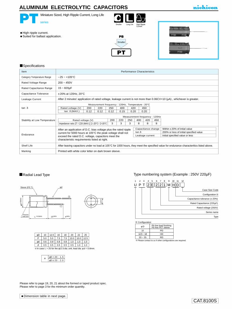
CAT.8100S
PT series
Miniature Sized, High Ripple Current, Long Life
High ripple current.Suited for ballast application.
ALUMINUM ELECTROLYTIC CAPACITORS
U1
P2
T3
24
E5
26
27
18
M9 10 11
Capacitance tolerance (± 20%)
Rated Capacitance (220µF)
Rated voltage (250V)
H D12
TCase Size Code
Series name
Type
φD
φD 20 : 2.0
φD < 20 : 1.5
P
10
5.0
12.5
5.0
16
7.5
18
7.5
20
10.0
φd 0.6
0.5
0.6
0.5
0.8
0.5
0.8
0.5
1.0
0.5
22
10.0
1.0
1.0
25
12.5
1.0
1.0
L + MAX 15 MIN 4 MIN
Radial Lead Type
Sleeve (P.E.T.) φ d
Pressurerelief vent
Type numbering system (Example : 250V 220µF)
Configuration
P±0
.5
φD+
M
AX
In case L > 25 for the φ12.5 dia. unit, lead dia. φ d = 0.8mm.
φ D
10
Pb free lead finishingPb free PET sleeve
PD
12.5 ~ 18 HD
20 ~ 25 RD
Configuration
Please contact to us if other configurations are required.
Dimension table in next page.
Please refer to page 19, 20, 21 about the formed or taped product spec.Please refer to page 3 for the minimum order quantity.
Specifications
Category Temperature Range
Rated Voltage Range
Rated Capacitance Range
Capacitance Tolerance
Leakage Current
tan δ
Stability at Low Temperature
Endurance
Shelf Life
Marking
Performance CharacteristicsItem
–25 ~ +105°C
200 ~ 450V
15 ~ 820µF
±20% at 120Hz, 20°C
After 2 minutes' application of rated voltage, leakage current is not more than 0.06CV+10 (µA) , whichever is greater.
Printed with white color letter on dark brown sleeve.
After leaving capacitors under no load at 105°C for 1000 hours, they meet the specified value for endurance characteritics listed above.
Measurement frequency : 120Hz
Capacitance change
Leakage current
After an application of D.C. bias voltage plus the rated ripplecurrent for 5000 hours at 105°C the peak voltage shall notexceed the rated D.C. voltage, capacitors meet thecharacteristic requirements listed at right.
tan δWithin ±20% of initial value
Initial specified value or less200% or less of initial specified value
Z–25°C / Z+20°CRated voltage (V)
Impedance ratio ZT / Z20 (MAX.)2003
2203
2503
4008
4208
4508
Measurement frequency : 120Hz, Temperature : 20°C
Rated voltage (V)tan δ (MAX.)
2000.12
2200.12
2500.12
4200.20
4500.20
4000.15
PT
PB
Smaller

CAT.8100S
PT series
ALUMINUM ELECTROLYTIC CAPACITORS
V
10 × 31.5
12.5 × 25
12.5 × 31.5
12.5 × 31.5
12.5 × 35.5
12.5 × 40
16 × 31.5
18 × 31.5
16 × 35.5
18 × 31.5
18 × 35.5
18 × 40
22 × 40
22 × 50
25 × 40
25 × 50
0.35
0.41
0.48
0.53
0.62
0.70
0.76
0.81
0.88
0.87
1.01
1.13
1.20
1.50
1.50
1.60
10 × 31.5
12.5 × 25
12.5 × 31.5
12.5 × 31.5
12.5 × 35.5
12.5 × 40
16 × 31.5
16 × 35.5
18 × 31.5
16 × 40
18 × 35.5
18 × 40
22 × 40
22 × 50
25 × 40
25 × 50
0.29
0.34
0.39
0.43
0.49
0.58
0.67
0.77
0.77
0.88
0.88
1.01
1.15
1.50
1.50
1.60
10 × 31.5
12.5 × 25
12.5 × 31.5
12.5 × 31.5
12.5 × 35.5
12.5 × 40
16 × 31.5
16 × 35.5
18 × 31.5
16 × 40
18 × 35.5
18 × 40
22 × 40
22 × 50
25 × 40
25 × 50
0.27
0.31
0.36
0.40
0.46
0.53
0.62
0.72
0.72
0.83
0.83
0.95
1.05
1.45
1.45
1.55
10 × 31.5
12.5 × 25
12.5 × 31.5
12.5 × 31.5
12.5 × 35.5
12.5 × 40
16 × 31.5
16 × 31.5
16 × 35.5
18 × 31.5
16 × 40
18 × 35.5
18 × 40
22 × 40
22 × 50
25 × 40
25 × 50
0.21
0.24
0.29
0.32
0.37
0.42
0.46
0.50
0.58
0.58
0.66
0.67
0.77
0.85
1.30
1.30
1.40
10 × 31.5
12.5 × 25
12.5 × 31.5
12.5 × 31.5
12.5 × 35.5
12.5 × 40
16 × 31.5
16 × 35.5
18 × 31.5
16 × 40
18 × 31.5
18 × 35.5
18 × 40
22 × 40
22 × 50
25 × 40
25 × 50
0.17
0.20
0.24
0.27
0.31
0.36
0.43
0.51
0.51
0.57
0.57
0.61
0.66
0.80
0.95
0.95
1.20
10 × 31.5
12.5 × 25
12.5 × 31.5
12.5 × 31.5
12.5 × 35.5
12.5 × 40
16 × 31.5
16 × 35.5
16 × 40
18 × 31.5
18 × 35.5
18 × 40
22 × 40
22 × 50
25 × 40
25 × 50
0.15
0.18
0.22
0.25
0.28
0.32
0.38
0.44
0.49
0.48
0.55
0.65
0.77
0.92
0.92
1.10
2D 2P 2E 2G W6 2W
200 220 250 400 420 450
Case size
: Rated Ripple (A rms) at 105°C 120Hz: In this case, 6 will be put at 12th digit of type numbering system.
Frequency
Coefficient
50Hz
0.80
120Hz
1.00
300Hz
1.25
1kHz
1.40
10kHz~
1.60
D × L (mm)Dimensions
Frequency coefficient of rated ripple current
Cap Code
15
18
22
27
33
39
47
56
68
82
100
120
150
180
220
270
330
390
470
560
680
820
150
180
220
270
330
390
470
560
680
820
101
121
151
181
221
271
331
391
471
561
681
822
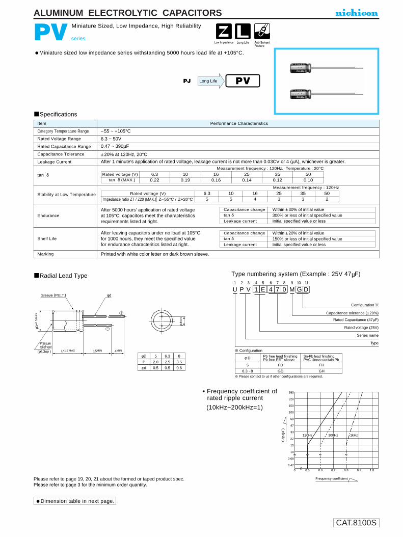
CAT.8100S
Frequency coefficient
Cap
.(µF
)
U1
P2
V3
14
E5
46
77
08
M9
G10
D11
Configuration
Capacitance tolerance (±20%)
Rated Capacitance (47µF)
Rated voltage (25V)
Series name
Type
390
220
150
100
68
47
33
22
15
10
0.68
0.47
0 0.5 0.6 0.7 0.8 0.9 1.0
300Hz 1kHz120Hz
Pressurerelief vent
L+1.5 MAX(φ6.3up ) 15MIN 4MIN
φd
φD+
0.5
MA
X
P±0
.5
φD
P
φd
5
2.0
0.5
6.3
2.5
0.5
8
3.5
0.6
φ D
5
Pb free lead finishingPb free PET sleeve
Sn-Pb lead finishingPVC sleeve contain Pb
FD FH
6.3 · 8 GD GH
Configuration
Sleeve (P.E.T.)
Please contact to us if other configurations are required.
ALUMINUM ELECTROLYTIC CAPACITORS
PV series
Miniature Sized, Low Impedance, High Reliability
Miniature sized low impedance series withstanding 5000 hours load life at +105°C.
Radial Lead Type
Specifications
Category Temperature Range
Rated Voltage Range
Rated Capacitance Range
Capacitance Tolerance
Leakage Current
tan δ
Stability at Low Temperature
Endurance
Shelf Life
Marking
Performance CharacteristicsItem
–55 ~ +105°C
6.3 ~ 50V
0.47 ~ 390µF
±20% at 120Hz, 20°C
After 1 minute's application of rated voltage, leakage current is not more than 0.03CV or 4 (µA), whichever is greater.
Printed with white color letter on dark brown sleeve.
After leaving capacitors under no load at 105°Cfor 1000 hours, they meet the specified valuefor endurance characteritics listed at right.
PVLong LifePJ
Capacitance change
Leakage current
tan δWithin ±20% of initial value
Initial specified value or less150% or less of initial specified value
Type numbering system (Example : 25V 47µF)
Measurement frequency : 120Hz, Temperature : 20°C
Measurement frequency : 120Hz
Capacitance change
Leakage current
After 5000 hours' application of rated voltageat 105°C, capacitors meet the characteristicsrequirements listed at right.
tan δWithin ±30% of initial value
Initial specified value or less300% or less of initial specified value
Rated voltage (V)tan δ (MAX.)
6.30.22
100.19
160.16
250.14
350.12
500.10
Z–55°C / Z+20°C
Rated voltage (V)
Impedance ratio ZT / Z20 (MAX.)6.35
105
164
253
353
502
• Frequency coefficient ofrated ripple current
(10kHz~200kHz=1)
Dimension table in next page.
Please refer to page 19, 20, 21 about the formed or taped product spec.Please refer to page 3 for the minimum order quantity.

CAT.8100S
333947566882
100 120 150 180 220 270 330 390
330 390 470 560 680 820 101 121 151 181 221 271 331 391
5 × 115 × 11
6.3 × 11...6.3 × 11...6.3 × 11......8 × 11.5...8 × 11.5...8 × 11.5
1.501.100.830.660.510.410.340.29
150 175 225 250 285 370 405 445
6.3 (0J)
Case size φD × L(mm)
Impedance(Ω) MAX.
20°C 100kHz
Rated ripple (mA rms)
105°C 100kHzCap.(µF)
V(Code)
ItemCode
Dimensions
PV series
ALUMINUM ELECTROLYTIC CAPACITORS
5 × 115 × 11
6.3 × 11...6.3 × 11...6.3 × 11...6.3 × 11......8 × 11.5...8 × 11.5...8 × 11.5
1.401.100.940.750.600.490.410.340.27
155 175 210 235 265 290 370 405 460
10 (1A)
Case size φD × L(mm)
Impedance(Ω) MAX.
20°C 100kHz
Rated ripple (mA rms)
105°C 100kHz
5 × 115 × 11
6.3 × 11...6.3 × 11...6.3 × 11...6.3 × 11......8 × 11.5...8 × 11.5...8 × 11.5
1.401.100.850.710.600.490.390.340.27
155 175 220 240 265 290 375 405 460
16 (1C)
Case size φD × L(mm)
Impedance(Ω) MAX.
20°C 100kHz
Rated ripple (mA rms)
105°C 100kHz
5 × 115 × 11
6.3 × 11...6.3 × 11...6.3 × 11...6.3 × 11......8 × 11.5...8 × 11.5...8 × 11.5
1.401.100.940.750.610.510.410.340.27
155 175 210 235 260 285 370 405 460
25 (1E)
Case size φD × L(mm)
Impedance(Ω) MAX.
20°C 100kHz
Rated ripple (mA rms)
105°C 100kHz
..0.47
..0.681...1.5 2.2 3.3 4.7 6.8
10.....12.....15.....18.....22.....27.....33.....39.....47.....56.....68.....82.....
100.......
R47 R68 010 1R5 2R2 3R3 4R7 6R8 100 120 150 180 220 270 330 390 470 560 680 820 101
35 (1V)
Case size φD × L(mm)
Impedance(Ω) MAX.
20°C 100kHz
Rated ripple (mA rms)
105°C 100kHzCap.(µF)
V(Code)
ItemCode
50 (1H)
Case size φD × L(mm)
Impedance(Ω) MAX.
20°C 100kHz
Rated ripple (mA rms)
105°C 100kHz
5 × 115 × 11
6.3 × 11...6.3 × 11...6.3 × 11...6.3 × 11......8 × 11.5...8 × 11.5...8 × 11.5
1.301.000.830.700.580.480.410.320.27
160 180 225 245 270 295 370 415 460
5 × 115 × 115 × 115 × 115 × 115 × 115 × 115 × 115 × 115 × 115 × 115 × 11
6.3 × 11...6.3 × 11...6.3 × 11...6.3 × 11......8 × 11.5...8 × 11.5...8 × 11.5
32.0....22.0....15.0....11.0....7.004.603.102.502.001.701.301.100.910.740.600.500.420.350.28
..22
..28
..36
..45
..54
..66
..81
..91115 125 145 155 195 215 240 260 330 360 410

CAT.8100S
Rated voltage (V)
15MIN 4MIN
φd
φD
P
φd
4
1.5
0.45
5
2.0
0.5
6.3
2.5
0.5
8
3.5
0.6
10
5.0
0.6
12.5
5.0
0.6
16
7.5
0.8
18
7.5
0.8
U1
P2
W3
14
A5
66
87
18
M9
P10
D11 12
Configuration
Size code
Capacitance tolerance (±20%)
Rated Capacitance (680µF)
Rated voltage (10V)
Series name
Type
(0.45) (0.45) 0.8
(L = 7) 1.0(L < 20) 1.5(L 20) 2.0
Pressure relief vent
φ6.3up (No pressure relief vent for 7mmL products)
: Applied to L>25 products( ): Applied to 7mmL products
L+ MAX
P±0
.5
20 22
10.0 10.0
1.0 1.0
25
12.5
1.0
0.5 0.5 0.5 0.5 0.5 0.5 0.5 0.5 0.5 1.0 1.0
φD+
M
AX
Sleeve (P.E.T.)
φ D Pb free lead finishingPb free PET sleeve
Sn-Pb lead finishingPVC sleeve contain Pb
4 · 5 DD DH
6.3 ED EH (7mm L : DH)
8 · 10 PD PH
12.5 ~ 18 HD HH
Configuration
20 ~ 25 RD RH
Please contact to us if other configurations are required.
PW series
Low lmpedance, High ReliabilityFor Switching Power Supplies
Radial Lead Type Type numbering system (Example : 10V 680µF)
Smaller case size and lower impedance than PM series.Low impedance and high reliability withstanding 2000 hours to 8000 hours.Capacitance ranges available based on the numerical values in E12 series under JIS.
Dimension table in next page.
Specifications
Category Temperature Range
Rated Voltage Range
Rated Capacitance Range
Capacitance Tolerance
Leakage Current
tan δ
Stability at Low Temperature
Endurance
Shelf Life
Marking
Performance CharacteristicsItem
–55 ~ +105˚C (6.3 ~ 100V), –40 ~ + 105˚C (160 ~ 400V), –25 ~ +105˚C (450V)
6.3 ~ 450V
0.47 ~ 15000µF
±20% at 120Hz, 20˚C
Printed with white color letter on dark brown sleeve.
After leaving capacitors under no load at 105˚C for 1000 hours, they meet the specified value for endurance characteristics listed
Rated voltage (V) 6.3 ~ 100 160 ~ 450
Leakage current After 1 minute's application of rated voltage, leakage currentis not more than 0.03CV or 4 (µA), whichever is greater.
CV <= 1000 : I = 0.1CV+40 (µA) max. (1 minute's)CV > 1000 : I = 0.04CV+100 (µA) max. (1 minute's)
tan δ (MAX.)6.30.22
100.19
160.16
250.14
350.12
500.10
630.09
1000.08
160 ~ 2500.15
315 · 3500.20
400 · 4500.25
For capacitance of more than 1000µF, add 0.02 for every increase of 1000µF. Measurement frequency : 120Hz, Temperature : 20˚C
120Hz
Z–55˚C / Z+20˚CRated voltage (V)
Impedance ratio
6.3 · 103——
16 · 253——
35 · 503——
63 · 1003——
160 · 200—43
250—63
315 · 350—84
400—106
450——15
Z–40˚C / Z+20˚CZ–25˚C / Z+20˚C
After an application of D.C. bias voltage plus the rated ripplecurrent for 8000 hours (2000 hours for D = 4, 5 and 6.3,3000 hours for D = 8, 5000 hours for D = 10, 7000 hours forD = 12.5) at 105˚C the peak voltage shall not exceed therated D.C.voltage, capacitors meet the characteristicrequirements listed at right.
Frequency coefficient of rated ripple current
V
6.3 ~ 100
160 ~ 450
FrequencyCap. (µF)
..~ 56
68 ~ 330.
390 ~ 1000.
.1200 ~ 15000
0.47 ~ 2200
330 ~ 470.
50Hz
0.20
0.55
0.70
0.80
0.80
0.90
120Hz
0.30
0.65
0.75
0.85
1.00
1.00
300Hz
0.50
0.75
0.80
0.90
1.25
1.10
1kHz
0.80
0.85
0.90
0.95
1.40
1.13
10kHz ~
1.00
1.00
1.00
1.00
1.60
1.15
Leakage current
tan δCapacitance change
Initial specified value or less200% or less of initial specified valueWithin ±20% of initial value
PW
PMSmaller
ALUMINUM ELECTROLYTIC CAPACITORS
Please refer to page 19, 20, 21 about the formed or taped product spec.Please refer to page 3 for the minimum order quantity.

CAT.8100S
ALUMINUM ELECTROLYTIC CAPACITORS
PW series
22
27
33
39
47
5668
82
100
120
150
180
220
330
470560
680
820
1000
1200
1500
2200
2700
3300
3900
4700
5600
6800
8200
10000
1200015000
220
270
330
390
470
560680
820
101
121
151
181
221
331
471561
681
821
102
122
152
222
272
332
392
472
562
682
822
103
123153
0.60
2.000.600.95
0.600.950.951.30
0.60
0.450.250.50
0.25
0.250.230.1170.117
0.090
0.0850.090
0.090
0.0650.068
0.052
0.0380.0450.035
0.038
0.030
0.0220.0250.0220.0290.0220.028
0.018
0.0160.0200.0160.015
1.20
5.001.202.40
1.202.402.402.60
1.20
1.200.501.00
0.50
0.500.460.2340.234
0.18
0.170.18
0.18
0.130.136
0.104
0.0760.0900.070
0.076
0.060
0.0440.0500.0440.0580.0440.056
0.036
0.0320.0400.0320.030
180
65180120
180120120120
180
200290235
290
290430555555
755
730755
755
9951050
1220
165514401815
1655
1945
255523102510220525552490
3010
3150274036353680
5 × 114 × 7
5 × 115 × 75 × 75 × 114 × 11
5 × 116.3 × 7
5 × 115 × 15
6.3 × 11
6.3 × 116.3 × 116.3 × 15
8 × 11.5
8 × 11.5
10 ×12.58 × 15
10 × 168 × 20
10 × 20
10 × 2010 × 25
12.5 × 2010 × 31.5
12.5 × 2512.5 × 2512.5 × 31.512.5 × 35.5
16 × 20
16 × 25
16 × 2518 × 2016 × 31.518 × 2516 × 35.518 × 31.5
18 × 35.5
18 × 40
0.602.00
0.600.950.950.601.30
0.600.450.600.50
0.25
0.250.250.23
0.117
0.117
0.0900.085
0.0680.065
0.052
0.0520.0450.0380.0350.0300.0300.0250.0220.029
0.022
0.0220.0280.0180.0200.0160.016
0.015
0.014
1.205.00
1.202.402.401.202.60
1.201.201.201.00
0.50
0.500.500.46
0.234
0.234
0.180.17
0.1360.13
0.104
0.1040.0900.0760.0700.0600.0600.0500.0440.058
0.044
0.0440.0560.0360.0400.0320.032
0.030
0.028
18065
180120120180120
180200180235
290
290290430
555
555
755730
1050995
1220
122014401655181519451945231025102205
2555
255524903010274031503635
3680
3800
Standard ratings6.3 (0J)
20˚C / 100kHz –10˚C / 100kHz
10 (1A)
20˚C / 100kHz –10˚C / 100kHz
: In this case, will be put at 12th digit of type numbering system.6
V (Code)
Item
CodeCap.(µF)
Case sizeφD × L(mm)
Rated ripple(mA rms)
105˚C / 100kHz
Case sizeφD × L(mm)
Impedance (Ω MAX.) Rated ripple(mA rms)
105˚C / 100kHz
Impedance (Ω MAX.)
5 × 11
4 × 75 × 115 × 7
5 × 115 × 75 × 74 × 11
5 × 11
6.3 × 76.3 × 11
5 × 15
6.3 × 11
6.3 × 116.3 × 15
8 × 11.58 × 11.5
10 × 12.5
8 × 1510 × 12.5
10 × 12.5
8 × 2010 × 16
10 × 20
12.5 × 2010 × 2510 × 31.5
12.5 × 20
12.5 × 25
16 × 2512.5 × 31.512.5 × 35.5
16 × 2016 × 2518 × 20
16 × 31.5
16 × 31.518 × 2518 × 31.518 × 35.5

CAT.8100S
ALUMINUM ELECTROLYTIC CAPACITORS
00004.7
00010
00015
00022
00027
00033
00039
00047
00056
000820010000120001500018000220
00330
00470
00560
00680
00820
01000
01200
01500
01800
02200
02700
03300
03900
04700
05600
068000820010000
4R7
100
150
220
270
330
390
470
560
820101121151181221
331
471
561
681
821
102
122
152
182
222
272
332
392
472
562
682822103
5 × 11
4 × 75 × 115 × 75 × 75 × 11
6.3 × 7
4 × 11
5 × 115 × 11
6.3 × 75 × 15
6.3 × 116.3 × 116.3 × 116.3 × 15
8 × 11.5
8 × 11.5
10 × 12.58 × 15
10 × 168 × 20
10 × 20
10 × 20
10 × 2512.5 × 20
10 × 31.5
12.5 × 25
12.5 × 31.516 × 2016 × 25
12.5 × 35.516 × 2518 × 2016 × 31.518 × 2516 × 35.518 × 31.518 × 35.518 × 35.518 × 40
0.60
2.000.600.950.950.600.45
1.30
0.600.600.450.500.250.250.250.230.117
0.117
0.0900.085
0.0680.0650.052
0.052
0.0450.0380.035
0.030
0.0250.0290.0220.0220.0220.0280.0180.0200.0160.0160.0150.0150.014
1.20
5.001.202.402.401.201.20
2.60
1.201.201.201.000.500.500.500.460.234
0.234
0.180.17
0.1360.130.104
0.104
0.0900.0760.070
0.060
0.0500.0580.0440.0440.0440.0560.0360.0400.0320.0320.0300.0300.028
180
65180120120180200
120
180180200235290290290430555
555
755730
1050995
1220
1220
144016551815
1945
2310220525552510255524903010274031503635368036803800
5 × 115 × 114 × 7
5 × 115 × 74 × 11
5 × 11
5 × 116.3 × 7
5 × 11
5 × 15
6.3 × 116.3 × 116.3 × 15
8 × 11.5
8 × 11.510 × 12.5
8 × 1510 × 16
8 × 2010 × 20
10 × 20
10 × 2512.5 × 20
10 × 31.5
16 × 2512.5 × 2512.5 × 31.5
16 × 2016 × 2518 × 20
12.5 × 35.5
16 × 25
16 × 31.518 × 2516 × 35.518 × 31.5
18 × 35.5
18 × 40
0.600.602.00
0.600.951.30
0.60
0.600.450.60
0.50
0.250.250.230.117
0.1170.0900.0850.0680.0650.052
0.052
0.0450.0380.035
0.0220.0300.0250.0290.0220.0280.022
0.022
0.0180.0200.0160.016
0.015
0.014
1.201.205.00
1.202.402.60
1.20
1.201.201.20
1.00
0.500.500.460.234
0.2340.180.170.1360.130.104
0.104
0.0900.0760.070
0.0440.0600.0500.0580.0440.0560.044
0.044
0.0360.0400.0320.032
0.030
0.028
180180
65
180120120
180
180200180
235
290290430555
555755730
1050995
1220
1220
144016551815
2555194523102205255524902510
2555
3010274031503635
3680
3800
16 (1C)
20˚C / 100kHz –10˚C / 100kHz
25 (1E)
20˚C / 100kHz –10˚C / 100kHz
V(Code)
Item
CodeCap. (µF)
Case sizeφD × L(mm)
Rated ripple(mA rms)
105˚C / 100kHz
Case sizeφD × L(mm)
Impedance (Ω MAX.) Rated ripple(mA rms)
105˚C / 100kHz
Impedance (Ω MAX.)
PW series
Standard ratings
: In this case, will be put at 12th digit of type numbering system.6: In this case, will be put at 12th digit of type numbering system.3

CAT.8100S
ALUMINUM ELECTROLYTIC CAPACITORS
0000.4700010002.20003.30004.70006.8
0010
001200180022
0027
003300390047005600820100
0120
0150
0180
0220
0270
0330
039004700560
0680
0820
1000
1200
1500
1800
2200
2700
33004700
R470102R23R34R76R8
100
120180220
270
330390470560820101
121
151
181
221
271
331
391471561
681
821
102
122
152
182
222
272
332472
5 × 114 × 75 × 115 × 75 × 74 × 115 × 115 × 11
6.3 × 75 × 115 × 15
6.3 × 116.3 × 116.3 × 15
8 × 11.5
8 × 11.5
10 × 12.58 × 15
10 × 168 × 20
10 × 2010 × 2010 × 25
12.5 × 2010 × 31.5
12.5 × 2512.5 × 31.5
16 × 2016 × 25
12.5 × 35.516 × 2518 × 2016 × 31.518 × 2516 × 35.518 × 31.518 × 35.518 × 40
0.602.000.600.950.951.300.600.600.450.600.500.250.250.230.117
0.117
0.0900.085
0.0680.0650.0520.0520.0450.0380.035
0.0300.0250.0290.0220.0220.0220.0280.0180.0200.0160.0160.0150.014
1.205.001.202.402.402.601.201.201.201.201.000.500.500.460.234
0.234
0.180.17
0.1360.130.1040.1040.0900.0760.070
0.0600.0500.0580.0440.0440.0440.0560.0360.0400.0320.0320.0300.028
18065
180120120120180180200180235290290430555
555
755730
1050995
12201220144016551815
1945231022052555251025552490301027403150363536803800
5 × 115 × 115 × 115 × 115 × 11
5 × 114 × 11
5 × 115 × 11
5 × 15
6.3 × 11
6.3 × 116.3 × 15
8 × 11.58 × 11.58 × 15
10 × 12.510 × 12.5
8 × 2010 × 1610 × 1610 × 2010 × 2510 × 2010 × 31.5
12.5 × 2012.5 × 2012.5 × 2512.5 × 25
16 × 2012.5 × 35.5
18 × 2016 × 2516 × 31.518 × 2516 × 31.516 × 35.5
18 × 31.5
18 × 35.5
5.003.503.002.602.30
1.402.50
1.301.20
0.90
0.43
0.430.400.2340.2340.1550.1620.1620.1200.1190.1190.0900.0820.0900.0600.0630.0600.0500.0500.0480.0340.0420.0340.0280.0290.0280.025
0.025
0.023
10.07.006.005.204.60
2.805.00
2.602.40
1.80
0.86
0.860.800.4680.4680.310.3240.3240.2400.2380.2380.180.1640.180.120.1260.120.100.100.0960.0680.0840.0680.0560.0580.0560.050
0.050
0.046
2540556590
12090
155170
215
300
300360485485635615615860850850
1030120010301610148015001832183218352285242022352700261027002790
3000
3100
35 (1V)
20˚C / 100kHz –10˚C / 100kHz
50 (1H )
20˚C / 100kHz –10˚C / 100kHz
: In this case, will be put at 12th digit of type numbering system.6
PW series
Standard ratingsV(Code)
Item
CodeCap.(µF)
Case sizeφD × L(mm)
Rated ripple(mA rms)
105˚C / 100kHz
Case sizeφD × L(mm)
Impedance (Ω MAX.) Rated ripple(mA rms)
105˚C / 100kHz
Impedance (Ω MAX.)

CAT.8100S
Rated Ripple (mA rms) at 105˚C 120Hz Size 20 × 31 is available for capacitors marked " • "Size 20 × 35 is available for capacitors marked " ∆ "In this case, will be put at 12th digit of type numbering system.6
0.47
1
2.2
3.3
4.7
10
22
33
47
100
220
330
470
R47
010
2R2
3R3
4R7
100
220
330
470
101
221
331
471
6.3 × 11
6.3 × 11
6.3 × 11
8 × 11.5
8 × 11.5
10 × 12.5
10 × 20
12.5 × 20
12.5 × 25
16 × 25
•18 × 35.5
20 × 40
22 × 50
12
17
25
36
43
70
130
180
220
330
500
900
1200
2C
160
2D
200
2E
250
2F
315
2V
350
2G
400
2W
450
6.3 × 11
6.3 × 11
6.3 × 11
8 × 11.5
10 × 12.5
10 × 16
10 × 20
12.5 × 25
12.5 × 25
16 × 31.5
∆18 × 40
22 × 40
22 × 50
12
17
25
36
50
80
140
190
220
335
515
1100
1310
10 × 12.5
10 × 20
12.5 × 20
12.5 × 20
16 × 25
16 × 31.5
•18 × 35.5
20 × 40
25 × 50
Case size
18
29
41
49
75
115
145
175
350
6.3 × 11
6.3 × 11
8 × 11.5
10 × 12.5
10 × 12.5
10 × 20
12.5 × 25
12.5 × 25
16 × 25
•18 × 35.5
20 × 40
22 × 50
25 × 50
12
17
29
42
50
88
155
190
230
340
525
1150
1350
8 × 11.5
8 × 11.5
10 × 12.5
10 × 12.5
10 × 16
10 × 20
12.5 × 25
16 × 25
16 × 35.5
∆18 × 40
22 × 50
11
16
28
34
45
72
120
155
190
285
540
8 × 11.5
10 × 12.5
10 × 16
10 × 16
10 × 20
12.5 × 20
16 × 25
16 × 31.5
•18 × 35.5
20 × 40
25 × 50
11
17
31
38
49
82
130
160
200
290
550
10 × 12.5
10 × 16
10 × 20
10 × 20
12.5 × 25
16 × 25
16 × 31.5
•18 × 35.5
22 × 50
16
27
36
43
72
110
140
170
350
Cap. (µF) Code
V (Code)
ALUMINUM ELECTROLYTIC CAPACITORS
PW series
Standard ratings
0000.4700010002.20003.30004.7
0006.8
00100012001500180022
0033
0039
0047
00680082
0100
01200150
0180
0220
02700330
0390
0470
0560
0680
0820
1000
120015002200.00
R470102R23R34R7
6R8
100120150180220
330
390
470
680820
101
121151
181
221
271331
391
471
561
681
821
102
122152222
00.5 × 1100.5 × 11
4 × 1100.5 × 110.05 × 1106.3 × 110.05 × 1506.3 × 11
06.3 × 11
06.3 × 15
0.08 × 11.5
0.08 × 11.5
0.10 × 12.58 × 15
0.10 × 160.10 × 160.10 × 2012.5 × 150.10 × 20
10 × 250.16 × 1512.5 × 2012.5 × 25
18 × 1512.5 × 2512.5 × 31.5
16 × 20
0.16 × 2512.5 × 35.5
18 × 200.16 × 31.5
18 × 250.16 × 31.5
16 × 35.50.18 × 31.50.18 × 35.50.18 × 40
4.702.503.502.102.001.201.300.71
0.71
0.70
0.342
0.342
0.2560.230.1940.1940.1470.150.1470.130.0900.0850.0700.0860.0700.0550.059
0.0500.0470.0550.0430.0430.0430.0360.0320.0300.028
9.405.007.004.204.002.402.601.42
1.42
1.40
0.684
0.684
0.5120.460.3880.3880.2940.300.2940.260.180.170.140.1720.140.110.118
0.100.0940.110.0860.0860.0860.0720.0640.0600.056
689580
110145160200250
250
330
405
405
535535600660885
1020885
10501410128517201690172020901765
2160226522902670258526702770295030953200
00.5 × 1100.5 × 1100.5 × 1100.5 × 1100.5 × 11
00.5 × 11
06.3 × 11
0.08 × 11.506.3 × 150.08 × 11.50.10 × 12.5
8 × 15
0.10 × 168 × 20
0.10 × 200.10 × 25
12.5 × 20
12.5 × 2512.5 × 31.5
16 × 200.16 × 25
18 × 20
0.16 × 25
0.18 × 25
0.16 × 31.5
0.18 × 31.5
0.16 × 35.5
0.18 × 40
43.020.0
9.806.604.60
3.50
1.80
0.830.800.680.460.45
0.370.370.300.25
0.18
0.130.120.130.100.11
0.090
0.083
0.076
0.068
0.064
0.047
86.040.019.613.2
9.20
7.00
3.60
1.661.601.360.920.90
0.740.740.600.50
0.36
0.260.240.260.200.22
0.18
0.166
0.152
0.136
0.128
0.094
2030445874
95
130
180200230320360
420420490540
580
710790750890850
1080
1260
1310
1370
1410
1520
Code
63 (1J)Case size
φD × L(mm)
Impedance (Ω MAX.)
20˚C / 100kHz –10˚C / 100kHz
Rated ripple(mA rms)
105˚C / 100kHz
100 (2A)Case size
φD × L(mm)
Impedance (Ω MAX.)
20˚C / 100kHz –10˚C / 100kHz
Rated ripple(mA rms)
105˚C / 100kHz
: In this case, will be put at 12th digit of type numbering system.
: In this case, will be put at 12th digit of type numbering system.3
6
Cap.(µF)
V(Code)
Item

CAT.8100S
ALUMINUM ELECTROLYTIC CAPACITORS
PX series
Long Life Assurance
Load life of 20000 hours at 105°C.
Specifications
Radial Lead Type
Item Performance Characteristitcs
Category Tempratue Range –55 ~ +105˚C
10 ~ 35V
1 ~ 4700µF
± 20% (120Hz, 20˚C)
After 1 minute's application of rated voltage, leakage current is not more than 0.03CV or 4 (µA), whichever is greater.
Rated voltage (V)
Rated voltage (V)
tan δ (MAX)
Z–25˚C / Z+20˚C
Z–40˚C / Z+20˚C
For capacitance of more than 1000µF, add 0.02 for every increase of 1000µF.
Capacitance change
tan δ
Leakage current
After leaving capacitors under no load at 105˚C for 1000hours, they meet the specified value for endurance characteristics listed above.
Printed with white color letter on dark brown sleeve.
Within ±30% of initial value
300% or less of initial specified value
Initial specified value or less
Rated Voltage Range
Rated Capacitance Range
Capacitance Tolerance
Leakage Current
tan δ
Endurance
Stability at Low Temperature
Shelf Life
Marking
10
3
4
16
2
4
25
2
4
35
2
4
10
0.20
16
0.16
25
0.14
35
0.12
Measurement frequency : 120Hz
Temperature : 20˚C
Measurement frequency : 120Hz
Type numbering system (Example : 16V 220µF)
U 1
P2
X3
14
C5
26
27
18
M9
P10
D11
Capacitance tolerance (±20%)
Configuration
Rated Capacitance (220µF)
Rated voltage (16V)
Series name
Type
φD
P
φd
10
5.0
0.6
12.5
5.0
0.6
16
7.5
0.8
18
7.5
0.8
Impedance ratio
After an application of D.C. bias voltage plus the rated ripple current for 20000 hours at 105˚C, the peak voltage shall not exceed the rated D.C. voltage, capacitor meet the characteristic requirements listed below.
Sleeve (P.E.T.) φd
Pressurerelief vent
15 MIN 4 MINL + 1.5MAX
φD+
0.5M
AX
P±0
.5
φ D
10
Pb free lead finishingPb free PET sleeve
PD
12.5 ~ 18 HD
Configuration
Please contact to us if other configurations are required.
PXLong LifePM
Dimension table in next page.
Please refer to page 19, 20, 21 about the formed or taped product spec.Please refer to page 3 for the minimum order quantity.

CAT.8100S
ALUMINUM ELECTROLYTIC CAPACITORS
PX series
Dimensions
10 × 16
10 × 20
12.5 × 25
16 × 31.5
18 × 35.5
18 × 40
504
672
1008
1680
2016
2184
Case sizeφD × L(mm)
Rated Ripple(mA rms)
105˚C / 100kHz
10 (1A)
10 × 16
10 × 20
12.5 × 20
16 × 25
18 × 35.5
18 × 40
504
672
1008
1344
2016
2184
Case sizeφD × L(mm)
Rated Ripple(mA rms)
105˚C / 100kHz
16 (1C) V (Code)
Item
Code
Cap. (µF)
10 × 12.5
12.5 × 20
12.5 × 25
16 × 25
16 × 31.5
420
840
1008
1344
1680
Case sizeφD × L(mm)
Rated Ripple(mA rms)
105˚C / 100kHz
25 (1E)
10 × 12.5
10 × 12.5
10 × 12.5
10 × 12.5
10 × 12.5
10 × 12.5
10 × 12.5
10 × 12.5
10 × 20
12.5 × 25
16 × 25
16 × 31.5
18 × 40
59
84
101
143
294
336
378
420
672
1008
1344
1680
2184
Case sizeφD × L(mm)
Rated Ripple(mA rms)
105˚C / 100kHz
35 (1V)
1
2.2
3.3
4.7
10
22
33
47
100
220
330
470
1000
2200
3300
4700
010
2R2
3R3
4R7
100
220
330
470
101
221
331
471
102
222
332
472
D × L (mm)
Ripple (mA rms) at 105˚C 100kHz
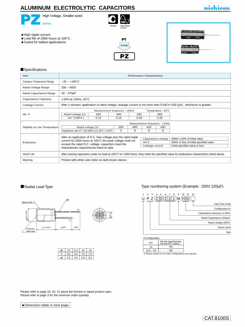
CAT.8100S
PZ series
High Voltage, Smaller-sized
High ripple current.Load life of 2000 hours at 105°C.Suited for ballast applications.
ALUMINUM ELECTROLYTIC CAPACITORS
U1
P2
Z3
24
D5
26
27
18
M9 10 11
Capacitance tolerance (± 20%)
Rated Capacitance (220µF)
Rated voltage (200V)
H D12
TCase Size Code
Series name
Type
φD
P
10
5.0
12.5
5.0
16
7.5
18
7.5
φd 0.6 0.8 0.8 0.8
Radial Lead Type Type numbering system (Example : 200V 220µF)
Configuration
P±0
.5
L+ 2.0 MAX 15MIN 4MIN
φD± 0
.5M
AX
Pressurerelief vent
Sleeve (P.E.T.)φ d
φ D
10
Pb free lead finishingPb free PET sleeve
PD
12.5 ~ 18 HD
Configuration
Please contact to us if other configurations are required.
Specifications
Category Temperature Range
Rated Voltage Range
Rated Capacitance Range
Capacitance Tolerance
Leakage Current
tan δ
Stability at Low Temperature
Endurance
Shelf Life
Marking
Performance CharacteristicsItem
–25 ~ +105°C
200 ~ 450V
18 ~ 470µF
±20% at 120Hz, 20°C
After 1 minutes' application of rated voltage, leakage current is not more than 0.04CV+100 (µA) , whichever is greater.
Printed with white color letter on dark brown sleeve.
After leaving capacitors under no load at 105°C for 1000 hours, they meet the specified value for endurance characteritics listed above.
Measurement frequency : 120Hz
Capacitance change
Leakage current
After an application of D.C. bias voltage plus the rated ripplecurrent for 2000 hours at 105°C the peak voltage shall notexceed the rated D.C. voltage, capacitors meet thecharacteristic requirements listed at right.
tan δWithin ±20% of initial value
Initial specified value or less200% or less of initial specified value
Z–25°C / Z+20°CRated voltage (V)
Impedance ratio ZT / Z20 (MAX.)2003
4008
4208
4508
Measurement frequency : 120Hz, Temperature : 20°C
Rated voltage (V)tan δ (MAX.)
2000.12
4200.20
4500.20
4000.15
Dimension table in next page.
Please refer to page 19, 20, 21 about the formed or taped product spec.Please refer to page 3 for the minimum order quantity.
PZ
PT
Smaller

CAT.8100S
Case size
Dimensions
18
22
27
33
39
47
56
68
82
100
120
150
180
220
270
330
390
470
180
220
270
330
390
470
560
680
820
101
121
151
181
221
271
331
391
471
.010 × 31.5
12.5 × 31.5
12.5 × 35.5
12.5 × 40.0
.016 × 31.5
.016 × 35.5
.018 × 31.5
.016 × 40.0
.018 × 35.5
.018 × 40.0
.010 × 31.5
12.5 × 31.5
12.5 × 35.5
12.5 × 40.0
.016 × 31.5
.016 × 35.5
.018 × 31.5
.016 × 40.0
.018 × 35.5
.018 × 40.0
.010 × 31.5
12.5 × 31.5
12.5 × 35.5
12.5 × 40.0
.016 × 31.5
.016 × 35.5
.016 × 40.0
.018 × 31.5
.018 × 35.5
.018 × 40.0
400
620
700
800
870
1010
1010
1130
1120
1270
240
370
420
480
580
670
670
770
770
880
2D 2G W6
200 400 420V
CodeCap.(µF)
ALUMINUM ELECTROLYTIC CAPACITORS
D × L (mm)
.010 × 31.5
12.5 × 31.5
12.5 × 35.5
12.5 × 40.0
.016 × 31.5
.016 × 35.5
.016 × 40.0
.018 × 31.5
.018 × 35.5
.018 × 40.0
Rated Ripple (mA rms) at 105°C 120Hz
200
310
360
430
510
570
610
610
660
710
180
280
320
380
440
490
550
550
650
740
2W
450
: In this case, 6 will be put at 12th digit of type numbering system.
PZ series
Frequency coefficient of rated voltageV
200
400 ~ 450
60Hz
0.80
0.80
120Hz
1.00
1.00
500Hz
1.20
1.25
1kHz
1.30
1.40
10kHz~
1.40
1.50

CAT.8100S
ALUMINUM ELECTROLYTIC CAPACITORS
RS series
Compact & Low-profile Sized
More compact & low profile case sizes than VS series.
Radial Lead Type
Specifications
Type numbering system (Example : 10V 330µF)
Category Temperature Range
Rated Voltage Range
Rated Capacitance Range
Capacitance Tolerance
Leakage Current
tan δ
Stability at Low Temperature
Endurance
Shelf Life
Marking
Performance CharacteristicsItem
–40 ~ +85˚C
6.3 ~ 400V
0.1 ~ 10000µF
±20% at 120Hz, 20˚C
Printed with white color letter on black sleeve.
After leaving capacitors under no load at 85˚C for 1000 hours, they meet the specifiedvalue for endurance characteristics listed above.
Rated voltage (V) 6.3 ~ 100 160 ~ 400
After 1 minute's application of rated voltage, leakage currentis not more than 0.03CV or 4 (µA), whichever is greater.
After 2 minutes' application of rated voltage, leakage currentis not more than 0.01CV or 3 (µA), whichever is greater.
After 1 minute's application of rated voltage.I = 0.04CV+100 (µA) or less
Rated voltage (V)tan δ (MAX.)
6.30.28
100.24
160.20
250.16
350.14
50 63 100 1600.12 0.10 0.08 0.20
200 2500.20 0.20
4000.25
For capacitance of more than 1000µF, add 0.02 for every increase of 1000µF. Measurement frequency : 120Hz, Temperature : 20˚C
Measurement frequency : 120Hz
After 2000 hours' application of rated voltage at 85˚C, capacitors meet the characteristic requirements listed at right.
Z–25˚C / Z+20˚C
Z–40˚C / Z+20˚C
Rated voltage (V)
Impedance ratioZT / Z20 (MAX.)
6.3512
10410
1638
2525
3524
5023
U1
R2
S3
14
A5
36
37
18
M9
N10
D11 12
ConfigurationCase size
Capacitance tolerance (±20%)
Rated Capacitance (330µF)
Rated voltage (10V)
Series name
Type
Pressurerelief vent
15MIN 4MIN
φd
φD+
0.5
MA
X
P±0
.5
(φ8up) L+ MAX
φ D
5 · 6.3
Pb free lead finishingPb free PET sleeve
Sn-Pb lead finishingPVC sleeve contain Pb
CD CA
8, 10 × 9 ND NA
10 × 12.5 PD PA
12.5 ~ 18 HD HA
20 RD RA
Configuration
Sleeve (P.E.T.)
Please contact to us if other configurations are required.
φDPφd
52.00.5
6.32.50.5
83.50.6
105.00.6
12.55.00.6
167.50.8
187.50.8
2010.01.0
(φD 20) 1.5(φD 20) 2.0
Leakage current
tan δCapacitance change
Initial specified value or less200% or less of initial specified valueWithin ±20% of initial value
Please refer to page 19, 20, 21 about the formed or taped product spec.Please refer to page 3 for the minimum order quantity.
RS
RZ
HighTemperature
(Through 100V only)
Dimension table in next page.
6323
10023
16034
20034
25036
400610

CAT.8100S
RS series
ALUMINUM ELECTROLYTIC CAPACITORS
Dimensions
0.1
0.22
0.33
0.47
1
2.2
3.3
4.7
10
22
33
47
100
220
330
470
1000
2200
3300
4700
6800
10000
0R1
R22
R33
R47
010
2R2
3R3
4R7
100
220
330
470
101
221
331
471
102
222
332
472
682
103
0J
6.3
1H
50
5 × 95 × 95 × 95 × 9
6.3 × 96.3 × 9
8 × 910 × 9
12.5 × 15
16 × 15
16 × 15
18 × 15
18 × 20
35
55
75
125
200
250
330
510
890
1200
1410
1660
2020
1.1
2.3
3.5
5
13
26
35
40
65
90
120
140
240
420
530
750
1160
1750
D × L (mm)
1V
35
5 × 95 × 95 × 95 × 9
6.3 × 98 × 9
10 × 910 × 12.5
12.5 × 12.5
16 × 15
18 × 20
20 × 25
35
55
95
100
130
220
340
480
590
1010
1560
2000
1E
25
5 × 95 × 95 × 95 × 95 × 9
6.3 × 910 × 910 × 910 × 12.5
12.5 × 15
18 × 15
18 × 20
18 × 25
30
50
75
95
110
180
310
380
530
830
1360
1720
2050
1C
16
5 × 95 × 95 × 95 × 9
6.3 × 98 × 9
10 × 910 × 9
12.5 × 12.5
16 × 15
18 × 15
18 × 20
18 × 25
40
70
85
100
160
290
360
410
720
1160
1460
1770
2170
1A
10
5 × 95 × 95 × 95 × 9
6.3 × 98 × 98 × 9
10 × 12.5
12.5 × 15
16 × 15
18 × 15
18 × 20
18 × 25
55
75
90
135
220
300
360
620
960
1300
1550
1850
2350
5 × 95 × 95 × 95 × 95 × 95 × 95 × 95 × 95 × 95 × 9
6.3 × 96.3 × 910 × 910 × 12.5
12.5 × 12.5
16 × 15
18 × 20
20 × 25
Case size
Frequency coefficient of rated ripple current
00 ~ 47100 ~ 470
1000 ~ 0000010 ~ 220
6.3 ~ 100
160 ~ 400
V 50Hz 120Hz 300Hz 1 kHz 10kHz ~0.75 1.00 1.35 1.57 2.000.80 1.00 1.23 1.34 1.500.85 1.00 1.10 1.13 1.150.80 1.00 1.25 1.40 1.60
0.1
0.22
0.33
0.47
1
2.2
3.3
4.7
10
22
33
47
68
100
150
220
330
470
0R1
R22
R33
R47
010
2R2
3R3
4R7
100
220
330
470
680
101
151
221
331
471
2C
160
16 × 15
• 18 × 15
∆ 18 × 20
18 × 25
.20 × 25
420
490
590
710
770
2G
400
16 × 15
•18 × 15
18 × 20
18 × 25
20 × 25
Case size
140
280
350
420
490
2E
250
.16 × 15
•18 × 15
.∆ 18 × 20
.18 × 20
.18 × 25
280
350
420
490
590
2D
200
.16 × 15
•18 × 15
∆ 18 × 20
18 × 25
.18 × 25
350
420
490
590
710
V
CodeCap.(µF)
Ratedripple
Ratedripple
Rated Ripple (mA rms) at 85˚C 120Hz
Size 16 × 20 is available for capacitors marked" •"Size 20 × 15 is available for capacitors marked" ∆ "Size 20 × 20 is available for capacitors marked " "
In this case, 6 will be put at 12th digit oftype numbering system.
V
CodeCap.(µF)
FrequencyCap.(µF)
2A
100
5 × 95 × 95 × 95 × 95 × 95 × 95 × 9
6.3 × 96.3 × 9
8 × 910 × 910 × 12.5
12.5 × 15
16 × 15
18 × 15
1.9
4.5
6.5
8
17
26
35
45
70
130
180
230
370
620
760
1J
63
5 × 9.51
6.3 × 9.51
8 × 9.51
8 × 9.51
10 × 9.51
12.5 × 12.5
12.5 × 15.5
16 × 15.5
60
100
140
170
250
490
710
900
Wider range of rating.

CAT.8100S
φDPφd
12.55.00.6
167.50.8
187.50.8
20101.0
22101.0
2512.51.0
U1
R2
U3
14
A5
26
27
28
M9
H10
D11
Configuration
Capacitance tolerance (±20%)
Rated Capacitance (2200µF)
Rated voltage (10V)
Series name
Type
(φD < 20) 1.5(φD 20) 2.0
Pressurerelief vent
15MIN 4MIN
Sleeve (P.E.T.) φd
φD+
0.5
MA
X
P±0
.5
L+ MAX
φ D
12.5 ~ 18
Pb free lead finishingPb free PET sleeve
HD
20 ~ 25 RD
Configuration
Please contact to us if other configurations are required.
RU
RY
ALUMINUM ELECTROLYTIC CAPACITORS
RU series
12.5mmL MAX.
12.5mmL MAX. height.
Specifications
Category Temperature Range
Rated Voltage Range
Rated Capacitance Range
Capacitance Tolerance
Leakage Current
tan δ
Stability at Low Temperature
Endurance
Shelf Life
Marking
Performance CharacteristicsItem
– 40 ~ + 85°C (6.3V ~ 400V), – 25 ~ + 85°C (450V)
6.3 ~ 450V
6.8 ~ 6800µF
±20% at 120Hz, 20°C
Printed with white color letter on black sleeve.
After leaving capacitors under no load at 85°C for 1000 hours, they meet the specified value forendurance characteristics listed above.
Rated voltage (V)tan δ (MAX.)
6.30.28
100.24
160.20
250.16
350.14
500.12
630.12
1000.12
160 ~ 3500.20
400 ~ 4500.25
For capacitance of more than 1000µF, add 0.02 for every increase of 1000µF. Measurement frequency : 120Hz, Temperature : 20°C
Measurement frequency : 120Hz
Z–25°C / Z+20°C
Z–40°C / Z+20°C
Rated voltage (V)
Impedance ratioZT / Z20 (MAX)
6.3512
10410
1638
2525
3524
160 ~ 20034
50 ~ 10023
250 ~ 35048
400610
45015—
After 2000 hours' application of rated voltage at 85°C,capacitors meet the characteristic requirements listed at right.
Rated voltage (V) 6.3 ~ 100V 160 ~ 450VAfter 1 minute's application of rated voltage, leakage current is not more than 0.03CV or 4 (µA), whichever is greater.
After 2 minutes' application of rated voltage, leakage current is not more than 0.01CV or 3 (µA), whichever is greater.
After 1 minute's application of rated voltage,I = 0.04CV+100 (µA) or less
Leakage current
tan δCapacitance change
Initial specified value or less200% or less of initial specified valueWithin ±20% of initial value
Please refer to page 19, 20, 21 about the formed or taped product spec.Please refer to page 3 for the minimum order quantity.
Radial Lead Type Type numbering system (Example : 10V 2200µF)
HighTem perature
Dimension table in next page.

CAT.8100S
330470680
10002200330047006800
331471681102222332472682
0J
6.31H
50
16 × 12.520 × 12.525 × 12.5
80014601600
530600750930
Rated
ripple
1V
35
12.5 × 12.518 × 12.5
720850
1E
25
12.5 × 12.525 × 12.5
7501380
1C
16
20 × 12.525 × 12.5
12001410
1A
10
12.5 × 12.518 × 12.525 × 12.5
87011001480
12.5 × 12.516 × 12.520 × 12.525 × 12.5
Case size
06.8100.220.330.470.
6R8100220330470
2V
350
12.5 × 12.518 × 12.520 × 12.525 × 12.5
110230230280
2W
450
12.5 × 12.516 × 12.522 × 12.5
7080
160
2G
400
16 × 12.520 × 12.525 × 12.5
110230280
Cap.(µF)
100 ~ 6801000 ~ 6800
6.8 ~ 100
6.3 ~ 100
V
160 ~ 450
50Hz 120Hz 300Hz 1 kHz 10kHz ~0.80 1.00 1.23 1.34 1.500.85 1.00 1.10 1.13 1.150.80 1.00 1.25 1.40 1.60
Frequency
22334768
100220330470680
220330470680101221331471681
1J
632F
315
12.5 × 12.518 × 12.522 × 12.525 × 12.5
490710900
1200
190230280
D × L (mm)
2E
250
16 × 12.518 × 12.520 × 12.525 × 12.5
190230280330
2D
200
12.5 × 12.516 × 12.518 × 12.522 × 12.525 × 12.5
190230280330380
2C
160
12.5 × 12.516 × 12.518 × 12.522 × 12.5
230280330380
2A
100
12.5 × 12.522 × 12.525 × 12.5
330620760
16 × 12.520 × 12.525 × 12.5
Rated Ripple (mA rms) at 85°C 120Hz
D × L (mm)
RU series
ALUMINUM ELECTROLYTIC CAPACITORS
Dimensions D × L (mm)
Frequency coefficient of rated ripple current
V
CodeCap.(µF)
V
CodeCap.(µF)
V
CodeCap.(µF)
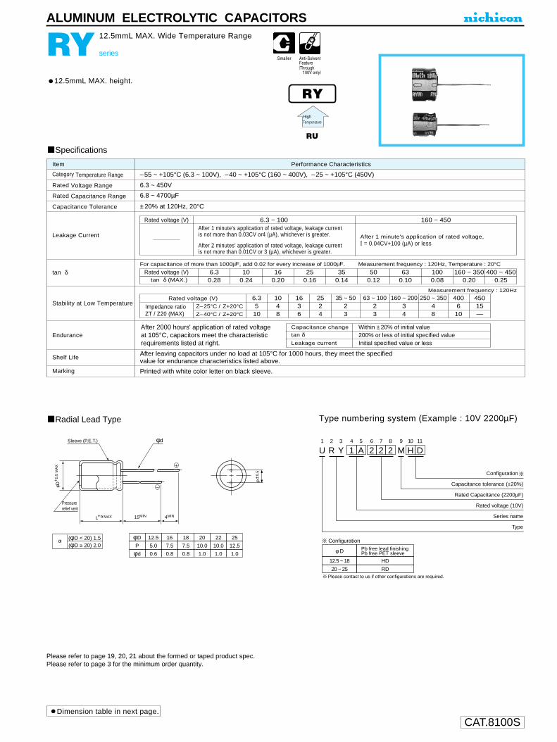
CAT.8100S
φD
P
φd
12.5
5.0
0.6
16
7.5
0.8
18
7.5
0.8
20
10.0
1.0
22
10.0
1.0
25
12.5
1.0
U1
R2
Y3
14
A5
26
27
28
M9
H10
D11
Configuration
Capacitance tolerance (±20%)
Rated Capacitance (2200µF)
Rated voltage (10V)
Series name
Type
(φD < 20) 1.5(φD 20) 2.0
Pressurerelief vent
15MIN 4MIN
Sleeve (P.E.T.) φd
φD+
0.5
MA
X
P±0
.5
L+ MAX
φ D
12.5 ~ 18
Pb free lead finishingPb free PET sleeve
HD
20 ~ 25 RD
Configuration
Please contact to us if other configurations are required.
RY
RU
ALUMINUM ELECTROLYTIC CAPACITORS
RY series
12.5mmL MAX. Wide Temperature Range
Radial Lead Type
Specifications
Type numbering system (Example : 10V 2200µF)
Category Temperature Range
Rated Voltage Range
Rated Capacitance Range
Capacitance Tolerance
Leakage Current
tan δ
Stability at Low Temperature
Endurance
Shelf Life
Marking
Performance CharacteristicsItem
–55 ~ +105°C (6.3 ~ 100V), –40 ~ +105°C (160 ~ 400V), –25 ~ +105°C (450V)
6.3 ~ 450V
6.8 ~ 4700µF
±20% at 120Hz, 20°C
Printed with white color letter on black sleeve.
After leaving capacitors under no load at 105°C for 1000 hours, they meet the specifiedvalue for endurance characteristics listed above.
Rated voltage (V) 6.3 ~ 100 160 ~ 450After 1 minute's application of rated voltage, leakage currentis not more than 0.03CV or4 (µA), whichever is greater.
After 2 minutes' application of rated voltage, leakage currentis not more than 0.01CV or 3 (µA), whichever is greater.
After 1 minute's application of rated voltage,I = 0.04CV+100 (µA) or less
Measurement frequency : 120Hz
Z–25°C / Z+20°C
Z–40°C / Z+20°C
Rated voltage (V)
Impedance ratioZT / Z20 (MAX)
6.3510
1048
1636
2524
160 ~ 20034
35 ~ 5023
63 ~ 10023
250 ~ 35048
400610
45015—
After 2000 hours' application of rated voltage at 105°C, capacitors meet the characteristic requirements listed at right.
Rated voltage (V)tan δ (MAX.)
6.30.28
100.24
160.20
250.16
350.14
500.12
630.10
1000.08
160 ~ 3500.20
400 ~ 4500.25
For capacitance of more than 1000µF, add 0.02 for every increase of 1000µF. Measurement frequency : 120Hz, Temperature : 20°C
Leakage current
tan δCapacitance change
Initial specified value or less200% or less of initial specified valueWithin ±20% of initial value
Please refer to page 19, 20, 21 about the formed or taped product spec.Please refer to page 3 for the minimum order quantity.
12.5mmL MAX. height.
HighTemperature
Dimension table in next page.

CAT.8100S
330470680
1000220033004700
331471681102222332472
0J
6.31H
50
12.5 × 12.518 × 12.525 × 12.5
580730
1200
1V
35
12.5 × 12.518 × 12.522 × 12.5
420610810
450540700
Rated
ripple
1E
25
12.5 × 12.518 × 12.525 × 12.5
500
770
1170
1C
16
12.5 × 12.525 × 12.5
5201000
1A
10
18 × 12.522 × 12.5
8201030
12.5 × 12.520 × 12.525 × 12.5
Case size
6.8102233
6R8100220330
2V
350
16 × 12.518 × 12.525 × 12.5
7590
140
2W
450
12.5 × 12.516 × 12.525 × 12.5
384785
2G
400
16 × 12.520 × 12.525 × 12.5
65150200
1022334768
100220330470
100220330470680101221331471
1J
632F
315
12.5 × 12.518 × 12.522 × 12.5
400550610
D × L (mm)
D × L (mm)
2E
250
16 × 12.518 × 12.522 × 12.5
130170190
7085120160
2D
200
12.5 × 12.516 × 12.518 × 12.525 × 12.5
110170230310
2C
160
12.5 × 12.516 × 12.520 × 12.525 × 12.5
130210280360
2A
100
12.5 × 12.522 × 12.5
230400
12.5 × 12.516 × 12.520 × 12.525 × 12.5
Rated Ripple (mA rms) at 105°C 120Hz
RY series
ALUMINUM ELECTROLYTIC CAPACITORS
Dimensions D × L (mm)V
Code
Code
Code
Cap.(µF)
V
Cap.(µF)
V
Cap.(µF)
Cap.(µF)
100 ~ 6801000 ~ 4700
6.8 ~ 100
6.3 ~ 100
V
160 ~ 450
50Hz 120Hz 300Hz 1 kHz 10kHz ~0.80 1.00 1.23 1.34 1.500.85 1.00 1.10 1.13 1.150.80 1.00 1.25 1.40 1.60
Frequency
Frequency coefficient of rated ripple current

CAT.8100S
Radial Lead Type
Specifications
Type numbering system (Example : 10V 330µF)
Category Temperature Range
Rated Voltage Range
Rated Capacitance Range
Capacitance Tolerance
Leakage Current
tan δ
Stability at Low Temperature
Endurance
Shelf Life
Marking
Performance CharacteristicsItem
–55 ~ +105˚C (6.3 ~ 100V) , –40 ~ +105˚C (160 ~ 400V)
6.3 ~ 400V
0.1 ~ 10000µF
±20% at 120Hz, 20˚C
Printed with white color letter on black sleeve.
After leaving capacitors under no load at 105˚C for 1000 hours, they meet the specifiedvalue for endurance characteristics listed above.
Rated voltage (V) 6.3 ~ 100 160 ~ 400
After 1 minute's application of rated voltage, leakage currentis not more than 0.03CV or 4 (µA), whichever is greater.
After 2 minutes' application of rated voltage, leakage currentis not more than 0.01CV or 3 (µA), whichever is greater.
After 1 minute's application of rated voltage,I = 0.04CV+100 (µA) or less
For capacitance of more than 1000µF, add 0.02 for every increase of 1000µF. Measurement frequency : 120Hz, Temperature : 20˚C
After 1000 hours' application of rated voltage at 105˚C, capacitors meet the characteristic requirements listed at right.
Measurement frequency : 120Hz
RZ
RS
U1
R2
Z3
14
A5
36
37
18
M9
N10
D11 12
Configuration
Case size
Capacitance tolerance (±20%)
Rated Capacitance (330µF)
Rated voltage (10V)
Series name
Type
Pressurerelief vent
15MIN 4MIN
φd
φD+
0.5
MA
X
P±0
.5
(φ8up) L+ MAX
φD
P
φd
5
2.0
0.5
6.3
2.5
0.5
8
3.5
0.6
10
5.0
0.6
12.5
5.0
0.6
16
7.5
0.8
18
7.5
0.8
20
10.0
1.0
(φD < 20) 1.5(φD 20) 2.0
Sleeve (P.E.T.)
φ D
5 · 6.3
Pb free lead finishingPb free PET sleeve
Sn-Pb lead finishingPVC sleeve contain Pb
CD CH
8 · 10 × 9 ND NH
10 × 12.5 PD PH
12.5 ~ 18 HD HH
20 RD RH
Configuration
Please contact to us if other configurations are required.
HighTemperature
Leakage current
tan δCapacitance change
Initial specified value or less200% or less of initial specified valueWithin ±20% of initial value
Please refer to page 19, 20, 21 about the formed or taped product spec.Please refer to page 3 for the minimum order quantity.
Dimension table in next page.
Rated voltage (V)tan δ (MAX.)
6.30.28
100.24
160.20
250.16
350.14
50 63 100 1600.12 0.10 0.08 0.20
200 2500.20 0.20
4000.25
Z–25˚C / Z+20˚C
Z–40˚C / Z+20˚C
Rated voltage (V)
Impedance ratioZT / Z20 (MAX.)
6.3510
1048
1636
2524
3523
5023
6323
10023
16034
20034
25036
400610
ALUMINUM ELECTROLYTIC CAPACITORS
RZ series
Compact & Low-Profile Sized, Wide Temperature Range
Very small case sizes same as RS series, but operating over widetemperature range of –55 (–40) ~ +105˚C. (Through 100V only)

CAT.8100S
RZ series
ALUMINUM ELECTROLYTIC CAPACITORS
Dimensions
0.1
0.22
0.33
0.47
1
2.2
3.3
4.7
10
22
33
47
100
220
330
470
1000
2200
3300
4700
6800
10000
0R1
R22
R33
R47
010
2R2
3R3
4R7
100
220
330
470
101
221
331
471
102
222
332
472
682
103
0J
6.3
1H
50
5 × 95 × 95 × 95 × 9
6.3 × 96.3 × 9
8 × 910 × 9
12.5 × 15
16 × 15
16 × 15
18 × 15
18 × 20
25
40
55
90
145
180
235
370
635
860
1010
1200
1450
1V
35
5 × 95 × 95 × 95 × 9
6.3 × 98 × 9
10 × 910 × 12.5
12.5 × 12.5
16 × 15
18 × 20
20 × 25
25
40
60
75
95
155
235
340
420
720
1110
1430
1.1
2.3
3.5
5
12
18
25
30
46
65
85
100
170
290
370
540
830
1250
1E
25
5 × 95 × 95 × 95 × 95 × 9
6.3 × 9...
10 × 9..
10 × 9..
...10 × 12.5
12.5 × 15...
18 × 15
18 × 20
18 × 25
20
35
55
70
80
130
220
270
370
590
970
1220
1470
1C
16
5 × 95 × 95 × 95 × 9
6.3 × 9...
8 × 9..
10 × 9..
10 × 9..
.12.5 × 12.5.
16 × 15
18 × 15
18 × 20
18 × 25
30
50
60
70
115
205
240
290
520
830
1050
1260
1560
1A
10
5 × 95 × 95 × 95 × 9
6.3 × 98 × 98 × 9
10 × 12.5
12.5 × 15
16 × 15
18 × 15
18 × 20
18 × 25
40
55
65
95
155
210
275
450
690
940
1120
1330
1700
5 × 95 × 95 × 95 × 95 × 95 × 95 × 95 × 95 × 95 × 9
6.3 × 96.3 × 910 × 910 × 12.5
12.5 × 12.5
16 × 15
18 × 20
20 × 25
Case size
100 ~ 470100 ~ 470
1000 ~00000010 ~ 220
6.3 ~ 100
V
160 ~ 400
50Hz 120Hz 300Hz 1 kHz 10kHz ~0.75 1.00 1.35 1.57 2.000.80 1.00 1.23 1.34 1.500.85 1.00 1.10 1.13 1.150.80 1.00 1.25 1.40 1.60
V
CodeCap.(µF)
D × L (mm)
Rated Ripple (mA rms) at 105˚C 120Hz
Size 16 × 20 is available for capacitors marked " • "Size 20 × 15 is available for capacitors marked " ∆ "Size 20 × 20 is available for capacitors marked " "
In this case, 6 will be put at 12th digit oftype numbering system.
Frequency coefficient of rated ripple currentFrequency
Cap.(µF)
Ratedripple
0.1
0.22
0.33
0.47
1
2.2
3.3
4.7
10
22
33
47
68
100
150
220
330
470
0R1
R22
R33
R47
010
2R2
3R3
4R7
100
220
330
470
680
101
151
221
331
471
2C
160
16 × 15
•18 × 15
∆ 18 × 20
18 × 25
.20 × 25
300
350
420
510
550
2G
400
16 × 15
•18 × 15
18 × 20
18 × 25
20 × 25
Case size
100
200
250
300
350
2E
250
.16 × 15
•18 × 15
.∆ 18 × 20
.18 × 20
.18 × 25
200
250
300
350
420
2D
200
.16 × 15
•18 × 15
∆ 18 × 20
18 × 25
.18 × 25
250
300
350
420
510
Ratedripple
V
CodeCap.(µF) 2A
100
5 × 95 × 95 × 95 × 95 × 95 × 95 × 9
6.3 × 96.3 × 9
8 × 910 × 9
10 × 12.5
12.5 × 15
16 × 15
18 × 15
1.2
3
4.5
6.5
12
17
25
32
50
93
130
165
265
440
540
1J
63
5 × 9.51
6.3 × 9.51
8 × 9.51
8 × 9.51
10 × 9.51
12.5 × 12.5
12.5 × 15.5
16 × 15.5
42
71
100
120
215
335
510
640
Wider range of rating.
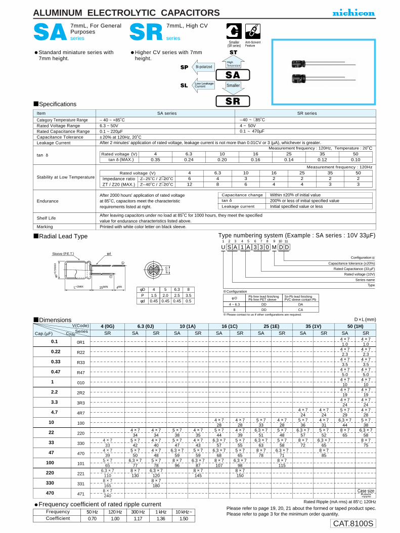
CAT.8100S
4 × 733
4 × 739
5 × 765
6.3 × 71108 × 71658 × 7240
L+1MAX 15MIN 4MIN
φD+
0.5
MA
X
P±0.
5
φd
φD
Pφd
4
1.50.45
5
2.00.45
6.3
2.50.45
8
3.50.5
Sleeve (P.E.T.)
U1
S2
A3
14
A5
36
37
08
M9
D10
D11
Configuration
Capacitance tolerance (±20%)
Rated Capacitance (33 µF)
Rated voltage (10V)
Series name
Type
φ D
4 ~ 6.3
Pb free lead finishingPb free PET sleeve
Sn-Pb lead finishingPVC sleeve contain Pb
DD DA
8 DD CA
Configuration
Please contact to us if other configurations are required.
ALUMINUM ELECTROLYTIC CAPACITORS
SA series
7mmL, For GeneralPurposes
Standard miniature series with7mm height.
SR series
7mmL, High CV
Higher CV series with 7mmheight.
Radial Lead Type
Specifications
Category Temperature RangeRated Voltage RangeRated Capacitance RangeCapacitance ToleranceLeakage Current
tan δ
Stability at Low Temperature
Endurance
Shelf Life
Marking
SA series SR seriesItem
– 40 ~ +85˚C –40 ~ +85˚C6.3 ~ 50V 4 ~ 50V0.1 ~ 220µF 0.1 ~ 470µF±20% at 120Hz, 20˚CAfter 2 minutes' application of rated voltage, leakage current is not more than 0.01CV or 3 (µA), whichever is greater.
Printed with white color letter on black sleeve.
Measurement frequency : 120Hz, Temperature : 20˚C
Measurement frequency : 120Hz
After 2000 hours' application of rated voltage at 85˚C, capacitors meet the characteristic requirements listed at right.
After leaving capacitors under no load at 85˚C for 1000 hours, they meet the specifiedvalue for endurance characteristics listed above.
Rated voltage (V)tan δ (MAX.)
500.10
350.12
250.14
160.16
100.20
6.30.24
40.35
Z–25˚C / Z+20˚C
Z–40˚C / Z+20˚C
Rated voltage (V)
Impedance ratioZT / Z20 (MAX.)
5023
3523
2524
1624
1036
6.348
4612
Dimensions
0.1
0.22
0.33
0.47
1
2.2
3.3
4.7
10
22
33
47
100
220
330
470
0R1
R22
R33
R47
010
2R2
3R3
4R7
100
220
330
470
101
221
331
471
D ×L(mm)V(Code)
CodeCap.(µF)4 × 71.0
4 × 72.3
4 × 73.5
4 × 75.0
4 × 710
4 × 719
4 × 724
4 × 728
5 × 738
6.3 × 758
8 × 775
4 × 71.0
4 × 72.3
4 × 73.5
4 × 75.0
4 × 710
4 × 719
4 × 724
5 × 729
6.3 × 744
8 × 765
4 × 724
4 × 731
5 × 752
6.3 × 765
8 × 785
4 × 724
5 × 736
6.3 × 757
8 × 772
4 × 728
5 × 748
5 × 758
6.3 × 771
8 × 7115
5 × 733
6.3 × 751
6.3 × 763
8 × 778
4 × 728
4 × 739
5 × 755
5 × 765
6.3 × 798
8 × 7150
4 × 728
5 × 744
6.3 × 757
6.3 × 768
8 × 7107
4 × 735
4 × 743
5 × 759
6.3 × 787
8 × 7145
5 × 738
5 × 747
6.3 × 759
8 × 796
4 × 734
4 × 740
4 × 748
5 × 778
6.3 × 71208 × 7180
4 × 734
5 × 742
5 × 750
6.3 × 777
8 × 7130
50 (1H)SRSA
Case size
Rated Ripple (mA rms) at 85˚C 120Hz
Type numbering system (Example : SA series : 10V 33µF)
SA
SR
Bi-polarizedSP
Low LeakageCurrentSL Smaller
Series35 (1V)
SRSA
25 (1E)SRSA
16 (1C)SRSA
10 (1A)SRSA
6.3 (0J)4 (0G)SRSR SA
Ratedripple
HighTemperature
Capacitance change
Leakage current
tan δWithin ±20% of initial value
Initial specified value or less200% or less of initial specified value
Smaller(SR series)
ST
Please refer to page 19, 20, 21 about the formed or taped product spec.Please refer to page 3 for the minimum order quantity.
Frequency coefficient of rated ripple current
CoefficientFrequency 50 Hz 120 Hz 300 Hz 1 kHz 10 kHz~
0.70 1.00 1.17 1.36 1.50

CAT.8100S
U1
S2
F3
14
A5
36
37
08
M9
D10
D11
Configuration
Capacitance tolerance (±20%)
Rated Capacitance (33 µF)
Rated voltage (10V)
Series name
Type
φD
Pφd
41.50.45
83.50.5
52.00.45
6.32.50.45
P±0
.5
L+1MAX 15MIN 4MIN
φD+
0.5
MA
X
φd
φ D
4 ~ 6.3
Pb free lead finishingPb free PET sleeve
Sn-Pb lead finishingPVC sleeve contain Pb
DD DH
8 DD CH
Configuration
Sleeve (P.E.T.)
Please contact to us if other configurations are required.
ALUMINUM ELECTROLYTIC CAPACITORS
SF series
7mmL, Low Impedance
Low impedance over wide temperature range of –55~+105˚C, with 7mm height.
Radial Lead Type Type numbering system (Example : 10V 33µF)
Specifications
Category Temperature Range
Rated Voltage Range
Rated Capacitance Range
Capacitance Tolerance
Leakage Current
tan δ
Stability at Low Temperature
Endurance
Shelf Life
Marking
Performance CharacteristicsItem
–55 ~ +105˚C
6.3 ~ 35V
6.8 ~ 220µF
±20% at 120Hz, 20˚C
After 2 minutes' application of rated voltage, leakage current is not more than 0.01CV or 3(µA), whichever is greater.
Printed with white color letter on dark brown sleeve.
After 1000 hours' application of rated voltage at105˚C, capacitors meet the characteristicrequirements listed at right.
After leaving capacitors under no load at 105˚C for 1000 hours, they meet the specified value for endurance characteristics listed above.
SF ST
Dimensions D ×L (mm)
Case sizeImpe-dance
Ratedripple
Max. Impedance (Ω) at 20˚C 100kHzRated Ripple (mA rms) at 105˚C 100kHz
Measurement frequency : 120Hz, Temperature : 20˚C
Measurement frequency : 120Hz
Rated voltage (V)
tan δ (MAX.)6.30.18
100.16
160.14
250.12
350.12
Z–25˚C / Z+20˚C
Z–55˚C / Z+20˚C
Rated voltage (V)
Impedance ratioZT / Z20 (MAX.)
6.323
1023
1623
2523
3523
6.8101522334768
100150220
6R8100150220330470680101151221
0J
6.31A
101C
161E
251V
35
4 × 75 × 7
6.3 × 76.3 × 7
8 × 7
3.31.70.80.80.5
701101601602005 × 7
5 × 76.3 × 76.3 × 7
8 × 78 × 7
1.71.70.80.80.50.5
110110160160200200
4 × 75 × 7
6.3 × 76.3 × 7
8 × 78 × 7
3.31.70.80.80.50.5
70110160160200200
4 × 75 × 7
6.3 × 76.3 × 7
8 × 78 × 7
3.31.70.80.80.50.5
70110160160200200
4 × 75 × 75 × 7
6.3 × 78 × 78 × 7
3.31.71.70.80.50.5
70110110160200200
Cap.(µF) Code
V
LowImpedance
Leakage current
tan δCapacitance change Within ±20% of initial value
200% or less of initial specified valueInitial specified value or less
Please refer to page 19, 20, 21 about the formed or taped product spec.Please refer to page 3 for the minimum order quantity.
Frequency coefficient of rated ripple current
CoefficientFrequency 50 Hz 120 Hz 300 Hz 1 kHz 10 kHz ~
0.35 0.50 0.64 0.83 1.00
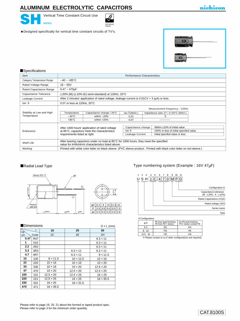
CAT.8100S
U1
S2
H3
14
C5
46
77
08
M9
P10
D11
Configuration
Capacitance tolerance (M : ±20%, K : ±10%)
Rated Capacitance (47µF)
Rated voltage (16V)
Series name
TypeL+1MAX 15MIN 4MIN
φd
φD+
0.5
MA
X
P±0
.5
φD
P
φd
6.3
2.5
0.5
8
3.5
0.6
10
5.0
0.6
12.5
5.0
0.6
16
7.5
0.8
Pressurerelief vent
Sleeve (P.E.T.)
φ D
6.3
Pb free lead finishingPb free PET sleeve
Sn-Pb lead finishingPVC sleeve contain Pb
ED EA
PA8 · 10 PD
12.5 · 16 HD HA
Configuration
Please contact to us if other configurations are required.
ALUMINUM ELECTROLYTIC CAPACITORS
SH series
Vertical Time Constant Circuit Use
Designed specifically for vertical time constant circuits of TV's.
Radial Lead Type
Dimensions
Type numbering system (Example : 16V 47µF)
Specifications
Category Temperature Range
Rated Voltage Range
Rated Capacitance Range
Capacitance Tolerance
Leakage Current
tan δ
Stability at Low and HighTemperature
Endurance
Shelf Life
Marking
Performance CharacteristicsItem
–40 ~ +85°C
16 ~ 50V
0.47 ~ 470µF
±20% (M) (±10% (K) semi-standard) at 120Hz, 20°C
After 2 minutes' application of rated voltage, leakage current is 0.01CV + 3 (µA) or less.
0.07 or less at 120Hz, 20°C
Printed with white color letter on black sleeve. (PVC sleeve product : Printed with black color letter on red sleeve.)
Measurement frequency : 120Hz
After 1000 hours' application of rated voltageat 85°C, capacitors meet the characteristicsrequirements listed at right.
After leaving capacitors under no load at 85°C for 1000 hours, they meet the specifiedvalue for endurance characteristics listed above.
D × L (mm)
Temperature
–40°C
+85°C
Capacitance change / 20°C
within –20%
within +20%
tan δ (MAX.)
0.21
0.07
Impedance ratio ZT / Z+20°C (MAX.)
2
Capacitance change
Leakage Current
tan δWithin ±10% of initial value150% or less of initial specified valueInitial specifed value or less
0.4712.23.34.7
10223347
100220330470
R470102R23R34R7100220330470101221331471
8 × 11.510 × 1610 × 1610 × 20
12.5 × 2012.5 × 25
16 × 2516 × 35.5
1CCap.(µF)
16
Code
6.3 × 116.3 × 1110 × 12.510 × 1610 × 20
12.5 × 2012.5 × 25
16 × 2516 × 31.5
1E
25
6.3 × 116.3 × 116.3 × 116.3 × 11
8 × 11.510 × 1610 × 20
12.5 × 2012.5 × 25
16 × 2516 × 35.5
1H
50V
Please refer to page 19, 20, 21 about the formed or taped product spec.Please refer to page 3 for the minimum order quantity.
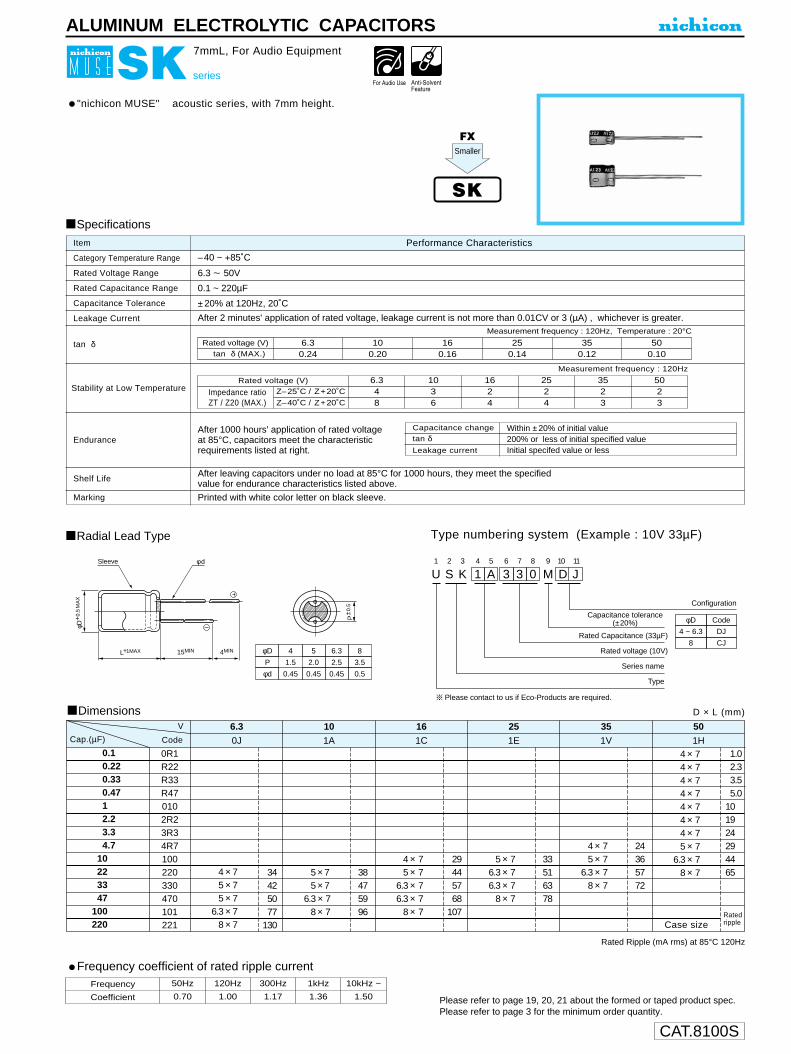
CAT.8100S
ALUMINUM ELECTROLYTIC CAPACITORS
U1
S2
K3
14
A5
36
37
08
M9
D10
J11
Configuration
Capacitance tolerance (±20%)
Rated Capacitance (33µF)
Rated voltage (10V)
Series name
Type
φD
4 ~ 6.3
Code
DJ
8 CJφD
P
φd
4
1.5
0.45
5
2.0
0.45
6.3
2.5
0.45
8
3.5
0.5
P±0
.5
L+1MAX 15MIN 4MIN
φD+
0.5
MA
X
Sleeve φ d
Please contact to us if Eco-Products are required.
SK series
7mmL, For Audio Equipment
"nichicon MUSE" acoustic series, with 7mm height.
Radial Lead Type Type numbering system (Example : 10V 33µF)
Specifications
Category Temperature Range
Rated Voltage Range
Rated Capacitance Range
Capacitance Tolerance
Leakage Current
tan δ
Stability at Low Temperature
Endurance
Shelf Life
Marking
Performance CharacteristicsItem
–40 ~ +85˚C
6.3 ~ 50V
0.1 ~ 220µF
±20% at 120Hz, 20˚C
After 2 minutes' application of rated voltage, leakage current is not more than 0.01CV or 3 (µA) , whichever is greater.
Printed with white color letter on black sleeve.
Measurement frequency : 120Hz
After 1000 hours' application of rated voltageat 85°C, capacitors meet the characteristicrequirements listed at right.
After leaving capacitors under no load at 85°C for 1000 hours, they meet the specifiedvalue for endurance characteristics listed above.
Rated voltage (V)tan δ (MAX.)
6.30.24
100.20
160.16
250.14
350.12
500.10
SK
Z–25˚C / Z+20˚C
Z–40˚C / Z+20˚C
Rated voltage (V)
Impedance ratioZT / Z20 (MAX.)
6.348
1036
1624
2524
3523
5023
Measurement frequency : 120Hz, Temperature : 20°C
Capacitance change
Leakage current
tan δWithin ±20% of initial value200% or less of initial specified valueInitial specifed value or less
FX
Dimensions
0.10.220.330.4712.23.34.7
10223347
100220
0R1R22R33R470102R23R34R7100220330470101221
4 × 75 × 75 × 7
6.3 × 78 × 7
34425077
130
0J
Rated Ripple (mA rms) at 85°C 120Hz
6.3
5 × 75 × 7
6.3 × 78 × 7
38475996
1A
10
4 × 75 × 7
6.3 × 76.3 × 7
8 × 7
29445768
107
1C
16
5 × 76.3 × 76.3 × 7
8 × 7
33516378
1E
25
4 × 75 × 7
6.3 × 78 × 7
24365772
1V
35
4 × 74 × 74 × 74 × 74 × 74 × 74 × 75 × 7
6.3 × 78 × 7
1.02.33.55.0
101924294465
1H
50
D × L (mm)
V
CodeCap.(µF)
Case sizeRatedripple
Smaller
Please refer to page 19, 20, 21 about the formed or taped product spec.Please refer to page 3 for the minimum order quantity.
Frequency coefficient of rated ripple currentFrequency
Coefficient
50Hz
0.70
120Hz
1.00
300Hz
1.17
1kHz
1.36
10kHz ~
1.50

CAT.8100S
P±0
.5
L+1MAX 15MIN 4MIN
φD+
0.5
MA
X
φd Sleeve (P.E.T.)
φDP
φd
41.5
0.45
83.5
0.5
52.0
0.45
6.32.5
0.45
ALUMINUM ELECTROLYTIC CAPACITORS
SL series
7mmL, Low Leakage Current
Low leakage current series with 7mm height.
Radial Lead Type
Dimensions
Type numbering system (Example : 10V 33µF)
U1
S2
L3
14
A5
36
37
08
M9
D10
D11
Configuration
Capacitance tolerance (±20%)
Rated Capacitance (33µF)
Rated voltage (10V)
Series name
Type
φ D
4 ~ 6.3
Pb free lead finishingPb free PET sleeve
Sn-Pb lead finishingPVC sleeve contain Pb
DD DA
8 DD CA
Configuration
Please contact to us if other configurations are required.
Specifications
Category Temperature Range
Rated Voltage Range
Rated Capacitance Range
Capacitance Tolerance
Leakage Current
tan δ
Stability at Low Temperature
Endurance
Shelf Life
Marking
Performance CharacteristicsItem
–40 ~ +85˚C
6.3 ~ 50V
0.1~ 220µF
±20% at 120Hz, 20˚C
After 2 minutes' application of rated voltage, leakage current is not more than 0.002CV or 0.4 (µA),whichever is greater.
Printed with white color letter on black sleeve. (PVC sleeve product : Printed with black color letter on yellow sleeve.
Measurement frequency : 120Hz, Temperature : 20˚C
Measurement frequency : 120Hz
After 1000 hours' application of rated voltage at 85˚C, capacitors meet the characteristic requirements listed at right.
After leaving capacitors under no load at 85˚C for 1000 hours, they meet the specified value for endurance characteristics listed above.
SL SA
Rated voltage (V)tan δ (MAX.)
6.30.24
100.20
160.16
250.14
350.12
500.10
Z–25˚C / Z+20˚C
Z–40˚C / Z+20˚C
Rated voltage (V)
Impedance ratioZT / Z20 (MAX.)
6.348
1036
1624
2524
3523
5023
D ×L (mm)
Rated Ripple (mA rms) at 85˚C 120Hz
0.10.220.330.4712.23.34.7
10223347
100220
0R1R22R33R470102R23R34R7100220330470101221
0.4 × 70.5 × 70.5 × 76.3 × 70.8 × 7
34425077
130
0J
6.31A
101C
161E
251V
351H
50
0.5 × 70.5 × 76.3 × 70.8 × 7
38475996
0.4 × 70.5 × 76.3 × 76.3 × 70.8 × 7
29445768
107
0.5 × 76.3 × 76.3 × 70.8 × 7
33516378
0.4 × 70.5 × 76.3 × 70.8 × 7
24365772
0.4 × 70.4 × 70.4 × 70.4 × 70.4 × 70.4 × 70.4 × 70.5 × 76.3 × 70.8 × 7
1.02.33.55.0
101924294465
V
CodeCap.(µF)
Case size
Low LeakageCurrent
Capacitance change
Leakage current
tan δWithin ±20% of initial value200% or less of initial specified valueInitial specified value or less
RatedRipple
Please refer to page 19, 20, 21 about the formed or taped product spec.Please refer to page 3 for the minimum order quantity.
Frequency coefficient of rated ripple current
CoefficientFrequency 50 Hz 120 Hz 300 Hz 1 kHz 10 kHz~
0.70 1.00 1.17 1.36 1.50

CAT.8100S
φD
Pφd
4
1.50.45
5
2.00.45
6.3
2.50.45
8
3.50.5
P±0
.5
L+1MAX 15MIN 4MIN
φD+
0.5
MA
X
φd Sleeve (P.E.T.) U1
S2
P3
14
A5
36
37
08
M9
D10
D11
Configuration
Capacitance tolerance (±20%)
Rated Capacitance (33µF)
Rated voltage (10V)
Series name
Type
φ D
4 ~ 6.3
Pb free lead finishingPb free PET sleeve
Sn-Pb lead finishingPVC sleeve contain Pb
DD DA
8 DD CA
Configuration
Please contact to us if other configurations are required.
ALUMINUM ELECTROLYTIC CAPACITORS
SP series
7mmL, Bi-Polarized
Bi-polarized series with 7mm height.Extended capacitance range by an addition of φ8 product.
Radial Lead Type
Dimensions
Type numbering system (Example : 10V 33µF)
Specifications
Category Temperature Range
Rated Voltage Range
Rated Capacitance Range
Capacitance Tolerance
Leakage Current
tan δ
Stability at Low Temperature
Endurance
Shelf Life
Marking
Performance CharacteristicsItem
–40 ~ +85˚C
6.3 ~ 50V
0.1 ~ 220µF
±20% at 120Hz, 20˚C
After 2 minutes' application of rated voltage, leakage current is not more than 0.05CV or 10 (µA), whichever is greater.
Printed with white color letter on black sleeve.
Measurement frequency : 120Hz, Temperature : 20˚C
Measurement frequency : 120 Hz
After 2000 hours' application of ratedvoltage at 85˚C with the polarity invertedevery 250 hours, capacitors meet thecharacteristic requirements listed at right.
After leaving capacitors under no load at 85˚C for 1000 hours, they meet the specified value for endurance characteristics listed above.
Rated voltage (V)tan δ (MAX.)
Z–25˚C / Z+20˚C
Z–40˚C / Z+20˚C
Rated voltage (V)
Impedance ratioZT / Z20 (MAX.)
500.12
350.14
250.16
160.16
100.20
6.30.24
6.348
1036
1624
2524
3523
5023
Rated Ripple (mA rms) at 85˚C 120Hz
SP Bi-polarized SA
D ×L(mm)
0.10.220.330.4712.23.34.7
10223347
100220
0R1R22R33R470102R23R34R7100220330470101221
0.5 × 76.3 × 70.8 × 70.8 × 7
425895
140
0J
6.3
0.4 × 70.5 × 76.3 × 76.3 × 70.8 × 7
24405667
110
1A
10
0.4 × 70.5 × 76.3 × 76.3 × 76.3 × 70.8 × 7
1830516375
125
1C
16
0.5 × 76.3 × 76.3 × 70.8 × 70.8 × 7
2135537387
1E
25
0.4 × 70.5 × 76.3 × 70.8 × 70.8 × 7
1622376276
1V
35
0.4 × 70.4 × 70.4 × 70.4 × 70.4 × 70.4 × 70.5 × 76.3 × 70.8 × 70.8 × 7
1.02.33.55.0
101420274465
1H
50
Case size
Cap.(µF) Code
V
Please refer to page 19, 20, 21 about the formed or taped product spec.Please refer to page 3 for the minimum order quantity.
Frequency coefficient of rated ripple current
CoefficientFrequency 50 Hz 120 Hz 300 Hz 1 kHz 10 kHz ~
0.70 1.00 1.17 1.36 1.50
Capacitance change
Leakage current
tan δWithin ±20% of initial value
Initial specified value or less200% or less of initial specified value
Ratedripple

CAT.8100S
2523
1624
1025
6.336
ST
φD
P
φd
4
1.5
0.45
5
2.0
0.45
6.3
2.5
0.45
8
3.5
0.5
P±0
.5
L+1MAX 15MIN 4MIN
φD+
0.5
MA
X
φd Sleeve (P.E.T.)
ALUMINUM ELECTROLYTIC CAPACITORS
ST series
7mmL, Wide Temperature Range
Wide temperature range of –55 ~ +105˚C, with 7mm height.
Radial Lead TypeType numbering system (Example : 10V 33µF)
U1
S2
T3
14
A5
36
37
08
M9
D10
D11
Configuration
Capacitance tolerance (±20%)
Rated Capacitance (33µF)
Rated voltage (10V)
Series name
Type
φ D
4 ~ 6.3
Pb free lead finishingPb free PET sleeve
Sn-Pb lead finishingPVC sleeve contain Pb
DD DH
8 DD CH
Configuration
Please contact to us if other configurations are required.
Specifications
Category Temperature Range
Rated Voltage Range
Rated Capacitance Range
Capacitance Tolerance
Leakage Current
tan δ
Stability at Low Temperature
Endurance
Shelf Life
Marking
Performance CharacteristicsItem
–55 ~ +105˚C
6.3 ~ 50V
0.1 ~ 220µF
±20% at 120Hz, 20˚C
After 2 minutes' application of rated voltage, leakage current is not more than 0.01CV or 3 (µA), whichever is greater.
Printed with white color letter on black sleeve.
Measurement frequency : 120Hz, Temperature : 20˚C
Measurement frequency : 120 Hz
After 1000 hours' application of ratedvoltage at 105˚C, capacitors meet thecharacteristic requirement listed at right.
After leaving capacitors under no load at 105˚C for 1000 hours, they meet the specified value for endurance characteristics listed above.
Rated voltage (V)tan δ (MAX.)
Z–25˚C / Z+20˚C
Z–40˚C / Z+20˚C
Rated voltage (V)
Impedance ratioZT / Z20 (MAX.)
6.30.24
100.21
160.18
250.15
350.13
500.12
3523
5023
Dimensions D ×L (mm)
Rated Ripple (mA rms) at 105˚C 120Hz
SA
0.10.220.330.4712.23.34.7
10223347
100220
0R1R22R33R470102R23R34R7100220330470101221
4 × 75 × 75 × 7
6.3 × 78 × 7
34425077
130
0J
V 6.31A10
1C16
1E25
1V35
1H50
5 × 75 × 7
6.3 × 78 × 7 8 × 7
4 × 75 × 7
6.3 × 76.3 × 7
8 × 7
5 × 76.3 × 76.3 × 7
8 × 7
4 × 75 × 7
6.3 × 78 × 7
4 × 74 × 74 × 74 × 74 × 74 × 74 × 75 × 7
6.3 × 78 × 738
475996
140
29445768
107
33516378
24365772
1.02.33.55.0
101924294465
Case sizeRatedripple
Cap.(µF) Code
HighTemperature
Leakage current
tan δ
Capacitance change Within ±25% of initial value (16Vor less)Within ±20% of initial value (5Vor more)200% or less of initial specified valueInitial specified value or less
Please refer to page 19, 20, 21 about the formed or taped product spec.Please refer to page 3 for the minimum order quantity.
Frequency coefficient of rated ripple current
CoefficientFrequency 50 Hz 120 Hz 300 Hz 1 kHz 10 kHz ~
0.70 1.00 1.17 1.36 1.50

CAT.8100S
U1
S2
V3
14
A5
36
37
08
M9
F10
D11
Configuration
Capacitance tolerance (±20%)
Rated Capacitance (33µF)
Rated voltage (10V)
Series name
Type
φ D
4 ~ 8
Pb free lead finishingPb free PET sleeve
Sn-Pb lead finishingPVC sleeve contain Pb
FD FH
Configuration
Please contact to us if other configurations are required.
φD
P
φd
4
1.5
0.45
8
3.5
0.5
5
2.0
0.45
6.3
2.5
0.45
L+1MAX 15MIN 4MIN
φd
φD+
0.5
MA
X
P±0
.5
Sleeve (P.E.T.)
ALUMINUM ELECTROLYTIC CAPACITORS
SV series
7mmL, Long Life Assurance
Extended load life of 5000 hours at +105˚C, with 7mm height.
Radial Lead Type
Dimensions
Type numbering system (Example: 10V 33µF)
Specifications
Category Temperature Range
Rated Voltage Range
Rated Capacitance Range
Capacitance Tolerance
Leakage Current
tan δ
Stability at Low Temperature
Endurance
Shelf Life
Marking
Performance CharacteristicsItem
–40 ~ +105˚C
6.3 ~ 50V
0.1~ 220µF
±20% at 120Hz, 20˚C
After 2 minutes' application of rated voltage, leakage current is not more than 0.01CV or 3(µA), whichever is greater.
Printed with silver color letter on dark brown sleeve.
Measurement frequency : 120Hz, Temperature : 20˚C
Measurement frequency : 120Hz
After 5000 hours' application of rated voltage at105˚C, capacitors meet the characteristicrequirements listed at right.
After leaving capacitors under no load at 105˚C for 1000 hours, they meet the specifiedvalue for endurance characteristics listed above.
SVLong LifeST
Rated voltage (V)tan δ (MAX.)
6.30.24
100.21
160.18
250.15
350.13
500.12
Z–25˚C / Z+20˚C
Z–40˚C / Z+20˚C
Rated voltage (V)
Impedance ratioZT / Z20 (MAX.)
6.348
1036
1624
2523
3523
5023
D ×L (mm)
Rated Ripple (mA rms) at 105˚C 120Hz
Case sizeRatedripple
0.10.220.330.4712.23.34.7
10223347
100220
0R1R22R33R470102R23R34R7100220330470101221
4 × 75 × 75 × 7
6.3 × 78 × 7
34425077
130
V
0J6.3
1A10
1C16
1E25
1V35
1H50
5 × 75 × 7
6.3 × 78 × 7
38475996
4 × 75 × 7
6.3 × 76.3 × 7
8 × 7
29445768
107
5 × 76.3 × 76.3 × 7
8 × 7
33516378
4 × 75 × 7
6.3 × 78 × 7
24365772
4 × 74 × 74 × 74 × 74 × 74 × 74 × 75 × 7
6.3 × 78 × 7
1.02.33.55.0
101924294465
Cap.(µF) Code
Leakage current
tan δCapacitance change Within ±30% of initial value
300% or less of initial specified valueInitial specified value or less
Please refer to page 19, 20, 21 about the formed or taped product spec.Please refer to page 3 for the minimum order quantity.
Frequency coefficient of rated ripple current
CoefficientFrequency 50 Hz 120 Hz 300 Hz 1 kHz 10 kHz ~
0.70 1.00 1.17 1.36 1.50

CAT.8100S
ALUMINUM ELECTROLYTIC CAPACITORS
U1
S2
W3
14
A5
36
37
08
M9
D10
A11
Configuration
Capacitance tolerance (±20%)
Rated Capacitance (33µF)
Rated voltage (10V)
Series name
Type
φD
4 ~ 6.3
Code
DA
φD
P
φd
4
1.5
0.45
5
2.0
0.45
6.3
2.5
0.45
P±0
.5
L+1MAX 15MIN 4MIN
φD+
0.5
MA
X
Sleeve φ d
Please contact to us if Eco-Products are required.
SW series
7mmL, For Audio Equipment
"nichicon MUSE" acoustic series, with 7mm height.
Radial Lead Type Type numbering system (Example : 10V 33µF)
Specifications
Category Temperature Range
Rated Voltage Range
Rated Capacitance Range
Capacitance Tolerance
Leakage Current
tan δ
Stability at Low Temperature
Endurance
Shelf Life
Marking
Performance CharacteristicsItem
–40 ~ +85˚C
6.3 ~ 50V
0.1 ~ 220µF
±20% at 120Hz, 20˚C
After 2 minutes' application of rated voltage, leakage current is not more than 0.01CV or 3 (µA) , whichever is greater.
Printed with black color letter on gold sleeve.
Measurement frequency : 120Hz
After 1000 hours' application of rated voltageat 85°C, capacitors meet the characteristicrequirements listed at right.
After leaving capacitors under no load at 85°C for 1000 hours, they meet the specifiedvalue for endurance characteristics listed above.
Rated voltage (V)tan δ (MAX.)
6.30.24
100.20
160.16
250.14
350.12
500.10
Z–25˚C / Z+20˚C
Z–40˚C / Z+20˚C
Rated voltage (V)
Impedance ratioZT / Z20 (MAX.)
6.348
1036
1624
2524
3523
5023
Measurement frequency : 120Hz, Temperature : 20°C
Capacitance change
Leakage current
tan δWithin ±20% of initial value200% or less of initial specified valueInitial specifed value or less
Dimensions
0.10.220.330.4712.23.34.7
10223347
100220
0R1R22R33R470102R23R34R7100220330470101221
4 × 74 × 74 × 75 × 7
6.3 × 7
34404878
120
0J
Rated Ripple (mA rms) at 85°C 120Hz
6.3
4 × 74 × 75 × 7
6.3 × 7
35435987
1A
10
4 × 74 × 75 × 75 × 7
6.3 × 7
2839556598
1C
16
4 × 75 × 75 × 7
6.3 × 7
28485871
1E
25
4 × 74 × 75 × 7
6.3 × 7
24315265
1V
35
4 × 74 × 74 × 74 × 74 × 74 × 74 × 74 × 75 × 7
6.3 × 7
1.02.33.55.0
101924293858
1H
50
D × L (mm)
V
CodeCap.(µF)
Case sizeRatedripple
Please refer to page 19, 20, 21 about the formed or taped product spec.Please refer to page 3 for the minimum order quantity.
Frequency coefficient of rated ripple currentFrequency
Coefficient
50Hz
0.70
120Hz
1.00
300Hz
1.17
1kHz
1.36
10kHz~
1.50

CAT.8100S
BASIC ORDER UNIT
M –– 4,000 ––J 4,000 ––P –– 3,000 8,000
A, B 2,500 8,000A 2,000 8,000B 2,000 6,000C
––500 2,500
N 500 2,500P 3,000 10,000
S, A –– 2,500 10,000B 2,000 8,500R –– 1,000 ––
C, D, R –– 500 ––
SOLID TANTALUM ELECTROLYTIC CAPACITORS
Chi
pT
ype
φ180 Reel
TapingType Case code Bulk
φ330 Reel
F91F93F97
F92
F98
F95
F72F75
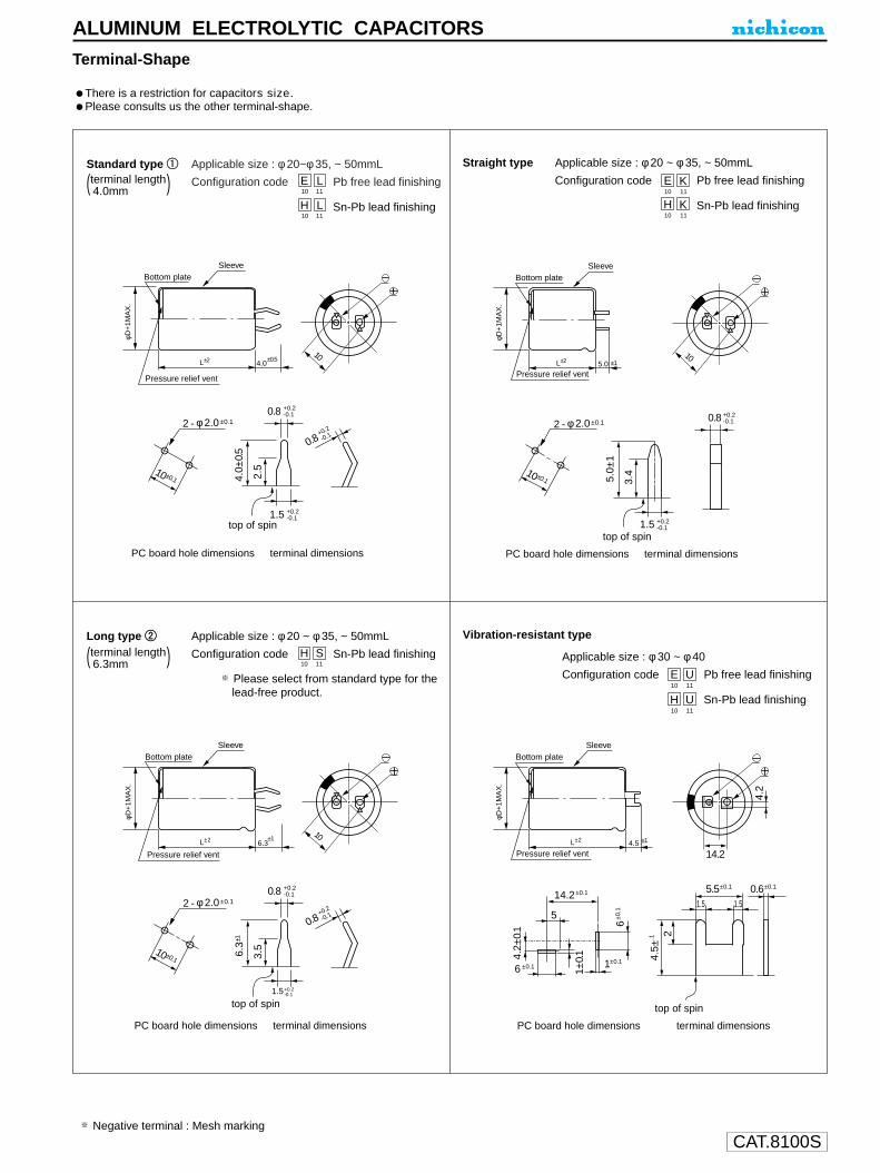
CAT.8100S
Terminal-Shape
There is a restriction for capacitors size.Please consults us the other terminal-shape.
Standard type 11 Applicable size : φ20~φ 35, ~ 50mmL
Configuration code Pb free lead finishing
Configuration code Sn-Pb lead finishing
E10
L11
H10
L11
Negative terminal : Mesh marking
Straight type Applicable size : φ 20 ~ φ 35, ~ 50mmL
Configuration code Pb free lead finishing
Configuration code Sn-Pb lead finishing
E10
K11
H10
K11
Long type 22 Applicable size : φ 20 ~ φ 35, ~ 50mmL
Configuration code Sn-Pb lead finishingH10
S11
Applicable size : φ 30 ~ φ 40
Configuration code Pb free lead finishing
Configuration code Sn-Pb lead finishing
E10
U11
H10
U11
ALUMINUM ELECTROLYTIC CAPACITORS
SleeveBottom plate
Pressure relief vent
L±2 4.0
φD+
1MA
X.
±0.5
10 ±0.1
2 - φ 2.0±0.1
4.0±
0.5
2.5
1.5
0.8
+0.2-0.1
+0.2
-0.1
0.8 +0.2-0.1
10
terminal dimensionsPC board hole dimensions
top of spin
10
SleeveBottom plate
Pressure relief vent
L±2 6.3
φD+
1MA
X.
±1
10 ±0.1
2 - φ 2.0±0.1
6.3±
1
3.5
0.8+0.2
-0.1
0.8 +0.2-0.1
1.5+0.2-0.1
terminal dimensionsPC board hole dimensions
top of spin
SleeveBottom plate
Pressure relief ventL±2 4.5
φD+
1MA
X.
±1
4.5±
.1 2
5.5±0.1 0.6±0.1
14.2
4.2
4.2±
0.1
1±0.
1
1±0.1
6±0
.1
14.2±0.1
6 ±0.1
1.5 1.55
terminal dimensionsPC board hole dimensions
top of spin
1.5 +0.2-0.1
terminal dimensionsPC board hole dimensions
top of spin
SleeveBottom plate
Pressure relief ventL±2 5.0
φD+
1MA
X.
±1
10 ±0.1
2 - φ 2.0±0.1
5.0±
1
3.4
10
0.8 +0.2-0.1
(terminal length 4.0mm )
(terminal length 6.3mm )
Please select from standard type for thelead-free product.
Vibration-resistant type

CAT.8100S
U1
T2
M3
14
A5
36
37
08
M9
P10
D11
Configuration
Capacitance tolerance (M : ±20%, K : ±10%)
Rated Capacitance (33µF)
Rated voltage (10V)
Series name
Type
Pressurerelief vent
L+1MAX 15MIN 4MIN
φd
φD+
0.5
MA
X
φD
P
φd
6.3
2.5
0.5
8
3.5
0.6
10
5.0
0.6
12.5
5.0
0.6
16
7.5
0.8
P±0
.5
Sleeve (P.E.T.)
φ D
6.3
Pb free lead finishingPb free PET sleeve
Sn-Pb lead finishingPVC sleeve contain Pb
ED EA
8 · 10 PD PA
12.5 · 16 HD HA
Configuration
Please contact to us if other configurations are required.
ALUMINUM ELECTROLYTIC CAPACITORS
TM series
Timer Circuit Use
Ideally suited for timer circuits.Excellent leakage current stability, even subjected to load or no load at high temperaturefor a long time.
Radial Lead Type
Dimensions
Type numbering system (Example : 10V 33µF)
Specifications
Category Temperature Range
Rated Voltage Range
Rated Capacitance Range
Capacitance Tolerance
Leakage Current
tan δ
Stability at Low Temperature
Endurance
Shelf Life
Marking
Performance CharacteristicsItem
–40 ~ +85°C
10 ~ 50V
1 ~ 470µF
±20% (M) (±10% (K) semi-standard) at 120Hz, 20°C
After 2 minutes' application of rated voltage, leakage current is 0.001CV+1 (µA) or less.
Printed with white color letter on black sleeve.
Measurement frequency : 120Hz
After 2000 hours' application of rated voltageat 85°C, capacitors meet the characteristicsrequirements listed at right.
After leaving capacitors under no load at 85°C for 1000 hours, they meet the requirementsfor endurance characteristics listed above.
Rated voltage (V)tan δ (MAX.)
100.17
160.13
250.10
500.08
D × L (mm)
TM HighStability KL
Z–25°C / Z+20°C
Z–40°C / Z+20°C
Rated voltage (V)
Impedance ratioZT / Z20 (MAX.)
1024
1623
251.52
501.52
Capacitance change
Leakage current
tan δWithin ±10% of initial value150% or less of initial specified valueInitial specified value or less
Measurement frequency : 120Hz, Temperature : 20°C
12.23.34.7
10223347
100220330470
0102R23R34R7100220330470101221331471
6.3 × 118 × 11.58 × 11.5
10 × 1610 × 20
12.5 × 2512.5 ×25
1ACap.
(µF)
V 10
Code
6.3 × 118 × 11.5
10 × 12.510 × 12.510 × 20
12.5 × 2516 × 2516 × 25
1C
16
6.3 × 116.3 × 11
8 × 11.510 × 12.510 × 1610 × 16
12.5 × 2016 × 2516 × 2516 × 31.5
1E
25
6.3 × 116.3 × 116.3 × 11
8 × 11.510 × 12.510 × 1610 × 20
12.5 × 2012.5 × 25
16 × 31.5
1H
50
Please refer to page 19, 20, 21 about the formed or taped product spec.Please refer to page 3 for the minimum order quantity.

CAT.8100S
Type • Classification
Complied
Eco-Products “GeoCap”
Nichicon promotes environmentally conscious practices.
Nichicon offers “GeoCap”,which has completely lead free terminals and contains no polyvinylchloride in the sleeve.
Reisin-Molded type
Conformal
Coated type
F91, F92, F93, F97, F98
F95, F72, F75
Surface
Mount type
No polyvinyl chloride
contained
Series Lead-Free Compliance Anti Polyvinyl Chloride Compliance
SOLID TANTALUM ELECTROLYTIC CAPACITORS
Solid Tantalum Electrolytic Capacitors

CAT.8100S
SOLID TANTALUM ELECTROLYTIC CAPACITORS
The schematics, graphs and numerical values that appear in our catalog are a representative sampling of typical usage. These will differ dueto series, ratings and lot variation. Therefore, please contact your local Nichicon sales office to confirm the specific characteristics.
1. Rated Voltage and Operating VoltageAs shown in Fig.1, rated voltage signifies the maximum peak volatge applied to the capacitor at the maximum rated temperature. The ratedvoltage consists of the sum of both DC voltage and ripple peak voltage. It is recommended that capacitors be used at a voltage less than therated voltage. (Reduce rated voltage should be applied at higher than 85˚Ctemperature)
It is also recommended to properly derate the voltage to improve operating reliability.
The NASA APPLICATION NOTE shown in Fig.2 is commonly used to consider the derated voltage.
2. Low Impedance CircuitIn low impedance circuit applications such as power supply circuits, the failure rate may increase due to inrush current. Additionally, if a shortoccurs within the capacitor, burning may possibly occur. Therefore, sufficient voltage derating (less than 1/2 to rated voltage) isrecommended. If you need assistance, please contact your local Nichicon sales office.
3. Operating TemperatureAll parts must be used within the specified category temperature range, since, the temperature has a great effect on reliability. Therefore,when using capacitors, please try to keep the temperature as low as possible. Please take into consideration that the capacitor itselfgenerates heat which affects the atmospheric temperature.
4. Ripple CapabilityThe ripple capability of solid tantalum electrolytic capacitors is defined by both Equivalent Series Resistance (ESR) and power dissipationdue to ripple current.If the capacitor sees a higher than specified amount of ripple current, heat generation within the capacitor will increase eventually causing afailure.The capacitors should be used at a voltage less than the rated voltage that consists of the sum of both DC voltage and ripple peak voltage.Also, reverse voltage due to variation of ripple peak voltage should not be applied to the capacitor.If you need detailed information about permissible ripple voltage and permissible ripple current, please contact your local Nichicon salesoffice.
5. Reverse VoltageSolid tantalum electrolytic capacitors are polarized, and therefore, no reverse voltage is acceptable. (Electrical characteristics shall bedeteriorated when reverse voltage is applied.) When checking a part using a tester, please make sure the polarity of the tester before theprobes touch both capacitor terminals.
APPLICATION GUIDELINESFOR SOLID TANTALUMELECTROLYTIC CAPACITORS
--70
0.8
0.5
0.4
0.2
--45 --20 5 30 55 80 105 130
Coeffic
ient of R
ecom
mend
ab
leO
pera
ting
Volta
ge
Ambient Temperature (oC)
Time (sec.)
Voltage(V)
Rated Voltage
Operating Voltage
DC Voltage
Ripple Voltage
++ +~
-
+
-
Low impedance circuitFilter
ICPowersupplycircuit
By-pass
Fig. 3Fig. 3
Fig. 2
Fig. 1

6. Low voltage application or High resistance connected to the capacitor in seriesA problem could possibly result if the following application exixts:Low voltage, high resistance conncected to the capacitor in series, and a circuit sensitive to leakage current. A problem could occur due tothe lower recovery of the leakage current characteristic of tantalum capacitor, caused by heat stress during the soldering process.
7. Caution When Mounting7-1. Recommemded mounting pad dimensions for chip type are as shown in Table 1 and Table --2. Dimensions may vary depending upon reflow
conditions, type of solder and/or board size.
[Cautions when mounting F72, F75 and F95 chip]Adjustment of ∆C toward anode side is required when mounting, as there is a difference between the center of total length of anode tab (portion) and the center of board land dimension.
7-2. Soldering temperature and soldering time for chip type should be within limits as shown below when measured at terminal surface.In case you repeat soldering process more than 1 time, please contact your local Nichicon sales office to get advice.Board size, distribution of reflow's temperature and capacitor'sposition on the circuit board will influence to reflow conditions. Please check real reflow condition before applying condition shown in Fig. 5.In case you repeat soldering process more than 1 time, please contact your local Nichicon sales office to get advice.
• Reflow (Infrared Ray, Hot Plate, Hot Air, etc.)
• Vapor Phase Soldering30 sec. max. at 215˚C (Pre-heat is subject to "Reflow".)
CAT.8100S
+-
b´ c
a
b
c
Center of nozzle
Type F92 • F93 • F97 • F98Case a b b´ c
M 0.65 0.5 0.5 0.6J 0.8 1.0 1.0 0.8P 1.1 1.3 1.3 0.8A 1.4 2.0 2.0 1.2B 2.7 2.1 2.1 1.4C 2.6 2.5 2.5 2.8N 2.8 2.8 2.8 4.3
Table-1Type F95
Case a b b´ c cP 1.4 0.6 0.5 0.7 +0.2S 1.7 0.7 0.6 1.1 +0.2A 1.8 0.7 0.6 1.1 +0.2B 2.6 0.8 0.7 1.1 +0.2
Table-2 (mm)
In the case of F95 chip mounting, make thecentering with the dimensions except anode tab( portion) length.
Fig. 4
F72 • F75a b b´ c ∆c
F72 R 5.8 1.2 1.2 3.9 0.5F75 C 3.0 1.2 1.2 3.3 0.5F75 D 4.1 1.2 1.2 3.9 0.5F75 R 5.8 1.2 1.2 3.9 0.5
Table-3
Type
Tem
p. (
o C
)
Time (Sec.)
170
150
140
130 200
220
240
260
60 90 120 150 180 10 20 30 40 50
160
Pre-heat
ReflowFig. 5

• Flow (Dipping, Wave Soldering, etc.)
• Soldering-iron (30 watts or less)
NOTE : Preheat is required to reduce heat shock regardless of the method of soldering. Preheat time for F72, F75 and F95 series should be aslong as possible.
7-3. CleaningPlease wash P.C. board as soon as possible after soldering process to eliminate flux, and acid and alkaline material.In case of ultrasonic cleaning, attention should be paid to the following:qCleaning condition : Frequency=25~40kHz,
Power=10~20W/r, Time = within 3 minutes.wDo not allow a circuit board to touch the agitator.eDo not stack circuit boards in the cleaning bath.
8.Cantions on designing• When tantalum capacitor is used at high frequency circuit, please note that the electrical characteristics may change drastically.• Leakage current value differs depending on the voltage applied.Please use higher ratings, especially when it is used in the integration circuit or time-constant circuit.
9. Notes on Storage• It is desirable to store capacitors at normal temperatures 35˚C Max. and normal humidity.• Keep out of direct sunlight.• Don't apply force to capacitor's body and especially terminal.• Don't apply shock and vibration by dropping etc.• It is preferable to store for no more than 1 year under the above condition.(when you use part that has been stored more than 1 year, please contact your local sales office to have assistance)
10. Disposal of capacitorsWhen disposing, scrap it as industrial wastes.
11. Others
q The above mentioned material is according to EIAJ RCR-2368B (revised in March 2002, titled “Guideline of notabilia for fixed tantalumelectrolytic capacitors with solid electrolyte for use in electronic equipment”). Please refer to this book for details.
w Please refer to Nichicon individual technical material for further information of q and contents in this catalog.
The corelations among rated voltage, surge voltage at 85˚C and derated voltage at 125˚C are as shown.
SOLID TANTALUM ELECTROLYTIC CAPACITORS
CAT.8100S
200
220
240
260
5 10 15 20
Tem
p. (
o C
)Time (Sec.)
Pre-heat
SolderingTe
mp
. (o C
)
Time (Sec.)
320
350
290
2602 4 6 8
Rated voltage (V) 2.5 4 6.3 10 16 20 25 3585˚C Surge voltage (V) 3.2 5.2 8 13 20 26 32 46125˚C Derated voltage (V) 1.6 2.5 4 6.3 10 13 16 22
Fig. 6
Fig. 7
(Pre-heat is subject to "Reflow.")

CAT.8100S
SOLID TANTALUM ELECTROLYTIC CAPACITORS
F92
F98
F91
F93
F97
F95
F72
F75
P
A
B
A
B
CC
N
P
S • A
B
3000
2500
2500
2000
2000
500
500
3000
2500
2000
8000
8000
M
J
4000
4000
8000
8000
6000
2500
2500
10000
10000
8500
R
C • D • R
1000
500
A
F 9 5 V1 1 5 5 M A
Capacitance tolerance
Rated CapacitanceRated voltage
Series Case code
A
F 9 3 J0 1 0 6 M A A
A Q 2
Carrier Tape Dimensions (mm)
F91 • F92 • F93 • F97
0.2~0.3
t2
B
4.0 0.1 1.5 1.75 0.1
A P1
FW
2.0 0.05
Reel Dimensions (mm)
F95 • F72 • F75
Type numbering system
F95 series have single-side electrode structures as illustrated below, code "AQ2" is added at the end of each type number to distinguish from other case sizes.
Their electrode area at thecover tape side becomes lessened, accordingly
0.2~0.3
t2 P1
1.54.0 0.1
1.75 0.1
2.0 0.05
FW
B
Tape Width (mm)
Taping Code Applicable Case Size
8
12
Reel Diaφ180mm
Reel Diaφ330mm
F72 • F75F95
A E
C G
M • J • P • A • B
C • N
(mm)
(mm)
Standard Pakaging Quantity
Item
Item
Reel Diameter
Tape width
Series Case codeQ'ty (pcs./reel)
Reel Dia. φ180 Reel Dia. φ330
+0.1 -0 +0.1
-0
Polarity
RAnode is at opposite side of feeding holes.
Note: The above shows the dimensions of φ180 reel. In case of φ330 reel, the appearance shape is slightly different.
( ) R
Anode is at opposite side of feeding holes. ( )
9.0 ± 0.3
11.4 ± 1.0
13 ± 0.3
15.4 ± 1.0
A
W1
W2
φ180
φ180
φ330
φ330 ± 2+0–3
8 12
Case code
(mm)
Figures in ( ) at t2 are applicable to F92 series.
P
A
M
J
B
C
W A
8.0 0.3
8.0 0.3
12.0 0.3
1.5 0.1 2.3 0.1
3.5 0.05
5.5 0.05
4.0 0.1
3.5 0.05 4.0 0.1
8.0 0.1
3.5 0.1
1.9 0.05
1.8 0.1
3.8 0.1
6.0 0.1
1.9 0.1
1.08 0.08
1.0 0.1
3.3 0.1
3.6 0.1
B F P1 t2
(1.7MAX)
(1.3MAX)
2.9MAX
1.1MAX
N 7.7 0.14.8 0.1 3.5MAX
2.1MAX (1.7)
2.4MAX (1.7)
P • S • A • B
F92 • F93 F91
F97 • F98
C • D • R
(mm)
Case codeType
S
P
A
B
R
C
F72
DF75
R
F95
W A
8.0 0.3
12.0 0.3
2.0 0.2 3.6 0.23.5 0.05
5.5 0.1
4.0 0.1
8.0 0.1
3.7 0.22.1 0.2
3.1 0.2
7.6 0.2
4.8 0.2 7.9 0.2
6.5 0.2
3.7 0.2
7.6 0.26.5 0.2
B F P1 t2
1.5MAX
1.4 0.2 2.6 0.2 1.5MAX
2.0MAX
2.4MAX
2.2MAX
3.9MAX
3.6MAX
4.6MAX
F98
2 0.513 0.2
A
50MIN
W2
W1
4.0 0.1
1.5
1.75 0.1
P1
F
A
t2 2.0 0.05
+0.1 -0
B
1 2 3 4 5 6 7 8 9 10 11 12 13 14
Taping Specifications for Automatic Insertion(Chip Type Capacitors)

CAT.8100S
SeriesVoltage (6.3V)
CapacitanceLot No.
CapacitanceLot No.
X2
33 j
UA
Plastic platform
0.3MAX.
L±0.3
φD±0
.5
B±0
.2
C±0.2
0.5M
AX
.
A±0
.2A
±0.2
E
H
Positive
Negative
SeriesVoltage (16V)Trade mark
Plastic platform
0.3MAX.
L±0.5
φD±0
.5
B±0
.2
C±0.2
0.5M
AX
.
A±0
.2A
±0.2
E
H
Positive
Negative
X2
100C
UA
Pressure relief vent
U1
U2
A3
14
C5
16
07
08
M9
C10
R11
112
G13
S14
Configuration
Taping code
Capacitance tolerance (±20%)
Rated Capacitance (100µF)
Rated voltage (1.6V)
Series name
Type
φD
4 ~ 6.3
8 • 10
Code
CR
NR
(mm)
A
B
C
E
L
H
4 × 5.8
1.8
4.3
4.3
1.0
5.8
0.5 ~ 0.8
5 × 5.8
2.1
5.3
5.3
1.3
5.8
0.5 ~ 0.8
6.3 × 5.8
2.4
6.6
6.6
2.2
5.8
0.5 ~ 0.8
6.3 × 7.7
2.4
6.6
6.6
2.2
7.7
0.5 ~ 0.8
8 × 10
2.9
8.3
8.3
3.1
10
0.8 ~ 1.1
10 × 10
3.2
10.3
10.3
4.5
10
0.8 ~ 1.1
Chip Type Type numbering system (Example : 16V 10µF)
ALUMINUM ELECTROLYTIC CAPACITORS
UA series
6mmL Chip Type, Long Life Assurance
Chip type with load life of 3000~5000 hours at +105°C.Designed for surface mounting on high density PC board.
Specifications
Category Temperature Range
Rated Voltage Range
Rated Capacitance Range
Capacitance Tolerance
Leakage Current
tan δ
Stability at Low Temperature
Endurance
Shelf Life
Resistance to soldering
heat
Marking
Performance CharacteristicsItem
–55 ~ +105°C
6.3 ~ 50V
0.1 ~ 1000µF
±20% at 120Hz, 20°C
After 2 minutes' application of rated voltage, leakage current is not more than 0.01 CV or 3 (µA) , whichever is greater.
Black print on the case top.
After 3000 hours' (5000 hours for φ8, φ10)application of rated voltage at 105°C ,capacitors meet the characteristicrequirements listed at right.
After leaving capacitors under no load at 105°C for 1000 hours,they meet the specified value for endurance characteristics listed above.
UALong LifeUT
Measurement frequency : 120Hz, Temperature : 20°C
Measurement frequency : 120Hz
Z–25°C / Z+20°C
Z–55°C / Z+20°C
Rated voltage (V)
Impedance ratioZT / Z20 (MAX.)
1037
6.3410
1625
2523
3523
5023
Rated voltage (V)tan δ (MAX.)
500.12
350.13
250.16
160.20
100.24
6.30.28
Within ±30% of initial value
Initial specified value or less300% or less of initial specified value
Capacitance changetan δLeakage current
Capacitance change
Leakage current
tan δWithin ±10% of initial value
Initial specified value or lessInitial specified value or less
The capacitors shall be kept on the hot plate maintained at 250°Cfor 30 seconds. After removing from the hot plate and restored at room temperature, they meet the characteristic requirementslisted at right.
Dimension table in next page.
(φ4 ~ 6.3)
(φ8, φ10 ×10L)
VoltageV 6.3 10 16 25 35 50
Code j A C E V H
• The lead-free product is also available upon request.In this case, will be put at 11th digit of type numbering system.L

CAT.8100S
Dimensions
Rated Ripple (mA rms) at 105°C 120Hz
0.1
0.22
0.33
0.47
1
2.2
3.3
4.7
10
22
33
47
100
220
330
470
1000
0R1
R22
R33
R47
010
2R2
3R3
4R7
100
220
330
470
101
221
331
471
102
4 ×5.8
5 ×5.8
5 ×5.8
6.3 ×5.8
6.3 ×7.7
8 ×10
10 ×10
10 ×10
22
35
38
69
120
290
320
410
5 ×5.8
5 ×5.8
6.3 ×5.8
6.3 ×7.7
8 ×10
10 ×10
10 ×10
30
35
50
81
141
290
320
4 ×5.8
5 ×5.8
6.3 ×5.8
6.3 ×5.8
6.3 ×7.7
10 ×10
10 ×10
10 ×10
18
30
48
50
81
216
290
320
5 ×5.8
6.3 ×5.8
6.3 ×5.8
6.3 ×7.7
8 ×10
10 ×10
10 ×10
27
44
50
63
116
320
450
4 ×5.8
5 ×5.8
6.3 ×5.8
6.3 ×7.7
8 ×10
10 ×10
10 ×10
16
27
44
57
92
151
375
4 ×5.8
4 ×5.8
4 ×5.8
4 ×5.8
4 ×5.8
4 ×5.8
4 ×5.8
5 ×5.8
6.3 ×5.8
6.3 ×7.7
8 ×10
8 ×10
10 ×10
Case size
1
2.6
3.2
5
8
12
17
22
32
58
140
170
310
0J
6.3
1A
10
1C
16
1E
25
1V
35
1H
50V
CodeCap.(µF)
Ratedripple
Please refer to page 3 for the minimum order quantity.
Taping Specifications are given in page 22.
Frequency coefficient of rated ripple current
CoefficientFrequency 50 Hz 120 Hz 300 Hz 1 kHz 10 kHz~
0.70 1.00 1.17 1.36 1.50
UA series
ALUMINUM ELECTROLYTIC CAPACITORS
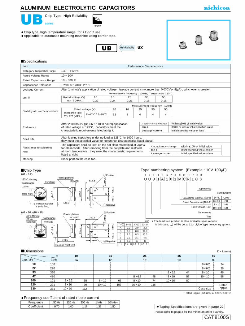
CAT.8100SPlease refer to page 3 for the minimum order quantity.
Taping Specifications are given in page 22.
Frequency coefficient of rated ripple current
CoefficientFrequency 50 Hz 120 Hz 300 Hz 1 kHz 10 kHz~
0.70 1.00 1.17 1.36 1.50
VoltageCapacitance
125°C Marking
Lot No.
Plastic platform0.3MAX.
φD±0
.5
B±0
.2
A±0
.2A
±0.2
C±0.2
0.5M
AX
.E
H
H
Positive
Negative
Plastic platform
Pressure relief vent
0.3MAX.
φD±0
.5
B±0
.2
A±0
.2A
±0.2
C±0.2
0.5M
AX
.E
Positive
Negative
U1
U2
B3
14
A5
16
07
18
M9
C10
R11
112
G13
S14
Configuration
Taping code
Capacitance tolerance (±20%)
Rated Capacitance (100µF)
Rated voltage (10V)
Series name
Type
D × L
8 × 6.2
8 × 10
Code
CR
NR
10 × 10 NR
L±0.3
L±0.5
8 × 6.2D × L
AB
CE
3.38.38.3
2.3
8 × 102.98.38.3
3.1
10 × 103.2
10.310.3
4.5L 6.2 10 10H 0.5 ~ 0.8 0.8 ~ 1.1 0.8 ~ 1.1
(mm)Voltage
CapacitanceLot No.Trade mark
Trade mark
125°C Marking
A2E
330
10V
A2E
100
10V
Voltage mark for6.3V is 6V .
UB series
Chip Type, High Reliability
Chip type, high temperature range, for +125°C use.Applicable to automatic mounting machine using carrier tape.
Chip Type(φ8 × 6.2)
(φ8 × 10, φ10 × 10)
Specifications
Category Temperature Range
Rated Voltage Range
Rated Capacitance Range
Capacitance Tolerance
Leakage Current
tan δ
Stability at Low Temperature
Endurance
Shelf Life
Resistance to soldering
heat
Marking
Performance CharacteristicsItem
–40 ~ +125°C
10 ~ 50V
10 ~ 330µF
±20% at 120Hz, 20°C
After 1 minute's application of rated voltage, leakage current is not more than 0.03CVor 4(µA) , whichever is greater.
Black print on the case top.
Measurement frequency : 120Hz
After 2000 hours' (φ8 × 6.2 : 1000 hours) applicationof rated voltage at 125°C, capacitors meet thecharacteristic requirements listed at right.
After leaving capacitors under no load at 125°C for 1000 hours, they meet the specified value for endurance characteristics listed above.
Z–40°C / Z+20°C
Rated voltage (V)
Impedance ratioZT / Z20 (MAX.)
10
12
16
8
25
6
35
4
50
4
UB UX
Type numbering system (Example : 10V 100µF)
The capacitors shall be kept on the hot plate maintained at 250°Cfor 30 seconds. After removing from the hot plate and restoredat room temperature, they meet the characteristic requirementslisted at right.
D × L (mm)
Rated Ripple (mA rms) at 125°C 120Hz
Dimensions
10223347
100220330
100220330470101221331
8 × 6.28 × 10
10 × 10
8 × 1010 × 10
8 × 6.28 × 10
10 × 10
8 × 6.28 × 10
10 × 10
8 × 6.28 × 6.28 × 10
10 × 10
Case size
5890
112
66102
4874
116
445280
24384658
1A 1C 1E 1V 1H
10 16 25 35 50VCodeCap.(µF)
Ratedripple
Rated voltage (V)tan δ (MAX.)
100.32
160.24
250.21
350.18
500.18
Measurement frequency : 120Hz, Temperature : 20°C
Capacitance change
Leakage current
tan δWithin ±10% of initial value
Initial specified value or lessInitial specified value or less
Capacitance change
Leakage current
tan δWithin ±30% of initial value
Initial specified value or less300% or less of intial specified value
High Reliability
ALUMINUM ELECTROLYTIC CAPACITORS
• The lead-free product is also available upon request.In this case, will be put at 11th digit of type numbering system.L
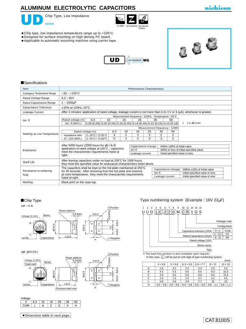
CAT.8100S
ALUMINUM ELECTROLYTIC CAPACITORS
N2
22C
UD
N2
100V
UD
0.3 MAX.
φD±0
.5
B±0
.2
A±0
.2A
±0.2
C±0.2
0.5
MA
X.
E
H
H
0.3 MAX.
φD±0
.5
B±0
.2
A±0
.2A
±0.2
C±0.2
0.5
MA
X.
E
L±0.3
L±0.5
Series
CapacitanceLot No.
Lot No. Capacitance
Plastic platform
Plastic platform
SeriesTrade mark
Voltage (C:16V)
Voltage (V:35V)
Negative
Positive
Negative
Positive
Pressure relief vent
U1
U2
D3
14
C5
26
27
08
M9
C10
R11
112
G13
S14
D × L
4 ~ 6.3
8 • 10
CR
NR
Configuration
Package code
Capacitance tolerance (±20%)
Rated Capacitance (22µF)
Rated voltage (16V)
Series name
Type
Code
(mm)
ABCELH
4 × 5.8
1.84.34.31.05.8
0.5 ~ 0.8
5 × 5.8
2.15.35.31.35.8
0.5 ~ 0.8
6.3 × 5.8
2.46.66.62.25.8
0.5 ~ 0.8
6.3 × 7.7
2.46.66.62.27.7
0.5 ~ 0.8
8 × 10
2.98.38.33.110
0.8 ~ 1.1
10 × 10
3.210.310.34.510
0.8 ~ 1.1
UD series
Chip Type, Low Impedance
Chip type, low impedance temperature range up to +105°C.Designed for surface mounting on high density PC board.Applicable to automatic mounting machine using carrier tape.
Chip Type
Specifications
Category Temperature Range
Rated Voltage Range
Rated Capacitance Range
Capacitance Tolerance
Leakage Current
tan δ
Stability at Low Temperature
Endurance
Shelf Life
Resistance to soldering
heat
Marking
Performance CharacteristicsItem
–55 ~ +105°C
6.3 ~ 50V
1 ~ 1500µF
±20% at 120Hz, 20°C
After 2 minutes' application of rated voltage, leakage current is not more than 0.01 CV or 3 (µA), whichever is greater.
Black print on the case top.
After 5000 hours' (2000 hours for φD 6.3)application of rated voltage at 105°C , capacitorsmeet the characteristic requirements listed atright.
After leaving capacitors under no load at 105°C for 1000 hours,they meet the specified value for endurance characteristics listed above.
Type numbering system (Example : 16V 22µF)
Measurement frequency : 120Hz, Temperature : 20°C
Measurement frequency : 120Hz
( ) is φ8 over
Z–25°C / Z+20°C
Z–55°C / Z+20°C
Rated voltage (V)
Impedance ratioZT / Z20 (MAX.)
1624
1024
6.335
2523
3523
5023
Rated voltage (V)tan δ (MAX.)
500.12 (0.14)
350.12 (0.14)
250.14 (0.16)
160.16 (0.20)
100.20 (0.24)
6.30.26 (0.28)
Within ±30% of initial value
Initial specified value or less200% or less of initial specified value
Capacitance changetan δLeakage current
Capacitance change
Leakage current
tan δWithin ±10% of initial value
Initial specified value or lessInitial specified value or less
The capacitors shall be kept on the hot plate maintained at 250°Cfor 30 seconds. After removing from the hot plate and restored at room temperature, they meet the characteristic requirementslisted at right.
UD
(φ4 ~ 6.3)
(φ8, φ10×10L)
Dimension table in next page.
VoltageV 6.3 10 16 25 35 50
Code j A C E V H
WGLow Impedance
• The lead-free product is also available upon request.In this case, will be put at 11th digit of type numbering system.L

CAT.8100S
1
2.2
3.3
4.7
10
15
22
27
33
47
56
68
100
150
220
330
470
680
1000
1500
010
2R2
3R3
4R7
100
150
220
270
330
470
560
680
101
151
221
331
471
681
102
152
4 × 5.8
5 × 5.8
5 × 5.8
5 × 5.8
6.3 × 5.8
6.3 × 5.8
6.3 × 5.8
6.3 × 5.8
6.3 × 7.7
8 × 10
8 × 10
8 × 10
10 × 10
1.80
0.76
0.76
0.76
0.44
0.44
0.44
0.44
0.34
0.17
0.17
0.17
0.09
80
150
150
150
230
230
230
230
280
450
450
450
670
1H
50
0J
6.3
1A
10
1C
16
1E
25
1V
35
4 × 5.8
5 × 5.8
5 × 5.8
6.3 × 5.8
6.3 × 5.8
6.3 × 5.8
6.3 × 5.8
6.3 × 5.8
6.3 × 7.7
8 × 10
8 × 10
10 × 10
10 × 10
1.80
0.76
0.76
0.44
0.44
0.44
0.44
0.44
0.34
0.17
0.17
0.09
0.09
80
150
150
230
230
230
230
230
280
450
450
670
670
4 × 5.8
5 × 5.8
5 × 5.8
6.3 × 5.8
6.3 × 5.8
6.3 × 5.8
6.3 × 5.8
6.3 × 5.8
6.3 × 7.7
6.3 × 7.7
8 × 10
8 × 10
10 × 10
1.80
0.76
0.76
0.44
0.44
0.44
0.44
0.44
0.34
0.34
0.17
0.17
0.09
80
150
150
230
230
230
230
230
280
280
450
450
670
4 × 5.8
5 × 5.8
5 × 5.8
6.3 × 5.8
6.3 × 5.8
6.3 × 5.8
6.3 × 5.8
6.3 × 5.8
6.3 × 7.7
8 × 10
8 × 10
8 × 10
10 × 10
1.80
0.76
0.76
0.44
0.44
0.44
0.44
0.44
0.34
0.17
0.17
0.17
0.09
80
150
150
230
230
230
230
230
280
450
450
450
670
4 × 5.8
5 × 5.8
5 × 5.8
5 × 5.8
6.3 × 5.8
6.3 × 5.8
6.3 × 5.8
6.3 × 7.7
6.3 × 7.7
8 × 10
8 × 10
8 × 10
10 × 10
1.80
0.76
0.76
0.76
0.44
0.44
0.44
0.34
0.34
0.17
0.17
0.17
0.09
80
150
150
150
230
230
230
280
280
450
450
450
670
4 × 5.8
4 × 5.8
4 × 5.8
5 × 5.8
6.3 × 5.8
6.3 × 5.8
6.3 × 5.8
6.3 × 7.7
6.3 × 7.7
6.3 × 7.7
8 × 10
8 × 10
8 × 10
10 × 10
10 × 10
5.00
5.00
5.00
1.52
0.88
0.88
0.88
0.68
0.68
0.68
0.34
0.34
0.34
0.18
0.18
30
30
30
85
165
165
165
185
185
185
300
300
300
670
670
V
CodeCap.(µF)
ImpedanceCase sizeRatedripple
UD series
Dimensions
Max. impedance (Ω) at 20°C 100kHz, Rated Ripple (mA rms) at 105°C 100kHz
ALUMINUM ELECTROLYTIC CAPACITORS
Please refer to page 3 for the minimum order quantity.
Taping Specifications are given in page 22.
Frequency coefficient of rated ripple current
CoefficientFrequency 50 Hz 120 Hz 300 Hz 1 kHz 10 kHz~
0.35 0.50 0.64 0.83 1.00

CAT.8100S
4.71022334768
100220330470
220330470
10002200330047006800
10000
Endurance
tan δ
Stability at Low Temperature 5 4 3 2 2 2 2 2 3 6
Item
After 2000 hours' application of rated voltage at 85°C, capacitors meet thecharacteristic requirements listed at right.
12 10 8 5 4 3 3 3 6 10
6.3 10 16 25 35 50 63 100 160 ~ 250 400 • 450
For capacitance of more than 1000µF, add 0.02 for every increase of 1000µF.
Z–25°C / Z+20°C
Z–40°C / Z+20°C
120Hz
20°C
Rated voltage (V)
0.28 0.24 0.20 0.16 0.14 0.12 0.10 0.08 0.20 0.25
–40 ~ +85°C 6.3 ~ 450V4.7 ~ 10000µF±20% at 120Hz, 20°C
Rated voltage (V)
Rated voltage (V)
Impedance ratio
ZT / Z20 (MAX.)
After leaving capacitors under no load at 85°C for 1000 hours, they meet the specifiedvalue for endurance characteristics listed above.
Black print on the case top.
6.3 ~ 100 160 ~ 450
After 1 minutes' application of rated voltage, leakage current is not more than 0.03CV or 4 (µA), whichever is greater. I = 0.04CV+100 (µA) max.(1 minute's)
tan δ (MAX)
6.3 10 16 25 35 50 63 100 160 ~ 250 400 • 450 120Hz
—
Category Temperature RangeRated Voltage RangeRated Capacitance RangeCapacitance Tolerance
Leakage Current
Shelf Life
Marking
Initial specified value or lessWithin ±20% of initial value200% or less of initial specified value
Leakage current
tan δCapacitance change
Performance Characteristics
Specifications
U1
U2
G3
14
H5
36
37
18
M9
N10
R11
112 13 14
Configuration
Package code
Taping
Tray
MS
ZD
Capacitance Tolerance (±20%)
Rated Capacitance(330µF)
Rated voltage(50V)
Series name
Type
φD
12.5 ~ 18
20
Code
NR
RR
ALUMINUM ELECTROLYTIC CAPACITORS
UG series
Chip Type, Higher Capacitance Range
Chip Type, higher capacitance in larger case sizes (φ12.5, φ16, φ18, φ20) Designed for surface mounting on high density PC board.Applicable to automatic mounting machine using carrier tape and tray.
Type numbering system (Example : 50V 330µF)
Dimensions
Size φ12.5×21 is available for capacitors marked," ". Size φ16×21.5L is available for capacitors marked," ". Size φ20×16.5L is available for capacitors marks," ".
D × L (mm)
450520740
1150
12.5 × 13.516 × 16.518 × 16.518 × 21.520 × 21.5
115140275345
RatedRipple
6.3 10 16 25 35 50
12.5 × 13.512.5 × 13.5
16 × 16.518 × 21.5
0J 1A 1C 1E 1V 1H221331471102222332472682103
12.5 × 16.016 × 16.516 × 16.518 × 16.518 × 21.5
8901200140016502000
12.5 × 13.512.5 × 16.0
16 × 16.518 × 16.518 × 21.520 × 21.5
620960
1300150018502200
12.5 × 13.516 × 16.518 × 16.518 × 21.5
710115014501750
12.5 × 13.512.5 × 16.0
18 × 16.518 × 21.5
550820
13501700
12.5 × 13.516 × 16.518 × 21.5
58010001550
Cap. Code(µF)
V
63 100 160 200 250 400 450
1J 2A 2C 2D 2E 2G 2W4R7100220330470680101221331471
12.5 × 13.512.6 × 16.0
16 × 16.518 × 16.5
370580680850
12.5 × 13.512.5 × 16.0
18 × 16.518 × 21.5
350440665825
12.5 × 16.016 × 16.518 × 16.5
370500590
12.5 × 13.512.5 × 16.0
16 × 16.518 × 16.518 × 21.5
235310415505590
12.5 × 13.512.5 × 16.0
16 × 16.518 × 16.518 × 21.5
150240340415490
115140280350430
12.5 × 13.516 × 16.516 × 21.518 × 21.5
Case size
Cap. Code
(µF)V
Rated Ripple (mA rms) at 85°C 120Hz
Chip Type
nic
hic
on
330
µFUG
5
0VH
9736
φ D
±0.5
L±0.5
H±0.1
12.54.013.616.08.02.5
φDABCEH
16.4.517.119.510.53.75
18.5.019.121.511.53.75
20.5.021.123.513.53.75
B±0.2
B±0
.2
C±0
.2
A±0
.2A
±0.2
E
Trade mark VoltagePlastic platform
Series
Capacitance
Lot No.
Pressurerelief vent
(mm)
In this case, 6 will be put at 12th digit of type numbering system.
UG
UJ
HighTem perature
Taping Specifications are given in page 22.Please refer to page 3 for the minimum order quantity.
Frequency coefficient of rated ripple currentV
0 ~ 68 0.75100 ~ 4700
1000 ~ 100004.7 ~ 100
50Hz
0.800.850.80
1.00120Hz
1.001.001.00
1.35300Hz
1.231.101.25
1.571kHz
1.341.131.40
2.0010kHz~
1.501.151.60
6.3 ~ 100
160 ~ 450
Cap.(µF) Frequency

CAT.8100S
100
220
330
470
1000
2200
3300
Endurance
tan δ
Stability at Low Temperature 4 3 2 2 2
Item
After 5000 hours' application of rated voltage at 125°C, capacitors
meet the characteristic requirements listed
at right.
8 6 4 3 3
10 16 25 35 50
For capacitance of more than 1000µF, add 0.02 for every increase of 1000µF.
Z–25°C / Z+20°C
Z–40°C / Z+20°C
120Hz 20°C
120Hz Rated voltage (V)
0.22 0.18 0.16 0.14 0.12
–55 ~ +125°C
10 ~ 50V
100 ~ 3300µF
±20% at 120Hz, 20°C
Rated voltage (V)
Impedance ratio
ZT / Z20 (MAX.)
After leaving capacitors under no load at 125°C for 1000 hours, they meet the specified
value for endurance characteristics listed above.
Black print on the case top.
After 1 minutes' application of rated voltage, leakage current is not more than 0.03CV or 4 (µA), whichever is greater.
tan δ (MAX)
10 16 25 35 50
Category Temperature Range
Rated Voltage Range
Rated Capacitance Range
Capacitance Tolerance
Leakage Current
Shelf Life
Marking
Within ±30% of initial value300% or less of initial specified valueInitial specified value or less
Capacitance change
Leakage current
tan δ
Performance Characteristics
Specifications
UH series
Chip Type, High Reliability, Higher Capacitance Range
Chip Type, higher capacitance in larger case sizes (φ12.5, φ16, φ18, φ20) Designed for surface mounting on high density PC board.Applicable to automatic mounting machine using carrier tape and tray.
Type numbering system (Example : 50V 330µF)
Dimensions D × L (mm)
10 16 25 35 501A 1C 1E 1V 1H
101
221
331
471
102
222
332
12.5 × 13.5
12.5 × 16.5
18 × 16.516 × 21.518 × 21.5
230
350
620620770
12.5 × 13.5
12.5 × 13.5
16 × 16.5
18 × 21.5
210
250
440
710
12.5 × 13.5
16 × 16.5
18 × 21.520 × 16.5
230
310
540540
12.5 × 13.5
16 × 16.5
18 × 16.516 × 21.520 × 21.5
200
280
380380610
12.5 × 13.5
16 × 16.5
16 × 21.518 × 16.518 × 21.5
Case size
170
250
340340430
Cap. Code(µF)
V
Rated Ripple (mA rms) at 125°C 120Hz
Chip Type
nic
hic
on
330
µFUH
5
0VH
9636
φ D
±0.5
L±0.5
H±0.1
12.54.013.616.08.02.5
φDABCEH
16.4.517.119.510.53.75
18.5.019.121.511.53.75
20.5.021.123.513.53.75
B±0.2
B±0
.2
C±0
.2
A±0
.2A
±0.2
E
Trade mark VoltagePlastic platform
Series
Capacitance
Lot No.
Pressurerelief vent
U1
U2
H3
14
H5
36
37
18
M9
N10
R11
112 13 14
Configuration
Package code
Taping
Tray
MS
ZD
Capacitance Tolerance (± 20%)
Rated Capacitance (330µF)
Rated voltage (50V)
Series name
Type
φD
12.5~18
20
Code
NR
RR(mm)
In this case, 6 will be put at 12th digit of type numbering system, " "
UH UJHigh Reliability
ALUMINUM ELECTROLYTIC CAPACITORS
RatedRipple
Taping Specifications are given in page 22.
Please refer to page 3 for the minimum order quantity.
Frequency coefficient of rated ripple currentCap.(µF)
0100 ~ 47001000 ~ 3300
50 Hz 120 Hz 300 Hz 1 kHz 10 kHz~0.80 1.00 1.23 1.34 1.500.85 1.00 1.10 1.13 1.15
Frequency

CAT.8100S
3.34.7
1022334768
100220330470
220330470
10002200330047006800
Endurance
tan δ
Stability at Low Temperature 5 4 3 2 2 2 2 2 3 6
Item
After 5000 hours' application of rated voltage at 105°C, capacitors meet thecharacteristic requirements listed at right.
10 8 6 4 3 3 3 3 6 10
6.3 10 16 25 35 50 63 100 160 ~ 250 400 • 450
For capacitance of more than 1000µF, add 0.02 for every increase of 1000µF.
Z–25°C / Z+20°C
Z–40°C / Z+20°C
120Hz
20°C
Rated voltage (V)
0.26 0.22 0.18 0.16 0.14 0.12 0.10 0.08 0.15 0.20
–55 ~ +105°C (6.3 ~ 100V), –40 ~ +105°C (160 ~ 450V)6.3~450V3.3~6800µF±20% at 120Hz, 20°C
Rated voltage (V)
Rated voltage (V)
Impedance ratio
ZT / Z20 (MAX.)
After leaving capacitors under no load at 105°C for 1000 hours, they meet the specified value for endurance characteristics listed above.
Black print on the case top.
6.3 ~ 100 160~450
After 1 minutes' application of rated voltage, leakage current is not more than 0.03CV or 4 (µA), whichever is greater. I = 0.04CV+100 (µA) max.(1 minute's)
tan δ (MAX)
6.3 10 16 25 35 50 63 100 160 ~ 250 400 • 450 120Hz
—
Category Temperature RangeRated Voltage RangeRated Capacitance RangeCapacitance Tolerance
Leakage Current
Shelf Life
Marking
Initial specified value or lessWithin ±20% of initial value200% or less of initial specified value
Leakage current
tan δCapacitance change
Performance Characteristics
Specifications
U1
U2
J3
14
H5
36
37
18
M9
N10
R11
112 13 14
Configuration
Package code
Taping
Tray
MS
ZD
Capacitance Tolerance (±20%)
Rated Capacitance (330µF)
Rated voltage (50V)
Series name
Type
φD
12.5 ~ 18
20
Code
NR
RR
ALUMINUM ELECTROLYTIC CAPACITORS
UJ series
Chip Type, Higher Capacitance Range
Chip Type, higher capacitance in larger case sizes (φ12.5, φ16, φ18, φ20) Designed for surface mounting on high density PC board.Applicable to automatic mounting machine using carrier tape and tray.
Type numbering system (Example : 50V 330µF)
Dimensions D × L (mm)
405085
130160
RatedRipple
12.5 × 16.016 × 16.518 × 16.518 × 21.5
320440550820
6.3 10 16 25 35 500J 1A 1C 1E 1V 1H
221331471102222332472682
12.5 × 13.516 × 16.518 × 16.518 × 21.520 × 21.5
440750930
11001350
12.5 × 16.016 × 16.518 × 16.518 × 21.520 × 21.5
500810
100012001450
12.5 × 13.516 × 16.518 × 16.518 × 21.5
360630930
1150
12.5 × 13.512.5 × 16.0
18 × 16.518 × 21.5
320400700
1050
12.5 × 13.512.5 × 16.0
16 × 16.518 × 16.520 × 21.5
280360490750
1150
Cap. Code
(µF)V
63 100 160 200 250 400 450
1J 2A 2C 2D 2E 2G 2W3R34R7100220330470680101221331471
12.5 × 13.512.5 × 16.0
16 × 16.518 × 16.518 × 21.5
175225385490590
12.5 × 13.512.5 × 16.0
16 × 16.518 × 16.520 × 21.5
160205285440500
12.5 × 13.516 × 16.518 × 16.516 × 21.5
95260320380
12.5 × 13.512.5 × 16.0
16 × 16.518 × 16.518 × 21.520 × 21.5
80105220270330410
12.5 × 13.512.5 × 16.0
16 × 16.518 × 16.518 × 21.520 × 21.5
65105180230280340
12.5 × 16.016 × 16.518 × 21.520 × 21.5
5085
130160
12.5 × 13.512.5 × 16.0
16 × 16.518 × 21.520 × 21.5
Case size
Cap. Code(µF)
V
Rated Ripple (mA rms) at 105°C 120Hz Size φ12.5 × 21 is available for capacitors marked," ". Size φ16 × 21.5L is available for capacitors marked," ". Size φ20 × 16.5L is available for capacitors marks," ".
Chip Type
12.54.013.616.08.02.5
φDABCEH
16.4.5
17.119.510.53.75
18.5.0
19.121.511.53.75
20.5.021.123.513.53.75
nic
hic
on
330
µFUJ
5
0VH
9736
φ D
±0.5
L±0.5
H±0.1
B±0.2
B±0
.2
C±0
.2
A±0
.2A
±0.2
E
Trade mark VoltagePlastic platform
Series
Capacitance
Lot No.
Pressurerelief vent
(mm)
In this case, 6 will be put at 12th digit of type numbering system.
UJUN UHBi-Polarized High Reliability
Taping Specifications are given in page 22.
Please refer to page 3 for the minimum order quantity.
Frequency coefficient of rated ripple currentV
00 ~ 68 0.750100 ~ 47001000 ~ 6800
3.3 ~ 100
50Hz
0.800.850.80
1.00120Hz
1.001.001.00
1.35300Hz
1.231.101.25
1.571kHz
1.341.131.40
2.0010kHz~
1.501.151.60
6.3 ~ 100
160 ~ 450
Cap. (µF) Frequency
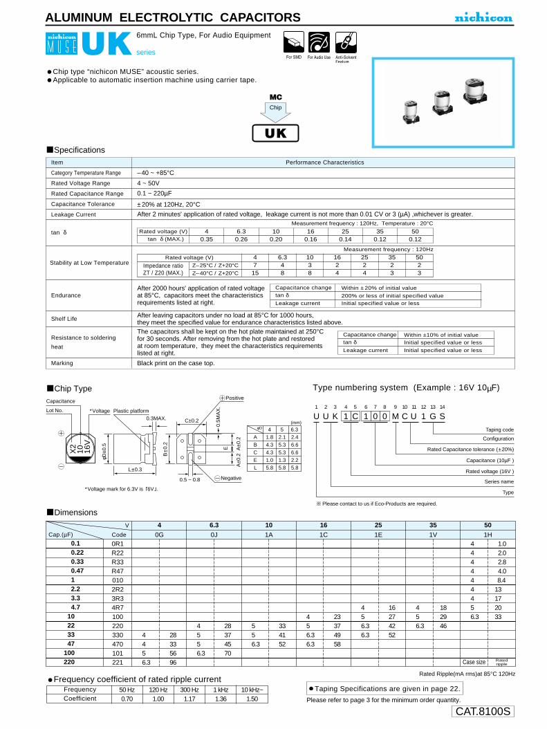
CAT.8100S
tan δ (MAX.)
0.10.220.330.4712.23.34.7
10223347
100220
0R1R22R33R470102R23R34R7100220330470101221
4456.3
28335696
4556.3
28374570
556.3
334152
456.36.3
23374958
456.36.3
16274252
456.3
182946
444444456.3
1.02.02.84.08.4
13172033
0G
Rated Ripple(mA rms)at 85°C 120Hz
40J
6.31A
101C
161E
251V
351H
50
U1
U2
K3
14
C5
16
07
08
M9
C10
U 11
112
G13
S14
Configuration
Taping code
Rated Capacitance tolerance (±20%)
Rated voltage (16V )
Capacitance (10µF )
Series name
Type∗Voltage mark for 6.3V is 6V .
(mm)
Capacitance
∗VoltageLot No.
X2
10 16V
Plastic platform0.3MAX.
L±0.3
φD±0
.5
B±0
.2
C±0.2
0.5M
AX
.
A±0
.2 A
±0.2
E
0.5 ~ 0.8
Positive
Negative
φD 4
A
B
C
E
1.8
4.3
4.3
1.0
2.1
5.3
5.3
1.3
2.4
6.6
6.6
2.2
L 5.8 5.8 5.8
5 6.3
Please contact to us if Eco-Products are required.
ALUMINUM ELECTROLYTIC CAPACITORS
Chip type “nichicon MUSE” acoustic series.Applicable to automatic insertion machine using carrier tape.
Chip Type
Specifications
Category Temperature Range
Rated Voltage Range
Rated Capacitance Range
Capacitance Tolerance
Leakage Current
tan δ
Stability at Low Temperature
Endurance
Shelf Life
Resistance to soldering
heat
Marking
Performance CharacteristicsItem
–40 ~ +85°C
4 ~ 50V
0.1 ~ 220µF
±20% at 120Hz, 20°C
After 2 minutes' application of rated voltage, leakage current is not more than 0.01 CV or 3 (µA) ,whichever is greater.
Black print on the case top.
Measurement frequency : 120Hz, Temperature : 20°C
Capacitance change
Leakage current
After 2000 hours' application of rated voltage at 85°C, capacitors meet the characteristics requirements listed at right.
After leaving capacitors under no load at 85°C for 1000 hours, they meet the specified value for endurance characteristics listed above.
tan δWithin ±20% of initial value
200% or less of initial specified valueInitial specified value or less
Rated voltage (V) 40.35
6.30.26
100.20
160.16
250.14
350.12
500.12
Measurement frequency : 120Hz
Z–25°C / Z+20°C
Z–40°C / Z+20°C
Rated voltage (V)
Impedance ratioZT / Z20 (MAX.)
4715
6.348
1038
1624
2524
3523
5023
Capacitance change
Leakage current
tan δWithin ±10% of initial value
Initial specified value or less
Initial specified value or less
Type numbering system (Example : 16V 10µF)
The capacitors shall be kept on the hot plate maintained at 250°Cfor 30 seconds. After removing from the hot plate and restoredat room temperature, they meet the characteristics requirementslisted at right.
UK series
6mmL Chip Type, For Audio Equipment
MC
UK
Chip
Taping Specifications are given in page 22.
Dimensions
Rated rippleCase size
CodeCap.(µF)
V
Please refer to page 3 for the minimum order quantity.
Frequency coefficient of rated ripple current
CoefficientFrequency 50 Hz 120 Hz 300 Hz 1 kHz 10 kHz~
0.70 1.00 1.17 1.36 1.50

CAT.8100S
nic
hic
on
330
µFUN
50
VBP
H96
36
φ D
±0.5
L±0.5
H±0.1
12.54.013.616.08.02.5
φDABCEH
16.4.517.119.510.53.75
18.5.019.121.511.53.75
20.5.021.123.513.53.75
B±0.2
B±0
.2
C±0
.2
A±0
.2A
±0.2
E
Trade mark VoltagePlastic platform
Series
Capacitance
Lot No.
Pressurerelief vent
(mm)
U1
U2
N3
14
H5
36
37
18
M9
N10
R11
112 13 14
Configuration
Package code
Taping
Tray
MS
ZD
Capacitance Tolerance(±20%)
Rated Capacitance(330µF)
Rated voltage(50V)
Series name
Type
φD
12.5 ~ 18
20
Code
NR
RR
22
33
47
100
220
330
470
1000
2200
3300
220
330
470
101
221
331
471
102
222
332
12.5 × 13.5
12.5 × 16
18 × 16.516 × 21.518 × 21.5
270
500
740740920
12.5 × 13.5
16 × 16.5
18 × 21.5
340
600
830
12.5 × 13.5
16 × 16.5
18 × 16.516 × 21.5
310
420
670670
12.5 × 13.5
16 × 16.5
16 × 16.5
18 × 21.5
12.5 × 13.5
16 × 16.5
18 × 16.516 × 21.518 × 21.5
12.5 × 13.5
12.5 × 16
18 × 16.516 × 21.518 × 21.5
20 × 21.5
12.5 × 13.5
16 × 16.5
18 × 21.5
20 × 21.5
12.5 × 13.5
12.5 × 16
16 × 16.5
18 × 21.5
Case size
270
370
490
780
180
330
450450590
130
230
400400540
640
140
270
440
590
ALUMINUM ELECTROLYTIC CAPACITORS
Endurance
tan δ
Stability at Low Temperature 5 4 3 2 2 2 2 2
Item
After 2000 hours' application of rated voltage at 105°C with thepolarity inverted every 250 hours, capacitors meet the characteristicrequirements listed at right.
10 8 6 4 3 3 3 3
6.3 10 16 25 35 50 63 100 120Hz
For capacitance of more than 1000µF, add 0.02 for every increase of 1000µF.
Z–25°C / Z+20°C
Z–40°C / Z+20°C
Rated voltage (V)
0.26 0.22 0.18 0.16 0.14 0.12 0.10 0.09 20°C
–55 ~ +105°C
6.3 ~ 100V
22 ~ 3300µF
±20% at 120Hz, 20°C
Rated voltage (V)
Impedance ratio
ZT / Z20 (MAX.)
After leaving capacitors under no load at 105°C for 1000 hours, they meet the specified
value for endurance characteristics listed above.
Black print on the case top.
After 1 minutes' application of rated voltage, leakage current is not more than 0.03CV or 4 (µA), whichever is greater.
tan δ (MAX)
6.3 10 16 25 35 50 63 100 120Hz
Category Temperature Range
Rated Voltage Range
Rated Capacitance Range
Capacitance Tolerance
Leakage Current
Shelf Life
Marking
Within ±20% of initial value200% or less of initial specified valueInitial specified value or less
Capacitance change
Leakage current
tan δ
Performance Characteristics
Specifications
UN series
Chip Type, Bi-Polarized, Higher Capacitance Range
Chip Type,higher capacitance in larger case sizes (φ12.5, φ16, φ18, φ20) Designed for surface mounting on high density PC board.Bi-polarized series for operations over wide temperature range of –55 ~ +105°C.Applicable to automatic mounting machine using carrier tape and tray.
Type numbering system (Example : 50V 330µF)
Dimensions6.3 10 16 25 35 50 63 100
0J 1A 1C 1E 1V 1H 1J 2ACap. Code(µF)
V
RatedRipple
Chip Type
UN Bi-polarized UJ
100
150
180
310
In this case, 6 will be put at 12th digit of type numbering system, " " Rated Ripple (mA rms) at 105°C 120Hz
D × L (mm)
Taping Specifications are given in page 22.Please refer to page 3 for the minimum order quantity.
Frequency coefficient of rated ripple currentCap.(µF)
00 ~ 470100 ~ 470
50 Hz 120 Hz 300 Hz 1 kHz 10 kHz~0.75 1.00 1.35 1.57 2.000.80 1.00 1.23 1.34 1.50
1000 ~ 3300 0.85 1.00 1.10 1.13 1.15
Frequency

CAT.8100S
ALUMINUM ELECTROLYTIC CAPACITORS
U1
U2
P3
14
C5
16
07
08
M9
C10
R11
112
G13
S14
Capacitance tolerance (±20%)
Configuration
Taping code
Rated Capacitance (10µF)
Rated voltage (16V)
Series name
Type
Voltage mark for 6.3V is 6V
Voltage
Capacitance
105°C Marking
Lot No.
X2P
10 16V
Plastic platform0.3 MAX.
L±0.3
φD±0
.5
B±0
.2
C±0.2
0.5
MA
X.
A±0
.2
A±0
.2
E
0.5 ~ 0.8
φD
A
B
C
E
1.8
4.3
4.3
1.0
2.1
5.3
5.3
1.3
2.4
6.6
6.6
2.2
L 5.8 5.8 5.8
4 5(mm)
6.3
UP series
6mmL Chip Type, Bi-Polarized
Chip type, bi-polarized withstanding high temperature range up to +105°C.Designed for surface mounting on high density PC board.Applicable to automatic mounting machine using carrier tape.
Chip Type
Dimensions
Type numbering system (Example : 16V 10µF)
Specifications
Category Temperature Range
Rated Voltage Range
Rated Capacitance Range
Capacitance Tolerance
Leakage Current
tan δ
Stability at Low Temperature
Endurance
Resistance to solderingheat
Shelf Life
Marking
Performance CharacteristicsItem
–55 ~ +105°C
6.3 ~ 50V
0.1 ~ 47µF
±20% at 120Hz, 20°C
After 2 minutes' application of rated voltage, leakage current is not more than 0.05 CV or 10 (µA), whichever is greater.
Black print on the case top.
After leaving capacitors under no load at 105°C for 1000 hours, they meet the specified value for endurance characteristics listed above.
UP
WP
UT
Measurement frequency : 120Hz, Temperature : 20°C
Measurement frequency : 120Hz
Rated voltage (V)tan δ (MAX.)
6.30.24
100.20
160.17
250.17
350.15
500.15
Z–25°C / Z+20°C
Z–40°C / Z+20°C
Rated voltage (V)
Impedance ratioZT / Z20 (MAX.)
6.348
1036
1624
2524
3523
5023
Rated Ripple (mA rms) at 105°C 120Hz
0.10.220.330.4712.23.34.7
10223347
0R1R22R33R470102R23R34R7100220330470
56.36.3
283745
46.36.3
173341
456.36.3
12233749
556.3
121627
4556.3
8.4161829
44444556.3
Case size
1.02.02.84.08.4
131720
0J6.3
1A10
1C16
1E25
1V35
1H50V
CodeCap.(µF)
Capacitance change
Leakage current
After 1000 hours' application of ratedvoltage at 105°C with the polarity invertedevery 250 hours, capacitors meet thecharacteristic requirements listed at right.
tan δWithin ±20% of initial value200% or less of initial specified valueInitial specified value or less
The capacitors shall be kept on the hot plate maintained at 250°Cfor 30 seconds. After removing from the hot plate and restored at room temperature, they meet the characteristic requirementslisted at right.
Capacitance change
Leakage current
tan δWithin ±10% of initial valueInitial specified value or lessInitial specified value or less
Bi-polarized
Ratedripple
Smaller
Please refer to page 3 for the minimum order quantity.
Taping Specifications are given in page 22.Frequency coefficient of rated ripple current
CoefficientFrequency 50 Hz 120 Hz 300 Hz 1 kHz 10 kHz~
0.70 1.00 1.17 1.36 1.50
• The lead-free product is also available upon request.In this case, will be put at 11th digit of type numbering system.L

CAT.8100S
Capacitance
Lot No.
Plastic platform0.3MAX.
φD±0
.5
B±0
.2
A±0
.2A
±0.2
C±0.2
0.5M
AX
.E
H
Positive
Negative
Voltage mark for 6.3V is 6V . In case of marking for φ3 units, "V" for rated voltage is omitted.
L±0.3
2Voltage
Trade mark N2
100
10V1
1 Size φ8 × 6.2 only2
H
Plastic platform0.3MAX.
φD±0
.5
B±0
.2
A±0
.2A
±0.2
C±0.2
0.5M
AX
.E
Positive
NegativeL±0.5
Voltage
CapacitanceLot No.
Trade mark
N2
100
35V
Pressure relief vent
(mm)
ABCELH
6.3 × 5.8
2.46.66.62.25.8
0.5 ~ 0.8
6.3 × 7.7
2.46.66.62.27.7
0.5 ~ 0.8
8 × 6.2
3.38.38.32.36.2
0.5 ~ 0.8
8 × 10
2.98.38.33.110
0.8 ~ 1.1
10 × 10
3.210.310.34.510
0.8 ~ 1.1
D × L
U1
U2
R3
14
A5
16
07
18
M9
C10
R11
112
G13
S14
Configuration
Package code
Case dia. code
Capacitance tolerance (±20%)
Rated Capacitance (100µF)
Rated voltage (10V)
Series name
Type
D × L
6.3 × 5.8
8 × 6.2
8 × 10
10 × 10
Code
CR
BR
6.3 × 7.7 CR
NR
NR
UR series
Chip Type, High CV
Chip type, higher capacitance in larger case sizes.Designed for surface mounting on high density PC board.Applicable to automatic mounting machine using carrier tape.
Chip Type
(φ6.3, φ8 × 6.2)
(φ8 × 10, φ10 × 10)
Specifications
Category Temperature Range
Rated Voltage Range
Rated Capacitance Range
Capacitance Tolerance
Leakage Current
tan δ
Stability at Low Temperature
Endurance
Shelf Life
Resistance to soldering
heat
Marking
Performance CharacteristicsItem
–40 ~ +85°C4 ~ 100V3.3 ~ 1500µF±20% at 120Hz, 20°CAfter 1 minute's application of rated voltage, leakage current is not more than 0.03CV (µA) .
Black print on the case top.
After leaving capacitors under no load at 85°C for 1000 hours, they meet the specifiedvalue for endurance characteristics listed above.
Type numbering system (Example : 10V 100µF)
The capacitors shall be kept on the hot plate maintained at 250°C,for 30 seconds. After removing from the hot plate and restoredat room temperature, they meet the characteristic requirementslisted at right.
UR
WX
After 2000 hours' application of rated voltage at 85°C, capacitors meet the characteristic requirements listed at right.
Capacitance change
Leakage current
tan δWithin ±20% of initial value
Initial specified value or less200% or less of initial specified value
Z–25°C / Z+20°C
Z–40°C / Z+20°C
Rated voltage (V)
Impedance ratioZT / Z20 (MAX.)
10023
6323
5023
3523
2524
1636
1048
6.3510
4715
Measurement frequency: 120Hz
Rated voltage (V)tan δ (MAX.)
500.12
630.12
1000.12
350.14
250.16
160.20
100.24
6.30.28
Measurement frequency : 120Hz, Temperature : 20°C
Capacitance change
Leakage current
tan δWithin ±10% of initial value
Initial specified value or lessInitial specified value or less
HigherC/V
40.35
ALUMINUM ELECTROLYTIC CAPACITORS
Dimension table in next page.
• The lead-free product is also available upon request.In this case, will be put at 11th digit of type numbering system.
Size φ8 × 6.2, will be put at 10th and 11th digit of type numbering system.CLL
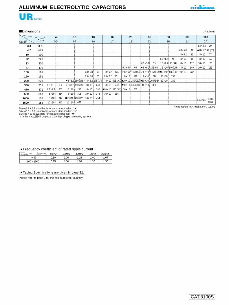
CAT.8100S
UR series
D × L (mm)
Rated Ripple (mA rms) at 85°C 120Hz
Taping Specifications are given in page 22.
Dimensions
Frequency coefficient of rated ripple current
00 ~ 47V100 ~ 1500
50 Hz 120 Hz 300 Hz 1 kHz 10 kHz~0.80 1.00 1.15 1.40 1.670.85 1.00 1.08 1.20 1.30
Cap.(µF)Frequency
Please refer to page 3 for the minimum order quantity.
Size φ6.3 × 5.8 is available for capacitors marked. " " Size φ6.3 × 7.7 is available for capacitors marked. " " Size φ8 × 10 is available for capacitors marked. " "
In this case, 6 will be put at 12th digit of type numbering system.
ALUMINUM ELECTROLYTIC CAPACITORS
3.3
4.7
10
22
33
47
100
150
220
330
470
680
1000
1500
3R3
4R7
100
220
330
470
101
151
221
331
471
681
102
152
6.3 × 5.8
6.3 × 7.7
8 × 10.
8 × 10.
10 × 10.
152
200
284
344
347
160 (143)
190 (188)
265
318
400 (372)
489
8 × 6.2
8 × 6.2
8 × 10.
8 × 10.
10 × 10.
10 × 10.
70
85
175 (173)
240
290
374
454
6.3 × 5.8
6.3 × 5.8
8 × 6.2
8 × 10.
8 × 10.
10 × 10.
10 × 10.
125
151
215 (162)
270
330 (307)
396
8 × 6.2
6.3 × 7.7
8 × 10.
8 × 10.
10 × 10.
10 × 10.
65
145 (143)
192
250 (232)
305 (284)
393
6.3 × 5.8
8 × 6.2
8 × 10.
10 × 10.
10 × 10.
10 × 10.
55
105 (94)
175 (132)
214
265 (246)
324
6.3 × 5.8
8 × 6.2
8 × 10.
8 × 10.
10 × 10.
10 × 10.
35
1V
50
1H
45
95 (94)
140 (105)
195 (181)
238
289
6.3 × 5.8
8 × 6.2
8 × 10.
10 × 10.
10 × 10.
10 × 10.
63
1J
31
46
96
117
140
232
6.3 × 5.8
8 × 6.2
8 × 10.
8 × 10.
8 × 10.
10 × 10.
29
40 (35)
77
100
130
155
6.3 × 5.8
8 × 6.2
8 × 10.
8 × 10.
10 × 10.
10 × 10.
100
2A
25
1E
16
1C
10
1A
6.3
0J
4
0GCap.(µF)
VCode
Case size Ratedripple

CAT.8100S
ALUMINUM ELECTROLYTIC CAPACITORS
Voltage
Capacitance
105°C Marking
Lot No.
X2P
10 16V
Plastic platform0.3MAX.
L±0.3
φD±0
.5
B±0
.2
C±0.2
0.5M
AX
.
A±0
.2
A±0
.2
E
Positive
Negative
AB
CE
L
4
1.8
4.3
4.3
1.0
5.8
5
2.1
5.3
5.3
1.3
5.8
6.3
2.4
6.6
6.6
2.2
5.8
0.5 ~ 0.8
(mm)φD
Voltage mark for 6.3V is 6V .
U1
U2
T3
14
C5
16
07
08
M9
C10
R11
112
G13
S14
Configuration
Taping code
Capacitance tolerance (±20%)
Rated voltage (16V)
Rated Capacitance (10µF)
Series name
Type
UT series
6mmL Chip Type , Wide Temperature Range
Chip type with load life 2000 hours at +105°C.Designed for surface mounting on high density PC board.Applicable to automatic mounting machine using carrier tape.
Chip Type
Specifications
Category Temperature Range
Rated Voltage Range
Rated Capacitance Range
Capacitance Tolerance
Leakage Current
tan δ
Stability at Low Temperature
Endurance
Shelf Life
Resistance to solderingheat
Marking
Performance CharacteristicsItem
–55 ~ +105°C
4 ~ 50V
0.1 ~ 100µF
±20% at 120Hz, 20°C
After 2 minutes' application of rated voltage, leakage current is not more than 0.01 CV or 3 (µA) , whichever is greater.
Black print on the case top.
Measurement frequency :120Hz, Temperature : 20°C
After 2000 hours' application of rated voltageat 105°C , capacitors meet the characteristicrequirements listed at right.
After leaving capacitors under no load at 105°C for 1000 hours,they meet the specified value for endurance characteristics listed above.
Type numbering system (Example : 16V 10µF)
Dimensions
Rated Ripple (mA rms) at 105°C 120Hz
Rated voltage (V)tan δ (MAX.)
40.37
500.12
350.13
250.16
160.20
100.24
6.30.28
Measurement frequency :120Hz
Z–25°C / Z+20°C
Z–40°C / Z+20°C
Rated voltage (V)
Impedance ratioZT / Z20 (MAX.)
4612
6.338
1035
1624
2523
3523
5023
0.10.220.330.4712.23.34.7
10223347
100
0R1R22R33R470102R23R34R7100220330470101
4556.3
22303660
0G
40J
6.31A
101C
161E
251V
351H
50
4556.3
22303660
556.36.3
27354660
456.36.3
18304050
456.36.3
13233848
456.3
152542
444444456.3
Case size
1.02.63.23.86.2
11141930
Allowableripple
Cap.(µF)
V
Code
The capacitors shall be kept on the hot plate maintained at 250°Cfor 30 seconds. After removing from the hot plate and restored at room temperature, they meet the characteristic requirementslisted at right.
tan δ
Capacitance
change
200% or less of initial specified valueLeakage current Initial specified value or less
Within ±25% of initial value (16V or less) Within ±20% of initial value (25V or more)
Capacitance change
Leakage current
tan δWithin ±10% of initial value
Initial specified value or lessInitial specified value or less
Ratedripple
Please refer to page 3 for the minimum order quantity.
Taping Specifications are given in page 22.Frequency coefficient of rated ripple current
CoefficientFrequency 50 Hz 120 Hz 300 Hz 1 kHz 10 kHz~
0.70 1.00 1.17 1.36 1.50
• The lead-free product is also available upon request.In this case, will be put at 11th digit of type numbering system.L
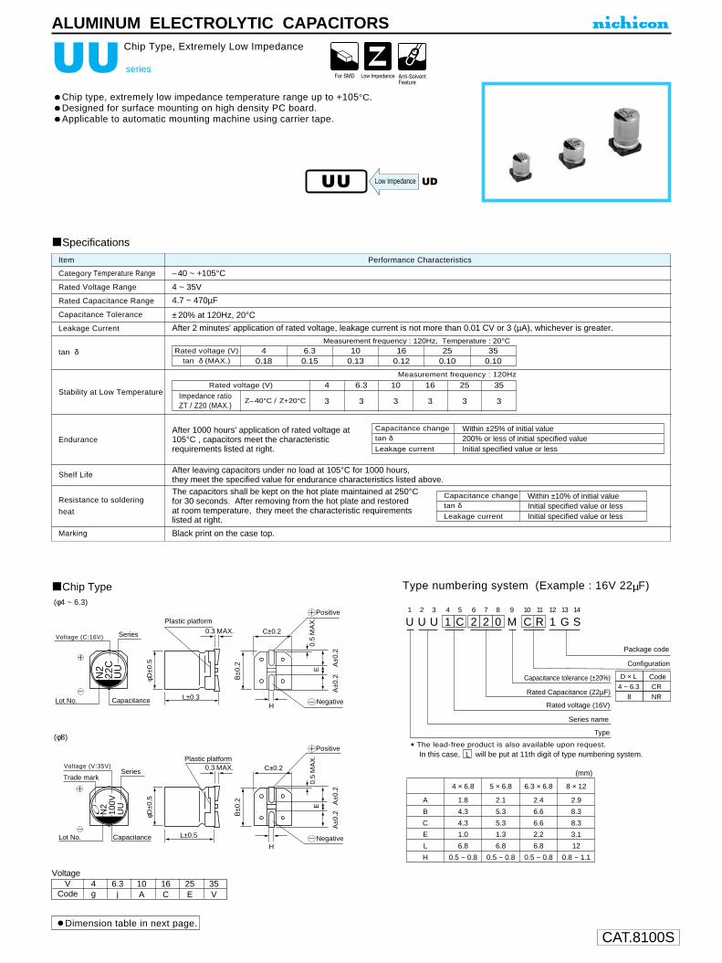
CAT.8100S
ALUMINUM ELECTROLYTIC CAPACITORS
N2
22C
UU
N2
100V
UU
0.3 MAX.
φD±0
.5
B±0
.2
A±0
.2A
±0.2
C±0.2
0.5
MA
X.
E
H
H
0.3 MAX.
φD±0
.5
B±0
.2
A±0
.2A
±0.2
C±0.2
0.5
MA
X.
E
L±0.3
L±0.5
Series
CapacitanceLot No.
Lot No. Capacitance
Plastic platform
Plastic platform
SeriesTrade mark
Voltage (C:16V)
Voltage (V:35V)
Negative
Positive
Negative
Positive
U1
U2
U3
14
C5
26
27
08
M9
C10
R11
112
G13
S14
D × L
4 ~ 6.3
8
CR
NR
Configuration
Package code
Capacitance tolerance (±20%)
Rated Capacitance (22µF)
Rated voltage (16V)
Series name
Type
Code
(mm)
A
B
C
E
L
H
4 × 6.8
1.8
4.3
4.3
1.0
6.8
0.5 ~ 0.8
5 × 6.8
2.1
5.3
5.3
1.3
6.8
0.5 ~ 0.8
6.3 × 6.8
2.4
6.6
6.6
2.2
6.8
0.5 ~ 0.8
8 × 12
2.9
8.3
8.3
3.1
12
0.8 ~ 1.1
UU series
Chip Type, Extremely Low Impedance
Chip type, extremely low impedance temperature range up to +105°C.Designed for surface mounting on high density PC board.Applicable to automatic mounting machine using carrier tape.
Chip Type
Specifications
Category Temperature Range
Rated Voltage Range
Rated Capacitance Range
Capacitance Tolerance
Leakage Current
tan δ
Stability at Low Temperature
Endurance
Shelf Life
Resistance to soldering
heat
Marking
Performance CharacteristicsItem
–40 ~ +105°C
4 ~ 35V
4.7 ~ 470µF
±20% at 120Hz, 20°C
After 2 minutes' application of rated voltage, leakage current is not more than 0.01 CV or 3 (µA), whichever is greater.
Black print on the case top.
After 1000 hours' application of rated voltage at105°C , capacitors meet the characteristicrequirements listed at right.
After leaving capacitors under no load at 105°C for 1000 hours,they meet the specified value for endurance characteristics listed above.
Type numbering system (Example : 16V 22µF)
Measurement frequency : 120Hz, Temperature : 20°C
Measurement frequency : 120Hz
Z–40°C / Z+20°C
Rated voltage (V)
Impedance ratioZT / Z20 (MAX.)
16
3
10
3
4
3
6.3
3
25
3
35
3
Rated voltage (V)tan δ (MAX.)
350.10
250.10
160.12
100.13
40.18
6.30.15
Within ±25% of initial value
Initial specified value or less200% or less of initial specified value
Capacitance changetan δLeakage current
Capacitance change
Leakage current
tan δWithin ±10% of initial value
Initial specified value or lessInitial specified value or less
The capacitors shall be kept on the hot plate maintained at 250°Cfor 30 seconds. After removing from the hot plate and restored at room temperature, they meet the characteristic requirementslisted at right.
(φ4 ~ 6.3)
(φ8)
Dimension table in next page.
VoltageV 4 6.3 10 16 25 35
Code g j A C E V
Low Impedance
• The lead-free product is also available upon request.In this case, will be put at 11th digit of type numbering system.L
UU UD
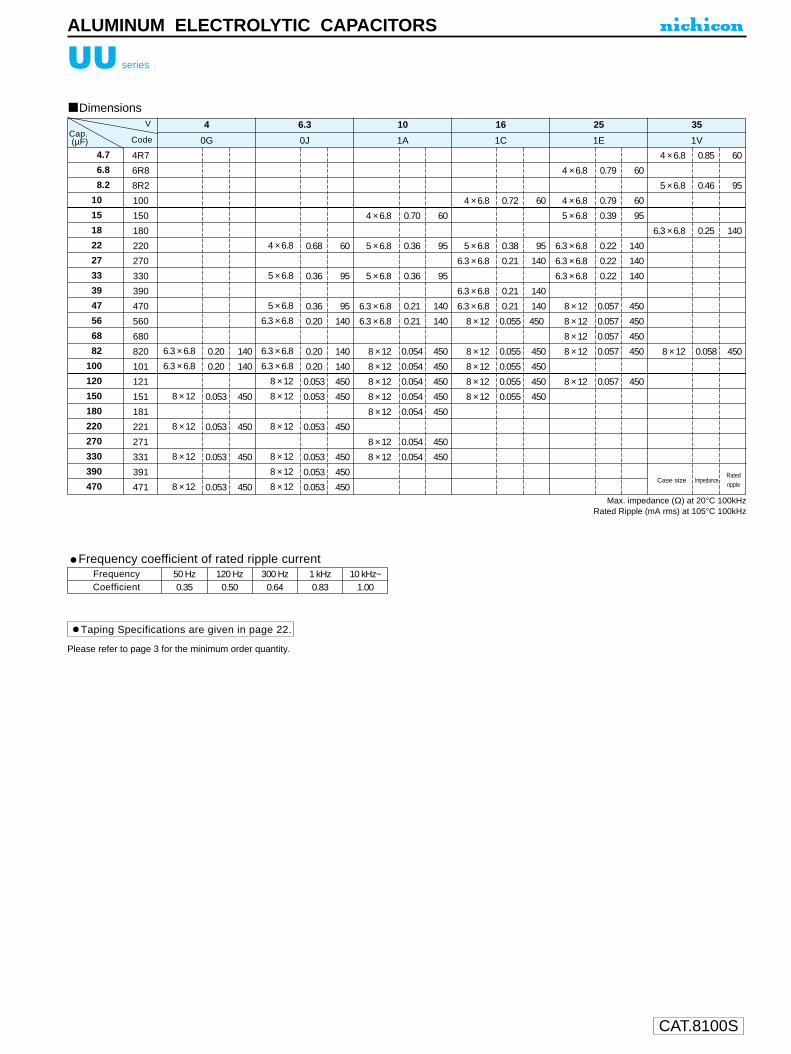
CAT.8100S
ALUMINUM ELECTROLYTIC CAPACITORS
UU series
Please refer to page 3 for the minimum order quantity.
Taping Specifications are given in page 22.
Frequency coefficient of rated ripple current
CoefficientFrequency 50 Hz 120 Hz 300 Hz 1 kHz 10 kHz~
0.35 0.50 0.64 0.83 1.00
4.7
6.8
8.2
10
15
18
22
27
33
39
47
56
68
82
100
120
150
180
220
270
330
390
470
4R7
6R8
8R2
100
150
180
220
270
330
390
470
560
680
820
101
121
151
181
221
271
331
391
471
6.3 × 6.8
6.3 × 6.8
8 × 12
8 × 12
8 × 12
8 × 12
0.20
0.20
0.053
0.053
0.053
0.053
140
140
450
450
450
450
1V
35
0G
4
0J
6.3
1A
10
1C
16
1E
25
4 × 6.8
5 × 6.8
5 × 6.8
6.3 × 6.8
6.3 × 6.8
6.3 × 6.8
8 × 12
8 × 12
8 × 12
8 × 12
8 × 12
8 × 12
0.68
0.36
0.36
0.20
0.20
0.20
0.053
0.053
0.053
0.053
0.053
0.053
60
95
95
140
140
140
450
450
450
450
450
450
4 × 6.8
5 × 6.8
5 × 6.8
6.3 × 6.8
6.3 × 6.8
8 × 12
8 × 12
8 × 12
8 × 12
8 × 12
8 × 12
8 × 12
0.70
0.36
0.36
0.21
0.21
0.054
0.054
0.054
0.054
0.054
0.054
0.054
60
95
95
140
140
450
450
450
450
450
450
450
4 × 6.8
5 × 6.8
6.3 × 6.8
6.3 × 6.8
6.3 × 6.8
8 × 12
8 × 12
8 × 12
8 × 12
8 × 12
0.72
0.38
0.21
0.21
0.21
0.055
0.055
0.055
0.055
0.055
60
95
140
140
140
450
450
450
450
450
4 × 6.8
4 × 6.8
5 × 6.8
6.3 × 6.8
6.3 × 6.8
6.3 × 6.8
8 × 12
8 × 12
8 × 12
8 × 12
8 × 12
0.79
0.79
0.39
0.22
0.22
0.22
0.057
0.057
0.057
0.057
0.057
60
60
95
140
140
140
450
450
450
450
450
4 × 6.8
5 × 6.8
6.3 × 6.8
8 × 12
0.85
0.46
0.25
0.058
60
95
140
450
V
CodeCap.(µF)
ImpedanceCase sizeRatedripple
Dimensions
Max. impedance (Ω) at 20°C 100kHzRated Ripple (mA rms) at 105°C 100kHz

CAT.8100S
ALUMINUM ELECTROLYTIC CAPACITORS
Voltage
Capacitance
105°C Marking
Lot No.
X2P
10 16V
Plastic platform0.3MAX.
L±0.3
φD±0
.5
B±0
.2
C±0.2
0.5M
AX
.
A±0
.2
A±0
.2
E
Positive
Negative0.5 ~ 0.8
(mm)φD
A
B
C
E
1.8
4.3
4.3
1.0
2.1
5.3
5.3
1.3
2.4
6.6
6.6
2.2
L 5.8 5.8 5.8
4 5 6.3
Voltage mark for 6.3V is 6V .
U1
U2
V3
14
C5
16
07
08
M9
F10
R11
112
G13
S14
Configuration
Taping code
Capacitance tolerance (±20%)
Rated voltage (16V)
Rated Capacitance (10µF)
Series name
Type
UV series
6mmL Chip Type, Long Life Assurance
Chip type with load life of 5000 hours at +105°C.Designed for surface mounting on high density PC board.Applicable to automatic insertion machine using carrier tape.
Chip Type
Specifications
Category Temperature Range
Rated Voltage Range
Rated Capacitance Range
Capacitance Tolerance
Leakage Current
tan δ
Stability at Low Temperature
Endurance
Shelf Life
Resistance to soldering
heat
Marking
Performance CharacteristicsItem
–40 ~ +105°C
4 ~ 50V
0.1 ~ 100µF
±20% at 120Hz, 20°C
After 2 minutes' application of rated voltage, leakage current is not more than 0.01 CV or 3 (µA) , whichever is greater.
Black print on the case top.
After 5000 hours' application of rated voltageat 105°C , capacitors meet the characteristicrequirements listed at right.
After leaving capacitors under no load at 105°C for 1000 hours,they meet the specified value for endurance characteristics listed above.
Type numbering system (Example : 16V 10µF)
Dimensions
Rated Ripple (mA rms) at 105°C 120Hz
UVLong LifeUT
Measurement frequency : 120Hz, Temperature : 20°C
Measurement frequency : 120Hz
0.10.220.330.4712.23.34.7
10223347
100
0R1R22R33R470102R23R34R7100220330470101
4556.3
22303660
0G
40J
6.31A
101C
161E
251V
351H
50
4556.3
22303660
556.3
273546
456.36.3
18304050
456.36.3
13233848
456.3
152542
444444456.3
Case size
1.02.63.23.86.2
11141930
Allowableripple
V
CodeCap.(µF)
Z–25°C / Z+20°C
Z–40°C / Z+20°C
Rated voltage (V)
Impedance ratioZT / Z20 (MAX.)
1037
6.3410
4814
1625
2523
3523
5023
Rated voltage (V)tan δ (MAX.)
500.12
350.13
250.16
160.20
100.24
6.30.28
40.37
Within ±30% of initial value
Initial specified value or less300% or less of initial specified value
Capacitance changetan δLeakage current
Capacitance change
Leakage current
tan δWithin ±10% of initial value
Initial specified value or lessInitial specified value or less
The capacitors shall be kept on the hot plate maintained at 250°Cfor 30 seconds. After removing from the hot plate and restored at room temperature, they meet the characteristic requirementslisted at right.
Ratedripple
Please refer to page 3 for the minimum order quantity.
Taping Specifications are given in page 22.
Frequency coefficient of rated ripple current
CoefficientFrequency 50 Hz 120 Hz 300 Hz 1 kHz 10 kHz~
0.70 1.00 1.17 1.36 1.50
• The lead-free product is also available upon request.In this case, will be put at 10th and 11th digit of type numbering system.CL
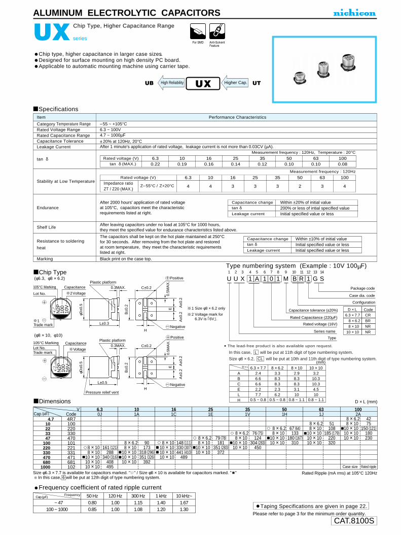
CAT.8100S
U1
U2
X3
14
A5
16
07
18
M9
B10
R11
112
G13
S14
D × L
8 × 6.2
8 × 10
BR
6.3 × 7.7 CR
NR
10 × 10 NR
Configuration
Package code
Case dia. code
Capacitance tolerance (±20%)
Rated Capacitance (220µF)
Rated voltage (16V)
Series name
Type
Code
(mm)
ABCELH
6.3 × 7.72.46.66.62.27.7
0.5 ~ 0.8
8 × 6.23.38.38.32.36.2
0.5 ~ 0.8
8 × 102.98.38.33.110
0.8 ~ 1.1
10 × 103.210.310.34.510
0.8 ~ 1.1
D × L
ALUMINUM ELECTROLYTIC CAPACITORS
UX series
Chip Type, Higher Capacitance Range
Chip type, higher capacitance in larger case sizes..Designed for surface mounting on high density PC board.Applicable to automatic mounting machine using carrier tape.
Chip Type(φ6.3, φ8 × 6.2)
(φ8 × 10, φ10)
Specifications
Category Temperature RangeRated Voltage RangeRated Capacitance RangeCapacitance ToleranceLeakage Current
tan δ
Stability at Low Temperature
Endurance
Shelf Life
Resistance to soldering
heat
Marking
Performance CharacteristicsItem
–55 ~ +105°C6.3 ~ 100V4.7 ~ 1000µF
±20% at 120Hz, 20°CAfter 1 minute's application of rated voltage, leakage current is not more than 0.03CV (µA).
Black print on the case top.
Measurement frequency : 120Hz
After 2000 hours' application of rated voltage at 105°C, capacitors meet the characteristic requirements listed at right.
After leaving capacitors under no load at 105°C for 1000 hours, they meet the specified value for endurance characteristics listed above.
Z–55°C / Z+20°C
Rated voltage (V)
Impedance ratioZT / Z20 (MAX.)
100
4
63
3
50
2
35
3
25
3
16
3
10
4
6.3
4
UX UT
Type numbering system (Example : 10V 100µF)
The capacitors shall be kept on the hot plate maintained at 250°Cfor 30 seconds. After removing from the hot plate and restoredat room temperature, they meet the characteristic requirementslisted at right.
D × L (mm)
Rated Ripple (mA rms) at 105°C 120Hz
Taping Specifications are given in page 22.
Dimensions
Frequency coefficient of rated ripple currentCap.(µF)
00 ~ 470100 ~ 1000
50 Hz 120 Hz 300 Hz 1 kHz 10 kHz~0.80 1.00 1.15 1.40 1.670.85 1.00 1.08 1.20 1.30
Frequency
Rated voltage (V)tan δ (MAX.)
6.30.22
100.19
160.16
250.14
350.12
500.10
630.10
1000.08
Measurement frequency : 120Hz, Temperature : 20°C
Capacitance change
Leakage current
tan δWithin ±10% of initial value
Initial specified value or lessInitial specified value or less
Capacitance change
Leakage current
tan δWithin ±20% of initial value
Initial specified value or less200% or less of intial specified value
Higher Cap.UB High Reliability
Please refer to page 3 for the minimum order quantity.
Size φ6.3 × 7.7 is available for capacitors marked. " " / Size φ8 × 10 is available for capacitors marked. " " In this case, 6 will be put at 12th digit of type numbering system.
4.710223347
100220330470680
1000
4R7100220330470101221331471681102
8 × 108 × 10
10 × 1010 × 1010 × 10
161 (121)288
340 (316)408495
90173
318 (296)351 (326)
392
8 × 6.28 × 10
10 × 1010 × 1010 × 10
148 (111)330 (307)441 (410)
489
8 × 1010 × 1010 × 1010 × 10
79 (78)181
351 (283)372
8 × 6.28 × 10
10 × 1010 × 10
76 (75)124
304 (283)450
8 × 6.28 × 10
10 × 1010 × 10
67 (64)133
180 (167)310
8 × 6.28 × 10
10 × 1010 × 10
351V
501H
51108
185 (179)220320
8 × 6.28 × 10
10 × 1010 × 1010 × 10
631J
4275
150 (121)180230
8 × 6.28 × 10
10 × 1010 × 1010 × 10
1002A
251E
161C
101A
6.30JCap.(µF)
VCode
Case size Rated ripple
2Voltage
Capacitance105°C Marking
Lot No.
Plastic platform0.3MAX.
φD±0
.5
B±0
.2
A±0
.2A
±0.2
C±0.2
0.5M
AX
.E
H
H
Positive
Negative
2 Voltage mark for 6.3V is 6V .
Plastic platform
Pressure relief vent
0.3MAX.
φD±0
.5
B±0
.2
A±0
.2A
±0.2
C±0.2
0.5M
AX
.E
Positive
Negative
L±0.3
L±0.5
Voltage
CapacitanceLot No.Trade mark
Trade mark
105°C Marking
N2P
100
16V
N2P
100
10V
1
1 Size φ8 × 6.2 only
• The lead-free product is also available upon request.
In this case, will be put at 11th digit of type numbering system.
Size φ8 × 6.2, will be put at 10th and 11th digit of type numbering system.CL
L

CAT.8100S
φD
P
φd
5
2.0
0.5
6.3
2.5
0.5
8
3.5
0.6
10
5.0
0.6
12.5
5.0
0.6
16
7.5
0.8
18
7.5
0.8
20 22
10.0 10.0
1.0 1.0
25
12.5
1.0
0.5 0.5 0.5 0.5 0.5 0.5 0.5 0.5 1.0 1.0
P±0
.5
(φ6.3up)L+ MAX 15MIN 4MIN
φD+
M
AX
Pressurerelief vent
φd
(L 20) 1.5
(L 20) 2.0
Sleeve (P.E.T.)
U1
V2
K3
14
A5
36
37
18
M9
E10
D11
Configuration
Capacitance tolerance (±20%)
Rated Capacitance (330µF)
Rated voltage (10V)
Series name
Type
φ D
5
Pb free lead finishingPb free PET sleeve
DD
6.3 ED
8 · 10 PD
HD
Configuration
RD
12.5 ~ 18
20 ~ 25 Please contact to us if other configurations are required.
VK
VY
VR
Specifications
Category Temperature Range
Rated Voltage Range
Rated Capacitance Range
Capacitance Tolerance
Leakage Current
tan δ
Stability at Low Temperature
Endurance
Shelf Life
Marking
Performance CharacteristicsItem
–40 ~ +85˚C (6.3V ~ 400V), –25˚C ~ +85˚C (450V)
6.3 ~ 450V
0.1 ~ 68000µF
±20% at 120Hz, 20˚C
Printed with white color letter on black sleeve.
After leaving capacitors under no load at 85˚C for 1000 hours, they meet the specified value forendurance characteristics listed above.
Rated voltage (V)
tan δ (MAX.)6.30.28
100.24
160.20
250.16
350.14
500.12
630.10
1000.08
160~2500.20
350~4500.25
For capacitance of more than 1000µF, add 0.02 for every increase of 1000µF. Measurement frequency : 120Hz, Temperature : 20˚C
Measurement frequency : 120Hz
Z–25˚C / Z+20˚C
Z–40˚C / Z+20˚C
Rated voltage (V)
Impedance ratioZT / Z20 (MAX.)
6.3512
10410
1638
2525
3524
160~20034
50~10023
250~35048
400610
45015
After 2000 hours' application of rated voltage at 85˚C,capacitors meet the characteristic requirements listed at right.
Rated voltage (V) 6.3 ~ 100V 160 ~ 450VAfter 1 minute's application of rated voltage, leakage current is not more than 0.03CV or 4 (µA), whichever is greater.
After 2 minutes' application of rated voltage, leakage current is not more than 0.01CV or 3 (µA), whichever is greater.
After 1 minute's application of rated voltage,CV <= 1000 :1= 0.1CV+40µA or less
After 1 minute's application of rated voltage,CV>1000 :1= 0.04CV+100 (µA) or less
Leakage current
tan δCapacitance change
Initial specified value or less200% or less of initial specified valueWithin ±20% of initial value
The laminated case is also available upon request. Please refer to page 19, 20, 21 about the formed or taped product spec.Please refer to page 3 for the minimum order quantity.
Radial Lead Type Type numbering system (Example : 10V 330µF)
HighTem perature
Smaller
ALUMINUM ELECTROLYTIC CAPACITORS
VK series
Miniature Sized
One rank smaller case sizes than VR series.
Dimension table in next page.

CAT.8100S
D ×L (mm)
D ×L (mm)
Cap.(µF)
~ 68000100 ~ 47000
1000 ~ 680000.1 ~ 22000330 ~ 10000
6.3 ~ 100
V
160 ~ 450
50Hz 120Hz 300Hz 1 kHz 10kHz ~
0.75 1.00 1.35 1.57 2.000.80 1.00 1.23 1.34 1.500.85 1.00 1.10 1.13 1.150.80 1.00 1.25 1.40 1.600.90 1.00 1.10 1.13 1.15
Frequency
0.10.220.330.4712.23.34.7
1022334768
100220330470
10002200330047006800
100001500022000330004700068000
0R1R22R33R470102R23R34R7100220330470680101221331471102222332472682103153223333473683
8 × 11.510 × 1610 × 20
12.5 × 2012.5 × 25
16 × 2516 × 31.518 × 35.520 × 4022 × 5025 × 50
540890
119015501920235025503200350039004300
0J6.3
5 × 116.3 × 116.3 × 1110 × 12.510 × 16
12.5 × 2012.5 × 25
16 × 2516 × 31.516 × 35.518 × 4022 × 5025 × 50
220290350650990
14501800225025502880340045005000
1A10
6.3 × 116.3 × 11
8 × 11.510 × 12.510 × 20
12.5 × 2516 × 2516 × 2516 × 35.518 × 4022 × 4025 × 50
260320440700
10001700210022502710310038004800
1C16
5 × 116.3 × 11
8 × 11.510 × 12.510 × 16
12.5 × 2516 × 2516 × 2516 × 35.518 × 4022 × 5025 × 50
180280390550860
1550198022002600280038004500
1E25
5 × 116.3 × 116.3 × 11
8 × 11.510 × 12.510 × 16
12.5 × 2016 × 2516 × 31.516 × 35.518 × 4022 × 5025 × 50
130160210350490650
1150180021002500280037004300
1V35
5 × 115 × 115 × 115 × 115 × 115 × 115 × 115 × 115 × 115 × 115 × 11
6.3 × 116.3 × 11
8 × 11.510 × 12.510 × 1610 × 20
12.5 × 2516 × 31.518 × 35.520 × 4022 × 5025 × 50
1.32.94.36.2
172835406095
125155210260430590760
135019802500290035004000
1H50
5 × 116.3 × 116.3 × 11
8 × 11.58 × 11.5
10 × 1610 × 20
12.5 × 2016 × 2518 × 35.520 × 4022 × 5025 × 50
Case size
100140170220280490710900
13002300270034003900
1J
63
0.10.220.330.4712.23.34.7
1022334768
100220330470
100022003300
0R1R22R33R470102R23R34R7100220330470680101221331471102222332
5 × 115 × 115 × 115 × 115 × 115 × 115 × 115 × 115 × 11
6.3 × 118 × 11.58 × 11.5
10 × 12.510 × 16
12.5 × 2012.5 × 25
16 × 2518 × 35.522 × 5025 × 50
2.14.77
102130404570
130180200270340550760
1000135024002900
2A100
8 × 11.510 × 12.510 × 1610 × 20
12.5 × 2012.5 × 25
16 × 31.518 × 35.518 × 4025 × 50
80130180210350430580800
12001900
2C160
6.3 × 116.3 × 116.3 × 116.3 × 116.3 × 116.3 × 116.3 × 116.3 × 11
8 × 11.510 × 1610 × 20
12.5 × 2012.5 × 25
16 × 2516 × 35.518 × 4022 × 40
2.14.77
152233405080
150200270350450700950
1300
2D200
6.3 × 116.3 × 1110 × 12.510 × 2010 × 20
12.5 × 2016 × 2516 × 25
18 × 35.520 × 4022 × 50
4050
100150200270380440680
10001400
2E250
6.3 × 118 × 11.58 × 11.5
10 × 12.512.5 × 2012.5 × 25
16 × 2516 × 2518 × 35.522 × 5025 × 50
30435590
150240300400520760
1000
2V350
6.3 × 116.3 × 11
8 × 11.58 × 11.5
10 × 12.510 × 16
12.5 × 2516 × 2516 × 2516 × 31.518 × 35.522 × 50
122038486090
200240280340440650
2G400
8 × 11.510 × 12.510 × 12.510 × 20
12.5 × 2516 × 2516 × 31.518 × 35.518 × 4025 × 50
Case size
28404680
140180220260280350
2W
450
Rated Ripple (mA rms) at 85˚C 120Hz
VK series
ALUMINUM ELECTROLYTIC CAPACITORS
Dimensions
Cap.(µF)Code
V
Cap.(µF)Code
V
Frequency coefficient of rated ripple current
Ratedripple
Ratedripple

CAT.8100S
Pressurerelief vent
15MIN 4MIN
φd
φD+
0.5
MA
X
P±0
.5
(φ6.3up)L+ MAX
φD
P
φd
5
2.0
0.5
6.3
2.5
0.5
8
3.5
0.6
10
5.0
0.6
12.5
5.0
0.6
16
7.5
0.8
18
7.5
0.8
(L < 20) 1.5(L >= 20) 2.0
Sleeve (P.E.T.)
ALUMINUM ELECTROLYTIC CAPACITORS
VP series
Bi-Polarized
Standard bi-polarized series for entertainment electronics.
Radial Lead Type Type numbering system (Example : 10V 47µF)
U1
V2
P3
14
A5
46
77
08
M9
D10
D11
Configuration
Capacitance tolerance (± 20%)
Rated Capacitance (47µF)
Rated voltage (10V)
Series name
Type
φ D
5
Pb free lead finishingPb free PET sleeve
Sn-Pb lead finishingPVC sleeve contain Pb
DD DA
6.3 ED EA
8 · 10 PD PA
12.5 ~ 18 HD HA
Configuration
Please contact to us if other configurations are required.
Specifications
Category Temperature Range
Rated Voltage Range
Rated Capacitance Range
Capacitance Tolerance
Leakage Current
tan δ
Stability at Low Temperature
Endurance
Shelf Life
Marking
Performance CharacteristicsItem
–40 ~ +85°C
6.3 ~ 100V
0.47 ~ 6800µF
±20% at 120Hz, 20°C
After 5 minutes' application of rated voltage, leakage current is not more than 0.03CV or 3 (µA), whichever is greater.
Printed with white color letter on black sleeve.
For capacitance of more than 1000µF, add 0.02 for every increase of 1000µF. Measurement frequency : 120Hz, Temperature : 20°C
Measurement frequency : 120Hz
After 2000 hours' application of rated voltageat 85°C with the polarity inverted every 250hours,capacitors meet the characteristicrequirements listed at right.
After leaving capacitors under no load at 85°C for 1000 hours, they meet the specified value for endurance characteristics listed above.
Rated voltage (V)tan δ (MAX.)
6.30.26
100.24
160.22
250.20
350.16
500.14
630.12
1000.10
Z–25°C / Z+20°C
Z–40°C / Z+20°C
Rated voltage (V)
Impedance ratioZT / Z20 (MAX)
1038
1626
2525
3524
5024
6323
10023
VP
6.3410
Capacitance change
Leakage current
tan δWithin ±20% of initial value200% or less of initial specified valueInitial specified value or less
HighTemperature
ET
Please refer to page 19, 20, 21 about the formed or taped product spec.Please refer to page 3 for the minimum order quantity.
Dimension table in next page.

CAT.8100S
VP series
5 × 11
5 × 11
6.3 × 11
6.3 × 11
6.3 × 11
8 × 11.5
10 × 16
12.5 × 20
12.5 × 20
16 × 25
18 × 35.5
57
64
76
125
215
345
410
720
1280
1690
2160
5 × 11
5 × 11
5 × 11
5 × 11
5 × 11
6.3 × 11
8 × 11.5
8 × 11.5
10 × 12.5
10 × 20
12.5 × 25
16 × 25
16 × 31.5
14
21
34
39
47
71
135
220
240
425
720
Ratedripple
28
34
57
95
135
180
320
575
655
965
11
17
25
27
34
52
89
105
150
265
480
650
835
34
43
73
100
120
230
410
505
655
1140
42
57
70
95
160
275
375
485
855
1510
1980
5 × 11
5 × 11
5 × 11
6.3 × 11
8 × 11.5
10 × 16
10 × 16
12.5 × 20
16 × 25
16 × 31.5
18 × 35.5
0.47
1
2.2
3.3
4.7
10
22
33
47
100
220
330
470
1000
2200
3300
4700
6800
Dimensions
R47
010
2R2
3R3
4R7
100
220
330
470
101
221
331
471
102
222
332
472
682
5 × 11
5 × 11
6.3 × 11
8 × 11.5
8 × 11.5
10 × 12.5
10 × 20
12.5 × 25
16 × 25
16 × 31.5
18 × 35.5
64
76
125
215
265
370
650
1160
1570
2020
2600
0J
Rated Ripple (mA rms) at 85°C 120Hz
6.3
1A
10
1C
16
1E
25
1V
35
1H
50
1J 2A
63 100
5 × 11
5 × 11
5 × 11
6.3 × 11
8 × 11.5
10 × 12.5
10 × 16
10 × 20
12.5 × 25
16 × 31.5
18 × 35.5
5 × 11
5 × 11
6.3 × 11
8 × 11.5
8 × 11.5
10 × 16
12.5 × 20
12.5 × 20
12.5 × 25
16 × 31.5
5 × 11
6.3 × 11
6.3 × 11
8 × 11.5
10 × 12.5
10 × 16
12.5 × 20
16 × 25
16 × 31.5
18 × 35.5
D × L (mm)
5 × 11
6.3 × 11
6.3 × 11
6.3 × 11
8 × 11.5
10 × 16
12.5 × 20
12.5 × 20
16 × 25
18 × 35.5
42
65
80
95
160
305
450
540
950
1620
Case size
V
CodeCap. (µF)
ALUMINUM ELECTROLYTIC CAPACITORS
Frequency coefficient of rated ripple current
Cap.(µF)
0000 ~ 4700
0100 ~ 4700
1000 ~ 6800
50 Hz 120 Hz 300 Hz 1 kHz 10 kHz ~
0.75 1.00 1.35 1.57 2.00
0.80 1.00 1.23 1.34 1.50
0.85 1.00 1.10 1.13 1.15
Frequency

CAT.8100S
ALUMINUM ELECTROLYTIC CAPACITORS
VR series
Miniature Sized
One rank smaller case sizes than VX series.
Approved by Reliability Center for ElectronicComponent, Japan-Certification No. RCJ-03-22C
Radial Lead Type
Specifications
Type numbering system (Example : 10V 330µF)
Category Temperature Range
Rated Voltage Range
Rated Capacitance Range
Capacitance Tolerance
Leakage Current
tan δ
Stability at Low Temperature
Endurance
Shelf Life
Marking
Performance CharacteristicsItem
–40 ~ +85˚C (6.3V ~ 400V), –25˚C ~ +85˚C (450V)
6.3 ~ 450V
0.1 ~ 33000µF
±20% at 120Hz, 20˚C
Printed with white color letter on black sleeve.
After leaving capacitors under no load at 85˚C for 1000 hours, they meet the specified value forendurance characteristics listed above.
VR
Rated voltage (V)
tan δ (MAX.)6.30.28
100.24
160.20
250.16
350.14
500.12
630.10
1000.08
160 ~ 3150.20
350 ~ 4500.25
For capacitance of more than 1000µF, add 0.02 for every increase of 1000µF. Measurement frequency : 120Hz, Temperature : 20˚C
Measurement frequency : 120Hz
Z–25˚C / Z+20˚C
Z–40˚C / Z+20˚C
Rated voltage (V)
Impedance ratioZT / Z20 (MAX.)
6.3512
10410
1638
2525
3524
5023
6323
10023
160 ~ 20034
250 ~ 35048
400610
45015
After 2000 hours' application of rated voltage at 85˚C,capacitors meet the characteristic requirements listed at right.
U1
V2
R3
14
A5
36
37
18
M9
E10
D11 12
Configuration
Capacitance tolerance (±20%)
Rated Capacitance (330µF)
Rated voltage (10V)
Series name
Type
φ D
4
Pb free lead finishingPb free PET sleeve
Sn-Pb lead finishingPVC sleeve contain Pb
DD6 DA6
5 DD DA
6.3 ED EA
8 · 10 PD PA
12.5 ~ 18 HD HA
20 ~ 25 RD RA
Configuration
Please contact to us if other configurations are required.
Pressurerelief vent
15MIN 4MIN
φd
P±0
.5
(φ6.3up)
φD+
M
AX
L+ MAX
Sleeve (P.E.T.)
VZ
VK
φD
P
φd
4
1.5
0.45
5
2.0
0.5
6.3
2.5
0.5
8
3.5
0.6
10
5.0
0.6
12.5
5.0
0.6
16
7.5
0.8
18
7.5
0.8
20 22
10.0 10.0
1.0 1.0
25
12.5
1.0
0.5 0.5 0.5 0.5 0.5 0.5 0.5 0.5 0.5 1.0 1.0
(L 20) 1.5(L 20) 2.0
Rated voltage (V) 6.3 ~ 100V 160 ~ 450VAfter 1 minute's application of rated voltage, leakage current is not more than 0.03CV or 4 (µA), whichever is greater.
After 2 minutes' application of rated voltage, leakage current is not more than 0.01CV or 3 (µA), whichever is greater.
After 1 minute's application of rated voltage,CV <= 1000 :1= 0.1CV+40µA or less
After 1 minute's application of rated voltage,CV > 1000 :1= 0.04CV+100 (µA) or less
Leakage current
tan δCapacitance change
Initial specified value or less200% or less of initial specified valueWithin ±20% of initial value
HighTemperature
Please refer to page 19, 20, 21 about the formed or taped product spec.Please refer to page 3 for the minimum order quantity.
Smaller
Dimension table in next page.

CAT.8100S
VR series
ALUMINUM ELECTROLYTIC CAPACITORS
Size 4×11 is available for capacitors marked “ ”In this case, will be put at 12th digit of type numbering system “ ”6
Frequency coefficient of rated ripple current
~ 47000100 ~ 47000
1000 ~ 330000.47 ~ 22000
6.3 ~ 100
V
160 ~ 450
50Hz 120Hz 300Hz 1 kHz 10kHz ~
0.75 1.00 1.35 1.57 2.000.80 1.00 1.23 1.34 1.500.85 1.00 1.10 1.13 1.150.80 1.00 1.25 1.40 1.60
Cap.(µF) Frequency
Dimensions D ×L (mm)
6.3
0J
10 16 25 35 50 63 100
1A 1C 1E 1V 1H 1J 2A
0.10.220.330.4712.23.34.7
10223347
100220330470
1000
2200
3300
4700
6800
10000
15000
22000
33000
0R1R22R33R470102R23R34R7100220330470101221331471102
222
332
472
682
103
153
223
333
R470102R23R34R7100220330
470
101
221
331
471
102
5 × 115 × 115 × 115 × 115 × 11
6.3 × 116.3 × 11
8 × 11.5
10 × 20
10 × 20
12.5 × 20
12.5 × 25
16 × 25
16 × 35.5
18 × 4022 × 3022 × 5025 × 40
658095135200270320540
1000
1190
1550
1920
2350
2850
3350320039003800
507590110160260370440790
1300
1700
2100
2650
295030003400330042004000
4800
35558095115190330440550960
1550
1980
2450
290027003000290038003600
4500
4060901051302103854906501150
1800
2280
2700
3000290037003600
4300
1.32.94.36.21728354060951251552604305907601350
2100
250024502900290035003300
4000
651001401703004907109001300
2300
2700260034003200
3900
2.14.771021304045751301802303706207601000138024002400
2900
5 × 115 × 115 × 115 × 11
6.3 × 116.3 × 116.3 × 1110 × 12.5
10 × 20
12.5 × 20
12.5 × 25
16 × 25
16 × 35.5
18 × 35.5
20 × 4025 × 3022 × 5025 × 40
5 × 115 × 115 × 115 × 115 × 11
6.3 × 118 × 11.58 × 11.5
10 × 16
12.5 × 20
12.5 × 25
16 × 25
16 × 35.5
18 × 35.520 × 3120 × 4025 × 3022 × 5025 × 40
25 × 50
5 × 115 × 115 × 115 × 115 × 11
6.3 × 118 × 11.5
10 × 12.510 × 12.510 × 20
12.5 × 25
16 × 25
16 × 31.5
18 × 35.520 × 3120 × 4025 × 3022 × 5025 × 40
25 × 50
5 × 115 × 115 × 115 × 115 × 11
6.3 × 1110 × 12.510 × 12.510 × 16
12.5 × 20
16 × 25
16 × 35.5
18 × 35.520 × 3120 × 4025 × 3022 × 5025 × 40
25 × 50
5 × 115 × 115 × 115 × 115 × 115 × 115 × 115 × 115 × 115 × 115 × 11
6.3 × 118 × 11.5
10 × 12.510 × 16
12.5 × 2012.5 × 25
16 × 35.5
18 × 35.522 × 3020 × 4025 × 3022 × 5025 × 40
25 × 50
5 × 115 × 11
6.3 × 116.3 × 1110 × 12.510 × 1610 × 20
12.5 × 2016 × 25
18 × 35.5
20×4025× 3022 × 5025 × 40
25 × 50
5 × 115 × 115 × 115 × 115 × 115 × 115 × 115 × 11
6.3 × 116.3 × 11
8 × 11.510 × 12.510 × 20
12.5 × 2512.5 × 25
16 × 2518 × 4022 × 5025 × 40
25 × 50
160 200 250 315 350 400 450
2C 2D 2E 2F 2V 2G 2W
0.4712.23.34.7
102233
47
100
220
330
470
1000
6.3 × 116.3 × 116.3 × 116.3 × 116.3 × 11
8 × 11.510 × 1610 × 20
12.5 × 20
12.5 × 25
16 × 35.5
18 × 4022 × 3022 × 4025 × 3025 × 50
152233405080155205
270
430
800
940900141012901900
152233405595170230
270
530
810
1130109014901550
1522334655105190230
300
520
7408201170970
1600
22335565115190275
340
560
850770
1250
22385565115200275
380
590570850890
25455570130240300
370
550530
750
2335455590165230300290
350
6.3 × 116.3 × 116.3 × 116.3 × 11
8 × 11.510 × 12.510 × 20
12.5 × 20
12.5 × 20
16 × 31.5
18 × 35.5
20 × 4025 × 3022 × 5025 × 40
6.3 × 116.3 × 116.3 × 11
8 × 11.58 × 11.5
10 × 1612.5 × 2012.5 × 20
12.5 × 25
16 × 31.5
20 × 4022 × 3022 × 5025 × 30
25 × 50
6.3 × 118 × 11.5
10 × 12.510 × 12.510 × 20
12.5 × 2016 × 25
16 × 25
18 × 35.5
22 × 5025 × 30
25 × 50
6.3 × 118 × 11.5
10 × 12.510 × 12.510 × 20
12.5 × 2516 × 25
16 × 35.5
18 × 4022 × 3022 × 5025 × 40
8 × 11.510 × 12.510 × 12.510 × 16
12.5 × 2016 × 2516 × 31.5
16 × 35.5
20 × 4025 × 30
25 × 50
8 × 11.510 × 12.510 × 1610 × 20
12.5 × 2016 × 2516 × 35.518 × 4022 × 30
22 × 40
Case size Ratedripple
6585100145240290350650
1100
1450
1800
2250
2700
3100
3700330045004800
Cap.(µF)Code
V
Cap.(µF)Code
V
RatedrippleCase size
Rated Ripple (mA rms) at 85˚C 120Hz
330 ~ 10000 0.90 1.00 1.10 1.13 1.15
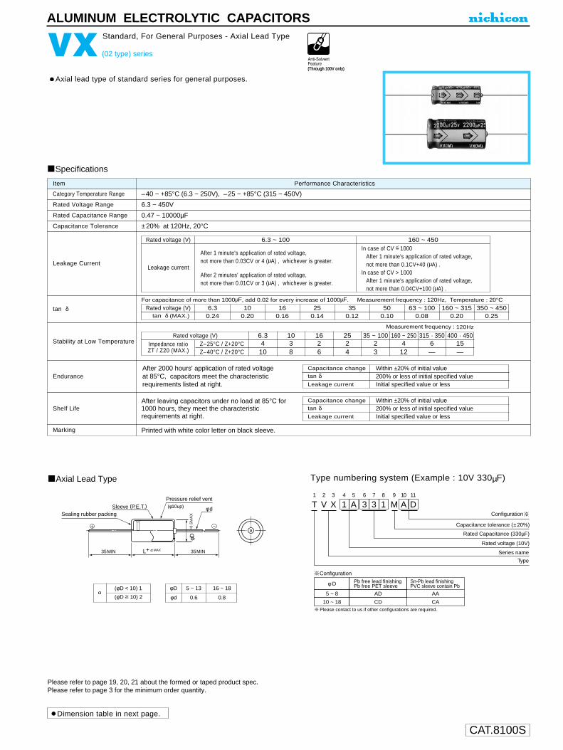
CAT.8100S
T1
V2
X3
14
A5
36
37
18
M9
A10
D11
Configuration
Capacitance tolerance (±20%)
Rated Capacitance (330µF)
Rated voltage (10V)
Series name
Type
Please contact to us if other configurations are required.
φ D
5 ~ 8
Pb free lead finishingPb free PET sleeve
Sn-Pb lead finishingPVC sleeve contain Pb
AD AA
10 ~ 18 CD CA
Configuration
φ d
Pressure relief vent
Sealing rubber packing
L+ MAX35MIN 35MIN
(φ10up)
φD +
0.5
MA
X
Sleeve (P.E.T.)
ALUMINUM ELECTROLYTIC CAPACITORS
VX (02 type) series
Standard, For General Purposes - Axial Lead Type
Axial lead type of standard series for general purposes.
Axial Lead Type Type numbering system (Example : 10V 330µF)
Category Temperature Range
Rated Capacitance Range
Capacitance Tolerance
Leakage CurrentLeakage current
tan δ
Stability at Low Temperature
Endurance
Shelf LifeAfter leaving capacitors under no load at 85°C for 1000 hours, they meet the characteristic requirements at right.
Printed with white color letter on black sleeve.Marking
Performance CharacteristicsItem
–40 ~ +85°C (6.3 ~ 250V), –25 ~ +85°C (315 ~ 450V)
0.47 ~ 10000µF
6.3 ~ 450V
±20% at 120Hz, 20°C
Rated Voltage Range
Specifications
Rated voltage (V)Impedance rat ioZT / Z20 (MAX.)
Z–25°C / Z+20°CZ–40°C / Z+20°C
6.34
10
1038
1626
2524
35 ~ 10023
160 ~ 2504
12
315 · 3506—
400 · 45015—
Measurement frequency : 120Hz
Capacitance change
Leakage current
tan δWithin ±20% of initial value
Initial specified value or less200% or less of initial specified value
After 2000 hours' application of rated voltage at 85°C, capacitors meet the characteristic requirements listed at right.
Rated voltage (V) 6.3 ~ 100 160 ~ 450
After 1 minute's application of rated voltage,not more than 0.03CV or 4 (µA) , whichever is greater.
After 2 minutes' application of rated voltage,not more than 0.01CV or 3 (µA) , whichever is greater.
In case of CV 1000After 1 minute's application of rated voltage,not more than 0.1CV+40 (µA) .
In case of CV > 1000After 1 minute's application of rated voltage,not more than 0.04CV+100 (µA) .
Rated voltage (V)tan δ (MAX.)
6.30.24
100.20
160.16
250.14
350.12
500.10
63 ~ 1000.08
160 ~ 3150.20
350 ~ 4500.25
For capacitance of more than 1000µF, add 0.02 for every increase of 1000µF. Measurement frequency : 120Hz, Temperature : 20°C
Dimension table in next page.
φD 5 ~ 13 16 ~ 18
φd 0.6 0.8α
(φD < 10) 1
(φD 10) 2
Capacitance change
Leakage current
tan δWithin ±20% of initial value
Initial specified value or less200% or less of initial specified value
Please refer to page 19, 20, 21 about the formed or taped product spec.Please refer to page 3 for the minimum order quantity.
(Through 100V only)
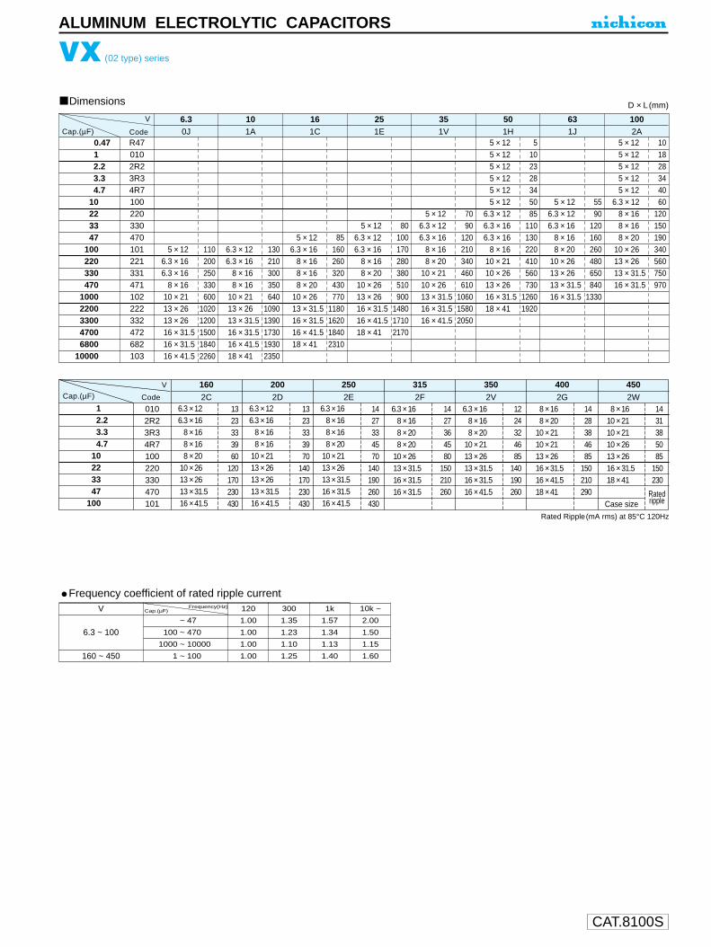
CAT.8100S
ALUMINUM ELECTROLYTIC CAPACITORS
0.4712.23.34.7
10223347
100220330470
10002200330047006800
10000
VX (02 type) series
Dimensions
R470102R23R34R7100220330470101221331471102222332472682103
5 × 126.3 × 166.3 × 16
8 × 1610 × 2113 × 2613 × 2616 × 31.516 × 31.516 × 41.5
110200250330600
10201200150018402260
6.3V
Code 0J
6.3 × 126.3 × 16
8 × 168 × 16
10 × 2113 × 2613 × 31.516 × 31.516 × 41.518 × 41
130210300350640
10901390173019302350
101A
5 × 126.3 × 16
8 × 168 × 168 × 20
10 × 2613 × 31.516 × 31.516 × 41.518 × 41
85160260320430770
1180162018402310
161C
5 × 126.3 × 126.3 × 16
8 × 168 × 20
10 × 2613 × 2616 × 31.516 × 41.518 × 41
80100170280380510900
148017102170
251E
5 × 126.3 × 126.3 × 16
8 × 168 × 20
10 × 2110 × 2613 × 31.516 × 31.516 × 41.5
7090
120210340460610
106015802050
351V
5 × 125 × 125 × 125 × 125 × 125 × 12
6.3 × 126.3 × 166.3 × 16
8 × 1610 × 2110 × 2613 × 2616 × 31.518 × 41
5102328345085
110130220410560730
12601920
501H
5 × 126.3 × 126.3 × 16
8 × 168 × 20
10 × 2613 × 2613 × 31.516 × 31.5
5590
120160260480650840
1330
631J
5 × 125 × 125 × 125 × 125 × 12
6.3 × 128 × 168 × 168 × 20
10 × 2613 × 2613 × 31.516 × 31.5
101828344060
120150190340560750970
1002A
D × L (mm)
Frequency coefficient of rated ripple currentV Frequency(Hz)
Cap.(µF)
6.3 ~ 100
160 ~ 450
0 ~ 47
100 ~ 470
1000 ~ 10000
1 ~ 100
120
1.00
1.00
1.00
1.00
300
1.35
1.23
1.10
1.25
1k
1.57
1.34
1.13
1.40
10k ~
2.00
1.50
1.15
1.60
Rated Ripple(mA rms) at 85°C 120Hz
12.23.34.7
10223347
100
0102R23R34R7100220330470101
6.3 × 126.3 × 16
8 × 168 × 168 × 20
10 × 2613 × 2613 × 31.516 × 41.5
1323333960
120170230430
2C
V 160
6.3 × 126.3 × 16
8 × 168 × 16
10 × 2113 × 2613 × 2613 × 31.516 × 41.5
1323333970
140170230430
2D
200
6.3 × 168 × 168 × 168 × 20
10 × 2113 × 2613 × 31.516 × 31.516 × 41.5
1427334570
140190260430
2E
250
6.3 × 168 × 168 × 208 × 20
10 × 2613 × 31.516 × 31.516 × 31.5
1427364580
150210260
2F
315
6.3 × 168 × 168 × 20
10 × 2113 × 2613 × 31.516 × 31.516 × 41.5
1224324685
140190260
2V
350
8 × 168 × 20
10 × 2110 × 2113 × 2616 × 31.516 × 41.518 × 41
1428384685
150210290
1431385085
150230
2G
400
8 × 1610 × 2110 × 2110 × 2613 × 2616 × 31.518 × 41
Case size
2W
450Code
Ratedripple
Cap.(µF)
Cap.(µF)

CAT.8100S
φD
P
φd
5
2.0
0.5
6.3
2.5
0.5
8
3.5
0.6
10
5.0
0.6
12.5
5.0
0.6
16
7.5
0.8
18
7.5
0.8
20 22
10.0 10.0
1.0 1.0
U1
V2
Y3
14
A5
36
37
18
M9
E10
D11
Configuration
Capacitance tolerance (±20%)
Rated Capacitance (330µF)
Rated voltage (10V)
Series name
Type
25
12.5
1.0
0.5 0.5 0.5 0.5 0.5 0.5 0.5 0.5 1.0 1.0
P±0
.5
(φ6.3up)15MIN 4MIN
Sleeve (P.E.T.)
Pressurerelief vent
φd
φD+
M
AX
L+ MAX
(L < 20) 1.5(L 20) 2.0
φ D
5
Pb free lead finishingPb free PET sleeve
DD
6.3 ED
8 · 10 PD
HD
Configuration
RD
12.5 ~ 18
20 ~ 25 Please contact to us if other configurations are required.
VY
VZ
VK
ALUMINUM ELECTROLYTIC CAPACITORS
VY series
Wide Temperature Range
One rank smaller case sizes than VZ series.
Radial Lead Type
Specifications
Type numbering system (Example : 10V 330µF)
Category Temperature Range
Rated Voltage Range
Rated Capacitance Range
Capacitance Tolerance
Leakage Current
tan δ
Stability at Low Temperature
Endurance
Shelf Life
Marking
Performance CharacteristicsItem
– 55 ~ +105˚C (6.3 ~ 100V), – 40 ~ +105˚C (160 ~ 400V), – 25 ~ +105˚C (450V)
6.3 ~ 450V
0.1 ~ 68000µF
±20% at 120Hz, 20˚C
Printed with white color letter on black sleeve.
After leaving capacitors under no load at 105˚C for 1000 hours, they meet the specifiedvalue for endurance characteristics listed above.
Rated voltage (V) 6.3 ~ 100 160 ~ 450After 1 minute's application of rated voltage, leakage currentis not more than 0.03CV or 4 (µA), whichever is greater.
After 2 minutes' application of rated voltage, leakage currentis not more than 0.01CV or 3 (µA), whichever is greater.
After 1 minute's application of rated voltage,CV <= 1000 : I =0.1CV+40 (µA) or less
After 1 minute's application of rated voltage,CV > 1000 : I =0.04CV+100 (µA) or less
Measurement frequency : 120Hz
Z–25˚C / Z+20˚C
Z–40˚C / Z+20˚C
Rated voltage (V)
Impedance ratioZT / Z20 (MAX.)
6.3510
1048
1636
2524
160 ~ 20034
35 ~ 5023
63 ~ 10023
250 ~ 35048
400610
45015—
After 1000 hours' application of rated voltage at 105˚C, capacitors meet the characteristic requirements listed at right.
Rated voltage (V)
tan δ (MAX.)6.30.28
100.24
160.20
250.16
350.14
500.12
630.10
1000.08
160 ~ 2500.20
350 ~ 4500.25
For capacitance of more than 1000µF, add 0.02 for every increase of 1000µF. Measurement frequency : 120Hz, Temperature : 20˚C
Leakage current
tan δCapacitance change
Initial specified value or less200% or less of initial specified valueWithin ±20% of initial value
The laminated case is also available upon request.Please refer to page 19, 20, 21 about the formed or taped product spec.Please refer to page 3 for the minimum order quantity.
Smaller
HighTemperature
Dimension table in next page.

CAT.8100S
0.1
0.22
0.33
0.47
1
2.2
3.3
4.7
10
22
33
47
68
100
220
330
470
1000
2200
3300
4700
6800
10000
15000
22000
33000
47000
68000
0R1
R22
R33
R47
010
2R2
3R3
4R7
100
220
330
470
680
101
221
331
471
102
222
332
472
682
103
153
223
333
473
683
0J 1A 1C 1E 1V 1H 1J
6.3 10 16 25 35 50 63
8 × 11.5
10 × 16
10 × 20
12.5 × 20
12.5 × 25
16 × 25
16 × 31.5
18 × 35.5
20 × 40
22 × 50
25 × 50
390
635
840
1090
1350
1650
1820
2280
2500
2780
3070
D × L (mm)
5 × 11
6.3 × 11
6.3 × 11
10 × 12.5
10 × 16
12.5 × 20
12.5 × 25
16 × 25
16 × 31.5
16 × 35.5
18 × 40
22 × 50
25 × 50
155
210
250
460
705
1000
1260
1570
1820
2050
2420
3210
3570
6.3 × 11
6.3 × 11
8 × 11.5
10 × 12.5
10 × 20
12.5 × 25
16 × 25
16 × 25
16 × 35.5
18 × 40
22 × 40
25 × 50
190
225
315
500
710
1170
1500
1600
1930
2210
2710
3450
5 × 11
6.3 × 11
8 × 11.5
10 × 12.5
10 × 16
12.5 × 25
16 × 25
16 × 25
16 × 35.5
18 × 40
22 × 50
25 × 50
125
200
275
380
610
1090
1400
1570
1850
2000
2750
3250
5 × 11
6.3 × 11
6.3 × 11
8 × 11.5
10 × 12.5
10 × 16
12.5 × 20
16 × 25
16 × 31.5
16 × 35.5
18 × 40
22 × 50
25 × 50
93
110
150
250
350
460
810
1260
1500
1780
2000
2650
3100
5 × 11
5 × 11
5 × 11
5 × 11
5 × 11
5 × 11
5 × 11
5 × 11
5 × 11
5 × 11
5 × 11
6.3 × 11
6.3 × 11
8 × 11.5
10 × 12.5
10 × 16
10 × 20
12.5 × 25
16 × 31.5
18 × 35.5
20 × 40
22 × 50
25 × 50
1.3
2.9
4.3
7
13
20
25
30
46
68
90
115
150
190
300
410
540
950
1410
1770
2100
2500
2850
5 × 11
6.3 × 11
6.3 × 11
8 × 11.5
8 × 11.5
10 × 16
10 × 20
12.5 × 20
16 × 25
18 × 35.5
20 × 40
22 × 50
25 × 50
Case size
71
100
120
155
200
335
510
640
930
1650
1950
2450
2800
Rated
ripple
Cap.(µF)
00 ~ 68100 ~ 470
1000 ~ 680000.1 ~ 220
330 ~ 1000
6.3 ~ 100
V
160 ~ 450
50Hz 120Hz 300Hz 1 kHz 10 kHz ~0.75 1.00 1.35 1.57 2.000.80 1.00 1.23 1.34 1.500.85 1.00 1.10 1.13 1.150.80 1.00 1.25 1.40 1.600.90 1.00 1.10 1.13 1.15
Frequency
0.1
0.22
0.33
0.47
1
2.2
3.3
4.7
10
22
33
47
68
100
220
330
470
1000
2200
3300
0R1
R22
R33
R47
010
2R2
3R3
4R7
100
220
330
470
680
101
221
331
471
102
222
332
2A 2C 2D 2E 2V 2G 2W
100 160 200 250 350 400 450
5 × 11
5 × 11
5 × 11
5 × 11
5 × 11
5 × 11
5 × 11
5 × 11
5 × 11
6.3 × 11
8 × 11.5
8 × 11.5
10 × 12.5
10 × 16
12.5 × 20
12.5 × 25
16 × 25
18 × 35.5
22 × 50
25 × 50
1.5
3.4
5.0
7.1
15
21
29
32
50
93
130
140
190
240
390
540
715
960
1750
2070
8 × 11.5
10 × 12.5
10 × 16
10 × 20
12.5 × 20
12.5 × 25
16 × 31.5
18 × 35.5
18 × 40
25 × 50
41
92
125
150
250
310
410
570
855
1350
6.3 × 11
6.3 × 11
6.3 × 11
6.3 × 11
6.3 × 11
6.3 × 11
6.3 × 11
6.3 × 11
8 × 11.5
10 × 16
10 × 20
12.5 × 20
12.5 × 25
16 × 25
16 × 35.5
18 × 40
22 × 40
1.5
3.3
5
11
16
25
30
35
57
105
140
195
250
320
500
675
925
6.3 × 11
6.3 × 11
10 × 12.5
10 × 20
10 × 20
12.5 × 20
16 × 25
16 × 25
18 × 35.5
20 × 40
22 × 50
28
35
71
105
140
190
270
310
485
710
1000
6.3 × 11
8 × 11.5
8 × 11.5
10 × 12.5
12.5 × 20
12.5 × 25
16 × 25
16 × 25
18 × 35.5
22 × 50
25 × 50
21
30
39
64
105
170
210
285
370
540
710
6.3 × 11
6.3 × 11
8 × 11.5
8 × 11.5
10 × 12.5
10 × 16
12.5 × 25
16 × 25
16 × 25
16 × 31.5
18 × 35.5
22 × 50
8.5
14
27
34
42
64
140
170
200
240
310
460
8 × 11.5
10 × 12.5
10 × 12.5
10 × 20
12.5 × 25
16 × 25
16 × 31.5
18 × 35.5
18 × 40
25 × 50
Case size
20
28
32
27
100
125
155
185
200
250
Rated
ripple
Rated Ripple (mA rms) at 105˚C 120Hz
VY series
ALUMINUM ELECTROLYTIC CAPACITORS
Dimensions
Frequency coefficient of rated ripple current
Cap.(µF) Code
V
Cap.(µF) Code
V
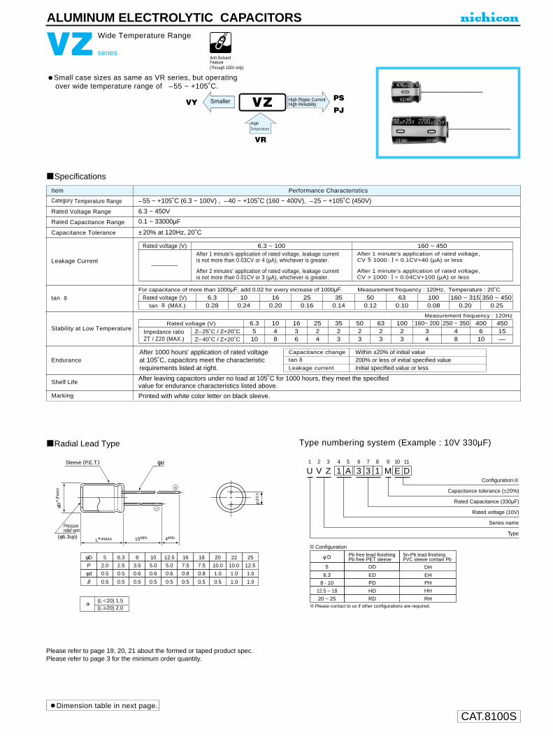
CAT.8100S
ALUMINUM ELECTROLYTIC CAPACITORS
VZ series
Wide Temperature Range
Small case sizes as same as VR series, but operatingover wide temperature range of –55 ~ +105˚C.
Radial Lead Type
Specifications
Type numbering system (Example : 10V 330µF)
Category Temperature Range
Rated Voltage Range
Rated Capacitance Range
Capacitance Tolerance
Leakage Current
tan δ
Stability at Low Temperature
Endurance
Shelf Life
Marking
Performance CharacteristicsItem
–55 ~ +105˚C (6.3 ~ 100V) , –40 ~ +105˚C (160 ~ 400V), –25 ~ +105˚C (450V)
6.3 ~ 450V
0.1 ~ 33000µF
±20% at 120Hz, 20˚C
Printed with white color letter on black sleeve.
After leaving capacitors under no load at 105˚C for 1000 hours, they meet the specifiedvalue for endurance characteristics listed above.
Rated voltage (V) 6.3 ~ 100 160 ~ 450After 1 minute's application of rated voltage, leakage currentis not more than 0.03CV or 4 (µA), whichever is greater.
After 2 minutes' application of rated voltage, leakage currentis not more than 0.01CV or 3 (µA), whichever is greater.
After 1 minute's application of rated voltage,CV <= 1000 : I = 0.1CV+40 (µA) or less
After 1 minute's application of rated voltage,CV > 1000 : I = 0.04CV+100 (µA) or less
Measurement frequency : 120Hz
Z–25˚C / Z+20˚C
Z–40˚C / Z+20˚C
Rated voltage (V)
Impedance ratioZT / Z20 (MAX.)
6.3510
1048
1636
2524
3523
5023
6323
10023
160~ 20034
250 ~ 35048
400610
45015—
After 1000 hours' application of rated voltage at 105˚C, capacitors meet the characteristic requirements listed at right.
VZ
VR
PS
PJHigh Rippie CurrentHigh Reliability
U1
V2
Z3
14
A5
36
37
18
M9
E10
D11
Configuration
Capacitance tolerance (±20%)
Rated Capacitance (330µF)
Rated voltage (10V)
Series name
Type
DH
EH
PH
HH
RH
Pressurerelief vent
15MIN 4MIN
φd
φD+
M
AX
P±0
.5
(φ6.3up)L+ MAX
φ D
5
Pb free lead finishingPb free PET sleeve
Sn-Pb lead finishingPVC sleeve contain Pb
DD
6.3 ED
8 · 10 PD
12.5 ~ 18 HD
20 ~ 25 RD
Configuration
Sleeve (P.E.T.)
Please contact to us if other configurations are required.
φD
P
φd
5
2.0
0.5
6.3
2.5
0.5
8
3.5
0.6
10
5.0
0.6
12.5
5.0
0.6
16
7.5
0.8
18
7.5
0.8
20 22
10.0 10.0
1.0 1.0
25
12.5
1.0
0.5 0.5 0.5 0.5 0.5 0.5 0.5 0.5 1.0 1.0
(L 20) 1.5(L 20) 2.0
Rated voltage (V)
tan δ (MAX.)6.30.28
100.24
160.20
250.16
350.14
500.12
630.10
1000.08
160 ~ 3150.20
350 ~ 4500.25
For capacitance of more than 1000µF, add 0.02 for every increase of 1000µF. Measurement frequency : 120Hz, Temperature : 20˚C
HighTemperature
Leakage current
tan δCapacitance change
Initial specified value or less200% or less of initial specified valueWithin ±20% of initial value
Please refer to page 19, 20, 21 about the formed or taped product spec.Please refer to page 3 for the minimum order quantity.
SmallerVY
(Through 100V only)
Dimension table in next page.

CAT.8100S
VZ series
ALUMINUM ELECTROLYTIC CAPACITORS
Dimensions
0.1
0.22
0.33
0.47
1
2.2
3.3
4.7
10
22
33
47
100
220
330
470
1000
2200
3300
4700
6800
10000
15000
22000
33000
0R1
R22
R33
R47
010
2R2
3R3
4R7
100
220
330
470
101
221
331
471
102
222
332
472
682
103
153
223
333
V
0J
6.3
1H
50
5 × 11.5
5 × 11.5
5 × 11.5
5 × 11.5
5 × 11.5
6.3 × 11.5
6.3 × 11.5
8 × 11.5
10 × 20.5
10 × 20.5
12.5 × 20.5
12.5 × 25.5
16 × 25.5
16 × 35.5
18 × 40.5
22 × 50.5
45
55
65
95
145
195
230
390
710
840
1090
1350
1650
2010
2350
2800
1.3
2.9
4.3
7
13
20
25
30
46
68
90
115
190
300
410
530
950
1470
1770
2100
2500
2850
D × L (mm)
1V
35
5 × 11.5
5 × 11.5
5 × 11.5
5 × 11.5
5 × 11.5
6.3 × 11.5
10 × 12.5
10 × 12.5
10 × 16.5
12.5 × 20.5
16 × 25.5
16 × 35.5
18 × 35.5
20 × 40.5
22 × 50.5
25 × 50.5
28
41
61
75
93
150
275
350
460
810
1260
1610
1910
2150
2650
3100
1E
25
5 × 11.5
5 × 11.5
5 × 11.5
5 × 11.5
5 × 11.5
6.3 × 11.5
8 × 11.5
10 × 12.5
10 × 12.5
10 × 20.5
12.5 × 25.5
16 × 25.5
16 × 31.5
18 × 35.5
20 × 40.5
22 × 50.5
25 × 50.5
25
36
58
68
83
140
240
315
380
680
1090
1400
1710
2040
2150
2750
3250
1C
16
5 × 11.5
5 × 11.5
5 × 11.5
5 × 11.5
5 × 11.5
6.3 × 11.5
8 × 11.5
8 × 11.5
10 × 16.5
12.5 × 20.5
12.5 × 25.5
16 × 25.5
16 × 35.5
18 × 35.5
20 × 40.5
22 × 50.5
25 × 50.5
35
54
65
79
115
190
265
315
560
920
1170
1480
1780
2060
2430
3000
3450
1A
10
5 × 11.5
5 × 11.5
5 × 11.5
5 × 11.5
6.3 × 11.5
6.3 × 11.5
6.3 × 11.5
10 × 12.5
10 × 20.5
12.5 × 20.5
12.5 × 25.5
16 × 25.5
16 × 35.5
18 × 35.5
20 × 40.5
22 × 50.5
45
58
68
105
175
210
250
460
760
1000
1260
1570
1890
2180
2650
3250
5 × 11.5
5 × 11.5
5 × 11.5
5 × 11.5
5 × 11.5
5 × 11.5
5 × 11.5
5 × 11.5
5 × 11.5
5 × 11.5
5 × 11.5
6.3 × 11.5
8 × 11.5
10 × 12.5
10 × 16.5
12.5 × 20.5
12.5 × 25.5
16 × 35.5
18 × 35.5
20 × 40.5
22 × 50.5
25 × 50.5
Case size
0.1
0.22
0.33
0.47
1
2.2
3.3
4.7
10
22
33
47
100
220
330
470
1000
2200
3300
4700
6800
0R1
R22
R33
R47
010
2R2
3R3
4R7
100
220
330
470
101
221
331
471
102
222
332
472
682
2W
450
13
23
31
40
65
115
165
185
270
Rated Ripple (mA rms) at 105˚C 120Hz
8 × 11.5
10 × 12.5
10 × 16.5
10 × 20.5
12.5 × 20.5
16 × 25.5
16 × 35.5
18 × 40.5
22 × 40.5
Case size
2G
400
17
30
38
50
90
165
215
270
450
660
2V
350
15
26
38
45
80
115
195
270
420
620
6.3 × 11.5
8 × 11.5
10 × 12.5
10 × 12.5
10 × 20.5
12.5 × 25.5
16 × 25.5
16 × 35.5
18 × 40.5
22 × 50.5
2F
315
15
26
38
45
80
115
195
230
395
620
760
6.3 × 11.5
8 × 11.5
10 × 12.5
10 × 12.5
10 × 20.5
12.5 × 20.5
16 × 25.5
16 × 25.5
18 × 35.5
22 × 50.5
25 × 50.5
2E
250
10
15
23
32
39
74
130
160
210
365
600
730
870
6.3 × 11.5
6.3 × 11.5
6.3 × 11.5
8 × 11.5
8 × 11.5
10 × 16.5
12.5 × 20.5
12.5 × 20.5
12.5 × 25.5
16 × 31.5
20 × 40.5
22 × 50.5
25 × 50.5
2D
200
11
16
25
30
39
65
120
160
195
375
575
705
840
0
6.3 × 11.5
6.3 × 11.5
6.3 × 11.5
6.3 × 11.5
8 × 11.5
10 × 12.5
10 × 20.5
12.5 × 20.5
12.5 × 20.5
16 × 31.5
18 × 35.5
20 × 40.5
22 × 50.5
2C
160
11
16
25
30
34
41
100
145
195
215
570
750
900
1310
6.3 × 11.5
6.3 × 11.5
6.3 × 11.5
6.3 × 11.5
6.3 × 11.5
8 × 11.5
10 × 16.5
10 × 20.5
12.5 × 20.5
12.5 × 25.5
16 × 35.5
18 × 40.5
22 × 40.5
25 × 50.5
2A
100
1.5
3.4
5.0
7.1
15
21
29
32
54
93
130
165
265
440
540
715
985
1750
2070
5 × 11.5
5 × 11.5
5 × 11.5
5 × 11.5
5 × 11.5
5 × 11.5
5 × 11.5
5 × 11.5
6.3 × 11.5
6.3 × 11.5
8 × 11.5
10 × 12.5
10 × 20.5
12.5 × 25.5
12.5 × 25.5
16 × 25.5
18 × 40.5
22 × 50.5
25 × 50.5
1J
63
46
71
100
120
215
335
510
640
930
1650
1950
2450
2800
5 × 11.5
5 × 11.5
6.3 × 11.5
6.3 × 11.5
10 × 12.5
10 × 16.5
10 × 20.5
12.5 × 20.5
16 × 25.5
18 × 35.5
20 × 40.5
22 × 50.5
25 × 50.5
Frequency coefficient of rated ripple current
00~ 47100 ~ 470
1000 ~ 330000.47 ~ 220330 ~ 1000
6.3 ~ 100
V
160 ~ 450
50Hz 120Hz 300Hz 1 kHz 10 kHz ~0.75 1.00 1.35 1.57 2.000.80 1.00 1.23 1.34 1.500.85 1.00 1.10 1.13 1.150.80 1.00 1.25 1.40 1.600.90 1.00 1.10 1.13 1.15
0
8 × 11.5
10 × 12.5
10 × 12.5
10 × 16.5
12.5 × 20.5
16 × 25.5
16 × 31.5
16 × 35.5
20 × 40.5
25 × 50.5
CodeCap.(µF)
CodeCap.(µF)
V
FrequencyCap.(µF)
Ratedripple
Ratedripple
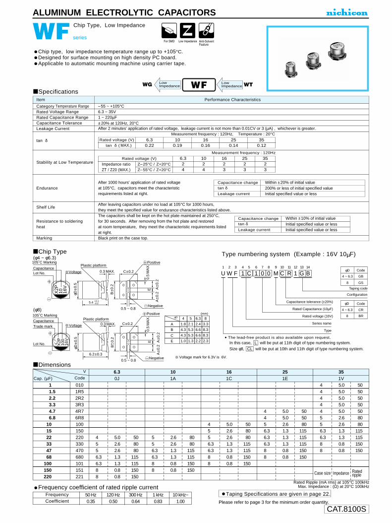
CAT.8100S
ALUMINUM ELECTROLYTIC CAPACITORS
Voltage mark for 6.3V is 6V.
105˚C Marking
VoltageCapacitanceLot No.
X2P
10 16V
Plastic platform
0.3 MAX.
5.4 +0.1-0.2
φD±0
.5
B±0
.2
C±0.2
0.5
MA
X.
A±0
.2 A
±0.2
E
0.5 ~ 0.8
Positive
Negative
105˚C Marking
VoltageCapacitance Plastic platform
0.3 MAX.
6.2±0.3
φD±0
.5
B+ –
0.2
C±0.2
0.5
MA
X.
A±0
.2 A
±0.2
E
0.5 ~ 0.8
Positive
Negative
φD 4
A
B
C
E
5 6.3 8
1.8 2.1 2.4 3.3
4.3 5.3 6.6 8.3
4.3 5.3 6.6 8.3
1.0 1.3 2.2 2.3
(mm)
Trade mark
Lot No. X2P
100
16V
U1
W2
F3
14
C5
16
07
08
M9
C10
R11
112
G13
B14
Configuration
Taping code
Capacitance tolerance (±20%)
Rated Capacitance (10µF)
Rated voltage (16V)
Series name
Type
φD
4 ~ 6.3
8
Code
GB
GS
φD
4 ~ 6.3
8
Code
CR
BR
WF series
Chip Type, Low Impedance
Chip type, low impedance temperature range up to +105°C.Designed for surface mounting on high density PC board.Applicable to automatic mounting machine using carrier tape.
Chip Type(φ4 ~ φ6.3)
(φ8)
Specifications
Category Temperature RangeRated Voltage RangeRated Capacitance RangeCapacitance ToleranceLeakage Current
tan δ
Stability at Low Temperature
Endurance
Shelf Life
Resistance to solderingheat
Marking
Performance CharacteristicsItem
–55 ~ +105°C6.3 ~ 35V1 ~ 220µF±20% at 120Hz, 20°CAfter 2 minutes' application of rated voltage, leakage current is not more than 0.01CV or 3 (µA) , whichever is greater.
Black print on the case top.
Measurement frequency : 120Hz, Temperature : 20°C
Measurement frequency : 120Hz
After 1000 hours' application of rated voltage at 105°C, capacitors meet the characteristic requirements listed at right.
After leaving capacitors under no load at 105°C for 1000 hours, they meet the specified value for endurance characteristics listed above.
Rated voltage (V)
tan δ ( MAX.) 6.30.22
100.19
160.16
250.14
350.12
Z–25°C / Z+20°C
Z–55°C / Z+20°C
Rated voltage (V)
Impedance ratioZT / Z20 (MAX.)
6.324
1024
1623
2523
3523
Dimensions
Rated Ripple (mA rms) at 105°C 100kHzMax. Impedance : (Ω) at 20°C 100kHz
WF
Type numbering system (Example : 16V 10µF)
The capacitors shall be kept on the hot plate maintained at 250°C,for 30 seconds. After removing from the hot plate and restoredat room temperature, they meet the characteristic requirements listedat right.
WT
11.52.23.34.76.8
101522334768
100150220
0101R52R23R34R76R8100150220330470680101151221
4556.36.388
0J6.3
1A10
1C16
1E25
1V35
5.02.62.61.31.30.80.8
508080
115115150150
556.36.388
2.62.61.31.30.80.8
8080
115115150150
4556.36.388
5.02.62.61.31.30.80.8
508080
115115150150
4456.36.36.388
5.05.02.61.31.31.30.80.8
505080
115115115150150
44444556.36.388
5.05.05.05.05.02.62.61.31.30.80.8
50505050508080
115115150150
V
CodeCap. (µF)
Case size Impedance Ratedripple
LowImpedance
Capacitance change
Leakage current
tan δWithin ±20% of initial value
Initial specified value or less200% or less of initial specified value
Capacitance change
Leakage current
tan δWithin ±10% of initial value
Initial specified value or lessInitial specified value or less
WG LowImpedance
Please refer to page 3 for the minimum order quantity.
Taping Specifications are given in page 22.Frequency coefficient of rated ripple current
CoefficientFrequency 50 Hz 120 Hz 300 Hz 1 kHz 10 kHz~
0.35 0.50 0.64 0.83 1.00
• The lead-free product is also available upon request.In this case, will be put at 11th digit of type numbering system.
Size φ8, will be put at 10th and 11th digit of type numbering system.CLL

CAT.8100S
ALUMINUM ELECTROLYTIC CAPACITORS
WG series
Chip Type, Low Impedance
Chip type, operating over wide temperature range of to –55 ~ +105°C.Designed for surface mounting on high density PC board.Applicable to automatic mounting machine using carrier tape.
Chip Type Type numbering system (Example : 10V 100µF)
Specifications
Category Temperature Range
Rated Voltage Range
Rated Capacitance Range
Capacitance Tolerance
Leakage Current
tan δ
Stability at Low Temperature
Endurance
Shelf Life
Marking
Performance CharacteristicsItem
–55 ~ +105°C
6.3 ~ 50V
1 ~ 1500µF
±20% at 120Hz, 20°C
After 2 minutes' application of rated voltage, leakage current is not more than 0.01CV or 3 (µA) , whichever is greater.
Black print on the case top.
Measurement frequency : 120Hz, Temperature : 20°C
Measurement frequency : 120Hz
After 1000 hours' application of rated voltageat 105°C, capacitors meet the characteristic requirements listed at right.
After leaving capacitors under no load at 105°C for 1000 hours,they meet the specified value for endurance characteristics listed above.
Resistance to solderingheat
The capacitors shall be kept on the hot plate maintained at 250°Cfor 30 seconds. After removing from the hot plate and restoredat room temperature, they meet the characteristic requirementslisted at right.
Rated voltage (V) tan δ (MAX.)
6.30.26
100.19
160.16
250.14
350.12
500.12
Z–25°C / Z+20°C
Z–40°C / Z+20°C
Rated voltage (V)
Impedance ratioZT / Z20 (MAX.)
6.324
1024
1623
2523
3523
5023
WG
Capacitance change
Leakage current
tan δWithin ±20% of initial value200% or less of initial specified valueInitial specified value or less
Capacitance change
Leakage current
tan δWithin ±10% of initial valueInitial specified value or lessInitial specified value or less
Dimension table in next page.
ABCELH
4 × 5.4
1.84.34.31.05.4
0.5 ~ 0.8
5 × 5.4
2.15.35.31.35.4
0.5 ~ 0.8
6.3 × 5.4
2.46.66.62.25.4
0.5 ~ 0.8
8 × 6.2
3.38.38.32.36.2
0.5 ~ 0.8
8 × 10
2.98.38.33.110
0.8 ~ 1.1
10 × 10
3.210.310.34.510
0.8 ~ 1.1
φD × L
(mm)
VoltageCapacitance
105°C Marking
105°C Marking
105°C Marking
(φ4 ~ φ6.3)
(φ8 × 6.2L)
(φ8 × 10L, φ10 × 10L)
X2P
100
6V
Plastic platform0.3 MAX.
L
φD±0
.5
B±0
.2
C±0.2
0.5
MA
X.
A±0
.2
A±0
.2
E
H
Positive
Negative
Trade mark
Lot No.
Voltage mark for 6.3V is 6V .
Voltage
Capacitance
X2P
100
10V
Plastic platform0.3 MAX.
L±0.3
φD±0
.5
B±0
.2
C±0.2
0.5
MA
X.
A±0
.2
A±0
.2
E
H
Positive
NegativeLot No.
Trade markVoltage
Capacitance
X2P
220
25V
Plastic platform
Pressure relief vent
0.3 MAX.
L±0.5
φD±0
.5
B±0
.2
C±0.2
0.5
MA
X.
A±0
.2
A±0
.2
E
H
Positive
NegativeLot No.
+0.1-0.2
U1
W2
G3
14
A5
16
07
18
M9
C10
R G S11
112 13 14
Configuration
Taping code
Capacitance tolerance (±20%)
Rated Capacitance (100µF)
Rated voltage (10V)
Series name
Type
φD4 ~ 6.38 • 10
codeGBGS
φD4 ~ 6.38 (6.2L)
codeCRCR
8 (10L) • 10 NR
WFLowImpedanceUD Low
Impedance
• The lead-free product is also available upon request.In this case, will be put at 11th digit of type numbering system.
Size φ8 x 6.2, will be put at 10th and 11th digit of type numbering system.CL
L

CAT.8100S
3.0
1.8
1.0
0.4
0.4
0.15
0.15
0.15
0.15
5 × 5.4
8 × 6.2
8 × 6.2
8 × 10
10 × 10
10 × 10
ALUMINUM ELECTROLYTIC CAPACITORS
WG series
Dimensions
Rated Ripple (mA rms) at 105°C 100kHzMax. Impedance : (Ω) at 20°C 100kHz
10
22
33
47
68
100
150
220
330
470
680
1000
1500
100
220
330
470
680
101
151
221
331
471
681
102
152
4 × 5.4
5 × 5.4
6.3 × 5.4
6.3 × 5.4
8 × 6.2
8 × 10
10 × 10
10 × 10
3.0
1.8
1.0
1.0
0.4
0.3
0.15
0.15
60
95
140
140
230
450
670
670
0J
6.3
1A
10
1C
16
1.8
0.4
0.4
0.3
0.15
0.15
95
230
230
450
670
670
4 × 5.4
5 × 5.4
6.3 × 5.4
8 × 6.2
8 × 6.2
10 × 10
10 × 10
10 × 10
10 × 10
60
95
140
230
230
670
670
670
670
5.0
5.0
5.0
3.0
2.0
0.7
0.6
0.3
0.3
0.3
4 × 5.4
4 × 5.4
4 × 5.4
4 × 5.4
5 × 5.4
5 × 5.4
6.3 × 5.4
8 × 6.2
8 × 6.2
10 × 10
10 × 10
10 × 10
4 × 5.4
6.3 × 5.4
6.3 × 5.4
8 × 6.2
8 × 10
8 × 10
10 × 10
10 × 10
10 × 10
3.0
1.0
1.0
0.4
0.3
0.3
0.15
0.15
0.15
60
140
140
230
450
450
670
670
670
3.0
3.0
3.0
3.0
1.8
1.8
1.0
0.4
0.4
0.15
0.15
0.15
60
60
60
60
95
95
140
230
230
670
670
670
4 × 5.4
4 × 5.4
4 × 5.4
5 × 5.4
6.3 × 5.4
8 × 6.2
8 × 10
10 × 10
10 × 10
10 × 10
30
30
30
50
70
120
300
500
500
500
V
CodeCap.(µF)
1
2.2
3.3
4.7
6.8
10
22
33
47
68
100
220
330
470
010
2R2
3R3
4R7
6R8
100
220
330
470
680
101
221
331
471
1H
50
1E
25
1V
35V
CodeCap.(µF)
ImpedanceCase size Ratedripple
Please refer to page 3 for the minimum order quantity.
Taping Specifications are given in page 22.
Frequency coefficient of rated ripple current
CoefficientFrequency 50 Hz 120 Hz 300 Hz 1 kHz 10 kHz~
0.35 0.50 0.64 0.83 1.00

CAT.8100S
U1
W2
P3
14
C5
16
07
08
M9
C10
R11
112
G13
B14
Configuration
Taping code
Capacitance tolerance (±20%)
Rated Capacitance (10µF)
Rated voltage (16V)
Series name
Type
Voltage mark for 6.3V is 6V .
Voltage
Capacitance
Lot No.
X2
10 16V
Plastic platform0.3 MAX.
5.4 +0.1–0.2
φD±0
.5
B±0
.2
C±0.2
0.5
MA
X.
A±0
.2
A±0
.2
E
0.5 ~ 0.8φD
A
B
C
E
1.8
4.3
4.3
1.0
2.1
5.3
5.3
1.3
2.4
6.6
6.6
2.2
4 5(mm)
6.3
3.3
8.3
8.3
2.3
8
WP series
5.5mmL Chip Type, Bi-Polarized
Designed for surface mounting on high density PC board.Applicable to automatic mounting machine using carrier tape.
Chip Type
Dimensions
Type numbering system (Example : 16V 10µF)
Specifications
Category Temperature Range
Rated Voltage Range
Rated Capacitance Range
Capacitance Tolerance
Leakage Current
tan δ
Stability at Low Temperature
Endurance
Shelf Life
Marking
Performance CharacteristicsItem
–40 ~ +85°C
6.3 ~ 50V
0.1 ~ 100µF
±20% at 120Hz, 20°C
After 2 minutes' application of rated voltage, leakage current is not more than 0.05CV or 10 (µA) ,whichever is greater.
Black print on the case top.
Measurement frequency : 120Hz, Temperature : 20°C
Measurement frequency : 120Hz
After 1000 hours' application of rated voltageat 85°C with the polarity inverted every 250hours, capacitors meet the characteristicrequirements listed at right.
After leaving capacitors under no load at 85°C for 1000 hours, they meet the specified value for endurance characteristics listed above.
Resistance to solderingheat
The capacitors shall be kept on the hot plate maintained at 250°Cfor 30 seconds. After removing from the hot plate and restoredat room temperature, they meet the characteristic requirementslisted at right.
WP Bi-polarizedLow Profile WXZP
Rated voltage (V) tan δ (MAX.)
6.30.24
100.20
160.17
250.17
350.15
500.15
Z–25°C / Z+20°C
Z–40°C / Z+20°C
Rated voltage (V)
Impedance ratioZT / Z20 (MAX.)
6.348
1036
1624
2524
3523
5023
Rated Ripple (mA rms) at 85°C 120Hz
0.10.220.330.4712.23.34.7
10223347
100
0R1R22R33R470102R23R34R7100220330470101
56.36.38
28374582
46.36.38
17334161
456.36.38
1223374975
556.388
1216275061
4556.38
8.416182954
44444556.38
Case size
1.02.02.84.08.4
13172036
Allowableripple
0JCap. (µF)
V 6.31A
101C
161E
251V
351H
50Code
Capacitance change
Leakage current
tan δWithin ±20% of initial value200% or less of initial specified valueInitial specified value or less
Capacitance change
Leakage current
tan δWithin ±10% of initial valueInitial specified value or lessInitial specified value or less
Ratedripple
ALUMINUM ELECTROLYTIC CAPACITORS
Please refer to page 3 for the minimum order quantity.
Taping Specifications are given in page 22.Frequency coefficient of rated ripple current
CoefficientFrequency 50 Hz 120 Hz 300 Hz 1 kHz 10 kHz~
0.70 1.00 1.17 1.36 1.50
• The lead-free product is also available upon request.In this case, will be put at 11th digit of type numbering system.L

CAT.8100S
ALUMINUM ELECTROLYTIC CAPACITORS
1Voltage
Capacitance
105°C Marking
105°C Marking
(φ3 ~ φ8 × 5.4L)
(φ8 × 10L, φ10 × 10L)
A2P
10 16V
Plastic platform0.3 MAX.
L
(L±0.3)
+0.1–0.2
φD±0
.5
B±0
.2
C±0.2
0.5
MA
X.
A±0
.2
A±0
.2
E
H
H
Positive
Negative
1Voltage
Capacitance
Trade mark
Lot No.
A2P
100
35V
Plastic platform0.3 MAX.
L±0.5
Pressure relief vent
1. Voltage mark for 6.3V is 6V . In case of marking for φ3 units, “V” for ratedvoltage is omitted.
2. In case of marking for φ3 units. Lot No is expressed by a digit (month code).
3 Apply to φ6.3 × 5.8, φ6.3 × 7.7
φD±0
.5
B±0
.2
C±0.2
0.5
MA
X.
A±0
.2
A±0
.2
E
Positive
NegativeLot No.
2
3
U1
W2
T3
14
C5
16
07
08
M9
C10
R11
112
G13
B14
Configuration
Package code
Case dia. code
Capacitance tolerance (±20%)
Rated Capacitance (10µF)
Rated voltage (16V)
Series name
Type
φD
3
4 ~ 10
code
2
1
φD
3 ~ 8 (5.4L)
6.3 ~ 10 (L 5.8)
code
GB
GS
φD
3 ~ 8 (L 7.7)
8 ~ 10 (L = 10)
code
CR
NR
A
B
C
E
L
H
3 × 5.4
1.5
3.3
3.3
0.8
5.4
0.5 ~ 0.8
4 × 5.4
1.8
4.3
4.3
1.0
5.4
0.5 ~ 0.8
5 × 5.4
2.1
5.3
5.3
1.3
5.4
0.5 ~ 0.8
6.3 × 5.4
2.4
6.6
6.6
2.2
5.4
0.5 ~ 0.8
6.3 × 5.8
2.4
6.6
6.6
2.2
5.8
0.5 ~ 0.8
6.3 × 7.7
2.4
6.6
6.6
2.2
7.7
0.5 ~ 0.8
8 × 5.4
3.3
8.3
8.3
2.3
5.4
0.5 ~ 0.8
8 × 10
2.9
8.3
8.3
3.1
10
0.8 ~ 1.1
10 × 10
3.2
10.3
10.3
4.5
10
0.8 ~ 1.1
WT series
Chip Type, Wide Temperature Range
Chip type operating over wide temperature range of to –55 ~ +105°C.Designed for surface mounting on high density PC board.Applicable to automatic mounting machine using carrier tape.
Chip Type Type numbering system (Example : 16V 10µF)
Specifications
Category Temperature Range
Rated Voltage Range
Rated Capacitance Range
Capacitance Tolerance
Leakage Current
tan δ
Stability at Low Temperature
Endurance
Shelf Life
Marking
Performance CharacteristicsItem
–55 ~ +105°C
4 ~ 50V
0.1 ~ 1500µF
±20% at 120Hz, 20°C
After 2 minutes' application of rated voltage, leakage current is not more than 0.01CV or 3 (µA) , whichever is greater.
Black print on the case top.
Measurement frequency : 120Hz, Temperature : 20°C
Measurement frequency : 120Hz
After 1000 hours' application of rated voltageat 105°C, capacitors meet the characteristic requirements listed at right.
After leaving capacitors under no load at 105°C for 1000 hours,they meet the specified value for endurance characteristics listed above.
Resistance to solderingheat
The capacitors shall be kept on the hot plate maintained at 250°Cfor 30 seconds. After removing from the hot plate and restoredat room temperature, they meet the characteristic requirementslisted at right.
Rated voltage (V) tan δ (MAX.)
40.40
6.30.30
100.24
160.20
250.16
350.14
500.14
Z–25°C / Z+20°C
Z–40°C / Z+20°C
Rated voltage (V)
Impedance ratioZT / Z20 (MAX.)
4715
6.348
1038
1624
2524
3523
5023
WT
WX
Capacitancechange
Leakage current
tan δ
Within ±25% of initial value for capacitors of φ3mm unit, and 16V or less.Within ±20% of initial value for capacitors of 25V or more.200% or less of initial specified valueInitial specified value or less
Capacitance change
Leakage current
tan δWithin ±10% of initial valueInitial specified value or lessInitial specified value or less
HighTemperature
Dimension table in next page.
• The lead-free product is also available upon request.In this case, will be put at 11th digit of type numbering system.L
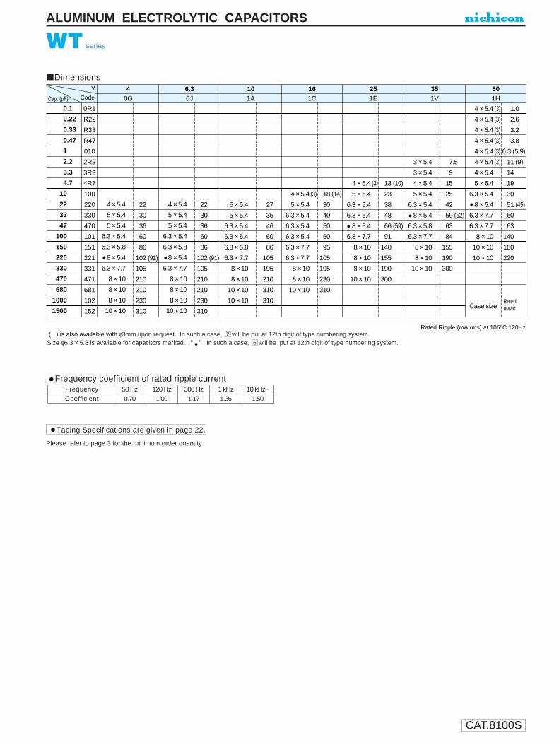
CAT.8100S
ALUMINUM ELECTROLYTIC CAPACITORS
WT series
Rated Ripple (mA rms) at 105°C 120Hz( ) is also available with φ3mm upon request. In such a case, will be put at 12th digit of type numbering system.
Size φ6.3 × 5.8 is available for capacitors marked. " " In such a case, will be put at 12th digit of type numbering system.6
2
Please refer to page 3 for the minimum order quantity.
Taping Specifications are given in page 22.
Frequency coefficient of rated ripple current
CoefficientFrequency 50 Hz 120 Hz 300 Hz 1 kHz 10 kHz~
0.70 1.00 1.17 1.36 1.50
Dimensions
0.1
0.22
0.33
0.47
1
2.2
3.3
4.7
10
22
33
47
100
150
220
330
470
680
1000
1500
0R1
R22
R33
R47
010
2R2
3R3
4R7
100
220
330
470
101
151
221
331
471
681
102
152
4 × 5.4
5 × 5.4
5 × 5.4
6.3 × 5.4
6.3 × 5.8
8 × 5.4
6.3 × 7.7
8 × 10
8 × 10
8 × 10
10 × 10
22
30
36
60
86
102 (91)
105
210
210
230
310
0G
V 40J6.3
1A10
1C16
1E25
1V35
1H50
4 × 5.4
5 × 5.4
5 × 5.4
6.3 × 5.4
6.3 × 5.8
8 × 5.4
6.3 × 7.7
8 × 10
8 × 10
8 × 10
10 × 10
5 × 5.4
5 × 5.4
6.3 × 5.4
6.3 × 5.4
6.3 × 5.8
6.3 × 7.7
8 × 10
8 × 10
10 × 10
10 × 10
4 × 5.4 (3)
5 × 5.4
6.3 × 5.4
6.3 × 5.4
6.3 × 5.4
6.3 × 7.7
6.3 × 7.7
8 × 10
8 × 10
10 × 10
4 × 5.4 (3)
5 × 5.4
6.3 × 5.4
6.3 × 5.4
8 × 5.4
6.3 × 7.7
8 × 10
8 × 10
8 × 10
10 × 10
3 × 5.4
3 × 5.4
4 × 5.4
5 × 5.4
6.3 × 5.4
8 × 5.4
6.3 × 5.8
6.3 × 7.7
8 × 10
8 × 10
10 × 10
4 × 5.4 (3)
4 × 5.4 (3)
4 × 5.4 (3)
4 × 5.4 (3)
4 × 5.4 (3)
4 × 5.4 (3)
4 × 5.4
5 × 5.4
6.3 × 5.4
8 × 5.4
6.3 × 7.7
6.3 × 7.7
8 × 10
10 × 10
10 × 10
Case size
22
30
36
60
86
102 (91)
105
210
210
230
310
27
35
46
60
86
105
195
210
310
310
18 (14)
30
40
50
60
95
105
195
230
310
13 (10)
23
38
48
66 (59)
91
140
155
190
300
7.5
9
15
25
42
59 (52)
63
84
155
190
300
1.0
2.6
3.2
3.8
6.3 (5.9)
11 (9)
14
19
30
51 (45)
60
63
140
180
220
CodeCap. (µF)
Ratedripple

CAT.8100S
ALUMINUM ELECTROLYTIC CAPACITORS
U1
W2
X3
14
C5
16
07
08
M9
C10
R11
112
G13
B14
Configuration
Taping code
Case dia.code
Capacitance toleranc (±20%)
Rated Capacitance (10µF)
Rated voltage (16V)
Series name
Type
φD
3
4 ~ 8
Code
2
1
1. Voltage mark for 6.3V is 6V . In case of marking for φ3 units, “V” for rated voltage is omitted. 2. In case of marking for φ3 units, Lot No.is expressed by a digit (month code).
0.5 ~ 0.8
Capacitance
1 Voltage2 Lot No.
X2
10 16V
Plastic platform0.3 MAX.
5.4 +0.1–0.2
φD±0
.5
B±0
.2
C±0.2
0.5
MA
X.
A±0
.2
A±0
.2
E
Positive
Negative
φD 3
A
B
C
E
1.5
3.3
3.3
0.8
1.8
4.3
4.3
1.0
2.1
5.3
5.3
1.3
2.4
6.6
6.6
2.2
4 5
(mm)
6.3
3.3
8.3
8.3
2.3
8
WX series
5.5mmL Chip Type
Chip type with 5.5mm height.Designed for surface mounting on high density PC board.Applicable to automatic mounting machine using carrier tape.Load life of 2000 hours at 85°C.
Chip Type Type numbering system (Example : 16V 10µF)
Specifications
Category Temperature Range
Rated Voltage Range
Rated Capacitance Range
Capacitance Tolerance
Leakage Current
tan δ
Stability at Low Temperature
Endurance
Resistance to soldering
heat
Marking
Performance CharacteristicsItem
–40 ~ +85°C
4 ~ 50V
0.1 ~ 330µF
±20% at 120Hz, 20°C
After 2 minutes' application of rated voltage, leakage current is not more than 0.01CV or 3 (µA) ,whichever is greater.
Black print on the case top.
Values in ( ) applicable to WR, φ3 case size.
Measurement frequency : 120Hz
After 2000 hours' application of rated voltageat 85°C, capacitors meet the characteristicrequirements listed at right.
Shelf LifeAfter leaving capacitors under no load at 85°C for 1000 hours, they meet the specified value for endurance characteristics listed above.
The capacitors shall be kept on the hot plate maintained at 250°Cfor 30 seconds. After removing from the hot plate and restored at room temperature, they meet the characteristic requirements listed at right.
Rated voltage (V) tan δ (MAX.)
6.3
0.26 (0.30) 10
0.20 (0.24) 16
0.16 (0.19) 25
0.14 (0.16) 35
0.12 (0.14) 50
0.12 (0.14)
Z–25°C / Z+20°C
Z–40°C / Z+20°C
Rated voltage (V)
Impedance ratioZT / Z20 (MAX.)
4
7
15
6.3
4
8
10
3
8
16
2
4
25
2
4
35
2
3
50
2
3
WX
WT
Bi-Polarized Low ProfileWP ZS
Measurement frequency : 120Hz, Temperature : 20°C
4
0.35 (0.40)
HighTemperature
Capacitance change
Leakage Current
tan δWithin ±20% of initial value (Within ±25% for 4 V and φ3,WR series units)200% or less of initial specified value
Initial specifed value or less
Capacitance change
Leakage current
tan δWithin ±10% of initial valueInitial specified value or lessInitial specified value or less
Dimension table in next page.
• The lead-free product is also available upon request.In this case, will be put at 11th digit of type numbering system.
• In the case of size φ3 in ( ),parentheses, use WX in the 2nd and 3rd
digit and put a in the 12th digit of type numbering system.2
L

CAT.8100S
WX series
Dimensions
0.1
0.22
0.33
0.47
1
2.2
3.3
4.7
10
22
33
47
56
100
150
220
330
0R1
R22
R33
R47
010
2R2
3R3
4R7
100
220
330
470
560
101
151
221
331
3
4
4
5
5
6.3
6.3
8
019
028
033
042
056
079
096
145
4 (3)
5
5
6.3
6.3
6.3
8
8
28 (21)
37 (34)
45 (40)
52 (46)
70 (47)
71
110 (74)
170
5
5
6.3
6.3
6.3
8
8
33 (30)
41 (34)
52 (47)
57 (50)
76 (54)
111 (76)
135
4 (3)
5
6.3
6.3
6.3
6.3
23 (18)
37 (30)
49 (44)
58 (52)
63 (57)
86
4 (3)
5
6.3
6.3
8
8
8
16 (12)
27 (24)
42 (38)
52 (46)
70 (60)
76 (65)
110
3
3
4
5
6.3
8
8
8.4
10
18
29 (24)
46 (39)
62 (53)
80
4 (3)
4 (3)
4 (3)
4 (3)
4 (3)
4 (3)
4
5
6.3
8
8
Case size
1.0
2.0
2.8
4.0
8.4 (8.0)
13 (10)
17
20 (18)
33 (30)
52 (43)
71
Ratedripple
40G
6.30J
101A
161C
251E
351V
501H
V
CodeCap. (µF)
( ) is also available with φ3mm upon request. Rated Ripple (mA rms) at 85°C 120Hz
( ) = φ3 units and WR Series
Size φ4 is available for capacitors marked. " "Size φ5 is available for capacitors marked. " " In such a case, will be put at 2nd and 3rd digit of type numbering system.Size φ6.3 is available for capacitors marked. " "
RW
ALUMINUM ELECTROLYTIC CAPACITORS
Please refer to page 3 for the minimum order quantity.
Taping Specifications are given in page 22.
Frequency coefficient of rated ripple current
CoefficientFrequency 50 Hz 120 Hz 300 Hz 1 kHz 10 kHz~
0.70 1.00 1.17 1.36 1.50
• In the case of size φ3 in ( ),parentheses, use WX at 2nd and 3rd digit and put at the 12th digit of type numbering system.2

CAT.8100S
PLASTIC FILM CAPACITORS
XD series (For High Frequency and Large Current Applications)
Metallized Polypropylene Film Capacitor
Specifications
Ideal for high frequency applications due to a metallized polypropylene film dielectric which exhibitssuperior operative characteristics with minimal loss at high frequency.Electrode has minimal inductance because of non-inductive construction.Finished by inner dipping with liquid epoxy resin and outer coating with flame-retardant epoxy resin, thosedouble coating gives superior characteristics against moisture.
ApplicationsHigh frequency & large current circuit applications(resonant circuit, change & discharge circuit & etc.)
Item Performance Characteristics
Category Temperature Range –40 ~ +105˚C (Rated temperature : 85˚C)
Rated Voltage (UR) 400, 630V.D.C
Rated Capacitance Range 0.0068 ~ 0.1µF
Capacitance Tolerance ±10% (K)
Directric Loss Tangent 0.1% or less (at 1kHz)
Insulation Resistance C <= 0.33µF 30000 MΩ or more C > 0.33µF 10000 ΩF or more
Encapsulation Flame retardant epoxy resin
Category voltage = UR × 0.7
Dimensions
Drawing
Q1
X2
D3
24
J5
16
07
38
K9
R10
P T11 12 AC usage applicable
Straight lead type :AC usage applicableCut/formed lead type :
Capacitance tolerance (K : ±10%)
Configuration (RP : Polypropylene film, Soldered CP wire)
Rated Capacitance (0.01µF)
Rated voltage (630V)
Series name
Type
Type numbering system (Example : 630V 0.01µF)
7FM7FR( )
T
Straight lead type
WMAX.
1MAX.
φ d ± 0.05
T MAX.
P±1.5
25MIN.
HMAX.
Cut/ formed lead type
WMAX.
F±1.5
4.5±0.5
5MAX.
HMAX.
φ d ± 0.05
TMAX.
F Size Code
15.0 7FM
20.0 7FR
Withstand VoltageBetween Terminals : Rated Voltage × 175%, 1 ~ 5 secs.Between Terminals
Maximum allowable voltage to high frequency rangeMaximum allowable voltage differs by frequency and it is reguested to
refer the graphs shown in next page. Effective values for 200 kHz sine wave
is indicated in the list below.
400VDC (200VAC) (2G) Permissible Effective Value (200kHz) 630VDC (300VAC) (2J) Permissible Effective Value (200kHz)
Cap. T W H d P F Ve Ie T W H d P F Ve Ie
0.0068 682 6.0 19 13.5 0.8 15 15 66 0.57
0.01 103 5.4 19 12.9 0.8 15 15 52 0.66 6.8 19 14.3 0.8 15 15 58 0.74
0.015 153 6.1 19 13.6 0.8 15 15 45 0.85 7.9 19 15.4 0.8 15 15 51 0.87
0.022 223 7.0 19 14.5 0.8 15 15 39 1.10 9.3 19 16.8 0.8 15 15 45 1.26
0.033 333 8.2 19 15.7 0.8 15 15 35 1.46 7.7 24 17.6 0.8 20 20 41 1.71
0.047 473 9.6 19 17.1 0.8 15 15 31 1.86 10.5 24 20.3 0.8 20 20 38 2.29
0.068 683 7.8 24 17.7 0.8 20 20 27 2.38 12.5 24 22.3 0.8 20 20 34 2.94
0.1 104 9.3 24 19.1 0.8 20 20 24 3.10
V(Code)
Size(µF)
Code
F : lead pitch for cut / formed lead wires

CAT.8100S
PLASTIC FILM CAPACITORS
Rated 400VDC
Maximum permissible voltage used at higher frequency range (Sine Wave)
Voltage
Rated 400VDCCurrent Current
∆C/C(%)
(%) (%)
(%)
–2
0
2
Rated 630VDCVoltage
Rated 630VDC
Typical Characteristic Curves
Temperature Characteristics Frequency Characteristics
Remarks : Typical curves are as shown below.(Slightly different depending on individual rating.)
Capacitance change
Temperature (%)–20–40 0 20 40 60 80 100
tan δ
0.004
0.002
0.006
tan δ
Temperature (˚C)–20–40 0 20 40 60 80 100
∆C/C
–2
0
2
Capacitance change
Frequency (Hz)
tan δ tan δ
103102 104 105 106
Frequency (Hz)103102 104 105 106
0.1
1.0
0.01
0.001
Frequency (Hz) Frequency (Hz)
Frequency (Hz) Frequency (Hz)
(V) (V)
100
0.01µF
0.10µF
10
(A)
0.10µF
0.01µF
103102 104 105 106
100
0.0068µF
0.068µF
10
(A)
0.068µF
0.0068µF
103102 104 105 106
103102 104 105 106 103102 104 105 106
10.0
1.0
0.10
0.01
10.0
1.0
0.10
0.01
XD series

CAT.8100S
PLASTIC FILM CAPACITORS
Ideal for high frequency applications due to a metallized polypropylene film dielectric which exhibitssuperior operative characteristics with minimal loss at high frequency.Self-healing electrode and non-inductive construction provide excellent characteristics in minimal inductance having better with standing voltage capability.Finished by inner dipping with liquid epoxy resin and outer coating with flame-retardant epoxy resin, those double coating gives superior characteristics against moisture.
ApplicationHigh frequency circuit, general electronic circuit and etc.
AC rated voltage (Operating at 50 / 60Hz AC circuit) shall be as followsHowever, do not use this product for across-the-line applications.
When used in high frequency circuit, refer to Table 2 and 4 for the valuesof effective voltage, current and effective VA, shown in pages 227, 230.
XF series (For High Frequency Applications)
Metallized Polypropylene Film Capacitor
Drawing
Specifications
Category Temperature Range
Rated Voltage (UR)
Rated Capacitance Range
Capacitance Tolerance
Dielectric Loss Tangent
Insulation Resistance
Withstand Voltage
Encapsulation
–40 ~ +105˚C (Rated temperature : 85˚C)
250, 400, 630, 800V.D.C.
0.01 ~ 3.3µF
±5% (J), ±10% (K)
0.1% or less (at 1kHz 20˚C)
C <= 0.33µF : 30000 MΩ or more C > 0.33µF : 10000 ΩF or more
Between Terminals : Rated Voltage × 175%, 1 ~ 5 secs.Between Terminals and Coverage : Rated Voltage × 200%, 1 ~ 5 secs.
Flame retardant epoxy resin
Performance CharacteristicsItem
Q1
X2
F3
24
J5
16
07
38
K9
R10
P11
T12
Configuration (RP : Polypropylene, Soldered CP wire)
AC usage applicable Straight lead type : TAC usage applicableCut / formed lead type :
Capacitance tolerance (J : ±5% K : ±10%)
Rated Capacitance (0.01µF)
Rated voltage (630V)
Series name
Type
F size
12.5
17.5
22.5
Code
7FL
7FP
7FT
27.5 7FX
Straight lead type. Cut / formed lead type.
W MAX
P±1.5
1.5MAX
25 MIN
H+1.0MAX
φd ± 0.05
T MAX W MAX T MAX
F±1.5
φd ± 0.054.5 ± 0.5
5 MAX
H+1.0MAX
Type numbering system (Example : 630V 0.01µF)
AC Rated Voltage
Category voltage = UR × 0.7
DC Rated VoltageAC Rated Voltage
250VDC125VAC
400VDC160VAC
630VDC200VAC
800VDC250VAC
Dimensions Unit : mm
F : lead pitch for cut / formed lead wires
V (Code)
Cap.(µF) Size T W H d P F
0.01 103
0.015 153
0.022 223
0.033 333
0.047 473 5.6 16.0 9.6 0.6 12.5 12.5
0.068 683 6.1 16.0 10.2 0.6 12.5 12.5
0.1 104 6.8 16.0 10.9 0.6 12.5 12.5
0.15 154 7.7 16.0 11.8 0.6 12.5 12.5
0.22 224 7.4 21.0 11.4 0.6 17.5 17.5
0.33 334 8.5 21.0 12.6 0.6 17.5 17.5
0.47 474 9.4 21.0 14.1 0.6 17.5 17.5
0.68 684 10.3 21.0 16.5 0.6 17.5 17.5
1.0 105 9.9 26.5 18.2 0.8 22.5 22.5
1.5 155 11.8 26.5 20.2 0.8 22.5 22.5
2.2 225 12.6 31.5 20.9 0.8 27.5 27.5
3.3 335 14.5 31.5 24.4 0.8 27.5 27.5
400VDC (2G)
T W H d P F
5.8 16.0 9.4 0.6 12.5 12.5
6.5 16.0 10.6 0.6 12.5 12.5
7.2 16.0 11.3 0.6 12.5 12.5
8.2 16.0 12.3 0.6 12.5 12.5
7.6 21.0 11.7 0.6 17.5 17.5
8.6 21.0 13.3 0.6 17.5 17.5
9.2 21.0 15.5 0.6 17.5 17.5
11.1 21.0 17.3 0.6 17.5 17.5
10.4 26.5 18.7 0.8 22.5 22.5
12.3 26.5 20.6 0.8 22.5 22.5
13.0 31.5 21.3 0.8 27.5 27.5
14.9 31.5 24.9 0.8 27.5 27.5
630VDC (2J)
T W H d P F
5.5 16.0 9.6 0.6 12.5 12.5
6.1 16.0 10.1 0.6 12.5 12.5
6.8 16.0 10.8 0.6 12.5 12.5
7.5 16.0 11.2 0.6 12.5 12.5
6.7 21.0 11.4 0.6 17.5 17.5
7.1 21.0 13.4 0.6 17.5 17.5
8.2 21.0 14.4 0.6 17.5 17.5
9.6 21.0 15.9 0.6 17.5 17.5
9.0 26.5 17.3 0.8 22.5 22.5
10.7 26.5 19.1 0.8 22.5 22.5
11.1 31.5 19.4 0.8 27.5 27.5
13.2 31.5 21.5 0.8 27.5 27.5
800VDC (2K)
T W H d P F
6.2 16.0 10.3 0.6 12.5 12.5
7.0 16.0 11.1 0.6 12.5 12.5
8.0 16.0 12.1 0.6 12.5 12.5
7.1 21.0 11.8 0.6 17.5 17.5
7.5 21.0 13.8 0.6 17.5 17.5
8.7 21.0 14.9 0.6 17.5 17.5
9.6 21.0 17.5 0.6 17.5 17.5
9.6 26.5 18.0 0.8 22.5 22.5
11.5 26.5 19.8 0.8 22.5 22.5
12.1 31.5 20.5 0.8 27.5 27.5
13.7 31.5 23.7 0.8 27.5 27.5
Code
250VDC (2E)
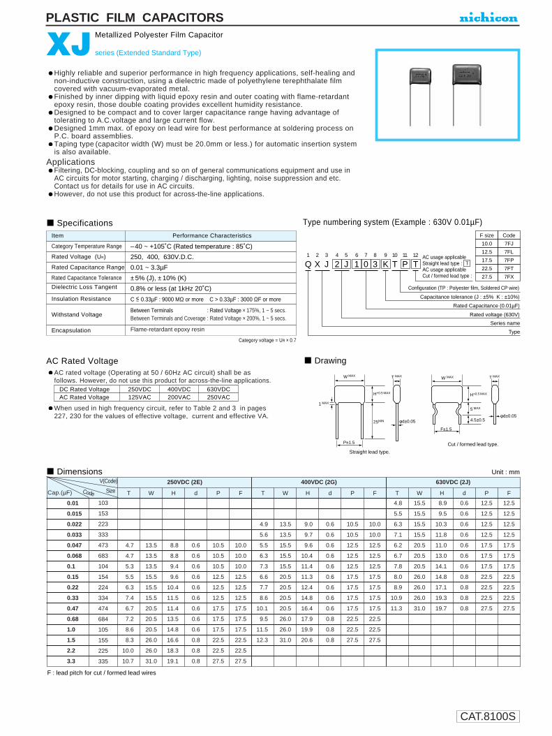
CAT.8100S
PLASTIC FILM CAPACITORS
Highly reliable and superior performance in high frequency applications, self-healing andnon-inductive construction, using a dielectric made of polyethylene terephthalate filmcovered with vacuum-evaporated metal.Finished by inner dipping with liquid epoxy resin and outer coating with flame-retardantepoxy resin, those double coating provides excellent humidity resistance.Designed to be compact and to cover larger capacitance range having advantage oftolerating to A.C.voltage and large current flow.Designed 1mm max. of epoxy on lead wire for best performance at soldering process onP.C. board assemblies.Taping type (capacitor width (W) must be 20.0mm or less.) for automatic insertion systemis also available.
ApplicationsFiltering, DC-blocking, coupling and so on of general communications equipment and use inAC circuits for motor starting, charging / discharging, lighting, noise suppression and etc.Contact us for details for use in AC circuits.However, do not use this product for across-the-line applications.
AC rated voltage (Operating at 50 / 60Hz AC circuit) shall be asfollows. However, do not use this product for across-the-line applications.
When used in high frequency circuit, refer to Table 2 and 3 in pages227, 230 for the values of effective voltage, current and effective VA.
XJ series (Extended Standard Type)
Metallized Polyester Film Capacitor
Drawing
Specifications
Category Temperature Range
Rated Voltage (UR)
Rated Capacitance Range
Rated Capacitance Tolerance
Dielectric Loss Tangent
Insulation Resistance
Withstand Voltage
Encapsulation
–40 ~ +105˚C (Rated temperature : 85˚C)
250, 400, 630V.D.C.
0.01 ~ 3.3µF
±5% (J), ±10% (K)
0.8% or less (at 1kHz 20˚C)
C <= 0.33µF : 9000 MΩ or more C > 0.33µF : 3000 ΩF or more
Between Terminals : Rated Voltage × 175%, 1 ~ 5 secs.Between Terminals and Coverage : Rated Voltage × 200%, 1 ~ 5 secs.
Flame-retardant epoxy resin
Performance CharacteristicsItem
Dimensions Unit : mm
Type numbering system (Example : 630V 0.01µF)
AC Rated Voltage
DC Rated VoltageAC Rated Voltage
250VDC125VAC
400VDC200VAC
630VDC250VAC
Category voltage = UR × 0.7
F : lead pitch for cut / formed lead wires
Q1
X2
J3
24
J5
16
07
38
K9
T10
P11
T12
Configuration (TP : Polyester film, Soldered CP wire)
AC usage applicable Straight lead type : TAC usage applicableCut / formed lead type :
Capacitance tolerance (J : ±5% K : ±10%)
Rated Capacitance (0.01µF)
Rated voltage (630V)
Series name
Type
F size
10.0
12.5
17.5
22.5
Code
7FJ
7FL
7FP
7FT
27.5 7FX
Straight lead type.
Cut / formed lead type.
W MAXW MAX
F±1.5
P±1.5
1 MAX
25MIN
H+0.5 MAX
φd±0.05
T MAX
4.5±0.5
5 MAX
H+0.5 MAX
φd±0.05
T MAX
0.01
0.015
0.022
0.033
0.047
0.068
0.1
0.15
0.22
0.33
0.47
0.68
1.0
1.5
2.2
3.3
103
153
223
333
473
683
104
154
224
334
474
684
105
155
225
335
4.7
4.7
5.3
5.5
6.3
7.4
6.7
7.2
8.6
8.3
10.0
10.7
13.5
13.5
13.5
15.5
15.5
15.5
20.5
20.5
20.5
26.0
26.0
31.0
8.8
8.8
9.4
9.6
10.4
11.5
11.4
13.5
14.8
16.6
18.3
19.1
0.6
0.6
0.6
0.6
0.6
0.6
0.6
0.6
0.6
0.8
0.8
0.8
10.5
10.5
10.5
12.5
12.5
12.5
17.5
17.5
17.5
22.5
22.5
27.5
10.0
10.0
10.0
12.5
12.5
12.5
17.5
17.5
17.5
22.5
22.5
27.5
4.9
5.6
5.5
6.3
7.3
6.6
7.7
8.6
10.1
9.5
11.5
12.3
13.5
13.5
15.5
15.5
15.5
20.5
20.5
20.5
20.5
26.0
26.0
31.0
9.0
9.7
9.6
10.4
11.4
11.3
12.4
14.8
16.4
17.9
19.9
20.6
0.6
0.6
0.6
0.6
0.6
0.6
0.6
0.6
0.6
0.8
0.8
0.8
10.5
10.5
12.5
12.5
12.5
17.5
17.5
17.5
17.5
22.5
22.5
27.5
10.0
10.0
12.5
12.5
12.5
17.5
17.5
17.5
17.5
22.5
22.5
27.5
4.8
5.5
6.3
7.1
6.2
6.7
7.8
8.0
8.9
10.9
11.3
15.5
15.5
15.5
15.5
20.5
20.5
20.5
26.0
26.0
26.0
31.0
8.9
9.5
10.3
11.8
11.0
13.0
14.1
14.8
17.1
19.3
19.7
0.6
0.6
0.6
0.6
0.6
0.6
0.6
0.8
0.8
0.8
0.8
12.5
12.5
12.5
12.5
17.5
17.5
17.5
22.5
22.5
22.5
27.5
12.5
12.5
12.5
12.5
17.5
17.5
17.5
22.5
22.5
22.5
27.5
T W H d P F T W H d P F T W H d
250VDC (2E) 400VDC (2G) 630VDC (2J)V(Code)
P FCap.(µF) Code Size
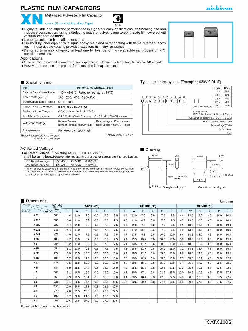
CAT.8100S
–40 ~ +105˚C (Rated temperature : 85˚C)
PLASTIC FILM CAPACITORS
AC rated voltage (Operating at 50 / 60Hz AC circuit)shall be as follows.However, do not use this product for across-the-line applications.
When operating capacitors in the high frequency circuit, maximum permissible value (VAC) canbe calculated from table 2, provided that the effective current (le) and the effective VA (Ve x Ve)shall not exceed the values specified in table 5.
XN series (Extended Standard Type)
Metallized Polyester Film Capacitor
Drawing
Specifications
Category Temperature Range
Rated Voltage (UR)
RatedCapacitance Range
Capacitance Tolerance
Dielectric Loss Tangent
Insulation Resistance
Withstand Voltage
Encapsulation
100, 250, 400, 630V.D.C.
0.01 ~ 10µF
±5% (J) , ±10% (K)
0.8% or less (at 1kHz 20˚C)
C <= 0.33µF : 9000 MΩ or more C > 0.33µF : 3000 ΩF or more
Between Terminals : Rated Voltage × 175%, 1 ~ 5 secs.Between Terminals and Coverage : Rated Voltage × 200%, 1 ~ 5 secs.
Flame retardant epoxy resin
Performance CharacteristicsItem
Dimensions Unit : mm
AC Rated Voltage
DC Rated VoltageAC Rated Voltage
250VDC125VAC
400VDC200VAC
630VDC250VAC
Category voltage = UR × 0.7
F : lead pitch for cut / formed lead wires
V(Code)
Cap.(µF) Size
0.01 103
0.015 153
0.022 223
0.033 333
0.047 473
0.068 683
0.1 104
0.15 154
0.22 224
0.33 334
0.47 474
0.68 684
1.0 105
1.5 155
2.2 225
3.3 335
4.7 475
6.8 685
10.0 106
250VDC (2E)
T W H d P F
4.4 11.0 7.6 0.6 7.5 7.5
5.0 11.0 8.2 0.6 7.5 7.5
4.4 11.0 8.0 0.6 7.5 7.5
4.4 11.0 8.0 0.6 7.5 7.5
4.0 11.0 7.6 0.6 7.5 7.5
4.7 11.0 8.2 0.6 7.5 7.5
5.2 11.0 8.9 0.6 7.5 7.5
6.1 11.0 9.8 0.6 7.5 7.5
5.9 13.5 10.5 0.6 10.0 10.0
6.7 13.5 11.9 0.6 10.0 10.0
5.5 18.5 12.3 0.6 15.0 15.0
6.0 18.5 14.3 0.6 15.0 15.0
7.1 18.5 15.5 0.6 15.0 15.0
9.9 18.5 15.1 0.6 15.0 15.0
8.1 25.5 16.5 0.8 22.5 22.5
10.0 25.5 18.3 0.8 22.5 22.5
12.0 25.5 20.3 0.8 22.5 22.5
12.7 30.5 21.3 0.8 27.5 27.5
15.6 30.5 24.2 0.8 27.5 27.5
400VDC (2G)
T W H d P F
4.4 11.0 7.6 0.6 7.5 7.5
5.0 11.0 8.2 0.6 7.5 7.5
4.3 11.0 7.9 0.6 7.5 7.5
4.9 11.0 8.6 0.6 7.5 7.5
4.7 13.5 9.3 0.6 10.0 10.0
5.4 13.5 10.0 0.6 10.0 10.0
6.1 13.5 11.2 0.6 10.0 10.0
5.1 18.5 11.9 0.6 15.0 15.0
5.9 18.5 12.7 0.6 15.0 15.0
7.6 18.5 12.8 0.6 15.0 15.0
8.3 18.5 15.1 0.6 15.0 15.0
7.2 25.5 15.6 0.8 22.5 22.5
8.7 25.5 17.1 0.8 22.5 22.5
9.4 30.5 18.0 0.8 27.5 27.5
11.5 30.5 20.0 0.8 27.5 27.5
630VDC (2J)
T W H d P F
4.4 13.5 9.0 0.6 10.0 10.0
4.7 13.5 9.3 0.6 10.0 10.0
5.1 13.5 10.3 0.6 10.0 10.0
5.9 13.5 11.1 0.6 10.0 10.0
6.4 13.5 13.2 0.6 10.0 10.0
5.8 18.5 11.0 0.6 15.0 15.0
6.4 18.5 13.2 0.6 15.0 15.0
7.1 18.5 15.4 0.6 15.0 15.0
9.6 18.5 14.8 0.6 15.0 15.0
7.9 25.5 16.2 0.8 22.5 22.5
9.4 25.5 17.7 0.8 22.5 22.5
11.3 25.5 19.6 0.8 22.5 22.5
12.0 30.5 20.5 0.8 27.5 27.5
14.8 30.5 23.3 0.8 27.5 27.5
18.5 30.5 27.5 0.8 27.5 27.5
Code
Except for 250VDC 0.01 ~ 0.15µFExcept for 400VDC 0.01 ~ 0.033µF
Highly reliable and superior performance in high frequency applications, self-healing and non-inductive construction, using a dielectric made of polyethylene terephthalate film covered withvacuum-evaporated metal.Large capacitance in small dimensions.Finished by inner dipping with liquid epoxy resin and outer coating with flame-retardant epoxyresin, those double coating provides excellent humidity resistance.Designed 1mm max. of epoxy on lead wire for best performance at soldering process on P.C.board assemblies.
ApplicationsGeneral electronic and communications equipment. Contact us for details for use in AC circuits.However, do not use this product for across-the-line applications.
Q1
X2
N3
24
J5
16
07
38
K9
T10
P11
Configuration(TP : Polyester film, Soldered CP wire)
Cut / formed lead type
Capacitance tolerance (J : ±5% K : ±10%)
Rated Capacitance (0.01µF)
Rated voltage (630V)
Series name
Type
F size
7.5
10.0
15.0
Code
7FG
7FJ
7FM
22.5 7FT
27.5 7FX
Type numbering system (Example : 630V 0.01µF)
Straight lead type. Cut / formed lead type.
W MAXW MAX T MAX
F±1.5
P±1.5
1MAX
25MIN
H+0.5MAX
φd ± 0.05φd ± 0.05
TMAX
4.5 ± 0.5
5MAX
H+0.5MAX

CAT.8100S
PLASTIC FILM CAPACITORS
Q1
X2
U3
24
E5
16
07
48
K9
T10
P11
T12
Configuration (TP:Polyester film, Soldered CP wire)
AC usage applicable Straight lead type: TAC usage applicable Cut/formed lead type:
Capacitance tolerance (±10% : K)
Rated Capacitance (0.1µF) Rated voltage (250V)
Series name
Type
F size
7.5
10.0
15.0
Code
7FG
7FJ
7FM
22.5 7FT
Straight lead type. Cut / formed lead type.
WMAX TMAX
F ±1.5
1.5MAX
φd ± 0.05φd ± 0.05
TMAX
4.5 ± 0.5
5MAX
H MAX HMAX
W MAX
25MIN
P ±1.5
XU series for 105˚C (Electrical Appliance and Material ControlLaw(Japan) approved for AC power source)
Metallized Polyester Film Capacitor
Highly reliable and superior in high frequency applications, self-healing and non-inductive construction, using a dielectric of metallized polyester film.Finished by inner dipping, with liquid epoxy resin and outer coating with flame-retardant epoxy resin, those double coatings provide excellent humidity resistance.Designed in a small and compact size, but yet with higher capacitance, for high density mounting.
Characteristis of capacitors to be used in the power source line (primary sid) are spceified in the Safety Standards in pages from 231 to 232 for correct application.
Specifications Type numbering system (Example : 250VAC 0.1µF)
Performance Characteristics
Category Temperature Range
Rated Voltage
Rated Capacitance Range
Capacitance Tolerance
Dielectric Loss Tangent
Insulation Resistance
Withstand Voltage
Encapsulation
–40 ~ +105˚C
125, 250VAC
Safety performance A1 0.01 ~ 0.47µFSafety performance C1 0.01 ~ 1.0µF
±10% (K)
1.0% or less (at 1kHz 20˚C)
C <= 0.47µF 2000 MΩ or more C > 0.47µF 1000 ΩF or more
Flame-retardant epoxy resin
Between Terminals : Rated Voltage × 2.3VAC 1min. (Safety performance : A1)Rated Voltage × 1.75VAC 1 min. (Safety performance : C1)
Between Terminals Coverage : (Rated Voltage 125VAC) 1000VAC 1 min.(Rated Voltage 250VAC) 1500VAC 1 min.
Drawing
Safety performance
Dimensions
Symbol A1 C1
Connecting
Condition
Capacitance 0.01 ~ 0.47µF 0.1 ~ 1.0µF
Connected with load in parallel Connected with load in series
Z Z
Note : When using capacitors as an across-the-line capacitor, at least either one of the conditions
shown below has to be fulfilled:
1) A varistor of 2 times or below of rated voltage shall be connected with a capacitor in parallel.
2) Pulse of higher than rated voltage × 2 shall not be applied to both terminals of capacitor.
F : lead pitch for cut / formed lead wires.
Unit : mm
Item
125VAC (2B) 250VAC (2E)
T W H d P F T W H d P F
0.01 103 4.4 13.5 9.5 0.6 10.0 10.0
0.015 153 4.7 13.5 9.8 0.6 10.0 10.0
0.022 223 4.3 11.0 7.9 0.6 7.5 7.5 5.1 13.5 10.8 0.6 10.0 10.0
0.033 333 4.6 11.0 8.2 0.6 7.5 7.5 5.9 13.5 11.6 0.6 10.0 10.0
0.047 473 5.1 11.0 8.8 0.6 7.5 7.5 6.4 13.5 13.7 0.6 10.0 10.0
0.068 683 5.8 11.0 9.5 0.6 7.5 7.5 5.8 18.5 11.5 0.6 15.0 15.0
0.1 104 6.8 11.0 10.4 0.6 7.5 7.5 6.4 18.5 13.7 0.6 15.0 15.0
0.15 154 6.5 13.5 11.1 0.6 10.0 10.0 7.1 18.5 15.9 0.6 15.0 15.0
0.22 224 7.6 13.5 12.2 0.6 10.0 10.0 9.6 18.5 15.3 0.6 15.0 15.0
0.33 334 6.7 18.5 11.9 0.6 15.0 15.0 7.9 25.5 16.7 0.8 22.5 22.5
0.47 474 7.7 18.5 12.9 0.6 15.0 15.0 9.4 25.5 18.2 0.8 22.5 22.5
0.68 684 9.1 18.5 14.3 0.6 15.0 15.0
1.0 105 8.0 25.5 15.3 0.8 22.5 22.5
CodeCap.(µF) Size
V(Code)
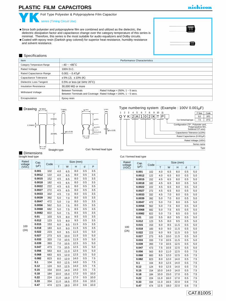
CAT.8100S
PLASTIC FILM CAPACITORS
Since both polyester and polypropylene film are combined and utilized as the dielectric, thedielectric dissipation factor and capacitance change over the category temperature of this series isminimial. Therefore, this series is the most suitable for audio equalizers and Dolby circuits.Coated with epoxy resin (Darkish gray colored) for superior heat resistance, humidity resistanceand solvent resistance.
YK series (Timing Circuit Use)
Foil Type Polyester & Polypropylene Film Capacitor
Drawing
Specifications
Category Temperature Range
Rated Voltage
Rated Capacitance Range
Capacitance Tolerance
Dielectric Loss Tangent
Insulation Resistance
Withstand Voltage
Encapsulation
–40 ~ +85˚C
100V.D.C.
0.001 ~ 0.47µF
±5% (J), ±10% (K)
0.5% or less (at 1kHz 20˚C)
30,000 MΩ or more
Between Terminals : Rated Voltage × 250%, 1 ~ 5 secs.Between Terminals and Coverage : Rated Voltage × 200%, 1 ~ 5 secs.
Epoxy resin
Performance CharacteristicsItem
Q1
Y2
K3
24
A5
16
07
28
K9
T10
P11
Configuration (TP : Polyester and,Polypropylene film,Soldered CP wire)
Cut / formed lead type :
Capacitance Tolerance (±10%)
Rated Capacitance (0.001µF)
Rated Voltage (100V)
Series name
Type
5.0
7.5
1FD
1FG
F Size Code
Straight type Cut / formed lead type
W MAX.W MAX.
F ±1.0
1.5 MAX.
φd ± 0.05
T MAX.
5.0 ± 0.5
6.0 MAX.
H MAX.
φd ± 0.05
T MAX.
P ±1.0
20 MIN.
H MAX.
Type numbering system (Example : 100V 0.001µF)
Straght lead type Cut / formed lead type
Code
100(2A)
102122152182222272332392472562682822103123153183223273333393473563683823104124154184224334474
0.0010.00120.00150.00180.00220.00270.00330.00390.00470.00560.00680.00820.010.0120.0150.0180.0220.0270.0330.0390.0470.0560.0680.0820.10.120.150.180.220.330.47
4.04.04.54.54.54.54.55.05.05.05.05.05.55.56.06.06.06.57.07.07.58.08.58.08.09.0
10.010.011.011.012.5
T W H d P
Ratedvoltage(VDC)
Cap.(µF)
Size (mm)
6.56.56.56.56.56.57.07.07.07.57.57.58.08.08.59.09.5
10.010.510.510.511.012.012.012.512.514.015.016.016.518.0
8.08.08.08.08.08.08.08.08.08.08.58.59.59.5
11.511.511.511.511.512.512.512.512.514.014.014.014.017.017.022.022.0
0.50.50.50.50.50.50.50.50.50.50.50.50.50.50.50.50.50.50.50.50.50.50.50.50.50.50.50.50.50.60.6
3.53.53.53.53.53.53.53.53.53.53.53.53.53.53.53.55.05.05.05.05.05.05.07.57.57.57.5
10.010.010.010.0
Code
100(2A)
102122152182222272332392472562682822103123153183223273333393473563683823104124154184224334474
0.0010.00120.00150.00180.00220.00270.00330.00390.00470.00560.00680.00820.010.0120.0150.0180.0220.0270.0330.0390.0470.0560.0680.0820.10.120.150.180.220.330.47
4.04.04.54.54.54.54.55.05.05.05.05.05.55.56.06.06.06.57.07.07.58.08.58.08.09.0
10.010.011.011.012.5
T W H d F
Ratedvoltage(VDC)
Cap.(µF)
Size (mm)
6.56.56.56.56.56.57.07.07.07.57.57.58.08.08.59.09.5
10.010.510.510.511.012.012.012.512.514.015.016.016.518.0
8.08.08.08.08.08.08.08.08.08.08.58.59.59.5
11.511.511.511.511.512.512.512.512.514.014.014.014.017.017.022.022.0
0.50.50.50.50.50.50.50.50.50.50.50.50.50.50.50.50.50.50.50.50.50.50.50.50.50.50.50.50.50.60.6
5.05.05.05.05.05.05.05.05.05.05.05.05.05.05.05.05.05.05.05.05.07.57.57.57.57.57.57.57.57.57.5
Dimensions
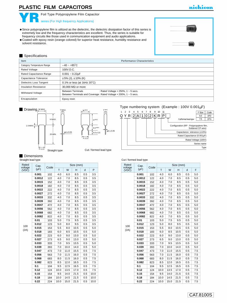
CAT.8100S
PLASTIC FILM CAPACITORS
Since polypropylene film is utilized as the dielectric, the dielectric dissipation factor of this series isextremely low and the frequency characteristics are excellent. Thus, the series is suitable forfrequency circuits like those used in communication equipment and audio applications.Coated with epoxy resin (orange colored) for superior heat resistance, humidity resistance andsolvent resistance.
YR series (For High frequency Applications)
Foil Type Polypropylene Film Capacitor
Drawing
Specifications
Q1
Y2
R3
24
A5
16
07
28
K9
R10
P11
Configuration (RP : Polypropylene film,Soldered CP wire)
Cut/formed lead-type :
Capacitance tolerance (±10%)
Rated Capacitance (0.001µF)
Rated Voltage (100V)
Series name
Type
5.0
7.5
1FD
1FG
F Size Code
Straight type Cut / formed lead type
W MAX.W MAX.
F ±1.0
1.5 MAX.
φd ± 0.05
T MAX.
5.0 ± 0.5
6.0 MAX.
H MAX.
φd ± 0.05
T MAX.
P ±1.0
20 MIN.
H MAX.
Dimensions
Type numbering system (Example : 100V 0.001µF)
Category Temperature Range
Rated Voltage
Rated Capacitance Range
Capacitance Tolerance
Dielectric Loss Tangent
Insulation Resistance
Withstand Voltage
Encapsulation
–40 ~ +85˚C
100V.D.C.
0.001 ~ 0.22µF
±5% (J), ±10% (K)
0.1% or less (at 1kHz 20˚C)
30,000 MΩ or more
Between Terminals : Rated Voltage × 250%, 1 ~ 5 secs.Between Terminals and Coverage : Rated Voltage × 200%, 1 ~ 5 secs.
Epoxy resin
Performance CharacteristicsItem
Straight lead type Cut / formed lead type
Code
100(2A)
102122152182222272332392472562682822103123153183223273333393473563683823104124154184224
0.0010.00120.00150.00180.00220.00270.00330.00390.00470.00560.00680.00820.010.0120.0150.0180.0220.0270.0330.0390.0470.0560.0680.0820.10.120.150.180.22
4.04.04.04.04.04.04.04.04.04.04.04.05.05.05.56.06.06.57.07.07.07.08.08.59.5
10.09.5
10.010.0
T W H d F
Ratedvoltage(VDC)
Cap.(µF)
Size (mm)
6.07.07.07.07.07.07.07.07.07.07.07.07.58.08.08.59.09.09.5
10.011.011.511.512.012.513.514.014.515.0
8.58.58.58.58.58.58.58.58.58.58.58.59.59.5
10.510.513.013.013.514.015.516.016.016.516.517.021.521.521.5
0.50.50.50.50.50.50.50.50.50.50.50.50.50.50.50.50.50.50.50.50.50.50.50.50.50.50.50.50.5
5.05.05.05.05.05.05.05.05.05.05.05.05.05.05.05.05.05.05.05.07.57.57.57.57.57.57.57.57.5
Code
100(2A)
102122152182222272332392472562682822103123153183223273333393473563683823104124154184224
0.0010.00120.00150.00180.00220.00270.00330.00390.00470.00560.00680.00820.010.0120.0150.0180.0220.0270.0330.0390.0470.0560.0680.0820.10.120.150.180.22
4.04.04.04.04.04.04.04.04.04.04.04.05.05.05.56.06.06.57.07.07.07.08.08.59.5
10.09.5
10.010.0
T W H d P
Ratedvoltage(VDC)
Cap.(µF)
Size (mm)
6.07.07.07.07.07.07.07.07.07.07.07.07.58.08.08.59.09.09.5
10.011.011.511.512.012.513.514.014.515.0
8.58.58.58.58.58.58.58.58.58.58.58.59.59.5
10.510.513.013.013.514.015.516.016.016.516.517.021.521.521.5
0.50.50.50.50.50.50.50.50.50.50.50.50.50.50.50.50.50.50.50.50.50.50.50.50.50.50.50.50.5
3.53.53.53.53.53.53.53.53.53.53.53.53.53.55.05.05.05.05.05.07.57.57.57.57.57.5
10.010.010.0
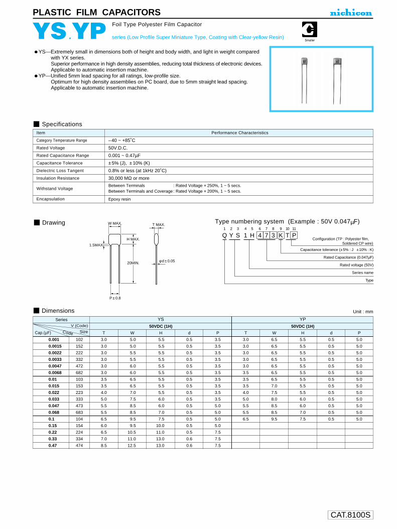
CAT.8100S
PLASTIC FILM CAPACITORS
YS—Extremely small in dimensions both of height and body width, and light in weight compared with YX series.Superior performance in high density assemblies, reducing total thickness of electronic devices.Applicable to automatic insertion machine.
YP—Unified 5mm lead spacing for all ratings, low-profile size.Optimum for high density assemblies on PC board, due to 5mm straight lead spacing.Applicable to automatic insertion machine.
YS .YP series (Low Profile Super Miniature Type, Coating with Clear-yellow Resin)
Foil Type Polyester Film Capacitor
Specifications
Category Temperature Range
Rated Voltage
Rated Capacitance Range
Capacitance Tolerance
Dielectric Loss Tangent
Insulation Resistance
Withstand Voltage
Encapsulation
–40 ~ +85˚C
50V.D.C.
0.001 ~ 0.47µF
±5% (J), ±10% (K)
0.8% or less (at 1kHz 20˚C)
30,000 MΩ or more
Between Terminals : Rated Voltage × 250%, 1 ~ 5 secs.Between Terminals and Coverage : Rated Voltage × 200%, 1 ~ 5 secs.
Epoxy resin
Performance CharacteristicsItem
Dimensions
Drawing
Q1
Y2
S3
14
H5
46
77
38
K9
T10
P11
Configuration (TP : Polyester film, Soldered CP wire)
Capacitance tolerance (±5% : J ±10% : K)
Rated Capacitance (0.047µF)
Rated voltage (50V)
Series name
Type
W MAX.
1.5MAX.
φ d ± 0.05
T MAX.
20MIN.
H MAX.
P ± 0.8
Type numbering system (Example : 50V 0.047µF)
Series YS YPV (Code) 50VDC (1H) 50VDC (1H)
Cap. .(µF) Size T W H d P T W H d P
0.001 102 3.0 5.0 5.5 0.5 3.5 3.0 6.5 5.5 0.5 5.0
0.0015 152 3.0 5.0 5.5 0.5 3.5 3.0 6.5 5.5 0.5 5.0
0.0022 222 3.0 5.5 5.5 0.5 3.5 3.0 6.5 5.5 0.5 5.0
0.0033 332 3.0 5.5 5.5 0.5 3.5 3.0 6.5 5.5 0.5 5.0
0.0047 472 3.0 6.0 5.5 0.5 3.5 3.0 6.5 5.5 0.5 5.0
0.0068 682 3.0 6.0 5.5 0.5 3.5 3.5 6.5 5.5 0.5 5.0
0.01 103 3.5 6.5 5.5 0.5 3.5 3.5 6.5 5.5 0.5 5.0
0.015 153 3.5 6.5 5.5 0.5 3.5 3.5 7.0 5.5 0.5 5.0
0.022 223 4.0 7.0 5.5 0.5 3.5 4.0 7.5 5.5 0.5 5.0
0.033 333 5.0 7.5 6.0 0.5 3.5 5.0 8.0 6.0 0.5 5.0
0.047 473 5.5 8.5 6.0 0.5 5.0 5.5 8.5 6.0 0.5 5.0
0.068 683 5.5 8.5 7.0 0.5 5.0 5.5 8.5 7.0 0.5 5.0
0.1 104 6.5 9.5 7.5 0.5 5.0 6.5 9.5 7.5 0.5 5.0
0.15 154 6.0 9.5 10.0 0.5 5.0
0.22 224 6.5 10.5 11.0 0.5 7.5
0.33 334 7.0 11.0 13.0 0.6 7.5
0.47 474 8.5 12.5 13.0 0.6 7.5
Unit : mm
Code

CAT.8100S
PLASTIC FILM CAPACITORS
Inductive construction, using a dielectric of polyester film together with aluminum foil.Coated with epoxy resin for superior heat resistance, humidity resistance and solvent resistance.Suited for use in commercial and industrial applications.Available for automatic insertion systems.
YX series (Standard type, Coating with Clear-yellow Resin)
Foil Type Polyester Film Capacitor
Drawing
Specifications
Category Temperature Range
Rated Voltage
Rated Capacitance Range
Capacitance Tolerance
Dielectric Loss Tangent
Insulation Resistance
Withstand Voltage
Encapsulation
–40 ~ +85˚C
50, 100V.D.C.
0.001~ 0.47µF
±5% (J), ±10% (K)
0.8% or less (at 1kHz 20˚C)
30,000 MΩ or more
Between Terminals : Rated Voltage × 250%, 1 ~ 5 secs.Between Terminals and Coverage : Rated Voltage × 200%, 1 ~ 5 secs.
Epoxy resin
Performance CharacteristicsItem
Q1
Y2
X3
14
H5
46
77
38
K9
T10
P11 12
Configuration (TP : Polyester film, Soldered CP wire)
Cut / formed lead type.
Capacitance tolerance (±5% : J ±10% : K)
Rated Capacitance (0.047µF)
Rated voltage (50V)
Series name
Type
F size
5.0
7.5
Code
1FD
1FG
Straight lead type. Cut / formed lead type.
W MAX
1.5MAX
T MAX
φ d ± 0.05
P
20MIN
H MAX
W MAX
F ±1.0
5.0 ± 0.5
6.0 MAX.
H MAX
φ d ± 0.05
T MAX
DimensionsUnit : mm
Type numbering system (Example : 50V 0.047µF)
V (Code) 50VDC (1H) 100VDC (2A)
Cap. .(µF) Size T W H d P F T W H d P F
0.001 102 2.5 5.0 7.0 0.5 3.5 ± 0.75 5.0 2.8 5.5 10.0 0.5 3.5±1.0 5.0
0.0012 122 2.5 5.0 7.0 0.5 3.5 5.0 2.8 5.5 10.5 0.5 3.5 5.0
0.0015 152 2.5 5.0 7.0 0.5 3.5 5.0 2.8 5.5 10.5 0.5 3.5 5.0
0.0018 182 2.5 5.5 7.0 0.5 3.5 5.0 2.8 5.5 10.5 0.5 3.5 5.0
0.0022 222 3.0 5.5 7.0 0.5 3.5 5.0 2.8 5.5 10.5 0.5 3.5 5.0
0.0027 272 3.0 5.5 7.0 0.5 3.5 5.0 2.8 5.5 10.5 0.5 3.5 5.0
0.0033 332 3.0 5.5 7.0 0.5 3.5 5.0 2.8 5.5 10.5 0.5 3.5 5.0
0.0039 392 3.0 5.5 7.0 0.5 3.5 5.0 2.8 5.5 10.5 0.5 3.5 5.0
0.0047 472 3.0 6.0 7.0 0.5 3.5 5.0 2.8 5.5 10.5 0.5 3.5 5.0
0.0056 562 3.0 6.0 7.0 0.5 3.5 5.0 2.8 6.0 10.5 0.5 5.0 ± 1.0 5.0
0.0068 682 3.0 6.0 7.0 0.5 3.5 5.0 2.8 6.0 10.5 0.5 5.0 5.0
0.0082 822 3.0 6.0 7.0 0.5 3.5 5.0 3.0 6.5 10.5 0.5 5.0 5.0
0.01 103 3.0 6.0 7.0 0.5 3.5 5.0 3.0 6.5 10.5 0.5 5.0 5.0
0.012 123 3.5 6.0 7.0 0.5 3.5 5.0 3.0 6.5 11.5 0.5 5.0 5.0
0.015 153 3.5 6.0 8.5 0.5 3.5 5.0 3.0 6.5 11.5 0.5 5.0 5.0
0.018 183 3.5 6.5 8.5 0.5 3.5 5.0 3.5 6.5 11.5 0.5 5.0 5.0
0.022 223 3.5 6.5 9.0 0.5 3.5 5.0 3.5 7.0 11.5 0.5 5.0 5.0
0.027 273 3.5 6.5 9.0 0.5 3.5 5.0 3.5 7.5 11.5 0.5 5.0 5.0
0.033 333 4.0 7.0 9.0 0.5 3.5 5.0 3.5 7.5 11.5 0.5 5.0 5.0
0.039 393 4.0 7.0 9.0 0.5 3.5 5.0 4.5 8.5 12.5 0.5 5.0 5.0
0.047 473 4.5 7.5 9.5 0.5 5.0 ± 1.0 5.0 4.5 8.5 12.5 0.5 5.0 5.0
0.056 563 4.5 7.5 9.5 0.5 5.0 5.0 4.5 9.5 12.5 0.5 7.5±1.0 7.5
0.068 683 4.5 8.0 9.5 0.5 5.0 5.0 4.5 9.5 12.5 0.5 7.5 7.5
0.082 823 5.5 8.0 9.5 0.5 5.0 5.0 5.5 11.0 12.5 0.5 7.5 7.5
0.1 104 5.5 9.0 10.5 0.5 5.0 5.0 5.5 11.0 12.5 0.5 7.5 7.5
0.12 124 5.5 9.0 10.5 0.5 5.0 5.0 6.0 12.5 14.0 0.5 10.0±1.0 7.5
0.15 154 6.5 10.0 12.0 0.5 5.0 5.0 6.0 12.5 14.0 0.5 10.0 7.5
0.18 184 6.5 10.5 12.0 0.5 5.0 5.0 7.0 14.0 14.0 0.5 10.0 7.5
0.22 224 6.5 11.0 12.0 0.5 7.5±1.0 7.5 7.0 14.0 14.0 0.5 10.0 7.5
0.27 274 8.0 12.5 14.5 0.6 7.5 7.5 8.0 14.5 17.0 0.6 10.0 7.5
0.33 334 8.0 12.5 14.5 0.6 7.5 7.5 8.0 14.5 17.0 0.6 10.0 7.5
0.39 394 9.5 14.0 15.0 0.6 7.5 7.5 9.5 16.5 17.0 0.6 10.0 7.5
0.47 474 9.5 14.0 15.0 0.6 7.5 7.5 9.5 16.5 17.0 0.6 10.0 7.5
Code
+1.0–1.2
+1.0–1.2
+1.0–1.2
+1.0–0.8
F : lead pitch for cut / formed lead wires.

CAT.8100S
ALUMINUM ELECTROLYTIC CAPACITORS
Please refer to page 3 for the minimum order quantity.
U1
Z2
D3
14
C5
16
07
08
M9
C10
R11
112
G13
B14
Configuration
Taping code
Capacitance tolerance (±20%)
Rated Capacitance (10µF)
Rated voltage (16V)
Series name
Type
Plastic platformSeries
Capacitance
Voltage
Lot No.
Positive
Negative
X2
10C
Z
D
0.3 MAX.
3.0 +0.2–0.1
D±
0.5
B±
0.2
C±0.2
0.5
MA
X.
A±
0.2
A
±0.
2
E
0.5 ~ 0.8
ZD series
3.0mmL Chip Type
Chip Type Type numbering system (Example : 16V 10µF)
Specifications
ZD
ZR
Dimensions
2.23.34.75.66.8
10223347
100
2R23R34R75R66R8100220330470101
4 205 285 336.3 56
5 285 376.3 456.3 70
5 336.3 41
5 236.3 37
4 74 114 165 185 206.3 27
Case Size
40G
6.30J
101A
161C
251E
V
Code
Taping Specifications are given in page 22.
φDABCE
41.84.34.31.0
52.15.35.31.3
6.32.46.66.62.2
(mm)
Cap. (µF)
Smaller
Stability at Low
Temperature
Resistance tosoldering heat
Z–40°C / Z+20°C
Category Temperature Range
Rated Voltage Range
Rated Capacitance Range
Capacitance Tolerance
Leakage Current
tan δ
Marking
Performance CharacteristicsItem
–40 ~ +85°C
4 ~ 25V
2.2 ~ 100µF
± 20% at 120Hz, 20°C
After 2 minutes' application of rated voltage, leakage current is not more than 0.01 CV or 3 (µA) , whichever is greater.
Rated voltage (V)
Rated voltage (V)
tan δ (MAX.)
4
0.50
4
7
15
6.3
0.40
6.3
4
8
10
0.30
10
3
8
16
0.24
16
2
4
25
0.19
25
2
4
120Hz20°C
120Hz
Impedance ratioZT / Z20 (MAX.)
Z–25°C / Z+20°C
After leaving capacitors under no load at 85°C for 1000 hours, they meet the specified value for endurance characteristics listed above.
The capacitors shall be kept on the hot plate maintained at 250°C for 30seconds. After removing from the hot plate and restored at room temperature,they meet the characteristic requirements listed at right.
Black print on the case top.
Shelf Life
EnduranceAfter 1000 hours' application of rated voltage at 85°C, capacitorsmeet the characteristic requirements listed at right.
Capacitance change
Leakage current
tan δWithin ±10% of initial valueInitial specified value or lessInitial specified value or less
Capacitance change
Leakage current
tan δWithin ±30% of initial value300% or less of initial specified valueInitial specified value or less
Frequency coefficient of rated ripple current
CoefficientFrequency 50 Hz 120 Hz 300 Hz 1 kHz 10 kHz~
0.70 1.00 1.17 1.36 1.50
VoltageV 4 6.3 10 16 25
Code g j A C E
Chip type with 3.0mmL height.Designed for surface mounting on high density PC board.Applicable to automatic mounting machine using carrier tape.
Ratedripple
Rated Ripple (mA rms) at 85°C 120Hz

CAT.8100S
ALUMINUM ELECTROLYTIC CAPACITORS
U1
Z2
E3
14
C5
16
07
08
M9
C10
R11
112
G13
B14
Configuration
Taping code
Capacitance tolerance (±20%)
Rated Capacitance (10µF)
Rated voltage (16V)
Series name
Type
Plastic platform
Series
Voltage
Capacitance
Lot No.
X2
10C ZE
0.3 MAX.
3.90 +0.05–0.2
φD±0
.5
B±0
.2
C±0.2
0.5
MA
X.
A±0
.2
A±0
.2
E
0.5 ~ 0.8
ZE series
3.95mmL MAX. Chip Type, Bi-polarized
Chip type with 3.95mmL MAX, height.Designed for surface mounting on high density PC board.Applicable to automatic mounting machine using carrier tape.
Chip Type Type numbering system (Example : 16V 10µF)
Specifications
Category Temperature Range
Rated Voltage Range
Rated Capacitance Range
Capacitance Tolerance
Leakage Current
tan δ
Stability at Low Temperature
Eudurance
Shelf Life
Marking
Performance CharacteristicsItem
–40 ~ +85°C
6.3 ~ 50V
0.1 ~ 47µF
±20% at 120Hz, 20°C
After 2 minutes' application of rated voltage, leakage current is not more than 0.05 CV or 10 (µA) , whichever is greater.
Black print on the case top.
Measurement frequency : 120Hz, Temperature : 20°C
Measurement frequency : 120Hz
After 1000 hours' application of rated voltageat 85°C with the polarity inverted every 250hours, capacitors meet the characteristicrequirements listed at right.After leaving capacitors under no load at 85°C for 1000 hours,they meet the specifiedvalue for endurance characteristics listed above.
Resistance to solderingheat
The capacitors shall be kept on the hot plate maintained at 250°Cfor 30 seconds. After removing from the hot plate and restoredat room temperature,they meet the characteristic requirements listed at right.
Z–25°C / Z+20°C
Z–40°C / Z+20°C
Rated voltage (V)
Impedance ratioZT / Z20 (MAX.)
6.3
4
8
10
3
8
16
2
4
25
2
4
35
2
3
50
2
3
Dimensions
0.10.220.330.4712.23.34.7
10223347
0R1R22R33R470102R23R34R7100220330470
56.36.3
283745
6.30J
101A
161C
251E
351V
501H
V
Code
46.36.3
173341
456.36.3
12233749
556.3
121627
4556.3
8.4161829
44444556.3
Case size
1.02.02.84.08.4
131720
Rated Ripple (mA rms) at 85°C 120Hz
φDABCE
41.84.34.31.0
52.15.35.31.3
6.32.46.66.62.2
(mm)
Cap. (µF)
Rated voltage (V) tan δ (MAX.)
6.3
0.30
10
0.24
16
0.20
25
0.18
35
0.16
50
0.16
Capacitance change
Leakage current
tan δWithin ±10% of initial valueInitial specified value or lessInitial specified value or less
Capacitance change
Leakage current
tan δWithin ±30% of initial value300% or less of initial specified valueInitial specified value or less
Ratedripple
Frequency coefficient of rated ripple current
CoefficientFrequency 50 Hz 120 Hz 300 Hz 1 kHz 10 kHz~
0.70 1.00 1.17 1.36 1.50 Please refer to page 3 for the minimum order quantity.
Taping Specifications are given in page 22.
ZE
ZP
Smaller
VoltageV 6.3 10 16 25 35 50
Code j A C E V H

CAT.8100S
ALUMINUM ELECTROLYTIC CAPACITORS
Please refer to page 3 for the minimum order quantity.
U1
Z2
G3
14
C5
16
07
08
M9
C10
R11
112
G13
B14
Configuration
Taping code
Capacitance tolerance (±20%)
Rated Capacitance (10µF)
Rated voltage (16V)
Series name
Type
Plastic platformSeries
Capacitance
Voltage
Lot No.
Positive
Negative
X2
10C
ZG
0.3 MAX.
3.90 +0.05–0.2
φD±0
.5
B±0
.2
C±0.2
0.5
MA
X.
A±0
.2
A±0
.2
E
0.5 ~ 0.8
ZG series
3.95mmL MAX. Chip Type,Wide Temperature Range
Chip type with 3.95mmLMAX height. Operating over widetemperature range of –40 ~ +105°C.Designed for surface mounting on high density PC board.Applicable to automatic mounting machine using carrier tape.
Chip Type Type numbering system (Example : 16V 10µF)
Specifications
Taping Specifications are given in page 22.
φDABCE
41.84.34.31.0
52.15.35.31.3
6.32.46.66.62.2
(mm)
Stability at Low
Temperature
Resistance tosoldering heat
Z–40°C / Z+20°C
Category Temperature Range
Rated Voltage Range
Rated Capacitance Range
Capacitance Tolerance
Leakage Current
tan δ
Marking
Performance CharacteristicsItem
–40 ~ +105°C
6.3 ~ 50V
0.1 ~ 100µF
±20% at 120Hz, 20°C
After 2 minutes' application of rated voltage, leakage current is not more than 0.01 CV or 3 (µA) , whichever is greater.
Rated voltage (V)
Rated voltage (V)
tan δ (MAX.)
6.3
0.38
6.3
6
10
10
0.32
10
5
10
16
0.20
16
3
6
25
0.16
25
3
6
35
0.14
35
3
4
50
0.14
50
3
4
120Hz20°C
120Hz
Impedance ratioZT / Z20 (MAX.)
Z–25°C / Z+20°C
After leaving capacitors under no load at 105°C for 1000 hours, they meet the specified value for endurance characteristics listed above.
The capacitors shall be kept on the hot plate maintained at 250°C for 30seconds. After removing from the hot plate and restored at room temperature,they meet the characteristic requirements listed at right.
Black print on the case top.
Shelf Life
EnduranceAfter 1000 hours' application of rated voltage at 105°C,capacitors meet the characteristic requirements listed at right.
Capacitance change
Leakage current
tan δWithin ±10% of initial valueInitial specified value or lessInitial specified value or less
Capacitance change
Leakage current
tan δWithin ±30% of initial value300% or less of initial specified valueInitial specified value or less
Frequency coefficient of rated ripple current
CoefficientFrequency 50 Hz 120 Hz 300 Hz 1 kHz 10 kHz~
0.70 1.00 1.17 1.36 1.50
ZG
ZT
Smaller
VoltageV 6.3 10 16 25 35 50
Code j A C E V H
Dimensions
0.10.220.330.4712.23.34.7
10223347
100
0R1R22R33R470102R23R34R7100220330470101
4556.3
19263252
6.30J
101A
161C
251E
351V
501H
V
Code
556.3
243040
456.36.3
16263544
456.36.3
11203342
456.3
132236
444444456.3
Case size
0.92.22.83.35.49.6
12.16.26.
Ratedripple
Rated Ripple (mA rms) at 105°C 120Hz
Cap. (µF)

CAT.8100S
ALUMINUM ELECTROLYTIC CAPACITORS
Plastic platform
Voltage
Capacitance
Voltage mark for 6.3V is 6V .
Lot No.
U1
Z2
P3
14
C5
16
07
08
M9
C10
R11
112
G13
B14
Configuration
Taping code
Capacitance tolerance (±20%)
Rated Capacitance (10µF)
Rated voltage (16V)
Series name
Type
X2
10 16V
0.3 MAX.
4.5 +0.1–0.2
φD±0
.5
B±0
.2
C±0.2
0.5
MA
X.
A±0
.2
A±0
.2
E
0.5 ~ 0.8
ZP series
4.5mmL Chip Type, Bi-Polarized
Chip type with 4.5mm height.Designed for surface mounting on high density PC board.Applicable to automatic mounting machine using carrier tape.
Chip Type Type numbering system (Example : 16V 10µF)
Specifications
Category Temperature Range
Rated Voltage Range
Rated Capacitance Range
Capacitance Tolerance
Leakage Current
tan δ
Stability at Low Temperature
Endurance
Shelf Life
Marking
Performance CharacteristicsItem
–40 ~ +85°C
6.3 ~ 50V
0.1 ~ 47µF
±20% at 120Hz, 20°C
After 2 minutes' application of rated voltage, leakage current is not more than 0.05 CV or 10 (µA) , whichever is greater.
Black print on the case top.
Measurement frequency : 120Hz, Temperature : 20°C
Measurement frequency : 120Hz
After 2000 hours' application of rated voltageat 85°C with the polarity inverted every 250hours, capacitors meet the characteristicrequirements listed at right.After leaving capacitors under no load at 85°C for 1000 hours,they meet the specifiedvalue for endurance characteristics listed above.
Resistance to solderingheat
The capacitors shall be kept on the hot plate maintained at 250°Cfor 30 seconds. After removing from the hot plate and restoredat room temperature,they meet the characteristic requirements listed at right.
ZP ZS
Z–25°C / Z+20°C
Z–40°C / Z+20°C
Rated voltage (V)
Impedance ratioZT / Z20 (MAX.)
6.3
4
8
10
3
8
16
2
4
25
2
4
35
2
3
50
2
3
Dimensions
0.10.220.330.4712.23.34.7
10223347
0R1R22R33R470102R23R34R7100220330470
56.36.3
283745
6.30J
101A
161C
251E
351V
501H
V
Code
46.36.3
173341
456.36.3
12233749
556.3
121627
4556.3
8.4161829
44444556.3
Case size
1.02.02.84.08.4
131720
Rated Ripple (mA rms) at 85°C 120Hz
φDABCE
41.84.34.31.0
52.15.35.31.3
6.32.46.66.62.2
(mm)
Cap. (µF)
Rated voltage (V) tan δ (MAX.)
6.3
0.30
10
0.24
16
0.20
25
0.18
35
0.16
50
0.16
Capacitance change
Leakage current
tan δWithin ±10% of initial valueInitial specified value or lessInitial specified value or less
Capacitance change
Leakage current
tan δWithin ±20% of initial value300% or less of initial specified valueInitial specified value or less
Bi-polarized
Ratedripple
Please refer to page 3 for the minimum order quantity.
Taping Specifications are given in page 22.Frequency coefficient of rated ripple current
CoefficientFrequency 50 Hz 120 Hz 300 Hz 1 kHz 10 kHz~
0.70 1.00 1.17 1.36 1.50
• The lead-free product is also available upon request.In this case, will be put at 11th digit of type numbering system.L

CAT.8100S
ALUMINUM ELECTROLYTIC CAPACITORS
Please refer to page 3 for the minimum order quantity.
U1
Z2
R3
14
C5
16
07
08
M9
C10
R11
112
G13
B14
Configuration
Taping code
Capacitance tolerance (±20%)
Rated Capacitance (10µF)
Rated voltage (16V)
Series name
Type
Plastic platformSeries
Capacitance
Voltage
Lot No.
Positive
Negative
X2
10C
ZR
0.3 MAX.
3.90 +0.05–0.2
φD±0
.5
B±0
.2
C±0.2
0.5
MA
X.
A±0
.2
A±0
.2
E
0.5 ~ 0.8
ZR series
3.95mmL MAX. Chip Type
Chip Type Type numbering system (Example : 16V 10µF)
Specifications
ZR
ZS
Dimensions
0.10.220.330.4712.23.34.7
10223347
100220
0R1R22R33R470102R23R34R7100220330470101221
4456.3
28335696
4556.3
28374570
556.3
334152
456.36.3
23374958
456.36.3
16274252
456.3
182946
444444456.3
Case size
1.02.02.84.08.4
13172033
Ratedripple
40G
6.30J
101A
161C
251E
351V
501H
V
Code
Taping Specifications are given in page 22.
Rated Ripple (mA rms) at 85°C 120Hz
φDABCE
41.84.34.31.0
52.15.35.31.3
6.32.46.66.62.2
(mm)
Cap. (µF)
Smaller
Stability at Low
Temperature
Resistance tosoldering heat
Z–40°C / Z+20°C
Category Temperature Range
Rated Voltage Range
Rated Capacitance Range
Capacitance Tolerance
Leakage Current
tan δ
Marking
Performance CharacteristicsItem
–40 ~ +85°C
4 ~ 50V
0.1 ~ 220µF
±20% at 120Hz, 20°C
After 2 minutes' application of rated voltage, leakage current is not more than 0.01 CV or 3 (µA) , whichever is greater.
Rated voltage (V)
Rated voltage (V)
tan δ (MAX.)
4
0.50
4
7
15
6.3
0.30
6.3
4
8
10
0.24
10
3
8
16
0.19
16
2
4
25
0.16
25
2
4
35
0.14
35
2
3
50
0.14
50
2
3
120Hz20°C
120Hz
Impedance ratioZT / Z20 (MAX.)
Z–25°C / Z+20°C
After leaving capacitors under no load at 85°C for 1000 hours, they meet the specified value for endurance characteristics listed above.
The capacitors shall be kept on the hot plate maintained at 250°C for 30seconds. After removing from the hot plate and restored at room temperature,they meet the characteristic requirements listed at right.
Black print on the case top.
Shelf Life
EnduranceAfter 1000 hours' application of rated voltage at 85°C, capacitorsmeet the characteristic requirements listed at right.
Capacitance change
Leakage current
tan δWithin ±10% of initial valueInitial specified value or less
Initial specified value or less
Capacitance change
Leakage current
tan δWithin ±30% of initial value300% or less of initial specified valueInitial specified value or less
Frequency coefficient of rated ripple current
CoefficientFrequency 50 Hz 120 Hz 300 Hz 1 kHz 10 kHz~
0.70 1.00 1.17 1.36 1.50
Chip type with 3.95mmLMAX height.Designed for surface mounting on high density PC board.Applicable to automatic mounting machine using carrier tape.
VoltageV 4 6.3 10 16 25 35 50
Code g j A C E V H

CAT.8100S
Plastic platformVoltage
Capacitance
Voltage mark for 6.3V is 6V .
Lot No.
Positive
Negative
U1
Z2
S3
14
C5
16
07
08
M9
C10
R11
112
G13
B14
Configuration
Taping code
Capacitance tolerance (+–20%)
Rated Capacitance (10µF)
Rated voltage (16V)
Series name
Type
X2
10 16V
0.3 MAX.
4.5 +0.1–0.2
φD+ –
0.5
B+ –
0.2
C+–0.2
0.5
MA
X.
A+ –
0.2
A+ –
0.2
E
0.5 ~ 0.8
ZS series
4.5mmL Chip Type
Chip type with 4.5mm height.Designed for surface mounting on high density PC board.Applicable to automatic mounting machine using carrier tape.
Chip Type Type numbering system (Example : 16V 10µF)
Specifications
Category Temperature Range
Rated Voltage Range
Rated Capacitance Range
Capacitance Tolerance
Leakage Current
tan δ
Stability at Low Temperature
Endurance
Shelf Life
Marking
Performance CharacteristicsItem
–40 ~ + 85°C
4 ~ 50V
0.1 ~ 220µF
+– 20% at 120Hz, 20°C
After 2 minutes' application of rated voltage, leakage current is not more than 0.01 CV or 3 (µA) ,whichever is greater.
Black print on the case top.
Measurement frequency : 120Hz, Temperature : 20°C
Measurement frequency : 120Hz
After 2000 hours' application of rated voltageat 85°C,capacitors meet the characteristicsrequirements listed at right.
After leaving capacitors under no load at 85°C for 1000 hours,they meet the specifiedvalue for endurance characteristics listed above.
Resistance to solderingheat
The capacitors shall be kept on the hot plate maintained at 250°Cfor 30 seconds. After removing from the hot plate and restoredat room temperature,they meet the characteristic requirements listed at right.
ZS Smaller WX
ZT
ZP
Z–25°C / Z+20°C
Z–40°C / Z+20°C
Rated voltage (V)
Impedance ratioZT / Z20 (MAX.)
4
7
15
6.3
4
8
10
3
8
16
2
4
25
2
4
35
2
3
50
2
3
φDABCE
41.84.34.31.0
52.15.35.31.3
6.32.46.66.62.2
(mm)
Rated voltage (V) tan δ (MAX.)
4
0.50
6.3
0.30
10
0.24
16
0.19
25
0.16
35
0.14
50
0.14
Capacitance change
Leakage current
tan δWithin +–10% of initial valueInitial specified value or lessInitial specified value or less
Capacitance change
Leakage current
tan δWithin +–20% of initial value200% or less of initial specified valueInitial specified value or less
Bi-polarized
HighTem perature
Please refer to page 3 for the minimum order quantity.
ALUMINUM ELECTROLYTIC CAPACITORS
ZR
Smaller
Taping Specifications are given in page 22.
Frequency coefficient of rated ripple current
CoefficientFrequency 50 Hz 120 Hz 300 Hz 1 kHz 10 kHz~
0.70 1.00 1.17 1.36 1.50
• The lead-free product is also available upon request.In this case, will be put at 11th digit of type numbering system.LDimensions
0.10.220.330.4712.23.34.7
10223347
100220
0R1R22R33R470102R23R34R7100220330470101221
4456.3
28335696
4556.3
28374570
556.3
334152
456.36.3
23374958
456.36.3
16274252
456.3
182946
444444456.3
Case size
1.02.02.84.08.4
13172033
Ratedripple
40G
6.30J
101A
161C
251E
351V
501H
V
Code
Rated Ripple (mA rms) at 85°C 120Hz
Cap. (µF)

CAT.8100S
U1
Z2
T3
14
C5
16
07
08
M9
C10
R11
112
G13
B14
Configuration
Taping code
Capacitance tolerance (±20%)
Rated Capacitance (10µF)
Rated voltage (16V)
Series name
TypeVoltage mark for 6.3V is 6V .
φD
A
B
C
E
1.8
4.3
4.3
1.0
2.1
5.3
5.3
1.3
4(mm)
5
2.4
6.6
6.6
2.2
6.3
105°C Marking
Voltage
Capacitance
Lot No.
X2P
10 16V
Plastic platform0.3 MAX.
4.5 +0.1–0.2
φD±0
.5
B±0
.2
C±0.2
0.5
MA
X.
A±0
.2
A+ –
0.2
E
0.5 ~ 0.8
Positive
Negative
ZT series
4.5mmL Chip Type, Wide Temperature Range
Chip type with 4.5mm height, operating over wide temperaturerange of –40 ~ +105°C.Designed for surface mounting on high density PC board.Applicable to automatic mounting machine using carrier tape.
Chip Type Type numbering system (Example : 16V 10µF)
Specifications
Category Temperature Range
Rated Voltage Range
Rated Capacitance Range
Capacitance Tolerance
Leakage Current
tan δ
Stability at Low Temperature
Endurance
Shelf Life
Marking
Performance CharacteristicsItem
–40 ~ +105°C
6.3 ~ 50V
0.1 ~ 100µF
±20% at 120Hz, 20°C
After 2 minutes' application of rated voltage, leakage current is not more than 0.01CV or 3 (µA) , whichever is greater.
Black print on the case top.
Measurement frequency : 120Hz, Temperature : 20°C
Measurement frequency : 120Hz
After 1000 hours' application of rated voltageat 105°C, capacitors meet the characteristic requirements listed at right.
After leaving capacitors under no load at 105°C for 1000 hours,they meet the specified value for endurance characteristics listed above.
Resistance to solderingheat
The capacitors shall be kept on the hot plate maintained at 250°Cfor 30 seconds. After removing from the hot plate and restoredat room temperature, they meet the characteristic requirementslisted at right.
Rated voltage (V) tan δ (MAX.)
6.30.38
100.32
160.20
250.16
350.14
500.14
Z–25°C / Z+20°C
Z–40°C / Z+20°C
Rated voltage (V)
Impedance ratioZT / Z20 (MAX.)
6.3610
10510
1636
2536
3534
5034
Capacitancechange
Leakage current
tan δ
Within ±25% of initial value (16V or less)Within ±20% of initial value (25V or more)300% or less of initial specified valueInitial specified value or less
Capacitance change
Leakage current
tan δWithin ±10% of initial valueInitial specified value or lessInitial specified value or less
ZT High Temperature ZS
Dimensions
0.10.220.330.4712.23.34.7
10223347
100
0R1R22R33R470102R23R34R7100220330470101
4556.3
19263252
6.30J
101A
161C
251E
351V
501H
V
Code
556.3
243040
456.36.3
16263544
456.36.3
11203342
456.3
132236
444444456.3
Case size
0.92.22.83.35.49.6
121626
Rated Ripple (mA rms) at 105°C 120Hz
Cap. (µF)
Ratedripple
ALUMINUM ELECTROLYTIC CAPACITORS
Please refer to page 3 for the minimum order quantity.
Taping Specifications are given in page 22.Frequency coefficient of rated ripple current
CoefficientFrequency 50 Hz 120 Hz 300 Hz 1 kHz 10 kHz~
0.70 1.00 1.17 1.36 1.50
• The lead-free product is also available upon request.In this case, will be put at 11th digit of type numbering system.L