Embed Size (px)
Citation preview

VGAN 1000 Specification Manual Complied By: D.V.Copeland November 2012 - Issue 1 Revision 0
Varley and Gulliver Limited. Page 1 of 22 VGAN 1000
Aluminium VGAN 1000 Series Vehicle Restraint System Specification Manual.

VGAN 1000 Specification Manual Complied By: D.V.Copeland November 2012 - Issue 1 Revision 0
Varley and Gulliver Limited. Page 2 of 22 VGAN 1000
CONTENTS
SECTION A – Specification Manual.
1.0 List of Drawings: …………………………………………………………………..…….. 5
………..……. 5
duction: …... 6 6
3.0 Product Description: ..………………………………………………………………..…. 7
…………….. 8
………….…. 10 ……………... 10 ..................... 10
6.0 Recommendations for Use: ………………………………………………………….... 11 …………..…. 11
…………..….. 11 …………..…. 11 …………...…. 11
7.0 …………..… 12
…………..…. 12 .................… 12 …...............… 12 ………….….. 12 ………….… 12 ………….…. 12 ………….….. 12 ……………... 12
…………….… 12 …………….… 12
7.3.3 VGAN 1003 …………………………………………………………….… 12 7.3.4 VGAN 1004 …………………………………………………………….… 12 7.3.5 VGAN 1005 ………………………………………………………….…… 12 7.3.6 VGAN 1006 ………………………………………………………….…… 12 7.3.7 VGAN 1007 ………………………………………………………….…… 12 7.3.8 VGAN 1008 ………………………………………………………….…… 12 7.3.9 VGAN 1009 ………………………………………………………….…… 12 7.3.10 VGAN 1010 ………………………………………………………….…… 12
1.1 System Drawings …………………………………………………… 2.0 List of Varley and Gulliver Limited Company Procedures for Pro
2.1 Table 1 ……………………………………………………………………………..…
4.0 Durability: …..………………………………………………………………
5.0 Compliance with EN.1317: ………………………………………………5.1 EN.1317-1:1998 and EN.1317-2:1998 ……………………………5.2 EN.1317-5:2007+A1:2008: .........................................................
6.1 Minimum plinth dimensions …………………………………………6.2 Working width restraints ……………………………………………6.3 Minimum length of parapet …………………………………………6.4 Horizontal and Vertical alignment …………………………………
Technical Information: ……………………………………………………7.1 Post Capacity: ………………………………………………………
7.1.1 Unfactored Moment of Resistance of Post. ……..........7.1.2 Shear Force Resistance of Post. ………………………
7.2 Anchorage Capacity: ………………………………………………7.2.1 Characteristic Load Values. ………………………………7.2.2 Serviceability Limit State Value. …………………………7.2.3 Ultimate Limit State Value. ………………………………
7.3 System Weights: ……………………………………………………7.3.1 VGAN 1001 ………………………………………………7.3.2 VGAN 1002 ………………………………………………

VGAN 1000 Specification Manual Complied By: D.V.Copeland November 2012 - Issue 1 Revision 0
Varley and Gulliver Limited. Page 3 of 22 VGAN 1000
CONTENTS
…………….... 13 ………….…. 13
9.0 ……………… 14 …………..….. 14 ……………... 14 …………........ 14 ……….…...... 14
...................... 14 9.3.1 Drawing Number VGAS/2. ……………………………………….…….. 14
5 Parapet Anchor. …………………………………..…...... 14 9.4.1 Drawing Number 231/2. ……………………………………....….…….. 14
8.0 Certification: ………………………………………………………………
8.1 BS.EN.ISO 9001:2008 Quality Management Certificate …………
Approved Anchorage Units: ……………………………………………9.1 VGAS 1 Anchorage Unit. …………………………………………
9.1.1 Drawing Number VGAS/1. ………………………………9.2 VGAS 2 Anchorage Unit. …………………………………………
9.2.1 Drawing Number VGAS/2. ………………………………9.3 VGAS 3 Anchorage Unit. .........................................................
9.4 SSR 120-VDI-CM2
SECTION B – Installation Manual. 1.0 Scope: ……………………………………………………………………………………... 16
………….... 16
…………….. 17 ……………. 17
2.2 Management ………….…………………………………………………………….. 17 ……………. 17
……………… 17 ……………. 17
2.6 Access ………………………………………………………………………………. 17 ……………. 17
3.0 …………..... 18 3.1 Erection of Posts and Rails ………………………………………………………... 18 3.2 Grouting under Baseplates ………………………………………………………... 19 3.3 Fixings of Mesh Infill ……………………………………………………………..…. 20
4.0 Routine Inspection: …………………………………………………………………...... 22
4.1 Guidance for Inspection ...………………………………………………………..... 22 4.2 Accident Damage Inspection …….……………………………………………..…. 22
1.1 Scope of Work ………………………………………………………… 2.0 Safety: ………………………………………………………………………
2.1 Compliance ……………………………………………………………
2.3 Training ……...…………………………………………………………2.4 Personal Protective Equipment ……………………………………2.5 Site …………………………………………..…………………………
2.7 Other operatives ………………………………………………………
Sequence of Operations: …………………………………………………

VGAN 1000 Specification Manual Complied By: D.V.Copeland November 2012 - Issue 1 Revision 0
Varley and Gulliver Limited. Page 4 of 22 VGAN 1000
SECTION ‘A’ – SPECIFICATION MANUAL.

VGAN 1000 Specification Manual Complied By: D.V.Copeland November 2012 - Issue 1 Revision 0
Varley and Gulliver Limited. Page 5 of 22 VGAN 1000
1.0 List of Drawings.
1.1 System Drawings.
DRAWING
DRAWING TITLE.NUMBER
RIES ALUMINIUM
RIES ALUMINIUM VGAN 1004.
VGAN 1000-0 INGS OF VGAN 1000 SERIES ALUMINIUM PARAPET SYSTEM. VGAN 1005 AND VGAN 1006.
VGAN 1000-04.D: STANDARD ARRANGEMENT DRAWINGS OF VGAN 1000 SERIES ALUMINIUM
VGAN 1000-05.D: STANDARD ARRANGEMENT DRAWINGS OF VGAN 1000 SERIES ALUMINIUM
RIES ALUMINIUM N DETAILS.
RIES ALUMINIUM
VGAN 1000-0 INGS OF VGAN 1000 SERIES ALUMINIUM PARAPET SYSTEM. PARAPET MESHING DETAILS.
VGAN 1000-0 RD ARRANGEMENT DRAWINGS OF VGAN 1000 SERIES ALUMINIUM
VGAN 1000-10.A: STANDARD ARRANGEMENT DRAWINGS OF VGAN 1000 SERIES ALUMINIUM PARAPET SYSTEM. ANTI-ACCESS PANELLING.
VGAN 1000-16.A: STANDARD ARRANGEMENT DRAWINGS OF VGAN 1000 SERIES ALUMINIUM PARAPET SYSTEM. CONNECTION DETAILS TO TRANZFLEX 140 TRANSITION. (SHEET 1 OF 2.)
VGAN 1000-17: STANDARD ARRANGEMENT DRAWINGS OF VGAN 1000 SERIES ALUMINIUM PARAPET SYSTEM. CONNECTION DETAILS TO TRANZFLEX 140 TRANSITION. (SHEET 2 OF 2.)
VGAN 1000-01.D:
STANDARD ARRANGEMENT DRAWINGS OF VGAN 1000 SEPARAPET SYSTEM. VGAN 1001 AND VGAN 1002.
VGAN 1000-02.D:
STANDARD ARRANGEMENT DRAWINGS OF VGAN 1000 SEPARAPET SYSTEM. VGAN 1003 AND
3.D: STANDARD ARRANGEMENT DRAW
PARAPET SYSTEM. VGAN 1007 AND VGAN 1008.
PARAPET SYSTEM. VGAN 1009 AND VGAN 1010.
VGAN 1000-06.A: STANDARD ARRANGEMENT DRAWINGS OF VGAN 1000 SEPARAPET SYSTEM. RAIL CONNECTIO
VGAN 1000-07.A: STANDARD ARRANGEMENT DRAWINGS OF VGAN 1000 SEPARAPET SYSTEM. PARAPET POST DETAILS.
8.A: STANDARD ARRANGEMENT DRAW
9.A: STANDAPARAPET SYSTEM. VGAN 1010 INFILL DETAILS.

VGAN 1000 Specification Manual Complied By: D.V.Copeland November 2012 - Issue 1 Revision 0
Varley and Gulliver Limited. Page 6 of 22 VGAN 1000
2.0 List of Varley and Gulliver Limited Company Procedures for Production.
Gulliver Limited Quality Assurance manual ISO 9001:2008 approved procedures.
Table 1.
Procedure Reference Number:
l procedure references relate to Varley and Al
in accordance with
Name of procedure:
Product Realisation (Inspection of Raw Materials):
7.1
Inspection of Components and Fasteners:
7.1
d out during manufac
7.1 Routine inspections carrie ture:
e of Materials:
7.1 Handling and Storag
Control of measuring equipment:
4.2.4 and 7.1
Assessment of Personnel:
6.2
Control of Specification Manual:
4.2.4
7.1 and 7.4.2 Control on incoming Materials:
Traceability of Materials:
7.1
Corrective and preventive actions to be taken:
8.5.2 and 8.5.3
Continuous surveillance via Internal Audits:
8.2.2
Appointment and control of suppliers and subcontractors:
7.4.1
VGAN 1000 Specification Manual Complied By: D.V.Copeland November 2012 - Issue 1 Revision 0
Varley and Gulliver Limited. Page 7 of 22 VGAN 1000
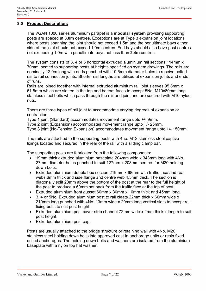
3.0 Product Description:
ing supporting joint locations
and the penultimate bays either side of the joint should not exceed 1.0m centres. End bays should also have post centres
tions 114mm x m located to supporting posts at heights specified on system drawings. The rails are
s to receive bolted joints and ends
Rails are joined together with internal extruded aluminium rail joint sleeves 95.8mm x o. M10x80mm long
and are secured with M10 nyloc
There are three types of rail joint to accommodate varying degrees of expansion or
pto +/- 9mm. nge upto +/- 25mm.
e upto +/- 150mm.
ts with 4no. M12 stainless steel captive bar.
m long with 4No. s for M20 holding
face and rear mm thick and side flange and centre web 4.5mm thick. The section is
above the bottom of the post at the rear to the full height of the post to produce a 60mm set back from the traffic face at the top of post.
nd 45mm long. mm wide x
4No. 13mm wide x 20mm long vertical slots to accept rail fixing bolts to suit post height.
Extruded aluminium post cover strip channel 72mm wide x 2mm thick x length to suit post height.
Extruded aluminium post cap.
Posts are usually attached to the bridge structure or retaining wall with 4No. M20 stainless steel holding down bolts into approved cast-in anchorage units or resin fixed drilled anchorages. The holding down bolts and washers are isolated from the aluminium baseplate with a nylon top hat washer.
The VGAN 1000 series aluminium parapet is a modular system providposts are spaced at 3.0m centres. Exceptions are at Type 3 expansion where posts spanning the joint should not exceed 1.5m
not exceeding 1.0m with penultimate bays not less than 2.4m centres. The system consists of 3, 4 or 5 horizontal extruded aluminium rail sec70mnominally 12.0m long with ends punched with 10.5mm diameter holerail to rail connection joints. Shorter rail lengths are utilised at expansionof runs.
61.5mm which are slotted in the top and bottom faces to accept 5Nstainless steel bolts which pass through the rail and joint nuts.
contraction. Type 1 joint (Standard) accommodates movement range uType 2 joint (Expansion) accommodates movement raType 3 joint (No-Tension Expansion) accommodates movement rang
The rails are attached to the supporting posfixings located and secured in the rear of the rail with a sliding clamp
The supporting posts are fabricated from the following components: 19mm thick extruded aluminium baseplate 204mm wide x 343m
27mm diameter holes punched to suit 127mm x 203mm centredown bolts.
Extruded aluminium double box section 219mm x 68mm with trafficwebs 6diagonally split 20mm
Extruded aluminium front gusset 60mm x 30mm x 10mm thick a 3, 4 or 5No. Extruded aluminium post to rail cleats 22mm thick x 66
210mm long punched with

VGAN 1000 Specification Manual Complied By: D.V.Copeland November 2012 - Issue 1 Revision 0
Varley and Gulliver Limited. Page 8 of 22 VGAN 1000
4.0 Durability:
ors such as weather ce.
pervious oxide layer ly resistant to
pid forming of the oxide layer and reforming of the layer of aluminium and
ited life expectancy.
etallic corrosion
ntact with each other in asses of the two
hich would be the pared with the nt of isolation
less steel fixings in aluminium components, in our opinion, is over specified and the use of stainless steel in contact with aluminium in several existing parapet
seplate which lon isolation
visible spots on the ason Aluminium te is painted with
s of bitumastic paint to prevent alkaline contact during the grouting process. After
tact with a humid environment. In general, the consequence is only aesthetical.
ility due to the during routine
Agency on the e listed below
“If the Skin is broken by actions such as scraping, a new oxide layer will form on the
exposed aluminium so it is considered to be self healing.” “Aluminium Alloys are highly resistant to corrosion. For this reason they are often
used in marine structures such as navigation buoys, life boats and general shipping.” “It is the experience of military equipment that any aluminium alloy surface which is
free draining and exposed to the full force of the weather will not corrode and will not noticeably deteriorate over very long periods. The military experience covers 20 to 30 years and if this is extrapolated it shows that the 120 year life of a civil bridge is
The durability of a product is dependent upon numerous factconditions, air pollution, location, handling, repair and routine maintenan Aluminium weathers to a dull grey finish due to the formation of an imwhich is integral with the base metal on exposed surfaces, which is highatmospheric corrosion. The rawhen scratched is a main reason for the good corrosion characteristicsan almost unlim The use of stainless steel fixings in aluminium can raise concern of bi-m(Galvanic corrosion). Galvanic corrosion takes place when two different metals have cothe presence of an electrolyte and is also dependent upon the relative mmaterials and the level of current density in the sacrificial anode waluminium extrusions. The high relative mass of the aluminium comstainless steel fixings would result in a low current density. The extebetween stain
systems used for over 30 years in the UK would verify. The main area of concern would be the holding down bolts and the bawould be prone to standing water and road salts and for this reason a nywasher is utilised. Splashes of alkaline building materials like grout and concrete causesurface of the Aluminium. These are difficult to remove and for this reshould be protected on site. The underside of the Aluminium baseplatwo coatthe cementation of the grout corrosion cannot happen. Pitting corrosion can occur on aluminium surfaces frequently in con
Accumulation of dirt and debris on surfaces can cause a reduced durabonsequence of long-term moisture. Dirt and debrisc should be removed
inspections.
In 1998 Mouchel Consulting Limited produced a report for The Highway Opportunities for Use of Aluminium in Highway Structures, and we havseveral relevant extracts regarding durability from this report.

VGAN 1000 Specification Manual Complied By: D.V.Copeland November 2012 - Issue 1 Revision 0
Varley and Gulliver Limited. Page 9 of 22 VGAN 1000
ability and the
ed in a marine not have a
d by the experience tures in extremely
equences than n initiate unsightly
.” “Reduced maintenance can be confidently anticipated as a consequence of the use
ay costs.”
environment.
icularly applicable to ater effect when
uch longer design life dition, the traffic
cation.” ontent when
recycled. The highway network must not be burdened with a rate of replacement and traffic.”
mental and ntly can be easily
riginal energy consumption. Reduced need for
e depth of weathering of a 0.91mm aluminium sheet exposed for 20 years in a tropical, industrial and marine environment resulted in a loss of thickness of 0.02mm, 0.05mm and 0.08mm respectively with 85% of reduction occurring within the first 3 years of exposure.
Therefore to specify exact working life duration is virtually impossible but based on the above would predict durability in accordance with the requirements of Manual of Contract Documents for Highway Works Volume 1 for parapets of 60 years or more dependent upon routine inspection, repair and maintenance.
easily met, and the infinite life predicted by some manufacturers is only a modest exaggeration.”
“The greatest long term advantage of aluminium alloys is their durconsequent reduction in maintenance costs.”
“Aluminium alloys will suffer from pitting corrosion and this is increasenvironment. However the rate of such pitting is so slow that it willsignificant effect on the life of structural sections. This is supporteof a long life of structures in ships, buoys, and other marine strucaggressive environments.”
“Aluminium alloys without coatings are less susceptible to the conspainted steel structures, where local damage by vandals cabreakdown of the protective system and subsequent corrosion
of aluminium alloy, with a significant reduction in access and del
For additional information we have also listed extracts regarding the
”The environmental advantages of aluminium alloys are partstructural applications. The reduction in maintenance will have a greapplied to long life structures, and highway bridges have a mthan building or the more usual applications for the material. In addelay cost savings are a particularly significant factor in this appli
“Materials themselves must be sustainable, and of low energy c
maintenance in the future that imposes unacceptable delays on “There is very strong case to make for aluminium alloy on environ
sustainability grounds. The material is plentiful, but more importarecycled using only 5% of its omaintenance also has significant environmental and sustainability advantages.”
Based on an EAA report on the averag
VGAN 1000 Specification Manual Complied By: D.V.Copeland November 2012 - Issue 1 Revision 0
Varley and Gulliver Limited. Page 10 of 22 VGAN 1000
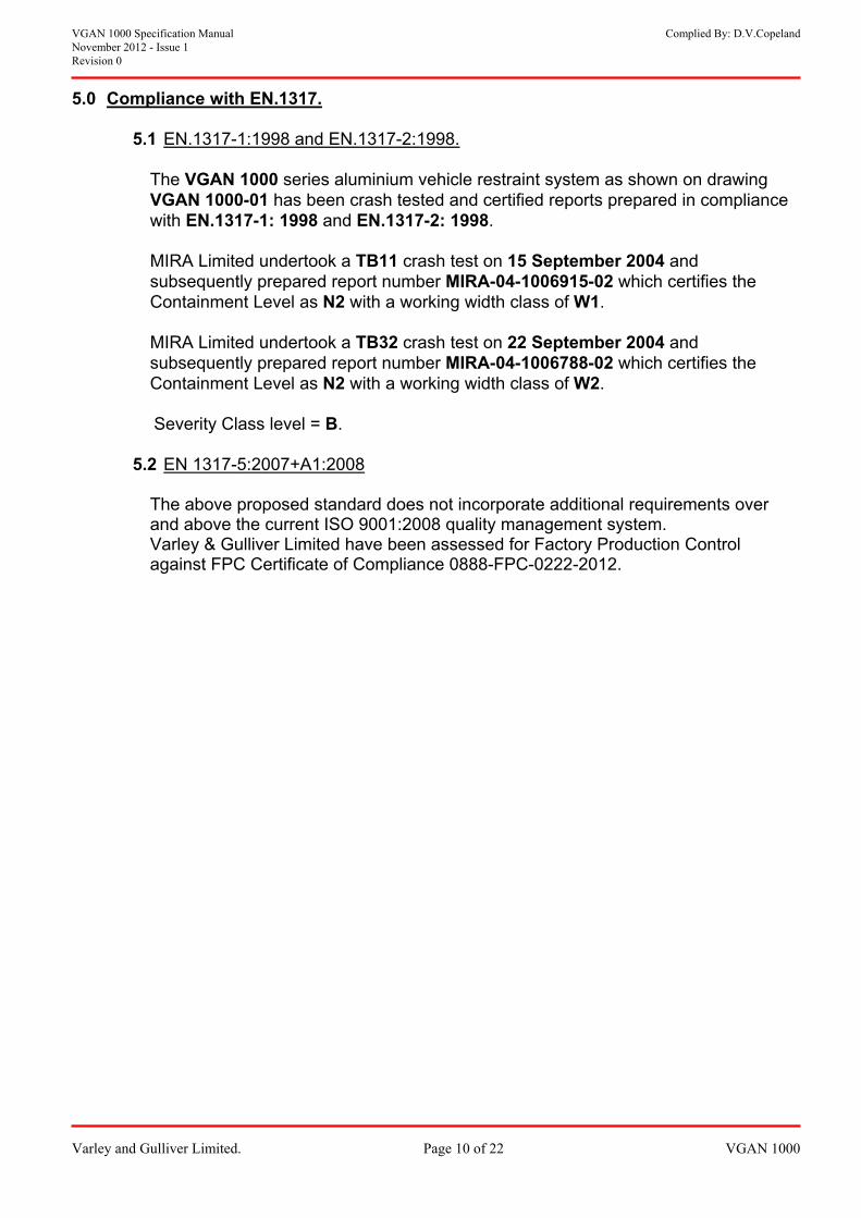
5.0 Compliance with EN.1317.
5.1 EN.1317-1:1998 and EN.1317-2:1998.
The VGAN 1000 series aluminium
vehicle restraint system as shown on drawing VGAN 1000-01 has been crash tested and certified reports prepared in compliance
TB11 15 September 2004 and
-02 which certifies the
took a TB32 crash test on 22 September 2004 and
subsequently prepared report number MIRA-04-1006788-02 which certifies the N2 with a working width class of W2.
with EN.1317-1: 1998 and EN.1317-2: 1998.
MIRA Limited undertook a crash test on subsequently prepared report number MIRA-04-1006915Containment Level as N2 with a working width class of W1.
MIRA Limited under
Containment Level as
Severity Class level = B.
5.2 EN 1317-5:2007+A1:2008 The above proposed standard does not incorporate additional requirements over and above the current ISO 9001:2008 quality management system. Varley & Gulliver Limited have been assessed for Factory Production Control against FPC Certificate of Compliance 0888-FPC-0222-2012.
VGAN 1000 Specification Manual Complied By: D.V.Copeland November 2012 - Issue 1 Revision 0
Varley and Gulliver Limited. Page 11 of 22 VGAN 1000
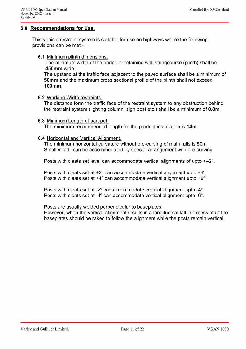
6.0 Recommendations for Use.
int system is suitable for use on highways where the following
plinth dimensions.
This vehicle restraprovisions can be met:-
6.1 Minimum inth) shall be
to the paved surface shall be a minimum of imum cross sectional profile of the plinth shall not exceed
ints.
The minimum width of the bridge or retaining wall stringcourse (pl450mm wide. The upstand at the traffic face adjacent 50mm and the max100mm.
6.2 Working Width restra to any obstruction behind
the restraint system (lighting column, sign post etc.) shall be a minimum of 0.8m. The distance form the traffic face of the restraint system
6.3 Minimum Length of parapet.
he minimum recommended length for the product installatio T n is 14m.
6.4 Horizontal and Vertical Alignment.
ain rails is 50m.
ments of upto +/-2º.
to +4º. pto +6º.
The minimum horizontal curvature without pre-curving of mSmaller radii can be accommodated by special arrangement with pre-curving.
Posts with cleats set level can accommodate vertical align Posts with cleats set at +2º can accommodate vertical alignment up
Posts with cleats set at +4º can accommodate vertical alignment u Posts with cleats set at -2º can accommodate vertical alignment upto -4º.
Posts with cleats set at -4º can accommodate vertical alignment upto -6º.
Posts are usually welded perpendicular to baseplates. However, when the vertical alignment results in a longitudinal fall in excess of 5° the
baseplates should be raked to follow the alignment while the posts remain vertical.
VGAN 1000 Specification Manual Complied By: D.V.Copeland November 2012 - Issue 1 Revision 0
Varley and Gulliver Limited. Page 12 of 22 VGAN 1000
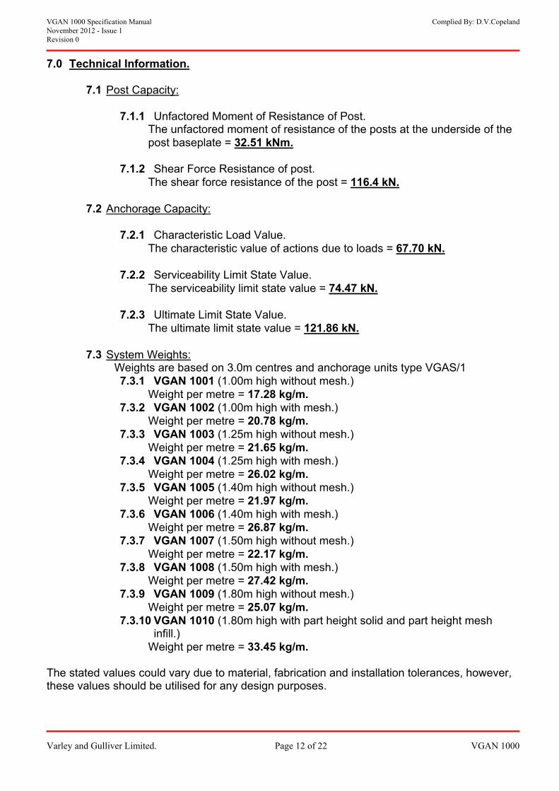
7.0 Technical Information.
7.1 Post Capacity:
7.1.1 Unfactored Moment of Resistance of Post. The unfactored moment of resistance of the posts at the underside of the post baseplate = 32.51 kNm.
r Force Resistance of post.
The shear force resistance of the post = 116.4 kN.7.1.2 Shea
7.2 Anchorage Capacity:
7.2.1 Characteristic Load Value. The characteristic value of actions due to loads = 67.70 kN.
e.
e serviceability limit state value = 74.47 kN.7.2.2 Serviceability Limit State Valu
Th
e = 121.86 kN.7.2.3 Ultimate Limit State Value.
The ultimate limit state valu
7.3 System Weights: Weights are based on 3.0m centres and anchorage units type VGAS/1
ithout mesh.) m. h mesh.)
g/m. igh without mesh.)
m. ith mesh.)
g/m. out mesh.)
.97 kg/m.
.87 kg/m. 7.3.7 VGAN
with mesh.) Weight per metre = 27.42 kg/m.
7.3.9 VGAN 1009 (1.80m high without mesh.) Weight per metre = 25.07 kg/m.
7.3.10 VGAN 1010 (1.80m high with part height solid and part height mesh infill.)
Weight per metre = 33.45 kg/m. The stated values could vary due to material, fabrication and installation tolerances, however, these values should be utilised for any design purposes.
7.3.1 VGAN 1001 (1.00m high wWeight per metre = 17.28 kg/
7.3.2 VGAN igh wit1002 (1.00m h Weight per metre = 20.78 k7.3.3 VGAN 1003 (1.25m h
Weight per metre = 21.65 kg/7.3.4 VGAN 1004 (1.25m high w
.02 kWeight per metre = 267.3.5 VGAN 1005 (1.40m high with
Weight per metre = 217.3.6 VGAN 1006 (1.40m high with mesh.)
Weight per metre = 261007 (1.50m high without mesh.)
Weight per metre = 22.17 kg/m. 7.3.8 VGAN 1008 (1.50m high

VGAN 1000 Specification Manual Complied By: D.V.Copeland November 2012 - Issue 1 Revision 0
Varley and Gulliver Limited. Page 13 of 22 VGAN 1000
8.0 Certification.
8.1 BS.EN.ISO 9001:2008 Quality Management Certificate.

VGAN 1000 Specification Manual Complied By: D.V.Copeland November 2012 - Issue 1
ion 0
Varley and Gulliver Limited. Page 14 of 22 VGAN 1000
Revis
9.0 Approved Anchorage Units.
9.1 VGAS/1 Anchorage unit.
9.1.1 Drawing Number VGAS/1.
9.2 VGAS/2 Anchorage unit.
9.2.1 Drawing Number VGAS/2.
9.3 VGAS/3 Anchorage Unit.
r VGAS/3.
9.4 SSR 120-VDI-CM25 Anchor.
9.3.1 Drawing Numbe
9.4.1 Drawing Number 231/2.

VGAN 1000 Specification Manual Complied By: D.V.Copeland November 2012 - Issue 1 Revision 0
Varley and Gulliver Limited. Page 15 of 22 VGAN 1000
SECTION ‘B’ – INSTALLATION MANUAL.

VGAN 1000 Specification Manual Complied By: D.V.Copeland November 2012 - Issue 1 Revision 0
Varley and Gulliver Limited. Page 16 of 22 VGAN 1000
1. Scope:
passes the work involved to erect VGAN 1000 Series Aluminium Vehicle / Pedestrian parapet.
1.1 This Method Statement encom

VGAN 1000 Specification Manual Complied By: D.V.Copeland November 2012 - Issue 1 Revision 0
Varley and Gulliver Limited. Page 17 of 22 VGAN 1000
2.0 Safety:
ng:
rk Act.
d Statement(s) & Risk
Assessment(s).
ulliver Limited Site operatives will be experienced tradesmen. The nominated Contract Manager and Installation Supervisor will ensure safe working
uring the duration lliver Limited
s as specified by Varley & and certified in the
Visibility clothing, Hard Hats will be worn as a matter of course.
Assessments prior to commencement of work.
.6 Clear vehicular access must be provided for our lorries to load/unload and for our vans whilst work is ongoing.
2.7 No other trades to have access to work areas whilst Varley & Gulliver’s operations
are ongoing unless otherwise agreed.
2.1 All work will comply with the followi
2.1.1 The Health and Safety at Wo
2.1.2 Varley and Gulliver’s Safety Handbook.
2.1.3 Varley and Gulliver associated Metho
2.1.4 Any Site Inductions given by the Main Contractor.
2.2 All Varley & G
practices are adhered to by Varley & Gulliver Limited employees dof on site work. Any other matters are to be directed to Varley & GuContracts Division.
2.3 All operatives will comply with Site Safety Procedure
Gulliver & the Main Contractor. All Plant operators will be trainedsafe operation and use of the equipment they are utilising.
2.4 All personnel will wear the correct PPE for the task in hand. High
Safety Footwear and
2.5 All personnel will be given a copy of this Method Statement and associated Risk
2

VGAN 1000 Specification Manual Complied By: D.V.Copeland November 2012 - Issue 1 Revision 0
Varley and Gulliver Limited. Page 18 of 22 VGAN 1000
3.0 Sequence of Operations:
3.1 Installation of Posts and Rails:
.
ter along the
3.1.4 the M20 stainless steel holding down
ired. Place g down bolts to ensure that the plastic top hat washer is in
applied (copper
3.1.7 Locate post over anchor cluster and insert the M20 bolts with washers through
.
nd by rocking front age, bolts should be
3.1.10 referably the left) begin erecting the the structure.
d slide along the ck of the rails. The quantity of clamp bars required is dependant upon the
3.1.11 Offer the rails up into position (starting with the bottom rail) and fit the
3.1.12 Once the first set of rails are installed, plumb the end of the rails and tighten
post/rail bolts. Do not apply the required torque to the post/rail bolts at this stage.
3.1.13 Determine from the GA layout drawing if safety fence connectors are to be
installed at the ends of the rails and proceed to fit (if required). 3.1.14 Insert the rail to rail joints pieces and fix with M10x80 long stainless steel
bolts, M10 nyloc nuts and washer bars.
3.1.1 No work will commence until items 2.6 & 2.7 have been met
3.1.2 Identify positions from the General Arrangement (GA) drawings and place all posts and rails in the required locations.
3.1.3 Place solid inert packer(s) in the centre of the anchor clusstringcourse.
Layout in front of each post location bolts c/w stainless steel washers and plastic top hats as requwashers onto holdincontact with the baseplate upon installation.
3.1.5 Ensure that the threads of all bolts have a thin coat of grease
slip or similar) prior to fitting.
3.1.6 Check that anchorage sockets are clean and free of debris.
the baseplate into the anchorage sockets
3.1.8 Plumb posts in both elevations using the central packer, ato side. Do not apply final torque to the M20 bolts at this sttightened no more than finger tight at this stage.
3.1.9 Repeat items 3.1.3 – 3.1.8 along length of work area.
Starting at one end of the structure (prails by laying them on battens/packers, to avoid damage, onInsert the M12 Stainless Steel bolts into the clamp bars anbanumber of posts the rail is fixed too.
post/rail fixings.

VGAN 1000 Specification Manual Complied By: D.V.Copeland November 2012 - Issue 1 Revision 0
Varley and Gulliver Limited. Page 19 of 22 VGAN 1000
3 g entire length of the work aps are set (see GA drawing).
nment.
.1.15 Repeat steps 3.1.11 – 3.1.13 and step 3.1.15 alon
area, ensuring the correct rail joint g 3.1.16 Repeat step 3.14 at the other end (if required).
3.1.17 Line and level by means of eying in the top rail, lifting and lowering posts using thin shims for level and using rocking action for alig
3.1.18 Check and tighten down all holding down bolts (still no mortight), apply the correct torque of 80Nm to the pos
e than finger t / rail bolts.
3.1.19
minimum of 25mm. When parapets are attached to anchorage provided by other the following
followed:
When parapets are attached to Varley and Gulliver Limited anchorage units the length of bolt engagement needs to be a
equation should be LE = 0.7 x Ultimate Tensile Strength of Fixings x D
ength of Engagement
eter.
ets to be completed epresentative from the client for approval and
3.2 Grouting under Baseplates:
0.2% Proof Stress of Anchorage Socket Where: LE = L
D = Bolt Diam 3.1.20 Line and Level to be passed off and Job Instruction She
and passed to the relevant rsignature.
ly to fall to
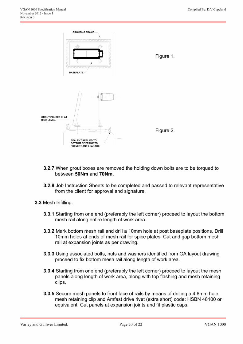
3.2.2 Using 2” x 1” wood, construct a grouting frame slightly bigger than the
sealant (where appropriate) to the outside of the frame when positioning, to stop any grout from seeping out.
3.2.4 Place the frame around the baseplate and pour in an approved non-shrink
grout at the high end (See Figure 2.) Ensure that the grout runs through to all sides.
3.2.5 Leave the grout to set. (as per manufacturers’ recommendations). 3.2.6 Once set remove the frame.
3.2.1 If the temperature is likely to fall below 5 degrees Centigrade for 24 hours
either side of pouring the grout either:
a) Cover area with hessian, providing temperature is not likefreezing point. b) DO NOT grout.
baseplate. (See Figure 1.) 3.2.3 Nail the frame together and apply silicone
VGAN 1000 Specification Manual Complied By: D.V.Copeland November 2012 - Issue 1 Revision 0
Varley and Gulliver Limited. Page 20 of 22 VGAN 1000
GROUT POURED IN AT HIGH LEVEL.
SEALENT APPLIED TO BOTTOM OF FRAME TPREVENT ANY LEAKA
O GE.
GROUTING FRAME.
BASEPLATE.
Figure 1.
Figure 2.
en grout boxes are removed the holding down bolts are to be torqued to
3.2.8 Job Instruction Sheets to be completed and passed to relevant representative
3 Mesh Infilling:
3.2.7 Whbetween 50Nm and 70Nm.
from the client for approval and signature.
3.
.3.1 Starting from one end (preferably the left co3 rner) proceed to layout the bottom
3 late positions. Drill 10mm holes at ends of mesh rail for spice plates. Cut and gap bottom mesh
3.3.3
proceed to fix bottom mesh rail along length of work area. 3.3.4 Starting from one end (preferably the left corner) proceed to layout the mesh
panels along length of work area, along with top flashing and mesh retaining clips.
3.3.5 Secure mesh panels to front face of rails by means of drilling a 4.8mm hole,
mesh retaining clip and Amfast drive rivet (extra short) code: HSBN 48100 or equivalent. Cut panels at expansion joints and fit plastic caps.
mesh rail along entire length of work area.
.3.2 Mark bottom mesh rail and drill a 10mm hole at post basep
rail at expansion joints as per drawing.
Using associated bolts, nuts and washers identified from GA layout drawing

VGAN 1000 Specification Manual Complied By: D.V.Copeland November 2012 - Issue 1 Revision 0
Varley and Gulliver Limited. Page 21 of 22 VGAN 1000
3.3.6 Proceed along entire length of work area repeating step 3.3.5.
3 nt locations. 4.8mm holes at
centres not exceeding 203mm, fixed with Amfast drive rivets (extra long) code: ll rail joint locations.
ts using a soft
Job Instruction Sheets to be completed and passed to relevant representative from
the client for approval and signature.
.3.7 Fix vertical end flashings at ends of runs and at expansion joi
Proceed to fix top flashing to top rail along entire run, drilling
HSBN 48180 or equivalent. Top flashing to stop / start at a
3.3.8 After steps 3.3.2 – 3.3.7 remove all swarf from rails and poshand brush. Collect up all off cuts and dispose of off site.

VGAN 1000 Specification Manual Complied By: D.V.Copeland November 2012 - Issue 1 Revision 0
Varley and Gulliver Limited. Page 22 of 22 VGAN 1000
4.0 Routine Inspections:
aluminium parapet is carried and principle inspections of the main structure.
4
4.1 It is recommended that a general inspection of the
out during routine
.2 Guidance for Inspection:
s part of the inspection:
Absence of or damage to grout pad. p of debris and dirt.
(where applicable.)
4.3
The following items should be reviewed a
Absence or looseness of bolts or nuts.
Build u Adequate attachment of mesh infill.
Accident Damage Inspection:
aThe following items should be reviewed s part of the inspection:
cular attention to be paid to the post to baseplate weld and post to cleat welds.
Absence of or damage to grout pad. Build up of debris and dirt. Adequate attachment of mesh infill. (where applicable.)
If in any doubt contact Varley and Gulliver Limited who can offer advice or arrange a site visit.
Any cracks in or adjacent to welds. Parti
Absence or looseness of bolts or nuts.