Embed Size (px)
Citation preview

Model 58300/300SW/New/May 2015 Page 1 Altronic Research Inc.
ALTRONIC RESEARCH, INC. P.O. BOX 249, YELLVILLE, ARKANSAS, U.S.A. 72687-0249
PHONE 870-449-4093 FAX 870-449-6000
1-800-482-LOAD (5623) in US
www.altronic.com
MODEL 58300 / 300 SW INTEGRATED COAXIAL LOAD
SYSTEM

Model 58300/300SW/New/May 2015 Page 2 Altronic Research Inc.
MODEL 58300 / 300 SW INTEGRATED COAXIAL LOAD
SYSTEM

Model 58300/300SW/New/May 2015 Page 3 Altronic Research Inc.
LIMITED WARRANTY We take pride in manufacturing products of the highest quality and we warrant them to the original purchaser to be free from defects in material and workmanship for the period of one year from date of invoice. Additionally, products of our manufacture repaired by us are warranted against defects in material and workmanship for a period of 90 days from date of invoice, with the provisions described herein. Should a product, or a portion of a product of our manufacture prove faulty, in material or workmanship, during the life of this warranty, we hereby obligate ourselves, at our own discretion, to repair or replace such portions of the product as required to remedy such defect. If, in our judgment, such repair or replacement fails to be a satisfactory solution, our limit of obligation shall be no more than full refund of the purchase price. This warranty is limited to products of our own manufacture. Equipment and components originating from other manufacturers are warranted only to the limits of that manufacturer's warranty to us. Furthermore, we shall not be liable for any injury, loss or damage, direct or consequential, arising out of the use, or misuse (by operation above rated capacities, repairs not made by us, or any misapplication) of the equipment. Before using, the user shall determine the suitability of the product for the intended use; and the user assumes all risk and liability whatsoever in connection therewith. The foregoing is the only warranty of Altronic Research Incorporated and is in lieu of all other warranties expressed or implied. Warranty returns shall first be authorized by the Customer Service Department and shall be shipped prepaid. Warranty does not cover freight charges.
Model 58300/300SW/New/May 2015 Page 4 Altronic Research Inc.
TABLE OF CONTENTS MODEL 58300 / 300 SW
SECTION PAGE
Warranty ............................................................................................................. 3 Precautions ....................................................................................................... 7,8 Introduction ......................................................................................................... 9 I. Description and Leading Particulars 1.1 Purpose and Application of Equipment ........................................ 9 1.2 Equipment Supplied ...................................................................... 9 1.3 Equipment Required But Not Supplied ........................................ 9 1.4 General Description ...................................................................... 9 1.5 Performance Characteristics ....................................................... 10 1.6 Test Equipment Required ........................................................... 10 1.7 Special Tools Required ............................................................... 10 II. General Theory of Operation 2.1 – 2.4.............................................................................................. 11 III. Dry Cooler Installation
3.1 Inspection.............................................................................................. 12 3.2 Unpacking ............................................................................................. 12 3.3 Site Plan ................................................................................................ 12 3.4 Installation ............................................................................................ 12 3.5 Electrical Installation ............................................................................ 12 3.6 Dry Cooler Electrical ............................................................................ 13 3.7 Fan Control Cabling ............................................................................. 13 3.8 Dry Cooler Fan Rotation Verification .................................................. 13 3.9 Plumbing Installation ............................................................................ 14 3.10 Flange Connection ............................................................................... 14
IV. Main Frame Installation 4.1 Inspection.............................................................................................. 15 4.2 Unpacking ............................................................................................. 15 4.3 Installation ............................................................................................ 15 4.4 Electrical Safety and Lockout Procedures ............................................ 15 4.5 Connect AC Mains ............................................................................... 16 4.6 Connect Transmitter Interlock .............................................................. 16 4.7 Connect Dry Cooler Control Cabling ................................................... 16 4.8 Connect Dry Cooler Plumbing ............................................................. 16 4.9 Connect RF Line to Main Frame .......................................................... 16

Model 58300/300SW/New/May 2015 Page 5 Altronic Research Inc.
SECTION PAGE V. Initial Integrated Coaxial Load System Start-up 5.1 Main Frame Coaxial Load Start-up ............................................ 17 5.2 Pump Priming Procedure ............................................................ 17 5.3 System Start-up ........................................................................... 18 5.4 Calibrate Power ........................................................................... 18 VI. Operating Instructions 6.1 Operation .................................................................................... 19 6.2 Post-Operation ............................................................................ 19 VII. Calorimetry 7.1 General ........................................................................................ 20 7.2 Calorimetry Theory ..................................................................... 20 7.3 Practical Calorimetry .................................................................. 20 Kt Graph.................................................................................... 21 Coolant Density/Flow Meter Correction .................................. 22 Ethylene Glycol Solution Densities .......................................... 23 VIII. Program Instructions ......................................................................... 24-36 IX. Maintenance 9.1 157200SB Loads ......................................................................... 37 9.2 Calorimetry System .................................................................... 37 9.3 Coolant System ........................................................................... 37 9.4 Dry Cooler ................................................................................. 38 9.5 Cleaning and Lubrication ............................................................ 38 X. Storage 10.1 The Main Frame ........................................................................ 39 10.2 The Drycooler ........................................................................... 39 Schematic Diagram ........................................................................................... 40 Specifications .................................................................................................... 42

Model 58300/300SW/New/May 2015 Page 6 Altronic Research Inc.
Appendix A Coolant Specifications .............................................................. 43

Model 58300/300SW/New/May 2015 Page 7 Altronic Research Inc.
PRECAUTIONS
DANGER Do not attempt any service or parts replacement without first disconnecting all AC power and RF power. Failure to do so may result in serious or fatal electrical shock.
!!!WARNING!!! Before operating equipment insure interlock is operating properly. Not doing so can result in a dangerous, possibly lethal condition. Application of RF even momentarily if unit is off or coolant flow is restricted will result in damage to equipment. Operating without interlock will void the warranty. Do not apply more than rated power to unit. Damage will occur before thermal protectors can activate interlock circuit if more than rated power is applied.
WARNING Ethylene Glycol may cause permanent damage to the kidneys, liver and other organs if ingested. Avoid excessive contact with skin or eyes. See the Material Safety Data Sheet for the specific precautions and first aid measures prescribed by the manufacturer.
CAUTION Remove snow and any debris from top surface and from below dry cooler before operation. Restrictions in airflow limit the dry cooler’s ability to dissipate RF power and could damage and/or cause the unit to fail.
CAUTION Do not operate with coolant low or empty. To do so will result in damage to working parts and seals.
Model 58300/300SW/New/May 2015 Page 8 Altronic Research Inc.
PRECAUTIONS
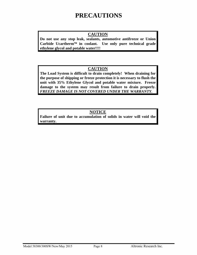
CAUTION Do not use any stop leak, sealants, automotive antifreeze or Union Carbide Ucartherm™ in coolant. Use only pure technical grade ethylene glycol and potable water!!!!
CAUTION The Load System is difficult to drain completely! When draining for the purpose of shipping or freeze protection it is necessary to flush the unit with 35% Ethylene Glycol and potable water mixture. Freeze damage to the system may result from failure to drain properly. FREEZE DAMAGE IS NOT COVERED UNDER THE WARRANTY.
NOTICE Failure of unit due to accumulation of solids in water will void the warranty.

Model 58300/300SW/New/May 2015 Page 9 Altronic Research Inc.
INTRODUCTION
This handbook is for technical personnel as an aid in understanding and performing installation, service and maintenance procedures for the OMEGALINE® Model 58300 / 300 SW Integrated Coaxial Load System Load. Personnel are considered to be skilled if they have the necessary knowledge and practical experience of electrical and radio engineering to appreciate the various hazards that can arise from working on radio transmitters, and to take appropriate precautions to ensure the safety of personnel.
SECTION I
DESCRIPTION AND LEADING PARTICULARS
1.1. Purpose and Application of Equipment. The OMEGALINE® Model 58300 / 300 SW Integrated Coaxial Load System is designed to continuously dissipate 300,000 watts of RF power when operated within its specified ambient temperature range.
1.2. Equipment Supplied. One Main Frame, Dummy Load, Model 58300 / 300 SW One Dry Cooler, COLMAC Model AFV-45162-10.533L-C-G-30-1-BT-D 1.3. Equipment Required But Not Supplied. Piping from the Main Frame to the Dry Cooler and return. Wiring from the Main Frame (Control Box) to the Dry Cooler for control. Inhibited ethylene glycol for glycol solution (if used) (See Appendix A for specifications.) 1.4. General Description. This device is composed of four major groups of equipment: (1) the
load elements; (2) the pump and control circuitry; (3) the dry cooler; and (4) the calorimetry system.
The load elements are RF dummy loads nominally rated at 150kW each. They are
mounted on a steel frame with the pumps, valves, sensors and switches, and control box. The control box contains the calorimetry PLC. This unit is designated the Main Frame and is designed for outdoor installation with remote control panel. It must not be subjected to freezing temperatures without special preparation. (See storage instructions.)
The Dry Cooler is composed of one coil assembly which is mounted horizontally in a
galvanized steel frame. The coil is cooled by three fans. The fans are mounted below the coils and draw air through the coils, exhausting it upwards. Control circuitry for the Dry Cooler is contained in an integral compartment in the enclosure with a remote control panel. The Dry Cooler is designed for outdoor installation. See Section III.
The load elements are cooled by water which is pumped and circulated through the loads
and the dry cooler. Heat is removed from the coolant solution (a 5-10% inhibited ethylene

Model 58300/300SW/New/May 2015 Page 10 Altronic Research Inc.
glycol and water solution (glycol solution) by the dry cooler or as recommended by COLMAC).
1.5. Performance Characteristics. When properly serviced, this device is very reliable and
capable of continuous operation at 300kW RMS input. The Main Frame requires protection from freezing unless prepared for storage. It is designed for installation in exposed locations, but should not be subjected to snow loads falling from nearby buildings. It is not guaranteed to function properly if snow is allowed to accumulate around and beneath the unit.
1.6. Test Equipment Required. No test equipment is required for routine maintenance,
however it may be necessary to verify DC resistance of the coaxial resistor and/or verify coolant temperature, in which case you will need an accurate digital ohmmeter and precision thermometer.
1.7. Special Tools Required. This device is easily maintained with common hand tools and
general electronic servicing tools. Many faults can be corrected in less than one hour. Common hand tools will be adequate for most maintenance. In addition, 24 inch pipe wrenches should be available.

Model 58300/300SW/New/May 2015 Page 11 Altronic Research Inc.
SECTION II
GENERAL THEORY OF OPERATION 2.1. The Model 58300 / 300 SW is an energy conversion and transfer device. RF energy is
conducted to the loads by the RF duct, where it enters the two 150Ω balanced loads through stud connections. Each load is nominally rated at 150kW. The RF energy is converted to heat by the resistive elements in the loads.
CARE SHOULD BE TAKEN TO OPERATE UNIT BELOW STATED MAXIMUM
AMBIENT OPERATING TEMPERATURE.
OPERATION ABOVE RATED AMBIENT TEMPERATURE 40°C STANDARD MAY CAUSE MOTOR THERMAL
PROTECTION TO SHUT OFF FANS, WHICH MAY CAUSE DAMAGE TO UNIT.
PROVISIONS ARE MADE TO TRIP THE INTERLOCK IN THE EVENT OF
OVERHEAT, BUT THE INTERLOCK MUST BE PROPERLY CONNECTED TO THE RF SOURCE FOR THIS FUNCTION TO OPERATE.
NEVER OPERATE WITH INTERLOCK DISCONNECTED
OR MALFUNCTIONING. 2.2. Each load is made with a single resistor and is water-cooled. Cooling water enters the
load at the bottom (opposite the RF end) and flows through the center of the resistor to the RF end where it turns and enters the space between the outside of the resistor and the inside of the water jacket. This water is in direct contact with the resistive film and absorbs the heat produced by the resistor as it flows to the bottom of the load. The water then enters an annular chamber and is discharged from the side of the water housing cap. Upon leaving the load, the coolant stream passes through the dry cooler before returning to the loads.
2.3. There is a 3 HP pump on the main frame. The cooling water pump is stainless steel and
is designed to flow approx. 50 GPM. The pump is controlled by a switch on the control panel of the system.
2.4. The Control Panel contains all of the electrical and electronic components necessary for
starting and operating the pump and sensing the operating conditions of the loads. The control circuitry is designed to provide an interlock signal to the RF source to prevent the application of power to the load when it is not ready to dissipate heat. The logic of the system is simple and depends on the closure of a series of switches and relays in order to enable the transmitter. When power is applied and no fault conditions exist, the transmitter interlock is enabled.

Model 58300/300SW/New/May 2015 Page 12 Altronic Research Inc.
SECTION III
DRY COOLER INSTALLATION 3.1. Inspection Prior to Unpacking. Inspect outer carton for evidence of damage during
shipment. We suggest that the user collect and preserve all documentation such as Bills of Lading, Manifests, etc. Claims for damage in shipment must be filed promptly with the transportation company involved. Altronic Research Inc. is not responsible for damage incurred in transportation.
3.2. Unpacking. Remove crating. The cooler and leg assemblies are mounted to the
shipping platform with lag bolts. All of these bolts must be removed. Retain shipping materials if unit is to be reshipped.
3.3. Site Plan. The engineering site plan is developed by the group responsible for RF,
electrical, mechanical, and layout of the project. The final plan for this installation must be developed on-site and is beyond the scope of this manual. See Attachment B: Dry Cooler Drawings.
3.4. Installation. The configuration of the Dry Cooler may be varied. The smaller systems
may be shipped complete, while the larger units may require some assembly. All loads have an expansion tank that may or may not require installation. The support legs may have to be installed on the larger dry coolers. The manufacturer of the Dry Cooler has prepared detailed plans for its assembly and installation. They are included in this manual as Attachments A and B. Be certain that these instructions are read and understood before beginning the installation work. The basic steps are summarized below: 1. Prepare footing for placement. 2. Lift cooler coil assembly and install mounting legs (on some units). 3. Position Dry Cooler in installation spot and securely bolt it in place. 4. Install expansion tank if not installed prior to shipment. The Site Installation
Coordinator provides pipe fittings.
3.5. Electrical Installation. Electrical safety and lockout procedures: 1. Turn off main power source to applicable system. 2. Lock out applicable breaker. 3. Tag and flag locked out breaker. 4. Comply with all electrical safety procedures and practices as required by site safety
plan.
Special Equipment Required: Crane–Adequate capacity with lifting slings.
Attachment A – Installation, Operation and Maintenance (Section 4.2) contains detailed sling, spreader bar and lifting instructions. Personnel who are to perform the task of lifting the unit should read and follow these directions to avoid damage to the coil assembly.

Model 58300/300SW/New/May 2015 Page 13 Altronic Research Inc.
AIR FLOW
5. Verify that power has been removed from the applicable unit using voltmeter at the AC Mains terminals.
6. IF power is present, repeat steps 1 thru 5. NOTE: The electrical enclosure of the Dry Cooler has no holes for the power or control wiring. Holes will have to be drilled in the bottom of each enclosure. Size holes to user-supplied conduit. The A/C wiring will be routed through a conduit knock-out at the bottom of the electrical box and the wires will be routed to the top right of the electrical enclosure and connected to the Off/On contactor input. The control cable will be routed to a terminal strip located in the mid-lower section of the cabinet.
3.6. Dry Cooler Electrical. 1. Switch OFF Dry Cooler Off/On contactor. 2. Route the high voltage wiring from AC Mains service to Dry Cooler. Ensure that the
supply voltage matches the specified motor voltage. 3. Install all phase wiring, neutral and ground as applicable. 4. Torque electrical terminations. 5. Install safety cover as applicable.
3.7. Fan Control Cabling.
1. Route control wiring from Dry Cooler to Main Frame electrical interface control box. This cable should be installed in site-appropriate conduit for control cable.
2. Connect control cabling to Dry Cooler as shown in following table:
3.8. Dry Cooler Fan Rotation Verification. NOTE: TWO PERSONNEL ARE REQUIRED TO PERFORM THIS OPERATION
1. Verify electrical lockout procedures for Dry Cooler have been performed.
2. Ensure power to the Main Frame is OFF “Inside breaker of Main Frame AC box”.
3. Ensure Dry Cooler Off/On Contactor is OFF “Front Door Dry Cooler”.
4. Obtain a 4” (10 cm) insulated #14 or larger wire and strip both ends.
5. Insert one end into terminal 002 and screw down. Caution: Ensure the other end is not contacting a
conductive surface.
SIGNAL MAIN FRAME DRY COOLER Fan Bank 1 TB2 PIN (5) Terminal 005 Fan Bank 2 TB2 PIN (6) Terminal 008 Fan Bank 3 TB2 PIN (7) Terminal 011 AC Com TB2 PIN (8) Terminal 002 24 VAC TB2 PIN (9) Terminal 003
Fig. 3.1
Fig. 3.2

Model 58300/300SW/New/May 2015 Page 14 Altronic Research Inc.
6. Apply facility power to the Dry Cooler. 7. Switch Dry Cooler Off/On contactor ON “Front Door Dry Cooler”. 8. Momentarily touch the free end of the jumper wire to Terminal 003. The fan should
rotate. 9. Verify that the fans are blowing up through the coils. If correct, end of procedure. If
fans are blowing in the wrong direction, perform steps 10-13. 10. Perform electrical lockout procedures for Dry Cooler. 11. Switch OFF Dry Cooler Off/On contactor. 12. Swap two of the 3-Phase AC input wires.
3.9. Plumbing Installation. Fabricate pipe and assemble to fittings in accordance with site
plan plumbing drawings. Connect source and drain lines to Dry Cooler assembly. NOTE: The “HOT” fluid from the Main Frame mates with the top left flange supply on the Dry Cooler, return “COLD” mates to the lower right flange of the Dry Cooler.
3.10. Flange Connection Procedures. 1. Inspect flange gaskets. 2. Insure free from cracks and cuts. 3. Replace any defective gaskets and clean. 4. Insert lower bolts into flange. 5. Insert gaskets between flanges on top of bolts. 6. Install remaining bolts and attach nuts finger tight. 7. In a crisscross pattern, sequence torque all bolts in 10 lb. steps to 80 ft. lbs.

Model 58300/300SW/New/May 2015 Page 15 Altronic Research Inc.
SECTION IV
MAIN FRAME INSTALLATION 4.1. Inspection. Inspect for damage. Compare packing list with shipment.
4.2. Unpacking. Note: Three people are required for assembly and installation.
Carefully remove the top and front sides of the crate and remove packing material. Locate the mounting hardware packed with the water loads. Inspect water loads for any shipping damage. Remove the two water loads and housing from the crate.
4.3. Installation. 1. Remove the mounting hardware from the plastic bag. Use the small wooden
blocks at the top of the upright stands for spacing when setting the water loads down onto the frame.
2. Using two people, carefully lift each water load upright to place into mounting stands on the main frame. Face the water load hose fittings toward the hose fittings on the main frame.
3. The 3rd person will install the large white plastic blocks between the upper stand mounting bracket and the water load.
4. Align the holes and insert the large U-Bolts around each water load body section and slide the U-Bolt into the hole through the white block and through the upright mounting bracket. Before installing the nuts on the U-Bolt, take the water load ground straps and slide over the threaded end of the U-Bolt marked Ground (Fig. 1). Place four each nuts and washers onto the U-Bolts and hand tighten to hold the water loads in place.
5. Use the 2 each smaller U-Bolts and white blocks to assemble to the lower upright stand mounting bracket. First install the earth ground lug where it’s marked Earth Ground (Fig. 2), then install 2 each nuts and washers before tightening.
6. Once all U-Bolts, nuts and washers are installed, use a 9/16” wrench to evenly tighten all 4 U-Bolts. We recommend using red Lock-Tite on the threads to prevent loosening. There will be 4 each nuts and 2 each washers on each U-Bolt.
7. With the water loads mounted correctly, slide the yellow 1” hose onto the appropriate hose barbed fitting in the water loads (Fig. 3).
8. Loosen and slide one hose clamp to each hose end and tighten. Recheck the hoses and clamps for tightness to ensure no leaks occur.
4.4. Electrical Safety and Lockout Procedures.
1. Turn off main power source to applicable system. 2. Lock out applicable breaker. 3. Tag and flag locked out breaker.
Fig. 1
Fig. 2
Fig. 3
Fig. 4 Completed Assembly

Model 58300/300SW/New/May 2015 Page 16 Altronic Research Inc.
4. Comply with all electrical safety procedures and practices as required by site safety plan.
5. Verify that power has been removed from the applicable unit using voltmeter at the AC mains terminals. IF power is present repeat steps 1 thru 5.
4.5. Connect AC Mains.
1. Route wiring from facility power to Main Frame electrical interface control box. This cable should be installed in site-appropriate conduit.
2. Connect L1, L2, L3, and G from 380V 60Hz AC Mains supply to terminal block.
4.6. Connect Transmitter Interlock. TB2 is located in the lower left of the electrical
panel. The transmitter interlock wiring should be connected to TB2 PIN (1) and TB2 PIN (2) NOTE: This provides a contact closed condition when the transmitter is enabled.
4.7. Connect Dry Cooler Control Cabling.
4.8. Connect Dry Cooler Plumbing.
NOTE: The Dry Cooler connections are on the lower section of the Main Frame. The flange that is connected at the bottom of the “T” is the hot liquid going to the Dry Cooler and connects to the upper left flange on the Dry Cooler. The flange that is connected to the suction side of the pump is the cold fluid returning from the Dry Cooler.
Flange Connection Procedures: 1. Inspect flange gaskets. 2. Insure free from cracks and cuts. 3. Replace any defective gaskets and clean. 4. Insert lower bolts into flange. 5. Insert gaskets between flanges on top of bolts. 6. Install remaining bolts and attach nuts finger tight. 7. In a crisscross pattern, sequence torque all bolts in 10 lb. steps to 80 ft. lbs.
4.9. Connect RF Line to Main Frame.
1. Insure proper center conductor alignment. 2. Mate outer conductor and install mounting hardware. 3. Tighten and torque mating hardware.
SIGNAL MAIN FRAME DRY COOLER Fan Bank 1 TB2 PIN (5) Terminal 005 Fan Bank 2 TB2 PIN (6) Terminal 008 Fan Bank 3 TB2 PIN (7) Terminal 011 AC Com TB2 PIN (8) Terminal 002 24 VAC TB2 PIN (9) Terminal 003
L1 L2 L3 G
Fig. 4.6
Fig. 4.5
Fig. 4.7

Model 58300/300SW/New/May 2015 Page 17 Altronic Research Inc.
Prepare a 5-10% solution (depending on lowest ambient temperature) of corrosion-inhibited ethylene glycol (Dow SR1 or equivalent) and distilled and/or potable/drinking water suitable for human consumption in an appropriate container. The U.S. Environmental Protection Agency has established standards for potable water at a maximum of 500 ppm of dissolved solids.
SECTION V
INITIAL INTEGRATED COAXIAL LOAD SYSTEM START-UP
5.1. Main Frame Coaxial Load Start-Up. 1. Set /verify current settings on breakers in Main Frame control panel. 2. Reset overloads on breakers. 3. Apply AC Mains power. 4. Set power breaker inside electrical control panel to “ON” position. 5. Set switch on side of enclosure “ON”. 6. Verify power supply “ON” indicator is illuminated. 7. Verify lights on PLC are illuminated. 8. Verify display lights up. 9. Verify offsets are loaded into Display refer to Section VIII, Configuration. 10.Verify temperature readings in the Main Monitor screen, see Section VIII, Monitor
Screens.
WARNING! DO NOT USE ANY STOP LEAK, SEALANTS, OR AUTOMOTIVE ANTIFREEZE IN COOLANT. USE OF ANYTHING OTHER THAN PURE POTABLE OR DISTILLED WATER OR A MIXTURE OF HIGH QUALITY PASSIFIED ETHYLENE GLYCOL (i.e. SR1) AND POTABLE WATER WILL VOID THE WARRANTY!
5.2. Pump Priming Procedure. 1. Open the bleed valve on the pump. Vent until liquid comes out, then
close the valve. 2. Momentarily depress the pump starter relay (<1 second). Pump will
start to run. 3. Vent until liquid comes out, then close the valve. 4. Press and hold the starter contact on the pump relay for 5 seconds.
The pump will change sounds as it primes. 5. Release the starter contact. If the pump does not prime, then repeat
Fig. 5.1
PLUMBING PURGING AND CLEANUP Prior to pressure testing and initial fill, the new plumbing must be cleaned of any debris, metal cuttings, oils, etc.

Model 58300/300SW/New/May 2015 Page 18 Altronic Research Inc.
steps 1thru 4. 6. Open the bleed valve on the pump. 7. Vent until liquid comes out, then close the valve. 8. From the display screen select Controls, press the pump on. The pump will run for 5-
10 seconds and shut off if there is a fault condition. If there is no fault, the pump will continue to run until turned off.
9. Run the pump for five minutes to complete purging the system of air. After this time, the pump should run smoothly. If the pump still surges, repeat steps 1thru 7.
5.3. System Start Up.
1. Apply/verify power to Dry Cooler and Contactor OFF/ON Switch is ON. 2. Apply/verify power to Main Frame and all switches are set to ON. 3. Verify the E-Stop button is Reset. “Rotate to Reset”. 4. Press Controls -> ‘Start/Stop Screen’ and touch the Off/On slider to turn the pump and
load On. 5. Wait for the flow to stabilize and the interlock indicator to come on. Verify the
Transmitter Interlock is OPERATIONAL on the transmitter control panel. This may be tested by pressing the ESTOP push button. The transmitter enable on the transmitter control panel should go out. To reset, rotate the ESTOP push button. NOTE: The transmitter will need to be reset after an interlock trip condition.
6. Press Monitors>Raw Data Temperature Indicators should indicate ~ ambient temperatures
Hot
Cold
Inlet
DTemp
7. Flow indicator: Flow as prescribed in specifications.
5.4. Calibrate Power. Calibrate power settings by using Flow (1 and 2) gain setting in Config Screen (More -> Config). Adjust Load power to match Transmitter power. Increasing the flow gains increases the displayed power of load system; conversely, decreasing the value lowers the system power. When this is accomplished, record setting on label inside door.

Model 58300/300SW/New/May 2015 Page 19 Altronic Research Inc.
SECTION VI
NORMAL OPERATING INSTRUCTIONS
After initial system set up is performed, the following procedures are used for normal system operation.
6.1. Operation.
1. Check AC Mains power ON and all circuit breakers energized. The interlock indicator lamp K inside panel should be illuminated.
2. Turn on the calorimetry computer using the control. 3. Place coolant pump switch in ON position. 4. Approximately 5-10 seconds after the water pump is started, the alarm should stop
sounding and the interlock indicator lamp should extinguish. 5. The load is now in operation and ready to accept RF energy. Operate as needed. Digital
calorimetry provides accurate and repeatable measurements. The PLC utilizes the data and provides total automatic control of the Integrated Coaxial Load System. The program continuously scans for fault conditions and protects the Main Frame Loads and Transmitter in fault conditions whenever transmitter power is applied to the system.
6.2. Post-Operation. 1. When operation is complete and RF energy is no longer ported to the unit,
continue operation of the coolant pump, observing the temperature of the water cooling the load. When this temperature is within 10°C of ambient air temperature:
2. Turn the water pump OFF. 3. Set the AC Mains circuit breaker to the OFF position.

Model 58300/300SW/New/May 2015 Page 20 Altronic Research Inc.
SECTION VII
CALORIMETRY There are two methods/devices currently available from Altronic Research, Inc. to perform calorimetric measurements. The following information pertains to the original method and is included here for better understanding of the principles of calorimetry. See Section VIII Program Instructions for complete instructions on electronic calorimetry which is installed on this load system. 7.1. General. Physicists have long known that it takes a definite amount of energy in the form
of heat to raise the temperature of a certain mass of liquid and conversely, if you know the temperature rise and the mass of the liquid, you can determine the amount of heat and therefore, the amount of energy applied to the liquid. There are many variables in this equation. Among them are: specific heat of the fluid, specific gravity of the fluid, density of the fluid, thermometer accuracy and flow meter accuracy. These factors must be determined or minimized to yield accurate power measurements. The OMEGALINE® Power Test Load System is designed to provide the user with data which can be reduced to an accurate transmitted power measurement.
7.2. Calorimetry Theory. Since we know from physics that we can determine energy put into
a system by measuring temperature and flow rate, we have only to adjust our readings to account for variance from classic values in order to accurately determine transmitter power. The theory of RF calorimetry requires a liquid-cooled coaxial load of low VSWR, accurate thermometry and accurate flow measurement. This information is used to obtain coolant and flow meter factors for use in calculating power values.
Some of the terms we use:
• Specific heat (Cp): The number of calories required to raise one gram of a substance one °K.
• Density: The mass per unit volume of a substance at a certain temperature.
7.3. Practical Calorimetry. Practical calorimetry with the OMEGALINE® Power Test Load System can be reduced to a systematic process requiring no technical skills beyond the ability to read instruments, use graphs and tables and calculate final values (a handheld calculator helps with the multiplication).
First, a warning! If you don't know what the fluid is, you'll never get a correct answer! If your system uses "pure" water, i.e. tap water, distilled water, deionized water, etc., you
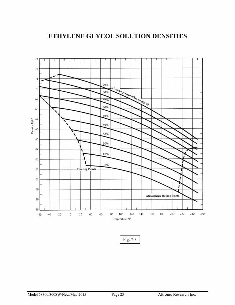
know what the fluid is accurately enough for calorimetry. If your coolant is a mixture of water and ethylene glycol, you cannot be certain what your fluid is until you obtain the specific gravity of your fluid (corrected for temperature) with a laboratory grade hydrometer. Water evaporates from your coolant system, but ethylene glycol doesn't. Therefore, glycol concentrations vary almost daily in an operating system. In systems where fluid loss is made up with water/glycol mixtures, the concentration of glycol gradually increases. Be sure that you know what the specific gravity of your coolant is before you start! Use this value and the Ethylene Glycol Solution Densities chart to

Model 58300/300SW/New/May 2015 Page 21 Altronic Research Inc.
determine the percentage of ethylene glycol in your system. The percentage value is used in the calorimetry process.
Fig. 7-1

Model 58300/300SW/New/May 2015 Page 22 Altronic Research Inc.
Fig. 7-2
Model 58300/300SW/New/May 2015 Page 23 Altronic Research Inc.
ETHYLENE GLYCOL SOLUTION DENSITIES
Fig. 7-3
Model 58300/300SW/New/May 2015 Page 24 Altronic Research Inc.
SECTION VIII
PROGRAM INSTRUCTIONS
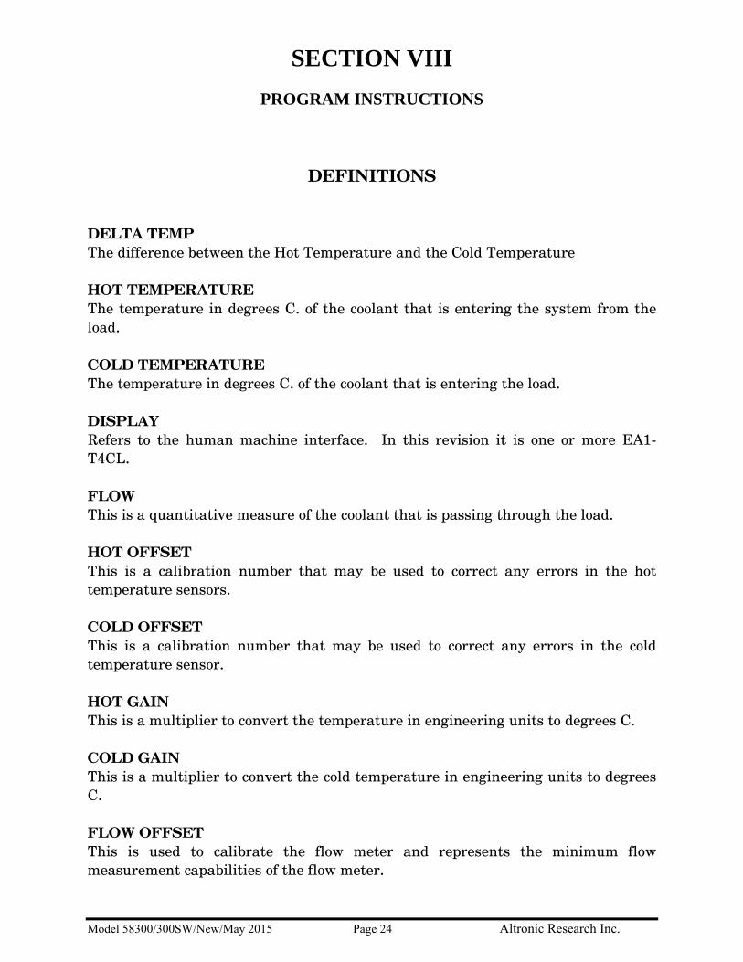
DEFINITIONS DELTA TEMP The difference between the Hot Temperature and the Cold Temperature HOT TEMPERATURE The temperature in degrees C. of the coolant that is entering the system from the load. COLD TEMPERATURE The temperature in degrees C. of the coolant that is entering the load. DISPLAY Refers to the human machine interface. In this revision it is one or more EA1-T4CL. FLOW This is a quantitative measure of the coolant that is passing through the load. HOT OFFSET This is a calibration number that may be used to correct any errors in the hot temperature sensors. COLD OFFSET This is a calibration number that may be used to correct any errors in the cold temperature sensor. HOT GAIN This is a multiplier to convert the temperature in engineering units to degrees C. COLD GAIN This is a multiplier to convert the cold temperature in engineering units to degrees C. FLOW OFFSET This is used to calibrate the flow meter and represents the minimum flow measurement capabilities of the flow meter.

Model 58300/300SW/New/May 2015 Page 25 Altronic Research Inc.
FLOW GAIN This is a multiplier that is used to convert from engineering units to gallons per minute. KT FACTOR The kt factor is a measure of the coolant to transport heat when water is used. This value is .264 and is corrected for temperature changes in the power measurement calculations. If coolants with different values are used, the appropriate kt factor should be entered at the temperature of operation. When a power-on reset is accomplished or the reset push button is pressed, the system will change back to the default value of .264. POWER Power is displayed in KW and is derived from the formula Kt*GPM*DeltaT. SCREEN Refers to the actively shown page on the Display. SOFTKEYS The lower row of almost every screen will display the softkey definitions above the softkeys themselves. The softkeys are permanently labeled F1 to F5. Pressing the softkey or the definition above it have identical effects. For example, touching Alarms or the corresponding F4 key will display the alarms screen.
Softkeys (F1-F5) below their function-definitions.
THE More SOFTKEY In order to provide more than five software defined functions for the softkeys, the More button is used. Pressing More acts as a shift-key to assign additional functions to the softkeys. Repeatedly pressing More will cycle through all available functions. THE Alarms SOFTKEY The Alarms softkey is mapped to F4. See the section on Alarms and Troubleshooters for more information. ACTIVE ALARM INDICATOR (F4 LED) There is an LED built into the F4-softkey which when blinking indicates an active alarm. The F4 LED will continue to blink, in the event of an alarm, even when screens which utilize an alternate F4-softkey definition are displayed.

Model 58300/300SW/New/May 2015 Page 26 Altronic Research Inc.
CONVENTIONS USED IN THIS SECTION Touch responsive controls will be shown by name or description within single quotes ( ' ' ) and whenever possible a graphic will be provided to facilitate identification. Ex: 'CALIBRATION' Softkeys- Softkeys will, whenever possible, be referenced by their definitions and will be highlighted blue.
Ex: Alarms
Occasionally, softkeys may be referenced by an F number in regular font and color.
Ex: F4
If shown in a procedure the arrow ' → ' will indicate to proceed to the next step.

Model 58300/300SW/New/May 2015 Page 27 Altronic Research Inc.
INITIAL SETUP Ensure that all plumbing is complete and mechanical considerations are met before operating the unit. Upon powering the unit the logo splash-screen will be displayed briefly, followed by the main control screen.
Main-Control Screen The LED built into the 'F4' softkey will be blinking indicating active alarms. This condition may be safely ignored while the unit is OFF. Touch the OFF/ON slider switch to turn the unit ON. WARNING: The OFF/ON slider will start the pump and possibly the dry-cooler unit. Make certain that all personnel are clear of moving parts and that the plumbing is properly connected before turning the unit ON.
Main-Control Screen during start up.
A row of lights will appear below the ON/OFF slider indicating the status of the pump-control relay, a positive flow reading, and the state of the interlock relay respectively. If there is no-flow, low-flow, or

Model 58300/300SW/New/May 2015 Page 28 Altronic Research Inc.
widely varied flow during the first 15 seconds of operation the unit will automatically shut down and the Air-Purge screen will be displayed. During initial-setup, air-purging one or more times should be expected. See Section 5 Part 2 Pump Priming Procedure.
Air-Purge Screen When the flow is steady and within acceptable range the display will automatically be changed to the primary-monitoring screen. If the screen does not change automatically touch Monitors → 'Main'.

Model 58300/300SW/New/May 2015 Page 29 Altronic Research Inc.
MAKING POWER MEASUREMENTS
Primary-Monitoring Screen To make a power measurement:
• Start the unit from either the Main-Control screen or from Controls • Ensure that the Alarms (F4) softkey LED is not flashing. • Without RF applied to the unit touch the CALIBRATION button to turn it from OFF to ON.
Calibration button OFF/ON graphic. • Apply RF to the unit.
Power measurements may now be made. WARNING: Never apply RF to the unit:
• Without the transmitter interlock connected, • Without power to the load, • Without the pump started, • Or while there are any Alarms active (F4 softkey LED flashing)

Model 58300/300SW/New/May 2015 Page 30 Altronic Research Inc.
MANUAL CONTROLS In some instances it may be helpful to manually control the load subsystems. The Controls screen offers an easy way to do this.
Controls screen graphic. If turning the system or component on or off is all that is desired, touch the individual switches on the right side of the category buttons. If more information or data is needed, touch the category buttons to switch to the manual-control screen for any of the three categories. The system control screen is shown in the Initial Setup section; the other two screens are shown below.
Fan-Bank Control screen.
Pump Control screen.

Model 58300/300SW/New/May 2015 Page 31 Altronic Research Inc.
MONITOR SCREENS Touch Monitors to select from the following screens:
• Main Monitor • Raw Data • Run Gauges • Heat Monitor • Hi-Vis Power • Flow Monitor
Monitors image index.

Model 58300/300SW/New/May 2015 Page 32 Altronic Research Inc.
GRAPHS Touch Graphs and select from either 'Realtime (20 Second)' or 'Logging (2 Minute)' graphs. All available graphs from each category are listed below:
Real-time Logging • Running Graph • Power • Combo Graph • Temperature • Heat Graph • Flow • Flow Graph
Real-time Heat-Graph with Help information shown. Due to the number of graphs available, images and details of each are omitted from this document for reasons of brevity. For more information on any graph or other screen please use the Help feature which is described in the section titled Help Feature.

Model 58300/300SW/New/May 2015 Page 33 Altronic Research Inc.
ALARMS AND TROUBLESHOOTERS Alarms are triggered by any of the following conditions:
• Over Temperature • Low / No Flow • Over Current • Dry Cooler power is Off. Note: The Dry Cooler being un-powered disables the unit but it does
not cause the F4 LED to blink. Instead a banner message indicating the fault is shown at the top of the screen.
When an alarm is triggered the transmitter interlock will be automatically disengaged and the LED in the F4 softkey will oscillate on and off. A flashing F4 LED indicates active alarms that must be resolved before the unit will start and remain running. NOTE: F4 is defined as the Alarms softkey. Pressing More does not change this functionality. However, in some screens the softkeys are disabled and the associated tab of definitions is not shown. To exit these screens and restore softkey functionality the user must touch the 'Done' button. For alarm status, information, or troubleshooters touch Alarms or the F4 softkey. A screen similar to the one shown below will appear.
Example Alarms screen. Items marked “Fail” are the source of the alarm. Touch any item for information and/or troubleshooters. For example, touching 'Over Temperature' will display the Heat Monitor screen shown in the Monitors section of this document. NOTE: Touching the 'Interlock' button will display the reasons the interlock is not engaged, if any exist, otherwise this screen will be blank.

Model 58300/300SW/New/May 2015 Page 34 Altronic Research Inc.
HELP FEATURE The Help feature offers easy access to additional information for almost every screen available to the user. To turn help on or off touch Help or the associated softkey.
The Help screen. When help is active a '?' button will be shown in the top right corner of most screens. Touching the '?' button will display the associated help screen. As an example touching the '?' help button on the Hi-Vis Power screen would display the following help screen:
Hi-Vis Help screen. RECOMMENDATION: Use the help feature to aid in familiarization with the software before going online with the load.

Model 58300/300SW/New/May 2015 Page 35 Altronic Research Inc.
CONFIGURATION
Config screen. (May appear differently)
NOTE: The values shown in the above graphic are examples and not recommended settings for any particular device. This screen enables the configuration of the system variables for a specific application. To change a specific item, press the screen at that area. When the item is pressed, a calculator-type screen is overlaid. Extra buttons are included for Escape, Backspace, Clear and Entry. After the change has been made, press the “Ent” button to program the data and return to the configuration screen. Preset Configuration data:
Hot Temperature Gain
Hot Temperature Offset
Cold Temperature Gain
Cold Temperature Offset
Flow Sensor 1 Gain
Flow Sensor 1 Offset
Flow Sensor 2 Gain
Flow Sensor 2 Offset
Kt Value
Interval NOTE: These values are calibrated at the factory and should only be changed if the system is reconfigured.

Model 58300/300SW/New/May 2015 Page 36 Altronic Research Inc.
RESETTING DEFAULT CONFIGURATION A user level pass code is required to reset defaults to the above settings. The pass code for this device is: 5623
Load Defaults screen. PROTECTED CONFIGURATION The protected configuration screen facilitates changes to the system in order to rectify unintended or undesirable operation.
Protected Configuration screen. As changes to these settings could cause damage to the load, this screen is protected by a manufacturer-level pass code. Contact customer care for instructions on accessing and safely changing these settings. NOTE: The values shown in the above graphic are examples and not recommended settings for any particular device.

Model 58300/300SW/New/May 2015 Page 37 Altronic Research Inc.
SECTION IX
MAINTENANCE
WARNING!! DO NOT PERFORM MAINTENANCE WITHOUT LOCKING OUT ALL RF ENERGY SOURCES AND NOTIFYING YOUR SUPERVISOR AND ALL TRANSMITTER PERSONNEL THAT YOU ARE DOING SO. FAILURE TO FOLLOW THIS INSTRUCTION MAY RESULT IN FATAL ELECTRICAL SHOCK OR SEVERE BURNS.
9.1. Two Model 157200SB loads are incorporated in this unit, attached to the Main Frame. They are not considered field-repairable and should be returned to Altronic Research for repairs. In the event of mechanical damage to the loads or operational difficulty, contact the factory.
9.2. Calorimetry System. Corrective maintenance of the calorimetry system is limited to
board, assembly and cable replacement at the field level. Refer all other maintenance to a depot level activity or to the manufacturer.
9.3. The Coolant System is composed of a pump, flow meter, flow switch, and the Dry Cooler.
Check coolant level weekly if used intermittently, more frequently if used continuously. If ethylene glycol mixture is used as coolant, the mixture must be periodically verified using a precision hydrometer (range 1.000 to 1.070) or other suitable instrument to prevent the ethylene glycol from becoming too concentrated. A mixture more concentrated than 35% ethylene glycol will lower the efficiency of the unit possibly causing a failure. An acidic condition will cause rapid failure of the resistors. Maintain pH at 6.8-7.8. When there is reason to suspect that the coolant is contaminated, the cooling circuit should be thoroughly flushed with clean water. This should be done by filling the system with clean water and running a short time, then draining and cleaning filter screen. This should be done several times until water is completely clear and filter remains clear of particles. Then refill system with required amount of potable water or approved ethylene glycol mixture.
!!!WARNING!!! USE OF ANYTHING OTHER THAN PURE POTABLE OR DISTILLED WATER OR A MIXTURE OF HIGH QUALITY TECHNICAL GRADE ETHYLENE GLYCOL (i.e. SR1) AND POTABLE WATER WILL VOID THE WARRANTY!

Model 58300/300SW/New/May 2015 Page 38 Altronic Research Inc.
9.4. The Dry Cooler is a COLMAC Model AFV-45162-10.533L-C-G-30-1-BT-D. Inspect quarterly for physical damage to case and coil fins. Open electrical panel at end of Dry Cooler and inspect for insect or rodent infestation or damage. Inspect grommets and conduit fittings for fit and inspect wires for abrasion. Inspect piping for leaks and physical damage.
9.5. Cleaning and Lubrication. Cleaning the Model 58300 / 300 SW is limited to washing and
rinsing painted surfaces. The control box and circuit breaker enclosure are weather resistant but must not be subjected to excessive moisture.
The only device which requires lubrication is the pump motor. Check manufacturer’s requirements

Model 58300/300SW/New/May 2015 Page 39 Altronic Research Inc.
SECTION X
STORAGE
The Model 58300 / 300 SW consists of two major elements for the purpose of storage consideration. The Main Frame contains two Model 157250SB loads, one pump, and associated control systems and plumbing. The Dry Cooler contains one coil, three fans and associated piping and control systems. 10.1. The Main Frame is designed for operation outdoors. It must not be subjected to freezing
temperatures without special preparation. The Main Frame and Dry Cooler share the same coolant. Insure a minimum of 35% ethylene glycol mixture if the possibility exists of freezing temperatures.
Note: Freeze damage is not covered by warranty 10.2. The Dry Cooler does not need special storage measures as long as the fluid which is
trapped in it is maintained at pH above 7.0 and glycol concentration at a minimum of 35%. Care should be taken to disconnect electrical power and prevent the introduction of foreign materials onto the piping.

Model 58300/300SW/New/May 2015 Page 40 Altronic Research Inc.
SCHEMATIC DIAGRAM

Model 58300/300SW/New/May 2015 Page 41 Altronic Research Inc.
SPECIFICATIONS: Model 58300 / 300 SW
Impedance ----------------------------------------------------------------- 300 ohms Balanced Frequency Range --------------------------------------------------------- SW VSWR = 60 Hz to 2.0 MHz --------------------------------------------- 1.15:1 or better Connectors: Model 58300 / 300 SWSB* ------------- Stub or Threaded Stub * -230 after the model number denotes 200-230 VAC 50 / 60 Hz * -460 after the model number denotes 400-480VAC 50/60Hz Coolant Type --------------------------------- Potable water or 30% ethylene glycol mixture Power Rating -------------------------------------------------------------- 300 KW Cont.
Ambient Temperature vs. Power Ratings:
300kW continuous: 30% Ethylene Glycol coolant --------------- -20°C to +50°C (-4°F to +122°F) Pump 3 HP Centrifugal AC Power Requirements: 400-480 VAC, Three Phase, 60Hz Serial No.________________________Frequency__________________Resistance_________ Model________________________________Inspected by___________Date________________
CRAFTED WITH PRIDE IN ARKANSAS, U.S.A.

Model 58300/300SW/New/May 2015 Page 42 Altronic Research Inc.
SPECIFICATIONS Model 157200
Impedance
150 ohm nominal
Maximum Power Rating
150 KW
Maximum VSWR
Not specified
Coolant Ordinary tap or pure water; Ethylene Glycol and water mixture 35%
Water Connectors
NPT Female
Min. Water Flow Rate
19-GPM
Input Water Temperature
4°C to 45°C
Output Water Temperature
Maximum: 90°C
Maximum Inlet Pressure
100 PSI Max.
Resistor
Cylindrical film type-field replaceable
Input Connectors
3-1/8-16 x 1/2" Stub
Dimensions (nominal)
14-1/2" x 40"
Weight
52 lbs.
Operating Position
Any
Finish
Nickel Plate
DC Resistance
Serial No.
Date

Model 58300/300SW/New/May 2015 Page 43 Altronic Research Inc.
Appendix A
Coolant Specifications
COOLANT
COOLANT - The OMEGALINE® dummy load may be used with ordinary tap water, pure, or de-ionized water in open or closed cooling systems. The use of deionized and distilled water in OMEGALINE® loads has been reported to cause premature failures under some conditions. These failures are the result of the leaching action of the coolant on the silver and silver-plated surfaces of the resistors and contact material. The reported failures have generally been associated with deionized systems which are polished to 10-15 megohm levels and are operated intermittently. We suspect that the failure mechanism is attributable to bacterial growth in the coolant system and the subsequent high levels of sulfides usually found in conjunction with such contamination. Altronic does offer a line of water-cooled loads with gold and gold-plated resistors and contacts, for use in systems where leaching action seems unavoidable. Contact our sales office for information. We suggest the use of caution when determining what coolant to use. Potable water is certainly the most desirable coolant. Brackish or salt water is NOT permissible as a coolant for the load resistor! The load is designed with non-contaminating elements in the water circuit and may be used with transmitters that have pure water recirculating cooling systems. For operation below the freezing temperatures of water, ethylene glycol may be added to the water to prohibit freezing (see Fig. 3). If you have questions about coolants, please consult the factory.
IMPORTANT We recommend a Glycol mixture of 30% (3:10) or less. Addition of ethylene glycol to water reduces the heat capacity of the mixture with a corresponding reduction in cooling effectiveness. Therefore, the coolant flow rate should be increased approximately 20% from that required with water only.
!!!WARNING!!! Only clear, colorless analytic or technical grade ethylene glycol may be used. Dow Chemical Company's Dowtherm® SR1 has been reported to be fully compatible with OMEGALINE® loads when used in accordance with Dow's instructions (up to a 40% max). DO NOT use any stop leak, sealants, automotive antifreeze or Union Carbide Ucartherm™ in coolant. To do so will void the warranty. Damage to the resistor film may occur with applied power, resulting in failure!

Model 58300/300SW/New/May 2015 Page 44 Altronic Research Inc.
CONCENTRATION OF COOLANT FREEZING POINT
BOILING POINT
Glycol: Water Parts by Volume at Room Temp.
% Glycol by Volume
% Glycol by Weight
°C
°F
°C
°F
(pure water) 0 0 0 32 100 212 3:7 30 32.3 -16 2 104 219 2:3 40 42.7 -26 -15 106 222 1:1 50 52.7 -40 -40 109 228
Fig. 3 Freezing and Boiling Points of Glycol-Water Mixtures
TEMPERATURE RANGE - The impedance of the load is practically independent of glycol-water mixture, water flow rate, and water temperature. A wide range of input water temperatures (0°C to 60°C) may be used as long as the output water temperature is not allowed to exceed 90° C. DETERMINATION OF GLYCOL CONCENTRATION –
• Obtain a 500 ml sample of the coolant to be tested and place in the hydrometer jar. • Place the thermometer in the jar and allow the temperature reading to stabilize. • Read the thermometer and record the reading. • Place the hydrometer in the jar and allow to settle. Read the hydrometer and record the
reading. • See the table in Fig. 3A to determine the glycol concentration.

Model 58300/300SW/New/May 2015 Page 45 Altronic Research Inc.
Glycol Concentration Table

Model 58300/300SW/New/May 2015 Page 46 Altronic Research Inc.
Water, Glycols and Resistors A Tale of Compatibility
by James L. Keyes
Table of Contents I. Background II. Resistors III. Water IV. Glycols V. Chemical Additives VI. Recap I. BACKGROUND The removal of heat from industrial and electronic devices has engaged engineers almost from the start of the modern industrial age. It seems a never-ending battle, as the trend toward miniaturization and lighter materials has given us smaller devices which produce more waste heat per unit of mass. This general problem for industry is a special problem for resistive load manufacturers. It has been less than fifty years since the film resistor with direct fluid cooling was introduced to the industry. Great advances in film technology and materials have brought us to the point that the direct liquid-cooled load is a standard part of thousands of radio and television stations, every linear accelerator and varied industrial RF heating systems. In spite of new designs, better materials and modern manufacturing techniques, there has remained one constant: the best coolant is plain old water. II. RESISTORS Resistors have progressed from the early tin oxide film devices, often built on glass or quartz forms to ceramic-metallic film types built on beryllium or alumina forms. They are available in rod, plate and tube forms. For our discussion, we assume the tube form, but the thermal principles are the same for all shapes. The manufacture of the resistor involves the deposition of conductive bands of metal for contact points, application of resistive material between the bands and application of a protective coating over the resistive material. For the most part, the bands are silver. Some platinum, palladium or other element may be added for improved strength or corrosion resistance, but the band is at least 95% silver. This is a real strength, as oxidation of most metals creates an insulator, but silver oxidizes to silver oxide, an excellent conductor. III. WATER Water is a real enigma for engineers in the heat transfer business. It is the most effective heat transfer fluid for almost any application imaginable, but it freezes or boils at the worst possible times, supports the growth of algae and slime bacteria, dissolves all manner of contaminants [and carries them to places where they don’t belong!], deposits soluble minerals on heat-producing elements and becomes an acid medium over time. We filter it, chlorinate it and pipe it around our cities, calling it clean, potable and good to drink. When we analyze it, we find that it is a veritable chemical cocktail, because water is a universal solvent and has been busy dissolving the iron pipes used to carry it, the iron ions have fed iron-reducing bacteria which are quite immune to the chlorine and the chlorine has reacted with the dissolved organics to produce nitrosamines and other secondary contaminants.

Model 58300/300SW/New/May 2015 Page 47 Altronic Research Inc.
Typical of good engineers, we have attacked those problems with distillation systems and de-ionization systems. We have produced distilled water which is so pure that it dissolves glass labware, but we can’t keep it free of contaminants. With modern reverse osmosis plants and activated charcoal filters we have produced millions of gallons of ultra-pure D.I. water and piped it about in elaborate chilled coolant systems. But it still grows bacteria rather well! The two contaminants in water which we are most likely to see are slime bacteria and algae. Algae is the green stuff you see growing in ponds in the summer time. It needs heat and light to grow well. With algae, what you see is what you get. The principal problem it presents is the mat of filamentous material which clogs pumps and filters. Slime bacteria are any of several genera of bacteria. They don’t need any light and will grow in very cold conditions. Like any bacteria, the individuals in a colony have very short lives. When they die, they decay and produce hydrogen sulfide [H2S] and some solids. The hydrogen sulfide dissolves in the water and becomes sulphurous acid [H2SO3]. The solids show up in filters as fine black sediment with a ‘pond’ smell. When the slime bacteria problems appeared in distilled water systems on board U. S. Navy vessels in the early 20th century, the solution was simply to add potassium permanganate to the water. [The water was intended for boiler feed water and small amounts of potassium were unimportant, whereas chlorine would have been a major problem.] As time and science progressed, D.I. water changed from a laboratory curiosity to a required part of klystron cooling systems, due to its very low conductivity. The operators of large D.I. water systems were very successful as long as the systems were kept in continuous operation. They often found that the systems were out of specification after weekend or holiday shutdowns. Complaints of excessive filter changes and large increases in resin cylinder requirements following shutdowns began to surface. Soon a national laboratory found that all of the silver was gone from several resistors cooled by the D.I. system. This triggered a major investigation and, subsequently, retrofit of many resistive loads with gold-plated components. IV. GLYCOLS It has been observed that many systems using 20% to 50% inhibited ethylene glycol have been operated for years without bacteria or algae problems. Thus, some have ascribed some magical anti-bacterial property to ethylene glycol and decided that it is a great way to avoid the algae/bacteria problems. In a way, that is true, but...the glycols really have no demonstrated algacidal or bactericidal properties! In fact the common glycols [ethylene and propylene] are biodegradable under aerobic conditions. They are food for some common bugs which are probably already in the feedwater! It’s the corrosion inhibitor package used to protect the metals in the system that really suppresses the bugs. The most common inhibitor is dipotassium phosphate. There’s that potassium again! The Navy boilermen knew the answer all along! We have extensive experience with the inhibitor package in DOWTHERM7 SR-1. Thousands of resistors run in this formulation with no problem. Unfortunately, we cannot say the same thing for UCARTHERM7. There is some difference in the inhibitor package which causes deposits to build up on the resistor and early failure of the load. Despite several years of collaboration with Union Carbide chemists we have found no solution for this problem. The principal problem presented by coolant with ethylene glycol added is the drastic loss of cooling capacity. 50% glycol costs you one-third of your cooling capacity. You must either derate your or overbuild your cooling system. Added to that are pumping losses for the higher viscosity fluid, annual maintenance costs, etc.
Model 58300/300SW/New/May 2015 Page 48 Altronic Research Inc.
V. CHEMICAL ADDITIVES I’m not a chemist, so all I can tell you is what I have observed in a long career of water management. 1. Most inorganic additives will increase the conductivity of the coolant. As an example, here are the data for DOWTHERM7 SR-1 for 25C: % Glycol [by weight] Conductivity [mhos/cm]
0 9.69 x 10^-7
12.5 2.45 x 10^-3
25.0 3.48 x 10^-3
50.0 3.42 x 10^-3
100.0 8.66 x 10^-3
2. If this is undesired, use only enough inhibitor to maintain pH in the 7.0 to 7.4 range and use organic algaecide and organic bacteriastatic additives. ICI Americas sells an excellent line of products for swimming pool and spa maintenance [BAQUACIL and BAQUASTAT 50]. Other companies may have similar products. These are known to me to be quite benign and safe for use with silver-bearing components. VI. RECAP The maintenance of a closed loop water system is a challenge, but not rigorous once the principles are understood. The object is to remove heat from something and get rid of it. In order to protect the components of the system, we need to maintain control of pH, algae and bacteria growth and conductivity. Use dipotassium phosphate to raise the pH, use organic algaecide and organic bacteriastat to control the bugs and learn to live with the resultant conductivity. If that becomes an issue, use distilled water for the base and makeup water. Just remember that an acidic pH is going to give you problems and an untreated system is an uncontrolled system.