Embed Size (px)
Citation preview

ALTRAD BarOmix COMMODORE
5/3½, 7/5 & 10/7 Model CEMENT MIXERS
Operator’s Manual
ALTRAD BarOmix Ltd. The Mill Industrial Park, Kings Coughton, Alcester, B49 5QG Tel: +44(0) 1789 400211 Fax: +44(0) 1789 400216 e-mail [email protected]
Web: www.altrad.com/gb
August 2005
Commodore CONTENTS 1 SECTION: 1 Introduction and Purpose 2 Technical Specifications, Dimensions and Noise Level 3 Safety and Symbols 3.1 Ensure! 3.2 Never! 3.3 Always! 3.4 Safety controls 3.5 Symbols on machine 4 Machine Preparation 4.1 Transporting 4.2 Lifting 4.3 Parking 4.4 Parking (Highway Tow model) 4.5 Filling fuel tank 5 Operation 5.1 Pre-work checks 5.2 Starting machine 5.3 Stopping machine 5.4 Mixing 5.5 On completion of work 6 Maintenance Routine Maintenance schedule 6.1 lubrication points 6.2 Engine Oil 6.3 Fasteners 6.4 Battery 6.5 Brakes (Highway Tow model) 6.6 Tyres and Wheels 6.7 Wheels (Highway Tow model) 6.8 Drum drive chain 6.9 Drum inner bearing
6.10 Drum removal 7 Storage 7.1 Storage 7.2 Removal from storage 8 Disposal
©ALTRAD BarOmix - 1 - 08/05
Commodore 1. INTRODUCTION AND PURPOSE 1-1 INTRODUCTION This manual explains the proper operation of your machine. Read these instructions thoroughly before operating and maintaining the machine. Failure to do so could result in personal injury or equipment damage. Consult your Altrad BarOmix supplier if you do not understand the instructions in this manual. Important note: For operation and maintenance of the power unit, ALWAYS refer to the instructions on the unit itself and in the separate manual supplied with the machine. This manual does not include specific instructions for the power unit. Any instructions in this manual referring to an engine are for general example only. The power unit fitted may be a different diesel or petrol engine from the one shown or an electric motor.
CAUTION! This symbol indicates important safety messages in this manual. When you see this symbol, be alert to the possibility of injury to yourself or others, and carefully read the message that follows and carry out the action that requires attention.
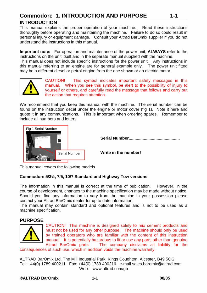
We recommend that you keep this manual with the machine. The serial number can be found on the instruction decal under the engine or motor cover (fig 1). Note it here and quote it in any communications. This is important when ordering spares. Remember to include all numbers and letters.
Serial Number............................................
Write in the number!
This manual covers the following models. Commodore 5/3½, 7/5, 10/7 Standard and Highway Tow versions The information in this manual is correct at the time of publication. However, in the course of development, changes to the machine specification may be made without notice. Should you find any information to vary from the machine in your possession please contact your Altrad BarOmix dealer for up to date information. The manual may contain standard and optional features and is not to be used as a machine specification. PURPOSE
CAUTION! This machine is designed solely to mix cement products and must not be used for any other purpose. The machine should only be used by trained operators who are familiar with the content of this instruction manual. It is potentially hazardous to fit or use any parts other than genuine Altrad BarOmix parts. The company disclaims all liability for the
consequences of such use, which in addition voids the machine warranty.
Fig 1 Serial Number
Serial Number
ALTRAD BarOmix Ltd. The Mill Industrial Park, Kings Coughton, Alcester, B49 5QG Tel: +44(0) 1789 400211 Fax: +44(0) 1789 400216 e-mail [email protected]
Web: www.altrad.com/gb
©ALTRAD BarOmix 1-1 08/05

Commodore 2. SPECIFICATIONS 2-1
Fig 2.1 Commodore Mixer Main Features
Drawbar
Engine Canopy
Drum
Handwheel
Fork Lift
Frame
Handwheel Lock
Sling arm Lift Point
Blade
TECHNICAL SPECIFICATION Commodore Standard and Highway Tow models Batch capacity 5/3½ 7/5 10/7 Unlimited Dry (Lt) 150 210 300 Mixed Wet (Lt) 105 150 210 Drum Speed (Rev/min) 24 24 24 Power Unit – diesel engine Lister LV1 Hand start air cooled
Yanmar electric start with recoil back-up Power Unit – petrol engine Honda GX 120 Power Unit – electric motor Single phase 110V or 240V
or 3 phase 400/440V e.f.c Length (mm) 1700 1700 1850 Width (mm) 780 780 1140 Height (mm) 1640 1640 1640 Weight (kg) 390 440 600 Drum discharge height (mm) 660 660 510 - Mouth diameter (mm) 430 430 500 - Loading height (mm) 1140 1140 1240 Highway Tow 5/3½ 7/5 10/7 Length (mm) 2260 2310 2410 Width (mm) 1270 1270 1260 Height (mm) 1470 1470 1670 Weight (kg) 460 500 660 Drum discharge height (mm) 610 580 580 - Mouth diameter (mm) 430 430 500 - Loading height (mm) 1090 1170 1120 *Dimensions subject to confirmation
©ALTRAD BarOmix 2-1 08/05
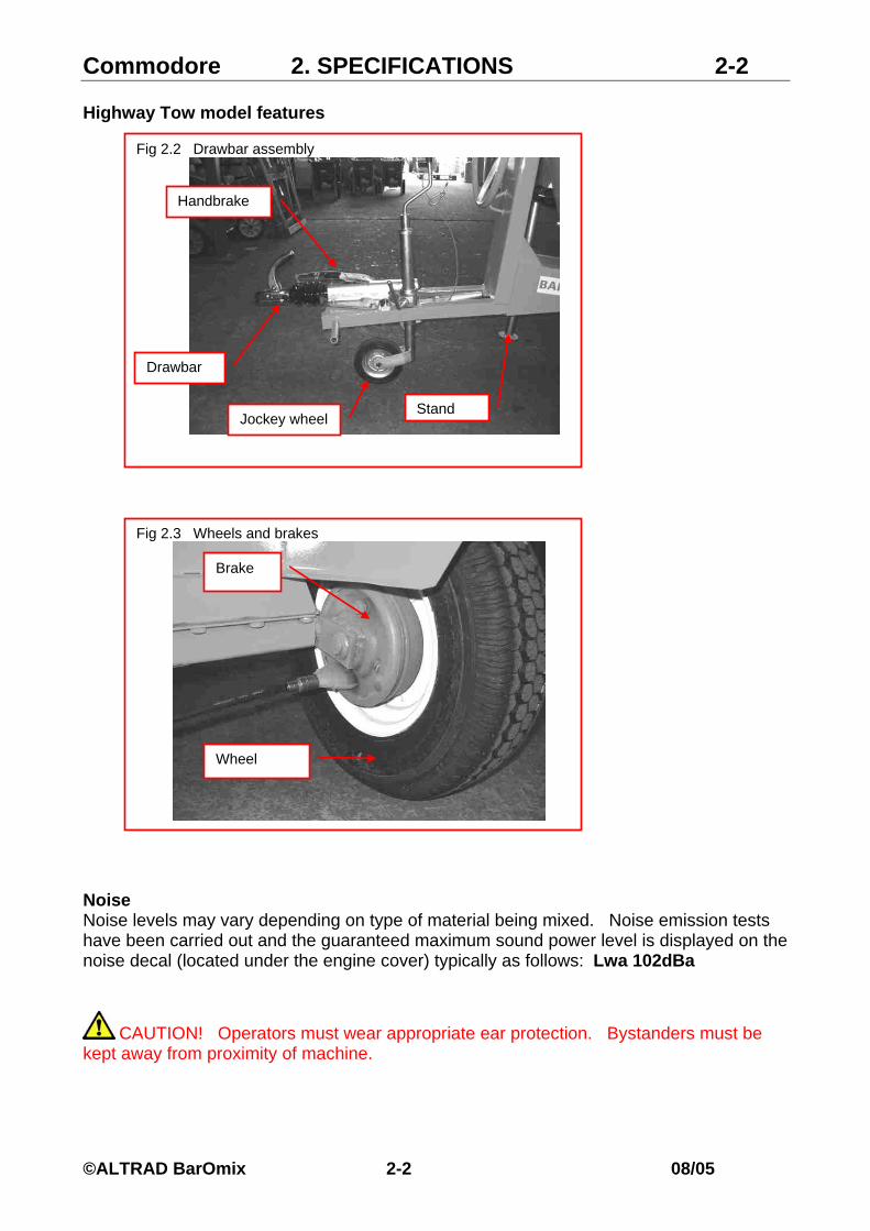
Commodore 2. SPECIFICATIONS 2-2 Highway Tow model features
Fig 2.2 Drawbar assembly
Drawbar
Handbrake
Stand Jockey wheel
Fig 2.3 Wheels and brakes
Brake
Wheel
Noise Noise levels may vary depending on type of material being mixed. Noise emission tests have been carried out and the guaranteed maximum sound power level is displayed on the noise decal (located under the engine cover) typically as follows: Lwa 102dBa
CAUTION! Operators must wear appropriate ear protection. Bystanders must be kept away from proximity of machine.
©ALTRAD BarOmix 2-2 08/05
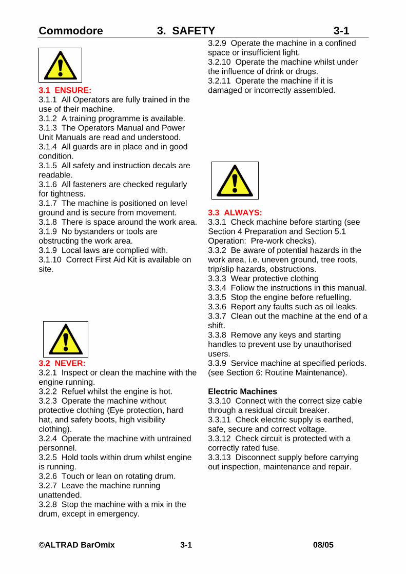
Commodore 3. SAFETY 3-1 3.1 ENSURE: 3.1.1 All Operators are fully trained in the use of their machine. 3.1.2 A training programme is available. 3.1.3 The Operators Manual and Power Unit Manuals are read and understood. 3.1.4 All guards are in place and in good condition. 3.1.5 All safety and instruction decals are readable. 3.1.6 All fasteners are checked regularly for tightness. 3.1.7 The machine is positioned on level ground and is secure from movement. 3.1.8 There is space around the work area. 3.1.9 No bystanders or tools are obstructing the work area. 3.1.9 Local laws are complied with. 3.1.10 Correct First Aid Kit is available on site.
3.2 NEVER: 3.2.1 Inspect or clean the machine with the engine running. 3.2.2 Refuel whilst the engine is hot. 3.2.3 Operate the machine without protective clothing (Eye protection, hard hat, and safety boots, high visibility clothing). 3.2.4 Operate the machine with untrained personnel. 3.2.5 Hold tools within drum whilst engine is running. 3.2.6 Touch or lean on rotating drum. 3.2.7 Leave the machine running unattended. 3.2.8 Stop the machine with a mix in the drum, except in emergency.
3.2.9 Operate the machine in a confined space or insufficient light. 3.2.10 Operate the machine whilst under the influence of drink or drugs. 3.2.11 Operate the machine if it is damaged or incorrectly assembled.
3.3 ALWAYS: 3.3.1 Check machine before starting (see Section 4 Preparation and Section 5.1 Operation: Pre-work checks). 3.3.2 Be aware of potential hazards in the work area, i.e. uneven ground, tree roots, trip/slip hazards, obstructions. 3.3.3 Wear protective clothing 3.3.4 Follow the instructions in this manual. 3.3.5 Stop the engine before refuelling. 3.3.6 Report any faults such as oil leaks. 3.3.7 Clean out the machine at the end of a shift. 3.3.8 Remove any keys and starting handles to prevent use by unauthorised users. 3.3.9 Service machine at specified periods. (see Section 6: Routine Maintenance). Electric Machines 3.3.10 Connect with the correct size cable through a residual circuit breaker. 3.3.11 Check electric supply is earthed, safe, secure and correct voltage. 3.3.12 Check circuit is protected with a correctly rated fuse. 3.3.13 Disconnect supply before carrying out inspection, maintenance and repair.
©ALTRAD BarOmix 3-1 08/05

Commodore 3. SAFETY 3-2
Fig 3.4.1 Engine Stop (Yanmar)
Stop lever
3.4 Safety Controls.
CAUTION! Power units may be different from example shown. Read instructions for engine or motor before use.
3.4.1 Engine Stop (fig 3.4.1)
Stop the engine as follows: Yanmar: Depress red lever. (fig 3.4.1) Lister: Turn knob anticlockwise. (fig 3.4.2) Except in emergency, always empty drum before stopping engine.
Fig 3.4.2 Engine stop (Lister)
Stop knob
3.4.2 Electric Motor (alternative) Depress STOP button and disconnect supply.
CAUTION! Do not restart until hazard has been removed.
©ALTRAD BarOmix 3-2 08/05

Commodore 3. SAFETY 3-3 3.5 SYMBOLS on the MACHINE Before use read and familiarize all instruction decals on machine and power unit. Important! See separate manual for symbols on engine or electric motor. 3.5.1 Large decal under engine cover gives brief operating instructions and machine serial number. Write this number into Section 1 Fig 3.5.1 Operating decal
Serial Number
3.5.2 Noise level decal. See Section 1 for noise statement. 3.5.3 Lifting points are indicated by 'Fork Lift' and ‘Sling Here' decals. See section 4.2 for instructions Fig 3.5.2 Noise level decal Fig 3.5.3 Lifting Decals
©ALTRAD BarOmix 3-3 08/05

Commodore 4. HANDLING & PREPARATION 4-1
4.1 Transporting 4.1.1 Use a lorry or trailer to transport the machine any distance. Highway tow machines may be transported by drawbar. Fig 4.2 Lifting points
4.1.2 Highway tow only. Check drawbar and tyres and brakes before towing on the road. Ensure stand is raised and secure.
Lifting eye
Fork points
CAUTION! Suitable chains, straps or ropes must be used to secure machine to a lorry or trailer. 4.2 Lifting (fig 4.2) 4.2.1 Turn the drum fully downwards and lock handle. 4.2.2 Secure drawbar to handwheel. 4.2.3 Sling from lifting eye or use fork lift points under frame. Fig 4.3 Parking the drawbar
4.3 Parking (fig 4.3) Brake 4.3.1 Position the machine on level ground. 4.3.2 Apply brake to tyre. 4.3.3 Swing drawbar underneath frame to remove trip hazard. 4.3.4 Check machine is secure from any movement.
Drawbar
4.3.5 Clear any obstructions from the work space. 4.3.6 To move the machine, reverse this procedure. 4.4 Parking Highway Tow model (fig 2.2) 4.4.1 Position on level ground. 4.4.2 Apply handbrake (fig 2.2) Fig 4.5 Fuel tank
Yanmar
4.4.3 Level machine with jockey wheel adjuster. Fuel Filler
4.4.4 Set and clamp stand. 4.4.5 Ease jockey wheel to transfer weight to stand. 4.4.6 To move machine, reverse this procedure. 4.5 Filling fuel tank (fig 4.5)
Lister 4.5.1 Lift engine cover.
4.5.2 Fill the fuel tank with correct fuel for the type of engine. See power unit instructions.
Fuel Filler
4.5.3 Lower engine cover. 4.6 Electric Supply (Electric motor only) 4.6.1 Check that there is a safely earthed supply at correct voltage to reach motor. Incorrect voltage may damage motor.
©ALTRAD BarOmix 4-1 08/05
Commodore 5. OPERATION 5-1
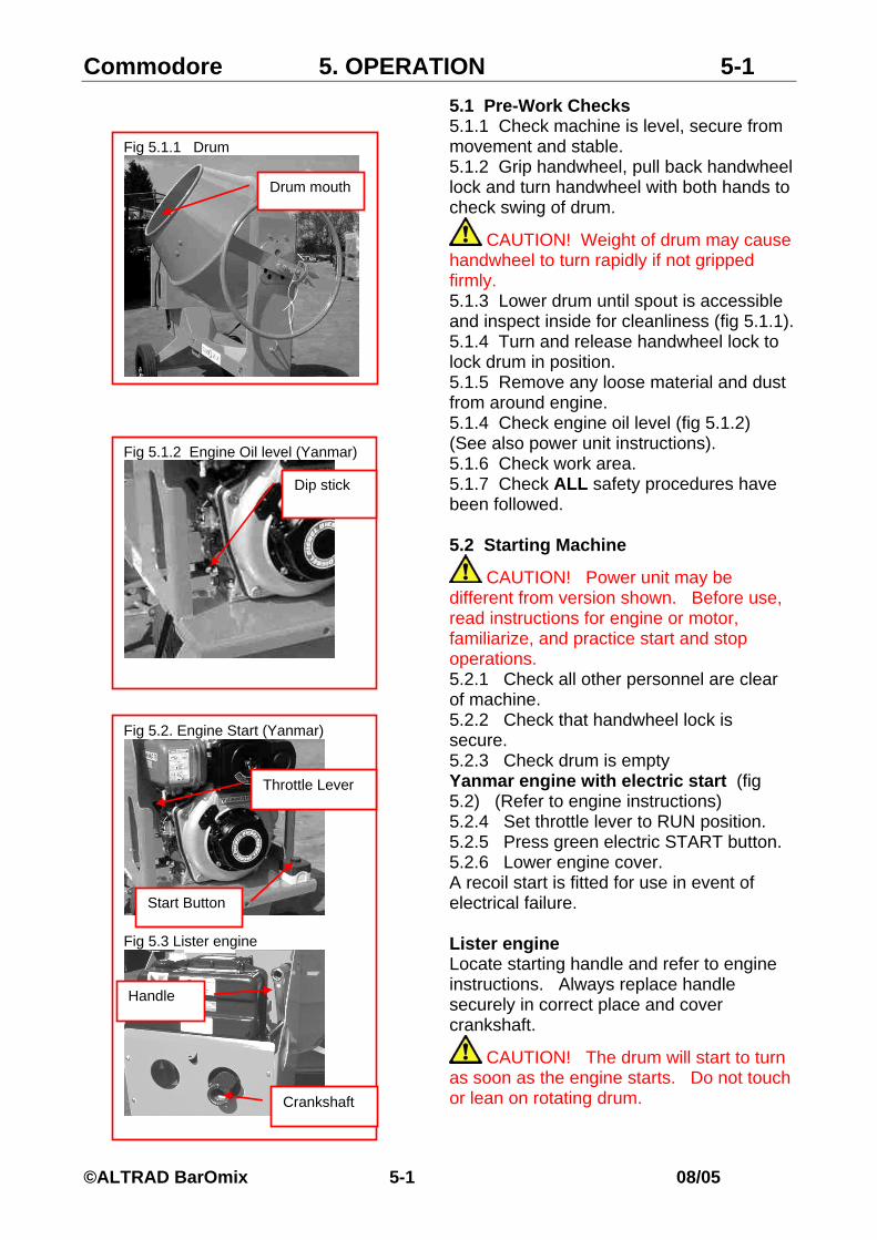
5.1 Pre-Work Checks 5.1.1 Check machine is level, secure from movement and stable. Fig 5.1.1 Drum
5.1.2 Grip handwheel, pull back handwheel lock and turn handwheel with both hands to check swing of drum.
Drum mouth
CAUTION! Weight of drum may cause handwheel to turn rapidly if not gripped firmly. 5.1.3 Lower drum until spout is accessible and inspect inside for cleanliness (fig 5.1.1). 5.1.4 Turn and release handwheel lock to lock drum in position. 5.1.5 Remove any loose material and dust from around engine. 5.1.4 Check engine oil level (fig 5.1.2) (See also power unit instructions). Fig 5.1.2 Engine Oil level (Yanmar)
5.1.6 Check work area. 5.1.7 Check ALL safety procedures have been followed.
Dip stick
5.2 Starting Machine
CAUTION! Power unit may be different from version shown. Before use, read instructions for engine or motor, familiarize, and practice start and stop operations. 5.2.1 Check all other personnel are clear of machine. 5.2.2 Check that handwheel lock is secure. Fig 5.2. Engine Start (Yanmar)
5.2.3 Check drum is empty Yanmar engine with electric start (fig 5.2) (Refer to engine instructions) 5.2.4 Set throttle lever to RUN position. 5.2.5 Press green electric START button. 5.2.6 Lower engine cover. A recoil start is fitted for use in event of electrical failure.
Fig 5.3 Lister engine Lister engine
Throttle Lever
Start Button
Crankshaft
Handle
Locate starting handle and refer to engine instructions. Always replace handle securely in correct place and cover crankshaft.
CAUTION! The drum will start to turn as soon as the engine starts. Do not touch or lean on rotating drum.
©ALTRAD BarOmix 5-1 08/05

Commodore 5. OPERATION 5-2
5.3 Stopping Machine 5.3.1 Ensure drum is empty (except in emergency).
Fig 5.4.1 Drum discharge
Handwheel 5.3.3 Press RED lever or button to stop engine or motor. See Section 3 (fig 3.4). 5.3.4 Wait for machine to stop. 5.4 Mixing 5.4.1 Position drum as in fig 5.1. 5.4.2 Load water first. 5.4.3 Load approximately half the aggregates (stone).
CAUTION! Do not put shovel into drum. Keep tools clear of mouth. 5.4.4 Load cement. 5.4.5 Load sand. 5.4.6 Allow sand and cement to mix for approximately 30secs. 5.4.7 Load remainder of aggregate. 5.4.8 Allow mixing to complete, time will depend on mix proportions. 5.4.9 Grip handwheel, pull back handwheel lock and rotate to discharge mix (fig 5.4.1). 5.4.10 Release handwheel lock to secure drum.
CAUTION! Unbalanced drum may cause handwheel to rotate rapidly unless gripped firmly. Note: Mix may be discharged to either side of machine (fig 5.4.2).
CAUTION! Keep work area around the machine clear at all times and check only authorised personnel are present. 5.5 On Completion Of Work 5.5.1 Thoroughly wash out drum with engine running. 5.5.2 Stop engine. 5.5.3 Clean down machine. 5.5.4 Park drum downwards (fig 5.5). 5.5.5 Move machine to release wheels from any mix residue on the ground.
Fig 5.5 Drum storage position
Mouth
Blades
Fig 5.4.2 Typical drum positions Load and mix to left
Discharge to left
Load and mix to right
Discharge to right
©ALTRAD BarOmix 5-2 08/05
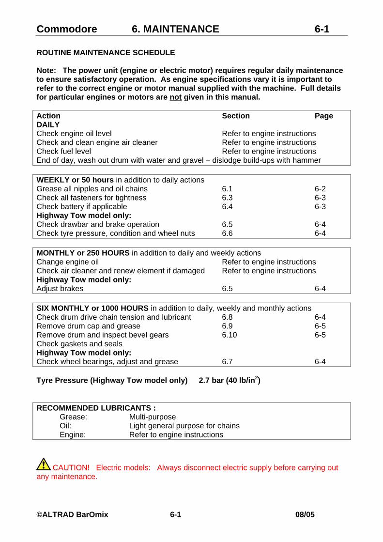
Commodore 6. MAINTENANCE 6-1 ROUTINE MAINTENANCE SCHEDULE Note: The power unit (engine or electric motor) requires regular daily maintenance to ensure satisfactory operation. As engine specifications vary it is important to refer to the correct engine or motor manual supplied with the machine. Full details for particular engines or motors are not given in this manual. Action Section Page DAILY Check engine oil level Refer to engine instructions Check and clean engine air cleaner Refer to engine instructions Check fuel level Refer to engine instructions End of day, wash out drum with water and gravel – dislodge build-ups with hammer WEEKLY or 50 hours in addition to daily actions Grease all nipples and oil chains 6.1 6-2 Check all fasteners for tightness 6.3 6-3 Check battery if applicable 6.4 6-3 Highway Tow model only: Check drawbar and brake operation 6.5 6-4 Check tyre pressure, condition and wheel nuts 6.6 6-4 MONTHLY or 250 HOURS in addition to daily and weekly actions Change engine oil Refer to engine instructions Check air cleaner and renew element if damaged Refer to engine instructions Highway Tow model only: Adjust brakes 6.5 6-4 SIX MONTHLY or 1000 HOURS in addition to daily, weekly and monthly actions Check drum drive chain tension and lubricant 6.8 6-4 Remove drum cap and grease 6.9 6-5 Remove drum and inspect bevel gears 6.10 6-5 Check gaskets and seals Highway Tow model only: Check wheel bearings, adjust and grease 6.7 6-4 Tyre Pressure (Highway Tow model only) 2.7 bar (40 lb/in2) RECOMMENDED LUBRICANTS : Grease: Multi-purpose Oil: Light general purpose for chains Engine: Refer to engine instructions
CAUTION! Electric models: Always disconnect electric supply before carrying out any maintenance.
©ALTRAD BarOmix 6-1 08/05

Commodore 6. MAINTENANCE 6-2 6.1 Lubrication Points
Fig 6.1 1 Lubrication Points
6.1.1
6.1.5
6.1.6
6.1.7
6.1.2
6.1.8
6.1.3 6.1.4
Grease except where stated 6.1.1 Swing arm (trunnion) bearing 1 nipple 6.1.2 Drive shaft bearing 1 nipple 6.1.3 Drum drive 1 nipple 6.1.4 Drum bearing 1 nipple 6.1.5 Handwheel lock Smear with grease 6.1.6 Handwheel bearing 1 nipple 6.1.7 Wheel spindles Smear with grease 6.1.8 Drum bearing (from inside) Remove cover, pack with grease 6.1.9 Chains Oil
Highway Tow only Fig 6.1.2 Drawbar (Highway Tow)
6.1.9
6.1.10
6.1.10 Drawbar Nipple 6.1.11 Jockey wheel Nipple 6.1.12 Wheels (fig 6.5) Grease
©ALTRAD BarOmix 6-2 08/05

Commodore 6. MAINTENANCE 6-3
6.2 Engine Always refer to engine or motor instructions! Daily 6.2.1 Check oil (fig 6.2.1) and air cleaner (fig 6.2.2) Fig. 6.2.1 Engine oil (Yanmar)
Dipstick
Drain plug
Monthly 6.2.2 Drain and replace oil. 6.2.3 Replace air cleaner element. 6.3 Fasteners Weekly 6.3.1 Check all components and fasteners for tightness. Pay special attention to drum blades and other rotating components.
CAUTION! Operation with loose components is hazardous. Fig.6.2.2 Air cleaner (Yanmar)
Air cleaner 6.4 Battery (fig 6.4) Machines with electric start include a battery situated under the engine platform. First 50 hours and then weekly 6.4.1 Remove cover 6.4.2 Slide out battery to access top. 6.4.3 Check electrolyte level and top up if required. 6.4.4 Slide back and replace cover. Fig 6.4 Battery
CAUTION! Gases are explosive. Electrolyte is corrosive. Avoid sparks and spillage.
CAUTION! Always remove negative lead before positive when disconnecting battery. Battery
©ALTRAD BarOmix 6-3 08/05

Commodore 6. MAINTENANCE 6-4
6.5 Brakes (Highway Tow only) Weekly: Check operation and effectiveness of overrun and handbrake. 6.5.1 Push drawbar to feel resistance. Fig 6.5 Brakes (Highway Tow) 6.5.2 Apply handbrake to feel resistance. Monthly 6.5.3 Adjust brakes as follows. 6.5.3.1 Chock machine, release handbrake and check drawbar is fully extended. 6.5.3.2 Support both wheels off ground on axle stands. Brake
adjuster 6.5.3.3 Rotate each wheel forwards and turn brake adjuster clockwise until tight (fig 6.5). 6.5.3.4 Check brake linkage is free from slack.
6.5.3.5 Back off one notch and check wheel is free and repeat for opposite wheel.
CAUTION! Reverse rotation of wheel may prevent correct adjustment. 6.6 Tyres and Wheels Weekly 6.6.1 Check condition of tyres. Highway Tow model only: 6.6.2 Check pressures and inflate to 2.7bar (40lb/in2) pressure as required. 6.6.3 Check wheel nuts are tight to 110Nm (80lbft) torque. 6.7 Wheels (Highway Tow model only) Six monthly 6.7.1 Remove grease cap from hub. 6.7.2 Adjust bearings if required. 6.7.3 Repack with grease and replace cap.
Fig 6.8 Drum drive chain
Adjuster
Cover
6.8 Drum drive chain adjustment (fig 6.8) Six monthly 6.8.1 Remove cover to oil chain (weekly). 6.8.2 Slacken adjuster nut. 6.8.3 Reset adjuster to tighten chain. 6.8.4 Secure nut and replace cover.
©ALTRAD BarOmix 6-4 08/05

Commodore 6. MAINTENANCE 6-5
Fig. 6.9 Drum inner bearing
Bearing cover
6.9 Drum inner bearing (fig 6.9) Six monthly 6.9.1 Remove cover inside drum. 6.9.2 Clean and repack with grease. 6.9.3 Check seal and replace cover.
6.10 Drum removal Six monthly
To inspect bevel gears the drum is removed from the sling arm.
Fig 6.10 Pinion
Pinion
6.10.1 Position drum mouth upwards. 6.10.2 Secure drum with suitable lifting tackle or an overhead crane.
6.10.3 Remove nut. 6.10.4 Carefully lift drum clear of sling arm. 6.10.5 Inspect gears (fig 6.10), clean and regrease.
6.10.6 Replace drum and secure nut.
©ALTRAD BarOmix 6-5 08/05

Commodore 7. STORAGE 7-1 7.1 Storage 7.1.1 Thoroughly clean machine and note any replacement parts required. 7.1.2 Carry out monthly service if not already done. Refer to Section 6 7.1.3 Fit replacement parts when available. 7.1.4 Remove battery if applicable Refer to 6.4 7.1.5 Drain fuel Refer to engine instructions 7.1.6 Rotate drum to position with mouth facing downwards (fig 7.1). Fig 7.1 Storage position
Drumdownward
mouth
s 7.2 Removal from Storage 7.2.1 Charge battery (if applicable) and refit Refer to 6.4 7.2.2 Check and service engine or motor according to suppliers instructions 7.2.3 Check tyre pressures (Highway Tow model) Refer to 6.6 7.2.4 Check brake operation (Highway Tow model) Refer to 6.5 7.2.5 Carry out machine maintenance as necessary Refer to Section 6 7.2.5 Carry out machine preparation as necessary Refer to Section 4
©ALTRAD BarOmix 7-1 08/05

Commodore 8. DISPOSAL 8-1
When the machine is finally scrapped, the following items should be disposed of only at authorised waste disposal facilities. Engine oil. Battery. Tyres. If in doubt, consult the local authority environmental department. Any major non-ferrous items should also be disposed of separately.
©ALTRAD BarOmix 8-1 08/05