Embed Size (px)
Citation preview

Guide d'exploitationUser's Manual
Altivar 58Telemecanique
Carte de communicationprotocoles UNI-TELWAY,Modbus / JbusCommunication cardprotocols UNI-TELWAY,Modbus / Jbus
VW3-A58303
Merlin Gerin Modicon Square D Telemecanique

1
FRANÇAIS
Altivar 58
Carte de communication protocoles UNI-TELWAY, Modbus / Jbus Page 2
Communication card protocols UNI-TELWAY, Modbus / Jbus Page 26
ENGLISH

26
ENGLISH NOTE
WARNINGWhen the speed controller is powered up, the power components and some of the controlcomponents are connected to the mains supply. It is extremely dangerous to touch them. Thespeed controller cover must be kept closed .
After switching the power to the ALTIVAR off, wait for 3 minutes before working on the equipment .This is the time required for the capacitors to discharge.
NOTEAlthough every care has been taken in the preparation of this document, Schneider Electric SAcannot guarantee the contents and cannot be held responsible for any errors it may contain norfor any damage which may result from its use or application.
The products and options described in this document may be changed or modified at any time,either from a technical point of view or in the way they are operated. Their description can in noway be considered contractual.

27
ENGLISH
Contents
Hardware Setup 28
Introduction 28
Installing the Card, Address 29
Connection to the m ultidr op bus 31
Software Setup 33
Configuring Communication Functions 33
Comm unication principle 34
UNI-TELWAY requests 35
UNI-TELWAY frame 36
Specific control request 37
Modbus / Jb us pr otocol 38
Modbus frames 38
Details of frames (RTU mode) 44
ASCII mode 47
Diagnostics 48
28
ENGLISH
Hardware Setup
Introduction
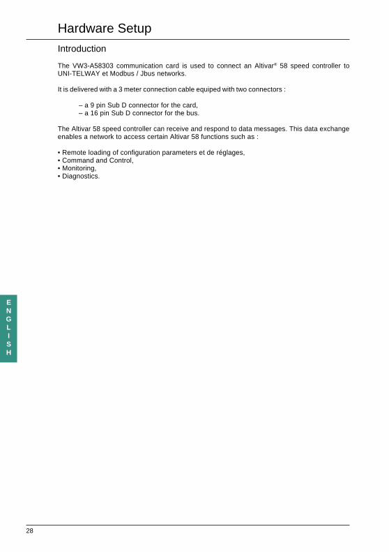
The VW3-A58303 communication card is used to connect an Altivar® 58 speed controller toUNI-TELWAY et Modbus / Jbus networks.
It is delivered with a 3 meter connection cable equiped with two connectors :
– a 9 pin Sub D connector for the card,– a 16 pin Sub D connector for the bus.
The Altivar 58 speed controller can receive and respond to data messages. This data exchangeenables a network to access certain Altivar 58 functions such as :
• Remote loading of configuration parameters et de réglages,• Command and Control,• Monitoring,• Diagnostics.

29
ENGLISH
Hardware Setup
Installing the Card, Address
Acceptance
Ensure that the card reference printed on the label is the same as that on the delivery notecorresponding to the purchase order.
Remove the option card from its packaging and check that it has not been damaged in transit.
Installing the card in the speed controller
Mounting Recommendations
Ensure that the speed controller is powered down.
To access the mounting slot for the option card, unlock cover 1 and open it.
Check that there is no power to the DC bus. Green LED 2 (POWER) must be off : wait 3 minutesafter powering down.
Open the flexible protection of the control card.
Mount the option card on the control card support by snapping it onto connector 3 and fix it bymeans of the three screws.
The cable is connected to the card by a 9 pin connector.
Put in place the label
The card is supplied with a self-adhesive label indicating the functions of thesignalling LEDs.Stick the label on the cover of the Altivar 58 below the existing label.
1
2
3
0
1
RUNERR
FAULT
POWER z

30
ENGLISH
1
0
1
0
1 2 3 4 5 876
1
0
1
0
1 2 3 4 5 876
2
3
1
10
1
8
Configuration switches
Signalling LEDs
Address switches
Connector
Hardware Setup
Card layout :
Coding the speed controller address :
An Altivar 58 is identified on the bus by its address, coded from 0 to 31.
The address corresponds to the binary number given by setting the 8 switches 1 on the card to1 or 0 (in fact only the switches 3 to 7 are used for the address).
Caution : the least significant bits are on the right.
Examples :
address 2
address 5
Setting all switches to 0 gives the address 0.
Signalling LED :
The UNI-TELWAY, Modbus/Jbus card has 2 lamps 2 whose function is detailled in the diagnosticchapter.
Configuration switches :
The card has two switches 3 for the protocol configuration.
• UNI-TELWAY protocol
• Modbus/Jbus protocol

31
ENGLISH
0V
PG
0V
D(B)
D(A)R
E
15
A'
B'
A
B
14
7
PG*
RX
0V
RXD+
RXD-
TXD+
TXD-
Zt
R
E
8
23
14
7
515
RD (B)
RD (A)
D (B)
D (A)E
5V
5V
4,7 kΩ
4,7 kΩ
100 kΩ
100 kΩ
OV
0V
0V0V
&
&RX
TX
1
2
3
4
5
6
7
815
14
13
12
11
10
9
1 nF
120Ω
Seen from externalcontact side
enabletrans-mission
SUB-D connector (15-pin) Automated system
ReceptionTransmission
Reception
Zt line terminatorrecommended atboth ends of the line
Transmission
Connection to the multidrop bus
SUB-D connector pinout
The RS 485 standard transmission interface is electrically isolated from the speed controller. It isavailable on a 15-pin SUB-D connector.
Connection to the standard RS 485 bus
Pins to use
* Connection of the shielding to both ends depends on installation constraints
Recommendations
• use a shielded cable with 2 pairs of twisted conductors,• connect the reference potentials to each other,• maximum length of the line : 1000 meters,• maximum length of a tap-link : 20 meters,• do not connect more than 28 stations on a bus,• cable routing : keep the bus away from the power cables (30 cm minimum), and make right-anglecrossovers if necessary; connect the cable shielding to the earth of each device,• fit a line terminator at both ends of the line.

32
ENGLISH
Connection to the multidrop bus
The following accessories are available for connecting equipment.
TSX-CSA… cables for bus sold in 100, 200 or 500 m lengths.
TSX-SCA62 subscriber connector
This passive unit comprises a printed circuit fitted with screw terminals for connecting 2 devicesto the bus. It includes an end of line terminator when the connector is located at the end. Theswitches on the connector must be set in the following way.
switch number switch position
2 OFF
3 OFF
5 OFF
the position of the other switches has no effect.
Example of connection to a UNI-TELWAY bus
TSX-SCM 21.6
TSX-CSAXXX
TSX-CSB015TSX-SCA62
ATV-58+
VW3-A58303
ATV-58+
VW3-A58303
ATV-58+
VW3-A58303

33
ENGLISH
Software Setup
Configuring Communication Functions
Initial power-up
When the Altivar 58 is connected to the supply the card is automatically recognised.The configuration menu 8-COMMUNICATION will appear on the display terminal(or programming terminal or PC software).
Configuration
Select the menu 8-COMMUNICATION for access to the configuration parameters of the card.This menu enables configuration of all the communication parameters.The first parameter is the network address of the drive, this parameter is only accessible onthe terminal, because it is configured by switches 3 to 7. The second parameter is the choiceof protocol.
Modification of the communication parameters is only possible when the motor has stopped.
Parameter Code Range Factory Commentssetting
Address AdrC 0 - 31 1 Drive address configurable byswitches 3 to 7 (reading only)
Protocol -Pro UNI-TELWAY -Modbus / RTU
Modbus / ASCII
Transmission -bdr 4.8 Value in Kbit/sspeed 9.6
19.2
Format (1) -For 7o1 - 7E1 For Modbus ASCII only7o2 - 7E2
8o1
8E1 - 8n1 For Modbus / ASCII and8n2 Modbus / RTU only
8o1 For all protocols
(1) Signification : 7 = 7 bits, 8 = 8 bits, o = uneven, E = even, n = without parity bit, 1-2 = numberof "stop" bits.

34
ENGLISH
Communication principle
Data structure
The adjustment, control, supervision and monitoring of the Altivar 58 are performed using data (orobjects) which are specific to the product.
The data essentially comprises :
WORDS (of 16 bits) : named Wi (i = word number) which are used for storage,either of complete digital values (- 32768 to + 32767), or of 16 independent logic states (in whichcase these words are termed registers).
Examples :
W401 = frequency reference (digital value),W483 = fault register (16 fault bits).
Notation : W483,2 designates the bit in row 2 of register W483.
Access to data
Some data can be accessed in both read and write : these are the bits and words corresponding toadjustments, references and commands. This data is used by the speed controller.
However, data produced by the speed controller can only be accessed in read : signalling or faultdata, etc. If written, they have no meaning and are rejected.
The variables of the ALTIVAR 58 and their control procedure are detailled in the manual"Internal communication variables".

35
ENGLISH
UNI-TELWAY requests
General
The exchange of data between computer systems, PLCs and other intelligent systems must beperformed using a common language.This language should be as simple as possible and understood by everyone involved. Nevertheless,it must be possible to check every exchange to ensure the integrity of the transfers. The variablesexchanged are therefore inserted in a frame which generally comprises the following :
Each protocol defines the presence, the format and the contents of the various groups of variableswhich surround the data zone.
This structuring makes it possible to define the start and the size of messages, if necessary thesystem to which the data is addressed, the type of function required, the variables themselves, acontrol parameter and an end code which validates the whole message.The form and content of this frame are different for each type of protocol.
List of requests
The following table describes the requests accepted by the Altivar 16 and their limits.Details of the coding of the requests are given in the UNI-TELWAY reference manual.
Request Code (hexa) Altivar 58
Identification H’0F’ YesProtocol version H’30' YesMirror H’FA’ YesRead error counters H’A2' YesReset counters H’A4' Yes
Read a word H’04' YesWrite a word H'14' Yes
Read objects H’36' 63 words max.Write objects H’37' 60 words max.
Specific H’F2' See later
Identification request - Request code H'OF'
Response given by AltivarResponse code = H'3F'Product type = H'18' for AltivarSub-type = H'58' Altivar 58Product version = H'XX' software version (eg : H'21' for V2.1)ASCII string* = Altivar size (eg : ATV-58U18N4)
* The first byte of an ASCII string always corresponds to the length of the string.
EndData CheckRequestAddressHeading
36
ENGLISH
UNI-TELWAY requests
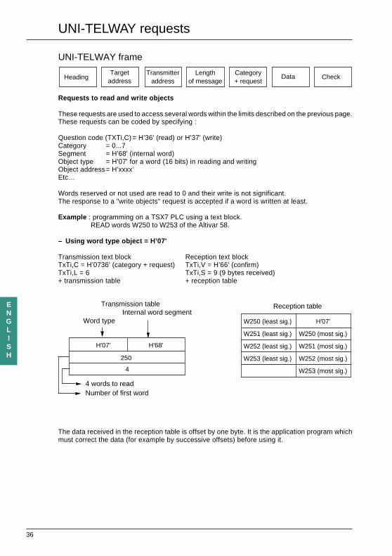
UNI-TELWAY frame
Requests to read and write objects
These requests are used to access several words within the limits described on the previous page.These requests can be coded by specifying :
Question code (TXTi,C) = H’36' (read) or H’37' (write)Category = 0...7Segment = H’68' (internal word)Object type = H’07' for a word (16 bits) in reading and writingObject address= H’xxxx’Etc…
Words reserved or not used are read to 0 and their write is not significant.The response to a "write objects" request is accepted if a word is written at least.
Example : programming on a TSX7 PLC using a text block. READ words W250 to W253 of the Altivar 58.
– Using word type object = H’07'
Transmission text block Reception text blockTxTi,C = H’0736' (category + request) TxTi,V = H’66' (confirm)TxTi,L = 6 TxTi,S = 9 (9 bytes received)+ transmission table + reception table
The data received in the reception table is offset by one byte. It is the application program whichmust correct the data (for example by successive offsets) before using it.
CheckTarget
addressTransmitter
addressLength
of messageCategory+ request
4 words to readNumber of first word
Transmission tableInternal word segment
Word type
4
250
H'07' H'68'
W250 (least sig.) H'07'
W251 (least sig.) W250 (most sig.)
W252 (least sig.) W251 (most sig.)
W253 (least sig.) W252 (most sig.)
W253 (most sig.)
Reception table
DataHeading

37
ENGLISH
UNI-TELWAY requests
Specific control request
This request is used to control the Altivar 58 and to obtain in return data essential for controllingthe speed controller.
Request format
Request code : byte = H'F2'Category : byte = 0...7Specific request code : byte = 0Reserved : byte = 0Command : word = CMDReference : word = FRHAcceleration : word = ACCDeceleration : word = DEC
Confirm format
Response code : byte = H'F2'Specific response code : byte = H’30'Reserved : byte = 0Reference : word = FRHStatus register : word = ETAFault register : word = FLTMotor current : word = LCR
Negative response
Response code : byte = H'FD'Cause : incorrect number of parameters

38
ENGLISH
Modbus / Jbus protocol
Modbus frames
Note : In the rest of this document Modbus and Jbus functions are grouped together under theheading Modbus.
Two transmission modes can be used, only one of them being used in a system.
RTU mode
The frame defined for the Modbus protocol has neither message heading bytes nor end of messagebytes. It is defined as follows :
The data is transmitted in binary code.CRC16 : cyclical redundancy check.The end of frame is detected on a silence of 3 characters or more.
ASCII mode
The frame is complete and is defined in the following way :
– heading = ":" (H’3A),– the data is coded in ASCII : each byte is divided into 2 four-bit bytes, each of which is coded by an ASCII character (0 to F),– LRC : longitudinal redundancy check,– end : "CR" "LF" (H’0D and H’0A).
Request CRC16Address
Address Request LRC End "CRLF"
Data
DataHeading

39
ENGLISH
Modbus / Jbus protocol
Principle
The Modbus protocol is a dialogue protocol which creates a hierarchical structure (a master andseveral slaves).The Modbus protocol enables the master to interrogate one or more intelligent slaves. A multidroplink connects the master and slaves.Two types of dialogue are possible between master and slaves :– the master talks to a slave and waits for a response,– the master talks to all the slaves without waiting for a response (broadcasting principle).The slaves are numbered from 1 to 255, and number 0 is reserved for broadcasting.
The master manages the exchange and only it can take theinitiative. The master repeats the question when there is anincorrect exchange, and declares the interrogatedslave absent if no response is received within a given timeenvelope. Only one device can transmit on the line at any time.No slave can send a message itself unless it is invited to do so.
Note
No lateral communication (ie. slave to slave) can be performed directly.The application software of the master must therefore be designed to interrogate a slave and sendback data received to another slave.
Master
Slave k
Slave j
Slave i

40
ENGLISH
Modbus / Jbus protocol
Accessible data
The Modbus protocol enables data (words) to be exchanged between a master and several slaves,and checks these exchanges.
Consequently, word areas are defined in each slave unit which will be read or written by the master.
An input object can only be read.An output object can be read or written.
Exchanges
The master, or supervision device, takes the initiative in exchanges. The master addresses a slaveby supplying it with four types of data :– the address of the slave,– the function required of the slave,– the data area (variable depending on the request),– the exchange check.
The link master waits for the response of the slave before transmitting the next message, thusavoiding any conflict on the line. Operation in half duplex is therefore authorized.
Use
rp
rog
ram
Master
Rec
eptio
nta
ble
Tra
nsm
issi
onta
ble
Slave i
Slave j
Outputwords
Inputwords
Slave k
Modbus addressing

41
ENGLISH
Modbus / Jbus protocol
Control and monitoring
All control of exchanges between two units which are communicating via asynchronous serial linknaturally includes exception messages when exchange faults occur. Various incorrect messagesmay be sent to a slave. In this event, the slave will tell the master that it does not understand, andthe master will decide whether or not to repeat the exchange.
The master has access to a certain amount of data which is stored and managed by the slave.The master can access this data using special function codes (diagnostic mode, read eventcounter, etc).
ATV 58
Master

42
ENGLISH
Modbus / Jbus protocol
Modbus functions
Modbus functions include :– main functions for exchanging data,– additional functions for exchange diagnostics.
The following table shows the functions which are managed by the ALTIVAR 58 communicationfunction, and specifies its limits.
The definition of the "read" and "write" functions are understood from the point of view of themaster.
Code Type of function D ALTIVAR 58
03 Read N output words 63 max04 Read N input words 63 max06 Write one output word D Yes08 Diagnostics (see details below) Yes11 Read event counter Yes16 Write N output words D 60 max
Functions marked «D» can be broadcast.The message transmitted by the master must specify slave number = 0.A response message is never returned.
Detailed information on functions
Code 03 : read N output words.This function is used to read output words (words which can be written and readin the slave by the master ).
Code 04 : read N input words.As above, but applies to input words (words which the master can only read).
Code 06 : write an output wordUsed to write a 16-bit output word (can only be accessed in write).

43
ENGLISH
Modbus / Jbus protocol
Diagnostic function code 08 is always accompanied by a sub-code.
Code 08/00 : echo.This function requests the interrogated slave to send back the whole message sentby the master.
Code 08/01 : channel reinitialization.This function is used to reinitialize communication of a slave and in particular tomake it leave listen only mode (LOM) by transmission of a data H'0000 ou H'FF00.
Code 08/03 : change of ASCII delimiter.In ASCII mode, messages are delimited by the line feed character (LF = H’0A).This function is used to change this character.
Code 08/04 : change to LOM mode.This function is used to force a slave into listen only mode (LOM).In this mode the slave does not process messages which are addressed to it, andonly transmits a response when the channel is reinitialized.
Code 08/0A : counter reset.This function resets to zero all the counters monitoring the exchanges of a slave.
Code 08/0B : number of correct messages seen on the line without CRC error orchecksum error.This function reads a 16-bit counter (incremented from 0 to H’FFFF)which totals the messages seen on the line and processed by the slave.
Code 08/0C : number of messages received with checksum error (reads a 16-bit counter).
Code 08/0D : number of exception responses.Reads a 16-bit counter which totals the number of exception messages transmittedto the master by a slave (following an incorrect frame).
Code 08/0E : number of messages addressed to the slave except for broadcasts.Reads a 16-bit counter which totals the number of all types of messages addressedto the slave.
Code 08/0F : number of broadcast messages received.Reads a 16-bit counter which totals the number of all types of messages addressedto the slave.
Code 08/10 : read number of NAQ responses. The value read is always 0.
Code 08/11 : read of number of responses from the slave that is not ready. The value readis always 0.
Code 08/12 : read the number of characters which are not processed (incorrect).
Code 11 : read event counter.– a status (always zero),– a counter which is incremented each time a correct message sent to the slaveis received (form and content) except for exception messages.
Code 16 : write N output words.This function enables the master to write output words to the slave (words whichcan be written or read).

44
ENGLISH
Modbus / Jbus protocol
Details of frames (RTU mode)
CRC16 calculation
The CRC16 is calculated based on all the bytes of the message by applying the following method.Initialize the CRC (16-bit register) to H’FFFF.Enter the first to the last byte of the message :
CRC X0R <byte> —> CRCEnter 8 times
Move the CRC one bit to the rightIf the output bit = 1, enter CRC X0R H’A001—> CRC
End enterEnd enterThe CRC obtained will be transmitted least significant byte first, then most significant.X0R = exclusive OR.
Read N words : function 3 or 4
Question
Slave 03 or 04 N° of 1st word Number of words CRC16n° MS LS MS LS
1 byte 1 byte 2 bytes 2 bytes 2 bytes
Réponse
Slave 03 or 04 Number of Value of Value of CRC16n° bytes read 1st word last word
MS LS MS LS1 byte 1 byte 1 byte 2 bytes 2 bytes 2 bytes
Example : read words W463 to W466 of slave 1
Question 01 03 01CF 0004 75CA
Response 01 03 08 xxxx xxxx CRC16
Value Valueof W463 of W466
Write an output word : function 6
Question
Slave 06 Word number Word value CRC16n° MS LS MS LS
1 byte 1 byte 2 bytes 2 bytes 2 bytes
Response
Slave 06 Word number Word value CRC16n° MS LS MS LS
1 byte 1 byte 2 bytes 2 bytes 2 bytes
Example : write value H'0315' = 789 in word W252of slave 1 ( ACC = 78,9s )
Question 01 06 00FC 0315 88C5and response
-------
----------------------

45
ENGLISH
Modbus / Jbus protocol
Diagnostic : function 8
Question and response
Slave 08 Sub-code Data CRC16n°
1 byte 1 byte 2 bytes 2 bytes 2 bytes
Sub-code Question data Response data Function executed
00 XX YY XX YY Echo01 00 00 00 00 Reinitialization03 XX 00 XX 00 XX = new delimiter04 00 00 No response Change to LOM mode0A 00 00 00 00 Reset counters to 00B 00 00 XX YY XXYY = counter value0C 00 00 XX YY XXYY = counter value0D 00 00 XX YY XXYY = counter value0E 00 00 XX YY XXYY = counter value
Read event counter : function 11 ( H'0B' )
Question
Slave 0B CRC16n°
1 byte 1 byte 2 bytes
Response
Slave 0B 00 00 Counter value CRC16n° MS LS
1 byte 1 byte 2 bytes 2 bytes 2 bytes
Write N output words : function 16 (H'10' )
Question
Slave 10 N° of 1st word Number Number Value of 1st word CRC16n° MS LS of words of bytes MS LS
1 byte 1 byte 2 bytes 2 bytes 1 byte 2 bytes 2 bytes
Response
Slave 10 N° of 1st word Number of words CRC16n° MS LS MS LS
1 byte 1 byte 2 bytes 2 bytes 2 bytes
Example : write values 6 and 500 in words W400 and W401 of slave 2.
Question 02 10 0190 0002 04 0006 01F4 1801
Response 02 10 0190 0002 402A
----

46
ENGLISH
Modbus / Jbus protocol
Exception responses
An exception response is given by a slave when it is unable to perform the request which isaddressed to it.
Format of an exception response :
Slave Response Error CRC16n° code code
1 byte 1 byte 1 byte 2 bytes
Response code : function code of the request + H’80 (the most significant bit is set to 1).
Error code : 1 = the function requested is not recognized by the slave.2 = the bit and word numbers (addresses) indicated in the request do not exist in
the slave.3 = the bit and word values indicated in the request are not permissible in the slave.4 = the slave has started to execute the request, but cannot continue to execute
it completely.

47
ENGLISH
Modbus / Jbus protocol
ASCII mode
In this mode, the Modbus frame has the following structure :
• Slave n° Function Data LRC CR LF• code MS LS
Data identical to RTU mode,but coded differently
Delimiters : ":" = H’3A’, CR = H’0D’, LF = H’0A’.
Data : the data field is analogous to the RTU frames, but coded in ASCII characters. Each byte isdivided into 2 four-bit bytes, each of which is coded by its ASCII equivalent.
Example : the byte containing the slave number 06 will be coded by 2 ASCII characters "0" and "6", ie. by H’30' and H’36'.
LRC : modulo 256 hexadecimal sum of the contents of the frame (without the delimiters) beforeASCII coding, 2's complement.The byte obtained is then coded in the form of 2 ASCII characters as above.
Example : write value 10 in word W252 of slave 2
Question and response
ASCII
3A 30 32 30 36 30304643 30303041 4632 0D 0A
Hexadecimal
: 0 2 0 6 0 0 F C 0 0 0 A F 2 CR LF
LRC calculation
Sum of the bytes in the frame :H'02' + H'06' + H'00' + H'FC' + H'00' + H'0A' = H'10E' = 270
Modulo sum 256 : H'0E' = 14
Modulo sum 256, 2's complement :H'100' - H'0E' = 256 - 14 = 242 = H'F2'
---------------------

48
ENGLISH
Diagnostics
Fault
For an explanation of the codes consult the manual «Internal communication variables».
Additional diagnostics
Check the state of the 2 lamps RUN and ERR mounted on the card and visible through the cover ofthe Altivar :
RUN : green lampERR : red lamp
Lamp status :0 = off 1/2 = slow flashing (500 ms)1 = on 1/10 = fast flashing (100 ms)
RUN ERRlamp lamp Probable cause Corrective actiongreen red
1 0 Normal operation, bus and OKstarter present
0 0 Not operating Check supply
0 1 Communication fault Check the communication bus andon the bus the connectors. Also check the switches
0 1/10 * Character error Check communication configuration
1/10 0 Communication not configured Configure communication
1/2 0 Communication fault between Check 30 pin connector between Altivarthe Altivar and communication and cardcard
* This display flashes for 6 x 100 ms if an incorrect character has been received. This short flashingis repeated after a period of five seconds if an incorrect character is received. This only occurswhen the communication card is set for communication fault (no message received for 10 s for buscommunication or 1 s for ASCII protocol).
If the card never changes to normal operation, this display indicates that the wiring is definitelycorrect but that the configuration is not suitable (speed or format).
RUNERR
FAULT
POWER z

49
ENGLISH

VVDED397054 W9 1598007 01 11 A01
85593 1998-05


![Altivar 18 Telemecanique - Elmatik speed drives Altivar 18 User Guide...Altivar 18 Telemecanique Jmdh\h^kl\h Ij_h[jZah\Zl_eb qZklhlu ih wdkiemZlZpbb ^ey Zkbgojhgguo ^\b]Zl_e_c. 6 1](https://img.dokumen.tips/doc/110x75/5ec0a3b09d489557bf438e23/altivar-18-telemecanique-speed-drives-altivar-18-user-guide-altivar-18-telemecanique.jpg)