Embed Size (px)
Citation preview

InstructorDerek Jackson CID+Product Expert
AltiumLive 2018University Day

Altium Designer xSignals
How to Route and tune high speed topologies with xSignals
A look at xSignals in Altium Designer.
Altium Designer xSignals
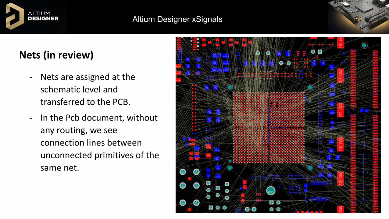
Nets (in review)
- Nets are assigned at the schematic level and transferred to the PCB.
- In the Pcb document, without any routing, we see connection lines between unconnected primitives of the same net.

Altium Designer xSignals
Nets (in review)In the PCB Panel, under the Nets section, we can see net information , including:
- Net Name- Routed Net Length: The routed track length
that does not sort out overlapping segments.
- Signal Length: A calculated distance that provids an accurate calculation length of routing between two pad objects, excluding track overlaps in the total, and handles fills, via lengths.
For more than two connected nodes, this will display n/a.
Altium Designer xSignals
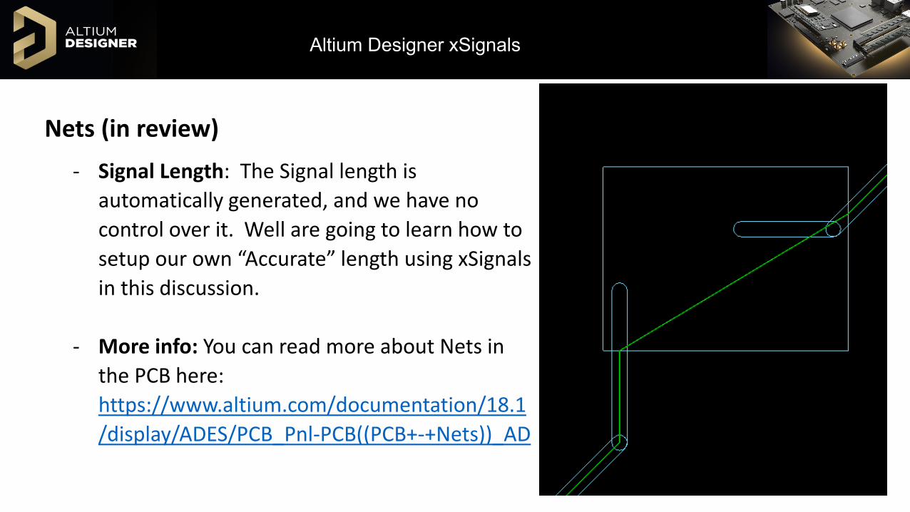
Nets (in review)- Signal Length: The Signal length is
automatically generated, and we have no control over it. Well are going to learn how to setup our own “Accurate” length using xSignals in this discussion.
- More info: You can read more about Nets in the PCB here: https://www.altium.com/documentation/18.1/display/ADES/PCB_Pnl-PCB((PCB+-+Nets))_AD
Altium Designer xSignals
Length Tuning:- For signals that need to travel from a source component and arrive at different
destinations at the same time will need to have their routed tracks the same length. This is done using various Length Matching techniques.
- More info: https://www.altium.com/documentation/18.1/display/ADES/((Length+Tuning))_AD

Altium Designer xSignals
Length Matching RulesLength Matching Rule:
- In Altium Designer, a Matched Length Rule can be defined which defines the allowable range of the track lengths (Design » Rules » High Speed » Matched Lengths) for the specified nets.

Altium Designer xSignals
Length Matching RulesThe rule interprets lengths from all the routed nets referenced by the rule as follows:
Matched Net Length’s Min Limit = Longest Net – Rule ToleranceMatched Net Length’s Max Limit = Longest Net
(constrained by the length rule)
Valid Range = Highest Min Limit to Lowest Max Limit (most stringent combination of Length and Matched Length rules)Target Length = Lowest Max Limit
Altium Designer xSignals
Matched Length Rule:“Group Matched Lengths”: Set the target for all nets targeted by the rule, looking at the longest net length to set the maximum.
“Within Differential Pair Length”: Matched length is between the legs of a differential pair.Tolerance: Provides the amount of variance from the total routed length by up to this amount. The target length range is defined by the equation:
(Longest Length - Tolerance) ≤ Current Length ≤ Longest Length
https://www.altium.com/documentation/18.1/display/ADES/PCB_Dlg-MatchedNetLengthsRule_Frame((Matched+Lengths))_AD
Altium Designer xSignals
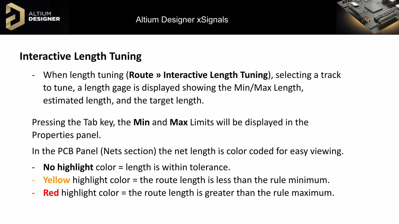
Interactive Length Tuning- When length tuning (Route » Interactive Length Tuning), selecting a track
to tune, a length gage is displayed showing the Min/Max Length, estimated length, and the target length.
Pressing the Tab key, the Min and Max Limits will be displayed in the Properties panel.
In the PCB Panel (Nets section) the net length is color coded for easy viewing.
- No highlight color = length is within tolerance.- Yellow highlight color = the route length is less than the rule minimum.- Red highlight color = the route length is greater than the rule maximum.

Altium Designer xSignals
Interactive Length Tuning
Altium Designer xSignals
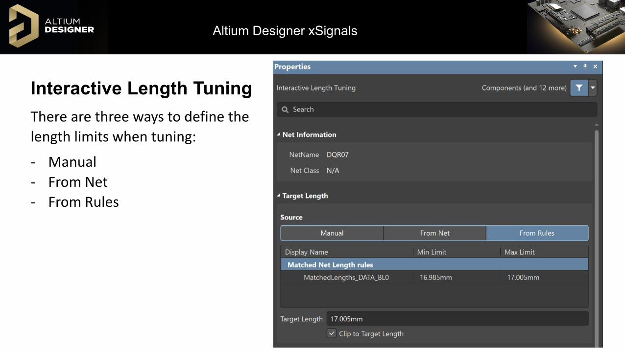
Interactive Length TuningThere are three ways to define the length limits when tuning:
- Manual- From Net- From Rules

Altium Designer xSignals
Interactive Length Tuning- During routing, display the length gage by
pressing Shift+G- If no Length Matching rule applies, the
min/max will display 0/Current length or 0/0.
- During Length Tuning, the Min, Max, and target lengths are shown.
A very old Length tuning video, but great information: http://videos.altium.com/trainingcenter/player.html?ep=1047
Altium Designer xSignals
Accordions:For length tuning, accordions are the length of track added to the route to increase the length.
- Style: Mitered Lines/Arcs or Rounded. (Space Bar to cycle)
- Interactive Routing: When routing, accordions can be added by pressing Shift+A.
- Tab: pressing Tab during a tuning / Routing command, will display its properties in the Pattern section, allowing adjustments. amplitude, gap, and miter. Shortcuts are listed in the Panel. During the command, you can press the ~ to get a list of shortcuts.

Altium Designer xSignals
Accordion Object:For length tuned tracks, an accordion control object gets added with the length tuning. is control appears as a bounding box around the tuned section. Modifying an accordion:
- Double-clicking: Select an accordion to edit its properties in the Properties Panel.
- Dragging: Dragging the sides or vertices of the accordion object will adjust the added tuning and scale accordingly.
Currently, accordion control objects are not added when tuning Differential Pairs: (https://bugcrunch.live.altium.com/#Idea/8016)
More Info: https://www.altium.com/documentation/18.1/display/ADES/PCB_Obj-Accordion((Accordion))_AD
Altium Designer xSignals
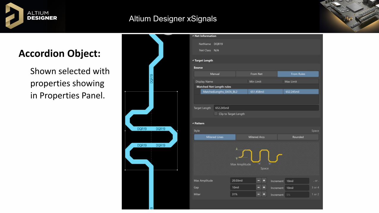
Accordion Object:Shown selected with properties showing in Properties Panel.

Altium Designer xSignals
Accordions:The Accordion style can be 90, mitered with lines or serpentine.
- When using miters, the Space is the inner gap, and the miter is represented as a percentage of the space length value.
Altium Designer xSignals
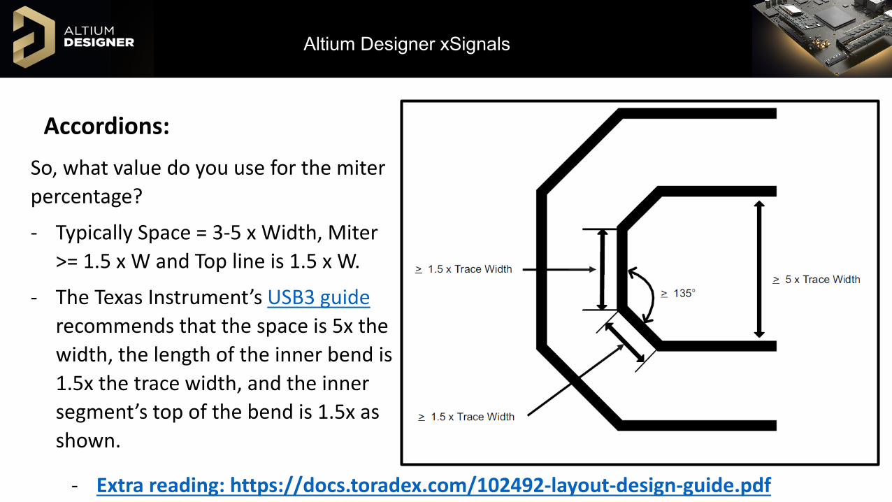
Accordions:So, what value do you use for the miter percentage?
- Typically Space = 3-5 x Width, Miter >= 1.5 x W and Top line is 1.5 x W.
- The Texas Instrument’s USB3 guide recommends that the space is 5x the width, the length of the inner bend is 1.5x the trace width, and the inner segment’s top of the bend is 1.5x as shown.
- Extra reading: https://docs.toradex.com/102492-layout-design-guide.pdf

Altium Designer xSignals
xSignals:An xSignal is defined as a path for a signal to travel between a source and destination (pin pairs), and can include termination components as well as branches (Balanced-T or Fly-By).
- Virtual Net: Similar to the Signal Length calculation, but differs that xSignals can be created and used for accurate route measurements.
- Creation: xSignals can be created with or without routing between the selected pin pairs.- xSignals can be created from selected Pads, components or the xSignal
wizard.- xSignals will follow the routing topology set for the selected nets.

Altium Designer xSignals
xSignal Creation:Accessing the xSignals menu (Design » xSignals), depending on what is selected will affect available menu options…
- From the Menu:» Run xSignals Wizard » Create xSignals
- With Pads selected (from menu or right-clicking on a selected pad):» Create xSignal from selected pins
- With Components selected:» Create xSignals between components» Create xSignals from connected Nets
More information: https://www.altium.com/documentation/18.1/display/ADES/((Defining+High+Speed+Signal+Paths+with+xSignals))_AD

Altium Designer xSignals
xSignal Panel:There are three regions in the xSignal section of the PCB panel: - xSignal Classes- xSignals belonging to the selected class- Primitives in the xSignal (pads, tracks, arcs, and vias)
In the xSignal section of the PCB panel, we also see Signal Length, Routed Length, Unrouted Length, and Total Pin/Package length.
Similarly to the Nets section, for Length Matching rules we will see the nets lengths change color based if they are shorter, longer, or in the target length range as we saw earlier.

Altium Designer xSignals
xSignal Panel:
Shown, for the selected Net signal, all primities are sown. Clicking the Show nodes only will only display connected Pads.
Altium Designer xSignals
Pin-Package Delays:- To account for the length added from routing inside the chip package, most manufacturers will supply a pin package length.
- Adding a pin package length to your footprint will add the total package length to the calculated signal length when a single track connects to it (flyby topologies are excluded).
- The length can be define at the schematic level (recommended), or directly in the PCB.
- The Intel Memory Interface Handbook recommends including package delays for speeds greater than 800MHz.
Extra reading Pin Pairs:https://www.altium.com/documentation/18.0/display/ADES/PCB_Cmd-ManagePinPairs((ManagePinPairs))_AD
Altium Designer xSignals
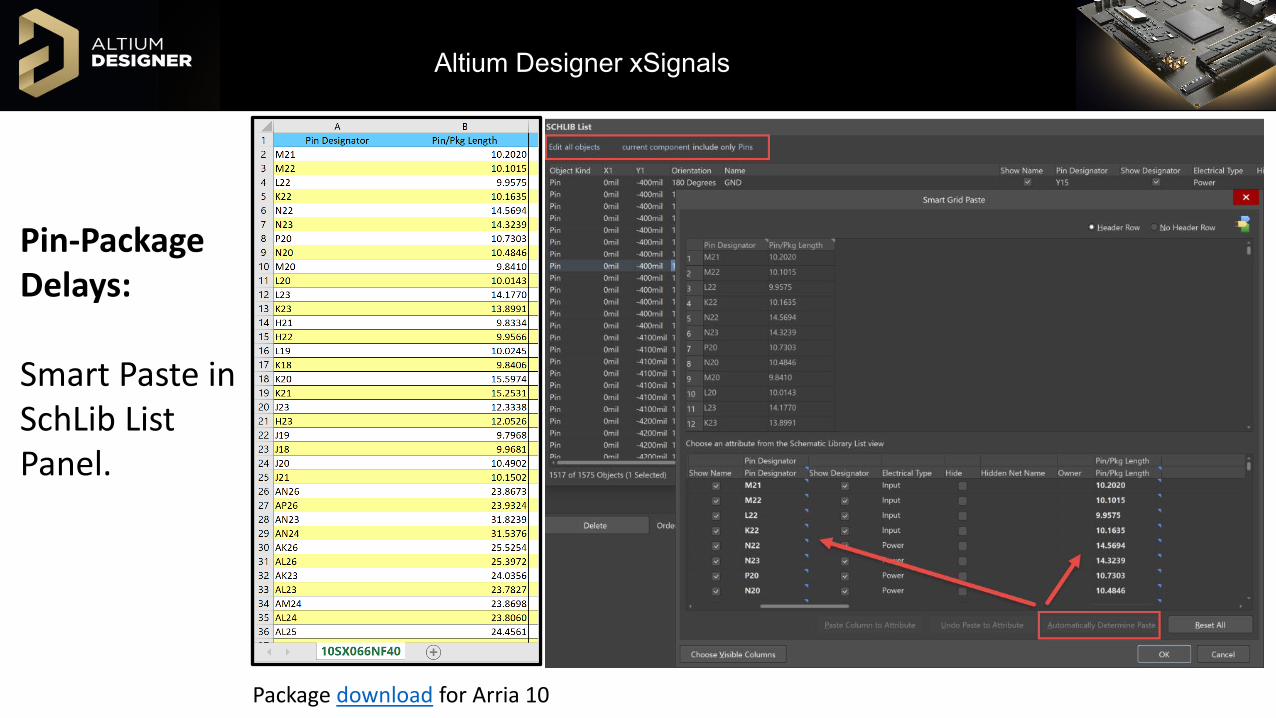
Pin-Package Delays:
Smart Paste in SchLib List Panel.
Package download for Arria 10
Altium Designer xSignals
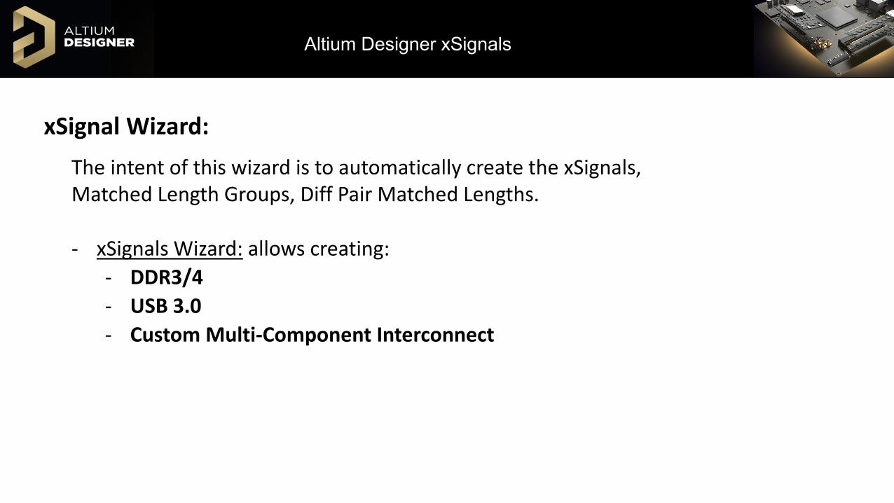
xSignal Wizard:The intent of this wizard is to automatically create the xSignals, Matched Length Groups, Diff Pair Matched Lengths.
- xSignals Wizard: allows creating:- DDR3/4- USB 3.0- Custom Multi-Component Interconnect

Altium Designer xSignals
xSignal Wizard:DDR3
- Supports Flyby or Balanced T.- For Balanced T topology, at
the separation point, signals must use a special single pad component to define the split point.
- Do not use # in net names as this represents the bank number when defining.
Altium Designer xSignals
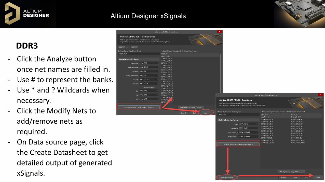
DDR3- Click the Analyze button
once net names are filled in.- Use # to represent the banks.- Use * and ? Wildcards when
necessary.- Click the Modify Nets to
add/remove nets as required.
- On Data source page, click the Create Datasheet to get detailed output of generated xSignals.

Altium Designer xSignals
xSignal Wizard:
USB 3.0
- The USB Wizard will add length matching for the diff pairs.
- Allows selection of multiple connectors
- TI USB 3 reference: http://www.ti.com/lit/an/spraar7g/spraar7g.pdf
Altium Designer xSignals
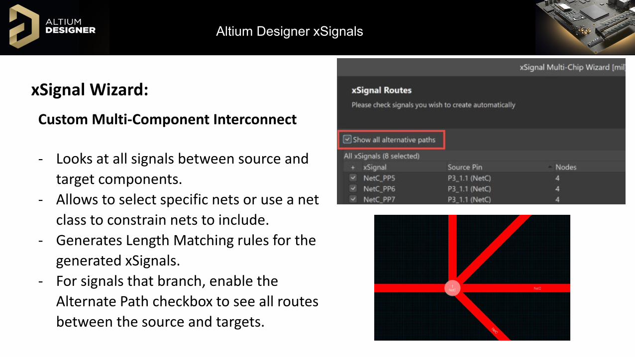
xSignal Wizard:Custom Multi-Component Interconnect
- Looks at all signals between source and target components.
- Allows to select specific nets or use a net class to constrain nets to include.
- Generates Length Matching rules for the generated xSignals.
- For signals that branch, enable the Alternate Path checkbox to see all routes between the source and targets.
Altium Designer xSignals
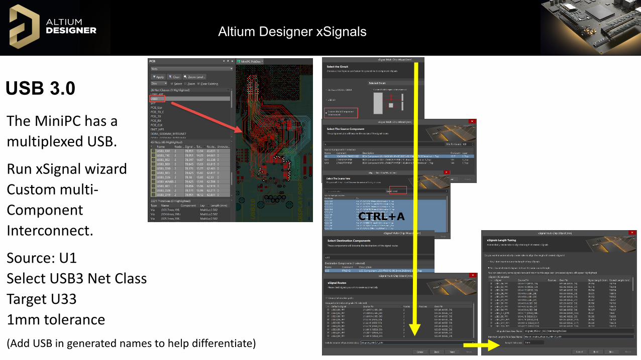
USB 3.0The MiniPC has a multiplexed USB.
Run xSignal wizard Custom multi-Component Interconnect.
Source: U1 Select USB3 Net ClassTarget U331mm tolerance(Add USB in generated names to help differentiate)

Altium Designer xSignals
AltiumLive 2018DEMO

Altium Designer xSignals
AltiumLive 2018Questions?