Embed Size (px)
Citation preview

1
NASA Glenn Research Center
ALTITUDE WIND TUNNEL
AIR DRYER SYSTEM DESCRIPTION
Current Buildings 18‐1 and 18‐2
April 2012
Bob Arrighi NASA Glenn History Program Wyle Information Services
2
Building 18‐2: The Natural Gas Compressor Building Building 18‐2 (the Natural Gas Compressor Building) was originally constructed as part of the Altitude Wind Tunnel (AWT) complex. The structure was originally named the Air Dryer Building. The Air Dryer Building was a component of the AWT’s make‐up air system. The makeup air system was designed to replenish the air inside the AWT that was removed by the exhaust scoop. The tunnel’s air stream was conditioned to simulate the atmosphere at high altitudes. The Air Dryer Building removed condensation and cooled the air to prevent shocks to the airflow as the new air entered the tunnel. The facility, located externally outside the tunnel’s southwest corner, consisted of the air dryer tank and two sets of cooling coils. The approximately 28‐ft‐8‐in.‐diameter tank was enclosed in a two‐story brick building with cooling coils located before and after. It was connected in front and behind by large ducts to the Primary Coils Building and the Secondary Coils Building. The Primary Coils Building was 21 ft 3.5 in. wide and 25.25 in. long. The Secondary Coils Building was 24 ft 8 in. wide and 33 ft 8 in. long.1
Figure 1—Original air dryer setup with the secondary coils (left), dryer tank (center), and primary coils (right) (viewed from the west), 1945 (C–1945–12004, NASA Glenn).
3
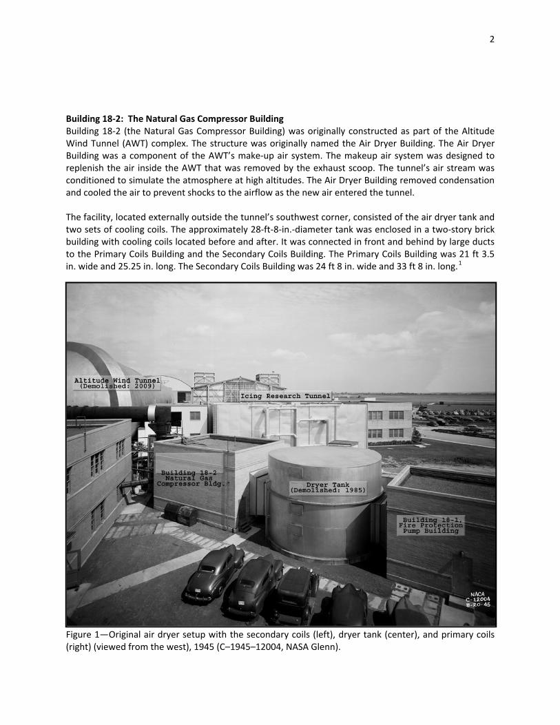
Ambient air entered the Primary Coils Building from the south and passed through a damper, a bank of filters, the two cooling coils, an eliminator, and another damper, which reduced its temperature to about 40 °F.2 The air then entered the air dryer tank where four flat beds of activated alumina layered on top of one another absorbed moisture to a dew point of –70 °F.3 The air then entered the Secondary Coils Building north of the dryer; this cooled the air to the desired tunnel temperature of approximately –47 °F. The dryer’s cooling coils were cooled by 12 reciprocating York compressors located in the nearby Refrigeration Building. A large duct permitted airflow between the air dryer and the primary coils during cooling and activation.4 The alumina had to be reactivated between runs by running steam‐heated air through the dryer in the reverse direction. It required approximately 5 hours to remove all the moisture from the alumina. The beds were then cooled by running chilled air through the dryer.5 The resulting cool, dry air was pumped to both the AWT and the adjacent Small Supersonic Wind Tunnels Building through a 48‐in.‐diameter pipe. The conditioned air was introduced into the AWT through pressure‐sensitive valves in two portals in the western tunnel wall. The southern 48‐in. portal allowed some of the air in, but a portion was redirected through a pipe that narrowed from 60 to 36 in. in diameter and was tied into the Refrigeration Building.6 This uncontaminated air was then pumped from the refrigeration system into the tunnel upstream from the test section.7
Figure 2—Air Dryer Building after a new dryer tank and primary coils were added on top (viewed from the northwest), 1955 (C–1955–39057, NASA Glenn).

4
During a 1948 upgrade, a new air tank was built on top of the existing tank and new cooling coils were installed on top of the existing Primary Coils Building, replacing the function of the original equipment. The original duct was redirected to this upper chamber and a U‐shaped reactivation duct connected the north side of this new chamber to the Primary Coils Building.8 Based on aerial photographs, it appears that the makeup air line directed to the Refrigeration Building was removed in August 1985.9 The air dryer tank was demolished sometime prior to 1990. The Primary Coils Building (Bldg. 18–1) became the Fire Pump Building. The Secondary Coils Building (Bldg. 18–2) became the Gas Compressor Building.
Figure 3—Plan and elevation drawing for the Air Dryer Building addition, 1948 (CD–1679, NASA Glenn).

5
Figure 4—Elevation drawings of the Air Dryer Building, 1948 (CD–1680–01, NASA Glenn).
6
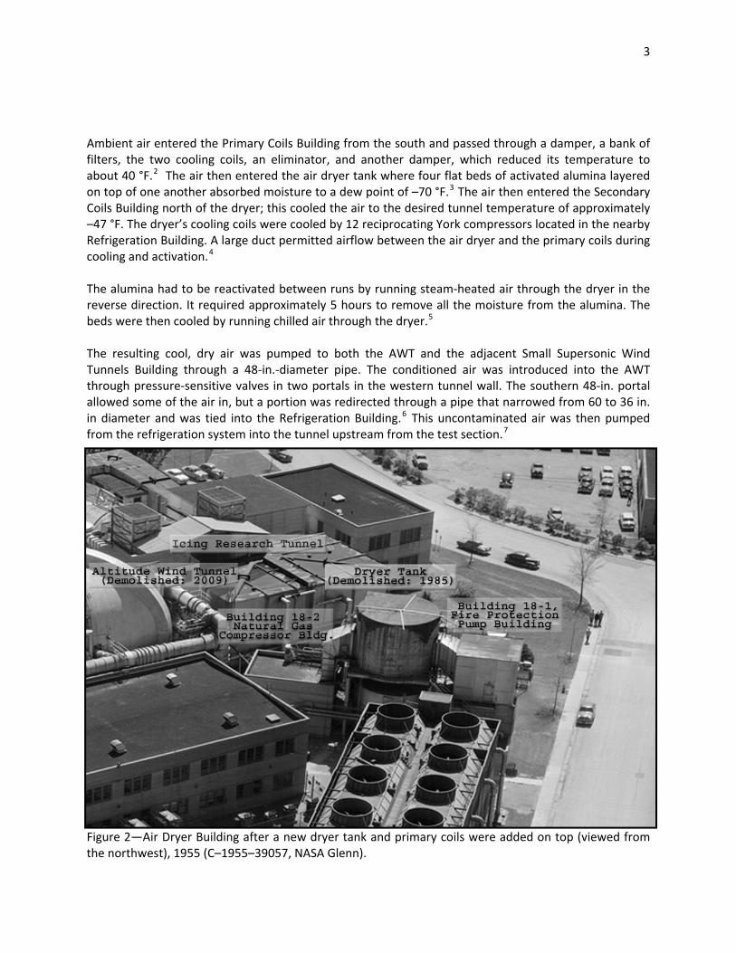
Figure 5—Air Dryer Building showing air pipes feeding the AWT (left) and the Small Supersonic Tunnels (right) (viewed from the southwest), 1945 (C–1945–13046, NASA Glenn).

7
Building 18‐2 in November 2011 Prior to Demolition
Figure 6— Former Natural Gas Compressor Building (NASA C‐2011‐04754)

8
Figure 7—Buildings 18‐1 and 18‐2 with the Icing Research Tunnel Cooling Tower in the background (NASA C‐2011‐04756)
Figure 8— Former Natural Gas Compressor Building (NASA C‐2011‐04757)
9
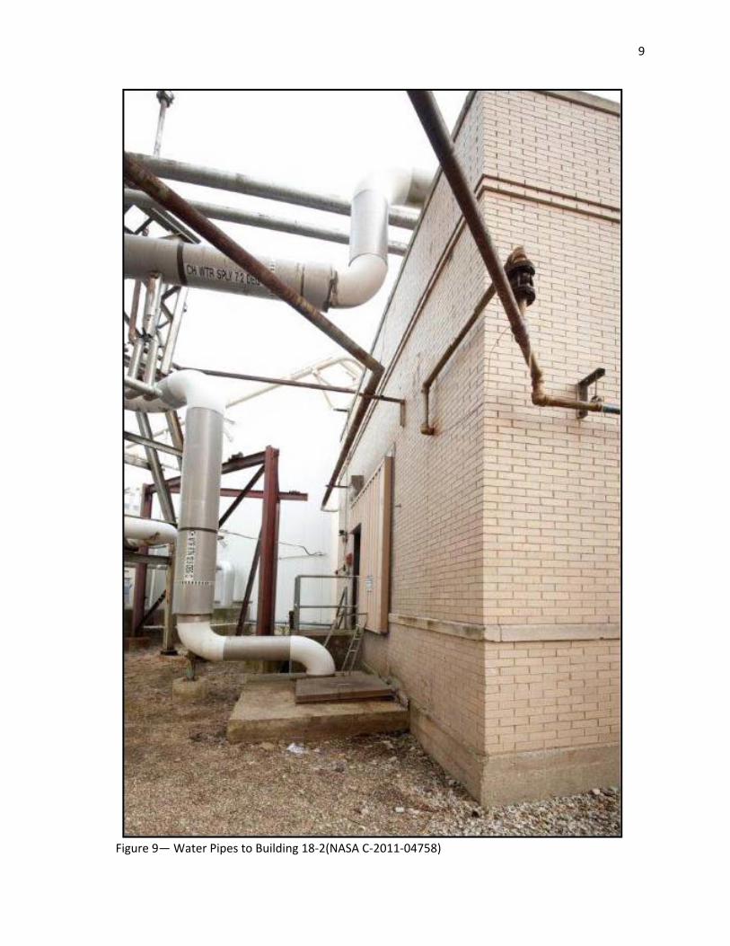
Figure 9— Water Pipes to Building 18‐2(NASA C‐2011‐04758)

10
Figure 10— Natural Gas Accumulators inside Building 18‐2 (NASA C‐2011‐04759)
Figure 11— Natural Gas Accumulators inside Building 18‐2 (NASA C‐2011‐04763)

11
Figure 12— Natural Gas Compressor Drive Motor inside Building 18‐2 (NASA C‐2011‐04760)
Figure 13— Natural Gas Compressor Motor and Gearbox inside Building 18‐2 (NASA C‐2011‐04767)

12
Figure 14— Natural Gas Compressor inside Building 18‐2 (NASA C‐2011‐04761)
Figure 15— Accumulators inside Building 18‐2 (NASA C‐2011‐04765)
13
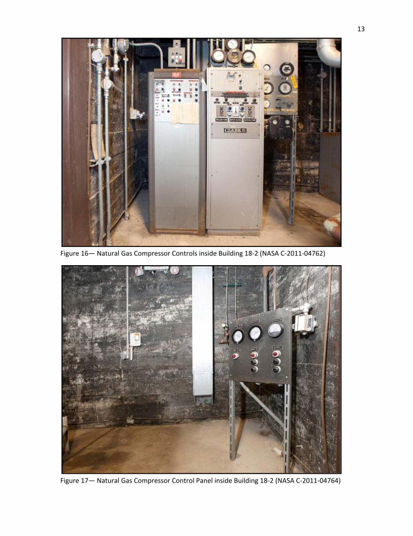
Figure 16— Natural Gas Compressor Controls inside Building 18‐2 (NASA C‐2011‐04762)
Figure 17— Natural Gas Compressor Control Panel inside Building 18‐2 (NASA C‐2011‐04764)

14
1 Air Dryer, Primary and Secondary Coils Building Plans. EE–510, NACA AERL drawing, Jan. 1943. 2 Air Dryer No.1, Tank Reactivation Duct and Primary System. CD–104827, NACA Lewis Flight Propulsion Laboratory drawing, Oct. 1948. 3 Whitney, Ernest G.: Lecture 22—Altitude Wind Tunnel at AERL. June 23, 1943, p. 2 (NASA Glenn History Collection, Altitude Wind Tunnel Collection). 4 AWT Facilities Addition Air Dryer Building Plan and Elevation. CD–1679, NACA AERL drawing, May 1948. 5 AWT Facilities Addition Air Dryer Building Plan and Elevation. CD–1679, NACA AERL drawing, May 1948. 6 Whitney, Ernest G.: Lecture 22—Altitude Wind Tunnel at AERL. June 23, 1943, p. 2 (NASA Glenn History Collection, Altitude Wind Tunnel Collection). 7 Victory, John: New NACA Wind Tunnels. Aero Digest, Aug. 1, 1944. 8 AWT Facilities Addition Air Dryer Building Plan and Elevation. CD–1679, NACA AERL drawing, May 1948. 9 150 PSIG Combustion Air Lines Extension to AWT and IRT, Demolition Plan and Reaction. CF–1590, NASA Lewis Research Center drawing, Aug. 28, 1985.