Embed Size (px)
Citation preview

AltiMAX! G4Universal Rocketry Altimeter
Translation of the originaloperating instructions
ENGLISH
Rocketronics

AltiMAX G4 Manual
ALTIMAX G4 2 © 2021 Rocketronics.com
Table of Contents: Intended use ................................................................................................................................... 4 Overview ......................................................................................................................................... 6 Operating principle .......................................................................................................................... 7 Data storage .................................................................................................................................... 8 Apogee point detection .................................................................................................................... 8 Technical data ............................................................................................................................... 10 Function scheme ........................................................................................................................... 11
Air holes .................................................................................................................................... 13 Electrical connection ..................................................................................................................... 14 Power supply ................................................................................................................................. 15
Magswitch ................................................................................................................................. 15 Batteries .................................................................................................................................... 15
Ignition outputs .............................................................................................................................. 16 ARM connector .......................................................................................................................... 16 FETCHECK ............................................................................................................................... 16 BROWNOUTPROTECT ............................................................................................................ 16 External ignition power supply ................................................................................................... 17 LEDs for testing the outputs ...................................................................................................... 17 Vacuum cleaner test .................................................................................................................. 17 Automatic igniter test ................................................................................................................. 18
Servo Connection .......................................................................................................................... 19 Connection G4 Connector ............................................................................................................. 20 Connection LCD terminal .............................................................................................................. 22 Connection OLED display ............................................................................................................. 22 Connection AUX I/O ...................................................................................................................... 23 Launch procedure ......................................................................................................................... 25 Settings ......................................................................................................................................... 28
General settings ........................................................................................................................ 28 Servo + AUX I/O settings ........................................................................................................... 28
Altimax event system..................................................................................................................... 30 Examples:.................................................................................................................................. 32
Software update ............................................................................................................................ 34 Using the PC software ................................................................................................................... 35
Installation ................................................................................................................................. 35 Updates ..................................................................................................................................... 35 Features of the software ............................................................................................................ 35 User interface ............................................................................................................................ 35 Menu and toolbar....................................................................................................................... 35 Setting the COM port ................................................................................................................. 37 Establish serial connection ........................................................................................................ 38 Flight data retrieval .................................................................................................................... 40 Flight data graphic ..................................................................................................................... 41 Selection of the data curves to be displayed .............................................................................. 42 Evaluate on-board voltages ....................................................................................................... 42 General settings ........................................................................................................................ 44 Servo+AUX I/O settings ............................................................................................................. 46 Setting AUX I/Os ....................................................................................................................... 47 Tests ......................................................................................................................................... 49 Firmware update........................................................................................................................ 50 Save data .................................................................................................................................. 52 Open data.................................................................................................................................. 52 Export data ................................................................................................................................ 52
Using the LCD terminal ................................................................................................................. 53

AltiMAX G4 Manual
ALTIMAX G4 3 © 2021 Rocketronics.com
Terminal menu .......................................................................................................................... 54 The menu: ............................................................................................................................. 57 Event menu of the LCD terminal ............................................................................................ 62
Disclaimer and warranty ................................................................................................................ 70 Contact .......................................................................................................................................... 71 Disposal ........................................................................................................................................ 71
Visit our website!
At www.rocketronics.de you will find current manuals, softwareupdates and 3D-Data for your altimaxgibt es aktuelle Handbücher,
www.rocketronics.de

AltiMAX G4 Manual
ALTIMAX G4 4 © 2021 Rocketronics.com
Intended use The Altimax G4 altimeter is used to record measured values (air pressure, acceleration, voltages) during the flight of a rocket. The maximum flight altitude can be 30,000 m. From these measured values, altitude, velocity and acceleration are calculated and, based on these values, times for activation of ignition outputs or servo positions are determined and events are generated. The user can link certain events to the triggering of timers, ignition outputs or servos and thus activate outputs or servos at very specific events. The three ignition outputs are used to switch current to igniters in order to trigger them. The igniters usually ignite ejection charges to eject parachutes for recovery. The measured values can be transferred to a PC, a software for Windows is available. Any use is expressly at your own risk and is only permitted in civil applications.
Fly high, but safe!

AltiMAX G4 Manual
ALTIMAX G4 5 © 2021 Rocketronics.com
Terms System startup The time at which the altimeter is switched on Ready for launch The point in time when the altimeter has calibrated the sensors and is waiting for a launch of the rocket. From this point on, all outputs are armed. An ascent above 24m or an acceleration above 3G for more than 0.1 seconds will result in a launch detection. Assembly time After switching on, there is a one-time output of the igniter states and the output of the last reached flight altitude by beeps. This is followed by a waiting time, which lasts as long as the assembly time is set. This pause is used to perform necessary work on the rocket before the electronics switch to the launch readiness mode. During this time everything is allowed, but after this time the rocket must be in launch position if a launch is to take place! Mach Delay Time to wait during ascent before reacting to pressure changes. For supersonic flights, this time must be adjusted, otherwise false triggering may occur due to pressure fluctuations in the area of the passage. Height descent At this altitude the main chute is normally ejected. At this altitude Pyro 2 is usually ignited, servo 2 is triggered. For large rockets this altitude should be at least 150 m, for small ones you can go down to 80 m. Please always take into account how long a parachute needs to fully unfold! Adjustable are 29 to 500 m Apogee The highest point of the flight path, at this point a parachute should ideally be ejected, that the speed of the rocket is lowest there. Most often this is done with Pyro 1. Two-stage recovery Two-stage recovery ensures short distances: A high-flying rocket ejects a small parachute at the apogee point. This ensures a controlled fall of the rocket, but at high speed. Only shortly above the earth, usually in 100-150 m , the actual recovery parachute is ejected, this slows down the rocket to 4-6 m/s and allows an intact recovery. The process ensures that the rocket is not blown so far by the wind, which is safer than uncontrolled drifting to great distances. The main parachute is the so-called MAIN CHUTE, the drogue parachute is the DROGUE CHUTE.

AltiMAX G4 Manual
ALTIMAX G4 6 © 2021 Rocketronics.com
Overview The Altimax G4 is a highly integrated altimeter for model and high power rockets. It has a pressure sensor and an accelerometer (up to 120G). Also on board are voltage regulators, transistors for firing igniters, 2 servo outputs for model servos and a connector for 3 additional digital inputs/outputs (3.3V). The G4 features the ALTIMAX EVENTSYSTEM already proven in the Altimax G2 and G3: It allows the free connection of events to actions, and has 3 timers that can be used. This allows all conceivable launch and recovery scenarios to be implemented, from multi-stage launches, timer-controlled recovery to airstarts, flap openings or ejection/separation of parts. There are actually 11,126 possible switching combinations that can be set. The G4 has a socket for an external connector. This connector allows the connection via USB to a computer, the connection of an LCD terminal as well as a firmware update via Micro-SD card. A PC is not necessary for the update. A small OLED display can be plugged in directly, shows operating data and igniter states and can also remain plugged in permanently. The G4 is designed for an operating voltage of 7-12V and can supply up to 15A at the three ignition outputs. Good cooling and voltage monitoring ensure safe operation. The voltage inputs are reverse polarity protected and the voltage regulators are short circuit proof. It has with BROWNOUT-PROTECT and FETSAFE two safety features which were not available in altimeters before and which improve the safety decisively. The Altimax G4 can be used in all rockets up to 30,000 m altitude. IMPORTANT: The Altimax G4 must not be transported or moved with the igniters connected after it has been switched on! This can lead to the igniters being triggered! Switch on an armed recovery system only when the rocket has assumed its launch position, standing vertically on the ramp!
AltiMAX G4 Manual
ALTIMAX G4 7 © 2021 Rocketronics.com
Operating principle The Altimeter performs a self-test of all systems after power-up. If a problem is detected the Altimeter goes into alarm mode and beeps loudly, the ignition outputs remain disconnected from the supply for safety. Problems can be hardware defects, low power supply (< 6.5V), defective transistors or memory errors. The sensors are also checked during the test. The exact error can be displayed on the OLED display or on the PC in the PC software. If the test is successful, the last height reached is output by beeps, each decimal place separately. This is followed by an output of the states of the igniter outputs. This is followed by an adjustable "assembly time", with a beep sounding every second. Then the altimeter changes to "ready for launch", "READY2GO" appears in the OLED display. In this state, air pressure and acceleration are measured 200x per second. The values are passed through a digital Kalman filter to calculate the vertical speed, among other things. With these measured values, the altimeter waits for the launch of the rocket, which is detected by acceleration and pressure reduction. During the flight the sensor values are further measured and evaluated, and depending on the condition different events are triggered. (See ALTIMAX EVENTSYSTEM) There are e.g. "Start detected", "Engine burnout", "Apogee reached", "Altitude ascend" and many more. All these events can be linked to "actions" by the user, actions are e.g. activate ignition output x, start timer x, move servo x or switch output x on. The altimeter evaluates the measured values during the flight, determines which events were reached and reacts to them with actions according to the settings. The measured values and events are stored, these data can be read out and displayed on the PC. If no pressure fluctuation is measured for a period of 5-8 seconds, the altimeter assumes that the rocket has landed and saves the data record, then goes into landing mode where it permanently outputs the maximum altitude reached by beeps until it is switched off. So the altitude result is immediately available and you can use the beeps to search for the rocket.

AltiMAX G4 Manual
ALTIMAX G4 8 © 2021 Rocketronics.com
Data storage The flight data such as pressure, filter data, voltages, acceleration are written to the internal flash 200x per second up to the peak. 500 ms after the peak, the storage rate drops to 50x per second. The internal flash holds 8 MByte of data, which is sufficient for storing 6 flights of approx. 10 minutes each. Since this is designed as a ring buffer, the last flight is deleted. So if you don't save the data after 5 flights, one flight will be overwritten at the next start. Flash memory has the disadvantage that you have to delete the cells before writing. Since this costs quite a lot of time, it must be done before the flight. Specifically, this happens in AltiMAX after landing, where the cells that are to record the next flight are automatically deleted again. This means that only 5 complete data sets are available.
Apogee point detection The apogee point is an important point in the rocket flight. There are several methods for determining this point of the flight path. The apogee point is normally the highest point of the trajectory, once it is reached the rocket sinks back to the ground. At this point the climb velocity is 0, but the horizontal velocity may be higher if the rocket was launched at an angle, for example. Many altimeters simply wait for an increase in pressure to determine this point, which works more or less well as long as the rocket is flying vertically. However, the point is never hit well, sometimes the altimeter is several seconds off. The Altimax uses a Kalman filter with the pressure sensor to find the apogee, which hits the exact apogee point almost 100% of the time. At the barometrically measured apogee point, the event "Apogee pressure" is triggered in the event system. For safety reasons, above Mach 0.7, the apogee point detection is deactivated by the pressure sensor, since strong pressure fluctuations can occur in this range. This usually is filtered out by the Kalman filter, but it is safer this way. At this speed, a rocket cannot have reached the apogee unless it was launched horizontally. In addition to the barometric measurement, you can also use the accelerometer. The controller integrates the data from the sensor during the flight and thus determines the current rate of climb (not to be confused with airspeed, which may differ). At the apogee point speed becomes 0. At this point the event "Apogee acceleration" or "G apogee" is triggered in the event system. This way of apogee point determination is not as exact as the barometric one, but may be necessary in some cases, e.g.
If there are no ventilation openings or turbulence can occur at the altimeter installation point (e.g. installation in the tip or below protruding parts)
In supersonic flights, there turbulence occurs during supersonic passage For flights above 30,000 m
It is recommended to link both events with the same action, usually to eject the drogue chute, for small rockets also the main chute. Depending on which method finds a point first, the parachute is then ejected.

AltiMAX G4 Manual
ALTIMAX G4 9 © 2021 Rocketronics.com
For supersonic flights I recommend to use the peak detection only by the accelerometer. Afterwards you should look at the data in the PC and can then see if a barometric detection would have caused problems. If not, you can switch it on during a new flight.

AltiMAX G4 Manual
ALTIMAX G4 10 © 2021 Rocketronics.com
Technical data
AltiMAX G4
Dimensions 68x26 mm
Weight 13 g
Input voltage: 7,0 – 12 V
Power consumption* (without servos and terminal) Approx. 23 mA
Pressure range 10 - 1200 hpa
Height range -170 - 31000 m a.s.l.
Memory 4 Mbyte
Number of ignition channels 3
Number of servo channels 2
Number of additional I/Os 3
Ignition duration 3 seconds
Ignition voltage =Battery voltage
Max. Ignition current 15A continuous, 40A pulse
Accelerometer +-120G
Servo supply 5V, max 1 A
Resolution height approx. +- 0.15 m
Resolution acceleration +- 0,04G
Sampling rate pressure 204,800 sps
Sampling rate acceleration 200 sps
Storage rate** 200 sps / 40 sps
Storage duration approx. 5 flights a 10 min.

AltiMAX G4 Manual
ALTIMAX G4 11 © 2021 Rocketronics.com
Function scheme

AltiMAX G4 Manual
ALTIMAX G4 12 © 2021 Rocketronics.com
Installation
1. Pressure-tight installation: The G4 must be installed in its own chamber, protected from combustion gases. The chamber must be sealed pressure-tight towards the ejection charges, otherwise the air pressure in the chamber can be influenced by ejection events and in the worst case can destroy the pressure sensor due to strong overpressure.
2. Stable mounting: The altimeter must not be able to move during flight. Screw it tightly with 2x M3 screws.
3. Observe the installation direction: The G4 must be installed upright, plug facing up or down. A transverse position to the direction of flight is not possible due to the orientation of the accelerometer.
4. Pressure equalization openings: Openings to the outside air are necessary for ventilation; pressure equalization to the ambient air takes place through these openings so that the pressure sensor can measure the air pressure. Depending on the size of the chamber, these openings must be adapted in number and diameter. Optimally, 3 holes are distributed around the perimeter, but 1 hole is sufficient.
AltiMAX G4 Manual
ALTIMAX G4 13 © 2021 Rocketronics.com
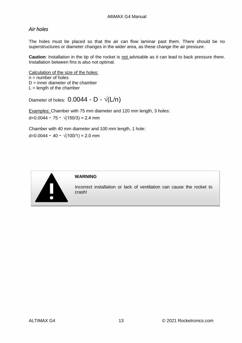
Air holes The holes must be placed so that the air can flow laminar past them. There should be no superstructures or diameter changes in the wider area, as these change the air pressure. Caution: Installation in the tip of the rocket is not advisable as it can lead to back pressure there. Installation between fins is also not optimal. Calculation of the size of the holes: n = number of holes D = inner diameter of the chamber L = length of the chamber
Diameter of holes: 0.0044 - D - √(L/n)
Examples: Chamber with 75 mm diameter and 120 mm length, 3 holes:
d=0.0044 - 75 - √(150/3) = 2.4 mm
Chamber with 40 mm diameter and 100 mm length, 1 hole:
d=0.0044 - 40 - √(100/1) = 2.0 mm
WARNING Incorrect installation or lack of ventilation can cause the rocket to crash!
AltiMAX G4 Manual
ALTIMAX G4 14 © 2021 Rocketronics.com
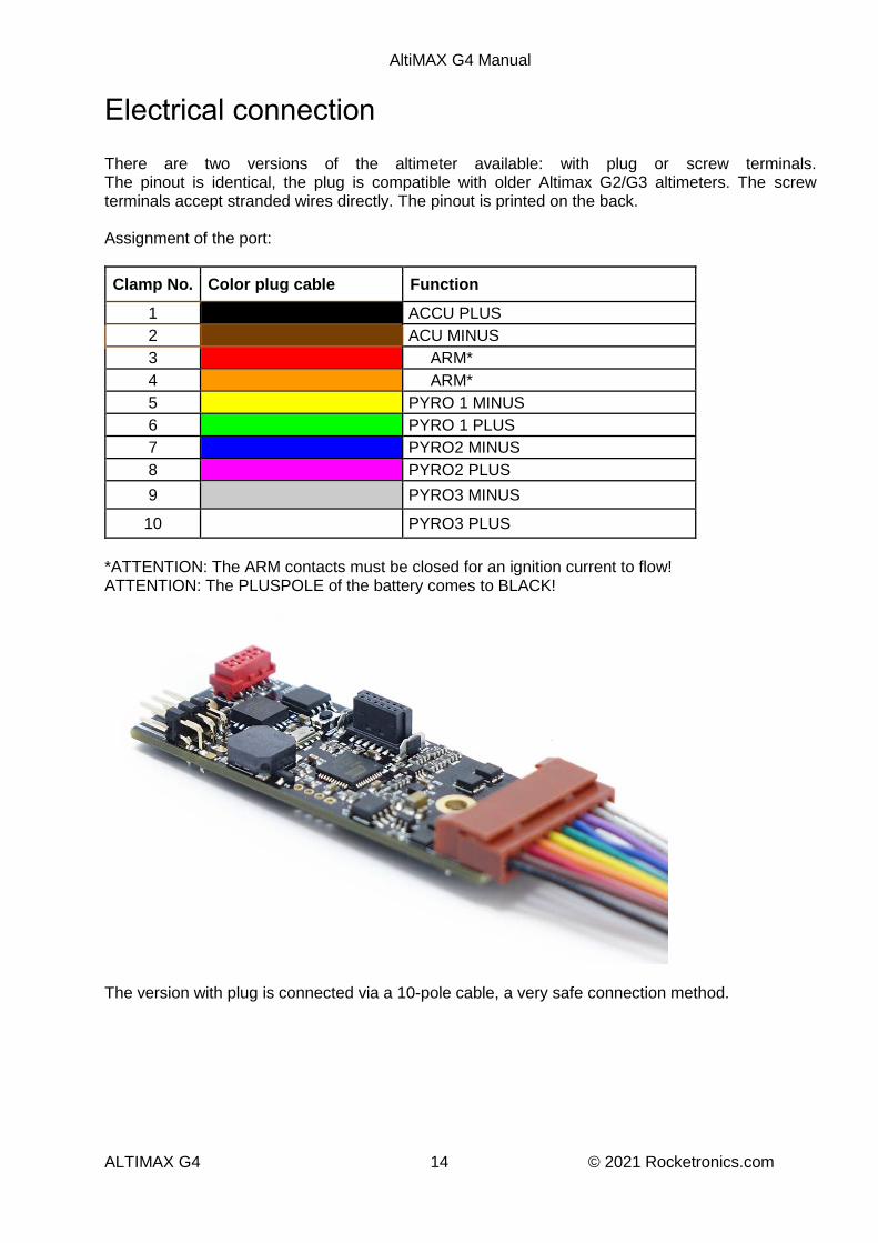
Electrical connection There are two versions of the altimeter available: with plug or screw terminals. The pinout is identical, the plug is compatible with older Altimax G2/G3 altimeters. The screw terminals accept stranded wires directly. The pinout is printed on the back. Assignment of the port:
Clamp No. Color plug cable Function
1 ACCU PLUS
2 ACU MINUS
3 ARM*
4 ARM*
5 PYRO 1 MINUS
6 PYRO 1 PLUS
7 PYRO2 MINUS
8 PYRO2 PLUS
9 PYRO3 MINUS
10 PYRO3 PLUS
*ATTENTION: The ARM contacts must be closed for an ignition current to flow! ATTENTION: The PLUSPOLE of the battery comes to BLACK!
The version with plug is connected via a 10-pole cable, a very safe connection method.
AltiMAX G4 Manual
ALTIMAX G4 15 © 2021 Rocketronics.com
Power supply The Altimax G4 is supplied with a DC voltage of 7 - 12 volts. The voltage connection is protected against polarity reversal. The current consumption is approx. 30mA in wait position and without servos. With servos connected, this can be up to 1A. Accumulators and batteries supply a nominal voltage that becomes lower the more current is drawn. If a limit is exceeded during the current draw, the voltage will collapse. It is essential that the voltage does not drop below 5.5 V at any time during the flight, whether due to ignition or interruptions. Even a short interruption will inevitably cause a restart of the altimeter (system reset). During the flight this leads to an undefined state where the intended recovery can no longer be guaranteed, in most cases a crash is the result. Therefore, an interruption or too deep a voltage drop must be avoided in any case! This is the most frequent reason for malfunctions of the recovery system! Therefore, check the batteries, plugs, terminals and switches for suitability; they must also guarantee safe contact under acceleration and impact (e.g. during ejection or landing!). Many cheap slide switches are not suitable, some plugs or terminals are not suitable either.
Magswitch We recommend the use of our very reliable MAGSWITCH to switch on the altimeter. This allows the switch-on from the outside by a magnet, mechanical contacts are thus eliminated.
Batteries Very suitable are common fully charged LIPO batteries with 2 or 3 cells and 150-800mAh. 9V batteries can be used, but are not always acceleration resistant or high current capable. The higher the voltage, the more safety reserves are available during ignition. If a high ignition current is required, the battery voltage drops during an ignition process. The ignition current is controlled by BROWNOUTPROTECT so that internally at least 5.5V is always available. See also the description in the next chapter. Therefore, we advise the following batteries: Ignition via bridge igniter A or U, Firstfire or other low-current igniters: 2s-Lipo with 7,4V and 150-800mAh High current igniter (e.g. for Aerotech engines), glow wire igniter, etc.: 3s-Lipo with 11,1V and 300-800mAh If servos are connected, you should plan enough capacity to be able to survive longer waiting times on the launch pad. With a maximum current of 1A to the servos, 1000mAh is taken from the battery per hour!
CAUTION An interruption of the power supply in flight can cause the rocket to crash! An undersized power supply can lead to malfunctions!

AltiMAX G4 Manual
ALTIMAX G4 16 © 2021 Rocketronics.com
Ignition outputs New: With FETCHECK and BROWNOUTPROTECT! The Altimax G4 has 3 transistor outputs for 3 ignition channels, Pyro1, 2 and 3 at terminals 5,6,7,8,9 and 10. These channels are controlled by 3 field effect transistors (FET). Each channel has 2 terminals, plus and minus, an igniter can be connected directly to these terminals. The outputs can provide up to 15A continuous current at 12V voltage and are activated for the duration of 3 seconds during an ignition event. For short pulses they can switch up to 40A. ATTENTION: By short-circuiting the outputs, high currents flow which can lead to damage to the altimeter. With large Lipo batteries, this can quickly be 100A and more. Such damages are not covered by the warranty. It is switched in open-source circuit: One terminal of the output is supplied with battery voltage. In the event of activation, the other terminal is pulled to ground, thus closing the circuit. In the armed state, voltage is always present at one terminal of the ignition channel, so any cables connected to it should always be well insulated!
ARM connector The ARM connection is located at terminals 3 and 4 of the connection. ARM comes from "to arm". These terminals are used to arm the ignition outputs. If both terminals are open, no voltage can reach the ignition channels. If the terminals are connected, the battery voltage is applied to the ignition channels. It is therefore necessary to install a switch here OR to connect the two terminals permanently so that an ignition current can flow! It increases the safety if you provide a switch here that applies the ignition current to the igniters only shortly before the start, so an accidental triggering of the ignition charges can be prevented.
FETCHECK The Altimax G4 has with FETCHECK a possibility to check the ignition transistors before the flight. In the first step the FETs are checked that they can switch. If this is successful, it is checked whether they are permanently conducting due to damage. Both conditions can occur due to overload and would either prevent an igniter from firing, or worse, fire the igniter immediately after arming. FETCHECK prevents this, if a fault is detected the altimeter goes into alarm mode and does not enable the ignition outputs, the igniters therefore do not receive voltage and cannot be triggered. This test is carried out immediately after switching on the altimeter and can also be carried out with connected igniters without any problems, since only a very low test current of 1 mA flows which cannot trigger an igniter.
BROWNOUTPROTECT This safety function prevents a voltage drop during an ignition process. The battery voltage is monitored continuously, if it drops below 5.5V due to an ignition process and correspondingly high current consumption, the ignition current is limited repeatedly for a short time so that the battery-voltage can rise again. The reaction time is in the microsecond range and pulses the ignition current so that the CPU core always receives sufficient voltage, a reset is thus avoided. The igniters nevertheless receive enough current for a safe ignition, since they are quite sluggish and hardly cool down during the short current interruptions, thus maintaining the ignition process. This function should not tempt to fly with empty accumulators or batteries, it must still be possible to supply enough current for the ignition process.

AltiMAX G4 Manual
ALTIMAX G4 17 © 2021 Rocketronics.com
External ignition power supply It is possible to connect a separate power supply for the igniters, so that the supply of the system is not influenced during the ignition process. Up to 12V can be connected directly to the igniters. In this case, leave terminal 3 unconnected and connect an external battery between terminals 2 and 4:
+_
ARM
LEDs for testing the outputs With LEDs the outputs can be tested well, solder LEDs with 1 K-Ohm resistor to a cable connector, so you can always quickly test if an output is switched, e.g. during the vacuum cleaner test.
Vacuum cleaner test A simple method to test the Altimeter is the vacuum cleaner method: Put the Altimeter with the battery in a bag. Switch it on. As soon as it is ready to start, suck the air out of the bag with your mouth or the vacuum cleaner, after 4-5 seconds slowly let the air back in. This simulates an ascent by reducing the pressure.
The Altimax performs the event system tasks and activates the outputs accordingly. If you connect LEDs (with 1K-Ohm series resistor) to the pyro outputs, you can observe how the outputs are activated.

AltiMAX G4 Manual
ALTIMAX G4 18 © 2021 Rocketronics.com
Automatic igniter test For tests of the recovery system, a possibility to activate the ignition outputs in a controlled manner is often required. The automatic ignition test is used for this purpose. DANGER: This ignites connected igniters! Pay attention to your safety and a safe environment! Fire hazard! Pressing and holding the small button on the altimeter triggers the automatic igniter test. Pressing it again cancels the test. Switching the altimeter off also interrupts the process. Alternatively, the test can be activated via the LCD terminal or the PC software.
The test runs as follows: After the test is activated, an alternating beep is emitted for the set "assembly time", but at least for 20 seconds. During this time, you can bring yourself and others to safety or cancel the test. This waiting time is followed by 4 seconds of short warning tones for each ignition channel, a long warning tone and immediately the subsequent activation of the output for 3 seconds. Pyro output 1, 2 and 3 are activated one after the other and the igniters connected to them are initiated. If the altimeter restarts during an ignition process, you know that the power supply was not sufficiently dimensioned. The sequence of tones is thus: ♫ ♫ ♫ ♫ ♫ ♫ ♫ ♫ ♫ ♫ ♫ ♫ ♫ ♫ ♫ ♫ ♫ ♫ ♫ (at least 20 seconds long)
━ ━ ━ ━━ Pyro 1 ━ ━ ━ ━━ Pyro 2 ━ ━ ━ ━━ Pyro 3
This is useful e.g. to test the recovery system on the ground, with the rocket lying on soft ground you can test if parachute and lines are ejected correctly, the ejection charge is dimensioned correctly and the power supply works safely. Such a real test should be performed at least once for each rocket!
WARNING A test of the ignition outputs can lead to ignition of connected igniters. Always ensure a safe environment!

AltiMAX G4 Manual
ALTIMAX G4 19 © 2021 Rocketronics.com
Servo Connection Two usual RC servos can be connected, in addition the altimeter supplies 5.0V voltage and a control signal with 3.3V. Up to 1A can be supplied. The servos are connected to the two pin headers. If more than 1A current or a higher voltage than 5V is required, e.g. for very large servos, a separate battery can be used for the servos and only the control signal can be used for the controller. The ground of the battery must be connected to the ground of the servo connector. Via the PC software or the LCD terminal the positions of the servos can be set, there is a rest position and a position in the triggered state. In the settings, the servos must also be assigned to an event at which they are triggered. The default setting is:
Servo 1 at the peak Servo 2 when falling below 150 m in the descent after the apogee point.
Servos can be used to open flaps to eject parachutes, for example.
Servo 1Servo 2
- G
ND
+ 5
V~
Sig
nal

AltiMAX G4 Manual
ALTIMAX G4 20 © 2021 Rocketronics.com
Connection G4 Connector The G4 Connector is plugged onto the multi-pin connector, you cannot plug it in the wrong way around. The connector allows the connection to a PC (WindowsXP-10) via USB to read out flight data and change settings or do tests. A micro USB socket at the end of the connector is used for this purpose. If the connector is connected to the PC via USB, a "virtual comport" is set up there via which the software can communicate with the altimeter. The red/green LED indicates activity. Drivers for this are available at https://www.rocketronics.de/downloads/altimax-downloads/
LCD terminal: There is also a 6-pin header on the connector to accept the plug of the LCD terminal. One pin is intentionally missing there as polarity reversal protection. MICRO-SD CARD: There is a socket for a micro SD card on the back. Insert a micro SD card with a software update for the Altimax G4 here to update the software when the altimeter starts. The process takes only 5 seconds, all settings are preserved.
CAUTION: Nothing must be connected to the AUX I/O port for a software update! Disconnect any connected plugs beforehand. On the back you will also find a 4-pin female connector, with which the Connector can be plugged into older Altimax G2 and G3, in order to establish a USB connection. So it replaces the old USB connector!

AltiMAX G4 Manual
ALTIMAX G4 21 © 2021 Rocketronics.com
The old USB connector of the Altimax G2/G3 cannot be used on the G4. On the other hand, the connector G4 can also be used with the older models of the Altimax G2 and G3. Make sure that no excessive forces act on the plug connection!
Location of the connector port
Connector plugged onto Altimax g4

AltiMAX G4 Manual
ALTIMAX G4 22 © 2021 Rocketronics.com
Connection LCD terminal The LCD terminal is connected via the USB connector. To do this, the terminal's pin plug is inserted into the socket on the connector and then the connector is plugged into the Altimax G4. The terminal is only recognized when rebooting, so the Altimax must be switched on after plugging it in!
Connection OLED display An optionally available OLED display can be plugged directly onto the connector port. It displays status data such as battery voltage, igniter status and last altitude reached. It can remain plugged in and then displays the altitude reached after a landing.

AltiMAX G4 Manual
ALTIMAX G4 23 © 2021 Rocketronics.com
Connection AUX I/O The Altimax G4 has 3 I/O ports which can be used as logic input or output, logic voltage is 3.3V. The ports can be connected via the 6-pin Micro-Match connector. There are flat cable connectors with Micro-Match connector available, e.g. at Reichelt, Mouser, Digikey, Farnell or other distributors. In addition to the ports there are +3.3V and GND so that external circuits can be supplied with up to 50 mA. If 5V and max. 1A is needed the pin headers of the servo connector can be contacted. Pin assignment:
1
23
45
6
AUX2
AUX1
GND+3,3V
AUX3
NC
ATTENTION: Disconnect cables connected here before you make a software update via the connector, otherwise the SD card will not be recognized!
The ports can be switched as input or output via the PC software. As an output, the pin can be assigned to an event as an action, the output will then change to HIGH when an event occurs. So you can e.g. activate an output after the event "landing" to activate a signal generator. As an input, it generates an event, which in turn can then be used to trigger actions. So you can start a timer, activate a pyro output or move a servo when you activate an input. There are no limits to the imagination here. Use as OUTPUT: As output the pins are connected to ground and are switched to 3.3V (HIGH) when activated. Attention: These pins are not protected against overload! Maximum load on the pins as OUTPUT: Current: 20 mA Voltage: 3.3 V
DANGER The AUX pins are also used to connect the micro SD slot on the connector. When the Altimax G4 is switched on, pulses can be output at these pins. Therefore, never use the AUX pins for critical functions, especially not as control outputs for igniters!

AltiMAX G4 Manual
ALTIMAX G4 24 © 2021 Rocketronics.com
With a series resistor of 180 Ohm a red or green LED with 10 mA can be operated directly at the pins. Everything that needs more than 20 mA current must be switched by a FET or a transistor. For this the pin can drive a transistor directly, bipolar transistors only with resistor, FETs should be driven by a 100 Ohm resistor. Please note the 3.3V maximum output voltage! Not all power FET switch at 3.3V already. AUX 2 and 3 can be used as output function BEEPER or ARMED LED, then the beep signal is output on AUX2. If AUX3 is set to ARMED LED, the output is activated when the Altimax is ready to start. This makes it easy to route the beeper and LED to the outside. Use as INPUT: As INPUT the pin is high impedance and is connected to 3.3V via a pullup resistor. If an input is to be activated, it must be pulled to ground. This is done via a Breakaway contact or a switch that pulls the pin to ground. The event system registers a level change after the altimeter has switched to the start standby mode: If the input was previously pulled to ground by a closed breakaway contact, opening the contact is considered as activation of the input. Conversely, if an open input is closed (pulled to ground) after the change to start readiness, this is interpreted as activation of the input. The decisive factor is therefore the change in the level at the input. With the additional inputs/outputs many things can be solved that were not possible before. For example, a locating beeper can be activated after landing or external circuits can be controlled, e.g. a radio module that sends the GPS position after landing. Also, a safe ignition of the engine can be realized:
AUX1 is set as "Input". The AUX1 event is connected to PYRO3. The contact of a 12V relay is connected to the input AUX1. If the relay switches, AUX1 is
thus pulled to ground. The igniter of the rocket motor is now connected to PYRO3 of the Altimax. The actual motor ignition system is connected to the coil of the relay, not to the engine igniter!
If the relay is now switched via the ignition system, it pulls in, the contact closes and pulls AUX1 to ground.
The level change at AUX1 is detected by the altimeter, PYRO3 is activated. The igniter of the rocket motor is connected to this, the igniter thus ignites the rocket motor.
So you can safely prevent that the rocket takes off if the electronics is not activated, which is sometimes forgotten. If the electronics were forgotten, the rocket motor would not be ignited!

AltiMAX G4 Manual
ALTIMAX G4 25 © 2021 Rocketronics.com
Launch procedure 1. SWITCH ON
First, the status of the igniters is indicated by beeps (see 5). This is useful to briefly check whether the igniters are connected correctly during preparation. The AltiMAX then performs the self-test of the hardware, if the test is not passed a loud alarm sounds and the error is displayed in the terminal, OLED display and in the PC software. If the test is passed, the output of the last reached flight altitude follows by beeps (See at the end of this section).
2. ASSEMBLY TIME A beep sounds for every second that the assembly time is set. When the time has elapsed, a longer beep sounds. So at 5 seconds: beep - beep - beep - beep - beep - beeeeeeeep - This waiting time is counted down in the OLED display.
3. CALIBRATION The AltiMAX then measures the current pressure values at the pad and calculates its flight parameters from them. The accelerometer is set and the status is switched to "ready for takeoff". This all happens in a few milliseconds. Then the altimeter goes into
4. START READY From here on everything is armed! If a launch is to take place afterwards, the rocket must be in launch position, vertically on the launch pad, before reaching this phase! From here on, the system reacts to changes in pressure and acceleration. In this state, the AltiMAX waits for the start, which it then detects when an altitude of approx. 24 m above the pad has been exceeded or when more than 3 G acceleration in the start direction has been measured for longer than 0.1 seconds. While waiting, the beep of the ignition status is repeated continuously:
5. IGNITION TEST The igniters are measured through and the status is indicated by beep tones: Two short beeps for "continuity", one long beep for "interrupted". beep-beep = Igniter has continuity Beeeeeep = Igniter has no continuity, no igniter connected! First Pyro1 then Pyro2 and then Pyro3 are displayed. Pyro1 Pyro2 Pyro3 beep-beep beep beep beep beep =All 3 igniters OK beep-beep beeeeeep beep beep =Z1 OK Z2 not Z3 OK beep beep beep beep beeeeeep =Z1 OK Z2 OK Z3 not OK Attention: When flying with servos only, the pyro outputs can remain free, this does not change the control! Igniters do not necessarily have to be connected.
6. Event control After takeoff, the event system comes into play. According to the predefined event scheme, an event is triggered depending on the flight attitude, which is then linked e.g. to a pyro output, timer start or servo position. The altimeter measures the speed by its acceleration sensor and thus prevents e.g. the triggering of pyro outputs during high speeds. An additional adjustable Mach-Delay provides even more safety during ascent.
7. Sink to landing During descent, the AltiMAX continues to measure altitude to determine if the altitude falls below the "Altitude Descent". In most cases, this will eject the main parachute.

AltiMAX G4 Manual
ALTIMAX G4 26 © 2021 Rocketronics.com
8. Landing
The landing is detected 4 seconds after the real landing, for 4 seconds the altitude must be within 2m. The data record is saved to the end. Please do not switch off before this beep is heard, otherwise the data record will not be finished correctly! With strong wind this can take a little longer. After saving the data the reached altitude is output by beeps. After landing, the OLED display also shows the altitude reached.
The last reached altitude is output 1x at take-off and repeatedly after landing, by beeps, each decimal place is "beeped out": A “1” gives 1x beep, a “2” gives 2x beep etc. “0” is a long beep. Starting with the highest digit, the height is output in this way.
156 m = ♪ 1
♪ ♪ ♪ ♪ ♪ 5
♪ ♪ ♪ ♪ ♪ ♪ 6 => 156 m
502 m = ♪ ♪ ♪ ♪ ♪ 5
♬ 0 (long beep)
♪ ♪ 2 => 502 m
Rule No. 1: Switch on the electronics of a loaded rocket only if the environment is secured!
The Altimax G4 detects a start by movement of the rocket and by pressure changes, these must therefore be avoided at all costs. A start detection with a lying rocket leads to fast triggering of the ignition outputs and is therefore to be avoided in any case! For safety there is the possibility to set an ASSEMBLY TIME, default is 5 seconds, maximum is 254 seconds. You can set the ASSEMBLY TIME accordingly high so that you have enough time to finish everything. During the ASSEMBLY TIME you can do whatever you want with the rocket. If you want to launch the rocket directly, make sure that the rocket is in launch position when the assembly time is over, because then the calibration will be done. For the start, the altimeter must calibrate its sensors. This is done a few milliseconds before the change to launch readiness. If a rocket launch is to take place afterwards, this calibration MUST have taken place in launch position, i.e. vertically on the launch pad. It is NOT possible to switch on the rocket lying horizontally and to let it reach the launch readiness and then to run around with it or to put it only then on the ramp. This can lead to a starter detection, and thus to a triggering of the pyro outputs!
DANGER Ejector charges are a great danger when they are ignited in the direct vicinity of people. It is therefore very important that this is handled responsibly, there have already been serious accidents and injuries due to false triggering of igniters. Therefore, pay close attention to your safety.

AltiMAX G4 Manual
ALTIMAX G4 27 © 2021 Rocketronics.com
It is allowed to switch on the rocket lying down and let it go in readiness for take-off o as long as no igniters are connected o or the ARM contact is open o or the rocket is not moved or tilted when switched on.
So you can switch on the altimeter and let it run during preparation or for tests on the floor or a table. However, do not run around with it then!
It is safe to turn on the altimeter briefly for the igniter test, listen to the beeps for the igniter status and perhaps the last altitude reached, and then turn it off again before launch readiness is reached. However, always ensure a safe environment when doing this.
If a launch is to take place and igniters are connected, the rocket must be in launch position before the launch readiness is reached, and must not be moved much after that.
If the rocket must be removed from the ramp, always switch off the altimeter before changing the inclination of the rocket!
Place the power switch so that you can reach it in launch position without having to change the tilt of the rocket!
No pressure change may be generated in the chamber of the Altimeter after it has reached start-up readiness. Then do not close flaps, do not push any tubes together and do not insert any objects through holes in the chamber (screwdrivers, cables, etc.). Even slight pressure changes can lead to a starter detection!
Use the ARM contacts to increase the safety, thus interrupting the voltage to the igniters.
When the rocket is loaded and ready for launch, treat it like a raw egg, do not move it and do not tamper with it!
WARNING Transporting a loaded rocket with the altimeter armed can lead to triggering of the igniters and ejection charges and possibly to ignition of the rocket motor!

AltiMAX G4 Manual
ALTIMAX G4 28 © 2021 Rocketronics.com
Settings The settings can be changed via the LCD terminal and the PC software. The following things are adjustable in addition to the events:
General settings Assembly time After switching on, there is a one-time output of the igniter states and the output of the last reached flight altitude by beeps. This is followed by a waiting period, which lasts as long as the assembly time is set. This pause is used to perform necessary work on the rocket before the electronics switch to the launch readiness mode. During this time everything is allowed, but after this time the rocket must be in launch position if a launch is to take place! Default setting: 5 seconds. Maximum 254 seconds. Machdelay A delay time after start detection that prevents pyro or servo outputs from being triggered. Useful especially to prevent false triggering during supersonic flights. If this time is set in such a way that the range of the supersonic flight is covered, no igniter can be triggered during the passage to supersonic. Use this as an additional backup in this case. Default setting: 2 seconds. Units Here you can set in which units data should be displayed on the LCD terminal, metric (m/hpa) or imperial (ft /inHg). Stormtroopers take Imperial units, Rebels metric :-). Standard is Metric Height ascent When this height is exceeded, the "Height Ascent" event is triggered. Standard is 100m Height descent When falling below this height, the event "Height descent" is triggered. The event is only recorded after reaching the apogee point! Standard is 150m Timer n Sequence The time after which the three timers expire, after which a "Timer Expiration" event is triggered.
Servo + AUX I/O settings Servo position The servo positions can be set separately for both servos. There is a rest position which is approached after system start. The end position is reached when the servo is activated. There is an option to move the servos to full travel for 3 seconds at system start, e.g. to open flaps. See "Software". AUX I/O The 3 I/Os AUX1-AUX3 can be switched as input or output.
AltiMAX G4 Manual
ALTIMAX G4 29 © 2021 Rocketronics.com
If they are switched as input, a change of edge at this input triggers a corresponding event. Shortly before the change to the start readiness, the state of the input is stored, a change after the change to the start readiness then triggers an event. As an output, the outputs can be used for switching purposes, but pay attention to the currents and voltages of the hardware. Special functions can also be assigned:
Aux 1 can pass the signals of the LEDs of the Altimax Aux 2 can pass the signals of the signal generator Aux 3 can be activated when ready to start.
For example, external signal transmitters can be connected or an LED can be led to the outside to indicate readiness to start.
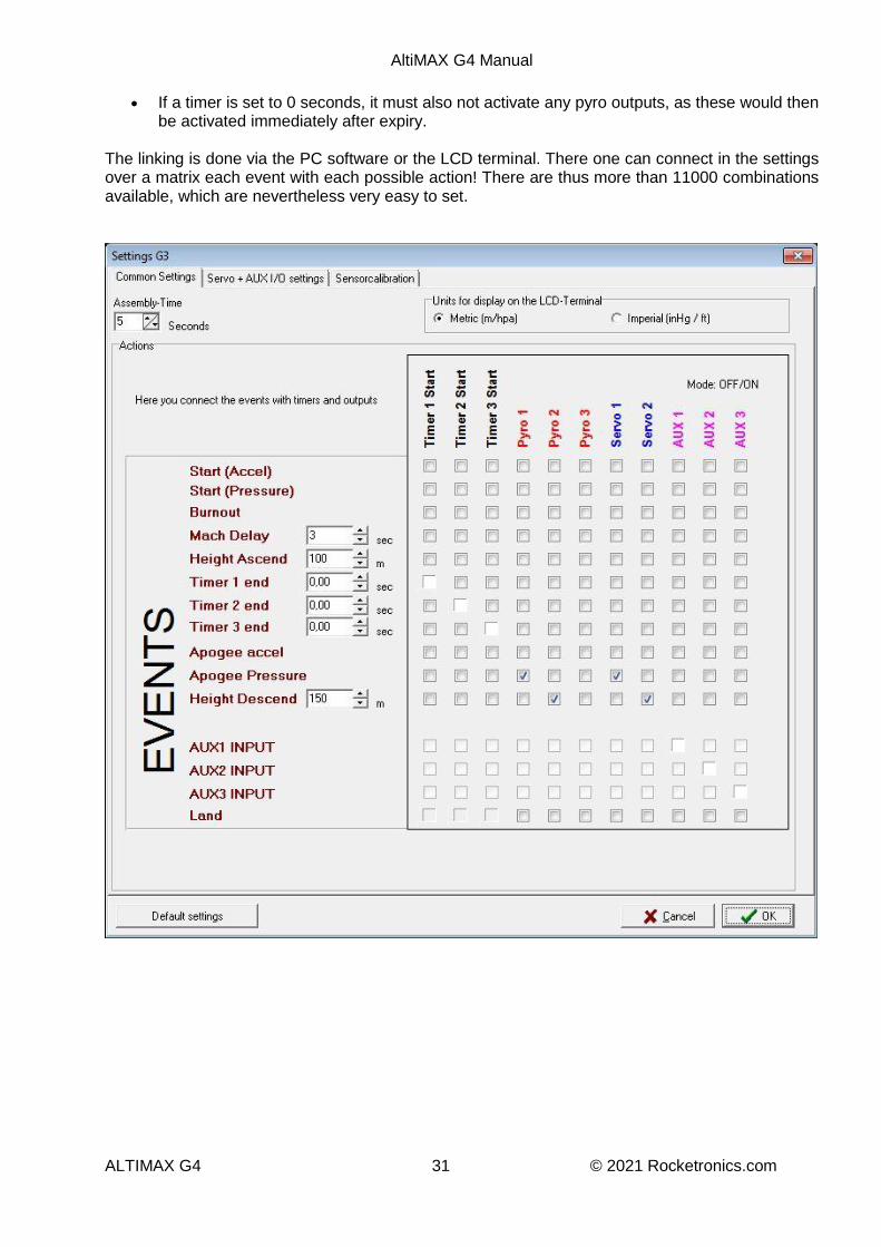
The following values are set ex works: Assembly time: 5 seconds Mach delay: 3 seconds Height ascent: 100 m Height descent: 150 m Servo deflections: Rest -100, end deflection +100 (100 is full deflection). All AUX set to OUTPUT Pyro 1 and Servo 1 are activated at "Peak point At "Height Descent" Pyro 2 and Servo 2 are activated.
The Altimax is also delivered in this setting. This way a standard two-stage recovery is possible, the drogue chute is ejected by Pyro 1, the main chute by Pyro 2 (or servo 1 and servo 2).
DANGER The AUX pins are also used to connect the micro SD slot on the connector. When the Altimax G4 is switched on, pulses can be output at these pins. Therefore, never use the AUX pins for critical functions, especially not as control outputs for igniters!

AltiMAX G4 Manual
ALTIMAX G4 30 © 2021 Rocketronics.com
Altimax event system The Altimax G4 has an event system unique to altimeters. It allows the linking of input signals, events and timers with actions and thus allows a very flexible response to attitude changes and times. Events are generated by level changes at the 3 digital inputs, by reaching certain flight positions (e.g. reaching the peak), or by the expiration of one of the three timers. Internally, a series of events is generated by the flight attitude evaluation. POSSIBLE EVENTS:
Start (acceleration) - detected by acceleration Start (pressure) - detected by pressure change Combustion closure - when the thrust of the engine ends Machdelay - When the Machdelay timer has expired Altitude ascent - Altitude exceeded during rocket ascent Timer 1 End - Sequence of an adjustable timer Timer 2 End Timer 3 End Apogee acceleration - Apogee point calculated by acceleration Apogee pressure - Apogee point calculated by pressure change Height descent - Altitude undershot after reaching the apogee point AUX1 level change - When the level of input AUX1 changes AUX2 level change - Dito for AUX2 AUX3 level change - only if the AUXn is also set as input! Landing
POSSIBLE ACTIONS
Timer 1 Start - Starts timer 1 Timer 2 Start - Starts timer 2 Timer 3 Start - Starts timer 3 PYRO 1 - Activates output Pyro 1 PYRO 2 - Activates output Pyro 2 PYRO 3 - Activates output Pyro 3 SERVO 1 - Activates output servo 1 SERVO 2 - Activates output servo 2 AUX1 - Activates digital output AUX1 (if this is set as output!) AUX2 - Activates digital output AUX2 (if this is set as output!) AUX3 - Activates digital output AUX3 (if this is set as output!)
Actions can be used multiple times! For example, you can link an AUX output to more than one event. TIMER When an event occurs, one of the 3 timers can be started as an action. The expiry time of the timers can be set in steps of 0.25 seconds. After the time has elapsed, an event "TIMER expiry" is triggered again, which in turn can trigger an action, e.g. activate an output. The timers can therefore be used to build in delays in the sequence or even to switch the entire operation of the Altimeter to timer mode. Exceptions:
Each event can occur exactly 1x, a repetition is not possible. Timer sequence cannot restart the same timer (this would result in an infinite loop)
AltiMAX G4 Manual
ALTIMAX G4 31 © 2021 Rocketronics.com
If a timer is set to 0 seconds, it must also not activate any pyro outputs, as these would then be activated immediately after expiry.
The linking is done via the PC software or the LCD terminal. There one can connect in the settings over a matrix each event with each possible action! There are thus more than 11000 combinations available, which are nevertheless very easy to set.

AltiMAX G4 Manual
ALTIMAX G4 32 © 2021 Rocketronics.com
Examples: The application is simple: If, for example, you want to ignite a igniter with output Pyro 1 at the peak height of the trajectory, connect the event "Apogee (Pressure)" with action "Pyro1". Then, when you reach the top, the exit is activated. Example 1: Two-stage recovery Pyro1 = Drogue Pyro2 = Main chute
"Height descent" we set to 100m At the event "Apogee pressure" we set action "Pyro1". At the event "Height descent" we set action "Pyro2".
When reaching the apogee, Pyro 1 is then ignited, the drogue chute comes out. After falling below the set 100 m altitude, Pyro 2 is ignited, the main parachute comes out. Example 2: Control of the recovery according to time, timer operation, so to speak. Pyro1 = Drogue Pyro2 = Main chute
Timer 1 is set to 7 seconds Timer 2 to 20 seconds At the "Start" event we set actions "Timer 1 Start" and "Timer 2 Start". At the event "Timer 1 End" we set action "Pyro 1". At the event "Timer 2 End" we set action "Pyro 2".
At startup, the two timers are then started. After 7 seconds timer 1 runs and triggers output Pyro 1, 13 seconds later (20 seconds from start) timer 2 runs and triggers output Pyro 2, Example 3: Two-stage flight with two-stage recovery of the 2nd stage The Altimax G4 is thereby installed in the 2nd stage! Pyro1 = Drogue Pyro2 = Main chute Pyro3 = igniter for 2nd stage motor
Timer 1 is set to 0.5 seconds Height descent is set to 100 m Timer 1 is set at the "Burnout" event Pyro 3 is set at the event "Timer1 end" Pyro 1 is set at the "Apogee" event Pyro 2 is set at the "Height descent" event
When the first stage is burned out the altimeter registers this, at the event burnout then starts timer 1. This has expired after 0.5 seconds and ignites pyro 3. With this the motor of the 2nd stage starts, flies up. At the apogee, the normal two-stage recovery then runs: Drogue with Pyro 1, main chute at 100 m altitude with Pyro 2. Example 4: Ignition of a "Sparky" titanium engine at 40 m above ground. Afterwards normal two-stage recovery. The rocket flies first with a normal motor, which is ignited normally. Pyro1 = Drogue Pyro2 = Main chute Pyro3 = igniter for titanium engine
Height ascent is set to 40 m. Height descent is set to 100 m., Pyro 3 is set at the "Height Ascent" event Pyro 1 is set at the "Apogee" event Pyro 2 is set at the "Height descent" event
The main engine is ignited, the rocket flies off. At a height of 40 m Pyro 3 is triggered and ignites the titanium engine. At this altitude, the sparks can do no damage and look great! After that the rocket flies on and is recovered with two-stage recovery.
AltiMAX G4 Manual
ALTIMAX G4 33 © 2021 Rocketronics.com
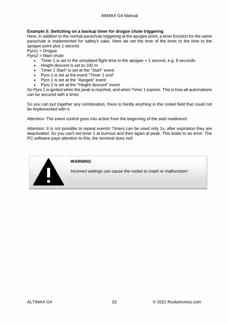
Example 5: Switching on a backup timer for drogue chute triggering Here, in addition to the normal parachute triggering at the apogee point, a timer function for the same parachute is implemented for safety's sake. Here we set the time of the timer to the time to the apogee point plus 1 second. Pyro1 = Drogue Pyro2 = Main chute
Timer 1 is set to the simulated flight time to the apogee + 1 second, e.g. 8 seconds Height descent is set to 100 m Timer 1 Start" is set at the "Start" event Pyro 1 is set at the event "Timer 1 end" Pyro 1 is set at the "Apogee" event Pyro 2 is set at the "Height descent" event
So Pyro 1 is ignited when the peak is reached, and when Timer 1 expires. This is how all automations can be secured with a timer. So you can put together any combination, there is hardly anything in the rocket field that could not be implemented with it. Attention: The event control goes into action from the beginning of the start readiness! Attention: It is not possible to repeat events! Timers can be used only 1x, after expiration they are deactivated. So you can't set timer 1 at burnout and then again at peak. This leads to an error. The PC software pays attention to this, the terminal does not!
WARNING Incorrect settings can cause the rocket to crash or malfunction!

AltiMAX G4 Manual
ALTIMAX G4 34 © 2021 Rocketronics.com
Software update The Altimax G4 can be updated very easily without a computer, you need the USB connector and a micro-SD card. Download the latest software from https://www.rocketronics.de/downloads/altimax-downloads/ Be sure to load the correct software for the Altimax G4.
Save the file "alti-g4.dld" in the archive to an empty micro SD card. It is important that the file is located right at the beginning of the card's memory, therefore the card must be empty.
The card must have at least 2 GB of memory and be formatted with FAT32. Log the card off the PC, wait for it to be released before unplugging it, and then plug it into
the socket of the USB connector. Plug the connector into the Altimax G4 and then simply turn on the altimeter. When the file is recognized, you will hear a clicking sound and the LEDs will blink, after about
8 seconds the update is finished and the Altimeter will go into normal startup mode. If the file is not recognized you will not hear a clicking sound, in this case repeat the procedure or try another SD card.
Switch off the altimeter and disconnect the connector. Attention: The update does not overwrite any settings! Everything is preserved. The update is always executed if an update file is found during startup. Therefore, remove the SD card after an update to avoid a repeated update.

AltiMAX G4 Manual
ALTIMAX G4 35 © 2021 Rocketronics.com
Using the PC software At least version 4 of the PC-software is required for the Altimax G4!
Installation For installation please call the file Altimax_Setup.exe and follow the instructions.
Updates The latest version is available on the website at http://www.rocketronics.de/download/Altimax.exe
Features of the software The software runs under Windows and allows the adjustment of the AltiMAX. In addition, one can read out the stored flight data and display them graphically. The third function is the tests, the software allows the controlled triggering of the igniters as well as tests of the servo.
User interface The surface is divided into three parts: At the top is the menu and the toolbar with buttons for quick access to the functions On the left is the status panel, where the most important operating parameters of the AltiMAX are displayed. On the right are the flight data pages, flight 1 to flight 6. Each flight has its own page that displays the data, so you can quickly compare flights.
Menu and toolbar File

AltiMAX G4 Manual
ALTIMAX G4 36 © 2021 Rocketronics.com
Open* Opens an . alx file, a file with flight data of the AltiMAX This data is loaded into the currently selected flight data page.
Save* Saves the data of the current flight data page to an . alx file Export to Excel* Exports the flight data to Excel Exit Exits the software AltiMAX Setting* Opens the settings dialog Tests* Opens the Tests dialog Options Program settings Setting of units and Comports. Show terminal Shows a terminal with the data traffic of the serial port Select Comport Allows the selection of a Comport Calculate air holes Allows the calculation of the optimal air hole diameter Firmware Update Allows updating the firmware of the AltiMAX G1-G3 Help Help Online help About AltiMAX Software Version display *These functions are also accessible as buttons in the toolbar.

AltiMAX G4 Manual
ALTIMAX G4 37 © 2021 Rocketronics.com
Setting the COM port At the first call the software probably asks for the comport to be used. If this is to be changed later, the port can be changed here. A restart of the software after changing the port can be necessary. The AltiMAX is connected to the PC via the USB Connector. This connector provides a virtual serial port in the computer over which the communication runs. These ports are numbered and labeled COMx. If the PC still has a serial port, this is usually COM1, but these have become rare, usually a PC has only USB interfaces. The Altimax USB connector sets up a port with higher number, mostly from COM 6 or higher. The selection dialog shows the available ports in the list. In case of doubt just try it out.

AltiMAX G4 Manual
ALTIMAX G4 38 © 2021 Rocketronics.com
Establish serial connection If the Comport is selected and the adapter is connected to the AltiMAX, the software will query the status of the AltiMAX every 1 second. If a connection has been established, this is displayed: At the bottom left of the program window there are 4 color areas:
Connected!
Not connected! RXD - data traffic on the receive line TXD - data traffic on the transmission line ERR - Error Large area: Green = Connected, RED = Not connected. If the large area remains red, something is wrong with the connection, please check the following:
Correct com port selected?
Adapter connected correctly?
AltiMAX switched on?

AltiMAX G4 Manual
ALTIMAX G4 39 © 2021 Rocketronics.com
When the connection is established, the status data is read out and displayed in the table on the left side of the window. The status can be updated by clicking the "STATUS" button above the table. The following status data is displayed: Firmware Version of the internal software Hardware Hardware version G4STD Battery Battery voltage in volts Pyro #1 Igniter 1 status Pyro #2 Status igniter 2 Pyro #3 Status igniter 2 Last flight no. The last flight number used Number of flights The number of possible stored flights Waiting time Set waiting time, this is waited after switching on. Mach-Delay Delay after take-off, flight data is only evaluated after expiration. Height descent Height limit during descent, mostly ejection height of the main parachute Pressure Actual air pressure in Hpa (mbar) Flight altitudes The stored flight altitudes of the last n flights. "n" is the number that is set under
"Number of flights". If "NO DATA" is displayed here, nothing is stored under the flight number.
AltiMAX G4 Manual
ALTIMAX G4 40 © 2021 Rocketronics.com
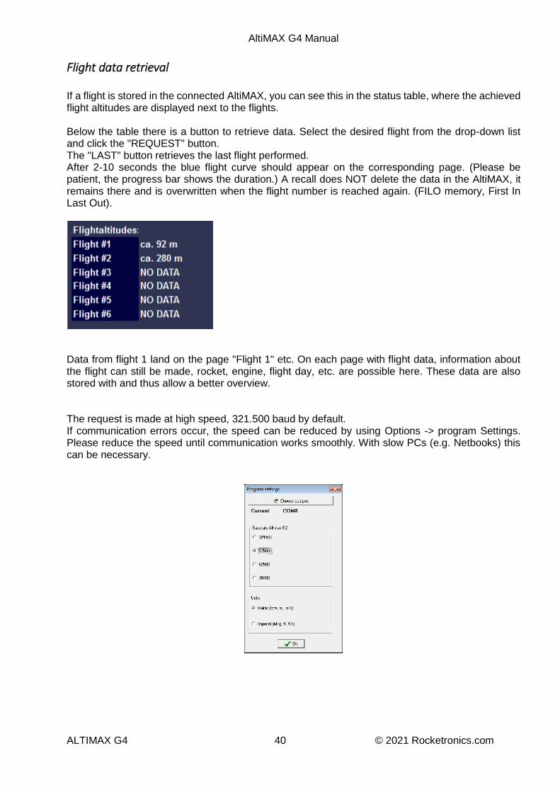
Flight data retrieval If a flight is stored in the connected AltiMAX, you can see this in the status table, where the achieved flight altitudes are displayed next to the flights. Below the table there is a button to retrieve data. Select the desired flight from the drop-down list and click the "REQUEST" button. The "LAST" button retrieves the last flight performed. After 2-10 seconds the blue flight curve should appear on the corresponding page. (Please be patient, the progress bar shows the duration.) A recall does NOT delete the data in the AltiMAX, it remains there and is overwritten when the flight number is reached again. (FILO memory, First In Last Out).
Data from flight 1 land on the page "Flight 1" etc. On each page with flight data, information about the flight can still be made, rocket, engine, flight day, etc. are possible here. These data are also stored with and thus allow a better overview. The request is made at high speed, 321.500 baud by default. If communication errors occur, the speed can be reduced by using Options -> program Settings. Please reduce the speed until communication works smoothly. With slow PCs (e.g. Netbooks) this can be necessary.

AltiMAX G4 Manual
ALTIMAX G4 41 © 2021 Rocketronics.com
Flight data graphic Flight data read from the AltiMAX as well as data read from a file are displayed graphically in the software. A flight graphic looks something like this:
Visible graphs and data Several curves are displayed:
White is the height curve as calculated from the pressure data.
Red is the curve calculated by the AltiMAX using a Kalman filter. This data is internally used for finding the apogee point.
Yellow is the speed in m/s, please note that the speed from the apogee is calculated from the pressure values, the values are only approximate. Values before the apogee are from the accelerometer and are very accurate. After chute separation the rocket tumbles.
Green is the acceleration in m/s2
The events such as START, MACHDELAY, APOGEE, MINIMUM HEIGHT, LANDING, etc. are displayed, along with the altitude to these events. Above the graphic, the most important flight data such as start time, peak (APO), max. Altitude, and Vmax are displayed.

AltiMAX G4 Manual
ALTIMAX G4 42 © 2021 Rocketronics.com
Selection of the data curves to be displayed At the top of the program window there is a selection box from which you can switch the individual data sets on and off.
Here you can select the data you want to have. Especially with the on-board voltages there is otherwise quickly confusion. For the analysis of the voltages I recommend to switch off everything else, then you can still see the events and the voltage values.
Evaluate on-board voltages The selection box for the voltages allows a finer subdivision of which voltage is to be displayed. VBatt = Battery voltage VIGN = Ignition voltage at the igniters VPyro1 = Voltage at pyro 1 VPyro2 = Voltage at pyro 2 VPyro3 = Voltage at pyro 3 Every change leads to an immediate update of the graphic! Alternatively, this setting can also be achieved by right-clicking on the graphic while holding down the CTRL key. Then a small popup menu opens at the mouse cursor.

AltiMAX G4 Manual
ALTIMAX G4 43 © 2021 Rocketronics.com
SHOW DATA POINTS You can click on the curve, then at the bottom of the status bar the data such as time, altitude and speed to this point are displayed. ZOOM A zoom of the graphic is also possible: To zoom in on a diagram area, press the left mouse button and drag the mouse down to the right. You will see a rectangle surrounding the selected area. Release the left mouse button again to start zooming. You can repeat this process as often as you like. To RETURN the zoom (or make it BACK), drag a rectangle in the opposite direction (down to the left).
Zoom in: Zoom out: PAN (Move) The graphic can be moved with the right mouse button. Just click and move the mouse.
AltiMAX G4 Manual
ALTIMAX G4 44 © 2021 Rocketronics.com
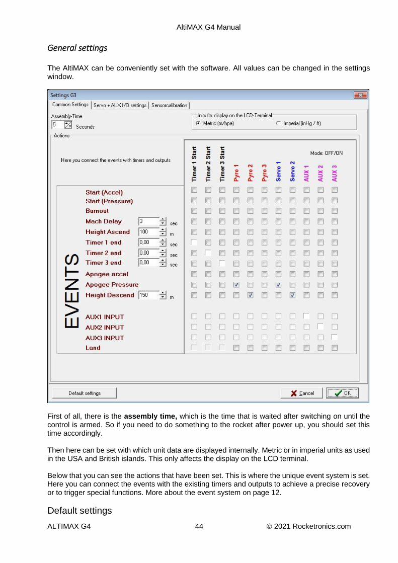
General settings The AltiMAX can be conveniently set with the software. All values can be changed in the settings window.
First of all, there is the assembly time, which is the time that is waited after switching on until the control is armed. So if you need to do something to the rocket after power up, you should set this time accordingly. Then here can be set with which unit data are displayed internally. Metric or in imperial units as used in the USA and British islands. This only affects the display on the LCD terminal. Below that you can see the actions that have been set. This is where the unique event system is set. Here you can connect the events with the existing timers and outputs to achieve a precise recovery or to trigger special functions. More about the event system on page 12.
Default settings

AltiMAX G4 Manual
ALTIMAX G4 45 © 2021 Rocketronics.com
The "Defaults" button restores the defaults, these are:
Assembly time: 5 seconds
Mach delay: 3 seconds
Height ascent: 100 m
Height descent: 150 m
Servo deflections: Rest -100, end deflection +100 (100 is full deflection)
Pyro 1 and Servo 1 are activated at Apogee.
At "Height Descent" Pyro 2 and Servo 2 are activated.
All other event actions will be deleted. The Altimax is also delivered in this setting. This way a standard two-stage recovery is possible, the drogue chute is ejected by Pyro 1, the main chute by Pyro 2 (or Servo1 and Servo 2).

AltiMAX G4 Manual
ALTIMAX G4 46 © 2021 Rocketronics.com
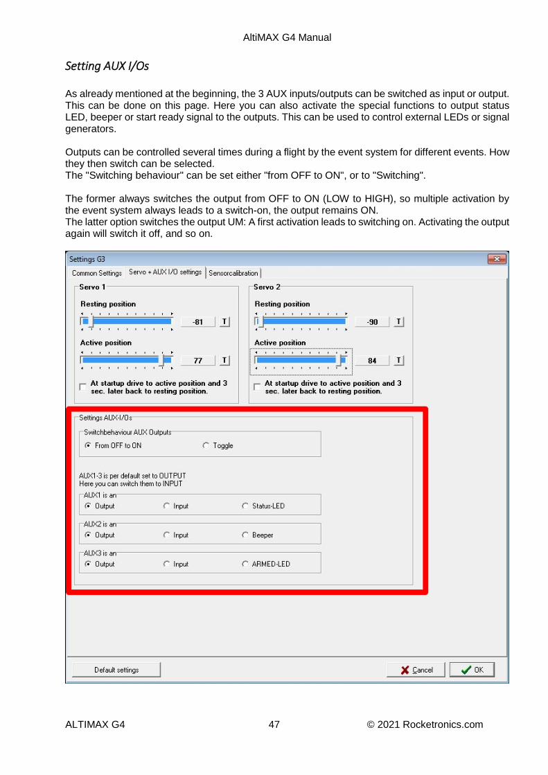
Servo+AUX I/O settings On this page you can set the servo positions and the AUX I/Os. The servos require a rest position, which they reach after power-up, and an active position, which is the position they reach when triggered. Click on the small "T" switches to let a connected servo move to the position, so the adjustments can be made very easily live on the object. The option "Move to full travel on power up and back 3s" does exactly that, it moves the servo to full travel on power up and then back again. This can be used to open flaps when switching on.
AltiMAX G4 Manual
ALTIMAX G4 47 © 2021 Rocketronics.com
Setting AUX I/Os As already mentioned at the beginning, the 3 AUX inputs/outputs can be switched as input or output. This can be done on this page. Here you can also activate the special functions to output status LED, beeper or start ready signal to the outputs. This can be used to control external LEDs or signal generators. Outputs can be controlled several times during a flight by the event system for different events. How they then switch can be selected. The "Switching behaviour" can be set either "from OFF to ON", or to "Switching". The former always switches the output from OFF to ON (LOW to HIGH), so multiple activation by the event system always leads to a switch-on, the output remains ON. The latter option switches the output UM: A first activation leads to switching on. Activating the output again will switch it off, and so on.

AltiMAX G4 Manual
ALTIMAX G4 48 © 2021 Rocketronics.com
Sensor calibration On this page, the zero point of the accelerometer can be set with "Calibrate G-Sensor". This is calibrated ex works, but sometimes there can be a deviation due to drift. This does not hurt, who wants can set it back to 0 here. First retrieve the current value by placing the altimeter flat on the table. Then click on "Test G-Sensor". A message should then appear in the text window:
Output sensor data: Calibration value=-6 Pad Offset= -0.06 G G Raw= 0.00 G G Pad= 0.06 G
Here approx. 0G should appear at the last two values, small deviations of up to 0.3G are normal. If there is a larger deviation click on "Calibrate G-Sensor", please only if the altimeter is lying horizontally flat! A retest should then give a result close to 0G.

AltiMAX G4 Manual
ALTIMAX G4 49 © 2021 Rocketronics.com
Tests
Some tests can be done with the software, for one the ignition outputs can be tested, a servo test moves one of the servos to one or the other position. The ignition outputs are controlled for 3 seconds. In addition, a test of the auxiliary inputs is possible here, or if one of them is set as an input, the state of the auxiliary input. An automatic igniter test is also possible. After activation, this test runs automatically when the AltiMAX is switched on again. See also the topic Igniter on page 20.

AltiMAX G4 Manual
ALTIMAX G4 50 © 2021 Rocketronics.com
Firmware update It is possible to load the latest firmware into the AltiMAX yourself. For this purpose, a wizard has been inserted into the PC software, which carries out the steps for the update. These functions are for older Altimax G1 - G3. The Altimax G4 is updated via a micro SD card on the USB connector. The update is loaded into the AltiMAX via the serial interface, this takes about 12 seconds and can be repeated as often as required. Even in case of aborts nothing is lost, it is completely safe and very simple. The serial adapter must be connected to the AltiMAX for the update. In the menu under Options - Firmware Update you will find the wizard.
At the top left you can see the current firmware version of the connected AltiMAX. If the AltiMAX was off before the wizard was called, -1 is displayed here. There are two ways to load a new firmware:
1. You click on "Request update." Then the software searches for the latest version on the AltiMAX internet site.
2. You click on "Load from file. " and select the file itself.
AltiMAX G4 Manual
ALTIMAX G4 51 © 2021 Rocketronics.com
Both variants result in a file being loaded. If the loading was successful, the change that was made to the retrieved firmware version is displayed in the lower text field when retrieving from the Internet. In the window then appears: START THE FIRMWARE UPLOAD: 1. switch off the Altimax 2. click on START UPLOAD 3. then switch the Altimax on again Follow the instructions! For the upload the AltiMAX must be switched on after clicking "Start upload", if it was already switched on please switch it off first and then on again. The upload will then start, which is indicated by a progress bar. After about 25 seconds it should be finished, and a message announcing this appears. You should then switch the AltiMAX off and on again. If the upload fails, please try again until it works. You can try as often as you like, but please do not start after a failure! The software is then not ready for a flight!

AltiMAX G4 Manual
ALTIMAX G4 52 © 2021 Rocketronics.com
Save data All flight data can be saved to a file. To do this, select the page with the desired flight data and then click the "Save" button. The information in the profile, such as engine, rocket name, etc. are also saved.
Open data The stored data can also be read in again, they end up in the currently displayed flight data page and are displayed there. Any flight data curves present there will be overwritten without warning!
Export data The data displayed on a flight page can be exported to Excel as altitude values. To do this, select the page and click on "Export to Excel".
AltiMAX G4 Manual
ALTIMAX G4 53 © 2021 Rocketronics.com
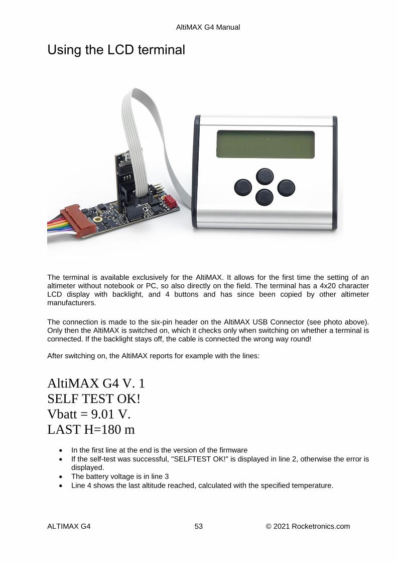
Using the LCD terminal
The terminal is available exclusively for the AltiMAX. It allows for the first time the setting of an altimeter without notebook or PC, so also directly on the field. The terminal has a 4x20 character LCD display with backlight, and 4 buttons and has since been copied by other altimeter manufacturers.
The connection is made to the six-pin header on the AltiMAX USB Connector (see photo above). Only then the AltiMAX is switched on, which it checks only when switching on whether a terminal is connected. If the backlight stays off, the cable is connected the wrong way round! After switching on, the AltiMAX reports for example with the lines:
AltiMAX G4 V. 1
SELF TEST OK!
Vbatt = 9.01 V.
LAST H=180 m
In the first line at the end is the version of the firmware
If the self-test was successful, "SELFTEST OK!" is displayed in line 2, otherwise the error is displayed.
The battery voltage is in line 3
Line 4 shows the last altitude reached, calculated with the specified temperature.

AltiMAX G4 Manual
ALTIMAX G4 54 © 2021 Rocketronics.com
Terminal menu The terminal has 4 buttons, LEFT, RIGHT, UP and DOWN, these are used to navigate in the menu. The menu is arranged horizontally and has the following entries:
SAVE*
ASSEMBLY TIME
MACH-DELAY
HEIGHT ASCEND
HEIGHT DESCENT
TIMER 1
TIMER 2
TIMER 3
SERVO 1 OFF
SERVO 1 ON
SERVO 2 OFF
SERVO 2 ON
AUX SWITCH MODE
AUX 1
AUX 2
AUX 3
ACTIONS
HEIGHTS
BATT-VOLTAGE
IGN-VOLTAGE
CURRENT PRESSURE
IGNITER 1
IGNITER 2
IGNITER 3
AUTO IGN-TEST
UNITS
To enter the LCD menu, press the RIGHT or LEFT key. Now it is possible to jump in the menu with the LEFT and RIGHT keys. The keys UP and DOWN allow to adjust the values for certain values. From there you can change to the other points with LEFT or RIGHT, for example with RIGHT to "MACH-DELAY", but also with LEFT to "SAVE".

AltiMAX G4 Manual
ALTIMAX G4 55 © 2021 Rocketronics.com
In the individual menus, values can be displayed (e.g. CURRENT PRESSURE) or values can be changed. The changes are always made with UP and DOWN. *PLEASE NOTE: In principle, changes must be saved! These are not taken over automatically. To
save, there is a menu item that can be found on the far left. Press the LEFT key several times until the Save menu appears. There the saving of the changes can be initiated with UP. DOWN cancels the
saving.
DON'T FORGET: SAVE! DON'T FORGET: SAVE! DON'T FORGET: SAVE! DON'T FORGET: SAVE! DON'T FORGET: SAVE!

AltiMAX G4 Manual
ALTIMAX G4 56 © 2021 Rocketronics.com
The menu always displays the possible paths, the following characters are used for this purpose:
▲The UP key can be used to navigate upwards or to increase a value
▼ The DOWN key can be used to navigate downward or to decrease a value
► The RIGHT key can be used to navigate to the right
◄ The LEFT key can be used to navigate to the left
Examples:
◄ ASSEMBLY TIME: ► LEFT or RIGHT can be used to switch to the next or previous menu item.
5 sec ▲▼ Here you can change the number of flights with UP or DOWN.

AltiMAX G4 Manual
ALTIMAX G4 57 © 2021 Rocketronics.com
The menu:
AltiMAX G4 v1
SELFTEST OK!
Vbatt = 9.01 V.
LAST H=180 m 20°C Pressing RIGHT or LEFT jumps to the menu, the entries and functions are listed here in order:
AltiMAX G4 v1 Save? (UP=YES)►
UP=YES DOWN=NO ▲▼ Changes are saved here, pressing the UP key saves the changes. DOWN cancels. Attention: If the number of flights has been changed, all flight data will be deleted! A warning is not given! : UP: Save changes DOWN : Do not save changes RIGHT: Continue to next entry
AltiMAX G4 v1 ◄ ASSEMBLY TIME: ►
5 sec ▲▼ The assembly time is displayed here, the AltiMAX waits for this time before arming. Possibilities: UP: Increase number DOWN : Decrease number RIGHT: Continue to next entry LEFT: One entry back
AltiMAX G4 v1 ◄ MACH-DELAY: (sec) ►
2 sec ▲▼

AltiMAX G4 Manual
ALTIMAX G4 58 © 2021 Rocketronics.com
Here the Mach-Delay is displayed, a time which is waited after take-off until the AltiMAX evaluates the pressure values of the sensor. A protection time which is used for flights in the transonic range. Possibilities: UP: Increase number DOWN : Decrease number RIGHT: Continue to next entry LEFT: One entry back
AltiMAX G4 v1 ◄ HEIGHT ASCEND ►
100 m ▲▼ The "Height Ascend" is displayed here, the value indicates the height at which the corresponding event is triggered. The height can be changed in approx. 3 m steps, the allowed range is 12 to 1000 m Possibilities: UP: Increase number DOWN : Decrease number RIGHT: Continue to next entry LEFT: One entry back

AltiMAX G4 Manual
ALTIMAX G4 59 © 2021 Rocketronics.com
AltiMAX G4 v1 -=>> PARAMETER <<=-
◄ HEIGHT DESCEND ►
150 m ▲▼ Here the "Height Descend" is displayed, the value indicates the height at which the corresponding event is triggered. Here mostly the Pyro2 is ignited to eject the main chute with it. But it can also be used in another way. The height can be changed in approx. 3 m steps, the allowed range is 29 to 1000 m Possibilities: UP: Increase number DOWN : Decrease number RIGHT: Continue to next entry LEFT: One entry back
AltiMAX G4 v1 ◄ TIMER 1: ►
7.00 sec ▲▼ Here the time of timer 1 is set, in 0.25 s steps. Possibilities: UP: Increase number DOWN : Decrease number RIGHT: Continue to next entry LEFT: One entry back Proceed accordingly with timer2 and 3.

AltiMAX G4 Manual
ALTIMAX G4 60 © 2021 Rocketronics.com
AltiMAX G4 v1 ◄ SERVO 1 OFF ►
-100 ▲▼ Here the rest position of servo 1 is displayed, this position has the servo on the pad. Possible values are -100 to +100. Changes in steps of 5, a connected servo moves live with! Possibilities: UP: Increase number DOWN : Decrease number RIGHT: Continue to next entry LEFT: One entry back
AltiMAX G4 v1 -=>> PARAMETER <<=-
◄ SERVO 1 ON ►
-100 ▲▼ The trigger position of servo 1 is displayed here, this is the position the servo has when passing through the plaster. Possible values are -100 to +100. Changes in steps of 5, a connected servo moves live with! Possibilities: UP: Increase number DOWN : Decrease number RIGHT: Continue to next entry LEFT: One entry back Proceed accordingly with servo 2

AltiMAX G4 Manual
ALTIMAX G4 61 © 2021 Rocketronics.com
AltiMAX G4 v1 -=>> PARAMETER <<=-
◄ AUX SWITCHING MODE ►
OFF/ON ▲▼ Here you can set how the additional outputs are switched: OFF/ON means they are switched only from OFF to ON. SHIFT means that they are switched during each operation. With Toggle you can e.g. switch ON with one event and OFF with another. With OFF/ON, they are only turned on, no matter how many times the operation occurs. Possibilities: UP/DOWN: change of the setting RIGHT: Continue to next entry LEFT: One entry back
The following applies to AUX 1 to AUX 3:
AltiMAX G4 v1 -=>> PARAMETER <<=-
◄ AUX1 AS: ►
OUTPUT ▲▼ Mode of the AUX1 auxiliary connection Either OUTPUT or INPUT Possibilities: UP/DOWN: change of the setting RIGHT: Continue to next entry LEFT: One entry back For AUX 2 there is a third setting BEEPER. This puts the beep signal on AUX2. For AUX 3, there is a third setting ARMED LED. This activates AUX3 when the altimeter is armed, i.e. ready to start.
Right takes you to the menu where events and actions are set. On the following page follows the explanation of this somewhat complicated menu:

AltiMAX G4 Manual
ALTIMAX G4 62 © 2021 Rocketronics.com
Event menu of the LCD terminal
AltiMAX G4 v1 -=>> PARAMETER <<=-
◄ ACTIONS ►
▼ FOR SETUP Here begins the settings menu for the event control. Possibilities: DOWN : Change to the event menu, actions can be set there. RIGHT: Go to the next entry, "FLIGHT HISTORY". LEFT: One entry back, i.e. to "SERVO 2 OFF" again DOWN switches to the event menu, which is set to the G-START event at startup:
AltiMAX G4 v1 AT <G-START> ▲▼
- NO ACTIONS-
► FOR SETUP Line 2 contains the currently selected event Line 3 contains the actions activated for this event. (In this representation no actions are activated for this event, ergo nothing will happen with this event). Possibilities: UP: Jump to the previous event DOWN : Jump to the next event RIGHT: Set actions for the selected event With RIGHT it changes to the first action that can be activated for the selected event. We remember: the actions that can be chosen are: Timer1, Timer2, Timer 3, Pyro 1, Pyro 2, Pyro 3, Servo1 and Servo 2
Note the arrow symbols in the display that tell what can be done where!

AltiMAX G4 Manual
ALTIMAX G4 63 © 2021 Rocketronics.com
AltiMAX G4 v1 AT <G-START>
- NO ACTIONS-
◄ TIMER 1 ► ▲OFF▼ Line 3 again shows the already activated actions, line 4 the selected action with its status, here "OFF". With UP/DOWN this action can now be switched on or off. The arrow symbols also indicate the operating options here: LEFT/RIGHT switches to the next action UP/DOWN switch the selected action, here "Timer 1" ON or OFF. If you go all the way to the left, you jump back to the event menu and can select another event with UP/DOWN. In this way, any possible action can be turned on or off for any possible event.

AltiMAX G4 Manual
ALTIMAX G4 64 © 2021 Rocketronics.com
Examples:
AltiMAX G4 v1 AT < BARO APOGEE>
P1 S2
◄ PYRO 1► ▲AN ▼ Here the action "PYRO 1" from the event "Baro Apogee" is processed. It is currently switched on. Line 3 shows the status of the actions, in this case it says "P1 S2". These are abbreviations of the individual actions: T1 = Timer 1 T2 = Timer 3 T3 = Timer 4 P1 = Pyro 1 P2 = Pyro 2 P3 = Pyro 3 S1 = Servo 1 S2 = Servo 2 A1 = AUX1 A2 = AUX2 A3 = AUX3 Does it say
AltiMAX G4 v1 AT < BARO APOGEE>
T1 T2 P1 S2 A1
◄ PYRO 1► ▲AN ▼ so at this event the actions are Timer 1, Timer 2, Pyro 1, Servo 2 and AUX1 activated! Is nothing activated it says:
- NO ACTIONS-

AltiMAX G4 Manual
ALTIMAX G4 65 © 2021 Rocketronics.com
The default setting for two-stage recovery with Pyro1 = drogue chute and Pyro 2 = main chute is:
AltiMAX G4 v1 AT < BARO APOGEE>
P1 S1
► FOR SETUP and
AltiMAX G4 v1 AT <HEIGHT ASCEND>
P2 S2
► FOR SETUP Again, only if you go to the far left of the LCD menu and save the changes, the changes will be applied! When changing events and actions, please check if the desired settings have been saved. To do this, switch off after saving, switch on again and just quickly go to the event menu and click through the events, you can then see in line 3 which actions are switched on. The event system is a powerful tool, you can do a lot wrong with it, that's why:
Safety First!

AltiMAX G4 Manual
ALTIMAX G4 66 © 2021 Rocketronics.com
Next menu item:
AltiMAX G4 v1 -=>> PARAMETER <<=-
◄ HEIGHTS: ►
FLIGHT #1=123 m ▼ The flight altitudes of the stored flights can be retrieved here. If a flight is "empty", "NO DATA" appears here. If a flight was not completely stored, because e.g. the AltiMAX was switched off before the recognition of the landing, "BREAK" appears here In the latter case, the altitude cannot be displayed in the terminal, but only via the PC software. If a flight is stored, the altitude reached at the set temperature (see next point) is displayed here. -> Due to rounding errors, the height displayed here will not exactly match that from the PC software, a deviation of a few meters is normal. The PC calculates the height somewhat more accurately. Possibilities: UP: One flight up DOWN : One flight down RIGHT: Continue to next entry LEFT: One entry back
AltiMAX G4 v1 -=>> PARAMETER <<=-
◄ BATT VOLTAGE ►
7.97 V
The battery voltage is displayed here. It is not updated during the display. Possibilities: RIGHT: Continue to next entry LEFT: One entry back
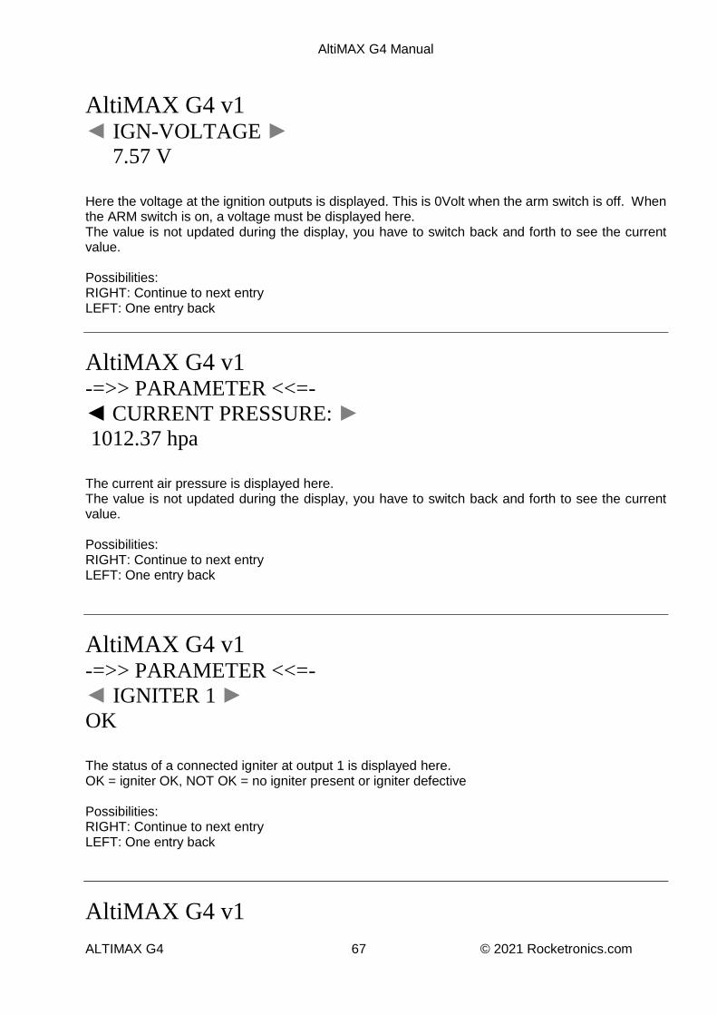
AltiMAX G4 Manual
ALTIMAX G4 67 © 2021 Rocketronics.com
AltiMAX G4 v1 ◄ IGN-VOLTAGE ►
7.57 V
Here the voltage at the ignition outputs is displayed. This is 0Volt when the arm switch is off. When the ARM switch is on, a voltage must be displayed here. The value is not updated during the display, you have to switch back and forth to see the current value. Possibilities: RIGHT: Continue to next entry LEFT: One entry back
AltiMAX G4 v1 -=>> PARAMETER <<=-
◄ CURRENT PRESSURE: ►
1012.37 hpa
The current air pressure is displayed here. The value is not updated during the display, you have to switch back and forth to see the current value. Possibilities: RIGHT: Continue to next entry LEFT: One entry back
AltiMAX G4 v1 -=>> PARAMETER <<=-
◄ IGNITER 1 ►
OK
The status of a connected igniter at output 1 is displayed here. OK = igniter OK, NOT OK = no igniter present or igniter defective Possibilities: RIGHT: Continue to next entry LEFT: One entry back
AltiMAX G4 v1
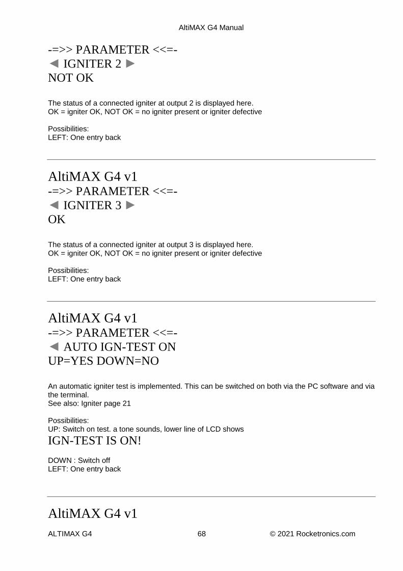
AltiMAX G4 Manual
ALTIMAX G4 68 © 2021 Rocketronics.com
-=>> PARAMETER <<=-
◄ IGNITER 2 ► NOT OK
The status of a connected igniter at output 2 is displayed here. OK = igniter OK, NOT OK = no igniter present or igniter defective Possibilities: LEFT: One entry back
AltiMAX G4 v1 -=>> PARAMETER <<=-
◄ IGNITER 3 ► OK
The status of a connected igniter at output 3 is displayed here. OK = igniter OK, NOT OK = no igniter present or igniter defective Possibilities: LEFT: One entry back
AltiMAX G4 v1 -=>> PARAMETER <<=-
◄ AUTO IGN-TEST ON
UP=YES DOWN=NO
An automatic igniter test is implemented. This can be switched on both via the PC software and via the terminal. See also: Igniter page 21 Possibilities: UP: Switch on test. a tone sounds, lower line of LCD shows
IGN-TEST IS ON! DOWN : Switch off LEFT: One entry back
AltiMAX G4 v1

AltiMAX G4 Manual
ALTIMAX G4 69 © 2021 Rocketronics.com
-=>> PARAMETER <<=-
◄ UNITS:
METRIC SI hpa/m ▲ Here the unit for the display of physical values can be changed, it is possible: Metric SI - Metric units, m for height, hpa for pressure Imperial - Imperial units as in the USA and England, inHg for pressure, ft for altitude. This setting only affects the display on the LCD terminal.
ATTENTION Always make sure that the settings made via the LCD terminal are also saved! There is no automatic saving!
AltiMAX G4 Manual
ALTIMAX G4 70 © 2021 Rocketronics.com
Disclaimer and warranty
The use of the ALTIMAX is at your own risk. The function of the ALTIMAX must always be
safeguarded by a safety system operating in a different way, for example a motor ejector or other
electronics.
The manufacturer is not liable for damages of any kind that occurred in any connection with the use
of the ALTIMAX, even to third parties.
The ALTIMAX is covered by a limited warranty of one year from the date of purchase, at the
discretion of the manufacturer. This expressly does not include damage that is the responsibility of
the user due to crashing or mishandling. Since the manufacturer has no influence on the handling of
the assembly, which contains electrostatically sensitive components, damage caused by ESD
(electrostatic discharge) is also excluded from the warranty. Free repair or replacement will only be
granted in case of obvious manufacturing defects,
I recommend to secure the use of the AltiMAX in the supersonic range by setting the Machdelay or to use here only the peak detection by the accelerometer. Triggering the barometric peak detection is only possible below Mach 0.7. Above this, it is blocked.

AltiMAX G4 Manual
ALTIMAX G4 71 © 2021 Rocketronics.com
Contact Manufacturer: Rocketronics.com Hugo Grotius St. 18 D-27404 Zeven GERMANY Email: [email protected]
Disposal This product must not be disposed of in the normal waste but must be taken to an official electronic waste collection point.