Embed Size (px)
Citation preview
8/12/2019 Alternative Approaches to Rear End Drag Reduction
http://slidepdf.com/reader/full/alternative-approaches-to-rear-end-drag-reduction 1/49
Alternative approaches to rear end drag reduction
Technical Report
Torbjörn Gustavsson
Stockholm 2006
KT! "epartment o# Aeronautical and $ehicle %ngineeringRo&al 'nstitute o# Technolog&
TR'TA(A$% 2006)*2
'SS+ *6,*(-660 .../kth/se
*

8/12/2019 Alternative Approaches to Rear End Drag Reduction
http://slidepdf.com/reader/full/alternative-approaches-to-rear-end-drag-reduction 2/49
PrefaceThis paper .as originall& #ormed during m& sta& at KT Startup#actor& in the autumn o#
200/ The intent o# that sta& .as originall& to make a commercial product out o# the patent 'received the same &ear/ The project turned into research and one result is this paper/
1or #urther inuires in the area ' can be reached b& e(mail) torbjorn3vorta#lo./com
Sincerel& &ours
Torbjörn Gustavsson
.../vorta#lo./com
Reaching #or the stars4
2

8/12/2019 Alternative Approaches to Rear End Drag Reduction
http://slidepdf.com/reader/full/alternative-approaches-to-rear-end-drag-reduction 3/49
AcknowledgementsAbove all ' .ould like to thank Kim +ouira #or his support during m& sta& at KT
Startup#actor&/
Second ' .ould like to thank all m& #riends and #amil&! especiall& m& brother and mother! #or
support and #eedback during development o# this project/
' also .ould like to thank 5ohn 7in at +ASA 7angle& Research entre .ho is the source o#
man& o# the reports ' used as re#erence material/ e has produced an ama8ing amount o# .ork
in ver& interesting areas and ' also .ould like to thank him #or providing some o# his material#ree o# charge/ ope#ull& ' .ill get the opportunit& to meet him some da&/
7ast but not least ' .ould like to thank Tomas 9elin and Arthur Ri88i at the "epartment o#
Aerod&namics at KT #or supporting the idea that the subject ' buried m&sel# so deep in could
end up in something else than just kno.ledge! that is this report/ :ithout them this .ork
.ould never have taken place/

8/12/2019 Alternative Approaches to Rear End Drag Reduction
http://slidepdf.com/reader/full/alternative-approaches-to-rear-end-drag-reduction 4/49
AbstractThis report begins .ith a short introduction to the problem o# aerod&namic drag #or
commercial vehicles/
The main subject is a surve& o# di##erent technologies available #or decreasing drag and
increasing per#ormance on blunt bodies and di##users/ 'nitiall& the .ork done b& +ASA on thearea o# boat(tailing a bus is overvie.ed/ A#ter that the #ocus turns to the oanda(e##ect and the
possibilit& to use it to improve per#ormance on trailers in the areas o# #uel consumption!
breaking and d&namic stabilit&/ ;oat(tail plates #inish up the studies per#ormed on commercial
road vehicles/
The interests then turn to alternative! unconventional approaches to reattach #lo. over a
back.ard #acing ramp/ ere are the use o# primaril& grooves and vorte< generators surve&ed/
The report ends .ith a closer look on the use o# micro vorte< generators on a (*0 aircra#t
and the drag reduction created/
=

8/12/2019 Alternative Approaches to Rear End Drag Reduction
http://slidepdf.com/reader/full/alternative-approaches-to-rear-end-drag-reduction 5/49
Table of Contents
1.NOMENCLATURE AND ARE!"AT"ON#.................................................................................................$
%."NTRODUCT"ON................................................................................................................................................&
'.D"((ERENT TEC)NOLO*"E#....................................................................................................................... +
/*/;>AT(TA'7'+G/////////////////////////////////////////////////////////////////////////////////////////////////////////////////////////////////////////////////////?3.1.1.Controlled boundary layers ................................................................................................................ 123.1.2.Aerodynamic boat-tail........................................................................................................................... 23
/2/GR>>$%S///////////////////////////////////////////////////////////////////////////////////////////////////////////////////////////////////////////////////////// 2-3.2.1.Transverse and swept grooves...............................................................................................................283.2.2.Longitudinal grooves.............................................................................................................................323.2.3.Passive porous surace.......................................................................................................................... 33
//$>RT%@ G%+%RAT>RS/////////////////////////////////////////////////////////////////////////////////////////////////////////////////////////////////////////=3.3.1.!ane-type vorte" generators..................................................................................................................3#3.3.2.$%eeler vorte" generators.....................................................................................................................3&3.3.3.'lunt body application o !orte" (enerators........................................................................................#1
,.CONT"NUED -OR....................................................................................................................................... ,$
/.CONCLU#"ON#.................................................................................................................................................,&
$.RE(ERENCE#................................................................................................................................................... ,0
,

8/12/2019 Alternative Approaches to Rear End Drag Reduction
http://slidepdf.com/reader/full/alternative-approaches-to-rear-end-drag-reduction 6/49
1. Nomenclature and abbreviations3" three dimensional
α angle o# attack in degrees
angle to.ard #reestream #lo.
δ boundar& la&er thicknessλ span.ise distance bet.een each geometric c&cle
∆ di##erence
BpC drop o# pie8ometric pressure over length ll
ρ air densit&a groove depth
b groove spacing
d drag coe##icient D 1"EFρH2 E2I
J momentum coe##icient D Fm$ jIEFSre# I
1" omputer 1luid "&namics
d $G spacing
d p pipe diameter"h hori8ontal o##set o# boat(tail plates divided b& the .idth o# the trailer
"v vertical o##set o# boat(tail plates divided b& the .idth o# the trailer
eE% non(dimensional device length
# #riction #actor! roughness and Re&nolds number dependent
GTR' Georgia Tech Research 'nstitute
% $G heightl $G length
ll pipe length
7 p boat(tail plate length divided b& the .idth o# the trailer
m air mass #lo.
air pressure #reestream d&namic pressureRe Re&nolds number
Sre# re#erence(E#ront( area
L mean velocit&
H #ree stream velocit& MmEsN
$ j isentropic airjet velocit&
$G vorte< generator
. truck .idth< distance
6

8/12/2019 Alternative Approaches to Rear End Drag Reduction
http://slidepdf.com/reader/full/alternative-approaches-to-rear-end-drag-reduction 7/49
2. IntroductionAerod&namic drag o# a commercial vehicle is a large part o# the vehicles #uel consumption!
according to ucho M*N it can contribute to as much as 60 O o# the vehicles #uel consumption/
So #ar aerod&namic design o# commercial vehicles has concentrated on the #ront end o# thevehicle/ Since it produces most drag it has been the most urgent part to optimise/ This
optimisation can easil& be spotted on trucks and tourist coaches/ The rear end con#iguration
has up until recentl& been neglected/ Gilhaus M2N ackno.ledge the #act that on tourist coaches
the rear end can contribute to as much as 2- O o# the over all drag/ This is the reason to .h&
the author has chosen to take a closer look at the di##erent technologies available to reduce
rear end drag/ 9uch o# this technolog& has its o##spring in aeroplane aerod&namics and thedesign o# di##users/
The main #ocus .ill be on tourist coaches since the& have a high average speed o# operation
and thus are more a##ected b& the aerod&namic drag/ All results given belo. can o# course be
applied to all kind o# vehicles such as trucks and other.ise blunt vehicles moving .ith highaverage speed/ ;ut the authors e<perience is that the market #or tourist coaches is more
openminded/
-

8/12/2019 Alternative Approaches to Rear End Drag Reduction
http://slidepdf.com/reader/full/alternative-approaches-to-rear-end-drag-reduction 8/49
3. Different technologies
3.1.Boat-tailing
The most common and natural .a& o# reducing rear end drag is boat(tailing! also called rear
end tapering/ 't o##ers a technolog& commonl& kno.n! .idel& used and .ith recognised e##ect/
;ut the practical application o# it is limited due to the #act that it greatl& reduces the com#ort
#or the passengers and loading capabilit&! see #igure */ Taking tapering to its drag reduction
possibilit& limits is not a realistic possibilit& o# practical reasons but it is still interesting tostud& the results o# such research since it could be used as a benchmark and goal #or other
studies/
(g2re 13 Effects of ta4erng t5e rear end of a to2rst coac5 617.
+asa MN per#ormed a series o# tests that suggest the use o# a truncated boat(tail/ :ith #ull(
scale tests the& achieved a drag coe##icient o# 0/02 .ith a #ull boat(tail F#igure 2I and a drag
coe##icient o# 0/0- .ith a truncated boat(tail F#igure I this .hen a bus .ithout a boat(tail hasa d o# 0/==,/ 't can also be compared to a rounded nose section that according to ;levins M=N
has d o# appro<imatel& 0/6 .hen Re&nolds number is P*0=/
(g2re %3 (2ll scale tests of a boat8tal at Nasa Dr9den. 6'7
?

8/12/2019 Alternative Approaches to Rear End Drag Reduction
http://slidepdf.com/reader/full/alternative-approaches-to-rear-end-drag-reduction 9/49
(g2re '3 (2ll scale tests of a tr2ncated boat8tal at Nasa Dr9den. 6'7
The truncation o# the boat(tail .as done at the natural point o# separation/ A less curved boat(tail .ould probabl& given larger di##erences bet.een a #ull boat(tail .ith #ull& attached #lo.
and a truncated boat(tail
Tests .ere per#ormed at speeds ranging up to 26 mEs FQ/6 kmEhI and corresponding Re&nolds
number ranged up to */*0-/ That includes the length o# both the vehicle and the boat(tail/
The general description o# vehicle used in tests is described in #igures = and ,/
(g2re ,3 Dmensons of t5e orgnal tr2ck wt5 s:2ared corners n meters ;nc5es<. 6/7
Q

8/12/2019 Alternative Approaches to Rear End Drag Reduction
http://slidepdf.com/reader/full/alternative-approaches-to-rear-end-drag-reduction 10/49
(g2re /3 Dmensons of f2ll and tr2ncated boat8tal. 6/7
Tests .ere per#ormed .ith #orebod&! hori8ontal and vertical corners rounded and a #aired and
sealed underbod&/ This to avoid separation o# air#lo. at the #ront end o# the vehicle and toma<imise the e##ect o# the boat(tail con#iguration compared to no boat(tail/
The results o# the test are compressed to #igure 6 and the& indicate that an average o# 2 O
drag reduction M,N .as attained .ith the #ull boat(tail compared to a blunt rear end/
*0

8/12/2019 Alternative Approaches to Rear End Drag Reduction
http://slidepdf.com/reader/full/alternative-approaches-to-rear-end-drag-reduction 11/49
(g2re $3 Aerod9namc drag =ers2s =e5cle =eloct9 for dfferent confg2ratons tested at Nasa Dr9den. 6/7
**

8/12/2019 Alternative Approaches to Rear End Drag Reduction
http://slidepdf.com/reader/full/alternative-approaches-to-rear-end-drag-reduction 12/49
3.1.1. Controlled boundary layers
Active separation control s&stem o# rear end #lo. can be per#ormed .ith tangential blo.ing as
suggested b& %nglar M6N! M-N among others/ The technolog& is also called the oanda %##ect
named b& enri oanda/ The idea is that a slo. air#lo. that generall& .ould separate over asur#ace is energi8ed .ith a high(velocit& #lo. and thus the #lo. becomes attached to a curved
sur#ace as sho.n b& #igure -/
(g2re &3 T5e Coanda effect demonstrated on a tralng edge. 6$7
This can also be balanced .ith the possibilit& to suction o# the boundar& la&er/ These t.o
technologies combined give the theoretical reduction o# =0 O in aerod&namic po.er/
The trailer con#iguration simulated at Georgia Tech Research 'nstitute FGTR'I is illustrated in#igure ?/ The main blo.ing slots are placed at each rear corners and one slot at the top leading
edge to avoid separation at the #ront end o# the trailer/
(g2re +3 T5e traler confg2raton sm2lated at t5e *eorga Tec5 Researc5 "nstt2te. 6$7
;lo.ing all rear slots could reduce spra& and drag and just blo.ing one slot at the rear control
the aerod&namic side #orces and thus give d&namic control to the vehicle/ This could #or
instance be used to increase li#t on the trailer and thus reduce rolling resistance and tire .ear/
'n the opposite .a& it is possible to increase do.n#orce on the trailer and provide breaking
assistance .hen needed and improve handling during slipper& conditions/ The e##ect o# .ind
gusts could be controlled and managed .ith such a s&stem and reduce the risk o# jack(kni#ing/
As a source o# air#lo. GTR' suggested a second turbo generator/ This to reduce in#luence o#
engine per#ormance that other.ise .ould be adverse using bleed o# e<isting turbo pressure or
engine e<hausts directl&/
Hsing a secondar& turbo it is necessar& to channel the air #rom the engine compartment to therear o# the trailer/ 'n the case o# a standard trailer .e assume the length o# - m #or the trailer
*2

8/12/2019 Alternative Approaches to Rear End Drag Reduction
http://slidepdf.com/reader/full/alternative-approaches-to-rear-end-drag-reduction 13/49
and the thickness o# the .alls limit the diameter o# the tubes #rom the e<tra turbo to the rear o# the truck to a diameter o# appro<imatel& 0/* m/ :ith housing #rom the e<tra turbo mounted on
the trucks e<haust s&stem it .ould give an overall length o# the tubing o# appro<imatel& *0 m/
;& assuming airspeed o# 0 mEs in the tubes and a #riction #actor o# 0/00*, F#ig -/2 M?NI and
using euation -/* #rom 9asse& M?N .e get a pressure drop o#)
Pad
ul p
g d
ul
g
p
p
l
p
l ,**!0
0*000*,!0222,!*2C
2
=C 2
22
=⋅⋅⋅⋅
=⋅⋅⋅⋅
=∆⇒⋅⋅
⋅⋅⋅=
⋅
∆ ρ
ρ F*I
This does not include losses #rom couplings and bends and similar since the #ormula is used#or long! unobstructed! straight pipes so the loss can be considered to be even higher/ A
lo.er airspeed reduces pressure loss/ Another problem using bleeding o# turbopressure is that
the pressure might not be available .hen breaking and turning since the engine is running
under lo. revs and not generating #ull pressure/ A solution might be to add another tank o# air
under pressure generated b& the compressor to guarantee airsuppl& under all conditions/
1or .ind(tunnel tests GTR' used a model described b& #igure Q/
(g2re 03 *TR" wnd t2nnel model s a generc descr4ton of a tractor8traler confg2raton. 6$7
The GTR' .ind(tunnel model has a suare section area o# 0/? m2 F*2Q0 s/ in/I and the si8e
o# the model is a 0/06,(scale model o# a truck that produced a ,/* O .ind(tunnel blockage/The Re&nolds number based on trailer length .as */Q*06 at H D * mEs F-0 mphI or /Q*06 at
tunnel ma<imum speed/
1igure *0 sho. the possibilit& in drag reduction #or a 2Q/,(ton F6, 000 poundI *?(.heel
tractor(trailer rig .ith a #rontal area o# *0 m2 F*0-/, s/ #t/I/
*

8/12/2019 Alternative Approaches to Rear End Drag Reduction
http://slidepdf.com/reader/full/alternative-approaches-to-rear-end-drag-reduction 14/49
(g2re 1>3 Drag red2ctons d2e to blown bo2ndar9 la9ers as s2ggested b9 *TR". T5e 244er c2r=es
re4resentng total 5orse4ower re:2red at t5e w5eels to o=ercome all forces 4resent. 6$7
At a speed o# * mEs F-0 mphI! po.er reuired to overcome drag and rolling resistance can be
reduced b& 2= respectivel& 2 O as suggested b& 1igure *0/
+avier(Stokes euation based omputational 1luid "&namics anal&sis .as per#ormed at
Georgia Tech School o# Aerospace %ngineering/ "i##erences in predicted #lo. are presented
in #igures **a and b/
(g2re 11;a8b<3 C(D 4redctons of 2nblown and blown bo2ndar9 la9er 4erformed at *eorga Tec5
#c5ool of Aeros4ace Engneerng. T5e reattac5ment of t5e flow clearl9 ndcates t5e 4ossblt9 to red2ce
base8drag of c2rrent confg2raton. 6$7
*=

8/12/2019 Alternative Approaches to Rear End Drag Reduction
http://slidepdf.com/reader/full/alternative-approaches-to-rear-end-drag-reduction 15/49
GTR' manage to sho. through .ind(tunnel test on the model described above that d isreduced b& ? O just b& rounding the leading edge o# the trailer/ '# the a#t edges are rounded the
drag reduction is o# magnitude - O and that is .ithout blo.ing o# the boundar& la&er/ These
simple steps add up to a drag reduction o# *, O .itch clearl& is a simple .a& to reduced #uel
consumption/ This is o# course .hen #airing o# the tractor(trailer gap is per#ormed/ :ithout
closing o# the gap bet.een the tractor and the trailer the drag increases dramaticall&!especiall& in side(.ind conditions/
As #igure *2 depicts there can be major gains in blo.ing the trailing edges o# a trailer/ The
bene#its o# the technolog& is o# course at is best .hen per#ormed on all #our sides/ The tests
.ere per#ormed at .ind(tunnel speeds o# * mEs F-0 mphI! d&namic pressure o# ? a F**/?6
ps#I and Re&nolds number o# 2/,**06 based on total length/ At some conditions a ,0 O drag
reduction .as measured .hen using blo.n boundar& la&ers/
(g2re 1%3 Drag red2cton w5en blowng dfferent rear tralng edges at tests 4erformed at *TR". 6&7
"uring some speci#ic conditions! blo.ing over top and bottom slot onl&! drag increased/ This
could be! as mentioned earlier! be use#ul .hen breaking the truck/
Some con#igurations .ith blo.n boundar& la&ers and sealed #airing bet.een tractor and trailer sho. such small values o# d as some sports cars in the range o# 0// This is then .hen the
*,

8/12/2019 Alternative Approaches to Rear End Drag Reduction
http://slidepdf.com/reader/full/alternative-approaches-to-rear-end-drag-reduction 16/49
tractor still is missing several realit& bits such as engine cooling intake! mirrors! roughunderbod& and bod& component mounting mismatches/ :hen all o# these come into pla& .e
can e<pect d to rise to normal values once again/ ;ut it is an e<ample o# .hat the
technolog& could be able to do in the #uture .hen more care#ul manu#acturing methods and
attention to details and aerod&namic drag is deplo&ed/
9easurements o# li#t varied .ith di##erent slot blo.ing con#igurations as can be seen in #igure*/ These ualities can be used to decrease rolling resistance or increase .heel pressure to
reduce breaking distances/
(g2re 1'3 Tests at *TR" s5ow t5at t s 4ossble to 2se tangental blowng as a wa9 to ncrease or decreaselft on t5e traler. 6&7
/ 1erraresi MQN per#ormed in cooperation .ith Scania A; a series o# 1" tests based on a
simple truck model consisting o# a prism .ith rounded edges and .ithout .heels/ omparison
.as made .ith a .ind(tunnel model based on the eps con#iguration .ith the $olvo .ind(
tunnel as re#erence/ The eps con#iguration is an aerod&namical ideal truck(trailer
combination .ith ,/ m length! */ m .idth and 2 m height/
*6

8/12/2019 Alternative Approaches to Rear End Drag Reduction
http://slidepdf.com/reader/full/alternative-approaches-to-rear-end-drag-reduction 17/49
At a simulated velocit& o# ==/= mEs and a re#erence #rontal area o# */ m2! onl& hal# o# thetruck .as modelled due to s&mmetr& reasons! the results suggests a 2Q O reduction in drag
.ithout blo.ing the boundar& la&ers as table 2 sho. and the di##erent con#igurations tested is
sho.n in #igure *=/
Truck con#iguration d Reduction;asic 0/26
;oat(tail! lt D 0/,!ϕ D *,° 0/2 2Q O
;oat(tail! lt D 0/2,!ϕ D *,° 0/2-* *- O
;oat(tail! lt D 0/*!ϕ D *,° 0/2?, *2 O
Round! radius D 0/* m 0/2Q *0 ORound! radius D 0/2 m 0/2? *= O
Table 13 Res2lt for C(D calc2latons at T). Red2ctons n drag are clear and t5s s wt5o2t blowng of
t5e bo2ndar9 la9ers w5ere lt ? tal lengt5 6m7 and ϕ ?tal angle. 607
(g2re 1,3 Dfferent confg2ratons sm2lated at T). 607
1igure *, present a reduction in drag #or the rounded section as the radius increase/
(g2re 1/3 Cd =ers2s rear end ro2ndng rad2s. 607
*-
8/12/2019 Alternative Approaches to Rear End Drag Reduction
http://slidepdf.com/reader/full/alternative-approaches-to-rear-end-drag-reduction 18/49
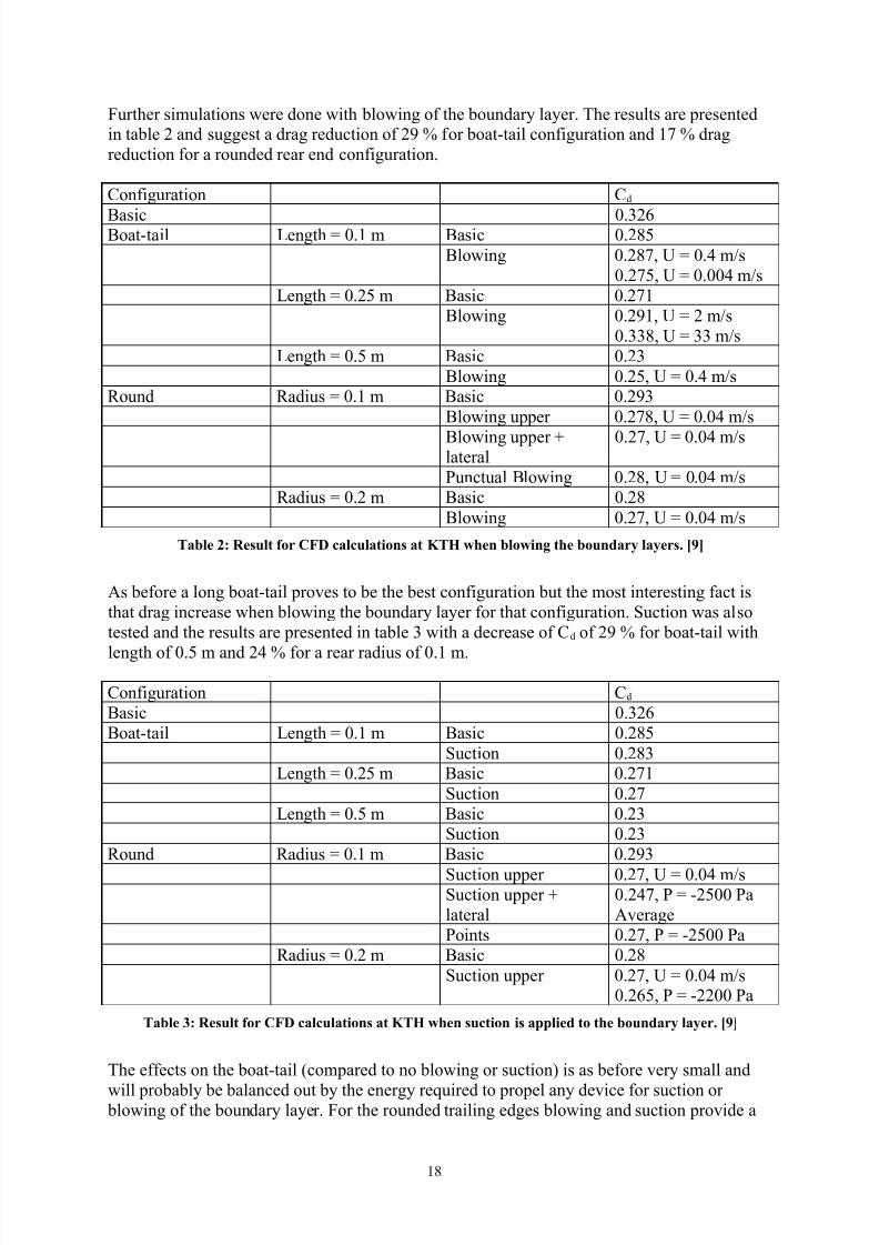
1urther simulations .ere done .ith blo.ing o# the boundar& la&er/ The results are presentedin table 2 and suggest a drag reduction o# 2Q O #or boat(tail con#iguration and *- O drag
reduction #or a rounded rear end con#iguration/
on#iguration d
;asic 0/26;oat(tail 7ength D 0/* m ;asic 0/2?,
;lo.ing 0/2?-! H D 0/= mEs
0/2-,! H D 0/00= mEs
7ength D 0/2, m ;asic 0/2-*
;lo.ing 0/2Q*! H D 2 mEs
0/?! H D mEs
7ength D 0/, m ;asic 0/2
;lo.ing 0/2,! H D 0/= mEsRound Radius D 0/* m ;asic 0/2Q
;lo.ing upper 0/2-?! H D 0/0= mEs
;lo.ing upper lateral
0/2-! H D 0/0= mEs
unctual ;lo.ing 0/2?! H D 0/0= mEs
Radius D 0/2 m ;asic 0/2?
;lo.ing 0/2-! H D 0/0= mEs
Table %3 Res2lt for C(D calc2latons at T) w5en blowng t5e bo2ndar9 la9ers. 607
As be#ore a long boat(tail proves to be the best con#iguration but the most interesting #act is
that drag increase .hen blo.ing the boundar& la&er #or that con#iguration/ Suction .as also
tested and the results are presented in table .ith a decrease o# d o# 2Q O #or boat(tail .ith
length o# 0/, m and 2= O #or a rear radius o# 0/* m/
on#iguration d
;asic 0/26
;oat(tail 7ength D 0/* m ;asic 0/2?,
Suction 0/2?7ength D 0/2, m ;asic 0/2-*
Suction 0/2-
7ength D 0/, m ;asic 0/2
Suction 0/2
Round Radius D 0/* m ;asic 0/2Q
Suction upper 0/2-! H D 0/0= mEsSuction upper
lateral
0/2=-! D (2,00 a
Average
oints 0/2-! D (2,00 a
Radius D 0/2 m ;asic 0/2?
Suction upper 0/2-! H D 0/0= mEs0/26,! D (2200 a
Table '3 Res2lt for C(D calc2latons at T) w5en s2cton s a44led to t5e bo2ndar9 la9er. 607
The e##ects on the boat(tail Fcompared to no blo.ing or suctionI is as be#ore ver& small and
.ill probabl& be balanced out b& the energ& reuired to propel an& device #or suction or blo.ing o# the boundar& la&er/ 1or the rounded trailing edges blo.ing and suction provide a
*?

8/12/2019 Alternative Approaches to Rear End Drag Reduction
http://slidepdf.com/reader/full/alternative-approaches-to-rear-end-drag-reduction 19/49
clear di##erence in per#ormance/ Since rounding o# the edges is more bene#icial consideringspacing #or passengers and load FcargoI it might be interesting to #urther investigate this
techniue/
;enjamin 7e Rou< M*0N per#ormed a series o# hal#(scale tests at the 9'RA .ind(tunnel in
%ngland/ The tests .ere per#ormed on the %S hal#(scale model at air speeds o# 2?/= mEs dueto structural limitations o# the model/ The measurements o# the model is)
• 7ength D ,/ m
• :idth D */ m
• eight D 2 m
That give a re#erence F#rontalI area o# Sre# D 2/= m2/
The overall con#iguration o# the model is presented in #igure *6 .here the air intake! pump
and jet device in pointed out/ Scale is not respected in the dra.ing but should be considered a
schematic/ The jet device is closer described in #igure *-/
(g2re 1$3 O=erall =ew of t5e test model PEP#. 61>7
*Q

8/12/2019 Alternative Approaches to Rear End Drag Reduction
http://slidepdf.com/reader/full/alternative-approaches-to-rear-end-drag-reduction 20/49
(g2re 1&3 @et de=ces secton wt5 a tal and 4ress2re ta4s. 61>7
The jet device cover the circum#erence o# the a#t o# the truck and the air outlet is just belo.
the S in #igure *-/ This gives the tangential blo.ing that is investigated/ 'n order to maintain
a stead& #lo. the volume be#ore the outlet is large and .ork as a plenum to eual outdi##erences in pressure/
The tail section is de#ined b& #igure *? and their variations during the tests are accounted #or
in table =/
(g2r 1+3 Tal secton. L18 (lat eBtenson of t5e traler to st2d9 t5e effect of t5e locaton of t5e et from t5e
t2rnng s2rface. R8 Rad2s of t5e ro2nded 4art. α8 Angle of t5e ro2nded 4art. L%8 (lat 4art as a boat8tal.
61>7
20

8/12/2019 Alternative Approaches to Rear End Drag Reduction
http://slidepdf.com/reader/full/alternative-approaches-to-rear-end-drag-reduction 21/49
Table ,3 !aratons of tal 4arameters d2rng t5e M"RA tests. 61>7
The length and height o# the tail is given b& #ormulas 2 and
IcosFIsinF 2* αα ⋅+⋅+= L ) L Ltail F2I
IsinFIIcosF*F 2 αα ⋅+−⋅= L ) * tail FI
The #irst aim o# the e<periments .as to determine the best tail con#igurations/ This .as doneusing a mm slot .ith blo.n and non(blo.n boundar& la&ers to determine .hich
con#iguration .as most bene#icial/ 1igure *? sho. the di##erent con#igurations tested and
table , present the results/
2*

8/12/2019 Alternative Approaches to Rear End Drag Reduction
http://slidepdf.com/reader/full/alternative-approaches-to-rear-end-drag-reduction 22/49
(g2re 103 Dfferent tal confg2ratons tested at t5e M"RA wnd8t2nnel. 61>7
+ame ,escription C d wit%out
blowing
C d wit%ma"imum
blowing
∆C d points
/positive or decreasing drag0
;aseline 0!== 0!=? (=T2 Rounded 0!=- 0!? QT Rounded 0!=6 0!Q -T= Rounded 0!=0 0!=0 0T, Rounded 0!=* 0!2 QT6 9i<ed 0!=, 0!=6 (*
T- ;oat(tail 0!*2 0!0* **T? ;oat(tail 0!=0 0!*= 26TQ ;oat(tail 0!,- 0!6, (?T'0 9i<ed 0!,Q 0!=? **T** 9i<ed 0!== 0!=2 2T *2 9i<ed 0!= 0!=- (=T* 9i<ed 0!=- 0!,0 (T *= 9i<ed 0!=, 0!,2 (-
Table /3 Test res2lts from M"RA wt5 and wt5o2t blowng of t5e bo2ndar9 la9ers. 61>7
22
8/12/2019 Alternative Approaches to Rear End Drag Reduction
http://slidepdf.com/reader/full/alternative-approaches-to-rear-end-drag-reduction 23/49
't is clearl& seen that con#igurations - and ? are those .ho present the lo.est drag and largestdi##erence in d/ omparison bet.een the tails ! ** and *2 sho.s that increased length o# 7*
is not bene#icial #or drag reduction/
Tail number , sho. that there is no point in e<tending the tail be&ond the point o# separation!
on the contrar&! a prolonged tail be&ond that point increase drag/ So it .ould be interesting to#ind the point o# separation and thus optimise tail length/ ;ut all these values are lo.compared to the ones achieved .hen using boat(tails and that con#iguration is to pre#er/
The most bene#icial con#iguration .ould be the *,° tail as con#irmed b& other tests at other
times and as is sho.n b& table ,/ 1urther investigation o# tail ? .as done since it in an earl&
stage sho.ed the highest drag drop/ "i##erent blo. ratios and slot heights .ere tested and the
slot height o# * mm seems to be the most e##icient/ This might not directl& be trans#erred to a
#ull(scale model so in that case optimal slot height must be #ound/
The po.er savings on this devise .as about 20 O compared to the re#erence values and .as
achieved as earlier mentioned .ith tail ? and ma<imum blo.ing/
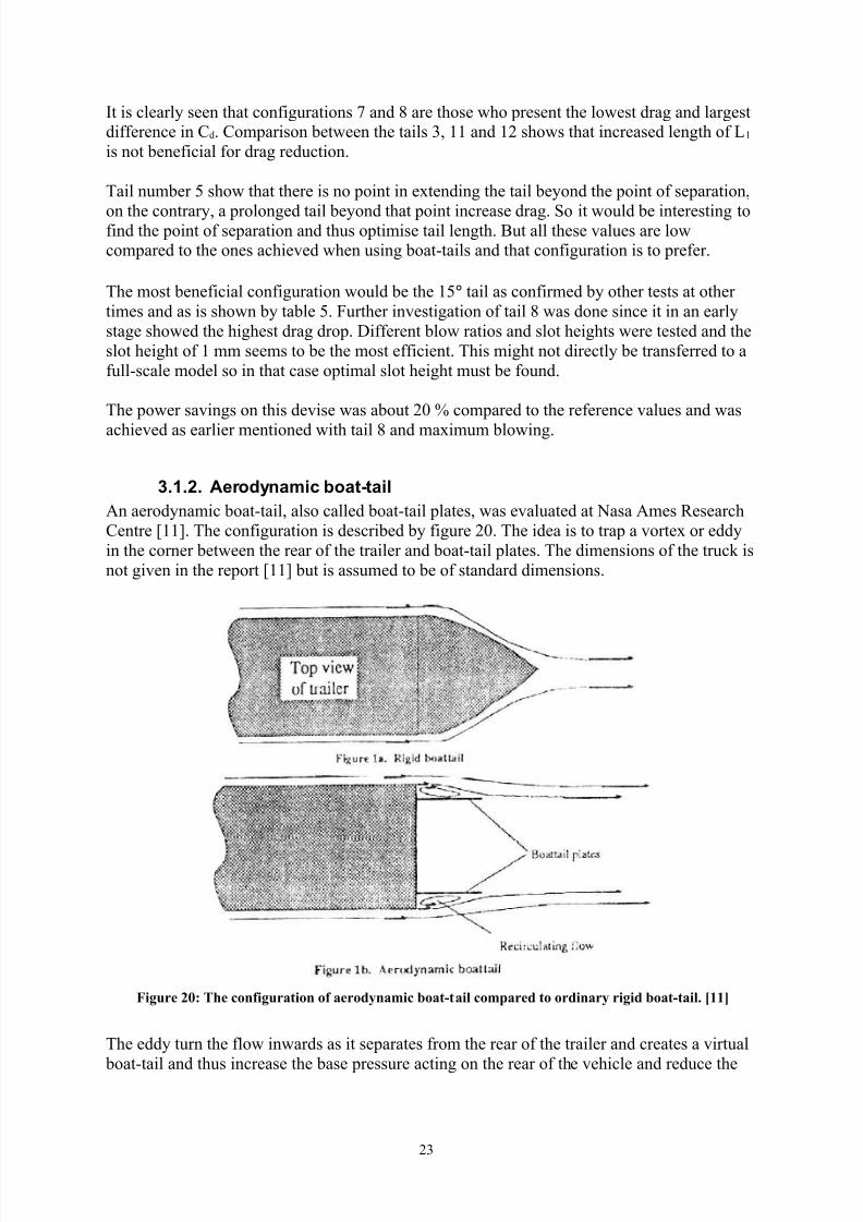
3.1.2. Aerodynamic boat-tail
An aerod&namic boat(tail! also called boat(tail plates! .as evaluated at +asa Ames Research
entre M**N/ The con#iguration is described b& #igure 20/ The idea is to trap a vorte< or edd&
in the corner bet.een the rear o# the trailer and boat(tail plates/ The dimensions o# the truck is
not given in the report M**N but is assumed to be o# standard dimensions/
(g2re %>3 T5e confg2raton of aerod9namc boat8tal com4ared to ordnar9 rgd boat8tal. 6117
The edd& turn the #lo. in.ards as it separates #rom the rear o# the trailer and creates a virtual
boat(tail and thus increase the base pressure acting on the rear o# the vehicle and reduce the
2

8/12/2019 Alternative Approaches to Rear End Drag Reduction
http://slidepdf.com/reader/full/alternative-approaches-to-rear-end-drag-reduction 24/49
net aerod&namic drag o# the vehicle/ 1igure 2* sho. the aerod&namic boat(tail mounted onthe rear end o# the truck/
(g2re %13 T5e rear end confg2raton of t5e traler w5en 4erformed wnd8t2nnel tests accordng to
Lanser et. al. at t5e Nasa Ames Researc5 Centre. 6117
Table 6 sho. the di##erent geometrical con#igurations tested/
7 "$ "h
0/0 0!0 0!0
0/2= 0/0= 0!0=
0!2= 0/06 0/06
0/2= 0/*2 0/*2
0/0 0/0= 0!0=
0/0 0!06 0/06
0/0 0!0Q 0/0Q
0/0 0/0= 0/06
0!0 0/06 0/0Q
0/6 0/0= 0!0=0/6 0!06 0!06
0/6 0/*2 0/*2
0/6 0/*, 0/*,
0/6 0/0= 0!06
0/== 0/0= 0/0=
0/== 0/06 0/06
0/== 0/0Q 0/0Q
Table $3 Dfferent confg2ratons tested at t5e Nasa Ames Researc5 Centre 2sng t5e aerod9namc boat8tal descrbed n (g2re %1. All lengt5s and dstances are normalsed b9 t5e traler wdt5. 6117
2=

8/12/2019 Alternative Approaches to Rear End Drag Reduction
http://slidepdf.com/reader/full/alternative-approaches-to-rear-end-drag-reduction 25/49
'n #igure 22 a(b the pressure distribution across the rear doors o# the truck at &a. angles 0 and
± 6° are presented/ 't clearl& sho.n F#igure 22 bI that the pressure inside the aerod&namic
boat(tail has increased/ The ma<imal ∆d .as received .hen hori8ontal and vertical o##set
F"h! "vI .as 0/06. F. D truck .idthI and 7 p D 0/6/
(g2re %%;a8b<3 Press2re dstrb2ton o=er t5e centre of t5e rear doors for t5e baselne and o4tm2m
confg2raton. 6117
d data .ere obtained at a velocit& o# 2, mEs F,? milesEhourI/ The device consistentl& sho.eddrag reductions in the range o# *0 O but it .as also sensitive to &a. angle as #igure 2 sho./
2,

8/12/2019 Alternative Approaches to Rear End Drag Reduction
http://slidepdf.com/reader/full/alternative-approaches-to-rear-end-drag-reduction 26/49
(g2re %'3 C5ange n drag as a f2ncton of 9aw angle w5en o4tm2m aerod9namc boat8tal s mo2nted.C
Dref s t5e orgnal C
d of t5e tr2ck wt5 no aerod9namc de=se mo2nted at t5e rear. 6117
26

8/12/2019 Alternative Approaches to Rear End Drag Reduction
http://slidepdf.com/reader/full/alternative-approaches-to-rear-end-drag-reduction 27/49
3.2.Grooves
Another technolog& developed b& 5// 7in et/ al/ M*2N but originating in the Soviet Hnion is
the use o# transverse and s.ept grooves/ The .ork .as per#ormed on a di##user but should be
applicable on other areas too/ Some ,0 O drag reduction has been reported on blu## bodies.ith grooves/
5// 7in et/ al/ per#ormed their tests at a Re&nolds number o# ,/**06 at +ASA 7angle& ,* <
-* cm tunnel! that is a lo.(turbulence! subsonic! open(circuit tunnel/ Tests .ere per#ormed at
#ree(stream velocit& o# =0/2 mEs/ 1igure 2= describes the test con#iguration used/ A suction
slot .as installed in #ront o# the test section to remove an& upstream in#luence on the testsection/ The ceiling o# the tunnel above the test section .as adjusted in a .a& to ensure a 8ero
pressure gradient/
(g2re %,3 T5e test confg2raton at NA#A Langle9 wnd8t2nnel 4erformng test of groo=es o=er abackward8facng ram4. 61%7
The boundar& la&er just ahead o# the separation ramp .as #ull& turbulent and appro<imatel&
/2, cm in thickness/ The shoulder radius o# the ramp .as 20/ cm F? in/I and the ramp .as at
a 2,U as sho.n b& #igure 2=/ The .idth o# the test section .as to #ull .ind(tunnel .idth o# -*
cm/
The #lo. separated at appro<imatel& the midpoint o# the ramp .ithout the grooves/ The
grooves .ere placed on the shoulder o# the ramp and di##erent geometries tested are presented
in #igure 2,/
2-

8/12/2019 Alternative Approaches to Rear End Drag Reduction
http://slidepdf.com/reader/full/alternative-approaches-to-rear-end-drag-reduction 28/49
3.2.1. Transverse and se!t grooves
(g2re %/3 Dfferent test geometr9 at NA#A Langle9 wnd8t2nnel 4erformng tests of groo=es o=er a
backward8facng ram4. 61%7
ressure taps registered the pressure distribution on the ramp and the #loor do.nstream o# the
ramp/ The results are presented in #igure 26 and sho. acceleration and a s&mmetric
deceleration .hen air #lo.s around a cornerV this is the reason #or the pressure drop on theupstream portion o# the shoulder/
(g2re %$3 Press2re dstrb2ton of t5e backward8facng ram4. 61%7
To illustrate #lo. separation oil #lo. .as used/ Some o# the results are presented in #igures 2-
and 2?/
2?

8/12/2019 Alternative Approaches to Rear End Drag Reduction
http://slidepdf.com/reader/full/alternative-approaches-to-rear-end-drag-reduction 29/49
(g2re %&3 Ol flow o=er dfferent ram4 models were a< s t5e reference model and b< t5e model wt5
trans=erse groo=es. 61%7
(g2re %+3 Ol flow o=er dfferent ram4 models w5ere a< 5as longt2dnal groo=es and b< 5a=e ,/ degreeswe4t groo=es. 61%7
An optimum placement #or transverse grooves proved to be to begin .ith the grooves one
boundar&(la&er thickness upstream o# the base model separation line and e<tending one
boundar&(la&er thickness do.nstream o# the separation line/ This con#iguration reduced thedistance #rom separation to reattachment b& 20 O/ The most e##ective con#iguration proved to
have a depth(to(.idth ratio FaEbI o# 2/6-/ Reduction o# depth(to(.idth ratio reduced
e##ectiveness o# the device/
2Q

8/12/2019 Alternative Approaches to Rear End Drag Reduction
http://slidepdf.com/reader/full/alternative-approaches-to-rear-end-drag-reduction 30/49
Hsing longitudinal and =, degree s.ept grooves the depth FaI varied along each groove! #rom8ero depth at the leading edge to about 0/6= cm at the midpoint/ Since the pressure recover&
F#igure 26I is not as large using =,(degree grooves as using transverse .e have an adverse
result using the =,(degree grooves compared to baseline con#iguration/ This could be
e<plained b& the same phenomenon as #or transverse groves .ith depth(to(.idth ratio o# */*=V
the distance bet.een the grooves is too small and the air#lo. e<periences it as a closed cavit&and thus there is no reduction in reattachment distance Fthe distance #rom re#erence separationline to ma<imum pressure coe##icientI/
The mechanism associated .ith di##erent improvements in pressure recover& and reduction in
reattachment distance is #or the transverse grooves a roller bearing mechanism that can be
e<plained in such .a& that the air rolls or rotates in each individual groove/ 1or the
longitudinal grooves it could be the techniue o# partial boat(tailing/
5/ / 7in et al M*N per#ormed another series o# tests that included man& more di##erent
methods to improve pressure recover& on a back.ard #acing ramp/ The tests per#ormed at
+ASA 7angle& M*N .ere per#ormed at the same tunnel and same con#iguration as the tests.ith grooves described above M*2N/ The di##erent test con#igurations are illustrated b& #igure
2Q a(d/
0

8/12/2019 Alternative Approaches to Rear End Drag Reduction
http://slidepdf.com/reader/full/alternative-approaches-to-rear-end-drag-reduction 31/49
(g2re %0 ;a8d<3 *eometr9 of se4araton control de=ces. 61'7
*

8/12/2019 Alternative Approaches to Rear End Drag Reduction
http://slidepdf.com/reader/full/alternative-approaches-to-rear-end-drag-reduction 32/49
'n contrar& to .hat is said be#ore M*2N it is no. stated M*N that a correct design o# s.eptgrooves probabl& .ill be more e##icient than transversal grooves/ That is #ounded on #act that
there is a three(dimensional #lo. generated b& the transversal grooves that is sho.n in #igure
2- and this is .hat generate the bene#icial #lo./ A proper design o# s.ept grooves .ould
rein#orce this behaviour and possibl& generate a reduction in reattachment distance/
>ptimum transverse con#iguration described b& #igure 0! .here aEb D 2/6-! reduced thedistance to reattachment b& almost ,0 O/
(g2re '>3 Press2re dstrb2tons for trans=erse groo=es. 61'7
3.2.2. "ongitudinal grooves
1igure 2Q c sho. the di##erent longitudinal grooves that .ere tested/ 1igures * sho. the pressure distribution using the di##erent grooves/
(g2re '13 Press2re dstrb2ton for longt2dnal groo=es wt5 %8nc5 s4acng. 61'7
A separation o# ,0!? mm F2 inchesI bet.een each groove proved to be most e##icient spacingthat .ere testedV it signi#icantl& reduced the distance to reattachment/ As #igure * sho. the
2

8/12/2019 Alternative Approaches to Rear End Drag Reduction
http://slidepdf.com/reader/full/alternative-approaches-to-rear-end-drag-reduction 33/49
short $(grooves proved to be the most e##icient con#iguration under these tests and it reducedthe reattachment distance b& 66 O/ :orth mentioning can be that WshortX(! WlongX( and sine(
.ave grooves had a shorter reattachment distance than the smaller 8ero(s.eep angle
longitudinal grooves mentioned earlier M*2N/ 1or a *00 mm F= inchI distance bet.een the
grooves the sine(.ave con#iguration proved to be more e##icient/
3.2.3. #assive !orous surface
This technolog& has its background in drag reduction on trans( and super(sonic .ings/ "rag
reduction is achieved b& placing a thin cavit& .ith porous sur#ace .here the shock .ave islocated/ The higher pressure behind the shock.ave circulates the air through the cavit& to the
lo.er pressure ahead o# the shock/ This e##ects both boundar&(la&er separation and entrop& in
a positive .a&/
The techniues tested are described in #igure 2Q b/ A #ull& porous sur#ace has little or no
positive e##ect on the pressure distribution/ ;ut a non(porous sur#ace separating a porous
sur#ace do.nstream and tangential blo.ing slot upstream has some positive on pressuredistribution as illustrated b& #igure 2/
(g2re '%3 Press2re dstrb2ton for 4ass=e tangental blowng. 61'7
The most bene#icial con#iguration is .hen the 0/? mm F0/02(inchI tangential gap is placed at
the baseline separation location Flocation in #igure 2I/ The problems .ith the techniue
Fpressure driven sel#(bleedingI are probabl& due to insu##icient mass #lo. but the technolog&might have applications #or more severel& separated cases .ith larger adverse pressure
gradients/

8/12/2019 Alternative Approaches to Rear End Drag Reduction
http://slidepdf.com/reader/full/alternative-approaches-to-rear-end-drag-reduction 34/49
3.3.Vortex generators
$orte< generators have normall& been used to increase lo. speed! high angle per#ormance on
aircra#t and to reattach separated #lo. on air#oils/ >n a #lap de#lection o# ,° 7in et/ al/ M*=N
managed to reattach the air#lo. completel&/
:heeler vorte< generators have in commercial tests .ithin the trucking industr& M*Nindicated up to *0 O #uel mileage improvement/
:hen per#orming tests at the +ASA 7angle& .ind tunnel M*N! to be able to measure the drag
o# the vorte< generators a balance .as used/ A ie8oresistive de#lection sensor .as used to
convert displacement into drag #orce/ The range o# the balance .as 0 Y ?/Q ka F0 Y */ lb#I.ith a resolution o# */, a F2/2*0(= lb#/I The measurement o# the drag .as conducted .ith
vorte< generators placed *,2 mm F6 inchesI and *06- mm F=2 inchesI upstream o# the
separation ramp described in #igure 2=/
3.3.1. $ane-ty!e vorte% generators
>ne(inch(high vane(t&pe counter rotating vorte< generators as described b& #igure 2Q d .as
initiall& tested and it provided attached #lo. directl& do.nstream the generators/ :hen moved
#rom ,δ F*6 cmI to *,δ F=Q cmI upstream o# the baseline separation line the generators
maintained their e##icienc&/ 1igure sho. three span.ise pressure distributions at 0! λE= and
λE2 distance a.a& #rom the device centreline/
(g2re ''3 Press2re dstrb2ton for 18nc585g5 co2nter8rotatng =orteB generators at /d 24stream of t5e
baselne se4araton. 61'7
1igure also sho. an improved pressure recover& but also a reduction o# pressure on rampsshoulder region/ This is desirable i# one .ants to increase li#t but result in a pressure drag
penalt&/ The reduction in pressure is caused b& increase in local velocit& resulting #rom the
redirection o# high momentum air#lo. #rom outer parts o# boundar& la&er/
=

8/12/2019 Alternative Approaches to Rear End Drag Reduction
http://slidepdf.com/reader/full/alternative-approaches-to-rear-end-drag-reduction 35/49
3.3.2. &heeler vorte% generators
The con#iguration .ith :heeler generators is illustrated b& #igure 2Q d/
1lo. visualisations #or the :heeler vorte< generators sho. that the optimal placement is justahead o# the hori8ontal tangential location on the shoulder o# the separation ramp/ >il #lo.
visualisations indicate that both *2!,( and ( mm FZ( and *E?( inchI high generators! .hen placed at the optimum location! are e##icient and reduce reattachment distance up to 66 O/
1igure = a and b sho. pressure distributions #or di##erent span.ise location o# pressure taps/
1igure = a #or the *2!, mm high generators and #igure = b #or the mm high generators/
The variations are much smaller than #or the vane(t&pe generators and the mm :heeler generators produce virtuall& no di##erence in pressure distribution span.ise/
(g2re ',;a8b<3 Press2re dstrb2tons for -5eeler =orteB generators. 61'7
,

8/12/2019 Alternative Approaches to Rear End Drag Reduction
http://slidepdf.com/reader/full/alternative-approaches-to-rear-end-drag-reduction 36/49
Since the :heeler vorte< generators produce less three(dimensional #lo.! indicated b& thelack o# variation in pressure distribution span.ise! it minimise pressure reduction at the
shoulder o# the ramp and thus is more bene#icial #or pressure(drag reduction/
The bene#icial behaviour o# the lo. :heeler generators is because the turbulent velocit&
pro#ile o# the boundar& la&er as described b& #igure ,/
(g2re '/3 Locaton 5eg5t to bo2ndar9 la9er 4rofle. 61'7
At device heights o# 0/2 δ the local velocit& is over -, O o# the #ree(stream value and #urther increase in height onl& give minor addition to air speed/
5// 7in summarised the results M*,N in #igure 6 and illustrate the baseline con#iguration
separation compared to the con#igurations .ith $G using oil#lo. as sho.n in #igure - a(c/
6

8/12/2019 Alternative Approaches to Rear End Drag Reduction
http://slidepdf.com/reader/full/alternative-approaches-to-rear-end-drag-reduction 37/49
(g2re '$;a8b<3 Relat=e effect=eness n flow se4araton control =ers2s de=ce categor9. 61/7
-

8/12/2019 Alternative Approaches to Rear End Drag Reduction
http://slidepdf.com/reader/full/alternative-approaches-to-rear-end-drag-reduction 38/49
(g2re '&;a8c<3 Ol8flow demonstratng t5e effect of dfferent confg2ratons. a< T5e baselne
confg2raton. b< >.+ 85g5 =ane8t94e co2nter8rotatng !*s at $ 5 24stream of baselne se4araton. c< >.% 85g5 =ane8t94e co2nter8rotatng !*s at 1> 5 24stream of bo2ndar9 la9er. 61/7
The most e##ective range using lo.(pro#ile $Gs .ould be at , Y 0 h upstream baseline
separation although the vortices could last up to *00 h/ The most e##icient device height seems
to be some.here .ithin 0/2 Y 0/, %Eδ since using a device o# 0/* %Eδ or less reduce thee##ectiveness o# the devices/ $ane(t&pe $Gs is pre#erred be#ore :ishbone or :heeler $Gs
since #or an eual amount o# vorticit& vane(t&pe $Gs produce less drag/
These results coincide .ith the results retrieved b& Kristian Angele M*6N .ho present results
that suggest that the vortices are #ull& developed Q ( * boundar& la&ers do.nstream o# the
$Gs as presented in #igure ?/ Angele set up an e<periment .ith van(t&pe $Gs using designcriteria suggested b& earce& and de#ined in table -/ The e<periment .as set up in an adverse
pressure gradient FAGI and turbulent boundar& la&er .as generated b& ro.s o# "&mo(tape as
tripping device/ 9easurements .ere conducted at a Re&nolds number o# Q/2*06Em based on
inlet air#lo. o# *= mEs/ ounter(rotating vortices .as used since the& are more e##icient than
the co(rotating ones #or 2" cases! although 7in M*,N suggest co(rotating $Gs #or " cases/
Hsing particle imaging velocit& F'$I the behaviour o# the vortices behind the $Gs .ere
registered at three di##erent locations behind the $Gs) <E% D ,/,! Q and *! that result in #igures
?

8/12/2019 Alternative Approaches to Rear End Drag Reduction
http://slidepdf.com/reader/full/alternative-approaches-to-rear-end-drag-reduction 39/49
? a(#/ The& con#irm the statements that a #ull& energi8ed boundar& la&er takes some *, boundar& la&ers do.nstream the $Gs to #ull& develop/
(g2re '+;a8f<3 #econdar9 flow com4onents generated b9 !*s n t5e 9F84lane ;4er4endc2lar to t5e
general arflow drecton<. a8b< BG5 ? /./ c8d< BG5 ? 0 e8f< BG5 ? 1'. v2 and w2 are t5e dfferent crossflowcom4onents n t5e 9F84lane. 61$7
l h d δ β0 mm *0 mm 2, mm *0 mm *,°
Table &3 Defnton of eB4ermental set 24 b9 . Angele. 61$7
7o.(pro#ile $Gs probabl& need a #urther distance to develop since the& interact .ith a smaller
part o# the boundar& la&er than the boundar& la&er si8ed $Gs used in the K/ Angelee<periments/
Q

8/12/2019 Alternative Approaches to Rear End Drag Reduction
http://slidepdf.com/reader/full/alternative-approaches-to-rear-end-drag-reduction 40/49
Another success#ul attempt to use lo.(pro#ile $Gs is presented on the #lo. over a back.ard#acing ramp dominated b& a " separated #lo. generated b& t.o large junction vortices Y one
over each side(corner o# the ramp/ 1igure Q a sho. the large spiral nodes at the ramps side
edges and the reverse #lo. at the centre o# the ramp/
(g2re '0;a8b<3 Ol flow =s2alFatons on t5e effect of 2sng !*s to red2ce 'D flow o=er a backward8
facng ram4. 61/7
1igure Q b sho. ho. lo.(pro#ile $Gs F%Eδ D 0/2! eE% D =! ∆8E%D=! βD 2°! airspeed =2/- mEsF*=0 #tEsII e##icientl& reduce the #lo. separation and the #lo. in the centre o# the ramp
=0

8/12/2019 Alternative Approaches to Rear End Drag Reduction
http://slidepdf.com/reader/full/alternative-approaches-to-rear-end-drag-reduction 41/49
maintain attached/ 1urther investigation also suggests that there is no major di##erence ine##ectiveness o# the lo.(pro#ile $Gs .hen placed some.here 20 % upstream o# baseline
con#iguration separation/
3.3.3. 'lunt body a!!lication of $orte% (enerators:/ alarese et/ al/ M*-N per#ormed a series o# e<periments on the e##ect o# vorte< generators
on total drag o# a *E-2 scale model o# a (*0 aircra#t/ The model .as selected because o# its
highl& up(s.ept a#terbod& that generate a high adverse pressure gradient and the .ish #rom its
operators FHS Air#orceI to reduce its #uel consumption/
Tests .ere per#ormed at Air 1orce 'nstitute o# Technolog&/ Their .ind tunnel is an open
return! closed section tunnel .ith a circular test section o# */,2= m F, #t/I in diameter and
,/=?6= m F*? #t/I in length/ The balance is a (component .ire balance .ith accurac& .ithin
0/0002 + F0/02 pound/I! =0 pressure taps .ere placed at the bottom and side o# the rear
#uselage and on the up(s.ept a#terbod&/ 1or placement see #igure =0/
(g2re ,>3 #c5ematc of 4ress2re ta4s. 61&7
;oundar& la&er thickness that .as de#ined b& the #ormula o# a #lat plate in turbulent #lo. as
de#ined b& euation =/
( ) ,*
Re
-/0T
"⋅=δ F=I
The turbulent boundar& la&er begun at the trip.ire illustrated in #igure =0 and the distance to
the up(s.eep line #rom this location .as <T D *Q0 mm F-/, inch/I A Re&nolds number o# ,/-?*0, resulted in a boundar& la&er thickness o# δ D =/? mm F0/*Q inch/I/
=*

8/12/2019 Alternative Approaches to Rear End Drag Reduction
http://slidepdf.com/reader/full/alternative-approaches-to-rear-end-drag-reduction 42/49
The tests .ere per#ormed at a 9ach number o# 0/*, F=, mEsI or a d&namic pressure o# ?Q/
a F60 ps#/I/ All tests .ere repeated and the data agreed .ithin ± 2 O/ The net drag coe##icient
#or the (*0 .as measured to a d o# 0/0, at α D 0°/ This .as consistent .ith previous data
#or that model o# aircra#t/
The t.o placements o# the vorte< generators used in tests .ere *0 δ upstream o# the a#terbod&
up(s.eep line and = δ upstream the same line as de#ined in #igure =* .ith an angle o# *6°to.ards the #reestream #lo. circum#erentiall& around the #uselage/ The vorte< generators cord
.as *0/2 mm F0/= inchI and their span FD device heightI .as */* times the boundar& la&er
thickness/ The trailing edges o# the $G .ere spaced .ith a distance o# *,/2 mm F0/6 inchI as
illustrated b& #igure =*/
(g2re ,13 !orteB generators algnment and dmensons. 61&7
Another series o# tests .as per#ormed using small #lat stubs .ith a cord o# */ mm F0/0,inchI! a span o# =/2 mm F0/*6, inchI and a thickness o# 0/ mm F0/0*2 inchI as de#ined in
#igure =* .ith an angle o# *6° to.ards the #reestream #lo./ *6 to 22 pairs .ere used
circum#erentiall& around the #uselage and the distance bet.een them .ere , mm F0/2 inchI/
The #or.ard location .as ? δ F? mmI upstream the a#terbod& up(s.eep line and the a#t
location appro<imatel& = δ F*Q mmI upstream the same line as de#ined in #igure =*/
=2

8/12/2019 Alternative Approaches to Rear End Drag Reduction
http://slidepdf.com/reader/full/alternative-approaches-to-rear-end-drag-reduction 43/49
The usage o# $G resulted in a reduction o# the drag coe##icient o# about *,0 counts asdemonstrated b& #igure =2/
(g2re ,%3 Total drag =araton wt5 angle of attack. 61&7
;ut the result #or the stubs is even better) a reduction o# 00 counts is obtained as is sho.n
in #igure =/
(g2re ,'3 Total drag =araton wt5 angle of attack. 61&7
=

8/12/2019 Alternative Approaches to Rear End Drag Reduction
http://slidepdf.com/reader/full/alternative-approaches-to-rear-end-drag-reduction 44/49
The reduction in drag is more e##icient at lo.er angles o# attach and this is bene#icial sincethis correspond to cruise conditions and this is the condition the aircra#t operates at the most
o# the time/ The placement o# both the $G and the stubs in the #ront location generated the
biggest reductions in drag coe##icient/ This can be e<plained b& the #act that placement o# the
$G and stubs on the #or.ard location give the air#lo. enough time to mi< .ith the #reestream
#lo. and thus energi8e the boundar& la&er #lo.! dela&ing the separation at the up(s.eep line/
These results are all in line .ith those achieved b& 5// 7in et/ al/ M*,N and sho. the potential
o# using sub(boundar& la&er vorte< generators in reducing blu## bod& drag/ The smaller device
heights give a smaller device drag but give enough energi8ing o# the boundar& la&er i#
care#ull& placed/
;ased on the results in M*,N and M*6N it eas& to belie# that it is bene#icial to place $Gs as #ar
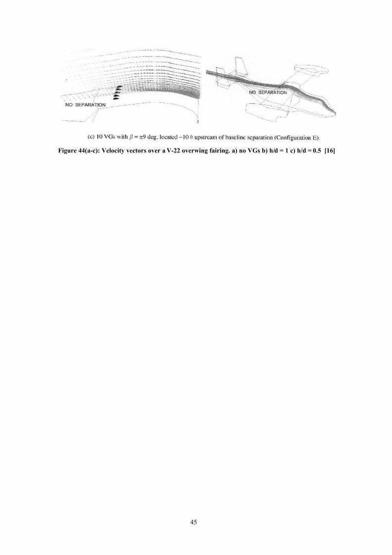
upstream as possible/ ;ut 7in M*,N also sho.s that placement to #ar upstream can increase#lo. separation and drag/ The +aval Sur#ace :ar#are entre per#ormed some 1"
calculations on the over.ing #airing o# a $(22 aircra#t simulating ten lo.(pro#ile $Gs/ 1igure
== a illustrate a cruise angel o# -° and light separation/ 'n #igure == b the placement too #ar upstream For too large $GsI o# the $Gs generate increased separation/ ;& moving the
generators *0 device heights do.nstream the baseline separation F#igure == cI is eliminated/
==
8/12/2019 Alternative Approaches to Rear End Drag Reduction
http://slidepdf.com/reader/full/alternative-approaches-to-rear-end-drag-reduction 45/49
(g2re ,,;a8c<3 !eloct9 =ectors o=er a !8%% o=erwng farng. a< no !*s b< 5Gd ? 1 c< 5Gd ? >./ 61$7
=,

8/12/2019 Alternative Approaches to Rear End Drag Reduction
http://slidepdf.com/reader/full/alternative-approaches-to-rear-end-drag-reduction 46/49
). Continued or*1urther investigations has been done in the areas o# boundar& la&er control but has not been
accounted #or in this report/ An alternative approach that could be used is the use o# sound
.aves to control the boundar& la&er separation as suggested b& A/ +ishi8a.a and S/ Takagi
M*?N/
>ne o# the most interesting areas .ould be the use o# air jets to #orm vorte< generators as
suggested b& / Abe et/ al/ M*QN/ The bene#it .ith that technolog& is that it .ould be possible
to control the strength o# the jets and thus control the strength o# the vortices created/ This
could translate into di##erent grade o# #lo. attachment at di##erent #lo. situations and most
bene#icial o# all is the possibilit& to shut them do.n and in that case the& do not in an& .a&contribute to the overall drag/ The do.nside o# them is the same as #or controlling boundar&
la&er .ith blo.ing and suctionV it reuires additional euipment #or generating the air#lo.s
and some kind o# control mechanism/ That adds cost and comple<it& to the construction and
that is never a good thing in terms o# maintenance and cost/
=6

8/12/2019 Alternative Approaches to Rear End Drag Reduction
http://slidepdf.com/reader/full/alternative-approaches-to-rear-end-drag-reduction 47/49
+. Conclusions9entionable is that there are measures that are more important to take than changing the
air#lo. around the rear o# a vehicle/ Those measures are the rounding o# #ront corners .hich
can contribute to as much as ,2O drag reduction M6N and a #ull(length underbod& seal can
contribute to as much as *,O drag reduction M6N/ These measures needs to be taken care o# be#ore it is interesting to take a look at rear end #lo./ ;ut .hen at least the #irst measure has
been taken care o# it can be bene#icial to take a look at altering rear end air#lo./
;ased on the results given in M*N and M*,N ' belie# that the most e##icient .a& to reduce base(
drag on blunt bodies Fsuch as busses and trucksI is the use o# $Gs in some .a&/ re#erabl&
lo.(pro#ile ones to reduce device drag or air(jet $Gs that can be turned on and o# duringdi##erent conditions/
>ne conclusion that can be made #rom the di##erent reports re#erred to in this .ork is that it is
di##icult to receive the same result in .ind(tunnel tests as those received in simulations/ This
is o# course e<plained b& the #act that there are realit&(#actors included in the resultsreceived #rom .ind(tunnel tests/ That is imper#ections in manu#acturing o# the model! leakage
and general losses that is not accounted #or in 1" modelling/
Some o# the results are gathered in table ?/
Technolog& T&pe o# improvement;oat(tailing 2 O reduction in d/
Aerod&namic boat(tail *0 O reduction in d/
;lo.n boundar& la&ers at GTR' ,0 O reduction in d/ C
1"! round rear edge *= O reduction in d/
1"! round rear edge! suction o# blCC 2= O reduction in d/:ind(tunnel test! boat(tail! blo.ing o# blCC *2 O reduction in d/
Transversal grooves on a shoulder 20 O shorter distance to reattachment
7ongitudinal grooves on a shoulder 66 O shorter distance to reattachment
Angled grooves on a shoulder +ot conclusive CCC
assive porous sur#ace Some improvement
9icro vorte< generators 00 counts
Table +3 #2mmar9 of some of t5e res2lts 4resented n t5e re4ort. H?com4ared to no aerod9namc
o4tmsaton at all ? s5ar4 front end no farng. HHbl?bo2ndar9 la9er. HHH? 61%7 s2ggest a /> I dragred2cton
5udging #rom these results it seems like blo.ing boundar& la&ers .ould be the most bene#icial
.a& to reduce rear end drag/ ;ut in this case! and several others! there is the realit& #actor to
consider as mentioned above in this section! tests per#ormed at GTR' .as per#ormed on anideal bod& and can not be easil& be compared to other results/
Then there is the traditional boat(tailing that come in second/ These results are more reliable
since the& are per#ormed on a real vehicle! still it is ideal in man& .a&s but the& give a hint o#
.hat kind o# results .e .ant to achieve/ And as ' mentioned earlier the& can be used as a
bench mark #or other tests since the& present the most ideal #lo. case Fa #ull boat(tailI but.ith some separation so that result can be some.hat improved/ Results much better than this
F#or e<ample the GTR' resultI should be seen upon .ith some scepticism be#ore presented to
others/ >r at least thoroughl& e<plained .h& that kind o# result is received/
=-

8/12/2019 Alternative Approaches to Rear End Drag Reduction
http://slidepdf.com/reader/full/alternative-approaches-to-rear-end-drag-reduction 48/49
So in real li#e! .hat seems to be the best technolog& to appl& to &our vehicles[ :ith little or
no di##erence in manu#acturing technolog& rounding o# the rear edges seems so #ar to be the
best .a& as #or no. to receive smaller contribution to the overall drag/ 'n combination .ith
grooves could improve the pressure recover& mechanism at the rear o# blunt vehicles and .ith
proper placement and design ' belie# that $Gs in some kind belong to #uture design o# high per#orming commercial vehicles/
=?

8/12/2019 Alternative Approaches to Rear End Drag Reduction
http://slidepdf.com/reader/full/alternative-approaches-to-rear-end-drag-reduction 49/49
,. eferencesM*N :ol#(einrich uchoV Aerod&namics o# Road $ehicles! 'S;+ 0(-6?0(002Q(-
M2N Al#ons GilhausV The main parameters determining the aerod&namic drag o# buses! +eue
Technologie! 9/A/+/ 9\nchen! 5une *Q?*
MN %d.in 5/ Salt8manV A summar& o# +ASA "r&denXs Truck Aerod&namic Research! SA%Technical aper Series! ?2*2?=
M=N Robert "/ ;levinsV Applied #luid d&namics handbook! 'S;+ 0(==2(2*2Q6(?
M,N Randall 7/ etersonV "rag reduction b& the addition o# a boat(tail to a bo< shaped vehicle!
+ASA ontractor Report *6**! August *Q?*
M6N Robert 5/ %nglarV "evelopment o# neumatic Aerod&namic "evices to 'mprove the
er#ormance! %conomics! and Sa#et& o# eav& $ehicles/ SA% aper 2000(0*(220?/ 5une *Q(2*! 2000
M-N Robert 5/ %nglarV Advanced Aerod&namic "evices to 'mprove the er#ormance!
%conomics! andling and Sa#et& o# eav& $ehicles/ SA% aper 200*(0*(20-2/ 9a& *=(*6!
200*
M?N ;/S/ 9asse&! 9echanics o# 1luids! si<th edition! 'S;+ 0(=*2(=(2?0(=MQN aola 1erraresiV ontrol o# ;oundar& 7a&er 1lo. on Trucks/ 9aster Thesis! Skri#t 200*(
*=/ "epartment o# Aeronautics! Ro&al 'nstitute o# Technolog&! S%(*00 == Stockholm! S.edenM*0N ;enjamin 7e Rou<V %<perimental Aerod&namics) Separation ontrol on Trailers o#
Trucks! A 9aster Thesis at Scania $ A;! RTT1 section/ 9a& 200
M**N :end& R/ 7anser! 5ames / Ross and Andre. %/ Kau#manV Aerod&namic er#ormance o#
a "rag Reduction "evice on a 1ull(Scale TractorETrailer! SA% aperQ*2*2,
M*2N G/$/ Selb&! 5// 7in and 1/G/ o.ard/ Turbulent #lo. separation control over a
back.ard(#acing ramp via transverse and s.ept grooves/ 5ournal o# 1luids %ngineering! 5une*QQ0! $ol/ **2
M*N 5/ / 7in and 1/ G/ o.ard! Turbulent 1lo. Separation ontrol Through assive
Techniues/ +ASA 7angle& Research Research enter! ampton! $AV and G/$/ Selb&! >ld"ominion Hniversit&! +or#olk! $A/ A'AA ?Q(0Q-6/ 9arch *(*6! *Q?Q
M*=N S/ Klausme&er! 9/ apadakis! 5/ 7inV A 1lo. hisics Stud& o# $orte< Generators on a
9ulti(%lement Air#oil! A'AA Q6(0,=?M*,N 5ohn / 7inV Revie. o# research on lo.(pro#ile vorte< generators to control boundar&(
la&er separation/ rogress in Aerospace Sciences ? F2002I ?Q(=20/
M*6N Kristian AngeleV %<perimental studies o# turbulent boundar& la&er separation and control/
Ro&al 'nstitute o# Technolog&! "epartment o# 9echanics/ Technical report 200)0?/ 'SS+
0=?(=6-@
M*-N :/ alarese! :// risler and G/7/ Gusta#sonV A#terbod& "rag Reduction b& $orte<
Generators! 1light "&namics 7aborator&! Air 1orce :right Aeronautical 7aboratories!
:right]atterson Air 1orce base! >hio/ A'AA(?,(0,=/ 5anuar& *=(*-! *Q?,E Reno! +evadaM*?N Akira +ishi8a.a! Shohei TakagiV To.ard smart control o# separation around a .ing Y
"evelopment o# an Active Separation ontrol S&stem! +ational Aerospace 7aborator& o#
5apan! ho#u! Tok&o! *?2(?,22
M*QN iro&uki Abe! Takehiko Sega.a! Taka&uki 9atsunuma! iro ^oshidaV 9anagement o# a
7ongitudinal $orte< #or Separation ontrol! +ational 'nstitute o# Advanced 'ndustrial Scienceand Technolog&! 5apan