Embed Size (px)
Citation preview

ALTERNATE APPROACHES TO VIBRATION AND SHOCK ANALYSIS USING NASTRAN
Richard E. Denver and Joseph M. MenichelloIBM Federal Systems Division
ABSTRACT
In analyzing sinusoidal steady-state vibration of structures, the NASTRAN(NASA Structural Analysis) program provides Rigid Formats 8 and 11 for directand modal frequency and random response solutions. The dynamic solution of thesinusoidal steady state vibration problem usually requires very large memorycore allocations and very long computational time. Our experience of analyzingthe Proteus system structures revealed an alternate solution set composed ofmodifying the eigenvector output of normal modes analysis, resulting in signifi-cant cost savings. This paper gives a step-by-step approach for the use ofthis alternate algorithm to the sinusoidal steady-state vibration problem.
The paper then deals with a method that derives an approximate equivalentstatic load to a base excitation shock analysis. The transient analysis in thecurrent level of NASTRAN, level 16, does not directly provide for either inputacceleration forcing functions or enforced boundary displacement. In thesuggested alternate analysis format, equivalent force input functions areapplied to the constrained locations by using the artifice of placing a largemass, with respect to the total system mass, at the desired acceleration inputpoints. This shortcut static analysis approach is presented to approximate theexpensive and time-consuming dynamics analysis approach to the base-excitationshock analysis.
Each of these methods has proved to be a reliable mechanical design guideand has correlated closely with empirical results.
INTRODUCTION
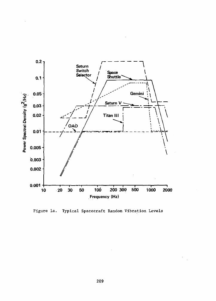
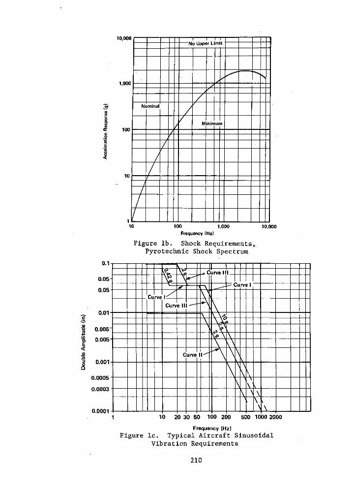
As the Environmental Design Analysis group at IBM's Federal Systems Divi-sion (FSD), Owego, NY, facility, our primary function is to guide the mechanicaldesign of FSD hardware during concept and development phases. Vibration andshock requirements associated with these products are often quite severe, asillustrated in figures la, Ib, Ic, and Id.
Structural analysis in support of the mechanical design of electronicsequipment is necessary to ensure compliance with the dynamic environmentalrequirements. Initially, the harmonic and random vibration excitation formats,as well as direct and modal transient shock capability of NASTRAN, have beenexercised to validate structural design. As the designs progress, many changesare incurred due to customer request, product improvement, compatibility with
199
https://ntrs.nasa.gov/search.jsp?R=19780004515 2018-06-27T16:13:54+00:00Z

fabrication techniques, and results of analysis, each requiring analyticalevaluation. In general, these changes must be assessed quickly and accuratelyand must result in minimum effect on cost and schedule. Because of long turn-around time and long computation time associated with the rigid formats we havebeen using, we began a study for an alternate, more efficient algorithm forthis solution phase.
The two methods resulting from this investigation for representing struc-tural deformations and stresses under the influence of vibration and shockenvironments are discussed under the headings "Vibration Stress Analysis" and"Shock Stress Analysis."
VIBRATION STRESS ANALYSIS
The following steps give the structural analyst a simplified shortcut indetermining maximum stresses in structural members during sinusoidal steady-state vibration at resonant frequency. This approach foregoes the direct ormodal frequency and random response analysis, Rigid Format 8 or 11, respec-tively, which requires very large memory core allocations and very long compu-tation time, and uses normal modes analysis, Rigid Format 3, and static analy-sis, Rigid Format 1, with an appropriate ALTER package given in the presenta-tion:
1) First, run a normal modes analysis (Rigid Format 3) to determinefundamental strutural resonances in three principal directions.
a) Specify MAX in the NORM field of the'EIGR continuation card.This normalizes maximum structural displacement for use inconjunction with the ALTER package given below.
b) Use CHKPNT YES in the Executive Control deck to checkpointall the necessary data and to recover the data in restart.This step will result in significant savings when used withthe ALTER package or to calculate additional vibratory modes.
2) To restart the checkpointed run to determine structural deformationand vibration stresses at resonance, the following items have to bespecified:
a) Specify a maximum structural displacement at the structuralresonance, (8). This can be estimated from the followingrelationship for a single-degree-of-freedom system.
ft 386.1 x G x 0b = 2 2
4TT X f
where
8 = single amplitude of response of structure (inches)
G = input steady state sinusoidal peak acceleration
Q = transmissibility at resonance
f = structural natural frequency
200

In the above relationship, it is assumed that G is a knownquantity, and £ has been determined^in the NASTRAN analysisusing Rigid Format 3. The transmissibility at resonance maybe determined from test data of a prototype or similar structure.If this data is not available, however, experience has shownthat a range of 0.05 < C/Cr < 0.10 is typical of three-dimen-sional frame structures of standard construction. Figure 2illustrates the interrelationship between structural dampingand amplification factor at resonance.
b) Insert the following ALTER package* in the. NASTRAN ExecutiveControl deck, which scales all output, and which includes struc-tural deformations and stresses. (F°r Level 16)
ALTER 108, 108SDR1 USET,,PHIA,,,GO,GM,,KFS,,/
PHIGG,QG/C,N,1/C,N,REIG $ADD PHIGG,/PHIG/C,Y,ALPHA=(1.0.0.0)7
C,Y,BETA = (0.0,0.0) $ADD QGG,/QG/C,Y,ALPHA=(1.0.0.0)7
C,Y,BETA=)0.0,0.0) $ENDALTER
c) In conjuction with the ALTER package, the user would also haveto specify the value of ALPHA on a PARAM card in the BULK DATAdeck. This value of ALPHA corresponds to the maximum structuralresponse, 8, calculated in the step 2a) of the procedure.
Example of this procedure follows:Input vibration level = 2 g peak sinusoidalNatural frequency of structure = 68 HzTransmissibility of structure = 10
g = 386.1 x G x q m 386.1 x 2 x 10 Q^2 ±nch
47T x f 4x(3.14) x(68)
Specifying in the BULK DATA deck
IPARAM [ALPHA 10.042 |0.0 | |\will result in linear scaling of all the output data blocks bya factor of 0.042. Obviously, because of the assumptions used,this method is restricted to linear analysis only.
Note: If the user were interested in a RESTART capability,DMAP statement 109 should also be altered to check-point data block PHIGG as well as PHIG and QG inthe Rigid Format 1.
*The authors wish to express their gratitude to the staff of the NASTRAN Sys-tems Management Office, NASA Langley Research Center, Hampton, Virginia,particularly to Mr. Joseph Walz for assistance offered in preparation of theALTER packages presented in this paper.
201

SHOCK STRESS ANALYSIS
The NASTRAN program provides two rigid formats for analyzing shock excita-tion problems. The transient analysis capability in the current level ofNASTRAN, level 16, however, does not directly provide for input acceleration-forcing functions or enforced boundary displacement. To overcome this defi-ciency in the program, modifications* had to be made to use the program forour specific application of base shock excitation of structures.
The following modifications were necessary to use Rigid Format 9 (DirectTransient):
1) Modify the math model as follows:
a) Place large seismic masses at all boundary points. These largeseismic masses at the support points are necessary to reducethe effects of feedback from the structural responses.
b) Use multipoint constraint (MFC) equations so that all boundarypoints will move together, allowing motion only in the directionof the shock.
c) Calculate a forcing function, f(t), which will produce thedesired acceleration function on the overall mass, structuralmass plus seismic mass, to satisfy the relationship F=ma atdifferent time intervals.
d) Input the forcing function, f(t), at the boundary points usingthe DAREA card in the BULK DATA deck.
2) Cold start Rigid Format 9.
The following modifications were necessary to use the Rigid Format 12(Transient Modal Analysis):
1) Run a normal modes analysis, Rigid Format 3, (we suggest usingthe Inverse Power method) to determine the fundamental structuralresonance in each principal direction along which shock pulse is tobe applied. Be sure to checkpoint this run. In this run, seismicmasses should not be attached to the boundary points in the mathmodel.
2) Modify the math model as follows:
a) Place large seismic masses at all boundary points; approximatelytimes the structural mass.
*The authors would like to thank Mr. Leon H. Arnold, IBM Owego, and Dr. HanChung Wang, IBM Endicott, for their technical assistance in developing thealternate solution methods and implementing them in the NASTRAN program.
202

b) Use MFC equations for all the boundary points to allow the .boundary points to move only in the direction of the shock.
c) Calculate a forcing function in the same manner as in usingRigid Format 9.
d) Input the forcing function at the boundary points; these arestructural attachment points either at the base or bulkhead ofaircraft, shipboard, submarine, or other test fixture frames.
3) Restart Rigid Format 12 using the structural resonance data obtainedin Rigid Format 3,
a) Bound the resonance of interest by using the PARAM LFREQ andPARAM HFREQ cards in the BULK DATA deck; the smaller the bandwidth,the more rapid the computation time. To minimize convergencetime, specify the same frequency range on the EIGR card asspecified on the preceding PARAM LFREQ and PARAM HFREQ cards.
NOTE: In all rigid formats, it is imperative to use a pre-processor program, such as BANDAID or BANDIT to reducethe semi-bandwidth of structural matrices.
The excessive time associated with model preparation and solution to shockanalyses using NASTRAN Rigid Formats 9 and 12 reduced their usefulness for thespecific application of mechanical design guidance in the earliest phases ofdesign.
The following method has been developed which approximates the effect ofthe shock pulse on the system through the use of a single-degree-of-freedomidealization, assuming that the fundamental mode parallel to the direction ofthe pulse is the sole contributor to maximum deformation and correspondingstresses. This method utilizes a combination of Rigid Formats 3 and 1 in placeof Rigid Format 9 or 12. Its implementation is described in the followinglists:
1) Perform a natural frequency analysis, Rigid Format 3, using the InversePower method to determine the fundamental structural resonance in eachplane in which a shock pulse is to be applied. The use of InversePower eigenvalue extraction will prove most efficient since only a fewof the resonant modes are of interest.
Note: One can force the program to search for resonant modes innumerically ascending order by specifying ND = small, NE =large (~100xND) in the EIGR card. This will reduce thecomputation time required to find the lowest natural fre-quency. It will significantly reduce the possibility ofterminating via termination codes 6 or 7 without determiningthe fundamental mode.
2) Calculate the dimensionless parameter t /T in whicho
ti = pulse period (seconds) of the shock to be applied
T = fundamental period of responding structure = 27T/ cu(seconds)
203

3) Using the plotted data in figure 3, extracted in part from reference4, determine x/A (acceleration amplitude magnification factor)
where
A = peak acceleration of input pulse (g)
x = maximum response acceleration of structure (g)
As shown in figure 3, the solution to the equation of motion and itsderivatives for the single-degree-of-freedom idealization are depend-ent on the degree of viscous damping exhibited by the responding sys-tem. This value may be determined from test data by examining thetransmissibility (Q) at resonance and correlating Q with the dampingfactor (C/Cr) through the use of graphs specified in reference 2,repeated in figure 2 for illustration. If test data is not available,experience has shown that a value of damping of 0.05<C/Cr < 0.10 istypical of most three-dimensional framed structures of standardconstruction.
4) Cold start in Rigid Format 1 specifying a loading, G, through the useof the NASTRAN GRAY card in which
G - AX!where
A = peak acceleration of input shock pulse, g
• • '
J£
-T- = dynamic load factor determined in step 3A.
CONCLUSIONS
The two methods discussed previously have proved to be a valuable engineer-ing aid during the developmental phase of mechanical designs. They have provedto be more cost- and time-effective than their counterparts in NASTRAN RigidFormats 9, 10, 11, and 12. Tables 1 and 2 summarize the time and cost compari-sons of the various solutions. In addition, the solutions have proved to yieldacceptable accuracy as evidenced in tables 3 and 4.
204

REFERENCES
1. Dr. Richard Eppink: A Comparison of Direct Integration vs Modal Methods ofAnalysis for Transient Response Analysis in NASTRAN. University of Virginia.
2. Application Selection Guide. Barry division of Barry Wright Corporation.
3. C.M. Harris and C.E. Crede: Shock and Vibration Handbook. New York:McGraw Hill, 1961, pp 23-1 through 23-37.
4. Robert R. Luke: The Impact Response of Single-Degree-of-Freedom Systemwith Viscous Damping. University of Texas, Structural Mechanics ResearchLaboratory, Austin, Texas.
5. NASTRAN User's Manual, NASA SP-222(03). Scientific and Technical Informa-tion Office, National Aeronautics and Space Administration, March, 1976.
6. NASTRAN Theoretical Manual, NASA SP-221-(03). Scientific and TechnicalInformation Office, National Aeronautics and Space Administration, March,1976.
7. NASTRAN Programmers Manual, NASA SP-223(03). Scientific and TechnicalInformation Office, National Aeronautics and Space Administration, March,1976.
8. Dr. Gordon C. Everstine: The BANDIT Computer Program for the Reduction ofMatrix Bandwidth for NASTRAN. Computation and Mathematics Department,Naval Ship Research and Development Center, Bethesda, MD 20034, March, 1972,Report No. 3827.
205

EXCP(I/O
operations)co
o a
PL, vH
CO0
H
1cd T3
to N
</>0 -H
rHcd4-1
</>
OEH•rlHi
«*•
•SolutionMethodop
COrH
CU
4-101
4-1 H
iT3
iH
CO
o HI a
J3 0)
4-1
S
^»
to -HO
0ft.
Unitanalyzed
0vO
00
O
vO
in
O
C
M vO
rH
CM
O
rH
in
O
VO
r»
oo rH
o
oo
r~
o v
o «
00
C
Ti
t^
.0
0
00
in
C
M
-*CM
rH
in
CM
C
M
CO
o oo
oo -a-
CM
<r I-HO
O
CM
O
OO
O
CM
l>»
CM
C
O**
CO
C
Tv "d"
vO
o |o 1
m
IcolrH
|rH
| O
[o
j
O
lev) 1O
C
O
VO
COin
coC
O
1
o
|vo|
mw
r-
- t~
-.
. .
m
r-» m
&\ in
voH
JC
MJ
CM
CM
OO
O
CM
O
O
-d- i-H
<
•co
vo oco
<f
<fr
r*^ o
r~- oo
vo
r-
- oo
mc
Mc
oV
O
00
VO
VO
C
M
OO
-v
tC
MrH
rH
U
1 rH
C
M
/--*
CO
01 01
CO CO
CO
rH
O
rH
C
J C
O
rHrH
,0
rH
&3
3CO
CO
rH
CO
crco co
s-i ai
4-tm
co
cd•^ a a
HI -rjrH
O
O
to
Ocfl
rO
pi Q
J _*^•O
H
i C
O
4J 4J
q cd
co rH
o»g
to
to
< a
ooCMCMm00
<r* to
CO 0)
3 N
cu >>
4-1 rH
4-10
C
d
iHto
C Hi
PI < n>
••-N
CO
/—
N
Q) CO
COCO
CO CO
cd cd
cdU
rH
O
C
O
rH
O
33
"
3CO
CO CO
H
CO
rH
^
s— '
*^s .
0)4-1HI
*Oto
00)
,C4-1
J-J
CM
OinmvOH
COCO
O
*
< -H
*
H H
iCO
O
O3
<
JJ r
lCO
H
4J4J ^
- O
^
O 2
0) U
to H
rH
cd
p* C
O W
(4
Notes:*A11 solutions performed on IBM System/360 Model 85; NASTRAN level 15.0.1, with BANDIT preprocessing
**NASTRAN Level 15.5.2, IBM System/370-158.
DOF - degree of freedomRF - rigid formatCPU - central processing unitEXCP - Execute Channel program
20
6

CN
wrJ
'HO2;
CUN•HCOCUOO("> ,
O3&oX)CUN•HrHrHcd4-1
OH
COCU4Jph,
XI
(xiv-
/
COeo-HcdCUp.00Mx-vCOCUe4-1
«></>
4J
ad0•H4-13rHOC/3
-004-1CU6
1
4-1•Hc
CU4-1•Ha•HP
uiHjj
OT301N^rHcdccd
CO4-1eCUGCUrHCUCOciH0a
o00oo*
VO
ooOO
CMrHo0O•
1 —VOC
XI
OOr!
vOCM
CT>
CO0>4-1
COa
Cd
CU 0
4-1 -H
,0
0
CO
3cu
a ca
•H
M C
O
00
CM
CMinoom
Mca
cu3
N
4J >>
4J0
Cd
-Hn
G
CP
M <
£>
oCO
vO
OiH
O
OO
O*>
*00
rHC
M
CTi
O rH
oo m-*
CMrH
0rHOo*
p.
>-
VO
O 0
o o
r>! cbvo oorH
<3-
CO
C
Mi-H
/— s
cacu4-1
COC
cd
cu o
•H ,0
rH
CO
3cd
C co
13 cd
O
)-l CO
vOrHooM
ooCM
000
«-
^J-C
O
0o0r^v£)rHC
Ocu4-1cd(-1a)4-1rH
ooCO
0oin•*
vOrH00
oo•
rHCM
CM
ooinrHao4-1 O
3 X
!rH
4->
o
cuco
e•
om•^o00•S
CO0rHrHorHorHo0
•
rHCO
m0orHCO
m~
cacu•P
C
OC
cd
cu o
4J -H
XI
O
CO
3u
a coiM
cd•H
V
4 C
O
CM
£0mr.
invOrHgC/3ca3 co
cu <:4J H
0 0
M <
(it H
om1 —CM
VO
VOr.
CM
CO
-3-
CM
vO^>ino00•
ooooCM
0oCM
>3°C
N
COCU
4-1cdaMcu4-1
<
omCO
o0vO*
vOrH00
o0vO*3"
rHo•H 13
4-1 O
3 X
!•H
4J
O
01co
e
COcuCOcdu•§caco
207

TABLE 3. - RESULTS COMPARISON OF ALTERNATE SOLUTION METHODSFOR OBTAINING MAXIMUM VIBRATION DISPLACEMENTS AND STRESSES
Unitanalyzed
ProteusAnalyzerUnit
Solutionmethod
Modalfrequency &randomresponse
Alternatesolutionmethod
Engineeringdevelopmenttest
Direction
XYZ
XYZ
XYZ
Fundamentalnaturalfrequency(Hz)
66188406
66188406
72*190*420*
Maximum peakaxial stress
2(Ibf/in )
10,400**NANA
13,710--
NANANA
Notes:*Variation in test/analytical results attributed to weight discrepancy ( 50 Ib)and modified structural configuration „
**Based on 20% damping; 5% damping yielded 40,100 Ibf/in maximum stress
TABLE 4. - RESULTS COMPARISON OF ALTERNATE SOLUTION METHODSFOR OBTAINING MAXIMUM SHOCK DISPLACEMENTS AND STRESSES
Unitanalyzed
ProteusSTM/TACTASElectronicsRack
Eigenvalue extraction
Direction
-
XY
Z
XY
Z
Naturalfrequency(Hz)
-
12470, 125,146Not found
12270, 124,146Not found
Loadingcondition
Navyhigh impactMedium Weight,inclined ,hammer-dropshocktest
Shock stress analysis
Solutionmethod
Directtransientanalysis
Alternatesolutionmethod
Engineeringdevelopmenttesting
Maximum peakaxial stress(Ibf/in2)
31,770
28,905
29,000
208
0.2
0.1
0.05
£? 0.03
g 0.02
I °-01CO
0.005 -
0.003
0.002
0.001
Saturn /
f"»*J / SpaceS6'60^ I Shuttle'
SpaceCU..M-I
•~\\
•V\
10 20 30 50 100 200300 500 1000 2000
Frequency (Hz)
Figure la. Typical Spacecraft Random Vibration Levels
209
Ii.
8
oc
I
0,000
1,000
100
Ni
/
1
/
>minal
/
//
/
/ ^
N
/
/
o Upper Limit
y
./
M
X1
^
nirr
,/•
ur
X*
n
^
• s
10 100 1,000 10,0Frequency (Hz)
Figure Ib. Shock Requirements,Pyrotechnic Shock Spectrum
u. i •
0.05-
U.UO
0.005-
0.005
n nni-
0.0005
0.0003
n nnm -
Ci rve
\ff
yv_
|XX
Curv
Ny
el l
C
L^
—
urve
|l,-^c
<-\
\ ^\
-A\\
„-
jrve II
_^-
\\\O
i-^ <
\\?
$V \\\
\\ \\\
;u
\
\
\
rv
\\
\\
\\
j I
\\\\
\
A\
\I 10 20 30 50 100 200 500 1000 2000
Frequency (Hz)
Figure Ic. Typical Aircraft SinusoidalVibration Requirements
210

360-
270-
3 90-co« o-o>
-90-
-180-
-270-
-3600 0.00610.01210.018 0.024I0.0300.03610.04210.048 Time (Sec)
Figure Id. Typical Navy Medium-Weight-Hammer-'Drop Anvil Response
0.010.1 0.2 0.4 0.6 1
Ratio (fd/fn)4 6 10
Figure 2. Family of Transmissibility Curvesfor a Single-Degree-of-Freedom System
211

:x
1re
_
i
0.4 0.8 1.2 1.6 2.0 2.4 2.8 3.2 3.6
0.4
i• reu.
_o
re
0 0.4 0.8 1.2 1.6 2.0 2.4 2.8 3.2 16
Time Ratio (t-j/T)
Figure 3. Shock Transmissibility Curves for aSingle-Degree-of-Freedom System with Directly Coupled
Viscous Damping Subjected to Sinusoidal andTerminal-Peak Sawtooth Shock Pulses
212