Embed Size (px)
Citation preview
Efficient
Flexible
Reliable
alpha Value Line - NPS Sizing and Technical Data
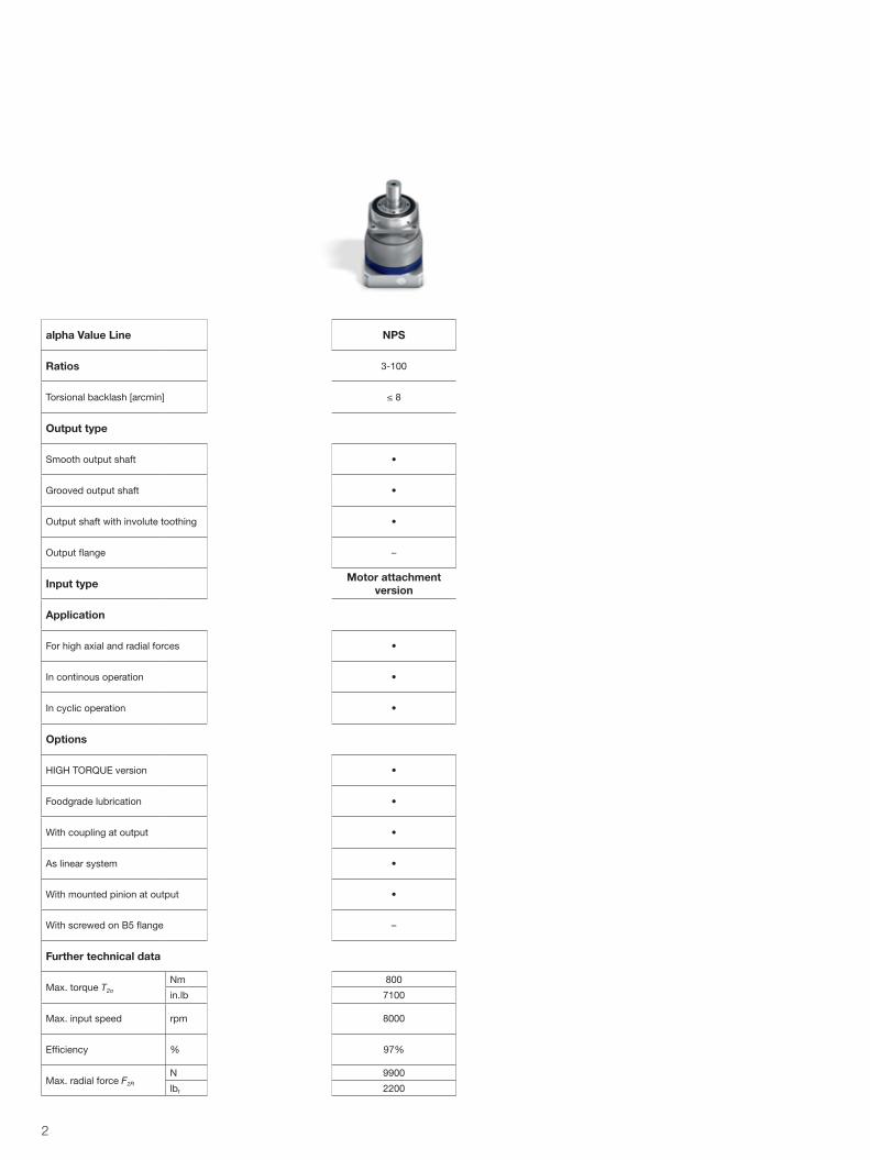
alpha Value Line NP NPS NPL NPT NPR
Ratios 3-100
Torsional backlash [arcmin] ≤ 8
Output type
Smooth output shaft • • • – •
Grooved output shaft • • • – •
Output shaft with involute toothing – • • – •
Output flange – – – • –
Input type Motor attachment version
Application
For high axial and radial forces – • • – •
In continous operation • • • • –
In cyclic operation • • • • •
Options
HIGH TORQUE version • • • • •
Foodgrade lubrication • • • • •
With coupling at output • • • • •
As linear system • • • – •
With mounted pinion at output • • • – •
With screwed on B5 flange • – – – –
Further technical data
Max. torque T2α
Nm 800 800 800 800 800
in.lb 7100 7100 7100 7100 7100
Max. input speed rpm 10000 8000 8000 10000 8000
Efficiency % 97% 97% 97% 97% 97%
Max. radial force F2R
N 8000 9900 9900 4800 9900
lbf 1800 2200 2200 1080 2200
2
Contents
Sizing of the alpha Value Line – NPS 4
NPS 015S 6
NPS 025S 8
NPS 035S 10
NPS 045S 12
Glossary 14
Order codes 15
WITTENSTEIN alpha adapted for any axis
The perfect drive solution whatever the requirements are
WITTENSTEIN alpha develops complete, single- supplier solutions for driving any axis. They can be used in virtually any application – from high-precision axes in machine tools and manufacturing systems to packaging machinery where maximum productivity is a must. The name WITTENSTEIN alpha is synonymous with premium quality and optimal reliability, high pre- cision and synchronization accuracy, maximum power density, a long lifetime and very simple motor mounting.The alpha Value Line is a new product family that unites these characteristics – which are specially adapted for applications in the value segment or high-end secondary axes – in a class-appropriate way.
Benefits of the alpha Value Line:
· Rapid availability regardless of the batch size · Optimal flexibility · Ability to react promptly to changing customer requirements
· Assembly to order
3
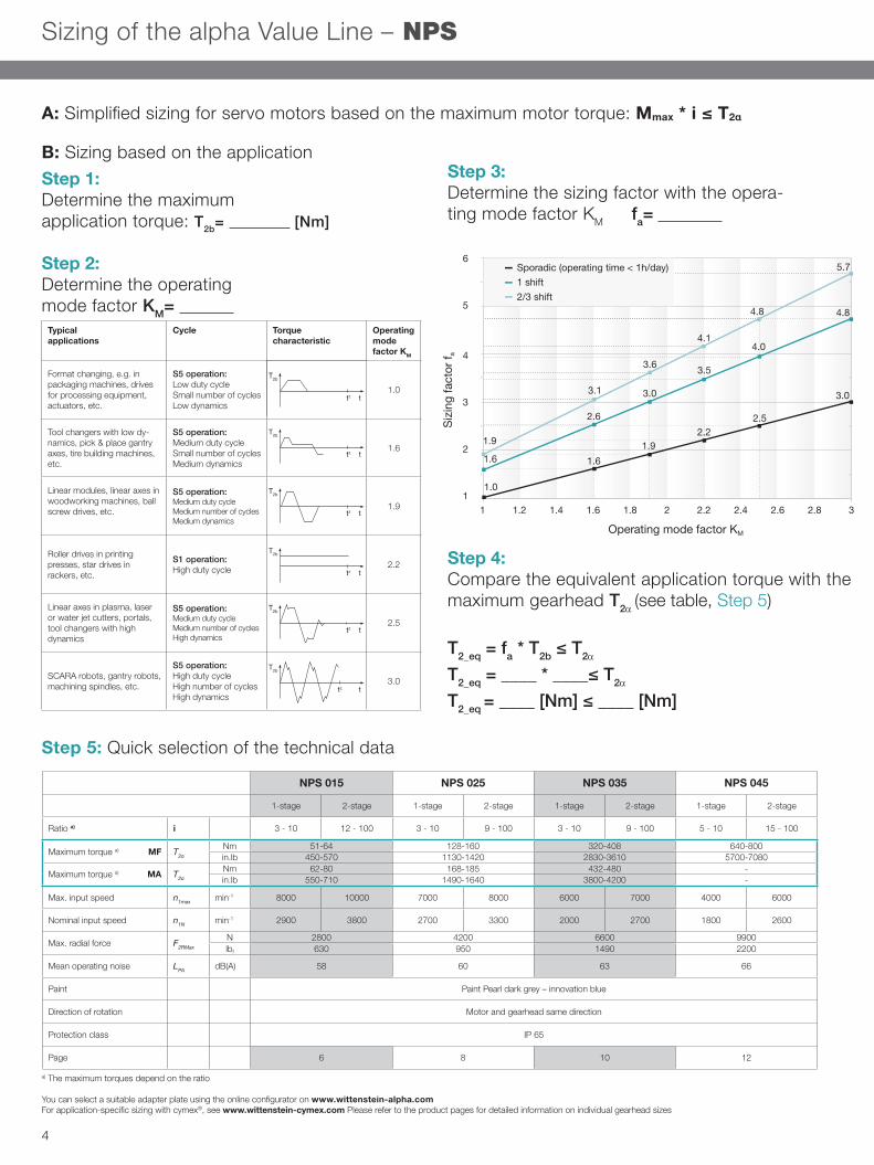
Sizing of the alpha Value Line – NPS
A: Simplified sizing for servo motors based on the maximum motor torque: Mmax * i ≤ T2α
Step 1: Determine the maximum application torque: T2b= [Nm]
Step 2: Determine the operating mode factor KM=
Step 3: Determine the sizing factor with the opera-ting mode factor KM fa=
Step 4: Compare the equivalent application torque with the maximum gearhead T2α (see table, Step 5)
T2_eq = fa * T2b ≤ T2α
T2_eq = ____ * ____≤ T2α
T2_eq = ____ [Nm] ≤ ____ [Nm]
Step 5: Quick selection of the technical data
B: Sizing based on the application
Operating mode factor KM
Siz
ing
fact
or f a
Sporadic (operating time < 1h/day)1 shift2/3 shift
6
5
4
3
2
11 1.2 1.4 1.6 1.8 2 2.2 2.4 2.6 2.8 3
1.6
1.9
1.61.9
3.0
3.6
4.1
3.5
2.22.5
4.0
4.8 4.8
5.7
3.0
2.6
3.1
1.0
2
Auslegung alpha Value Line – NP
A: Vereinfachte Auslegung bei Servomotoren über maximales Motormoment: Mmax * i ≤ T2α
Schritt 1: Bestimmung des maximalen Applikationsmoments T2b: [Nm]
Schritt 2: Bestimmung des Betriebsartfaktors KM:
Anwendungs- beispiel
Zyklus Charakterististischer Drehmomenten-verlauf
Betriebs- artfaktor KM
Formatverstellung z.B. bei Verpackungsmaschinen, Antriebe für Bearbeitungsvor-richtungen, Stellantriebe, etc.
S5 Betrieb: Geringe Einschaltdauer Geringe Zyklenzahl Geringe Dynamik
1,0
Werkzeugwechsler mit gerin-ger Dynamik, Bestückungs-portalachsen, Reifenaufbau-maschine etc.
S5 Betrieb: Mittlere Einschaltdauer geringe Zyklenzahl mittlere Dynamik
1,6
Linearmodule, Linearachsen in Holzbearbeitungsmaschi-nen, Antrieb von Kugelgewin-detrieben etc.
S5 Betrieb: Mittlere ED Mittlere Zyklenzahl Mittlere Dynamik
1,9
Walzenantrieb in Druck-maschinen, Sternantrieb Abfüllmaschine etc.
S1 Betrieb: Hohe Einschaltdauer
2,2
Linearachsen in Plasma-, Laser-, Wasserstrahlschnei-der, Portale, Werkzeug-wechsler mit hoher Dynamik
S5 Betrieb: Mittlere Einschaltdauer Mittlere Zyklenzahl Hohe Dynamik;
2,5
Scara RoboterPortalroboterBearbeitungsspindeln etc.
S5 Betrieb: Hohe Einschaltdauer Hohe Zyklenzahl Hohe Dynamik
3,0
Schritt 3: Bestimmung des Auslegungsfaktors mit dem Betriebsartfaktor KM fa:
Schritt 4: Abgleich äquivalentes Applikationsmoment und max. Getriebedrehmoment T2α (aus Tabelle Schritt 5)
T2_eq = fa * T2b ≤ T2α
T2_eq = ____ * ____≤ T2α
T2_eq = ____ [Nm] ≤ ____ [Nm]
NP 005 NP 015 NP 025 NP 035 NP 045
1-stufig 2-stufig 1-stufig 2-stufig 1-stufig 2-stufig 1-stufig 2-stufig 1-stufig 2-stufig
Übersetzung i 3 - 100
Max. Drehmoment a) MF T2α Nm 18-23 51-64 128-160 320-408 640-800
Max. Drehmoment a) MA T2α Nm - 62-88 160-200 432-488 -
Max. Drehzahl n1max min-1 10000 10000 8000 10000 7000 8000 6000 7000 4000 6000
Zul. Mittlere Drehzahl n1N min-1 3800 4000 3300 3800 3100 3300 2700 3100 2000 2600
Max. Radialkraft F2RMax N 800 1700 2800 5000 8000
Mittleres Laufgeräusch LPA dB(A) 58 58 60 63 66
Lackierung Perldunkelgrau - Innovation blue
Drehrichtung An- und Abtriebsseite gleichsinnig
Schutzart IP 64
Seite xx xx xx xx xx
Schritt 5: Technische Daten Schnellauswahl
a) Maximale Drehmomente sind übersetzungsabhängig
Die passende Adapterplatte kann mit dem Onlinekonfigurator unter www.wittenstein-alpha.de ausgewählt werden. Applikationsspezifische Auslegung mit cymex® – www.cymex.de. Detaillierte Hinweise zu den einzelnen Getriebebaugrößen finden sich auf den jeweiligen Produktseiten
T2b
T2b
T2b
T2b
T2b
T2b
t
t
t
t
t
t
tz
tz
tz
tz
tz
tz
T2b
T2b
T2b
T2b
T2b
T2b
t
t
t
t
t
t
tz
tz
tz
tz
tz
tz
T2b
T2b
T2b
T2b
T2b
T2b
t
t
t
t
t
t
tz
tz
tz
tz
tz
tz
T2b
T2b
T2b
T2b
T2b
T2b
t
t
t
t
t
t
tz
tz
tz
tz
tz
tz
T2b
T2b
T2b
T2b
T2b
T2b
t
t
t
t
t
t
tz
tz
tz
tz
tz
tz
T2b
T2b
T2b
T2b
T2b
T2b
t
t
t
t
t
t
tz
tz
tz
tz
tz
tz
1
1,5
2
2,5
3
3,5
4
4,5
5
5,5
6
1 1,2 1,4 1,6 1,8 2 2,2 2,4 2,6 2,8 3
Ausl
egun
gsfa
ktor
f a [-
]
Betriebsartfaktor KM
Auslegungsfaktor fa
sporatisch (Betriebszeit < 1h/Tag) 1-Schicht 2-Schicht
1,0
1,6
1,611
1,5
2
2,5
3
3,5
4
4,5
5
5,5
6
1,2 1,4 1,8 2 2,2 2,4 2,6 2,8 3
1,92,2
2,5
1,6
2,6
3,0
3,5
4,0
1,9
3,1
3,6
4,1
4,8
6,2
5,2
3,2
Betriebsartfaktor KM
Au
sleg
un
gsf
akto
r f
a
B: Auslegung über die Applikation
NPS 015 NPS 025 NPS 035 NPS 045
1-stage 2-stage 1-stage 2-stage 1-stage 2-stage 1-stage 2-stage
Ratio a) i 3 - 10 12 - 100 3 - 10 9 - 100 3 - 10 9 - 100 5 - 10 15 - 100
Maximum torque a) MF T2α
Nm 51-64 128-160 320-408 640-800in.lb 450-570 1130-1420 2830-3610 5700-7080
Maximum torque a) MA T2α
Nm 62-80 168-185 432-480 -in.lb 550-710 1490-1640 3800-4200 -
Max. input speed n1max min-1 8000 10000 7000 8000 6000 7000 4000 6000
Nominal input speed n1N min-1 2900 3800 2700 3300 2000 2700 1800 2600
Max. radial force F2RMax
N 2800 4200 6600 9900lbf 630 950 1490 2200
Mean operating noise LPA dB(A) 58 60 63 66
Paint Paint Pearl dark grey – innovation blue
Direction of rotation Motor and gearhead same direction
Protection class IP 65
Page 6 8 10 12
2
Auslegung alpha Value Line – NP
A: Vereinfachte Auslegung bei Servomotoren über maximales Motormoment: Mmax * i ≤ T2α
Schritt 1: Bestimmung des maximalen Applikationsmoments T2b: [Nm]
Schritt 2: Bestimmung des Betriebsartfaktors KM:
Anwendungs- beispiel
Zyklus Charakterististischer Drehmomenten-verlauf
Betriebs- artfaktor KM
Formatverstellung z.B. bei Verpackungsmaschinen, Antriebe für Bearbeitungsvor-richtungen, Stellantriebe, etc.
S5 Betrieb: Geringe Einschaltdauer Geringe Zyklenzahl Geringe Dynamik
1,0
Werkzeugwechsler mit gerin-ger Dynamik, Bestückungs-portalachsen, Reifenaufbau-maschine etc.
S5 Betrieb: Mittlere Einschaltdauer geringe Zyklenzahl mittlere Dynamik
1,6
Linearmodule, Linearachsen in Holzbearbeitungsmaschi-nen, Antrieb von Kugelgewin-detrieben etc.
S5 Betrieb: Mittlere ED Mittlere Zyklenzahl Mittlere Dynamik
1,9
Walzenantrieb in Druck-maschinen, Sternantrieb Abfüllmaschine etc.
S1 Betrieb: Hohe Einschaltdauer
2,2
Linearachsen in Plasma-, Laser-, Wasserstrahlschnei-der, Portale, Werkzeug-wechsler mit hoher Dynamik
S5 Betrieb: Mittlere Einschaltdauer Mittlere Zyklenzahl Hohe Dynamik;
2,5
Scara RoboterPortalroboterBearbeitungsspindeln etc.
S5 Betrieb: Hohe Einschaltdauer Hohe Zyklenzahl Hohe Dynamik
3,0
Schritt 3: Bestimmung des Auslegungsfaktors mit dem Betriebsartfaktor KM fa:
Schritt 4: Abgleich äquivalentes Applikationsmoment und max. Getriebedrehmoment T2α (aus Tabelle Schritt 5)
T2_eq = fa * T2b ≤ T2α
T2_eq = ____ * ____≤ T2α
T2_eq = ____ [Nm] ≤ ____ [Nm]
NP 005 NP 015 NP 025 NP 035 NP 045
1-stufig 2-stufig 1-stufig 2-stufig 1-stufig 2-stufig 1-stufig 2-stufig 1-stufig 2-stufig
Übersetzung i 3 - 100
Max. Drehmoment a) MF T2α Nm 18-23 51-64 128-160 320-408 640-800
Max. Drehmoment a) MA T2α Nm - 62-88 160-200 432-488 -
Max. Drehzahl n1max min-1 10000 10000 8000 10000 7000 8000 6000 7000 4000 6000
Zul. Mittlere Drehzahl n1N min-1 3800 4000 3300 3800 3100 3300 2700 3100 2000 2600
Max. Radialkraft F2RMax N 800 1700 2800 5000 8000
Mittleres Laufgeräusch LPA dB(A) 58 58 60 63 66
Lackierung Perldunkelgrau - Innovation blue
Drehrichtung An- und Abtriebsseite gleichsinnig
Schutzart IP 64
Seite xx xx xx xx xx
Schritt 5: Technische Daten Schnellauswahl
a) Maximale Drehmomente sind übersetzungsabhängig
Die passende Adapterplatte kann mit dem Onlinekonfigurator unter www.wittenstein-alpha.de ausgewählt werden. Applikationsspezifische Auslegung mit cymex® – www.cymex.de. Detaillierte Hinweise zu den einzelnen Getriebebaugrößen finden sich auf den jeweiligen Produktseiten
T2b
T2b
T2b
T2b
T2b
T2b
t
t
t
t
t
t
tz
tz
tz
tz
tz
tz
T2b
T2b
T2b
T2b
T2b
T2b
t
t
t
t
t
t
tz
tz
tz
tz
tz
tz
T2b
T2b
T2b
T2b
T2b
T2b
t
t
t
t
t
t
tz
tz
tz
tz
tz
tz
T2b
T2b
T2b
T2b
T2b
T2b
t
t
t
t
t
t
tz
tz
tz
tz
tz
tz
T2b
T2b
T2b
T2b
T2b
T2b
t
t
t
t
t
t
tz
tz
tz
tz
tz
tz
T2b
T2b
T2b
T2b
T2b
T2b
t
t
t
t
t
t
tz
tz
tz
tz
tz
tz
1
1,5
2
2,5
3
3,5
4
4,5
5
5,5
6
1 1,2 1,4 1,6 1,8 2 2,2 2,4 2,6 2,8 3
Ausl
egun
gsfa
ktor
f a [-
]
Betriebsartfaktor KM
Auslegungsfaktor fa
sporatisch (Betriebszeit < 1h/Tag) 1-Schicht 2-Schicht
1,0
1,6
1,611
1,5
2
2,5
3
3,5
4
4,5
5
5,5
6
1,2 1,4 1,8 2 2,2 2,4 2,6 2,8 3
1,92,2
2,5
1,6
2,6
3,0
3,5
4,0
1,9
3,1
3,6
4,1
4,8
6,2
5,2
3,2
Betriebsartfaktor KM
Au
sleg
un
gsf
akto
r f
a
B: Auslegung über die Applikation
2
Auslegung alpha Value Line – NP
A: Vereinfachte Auslegung bei Servomotoren über maximales Motormoment: Mmax * i ≤ T2α
Schritt 1: Bestimmung des maximalen Applikationsmoments T2b: [Nm]
Schritt 2: Bestimmung des Betriebsartfaktors KM:
Anwendungs- beispiel
Zyklus Charakterististischer Drehmomenten-verlauf
Betriebs- artfaktor KM
Formatverstellung z.B. bei Verpackungsmaschinen, Antriebe für Bearbeitungsvor-richtungen, Stellantriebe, etc.
S5 Betrieb: Geringe Einschaltdauer Geringe Zyklenzahl Geringe Dynamik
1,0
Werkzeugwechsler mit gerin-ger Dynamik, Bestückungs-portalachsen, Reifenaufbau-maschine etc.
S5 Betrieb: Mittlere Einschaltdauer geringe Zyklenzahl mittlere Dynamik
1,6
Linearmodule, Linearachsen in Holzbearbeitungsmaschi-nen, Antrieb von Kugelgewin-detrieben etc.
S5 Betrieb: Mittlere ED Mittlere Zyklenzahl Mittlere Dynamik
1,9
Walzenantrieb in Druck-maschinen, Sternantrieb Abfüllmaschine etc.
S1 Betrieb: Hohe Einschaltdauer
2,2
Linearachsen in Plasma-, Laser-, Wasserstrahlschnei-der, Portale, Werkzeug-wechsler mit hoher Dynamik
S5 Betrieb: Mittlere Einschaltdauer Mittlere Zyklenzahl Hohe Dynamik;
2,5
Scara RoboterPortalroboterBearbeitungsspindeln etc.
S5 Betrieb: Hohe Einschaltdauer Hohe Zyklenzahl Hohe Dynamik
3,0
Schritt 3: Bestimmung des Auslegungsfaktors mit dem Betriebsartfaktor KM fa:
Schritt 4: Abgleich äquivalentes Applikationsmoment und max. Getriebedrehmoment T2α (aus Tabelle Schritt 5)
T2_eq = fa * T2b ≤ T2α
T2_eq = ____ * ____≤ T2α
T2_eq = ____ [Nm] ≤ ____ [Nm]
NP 005 NP 015 NP 025 NP 035 NP 045
1-stufig 2-stufig 1-stufig 2-stufig 1-stufig 2-stufig 1-stufig 2-stufig 1-stufig 2-stufig
Übersetzung i 3 - 100
Max. Drehmoment a) MF T2α Nm 18-23 51-64 128-160 320-408 640-800
Max. Drehmoment a) MA T2α Nm - 62-88 160-200 432-488 -
Max. Drehzahl n1max min-1 10000 10000 8000 10000 7000 8000 6000 7000 4000 6000
Zul. Mittlere Drehzahl n1N min-1 3800 4000 3300 3800 3100 3300 2700 3100 2000 2600
Max. Radialkraft F2RMax N 800 1700 2800 5000 8000
Mittleres Laufgeräusch LPA dB(A) 58 58 60 63 66
Lackierung Perldunkelgrau - Innovation blue
Drehrichtung An- und Abtriebsseite gleichsinnig
Schutzart IP 64
Seite xx xx xx xx xx
Schritt 5: Technische Daten Schnellauswahl
a) Maximale Drehmomente sind übersetzungsabhängig
Die passende Adapterplatte kann mit dem Onlinekonfigurator unter www.wittenstein-alpha.de ausgewählt werden. Applikationsspezifische Auslegung mit cymex® – www.cymex.de. Detaillierte Hinweise zu den einzelnen Getriebebaugrößen finden sich auf den jeweiligen Produktseiten
T2b
T2b
T2b
T2b
T2b
T2b
t
t
t
t
t
t
tz
tz
tz
tz
tz
tz
T2b
T2b
T2b
T2b
T2b
T2b
t
t
t
t
t
t
tz
tz
tz
tz
tz
tz
T2b
T2b
T2b
T2b
T2b
T2b
t
t
t
t
t
t
tz
tz
tz
tz
tz
tz
T2b
T2b
T2b
T2b
T2b
T2b
t
t
t
t
t
t
tz
tz
tz
tz
tz
tz
T2b
T2b
T2b
T2b
T2b
T2b
t
t
t
t
t
t
tz
tz
tz
tz
tz
tz
T2b
T2b
T2b
T2b
T2b
T2b
t
t
t
t
t
t
tz
tz
tz
tz
tz
tz
1
1,5
2
2,5
3
3,5
4
4,5
5
5,5
6
1 1,2 1,4 1,6 1,8 2 2,2 2,4 2,6 2,8 3
Ausl
egun
gsfa
ktor
f a [-
]
Betriebsartfaktor KM
Auslegungsfaktor fa
sporatisch (Betriebszeit < 1h/Tag) 1-Schicht 2-Schicht
1,0
1,6
1,611
1,5
2
2,5
3
3,5
4
4,5
5
5,5
6
1,2 1,4 1,8 2 2,2 2,4 2,6 2,8 3
1,92,2
2,5
1,6
2,6
3,0
3,5
4,0
1,9
3,1
3,6
4,1
4,8
6,2
5,2
3,2
Betriebsartfaktor KM
Au
sleg
un
gsf
akto
r f
a
B: Auslegung über die Applikation
Typical applications
Cycle Torque characteristic
Operating mode factor KM
Format changing, e.g. in packaging machines, drives for processing equipment, actuators, etc.
S5 operation:Low duty cycleSmall number of cyclesLow dynamics
1.0
Tool changers with low dy-namics, pick & place gantry axes, tire building machines, etc.
S5 operation: Medium duty cycle Small number of cycles Medium dynamics
1.6
Linear modules, linear axes in woodworking machines, ball screw drives, etc.
S5 operation: Medium duty cycle Medium number of cycles Medium dynamics
1.9
Roller drives in printing presses, star drives in rackers, etc.
S1 operation:High duty cycle 2.2
Linear axes in plasma, laser or water jet cutters, portals, tool changers with high dynamics
S5 operation: Medium duty cycle Medium number of cycles High dynamics
2.5
SCARA robots, gantry robots, machining spindles, etc.
S5 operation: High duty cycle High number of cycles High dynamics
3.0
a) The maximum torques depend on the ratio
You can select a suitable adapter plate using the online configurator on www.wittenstein-alpha.comFor application-specific sizing with cymex®, see www.wittenstein-cymex.com Please refer to the product pages for detailed information on individual gearhead sizes
4
alpha
3
100
1000
10000
1 10 100
Äqui
vale
nte
Abtr
iebs
kraf
t F2_
eq[N
]
Abstand vom Wellenbund / Flansch x2 [mm]
Kraft am Abtrieb - NP
NP 005
NP 015
NP 025
NP 035
NP 045
Berücksichtigung von Radial- oder Axialkräften am Abtrieb:Bei Kräften auf den Abtrieb bitte zusätzlich Schritt 6 und 7 durchführen (z.B. durch montierte Riemenscheiben, Ritzel oder Hebel).
Bedingungen bei wirkender Axialkraft F2a:
1. F2a ≤ 0,25 * F2r ⇒ ( _____ ≤ 0,25 * _____) ist erfüllt ist nicht erfüllt: Auslegung mit cymex
2. y2 ≤ x2 ⇒ ( _____ ≤ _____) ist erfüllt ist nicht erfüllt: Auslegung mit cymex
Schritt 7: Bestimmung der max. äquivalenten Kraft auf den Abtrieb F2_eq
F2_eq = F2r + 0,25 * F2a ≤ F2RMax (Bestimmung F2RMax aus Diagramm unten)
F2_eq = _____ + 0,25 * _____ ≤ _____
F2_eq = _____ [N] ≤ _____ [N] ist erfüllt
ist nicht erfüllt: Höhere Radialkräfte mit den Varianten NPS, NPL und NPR sind möglich.
Schritt 6 (falls externe Kräfte vorhanden): Bestimmung der wirkenden Kräfte und Überprüfung der Randbedingungen
Radialkraft F2r: ______ [N]Abstand Radialkraft x2: ______ [mm]Axialkraft F2a: ______ [N]Abstand Axialkraft y2: ______ [mm] (erforderlich wenn F2a anliegt)
sporadisch / 1-Schicht2-/3-Schicht
500
1000
5000
10000
5 10 100
100
1 50
Abstand Radialkraft x2 [mm]
Max
imal
e R
adia
lkra
ft F
2RM
ax [N
]
F2r
F2a
X2
Y2y 2
x2
alpha
1 5 10 50 1001000
10000
1 10 100
Max
imal
e Ra
dial
kraf
t F2R
_max
[N]
Abstand Radialkraft x2 [mm]
Kraft am Abtrieb - NPS, NPL, NPR
NPS 045
NPS 035
NPS 025
NPS 015
1000
5000
10 000
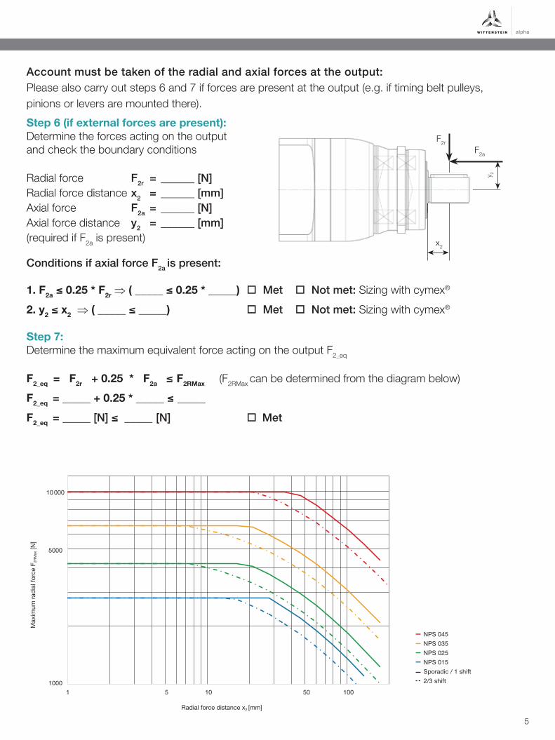
Account must be taken of the radial and axial forces at the output:Please also carry out steps 6 and 7 if forces are present at the output (e.g. if timing belt pulleys, pinions or levers are mounted there).
Conditions if axial force F2a is present:
1. F2a ≤ 0.25 * F2r ⇒ ( _____ ≤ 0.25 * _____) Met Not met: Sizing with cymex®
2. y2 ≤ x2 ⇒ ( _____ ≤ _____) Met Not met: Sizing with cymex®
Step 6 (if external forces are present): Determine the forces acting on the output and check the boundary conditions
Radial force F2r = ______ [N]Radial force distance x2 = ______ [mm]Axial force F2a = ______ [N]Axial force distance y2 = ______ [mm] (required if F2a is present)
Operating mode factor KM
Siz
ing
fact
or f a
Sporadic (operating time < 1h/day)1 shift2/3 shift
6
5
4
3
2
11 1.2 1.4 1.6 1.8 2 2.2 2.4 2.6 2.8 3
1.6
1.9
1.61.9
3.0
3.6
4.1
3.5
2.22.5
4.0
4.8 4.8
5.7
3.0
2.6
3.1
1.0
Radial force distance x2 [mm]
Max
imum
radi
al fo
rce
F 2R
Max
[N]
NPS 045NPS 035NPS 025NPS 015Sporadic / 1 shift2/3 shift
Step 7: Determine the maximum equivalent force acting on the output F2_eq
F2_eq = F2r + 0.25 * F2a ≤ F2RMax (F2RMax can be determined from the diagram below)
F2_eq = _____ + 0.25 * _____ ≤ _____
F2_eq = _____ [N] ≤ _____ [N] Met
5
Ratio a) i
Maximum torque MF T2α Nm
in.lb
Maximum torque HIGH TORQUE – MA T2α Nm
in.lb
Emergency stop torque b) T2Not Nm
in.lb
Nominal input speed c) n1N min-1
Max. input speed n1Max min-1
Max. torsional backlash jt arcmin
Max. axial force d) F2AMax N
lbf
Max. radial force d) F2RMax N
lbf
Weight incl. standard adapter plate e) m kg
lbm
Operating noise f) LPA dB(A)
Max. permitted housing temperature °C +90
F +194
Ambient temperature °C -15 to +40
F +5 to +104
Lubrication Lubricated for life
Paint Housing: pearl dark grey / Drive-Side: Innovation Blue
Direction of rotation Motor and gearhead same direction
Type of protection IP 65
Moment of inertia(relates to the drive)
Clamping hub diameter [mm]^
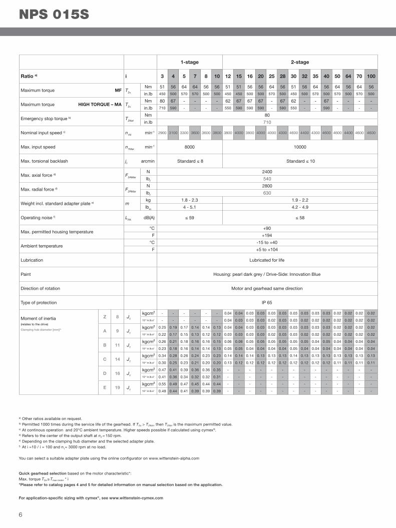
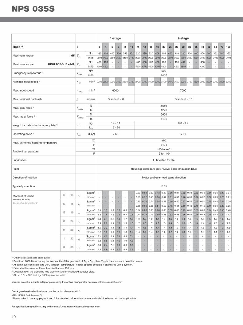
a) Other ratios available on request.b) Permitted 1000 times during the service life of the gearhead. If T2α > T2Not, then T2Not is the maximum permitted value.c) At continous operation and 20°C ambient temperature. Higher speeds possible if calculated using cymex®. d) Refers to the center of the output shaft at n2 = 150 rpm.e) Depending on the clamping hub diameter and the selected adapter plate.f) At i =10 / i = 100 and n1= 3000 rpm at no load.
You can select a suitable adapter plate using the online configurator on www.wittenstein-alpha.com
Quick gearhead selection based on the motor characteristic*:Max. torque T2α ≥ Tmax motor * i*Please refer to catalog pages 4 and 5 for detailed information on manual selection based on the application.
For application-specific sizing with cymex®, see www.wittenstein-cymex.com
NPS 015S
1-stage 2-stage
3 4 5 7 8 10 12 15 16 20 25 28 30 32 35 40 50 64 70 100
51 56 64 64 56 56 51 51 56 56 64 56 51 56 64 56 64 56 64 56450 500 570 570 500 500 450 450 500 500 570 500 450 500 570 500 570 500 570 500
80 67 - - - - 62 67 67 67 - 67 62 - - 67 - - - -710 590 - - - - 550 590 590 590 - 590 550 - - 590 - - - -
80
710
2900 3100 3300 3600 3600 3800 3800 4000 3800 4000 4000 4300 4600 4400 4300 4600 4600 4400 4600 4600
8000 10000
Standard ≤ 8 Standard ≤ 10
2400
540
2800
630
1.8 - 2.3 1.9 - 2.2
4 - 5.1 4.2 - 4.9
≤ 59 ≤ 58
Z 8 J1 kgcm² - - - - - - 0.04 0.04 0.03 0.03 0.03 0.03 0.03 0.03 0.03 0.03 0.02 0.02 0.02 0.02
10-3 in.lb.s2 - - - - - - 0.04 0.03 0.03 0.03 0.02 0.03 0.03 0.02 0.02 0.02 0.02 0.02 0.02 0.02
A 9 J1 kgcm² 0.25 0.19 0.17 0.14 0.14 0.13 0.04 0.04 0.03 0.03 0.03 0.03 0.03 0.03 0.03 0.03 0.02 0.02 0.02 0.02
10-3 in.lb.s2 0.22 0.17 0.15 0.13 0.12 0.12 0.03 0.03 0.03 0.03 0.02 0.03 0.03 0.02 0.02 0.02 0.02 0.02 0.02 0.02
B 11 J1 kgcm² 0.26 0.21 0.18 0.16 0.16 0.15 0.06 0.06 0.05 0.05 0.05 0.05 0.05 0.05 0.04 0.05 0.04 0.04 0.04 0.04
10-3 in.lb.s2 0.23 0.18 0.16 0.14 0.14 0.13 0.05 0.05 0.04 0.04 0.04 0.04 0.05 0.04 0.04 0.04 0.04 0.04 0.04 0.04
C 14 J1 kgcm² 0.34 0.28 0.26 0.24 0.23 0.23 0.14 0.14 0.14 0.13 0.13 0.13 0.14 0.13 0.13 0.13 0.13 0.13 0.13 0.13
10-3 in.lb.s2 0.30 0.25 0.23 0.21 0.20 0.20 0.13 0.12 0.12 0.12 0.12 0.12 0.12 0.12 0.12 0.12 0.11 0.11 0.11 0.11
D 16 J1 kgcm² 0.47 0.41 0.39 0.36 0.36 0.35 - - - - - - - - - - - - - -
10-3 in.lb.s2 0.41 0.36 0.34 0.32 0.32 0.31 - - - - - - - - - - - - - -
E 19 J1 kgcm² 0.55 0.49 0.47 0.45 0.44 0.44 - - - - - - - - - - - - - -
10-3 in.lb.s2 0.49 0.44 0.41 0.39 0.39 0.39 - - - - - - - - - - - - - -
6
alpha
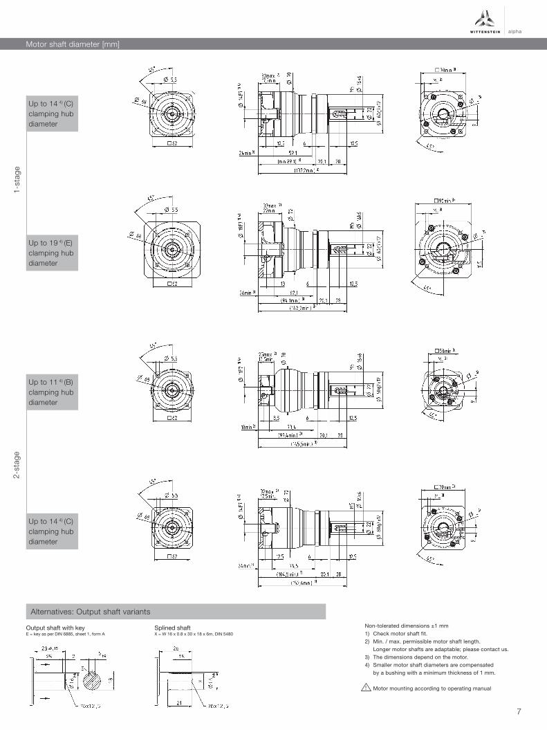
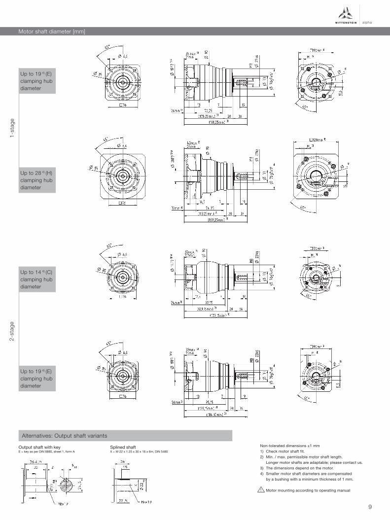
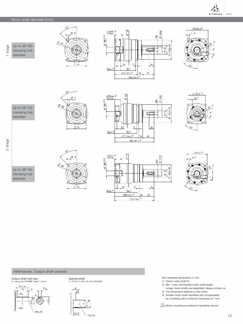
Motor shaft diameter [mm]
!
Non-tolerated dimensions ±1 mm1) Check motor shaft fit.2) Min. / max. permissible motor shaft length. Longer motor shafts are adaptable; please contact us.3) The dimensions depend on the motor.4) Smaller motor shaft diameters are compensated by a bushing with a minimum thickness of 1 mm.
Motor mounting according to operating manual
Up to 19 4) (E) clamping hub diameter
Up to 14 4) (C) clamping hub diameter
Up to 14 4) (C) clamping hub diameter
Up to 11 4) (B) clamping hub diameter
Splined shaftX = W 16 x 0.8 x 30 x 18 x 6m, DIN 5480
1-st
age
2-st
age
Output shaft with keyE = key as per DIN 6885, sheet 1, form A
Alternatives: Output shaft variants
7
Ratio a) i
Maximum torque MF T2α Nm
in.lb
Maximum torque HIGH TORQUE – MA T2α Nm
in.lb
Emergency stop torque b) T2Not Nm
in.lb
Nominal input speed c) n1N min-1
Max. input speed n1Max min-1
Max. torsional backlash jt arcmin
Max. axial force d) F2AMax N
lbf
Max. radial force d) F2RMax N
lbf
Weight incl. standard adapter plate e) m kg
lbm
Operating noise f) LPA dB(A)
Max. permitted housing temperature °C +90
F +194
Ambient temperature °C -15 to +40
F +5 to +104
Lubrication Lubricated for life
Paint Housing: pearl dark grey / Drive-Side: Innovation Blue
Direction of rotation Motor and gearhead same direction
Type of protection IP 65
Moment of inertia(relates to the drive)
Clamping hub diameter [mm]^
a) Other ratios available on request.b) Permitted 1000 times during the service life of the gearhead. If T2α > T2Not, then T2Not is the maximum permitted value.c) At continous operation and 20°C ambient temperature. Higher speeds possible if calculated using cymex®. d) Refers to the center of the output shaft at n2 = 150 rpm.e) Depending on the clamping hub diameter and the selected adapter plate.f) At i =10 / i = 100 and n1= 3000 rpm at no load.
You can select a suitable adapter plate using the online configurator on www.wittenstein-alpha.com
Quick gearhead selection based on the motor characteristic*:Max. torque T2α ≥ Tmax motor * i*Please refer to catalog pages 4 and 5 for detailed information on manual selection based on the application.
For application-specific sizing with cymex®, see www.wittenstein-cymex.com
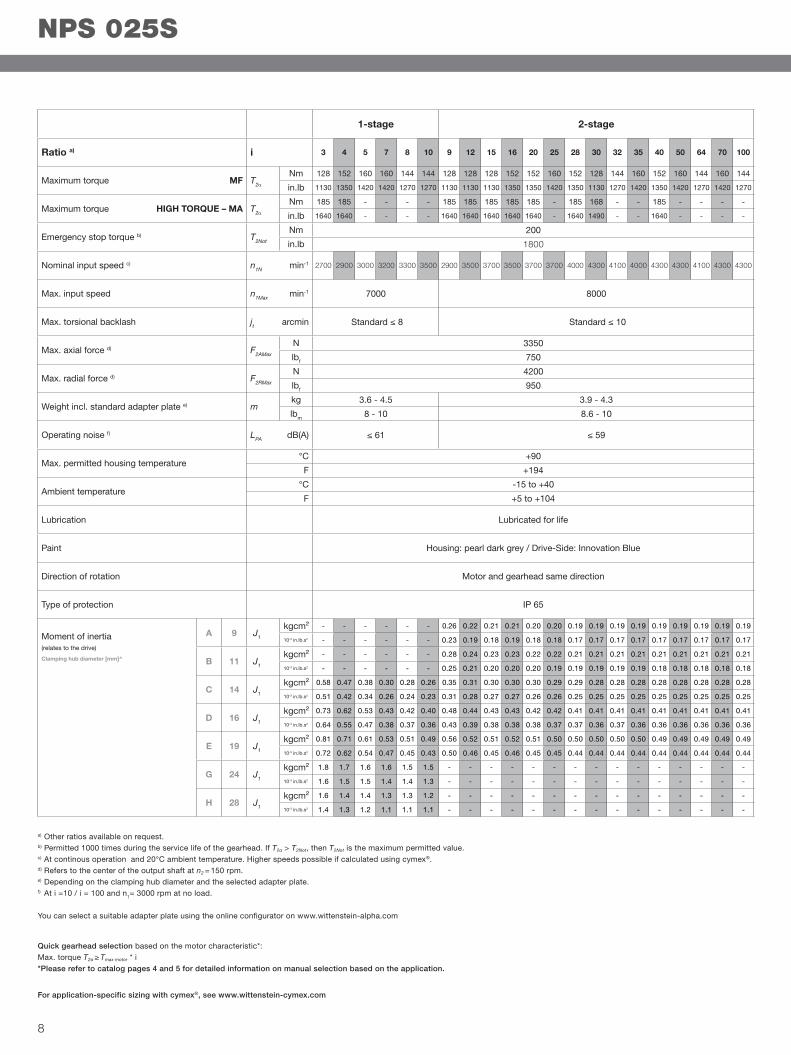
NPS 025S
1-stage 2-stage
3 4 5 7 8 10 9 12 15 16 20 25 28 30 32 35 40 50 64 70 100
128 152 160 160 144 144 128 128 128 152 152 160 152 128 144 160 152 160 144 160 144
1130 1350 1420 1420 1270 1270 1130 1130 1130 1350 1350 1420 1350 1130 1270 1420 1350 1420 1270 1420 1270
185 185 - - - - 185 185 185 185 185 - 185 168 - - 185 - - - -
1640 1640 - - - - 1640 1640 1640 1640 1640 - 1640 1490 - - 1640 - - - -
200
1800
2700 2900 3000 3200 3300 3500 2900 3500 3700 3500 3700 3700 4000 4300 4100 4000 4300 4300 4100 4300 4300
7000 8000
Standard ≤ 8 Standard ≤ 10
3350
750
4200
950
3.6 - 4.5 3.9 - 4.3
8 - 10 8.6 - 10
≤ 61 ≤ 59
A 9 J1 kgcm² - - - - - - 0.26 0.22 0.21 0.21 0.20 0.20 0.19 0.19 0.19 0.19 0.19 0.19 0.19 0.19 0.19
10-3 in.lb.s2 - - - - - - 0.23 0.19 0.18 0.19 0.18 0.18 0.17 0.17 0.17 0.17 0.17 0.17 0.17 0.17 0.17
B 11 J1 kgcm² - - - - - - 0.28 0.24 0.23 0.23 0.22 0.22 0.21 0.21 0.21 0.21 0.21 0.21 0.21 0.21 0.21
10-3 in.lb.s2 - - - - - - 0.25 0.21 0.20 0.20 0.20 0.19 0.19 0.19 0.19 0.19 0.18 0.18 0.18 0.18 0.18
C 14 J1 kgcm² 0.58 0.47 0.38 0.30 0.28 0.26 0.35 0.31 0.30 0.30 0.30 0.29 0.29 0.28 0.28 0.28 0.28 0.28 0.28 0.28 0.28
10-3 in.lb.s2 0.51 0.42 0.34 0.26 0.24 0.23 0.31 0.28 0.27 0.27 0.26 0.26 0.25 0.25 0.25 0.25 0.25 0.25 0.25 0.25 0.25
D 16 J1 kgcm² 0.73 0.62 0.53 0.43 0.42 0.40 0.48 0.44 0.43 0.43 0.42 0.42 0.41 0.41 0.41 0.41 0.41 0.41 0.41 0.41 0.41
10-3 in.lb.s2 0.64 0.55 0.47 0.38 0.37 0.36 0.43 0.39 0.38 0.38 0.38 0.37 0.37 0.36 0.37 0.36 0.36 0.36 0.36 0.36 0.36
E 19 J1 kgcm² 0.81 0.71 0.61 0.53 0.51 0.49 0.56 0.52 0.51 0.52 0.51 0.50 0.50 0.50 0.50 0.50 0.49 0.49 0.49 0.49 0.49
10-3 in.lb.s2 0.72 0.62 0.54 0.47 0.45 0.43 0.50 0.46 0.45 0.46 0.45 0.45 0.44 0.44 0.44 0.44 0.44 0.44 0.44 0.44 0.44
G 24 J1 kgcm² 1.8 1.7 1.6 1.6 1.5 1.5 - - - - - - - - - - - - - - -
10-3 in.lb.s2 1.6 1.5 1.5 1.4 1.4 1.3 - - - - - - - - - - - - - - -
H 28 J1 kgcm² 1.6 1.4 1.4 1.3 1.3 1.2 - - - - - - - - - - - - - - -
10-3 in.lb.s2 1.4 1.3 1.2 1.1 1.1 1.1 - - - - - - - - - - - - - - -
8
alpha
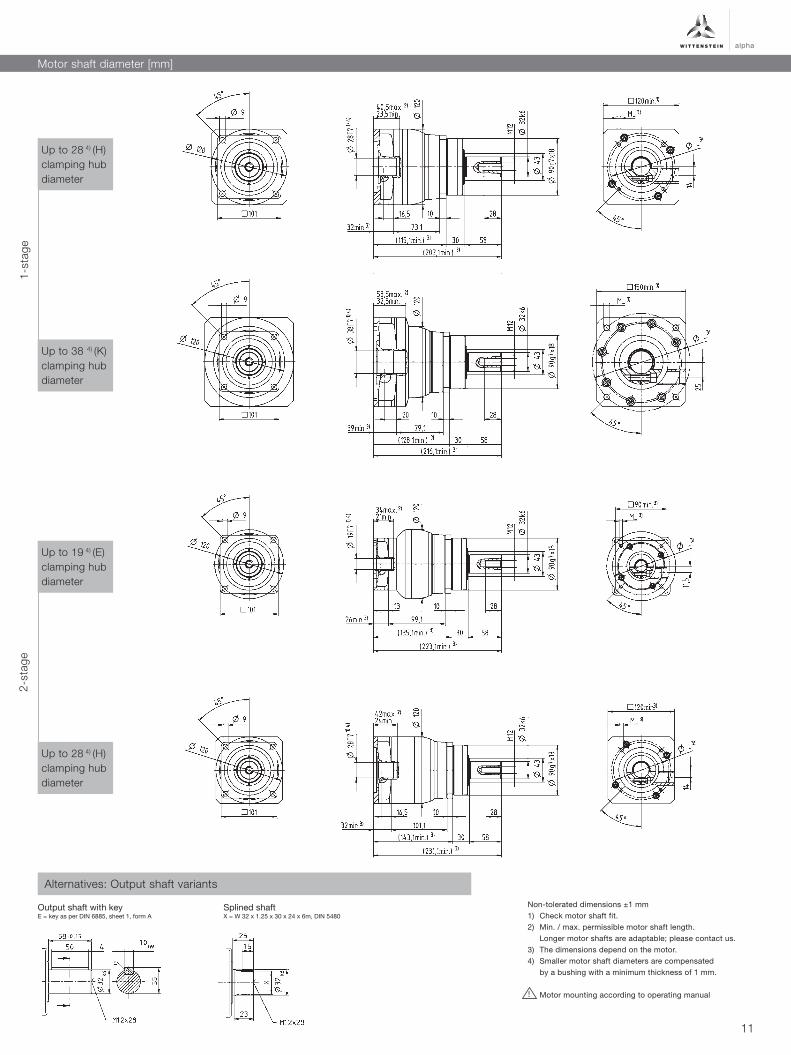
Motor shaft diameter [mm]
!
Non-tolerated dimensions ±1 mm1) Check motor shaft fit.2) Min. / max. permissible motor shaft length. Longer motor shafts are adaptable; please contact us.3) The dimensions depend on the motor.4) Smaller motor shaft diameters are compensated by a bushing with a minimum thickness of 1 mm.
Motor mounting according to operating manual
Up to 28 4) (H) clamping hub diameter
Up to 19 4) (E) clamping hub diameter
Up to 19 4) (E) clamping hub diameter
Up to 14 4) (C) clamping hub diameter
Splined shaftX = W 22 x 1.25 x 30 x 16 x 6m, DIN 5480
1-st
age
2-st
age
Output shaft with keyE = key as per DIN 6885, sheet 1, form A
Alternatives: Output shaft variants
9
Ratio a) i
Maximum torque MF T2α Nm
in.lb
Maximum torque HIGH TORQUE – MA T2α Nm
in.lb
Emergency stop torque b) T2Not Nm
in.lb
Nominal input speed c) n1N min-1
Max. input speed n1Max min-1
Max. torsional backlash jt arcmin
Max. axial force d) F2AMax N
lbf
Max. radial force d) F2RMax N
lbf
Weight incl. standard adapter plate e) m kg
lbm
Operating noise f) LPA dB(A)
Max. permitted housing temperature °C +90
F +194
Ambient temperature °C -15 to +40
F +5 to +104
Lubrication Lubricated for life
Paint Housing: pearl dark grey / Drive-Side: Innovation Blue
Direction of rotation Motor and gearhead same direction
Type of protection IP 65
Moment of inertia(relates to the drive)
Clamping hub diameter [mm]^
a) Other ratios available on request.b) Permitted 1000 times during the service life of the gearhead. If T2α > T2Not, then T2Not is the maximum permitted value.c) At continous operation and 20°C ambient temperature. Higher speeds possible if calculated using cymex®. d) Refers to the center of the output shaft at n2 = 150 rpm.e) Depending on the clamping hub diameter and the selected adapter plate.f) At i =10 / i = 100 and n1= 3000 rpm at no load.
You can select a suitable adapter plate using the online configurator on www.wittenstein-alpha.com
Quick gearhead selection based on the motor characteristic*:Max. torque T2α ≥ Tmax motor * i*Please refer to catalog pages 4 and 5 for detailed information on manual selection based on the application.
For application-specific sizing with cymex®, see www.wittenstein-cymex.com
NPS 035S
1-stage 2-stage
3 4 5 7 8 10 9 12 15 16 20 25 28 30 32 35 40 50 64 70 100
320 408 400 400 352 352 320 320 320 408 408 400 408 320 408 400 408 400 352 400 352
2800 3600 3500 3500 3100 3100 2800 2800 2800 3600 3600 3500 3600 2800 3600 3500 3600 3500 3100 3500 3100
480 480 - - - - 480 480 480 480 480 - 480 432 - - 480 - - - -
4200 4200 - - - - 4200 4200 4200 4200 4200 - 4200 3800 - - 4200 - - - -
500
4400
2000 2200 2300 2500 2600 2700 2700 3300 3400 3300 3400 3400 3600 3900 3700 3600 3900 3900 3700 3900 3900
6000 7000
Standard ≤ 8 Standard ≤ 10
5650
1270
6600
1490
8.4 - 11 8.8 - 9.9
19 - 24
≤ 65 ≤ 61
C 14 J1 kgcm² - - - - - - 0.60 0.59 0.60 0.43 0.42 0.36 0.37 0.52 0.38 0.32 0.36 0.31 0.26 0.27 0.24
10-3 in.lb.s2 - - - - - - 0.53 0.52 0.53 0.38 0.37 0.31 0.33 0.46 0.33 0.28 0.32 0.27 0.23 0.23 0.21
D 16 J1 kgcm² - - - - - - 0.75 0.74 0.74 0.58 0.57 0.50 0.50 0.67 0.52 0.45 0.51 0.46 0.40 0.41 0.39
10-3 in.lb.s2 - - - - - - 0.66 0.66 0.66 0.51 0.50 0.45 0.44 0.59 0.46 0.40 0.45 0.41 0.36 0.37 0.35
E 19 J1 kgcm² 2.5 1.7 1.3 1.0 0.9 0.9 0.84 0.83 0.83 0.66 0.65 0.59 0.60 0.75 0.61 0.55 0.60 0.54 0.49 0.50 0.48
10-3 in.lb.s2 2.2 1.5 1.2 0.9 0.8 0.8 0.74 0.73 0.73 0.59 0.58 0.52 0.53 0.66 0.54 0.49 0.53 0.48 0.43 0.44 0.42
G 24 J1 kgcm² 3.3 2.4 2.1 1.8 1.7 1.6 1.9 1.9 1.9 1.7 1.7 1.6 1.6 1.8 1.6 1.6 1.6 1.6 1.5 1.5 1.5
10-3 in.lb.s2 2.9 2.2 1.9 1.6 1.5 1.5 1.7 1.6 1.7 1.5 1.5 1.4 1.5 1.6 1.5 1.4 1.4 1.4 1.3 1.4 1.3
H 28 J1 kgcm² 3.0 2.2 1.8 1.5 1.4 1.4 1.6 1.6 1.6 1.4 1.4 1.3 1.3 1.5 1.4 1.3 1.3 1.3 1.2 1.2 1.2
10-3 in.lb.s2 2.7 1.9 1.6 1.3 1.3 1.2 1.4 1.4 1.4 1.2 1.2 1.2 1.2 1.3 1.2 1.1 1.2 1.1 1.1 1.1 1.1
I 32 J1 kgcm² 7.1 6.2 5.9 5.6 5.5 5.4 - - - - - - - - - - - - - - -
10-3 in.lb.s2 6.3 5.5 5.2 4.9 4.9 4.8 - - - - - - - - - - - - - - -
K 38 J1 kgcm² 8.3 7.4 7.1 6.7 6.6 6.6 - - - - - - - - - - - - - - -
10-3 in.lb.s2 7.3 6.6 6.3 6.0 5.9 5.8 - - - - - - - - - - - - - - -
10
alpha
Motor shaft diameter [mm]
!
Non-tolerated dimensions ±1 mm1) Check motor shaft fit.2) Min. / max. permissible motor shaft length. Longer motor shafts are adaptable; please contact us.3) The dimensions depend on the motor.4) Smaller motor shaft diameters are compensated by a bushing with a minimum thickness of 1 mm.
Motor mounting according to operating manual
Up to 38 4) (K) clamping hub diameter
Up to 28 4) (H) clamping hub diameter
Up to 28 4) (H) clamping hub diameter
Up to 19 4) (E) clamping hub diameter
Splined shaftX = W 32 x 1.25 x 30 x 24 x 6m, DIN 5480
1-st
age
2-st
age
Output shaft with keyE = key as per DIN 6885, sheet 1, form A
Alternatives: Output shaft variants
11
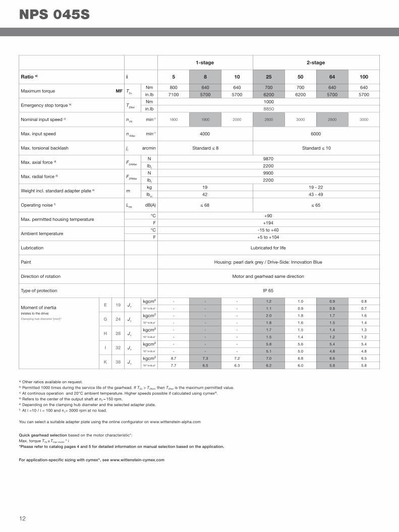
a) Other ratios available on request.b) Permitted 1000 times during the service life of the gearhead. If T2α > T2Not, then T2Not is the maximum permitted value.c) At continous operation and 20°C ambient temperature. Higher speeds possible if calculated using cymex®. d) Refers to the center of the output shaft at n2 = 150 rpm.e) Depending on the clamping hub diameter and the selected adapter plate.f) At i =10 / i = 100 and n1= 3000 rpm at no load.
You can select a suitable adapter plate using the online configurator on www.wittenstein-alpha.com
Quick gearhead selection based on the motor characteristic*:Max. torque T2α ≥ Tmax motor * i*Please refer to catalog pages 4 and 5 for detailed information on manual selection based on the application.
For application-specific sizing with cymex®, see www.wittenstein-cymex.com
Ratio a) i
Maximum torque MF T2α Nm
in.lb
Emergency stop torque b) T2Not Nm
in.lb
Nominal input speed c) n1N min-1
Max. input speed n1Max min-1
Max. torsional backlash jt arcmin
Max. axial force d) F2AMax N
lbf
Max. radial force d) F2RMax N
lbf
Weight incl. standard adapter plate e) mkg
lbm
Operating noise f) LPA dB(A)
Max. permitted housing temperature °C +90
F +194
Ambient temperature °C -15 to +40
F +5 to +104
Lubrication Lubricated for life
Paint Housing: pearl dark grey / Drive-Side: Innovation Blue
Direction of rotation Motor and gearhead same direction
Type of protection IP 65
Moment of inertia(relates to the drive)
Clamping hub diameter [mm]^
NPS 045S
1-stage 2-stage
5 8 10 25 50 64 100
800 640 640 700 700 640 640
7100 5700 5700 6200 6200 5700 5700
1000
8850
1800 1900 2000 2600 3000 2900 3000
4000 6000
Standard ≤ 8 Standard ≤ 10
9870
2200
9900
2200
19 19 - 22
42 43 - 49
≤ 68 ≤ 65
E 19 J1 kgcm² - - - 1.2 1.0 0.9 0.8
10-3 in.lb.s2 - - - 1.1 0.9 0.8 0.7
G 24 J1 kgcm² - - - 2.0 1.8 1.7 1.6
10-3 in.lb.s2 - - - 1.8 1.6 1.5 1.4
H 28 J1 kgcm² - - - 1.7 1.5 1.4 1.3
10-3 in.lb.s2 - - - 1.5 1.4 1.2 1.2
I 32 J1 kgcm² - - - 5.8 5.6 5.4 5.4
10-3 in.lb.s2 - - - 5.1 5.0 4.8 4.8
K 38 J1 kgcm² 8.7 7.3 7.2 7.0 6.8 6.6 6.5
10-3 in.lb.s2 7.7 6.5 6.3 6.2 6.0 5.8 5.8
12
alpha
Motor shaft diameter [mm]
!
Non-tolerated dimensions ±1 mm1) Check motor shaft fit.2) Min. / max. permissible motor shaft length. Longer motor shafts are adaptable; please contact us.3) The dimensions depend on the motor.4) Smaller motor shaft diameters are compensated by a bushing with a minimum thickness of 1 mm.
Motor mounting according to operating manual
Up to 28 4) (H) clamping hub diameter
Up to 38 4) (K) clamping hub diameter
Up to 38 4) (K) clamping hub diameter
Splined shaftX = W 40 x 2 x 30 x 18 x 6m, DIN 5480
1-st
age
2-st
age
Output shaft with keyE = key as per DIN 6885, sheet 1, form A
Alternatives: Output shaft variants
13
Glossary
Equivalent force at the output (F2_eq)
The equivalent force F2_eq at the outputdescribes the decisive forces for gear-head selection.
Equivalent application torque (T2_eq)
The equivalent application torque T2_eq
describes the decisive torque for gear-head selection.
Sizing factor (fa)
The siz ing factor f a descr ibes the influence of the daily operating time and the operating mode factor on the appli-cation torque.
Operating mode factor (KM)
The operating mode factor KM describes the influence of the duty cycle, the num-ber of cycles and the dynamics on the ap-plication torque.
Moment of inertia (relates to the drive) (J)
The mass moment of inertia J is a measure of the effort applied by an object to maintain its momentary con-dition (at rest or moving).
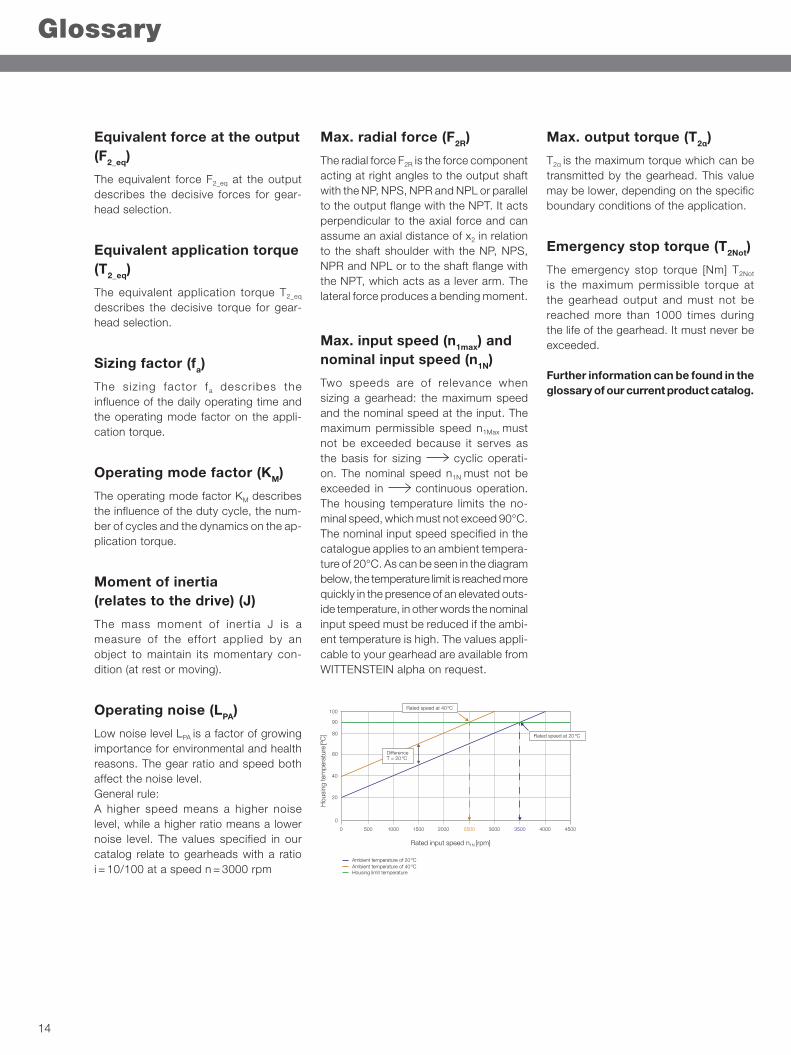
Operating noise (LPA)
Low noise level LPA is a factor of growing importance for environmental and health reasons. The gear ratio and speed both affect the noise level.General rule:A higher speed means a higher noise level, while a higher ratio means a lower noise level. The values specified in our catalog relate to gearheads with a ratio i = 10/100 at a speed n = 3000 rpm
Max. radial force (F2R)
The radial force F2R is the force component acting at right angles to the output shaft with the NP, NPS, NPR and NPL or parallel to the output flange with the NPT. It acts perpendicular to the axial force and can assume an axial distance of x2 in relation to the shaft shoulder with the NP, NPS, NPR and NPL or to the shaft flange with the NPT, which acts as a lever arm. The lateral force produces a bending moment.
Max. input speed (n1max) and nominal input speed (n1N)
Two speeds are of relevance when sizing a gearhead: the maximum speed and the nominal speed at the input. The maximum permissible speed n1Max must not be exceeded because it serves as the basis for sizing cyclic operati-on. The nominal speed n1N must not be exceeded in continuous operation. The housing temperature limits the no-minal speed, which must not exceed 90°C. The nominal input speed specified in the catalogue applies to an ambient tempera-ture of 20°C. As can be seen in the diagram below, the temperature limit is reached more quickly in the presence of an elevated outs-ide temperature, in other words the nominal input speed must be reduced if the ambi-ent temperature is high. The values appli-cable to your gearhead are available from WITTENSTEIN alpha on request.
Max. output torque (T2α)
T2α is the maximum torque which can be transmitted by the gearhead. This value may be lower, depending on the specific boundary conditions of the application.
Emergency stop torque (T2Not)
The emergency stop torque [Nm] T2Not
is the maximum permissible torque at the gearhead output and must not be reached more than 1000 times during the life of the gearhead. It must never be exceeded.
Further information can be found in the glossary of our current product catalog.
100
500 1000 1500 2000 2500 3000 3500 4000 4500
90
80
60
40
20
0
0
Rated input speed n1N [rpm]
Hou
sing
tem
pera
ture
[ºC
]
Ambient temperature of 20 ºCAmbient temperature of 40 ºCHousing limit temperature
Di�erenceT = 20 ºC
Rated speed at 20 ºC
Rated speed at 40 ºC
14
alpha
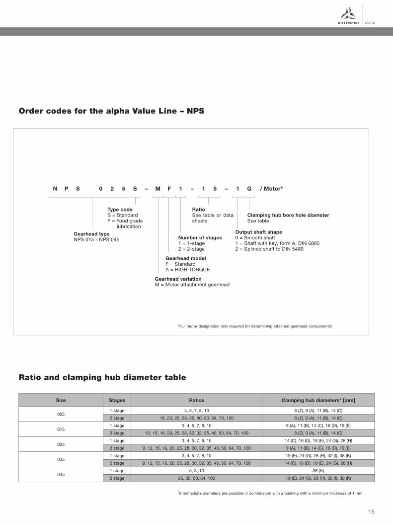
Order codes for the alpha Value Line – NPS
Gearhead typeNPS 015 - NPS 045
Output shaft shape0 = Smooth shaft1 = Shaft with key, form A, DIN 68852 = Splined shaft to DIN 5480
Number of stages1 = 1-stage2 = 2-stage
Gearhead modelF = StandardA = HIGH TORQUE
Gearhead variationM = Motor attachment gearhead
RatioSee table or data sheets
Clamping hub bore hole diameterSee table
N P S 0 2 5 S – M F 1 – 1 5 – 1 G / Motor*
Size Stages Ratios Clamping hub diameters* [mm]
0051 stage 4, 5, 7, 8, 10 8 (Z), 9 (A), 11 (B), 14 (C)
2 stage 16, 20, 25, 28, 35, 40, 50, 64, 70, 100 8 (Z), 9 (A), 11 (B), 14 (C)
0151 stage 3, 4, 5, 7, 8, 10 9 (A), 11 (B), 14 (C), 16 (D), 19 (E)
2 stage 12, 15, 16, 20, 25, 28, 30, 32, 35, 40, 50, 64, 70, 100 8 (Z), 9 (A), 11 (B), 14 (C)
0251 stage 3, 4, 5, 7, 8, 10 14 (C), 16 (D), 19 (E), 24 (G), 28 (H)
2 stage 9, 12, 15, 16, 20, 25, 28, 30, 32, 35, 40, 50, 64, 70, 100 9 (A), 11 (B), 14 (C), 16 (D), 19 (E)
0351 stage 3, 4, 5, 7, 8, 10 19 (E), 24 (G), 28 (H), 32 (I), 38 (K)
2 stage 9, 12, 15, 16, 20, 25, 28, 30, 32, 35, 40, 50, 64, 70, 100 14 (C), 16 (D), 19 (E), 24 (G), 28 (H)
0451 stage 5, 8, 10 38 (K)
2 stage 25, 32, 50, 64, 100 19 (E), 24 (G), 28 (H), 32 (I), 38 (K)
Ratio and clamping hub diameter table
*Intermediate diameters are possible in combination with a bushing with a minimum thickness of 1 mm.
*Full motor designation only required for determining attached gearhead components!
Type codeS = StandardF = Food grade lubrication
15
Rückseite „Standard“
WITTENSTEIN alpha GmbH · Walter-Wittenstein-Straße 1 · 97999 Igersheim · Tel. +49 7931 493-0 · [email protected]
www.wittenstein-alpha.com
WITTENSTEIN alpha – intelligent drive systems
WIT
TEN
STE
IN a
lpha
_Val
ue_L
ine_
NP
S_e
n_04
_201
8_I
Tech
nica
l cha
nges
res
erve
d