Embed Size (px)
Citation preview

The First Name In Corrosion Resistant Valves
Aloyco Corrosion Resistant Valves

T: 562-426-2531 • F: 562-490-9546 • www.craneenergy.com 3
Figure No. Valve Type Pressure Class End Connection Material Available Size Range Catalog Page
90 Gate, RS 200 CWP Threaded CF8M 1⁄2" - 2" 5
190 Gate, NRS 200 CWP Threaded CF8M 1⁄2" - 2" 5
110 Gate, OS&Y 150 Threaded CF3M 1⁄2" - 2" 6
114 Gate, OS&Y 150 Socket Weld CF3M 1⁄2" - 2" 6
117, 117F Gate, OS&Y 150 Flanged CF8M 1⁄2" - 24" 7
2110 Gate, OS&Y 300 Threaded CF3M 1⁄2" - 2" 8
2114 Gate, OS&Y 300 Socket Weld CF3M 1⁄2" - 2" 8
2117, 2117F Gate, OS&Y 300 Flanged CF8M 1⁄2" - 24" 9
4210 Gate, OS&Y 600 Threaded CF3M 1⁄2" - 2" 10
4214 Gate, OS&Y 600 Socket Weld CF3M 1⁄2" - 2" 10
4117 Gate, OS&Y 600 Flanged CF8M 2" - 12" 11
40 Globe 200 CWP Threaded CF8M 1⁄2" - 2" 12
310 Globe 150 Threaded CF3M 1⁄2" - 2" 13
314 Globe 150 Socket Weld CF3M 1⁄2" - 2" 13
317 Globe 150 Flanged CF8M 1⁄2" - 12" 14
2310 Globe 300 Threaded CF3M 1⁄2" - 2" 15
2314 Globe 300 Socket Weld CF3M 1⁄2" - 2" 15
2317 Globe 300 Flanged CF8M 1⁄2" - 8" 16
4310 Globe 600 Threaded CF3M 1⁄2" - 2" 17
4314 Globe 600 Socket Weld CF3M 1⁄2" - 2" 17
4317 Globe 600 Flanged CF8M 1⁄2" - 6" 18
49 Swing Check 200 CWP Threaded CF8M 1⁄2" - 2" 19
370 Swing Check 150 Threaded CF3M 1⁄2" - 2" 20
374 Swing Check 150 Socket Weld CF3M 1⁄2" - 2" 20
377 Swing Check 150 Flanged CF8M 1⁄2" - 24" 21
2370 Swing Check 300 Threaded CF3M 1⁄2" - 2" 22
2374 Swing Check 300 Socket Weld CF3M 1⁄2" - 2" 22
2377 Swing Check 300 Flanged CF8M 1⁄2" - 24" 23
4370 Swing Check 600 Threaded CF3M 1⁄2" - 2" 24
4374 Swing Check 600 Socket Weld CF3M 1⁄2" - 2" 24
4377 Swing Check 600 Flanged CF8M 1⁄2" - 12" 25
9431-S-LL Ball - 2 pc 2000 CWP Threaded CF8M 1⁄4" - 2" 26
Stainless Steel ValvesGeneral Index
T: 256-775-3800 • F: 256-775-3860 • www.craneenergy.com

T: 256-775-3800 • F: 256-775-3860 • www.craneenergy.com4
How to Specify and Order the Correct ValvesThis catalog has been published to assist you in choosing the correct valve for a vast number of piping conditions. The Aloyco product line makes available to you a very broad choice of valves. These valves are described in this catalog.
Care should be taken to select the most suitable valves for your service(s). Exact specification of each valve should be made to avoid possible ambiguity. When requesting quota-tions and/or ordering the product a fully adequate description should be made.
Selecting the Valve SizeNominal size of the pipeline into which the valve will be placed must be determined.
Valve MaterialThe following facts should be considered in determining the correct valve material:
• themediumormediawhichwillbecontrolled• thetemperaturerangeofthelinemedium(media)• thepressurerangetowhichthevalvewillbesubjected• possibleatmosphericconditionswhichmayaffect the valve• possibleextraordinarystressestowhichthevalvewill besubjected• safetystandardsand/orpipingcodeswhichmustbemet
Type of ValveWhat is the control function of the valve? Each valve con-figuration has been developed to perform certain control functions. Do not expect one type of valve to perform all the valvingjobsinasystem.
Pressure-Temperature RatingsPlease pay careful attention that the pressure-temperature ratings of a particular valve are in keeping with the require-ments of the service. Pay especially careful attention to the packing and gasket materials as this may limit the rating as is the case with PTFE used as the standard in Aloyco valves. We offer graphite packing and gaskets in many sizes and pressure classes. Specify graphite or alternative packing and/or gasket materials as necessary to meet or exceed your service requirements.
How To OrderStainless Steel Valves
Valve and ConnectionsConsiderations as to pipeline integrity, future maintenance, corrosion factors, field assembly, weight and safety should be given in determining the method of connecting the valve in the pipeline.
Method of OperationThe means by which the valve is operated as supplied are shown for the valves in this catalog. Many optional operating devices are regularly supplied by Aloyco.
Ordering the ValvePlease state the following information when ordering a valve in order to avoid unnecessary delays and to insure we supply you with the valve you have requested.
1. Valve size.2. Pressure boundary material - metallurgy of the castings
and components.3. Type of valve - gate, globe, check, etc.4. End connection including wall thickness of connecting
pipe if weld end and any special flange facings or finishes.5. Any material deviations from standard - packing, gasket,
bolting, etc.6. Any accessories - acid shield, locking devices, chain opera-
tion, etc.7. Manual or power actuators, please include details of requirements.8. For convenience in ordering, specify by figure number.
Contact Aloyco for additional assistance in valve selection.
Due to our policy of continuous product improvement, Aloyco reserves the right to change designs, materials, or specifications without notice.

T: 562-426-2531 • F: 562-490-9546 • www.craneenergy.com 5
Dimensions and Weights Dimensions (inches) Valve Weight (lbs) A B (open) C Size 90 190 90 190 90 190 90 190 ½ 1.0 0.9 2.01 2.1 5.1 3.8 2.6 2.1 ¾ 1.3 1.5 2.20 2.3 5.8 4.6 2.6 2.6 1 1.7 2.5 2.48 2.8 6.6 5.3 3.0 2.8 1 ½ 3.4 3.2 3.01 3.6 9.4 7.3 3.6 3.6 2 5.2 7.0 3.41 3.9 11.0 8.4 4.0 4.1
200 CWP • Threaded Bonnet • Solid Wedge Disc
Figure 90Rising Stem
Figure 190Non-Rising Stem
Size Range:
½ through 2 inches
Design Features:•ThreadedEnds• IntegralSeat• Figure190-InsideScrew/Non-risingStem
Pressure Temperature Ratings:200 psi @ -20 to 100°F135 psi @ 500°F
IndustryStandards Threaded Ends ASME B1.20.1 End-to-End Manufacturer's Standard
Fig. 90
Stainless Steel Gate ValvesFIGURES90 • 190
Materials of Construction 1 Body ASTM A351 CF8M 2 Bonnet ASTM A351 CF8M 3 Disc ASTM A351 CF8M 4 Stem 316 SS 5 Packing PTFE 6 Gland 316 SS 7 Gland Nut ASTM A351 CF8M 8 Packing Washer 316 SS 9 Gasket PTFE 10 Handwheel ASTM A536 11 Handwheel Nut 304 SS 12 ID Tag Aluminum
B
A
(APPROX)
DIAC
2
4
8
5
9
1 3
6
7
12
10
11
B
A
(APPROX)
DIAC
2
4
8
5
9
1 3
6
7
12
10
11
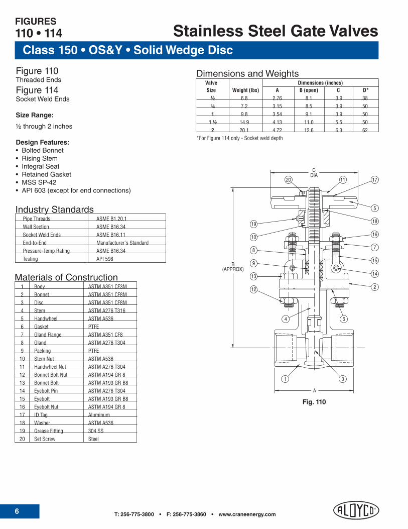
T: 256-775-3800 • F: 256-775-3860 • www.craneenergy.com6
Stainless Steel Gate Valves
Figure 110Threaded Ends
Figure 114Socket Weld Ends
Size Range:
½ through 2 inches
Design Features:• BoltedBonnet• RisingStem• IntegralSeat• RetainedGasket• MSSSP-42• API603(exceptforendconnections)
IndustryStandards Pipe Threads ASME B1.20.1 Wall Section ASME B16.34 Socket Weld Ends ASME B16.11 End-to-End Manufacturer's Standard Pressure-Temp Rating ASME B16.34 Testing API 598
Materials of Construction 1 Body ASTM A351 CF3M 2 Bonnet ASTM A351 CF8M 3 Disc ASTM A351 CF8M 4 Stem ASTM A276 T316 5 Handwheel ASTM A536 6 Gasket PTFE 7 Gland Flange ASTM A351 CF8 8 Gland ASTM A276 T304 9 Packing PTFE 10 Stem Nut ASTM A536 11 Handwheel Nut ASTM A276 T304 12 Bonnet Bolt Nut ASTM A194 GR 8 13 Bonnet Bolt ASTM A193 GR B8 14 Eyebolt Pin ASTM A276 T304 15 Eyebolt ASTM A193 GR B8 16 Eyebolt Nut ASTM A194 GR 8 17 ID Tag Aluminum 18 Washer ASTM A536 19 Grease Fitting 304 SS 20 Set Screw Steel
FIGURES110 • 114
Class 150 • OS&Y • Solid Wedge Disc
31
B
A
(APPROX)
DIAC
12
13
9
20 11
8
14
10
19
4 6
15
7
16
2
18
5
17
Fig. 110
Dimensions and Weights Valve Dimensions (inches) Size Weight (lbs) A B (open) C D* ½ 6.8 2.76 8.1 3.9 .38 ¾ 7.2 3.15 8.5 3.9 .50 1 9.8 3.54 9.1 3.9 .50 1 ½ 14.9 4.13 11.0 5.5 .50 2 20.1 4.72 12.6 6.3 .62*For Figure 114 only - Socket weld depth
T: 562-426-2531 • F: 562-490-9546 • www.craneenergy.com 7
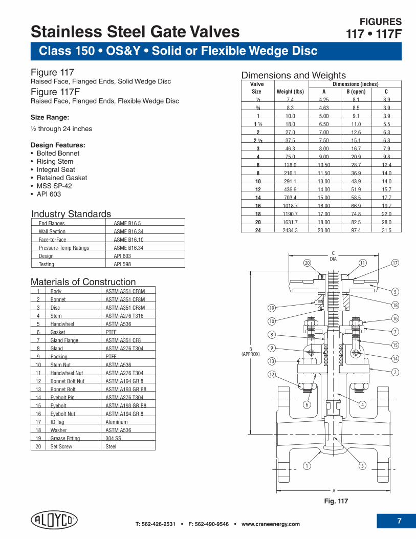
Class 150 • OS&Y • Solid or Flexible Wedge DiscStainless Steel Gate Valves
Figure 117Raised Face, Flanged Ends, Solid Wedge Disc
Figure 117FRaised Face, Flanged Ends, Flexible Wedge Disc
Size Range:
½ through 24 inches
Design Features:• BoltedBonnet• RisingStem• IntegralSeat• RetainedGasket• MSSSP-42• API603
IndustryStandards End Flanges ASME B16.5 Wall Section ASME B16.34 Face-to-Face ASME B16.10 Pressure-Temp Ratings ASME B16.34 Design API 603 Testing API 598
FIGURES117 • 117F
Materials of Construction 1 Body ASTM A351 CF8M 2 Bonnet ASTM A351 CF8M 3 Disc ASTM A351 CF8M 4 Stem ASTM A276 T316 5 Handwheel ASTM A536 6 Gasket PTFE 7 Gland Flange ASTM A351 CF8 8 Gland ASTM A276 T304 9 Packing PTFE 10 Stem Nut ASTM A536 11 Handwheel Nut ASTM A276 T304 12 Bonnet Bolt Nut ASTM A194 GR 8 13 Bonnet Bolt ASTM A193 GR B8 14 Eyebolt Pin ASTM A276 T304 15 Eyebolt ASTM A193 GR B8 16 Eyebolt Nut ASTM A194 GR 8 17 ID Tag Aluminum 18 Washer ASTM A536 19 Grease Fitting 304 SS 20 Set Screw Steel
31
B(APPROX)
DIAC
A
12
13
9
20 11
8
14
10
19
46
15
7
16
2
18
5
17
Fig. 117
Dimensions and Weights Valve Dimensions (inches) Size Weight (lbs) A B (open) C ½ 7.4 4.25 8.1 3.9 ¾ 8.3 4.63 8.5 3.9 1 10.0 5.00 9.1 3.9 1 ½ 18.0 6.50 11.0 5.5 2 27.0 7.00 12.6 6.3 2 ½ 37.5 7.50 15.1 6.3 3 46.3 8.00 16.7 7.9 4 75.0 9.00 20.9 9.8 6 128.0 10.50 28.7 12.4 8 216.1 11.50 36.9 14.0 10 291.1 13.00 43.9 14.0 12 436.6 14.00 51.9 15.7 14 703.4 15.00 58.5 17.7 16 1018.7 16.00 66.9 19.7 18 1190.7 17.00 74.8 22.0 20 1631.7 18.00 82.5 28.0 24 2434.3 20.00 97.4 31.5

T: 256-775-3800 • F: 256-775-3860 • www.craneenergy.com8
Class 300 • OS&Y • Solid Wedge DiscStainless Steel Gate Valves
Figure 2110Threaded Ends
Figure 2114Socket Weld Ends
Size Range:
½ through 2 inches
Design Features:• BoltedBonnet• RetainedGasket• RisingStem• IntegralSeat• MSSSP-42• ASMEB16.34
IndustryStandards Pipe Threads ASME B1.20.1 Wall Section ASME B16.34 Socket Weld Ends ASME B16.11 End-to-End Manufacturer's Standard Pressure-Temp. Rating ASME B16.34 Testing API 598
Materials of Construction 1 Body ASTM A351 CF3M 2 Bonnet ASTM A351 CF8M 3 Disc ASTM A351 CF8M 4 Stem ASTM A276 T316 5 Handwheel ASTM A536 6 Gasket PTFE 7 Gland Flange ASTM A351 CF8 8 Gland ASTM A276 T304 9 Packing PTFE 10 Stem Nut ASTM A536 11 Handwheel Nut ASTM A276 T304 12 Bonnet Bolt Nut ASTM A194 GR 8 13 Bonnet Bolt ASTM A193 GR B8 14 Eyebolt Pin ASTM A276 T304 15 Eyebolt ASTM A193 GR B8 16 Eyebolt Nut ASTM A194 GR 8 17 ID Tag Aluminum 18 Washer ASTM A536 19 Grease Fitting 304 SS 20 Set Screw Steel
FIGURES2110 • 2114
31
B
A
(APPROX)
DIAC
12
13
9
11 20
8
14
19
4
6
15
7
16
18
5
17
2
10
Fig. 2110
Dimensions and Weights Valve Dimensions (inches) Size Weight (lbs) A B (open) C D* ½ 6.8 3.23 8.1 3.9 .38 ¾ 7.0 3.23 8.1 3.9 .50 1 10.7 4.13 9.9 5.4 .50 1 ½ 19.5 4.92 12.0 7.9 .50 2 23.5 5.31 13.4 7.9 .62*For Figure 2114 only - Socket weld depth

T: 562-426-2531 • F: 562-490-9546 • www.craneenergy.com 9
Class 300 • OS&Y • Solid or Flexible Wedge DiscStainless Steel Gate Valves
Figure 2117Raised Face, Flanged Ends, Solid Wedge Disc
Figure 2117FRaised Face, Flanged Ends, Flexible Wedge Disc
Size Range:
½ through 24 inches
Design Features:• BoltedBonnet• RetainedGasket• RisingStem• IntegralSeat• MSSSP-42• ASMEB16.34
IndustryStandards End Flanges ASME B16.5 Wall Section ASME B16.34 Face-to-Face ASME B16.10 Pressure-Temp. Ratings ASME B16.34 Testing API 598
Dimensions and Weights Valve Dimensions (inches) Size Weight (lbs) A B (open) C ½ -- 5.50 8.1 3.9 ¾ -- 6.00 8.1 3.9 1 -- 6.50 9.9 5.4 1 ½ -- 7.50 12.0 7.9 2 -- 8.50 13.4 7.9 2 ½ 68.4 9.50 17.0 7.9 3 90.4 11.12 19.3 8.8 4 119.1 12.00 23.1 9.8 6 251.4 15.88 31.6 14.0 8 478.5 16.50 39.4 15.7 10 557.9 18.00 47.9 17.7 12 917.3 19.75 55.8 19.7 14 957.0 30.00 59.8 22.0 16 1206.1 33.00 66.7 24.8 18 1764.0 36.00 75.2 28.0 20 3281.0 39.00 83.4 31.5 24 4956.8 45.00 98.1 35.4
FIGURES2117 • 2117F
Materials of Construction 1 Body ASTM A351 CF8M 2 Bonnet ASTM A351 CF8M 3 Disc ASTM A351 CF8M 4 Stem ASTM A276 T316 5 Handwheel ASTM A536 6 Gasket PTFE 7 Gland Flange ASTM A351 CF8 8 Gland ASTM A276 T304 9 Packing PTFE 10 Stem Nut ASTM A536 11 Handwheel Nut ASTM A276 T304 12 Bonnet Bolt Nut ASTM A194 GR 8 13 Bonnet Bolt ASTM A193 GR B8 14 Eyebolt Pin ASTM A276 T304 15 Eyebolt ASTM A193 GR B8 16 Eyebolt Nut ASTM A194 GR 8 17 ID Tag Aluminum 18 Washer ASTM A536 19 Grease Fitting 304 SS 20 Set Screw Steel
31
B
A
(APPROX)
DIAC
12
13
9
11 20
8
14
19
4
6
15
7
16
18
5
17
2
10
Fig. 2117

T: 256-775-3800 • F: 256-775-3860 • www.craneenergy.com10
Class 600 • OS&Y • Solid Wedge DiscStainless Steel Gate Valves
Figure 4210Threaded Ends
Figure 4214Socket Weld Ends
Size Range:
½ through 2 inches
Design Features:• BoltedBonnet• RetainedGasket• RisingStem• IntegralSeat• ASMEB16.34
IndustryStandards Pipe Threads ASME B1.20.1 Wall Section ASME B16.34 Socket Weld Ends ASME B16.11 End-to-End Manufacturer's Standards Pressure-Temp Rating ASME B16.34 Testing API 598
FIGURES4210 • 4214
Materials of Construction 1 Body ASTM A351 CF3M 2 Bonnet ASTM A351 CF8M 3 Disc ASTM A351 CF8M 4 Stem ASTM A351 CF8M 5 Handwheel ASTM A536 6 Gasket PTFE 7 Gland Flange ASTM A351 CF8 8 Gland ASTM A276 T304 9 Packing PTFE 10 Stem Nut ASTM A536 11 Handwheel Nut ASTM A276 T304 12 Bonnet Bolt Nut ASTM A194 GR 8 13 Bonnet Bolt ASTM A193 GR B8 14 Eyebolt Pin ASTM A276 T304 15 Eyebolt ASTM A193 GR B8 16 Eyebolt Nut ASTM A194 GR 8 17 ID Tag Aluminum 18 Washer ASTM A536 19 Grease Fitting 304 SS 20 Set Screw Steel
31
B
A
(APPROX)
DIAC
12
13
9
11 20
8
14
19
4
6
15
7
16
18
5
17
2
10
Fig. 4210
Dimensions and Weights Valve Dimensions (inches) Size Weight (lbs) A B (open) C D* ½ 6.8 3.23 8.1 3.9 .38 ¾ 7.0 3.23 8.1 3.9 .50 1 10.7 4.13 9.9 5.4 .50 1 ½ 19.5 4.92 12.0 7.9 .50 2 23.5 5.31 13.4 7.9 .62*For Figure 4214 only - Socket weld depth

T: 562-426-2531 • F: 562-490-9546 • www.craneenergy.com 11
Class 600 • OS&Y • Flexible Wedge Disc
Stainless Steel Gate Valves
Figure 41172 to 12 inches, Raised Face, Flanged Ends
Size Range:
2 through 12 inches
Design Features:• BoltedBonnet• InsideScrew• RisingStem• IntegralSeat• TestedtoAPI598• ASMEB16.34
FIGURE4117
Fig. 4117
Dimensions and Weights Valve Dimensions (inches) Size Weight (lbs) A B (open) C 2 --- 11.50 13.4 7.9 2 ½ 111.8 13.00 18.0 8.8 3 145.9 14.00 20.1 9.8 4 277.1 17.00 25.0 14.0 6 534.8 22.00 37.7 17.7 8 938.4 26.00 42.4 19.7 10 1390.5 31.00 50.0 26.0 12 1993.4 33.00 63.0 27.5
IndustryStandards End Flanges ASME B16.5 Wall Section ASME B16.34 Face-to-Face ASME B16.10 Pressure-Temp. Ratings ASME B16.34 Testing API 598
Materials of Construction 1 Body ASTM A351 CF8M 2 Disc ASTM A351 CF8M + STL 3 Stem ASTM A182 F316 4 Body Nut ASTM A194 8M 5 Body Bolt ASTM A193 B8M 6 Ring Gasket ASTM A182 F316 7 Bonnet ASTM A351 CF8M 8 Packing Graphite 9 Gland Bolt ASTM A193 B8M 10 Gland ASTM A182 F316 11 Gland Flange ASTM A351 CF8M 12 Gland Nut ASTM A194 8M 13 Yoke ASTM A351 CF8M 14 Yoke Nut ASTM A439-D2 15 Handwheel Ductile Iron
A
B (APPROX)
C (DIA)

T: 256-775-3800 • F: 256-775-3860 • www.craneenergy.com12
Dimensions and Weights Valve Dimensions (inches) Size Weight (lbs) A B (open) C ½ 1.0 2.76 4.0 2.6 ¾ 1.4 3.15 4.0 2.6 1 1.8 3.54 4.2 3.0 1 ½ 3.3 4.72 5.4 3.4 2 4.9 5.51 5.8 4.0
200 CWP • Threaded Bonnet • Plug Type Disc
Stainless Steel Globe Valves
Figure 40Threaded Ends
Size Range:
½ through 2 inches
Design Features:• ThreadedBonnet•InsideScrew• RisingStem• IntegralSeat
Pressure Temperature Ratings:200 psi @ -20° to 100°F135 psi @ 500°F max.
IndustryStandards Threaded Ends ASME B1.20.1 End-to-End Manufacturer's Standard
FIGURE40
Materials of Construction 1 Body ASTM A351 CF8M 2 Bonnet ASTM A351 CF8M 3 Disc 316 SS 4 Stem 316 SS 5 Disc Nut 316 SS 6 Disc Washer 316 SS 7 Packing PTFE 8 Gland 316 SS 9 Gland Nut 316 SS 10 Packing Washer 316 SS 11 Gasket PTFE 12 Handwheel Ductile Iron 13 Handwheel Nut 304 SS 14 ID Tag 304 SS
B
A
(APPROX)
DIAC
5
11
2
10
6
1 3
8
7
9
4
14 13
12
Fig. 40

T: 562-426-2531 • F: 562-490-9546 • www.craneenergy.com 13
Class 150 • OS&Y • Plug Type Disc
Stainless Steel Globe Valves
Figure 310Threaded Ends
Figure 314Socket Weld Ends
Size Range:
½ through 2 inches
Design Features:• BoltedBonnet• RetainedGasket• RisingStem• IntegralSeat• MSSSP-42• ASMEB16.34
IndustryStandards Pipe Threads ASME B1.20.1 Wall Section ASME B16.34 Socket Weld Ends ASME B16.11 End-to-End Manufacturer's Standard Pressure-Temp. Ratings ASME B16.34 Testing API 598
FIGURES310 • 314
Materials of Construction 1 Body ASTM A351 CF3M 2 Bonnet ASTM A351 CF8M 3 Disc ASTM A351 CF8M 4 Stem ASTM A276 T316 5 Disc Nut ASTM A276 T316 6 Handwheel ASTM A536 7 Gasket PTFE 8 Gland Flange ASTM A351 CF8 9 Gland ASTM A276 T304 10 Packing PTFE 11 Stem Nut ASTM A536 12 Handwheel Nut ASTM A194 GR 8 13 Bonnet Bolt Nut ASTM A194 GR 8 14 Bonnet Bolt ASTM A193 GR B8 15 Eyebolt Pin ASTM A276 T304 16 Eyebolt ASTM A193 GR B8 17 Eyebolt Nut ASTM A194 GR 8 18 ID Tag Aluminum 19 Washer ASTM A276 T304
B
A
(APPROX)
DIAC
14
10
16
19 12
15
4 7
9
8
17
2
11
6
18
1 3
13
5
Fig. 310
Dimensions and Weights Valve Dimensions (inches) Size Weight (lbs) A B (open) C D* ½ 6.6 3.74 7.1 3.9 .38 ¾ 6.9 4.53 7.3 3.9 .50 1 8.7 4.92 7.9 3.9 .50 1 ½ 12.6 5.52 9.2 5.5 .50 2 17.3 6.50 10.2 6.3 .31* For Figure 314 only - socket weld depth

T: 256-775-3800 • F: 256-775-3860 • www.craneenergy.com14
Class 150 • OS&Y • Plug Type DiscStainless Steel Globe Valves
Figure 317Raised Face, Flanged Ends
Size Range:
½ through 12 inches
Design Features:• BoltedBonnet• RisingStem• RetainedGasket• IntegralSeat• DiscGuideBelowSeat• MSSSP-42• ASMEB16.34
IndustryStandards End Flanges ASME B16.5 Wall Section ASME B16.34 Face-to-Face ASME B16.10 Pressure-Temp. Ratings ASME B16.34 Testing API 598
FIGURE317
Materials of Construction 1 Body ASTM A351 CF8M 2 Bonnet ASTM A351 CF8M 3 Disc ASTM A351 CF8M 4 Stem ASTM A276 T316 5 Disc Nut ASTM A276 T316 6 Handwheel ASTM A536 7 Gasket PTFE 8 Gland Flange ASTM A351 CF8 9 Gland ASTM A276 T304 10 Packing PTFE 11 Stem Nut ASTM A536 12 Handwheel Nut ASTM A194 GR 8 13 Bonnet Bolt Nut ASTM A194 GR 8 14 Bonnet Bolt ASTM A193 GR B8 15 Eyebolt Pin ASTM A276 T304 16 Eyebolt ASTM A193 GR 8 17 Eyebolt Nut ASTM A194 GR 8 18 ID Tag Aluminum 19 Washer ASTM A276 T304
Dimensions and Weights Valve Dimensions (inches) Size Weight (lbs) A B (open) C ½ 7.6 4.25 7.1 3.9 ¾ 8.9 4.63 7.3 3.9 1 11.6 5.00 7.9 3.9 1 ½ 16.4 6.50 9.2 5.5 2 25.2 8.00 10.2 6.3 2 ½ 46.3 8.50 11.1 7.9 3 61.7 9.50 13.5 8.8 4 97.0 11.50 14.8 11.0 6 198.5 16.00 16.9 14.0 8 383.7 19.50 22.0 14.0 10 546.8 24.50 29.7 15.7 12 848.9 27.50 32.5 15.7
B
A
(APPROX)
DIAC
14
10
16
19 12
15
4 7
9
8
17
2
11
6
18
1 3
13
5
Fig. 317

T: 562-426-2531 • F: 562-490-9546 • www.craneenergy.com 15
Class 300 • OS&Y • Plug Type DiscStainless Steel Globe Valves
Figure 2310Threaded Ends
Figure 2314Socket Weld Ends
Size Range:
½ through 2 inches
Design Features:•BoltedBonnet• RisingStem•RetainedGasket• IntegralSeat• MSSSP-42
IndustryStandards Pipe Threads ASME B1.20.1 Wall Section ASME B16.34 Face-to-Face Manufacturer's Standard Pressure-Temp. Ratings ASME B16.34 Socket Weld Ends ASME B16.11 Testing API 598
FIGURES2310 • 2314
Materials of Construction 1 Body ASTM A351 CF3M 2 Bonnet ASTM A351 CF8M 3 Disc ASTM A351 CF8M 4 Stem ASTM A276 T316 5 Handwheel ASTM A536 6 Gasket PTFE 7 Gland Flange ASTM A351 CF8 8 Gland ASTM A276 T304 9 Packing PTFE 10 Stem Nut ASTM A536 11 Handwheel Nut ASTM A193 GR 8 12 Bonnet Bolt Nut ASTM A194 GR 8 13 Bonnet Bolt ASTM A193 GR B8 14 Eyebolt Pin ASTM A276 T304 15 Eyebolt ASTM A193 GR B8 16 Eyebolt Nut ASTM A194 GR 8 17 ID Tag Aluminum 18 Washer 304 SS 19 Stem Ring ASTM A276 T316
12
19
13
1 3
4
6
2
14
(APPROX)B
A
8
9
7
15
16
10
5
18DIAC
11 17
Fig. 2310
Dimensions and Weights Valve Dimensions (inches) Size Weight (lbs) A B (open) C D* ½ 7.0 3.23 7.8 3.9 .38 ¾ 7.0 3.23 7.8 3.9 .50 1 10.3 4.13 9.0 3.9 .50 1 ½ 18.2 4.92 10.7 5.5 .50 2 22.6 5.91 11.3 6.3 .62* For Figure 2314 only - socket weld depth

T: 256-775-3800 • F: 256-775-3860 • www.craneenergy.com16
Class 300 • OS&Y • Plug Type Disc
Stainless Steel Globe Valves
Figure 2317Raised Face, Flanged Ends
Size Range:
½ through 8 inches
Design Features:• BoltedBonnet• RetainedGasket• RisingStem,RisingHandwheel• IntegralSeat• MSSSP-42• ASMEB16.34
IndustryStandards End Flanges ASME B16.5 Wall Section ASME B16.34 Face-to-Face ASME B16.10 Pressure-Temp. Ratings ASME B16.34 Testing API 598
Dimensions and Weights Valve Dimensions (inches) Size Weight (lbs) A B (open) C ½ --- 6.00 7.8 3.9 ¾ --- 7.00 7.8 3.9 1 --- 8.00 9.0 3.9 1 ½ --- 9.00 10.7 5.5 2 --- 10.50 11.3 6.3 2 ½ 83.8 11.50 13.9 7.9 3 83.8 12.50 15.1 8.8 4 130.1 14.00 17.4 11.0 6 317.5 17.50 22.3 15.8 8 562.3 22.00 24.2 15.8
FIGURE2317
Materials of Construction 1 Body ASTM A351 CF8M 2 Bonnet ASTM A351 CF8M 3 Disc ASTM A351 CF8M 4 Stem ASTM A276 T316 5 Handwheel ASTM A536 6 Gasket PTFE 7 Gland Flange ASTM A351 CF8 8 Gland ASTM A276 T304 9 Packing PTFE 10 Stem Nut ASTM A536 11 Handwheel Nut ASTM A193 GR 8 12 Bonnet Bolt Nut ASTM A194 GR 8 13 Bonnet Bolt ASTM A193 GR B8 14 Eyebolt Pin ASTM A276 T304 15 Eyebolt ASTM A193 GR B8 16 Eyebolt Nut ASTM A194 GR 8 17 ID Tag Aluminum 18 Washer 304 SS 19 Stem Ring ASTM A276 T316
12
19
13
1 3
4
6
2
14
(APPROX)B
A
8
9
7
15
16
10
5
18DIAC
11 17
Fig. 2317

T: 562-426-2531 • F: 562-490-9546 • www.craneenergy.com 17
Class 600 • OS&Y • Plug Type DiscStainless Steel Globe Valves
Figure 4310Threaded Ends
Figure 4314Socket Weld Ends
Size Range:
½ through 2 inches
Design Features:•BoltedBonnet• RisingStem•RetainedGasket• IntegralSeat• MSSSP-42
IndustryStandards Pipe Threads ASME B1.20.1 Wall Section ASME B16.34 Face-to-Face Manufacturer's Standard Pressure-Temp. Ratings ASME B16.34 Socket Weld Ends ASME B16.11 Testing API 598
FIGURES4310 • 4314
Materials of Construction 1 Body ASTM A351 CF3M 2 Bonnet ASTM A351 CF8M 3 Disc ASTM A351 CF8M 4 Stem ASTM A276 T316 5 Handwheel ASTM A536 6 Gasket PTFE 7 Gland Flange ASTM A351 CF8 8 Gland ASTM A276 T304 9 Packing PTFE 10 Stem Nut ASTM A536 11 Handwheel Nut ASTM A193 GR 8 12 Bonnet Bolt Nut ASTM A194 GR 8 13 Bonnet Bolt ASTM A193 GR B8 14 Eyebolt Pin ASTM A276 T304 15 Eyebolt ASTM A193 GR B8 16 Eyebolt Nut ASTM A194 GR 8 17 ID Tag Aluminum 18 Washer 304 SS 19 Stem Ring ASTM A276 T316
12
19
13
1 3
4
6
2
14
(APPROX)B
A
8
9
7
15
16
10
5
18DIAC
11 17
Fig. 4310
Dimensions and Weights Valve Dimensions (inches) Size Weight (lbs) A B (open) C D* ½ 7.0 3.23 7.8 3.9 .38 ¾ 7.0 3.23 7.8 3.9 .50 1 10.3 4.13 9.0 3.9 .50 1 ½ 18.2 4.92 10.7 5.5 .50 2 22.6 5.91 11.3 6.3 .62* For Figure 2314 only - socket weld depth
T: 256-775-3800 • F: 256-775-3860 • www.craneenergy.com18
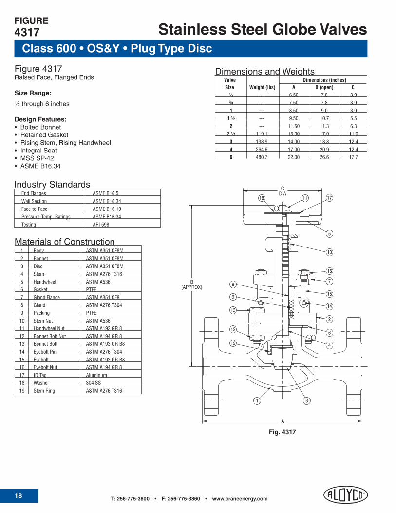
Class 600 • OS&Y • Plug Type Disc
Stainless Steel Globe Valves
Figure 4317Raised Face, Flanged Ends
Size Range:
½ through 6 inches
Design Features:• BoltedBonnet• RetainedGasket• RisingStem,RisingHandwheel• IntegralSeat• MSSSP-42• ASMEB16.34
IndustryStandards End Flanges ASME B16.5 Wall Section ASME B16.34 Face-to-Face ASME B16.10 Pressure-Temp. Ratings ASME B16.34 Testing API 598
Dimensions and Weights Valve Dimensions (inches) Size Weight (lbs) A B (open) C ½ --- 6.50 7.8 3.9 ¾ --- 7.50 7.8 3.9 1 --- 8.50 9.0 3.9 1 ½ --- 9.50 10.7 5.5 2 --- 11.50 11.3 6.3 2 ½ 119.1 13.00 17.0 11.0 3 138.9 14.00 18.8 12.4 4 264.6 17.00 20.9 12.4 6 480.7 22.00 26.6 17.7
FIGURE4317
Materials of Construction 1 Body ASTM A351 CF8M 2 Bonnet ASTM A351 CF8M 3 Disc ASTM A351 CF8M 4 Stem ASTM A276 T316 5 Handwheel ASTM A536 6 Gasket PTFE 7 Gland Flange ASTM A351 CF8 8 Gland ASTM A276 T304 9 Packing PTFE 10 Stem Nut ASTM A536 11 Handwheel Nut ASTM A193 GR 8 12 Bonnet Bolt Nut ASTM A194 GR 8 13 Bonnet Bolt ASTM A193 GR B8 14 Eyebolt Pin ASTM A276 T304 15 Eyebolt ASTM A193 GR B8 16 Eyebolt Nut ASTM A194 GR 8 17 ID Tag Aluminum 18 Washer 304 SS 19 Stem Ring ASTM A276 T316
12
19
13
1 3
4
6
2
14
(APPROX)B
A
8
9
7
15
16
10
5
18DIAC
11 17
Fig. 4317

T: 562-426-2531 • F: 562-490-9546 • www.craneenergy.com 19
200 CWP • Y-Pattern • Threaded Cap
Stainless Steel Check Valves
Figure 49Threaded Ends
Size Range:
½ through 2 inches
Design Features:• IntegralSeat• YPattern
Pressure Temperature Ratings:• 200psi@-20°Fto100°F• 135psi@500°FMax
IndustryStandards Pipe Threads ASME B1.20.1
Materials of Construction 1 Body ASTM A351 CF8M 2 Cap ASTM A351 CF8M 3 Disc ASTM A351 CF8M 4 Hinge Arm ASTM A351 CF8M 5 Hinge Pin 316 SS 6 Disc Nut 316 SS 7 Disc Washer 316 SS 8 Plug 316 SS 9 Seal PTFE 10 Gasket PTFE
Dimensions and Weights Valve Dimensions (inches) Size Weight (lbs) A B ½ 0.7 2.56 1.8 ¾ 1.1 3.15 2.0 1 1.5 3.54 2.4 1 ½ 3.1 4.72 3.2 2 4.6 5.51 3.7
FIGURE49
Fig. 49
1 8 9 4 5 3 10 6 7 2
B
A

T: 256-775-3800 • F: 256-775-3860 • www.craneenergy.com20
Class 150 • Bolted Cover
Stainless Steel Check Valves
Figure 370Threaded Ends
Figure 374Socket Weld Ends
Size Range:
½ through 2 inches
Design Features:• RetainedGasket• IntegralSeat• ASMEB16.34
IndustryStandards Pipe Threads ASME B2.1 Wall Section ASME B16.34 Socket Weld Ends ASME B16.11 End-to-End Manufacturer's Standard Pressure Temp. Ratings ASME B16.34 Testing API 598
Dimensions and Weights Valve Dimensions (inches) Size Weight (lbs) A B C* ½ 3.5 3.35 2.4 .38 ¾ 3.7 3.74 2.8 .50 1 5.5 4.53 3.1 .50 1 ½ 8.6 4.92 4.1 .50 2 10.3 5.91 4.6 .62* For Figure 374 only - socket weld depth
FIGURES370 • 374
Materials of Construction 1 Body ASTM A351 CF3M 2 Cover ASTM A351 CF8M 3 Disc ASTM A351 CF8M 4 Hinge Arm ASTM A351 CF8M 5 Hinge Pin ASTM A276 T316 6 Disc Washer ASTM A276 T304 7 Disc Nut ASTM A194 GR 8 8 Plug ASTM A276 T316 9 Gasket PTFE 10 Plug Seal PTFE 11 Cover Bolt ASTM A193 GR B8 12 Cover Bolt Nut ASTM A194 GR 8 13 ID Tag ASTM A276 T304
B
A
3 4 6 7 1
2
9131085 11
12
Fig. 370

T: 562-426-2531 • F: 562-490-9546 • www.craneenergy.com 21
Class 150 • Bolted CoverStainless Steel Check Valves
Figure 377Raised Face, Flanged Ends
Size Range:
½ through 24 inches
Design Features:• RetainedGasket• IntegralSeat• MSSSP-42• ASMEB16.34
IndustryStandards End Flanges ASME B16.5 Wall Section ASME B16.34 Face-to-Face ASME B16.10 Pressure-Temp. Ratings ASME B16.34 Testing API 598
Dimensions and Weights Valve Dimensions (inches) Size Weight (lbs) A B ½ 4.2 4.25 2.4 ¾ 5.6 4.63 2.8 1 8.4 5.00 3.1 1 ½ 13.5 6.50 4.1 2 20.4 8.00 4.6 2 ½ 50.7 8.50 6.1 3 57.3 9.50 6.3 4 99.2 11.50 7.9 6 172.0 14.00 9.8 8 299.9 19.50 11.5 10 471.9 24.50 13.0 12 707.8 27.50 13.9 14 904.1 31.00 15.5 16 1133.4 34.00 16.5 18 1633.9 38.50 20.1 20 2070.5 38.50 21.7 24 2967.9 51.00 22.0
FIGURE377
Materials of Construction 1 Body ASTM A351 CF8M 2 Cover ASTM A351 CF8M 3 Disc ASTM A351 CF8M 4 Hinge Arm ASTM A351 CF8M 5 Hinge Pin ASTM A276 T316 6 Disc Washer ASTM A276 T304 7 Disc Nut ASTM A194 GR 8M 8 Plug ASTM A276 T316 9 Gasket PTFE 10 Plug Seal PTFE 11 Cover Bolt ASTM A193 GR B8 12 Cover Bolt Nut ASTM A194 GR 8 13 ID Tag ASTM A276 T304
B
A
3 4 6 7 1
12
9131085 11
2
Fig. 377

T: 256-775-3800 • F: 256-775-3860 • www.craneenergy.com22
Class 300 • Bolted Cover
Stainless Steel Check Valves
Figure 2370Threaded Ends
Figure 2374Socket Weld Ends
Size Range:
½ through 2 inches
Design Features:•RetainedGasket• IntegralSeat
IndustryStandards Pipe Threads ASME B1.20.1 Wall Section ASME B16.34 Socket Weld Ends ASME B16.11 End-to-End Manufacturer's Standard Pressure Temp. Ratings ASME B16.34 Testing API 598
Materials of Construction 1 Body ASTM A351 CF3M 2 Cover ASTM A351 CF8M 3 Disc ASTM A351 CF8M 4 Hinge Arm ASTM A351 CF8M 5 Hinge Pin ASTM A276 T316 6 Disc Washer ASTM A276 T304 7 Disc Nut ASTM A194 GR 8 8 Gasket PTFE 9 Cover Bolt ASTM A193 GR B8 10 Cover Bolt Nut ASTM A194 GR 8 11 ID Tag ASTM A276 T304
Dimensions and Weights Valve Dimensions (inches) Size Weight (lbs) A B C* ½ 4.2 3.23 3.3 .38 ¾ 4.2 3.23 3.3 .50 1 5.8 4.13 3.4 .50 1 ½ 10.1 4.92 3.9 .50 2 13.1 5.31 4.1 .62* For Figure 2374 only - socket weld depth
FIGURES2370 • 2374
B
A
3 6 7 1
2
811
5
9
104
Fig. 2370
T: 562-426-2531 • F: 562-490-9546 • www.craneenergy.com 23
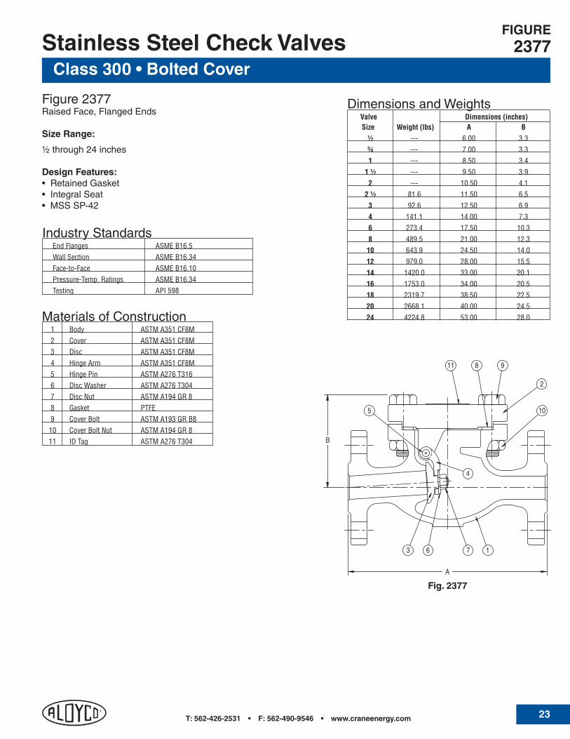
Class 300 • Bolted CoverStainless Steel Check Valves
Figure 2377Raised Face, Flanged Ends
Size Range:
½ through 24 inches
Design Features:• RetainedGasket• IntegralSeat• MSSSP-42
IndustryStandards End Flanges ASME B16.5 Wall Section ASME B16.34 Face-to-Face ASME B16.10 Pressure-Temp. Ratings ASME B16.34 Testing API 598
Dimensions and Weights Valve Dimensions (inches) Size Weight (lbs) A B ½ --- 6.00 3.3 ¾ --- 7.00 3.3 1 --- 8.50 3.4 1 ½ --- 9.50 3.9 2 --- 10.50 4.1 2 ½ 81.6 11.50 6.5 3 92.6 12.50 6.9 4 141.1 14.00 7.3 6 273.4 17.50 10.3 8 489.5 21.00 12.3 10 643.9 24.50 14.0 12 979.0 28.00 15.5 14 1420.0 33.00 20.1 16 1753.0 34.00 20.5 18 2319.7 38.50 22.5 20 2668.1 40.00 24.5 24 4224.8 53.00 28.0Materials of Construction
1 Body ASTM A351 CF8M 2 Cover ASTM A351 CF8M 3 Disc ASTM A351 CF8M 4 Hinge Arm ASTM A351 CF8M 5 Hinge Pin ASTM A276 T316 6 Disc Washer ASTM A276 T304 7 Disc Nut ASTM A194 GR 8 8 Gasket PTFE 9 Cover Bolt ASTM A193 GR B8 10 Cover Bolt Nut ASTM A194 GR 8 11 ID Tag ASTM A276 T304
FIGURE2377
B
A
3 6 7 1
10
811 9
4
2
5
Fig. 2377

T: 256-775-3800 • F: 256-775-3860 • www.craneenergy.com24
Class 600 • Bolted Cover
Stainless Steel Check Valves
Figure 4370Threaded Ends
Figure 4374Socket Weld Ends
Size Range:
½ through 2 inches
Design Features:•RetainedGasket• IntegralSeat
IndustryStandards Pipe Threads ASME B1.20.1 Wall Section ASME B16.34 Socket Weld Ends ASME B16.11 End-to-End Manufacturer's Standard Pressure Temp. Ratings ASME B16.34 Testing API 598
Materials of Construction 1 Body ASTM A351 CF3M 2 Cover ASTM A351 CF8M 3 Disc ASTM A351 CF8M 4 Hinge Arm ASTM A351 CF8M 5 Hinge Pin ASTM A276 T316 6 Disc Washer ASTM A276 T304 7 Disc Nut ASTM A194 GR 8 8 Gasket PTFE 9 Cover Bolt ASTM A193 GR B8 10 Cover Bolt Nut ASTM A194 GR 8 11 ID Tag ASTM A276 T304
Dimensions and Weights Valve Dimensions (inches) Size Weight (lbs) A B C* ½ 4.2 3.23 3.3 .38 ¾ 4.2 3.23 3.3 .50 1 5.8 4.13 3.4 .50 1 ½ 10.1 4.92 3.9 .50 2 13.1 5.31 4.1 .62* For Figure 4374 only - socket weld depth
FIGURES4370 • 4374
B
A
3 6 7 1
2
811
5
9
104
Fig. 4370

T: 562-426-2531 • F: 562-490-9546 • www.craneenergy.com 25
Class 600 • Bolted CoverStainless Steel Check Valves
Figure 4377Raised Face, Flanged Ends
Size Range:
½ through 12 inches
Design Features:• RetainedGasket• IntegralSeat• MSSSP-42
IndustryStandards End Flanges ASME B16.5 Wall Section ASME B16.34 Face-to-Face ASME B16.10 Pressure-Temp. Ratings ASME B16.34 Testing API 598
Dimensions and Weights Valve Dimensions (inches) Size Weight (lbs) A B ½ --- 6.50 3.3 ¾ --- 7.50 3.3 1 --- 8.50 3.4 1 ½ --- 9.50 3.9 2 --- 11.50 4.1 2 ½ 108.0 13.00 7.9 3 123.5 14.00 8.3 4 227.1 17.00 10.1 6 449.8 22.00 13.0 8 754.1 26.00 14.3 10 1375.9 31.00 18.3 12 1711.1 33.00 19.1
Materials of Construction 1 Body ASTM A351 CF8M 2 Cover ASTM A351 CF8M 3 Disc ASTM A351 CF8M 4 Hinge Arm ASTM A351 CF8M 5 Hinge Pin ASTM A276 T316 6 Disc Washer ASTM A276 T304 7 Disc Nut ASTM A194 GR 8 8 Gasket PTFE 9 Cover Bolt ASTM A193 GR B8 10 Cover Bolt Nut ASTM A194 GR 8 11 ID Tag ASTM A276 T304
FIGURE4377
B
A
3 6 7 1
10
811 9
4
2
5
Fig. 4377

T: 256-775-3800 • F: 256-775-3860 • www.craneenergy.com26
Stainless Steel Ball Valves
Figure 9431-S-LLThreaded Ends
Size Range:¼ through 2 inches
Design Features:• MSSSP-110• FullPort• LockingHandle• StandardMountingPad• FiresafetoAPI607
Materials of Construction 1 Body CF8M 2 End Cap CF8M 3 Solid Ball CF8M 4 Ball Seats 15% R-PTFE 5 Body Seats PTFE 6 Stem AISI 304 7 Thrust Washer 25% GF +PTFE 8 Stem Packing PTFE 9 Gland Nut AISI 304 10 Handle AISI 304 11 Spring Washer AISI 304 12 Stem Nut AISI 304 13 Plastic Plastic 14 Locking Device AISI 304
2000 CWP • Two-Piece Body
FIGURE9431-S-LL
Fig. 9431-S-LL
Dimensions and Weights Dimensions (inches) Weight (lbs) d H L W S S1 X N P BL ¼ 0.7 0.5 2.1 2.4 4.1 0.6 0.4 0.2 0.5 1.1
5/16
³⁄8 0.7 0.5 2.1 2.4 4.1 0.6 0.4 0.2 0.5 1.1 5/16
½ 0.7 0.6 2.1 2.4 3.7 0.6 0.4 0.2 0.5 1.1 5/16
¾ 1.3 0.75 2.4 3.0 4.3 0.8 0.5 0.3 0.8 1.4 3/8
1 2.2 1.00 2.9 3.5 5.3 0.9 0.6 0.3 0.9 1.4 7/16
1 ¼ 3.5 1.25 3.1 3.9 5.3 0.9 0.6 0.3 0.9 1.5 7/16
1 ½ 5.0 1.50 3.6 4.6 6.5 1.0 0.7 0.4 0.9 1.5 ½ 2 8.2 2.00 4.0 5.4 6.5 1.0 0.7 0.4 1.3 1.5 ½
ValveSize

T: 562-426-2531 • F: 562-490-9546 • www.craneenergy.com 27
Materials of Construction
Composition, % ASTM A351 ASTM A494 Element CF8M CF3M CN7M M-35-1 CW-12MW Carbon 0.08 0.03 0.07 0.35 0.12 Chromium 18.0 - 21.0 17.0 - 21.0 19.0 - 22.0 0.00 15.5 - 17.5 Columbium (Niobium) 0.00 0.00 0.00 0.50 0.00 Copper 0.00 0.00 3.0 - 4.0 26.0 - 33.0 0.00 Iron 0.00 0.00 0.00 3.50 4.5 - 7.5 Manganese 1.50 1.50 1.50 1.50 1.00 Molybdenum 2.0 - 3.0 2.0 - 3.0 2.0 - 3.0 0.00 16.0 - 18.0 Nickel 9.0 - 12.0 9.0 - 13.0 27.5 - 30.5 balance balance Phosphorus 0.04 0.04 0.04 0.03 0.04 Silicon 1.50 1.50 1.50 1.25 1.00 Sulfur 0.04 0.04 0.04 0.03 0.03 Tungsten 0.00 0.00 0.00 0.00 3.75 - 5.25 Vanadium 0.00 0.00 0.00 0.00 0.20 - 0.40Assume all values are maximum, unless a range is given Tensile Requirements Mechanical Properties Tensile Strength 70,000 70,000 62,000 65,000 72,000 Yield Strength 30,000 30,000 25,000 25,000 40,000 Elongation in 2 inches, % 30.0% 30.0% 35.0% 25.0% 4.0%
T: 256-775-3800 • F: 256-775-3860 • www.craneenergy.com28
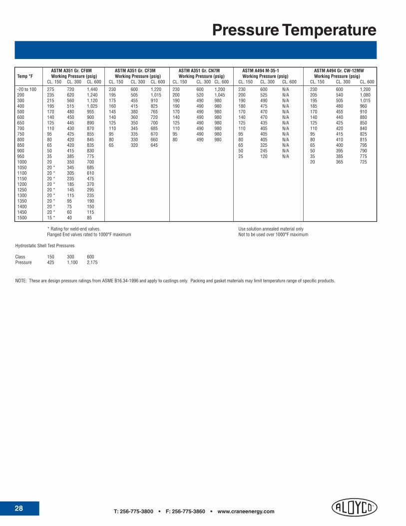
Pressure Temperature
ASTM A351 Gr. CF8M ASTM A351 Gr. CF3M ASTM A351 Gr. CN7M ASTM A494 M-35-1 ASTM A494 Gr. CW-12MWTemp °F Working Pressure (psig) Working Pressure (psig) Working Pressure (psig) Working Pressure (psig) Working Pressure (psig) CL. 150 CL. 300 CL. 600 CL. 150 CL. 300 CL. 600 CL. 150 CL. 300 CL. 600 CL. 150 CL. 300 CL. 600 CL. 150 CL. 300 CL. 600
-20 to 100 275 720 1,440 230 600 1,220 230 600 1,200 230 600 N/A 230 600 1,200200 235 620 1,240 195 505 1,015 200 520 1,045 200 525 N/A 205 540 1,080300 215 560 1,120 175 455 910 190 490 980 190 490 N/A 195 505 1,015400 195 515 1,025 160 415 825 190 490 980 180 475 N/A 185 480 960500 170 480 955 145 380 765 170 490 980 170 470 N/A 170 455 910600 140 450 900 140 360 720 140 490 980 140 470 N/A 140 440 880650 125 445 890 125 350 700 125 490 980 125 435 N/A 125 425 850700 110 430 870 110 345 685 110 490 980 110 405 N/A 110 420 840750 95 425 855 95 335 670 95 490 980 95 405 N/A 95 415 825800 80 420 845 80 330 660 80 490 980 80 405 N/A 80 410 815850 65 420 835 65 320 645 65 325 N/A 65 400 795900 50 415 830 50 245 N/A 50 395 790950 35 385 775 25 120 N/A 35 385 7751000 20 350 700 20 365 7251050 20 * 345 685 1100 20 * 305 610 1150 20 * 235 475 1200 20 * 185 370 1250 20 * 145 295 1300 20 * 115 235 1350 20 * 95 190 1400 20 * 75 150 1450 20 * 60 115 1500 15 * 40 85
* Rating for weld-end valves. Use solution annealed material only Flanged End valves rated to 1000°F maximum Not to be used over 1000°F maximum Hydrostatic Shell Test Pressures
Class 150 300 600Pressure 425 1,100 2,175
NOTE: These are design pressure ratings from ASME B16.34-1996 and apply to castings only. Packing and gasket materials may limit temperature range of specific products.

T: 562-426-2531 • F: 562-490-9546 • www.craneenergy.com 29
Stainless Steel ValvesValve Marking System
ALOYCO
CCC
AAAA
FRONT BACK
GGGGGG
DDD
EEEEEEEEEEE
AAAA FF GGGGGG
FFBBB
Itisimportanttoproperlyidentifyvalvesinservicetoallowfortheorderingofreplacementpartsortoaddressquestionsorconcerns relating to Aloyco products. The valve marking system shown here will help customers identify valves accurately, speeding responses to customer service issues.
Valve Marking System Codes
AAAA Material (CF3M, CF8M, etc.)
BBB Size (½", 4", etc.)
CCC Class (150, 300, 600)
DDD ManufacturerIDNumber
EEEEEEEEEE Serial Number
FF Foundry Number
GGGGGG HeatNumber
Gate Valve

T: 256-775-3800 • F: 256-775-3860 • www.craneenergy.com30
Stainless Steel ValvesValve Marking System
ALOYCO
CCC
AAAA
FRONT BACK
GGGGGG
DDD
EEEEEEEEEEE
AAAA FF GGGGGG
FFBBB
ALOYCO
CCC
AAAA
FRONT BACK
GGGGGG
DDD
EEEEEEEEEEE
AAAA FF GGGGGG
FFBBB
Globe Valve
Check Valve


Global Headquarters19241 David Memorial Drive, Suite 150
Shenandoah, Texas 77385 Tel: 936-271-6500Fax: 936-271-6510
CV-203 1208 A Crane Co. Company
CEnTER LInE®
ResilientSeatedButterflyandCheckValvesPneumatic and Electric Actuators
Crane Energy Flow Solutionswww.craneenergy.com
Cullman, AL Operations2129 3rd Avenue S.E.
Cullman, Alabama 35055 Tel: 256-775-3800Fax: 256-775-3860
CRAnE®
CastSteel,Bronze,andIronValves
Customer Service2129 3rd Avenue S.E.
Cullman, Alabama 35055 Tel: 256-775-3800Fax: 256-775-3860
Crane, Center Line, Flowseal, Duo-Chek, Uni-Chek, Pacific, Jenkins, Aloyco, Noz-Chek, Compac-Noz and Wedgeplug are
all trademarks of Crane Co. ©2008
FLOWSEAL®
HighPerformanceButterflyValves
DUO-CHEk®
HighPerformanceWaferCheckValves
UnI-CHEk®
Severe Service Check Valves
PACIFIC®
HighPressureandSevereServiceValvesQuarter Turn Severe Service Plug Valves
JEnkInS®
Bronze,Iron,andCastSteelValves
ALOYCO®
CorrosionResistantGate,GlobeandCheckValves
nOz-CHEk® & COMPAC-nOz®
Severe Service, Nozzle-Type Check Valves
WEDGEPLUG®
Severe Service, Metal-Seated Plug Valves