Embed Size (px)
Citation preview

Almesaeed, R. N. F., Mellios, E., Doufexi, A., Nix, A. R., & Ameen, A.(2017). 3D Channel Models: Principles, Characteristics, and SystemImplications. IEEE Communications Magazine, 55(4), 152-159. DOI:10.1109/MCOM.2017.1500505
Peer reviewed version
Link to published version (if available):10.1109/MCOM.2017.1500505
Link to publication record in Explore Bristol ResearchPDF-document
This is the author accepted manuscript (AAM). The final published version (version of record) is available onlinevia IEEE at http://ieeexplore.ieee.org/abstract/document/7901494 . Please refer to any applicable terms of useof the publisher.
University of Bristol - Explore Bristol ResearchGeneral rights
This document is made available in accordance with publisher policies. Please cite only the publishedversion using the reference above. Full terms of use are available:http://www.bristol.ac.uk/pure/about/ebr-terms

This article presents a comprehensive review of the principles and characteristics of three-dimensional (3D) channel models. We
propose a framework for a 3D channel extension of the widely used two-dimensional (2D) 3GPP/ITU generic channel model. We
describe the main components and challenges of the newly proposed 3D channel model and the motivations that lie behind them. 3D
channel models specify multipath elevation angles as well as azimuth (or horizontal plane) angles. This enables the evaluation of 3D
MIMO techniques such as Full Dimension (FD) MIMO and per user 3D beamforming. We also provide a state-of-the-art review on
the evolution of channel models. The article ends with a discussion on the impact of 3D channel modelling on system level
performance.
Introduction
Most of the directional models in the literature, including the standardized ones, concentrate on the direction data in the azimuth
only plane. However, many measurement campaigns have demonstrated that elevation angles have a significant impact on
communication system level performance [1]. The development of a 3D channel model opened up possibilities for a variety of
strategies including FD-MIMO, user specific elevation beamforming and cell splitting by benefitting from the richness of the real
wireless channel [2]. In conventional MIMO systems, the antenna elements are deployed linearly in the azimuth plane only. However,
when the linear antenna elements are extended to the 2D plane, the elevation angle should also be considered to obtain accurate
correlation measure of the MIMO system. This requires both the azimuth and elevation angles to be represented in the propagation
model.
More analysis is required in terms of modelling the elevation related statistics such as the elevation spread & distribution, and
the power elevation spectrum. Research into the elevation angle domain can be tracked back to 1970 by T.Aulin, who extended
Clark’s scattering model to the 3D domain [3]. In this work, the author assumed a rectangular and truncated cosine function for the
elevation PAS for the elevation angles. Elevation studies fall into two categories: (i) modelling of elevation statistics at the UE. (ii)
Modelling of elevation at the BS, however, most of the studies in the literature have focused on elevation spectra at the UE, as they
have greater spread compared to the BS. UE measurements showed that MPCs arrived at the UE via over-the-rooftop propagation
tend to have higher elevation angle spreads compared to the MPCs that wave-guided in street canyons [4]. Extensive measurements
have been carried out in [5], which showed that a double exponential function is a good approximation for the elevation power
spectrum measured at the UE, with elevation spreads typically in range 10o-15o. At the BS, elevation spread is considerably smaller
according to [6]. In these studies the authors concluded that over-the-rooftop propagation and wave guiding in street provides different
contributions to the elevation spectrum, where clustering was also observed. In addition, measurement campaigns were carried out
such as in [7] to investigate the 3D characteristics of the wireless channel and to proposing elevation statistics of mainly urban
environments in macro and micro cells. These studies assumed different antenna configurations, and also different propagation
conditions such as indoor-to-outdoor propagation. Furthermore a high resolution 3D model of the direction of arrival of the MPCs in
an urban environment was proposed in [1] and the elevation dependence of the impinging power was investigated. Further analysis
of the impact of the 3D component on the antenna correlation and gain imbalance in MIMO systems was presented in [8].
The motivation behind 3D channel modelling encouraged standardized bodies such as 3GPP to work on defining future mobile
communication standards that provide accurate 3D channel models and help in evaluating the potential of advanced MIMO techniques
[9]. Topics of particular interest are the dependence of the mean elevation and elevation spread as a function of distance, the impact
of BS height on elevation spread and the best modelling of elevation statistical distributions. For example, the WINNER+ model has
3D Channel Models: Principles, Characteristics & System Implications Reham Nemer Almesaeed, Evangelos Mellios, Angela Doufexi and Andrew Nix .,University of Bristol
Araz Sabir Ameen., University of Sulaimani

reported results in terms of the angle spread (AS) at both the UE and BS in an attempt to extend from 2D into 3D model [10]. From
January 2013, the 3GPP working group 1 (WG1) has launched discussions on a 3D channel model, and since then many proposals
have been reported considering different propagation environments [11]. The 3GPP 3D channel model provides more flexibility for
the elevation dimension, this allows better modelling of the two dimensional antenna system. The contribution of this article is to
highlight the importance of elevation angle modelling and its impact on system level performance. It also review the authors proposed
model in this context, which is based on extensive ray tracing measurements to give more accurate modelling of the 3D channel
compared to the models based on measurements campaigns. The latter is limited by the number of measurements and the deployed
antenna type. Unlike the WINNER+ model, which assumes fixed elevation angle spread per environment, the article shows the
distance dependence of elevation spread. The authors model of elevation spread is considered and partially implemented in the 3GPP
3D channel model [11], and the proposed model is shown to match well with the smaller number of measurement observation available
at the time.
This article is organized as follows. We first present the characteristics and principles of 3D models and discuss the modeling
challenges associated with 3D multipath. Next we discuss the changes required to the existing 3GPP/ITU 2D channel model to develop
3D channels realizations suitable for system level studies. The impact of 3D multipath on system performance is addressed in the
final section.
Characteristics of elevation angle
Analysis of elevation spread
3D channel models have been developed in several high-profile projects such as WINNER+ [10]. However, most of these models
depend mainly on literature surveys rather than real-world measurements or ray tracing predictions. The WINNER’s model for the
elevation spread follows the azimuth plane, where fixed elevation spread is assumed per environment. For example, in urban-macro
environments the average elevation spread is 3o despite the UE is location from the Base Station (BS). However based on deterministic
predictions from our validated 3D ray tracing engine [12], we have observed that the mean elevation angle spread decreases as function
of distance from the BS.
Figure 1.Intuitive Explanation of Distance dependent elevation angle spread.
The tracer engine provides information on the power, phase, propagation time, angle-of-arrival and angle-of-departure in both
elevation and azimuth of each of the multipath components linking the BS to the UE. Ray geometries are computed using site-specific

geographic databases for terrain, buildings and foliage. Figure 1 presents an intuitive explanation of the distance dependency of the
elevation spread. Figure 1 considers a simple geometric model for the elevation dimension. As shown in the figure, as the UE
separation distance increases from the BS, the elevation angle spread decreases at the UE. The same trends were observed in the ray
tracing data. Figure 2 shows the range of predicted angular spreads for different UE locations from the BS generated from the ray
tracer predictions in central Bristol, UK. Figure 2(a) and Figure 2(b) show the mean and variance of the log of the elevation spread at
the UE as a function of separation distance from the BS. The mean elevation spread can be seen to decrease as a function of one-over-
distance for this urban-macro environment in non-line-of-sight conditions. According to Figure 2, we also observe that the range of
elevation angular spreads depends on the heights of the BS and UE. A comparison of the complementary distribution function of the
elevation arrival and departure angular spread is shown in Figures 2(c) and Figure 2(d) for large number of UEs distributed in the
distance range of 50-1000 m from BS. It is clearly shown that as the BS height increases, the range of angular spreads increase in the
elevation plane. Please note that, the term H10 in the figure refers to the BS height of 10 m, etc.
Figure 2. Analysis of predicted elevation angular spread.
Open issues in elevation domain modeling
The introduction of 3D channel modeling requires current 2D models to extend their propagation statistics to address the elevation
domain. This sub-section discusses some of the issues encountered when extending a 2D geometric based stochastic channel model
to consider multipath in the elevation and azimuth domains.
Azimuth & elevation angular dependence: Since the elevation and azimuth angles of electromagnetic waves depend on the
position of scatters and reflectors in 3D space, the modeling of elevation angular information should be correlated with the
azimuth plane. This is not taken into consideration in standardized channel models such as WINNER+, which proposes a set of
elevation statistics (e.g. spread, Power Angular Spread (PAS))that are independent of the azimuth statistics.
Elevation angular spread & spatial correlation: The Power Elevation Spectrum (PES) is another important statistical property
of the wireless channel and plays an important role in determining the spatial correlation present in MIMO systems. Most of the
current models (for example the WINNER+ model) use the lognormal distribution to fit the azimuth angular spread (AS) for
both BS and UE. Enhanced mathematical models can be explored to better fit the elevation statistics.
Antenna Radiation & Cross Polar Discrimination (XPD): The incorporation of elevation angles in the generation of the
channel response requires complete 3D antenna patterns. In the case of a polarized MIMO system, the XPD ratio plays an
important factor in determining the dependence of the antenna patterns at different polarizations. This factor depends on the
angular information and delay spread [13]. An enhanced XPD model is needed that takes into consideration the elevation
departure and arrival angles.

Modifications to channel generation
A framework for the generation of the 3D fading channel can be developed based on well-known 2D channel models, i.e., the
IMT-Advanced channel model defined by the ITU-R M.2135. This section will highlight the required modifications to perform this
3D extension [14].
General Framework
As shown in Figure 3, the channel generation process for the ITU-R GSCM [14] can be described using six steps. These are
classified into three phases: 1) UE parameters, 2) generation of LSP propagation parameter and 3) generation of channel impulse
response. The yellow highlighted fields represent the parts that require modification when performing the 3D extension. The user
parameter part (step1) is used to setup simulation parameters, such as the type of environment, the numbers of BSs and UEs, the
directions and speeds of the UE, and the propagation condition (LOS/NLOS). In this phase, the users also can supply the antenna at
both the BS and UE, the spacing and orientations of the elements. In this case and in order to fully utilize the 3D model, the imported
antenna patterns should be 3D providing information about the gain and polarization in both the azimuth and elevation planes.
The second part of the ITU-R GSCM creation process is the propagation parameter generation, which consists of Path Loss (PL),
Shadow fading (SF) calculation and the generation of the Large Scale Parameters (LSPs) and Small Scale Parameters (SSPs) for the
channel. The PL is calculated based on specified propagation condition provided in in step 2. The generation of the LSPs includes the
generation of different channel parameters based on a pre-defined PDF with specific mean and standard deviation. These include the
RMS Delay Spread (DS), the RMS Angel of Arrival (AOA) & Angle of Departure (AOD) in both azimuth and elevation, the K-
Factor and the SF. The de-correlation distances and cross correlations are calculated for the generated LSPs. For more details on these
parameters please refer to [14].
Figure 3. 3D Generic Channel Generation Process
The small-scale parameters are now generated based on the LSPs from step 3. The SSPs represent the information associated
with each MPC. This include the phase, delay, angular information for each individual cluster and ray within the cluster. This is
performed based on the predefined PDFs. In the proposed 3D extension to the ITU generic channel model, the elevation plane is
added in the modelling of the rays angles. Step 5 represents the generation of the channel impulse response in time domain. This
includes generating random phases for the rays within cluster, and apply the cross-polarization effect between antenna elements. Then
the Doppler effect is added in case of mobility.
Finally, in step 6, path-loss and shadow fading (SF) values are applied to the channel impulse responses. This stage enables
system level studies to be performed.
Review of proposed 3D channel models
Having described the principles of 3D channel modelling in the previous sections, we now present a review of our proposed 3D
channel model. The authors contributed by modifying the existing 2D ITU generic channel model [14] to include the proposed
elevation angle statistics. Channel statistics for many LSPs are generated from a validated ray tracer engine predictions [12]. An ideal
isotropic antenna patterns are applied during channel predictions stage to decouple the antenna system from the channel model. At
later stage in the system level study, any BS/UE antenna patterns can be applied as spatial-phase-polarization convolution process.
The proposed channel statistics provide modelling of the PL, SF, and angular spread in both azimuth and elevation planes. The model
covers also the de-correlation distances and the cross-correlation for the LSPs. The objective is to calculate the mean (µ) and standard
deviation (σ) of the log of all the LSPs based on the distribution functions assumed in the current 2D ITU channel model. An open
source code of the enhanced channel model is published in http://enhanced-3d-itu-channel-model.sourceforge.net . Readers are
referred to [15] for detailed discussion of the LSPs modelling process and the 3D tracer related configurations. The proposed channel
models are for macro and micro cell environments for different carrier frequencies such as 800 MHz, 2.4 GHz and 5.9 GHz, and for
both line-of-sight and non-line-of sight propagation conditions. It’s worth mentioning that the proposed statistics were obtained by
averaging all the channel predictions for London and Bristol cities, United Kingdom.
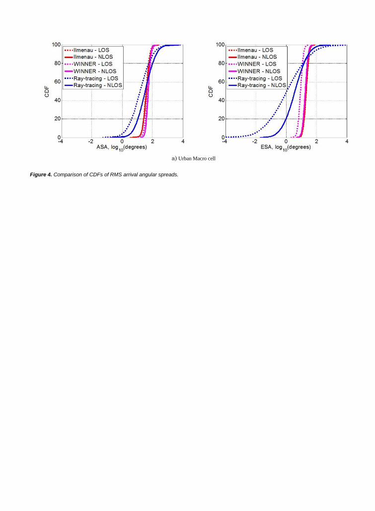
a) Urban Macro cell
b) Urban Pico cell
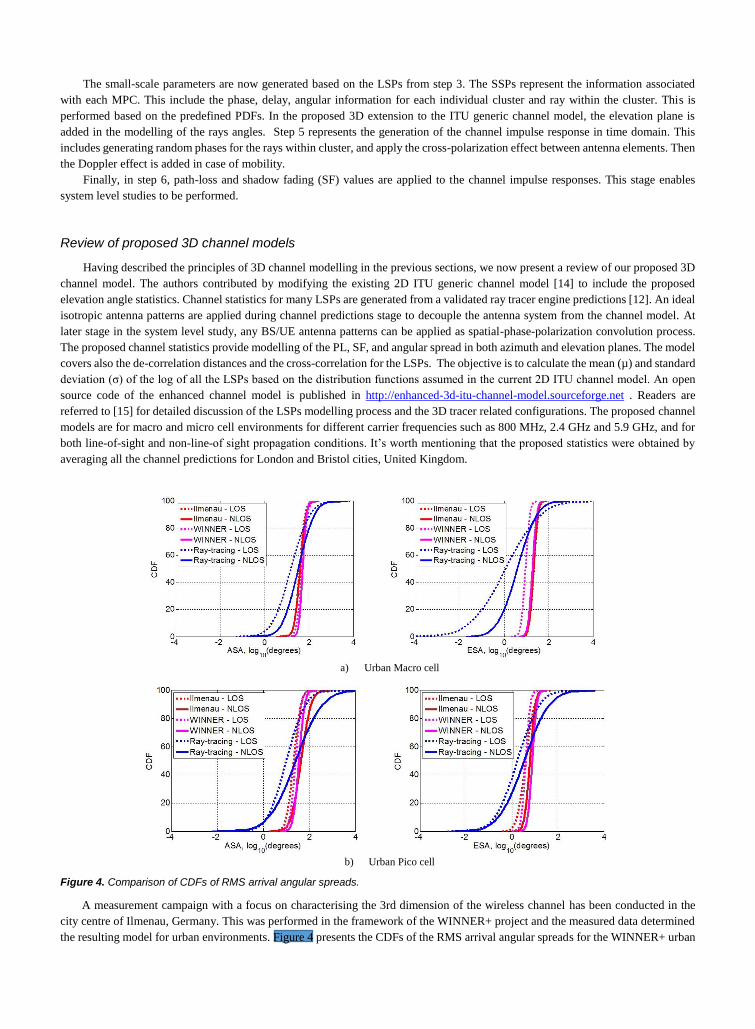
Figure 4. Comparison of CDFs of RMS arrival angular spreads.
A measurement campaign with a focus on characterising the 3rd dimension of the wireless channel has been conducted in the
city centre of Ilmenau, Germany. This was performed in the framework of the WINNER+ project and the measured data determined
the resulting model for urban environments. Figure 4 presents the CDFs of the RMS arrival angular spreads for the WINNER+ urban

channel model, the Ilmenau measurements and our ray-tracing based channel model. The latter shows the data for macro-cells at 2.6
GHz and for lamppost-mounted pico-cell BSs in Bristol. As expected, the Ilmenau measurements match well to the WINNER+ model,
but clear differences can be noticed with the ray-tracing results for Bristol. This highlights a disadvantage of an “one-size-fits-all”
empirical channel modelling approach. A possible reason for these differences in the elevation angle statistics are the different city
layouts and propagation environments (e.g. the city of Bristol is much more hilly and densely built than Ilmenau), details of the ray-
tracing database (e.g. the ray-tracer does not consider parked cars) and the limited number of measured links. In addition, the ray-
tracing predictions are based on isotropic antenna patterns, therefore no filtering of the MPCs is done at the UE side, which leads to
higher angular spread compared to the WINNER+ model and the Ilmenau measurements. For the latter, particular antennas were used
during the measurements [10], the radiation patterns of which resulted in inevitable spatial filtering of the MPCs. Finally, it should
be noted that the distance dependency of the elevation angle spread noted in the ray-tracing data is consistent with the 3GPP
observations in [11].
Impact on system level performance
In this section, the impact of the 3D component (elevation) on system level performance is discussed. Emphasis is placed on
comparison with the legacy 2D model.
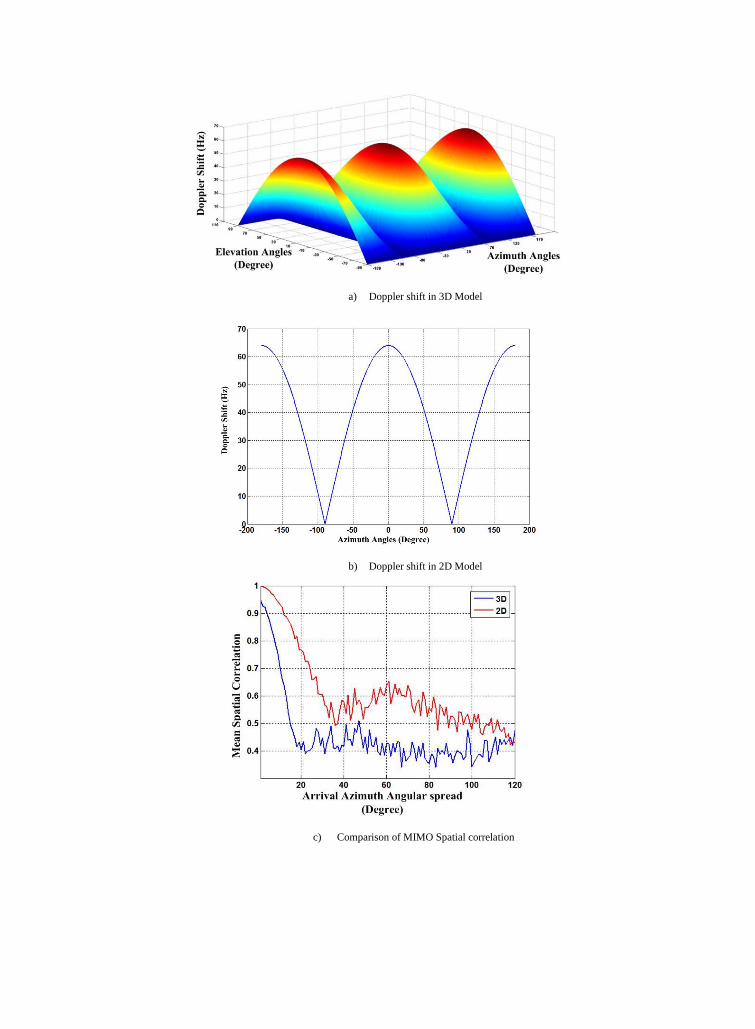
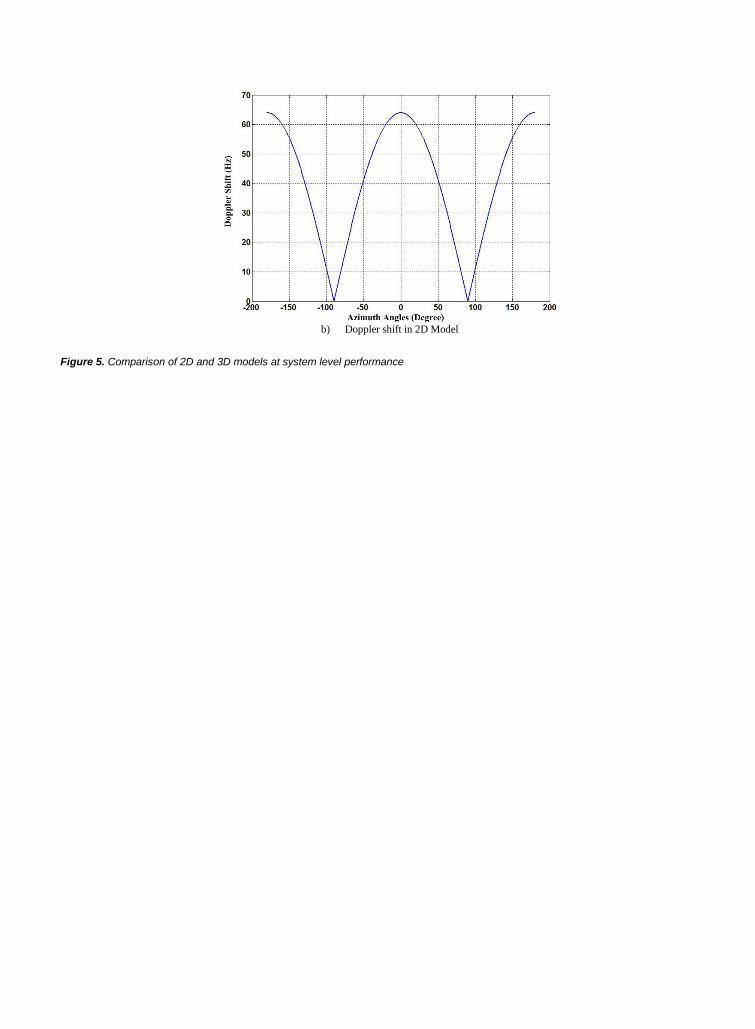
Doppler shift
The Doppler frequency component, which is one of the parameters that characterizes the small-scale temporal fading, depends
on the angles of arrival at the UE and the UE velocity vector. The calculation of this vector is different in the case of a 3D channel
model. For 3D models the elevation angles of the multipath components also affect the Doppler shift (in addition to the azimuth angles
already present in 2D models). Based on the ITU model, the Doppler component is calculated as [10]:
𝑣𝑛,𝑚(2𝐷) =‖𝑣‖cos(𝜑𝑛,𝑚−𝜑𝑣)
𝜆0 (1)
In the 3D model the Doppler frequency is calculated as:
𝑣𝑛,𝑚(3𝐷) =‖𝑣‖cos(𝜑𝑛,𝑚−𝜑𝑣)cos(𝜁𝑛,𝑚−𝜁𝑣)
𝜆0(2)
where 𝑣, 𝜆0are the UE velocity (m/s) and wavelength (m) respectively. 𝜑𝑣is the UE direction of travel in the azimuth plane and 𝜁𝑣is
the UE direction of travel in the elevation plane. The variables 𝑛,𝑚 refers to the sub-path rays in the cluster based channel model.
This difference in the calculation of the Doppler shift affect the spatial fading experienced by UEs moving in a 3D environment.
Based on Equations (1) and (2), the overall Doppler shift experienced by UEs for different azimuth and elevation angles are presented
in Figures 5(a) and 5(b). These calculations assume absolute UE velocity of 30km/h.
MIMO Spatial Correlation
When MIMO techniques are deployed, large capacity gains can only be realized when the sub-channels are spatially de-
correlated. However in many real-world propagation environments, the theoretical gains are not achieved due to the significant spatial
correlation present in the channel. Our observations show that the 2D model clearly overestimates the level of spatial correlation,
when the elevation angle is not modelled. Exploiting the elevation plane can further enhance system performance by benefiting from
the richness of the 3D channel. The deployment of a 3D channel model requires the application of 3D antenna patterns in the channel
generation process. In order to show the difference in spatial correlation between 2D and 3D channel models, Figure 5(c) demonstrates
the mean correlation at the UE for a range of azimuth angular spreads based on random channel generation for large number of UEs
based on the developed 3D ITU model and the existing 2D ITU model. It is clearly shown that the 3D channel model results in lower
spatial correlation.
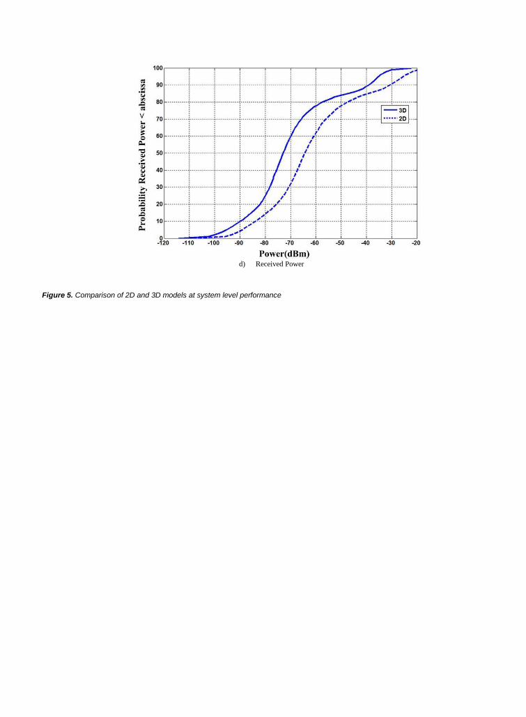
Total received power
Propagation in 3D also impacts the total received power, especially when 3D antenna patterns are included in the analysis. The
CDF of the total received power for the 2D and 3D channel models are shown in Figure 5(d). A difference in the total received power
between the 2D and 3D models is observed. This data assumes the antenna patterns and the propagation conditions deployed in [15].
The 2D model results in higher power levels compared to the 3D model. This is because the arrival rays in the 2D ITU model are
always interpolated at fixed elevation angle. In the 3D ITU model, the rays’ elevation dimension is considered and the interpolation
of the antenna gain is considered at all azimuth and elevation angles. At some elevation angles the antenna gain is high, while at other
angles the gain is much lower.
a) Doppler shift in 3D Model
b) Doppler shift in 2D Model
c) Comparison of MIMO Spatial correlation

d) Received Power
Figure 5. Comparison of 2D and 3D models at system level performance
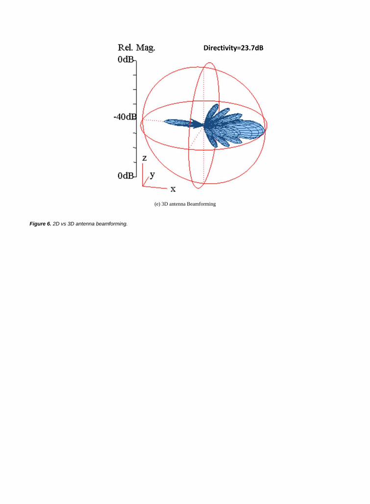
3D MIMO and beamforming
Three-dimensional MIMO (3D MIMO) is an effective step towards massive MIMO, without the need to employ vast numbers
of antenna elements at the BS. The vertical dimension can be utilized by the antenna array, with the down tilt of the antenna becoming
a significant channel parameter. A typical 2D antenna is used to cover a sector of 120o in the horizontal plane. Compared to 2D
channel propagation, in a 3D model the scatters are no longer located in the same plane as the antenna elements. The incorporation
of the elevation plane in the modelling of the departure and arrival angles opens up more opportunities for 3D MIMO, where antenna
elements are deployed and spaced in the azimuth and elevation planes. Figure 6(a) and 6(b) demonstrate the concept of placing MIMO
antenna elements in 2D and 3D space respectively.
From an antenna perspective, exploiting the elevation plane (as well as the azimuth plane) is commonly referred to as 3D
beamforming [2] or Full Dimension MIMO (FD-MIMO). One way to exploit the additional degree of freedom offered by 3D channels
is to adapt the beam pattern for each UE in the vertical direction, thereby improving the signal strength at the receiver while also
reducing interference to other UEs. This is unlike the beamforming achieved with a linear array antenna in the horizontal dimension,
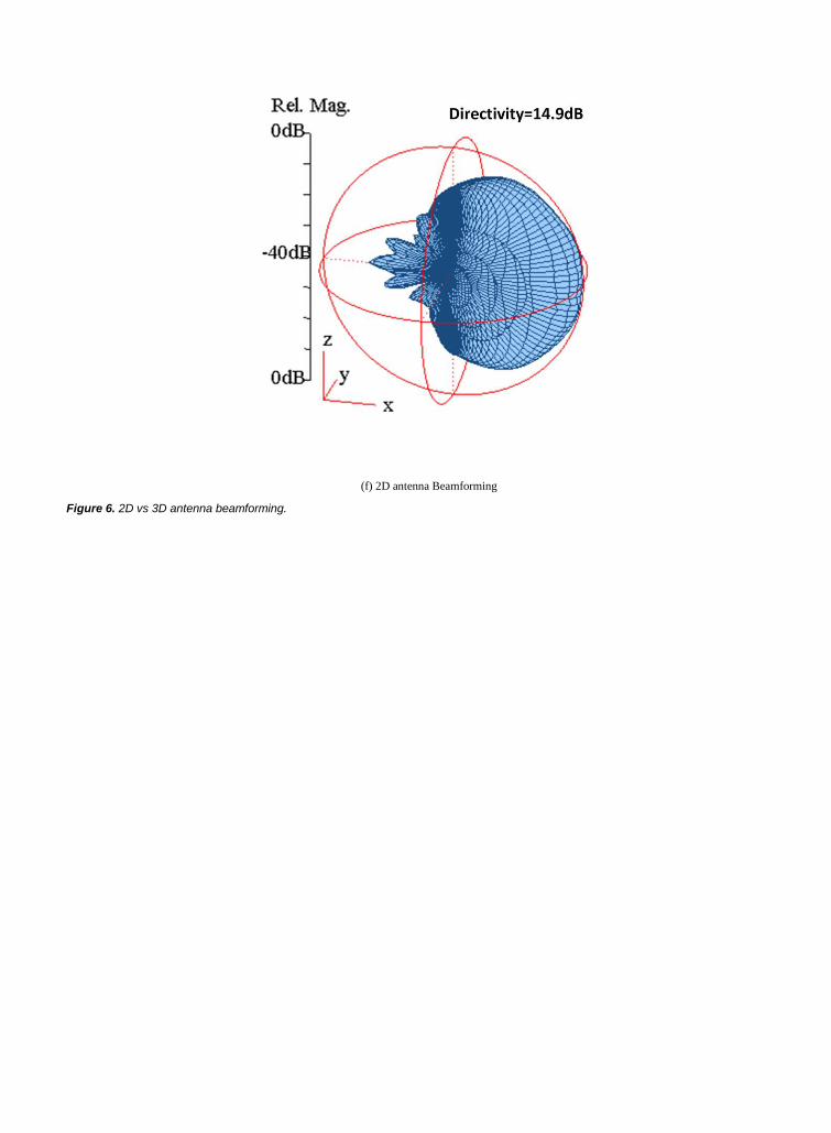
which does not give full-free space gain as illustrated in Figures 6(c) and 6(d). The differences between beamforming in 2D and 3D
planes are clarified in Figure 6(e) & 6(f). These figures show that 3D beamforming results in higher directive gain and narrower beam
widths towards a desired point in 3D space (defined by its azimuth and elevation angles).
(a) 2D antenna arrangement (b) 3D antenna arrangement
(c) 2D Beamforming (d) 3D Beamforming

(e) 3D antenna Beamforming (f) 2D antenna Beamforming
Figure 6. 2D vs 3D antenna beamforming.
The higher directive gain obtained from 3D MIMO, when combined with an efficient beamforming algorithm, results in higher
system performance compared to azimuth-only beamforming. Analogue 3D beamforming represents a promising technology for 5G
systems for coverage enhancements and inter-cell interference cancellation.
Conclusions
This article has presented an overview of some the researches in 3D channel modelling and highlighted the relevant contribution
of some standardized channel models. It also discussed the benefits of the 3D model and its impact on system level performance. The
proposed 3D channel model is presented with explanation of the modelled channel parameters. To illustrate the subjects covered in
this article the authors have released open source code at sourceforge.net that implements the proposed 3D extension to the 3GPP/ITU
model.
References
[1] J. Fuhl, J.Rossi, and E. Bonek, "High-resolution 3-D direction-of-arrival determination for urban mobile radio," IEEE Transaction Antenna and
propagation, vol. 45, pp. 672-682, 1997. [2] Z. Hu; R. Liu; S. Kang; X. Su; J. Xu, "Work in progress: 3D beamforming methods with user-specific elevation beamfoming," 9th International
Conference on Communications and Networking in China (CHINACOM), 2014, pp. 383-386, Aug. 2014.
[3] T. Aulin, "A Modified Model for the fading Signal at A Mobile radio Channel," IEEE Transaction on Vehicular Technology, vol. 28, pp. 182-204, 1979.
[4] A. Juchar, J. Rossi, and E. Bonek, "Directional macro-cell channel characterization from urban measurements " IEEE Transaction Antenna and
propagation, vol. 48, pp. 137-146, 2000. [5] K. kalliola, K. Sulonen, and H. Laitinen, "Angular power distribution and mean effective gain of mobile antenna in different propagation
environments," IEEE Transaction on Vehicular Technology, vol. 51, pp. 823-838, 2002.
[6] J. Laurila, K. kalliola, and M. Toelstch, "Wide-band 3-D Characterization of Mobile radio Channels in Urban Environment " IEEE Transactions on Antennas and Rogation, vol. 50, 2002.
[7] K. kalliola, H. Laitinen, P. Vainikainen, and M. Toeltsch, "3-D double-directional radio channel characterization for urban macrocellular
applications " IEEE Transaction Antenna and propagation, vol. 51, pp. 3122-3133, 2003. [8] L. hentila, "Elevation Extension for a geometry-Based Radio Channel Model and its Influence on MIMO Antenna Correlation and Gain
imbalance. ," presented at the 5th European Conference on Antenna and Propagation (EUCAP), 2011.
[9] R1-122034, "Study on 3D channel Model for elevation beamforming and FD-MIMO studies for LTE," 3GPP TSG RAN2012. [10] WINNER+ Final Channel Models, D5.3 V1.0, Jun. 2010.
[11] 3GPP TR 130500, "Detailed 3D Channel Model for LTE," 3GPP, St.Julian’s Malta 3GPP TSG RAN Meeting #72, 2013.
[12] E.K. Tameh and A.R. Nix, “The use of measurement data to analyse the performance of rooftop diffraction and foliage loss algorithms in a 3-D integrated urban/rural propagation model,” 48’Th IEEE VTC, May 1998
[13] Q. Nadeem, A. Kammoun and M. Alouini, “A Generalized Spatial Correlation Model for 3D MIMO Channels Based on the Fourier Coefficients
of Power Spectrum,” IEEE Transactions on Signal Processing, April.2015 [14] ITU-R M.2135-1, “Guidelines for evaluation of radio interface technologies for IMT-Advanced”, Dec. 2009.
[15] R. Almesaeed, A. Ameen, A. Doufexi, N. Dahnoun and A. Nix, “A Proposed 3D Extension to the 3GPP/ITU Channel Model for 800MHz and 2.6GHz bands”, 8th IEEE EUCAP, April 2014.

Reham Almesaeed received the B.Sc in Computer Engineering from IT College, University of Bahrain, Bahrain in 2008. And the
MSc degrees in Electrical Engineering from the University of Bristol, Bristol, UK in 2010. She is currently lecturer is Computer
Engineering Department at University of Bahrain. Her research interests include wireless channel modelling, wireless local area
networks, Long-Term Evolution, fifth-generation communications systems; mmWave communications, and massive MIMO.
Araz Sabir Ameen received the Ph.D. degree in Electrical and Electronic Engineering from the University of Bristol, U.K., in 2015.
Currently he is lecturer in Wireless Communication at the University of Sulaimani, Kurdistan, Iraq. His research interests include
orthogonal frequency division multiplexing, vehicular communications; multiple antenna systems; Long-Term Evolution -Advanced
and fifth-generation communication system, Adaptive 3D beam-forming, wireless channel modelling, intercell interference modelling
and mitigation techniques.
Evangelos Mellios is currently a Lecturer in Electrical and Electronic Engineering at the University of Bristol. Evangelos joined
the Communication Systems and Networks Research Group where he completed his PhD in 2013, and he subsequently worked as a
Research Assistant in on-body sensing and wireless communications within the SPHERE Project (a Sensor Platform for HEalthcare
in a Residential Environment).
Angela Doufexi received the Ph.D. degree from the University of Bristol, U.K., in 2002. She is currently a Reader in wireless networks
at the University of Bristol. Her research interests include orthogonal frequency-division multiplexing; multiuser diversity and
resource allocation, wireless local area networks, vehicular communications; multiple antenna systems; Long-Term Evolution and
fifth-generation communications systems; mmWave communications; massive MIMO; and multimedia transmission. She is the author
of over 150 journal and conference papers in these areas.
Prof. Andrew Nix received BEng and PhD degrees from the University of Bristol in 1989 and 1993 respectively. His PhD was entitled
“A Fundamental Investigation into Short Range High Capacity Mobile Data Transmission”, and compared time-domain and
frequency domain equalisation strategies for use in Wireless Local Area Networks (WLANs). Over a period of 23 years he have
supervised 50+ PhD students to completion and published in excess of 450 refereed journal and international conference papers.
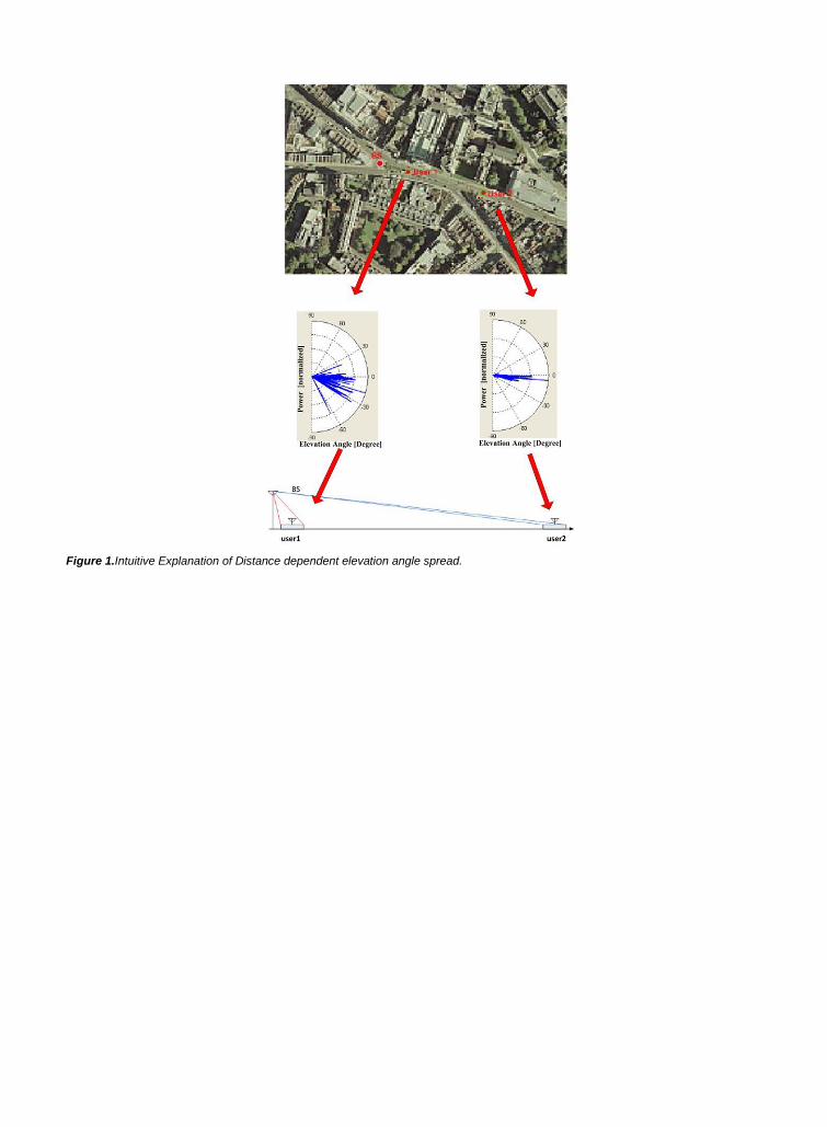
Figure 1.Intuitive Explanation of Distance dependent elevation angle spread.

a) Mean of arrival elevation spread vs distance
Figure 2. Analysis of predicted elevation angular spread.

b) Variance of arrival elevation spread vs distance
Figure 2. Analysis of predicted elevation angular spread.

c) Arrival elevation spread for different BS heights in LOS
Figure 2. Analysis of predicted elevation angular spread.

d) Arrival elevation spread for different BS heights in NLOS
Figure 2. Analysis of predicted elevation angular spread.
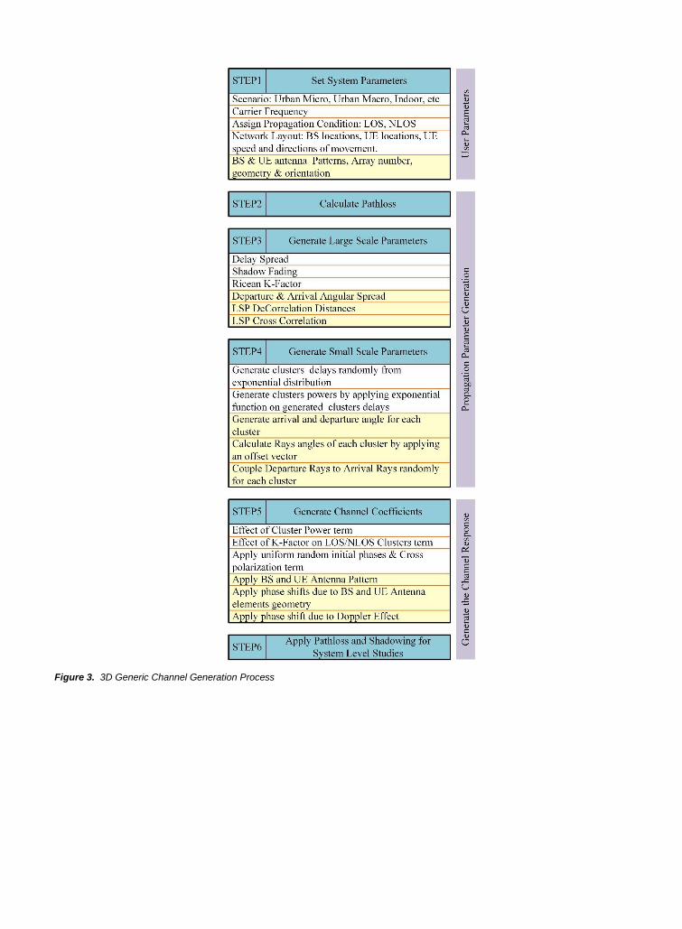
Figure 3. 3D Generic Channel Generation Process
a) Urban Macro cell
Figure 4. Comparison of CDFs of RMS arrival angular spreads.

a) Urban Pico cell
Figure 4. Comparison of CDFs of RMS arrival angular spreads.

a) Doppler shift in 3D Model
Figure 5. Comparison of 2D and 3D models at system level performance
b) Doppler shift in 2D Model
Figure 5. Comparison of 2D and 3D models at system level performance

c) Comparison of MIMO Spatial correlation
Figure 5. Comparison of 2D and 3D models at system level performance
d) Received Power
Figure 5. Comparison of 2D and 3D models at system level performance

(a) 2D antenna arrangement
Figure 6. 2D vs 3D antenna beamforming.

(b) 3D antenna arrangement
Figure 6. 2D vs 3D antenna beamforming.

(c) 2D Beamforming
Figure 6. 2D vs 3D antenna beamforming.

(d) 3D Beamforming
Figure 6. 2D vs 3D antenna beamforming.
(e) 3D antenna Beamforming
Figure 6. 2D vs 3D antenna beamforming.
(f) 2D antenna Beamforming
Figure 6. 2D vs 3D antenna beamforming.


![Fafoutis, X., Tsimbalo, E., Mellios, E. , Hilton, G. S ......on-body accelerometers and gyroscopes. KNOWME [16] consistsofanetworkofmultipleon-bodysensors,includ-ing accelerometers](https://img.dokumen.tips/doc/110x75/5f38b6e1a2a9727f61718b28/fafoutis-x-tsimbalo-e-mellios-e-hilton-g-s-on-body-accelerometers.jpg)