Embed Size (px)
Citation preview

1Assembly manual - Allukemi Life™
Allukemi Life™
Assembly manual

2 Assembly manual - Allukemi Life™
1. Introduction. Page 3 1.1 From the designer to the consumer.
2. Product description. Page 4 2.1 Functional diagram 2.2 Type of element 2.3 Additional elements
3. Description of components. Page 5
4. Assembly. Page 12 4.1 Recommendations 4.2 Fitters 4.3 Assembly kit 4.4 Movement and storage 4.5 Phases 4.6 Support assembly 4.7 Securing of fixed end lf01 and middle pieces lf04 4.8 Securing of adjustable angle transmission elements lf06 4.9 Tensioner mounting LF14 4.10 Cable head closure with coin box (cap with cable grip wedge) 4.11 Inserting the cable into middle pieces and into the adjustable angle transmission 4.12 Mounting the absorber/tensioner block LF70 4.13 Tightening the free end of the cable 4.14 Tensioning line 4.15 Plumbing line
Table of contents.
4.16 Sign LF00 installation
5. Guarantees. 18 5.1 Duration 5.2 Exclusion 5.3 Limitations 5.4 Responsibility 5.5 Renewal 5.6 Testing and maintenance
5. References. 19 6.1 Manuals 6.2 Regulations 6.3 Technical standards 6.4 National regulations 6.5 nternet sites

3Assembly manual - Allukemi Life™
1. Introduction.
For works performed in places where there is danger of falls, in order to allow the operator to perform maintenan-ce operations to move easily along the work area, a fall arrest system should be installed. The system in question, in addition to being safe, should be ergonomic, namely, for “convenient” use for the operator.The system in question must be provided in the Techni-cal Coverage Report (ETC) that is drawn up by the He-alth & Safety Coordinator at the design phase (CSP), in agreement with the designer, and is an integral part of the project both of the technical dossier and of the work. The ETC is therefore composed of various documents, with re-levance to different subjects, in particular:
• Coordinator/technician: graphics with routes and access points to the roofing highlighted, technical report with the design solutions adopted, calculation report for supports and mountings to the structure.• Manufacturer: product certification, manual of installation, use and maintenance.• Installer: declaration of conformity of the works performed.
From the designer to theconsumer. 1.1
With regard to the points mentioned above, the objecti-ves of Genesi Italia are to create a direct line between the designer of the system and the final user, passing by the manufacturer and installer by means of:• Study of the line through software with immediately understandable graphical interface and return of the elements that constitute the system (as an alternative to the consultancy of our technical office).• Supply of the elements provided for the entire system directly from Genesi Italia or from the chain of authorised resellers.• Installation with simple procedures according to the Installation Manual by installers trained by Genesi Italia (subject of this document).• Use and maintenance of the line according to the Manual of Operation and Maintenance.

4 Assembly manual - Allukemi Life™
2. Product description.ALLUKEMI LIFE™ life lines comply with the safety require-ments set out in standard EN 795:2012 for anchor devices within the C-type, or rather anchoring devices that use ho-rizontal flexible anchor lines with a maximum inclination of 15° from the horizontal. The device is also in compliance with safety requirements set out in technical specifications CEN/TS16415: 2013 which establishes the tests and re-quirements for devices used simultaneously by multiple users. It consists of a wire cable stretched between two or more elements fixed to adequately sized supports, with an energy absorber mounted on the end of the line, which dampens the energy in the event of a fall of the opera-tor. The passage of the intermediates, as dictated by the principle of the ergonomics reported in Legislative Decree 81/2008 takes place without the disconnection of the ope-rator, but with an easy and simple sinusoidal movement.The maximum line length is 200 m and the maximum di-stance between two supports is 15 m and the minimum is 3 m. The supports of the life line are sized by a qualified engineer in order to bear the load transmitted by the life line in the event of a fall. These can be mounted on beams in reinforced concrete, wood or steel, directly or with spe-cial steel backplates. It follows that the beams must also be able to withstand these loads and this resistance must be ensured in the design phase or with checks directly on site. This type of system is certified for the concurrent use by 3 operators that in the event of a fall generate on the end pieces a maximum force of 21.6 KN. The operator that
uses this system must wear a harness that conforms to the EN 361 standard and a double lanyard that complies with the EN 354 equipped with energy absorber according to EN 355. Where it is possible to cover distances greater than the 2 m, limit of the lanyard, it is possible to use a retraction device according to EN 360, a guided fall arrest device with flexible guide according to EN 353-2. Attach-ment to the line occurs with a connector that conforms to the standard EN 362. In any case, the user must be a person trained in the use of systems and their individual devices, attested by an appropriate course. The choices on the use of the suitable device associated with the life line must be made by the designer in relation to the correct assessment of the air draft and the pendulum effect.This system is non-deformable and can be used for the eventual recovery of the operator in the event of a fall wi-thin 20/25 minutes to avoid serious permanent damage, with appropriate recovery kit that complies with the EN 341 standard.All components are made of aluminium alloy. They may also be lacquered with epoxy paint as a base and any de-sired RAL colour paint, with the exception of mounting sy-stems that are in stainless steel.The life line in question has been tested with both static and dynamic tests by the Apave Certifying Organisation, enabled according to standard EN 364 and the elements used at times are in accordance with those tested.Below is a detailed description of the system.
Functional diagram. 2.1 Type of element. 2.2
• standard supports art. SAP/SAS/SAU/PA for end pieces and adjustable corner transmissions;• standard supports art. SIAP/SIAS/SIAU/PIA for middle pieces;• specially sized supports;• flashings art.LF31;• end pieces type art.LF01;• middle pieces art.LF04 for long life lines, provided with a wheelbase of no more than 15 m;• adjustable corner transmissions art.LF06 if the life line is not straight;• energy/tensioner absorber lock art. LF70;• cap for cable containment (coil box);• stainless steel Ø10 mm cable art.LF11;• 1 mandatory sign art.LF00 at each access;• 1 identifier seal art.C35;• 1 tamper-proof seal art.C34.
Additional elements. 2.3
• individual anchor points to allow landing on roofing and/or to prevent the pendulum effect.

5Assembly manual - Allukemi Life™
3. Description of components.
End piece Art.LF01 3.1.1
The end piece is used to create start and end points of the life line and must be fixed on a suitable standard support or special supports.
Material: aluminium die-cast, alloy EN AB 46100Geometry: see figureNet weight: 0.74 KgEquipment: 4 holes Ø6.5 with cylindrical slot Ø16.5 in the base plate special pin or cotter pin for mounting the energy absorber/tensioner or the cable with thimble Mounting: 4 self-tapping 6.3X65 mm hex head screws provided with flat washers with Ø16 waterproof seal
Middle piece Art.LF04 3.1.2
The middle piece is used for lines longer than 15 m, posi-tioned at most every 15 m, and allows safe passage of the user without having to unclip from the life line. This piece must be fastened into a standard middle support or spe-cial supports.
Material: aluminium die-cast, alloy EN AB 46100Geometry: see figureNet weight: 0.90 KgEquipment: 4 holes Ø6.5 with cylindrical slot Ø16.5 in the base plateMounting: 4 self-tapping 6.3X65 mm hex head screws provided with flat washers with Ø16 waterproof seal NOTE: the maximum angle of horizontal deflection of the cable into the passage is 10°.
6 Assembly manual - Allukemi Life™
Description of components.
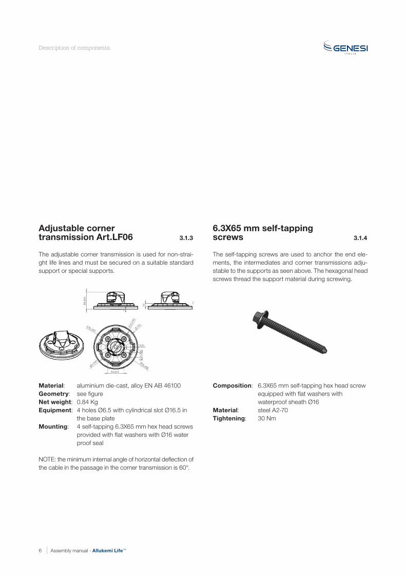
Adjustable cornertransmission Art.LF06 3.1.3
The adjustable corner transmission is used for non-strai-ght life lines and must be secured on a suitable standard support or special supports.
Material: aluminium die-cast, alloy EN AB 46100Geometry: see figureNet weight: 0.84 KgEquipment: 4 holes Ø6.5 with cylindrical slot Ø16.5 in the base plateMounting: 4 self-tapping 6.3X65 mm hex head screws provided with flat washers with Ø16 water proof seal NOTE: the minimum internal angle of horizontal deflection of the cable in the passage in the corner transmission is 60°.
6.3X65 mm self-tappingscrews 3.1.4
The self-tapping screws are used to anchor the end ele-ments, the intermediates and corner transmissions adju-stable to the supports as seen above. The hexagonal head screws thread the support material during screwing.
Composition: 6.3X65 mm self-tapping hex head screw equipped with flat washers with waterproof sheath Ø16Material: steel A2-70Tightening: 30 Nm

7Assembly manual - Allukemi Life™
Description of components.
Energy absorber/tensionerblockArt. LF70 3.1.5
The LF70 energy absorber/tensioner allows for a reduction of kinetic energy in the event of a fall of one or more opera-tors connected to the line. Its innovative composition with polymer blend NR70 printed components ensures high energy absorption and complete elastic return when the flexible line is discharged.Any falls or entering into service of the line is signalled by the output of two red plastic pieces from the contrast pla-te. A cap is mounted on the fork, inside which the cable is wound around a tightening wedge.
Material: bracket, EPDM mould containment plates and relative stainless steel tightening hardware NR70 “rubber” laminated springsSupply: bracket for securing to the end elements and cap for securing of the cable (COIN BOX)
Tensioner blockArt. LF14 3.1.5
The tensioner is used to ensure correct line tensioning.
Material: Tensioner body and relative forks in stainless steelNet weight: 1.19 kgSupply: threaded bar with eye Threaded bar with fork and cap for cable tightening Union housingTension: 14 cm

8 Assembly manual - Allukemi Life™
Cable Art.LF11 3.1.6
The steel cable allows anchoring of the operator at the life line.
Material: stainless steelDiameter: 10mmNet weight: 381 g/mResistance: >57KNComposition: 7 strands of 19 wires pre-shaped and crossed to the right with 1 blue coloured strand and internal strip of marked recognition Genesi Italia
Sign Art.LF00 3.1.7
The sign must be posted on every access point to the se-cured area.
Material: PVCInstallation: at every accessContents: Line type, serial number, maximum number of operators that can use the line life simultaneously on each individual stretch, air draft, date of entry into service of the life line, the obligation to use 3rd cat egory personal protective equipment (PPE), the name of the manufacturer, the name of the reseller, the name of the installer.
Description of components.

9Assembly manual - Allukemi Life™
Identifier seal Art.C35 3.1.8
The seal identifier is unique for each line life and must be positioned at the end of the same. The numbering is the same as reported on the sign described above and in the certification that accompanies the system.
Installation: at the end of each lineContents: serial number
Tamper-proof seal art.C34 3.1.9
The tamper-proof seal is used to lock the elements that characterise the life line.
Installation: on tensioner ring/box
Description of components.

10 Assembly manual - Allukemi Life™
Supports. 3.1.10
The supports serve to support loads on the end, middle and adjustable corner transmission components that de-velop in the event of an operator fall. They must therefore be sized in relation to said loads and to the structure on which they are assembled (reinforced concrete, wood, or steel). A series of so-called standard supports exist that adapt to most types of structures, with the possibility of also designing and constructing any other type of support, starting from a stainless steel base in which the alloy 7003 tower engages.
Type: standard supports SAP/SAS/SAU and PA plate for end pieces and adjustable corner transmissions standard supports SIAP/ SIAS/SIAU and PIA plate for middle pieces special supports ST10/ST20/ST30/ST40/ ST90 Material: base and tower in aluminium extrusion for standard supports Stainless steel base and tower in 7003 aluminium extrusion for special supportsWeight: variableGeometry: variable depending on typeHeights: 30/50/75/100 cmMounting: directly on the structure with M16 and M12 fixings and dual-component resin with special backplates (number and geometry varies according to type)
Flashings art.LF31. 3.1.11
Flashings are provided with a rubber sheath and must be supplied with the water infiltration prevention support. Al-ternatively, a direct plumbing can be provided instead of the flashing.
Installation: on the tower of each supportMaterial: PE-HD 20%TALCONet weight: 80 gGeometry: dimensions 300x230x104 mm with hollow centre 80x80 mm Supply: water seal sheath inside hollow partMounting: to be inserted into each support
NOTE: the flashing should be inserted on the tower before mounting of line components
Description of components.

11Assembly manual - Allukemi Life™
Mountings M16 3.1.12
The M16 fixings are used to anchor the supports according to the respective geometries of the bearing roof structure, whether it is in reinforced concrete, wood, or steel. They can be inserted directly in the roof with dual-component epoxy resin or with backplates.
Composition: threaded bar 16x175, grower washer and nut (in the case of backplates with double washer and double nut)Material: steel A4-70Tightening: 170 Nm
M12 bars 3.1.13
M12 bars are used to mount PA and PIA plates to the be-aring structure, whether it is in reinforced concrete, wood, or steel. They can be inserted directly in the structure with dual-component vinylester resin or with backplates.
Composition: bar 12x160 + grower washer + nut the number varies depending on the geometry of the element to be securedMaterial: steel A4-70Tightening: 70 Nm
Vinylester without styrenedual-component resinArt. RBS 345 mx 3.1.14
The dual-component, high-performance fast-curing epoxy resin is used in the insertion of threaded bars directly in the structure. For the technical data and instructions on use refer to the datasheet of the product.
Composition: vinylester without styrene with benzoyl peroxide as activatorContents: 345ml cartridge
Description of components.

12 Assembly manual - Allukemi Life™
4. Assembly.Recommendations. 4.1
Before fitting a site inspection is recommended to ascer-tain the real situation of the site on which the life line is to be mounted and to check for compliance with the planimetric report of the roof within which all the elements of the life line are highlighted.The maximum length of the line may not exceed 200m and the cable should not have an inclination greater than 15° from the horizontal.The maximum deflection of the line, in the event of a si-multaneous fall of 3 operators at the same point, is equal to 1.93 m (calculation subject to a variation of +-20%). It is essential to verify that there is no risk for the cable, under maximum deflection, of hitting objects with sharp edges that could compromise its integrity. It is therefore neces-sary to first assess air draft before any installation.The air draft must be greater than the fall height so that the falling person does not collide with any obstacles. The fall height corresponds to the sum of the following factors:• length of the rope «Ll»• energy absorber braking distance «Le» • cable deflection «d» (supplied by Genesi Italia technicians)• free space under the operator’s feet must be at least 1.0 m
In summary,
Ll + Le + d + 1.5 m +1.0 m < air draft
To allow for optimal use of the life line, it is advisable to position the cable at a height exceeding 20 cm from the roof surface.The installation must be carried out in compliance with the measures for the prevention of accidents in accordance with Legislative Decree 81/2008 - Consolidated Text on Health and Safety and on that indicated by the reference standard EN 795.
Fitters. 4.2
Installation of the ALLUKEMI LIFE™ line life includes the training of installers by an in-house technician to put into practice the correct methods for assembly. The fitters affi-liated to the partners of Genesi Italia are obliged to draw up their own Risk Assessment Document (DVR) from which the risks linked to the fitting of the life line and the coun-ter-measures adopted to reduce the likelihood of this hap-pening are drawn.After installation, the installer should
Assembly kit. 4.3
The main work equipment to perform correct installation:• kit for holes: rotopercussion drill, pipe cleaner, blower, resin gun;• Torque wrench to tighten the nuts on the threaded bars;• open polygonal ratchet key 24 mm;• tensioner (frog and TIRFOR) for cable pre-tensioning;• line stretcher hook ART. LF12 to be mounted on the LF10 lock to allow attachment of the tensioner;• sensors kit, composed of: sensor verification anchorages art. SVAN, tension verification sensor art. SVTE, traction verification sensor art. SVTR all can be connected with the special handheld art. PALM for the reading of data;• hand tools (pliers, various keys).

13Assembly manual - Allukemi Life™
Movement and storage. 4.4
Extreme caution is recommended during the handling and storage of all the components of the life line to avoid creating problems of corrosion. All the components weigh less than 25 kg, maximum weight allowed for the manual handling of loads by a single operator. When the weight of the components, especially of special supports, exceeds this value, movement with two operators or crane must be performed. These operations are also an integral part of the DVR.
Phases. 4.5
The phases described in this chapter are valid for the mounting of the pure line into the desired position and must be carried out in complete safety, thus complying with the instructions contained in the Safety Operational Plan (SOP) drawn up by the installer, in conformity with the Safety and Coordination Plan (SCP) drawn up by the Sa-fety Coordinator at the Design phase (SCD) or by the Se-curity Coordinator during the Implementation stage (SCI) where these two figures are present. If the area has not been complete secured, installation must begin with the individual anchor points to perform the lifts in the desired area or use a temporary life line.The steps of installation of this line shall be construed as excluding all those operations that are used to prepare the work area or to access the same.
Support assembly 4.6
The mounted support can be chosen from our current ran-ge or can be calculated based on the type of roof on which it will be mounted using the M16 mountings.
Direct mounting on wood or reinforced concrete (for each threaded bar):• drill on the roofing a hole Ø18 of length 10 cm with roto percussion drill;• clean the same with a special brush, making it rotate, and then use a manual pump in such a way as to remove the dust from the walls of the hole (repeat the operation more than once);• slowly insert the dual-component vinylester resin from the bottom of the hole upward to prevent the formation of air bubbles;• insert the M16 threaded bar rotating the same;• position the support and leave the resin to harden according to the times indicated on the package; • fit the washer and the nut on the threaded bar;• tighten the nut applying a torque of 170 Nm.
Mounting with backplate on steel (for each threaded bar):• position the support and relative backplate, clamping the steel structure;• insert the M16 threaded bar with grower washer and nut both on the top and on the bottom and tighten the nut, applying a torque of 170 Nm.
Direct mounting on large hollow tiles + hood with electric welded mesh (for each threaded bar):
• drill on the roofing a hole Ø20 with rotopercussion drill, leaving the lower bottom of the hollow tile integral• clean the same with a special brush, making it rotate, and then use a manual pump in such a way as to remove the dust from the walls of the hole (repeat the operation more than once)• insert a pre-shaped mesh liner to contain the resin• slowly insert the dual-component epoxy resin from the bottom of the hole upward to prevent the formation of air bubbles and too much mesh liner leakage• insert the threaded bar rotating the same• position the support• insert threaded bar M16 with a grower washer and nut• tighten the nut applying a torque of 170 Nm
Note: it is the task of the installer to verify the correct tight-ness of the mountings; it is therefore advisable to perform an extraction test with art. SVAN sensor connected to han-dheld PALM for reading of the data.
Assembly.

14 Assembly manual - Allukemi Life™
Securing of fixed end LF01 andmiddle pieces LF04 4.7
After installation of the supports, mount them on the end pieces art. LF01and middle pieces art.LF04 with the ap-propriate self-tapping hexagonal screws as follows:• align the 4 holes of the support with those of the elements bearing in mind that they are symmetrical thus adjustable every 90°• inert the screws with the sealing washers from the top to the limit switch
Note: before mounting line components on supports, pro-ceed with any insertion of flashings art. LF11
Securing of adjustable angletransmission elements LF06. 4.8
• After installation of the supports, mount the adjustable corner transmission elements art.LF06 on the same with the appropriate self-tapping hexagonal screws as follows:• align the 4 holes of the support with those of the elements bearing in mind that they are symmetrical thus adjustable every 90°• The central piece of the elements is adjustable depending on the angle of horizontal deviation desired thus align it as per requirement.• inert the screws with the sealing washers from the top to the limit switch
Assembly.

15Assembly manual - Allukemi Life™
Tensioner mounting LF14 4.9
Install tensioner LF14 at one end of the line to allow line tensioning.
• remove the end piece pin;• position the tensioner eye in axis to the hole present on the piece LF0 ;• re-insert the steel pin and the cotter pin, which will prevent accidental exiting.
Cable head closure withcoin box (cap with cable gripwedge) 4.10
After mounting of the elements in the line on supports, clo-se the end of the cable in the following manner:
• take the free end of the cable and insert it into the aluminium cap.
• bend the cable onto itself, making a slot, then have the free end come back out from the entrance slit.
• position the stainless steel wedge inside the slot and, at the same time, pull the dead head of the strand.
• cut any excess cable.
Assembly.

16 Assembly manual - Allukemi Life™
Inserting the cable into middlepieces and into the adjustableangle transmission 4.11
The next step is the inclusion of the life line cable, as fol-lows:• take the free head of the rope and pass it into any middle pieces and in the adjustable corner transmissions.
Mounting the absorber/tensioner block LF70 4.12
The energy/tensioner absorber block art. LF70 should be inserted at the other end of the line, on the end element as follows:
• insert the end piece pin into the absorber terminal and fasten by bending the cotter pin.
Tightening the free end ofthe cable. 4.13
Close the free end of the cable repeating the operations described in the paragraph “Cable head closure with coin box (cap with cable grip wedge)”.Before closing the free end of the cable:• with a mechanical tensioner, crimp the cable and, from the other, the end support, interposing the load cell and exert a pre-tension on the line equal to 700 N if the line is less than 30 m and 1100 N if the length is greater;• measure the cable, cutting any excess strand;• repeat the operation described in the paragraph;• release the mechanical tensioner.
Tensioning line. 4.14
The line is fully installed in all its parts It must be tensioned as follows:• apply the cable tension art. SVTE on the cable equipped with suitable handheld art. PALM for reading of the data;• with the open ratchet wrench, screw the hex 24 mm wrench positioned between the bracket of the absorber and the strike plate and simultaneously screw on the body of the tensioner LF14• for line sections less than 30 m, apply a tension of 750 N; for longer lines, apply a pre-tension of between 1000 and 1200 N
Assembly.

17Assembly manual - Allukemi Life™
Plumbing line. 4.15
Plumbing of the line consists of positioning the tamper-pro-of seal with art.C34 and the identifier seal art.C35 in the following manner:• insert the tamper-proof seal on the tensioner in the through-hole of a threaded bar cotter pin to block the tensioner housing;• insert the identifier seal at the absorber.
Sign LF00 installation. 4.16
Closing of the installation is completed with installation of the sign art.LF00, mandatory at each access point, di-splaying the information described above.
Note: where static “testing” of the line is required, carry out a test with suitable traction verification sensor art. SVTR equipped with handheld art. PALM for reading of the data.
Assembly.

18 Assembly manual - Allukemi Life™
5. Guarantees.Duration. 5.1
A 10 year warranty is agreed from the date of the delivery note on all the pieces in stainless steel or aluminium that make up our ALLUKEMI LIFE™ life lines and our anchor points making up the system.
Exclusion. 5.2
The guarantee will only be granted if: • the cable for ALLUKEMI LIFE™ lines life was provided by Genesi Italia;• material supplied has been fully paid;• the material was installed and has been used in accordance with the installation instructions and the technical instructions of Genesi Italia.
The guarantee will not be granted in cases where: • Our products are made from galvanised or zinc plated steel;• Our safety products include parts or accessories of external origin: in this case the agreed guarantee will be that of the supplier of the above parts.
The guarantee is excluded when the defect is caused:• by an intervention or a change made to the original system without the written permission of the manufacturer/reseller;• by use that is abnormal or that does not conform to the intended use of the equipment;• by defective installation not in compliance with drawings or performed to code;• by a client’s failure to communicate special conditions (pollution, temperature, number of users, etc.) regarding equipment use;• by breakage of a support hosting the anchoring device;• by the adding to our systems of parts produced by the buyer or from other sources other than Genesi Italia All our life lines must be sourced from Genesi Italia or manufactured with our consent, on the basis of our de signs;• by an event of force majeure or any event outside the control of the seller such as wars, lightning, etc.
Limitations. 5.3
In all cases our guarantee is limited to the replacement or repair of elements or equipment that are formally recogni-sed as defective by our technical service.If the repair is entrusted to a third party, this can only be
performed after acceptance by Genesi Italia of the repair quote.Any returning of equipment must be undertaken with the consent of Genesi Italia.The guarantee only applies to elements returned and as such does not cover the costs of removal and re-installa-tion of the equipment in the group in which it is integrated. The repair, replacement or modification of parts or equi-pment during the guarantee period can determine exten-sion of the guarantee.
Responsability. 5.4
Genesi Italia will be responsible, under the conditions of common law, for the material damage caused by your equipment or by your personnel.Repair of the material damage attributable to the seller is expressly limited to a sum that does not exceed the value of the equipment in question, subject of the order.By express convention, the seller and the customer mu-tually waive requiring the repair of the indirect and intangi-ble damage of any kind, such as operating losses, loss of earnings, costs of delay, reminder, removal and reinstalla-tion of the equipment, loss of future contracts, etc.
Renewal. 5.5
This guarantee of 10 years may be renewed at the request of the customer, after a technical inspection carried out, upon payment, by our services of the equipment installed.
Testing and maintenance 5.6
As far as possible, before each use, perform a visual exa-mination of the components of the life line.In case of doubt, ask the installing company, an inspection organisation or a maintenance engineer, authorised and responsible for this type of intervention, for an inspection.ALLUKEMI LIFE™ life lines require maintenance within 12 months of commissioning and from previous revisions as the device is EN795:2012 certified and therefore should be considered personal protective equipment in all respects. Inspection must be performed by a person authorised and delegated by Genesi Italia or by qualified persons/organi-sations.In the event of a fall the system shall be the subject of ne-cessary maintenance by an authorised and qualified per-son different from the users of the device.

19Assembly manual - Allukemi Life™
6. References.
Manuals. 6.1
Assembly Manual.
Regulations. 6.2
Technical standards. 6.3
EN 341:1993Personal protective equipment (PPE) against falls fromheights - Descent devices (transposition of Europeanstandard EN 341:1992)
EN 353-1:2003PPE against falls from heights - Guided type fall arresters including a rigid anchor line (transposition of European standard EN 353-1:2002)
EN 353-2:2003PPE against falls from heights - Guided type fall arresters including a flexible anchor line (transposition of European standard EN 353-2:2002)
EN 354:2003PPE against falls from heights - Lanyards(transposition of European standard EN 354:2002)
EN 355:2003PPE against falls from heights - Energy absorbers(transposition of European standard EN 355:2002)
EN 360:2003:PPE against falls from heights - Retractable fall arresters(transposition of European standard EN 360:2002)
EN 361:2003PPE against falls from heights - Body harnesses(transposition of European standard EN 361:2002)
EN 362:2005PPE against falls from heights - Connectors(transposition of European standard EN 362:2004)
EN 363:2008PPE against falls from heights - Individual systems for pro-tection against falls (transposition of European standard EN 363:2008)
EN 364:1993PPE against falls from heights - Test methods(transposition of European standard EN 364:1992)
EN 365:2005PPE against falls from heights - General requirements for instructions for use, maintenance, periodic examination, repair, marking and packaging (transposition of European standard EN 365:2004)
UNI-EN 795:2013Personal equipment for protection against falls - Anchoring devices (transposition of European standard EN 795:2012)
UNI CEN/TS16415:2013Personal equipment for protection against falls - Anchoring devices - Recommendations for anchoring devices for use by multiple people at the same time
National regulations. 6.4
Leg. Decree 81/2008 and subsequent additions and modificationsConsolidated text on health & safety
Internet sites. 6.5
www.genesibesafe.comOfficial site of the Manufacturer
www.uni.comItalian national site of unification

20 Assembly manual - Allukemi Life™
Genesi Italia
Via Donizetti, 109/11124030 Brembate di SopraBergamo - Italy
T. +39 035 0332049F. +39 035 [email protected]
Genesi Italia, Be Safe
Rev
. 02
- Fe
bru
ary
2015
genesibesafe.com