Embed Size (px)
Citation preview
The INL is a U.S. Department of Energy National Laboratoryoperated by Battelle Energy Alliance
INL-MIS--18-50073-Revision-0
Evaluation of 6061 AlAlloy MechanicalProperties of Fuel PlateCladding: HIP-BondedFuel Plates TEV-1758 R0
Randy R. Lloyd
March 2013

INL-MIS--18-50073-Revision-0
Evaluation of 6061 Al Alloy Mechanical Properties ofFuel Plate Cladding: HIP-Bonded Fuel Plates TEV-1758
R0
Randy R. Lloyd
March 2013
Idaho National LaboratoryIdaho Falls, Idaho 83415
http://www.inl.gov
Prepared for theU.S. Department of Energy
Under DOE Idaho Operations OfficeContract DE-AC07-05ID14517
Document ID: TEV-1758 Project No: 25228
Revision No: 0 Effective Date: 03/19/13
Technical Evaluation Study
TEV Title: Evaluation of 6061 Al Alloy Mechanical Properties of Fuel Plate Cladding: HIP-Bonded Fuel Plates
TEV No.: 1758
Performer: Randy Lloyd B120 3/13/2013 (Name) (Organization) Approved per email.
Checker1: Barry Rabin C610 3/14/2013
(Name) (Organization) Approved per email. Independent Peer Reviewer2:
Pavel Medvedev
C620 3/18/2013
(Name) (Organization) Approved per email.
Manager3: Timothy Hyde C610 3/15/2013
(Name) (Organization) Approved per email.
Owner4: Barry Rabin C610 3/18/2013
(Name) (Organization) Approved per email.
Cognizant Engineer4: Nicolas Woolstenhulme
C610 3/14/2013
(Name) (Organization) Approved per email.
1. Confirmation of completeness, mathematical accuracy, and correctness of data and appropriateness of assumptions. 2. Concurrence of method or approach. See definition, LWP-10106. 3. Concurrence of procedure compliance. Concurrence with method/approach and conclusion. 4. Concurrence with the document’s assumptions and input information. See definition of Acceptance, LWP-10300.
TEM-10300-1 09/30/2011 Rev. 02
TECHNICAL EVALUATION Page 2 of 18
Title: Evaluation of 6061 Al Alloy Mechanical Properties of HIP-Bonded Fuel Plate Cladding: HIP Bonded Fuel Plates
TEV No.: 1758 TEV Rev. No.: 0 Project File No.: 25228 Date: 03/19/13
REVISION LOG Rev. Date Affected Pages Revision Description
0 03/19/13 All See eCR 612637. New issue.
TEM-10300-1 09/30/2011 Rev. 02
TECHNICAL EVALUATION Page 3 of 18
Title: Evaluation of 6061 Al Alloy Mechanical Properties of HIP-Bonded Fuel Plate Cladding: HIP Bonded Fuel Plates
TEV No.: 1758 TEV Rev. No.: 0 Project File No.: 25228 Date: 03/19/13
1. Quality Level (QL) No. MSA-000186 Professional Engineer’s Stamp
N/A See LWP-10010 for requirements.
2. QL Determination No. 2
3. Engineering Job (EJ) No. N/A
4. eCR No. 612637
5. Building N/A
6. Site Area N/A 7. Introduction:
(SEE CONTENTS OF DOCUMENT.)
8. Conclusions/Recommendations: (SEE CONTENTS OF DOCUMENT.)
TEM-10300-1 09/30/2011 Rev. 02
TECHNICAL EVALUATION Page 4 of 18
Title: Evaluation of 6061 Al Alloy Mechanical Properties of HIP-Bonded Fuel Plate Cladding: HIP Bonded Fuel Plates
TEV No.: 1758 TEV Rev. No.: 0 Project File No.: 25228 Date: 03/19/13
CONTENTS BACKGROUND ..................................................................................................................................... 6
METHODS ............................................................................................................................................. 6
RESULTS .............................................................................................................................................. 7
DISCUSSION ...................................................................................................................................... 12
CONCLUSIONS/RECOMMENDATIONS ............................................................................................. 13
REFERENCES .................................................................................................................................... 14
APPENDICES Appendix A – Summary of Tensile Test Results ............................................................................................. 15 Appendix B – Measurement and Test Equipment Calibration............................................................... 18
TEM-10300-1 09/30/2011 Rev. 02
TECHNICAL EVALUATION Page 5 of 18
Title: Evaluation of 6061 Al Alloy Mechanical Properties of HIP-Bonded Fuel Plate Cladding: HIP Bonded Fuel Plates
TEV No.: 1758 TEV Rev. No.: 0 Project File No.: 25228 Date: 03/19/13
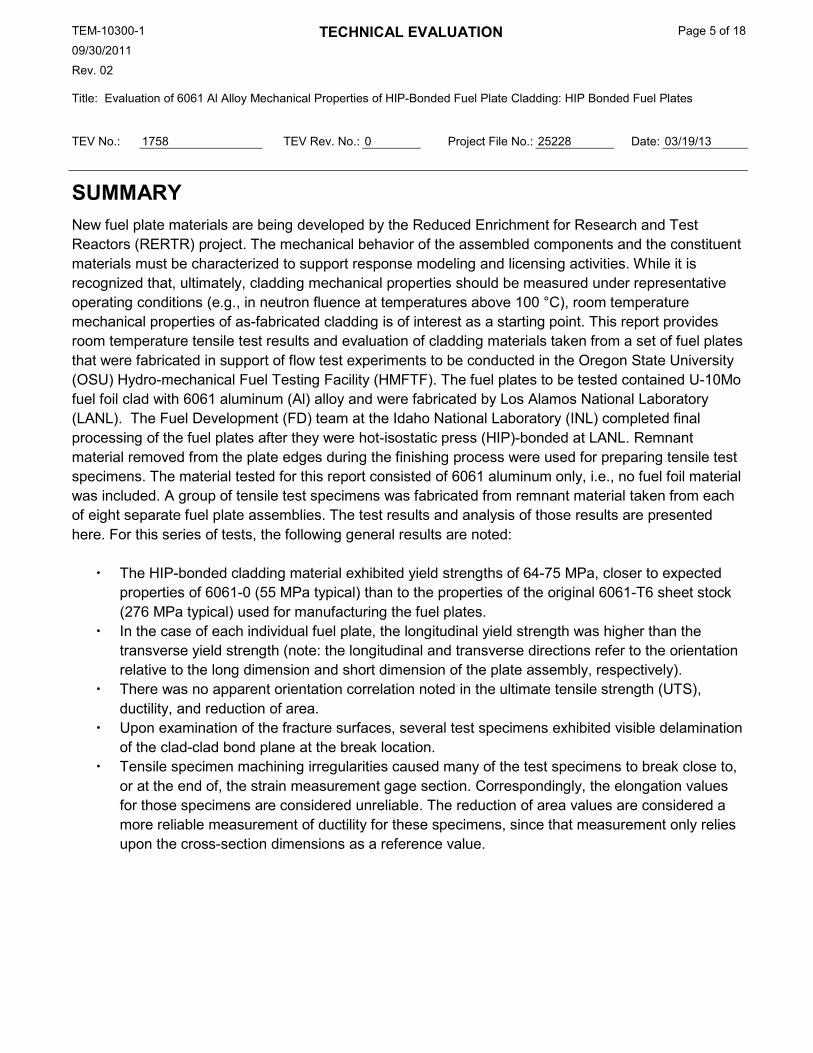
SUMMARY New fuel plate materials are being developed by the Reduced Enrichment for Research and Test Reactors (RERTR) project. The mechanical behavior of the assembled components and the constituent materials must be characterized to support response modeling and licensing activities. While it is recognized that, ultimately, cladding mechanical properties should be measured under representative operating conditions (e.g., in neutron fluence at temperatures above 100 °C), room temperature mechanical properties of as-fabricated cladding is of interest as a starting point. This report provides room temperature tensile test results and evaluation of cladding materials taken from a set of fuel plates that were fabricated in support of flow test experiments to be conducted in the Oregon State University (OSU) Hydro-mechanical Fuel Testing Facility (HMFTF). The fuel plates to be tested contained U-10Mo fuel foil clad with 6061 aluminum (Al) alloy and were fabricated by Los Alamos National Laboratory (LANL). The Fuel Development (FD) team at the Idaho National Laboratory (INL) completed final processing of the fuel plates after they were hot-isostatic press (HIP)-bonded at LANL. Remnant material removed from the plate edges during the finishing process were used for preparing tensile test specimens. The material tested for this report consisted of 6061 aluminum only, i.e., no fuel foil material was included. A group of tensile test specimens was fabricated from remnant material taken from each of eight separate fuel plate assemblies. The test results and analysis of those results are presented here. For this series of tests, the following general results are noted:
The HIP-bonded cladding material exhibited yield strengths of 64-75 MPa, closer to expected properties of 6061-0 (55 MPa typical) than to the properties of the original 6061-T6 sheet stock (276 MPa typical) used for manufacturing the fuel plates.
In the case of each individual fuel plate, the longitudinal yield strength was higher than the transverse yield strength (note: the longitudinal and transverse directions refer to the orientation relative to the long dimension and short dimension of the plate assembly, respectively).
There was no apparent orientation correlation noted in the ultimate tensile strength (UTS), ductility, and reduction of area.
Upon examination of the fracture surfaces, several test specimens exhibited visible delamination of the clad-clad bond plane at the break location.
Tensile specimen machining irregularities caused many of the test specimens to break close to, or at the end of, the strain measurement gage section. Correspondingly, the elongation values for those specimens are considered unreliable. The reduction of area values are considered a more reliable measurement of ductility for these specimens, since that measurement only relies upon the cross-section dimensions as a reference value.

TEM-10300-1 09/30/2011 Rev. 02
TECHNICAL EVALUATION Page 6 of 18
Title: Evaluation of 6061 Al Alloy Mechanical Properties of HIP-Bonded Fuel Plate Cladding: HIP Bonded Fuel Plates
TEV No.: 1758 TEV Rev. No.: 0 Project File No.: 25228 Date: 03/19/13
BACKGROUND Fuel plate modeling and reactor safety analyses require knowledge of the mechanical properties of the constituents comprising the fuel plates. The current and proposed fuel plate designs employ 6061 aluminum alloy as the cladding material. The modeling and safety analyses require accurate values for mechanical properties of the 6061 Al cladding in the subsequently subjected to the specified fuel plate finishing operations at INL. These HIP-bonded fuel plates were fabricated to support a series of fuel element flow tests to be conducted in the Hydro-Mechanical Fuel Testing Facility (HMFTF) at Oregon State University (OSU). Details about the experiment and fuel plate fabrication conditions are contained in PLN-3838, “Fabrication Control Plan for Test Plates; Intended for Oregon State University Hydro-Mechanical Fuel Testing Facility” [1]. The cladding samples tested in this study were prepared from the perimeter regions of the HIP-bonded plates, as specified in INL Drawing 771770, “Generic Test Plate Assembly Fuel Plate Assembly” [2].
METHODS As-fabricated fuel plates are typically sized to final dimensions by shearing away the excess Al cladding surrounding the perimeter of the fuel zone. The remnant “shear drops” can then be used to make test specimens of the bonded Al cladding. Specimens for conducting tensile tests were made from these remnant pieces. For this work, sub-size flat tensile specimens were prepared from the available shear drop remnants.
Each HIP-bonded fuel plate was identified by a unique identification code: two letters followed by four numerals. Individual test specimens were identified by the fuel plate code followed by a designation of “L” or “T”, corresponding to the specimen long dimension being parallel to the length (longitudinal) or width (transverse) dimensions of the fuel plate, respectively.
The specimens were fabricated according to the “sub-size” sheet-type specimen (rectangular cross-section) geometry shown in Figure 1 in American Society for Testing and Materials (ASTM) E8/E8M-11, “Standard Test Methods for Tension Testing of Metallic Materials” [3]. The specimens had the following nominal dimensions: overall length, 100 mm; reduced section length, 32 mm; reduced section width, 6.4 mm; and nominal thickness, 2.0 mm. For each of the fuel plates, one longitudinal (“L”) and one transverse (“T”) test specimen was prepared, as described above.
The prepared specimens were measured, marked, and tested according to ASTM E8/E8M-11 [3]. Specimen dimensions were measured with a calibrated digital micrometer with 0.01 mm resolution. For each specimen, thickness and width were measured at the center and near each end of the reduced section. The uniformity of the dimensions measured was less than desirable, and this is herein discussed in Section CONCLUSIONS/RECOMMENDATIONS.
The tests were performed at room temperature using an Instron 5984 universal test machine and Instron Bluehill 3 control software. Force was measured with a 5 kN Instron load cell calibrated by INL

TEM-10300-1 09/30/2011 Rev. 02
TECHNICAL EVALUATION Page 7 of 18
Title: Evaluation of 6061 Al Alloy Mechanical Properties of HIP-Bonded Fuel Plate Cladding: HIP Bonded Fuel Plates
TEV No.: 1758 TEV Rev. No.: 0 Project File No.: 25228 Date: 03/19/13
Standards and Calibration Laboratory (S&CL) in accordance with ASTM E4-10, “Standard Practices for Force Verification of Testing Machines” [4]. Specimen strain was measured with an extensometer with a 25.4 mm gage length, and 20% strain measuring range, and calibrated in accordance with ASTM E83-06, “Standard Practice for Verification and Classification of Extensometer Systems” [5], meeting accuracy Class B-2 (or better). The extensometer calibration and verification meet requirements of INL PLN-3347, “Extensometer Calibration Procedure” [6], and NQA-1. All reference standards used for calibration and verification are traceable to NIST primary standards. Specimen measurements were made with calibrated (INL S&CL) calipers. All transducer and support instrument calibration information is included in the test record for each test. Equipment calibration information is provided in Appendix B — Measurement and Test Equipment Calibration.
The tests were performed with an initial displacement rate of 2.5 mm/min, corresponding to an elastic stress rate of 5 MPa/s (nominal). Well after yielding (typically at about 1.5% indicated strain), the displacement rate was increased to 10 mm/min for the remaining test duration, as allowed by the test standard. Data were automatically logged, and the mechanical properties were automatically calculated by the Bluehill 3 software.
RESULTS The data for each individual test and a summary of the test results are available in an Excel workbook on the RERTR File Server at the following location: \\HMFTF\Cladding Tensile Testing\HIP-Bonded Plates\HIP-Bonded Fuel Plate Cladding Tensile Test Results - Feb 2013.xlsx. A summary of the specimens tested, specimen dimensions, and key tensile properties determined from each test specimen is provided in Appendix A — Summary of Tensile Test Results.
The individual specimen dimensions, width and thickness, were found to have substantial deviations along the reduced section length. The thickness was not machined, so thickness variations were an artifact of the HIP-bonding process. The widths at the same locations on both the “narrow” face and the “wide” face were measured. Most specimens had some taper in width along the length of the reduced section (narrower at one end, rather than at the center area). Most were also observed to have a small step in the width in the mid-thickness region. This was typically observed around the entire specimen perimeter, although it is only significant in the reduced section edges. It is suspected that this was caused by the machining process used to shape the specimen. During measurement with parallel caliper faces, it was observed that some of the specimen edges were not perpendicular to the faces.
Given the dimensional variability, an average area (for individual specimens) was used to calculate stress values. Analysis of the dimensional variations showed an average extreme spread of cross-section area of 7.3% for the longitudinal specimens (9.6% maximum, 5.8% minimum) and 4.5% for the transverse specimens (6.3% maximum, 1.5% minimum). These variations could produce, on average, between ±1.5 to ±2.5% deviation of reported stress values.
Baseline as-received mechanical properties measured for the cladding sheet stock are provided and discussed in TEV-1471, “Evaluation of 6061 Al Alloy Mechanical Properties for Fuel Plate Cladding: Roll
TEM-10300-1 09/30/2011 Rev. 02
TECHNICAL EVALUATION Page 8 of 18
Title: Evaluation of 6061 Al Alloy Mechanical Properties of HIP-Bonded Fuel Plate Cladding: HIP Bonded Fuel Plates
TEV No.: 1758 TEV Rev. No.: 0 Project File No.: 25228 Date: 03/19/13
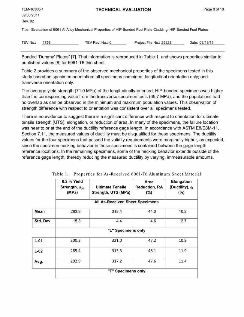
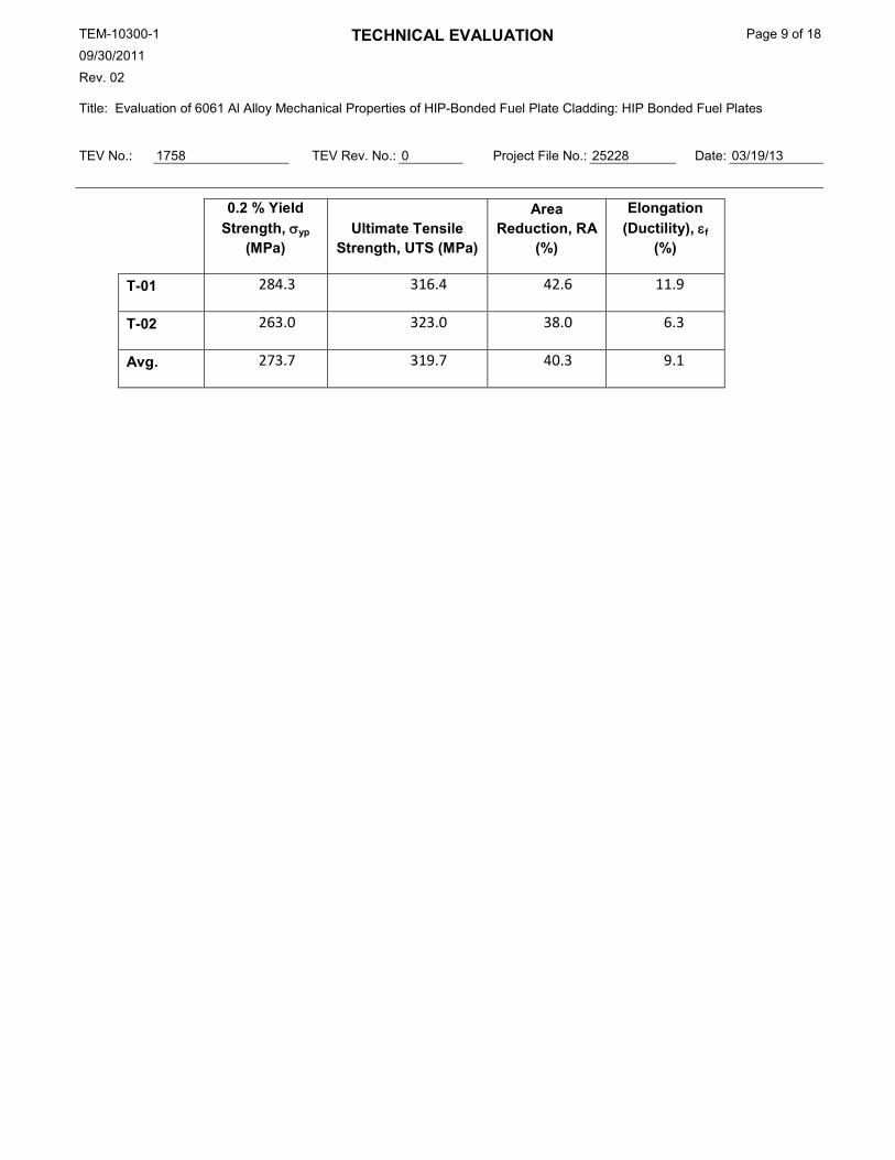
Bonded ‘Dummy’ Plates” [7]. That information is reproduced in Table 1, and shows properties similar to published values [8] for 6061-T6 thin sheet.
Table 2 provides a summary of the observed mechanical properties of the specimens tested in this study based on specimen orientation: all specimens combined; longitudinal orientation only; and transverse orientation only.
The average yield strength (71.0 MPa) of the longitudinally-oriented, HIP-bonded specimens was higher than the corresponding value from the transverse specimen tests (65.7 MPa), and the populations had no overlap as can be observed in the minimum and maximum population values. This observation of strength difference with respect to orientation was consistent over all specimens tested.
There is no evidence to suggest there is a significant difference with respect to orientation for ultimate tensile strength (UTS), elongation, or reduction of area. In many of the specimens, the failure location was near to or at the end of the ductility reference gage length. In accordance with ASTM E8/E8M-11, Section 7.11, the measured values of ductility must be disqualified for these specimens. The ductility values for the four specimens that passed the validity requirements were marginally higher, as expected, since the specimen necking behavior in those specimens is contained between the gage length reference locations. In the remaining specimens, some of the necking behavior extends outside of the reference gage length, thereby reducing the measured ductility by varying, immeasurable amounts.
Table 1. Properties for As -Rece ived 6061-T6 Aluminum Sheet Material
0.2 % Yield Strength, σyp
(MPa) Ultimate Tensile
Strength, UTS (MPa)
Area Reduction, RA
(%)
Elongation (Ductility), εf
(%)
All As-Received Sheet Specimens
Mean 283.3 318.4 44.0 10.2
Std. Dev. 15.3 4.4 4.6 2.7
"L" Specimens only
L-01 300.3 321.0 47.2 10.9
L-02 285.4 313.3 48.1 11.9
Avg. 292.9 317.2 47.6 11.4
"T" Specimens only
TEM-10300-1 09/30/2011 Rev. 02
TECHNICAL EVALUATION Page 9 of 18
Title: Evaluation of 6061 Al Alloy Mechanical Properties of HIP-Bonded Fuel Plate Cladding: HIP Bonded Fuel Plates
TEV No.: 1758 TEV Rev. No.: 0 Project File No.: 25228 Date: 03/19/13
0.2 % Yield Strength, σyp
(MPa) Ultimate Tensile
Strength, UTS (MPa)
Area Reduction, RA
(%)
Elongation (Ductility), εf
(%)
T-01 284.3 316.4 42.6 11.9
T-02 263.0 323.0 38.0 6.3
Avg. 273.7 319.7 40.3 9.1
TEM-10300-1 09/30/2011 Rev. 02
TECHNICAL EVALUATION Page 10 of 18
Title: Evaluation of 6061 Al Alloy Mechanical Properties of HIP-Bonded Fuel Plate Cladding: HIP Bonded Fuel Plates
TEV No.: 1758 TEV Rev. No.: 0 Project File No.: 25228 Date: 03/19/13
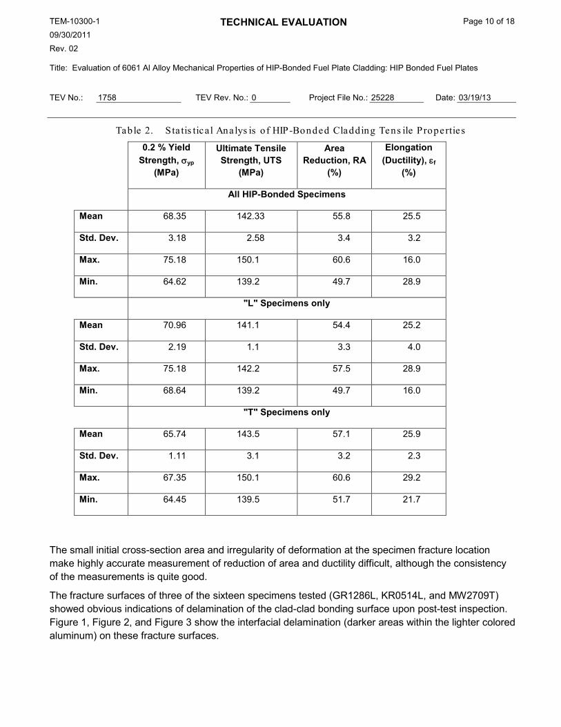
Table 2. Sta tis tical Analys is of HIP-Bonded Cladding Tens ile Properties
0.2 % Yield Strength, σyp
(MPa)
Ultimate Tensile Strength, UTS
(MPa)
Area Reduction, RA
(%)
Elongation (Ductility), εf
(%)
All HIP-Bonded Specimens
Mean 68.35 142.33 55.8 25.5
Std. Dev. 3.18 2.58 3.4 3.2
Max. 75.18 150.1 60.6 16.0
Min. 64.62 139.2 49.7 28.9
"L" Specimens only
Mean 70.96 141.1 54.4 25.2
Std. Dev. 2.19 1.1 3.3 4.0
Max. 75.18 142.2 57.5 28.9
Min. 68.64 139.2 49.7 16.0
"T" Specimens only
Mean 65.74 143.5 57.1 25.9
Std. Dev. 1.11 3.1 3.2 2.3
Max. 67.35 150.1 60.6 29.2
Min. 64.45 139.5 51.7 21.7
The small initial cross-section area and irregularity of deformation at the specimen fracture location make highly accurate measurement of reduction of area and ductility difficult, although the consistency of the measurements is quite good.
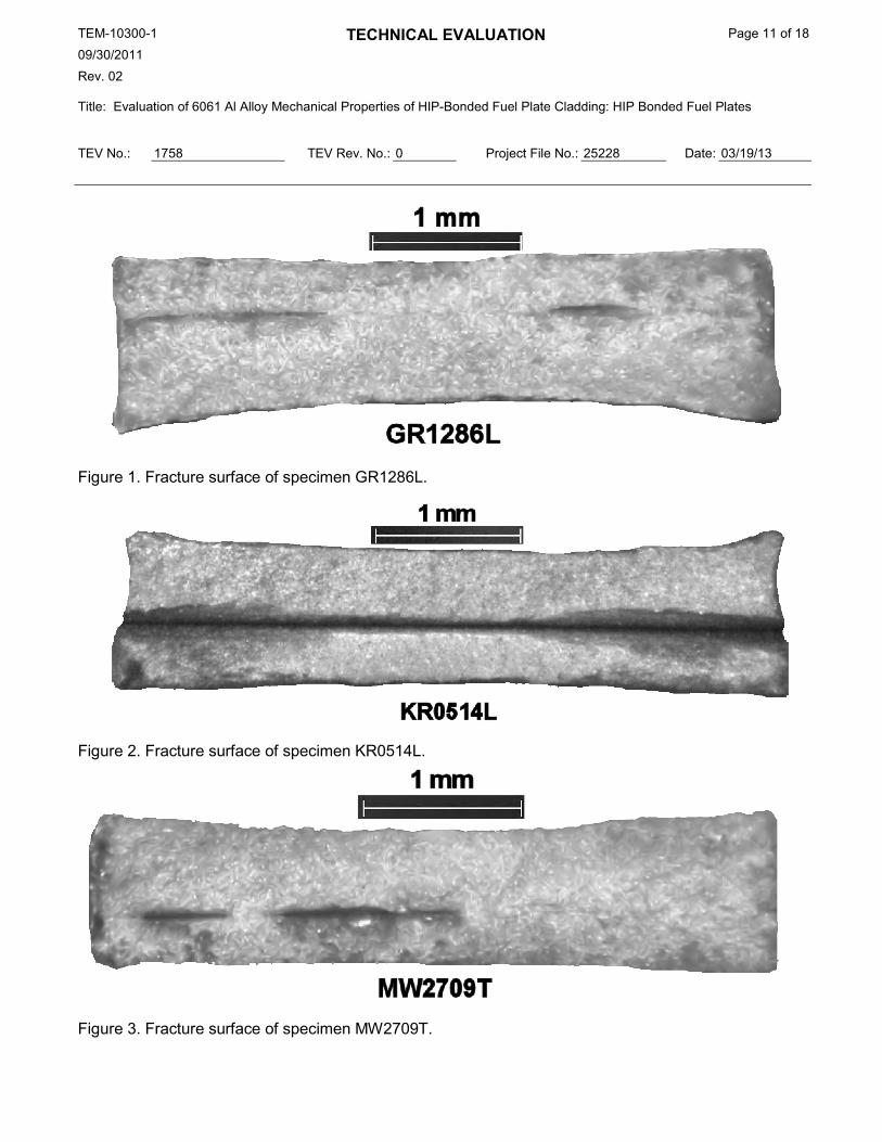
The fracture surfaces of three of the sixteen specimens tested (GR1286L, KR0514L, and MW2709T) showed obvious indications of delamination of the clad-clad bonding surface upon post-test inspection. Figure 1, Figure 2, and Figure 3 show the interfacial delamination (darker areas within the lighter colored aluminum) on these fracture surfaces.
TEM-10300-1 09/30/2011 Rev. 02
TECHNICAL EVALUATION Page 11 of 18
Title: Evaluation of 6061 Al Alloy Mechanical Properties of HIP-Bonded Fuel Plate Cladding: HIP Bonded Fuel Plates
TEV No.: 1758 TEV Rev. No.: 0 Project File No.: 25228 Date: 03/19/13
Figure 1. Fracture surface of specimen GR1286L.
Figure 2. Fracture surface of specimen KR0514L.
Figure 3. Fracture surface of specimen MW2709T.
TEM-10300-1 09/30/2011 Rev. 02
TECHNICAL EVALUATION Page 12 of 18
Title: Evaluation of 6061 Al Alloy Mechanical Properties of HIP-Bonded Fuel Plate Cladding: HIP Bonded Fuel Plates
TEV No.: 1758 TEV Rev. No.: 0 Project File No.: 25228 Date: 03/19/13
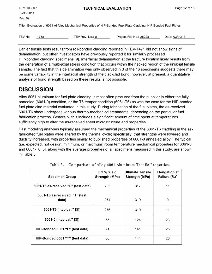
Earlier tensile tests results from roll-bonded cladding reported in TEV-1471 did not show signs of delamination, but other investigators have previously reported it for similarly processed HIP-bonded cladding specimens [9]. Interfacial delamination at the fracture location likely results from the generation of a multi-axial stress condition that occurs within the necked region of the uniaxial tensile sample. The fact that this delamination was only observed in 3 of the 16 specimens suggests there may be some variability in the interfacial strength of the clad-clad bond; however, at present, a quantitative analysis of bond strength based on these results is not possible.
DISCUSSION Alloy 6061 aluminum for fuel plate cladding is most often procured from the supplier in either the fully annealed (6061-0) condition, or the T6 temper condition (6061-T6) as was the case for the HIP-bonded fuel plate clad material evaluated in this study. During fabrication of the fuel plates, the as-received 6061-T6 sheet undergoes various thermo-mechanical treatments, depending on the particular fuel fabrication process. Generally, this includes a significant amount of time spent at temperatures sufficiently high to alter the as-received sheet microstructure and properties.
Past modeling analyses typically assumed the mechanical properties of the 6061-T6 cladding in the as-fabricated fuel plates were altered by the thermal cycle; specifically, that strengths were lowered and ductility increased, with properties similar to published properties of 6061-0 annealed alloy. The typical (i.e. expected, not design, minimum, or maximum) room temperature mechanical properties for 6061-0 and 6061-T6 [8], along with the average properties of all specimens measured in this study, are shown in Table 3.
Table 3. Comparis on of Alloy 6061 Aluminum Tens ile Properties .
Specimen Group 0.2 % Yield
Strength (MPa) Ultimate Tensile Strength (MPa)
Elongation at Failure (%)a
6061-T6 as-received “L” (test data) 293 317 11
6061-T6 as-received “T” (test data) 274 319 9
6061-T6 (“typical,” [8]) 276 310 11
6061-0 (“typical,” [8]) 55 124 23
HIP-Bonded 6061 “L” (test data) 71 141 25
HIP-Bonded 6061 “T” (test data) 66 144 26

TEM-10300-1 09/30/2011 Rev. 02
TECHNICAL EVALUATION Page 13 of 18
Title: Evaluation of 6061 Al Alloy Mechanical Properties of HIP-Bonded Fuel Plate Cladding: HIP Bonded Fuel Plates
TEV No.: 1758 TEV Rev. No.: 0 Project File No.: 25228 Date: 03/19/13
Roll-Bonded 6061 “L” [7] 65 115 26
Roll-Bonded 6061 “T” [7] 59 110 25
a. Ductility can be influenced by the material thickness. Published properties represent values for thin sheet, 1.5 mm or less in thickness.
Table 3 shows that the room temperature yield and tensile strengths of the HIP-bonded 6061 Al cladding specimens taken from the as-fabricated test plates are closer to the typical values for 6061-0 than the 6061-T6 used for the cladding, while the ductility values are similar to 6061-0.
It should be noted that the properties of the HIP-bonded 6061 Al cladding reported here are representative of the specific fabrication process variables (especially HIP conditions) used to make these particular plates. HIP-bonded plates produced by other fabricators may involve significant process variations that could lead to differences in the as-fabricated cladding properties.
CONCLUSIONS/RECOMMENDATIONS The room temperature tensile properties of 6061 Al cladding taken from as-fabricated fuel plates manufactured at LANL using the HIP-bonding process (intended for use in HMFTF experiments at OSU) have been measured and compared with typical values for 6061-0 and 6061-T6, as well as measurements made on as-received 6061-T6 sheet stock used in the fabrication process.
The tensile specimens tested for this evaluation had non-uniform dimensions that added a small amount of uncertainty to the results. While this uncertainty (less than ±2.5%) was within the typical spread of strength values among the specimen groups tested, it is a controllable error source. Fabrication of future specimens should be specified by drawings with dimensional/feature tolerancing to assure necessary uniformity in the critical dimensions.
The properties of the HIP-bonded clad plates do not correspond to either 6061-0 or 6061-T6 alloy properties. It is recommended that the actual tensile properties measured and reported herein be used for fuel plate mechanical behavior modeling activities associated with the HMFTF experiments.
The current test series does suggest there is an orientation-dependent variation in the yield strength within the Al cladding on the perimeter of the fuel plates. It is possible that the strength difference is only a result of location (i.e., end of plate versus side edge of plate), and not due, for example, to preferred orientation. However, since there is not enough width in the side (longitudinal) edge regions to fabricate “transverse” specimens, nor enough width at the end (transverse edge) to fabricate a “longitudinal” specimen, this question cannot be answered by these experiments. Further investigation, for example with miniature tensile specimens, will be required to determine the relevance of these yield strength variations. Numerical modeling activities should consider this variation where material strains fall primarily in the range 0 to 3%, where these strength variations could be significant. It is premature to
TEM-10300-1 09/30/2011 Rev. 02
TECHNICAL EVALUATION Page 14 of 18
Title: Evaluation of 6061 Al Alloy Mechanical Properties of HIP-Bonded Fuel Plate Cladding: HIP Bonded Fuel Plates
TEV No.: 1758 TEV Rev. No.: 0 Project File No.: 25228 Date: 03/19/13
suggest using an anisotropic material model, since the nature of the variations is not well-defined at this time. However, a sensitivity analysis for the yield strength variability would be appropriate. Since there were no significant differences in ductility and ultimate tensile strengths, modeling that involves strain values above the 3% range should use the entire sample population values (as shown in Table 2 maximum, average, or minimum, as appropriatea
) for yield and ultimate strength.
REFERENCES 1. PLN-3838, “Fabrication Control Plan for Test Plates; Intended for Oregon State University
Hydro-Mechanical Fuel Testing Facility,” May 26, 2011.
2. INL Drawing 771770, “Generic Test Plate Assembly Fuel Plate Assembly.”
3. ASTM E8/E8M-11, 2012, “Standard Test Methods for Tension Testing of Metallic Materials,” American Society for Testing of Materials, West Conshohocken, PA.
4. ASTM E4-10, 2010, “Standard Practices for Force Verification of Testing Machines,” American Society for Testing of Materials, West Conshohocken, PA.
5. ASTM E83-06, 2006, “Standard Practice for Verification and Classification of Extensometer Systems,” American Society for Testing of Materials, West Conshohocken, PA.
6. PLN-3347, “Extensometer Calibration Procedure,” Nov. 4, 2009.
7. TEV-1471, “Evaluation of 6061 Al Alloy Mechanical Properties for Fuel Plate Cladding: Roll Bonded ‘Dummy’ Plates,” Table 2, p. 8, Feb 20, 2012.
8. Kaufman, J. Gilbert, 1999, Properties of Aluminum Alloys, The Aluminum Association and ASM International.
9. Alexander, D.J., et al., 2011, Tensile Properties of 6061 Aluminum Alloy Materials, LANL Internal Report LA-UR-11-06707.
a Appropriate values should be selected depending on the nature of the analysis, and whether deformation or stress values are the behavior of principal interest, and whether typical or conservative response measures are desired.
TEM-10300-1 09/30/2011 Rev. 02
TECHNICAL EVALUATION Page 15 of 18
Title: Evaluation of 6061 Al Alloy Mechanical Properties of HIP-Bonded Fuel Plate Cladding: HIP Bonded Fuel Plates
TEV No.: 1758 TEV Rev. No.: 0 Project File No.: 25228 Date: 03/19/13
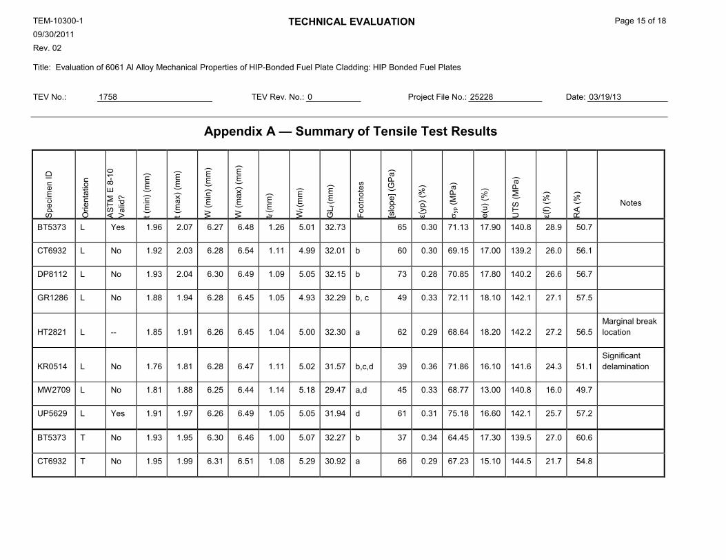
Appendix A — Summary of Tensile Test Results
Spe
cim
en ID
Orie
ntat
ion
AS
TM E
8-1
0 V
alid
?
t (m
in) (
mm
)
t (m
ax) (
mm
)
W (m
in) (
mm
)
W (m
ax) (
mm
)
t f (m
m)
Wf (
mm
)
GL f
(mm
)
Foot
note
s
[slo
pe] (
GP
a)
ε(yp
) (%
)
σ yp (
MP
a)
e(u)
(%)
UTS
(MP
a)
ε(f)
(%)
RA
(%)
Notes
BT5373 L Yes 1.96 2.07 6.27 6.48 1.26 5.01 32.73
65 0.30 71.13 17.90 140.8 28.9 50.7
CT6932 L No 1.92 2.03 6.28 6.54 1.11 4.99 32.01 b 60 0.30 69.15 17.00 139.2 26.0 56.1
DP8112 L No 1.93 2.04 6.30 6.49 1.09 5.05 32.15 b 73 0.28 70.85 17.80 140.2 26.6 56.7
GR1286 L No 1.88 1.94 6.28 6.45 1.05 4.93 32.29 b, c 49 0.33 72.11 18.10 142.1 27.1 57.5
HT2821 L -- 1.85 1.91 6.26 6.45 1.04 5.00 32.30 a 62 0.29 68.64 18.20 142.2 27.2 56.5 Marginal break location
KR0514 L No 1.76 1.81 6.28 6.47 1.11 5.02 31.57 b,c,d 39 0.36 71.86 16.10 141.6 24.3 51.1 Significant delamination
MW2709 L No 1.81 1.88 6.25 6.44 1.14 5.18 29.47 a,d 45 0.33 68.77 13.00 140.8 16.0 49.7
UP5629 L Yes 1.91 1.97 6.26 6.49 1.05 5.05 31.94 d 61 0.31 75.18 16.60 142.1 25.7 57.2
BT5373 T No 1.93 1.95 6.30 6.46 1.00 5.07 32.27 b 37 0.34 64.45 17.30 139.5 27.0 60.6
CT6932 T No 1.95 1.99 6.31 6.51 1.08 5.29 30.92 a 66 0.29 67.23 15.10 144.5 21.7 54.8
TEM-10300-1 09/30/2011 Rev. 02
TECHNICAL EVALUATION Page 16 of 18
Title: Evaluation of 6061 Al Alloy Mechanical Properties of HIP-Bonded Fuel Plate Cladding: HIP Bonded Fuel Plates
TEV No.: 1758 TEV Rev. No.: 0 Project File No.: 25228 Date: 03/19/13
Spe
cim
en ID
Orie
ntat
ion
AS
TM E
8-1
0 V
alid
?
t (m
in) (
mm
)
t (m
ax) (
mm
)
W (m
in) (
mm
)
W (m
ax) (
mm
)
t f (m
m)
Wf (
mm
)
GL f
(mm
)
Foot
note
s
[slo
pe] (
GP
a)
ε(yp
) (%
)
σ yp (
MP
a)
e(u)
(%)
UTS
(MP
a)
ε(f)
(%)
RA
(%)
Notes
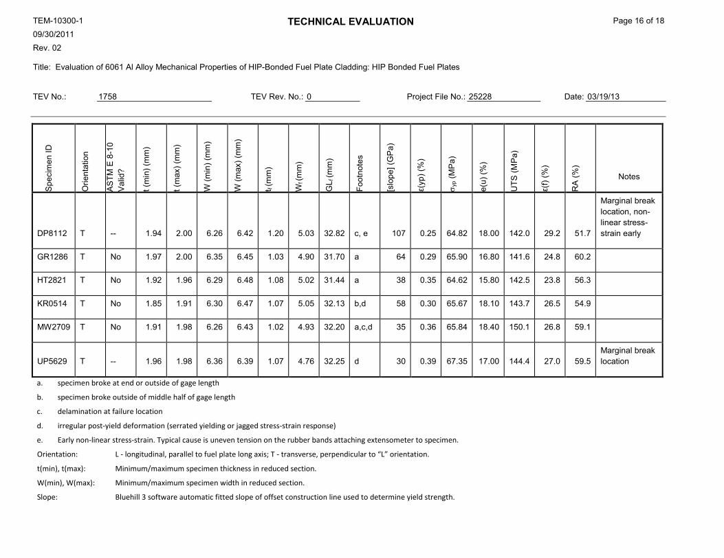
DP8112 T -- 1.94 2.00 6.26 6.42 1.20 5.03 32.82 c, e 107 0.25 64.82 18.00 142.0 29.2 51.7
Marginal break location, non-linear stress-strain early
GR1286 T No 1.97 2.00 6.35 6.45 1.03 4.90 31.70 a 64 0.29 65.90 16.80 141.6 24.8 60.2
HT2821 T No 1.92 1.96 6.29 6.48 1.08 5.02 31.44 a 38 0.35 64.62 15.80 142.5 23.8 56.3
KR0514 T No 1.85 1.91 6.30 6.47 1.07 5.05 32.13 b,d 58 0.30 65.67 18.10 143.7 26.5 54.9
MW2709 T No 1.91 1.98 6.26 6.43 1.02 4.93 32.20 a,c,d 35 0.36 65.84 18.40 150.1 26.8 59.1
UP5629 T -- 1.96 1.98 6.36 6.39 1.07 4.76 32.25 d 30 0.39 67.35 17.00 144.4 27.0 59.5 Marginal break location
a. specimen broke at end or outside of gage length
b. specimen broke outside of middle half of gage length
c. delamination at failure location
d. irregular post-yield deformation (serrated yielding or jagged stress-strain response)
e. Early non-linear stress-strain. Typical cause is uneven tension on the rubber bands attaching extensometer to specimen.
Orientation: L - longitudinal, parallel to fuel plate long axis; T - transverse, perpendicular to “L” orientation.
t(min), t(max): Minimum/maximum specimen thickness in reduced section.
W(min), W(max): Minimum/maximum specimen width in reduced section.
Slope: Bluehill 3 software automatic fitted slope of offset construction line used to determine yield strength.
TEM-10300-1 09/30/2011 Rev. 02
TECHNICAL EVALUATION Page 17 of 18
Title: Evaluation of 6061 Al Alloy Mechanical Properties of HIP-Bonded Fuel Plate Cladding: HIP Bonded Fuel Plates
TEV No.: 1758 TEV Rev. No.: 0 Project File No.: 25228 Date: 03/19/13
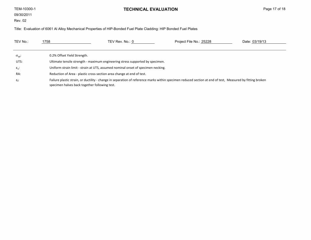
σyp: 0.2% Offset Yield Strength.
UTS: Ultimate tensile strength - maximum engineering stress supported by specimen.
εu: Uniform strain limit - strain at UTS, assumed nominal onset of specimen necking.
RA: Reduction of Area - plastic cross-section area change at end of test.
εf: Failure plastic strain, or ductility - change in separation of reference marks within specimen reduced section at end of test, Measured by fitting broken specimen halves back together following test.
TEM-10300-1 09/30/2011 Rev. 02
TECHNICAL EVALUATION Page 18 of 18
Title: Evaluation of 6061 Al Alloy Mechanical Properties of HIP-Bonded Fuel Plate Cladding: HIP Bonded Fuel Plates
TEV No.: 1758 TEV Rev. No.: 0 Project File No.: 25228 Date: 03/19/13
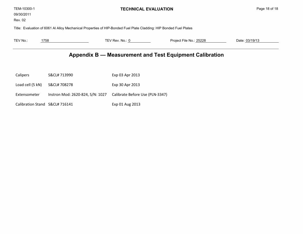
Appendix B — Measurement and Test Equipment Calibration
Calipers S&CL# 713990 Exp 03 Apr 2013
Load cell (5 kN) S&CL# 708278 Exp 30 Apr 2013
Extensometer Instron Mod: 2620-824, S/N: 1027 Calibrate Before Use (PLN-3347)
Calibration Stand S&CL# 716141 Exp 01 Aug 2013