Embed Size (px)
Citation preview

INSTRUMENTS AND NETWORKS
Allowable vapor control valvepressure dropsUnderstand the relationship between the pressure dropand the process system
F. YU, Jacobs Engineering Group, Houston, Texas
I n a previous article, the author stated the advantage of sizingcontrol valves using the minimum allowahle control valvepressure drop at maximum flow over other methods.' In this
article, more information is provided about the relationshipbetween the allowable control valve pressure drop and the pro-cess system it serves. Only vapor control valve allowable pressuredrop is discussed.
From an engineering design viewpoint, we want to select acontrol valve that is able to regulate the process fluid over a desiredflow range, a smaller valve control valve to reduce capital cost andless control valve pressure drop to reduce operating cost.
The control valve is part of a process system. Its function isto regulate process flow so that certain process conditions canbe maintained. A process system consists of source and destina-tion ec]uipment, wich a process line to move process fluid fromthe source to the destination. In the process line, there are otherprocess equipment, instruments, valves and fittings to processthe process fluid. Process variables in a process system are inlet/outlet temperatures and pressures, flowrate, line size, and controlvalve and system pressure drops. In this article, system pressuredrop is deflned as the total pressure drop of process equipment,instruments and line excluding the control valve pressure drop ina process system. The static head diflerence in a vapor system issmall and can be ignored. Increase the flowrate and the availahlepressure drop for a control valve and system will be reduced andvice versa.
If the process system has a compressor, it will be the sourceequipment. Usually it is a centrifugal compressor, and the systempressure will be affected by its performance curve. A centrifugalcompressor will generate lower head or lower system inlet pres-sure at high flow, and higher head or higher system inlet pressureat low flow.
In most cases, the process engineer will supply tiie allowablevapor control valve pressure drop for the instrument engineerto size and select the control valve. Process engineers sometimesspecify the allowable control valve pressure drop at maximum,normal and minimum process flowrates, but sometimes onlyprovide it at normal flowrate {since it is readily available from ahydraulic calculation).
Basis . The most common control valves used in industry areglobe and rotary (butterfly or ball). A globe control valve is usuallysmaller than a rotary control valve. The division between thesetwo types of control valves is 6 in. to 8 in. The strategy of select-
ing a ball or hutterfly rotary control valve is to select the ball typefirst since it has a wider operating range. Then, select the butterflyrotary control valve for higher flow applications.
The acceptable operating range of each control valve type var-ies among the professionals. In general, the acceptable operatingrange for a globe control valve is 20% to 90% open. The accept-able operating range for a ball rotary control valve is 15° to 90"open. The acceptable operating range for a butterfly rotary controlvalve is 15° to 60° open.
In this article, it is assumed that the acceptable globe controlvalve operating range is 20% to 90% open, and the acceptablerotary control valve operating range is 20° to 90" open. Further-more, it is assumed that the piping geometry factor is ignored.
Basic e q u a t i o n s . Each process system is designed to handleprocess fluid over a maximum to minimum flow range, withnormal flow between these two extremes. The process engineer'sjob is to carry out a hydraulic calculation for the process systembased on normal flow to flnd out its pressure profile and allowablecontrol valve pressure drop. Besides the system hydraulic calcula-tion, another source of allowable control valve pressure drop isfrom the compressor hydraulic calculation, which is usually basedon rated flow.
Control valve size usually depends on the maximum flow andthe allowable control valve pressure drop. A smaller allowablecontrol valve pressure will result in a larger control valve. In mostcases, it is justified to have a larger control valve with a smallerpressure drop, since the higher control valve cost can be recoveredby the reduced operating cost.^ If we assign a small allowablevapor control valve pressure drop, DP^, at maximum processflow rate, Q^, allowable control valve pressure drop at normal andminimum flow can be calculated as:
DP =DP + DP DP. x = \,2 (1)
where DP^^, is system pressure drop at maximum flow and DP^ iscontrol valve pressure drop at normal flow, (Q,, x = I), or mini-mum flow, {Qi' ^ = 2)- The system pressure drop in this studyis the sum of all the line, equipment and instrument pressuredrops that vary with flow. DP/, is the compressor head or pressureincrease at normal or minimum flow over the maximum flow. Eq.1 is a general equation, applicable to any process system.
Since in most cases, system pressure drop at normal flow, DP^i,is calculated, system pressure drop at maximum flow, DP^, can be
HYDROCARBON PROCESSING MARCH 2008 59

SPECIALREPORT INSTRUMENTS AND NETWORKS
estimated by the following equation:
(2)
For a vapor control valve, control valve CV^ at maximum pro-cess flow or CV^ at another flow can be calculated by the following
equations:
CV =
CV =
G r\zg
\}
= \,2
(3a)
(3b)
where 7*1 is control valve inlet pressure in psia, 71 is control valveinlet temperature in R (Rankine), 6,, is the ratio of gas molecularweight to air and Z is the gas conipressibility factor. CV^ andCV^ are control valve CKat maximum and other flovt-rates, Q^In scfti.
X^ Is the ratio of control valve pressure drop (DP^, A: = 0,1,2) toPI, dimensionless. It is calculated by the following equation:
X^=DPjP\ ;f = 0,1,2 (3c)
Y^ is the expansion factor (ratio of flow coefllcient for a gas tothat for a liquid at the same Reynolds number), dimensioniess. Itis calculated by the following equation:
l-XY = ^̂ \— 0 19 {%A\
^k/1.4 (3e)
F(, is the ratio of specific heat ratio of gas, k, to chat of air, 1.4. XT^.is the pressure drop ratio factor for a control valve without attachedfittings. It is the pressure drop ratio required to provide critical orsonic flow dirough the valve when F/, = 1.0. Y^ is larger than 0.667when flow through the control valve is subsonic, and it is 0.667 whenflow through the control valve is sonic. XT^. varies with control valveopening ;md its value is given in the valve manufacturer's catalog.
By taking a ratio of Eqs. 3a and 3b, the following equationcan be obtained:
CVx_
cvQx Y ^
0
YX
DP0
DPX
0.5
(4)
From Eqs. 1 and 4, following equation can be obtained interms of Q y
DP^
DP0
DP
X
CV
CVX
DP
DPo
,0.5
-~ (5)
Qo' ^^o' ^^so' y<i ^"li CVg (at maximum flowrate) are knownsince they are used to select a control valve. Once a control valve isselected, its CV^ at any other control valve opening can be foundfrom a control valve catalog. Flow at this control valve opening,Q .̂, can be calculated by iteration using Eqs. 5, 3c, 3d and 1.
A p p l i c a t i o n s . I he previous equations are used to study therelationship of allowable vapor control valve pressure drop and itsprocess system. To simplify the analysis, air at 60"F will be used as
the process fluid. Air pressure at the control valve inlet is 100 psig.Line size is chosen so that line pressure drop is about I psi/100 ftat maximum flowrate.
The process flow operating range is selected to be from 50%(minimum) to 110% (maximum) of normal flow. The allowablevapor control valve pressure drop is assigned based on maximumflow rate, Q,,- f'or each flow case, a control valve is selected usingthe manufacturer's control valve catalog.
Results of the study for globe control and rotary controlvalves are:
A. For a globe control valve, maximum air flowrates of 600,3,000, 150,000, 420,000 and 840,000 scfh are selected, using 1in., 2 in., 4 in., 6 in. and 8in. lines respectively. Five system pres-sure drops (based on maximum flow) are selected: 5, 25, 50, 75and 100 psi for each flow case.
The following factors are studied:1. Allowable vapor control valve pressure drop. DP,,, at maxi-
mum flow, Q,:Allowable vapor control valve pressure drops of 5, 10 and 15
psi are selected. The control valve is selected close to the maximumacceptable valve opening (90% open) with an equal-percentagecharacteristic. Table 1 shows the results.
From Fable 1, we see that, in general, a larger globe controlvalve is required if the allowable control valve pressure drop issmaller. But sometimes the same control valve is selected for dif-ferent allowable control valve pressure drops (see the maximumflow = 3,000 scfli).
2. Control valve performance at different system pressuredrops, D/>,̂ :
This study is based on a control valve selected using an iillowablecontrol valve pressure drop of 5 psi at maximum air flow (Table 1).
y n o i w^ ,., Control valve selection at different controlvalve pressure drops
Maximum air flow =i 600 scfh
DPo. psi
5
10
15
i CV-calc
0.431
0.313
0.260
Maximum air flow
5
10
15
2.153
1.566
1.315
Maximum air flow
5
10
15
107.3
77.66
64.90
Maximum air flow
5
10
15
299.9
218.1
180.4
Maximum air flow
5
10
15
600.2
43S.4
359.8
Valveopening, %
69.8
60.0
87.3
= 3,000 scfh
8S.6
75.4
70.5
= 150,000 scfh
84.5
83.6
77.2
= 420,000 scfh
77.9
87.8
82.8
= 840,000 scfh
69.6
86.1
88.4
Selected valve
1 in., 0.25 in. port, three flutes, cv - 1.07
1 In., 0.25 in. poo, three flutes, cv = 1.07
1 in., 0,25 in. port, one flute, cv = 0.354
1 in., 0.375 in. port, c v - 3.07
1 in., 0.375 in, port, cv = 3.07
1 in., 0.375 in. port, cv = 3.07
3 in,, 3'/i(in. port, c v = 136.0
2.5 in., 2'A in. port, cv = 99.4
2.5 in., 2% in. port, cv = 99.4
6 in., 7 in. port, cv ^ 394.0
6 in., AVs in. port, cv = 274.0
4 in., 4% in. port, cv = 224.0
8 in,, 8 in. port, cv -818 .0
8 in., 8 in. port cv = 567.0
6 in., 7 in. port, cv = 394.0
60 MARCH 2008 HYDROCARBON PROCESSING

INSTRUMENTS AND NETWORKS SPECIALREPORT
At accqjtabte minimum and maximum control vake openings (20%and 90%), flow through the control valve in terms of percentageof normal (low is calculated for various system pressure drops (atEiiiiximum flow). Results are listed in Table 2 for maximum air flowsof 3,000, 150,000,420,000 and 840,000 scfh. Our target is that thecontrol valve is able to operate over 50 to 110% of normal flow.
From this table we see that the selected globe control valves areLible to operate over a 50% to 110% flow range, operating flowrange is 103% to 108% of normal flow for a system pressure dropof 5 psi and 95% to 79% of normal flow for a system pressure dropof 25 to 100 psi. The operating flow range reduces as the sy.stempressure is increased. For the 100 psi system pressure drop cases,flow ar 20% control valve opening is sonic, since V2 = 0.667,
3. Select control valve away from the acceptable maximumcontrol valve opening:
Table 2 control valves are selected close to the acceptable maxi-mum opening (90% open). Control valve performance selectedaway from the maximum opening is listed in Table 3.
Comparing the globe control valve performance to the cor-responding one in Table 2, it can be seen that a larger control valve
TABLE 2. Control valve performance at differentprocess system pressure drops
Maximum air f low = 3,000 scfh; use 1 in.cv (20% open) = 0.199, cv (90% open) =
5
25
50
75
100
i Percent f low Percent flowat 20% open at 90% open
14.0 116.7
21,9 112.1
26.0 111.2
27.1 110.8
30.6 (sonic) 110.6
Maximum air f low = 150,000 scfh; use 3cv (20% open) = 7.53, cv (90% open) =
5
25
50
75
100
10,7 116-1
16.8 111.9
20.1 111,1
21.1 no.723.6 (sonic) 110.6
Maximum air flow = 420,000 scfh; use 6cv {20% open) = 25.8, cv (90% open) =
S
25
50
75
100
13.0 120,8
20.4 113.3
24.3 111.8
25.4 111,2
28.5 (sonic) 110.9
Maximum air flow ^ 840,000 scfh; use 8cv (20% open) - 58.1, cv (90% open) =
5
25
50
75
100
14,6 122,4
22.8 113.8
27.0 112.0
28.1 111.4
31.9 (sonic) 111.1
, 0.375 in. port valve, cv = 3.07;2.43
Flow range, %1
102,6
90,2
85.2
83.7
80,0
Covered50-110% flow
Yes
Yes
Yes
Yes
Yes
in., 3716 In. port valve, cv = 136;120
105,4
95.1
91.0
89.6
87.0
Yes
Yes
Yes
Yes
Yes
in., 7 in. port valve, cv = 394;368
107.8
92.9
87.5
85.8
82.4
Yes
Yes
Yes
Yes
Yes
in., 8 in. port valve, cv = 818;761
107.8
91.0
85.0
83.3
79.2
Yes
Yes
Yes
Yes
Yes
is selected if valve selection is away from the maximum acceptableopening (higher capital cost). Comparing the operating ranges ofTable 3 conurol valves to those in Table 2, Table 3 control valves arenot able to operate at the minimum flow (50% of normal flow)for a system with a larger system pressure drop (25 or 50 to 100psi) since at 50% of normal flow, control valve opening will be lessthan the acceptable lower limit, 20% open. Separate calculationsfor 150,000 scfh and 420,000 scfh show that if the control valve isselected at 66% and 73% opening, selected control valve-s (4 in., cv= 224; 8 in., cv =567) are still able to operate over the whole flowrange. Table 3 control valve operating flow range is larger than Tiible2 control valve operating flow range only for a system pressure dropof5psi (108%vs 103%, 3,000 scfli), (114% v-s 105%, 150,000scfh), (116% vs 108%, 420,000 scfli), and is smaller for the rest ofthe system pressure drop cases (for 25 psi /)/*,„, 58% vs 90%, 3,000scfli), (66% vs 95%, 150,000 scfh), (75% vs 93%, 420,000 scfh);(for 100 psi DP^, 33% vs 80%. 3,000 scfli), (42% vs 87%, 150,000scfH), (55% vs 82%, 420,000 scfli case).
4. Effect of higher maximum flow limit (wider flow range):Table 1 control valve selection is based on maximum flow
being 110% of normal flow. In this section we will study the con-trol valve selection based on higher maximum flows: 120% and150% of normal flow (system with wider flow range). The resultsare shown in Tables 4a and 4b. Maximum flow and maximumsystem pressure drop are increased proportionally to have a fliircomparison.
Table 4a shows that when increasing maximum flow from110% to 120% of normal flow, the same size globe control valvesare selected.
TABLE 3. Select control valve away from theacceptable maximum control valve opening (90% open)
Note: The 1-tn valve is selected hased on maximum flow with c<f= 2.153 and 85.6% waiveopening. The 3-in. valve is selected based on maximum flow with cv - 107.3 and 84.5% valveopening. The 6-in, valve is selected based on maximum flow with cv = 299.9 and 77.9% valveopening. The 8-in vatve is selected based on maximum How with cv = 500,2 and 59,6% vaiveopening. DPo = ^ pst.
Maximum air f low = 3,000 scfh; use 1 in.cv (20% open) = 0.622, cv (90% open) =
DPjo, psi
5
25
50
75
100
Percent f low Percent f lowat 20% open at 90% open
42.4 150.7
61.4 > 50 119.7
71.3>50 115.0
76.4 > 50 113.4
79.4 > 50 112.5
Maximum air f low = 150,000 scfh; use 6cv (20% open) - 25.8, cv (90% open) =
5
25
50
75
100
35,7 149.6
53.3 > 50 119.5
62.8 > 50 114.9
67.7 > 50 113.3
70.3 > 50 112.5
Maximum air f low = 420,000 scfh; use 8cv (20% open) ^ 58.1, cv (90% open) =
25
50
75
100
28.9 145.0
43.9 118.7
51.8 > 50 114.5
55.3 > 50 113.0
57.2 (sonic)> 50 112.3
, 0.75 in. port valve, cv = 8.84;8.17
Flow range, %
108.3
58.3
43.7
37.0
33.1
Covered50-110% flow
Yes
No
No
No
No
in., 7 in. port valve, cv = 394;368
113.9
66.2
52.1
45.6
42.2
Yes
No
No
No
No
in., 8 in. port valve, cv = 818;761
116.1
74.8
62.7
57.7
55.1
Yes
Yes
No
No
No
Note: The 1-in. valve is selected based on maximum llow with cv = 2.155 and 49.8% valveopening. The 6-in. valve is selected based on maximum flow wilh cv = 107.3 and 50,6% valveopening The 8-in. valve is selected based on maximum flow wiih cv = 300.9 and 49,5% valveopening. DPo= B psi,
HYDROCARBON PROCESSING MARCH 2008 61

SPECIALREPORT INSTRUMENTS AND NETWORKS
Flow, gpm
F I C - 1 A centrifugal compressor curve shows compressor headvariation with f lovtf.
Table 4b shows that when increasing maximum flow from1 10% to 150% of normal flow, larger globe control valves arerequired, the .selected control valve for 204,546 scfli is able tooperate at the minimum flow limit (50% of normal flow), butfor 4,091 scfli and 572,727 scfh, the selected control valves arenot able to operate at mininuim flow for a system with a largerpressure drop (> 139.5 psi or > 186 psi). An option to avoid thisproblem is to use a second smaller control valve for the low-flow service. Separate calculation shows that increasing allowablecontrol valve pressure drop docs not improve the flow limitationat minimum flow at 20% valve opening by selecting differentcontrol valves.
TABLE 4 a , Control valve performance—valve selectedbased on maximum flow at 120% of normal flow
Maximum air ftow = 3,273 scfh; use 1 in., 0,375 in. port valve, cv = 3.07;cv (20% open) = 0.199, cv (90% oper)) = 2.43
0P,o, psi
6.0
29.8
59.5
89.3
119.0
Percent flow Percent flowat 20% open at 90% open
14,6 122,0
23.1 120.6
26.7 120.3
29.3 (sonic) 120.2
33.3 (sonic) 120.2
Flow range, %
107.4
97.5
93.6
90.9
86.9
Covered50-120% flow
Yes
Yes
Yes
Yes
Yes
Maximum air flow = 163,636 scfh; use 3 in., 3%* in. port valve, cv = 136-cv (20% open) = 7,53. cv (90% open) = 120
6.0
29.8
59.5
89.3
119.0
11.1 121.4
17.7 120.4
20.7 120.2
22.5 (sonic) 120.2
25.6 (sonic) 120.1
Maximum air flow = 458,182 scfh; use 6 in.cv (20% open) = 25.8, cv (90% open) =368
6.0
29.8
59.5
89.3
119.0
13.6 126.4
21.5 121.9
25.0 121.0
27.2 (sonic) 120.7
31.0 (sonic) 120,5
110.3
102.7
99.5
97.7
94.5
Yes
Yes
Yes
Yes
Yes
, 7 in. port valve, cv = 394;
112.8
110.4
96.0
93.5
89.5
Yes
Yes
Yes
Yes
Yes
5. Effect of compre,ssor head variation with flow:A centrifugal compressor curve shows compressor head varia-
tion with flow (Fig. 1). The shape of the compressor curve dependson compression ratio, speed, type of gas and compressor design.In general, compressor head or discharge pressure will increasewhen Howrate i.s decreased, or it will decrease when flowrate isincreased. The amount of head increase or decrease depends onthe compressor curve and the operating point.
Since the control valve is selected based on maximum flowrateand a valve opening close to 90% open, compressor head willincrease for 20% control valve opening and decrease for 90%control vaive opening. The effects of compressor head increasesof 5 psi and 10 psi at 20% control vaive opening and compressorhead decreases of 5 and 10 psi at 90% control valve opening arelisted in Table 5.
From these tables we see the efl"ect of a compressor head increaseon the globe control valve performance at 20% valve opening (thelowest acceptable opening). As the compressor head increased (5psi or 10 psi), flow also increased, but slightly. The increase is about3.2% to 0.1 % {based on normal flow) for a 5 psi compressor headincrease and 5.9% to 0.1 % for a 10 psi compressor head increaseat different maximum system pressure drops. The largest increaseoccurred for the system with the smallest system pressure drop {5psi). Also shown is the eflect of a compressor head decrease on theglobe control valve performance at 90% valve opening (the highestacceptable opening). For a 5 psi compressor haid decrease, percentflow (based on normal flow) decrease is about 35.8 to 0.3. For a 10psi compressor head decrease, percent flow decrease is about 120.8to 0.3. The largest decrease again occurred for the system with the
TABLE 4 b , Control valve performance—valve selectedbased on maximum flow at 150% of normal flow
Note: The 1-in, valve is selected based on maximum flow with cv = 2.347 and 88 7% wiveopening. The 3-in, valve is selected based on maxiinum flow vtnth ci- = 117 1 and 88 7% valveopening. The 6-in. valve is selected based on maximum flow with cv = 327 1 and %2 1 % valveopening. Dp^ = 5 psi.
Maxinnum air f low = 4,091cv (20% open) ^0.319, cv
DPso. psi
9.3
46.5
93.0
139.5
186,0
Percent f lowat 20% open
26.2
40.5
47.0 (sonic)
55.7 (sonic)>50%
62,7 (sonic)>50%
scfh; use 1 in., 0,(90% open) = 4,
5 in. port valve, cv = 4,91;17
Percent f low Flow range, %at 90% open
165.7
153.9
152.0
151.4
151.0
Maximum air f low ^ 204,546 scfh; use 4 in.,cv (20% open) = 11.6, cv (90% open) = 205
9.3
46.5
93.0
139.5
186,0
19.1
29.8
34.9 (sonic)
41.9 (sonic)
47.5 (sonic)
165.1
153.8
152.0
151.3
151.0
Maximum air f low = 572,727 scfh; use 8 in.,cv (20% open) = 38, cv (90% open) = 476
9.3
46.5
93.0
139.5
186.0
22,3
34.3
40.5 (sonic)
48.3 (sonic)
54.7 (sonic)>50%
157.5
152.0
151.0
150.7
150.5
139.5
113.4
105.0
95.7
88.3
Covered50-150% flow
Yes
Yes
Yes
No
No
4% in. port valve, cv = 224;
146.0
124.0
117.1
109.4
103.5
Yes
Yes
Yes
Yes
Yes
8 in. port valve, cv = 567;
135.2
117.7
110.5
102.4
95.8
Yes
Yes
Yes
Yes
No
NotarThe 1-in valve is selected based on maximum flow with cv= 2 933 and 79 3% valveopening. The 4-in, valve ts selected based on maximum flow with cv = 146 2 and 74 6% valveopening. The B-irt. waive is selected based on maximum flow with cv = 410 4 and 83 8% valveopening. 0?^ = 5 psi.
MARCH 2008 HYDROCARBON PROCESSING

INSTRUMENTS AND NETWORKS
smallest systetn pressure drop. This table also show.s that selectedglobe control valves arc able to operate at a lower flow limit (50%of normal flow). Since selected control valves are ba.sed on the upperflow limit, they are able to operate over the whole flow range. At theacceptable tnaximum valve opening (90% open), cbe selected globecontrol valves may not be able to operate at the upper flow limitdue to a compressor head decrease; especially for a smaller controlvalve and system with a smaller system pressure drop ( <25 psl), orlarger compressor head decrease (>10 psi).
Flow also increased slightly for a system with 50 psi or less systempressure drop. Tbe increase is about .3.2 to 0.1 % (based on normalflow) for a 5 psi aimpressor head increase and 5.9 to 0.1 % for a 10psi conipres.sor head increase. The largest increase occtirred for tbesystem witb the smallest system presstire drop (5 psi). Also shown isthe effect of a compressor head decrease on die globe control valveperformance at 90% valve opening (the highest acceptable open-ing). For a 5 psi compressor head decrease, percent flow (based onnormal flow) decrease is about 35.8 lo 0.3. For a 10 psi compressorhead decrease, percent flow decrease is about 120.8 to 0.3. The larg-est decrease again occurred for the system with the smallest systempressure drop. This table also shows that the selected globe controlvalves are able to operate at a lower flow limit (50% of normal flow).Since tbe selected control valves are based on the upper flow limit,they are able to operate over the whole flow range. At tbe acceptablemaximum valve opening (90% open), tbe selected globe controlvalves may not be able to operate at the upper flow limit due to acompressor head decrease; especially for a smaller control valve and,system with a smaller .system pressure drop (<25 psi), or compressorhead decrease larger than 5 psi.
R, For rotary control valves, maximum air flowrates of420.000, 2,500,000 and 8,500,000 scfh are selected using 6 in.,12 in. and 20 in. lines respectively. Five system pressure drops(based on maximum flow) are selected: 5, 25, 50, 75 and 100 psifor each flow case.
Tbe following factors are studied:
TABLE 5. Effect of compressor head variation withflow—increase compressor head at 20% opening,decrease compressor head at 90% opening
Maximum air flow = 3,000 scfh; use 1 incv (20% open) = 0.199, cv (90% open) =
DP,^ psi
5
25
50
75
100
Percent flowat 20% open,
increase5 psi head
17.2
22.3
26.1
27.2
30,7 (sonic)
Percent flowat 90% open,
decreaseS psi head
82.0 < 110
110,2
110.6
110.5
no.5
Maximum air flow = 420,000 scfh; use 6cv (20% open) = 25.8, cv (90% open) =
5
25
50
75
100
16,0
20.7
24.4
25.5
28.6 (sonic)
85,0 < 110
ni.4111.3
111.0
110.8
., 0.375 in. port valve, cv = 3.07;:2.43
Percent flowat 20% open,
increase10 psi head
19.9
22.6
26.2
27.2
30.7 (sonic)
Percent flowat 90% open,
decrease10 psi head
0.0 < 110
108,2 < 110
110.1
110.3
110.3
in., 7 in. port valve, cv = 394;368
18.4
21.1
24.5
25.5
28.6 (sonic)
0.0 < 110
109.4 < no
110.7
110.7
110.6
Note: The 1-in, valve ts selected based on maKimum flow with cv= 2,153 and 85,5% valveopening. The 6-in. valve is selected based on maximum flow wllh cv - 300,0 and 76.9% valveopening. DP^ = 5 psi.
for demanding applications
Introducing the Series3000 XPIS-advancedgas detection for twowire systems.
The Series 30CX) XPIS is thelatest addition to HoneywellAnalytics' line of fixed
and portable products that monitor for toxic andexplosive gases. Adding 2-wire capability to theindustry's most complete range of gas detectors.the Series 3CXX) XPiS offers toxic gas detection andoxygen monitoring combined with easy operation inexisting two-wire systems. Smart sensors are pre-calibrated arwd configured for immediate use—justplug in the sensor and go, Hot-swapp^te,intrinsically safe sensor exchange eliminatesdowntime—no need for hot work permits. Remotemounting up to 15nV50 ft, expands area coverage,Rameproaf housing and ATEX. UL and CSA certifiedfor use in hazardoLE aBas, Ortioard diagrx3sticsand digital display pfovides valuable operational/troubleshooting infonnation. Honeywell Analytics.Experts in gas detection.
Honeywell
To learn more, or to obtain a free copy of Gas Book,our 84-page guide to gas detection, call 1 -800-538-0363,
visit www.honeywellanalytics.com oremail [email protected]
O CfflW HiiF"-yv/i.'N I
Select 160 at www.HydrocarbonProcessing.com/RS
SPECIALREPORT INSTRUMENTS AND NETWORKS
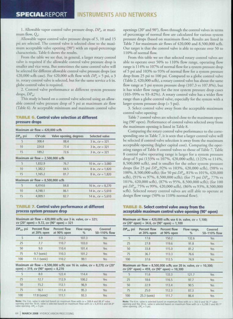
1. Allowable vapor control valve pressure drop, DP„, at maxi-mum flow, Qw-
Allowable vapor control valve pressure drops of 5, 10 and 15psl are selecred. The control valve is selected close to the maxi-mum acceptable valve opening (90°) with an equal-percentagecharacteristic. Table 6 shows the results.
From the tahle we see that, in general, a larger rotary controlvalve is required if the allowable control valve pressure drop issmaller and vice versa. But sometimes the same control valve willbe selected for different allowahle control valve pressure drops (.see420,000 scfh case). For 420,000 scfh flow with Z)P, = 5 psi, a 3in. rotary control valve is selected, but for the same service a 6 in.globe control valve is required.
1. Control valve performance at different system pressuredrops, DP,,,:
This study is based on a control valve selected using an allow-able control valve pressure drop of 5 psi at maximum air flow(Table 6). At acceptable minimum and maximum control valve
'•^-' -•• Control valve selection at differentpressure drops
Maximum air flow - 420,000 scfh
DP^psi
5
10
15
Maximum
5
10
15
CV-calc
308.4
224.8
189.2
air flow = 2,
1,832.9
1,382.2
1,165,2
Maximum air flow = 8,
S
10
15
6,414.6
4.748.1
4,009.1
Valve opening, degrees
88.4
77.4
72.6
500,000 scfh
76.7
84.5
81.7
500,000 scfh
84.8
86.1
82.7
Selected valve
3 in., cv = 321
3 in., cv = 321
3 in., cv = 321
10 in., cv = 3,000
8in.,cv = l,820
8in. ,cv=l ,820
16 in., cv = 8,270
14 in., cv = 5,610
14 in., cv = 5,610
TAB" Control valve performance at differentprocess system pressure drop
Maximum air flow = 420,000 scfh; use 3 in. valve, cv = 321;cv (20" open) = 9.72, cv {90° open) = 321
DP,o. psi
5
25
50
75
100
i Percent flowat 20% open
4.9
7.7
9.0
9.7 (sonic)
ll.Ksonic)
Percent flowat 90% open
112.2
110.7
110.4
110.3
110.2
Maximum air flow = 8,500,000 scfh; use 16open) = 319, cv (90° open) = 8,270
5
25
50
75
100
8.0
12.7
15.2
16.1
17.8 (sonic)
122.4
112.9
112.1
111.4
111.1
Flow range.
107.3
103.0
101.4
101.2
99.1
in. valve, cv
114.4
100.2
96,9
95.3
93.3
Covered50-110% flow
Yes
Yes
Yes
Yes
Yes
- 8,270; cv (20°
Yes
Yes
Yes
yes
Yes
openings (20° and 90"), flows through the control valves in termsof percentage of normal flow are calculated for various systempressure drops (based on maximum flow). Results are listed inTable 7 for maximum air flows of 420,000 and 8,'iOO.OOO scfh.Our target is that the control vaive is able to operate over 50 to1 10% of normal How.
From this table we see that selected rotary control valves areable to operate over 50% to 110% flow range, operating flowrange is 114% to 107% of normal flow for a system pressure dropof 5 psi and 103% to 93% of normal flow for a system pressuredrop from 25 psi to 100 psi. Compared to a globe control valve(Table 2, 420,000 scfh), a rotary control valve has about tbe .sameflow range at 5 psi system pressure drop (107.3 vs 107.8%), butit has wider flow range for the rest system pressure drop cases(10.^99% vs 93-82%). A rotary control valve has a wider flowrange than a globe control valve, especially for tbe system with alarger system pressure drop (> 5 psi).
3. Select control valve away from the acceptable maximumcontrol valve opening:
Table 7 control valves are selected close to the maximum open-ing (90° open). Performance of control valves selected away fromthe maximum opening is listed in Tahle 8.
Comparing the rotary control valve performance to the corre-sponding one in Tahle 7, it is seen that a larger control valve willhe selected if control valve selection is away from ilie maximumacceptable opening (higher capital cost). Comparing the oper-ating ranges of Table 8 control valves to those of Table 7, Tahie8 control valve operating range is larger for a system pressuredrop of 5 psi (133% vs 107%, 420.000 scfti), (122% vs 114%,8,500,000 scfh), and is smaller for the other system pressuredrops (for 25 psi DP,,,92% vs 103%, 420,000 .scfh), (98% vs100%, 8,500,000 scfli); (for 50 psi /)/>,„, 81% vs 101%, 420,000scfli), (91% vs 97%, 8,500,000 scfli); (for 75 psi DP^^, 77% vs101%, 420,000 scfh), (87% vs 95%, 8,500,000 scfh); (for 100psi DP,^, 75% vs 99%, 420,000 scfh), (86% vs 93%, 8,500,000scfh). Selected rotary control valves are still able to operate atdesign flow range (50% to i 10% normal flow).
Seiect control valve away from theacceptabie maximum control valve opening (90° open)
Maximum air flow = 420,000 scfh; use 6 in,cv (20° open) = 34,6, cv (90° open) = 1,100
5
25
50
75
100
)si Percent flowat 20% open
17,6
27.8
33.8
36.7
37.6
Percent flowat 90% open
150.2
119.6
115.0
113.3
112.5
valve, cv = 1,
Flow range,%
132,6
91.8
81.2
76.6
74.9
Maximum air flow = 8,500,000 scfh; use 20 in. valve, cv =cv (20° open) = 459, cv (90° open) = 10,300
5
25
50
75
100
11,6
18.6
22.9
25.0
25.3 (sonic)
133.3
116.5
113.4
112.3
111.7
121,7
97.7
90.5
87.3
86,4
100;
Covered50-110% flow
Yes
Yes
Yes
Yes
Yes
: 10,300;
Yes
Yes
Yes
Yes
Yes
Note: The 3-in, valve J5 selected based on manimum (low wilh cv - 308.4 and 88.4° vaiveopening and Ihe 16-in, valve is selected based on maximum flow wdh cv = 6.414.6 and 84.8°valve ofjeriing. DPj, = 5 psi
Note: Thp 6-in valve is selected based on maximum flow wilh cv = 302,0 and 55.7° valveopening and the 20-in. valvp is selected based on maximum flovif with cv = 6,298,3 and 80.1 °vatve opening, DP,, = 5 psi.
M MARCH 2008 HYDROCARBON PROCESSING

INSTRUMENTS AND NETWORKS
4. Effect of higher maximum flow limit (wider flow range):Table 6 control valve selection i.s based on maximum flow as
110% of normal flow. In this section we will study control valveselection hased on higher maximum flows: 120% and 150%of normal flow (system witb a wider flow range). Tbe resultsarc sbown in Tables 9a and 9b. Maximum flow and maximumsystem pressure drop are increased proportionally to bave a taircomparison.
Table 9a sbows that wben increasing maximum flow from1 10% to 120% of normal flow, a larger control valve (4 in. vs 3in.) is selected for 420,000 scfh flow, but tbe same control valveis selected for 8,'>00,000 scfli flow.
Tahle 9b sbows that when incre^Lsing maximum flow from 110%lo 150% of normal flow, larger rotary control valves are required.
TABLE 9 a . Control valve performance—valve selectedbased on maximum flow at 120% of normal flow
Maximum air flow = 458,182 scfh; use 4 in. valve, cv = 596;cv (20° open) - 21,1. cv (90° open) = 596
6.0
29.8
59.5
89.3
119.0
Percent flowat 20% open
11.2
18.1
21.6
22.6
25.6 (sonic)
Percent flowat 90% open
145.1
126.5
123.4
122.3
121.7
Flow range,%
133.9
108.4
101.8
99.7
96.1
Maximum air flow = SJllJll scfh; use 16 in. valve, cvcv (20° open) = 319, cv {90° open) = 8,270
6.0
29.8
59.5
89.3
119.0
8.3
13.4
15.7
16,9 (sonic)
19.3 (sonic)
127,6
122.4
121.3
120.9
120.7
119,3
109.0
105.6
104.0
101.4
Covered50-120% flow
Yes
Yes
Yes
Yes
Yes
= 8,270;
Yes
Yes
Yes
Yes
Yes
Note: The 4-in valve is sefecled based on maximum flow with cv = 533 and 73,8° valveopening and Ihe 16-in. valve is selected based on maximum flow witb cv = 7,073 and 86.7°valve opening, DPg = S psi.
TABLE 9 b . Control valve performance—valve selectedbased on maximum flow at 150% of normal flow
Maximum air flow = 572,727cv(20° open) = 21.1, cv {90"
9,3
46.5
93.0
139.5
186.0
scfti; use 4 inopen)= 596
isi Percent flow Percent flowat 20% open at 90% open
12,6
20.5
23.0 (sonic)
27.8 (sonic)
31.8 (sonic)
165,5
153.9
152.0
151.4
151.0
. valve, cv = 596;
Flow range.
152.9
133.4
129.0
123.6
119.2
Maximum air flow = 11,590,909 scfh; use 20 in. valve, cvcv (20° open) = 459, cv (90° open) - 10,300
9.3
46.5
93.0
139.5
186.0
13.7
22.6
25.7
29.8 (sonic)
34,1 (sonic)
158.6
152.3
151.2
150.8
150.6
144.9
129.7
125.5
121.0
116.5
Covered50-150% flow
Yes
Yes
Yes
Yes
Yes
= 10,300;
Yes
Yes
Yes
YesYes
Note: The 4-in valve 5 selected based on maximum flow with cv = 421 and 80.0% valveopenini) and the 20-in. valve \i, selected based on mammum flow with cv - 8.596 and 85 8%valve opening DPa = 5 psi
Select 161 at www.HydrocarbonProcessing.com/RS ••
S A M S O N
An all-round talentIn SAMSON'S Series 3730 Positioners,everything revolves around just one rotarypushbutton: turn to select parameters, pressto activate them. The large display is yourwindov^' to the system. Alternatively, youcan easily configure the positioner from aPC using the TROVIS-VIEW software.
The positioners are easy to integrate intoany loop of field devices over HART,PROFIBUS-PA or FOUNDATION Fieldbus.
Its range of functions is rounded off bylimit switches, position transmitters andsolenoid valves.
Definitely a turn for the better.
USA E-mail: samson@samson-osa,cominternet; http://www.somson-usa,com
Germany E-mail: samson@samson,deinterneh http://vrtvw.samson,de

INSTRUMENTS AND NETWORKS SPECIALREPORT
Selected rotary control valves are able to operate at minimum flow(50% of normal flow) for all the system pressure drops.
5. Effect of compressor head variation with flow;The effect of compressor head increases of 3 and 10 psi at 20"
valve opening and compressor head decreases of 5 and 10 psi at90° valve opening are listed in Table 10.
From these tables, we .see the effect of compressor head increaseon rotary control valve performance at 20" valve opening (the low-est acceptable openingj. As the compressor head increased (5 psior 10 psi), flow also increased, but slightly. The increase is about1.8% to 0% (based on normal flovi') for a 5 psi compressor headincrease and 2.0% to 0% tor a 10 psi compressor head increaseat different system pressure drops. The largest increase occurredfor the system with a 5 psi system pressure drop. Also shown isthe effect of a compressor head decrease on rotary control valveperformance at 90° valve opening (the highest acceptable open-ing). For a 5 psi compressor head decrease, percent flow (based onnormal flow) decrease is about 38.7 to 0.1. For a 10 psi compres-sor head decrease, percent flow decrease is about 122.4 to 0.3.The largest decrease occurred tor the system with a 5 psi syscempressure drop. This table shows that the selected rotary controlvalves are able to operate at the lower flow limit (30% of norma!flow). Since the selected control valves arc based on the uppermaximum flow limit, they are able to operate over the whole Rowrange. At the acceptable maximum valve opening (90" open), for420,000 scfli, the selected rotary control valve is able to operateat the maximum flow limit for the system with the larger systempressure drop (>75 psi) and smaller compressor head drop (3 psi).For 8,500,000 scfli, the selected rotary control valve is able tooperate at the maximum flow limit with a system pressure drop>23 psi and larger compressor head drop (10 psi). Therefore, alarger rotary control valve is less sensitive to compressor headdecrease at 90° opening.
Discussion.1. I he process engineer should provide allowable control valve
pressure drop at minimum, normal and maximum flows, so thatthe instrument engineer is able to select a proper control valvefor the full operating range. For a system without a compressor,often only system pressure drop at normal flow is available fromhydraulic study. But Fq. 2 can be used to estimate the systempressure drop at maximum flowrate. Then, allowable controlvalve pressure drops at maximum and minimum flowrates canbe estimated using Eq. 1. For a syscem with a compressor, oftenthe system pressure drop at maximum flow is available since thecompressor hydraulic calculation is based on maximum flow.
2. To minimize the operating cost, it is recommended to assigna minimum allowable pressure drop for thecontrol valve at maxi-mum t1ow. It is also recommended to size the control valve close tomaximum acceptable valve opening, since it will result in a smallercontrol valve (less capital cost) and wider flow range.
If there are several branches between the compressor and des-tination equipment, the previous rule should apply to the criticalbranch thar will result in a smallest compressor discharge pressure.
3. In general, a rotary control valve has a wider flow range(107-92% normal flow) than a globe control valve (93-82%normal flow) for a system pressure drop >5 psi. For a systempressure drop or3 psi, their flow range is about the same (107%vs 108%).
4. For a system with a wider flow range (30% to 150% ofnormal flow), a globe control valve sometimes is not able to
i n Effect of compressor head variationwith flow—increase compressor head at 20° opening,decrease compressor head at 90° opening
Maximum air f low = 420,000 scfh; use 3 incv (20° open) = 9.72, cv (90° open) = 321
DPjo, psi Percent flowat 20% open,
increase5 psi head
25
50
75
100
6-0
7.8
9.0
9.7 (sonic)
11.1 (sonic)
Percent flowat 90% open,
decrease5 psi head
78.3 c 110
108.7 < 110
109.9 < no
110.0
110,1
. valve, cv = 321;
Percent f lowat 20% open,
increase10 psi head
6.9
7.9
9.0
9.7 (sonic)
11.1 (sonic)
Maximum air flow = 8,500,000 scfh; use 16 in. valve, cv =cv (20° open) = 319. cv (90° open) = 8,270
5
25
50
75
100
9,8
12.9
15.3
16.1
17.8 (sonic)
83,7 < n o
111.7
111.5
111.2
110.9
11.3
13.1
15.4
16.117.8 (sonic)
Percent flowat 90% open,
decrease10 psi head
0<110
106.7 < 110
109.3 < 110
109.8 < 110
109.9 < 110
: 8,270;
o<no109.4 < no
110.9
110.9
110.8
Note: The 3-in. valve is selected based on mammum flow with cv = 308.4 and 88 4° valveopening and the 14-in. valve is selected based on maxtmum flow with cv = 6,41'1.6 and 84.8°valve opening. DP^ = 5 psi
cover the minimum flow, but the rotary control valves do nothave this problem.
5. In this study, selected globe control valves are able to turndown the How to 18 to 3 1 % of normal flow at 20% control valveopening, assuming the compressor head increase is 10 psi. Forselected rotary control valves at 20" opening and a 10 psi com-pressor head increase, flow can be turned down to 7 to 18% ofnormal flow.
Selected globe control valves are still able to pass 110% nor-mal flow at 90% control valve opening if system pressure drop isgreater than 25 psi. Selected rotary control valves at 90" openingare able to pass 110% normal flow if the control valve size is large(>3 in.), system pressure drop is large (>25 psi) and the compres-sor head decrease is less (<10 psi).
Since the control valve is selected based on maximum flowand close to acceptable maximum control valve opening, theselected control valve wili be guaranteed to be able to operate atmaximum flow.
6. The analysis in this study assumes that the hydraulic calcu-lation matches actual plant operation. Often, pressure drops ofequipment or instruments are over estimated in hydraulic calcula-tion. This will cause more pressure drop available for the controlvalve in real operation. HP
LITERATURE CITED' H C. Yu, "Easy way co estimate realistic contro! valve pressure drops,"
Hydrocarbon I'rocessing, August 2000, p. 45-48.' Control Valve Handhooii, 3rd edition. Fisher Conrrols International, Inc..
2001.
Frank C. Yu is a senior process engineer at Jacobs EngineeringGroup, Inc., Houston, Texas. He specializes in process design. Dr.Yu hold5 a BS degree from Tunghai University, an MS degree fromthe University of Massachusetts, and a PhD from the Universityof Texas at Austin, all in chemical engineering.
HYDROCARBON PROCESSING MARCH 2008 67