Embed Size (px)
Citation preview

Allison Lake Hydropower Development
FINAL FEASIBILITY STUDYADDENDUM
Allison Lake Hydropower DevelopmentAllison Lake Hydropower Development
FINAL FEASIBILITY STUDYFINAL FEASIBILITY STUDYADDENDUMADDENDUM
January 2011
CreekCreek

The Energy Company
Robert A. Wilkinson, CEO January 10, 2011 Copper Valley Electric Association H-327730 P.O. Box 45 Glennallen, AK 99588-2832 Dear Robert: Subject: Allison Creek Hydroelectric Project
Final Feasibility Study – Addendum
We are pleased to submit herewith our Addendum to the Final Feasibility Study (FFS) for the Allison Lake Hydroelectric Project. The FFS presented our analysis of six technically feasible arrangements for the project. This Addendum presents our analysis of two additional options for the project. Together these documents comprise the results of Hatch’s study of the feasibility for hydropower development of the Allison Creek basin.
Alternative 4a (Alt 4a): A run-of-river development on Allison Creek commencing approximately 2,000 downstream of the outlet of Allison Lake consisting of a diversion structure and a penstock leading to a 6.5 MW powerhouse at the same location as considered for Alt 3c.
Alternative 4b (Alt 4b): The addition of an inflatable gate on the Solomon Gulch Spillway that would raise the normal maximum water surface of Solomon Lake by five feet.
Our principal conclusions for these two alternatives as stated within the report include:
Alternative 4a - A run-of-river Alt 4a development of the Allison Creek basin is not cost effective with operation within
the Copper Valley Electric Association, Inc.’s (CVEA) existing system load. - With the addition of 2 MW to the CVEA system load, the project would be competitive with the cost of
diesel generation. - The reduced scale of the hydropower development of the Allison Creek basin as offered by Alt 4a would
reduce the risk of construction cost overruns, seepage and dam safety concerns and environmental impacts as compared to Alt 3c.
- Alt 4a is superior to Alt 3c in all respects.
Alternative 4b - The addition of inflatable gates to the Solomon Gulch Spillway as proposed for Alt 4b would add
approximately 2 GWh of energy to the CVEA system. - The addition of inflatable gates to the Solomon Gulch Spillway as proposed for Alt 4b would require
amendment to existing FERC License for the Solomon Gulch Project. - On the basis of the energy potential and cost estimates prepared for this evaluation, Alt 4b currently
would not be an economically viable project.
Based on these conclusions we recommend that the CVEA adopt Alt 4a as the preferred alternative for the development of the hydroelectric potential of the Allison Creek basin and that further consideration of Alt 3c and Alt 4b be terminated.
We greatly appreciate the opportunity to work with you on this interesting project. If you have any questions regarding the subject report, be sure to give us a call.
Yours very truly,
A. Richard Griffith, P.E. Project Manager
Hatch Acres Corporation6 Nickerson Street, Suite 101, Seattle, WA 98109 USA Tel: 206-352-5730 • Fax: 206-352-5734 • www.hatchusa.com

Copper Valley Electric Association, Inc. - Allison Lake Hydroelectric Project
Addendum – Final Feasibility Report
January 2011 Page i
Table of Contents
1. Introduction ............................................................................................................................................ 1 1.1 General.......................................................................................................................................... 1 1.2 Alternative 4 – General Arrangement ............................................................................................. 2 1.3 Alternative 4a – Diversion Structure on Allison Creek with Penstock leading to
Powerhouse (Alt 4a) ....................................................................................................................... 3 1.4 Alternative 4b – Raising Solomon Gulch Reservoir Maximum Water Surface 5 feet with
Inflatable Gates on Spillway (Alt 4b) .............................................................................................. 4
2. Power Studies.......................................................................................................................................... 6 2.1 Unconstrained Run-of-River Operation .......................................................................................... 6 2.2 System Loads and Resources .......................................................................................................... 7
2.2.1 System Loads........................................................................................................................ 7 2.2.2 System Resources ................................................................................................................. 7
2.3 AUTO Vista Model: Allison Creek Run-of-River Hydropower Development................................... 8 2.4 Hydrology...................................................................................................................................... 8 2.5 Hydro Equipment Characteristics ................................................................................................... 9 2.6 AUTO Vista Results........................................................................................................................ 9
3. Project Construction Cost and Construction Schedule.......................................................................... 13 3.1 Construction Cost Estimates ......................................................................................................... 13
3.1.1 Alternative 4a..................................................................................................................... 13 3.1.2 Alternative 4b..................................................................................................................... 14
3.2 Construction Schedule ................................................................................................................. 15 3.3 Economic Analysis ....................................................................................................................... 16
3.3.1 Cost of Power – Alternative 4a ........................................................................................... 17 3.3.2 Cost of Power – Alternative 4b........................................................................................... 18
4. Regulatory and Environmental Considerations...................................................................................... 20 4.1 Alternative 4a............................................................................................................................... 20
4.1.1 Regulatory Considerations.................................................................................................. 20 4.1.2 Environmental Field Investigations ..................................................................................... 21 4.1.3 Environmental Considerations ............................................................................................ 22
4.2 Alternative 4b .............................................................................................................................. 22 4.2.1 Regulatory Considerations.................................................................................................. 22 4.2.2 Environmental Field Studies ............................................................................................... 22 4.2.3 Environmental Considerations ............................................................................................ 23
5. Conclusions and Recommendations ...................................................................................................... 24 5.1 Conclusions ................................................................................................................................. 24
5.1.1 Alternative 4a..................................................................................................................... 24 5.1.2 Alternative 4b..................................................................................................................... 24
5.2 Recommendations ....................................................................................................................... 25
6. References............................................................................................................................................. 26

Copper Valley Electric Association, Inc. - Allison Lake Hydroelectric Project
Addendum – Final Feasibility Report
January 2011 Page ii
Tables Table 1.1 FFS – Design and Economic Conditions .................................................................................. 1 Table 2.1 AUTO Vista Hydrologic Years ................................................................................................ 9 Table 2.2 Annual Generation – Existing Condition, Loads and Resources ............................................ 10 Table 2.3 Annual Generation – Alt 4a w/ Existing Load........................................................................ 10 Table 2.4 Annual Generation – Alt 4b w/ Existing Load ....................................................................... 10 Table 2.5 Annual Generation – Existing Resources w/ 2 MW Additional Load ..................................... 11 Table 2.6 Annual Generation – Alt 4a w/ 2 MW Additional Load ........................................................ 11 Table 2.7 Annual Generation – Alt 4b w/ 2 MW Additional Load ........................................................ 11 Table 2.8 Annual Benefits – Alt 4a & 4b............................................................................................... 12 Table 3.1 Alternative 4a – Total Construction Cost (Bid 1/2010).......................................................... 14 Table 3.2 Alternative 4b – Total Construction Cost (Bid 1/2010) ......................................................... 15 Table 3.3 Basic Assumptions for Economic Analysis............................................................................. 16 Table 3.4 Alternative 4a – First Year Annual Cost (2010 Dollars)......................................................... 17 Table 3.5 Alternative 4a – Cost of Power ............................................................................................. 18 Table 3.6 Alternative 4b – Cost of Power............................................................................................. 19 Table 4.1 Summary of Major Environmental Field Studies ................................................................... 21
Figures Figure 1.1 Alternative 4 General Arrangement........................................................................................ 2 Figure 1.2 Alternative 4a – Plan and Profile ............................................................................................ 3 Figure 1.3 Diversion Structure – Plan and Cross Section......................................................................... 4 Figure 1.4 Typical Obermeyer Gate Installation...................................................................................... 5 Figure 1.5 Solomon Gulch Obermeyer Spillway Gate Cross Section ....................................................... 5 Figure 2.1 Allison Creek Annual Flow-Duration Curve ............................................................................ 6 Figure 2.2 Allison Average Monthly Distribution of Energy Production .................................................. 7 Figure 2.3 AUTO Vista Model Elements: Alts 4a and 4b.......................................................................... 8 Figure 2.4 Allison Powerhouse Unit Characteristics – 2 x 3.25 MW Units .............................................. 9 Figure 3.3 Alternative 4a – Construction Schedule................................................................................ 16
Appendices Appendix A – Alternative 4a, System Dispatch
Appendix B – Obermeyer Gate Cost Estimate

Copper Valley Electric Association, Inc. - Allison Lake Hydroelectric Project
Addendum – Final Feasibility Report
January 2011 Page 1
1. Introduction
1.1 General A fundamental premise of the studies leading to the Final Feasibility Study (FFS) for the Allison Lake Hydroelectric Project (Project) of May 2010 was that an additional hydropower project is needed to support the Solomon Gulch Project during winter months. Currently the Copper Valley Electric Association, Inc. (CVEA) must rely on diesel generation to meet system load to make up for the inability of the Solomon Gulch Project to generate during the winter period. The Allison Creek basin exhibits the same basic annual pattern of inflow as the Solomon Gulch basin. The 7 months of May through November are estimated to account for 98% of the annual inflow leaving only a 2% contribution for the 5 months of December through April. Accordingly, the focus of the FFS was to determine the most cost-effective manner to mobilize the potential storage capability of Allison Lake to allow for generation during the low-flow winter-time period. In all, six different schemes, Alt 1, Alt 2 and Alt 3a through Alt 3d, were reviewed and reported on as part of the previous studies for the Project. The manner in the proposed design for each alternative provides the necessary storage is described in Section 1.3 through Section 1.5 of the FFS.
The Project studies have shown that each of the six arrangements are technically and environmentally feasible. However, the studies also reveal that each arrangement includes significant challenges potentially affecting their long term economics and/or operational reliability as listed in Table 1.1.
Table 1.1 Final Feasibility Report Design and Economic Considerations
Alternative Design and Economic Considerations Alt 1 Tunnel cost Alt 2 Tunnel cost Alt 3a Reliable operation of siphon and maintenance thereof during winter period, access Alt 3b Drilling of micro-tunnel in glacial moraine Alt 3c Embankment cost, foundation conditions for embankment, seepage, liquefaction & avalanches, access Alt 3d Embankment cost, foundation conditions for embankment, seepage, liquefaction & avalanches, access
Subsequent to the completion of the FFS, the range of challenges as summarized above led to a concern regarding the viability of a storage project within the Allison Creek drainage. However, the high elevation of the first 2000’ below the outlet of Allison Lake suggests that there would be a significant amount of energy available from Allison Creek as a run-of-river project.
To date, the system load characteristics of CVEA has been such that much of this additional energy would be stranded; i.e. there would be no load available for the project to serve. Recently, however, a 2 MW industrial facility has been brought into the CVEA system. This additional load will provide an opportunity to CVEA to more fully operate a run-of-river project to accommodate what would otherwise be served by diesel generation.
The purpose of this Addendum to the FFS dated May 2010, is to present the evaluation of the economic viability of alternative run-of-river arrangements for capturing the hydropower potential of

Copper Valley Electric Association, Inc. - Allison Lake Hydroelectric Project
Addendum – Final Feasibility Report
January 2011 Page 2
Allison Creek as a project to serve an expanded CVEA system load. This scheme is referred to as Alt 4. The scope of work leading to this Addendum to the FFS has included the following activities:
1. Development of alternative project arrangements consistent with the purposes of this Addendum.
2. Review of Allison Lake hydrology as related to the run-of-river hydropower potential of the identified alternatives.
3. Preliminary layout and cost estimate of hydroelectric project features for each of the identified project arrangements.
4. Economic evaluation of the identified alternatives.
5. Environmental review of the of the identified alternatives.
6. Preparation of this addendum to the Final Feasibility Report including the resulting conclusions and recommendations.
1.2 Alternative 4 – General Arrangement The primary features of the run-of-river project selected for this review include the following:
• A low diversion structure on Allison Creek at El. 1300; • A 42” diameter surface / buried penstock;
• A 6.5 MW powerhouse along Allison Creek at El. 130 with a 1.75 mile transmission line leading to the Solomon Gulch switchyard; and
• A permanent 1,000 foot access road to the powerhouse and a temporary 4,500 foot trail for penstock construction access.
The general arrangement of these features for Alt 4 is shown in Figure 1.1. Two versions of Alt 4 are reviewed herein as described in the following paragraphs.
Figure 1.1 Alternative 4 General Arrangement
ALTERNATIVE 4
Diversion Structure
Powerhouse
Penstock
Allison Lake
ALTERNATIVE 4
Diversion Structure
Powerhouse
Penstock
Allison Lake

Copper Valley Electric Association, Inc. - Allison Lake Hydroelectric Project
Addendum – Final Feasibility Report
January 2011 Page 3
1.3 Alternative 4a – Diversion Structure on Allison Creek with Penstock leading to Powerhouse (Alt 4a)
Alt 4a includes the primary features as described above. Plan and profile views of Alt 4a are shown in Figure 1.2. The general details of the penstock and powerhouse are shown on Figures B.6 and B.7 respectively within Appendix B of the FFS. The actual dimensions of the penstock and powerhouse will be in proportion to the 42” penstock and 6.5 MW powerhouse as referenced above for Alt 4 in lieu of the 36” penstock and 4 MW powerhouse for Alt 3c as shown in the FFS.
The access road to the powerhouse as shown in Figure 1.2 will be designed in accordance with the criteria set forth in Appendix C.3 of the FFS. The design of the access trail from the loop road off the Trans Alaska Pipeline System corridor to the point where the penstock crosses over a ridge will follow the same alignment to that point as was studied for the construction access for Alt 3c. However, the width of the corridor will be reduced consistent with the use of helicopters as the primary access for construction of the penstock and diversion structure.
Figure 1.2 Alternative 4a – Plan and Profile
PLAN
PROFILE
The diversion structure will be located along Allison Creek at approximately El. 1300. The specific location and type of diversion scheme to be used for the run-of-river option will be determined at the next level of the design process. A conceptual drawing of the type of diversion structure used for the present purpose is shown in Figure 1.3.
Surface / Buried Penstock
0+00
5+00
10+0
0
15+0
0
20+0
0
25+0
0
30+0
0
35+0
0
40+0
0
45+0
0
50+0
0
55+0
0
60+0
0
65+0
0
100
500
1000
Elev
atio
n (f
t)
Station(ft)
Powerhouse70
+00
Surface / Buried Penstock
0+00
5+00
10+0
0
15+0
0
20+0
0
25+0
0
30+0
0
35+0
0
40+0
0
45+0
0
50+0
0
55+0
0
60+0
0
65+0
0
100
500
1000
Elev
atio
n (f
t)
Station(ft)
Powerhouse70
+00
Diversion Structure
Powerhouse
Surface / Buried Penstock
AccessTrail
AccessRoad
Allison Lake
Diversion Structure
Powerhouse
Surface / Buried Penstock
AccessTrail
AccessRoadAccessRoad
Allison Lake

Copper Valley Electric Association, Inc. - Allison Lake Hydroelectric Project
Addendum – Final Feasibility Report
January 2011 Page 4
Figure 1.3
Diversion Structure – Plan and Cross Section
PLAN
CROSS SECTION
1.4 Alternative 4b – Raising Solomon Gulch Reservoir Maximum Water Surface 5 feet with Inflatable Gates on Spillway (Alt 4b)
Alt 4b adds additional storage to the Solomon Gulch reservoir by modifying the spillway with 5 foot high inflatable gates extending the full length of the 450 foot long spillway. The proprietary Obermeyer Gate System, which consists of steel panels that are raised up by inflating a rubber bladder, has been selected for evaluation of Alt 4b on the basis that the rubber bladder gates without steel panels are not sufficiently controllable. They must be either in the fully inflated or fully deflated mode and can release too much water into the tailrace during the transition. The Obermeyer gates can operate at any stage between up or down thereby controlling water release. A typical Obermeyer gate installation and proposed profile view of Alt 4b are shown in Figure 1.4 and Figure 1.5, respectively.
1300
1310
1300
1310
0 10 20 5030 40
SCALE IN FEET
42”F
Pens
tock
Alli
son
Cre
ek
1300
1310
1300
1310
0 10 20 5030 40
SCALE IN FEET
0 10 20 5030 400 10 20 5030 40
SCALE IN FEET
42”F
Pens
tock
Alli
son
Cre
ekA
lliso
n C
reek
EL. 1300
EL. 1306
WS EL. 1301 @ 80 cfs
WS EL. 1305 @ 800 cfs
15 20100 5
SCALE IN FEET
EL. 1300
EL. 1306
WS EL. 1301 @ 80 cfs
WS EL. 1305 @ 800 cfsWS EL. 1305 @ 800 cfs
15 20100 5
SCALE IN FEET
15 20100 5 15 20100 5 15 20100 5
SCALE IN FEET
Copper Valley Electric Association, Inc. - Allison Lake Hydroelectric Project
Addendum – Final Feasibility Report
January 2011 Page 5
Figure 1.4 Typical Obermeyer Gate Installation
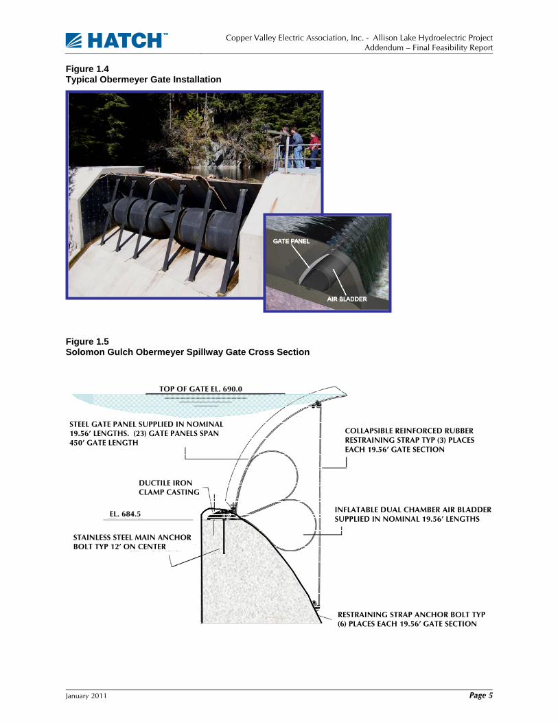
Figure 1.5 Solomon Gulch Obermeyer Spillway Gate Cross Section
COLLAPSIBLE REINFORCED RUBBER RESTRAINING STRAP TYP (3) PLACES EACH 19.56’ GATE SECTION
TOP OF GATE EL. 690.0
STEEL GATE PANEL SUPPLIED IN NOMINAL 19.56’ LENGTHS. (23) GATE PANELS SPAN 450’ GATE LENGTH
DUCTILE IRON CLAMP CASTING
EL. 684.5 INFLATABLE DUAL CHAMBER AIR BLADDER SUPPLIED IN NOMINAL 19.56’ LENGTHS
RESTRAINING STRAP ANCHOR BOLT TYP (6) PLACES EACH 19.56’ GATE SECTION
STAINLESS STEEL MAIN ANCHOR BOLT TYP 12’ ON CENTER

Copper Valley Electric Association, Inc. - Allison Lake Hydroelectric Project
Addendum – Final Feasibility Report
January 2011 Page 6
2. Power Studies
2.1 Unconstrained Run-of-River Operation By definition, without a reservoir to regulate available flows at the intake, a hydropower project can only be operated when instantaneous flows are within the range of physical capability of the generating equipment. All flows greater than the maximum hydraulic capacity of the equipment will flow past the intake as spill. In addition, all flows required for other instream uses as well as all flows less than that required to operate the smallest hydropower unit at the site must be passed by the intake.
This condition is illustrated in Figure 2.1 in the form of an annual flow duration curve for the run-of-river hydropower arrangement described in Section 1. The curve, which is based on the hydrology defined in the FFS, shows that a run-of-river facility installed on Allison Creek could operate whenever the flows in the creek are between 85 cfs and 9 cfs for the condition:
• The maximum turbine flow is 80 cfs; • The. minimum instream flow release is 5 cfs; and • The minimum turbine flow is 4 cfs.
Figure 2.1 Allison Creek Flow Annual Flow-Duration Curve
On this basis, the plant could operate approximately 62% of the time and the total amount of water available for generation, Qgen, is represented by the blue cross-hatched area within Figure 2.1. The difference in elevation between the diversion structure and the powerhouse times Qgen times 8,760 hours in a year provides an estimated 23.3 GWh as the average total amount of energy potentially available from a run-of-river project on Allison Creek.
0.0
50.0
100.0
150.0
200.0
0% 10% 20% 30% 40% 50% 60% 70% 80% 90% 100%
Excedence
Flow
(cf
s)
Instream FlowQmin=5 cfs
Unit Qmin=4 cfs
Generation 23.3 GWh(Unit Qmax=80 cfs)
Spill
Excedence
Flow
(cfs
)
0.0
50.0
100.0
150.0
200.0
0% 10% 20% 30% 40% 50% 60% 70% 80% 90% 100%
Excedence
Flow
(cf
s)
Instream FlowQmin=5 cfs
Unit Qmin=4 cfs
Generation 23.3 GWh(Unit Qmax=80 cfs)
Spill
Excedence
Flow
(cfs
)

Copper Valley Electric Association, Inc. - Allison Lake Hydroelectric Project
Addendum – Final Feasibility Report
January 2011 Page 7
The same basic approach as applied to monthly flow duration curves results in the monthly distribution of the 23.3 GWh as shown in Figure 2.2.
Figure 2.2 Allison Average Monthly Distribution of Energy Production
The above analysis is valid for the case that the energy from the Project is not constrained by system load conditions. Specifically, the monthly distribution of energy as shown in Figure 2.2 is important from the perspective of the ability of CVEA to assimilate energy from a run-of-river project on Allison Creek into their system. For example, the Solomon Gulch Project can substantially accommodate the total system under current load conditions for the month of July. Accordingly, the 4.8 GWh available generation from Allison Lake could theoretically be stranded and the Allison Creek flows would spill past the intake.
However, the complete loss of the 4.8 GWh will be offset to some degree by the storage capability within Solomon Gulch by allowing Solomon Gulch to remain full longer into the fall season. The analysis of this opportunity is with the AUTO Vista model as presented in the FFS is presented below for Alt 4a and Alt 4b.
2.2 System Loads and Resources
2.2.1 System Loads The AUTO Vista model operates on hourly intervals to meet system loads in the most cost effective manner using available system resources as a function of their respective cost of production. For the present study, two cases for the system load were considered as follows:
• The system load as recorded by CVEA data for 2006, as was the basis for all previous studies; and
• The above case with the addition of a new 2 MW load to continuously serve Petro Star for 50 weeks of the year.
2.2.2 System Resources The system resources considered for the existing case included the combined diesel plant facilities in Valdez and Glennallen, the combined cycle unit as operated under the contract with Petro Star, and the existing hydropower facilities at the Solomon Gulch Project. The proposed development
0.1 0.0 0.0 0.1
2.2
4.3
4.8
4.3
3.6
2.7
1.0
0.4
0.0
0.5
1.0
1.5
2.0
2.5
3.0
3.5
4.0
4.5
5.0
Jan Feb Mar Apr May Jun Jul Aug Sep Oct Nov Dec
Total Annual Energy = 23.3 GWh

Copper Valley Electric Association, Inc. - Allison Lake Hydroelectric Project
Addendum – Final Feasibility Report
January 2011 Page 8
included the additions as discussed in Section 1 as well as retirement of the existing thermal generation resources to the extent possible in each respective case under consideration.
2.3 AUTO Vista Model: Allison Creek Run-of-River Hydropower Development AUTO Vista was used to evaluate the generation benefits of various upgrade configurations under consideration for the Project during the studies leading to the FFS Report. As stated at the close of Section 1, the focus of this Addendum includes Alt 4a and Alt 4b as discussed below. The following is a description of the program and a discussion of the how AUTO Vista was applied for the condition that the run-of-river operation of the Project is required to operate within the CVEA system.
The AUTO Vista model for the Project includes the drainage basins for both the existing Solomon Gulch Project and Allison Lake. It is comprised of a series of arcs and nodes with each element having its set of characteristics as defined in the FFS. The graphical model for the existing system, Alt 4a and Alt 4b as expressed in these terms is shown in Figure 2.3. Major features of the AUTO Vista model are briefly described below.
Figure 2.3 AUTO Vista Model Elements: Alt 4a and Alt 4b
2.4 Hydrology The hydrology used for the AUTO Vista model is based on the work done by the U.S. Army Corps of Engineers (COE) in 1982 as part of their evaluation of the potential project configurations for maximizing the Allison Lake resource. The correlations developed from that study results in a 39-year period of average daily flows from 1950 through 1989. A statistical analysis of this period of record was performed to establish a representative smaller group of 7 years for use within the present AUTO Vista. The set of 7 years was chosen on the basis of balancing the wet to dry conditions of annual inflow to the two basins. The specific years chosen and the associated representative inflow conditions are summarized in Table 2.1.
ALSQ(Allison Lake Inflow)
ALSS(Allison Lake Spill)
ALSP(Allison Lake
Power)
ALST(Allison Lake TWL)
SLGR(Solomon Gulch Reservoir)
SLGQ(Solomon Gulch Inflow)
SLGP(Solomon Gulch Power)
SLGT(Solomon Gulch TWL)
S_SINK(Source_Sink)
SINS(Solomon
Instream Flow)
SLGS(Solomon Gulch Spill)
SLGINS_RJ(Solomon Gulch INS Junc)
ALSSPWY_RJ(Allison SPWY TWL)
ALSR(Allison Lake)
A_SINK(Source_Sink)
ALSR(Allison Lake)
A_SINK(Source_Sink)

Copper Valley Electric Association, Inc. - Allison Lake Hydroelectric Project
Addendum – Final Feasibility Report
January 2011 Page 9
Table 2.1 AUTO Vista Hydrologic Years
2.5 Hydro Equipment Characteristics The performance curves for the Solomon Gulch powerhouse have been included as provided by the CVEA. The performance of new units at the proposed Allison Lake powerhouse for Alt 4a is based on Hatch Acres in-house generic data for Pelton units. Both alternatives include a 6.5 MW generating station comprised of two 3.25 MW generating units. A plot of the characteristics used in this analysis for each of the 3.25 MW units is shown in Figure 2.4.
All elements of the conduit system components for each alternative have been assumed to perform in accordance with published engineering data.
Figure 2.4 Allison Powerhouse Unit Characteristics – 2 x 3.25 MW Units
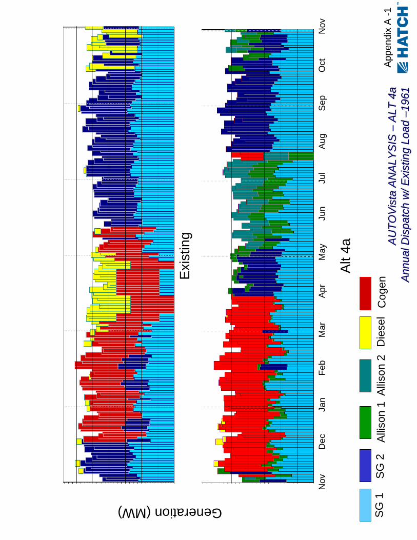
2.6 AUTO Vista Results Stacked bar charts indicating the most efficient dispatch of system resources as required to meet the system load are included in Appendix A for the existing condition, Alt 4a, and Alt 4b. The first charts compare the existing condition to the development alternatives for the 1961 water year, which is the 50% year as indicated in Table 2.1.
Tot al I nf lowYear Percent ile A cre-Feet
1969 10% 28,9001984 25% 30,8001954 25% 30,9001961 50% 33,2001957 75% 36,1001977 75% 37,9001989 90% 42,800
Average 34,400
0%
10%
20%
30%
40%
50%
60%
70%
80%
90%
100%
0 5 10 15 20 25 30 35 40 45Discharge (cfs)
Effic
ienc
y (%
)
0.0
0.5
1.0
1.5
2.0
2.5
3.0
3.5
4.0
4.5
5.0Po
wer
(MW
)Calculated Efficiency
Caculated Power

Copper Valley Electric Association, Inc. - Allison Lake Hydroelectric Project
Addendum – Final Feasibility Report
January 2011 Page 10
The annual generation for the base case of the existing load and resource condition for each of the 7 years included in the analysis is shown in Table 2.2 and the annual generation for Alt 4a and Alt 4b for the existing load condition is shown in Tables 2.3 and 2.4 below.
Table 2.2 Annual Generation – Existing Condition, Loads and Resources
Table 2.3 Annual Generation – Alt 4a w/ Existing Load
Table 2.4 Annual Generation – Alt 4b w/ Existing Load
Generation (MWh)Year Solomon Allison Total Hydro Diesel Cogen Total1969 51,900 0 51,900 11,300 23,100 86,4001984 55,200 0 55,200 8,100 23,000 86,4001954 55,700 0 55,700 7,600 23,000 86,4001961 59,700 0 59,700 6,100 20,600 86,4001957 58,500 0 58,500 7,200 20,700 86,4001977 61,800 0 61,800 3,100 21,500 86,4001989 62,100 0 62,100 4,400 19,900 86,400
Average 57,800 0 57,800 6,800 21,700 86,400
Generation (MWh)Year Solomon Allison Total Hydro Diesel Cogen Total1969 54,600 13,700 68,400 500 17,500 86,4001984 54,000 15,100 69,200 300 16,900 86,4001954 49,500 13,800 63,400 500 22,500 86,4001961 53,200 14,100 67,300 500 18,500 86,4001957 55,100 11,800 67,000 500 18,900 86,4001977 57,800 12,400 70,200 300 15,900 86,4001989 57,900 10,300 68,200 400 17,800 86,400
Average 54,600 13,000 67,700 400 18,300 86,400
Generation (MWh)Year Solomon Allison Total Hydro Diesel Cogen Total1969 55,100 15,300 70,400 500 15,500 86,4001984 55,000 16,200 71,200 400 14,800 86,4001954 51,900 13,600 65,500 500 20,300 86,4001961 55,300 14,400 69,800 400 16,200 86,4001957 56,100 12,900 69,000 500 16,800 86,4001977 59,300 12,900 72,200 500 13,700 86,4001989 59,300 10,900 70,100 500 15,800 86,400
Average 56,000 13,700 69,700 500 16,200 86,400

Copper Valley Electric Association, Inc. - Allison Lake Hydroelectric Project
Addendum – Final Feasibility Report
January 2011 Page 11
The annual generation for the base case of the additional 2MW load and resource condition for each of the 7 years included in the analysis is shown in Table 2.5 and the annual generation for Alt 4a and Alt 4b for the additional 2MW load condition is shown in Tables 2.6 and 2.7 below.
Table 2.5 Annual Generation – Existing Resources w/ 2 MW Additional Load
Table 2.6 Annual Generation – Alt 4a w/ 2 MW Additional Load
Generation (MWh)Year Solomon Allison Total Hydro Diesel Cogen Total1969 57,000 18,100 75,100 3,000 25,500 103,5001984 57,700 19,000 76,700 3,000 23,900 103,5001954 53,500 17,800 71,300 8,200 24,100 103,5001961 58,900 16,600 75,500 4,200 23,800 103,5001957 59,600 15,200 74,800 4,600 24,200 103,5001977 61,900 15,700 77,700 2,000 23,900 103,5001989 62,600 14,000 76,600 4,600 22,400 103,500
Average 58,700 16,600 75,400 4,200 24,000 103,500
Table 2.7 Annual Generation – Alt 4b w/ 2 MW Additional Load
The annual general benefits from the AUTO Vista Analyses for Alt 4a and Alt 4b can then be summarized for each load case as shown in Table 2.8 in terms of the incremental hydropower generation and associated reduction on thermal power as required to satisfy the system load for each of the alternatives under consideration. Please note that the minor differences between the hydro and thermal generation values for each alternative are due to rounding within the AUTO Vista modeling.
Generation (MWh)Year Solomon Allison Total Hydro Diesel Cogen Total1969 51,700 0 51,700 28,700 23,100 103,5001984 54,800 0 54,800 25,600 23,100 103,5001954 55,500 0 55,500 24,900 23,100 103,5001961 59,100 0 59,100 21,400 23,000 103,5001957 62,100 0 62,100 19,800 21,700 103,5001977 66,000 0 66,000 15,200 22,400 103,5001989 66,500 0 66,500 15,500 21,600 103,500
Average 59,400 0 59,400 21,600 22,600 103,500
Generation (MWh)Year Solomon Allison Total Hydro Diesel Cogen Total1969 58,200 19,000 77,200 900 25,400 103,5001984 58,500 20,200 78,700 1,000 23,900 103,5001954 55,600 17,800 73,400 5,900 24,200 103,5001961 60,400 17,100 77,500 2,300 23,700 103,5001957 61,300 15,600 76,900 2,600 24,100 103,5001977 63,800 15,700 79,500 300 23,700 103,5001989 63,800 14,900 78,600 2,500 22,400 103,500
Average 60,200 17,200 77,400 2,200 23,900 103,500

Copper Valley Electric Association, Inc. - Allison Lake Hydroelectric Project
Addendum – Final Feasibility Report
January 2011 Page 12
Table 2.8
Annual Benefits – Alt 4a & 4b
Resource Existing Alt 4a Alt 4b Existing Alt 4a Alt 4bHydro 57,800 67,700 69,700 59,400 75,400 77,400
Fossil 28,500 18,700 16,700 44,200 28,200 26,100
Total 86,300 86,400 86,400 103,600 103,600 103,500
Benefit 9,900 11,900 16,000 18,000
Existing Load - Generation (MWh) 2 MW Addition - Generation (MWh)
Copper Valley Electric Association, Inc. - Allison Lake Hydroelectric Project
Addendum – Final Feasibility Report
January 2011 Page 13
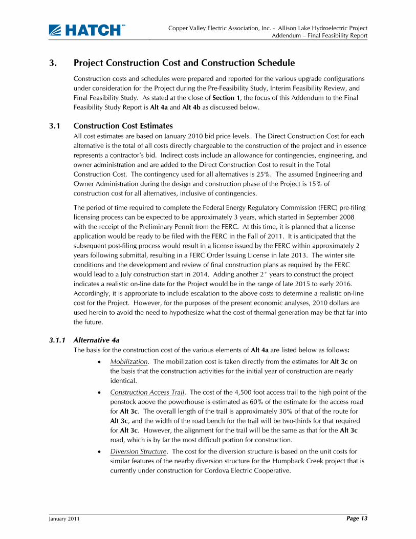
3. Project Construction Cost and Construction Schedule
Construction costs and schedules were prepared and reported for the various upgrade configurations under consideration for the Project during the Pre-Feasibility Study, Interim Feasibility Review, and Final Feasibility Study. As stated at the close of Section 1, the focus of this Addendum to the Final Feasibility Study Report is Alt 4a and Alt 4b as discussed below.
3.1 Construction Cost Estimates All cost estimates are based on January 2010 bid price levels. The Direct Construction Cost for each alternative is the total of all costs directly chargeable to the construction of the project and in essence represents a contractor’s bid. Indirect costs include an allowance for contingencies, engineering, and owner administration and are added to the Direct Construction Cost to result in the Total Construction Cost. The contingency used for all alternatives is 25%. The assumed Engineering and Owner Administration during the design and construction phase of the Project is 15% of construction cost for all alternatives, inclusive of contingencies.
The period of time required to complete the Federal Energy Regulatory Commission (FERC) pre-filing licensing process can be expected to be approximately 3 years, which started in September 2008 with the receipt of the Preliminary Permit from the FERC. At this time, it is planned that a license application would be ready to be filed with the FERC in the Fall of 2011. It is anticipated that the subsequent post-filing process would result in a license issued by the FERC within approximately 2 years following submittal, resulting in a FERC Order Issuing License in late 2013. The winter site conditions and the development and review of final construction plans as required by the FERC would lead to a July construction start in 2014. Adding another 2+ years to construct the project indicates a realistic on-line date for the Project would be in the range of late 2015 to early 2016. Accordingly, it is appropriate to include escalation to the above costs to determine a realistic on-line cost for the Project. However, for the purposes of the present economic analyses, 2010 dollars are used herein to avoid the need to hypothesize what the cost of thermal generation may be that far into the future.
3.1.1 Alternative 4a The basis for the construction cost of the various elements of Alt 4a are listed below as follows:
• Mobilization. The mobilization cost is taken directly from the estimates for Alt 3c on the basis that the construction activities for the initial year of construction are nearly identical.
• Construction Access Trail. The cost of the 4,500 foot access trail to the high point of the penstock above the powerhouse is estimated as 60% of the estimate for the access road for Alt 3c. The overall length of the trail is approximately 30% of that of the route for Alt 3c, and the width of the road bench for the trail will be two-thirds for that required for Alt 3c. However, the alignment for the trail will be the same as that for the Alt 3c road, which is by far the most difficult portion for construction.
• Diversion Structure. The cost for the diversion structure is based on the unit costs for similar features of the nearby diversion structure for the Humpback Creek project that is currently under construction for Cordova Electric Cooperative.

Copper Valley Electric Association, Inc. - Allison Lake Hydroelectric Project
Addendum – Final Feasibility Report
January 2011 Page 14
• Surface Pipeline / Penstock. The cost of the surface pipeline / penstock is based on the detailed estimates developed for the comparable penstock segments of Alt 3c as included in Appendix E of the FFS.
• Powerhouse. The costs for the major equipment within the 6.5 MW powerhouse are based on preliminary quotations from equipment suppliers while the cost for other lower cost items were obtained from in-house cost data and from recently obtained bid prices on similar construction.
• Switchyard. The switchyard cost is taken directly from the estimate for Alt 3c.
• Transmission. The transmission cost is taken directly from the estimate for Alt 3c.
The resulting construction cost estimate for Alt 4a is summarized in Table 3.1.
Table 3.1 Alternative 4a Total Construction Cost (Bid 1/2010)
Item1. Mobilization $1,573,0002. Construction Access Trail $2,916,0003. Dam, Intake & Spillway a. Diversion Structure $2,230,000 b. Spillway $0
$2,230,0004. Surface Penstock / Pipeline a. HDPE Pipeline $0 b. Steel Pipeline $5,176,000
Subtotal $5,176,0005. Powerhouse a. Civil Works $2,594,000 b. Turbine & Generator $4,710,000 c. Misc. Mech. Equip. $683,000 d. Misc. Elec. Equip. $1,015,000 e. Bridge Crane $187,000
Subtotal $9,189,0006. Switchyard $525,0007. Transm. & Interconnection $310,000Direct Construction Cost (Bid 1/09) $21,919,000Escalation -$590,000
Direct Construction Cost (Bid 1/10) $21,329,000Contingencies $6,076,000Engineering & Owner Admin. $4,111,000Total Construction Cost (Bid 1/10) $32,106,000
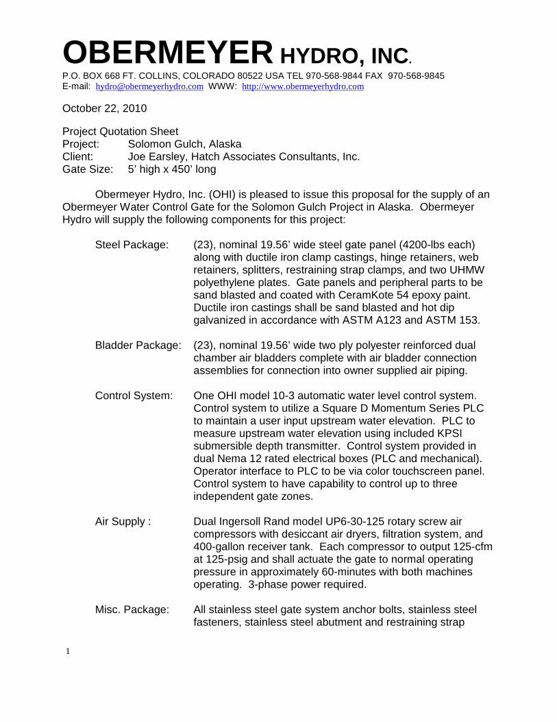
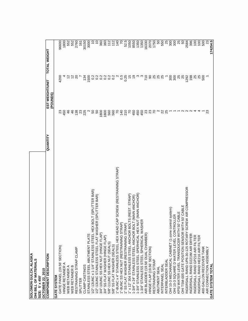
3.1.2 Alternative 4b The cost for the addition of a Obermeyer Gate 5 feet in height on the top of the Solomon Gulch Spillway was considered on its own as an incremental feature for the CVEA system. The cost of this addition is based on a preliminary quotation for the gate materials and a configuration as suggested by the Obermeyer company. The costs for modifications to the existing spillway and installation of

Copper Valley Electric Association, Inc. - Allison Lake Hydroelectric Project
Addendum – Final Feasibility Report
January 2011 Page 15
the gate are based on estimated quantities of construction and in-house unit costs. The resulting cost for Alt 4b is summarized in Table 3.2.
Table 3.2 Alternative 4b Total Construction Cost (Bid 1/2010)
ItemLabor $2,106,000Equipment $235,000Materials $1,951,000Direct Construction Cost (Bid 1/10) $4,292,000Contingencies $858,000Engineering & Owner Admin. $773,000Total Construction Cost (Bid 1/10) $5,923,000
3.2 Construction Schedule The construction schedule for Alt 4a and Alt 4b is primarily controlled by the following major factors:
• Delivery time for major powerhouse equipment; • Access to Allison Lake for construction activity; • Four month window for construction activity at Allison Lake, generally from mid-July to mid-
October depending on conditions; and • Earliest most reasonable construction start in 2014 based on estimated timing of FERC
license issuance (as discussed above).
A similar approach has been used to develop a schedule for each alterative relative to the purposes of the cost estimates presented above and the annual costs presented below for each alternative. The schedule for Alt 4a is presented in Figure 3.3 as an example thereof.

Copper Valley Electric Association, Inc. - Allison Lake Hydroelectric Project
Addendum – Final Feasibility Report
January 2011 Page 16
Figure 3.3 Alternative 4a Construction Schedule
3.3 Economic Analysis Annual costs of the Project can be apportioned into fixed and variable costs. The fixed amount includes amortization of the Total Capital Requirements less earnings on Reserves and is based on 7% interest rate financing over a 30-year term. Variable annual costs escalate each year and include operation and maintenance (O&M) costs, administrative and general expenses, interim replacements, and insurance. The basic assumptions for determining the annual fixed and variable costs of the Project are shown in Table 3.3.
Table 3.3 Basic Assumptions for Economic Analyses
Item ValueConstruction Period (Alt 4a) 25 months Financing Term 30 years Financing Interest Rate 7% Reinvestment Rate Same as financing Escalation of Project Costs 3% annually Financing Reserve 1 year of debt service Financing Expenses 3% of Total Investment Cost Variable Annual Costs $500,000
Blaze trail to diversion structure
and foundation prep
Access to powerhouse
Laydown areas - powerhouse
Powerhouse foundation prep
Warehouses / offices
Month 1 Month 2 Month 3 Month 4Month 1 Month 2 Month 3 Month 4 Month 1 Month 2 Month 3 Month 4
Powerhouse
Switchyard
Transmission Line
2nd Season - 20151st Season - 2014 3rd Season - 2016
n Activity Duration (weeks)
Housing: Man-Camp in Valdez Housing: Man-Camp in Valdez
Access road to 45+00
100’ / day – single shift 9
Diversion structure
Penstock to 25+00
9
Penstock to 55+00 to 25+0013
9Penstock, PH to 55+00
Final – anchor blocks, etc.8
Blaze trail to diversion structure
and foundation prep
Access to powerhouseAccess to powerhouse
Laydown areas - powerhouse
Powerhouse foundation prep
Warehouses / offices
Month 1 Month 2 Month 3 Month 4Month 1 Month 2 Month 3 Month 4Month 1 Month 2 Month 3 Month 4 Month 1 Month 2 Month 3 Month 4Month 1 Month 2 Month 3 Month 4
Powerhouse
Switchyard
Transmission Line
2nd Season - 20151st Season - 2014 3rd Season - 2016
n Activity Duration (weeks)n Activity Duration (weeks)
Housing: Man-Camp in Valdez Housing: Man-Camp in Valdez
Access road to 45+00
100’ / day – single shift 9
Access road to 45+00
100’ / day – single shift 9100’ / day – single shift 9
Diversion structure
Penstock to 25+00
9
Penstock to 55+00 to 25+0013
9Penstock, PH to 55+00
Final – anchor blocks, etc.8

Copper Valley Electric Association, Inc. - Allison Lake Hydroelectric Project
Addendum – Final Feasibility Report
January 2011 Page 17
3.3.1 Cost of Power – Alternative 4a The Total Investment cost includes interest during construction (IDC) over an assumed 25-month construction period. As outlined above, we have assumed that construction at the project site would come to a stop during the winter months, with the exception of equipment installation within the powerhouse structure. The development of the annual cost for Alt 4a is shown in 2010 dollars on Table 3.4.
Table 3.4 Alternative 4a – First Year Annual Cost (2010 dollars)
As discussed in Section 2 above, the unit cost of power becomes a function of the extent to which the power available from the Project can actually contribute to the CVEA system load on a day-to-day, hour-to-hour basis. In this regard, three scenarios are presented including:
1. The AUTO Vista studies performed indicate that a total of 9,900,000 kWh from the Project can be used within the existing CVEA system load.
2. With an additional 2 MW of load within the CVEA system, the AUTO Vista studies performed also indicate that a total of 16,000,000 kWh from the Project can be effectively utilized.
3. The review of the available flow data for Allison Creek indicates that a 6.5 MW run-of-river project at the site would have the capability to produce a total of 23,300,000 kWh at such time that the CVEA system load that would not constrain its operation.
The cost of power resulting from these three scenarios is presented in Table 3.5.
Item CostTotal Construction Cost (Bid 1/10) $32,106,000 Interest During Construction 2,435,000Total Investment Cost $34,541,000 Reserve Fund 3,127,000 Financing & Legal 1,036,000 Working Capital 100,000Total Capital Requirements (1/10) $38,804,000
Annual Cost Debt Service $3,127,000 O&M Cost 280,000 Administrative & General 112,000 Insurance 50,000 Interim Replacements 50,000 Earnings on Reserve Fund (219,000)
Total First-Year Annual Cost $3,400,000

Copper Valley Electric Association, Inc. - Allison Lake Hydroelectric Project
Addendum – Final Feasibility Report
January 2011 Page 18
Table 3.5 Alternative 4a – Cost of Power
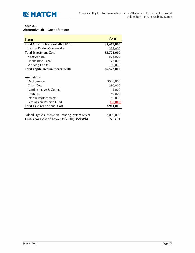
3.3.2 Cost of Power – Alternative 4b As indicated by the results included in Table 2.8, the addition of the Obermeyer gate to the Solomon Gulch spillway adds 2,000,000 kWh to the energy for the Alt 4a development with and without the anticipated additional 2 MW of load to the CVEA system. Further, the Alt 4b contribution to the CVEA system load is essentially the same without a run-of-river development of Allison Creek. The resulting cost of power during the first year of operation is shown in Table 3.6.
Item Value
Alt 4a with Existing System Load (kWh) 9,900,000 First-Year Cost of Power (1/2010) ($/kWh) $0.343
Alt 4a with 2 MW Additional Load (kWh) 16,000,000 First-Year Cost of Power (1/2010) ($/kWh) $0.213
Alt 4a with Expanded CVEA System (kWh) 23,300,000 First-Year Cost of Power (1/2010) ($/kWh) $0.146
Total First-Year Annual Cost $3,400,000
Copper Valley Electric Association, Inc. - Allison Lake Hydroelectric Project
Addendum – Final Feasibility Report
January 2011 Page 19
Table 3.6 Alternative 4b – Cost of Power
Item Cost Total Construction Cost (Bid 1/10) $5,469,000 Interest During Construction 255,000Total Investment Cost $5,724,000 Reserve Fund 526,000 Financing & Legal 172,000 Working Capital 100,000Total Capital Requirements (1/10) $6,522,000
Annual Cost Debt Service $526,000 O&M Cost 280,000 Administrative & General 112,000 Insurance 50,000 Interim Replacements 50,000 Earnings on Reserve Fund (37,000)Total First-Year Annual Cost $981,000
Added Hydro Generation, Existing System (kWh) 2,000,000First-Year Cost of Power (1/2010) ($/kWh) $0.491
Copper Valley Electric Association, Inc. - Allison Lake Hydroelectric Project
Addendum – Final Feasibility Report
January 2011 Page 20
4. Regulatory and Environmental Considerations
Section 5 of the FFS presents our full evaluation of the regulatory and environmental considerations relative to hydroelectric project development in general, and specifically, to a 4.5 MW storage project at Allison Lake. Regulatory and environmental work continues to proceed toward preparation of an Application for License to the FERC. This section presents the impacts on the ongoing regulatory process and environmental investigations of the additional identified alternatives, Alt 4a and Alt 4b.
4.1 Alternative 4a
4.1.1 Regulatory Considerations CVEA issued a Preliminary Application Document (PAD), including the Draft Application for License and Preliminary Draft Environmental Assessment (PDEA) (Draft Application) for the Allison Lake Project on April 13, 2010. The PAD, including the Draft Application for License, described a proposed 4.5 MW storage project and was prepared under the regulation for Major Unconstructed Project Less Than 5 MW pursuant to 18 CFR 4.61.
The run-of-river modification to the Project would have an installed capacity of 6.5 MW and therefore would be greater than 5 MW and the Application for License would be prepared pursuant to 18 CFR 4.41, Major Unconstructed Project Greater Than 5 MW. This change in the applicable FERC regulation would not significantly affect either the environmental work to date or the PDEA. However, the change does necessitate that the engineering information be modified and expanded as required under 18 CFR 4.41.
The change from the 4.5 MW storage project to the proposed 6.5 MW run-of-river project will require:
1. Revision of the PDEA to present the run-of-river project description and related operation as it differs from the storage project description and operation.
2. Preparation of the revised engineering exhibits. The Draft Application as provided on April 13, 2010, included a single engineering exhibit (Exhibit A) for the proposed 4.5 MW storage project containing the required engineering information pursuant to 18 CFR 4.61. The change to the proposed 6.5 MW run-of-river project changes the applicable FERC regulation to 18 CFR 4.41 and the engineering exhibits expand to four exhibits (Exhibits A through D), each containing greater detail and additional information beyond the single engineering exhibit previously prepared.
3. Preparation and issuance of Revised Scoping Document 1 (SD1). SD1 was issued on April 22, 2010, and scoping meetings were held on May 10 and 12, 2010. The process for issuing a revised SD1 was discussed with FERC staff. CVEA will not be required to hold new scoping meetings, nor conduct an additional site visit (initial site visit was in 2005). FERC Staff recommended that CVEA:
a. Issue a revised SD1 along with a revised PAD; and
b. Following provision of the revised documents, schedule a teleconference with the resource agencies and other interested participants to discuss the revised proposed Project.
In light of the above, the level of effort going forward for document preparation for the 6.5 MW run-of-river option would be greater than that required for the 4.5 MW storage option due to the
Copper Valley Electric Association, Inc. - Allison Lake Hydroelectric Project
Addendum – Final Feasibility Report
January 2011 Page 21
redundancies involved with following the 18 CFR 4.41 process. However, the downstream benefits in the activities for development of the run-of-river project would be greatly increased as discussed below, greatly overweighing the additional effort required for document preparation and the licensing process itself.
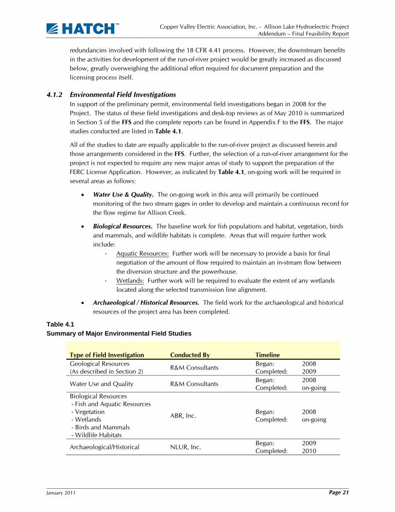
4.1.2 Environmental Field Investigations In support of the preliminary permit, environmental field investigations began in 2008 for the Project. The status of these field investigations and desk-top reviews as of May 2010 is summarized in Section 5 of the FFS and the complete reports can be found in Appendix F to the FFS. The major studies conducted are listed in Table 4.1.
All of the studies to date are equally applicable to the run-of-river project as discussed herein and those arrangements considered in the FFS. Further, the selection of a run-of-river arrangement for the project is not expected to require any new major areas of study to support the preparation of the FERC License Application. However, as indicated by Table 4.1, on-going work will be required in several areas as follows:
• Water Use & Quality. The on-going work in this area will primarily be continued monitoring of the two stream gages in order to develop and maintain a continuous record for the flow regime for Allison Creek.
• Biological Resources. The baseline work for fish populations and habitat, vegetation, birds and mammals, and wildlife habitats is complete. Areas that will require further work include:
- Aquatic Resources: Further work will be necessary to provide a basis for final negotiation of the amount of flow required to maintain an in-stream flow between the diversion structure and the powerhouse.
- Wetlands: Further work will be required to evaluate the extent of any wetlands located along the selected transmission line alignment.
• Archaeological / Historical Resources. The field work for the archaeological and historical resources of the project area has been completed.
Table 4.1
Summary of Major Environmental Field Studies
Type of Field Investigation Conducted By Timeline Geological Resources (As described in Section 2)
R&M Consultants Began: 2008 Completed: 2009
Water Use and Quality R&M Consultants Began: 2008 Completed: on-going
Biological Resources - Fish and Aquatic Resources - Vegetation - Wetlands - Birds and Mammals - Wildlife Habitats
ABR, Inc. Began: 2008 Completed: on-going
Archaeological/Historical NLUR, Inc. Began: 2009 Completed: 2010

Copper Valley Electric Association, Inc. - Allison Lake Hydroelectric Project
Addendum – Final Feasibility Report
January 2011 Page 22
4.1.3 Environmental Considerations While the regulatory framework for Alt 4a is more detailed than that associated for Alt 3c, the associated scope of environmental issues is greatly reduced. The more significant elements of this comparison are:
1. Allison Lake would be left in its natural state in the case of Alt 4a, which has not been the case for all arrangements previously considered. The lake would have been drawn down by as much as 100 feet during the winter season in the lake-tap alternatives. Conversely, the lake would have been raised 43 feet in the case of Alt 3c thereby inundating the existing east and west shorelines and the delta at the south end of the lake.
2. The construction activity of the dam near the outlet of the lake would disturb a significant area with attendant concerns for water quality within Allison Creek to a much greater extent than would be associated with the construction of the diversion structure for Alt 4a.
3. The construction of the diversion structure for Alt 4a would not require that a road be constructed to the outlet of Allison Lake nor the extensive amount of traffic associated with the construction of the major dam structure included with Alt 3c.
4. In the case of Alt 3c, there would be a potential for seepage beneath and around the dam resulting in a loss of water available for hydropower generation as well as changed ground water conditions in the glacial moraine downstream of Allison Lake. While not likely, any seepage that may occur at the location of the diversion structure associated with Alt 4a would be very minor.
5. In the case of Alt 4a, the flow regime within Allison Creek would remain unchanged between Allison Lake and the diversion structure as well as within the reach downstream of the powerhouse, the latter being the area of primary concern for the habitat for both resident and anadromous fish species.
All of these factors would greatly reduce the level of effort required for Alt 4a as compared to Alt 3c for agency consultation throughout the remaining licensing activities as well as for environmental monitoring during construction and operation of the project.
4.2 Alternative 4b
4.2.1 Regulatory Considerations An amendment to the existing Solomon Gulch Project FERC License (No. P-2742) would be required for the proposed five foot raise in the normal maximum water surface of Solomon Lake as proposed for Alt 4b. The amendment would require that agency consultation take place in a manner comparable to that currently anticipated for the Allison Lake development. As part of the consultation process, issues that were not resolved according to current practice during the original licensing process would likely be revisited by existing agency staff.
4.2.2 Environmental Field Studies Ostensibly, the environmental field studies would focus on habitat values within the additional area to be submerged surrounding Solomon Lake as the result of the proposed five foot raise in the normal maximum water surface of Solomon Lake. It can be expected, however, that agency consultation would result in requests for further studies with regard to other aspects of the project that were not studied in accordance with current practice as part of the original licensing process.
Copper Valley Electric Association, Inc. - Allison Lake Hydroelectric Project
Addendum – Final Feasibility Report
January 2011 Page 23
4.2.3 Environmental Considerations No specific concerns of a fatal flaw nature have been identified with regard to the environmental effects of the proposed five foot raise in the normal maximum water surface of Solomon Lake as proposed for Alt 4b.
Copper Valley Electric Association, Inc. - Allison Lake Hydroelectric Project
Addendum – Final Feasibility Report
January 2011 Page 24
5. Conclusions and Recommendations
5.1 Conclusions
5.1.1 Alternative 4a In addition to the general conclusions relating to the development of a hydropower project in the Allison Creek basin as provided in the FFS, conclusions specific to the run-of-river Alt 4a gained as the result of the present evaluation include the following:
• The scope of the project as proposed for the run-of-river Alt 4a is significantly reduced from that associated with Alt 3c.
• A run-of-river Alt 4a development of the Allison Creek basin can produce 23.3 GWh of energy on an average annual basis within the environment of an unconstrained system load.
• A run-of-river Alt 4a development of the Allison Creek basin would produce 9.8 GWh of energy on an average annual basis within the existing CVEA system load. The project is not cost effective under this load condition.
• With the addition of 2 MW to the CVEA system load, the Alt 4a average annual contribution to the CVEA system load would increase to 16.0 GWh. On this basis, the project would be competitive with the cost of diesel generation.
• Further increases in the CVEA system load would in turn result in a further reduction in the cost of power from Alt 4a.
• The reduced scale of the hydropower development of the Allison Creek basin as offered by Alt 4a would in turn minimize the risk of construction cost overruns relative to that potentially associated with Alt 3c.
• The diversion structure proposed for Alt 4a would entail a minimal, if any, risk of seepage or other dam safety related issues in contrast to that potentially associated with the large dam at the outlet of Allison Lake as proposed for Alt 3c.
• On the basis that the installed capacity of the run-of-river Alt 4a is expected to be greater than 5 MW, FERC 18 CFR 4.41 would be the required regulation for the preparation of a FERC License Application for the project.
• The reduced scale of the hydropower development of the Allison Creek basin as offered by Alt 4a will result in an overall reduction in environmental effects relative to that associated with Alt 3c.
• In contrast to any of the storage project arrangements as previously considered for development of the Allison Creek basin, the run-of-river configuration as proposed for Alt 4a would maintain the existing flow and temperature regimes downstream of powerhouse. This would be a major advantage for Alt 4a owing to the critical importance of this reach of Allison Creek to resident and anadromous fish populations.
• Alt 4a is superior to Alt 3c in all respects.
5.1.2 Alternative 4b Conclusions specific to Alt 4b gained as the result of the present evaluation include the following:
• The addition of inflatable gates to the Solomon Gulch Spillway as proposed for Alt 4b would add approximately 2 GWh of average annual energy to the CVEA system for service to all system load and resource conditions considered for the project, existing and future.
Copper Valley Electric Association, Inc. - Allison Lake Hydroelectric Project
Addendum – Final Feasibility Report
January 2011 Page 25
• The addition of inflatable gates to the Solomon Gulch Spillway as proposed for Alt 4b would require an amendment to the existing FERC License for the Solomon Gulch Project.
• On the basis of the energy potential and cost estimates prepared for this evaluation, the addition of inflatable gates to the Solomon Gulch Spillway as proposed for Alt 4b would not currently be economically viable relative to the other resources available to the CVEA.
5.2 Recommendations Based on the conclusions referenced and outlined above, we provide the following recommendations:
• Adopt Alt 4a as the preferred alternative for the development of the hydroelectric potential of the Allison Creek basin;
• Terminate further consideration of Alt 3c and Alt 4b;
• Complete the analysis of the environmental effects of a hydropower development within the Allison Creek basin on the basis of Alt 4a;
• Optimize the capacity of the powerhouse for the run-of-river Alt 4a; and
• Prepare a FERC License Application for Alt 4a pursuant to the provisions of 18 CFR 4.41.

Copper Valley Electric Association, Inc. - Allison Lake Hydroelectric Project
Addendum – Final Feasibility Report
January 2011 Page 26
6. References
1. Hatch Acres Corporation, Allison Lake Hydropower Development – FINAL FEASIBILITY STUDY, prepared for Copper Valley Electric Association, May 2010 .
2. HDR Engineering, Inc., SOLOMON GULCH HYDROELECTRIC PROJECT – RESERVOIR CAPACITY – FEASIBILITY STUDY, prepared for Copper Valley Electric Association, November 1991.

Appendix AAlt 4a System Dispatch
Nov
Dec
Apr
May
Jan
Jun
Mar
Feb
Sep
Oct
Nov
Aug
Jul
Alt
4a
Generation (MW)
AU
TOV
ista
AN
ALY
SIS
A
UTO
Vis
ta A
NA
LYS
IS ––
ALT
4a
ALT
4a
Ann
ual D
ispa
tch
w/ E
xist
ing
Load
A
nnua
l Dis
patc
h w
/ Exi
stin
g Lo
ad ––
1961
1961
SG
2A
lliso
n 1
Die
sel
Alli
son
2C
ogen
SG
1
Exi
stin
g
App
endi
x A
-1

Nov
Dec
Apr
May
Jan
Jun
Mar
Feb
Sep
Oct
Nov
Aug
Jul
Alt
4a
Generation (MW)
AU
TOV
ista
AN
ALY
SIS
A
UTO
Vis
ta A
NA
LYS
IS ––
ALT
4a
ALT
4a
Ann
ual D
ispa
tch
w/ 2
MW
Add
ed L
oad
Load
A
nnua
l Dis
patc
h w
/ 2 M
W A
dded
Loa
d Lo
ad ––
1961
1961
SG
2A
lliso
n 1
Die
sel
Alli
son
2C
ogen
SG
1
Exi
stin
g +
2 M
W
App
endi
x A
-2

Appendix BObermeyer Gate –
Cost Estimate

SOLOMON GULCH HYDROELECTRIC FACILITY OBERMEYER GATE INSTALLATIONConstruction Cost SummaryNEW INSTALLATIONBased on Dick Freeman's Avista- Nine Mile estimate dated Dec 18, 2007 and Jim Rutherford's Humpback Creek Estimate, 03/2009, and Obermeyer quote dated October 22, 2010
TOTAL LABOR EQUIPMENT MATERIALS
No. ItemCrew Size
Hours / Crew Hours Rate Total Item Qty Rate Weeks Total Item Qty Rate Total
1 Mobilization $57,200 $42,000 $15,200 $07 80 560 75 $42,000 966 Loader 1 4000 2 $8,000 1 $0
Flatbed trucks 2 1500 2 $6,000Pettibone Fork Lift 1 600 2 $1,200
2 Remove Existing Splitter Piers $67,800 $52,500 $4,800 $10,5007 100 700 75 $52,500 600 cfm compressor 1 1800 2 $3,600 Miscellaneous (20% of labor) 10500 1 $10,500
Pettibone Fork Lift 1 600 2 $1,200$0
3 Drill and Set Anchors - 112 each $210,320 $144,000 $31,200 $35,1208 240 1920 75 $144,000 $0 Miscellaneous 5000 1 $5,000
$0 Anchors 1" x 15 ft x 56 ea x 2.67 lbs ea. 5000 3 $15,0000 600 cfm compressor 1 1800 4 $7,200 Grout 1680 9 $15,120
airtracks 2 2700 4 $21,600Pettibone Fork Lift 1 600 4 $2,400
4 Pour Concrete $311,366 $180,000 $70,400 $60,966
Description: Pour additional spillway concete to anchor Obermeyer Gate, middle spitter wall and create a right abutment. Approx. 524 CY of concrete with a 1:2:4 mix, 4 x 60 hour weeks $0Labor - 10 men working 6 (10) hour days 10 240 2400 75 $180,000
Generator - 60 kw 1 900 4 $3,600 Miscellaneous 5000 1 $5,000Compressor - 66 cfm 1 2100 4 $8,400 Form lumber 27600 $0.50 $13,800Mix truck 1 5500 4 $22,000 Rebar - cut, bundled in town 32390 $0.80 $25,912Water truck 1 2500 4 $10,000 Cement 72 $90 $6,480Concrete pump 10 600 4 $24,000 Sand 171 $10 $1,710Pettibone Fork Lift 1 600 4 $2,400 Gravel 281 $12 $3,372Misc vibrators, saws, drills 1 0 4 $0 Additives/Curing (add 10% to all) 1.38 $3,400 $4,692
5 Install Air Piping Along Crest $78,540 $60,000 $5,800 $12,7408 100 800 75 $60,000 600 cfm compressor 1 800 2 $1,600
flatbed truck 1 1500 2 $3,000Pettibone Fork Lift 1 600 2 $1,200
2" pipe with fittings, galvanized 530 20 $10,600miscellaneous 2140 1 $2,140
12 03 2010 Obermeyer Annual Cost_arg_joee.xls

SOLOMON GULCH HYDROELECTRIC FACILITY OBERMEYER GATE INSTALLATIONConstruction Cost SummaryNEW INSTALLATIONBased on Dick Freeman's Avista- Nine Mile estimate dated Dec 18, 2007 and Jim Rutherford's Humpback Creek Estimate, 03/2009, and Obermeyer quote dated October 22, 2010
TOTAL LABOR EQUIPMENT MATERIALS
No. ItemCrew Size
Hours / Crew Hours Rate Total Item Qty Rate Weeks Total Item Qty Rate Total
6 Set Obermeyer Assemblies in Place $1,764,325 $234,000 $43,600 $1,486,72513 240 3120 75 $234,000 $0
Pettibone Fork Lift 1 600 4 $2,400 Obermeyer $1,486,72560 ton crane 1 7000 4 $28,000 2 each 225' long x 5' high, assumed 600 cfm compressor 1 1800 4 $7,200 same cost as AVISTA, 9 mileflatbed truck 1 1500 4 $6,000 (250' long x 10' high)
7 Install Abutment Seal Plates (both ends) $479,400 $405,000 $50,400 $24,00015 360 5400 75 $405,000 $0
Pettibone Fork Lift 1 600 6 $3,600 Drill bits, epoxy grout 14000 1 $14,000600 cfm compressor 1 1800 6 $10,800 Anchors 600 1 $600mish air tools 13500 1 2 $27,000 Concrete 1200 1 $1,200flatbed truck 1 1500 6 $9,000 Form lumber 500 2 $1,000
Handrail platforms (lbs) 1440 5 $7,200
8 Install Compressor, MCC, Local Controls $78,000 $60,000 $12,000 $6,0008 100 800 75 $60,000 flatbed truck 1 1500 2 $3,000 Miscellaneous 6000 1 $6,000
10 Ton Crane 1 7000 1 $7,000Miscellaneous 1 1000 2 $2,000Pettibone Fork Lift 1 600 2
9 Raise Reservoir, Startup, Turnover $34,000 $30,000 $2,000 $2,0004 100 400 75 $30,000 Miscellaneous 2000 1 1 $2,000 Miscellaneous 2000 1 $2,000
SUBTOTAL $3,080,951 80 1560 16100 $1,207,500 $235,400 $1,638,051
Supervision (% of labor) $301,875 25% $301,875Overhead (% of labor) $181,125 15% $181,125Overtime factor (% of total labor) $169,050 10% $169,050Profit on labor (% of labor) $148,764 8% $148,764Profit on materials (% of labor) $81,903 5% $81,903Contigency (20%) $792,734Engineering & Owqner Administration (15%) $713,460SUBTOTAL $5,469,861
12 03 2010 Obermeyer Annual Cost_arg_joee.xls
1
OBERMEYER HYDRO, INC. P.O. BOX 668 FT. COLLINS, COLORADO 80522 USA TEL 970-568-9844 FAX 970-568-9845 E-mail: [email protected] WWW: http://www.obermeyerhydro.com October 22, 2010 Project Quotation Sheet Project: Solomon Gulch, Alaska Client: Joe Earsley, Hatch Associates Consultants, Inc. Gate Size: 5’ high x 450’ long Obermeyer Hydro, Inc. (OHI) is pleased to issue this proposal for the supply of an Obermeyer Water Control Gate for the Solomon Gulch Project in Alaska. Obermeyer Hydro will supply the following components for this project:
Steel Package: (23), nominal 19.56’ wide steel gate panel (4200-lbs each) along with ductile iron clamp castings, hinge retainers, web retainers, splitters, restraining strap clamps, and two UHMW polyethylene plates. Gate panels and peripheral parts to be sand blasted and coated with CeramKote 54 epoxy paint. Ductile iron castings shall be sand blasted and hot dip galvanized in accordance with ASTM A123 and ASTM 153.
Bladder Package: (23), nominal 19.56’ wide two ply polyester reinforced dual
chamber air bladders complete with air bladder connection assemblies for connection into owner supplied air piping.
Control System: One OHI model 10-3 automatic water level control system.
Control system to utilize a Square D Momentum Series PLC to maintain a user input upstream water elevation. PLC to measure upstream water elevation using included KPSI submersible depth transmitter. Control system provided in dual Nema 12 rated electrical boxes (PLC and mechanical). Operator interface to PLC to be via color touchscreen panel. Control system to have capability to control up to three independent gate zones.
Air Supply : Dual Ingersoll Rand model UP6-30-125 rotary screw air
compressors with desiccant air dryers, filtration system, and 400-gallon receiver tank. Each compressor to output 125-cfm at 125-psig and shall actuate the gate to normal operating pressure in approximately 60-minutes with both machines operating. 3-phase power required.
Misc. Package: All stainless steel gate system anchor bolts, stainless steel
fasteners, stainless steel abutment and restraining strap

2
anchor bolts, interpanel seals, three copies of engineering drawings and calculations, and three copies of operation and maintenance manuals.
Obermeyer Hydro is pleased to offer this complete package FOB Wellington,
Colorado for the sum total of USD 1,486,725.00. This price is valid until November 30, 2010. Shop drawings will be available within 4-weeks of purchase order. Delivery of gate shall be in accordance with mutually agreed upon project schedule
The above prices specifically exclude the following items:
1. Interconnecting wiring or piping. 2. Building for housing compressor and controls. 3. Installation except for any purchased supervision and training. 4. Any needed anchor bolt epoxy. 5. Bid, supply, or performance bond. 6. Federal, state, or any local taxes. In addition to the above equipment supply package OHI also recommends the
following installation supervision and owner training program: Trip One: Ten day on-site installation consulting trip by OHI technical during
gate installation. Purpose of the trip is to supervise the installation of the gate and the control building equipment.
Trip Three: Two day system start-up and owner training trip. Day one will be
dedicated to gate testing and day two will be for owner training and Operation and Maintenance manual review.
The price for the listed installation supervision and owner training program is USD
12,000.00. Additional on-site services are available for USD 1000.00 per day plus any added travel related expenses.
As all parts are custom manufactured, a thirty percent (30%) deposit will be required with the placement of an order. The balance, less five percent (10%) retention shall be upon shipping from Wellington, Colorado. The retention shall be due net sixty days after shipping from Wellington, Colorado or upon commissioning of gate whichever comes first. OHI reserves the right to invoice for partial shipments. All parts manufactured by Obermeyer Hydro are offered and guaranteed as outlined in standard OHI sales agreement. Items that are supplied, but not manufactured by Obermeyer Hydro, are covered by the original manufacturer’s warranty. Sincerely, Obermeyer Hydro, Inc. Robert Eckman Vice President
SO
LOM
ON
GU
LCH
, ALA
SK
AO
HI B
ILL
OF
MA
TER
IALS
SIZ
E:
5' x
450
'O
CTO
BE
R 2
2, 2
010
CO
MP
ON
EN
T D
ES
CR
IPTI
ON
QU
AN
TITY
ES
T W
EIG
HT/
UN
ITTO
TAL
WE
IGH
T(P
OU
ND
S)
GA
TE S
YS
TEM
G
AT
E P
AN
EL
(19.
56' S
EC
TIO
N)
2342
0096
600
H
ING
E R
ET
AIN
ER
A45
04
1800
W
EB
RE
TA
INE
R A
4612
552
W
EB
RE
TA
INE
R B
4612
552
R
ES
TR
AIN
ING
ST
RA
P C
LAM
P13
820
2760
S
PLI
TT
ER
237
161
C
LAM
P C
AS
TIN
GS
225
134
3015
0
ST
AIN
LES
S S
TE
EL
AB
UT
ME
NT
PLA
TE
215
0030
00
1/2
"-13
UN
C x
1-1
/4"
ST
AIN
LES
S S
TE
EL
HE
X B
OLT
(S
PLI
TT
ER
BA
R)
500.
210
1
/2"-
13U
NC
ST
AIN
LES
S S
TE
EL
FLA
T W
AS
HE
R (
SP
LIT
TE
R B
AR
)50
0.2
10
3/4
"-10
UN
C S
S H
EX
NU
T (
HIN
GE
FLA
P)
1800
0.2
360
3
/4"
SS
FLA
T W
AS
HE
R (
HIN
GE
FLA
P)
1800
0.2
360
5
/8"-
11U
NC
SS
HE
X N
UT
(S
EA
LS)
560
0.2
112
5
/8"
SS
FLA
T W
AS
HE
R (
SE
ALS
)56
00.
211
2
1"-
8UN
C x
4"
ST
AIN
LES
S S
TE
EL
HE
X H
EA
D C
AP
SC
RE
W (
RE
ST
RA
ININ
G S
TR
AP
)70
214
0
1"-
8UN
C S
S H
EX
NU
T (
RE
ST
RA
ININ
G S
TR
AP
)14
00.
570
1
" S
S F
LAT
WA
SH
ER
(R
ES
TR
AIN
ING
ST
RA
P)
210
0.25
52.5
1
" x
12"
304
ST
AIN
LES
S S
TE
EL
AN
CH
OR
BO
LTS
(R
ES
T. S
TR
AP
)70
1510
50
1-3
/4"
x 24
" S
TA
INLE
SS
ST
EE
L A
NC
HO
R B
OLT
(M
AIN
AN
CH
OR
)45
019
8550
1
-3/4
" S
TA
INLE
SS
ST
EE
L S
PE
RH
ICA
L H
EX
NU
T (
MA
IN A
NC
HO
R)
450
313
50
1-3
/4"
ST
AIN
LES
S S
TE
EL
SP
HE
RIC
AL
WA
SH
ER
450
313
50
AIR
BLA
DD
ER
(19
.56'
DU
AL
CH
AM
BE
R)
2371
016
330
H
ING
E F
LAP
(19
.56'
SE
CT
ION
)23
9020
70
RE
ST
RA
ININ
G S
TR
AP
70
2517
50
AB
UT
ME
NT
SE
AL
225
50
IN
TE
RP
AN
EL
SE
AL
2225
550
I
NT
ER
BLA
DD
ER
SE
AL
251
25
OH
I 10-
3 M
EC
HA
NIC
AL
CA
BIN
ET
(1-
zone
con
trol
sys
tem
)1
300
300
O
HI 1
0-3
SQ
UA
RE
D W
AT
ER
LE
VE
L C
ON
TR
OLL
ER
130
030
0
KP
SI W
AT
ER
LE
VE
L T
RA
NS
DU
CE
R W
ITH
50'
CA
BLE
125
25
OH
I TS
M-0
05 G
AT
E P
OS
ITIO
N S
EN
SO
R W
ITH
50'
CA
BLE
225
50
IN
GE
RS
ALL
RA
ND
UP
6-30
-125
RO
TA
RY
SC
RE
W A
IR C
OM
PR
ES
SO
R
212
9225
84
IN
GE
RS
ALL
RA
ND
D22
1IM
AIR
DR
YE
R2
198
396
I
NG
ER
SA
LL R
AN
D G
P21
6 A
IR F
ILT
ER
425
100
I
NG
ER
SA
LL R
AN
D H
E21
6 A
IR F
ILT
ER
425
100
4
00-G
ALL
ON
RE
CE
IVE
R T
AN
K1
500
500
A
IR C
ON
NE
CT
ION
AS
SE
MB
LY23
123
GA
TE S
YS
TEM
TO
TAL
1742
54.5

END