Embed Size (px)
Citation preview

INSTALLATIONINSTRUCTIONS
1www.revmaxconverters.com
INSTALLATIONINSTRUCTIONS
ALLISON 1000 SIGNATURE SERIES
2001-2010 DURAMAX
GPZ

INSTALLATIONINSTRUCTIONS
2www.revmaxconverters.com
In our RevMax performance transmission we require you to use “DEXRON 3” fluid and are shipped empty due to the regulations set by DOT and freight companies.
Fill amounts will vary from year to year a little bit so please check you fluid level very often for the first cou-ple weeks. If you have any air pockets that could hinder what the dip stick shows, this will insure that any air pocket will work themselves out and your fluid level is correct.
Fluid amount is “normally” between 17-20 quarts with our deep transmission pans. Depending on the year this can vary as well as if you are running a larger transmission cooler. *PLEASE CHECK FLUID OFTEN FOR THE FIRST COUPLE WEEKS* to ensure transmission fluid level is perfect.
FLUIDCAPACITY

INSTALLATIONINSTRUCTIONS
3www.revmaxconverters.com
TORQUESPECIFICATIONS
ApplicationSpecifications
Metric English
Control Valve Assembly to Main Housing Bolts 12 Nm 108 lb in
Converter Housing to Front Support Assembly Bolts 56 Nm 41 lb ft
Detent Lever Retaining Nut 29 Nm 21 lb ft
Detent Spring Assembly to Main Valve Body Bolts 12 Nm 108 lb in
Filler Tube Bracket to Transmission Nuts 18 Nm 13 lb ft
Fuel Line Bracket to Transmission Nuts 18 Nm 13 lb ft
Fuel Line Retainer to Transmission Bolts 2.5 Nm 22 lb in
Heat Shield to Transmission Bolts 17 Nm 13 lb ft
Heat Shield to Transmission Nut 25 Nm 18 lb ft
Hydraulic Connector Assembly 25 Nm 18 lb ft
Input Speed Sensor to Torque Converter Housing Bolt 12 Nm 108 lb in
Main Pressure Tap Plug 12 Nm 108 lb in
Oil Cooler Line Clip to Oil Pan Nut 9 Nm 80 lb in
Oil Cooler to Radiator Brace Bolts 12 Nm 106 lb in
Oil Pan Drain Plug 35 Nm 26 lb ft
Oil Pan to Main Housing Bolts 27 Nm 20 lb ft
Oil Pump Cover to Oil Pump Bolts 27 Nm 20 lb ft
Output Speed Sensor to Rear Cover Bolt 12 Nm 108 lb in
Power Take-Off (PTO) Cover to Main Housing Bolts 43 Nm 32 lb ft
Shift Cable Bracket to Transmission Bolts 25 Nm 18 lb ft
Shift Cable Support to Steering Column Brace Bolt 10 Nm 89 lb in
Shift Lever to Shift Selector Shaft Nut 24 Nm 18 lb ft
Shipping Bracket to Torque Converter Housing Bolts 27 Nm 20 lb ft
Shipping Bracket to Torque Converter Lug Bolts 27 Nm 20 lb ft
Torque Converter Housing Inspection Cover to Transmission Bolts 10 Nm 89 lb in
Torque Converter Flywheel Bolts 60 Nm 44 lb ft
Transmission Fluid Pressure Switch to Main Valve Body Bolts 12 Nm 108 lb in
Transmission Mount to Adaptor Bolts (4WD) 47 Nm 35 lb ft
Transmission Mount to Transmission Bolts (2WD) 50 Nm 37 lb ft
Transmission Mount to Transmission Support Nuts 50 Nm 37 lb ft
Transmission Support to Frame Nuts and Bolts 70 Nm 52 lb ft
Transmission to Engine Studs and Bolts 50 Nm 37 lb ft
Turbine Speed Sensor to Main Housing Bolt 12 Nm 108 lb in
Wire Harness/Vent Tube Bracket to Transmission Nut 18 Nm 13 lb ft
Yoke Assembly to Output Shaft Bolt 123 Nm 91 lb ft

INSTALLATIONINSTRUCTIONS
4www.revmaxconverters.com
CAUTION: Prior to Installation
NOTE: The installation and drive learning process will take anywhere from 2-3 days. Towing, hauling and or rough driving cannot be done during this time!
Prior to removal of original transmission set your programmer or tuner to STOCK power level! All relearn procedures will be done at stock power levels, never turn up the power during relearn.
Connect to TCM with a scanner and perform transmission relearn and re-adaptation process. This currently can only be done with a Tech II or equivalent scan tool. Be sure that the scanner has successfully performed the relearn procedure. If TCM does not successfully relearn, stop immediately turn off engine and call Revmax Prior to proceeding. Truck cannot be driven anywhere until the relearn is completed. Not even around the block or in the parking lot!
You will now take the truck out for the initial test drive, do not exceed 30% throttle or 2000 RPM. Allow transmission to shift all the way up to the sixth gear AND back down to the first at least 25 times. If full power is given, immediate transmission failure will occur and you will be responsible for repair charges.
Begin the initial drive learn cycle. You must keep throttle below 50% at all times during this cycle. Drive the truck for a MINIMUM of 2-3 days. The truck must be allowed to rest overnight and go from HOT to COLD engine and transmission temperatures. During this time period it is best have a MINIMUM of 200 miles STOP and GO driving. Highway driving does not count and will not drive learn the transmission.
PART B: Changing vehicle power levels or re-flashing the vehicle with new tuningAll tuners who use a tuner to flash the engine with custom tuning will have this issue, it may also be a issue anytime the ECM is re-flashed either with a factory flash or other aftermarket tuner.
When the adaptives are reset, the transmission simply is out of sync with the controller. The transmission has X amount of wear in it while the controller is telling it has Y amount of wear. What happens is the shifting elements (clutches) are basically being applied with the incorrect amount of timing during the handoff when the off going clutch and on coming clutch are being released and applied. This can result in a flare or a bind during the shift. If this occurs at light throttle nothing bad will happen as the transmission TEACH the controller to slowly RELEARN the adaptive to where they need to be. This normally will take a few dozen light throttle (less than 30%) up-shift and down-shift sequences and the adaption process will be done.
If the truck is driven hard after the re-flash and the transmission is not in sync with the controller, it will lead to transmission wear. In extreme cases, just one shift like this will completely destroy the transmission. The more power and throttle input the bigger the issue will be.
ALLISON 1000SIGNATURE SERIES

INSTALLATIONINSTRUCTIONS
5www.revmaxconverters.com
1. You will begin by stacking the steel and friction clutches. You will alternate each starting with a steel plate. There are 7 steels and 7 frictions clutches.
2. Install the snap ring after the last steel plate to be able to determine clearance.
Step 1 shown
Step 2 shown
3. To determine clearance place the dail indicator on the middle of the top steel plate. Pull up on the whole pack/stack and the gauge will give you the clearance.
Note: The C2 clearance is .065” to .085”.
ALLISON 1000SIGNATURE SERIESRaybestos
C2 Clearance
Step 3 shown
INSTALLATIONINSTRUCTIONS
6www.revmaxconverters.com
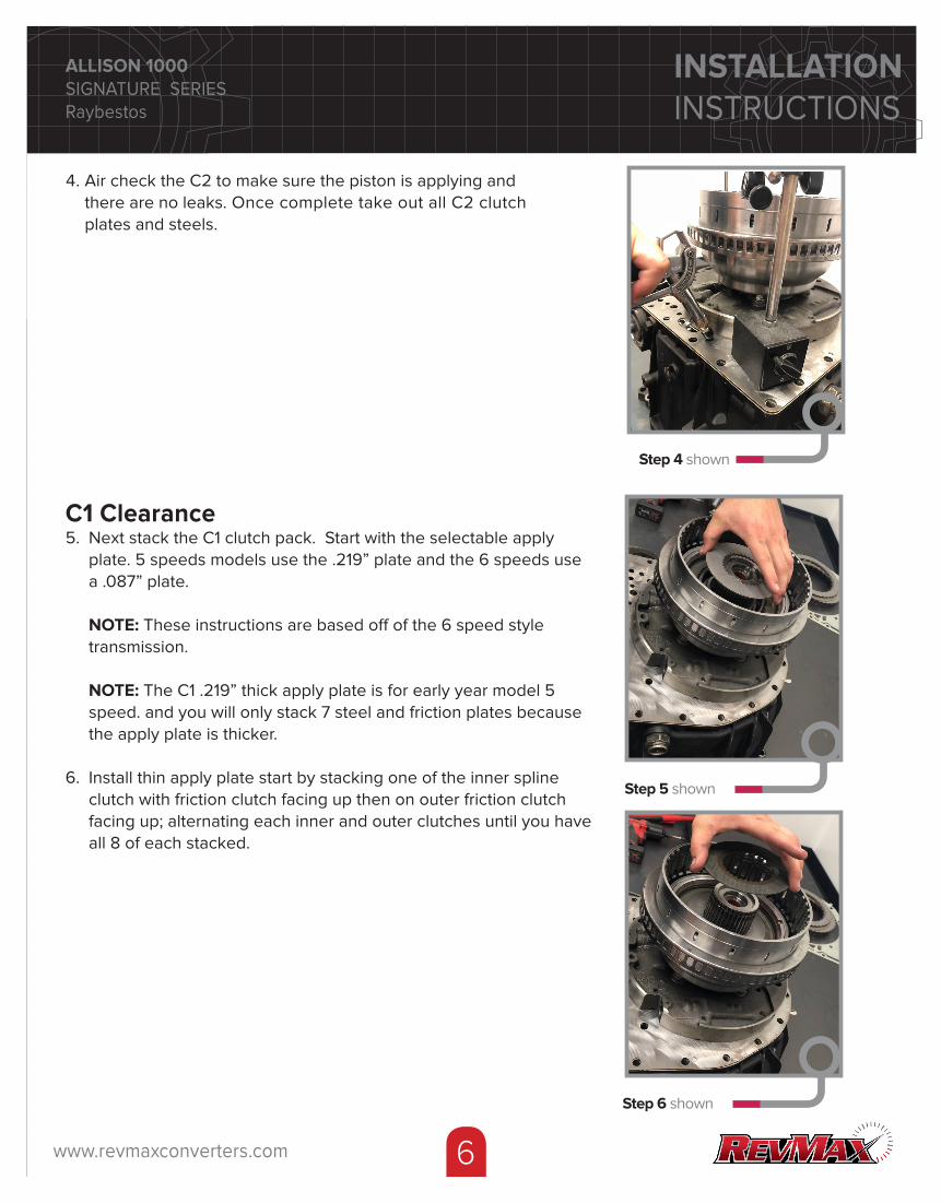
4. Air check the C2 to make sure the piston is applying and there are no leaks. Once complete take out all C2 clutch plates and steels.
Step 4 shown
C1 Clearance5. Next stack the C1 clutch pack. Start with the selectable apply plate. 5 speeds models use the .219” plate and the 6 speeds use a .087” plate. NOTE: These instructions are based off of the 6 speed style transmission. NOTE: The C1 .219” thick apply plate is for early year model 5 speed. and you will only stack 7 steel and friction plates because the apply plate is thicker.
6. Install thin apply plate start by stacking one of the inner spline clutch with friction clutch facing up then on outer friction clutch facing up; alternating each inner and outer clutches until you have all 8 of each stacked.
Step 5 shown
ALLISON 1000SIGNATURE SERIESRaybestos
Step 6 shown

INSTALLATIONINSTRUCTIONS
7www.revmaxconverters.com
7. Add the pressure plate followed by the thick snap ring. Do not Install the spiral snap ring at this time
Step 7 shown
Step 8 shown
C1 and C2 Final Assembly9. Once you have final clearances for C1 & C2 you can start the final assembly. Start with placing the spiral snap ring over the thick snap ring. Then put the thrust bearing on top of your input shaft.
Step 9 shown
ALLISON 1000SIGNATURE SERIESRaybestos
Step 7 shown
Step 9 shown
8. To determine C1 clearance place the dial indicator on the middle of the top plate. Air check the C1 clutch pack with air pressure into indicated hole (See Step 8 photo).
NOTE: The C1 clearance is .105” to .125”.
Dial Indicator Location

INSTALLATIONINSTRUCTIONS
8www.revmaxconverters.com
10. Place the C1 hub. Make sure it is seated properly over all the C1 clutch stack. Place the C1 thrust bearing onto the C1 hub.
Step 10 shown
11. Place the C2 hub on top of the bearing. Next you will restack your C2 clutches starting with a steel and then a friction clutch. Alternating back and forth.
Step 11 shown
12. Install the P1 planetary drive flange and P1 planetary snap ring.
Step 12 shown
ALLISON 1000SIGNATURE SERIESRaybestos
Step 11 shown
INSTALLATIONINSTRUCTIONS
9www.revmaxconverters.com
Step 13 shown
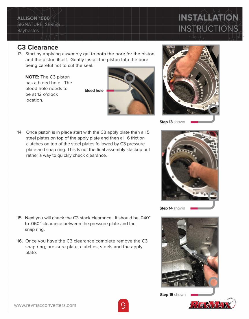
14. Once piston is in place start with the C3 apply plate then all 5 steel plates on top of the apply plate and then all 6 friction clutches on top of the steel plates followed by C3 pressure plate and snap ring. This Is not the final assembly stackup but rather a way to quickly check clearance.
Step 14 shown
15. Next you will check the C3 stack clearance. It should be .040” to .060” clearance between the pressure plate and the snap ring.
16. Once you have the C3 clearance complete remove the C3 snap ring, pressure plate, clutches, steels and the apply plate.
Step 15 shown
ALLISON 1000SIGNATURE SERIESRaybestos
C3 Clearance13. Start by applying assembly gel to both the bore for the piston and the piston itself. Gently install the piston Into the bore being careful not to cut the seal.
NOTE: The C3 piston has a bleed hole. The bleed hole needs to be at 12 o’clock location.
bleed hole

INSTALLATIONINSTRUCTIONS
10www.revmaxconverters.com
C4 Clearance18. Once the piston is in place start with the C4 apply plate followed by all 6 friction clutches. Then place all 5 steel plates on top of the friction clutches. This Is not the final assembly stackup but rather a way to quickly check clearance.
NOTE: The C4 piston has a bleed hole. The bleed hole needs to be at 12 o’clock location.
Step 18 shown
19. Place C4 pressure plate and install snap ring on top.
Step 19 shown
ALLISON 1000SIGNATURE SERIESRaybestos
17. Next you will put the C3 pressure plate back in the case with C3 snap ring. Start by applying assembly gel to both the bore for the piston and the piston itself. Gently Install the piston into the bore being careful not to cut the seal.
bleed hole
INSTALLATIONINSTRUCTIONS
11www.revmaxconverters.com
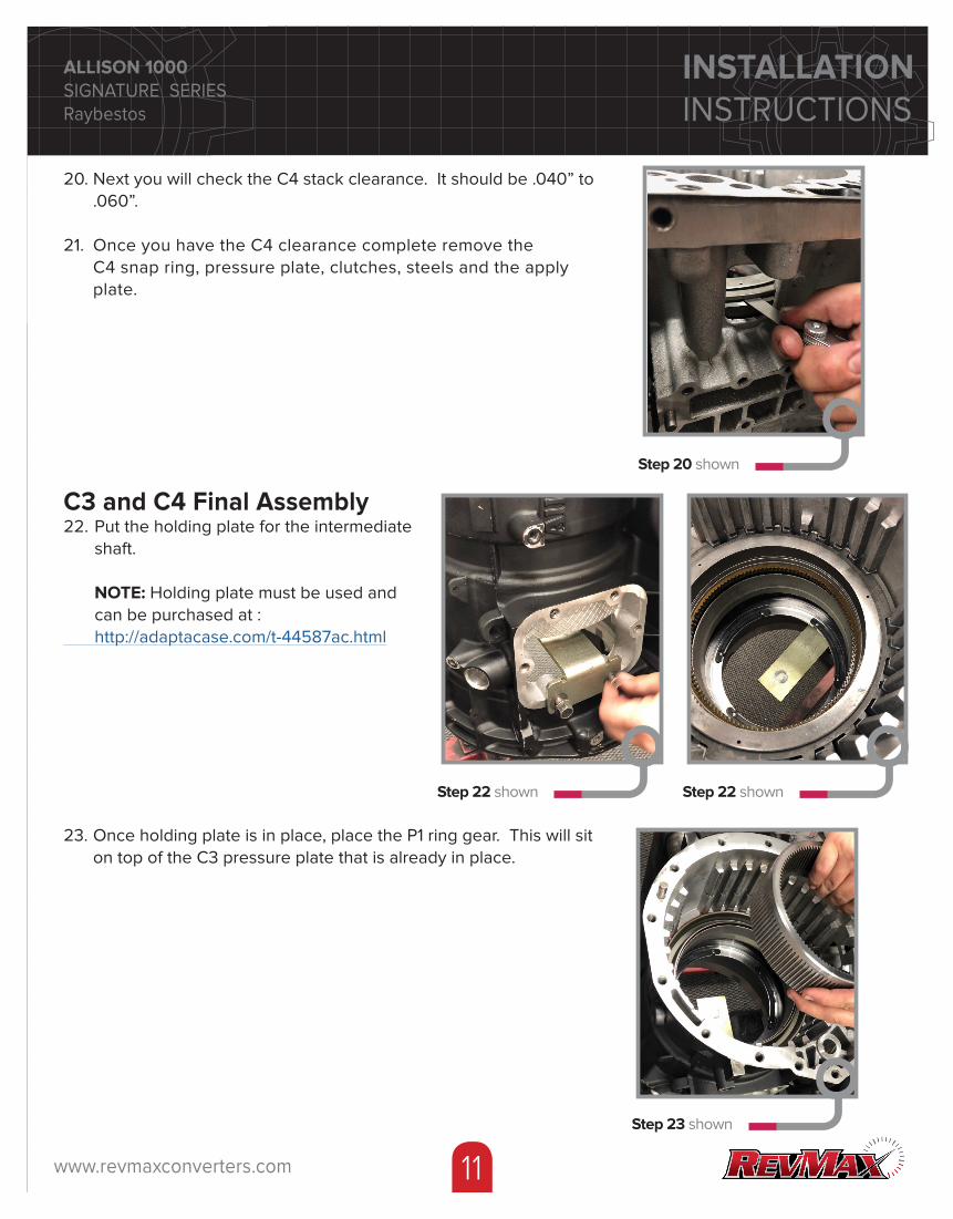
20. Next you will check the C4 stack clearance. It should be .040” to .060”.
21. Once you have the C4 clearance complete remove the C4 snap ring, pressure plate, clutches, steels and the apply plate.
ALLISON 1000SIGNATURE SERIESRaybestos
Step 20 shown
C3 and C4 Final Assembly22. Put the holding plate for the intermediate shaft.
NOTE: Holding plate must be used and can be purchased at : http://adaptacase.com/t-44587ac.html
Step 22 shown
23. Once holding plate is in place, place the P1 ring gear. This will sit on top of the C3 pressure plate that is already in place.
Step 23 shown
Step 22 shown

INSTALLATIONINSTRUCTIONS
12www.revmaxconverters.com
24. Next place P1 spacer that comes with the C3 kit on to the P1 planetary. Then add the P1 factory plastic spacer.
NOTE: Make sure to line up spacer to notches.
Step 24 shown
25. Place the P1 planetary on to the P1 ring gear.
Step 25 shown
Notches
26. Attach the 3 factory return springs to the new apply plate by snapping them into place. Install apply plate with springs while aligning alignment hole to the piston bleed hole.
NOTE: You must line up the 12 o’clock alignment hole to your 12 o’clock piston hole. There is only one area on the apply plate that will line up between the springs.
Step 26 shown
Alignment

INSTALLATIONINSTRUCTIONS
13www.revmaxconverters.com
27. Place the C4 apply plate with return springs attached then 5 steel plates and 6 friction clutches alternating clutch then steel. You will end up with a friction clutch on top. Be sure all friction and steels (oil holes and slots) line up with bleed hole at 12 o’clock in case. (very Important)
28. Next add the C4 pressure plate and the 2 snap rings. The thin snap ring goes first and then the thick snap goes second.
NOTE: C4 always has 2 snap rings. Earlier years have a spiral snap ring and later have a standard upper snap ring.
Step 28 shown
29. Next you will need to compress the C4 pressure plate using a bar tool and a home fabricated tool similiar to the one shown in order to compress the return springs and then install the 2 snap rings into place.
Step 29 shown
30. Place the P1 and P2 planetary thrust bearing. The shoulder should be facing on the inside.
Step 30 shown

INSTALLATIONINSTRUCTIONS
14www.revmaxconverters.com
31. Place your P2 planetary followed by placing the P2 thrust bearing.
Step 31 shown
32. Next put the P2 sun gear on your intermediate shaft and spline it into your P2 planetary.
Step 32 shown
33. Install the P2 spacer. Line the hole on the intermediate shaft to the opening on the spacer.
Step 33 shown
Step 32 shown

INSTALLATIONINSTRUCTIONS
15www.revmaxconverters.com
34. Next place the P3 sun gear over the end of the intermediate shaft.
35. Follow with the P3 thrust bearing
Step 34 shown
36. Install C5 thick pressure plate on top of the C4 pressure plate and snap rings followed by the frictions and steel plates. Alternating starting with the friction plate first
Step 36 shown
37. Next put the factory return spring in the case on top of C5 stack up. Next spline the P3 planetary and the output shaft together and the whole assembly goes down into the C5 ring gear.
38. The P3 planetary and output shaft will sit flush.
Step 37 shown Step 37 shown

INSTALLATIONINSTRUCTIONS
16www.revmaxconverters.com
39. Put the upper shaft spacer with the selective shim on top.
Step 39 shown40. Install the park pawl assembly.
Step 40 shown Step 40 shown Step 40 shown
Step 41 shown
41. Next step is to place the C5 piston into the extension housing. Make sure both the piston housing and piston seals have assembly gel on them.
NOTE: There is only one way that the piston can go into the housing. There is a hole in the housing and slot on the piston that needs to line up.
Notch
Hole

INSTALLATIONINSTRUCTIONS
17www.revmaxconverters.com
42. Place gasket on top of rear of case then add extension housing. Line the dowel pin up on the case to the extension housing hole.
NOTE: The extension housing will not lay flat until you bolt down.
Step 42 shown
43. Put the housing extension bolts in and secure in a star pattern around the extension housing to ensure an even seal.
Step 43 shown
44. Next install the upper shaft blocking nut with the blue seal facing up. You will need to use a special socket which can be purchased at: http//adaptacase.com/t-1000ac.html
Step 44 shown
Step 42 shown

INSTALLATIONINSTRUCTIONS
18www.revmaxconverters.com
45. Flip the case so the extension housing is facing the ground so you can get to your C3 stack up. Remove holding plate that was holding the intermediate shaft.
Step 45 shown
46. Pull out C3 snap ring and pressure plate. Add C3 factory springs to the C3 apply plate and match center hole at 12 o’clock position.
NOTE: The springs will only go proper locations.
47. Start the C3 stack up of steel and friction clutches starting with a steel apply plate with factory return springs then a friction clutch with the bleed hole at 12 o’clock. Alternate with steel and friction clutches. You will end with a friction clutch.
48. Place the C3 pressure plate on top of the C3 stack followed by the snap ring.
Step 46 shown
49. Next you will need to compress the C3 pressure plate using a bar tool and a home fabricated tool similiar to the one shown. Once pressed down you can put in the C3 snap ring.
Step 49 shown

INSTALLATIONINSTRUCTIONS
19www.revmaxconverters.com
50. Next you will add the input drum with your C1 and C2 stacks and place it into the case.
Step 50 shown Step 50 shown
51. To make sure it is fully seated into the P1 planetary.
Step 51 shown
52. Place gasket on case before attaching your pump assembly and bell housing.
Step 52 shown

INSTALLATIONINSTRUCTIONS
20www.revmaxconverters.com
53. Place pump assembly and bell housing onto case.
Step 53 shown
54. Bolt down the housing to the case. Secure in a star pattern around the housing to ensure an even seal.
Step 54 shown

INSTALLATIONINSTRUCTIONS
21www.revmaxconverters.com
1.877.987.59034520 Westinghouse Blvd | Suite B
Charlotte, NC 28273
www.revmaxconverters.com
Step 56 shown
55. Next check your front end play. The best way to do this it to take a screw driver and place it the void underneath where the input drum is resting. Set your dial Indicator on top of the input shaft and pry down to lift the Input drum. Clearance for front end play is .030” to .045”.
Step 55 shown Step 55 shown