Embed Size (px)
Citation preview
Index Page Features & Construction 1-8 Operation ... .... .. .. ........ . .. . . 8-9 Static Tripping System . . 1 0-1 7 Circuit Breaker Data.... .. 14 Ratings Tables .. . . .. ....... . 18-1 9 Outdoor Switchgear .... .. 20
Index Specification Guide Value Orientation ....... .. . Dimensions .... .. ........ ... . Installations ........ ... ...... .
Page 21 -23
23 24-25
26
DESCRIPTION SG l.la ALLIS·C:HALMERS
Compact, Operator-Tailored- Closed door drawout of electrical or manual stored energy operated power circuit breakers and optional integrally mounted breaker lifting device.
Front Access Current Transformers - Mounted on the stationary disconnects in the breaker compart· ment. They are easily replaced when a change i n breaker rat i ng i s required.
"Pyro-Shieltl" Coordinated Insula· tion System - High strength, track· resistant, flame retardant, Fiberglasreinforced polyester insulation, bus supports and moldings provide high momentary short circuit strength. Edge-to-edge bus bar arrangements which incorporate high creepage allowances provide great abi lity to withstand fault current shocks and magnetic stresses.
•
Page 1
June 1 972
Supersedes August, 1 965
Static Overcurrent Trip Devices in· troduce accuracies and field adjust· ment benefits heretofore unavailable with series overcurrent trip devices. Combinations of long time, short time, instantaneous, and ground fault tripping provide optimum distribution system protection. Any de· vice fits a l l LA-series breakers.
Simple Breaker Rating Change -Changes in continuous current or pickup setting can be made over a two and one half to one maximum to minimum range by changing knob settings on trip unit.
Siniplified Field Checking of Static Trip Devices - Function tests may be conducted with a variable voltage transformer and a portable ammeter. A portable test set for complete checking of static trip devices is available, requiring only 115-volt ac power .
www . El
ectric
alPar
tMan
uals
. com

SG l.la Page 2 LOW VOLT AGE METAL-ENCLOSED SWITCHGEAR
AI.US·CHALMERS
Type ME Low Voltage Switchgear Assembly includes a welded steel framework, sheet steel enclosure, individually welded steel breaker compartments, hinged breaker and auxiliary compartment panels, drawout breaker guide rails, position switches, three-phase buswork and
supports, stationary primary and secondary disconnecting devices, ground bus, power and control cable terminal connectors, instruments and relays, control wiring, terminal blocks and instrument transformers.
....... 1 2 3 4 5 8 7 8
9 10 11 12
,, : . · . . Description Meter Compartment (Page 7) Meter Compartment- Inside View (Page 8) Control Wiring (Page 8) Control Circuit Fuses Teflon Coated Guide Rails (Page 4) Stationary Secondary Disconnects (Page 5) Ammeter and 3-Phase Switch (Pag� 7)
. . , ..... . :· · .. , .·.•
LA-1600 Electrically Operated Breaker in "Connected" Position (Page 3, 8, 9) Breaker Escutcheon Opening
224089-5
LA-600 Manually Operated Breaker in "Test" Position (Page 3, 8, 9) Screened Ventilation Openings Compartment for Future Breaker
The information contained herein is general in nature and is not intended far specific construction, installation, or application purposes. Allis-Chalmers reserves the right to make changes in specifications shown herein or add improvements at any time without notice or obligation.
7
8
10
11
12
www . El
ectric
alPar
tMan
uals
. com
SG l.la LOW VOLT AGE METAL-ENCLOSED SWITCHGEAR Page 3
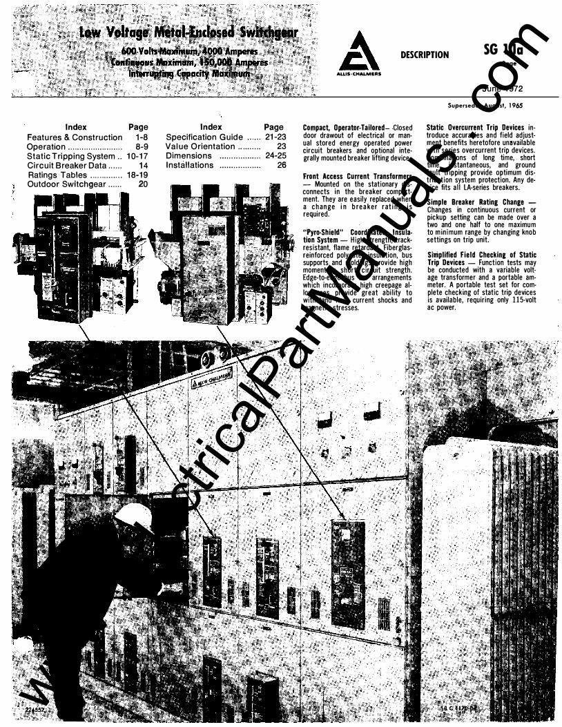
LA-Series Low Voltagr: Power Circu1t Breaker includes a stored energy operating mechanism (either manually or electrically operated), arc quenchers, main and
Legend Description 1 Rating nameplate 2 Contact position indicator 3 Racking mechanism shutter (with
padlocking provisions) 4 Handle stop 5 Stored energy mechanism indicator 6 Handle for manually charging stored
energy springs 7 Contact closing lever 8 Tripping lever (with padlocking provisions) 9 Static Trip n: overcurrent device
The LA Series low voltage power circuit breakers are designed for 600-volt and below service with current carrying capacities up to 4000 amp and interrupting capacities up to 1 50,000 amperes. These compact, flexible, fast operating, dead-front circuit breakers incorporate stored energy for fast, positive closing.
Electrically operated stored energy breakers are closed smoothly and positively by the action of springs that have been precharged by an electric motor. The springs remain charged indefinitely until the breaker is to be closed. When energy is released to close the breaker, the motor automatically recharges the springs for another closing operation.
Manual operated stored energy breakers are charged by one downward stroke of the handle; when handle is released it returns to the normal position. A closing
AlliS-CHALMERS
arcing contact structure, inductive tripping transformers, static overcurrent trip device, control wiring, auxiliary switches, interlocks and position indicators.
Legend Description 10 Inter-phase barriers 11 Arc chutes 12 Clevis attached to racking drive screw 13 Drawout guide rails 14 Secondary disconnects (movable) 15 Auxiliary switch 16 Spring charging motor {electrically operated
breaker only) 17 Breaker position indicators 18 Power switch for spring charging motor
lever, located on the front of the breaker, releases the stored energy to close the breaker.
Stored energy provides a quick make switching mechanism that assures high speed closing of breaker primary contacts, independent of operator. Positive, controlled closing prevents unnecessary arcing between the movable and stationary breaker contacts as would be the case with slow or hesitant manual closing. This prevents the potentially dangerous results of improper closing, thereby lengthening contact and breaker life.
Located on the front of the breaker are the tripping lever, targets which indicate primary contact position and condition of stored energy springs, racking screw shutter, breaker close lever, and - for manual stored energy breakers- the charging handle. www .
Elec
tricalP
artM
anua
ls . c
om
SG l.la Page 4
ALLIS-CHALMERS
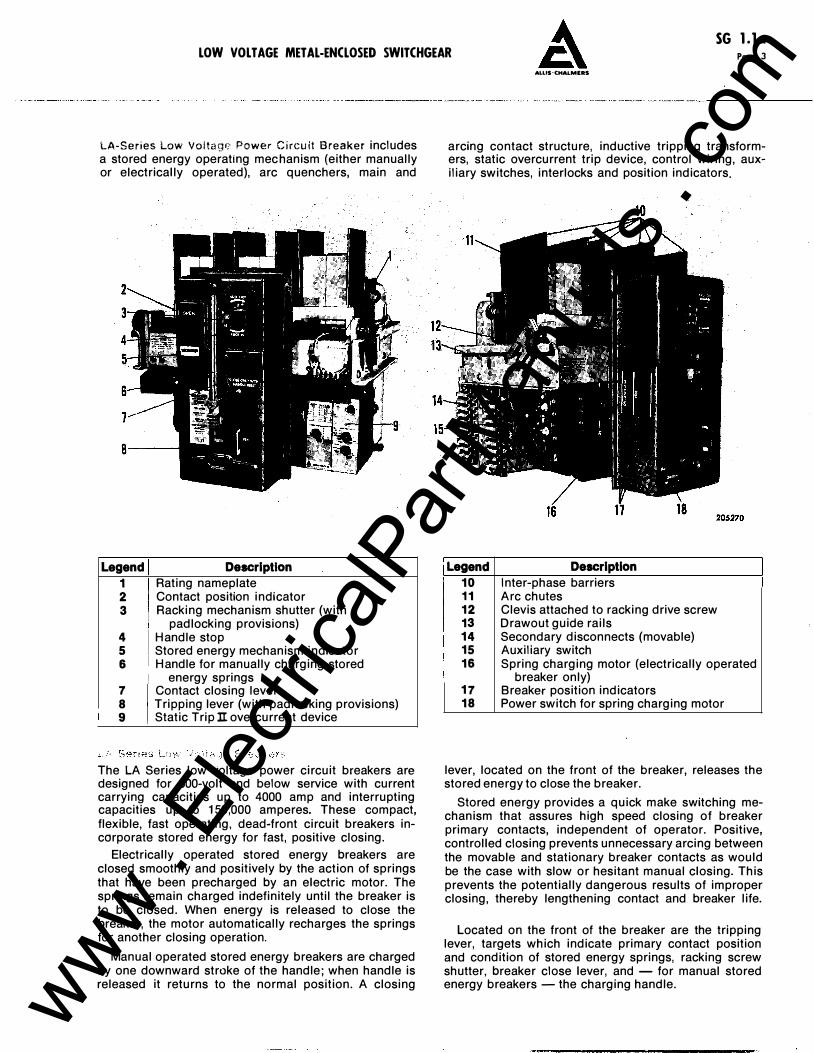
Front Access Current Transformers
Most arrangements have instrument transformers mounted on the stationary primary disconnect studs where they are readily accessible when a feeder circuit change requires replacement of CT's for those of a different rating. No need to enter bus or cable compartment and disturb primary buswork or disconnect cables when replacing CT's.
Teflon Lubricated Breaker Guide Rails
A Teflon coating results in low friction guide rails for ease in removal and insertion of the low voltage power circuit breaker.
Primary Disconnects
LOW VOLT AGE METAL-ENCLOSED SWITCHGEAR
LA-3000 or LA-4000
LA-600 or LA-1600
Primary circuit connections between the removable circuit breaker and the switchgear assembly are made by sets of silver-plated contacts on the circuit breaker with silver-plated stationary contacts in breaker compartment. The finger contacts are mounted on the studs of the circuit breaker, facilitating inspection and maintenance. The stationary contacts are mounted on a solid Pyro-Shield insulation molding which is bolted to the rear wall of the breaker cubicle. Design of movable primary disconnects.
Primary discon necting devices are arranged so that contact is made only when the removable circuit breaker is in the operating or "connected" position . In the "test" position the primary contacts are separated
Firm contact pressure is maintained by means of spring-steel back-up springs. As the circuit breaker is moved into the operating position, the wiping action of the self-aligning co11tacts assures low contact resis
by a safe distance. LA·600 or LA-1600 tance. LA-3000 or LA-4000
1. Key Interlock 4. Teflon Lubricated Guide Rails 7. Stationary Secondary Disconnects 2. Front Access current Transformers s. Breaker Drawout Stop 8. Breaker Ground Contact 3. Stationary Primary Connections 6. Pyro-Shield Primary Disconnect 9. Safety Interlock
Support Molding
To prevent accidental contact with live parts, molded PVC boots are used to cover the primary contacts of cubicles arranged for future addition of breakers.
23036$
www . El
ectric
alPar
tMan
uals
. com
SG l.la LOW VOLT AGE METAL-ENCLOSED SWITCHGEAR A Page 5
Secondary Disconnects Control of secondary circuit connections between the circuit breaker and stationary switchgear structure are made by means of automatic, self-aligning, multi-contact, silver plated, slip-type connectors.
The contact surfaces in the stationary element· are heavily silver plated copper strips and mounted on a sturdy molded base of Pyro-Shield insulation. These contact surfaces are recessed to properly guide the movable fingers and to prevent accidental short-circuiting of the control circuits.
The movable secondary disconnect elements are located on the lower left side of the low voltage power circuit breaker, well below the arc quenching area to avoid contamination from rapidly rising arc product gases. With the panel door open, the engagement of the secondary disconnecting elements is clearly visible to the operator.
The secondary connections make contact when the breaker is in both the "test" and "connected" positions.
lotio ... _ ..
100:5 150:5 200:5 250:5 300:5 400:5 500:5 600:5 800:5
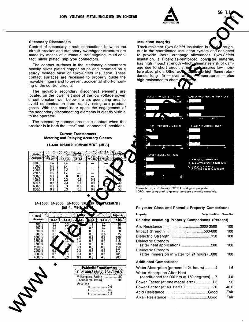
Current Transformers Metering and Relaying Accuracy Classes
LA-600 BREAKER COMPARTMENT (ME-3)
0.6 0.6 0.6 0.6 0.6 0.6 0.6 0.3 0.6 0.6
10 10 15 15 20 25 30 40 50
LA-1600, LA-3000, LA-4000 BREAKER COMPARTMENTS (ME-4, ME-5, ME-6)
Ratio l!lfll .. · .,"'"'"• Am..-ret 8..0.1 1-0.2 a..o.s l•l.O 1-2.0 IOC
400:5 0.3 0.3 0.6 1.2 1.2 40 500:5 0.3 0.3 0.3 0.6 1.2 50 600:5 0.3 0.3 0.3 0.6 1.2 60 800:5 0.3 0.3 0.3 0.6 0.6 75
1000:5 0.3 0.3 0.3 0.3 0.3 100' 1200:5 0.3 0.3 0.3 0.3 0.3 115 1500:5 0.3 0.3 0.3 0.3 0.3 130 2000:5 0.3 0.3 0.3 0.3 0.3 150 2500:5 0.3 0.3 0.3 0.3 0.3 170 3000:5 0.3 0.3 0.3 0.3 0.3 185 4000:5 0.3 0.3 0.3 0.3 •. 3 200
Potential Trcmsforntel'$ 1 0 480/UOV,288/l20V Voltampere Rating ................ 100 Thermal VA Rating ................ 500 Accuracy
w .................. 0.6 X .................... 0.6 y ................ .... 1.2
AlLIS· CHALMERS
Insulation Integrity
Track-resistant Pyro-Shield insulation is used throughout in the coordinated insulation system and designed to provide liberal creepage allowances. Pyro-Shield insulation, a Fiberglas-reinforced polyester material, has high impact strength which eliminates risk of damage due to short circuit stress and assures low moisture absorption. Other advantages are high flame retardance, long life - even at high temperatures - plus high resistance to chemical fumes.
Characteristics of phenolic "X" F.R. and glass polyester "GPO" are compared to general purpose phenolic materials.
Polyester-Glass and Phenolic Property Comparisons
Property Polyester-Glass Phenolics Relative Insulating Property Comparisons (Percent)
Arc Resistance ................... ....... . .... ..... 2000-2500 100 Impact Strength .... ...... . ..... ... . . .......... ..... 500-600 100 Dielectric Strength ............. ... . ............ . ....... ... 1 50 100 Dielectric Strength
(after heat application) ......... . . . . . ... ............. 200 100 Dielectric Strength
(after immersion in water for 24 hours) .. 600 100
Additional Comparisons
Water Absorption (percent in 24 hours) ......... .4 Water Absorption After Heat
(conditioned for 200 hrs at 150 degrees) .... 7 Power Factor (at one megaHertz) ................ 1.5 Power Factor (at 60 Hertz ) .. ........................ 2.0 Acid Resistance . . . . . . ..... . . . . . . . . . ......... .. . . . ... . . ... Good
1.6
4.0 7.0
40.0 Fair
Alkali Resistance .. . . ...... ... ..... .... ..... ... ...... . .. . Good Fair
www . El
ectric
alPar
tMan
uals
. com
SG l.la Page 6
ALUS-CHALMERS
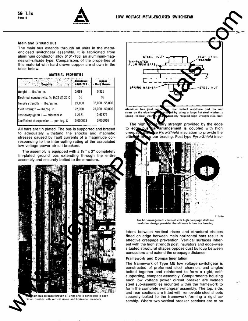
Main and Ground Bus The main bus extends through all units in the metalenclosed switchgear assembly. It is fabricated from aluminum conductor alloy 6101-T63, an aluminum-magnesium-silicide type. Comparisons of the properties of this material with hard drawn copper are shown in the table below.
MATERIAL PROPERTIES
AlumlnuJII Copper Preperty 6l0J.T63 Hard Dr-n
Weight- lbs/cu. in . 0.098 0.321
Electrici!l conductivity, % lACS @ 20 C 56 98
Tensile strength- lbs/sq. in. 27,000 35,000- 55,000
Yield strength- lbs/sq. in. 22,000 25,000. 50,000
Resistivity@ 20 C- microhm in. 1.2121 0.67879
Coefficient of expansion - per deg. C 0.000023 0.000016
All bars are tin plated. The bus is supported and braced to adequately withstand the shocks and magnetic stresses caused by fault currents of a magnitude corresponding to the interrupting rating of the associated low voltage power circuit breakers.
The assembly is equipped with a V4" x 3" completely tin-plated ground bus extending through the entire assembly and securely bolted to the structure.
The main bus extends through all units and is connected to each
circuit breaker with vertical risers and horizontal members.
LOW VOLT AGE MET At-ENCLOSED SWITCHGEAR
STEEL BOLT-�"'="-"="'"' TIN-PLATED ALUMINUM BARS t--..��c====L-�
Aluminum bus joint connection. Low contact resistance and low unit stress on the aluminum are assured by using a large flat steel washer, a spring (conical) washer, and o properly torqued high strength steel bolt.
The high momentary strength provided by the edge to edge bus bar arrangement is coupled with high creepage distance Pyro-Shield insu lation to provide the ultimate in bus bar bracing. Post type Pyro-Shietd insu-
Bus bor arrangement coupled with high creepage distance insulation design provides the ultimate in bus bar bracing.
215486
lators between vertical risers and structural shapes fitted on edge between main horizontal bars result in effective creepage prevention. Vertical surfaces inher· ent with the high strength post insulators and edge-wise situated structural shapes oppose dust buildup between conductors and extend the creepage distance.
Framework and C ompartmentation
The framework of Type ME low voltage switchgear is constructed of preformed steel channels and angles bolted together and reinforced to form a rigid, selfsupporting, compact assembly. Compartments housing each low voltage power circuit breaker are welded steel sub-assemblies mounted within the framework to form the complete switchgear assembly. The top, side, and rear sections are fitted with removable steel sheets securely bolted to the framework forming a rigid assembly. Where two vertical breaker sections are to be www .
Elec
tricalP
artM
anua
ls . c
om
SG l.la LOW VOLT AGE METAL-ENCLOSED SWITCHGEAR Page 7
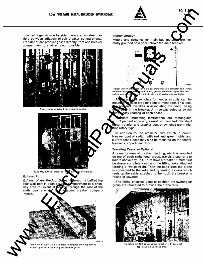
mounted together side by side, there are two steel barriers between adjacent circuit breaker compartments. Transfer of arc product gases directly from one breaker compartment to another is not possible.
Ample space provided for incoming cables.
Type ME, 600-volt metal enclosed switchgear cubicles.
Exhaust Port
Exhaust of Arc Product Gases is through a baffled top rear wall port in each breaker compartment to a chimney area for eventual venting through the roof of the switchgear and not into adjacent breaker compartments.
223393-B Top view of Type ME low voltage switchgear showing baffled exhaust part for exhausting arc product gases.
AUIS-CHALMEAS
Instrumentation
Meters and switches for main bus metering are normally grouped on a panel above the main breaker.
( { (
• • •
' 223348
Typical instrument panel for main bus metering with ammeter and switch, watthour meter, voltmeter and switch, ground detection lights with test switch, and circuit breaker control switch with red and green lights.
Ammeters and switches for feeder circuits can be mounted on each breaker compartment door. This location prevents mistakes in associating the circuit being metered with the breaker. A three-way selector switch allows easy reading of each phase.
Standard indicating instruments are rectangular, with 2 percent accuracy, semi-flush mounted. Standard meter transfer and breaker control switches are miniature rotary type.
In addition to the ammeter and switch, a circuit breaker control switch with red and green lights and current test blocks may also be mounted on the feeder breaker compartment door.
Traveling Crane - Optional
A crane for ease of breaker handling, which is mounted on top of each switchgear group, travels along rails to locate above any unit. To remove a breaker it must first be drawn completely out and the lifting yoke attached forming a two point lift. Then the hook from the crane is connected to the yoke and by turning a crank which reels up the cable attached to the hook, the breaker is raised or lowered.
The lifting channels used to position the switchgear group are relocated to provide the crane rails.
Handling LA-600 power circuit breaker with optional top-mounted traveling crane. www .
Elec
tricalP
artM
anua
ls . c
om
SG l.la Page 8
AI.LIS-CHALMEAS
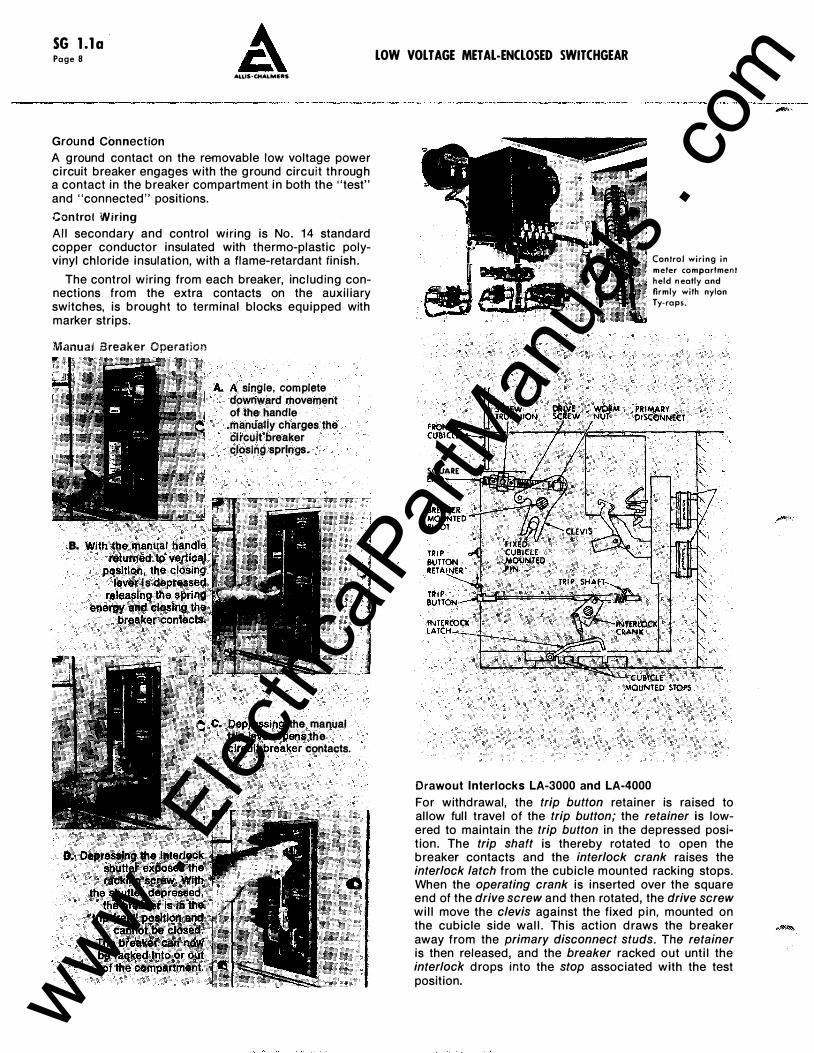
Ground Connect ion A ground contact on the removable low voltage power circuit breaker engages with the ground circuit through a contact in the breaker compartment in both the "test" and "connected" positions.
Control Wiring All secondary and control wmng is No. 1 4 standard copper conductor insulated with thermo-plastic polyvinyl chloride insulation, with a flame-retardant finish.
The control wiring from each breaker, including connections from the extra contacts on the auxiliary switches, is brought to terminal blocks equipped with marker strips.
Manual Breaker Operation
a. With the manual handle retumed to vertical
poalti4n, the closing lever is depressed
releaalng .the spring energy �np closing ctft�
.btfpaker·contac;ts�
A. A single, complete . downward movement
of the handle .manually charges the circuit breaker closing springs.
C. Depressing the manual trip lever opens the eircuirbreaker contacts.
LOW VOLT AGE METAL-ENCLOSED SWITCHGEAR
SQUARE ENO--oodl!ir.l
Control wiring in meter compartment held neatly and firmly with nylon Ty-raps.
!)R'IV! WORM PRIMAR'I' SCII:!W. NUT OtSCoNNECT
Drawout Interlocks LA-3000 and LA-4000
For withdrawal, the trip button retainer is raised to allow full travel of the trip button; the retainer is lowered to maintain the trip button in the depressed position. The trip shaft is thereby rotated to open the breaker contacts and the interlock crank raises the interlock latch from the cubicle mounted racking stops. When the operating crank is inserted over the square end of the drive screw and then rotated, the drive screw will move the clevis against the fixed pin, mounted on the cubicle side wall. This action draws the breaker away from the primary disconnect studs. The retainer is then released, and the breaker racked out until the interlock drops into the stop associated with the test position. www .
Elec
tricalP
artM
anua
ls . c
om
SG l.la LOW VOLT AGE METAL-ENCLOSED SWITCHGEAR A Page 9
Dr awou', Interlocks lA-ciOO and LA· i 60L
CiNECTED
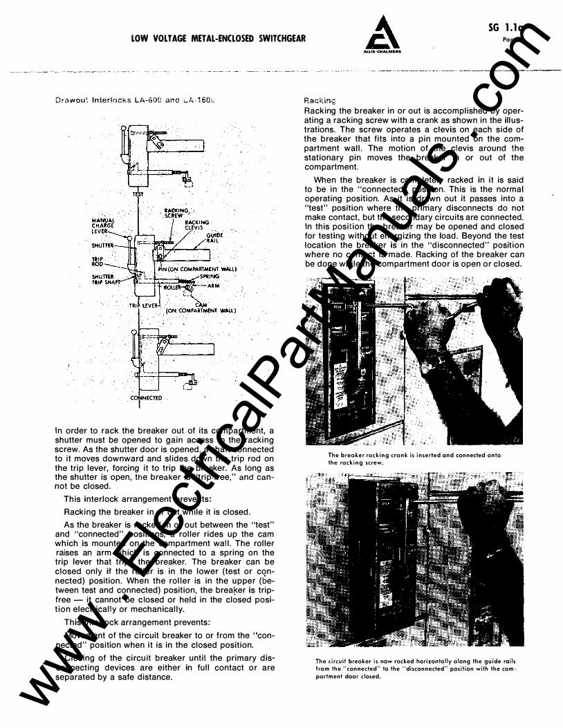
In order to rack the breaker out of its compartment, a shutter must be opened to gain access to the racking screw. As the shutter door is opened, a shaft connected to it moves downward and slides down the trip rod on the trip lever, forcing it to trip the breaker. As long as the shutter is open, the breaker is "trip·free," and cannot be closed.
This interlock arrangement prevents:
Racking the breaker in or out while it is closed.
As the breaker is racked in or out between the "test" and "connected" positions, a roller rides up the cam which is mounted on the compartment wall. The roller raises an arm which is connected to a spring on the trip lever that trips the breaker. The breaker can be closed only if the roller is in the lower (test or connected) position. When the roller is in the upper (between test and connected) position, the brea�er is tripfree- it cannot be c losed or held in the closed position electrically or mechanically.
This interlock arrangement prevents:
Movement of the circuit breaker to or from the "connected" position when it is in the closed position.
Closing of the circuit breaker until the primary disconnecting devices are either in full contact or are separated by a safe distance.
ALLIS-CHALMERS
Racking Racking the breaker in or out is accomplished by operating a racking screw with a crank as shown in the illustrations. The screw operates a clevis on each side of the breaker that fits into a pin mounted on the compartment wall. The motion of the clevis around the stationary pin moves the breaker in or out of the compartment.
When the breaker is completely racked in it is said to be in· the "connected" position. This is the normal operating position. As it is drawn out it passes into a "test" position where the primary disconnects do not make contact, but the secondary circuits are connected. In this position the breaker may be opened and closed for testing without energizing the load. Beyond the test location the breaker is in the "disconnected" position where no contact is made. Racking of the breaker can be done while the compartment door is open or closed.
The breaker racking crank is inserted and connected onto the racking screw.
The circuit breaker is now racked horizontally along the guide rails from the "connected'' to the "disconnected" position with the com· partment door closed. www .
Elec
tricalP
artM
anua
ls . c
om
SG l.la Page 10 LOW VOLT AGE METAL-ENCLOSED SWITCHGEAR
ALLIS-CHALMERS
STATIC OVERCURRt:NT TRIPPING SYSTEM
Static overcurrent tripping has been standard on the LA line of circuit breakers since 1 962. The tripping system was re-designed in 1 971 to make use of the latest integrated circuit components and is called Static Trip 1f.
The Static Trip II system provides the following features:
Ease and accuracy in making field adjustments.
Excellent repeatability.
Negligible change in characteristics with normal temperature variations. Continuous pick-up adjustment over a wide range -no taps to change. Ground current tripping available without an external relay.
Simple field testing without need of a primary current source - portable test set available as an option.
Minimum maintenance - only one moving part.
Simple breaker rating change.
Flexibility - many combinations available including long time delay, short time delay, instantaneous and ground fault elements in the same device.
The tripping system is completely contained on the circuit breaker. The power for tripping the breaker and for operating the solid state circuitry in the static trip device is drawn from the primary current through tripping current transformers mounted on the breaker. Four-wire ground applications include a fourth current transformer mounted in the cable compartment. A signal, proportional to primary current, is taken from these same tripping transformers. This signal is applied to the static trip device and causes it to operate the
tripping actuator to trip the breaker in accordance with a pre-set time delay versus current magnitude relationship.
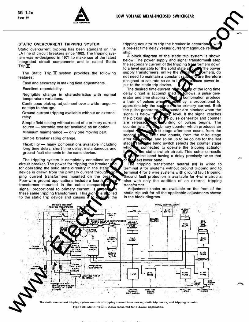
A block diagram of the static trip system is shown below. The power supply and signal transformers step the secondary current of the tripping transformers down to a level suitable for the solid state circuits. The power supply transformers, unlike the signal transformers, do not need to maintain a constant ratio and are therefore designed to saturate so as to limit maximum power input to the static trip device.
The desired time-current relationship of the long time delay circuit is accomplished as follows: a pulse generator and time shaping circuit in combination produce a train of pulses whose frequency is proportional to approximately the square of the primary current. Both the pulse generator and counter are blocked when the signal is below the pickup level. If the signal reaches the pickup level, both the pulse generator and counter are released, and counting of pulses begins. The counter is a 7-stage binary counter which produces an output from the first stage after one count, from the second stage after two counts, from the third stage after four counts, and so on up to 64 counts for the last stage. The time band switch sel.ects the counter stage which is connected to operate the tripping actuator through the static switch circuit. This scheme resulls in each time band having a delay precisely twice that of the next lower band.
The tripping transformer neutral (N) is wired to terminal 9 for systems without ground tripping and to terminal 4 for 3 wire systems with ground fault tripping. Ground fault protection is available for 4-wire circuits also with only the addition of an external tripping transformer.
Adjustment knobs are available on the front of the static trip unit for all the applicable adjustments shown in the block diagram.
I.OHG TIME LONG TIM£ CURRENT• P«:KUP
TIME SHAPING CIRCUIT
JtfSTANTAN£0US CIRCUIT
The static overcurrent tripping system consists of tripping current transformers, stotic trip device, and tripping actuator.
Type TSIG Static TripJI is shown connected for a 3-wire application.
-
www . El
ectric
alPar
tMan
uals
. com
LOW VOLTAGE METAL-ENCLOSED SWITCHGEAR
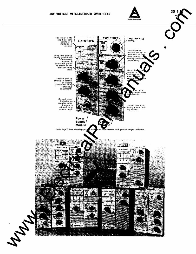
Time delay of the long time band
setting at 6 multiples of
pick-up.
Long time pick-up setting (continuous
adjustment). Current at
calibration points is shown on the
breaker rating plate.
Ground pick-up setting in percent
of tripping transformer rating
(continuous adjustment).
Ground target indicator
operates when tripping is
initiated by a ground fault.
Power / Supply Module
ALUS·CHALMERS
Instantaneous pick-up setting in �t:";llftmrmiiir'Miitnr-:J..- mu IIi p 1 es of 1 o ng II time pick-up setting (continuous adjustment).
Short time pick-up setting in multiples of long time pick-up setting (continuous adjustment).
Static Trip 1I face showing pickup and band adjustments and ground target indicator.
SG l.la Page 11
www . El
ectric
alPar
tMan
uals
. com
SG l.la
Page 12 ALLIS-CHALMERS
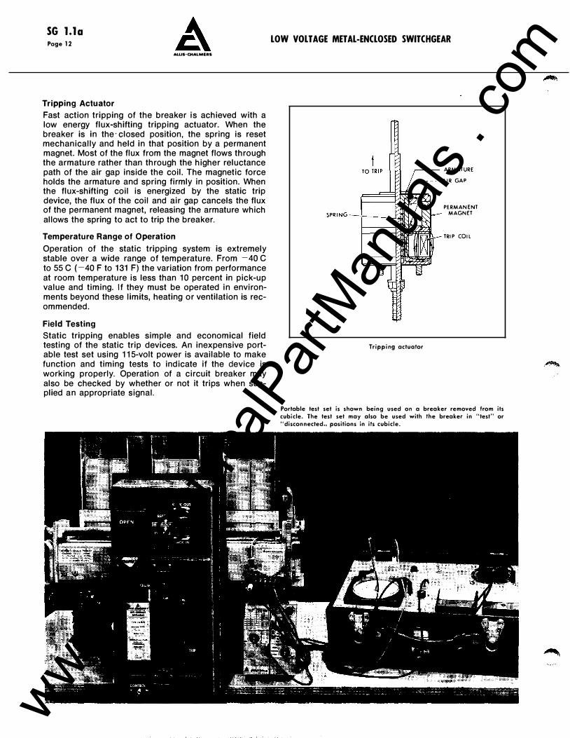
Tripping Actuator
Fast action tripping of the breaker is achieved with a low energy flux-shifting tripping actuator. When the breaker is in the· closed position, the spring is reset mechanically and held in that position by a permanent magnet. Most of the flux from the magnet flows through the armature rather than through the higher reluctance path of the air gap inside the coil. The magnetic force holds the armature and spring firmly in position. When the flux-shifting coil is energized by the static trip device, the flux of the coil and air gap cancels the flux of the permanent magnet, releasing the armature which allows the spring to act to trip the breaker.
Temperature Range of Operation
Operation of the static tripping system is extremely stable over a wide range of temperature. From -40 C to 55 C (-40 F to 1 31 F) the variation from performance at room temperature is less than 1 0 percent in pick-up value and timing. If they must be operated in environments beyond these limits, heating or ventilation is recommended.
Field Testing
Static tripping enables simple and economical field testing of the static trip devices. An inexpensive portable test set using 1 1 5-volt power is available to make function and timing tests to indicate if the device is working properly. Operation of a circuit breaker may also be checked by whether or not it trips when supplied an appropriate signal.
LOW VOLTAGE METAL-ENCLOSED SWITCHGEAR
Tripping actuator
ARMATURE
AIR GAP
PERMANENT MAGNET
TRIP COIL
Portable test set is shown being used on a breaker removed from its cubicle. The test set may also be used with the breaker in "test" or "disconnected" positions in its cubicle.
www . El
ectric
alPar
tMan
uals
. com
SG l.la
Page 1 4 ALLIS-CHALMERS
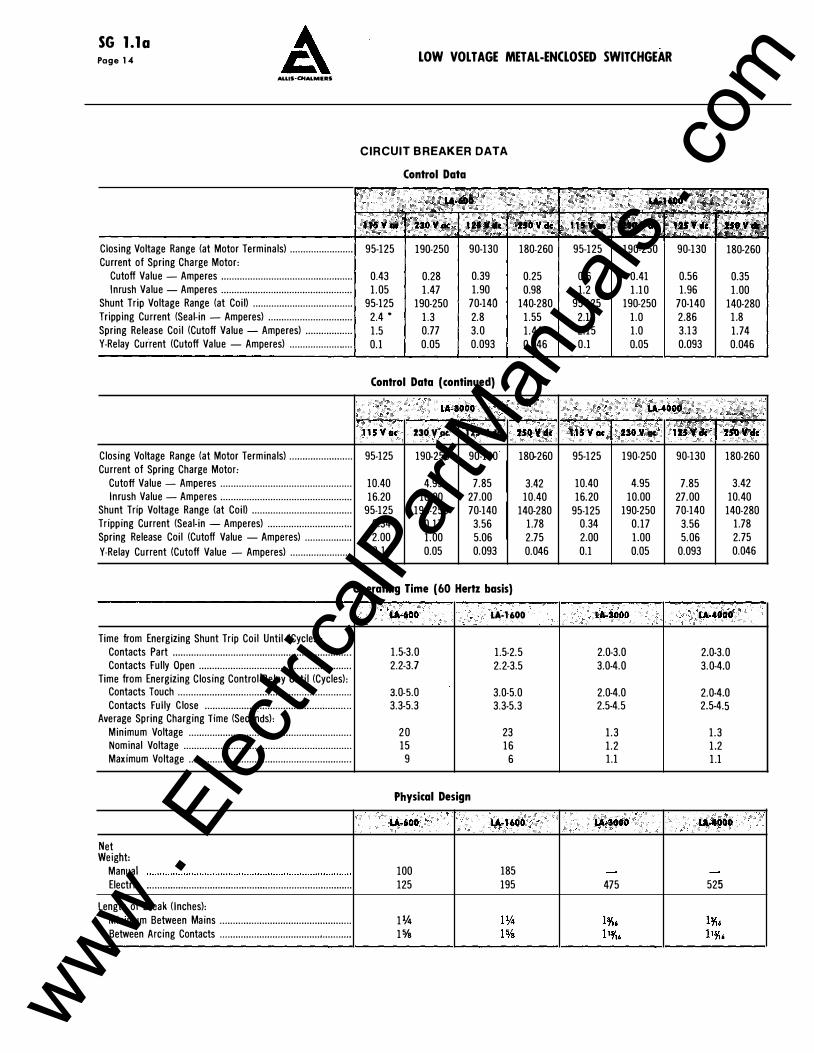
Closing Voltage Range (at Motor Terminals) ........................
Current of Spring Charge Motor:
Cutoff Value - Amperes .................................................. Inrush Value - Amperes ..................................................
Shunt Trip Voltage Range (at Coil) ......................................
Tripping Current (Seal-in - Amperes) ................................
Spring Release Coil (Cutoff Value -Amperes) .................. Y-Relay Current (Cutoff Value -Amperes) ........................
Closing Voltage Range (at Motor Terminals) ........................ Current of Spring Charge Motor:
Cutoff Value - Amperes .................................................. Inrush Value- Amperes ..................................................
Shunt Trip Voltage Range (at Coil) ......................................
Tripping Current (Seal-in -Amperes) ............................. , .. Spring Release Coil (Cutoff Value -Amperes) ..................
Y-Relay Current (Cutoff Value - Amperes) .......................
Time from Energizing Shunt Trip Coil Until (Cycles): Contacts Part ................................................................... . Contacts Fully Open ........................................................ ..
Time from Energizing Closing Control Relay Until (Cycles): Contacts Touch ................................................................. . Contacts Fully Close ...................................................... ..
Average Spring Charging Time (Seconds):
Minimum Voltage ............................................................. . Nominal Voltage ............................................................... . Maximum Voltage ............................................................. .
Net Weight:
Manual
Electric ............................................................................. .
Length of Break (Inches):
Minimum Between Mains ................................................ .. Between Arcing Contacts ................................................. .
LOW VOLTAGE METAL-ENCLOSED SWITCHGEAR
CIRCUIT BREAKER DATA
Control Data
95-125 190-250 90-130 180-260
0.43 0.28 0.39 0.25 1.05 1.47 1.90 0.98
95-125 190-250 70-140 140-280 2.4. 1.3 2.8 1.55 1.5 0.77 3.0 1.44 0.1 0.05 0.093 0.046
Control Data (continued)
u.seoo ·.··• t15Voc 230V C1C 121 v ell: 2SOV4c
95-125 190-250 90-130 180-260
10.40 4.95 7.85 3.42 16.20 10.00 27.00 10.40
95-125 190-250 70-140 140-280 0.34 0.17 3.56 1.78 2.00 1.00 5.06 2.75 0.1 0.05 0.093 0.046
Operating Time (60 Hertz basis)
1.5-3.0 2.2-3.7
3.0-5.0 3.3-5.3
20 15
9
Physical Design
lA·600
100 125
11fil 15/s
lA·l600
1.5-2.5 2.2-3.5
3.0-5.0 3.3-5.3
23 16
6
lA·16tO
185 195
95-125 190-250 90-130 180-260
0.6 0.41 0.56 0.35 1.2 1.10 1.96 1.00
95-125 190-250 70-140 140-280 2.1 1.0 2.86 1.8 2.15 1.0 3.13 1.74 0.1 0.05 0.093 0.046
· �··•· . : .. �:·,E .fi2s�· .. , :.••• ... usvoc 2SOV CIC
95-125 190-250
10.40 4.95 16.20 10.00
95-125 190-250 0.34 2.00 0.1
2.0-3.0 3.0-4.0
2.0-4.0 2.5-4.5
1.3 1.2 1.1
475
0.17 1.00 0.05
·.� .. . � ;fftpj.
90-130 180-260
7.85 3.42 27.00 10.40 70-140 140-280
3.56 1.78 5.06 2.75
0.093 0.046
f.A.4000
2.0-3.0 3.0-4.0
2.0-4.0 2.5-4.5
1.3 1.2 1.1
525
www . El
ectric
alPar
tMan
uals
. com
SG l.lo Page 1 5
LOW VOLT AGE METAL-ENCLOSED SWITCHGEAR
ALUS·CHALMERS
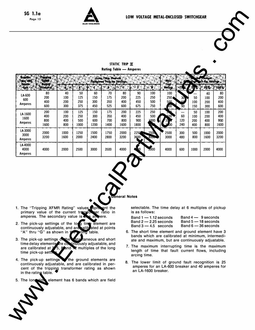
STATIC TRIP :n: Rating Table - Amperes
lA-600 80 40 50 60 70 80 90 100 100 40 80
600 200 100 125 150 175 200 225 250 250 30 50 100 200
Amperes 400 200 250 300 350 400 450 500 500 60 100 200 400 600 300 375 450 525 600 675 750 600 90 150 300 600
lA-1600 200 100 125 150 175 200 225 250 250 50 100 200
1600 400 200 250 300 350 400 450 500 500 60 100 200 400
Amperes 800 400 500 600 700 800 900 1000 1000 120 200 400 BOD
1600 800 1000 1200 1400 1600 1800 2000 1600 240 400 800 1600
lA-3000 2000 1000 1250 1500 1750 2000 2250 2500 2500 300 500 1000 2000
3000 Amperes
3200 1600 2000 2400 2800 3200 3600 4000 3000 480 800 1600 3200
lA-4000 4000 4000 2000 2500 3000 3500 4000 4500 5000 4000 600 1000 2000 4000
Amperes
General Notes
1 . The "Tripping XFMR Rating" values represent the primary value of the current transformer ratio in amperes. The secondary value is one ampere.
2. The pick-up settings of the long time element are continuously adjustable, and are calibrated at points "A" thru "G" as shown in the rating table.
3. The pick-up settings of the instantaneous and short time delay elements are continuously adjustable, and are calibrated at 3, 5, 8 and 1 2 multiples of the long time pick-up setting.
4. The pick-up settings of the ground elements are continuously adjustable, and are calibrated in percent of the tripping transformer rating as shown in the rating table.
5. The long time element has 6 bands which are field
selectable. The time delay at 6 multiples of pickup is as follows:
Band 1 - 1. 1 2 seconds Band 2- 2.25 seconds Band 3- 4.5 seconds
Band 4 - 9 seconds Band 5 - 1 8 seconds Band 6- 36 seconds
6. The short time element and ground element have 3 bands which are calibrated at minimum, intermediate and maximum, but are continuously adjustable.
7. The maximum interrupting time is the maximum length of time that fault current flows, including arcing time.
8. The lower limit of ground fault recognition is 25 amperes for an LA-600 breaker and 40 amperes for an LA-1 600 breaker.
www . El
ectric
alPar
tMan
uals
. com

LOW VOLT AGE METAL-ENCLOSED SWITCHGEAR
Simplified Breaker Rating Change
The continuous rating of the circuit breaker may be readily changed in the field by replacing the tripping current transformers mounted on the circuit breaker studs. The CT rating, listed in primary amperes, will be found on the rating plate of each circuit breaker. Whenever a breaker rating is changed, a new rating plate is furnished.
Current transformers send secondary low voltage signal to trip device proportional to primary current.
Typical Breaker Rating Plate
SERIAL NO. ------TRIPPIIIG XFMR RATIIIG .lA LONG T•E PICI·UP II AMPERES A---
o __ _
G---
WIRED PER MILWAUKEE. WIS. MAO£ IN USA
I C---E F---MAX.COIT. CURRENT ---
A CONTROUI
Ground Target Indicator (Optional)
Trip devices which are provided for sensitive ground fault protection can be furnished with a ground target indicator. This unique device gives a visual indication of a trip initiated by a ground fault. A red button pops out of the face of the trip device when a ground fault causes a breaker to trip. It is reset by simply depressing the red button.
SG l.la Page 13
MUS-CHALMERS
Trip Device Accessibility
Located in the lower right side of the breaker compartment, the trip device is easily accessible to the operator for simple adjustment of all settings.
Plug-in lest points on front of trip device allow testing in the breaker "test" position.
www . El
ectric
alPar
tMan
uals
. com
SG l.la
Page 16
1000 800 600
400
200
100 80 60
40
20
10 8
:g 6 z 0 lil 4 V>
I
.8
.6
A
2
I
.0 8 .0 6
.04
.0 2
.0 I
LOW VOLTAGE METAL-ENCLOSED SWITCHGEAR
ALLIS·CHALMERS
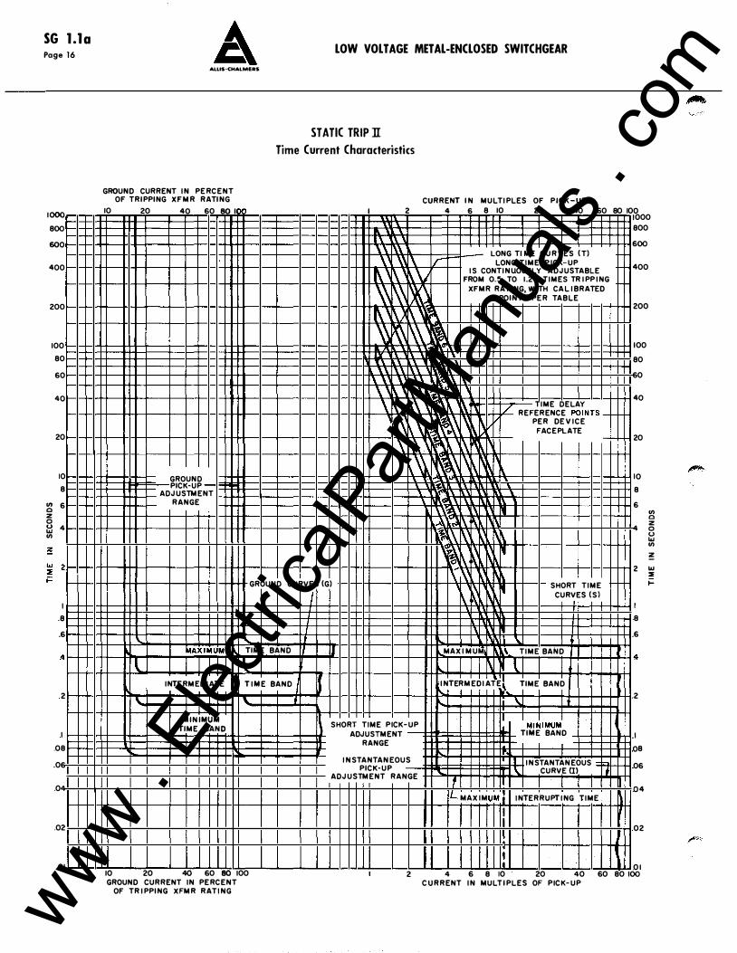
STATIC TRIP ll Time Current Characteristics
GROUND CURRENT IN PERCENT OF T RIPPING XFMR RATING
10 20 40 60 80 I
GROUND PICK-UP
ADJUSTMENT RANGE
I
1\ 1\ \\ \
1\' .� 1\' \� � 1:\ \\
1\\ \' \
CURRENT IN MULTIPLES OF PICK-UP 2 4 6 8 10 20 40 60 80 10 0 000
\ � _l _l l _l _l _l
!\\ LONG Tl ME CUR VES (T) .. � \ r: LONG TIME PICK-UP
�' �'v IS CONTINUOUSLY AD JUSTABLE FROM 0.5 TO 1.25 TIMES TRIPPING
� I� XFMR RATING, WITH CALIBRATED POINTS PER TABLE
� l\ � :\ � 1\\ � ,\ 1
1\\ 1\\ _\ \\ �\ 1\ [\' 1\� � ' 1\\ r\\' � �n / TIME DELAY
REFERENCE POINTS-
1\, 1\\\ � ��� PER D E VICE FACEPLATE
-
\ 1\\' � l\� �\\ � ''� �
\ _1 \ it'" �� ,, 1� l' ll 1\1\ � � l\ ·� 1\� rt
I
I 800 600
400
200
I 00 80 60
40
20
I 0 8 6
V> 0 z 4 0 0 ... V> �
2 ... :::E GROUND CURVES (G) 1\.� 1\
SHORT TIME [\._� � 1-
_L
, �AXiMUM TIME BAND I
l I l INTERMED lATE TIME BAND J J
\.. \... t MINIMUM
TIME BAND
10 20 40 60 80 100 GROUND CURRENT IN PERCENT
OF T RIPPING XFMR RATING
II MAXI MUM \
INTERMEDIA T E
I SHORT TIME PICK-UP .L ADJUSTMENT
RANGE
INSTANTANEOUS PICK-UP
ADJUSTMENT RANGE t .! IL MAXIM vM I I I .I
I ,,
CURVES (Sl
TIME BAND
l TIME BAND I j_ �
\. I
MI�IMUM1
TIME BAND
Ll INSTANTANEOUS =h \ CURVE (I)
INTERRUPTING TIME
8 6
2
I
08 06
04
02
01 2 4 6 8 10 20 40 60 80 100 CURRENT IN MULT IPLES OF PICK-UP
www . El
ectric
alPar
tMan
uals
. com
SG l.la LOW VOLTAGE METAL-ENCLOSED SWITCHGEAR Page 1 7
ALUS·CHALMERS
·------------------------·--- --------- _________________________ .. ___ .. ________ · -----------------------
TYPES OF STATIC TR/PliDEVICES AVAILABLE
Type Tl - A dual trip device normally used for phase overcurrent protection. The long time pick-up range is selected from the trip rating table and is continuously adjustable from "A" thru "G" in the field. The instantaneous element is continuously field adjustable from 3 to 1 2 multiples of the long time pick-up setting selected. The long time delay is field adjustable with a choice of six bands.
Type TIG (optional)- A dual trip device which provides phase overcurrent protection same as Type Tl plus sensitive ground fault protection for 3-wire and 4-wire circuits on systems with either phase-to-phase or phaseto-neutral loading. Ground current pick-up settings are independent of the phase pick-up settings, and continuously adjustable in the field from 1 5% through 1 00% of the tripping transformer rating. When used on 4-wire circuits, a fourth tripping transformer is required. It is mounted in the cubicle, and wired to the breaker through secondary disconnects.
Type TIG{T) (optional) - Same as Type TIG, except a ground target is provided to give a visual indication of a trip initiated by a ground fault.
Type TS (optional) - A selective trip device used for phase overcurrent protection which provides time delay tripping only. It allows complete field adjustment of the long time band and pick-up plus the short time band and pick-up. The short time pick-up can be adjusted from 3 to 1 2 multiples of the long time pick-up setting. Any one of the three short time bands can be chosen to be used with any of the six long time bands.
Type TSG (optional) - A selective trip device which provides phase overcurrent protection same as Type TS plus sensitive ground fault protection for 3-wire and 4-wire circuits for systems with either phase-to-phase or
TR
phase-to-neutral loading. Ground current pick-up settings are independent of the phase pick-up settings, and continuously adjustable in the field from 1 5% through 1 00% of the tripping transformer rating. When used on 4-wire circuits, a fourth tripping transformer is required. It is mounted in the cubicle, and wired to the breaker through secondary disconnects.
Type TSG(T) (optional)- Same as Type TSG, except a ground target is provided to give a visual indication of a trip initiated by a ground fault.
Type TSI (optional)- A triple selective trip device used for phase overcurrent protection which provides long time delay, short time delay, and instantaneous elements. It allows complete field adjustment of the long time band and pick-up, the short time band and pick-up and the instantaneous pick-up. Both the short time and instantaneous elements can be adjusted to pick up at 3 to 1 2 multiples of the long time pick-up setting. Any one of the three short time bands can be chosen to be used with any of the six long time bands.
Type TSIG (optional) - A triple selective trip device which provides phase overcurrent protection same as Type TSI plus sensitive ground fault protection for 3-wire and 4-wire circuits on systems with either phase-tophase or phase-to-neutral loading. Ground current pickup settings are independent of the phase pick-up settings, and continuously adjustable in the field from 1 5% through 1 00% of the tripping transformer rating. When used on 4-wire circuits, a fourth tripping transformer is required. It is mounted in the cubicle, and wired to the breaker through secondary disconnects.
Type TSIG(T) (optional) - Same as Type TSIG, except a ground target is provided to give a visual indication of a trip initiated by a ground fault.
TIME CURRENT (tili�RACTERISTICS
www . El
ectric
alPar
tMan
uals
. com
SG l.la Page 1 8 LOW VOLTAGE METAL-ENCLOSED SWITCHGEAR
ALLIS-CHALMERS
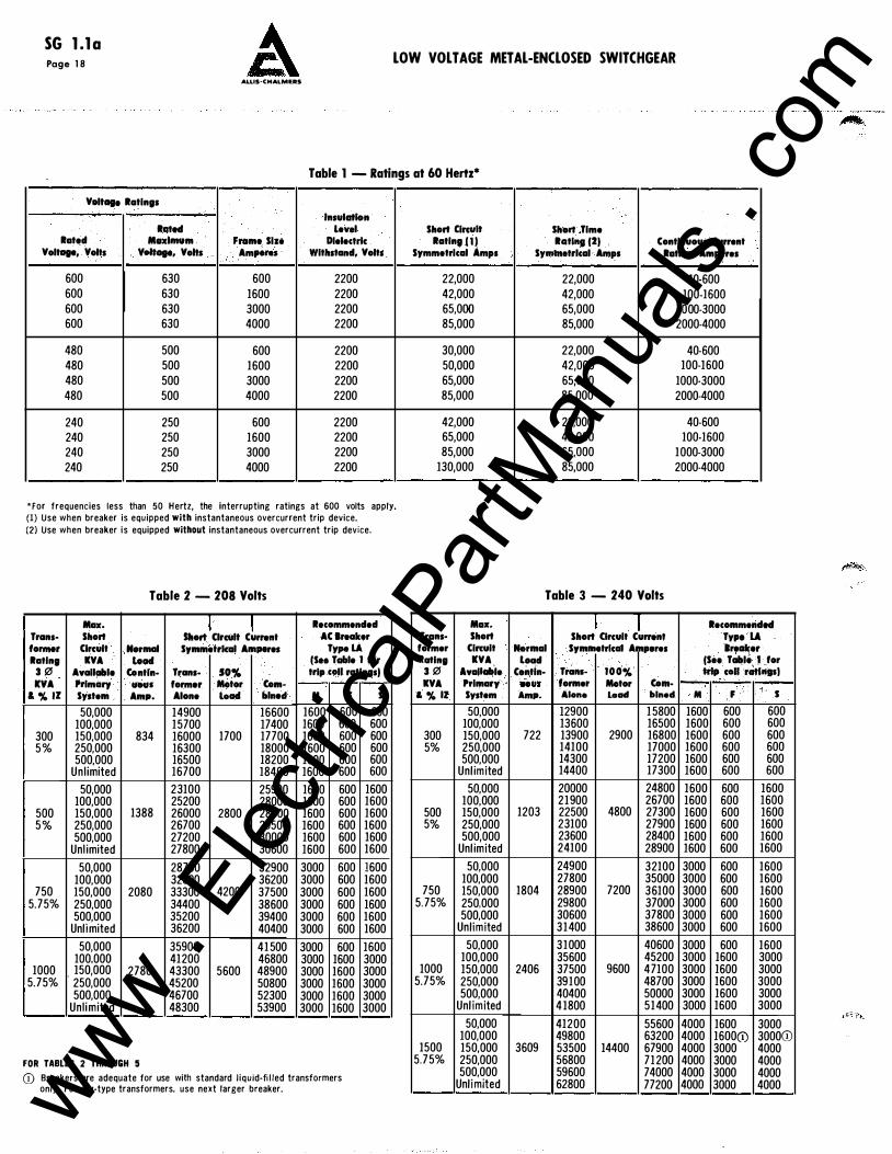
Table 1 - Ratings at 60 Hertz*
Voltage Ratings
Insulation Rated level
Rated Moxlmvm Frame Size Dielectric Voltage, Volts Voltage, Vohs Am,_ Withstand, Volts
600 630 600 2200 600 630 1600 2200 600 630 3000 2200 600 630 4000 2200
480 500 600 2200 480 500 1600 2200 480 500 3000 2200 480 500 4000 2200
240 250 600 2200 240 250 1600 2200 240 250 3000 2200 240 250 4000 2200
*for frequencies less than 50 Hertz, the interrupting ratings at 600 volts apply. (1) Use when breaker is equipped with instantaneous overcurrent trip device. (2) Use when breaker is equipped without instantaneous overcurrent trip device.
Table 2 - 208 Volts
Max. I _I Recommended Trans- Short Short Clrcvlt Currant AC iraaker forme!' Circuit Normal Symmetrical Amperes Type LA Rating IVA load (Sto Table 1 fOr
3 0 Available Con tin- Trans- SO% trip coli ratings) KYA Primary UOUS former Motor Com-
& % IZ System Amp. Alone load blned M F s 50,000 14900 16600 1600 600 600
100,000 15700 17400 1600 600 600 300 150,000 834 16000 1700 17700 1600 600 600 5 % 250,000 16300 18000 1600 600 600
500,000 16500 18200 1600 600 600 Unl imited 16700 18400 1600 600 600
50,000 23100 25900 1600 600 1600 100,000 25200 28000 1600 600 1600
500 150,000 1388 26000 2800 28800 1600 600 1600 5 % 250,000 26700 29500 1600 600 1600
500,000 27200 30000 1600 600 1600 Unl imited 27800 30600 1600 600 1600
50,000 28700 32900 3000 600 1600 100,000 32000 36200 3000 600 1600
750 150,000 2080 33300 4200 37500 3000 600 1600 5.75% 250,000 34400 38600 3000 600 1600
500,000 35200 39400 3000 600 1600 Unlimited 36200 40400 3000 600 1600
50,000 35900 41500 3000 600 1600 100,000 41200 46800 3000 1600 3000
1000 . 150,000 2780 43300 5600 48900 3000 1600 3000 5.75% 250,000 45200 50800 3000 1600 3000
500,000 46700 52300 3000 1600 3000 Unlimited 48300 53900 3000 1600 3000
FOR TABLES 2 THROUGH 5 (i) Breakers are adequate tor use with standard l iquid-fi l led transformers
only. For dry-type transformers, use next larger breaker.
Short Clrcvlt Rating 11 1
Symmetrical Amps
22,000 42,000 65,000 85,000
30,000 50,000 65,000 85,000
42,000 65,000 85,000
130,000
Max. Trans· Short former Circuit Rating IVA
3 0 Available IVA Primary
& % ll System
50,000 100,000
300 150,000 5% 250,000
500,000 Unl imited
50,000 100,000
500 150,000 5% 250,000
500,000 Unl imited
50,000 100,000
750 150,000 5.75% 250,000
500,000 Unlimited
50,000 100,000
1000 150,000 5.75% 250,000
500,000 Unlimited
50,000 100,000
1500 150,000 5.75% 250,000
500,000 Unlimited
Short Time Rating (2) Continuous Currant
Symlllatrlcal Amps Rating, Amperes
22,000 40-600 42,000 100-1600 65,000 1000-3000 85,000 2000-4000
22,000 40-600 42,000 100-1600 65,000 1000-3000 85,000 2000-4000
22,000 40-600 42,000 100-1600 65,000 1000-3000 85,000 2000-4000
Table 3 - 240 Volts
I J Recommended Short Circuit Currant Type LA
Normal Symmetrical Amperes Breaker Load (Sao Table 1 for
Con tin- Trans- 100% trfp coli ratings) UOUI former Motor Com-Amp. Alone load blned M F s
12900 15800 1600 600 600 13600 16500 1600 600 600
722 13900 2900 16800 1600 600 600 14100 17000 1600 600 600 14300 17200 1600 600 600 14400 17300 1600 600 600
20000 24800 1600 600 1600 21900 26700 1600 600 1600
1203 22500 4800 27300 1600 600 1600 23100 27900 1600 600 1600 23600 28400 1600 600 1600 24100 28900 1600 600 1600
24900 32100 3000 600 1600 27800 35000 3000 600 1600
1804 28900 7200 36100 3000 600 1600 29800 37000 3000 600 1600 30600 37800 3000 600 1600 31400 38600 3000 600 1600
31000 40600 3000 600 1600 35600 45200 3000 1600 3000
2406 37500 9600 47100 3000 1600 3000 39100 48700 3000 1600 3000 40400 50000 3000 1600 3000 4 1800 51400 3000 1600 3000
41200 55600 4000 1600 3000 49800 63200 4000 1600(1) 3000(i)
3609 53500 14400 67900 4000 3000 4000 56800 71200 4000 3000 4000 59600 74000 4000 3000 4000 62800 77200 4000 3000 4000 www .
Elec
tricalP
artM
anua
ls . c
om
Trans-former Rating
3 .0 KYA
& % II
300 5%
500 5%
750 5.75%
1000 5.75%
1500 5.75%
2000 5.75%
2500 5.75%
Max. Short Circuit KYA
AvaUable Primary System
50,000 100,000 150,000 250,000 500,000
Unl imited 50,000
100,000 150,000 250,000 500,000
Unl imited 50,000
100,000 150,000 250,000 500,000
Unl imited 50,000
100,000 150,000 250,000 500,000
Unl imited 50,000
100,000 150,000 250,000 500,000
Unl imited 50,000
100,000 150,000 250,000 500,000
Unl imited 50,000
100,000 150,000 250,000 500,000
Unl imited
LOW VOLTAGE METAL-ENCLOSED SWITCHGEAR
Normal load
Contln· vous Amp.
361
601
902
1203
1804
2405
3008
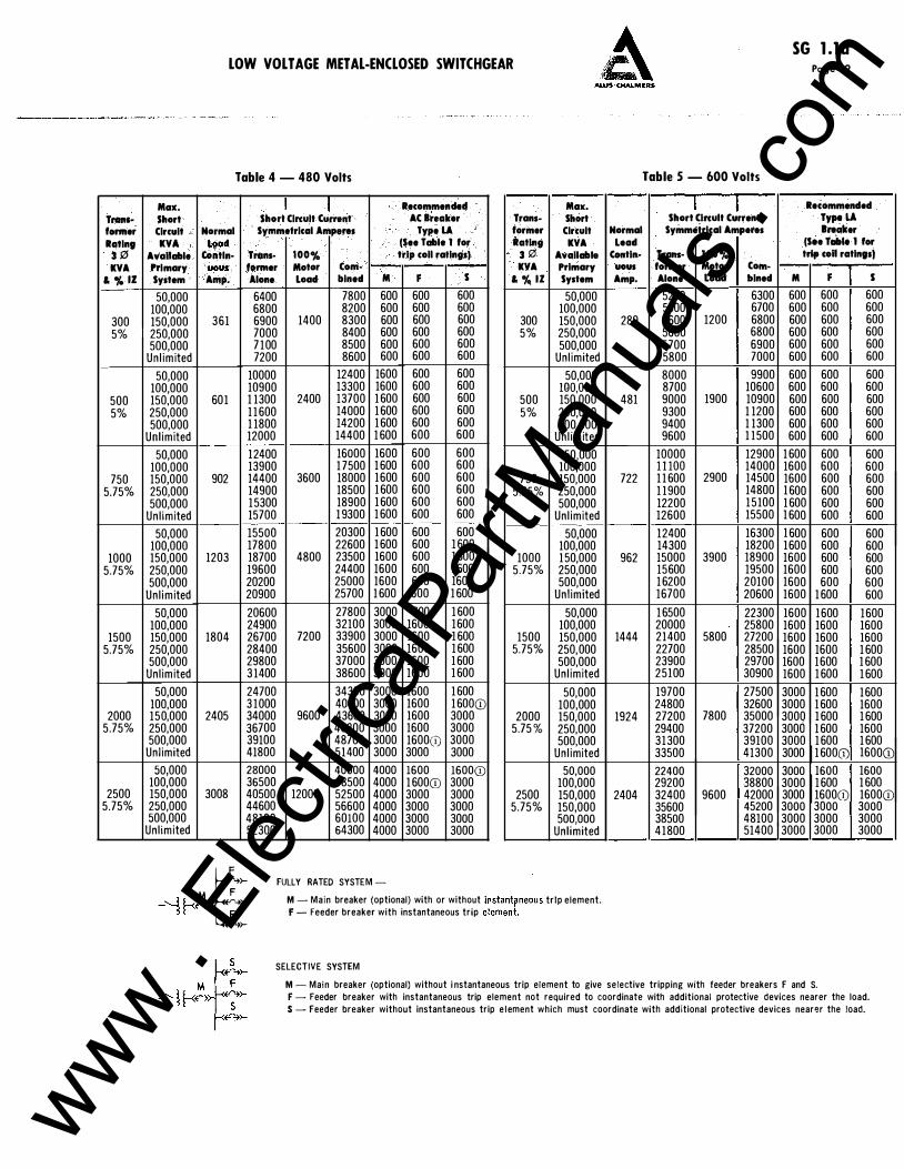
Table 4 - 480 Volts
I I Short Circuit Current
Symmetrical Amperes
Trans- 100% former Motor Com-Alone load bined
6400 7800 6800 8200 6900 1400 8300 7000 8400 7 100 8500 7200 8600
10000 12400 10900 13300 1 1300 2400 13700 1 1 600 14000 1 1800 14200 12000 14400
12400 16000 13900 1 7500 14400 3600 18000 14900 18500 15300 18900 15700 1 9300
15500 20300 17800 22600 18700 4800 23500 19600 24400 20200 25000 20900 25700
20600 27800 24900 32100 26700 7200 33900 28400 35600 29800 37000 3 1400 38600
24700 34300 3 1000 40600 34000 9600 43600 36700 46300 39100 48700 41800 51400
28000 40000 36500 48500 40500 12000 52500 44600 56600 48100 60100 52300 64300
M
600 600 600 600 600 600
1600 1600 1 600 1 600 1 600 1 600
1600 1 600 1600 1 600 1 600 1 600
1 600 1 600 1600 1600 1600 1 600
3000 3000 3000 3000 3000 3000
3000 3000 3000 3000 3000 3000
4000 4000 4000 4000 4000 4000
(-�-+>- FULLY RATED SYSTEM -
Recommended AC Breaker Trans-
Type LA former (See Table 1 for Rating trip coil ratings) 3 .0
KYA F s & % IZ
600 600 600 600 600 600 300 600 600 5% 600 600 600 600
600 600 600 600 600 600 500 600 600 600 600
5%
600 600
600 600 600 600 600 600 750 600 600 600 600
5.75%
600 600
600 600 600 1 600 600 1 600 1000 600 1 600 5.75% 600 1600 600 1 600
600 1 600 1600 1600 1600 1 600 1500 1600 1 600 5.75% 1600 1 600 1600 1 600
1600 1 600 1600 1 600CD 1600 3000 2000 1600 3000 5.75 % 1600(i) 3000 3000 3000
1600 1600CD 1 600CD 3000 3000 3000 2500 3000 3000 5.75% 3000 3000 3000 3000
Max. Short Circuit Normal KYA lead
Available Con tin· Primary uous System Amp.
50,000 100,000 150,000 289 250,000 500,000
Unl imited 50,000
HlO,OOO 150,000 481 250,000 500,000
Unl imited 50,000
100,000 150,000 722 250,000 500,000
Unl imited 50,000
100,000 150,000 962 250,000 500,000
Unl imited 50,000
100,000 150,000 1444 250,000 500,000
Unl imited 50,000
100,000 150,000 1924 250,000 500,000
Unl imited 50,000
100,000 150,000 2404 150,000 500,000
Unl imited
Table 5 - 600 Volts
I I Short Cinult Current
Symmetrical Amperes
Trans· 100% former Motor Com-Alone load bined
5200 6300 5500 6700 5600 1200 6800 5600 6800 5700 6900 5800 7000
8000 9900 8700 10600 9000 1900 10900 9300 1 1200 9400 1 1300 9600 1 1500
10000 12900 l l lOO 14000 1 1 600 2900 14500 1 1900 14800 12200 15100 12600 15500
12400 16300 14300 18200 15000 3900 18900 15600 19500 1 6200 20100 16700 20600
1 6500 22300 20000 25800 21400 5800 27200 22700 28500 23900 29700 25100 30900
19700 27500 24800 32600 27200 7800 35000 29400 37200 31300 39100 33500 41300
22400 32000 29200 38800 32400 9600 42000 35600 45200 38500 48100 41800 51400
SG l.la Page 1 9
Recommended Type LA Breaker
(See Table 1 for trip coD ratings)
M F s 600 600 600 600 600 600 600 600 600 600 600 600 600 600 600 600 600 600
600 600 600 600 600 600 600 600 600 600 600 600 600 600 600 600 600 600
1 600 600 600 1600 600 600 1600 600 600 1 600 600 600 1 600 600 600 1 600 600 600 1 600 600 600 1600 600 600 1600 600 600 1600 600 600 1600 600 600 1600 1 600 600
1600 1600 1600 1600 1600 1600 1600 1600 1600 1600 1600 1 600 1600 1600 1 600 1600 1 600 1 600
3000 1 600 1600 3000 1 600 1600 3000 1 600 1 600 3006 1 600 1600 3000 1 600 1 600 3000 1 600(1) 1600CD
3000 1600 1600 3000 1 600 1 600 3000 1600(i) 1600CD 3000 3000 3000 3000 3000 3000 3000 3000 3000
M F
t
F
-'-H-<� �-->(-�)-
M - Main breaker (optional) with or without instant� neous trip element. F - Feeder breaker with instantaneous trip element.
SELECTIVE SYSTEM
M - Main breaker (optional) without i nstantaneous trip element to give selective tripping with feeder breakers F and S. F - Feeder breaker with instantaneous trip element not required to coordinate with additional protective devices nearer the load. S - Feeder breaker without instantaneous trip e l ement which must coordinate with additional protective devices nearer the load.
www . El
ectric
alPar
tMan
uals
. com
SG l.la Page 20 LOW VOLT AGE METAL-ENCLOSED SWITCHGEAR
ALLIS·CHALMEAS
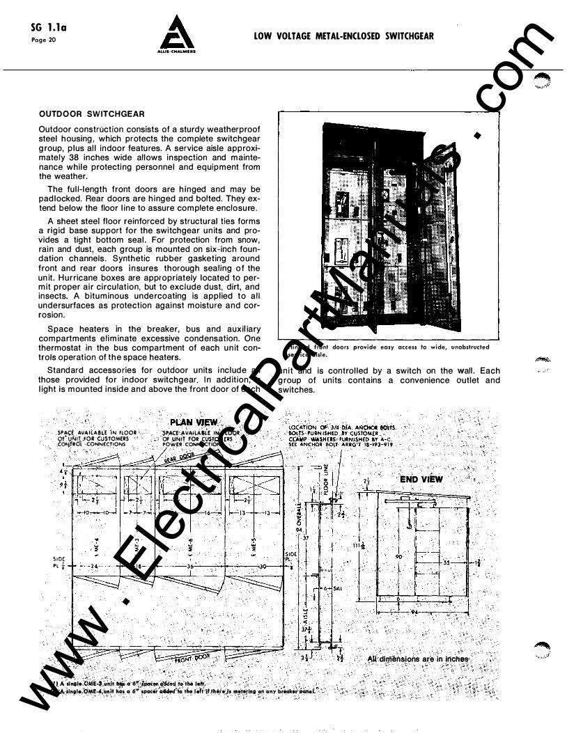
OUTDOOR SWITCHGEAR
Outdoor construction consists of a sturdy weatherproof steel housing, which protects the complete switchgear group, plus all indoor features. A service aisle approximately 38 inches wide allows inspection and maintenance while protecting personnel and equipment from the weather.
The full-length front doors are hinged and may be padlocked. Rear doors are hinged and bolted. They extend below the floor line to assure complete enclosure.
A sheet steel floor reinforced by structural ties forms a rigid base support for the switchgear un its and provides a tight bottom seal. For protection from snow, rain and dust, each group is mounted on six-inch foundation channels. Synthetic rubber gasketing around front and rear doors i nsures thorough sealing of the un it. H urricane boxes are appropriately located to permit proper air circu lation, but to exclude dust, dirt, and insects. A bituminous undercoating is applied to al l undersurfaces as protection against moisture and corrosion.
Space heaters in the breaker, bus and auxil iary compartments eliminate excessive condensation. One thermostat in the bus compartment of each un it controls operation of the space heaters.
Standard accessories for outdoor units i nclude all those provided for indoor switchgear. In addition, a light is mounted inside and above the front door of each
SPACE AVAILABLE IN FLOOR OF VNIT FOR CUSTOMERS CONTitOL CONNECTIONS
S ID( PL t
PLAN VIEW SPAC£ AVAilA8�E IN FLOOR OF VNtT FOR CUStOMERS POWER CONNECTIONS
(lJ A s1111l• OM!.4 unJt has a 6" si)O(er Odded to tiHI Ieft.
Hinged front doors provide easy access to wide, unobstructed service aisle.
unit and is controlled by a switch on the wall. Each group of units contains a convenience outlet and switches.
2 I L END VIEW
All dlmen�ions are in inches .
(2) A ''"'·'· oM!-l vnlt has Q 6" SPQC&r ad<lod lo the lett If th&re is lllelotino on GIIY breaker -··· www . El
ectric
alPar
tMan
uals
. com
LOW VOLT AGE METAL-ENCLOSED SWITCHGEAR A SG l.la Page 2 1
AI.LIS·CHAL.MERS
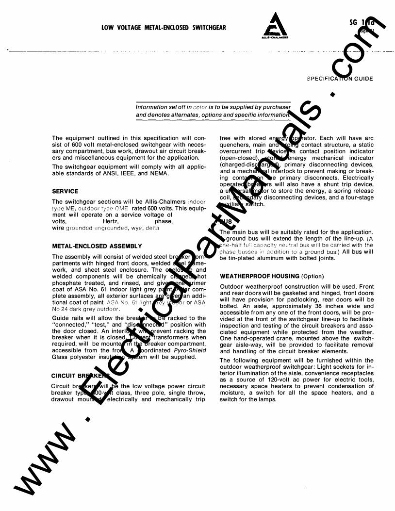
S P E C I FI CATI O N G U I D E
Information set off in ector is to be supplied by purchaser and denotes alternates, options and specific information.
The equipment outlined in this specification will con· sist of 600 volt metal-enclosed switchgear with necessary compartment, bus work, drawout air circuit breakers and miscellaneous equipment for the application.
The switchgear equipment will comply with all applicable standards of ANSI, IEEE, and NEMA.
SERVICE
The switchgear sections will be Allis-Chalmers i n d o o r type M E , o u t d o o r !yoe mv1 E rated 600 volts. This equipment will operate on a service voltage of volts, Hertz, phase, wire g ro u n d ed u n g r o u n d e d , wye , d e l t a
METAL-ENCLOSED ASSEMBLY
The assembly will consist of welded steel breaker compartments with hinged front doors, welded steel framework, and sheet steel enclosure. The enclosure and welded components will be chemically cleaned, hot phosphate treated, and rinsed, and given one primer coat of ASA No. 61 indoor l ight grey paint. After complete assembly, all exterior surfaces are given an additional coat of paint ASA N o . 61 i i g ht g rey i n d o o r or ASA N o 24 dark g rey o u td o o r .
Guide rails will allow the breaker to be racked to the "connected," "test," and "disconnected" position with the door closed. An interlock will prevent racking the breaker when it is closed. Current transformers when required, will be mounted in the breaker compartment, accessible from the front. A coordinated Pyro-Shieid Glass polyester insulation system will be supplied.
CIRCUIT BREAKERS
Circuit breakers will be the low voltage power circuit breaker type, 600-volt class, three pole, single throw, drawout mounted, electrically and mechanically trip
free with stored energy operator. Each will have arc quenchers, main and arcing contact structure, a static overcurrent trip device, a contact position indicator (open-closed), stored energy mechanical indicator (charged-discharged), primary disconnecting devices, and a mechanical interlock to prevent making or breaking contact on the primary disconnects. Electrically operated breakers will also have a shunt trip device, a universal motor to store the energy, a spring release coil, secondary disconnecting devices, and a four-stage auxiliary switch.
BUS
The main bus will be suitably rated for the application. A ground bus will extend the length of the line-up. {A o n e - h a l f f u : : c a o .,,c i ty n e u t r a l bus w i l l be carr ied with the phase b u sses i r1 a d d i t i o n :o a g round bus.) All bus will be tin-plated aluminum with bolted joints.
WEATHERPROOF HOUSING (Option)
Outdoor weatherproof construction will be used. Front and rear doors will be gasketed and hinged, front doors will have provision for padlocking, rear doors will be bolted. An aisle, approximately 38 inches wide and accessible from any one of the front doors, will be provided at the front of the switchgear line-up to facilitate inspection and testing of the circuit breakers and asso· ciated equipment while protected from the weather. One hand-operated crane, mounted above the switchgear aisle-way, will be provided to facilitate removal and handling of the circuit breaker elements.
The following equipment will be furnished within the outdoor weatherproof switchgear : Light sockets for interior illumination of the aisle, convenience receptacles as a source of 1 20-volt ac power for electric tools, necessary space heaters to prevent condensation of moisture, a switch for all the space heaters, and a switch for the lamps.
www . El
ectric
alPar
tMan
uals
. com
SG l.la Page 22 LOW VOLTAGE METAL-ENCLOSED SWITCHGEAR
ALLIS-CHALMERS
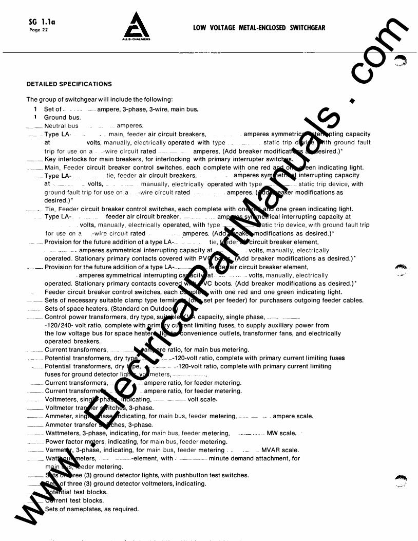
DETAILED SPECIFICATIONS
The group of switchgear will include the following:
1 Set of _ _ ampere, 3-phase, 3-wire, main bus. Ground bus.
_____ Neutral bus __ amperes.
___ _ Type LA- - __ m a i n , feed e r air circuit breakers, . amperes symmetrical interrupting capacity at volts, m a n u a l l y, electr ica l ly operate d with type _ stat i c trip d evice, with g ro u n d fault
t r i p for use on a - --w i re c i rc u i t rated ____ _ _ amperes. (Add breaker modifications as desired.) * ___ Key interlocks for main breakers, for interlocking with primary interrupter switches. _ --- Mai n , Feeder circuit breaker control switches, each complete with one red and one green indicating light.
_ ___ Type LA- .. t ie , feede r air circuit breakers, _ amperes symmetrical interrupting capacity at - volts, _ _ _ __ m a n u a l l y, electr i c a l l y operated with type __ ___ __ stat i c t r i p device, with g ro u n d fau l t t r i p for use on a _ _-wi re c i rc u it rated . amperes. (Add breaker modifications as desired.) *
___ _ _ Tie, Feede r circuit breaker control switches, each complete with one red and one green indicating light. _ __ Type LA- _ _ _ feeder air circuit breaker, ---- __ _ amperes symmetrical interrupting capacity at
. volts, m a n u a l l y, e l e ctr ical l y operated, with type __ ------ stati c t r i p device, with g ro u n d fault tr ip for use on a -w i re c i rc u it rated - -- - amperes. (Add breaker modifications as desired.) *
___ __ Provision for the future addition of a type LA--- - _ _ tie, feede r air circuit breaker element, - amperes symmetrical interrupting capacity at _ _ volts, m a n u a l l y, e lect r i c a l l y
operated. Stationary primary contacts covered with PVC boots. (Add breaker modifications as desired.) * Provision for the future addition of a type LA--- ___ _ - feeder air circuit breaker element, �.
- amperes symmetrical interrupting capacity at _ volts, m a n u al ly, e lectr ica l l y
operated. Stationary primary contacts covered with PVC boots. (Add breaker modifications as desired.) * Feeder circuit breaker control switches, each complete with one red and one green indicating light.
_ __ Sets of necessary suitable clamp type terminals (one set per feeder) for purchasers outgoing feeder cables. ___ __ Sets of space heaters. (Standard on Outdoor.) ____ Control power transformers, dry type, suitable KVA capacity, single phase, ---- --- -
·1 20/240- volt ratio, complete with primary current limiting fuses, to supply auxiliary power from the low voltage bus for space heaters, lights, convenience outlets, transformer fans, and electrically operated breakers.
_ _ ___ Current transformers, __ _ __ ampere ratio, for main bus metering. ___ Potential transformers, dry type _ -1 20-volt ratio, complete with primary current limiting fuses
_____ Potential transformers, dry type, _ _ - -- 1 20-volt ratio, complete with primary current limiting fuses for ground detector l ights, voltmeters, _ __ -- -- - -.
___ Current transformers, -- ------- - ampere ratio, for feeder metering. ____ Current transformers, _ __ ampere ratio, for feeder metering. __ Voltmeters, single--phase, indicating, ---- --- - - volt scale. ____ Voltmeter transfer switches, 3-phase. ___ Ammeter, s ingle-phase, indicating, for main bus, feeder metering, - - - ampere scale. ___ Ammeter transfer switches, 3-phase. ____ Wattmeters, 3-phase, indicating, for m a i n bus, feede r metering, - - -- MW scale. _____ Power factor meters, indicating, for m a i n bus, feed e r metering. ____ Varmeter, 3-phase, indicating, for main bus, feede r metering -- MVAR scale. ____ Watthour meters, - --- ---element, with - ---- - - - -- minute demand attachment, for
m a i n bus, feeder metering. _____ Sets of three (3) ground detector lights, with pushbutton test switches.
___ Sets of three (3) ground detector voltmeters, indicating.
__ Potential test blocks. __ Current test blocks. ___ Sets of nameplates, as required. www .
Elec
tricalP
artM
anua
ls . c
om
LOW VOLTAGE METAL-ENCLOSED SWITCHGEAR
ALLIS-CHALMERS
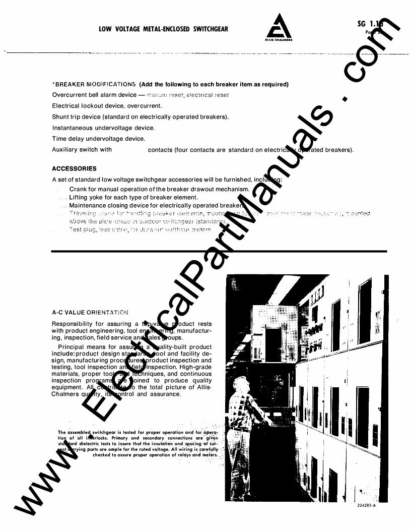
* BREAKER M O D I FI CATI ONS (Add the following to each breaker item as required)
Overcurrent bell alarm device- r� a n e� a i reset, e !ecir i cal reset
Electrical lockout device, overcurrent.
Shunt trip device (standard on electrically operated breakers).
Instantaneous undervoltage device.
Time delay undervoltage device.
Auxiliary switch with contacts (four contacts are standard on electrically operated breakers).
ACCESSORIES
A set of standard low voltage switchgear accessories will be furnished, including:
Crank for manual operation of the breaker drawout mechanism . . Lifting yoke for each type of breaker element.
_ Maintenance closing device for electrically operated breakers.
r {slanda:d l . Test p 1 u g , �e.:3s
A-C VAL U E O R I ENTATION
Responsibi l i ty for assu ri ng a top-value product rests with product engineering, tool engineering, manufacturing, inspection, field service and sales groups.
Principal means for assuring a quality-built product include: product design standards, tool and facility design, manufacturing procedures, product inspection and testing, tool inspection and field inspection. High-grade materials, proper tools and techniques, and continuous inspection programs are joined to produce quality equipment. All contribute to the total picture of AllisChalmers quality, its control and assurance.
The assembled switchgear is tested for proper operation and for operation of all interlocks. Primary and secondary connections are given standard dielectric tests to insure thai the insulation and spacing of current carrying parts are ample for the rated voltage. All wiring is carefully
checked to assure proper operation of relays and meters.
SG l.la Page 23
224285-A www . El
ectric
alPar
tMan
uals
. com
SG l.la Page 24 LOW VOLT AGE METAL-ENCLOSED SWITCHGEAR
ALLIS·CHALMEAS
1------ 36 ------+�-- 30 ME-6 ME-5 ME-4
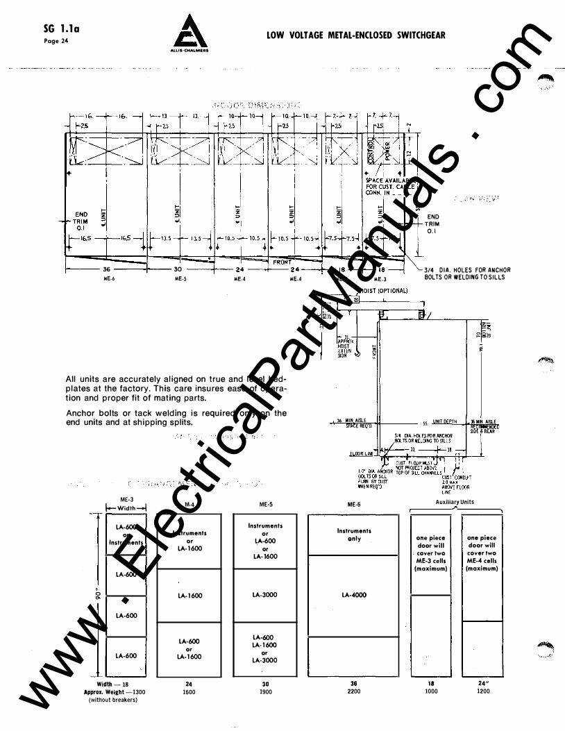
All units are accurately aligned on true and level bedplates at the factory. This care insures ease of operation and proper fit of mating parts.
Anchor bolts or tack welding is required only on the end units and at shipping splits.
--
• 0 0.
---''--
ME-3 f.-Width-! LA·600
or Instruments
LA-600
LA-600
LA-600
Widt_h - 18
Approx. Weight -1300 (without breakers)
M-4
Instruments or
LA-1 600
LA-1 600
LA-600 or
LA-1 600
24 1600
ME·S
Instruments or
LA-600 or
LA-1600
LA-3000
LA-600 LA-1 600
or LA-3000
30 1900
ME-4 ME-3
36 MIN AISLE E R Q D.
ME-6
Instruments only
LA-4000
36 2200
ME-3
END TRIM 0. 1
3/4 D IA . HOLES FOR ANCHOR BOLTS OR WELDING TO SILLS
55_ UNIT D PTH 36 MIN. AISLE
Auxiliary Units
one piece door will cover two ME-3 cells
(maximum)
18 1000
one piece door will cover two ME-4 cells (maximum)
24" 1200 www .
Elec
tricalP
artM
anua
ls . c
om
LOW VOLTAGE METAL-ENCLOSED SWITCHGEAR A SG l.la Page 25
ALUS-CHALMERS
·------------·-·---· ·-·--- -----�--------.--- -----
{-\.
ME-3
55 i /
I
� ·�-
r
' -
HINGED I I r--BREAKER
, • PANEL I RISERS ON L.H. I ic-
-1 ,_ '
h � E?�;;y 1--f- r-
SIDE OF
l U N I T
I 0 � -I
;--- I -' 1-- I -
l� -1 1\ II
� II I '\ li 4 --- - - -
I GROUND \ 6-1 2 BAR
l- 26 TO END CONNECTORS .\ OF BREAKER I LOCATION OF TERMINAL BLOCKS ON
STUDS ·
L.H. SIDE OF UNIT WHEN REQUIRED
INCOM I NG POWER CABLES CONNECT TO BREAKER STUDS ON 4 - I NCH CENTERS
� � � � � � -·-n � � � �
-��-+- -Lt. I GROUND BAR
CONNECTORS
0 "'
L26 TO E N D OF
BRKR STU D
LOCATION OF TERMINAL BLOCKS ON L.H. SIDE OF U N IT WHEN REQU IRED
ME·4
I N CO M I N G POWER CABLES CONNECT TO BREA�ER STUDS ON 6 - I NCH C E N T E R S
1nterruptfllf Frame Sfze \ > , c Cclpaclty at (MaximuM
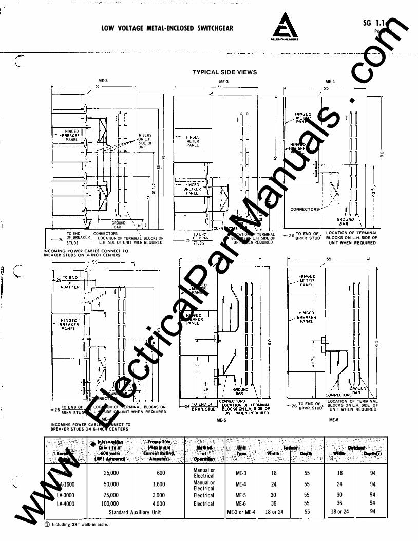
TYPICAL SIDE VIEWS
ME-3
�--------- 55 ------� �-----�-----� -----
!-- H I NGED
METER
PANEL
! I
� 26
I � �
� � 0 �
LOCATION OF TERMINAL BLOCKS ON L.H. SIDE OF
U N I T WHEN REQUIRED
.----------- 55 ----------�
H I N G E D M E T ER PAN E L
Method
ME-5
Unft
ME-4
�--------
55
----------1
CONNECTORS
L26 TO END OF B R K R STUD
0 � � � � � � � �
LOCATION OF TERMINAL
BLOCKS ON L.H. SIDE OF
UNIT WHEN REQU I R E D
""]•--------- 55 ---------...j
0 "'
L I LOCATION OF TERMINAL 26 TO END OF , BLOCK S ON L.H. SIDE O F BRKR. STUD UNIT WHEN REQUIRED
ME-6
..... , . Ouftle.t
0 "'
........ · 60'0 volts CIJI'I'IInt totlq, ef Type Width .,.,... Width ....... ® Type faMS Anlperes) AMperes) Opendlon
LA-600 25,000 600 Manual or ME-3 18 55 18 94 Electrical
LA-1600 50,000 1,600 Manual or ME-4 24 55 24 94 Electrical
LA-3000 75,000 3,000 Electrical ME-5 30 55 30 94
LA-4000 100,000 4.000 Electrical ME-6 36 55 36 94
Standard Auxi l iary Unit M E-3 or ME-4 18 or 24 55 18 or 24 94
(j) I ncluding 38" walk-in aisle. www . El
ectric
alPar
tMan
uals
. com
SG l.la Page 2 6 LOW """•'I':lli.,.,, .. �,,
600Vol1s Moxi•nj , 1S0,000 Aflll)l8res,tntt,...pttind:(Gp Al.LIS·CHALMERS
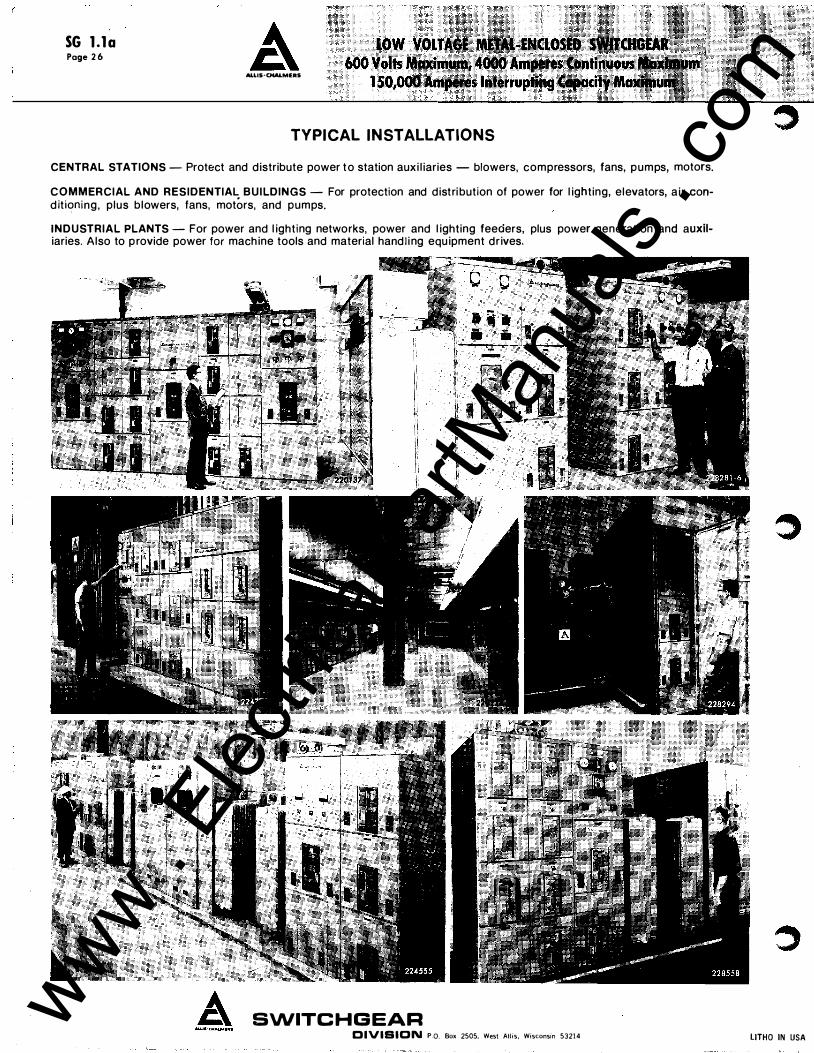
TYPICAL INSTALLATIONS CENTRAL STATIONS - Protect and d istribute power t o station aux i l iaries - blowers, compressors, fans, pumps, motors.
COMMERCIAL AND RESIDENTIAL BUILDINGS - For protection and d istri bution of power for l ighting, elevators, a ir cond itkming, plus blowers, fans, motors, and pumps.
INDUSTRIAL PLANTS - For power and l ighting networks, power and l ighting feeders, plus power generation and auxiliaries. Also to p rovide power for mach ine tools and material hand l i ng equ ipment d r ives.
SWITC HGEAR DIVISION P.O. Box 2505, West Allis, Wisconsin 53214 LITHO IN USA
www . El
ectric
alPar
tMan
uals
. com