Embed Size (px)
Citation preview

All P
roducts Guide Test &
Measurem
ent Instruments/M
eters & P
ortab
le Instruments
Vol.2
Yoko
gaw
a Meters &
Instruments C
orp
oratio
n
Catalog YMI130-EN
Test & Measurement Instruments/Meters & Portable Instruments
Represented by:
YOKOGAWA CORPORATION OF AMERICA2 Dart Road, Newnan, GA. 30265-1094 U.S.A.Phone: +1-770-253-7000 Facsimile: +1-770-254-0928
YOKOGAWA EUROPE B. V.Euroweg 2 3825 HD Amersfoort, THE NETHERLANDSPhone: +31-88-4641000 Facsimile: +31-88-4641111
YOKOGAWA ENGINEERING ASIA PTE. LTD.5 Bedok South Road, Singapore 469270 SINGAPOREPhone: +65-6241-9933 Facsimile: +65-6241-2606
YOKOGAWA AMERICA DO SUL LTDA.Praca Acapulco, 31-Santo Amaro, Sao Paulo/SP, BRAZIL CEP-04675-190Phone: +55-11-5681-2400Facsimile: +55-11-5681-4434
YOKOGAWA ELECTRIC KOREA CO., LTD.C&M Sales Seoul Office1301-1305, 13rd floor, Kolon digital tower, 106-1, Yangpyongdong-5Ga, Yeongdeungpo-Gu, Seoul, 150-105, KoreaPhone: +82-2-2628-3810 Facsimile: +82-2-2628-3899
YOKOGAWA AUSTRALIA PTY. LTD.Tower A/112-118 Talavera Road Macquarie Park, NSW 2113 AustraliaPhone: +61-2-8870-1100 Facsimile: +61-2-8870-1111
YOKOGAWA INDIA LTD. Plot No. 96. Electronic City Complex, Hosur Road, Bangalore 560100, INDIAPhone: +91-80-4158-6000 Facsimile: +91-80-2852-1441
YOKOGAWA SHANGHAI TRADING CO., LTD. 4F Tower D, Cartelo Crocodile Building, No.568 West Tianshan Road, Shanghai, CHINAPhone: +86-21-6239-6363 Facsimile: +86-21-6880-4987
YOKOGAWA MIDDLE EAST B. S. C.(C)P.O.BOX 10070, Manama, Building 577, Road 2516,Busaiteen 225, Muharraq, BAHRAINPhone: +973-17-358100 Facsimile: +973-17-336100
YOKOGAWA ELECTRIC CIS LTD.Grokholskiy per. 13, Build. 2, 4th Floor, 129090, MoscowRUSSIAN FEDERATIONPhone: +7-495-737-7868 Facsimile: +7-495-737-7869
World Wide Web site athttp://tmi.yokogawa.com
NOTICE Before using the product, read the instruction manual
carefully to ensure proper and safe operation.
Tachihi Bld. No.2, 6-1-3 Sakaecho, Tachikawa-shi, Tokyo, 190-8586 JapanPhone: +81-42-534-1413 Facsimile: +81-42-534-1438
YOKOGAWA METERS & INSTRUMENTS CORPORATIONInternational Sales Dept.
Subject to change without notice. [Ed: 02/b] Printed in Japan: May 2013(A)/7,500(KP)All Rights Reserved. Copyright © 2011, Yokogawa Meters & Instruments Corporation.
MIK-EL18

Oscilloscopes Digital Power Analyzer
Generators, Sources, Manometers etc. Optical Measuring Instruments
1G/10G Ethernet TesterAQ1300 Series
ScopeCorderDL850/DL850V
High-Speed Data Acquisition UnitSL1000
Mixed Signal OscilloscopesDL6000
Precision Power AnalyzerWT3000
Power AnalyzerWT500
Digital Power MetersWT300 Series
Source Measure UnitGS200
GS Series Accessory Software765670
Optical Spectrum AnalyzerAQ6370 Series
Optical Time Domain Refl ectmeterAQ7275
Optical Loss Test SetAQ1100
Multi Field Tester OTDRAQ1200 Series
The Yokogawa website offers not only product and technical information but also campaign information, user registration, document download, free software download, e-mail news subscription, catalog request, price inquiry, and lots of other content.
Internet Websitehttp://tmi.yokogawa.com
Precision Power AnalyzerWT1800
Mixed Signal OscilloscopesDLM4000
Multi Application Test SystemAQ2200 Series
AQ2170Series
new
Optical Wavelength MeterAQ6150 Series
new
AQ2180 Series
AQ4280 Series
new
Handy size Optical Power Meter / Light Source
new
BOOK_YMI130-EN 2 13.5.9, 10:30:58 AM
Data Logger
Handy Calibrator Digital Multimeter
Insulation TesterClamp-on Tester
Earth Tester ThermometerIlluminance MeterLeakage Current Tester
Precision Measuring Instruments Meters Products
Clamp-on Power Meter
MY10 Series 2406E Series 3213A SeriesMY40CL100Series
CL200Series
CL300Series
30031A30032A CL420
TY700 Series TY500 Series 732 Series 73101
279301 276910 201314 204102 205206
3226 TX10 SeriesTM203235 EY200
CA11E/CA12ECA71 CA450CA150
CW240 CW120 Series CW10
510 Series
XL120 Series
new
YMI130-EN_02-03.indd 3 13.5.9, 3:18:06 PM

[Digital Power Analyzers]Digital Power Analyzers Selection Guide.. 28Precision Power Analyzers (WT500 Series) .. 29Precision Power Analyzer (WT3000) ........ 30Precision Power Analyzer (WT3000) ........ 31High Performance Power Analyzer (WT1800) .. 32High Performance Power Analyzer (WT1800) .. 33Series Digital Power Meters (WT300) ...... 34Series Digital Power Meters (WT300) ...... 35Digital Power Meters (WT210/WT230) ..... 36Current Sensor Units................................ 37WT Series Accessories Software ............. 38Digital Power Analyzers Accessories List.. 39
28P~39P 2Digi
tal P
ower
Anal
yzer
s
[Generators, Sources, Manometers etc.]DC Voltage/ Current Source (GS200) ....... 40Multi Channel Source Measure Unit (GS820) ... 41Source Measure Unit (GS610).................. 42GS Series Accessory Software ................ 43AC Voltage Current Standard (2558A) ..... 44Digital Multimeters.................................... 45Pressure Standard & Manometers ........... 46Digital Manometer .................................... 47
40P~47P 3Gene
rato
rs,
Sour
ces,
Man
omet
ers
etc.
[Optical Measuring Instruments]Optical Spectrum Analyzer (AQ6370 Series) .... 48Optical Spectrum Analyzer (AQ6370C) .... 49Optical Spectrum Analyzer (AQ6375)....... 50Optical Spectrum Analyzer (AQ6373)....... 51Optical Wavelength Meter (AQ6150 series)... 52Multi Application Test System (AQ2200) ... 53Optical Time Domain Refl ectmeter (AQ7275).... 54MFT-OTDR (AQ1200)................................ 55Optical Power Meter (AQ2170)................. 56Optical Power Meter (AQ2180)................. 56Optical Light Source (AQ4280)................. 56MFT-OLTS (AQ1100)................................. 57MFT-1/10GbE (AQ1300 Series) ................ 58Remote OTDR (AQ7277) .......................... 59
48P~59P 4Optic
al M
easu
ring
Inst
rum
ents
[Oscilloscopes]ScopeCorder Series Selection Guide......... 8ScopeCorder Series Selection Guide......... 9ScopeCorder (DL850/DL850V)................. 10ScopeCorder (DL850/DL850V)................. 11ScopeCorder LITE (SL1400)..................... 12ScopeCorder Accessories........................ 13High-Speed Data Acquisition Unit (SL1000).. 14High-Speed Data Acquisition Unit (SL1000Acquisition Software) .................. 15PC-based Measuring Instruments (WE7000)... 16Application Software for WE7000
(7077 02/7077 14/7077 51/7077 61) ...... 17Digital and Mixed Signal Oscilloscopes Selection Guide ........................................ 18
Common Features of DL/DLM Series ...... 19Mixed Signal Oscilloscopes (DLM2000 Series)... 20Mixed Signal Oscilloscopes (DLM2000 Series)... 21Mixed Signal Oscilloscope Digital Oscilloscope (DLM6000 Series DL6000 Series) ...... 22Mixed Signal Oscilloscope Digital Oscilloscope (DLM6000 Series DL6000 Series) ...... 23Mixed Signal Oscilloscopes (DLM4000)...... 24Mixed Signal Oscilloscopes (DLM4000)...... 25Oscilloscope Accessories ........................ 26Oscilloscope Application Soft ware .......... 27
8P~27P 1Osci
llosc
opes
BOOK_YMI130-EN 4 13.5.9, 10:35:38 AM

123456789101112
1413
Osci
llosc
opes
Digi
tal P
ower
Anal
yzer
s
Gene
rato
rs,
Sour
ces,
Man
omet
ers
etc.
Optic
al M
easu
ring
Inst
rum
ents
Data
Log
ger
Clam
p-on
Pow
er M
eter
Hand
y Ca
libra
tor
Digi
tal M
ultim
eter
Clam
p-on
Tes
ter
Insu
latio
n Te
ster
Eart
h Te
ster
,Ot
her P
rodu
cts
Ther
mom
eter
Prec
isio
nM
easu
ring
Inst
rum
ents
Met
ers
Prod
ucts
[Clamp-on Power Meter]CW240, CW120/ CW121, CW10, 960Series
65P~69P 6Clam
p-on
Pow
er M
eter
[Handy Calibrator]CA150, CA51/CA71, CA11E/CA12E, CA450
70P~73P 7Hand
y Ca
libra
tor
[Digital Multimeter]TY700Series, TY500Series, 732Series, 73101
74P~77P 8Digi
tal M
ultim
eter
[Data Logger]Datum-Y (XL121/XL122/XL124)
62P~64P 5Data
Log
ger
[Precision Measuring Instruments]2723, 2768, 2755, 2752, 2769, 2792A, 2786, 2793, 2791, 2707, 2708
86P 13Precision Mea
surin
gIn
stru
men
ts
[Meters Products]2011~ 2042, 2051~ 2053, 2241~ 2243, 2261, 2215~ 2217, 2222~ 2223
87P 14Met
ers
Prod
ucts
[Thermometer]TM20, TX10Series
85P 12Ther
mom
eter
[Insulation Tester]MY40, MY10Series, 2406ESeries, 3213ASeries
80P~83P 10Insu
latio
n Te
ster
[Earth Tester, Other Products]3235, EY200
84P 11Earth Tester, Othe
r Pro
duct
s
[Clamp-on Tester]30031A/32A, CL100Series, CL200Series, CL300Series, CL400Series
78P~79P 9Clam
p-on
Tes
ter
Products with this mark conform to the EMC standards (reg u la tions on electromagnetic interference) of European Community.
BOOK_YMI130-EN 5 13.5.9, 10:35:41 AM

Optical Disk Sputtering Equipment
Maintenance & Calibration of Field Equipment
DC Characteristic Measurement of Two-Terminal Semiconductor Device
Battery Charge/Discharge Test
Interface of Plants and Atmospheric Environment Captured by Live Imaging
Current & Power Measurement of Electric Equipment Using Clamp Probe
Linearity Test of A/D Converter
Power Evaluation for Inverter/Motor Test (1)
Wire Bonding Machine Adjustment
Wide-Area Monitoring Model Example
Machine and Electronic Component Durability Test
Visualization of Welding Process in Laser Welding Machine
Robot Continuous Motion Test
Reliability Evaluation Test of ECU
Measurement of Current Consumption & Amount of Current of Fire Alarm Device
Loss Measurement & Bending Loss Detection for WDM Line Functional Multineuronal Calcium Imaging Technique
10G XFP Optical Transceiver Measurement System
Mobile Phone Current Consumption Measurement
Evaluation of Camera Drive for Digital Camera PC12 Cell Neurite Analysis
Light-Emitting Spectrum Evaluation of DFB-LD
Fire Detection, Disaster Prevention, & Energy Saving
Steering Dynamic Tester
Rotary Encoder Evaluation
16 A to 75 A IEC61000-3-11 Flicker Standard Test
Power Measurement by Calorie Meter
Flash Light Emission & Timing Evaluation
Inverter Evaluation Test
CAN Bus Signal Evaluation (Trigger)
Green IT: Power Consumption Measurement in Data Center
Engine Control Signal Analysis
I2C Bus Signal Evaluation (Trigger)
Robot Continuous Motion Test
Crystal Solar Cell Electrode Formation Equipment
Power Quality Evaluation Test of Uninterrupted Power Supply (UPS)
Characteristic Evaluation of Servo Motor
Large Equipment Maintenance
Evaluation & Verification of Power Line Communications (PLC) System
Maintenance & Calibration of Field Equipment
Yokogawa Meters & Instruments Corporation
Yokogawa Meters & Instruments Seeks the Trust of Customers
Yokogawa Meters & Instruments
Meters
Portable Test Instruments Basic Measuring Instruments
Optical Instruments
BOOK_YMI130-EN 6 13.5.9, 3:20:32 PM

Test & M
easurement Instrum
ents
Te s t & M e a s u r e m e n t I n s t r u m e n t s
BOOK_YMI130-EN 7 13.5.9, 10:35:50 AM

Osci
llosc
opes
Digi
tal P
ower
Anal
yzer
sGe
nera
tors
,So
urce
s,M
anom
eter
s et
c.
Optic
al M
easu
ring
Inst
rum
ents
Data
Log
ger
Clam
p-on
Pow
er M
eter
Hand
y Ca
libra
tor
Digi
tal M
ultim
eter
Clam
p-on
Tes
ter
Insu
latio
n Te
ster
Eart
h Te
ster
,Ot
her P
rodu
cts
Ther
mom
eter
Prec
isio
nM
easu
ring
Inst
rum
ents
Met
ers
Prod
ucts
Oscilloscopes
Osci
llosc
opes
8
The ScopeCorder series can be used to capture single-shot or infrequently recurring signals. They can also execute computations on repetitive waveforms, and automatically extract waveform parameters. The ScopeCorder series offers an extensive selection with large-capacity memories, powerful triggering func tions, and internal print ers. It also can save and
load data to and from internal or external media. SL1400 can provide big paper output capability for many applications in the fi eld.
Model
Item
DL850/DL850V
…P10
SL1400
…P12
Features High-speed (up to 100 MS/s*2), High Resolution (up to 16-bit*2), Isolated (up to 1kV*2)Multichannel, 128-CH voltage/temperature, 128-bit logic measurementContinuous hard disk recording at 100 kS/s simultaneously on 16 channels (option)Monitors CAN and LIN buses to display trend waveforms (DL850V only)17 types of plug-in modules
Compact, 16 ch isolated inputs (8 module slots)Eleven kinds of plug-in input modulesWeb server functionsA4 (210 mm) Big PrinterProbe power connectors
Max. sampling rate 100 MS/s (*2) 10 MS/s (*2)
Bandwidth 20 MHz (*2) 3 MHz (*2)
Number of analog input channels 128 ch max (when using eight 720220 modules) Plug-in module: 16 ch (isolation)
Logic input 128 bits max (when using eight 720230 modules) St’d: 16 (8 bits × 2)
Max. vertical sensitivity (1:1) 100 µV/div (*2) 1 mV range
Vertial axis resolution 16 bit (*2) Max. 16 bits (*2)
Max. sweep sensitivity 100 ns/div (*2) 100 µs Setting
Max. record length St’d 250 Mpts (MW) max/10 Mpts (MW) (16 ch) 50 MW max/2.5 MW (16 ch)
Optional 2 Gpts (GW) max / 100 Mpts (MW) (16 ch) —
Internal media drive selectable SD memory card slot PC card
Internal HDD Optional Internal 160 GB (FAT32) or external HDD 40 GB (FAT32)
Interface St’d USB2.0/ Ethernet (1000BASE-T) USB/GP-IB/RS232/SCSI
Optional GPIB Ethernet
Internal printer 112 mm width (optional) 210 mm width (st’d)
Others Optional • 17 types of plug-in modules• IRIG interface• User-defi ned math function
• Real time math function• Probe power (4-output)• DC 12V Power drive (DL850V only)
Probe Power Connectors
Display (TFT LCD) 10.4-inch color XGA 10.4-inch color, SVGA
External dimensions W × H × D (mm) 355 × 259 × 180 355 × 250 × 225
Weight (kg) Approx. 6.5 (*3) Approx. 8.0 (*3)
*1: See each product catalog for more detaled specifi cations *2: Depends on input module *3: Plug-in modules are not included
Waveform Measuring ScopeCorder Series Selection Guide (*1)
BOOK_YMI130-EN 8 13.5.9, 10:38:59 AM

Osci
llosc
opes
Digi
tal P
ower
Anal
yzer
s
Gene
rato
rs,
Sour
ces,
Man
omet
ers
etc.
Optic
al M
easu
ring
Inst
rum
ents
Data
Log
ger
Clam
p-on
Pow
er M
eter
Hand
y Ca
libra
tor
Digi
tal M
ultim
eter
Clam
p-on
Tes
ter
Insu
latio
n Te
ster
Eart
h Te
ster
,Ot
her P
rodu
cts
Ther
mom
eter
Prec
isio
nM
easu
ring
Inst
rum
ents
Met
ers
Prod
ucts
Oscilloscopes
Osci
llosc
opes
9
Model Description701250 High-speed 10 MS/s 12-bit Isolation module (2 CH)701251 High-speed 1 MS/s 16-bit Isolation module (2 CH)701255 High-speed 10 MS/s 12-bit non-Isolation module (2 CH)701260 High-voltage 100 kS/s 16-bit Isolation module (2 CH, with RMS)701261 Universal module (2 CH)701262 Universal module (with anti-aliasing fi lter, 2 CH)701265 Temperature/high-precision voltage module (2 CH)701270 Strain module (NDIS, 2 CH)701271 Strain module (DSUB, Shunt-CAL, 2 CH)701275 Accelaration module (with anti-aliasing fi lter, 2 CH)701280 Frequency module (2 CH)720210*9 High-speed 100 MS/s 12-Bit Isolation Module (2 CH)720220*9 Voltage Input Module(16 CH)720221*9 16 CH Temperature / Voltage Input Module720230*9 Logic Input Module (16 CH)720240*10 CAN Bus Monitor Module720241*10 CAN & LIN Bus Monitor Module
*9: Available for only DL850/DL850V. *10: Available for only DL850V.
Input Model No. Sample Rate Resolution Bandwidth Number of
Channels IsolationMaximum
Input Voltage(DC+ACpeak)
DC Accuracy Note
720210 100 MS/s 12-Bit 20 MHz 2 Isolated 1000 V*2
200 V*3 ±0.5% High speed · High voltage · Isolated Max. four (4) modules can be installed in a main unit.*6
701250*5 10 MS/s 12-Bit 3 MHz 2 Isolated 600 V*2
250 V*3 ±0.5% high noise immunity
AnalogVoltage
701251 1 MS/s 16-Bit 300 kHz 2 Isolated 600 V*2
140 V*3 ±0.25% High sensitivity range (1mV/div), low noise (±100 µVtyp.), and high noise immunity
701255*5 10 MS/s 12-Bit 3 MHz 2 Non-Isolated 600 V*4
250 V*3 ±0.5% non-isolation version of model 701250
701260 100 kS/s 16-Bit 40 kHz 2 Isolated 1000 V*2
850 V*3 ±0.25% with RMS, and high noise immunity
720220 200kS/s 16-Bit 5 kHz 16 Isolated(GND-terminal)non-isolated (CH-CH) 42V*3 ±0.3% 16CH voltage measurement (Scan-type)
Temperature
701261 100 kS/s (Voltage),500 S/s (Temperature)
16-Bit (Voltage),0.1: (Temperature)
40 kHz (Voltage),100 Hz (Temperature) 2 Isolated 42 V ±0.25%
(Voltage) thermocouple (K, E, J, T, L, U, N, R, S, B, W, iron-doped gold/chromel)
701262 100 kS/s (Voltage),500 S/s (Temperature)
16-Bit (Voltage),0.1: (Temperature)
40 kHz (Voltage),100 Hz (Temperature) 2 Isolated 42 V ±0.25%
(Voltage)thermocouple (K, E, J, T, L, U, N, R, S, B, W, iron-doped gold/chromel), with AAF
701265 500 S/s (Voltage),500 S/s (Temperature)
16-Bit (Voltage),0.1: (Temperature) 100 Hz 2 Isolated 42 V ±0.08 (Voltage) thermocouple (K, E, J, T, L, U, N, R, S, B, W, iron-doped gold/
chromel), high sensitivity range (0.1mV/div), and low noise (±4 µVtyp.)
720221*8 10 S/s 16-Bit 600 Hz 16 Isolated 42 V ±0.15% (Voltage)
16-CH voltage or temperature measurement (scan method)Thermocouple (K, E, J, T, L, U, N, R, S, B, W, Au-Fe-chromel)
Strain701270 100 kS/s 16-Bit 20 kHz 2 Isolated 10 V ±0.5% (Strain) Supports strain NDIS, 2, 5, 10 V built-in bridge power supply
701271 100 kS/s 16-Bit 20 kHz 2 Isolated 10 V ±0.5% (Strain) Supports strain DSUB, 2, 5, 10 V built-in bridge power supply, and shunt CAL
Analog Voltage,Acceleration 701275 100 kS/s 16-Bit 40 kHz 2 Isolated 42 V ±0.25% (Voltage)
±0.5% (Acceleration)built-in anti-aliasing fi lter, Supports built-in amp type acceleration sensors (4 mA/22 V)
Frequency 701280 25 kS/s 16-Bit resolution 50 ns 2 Isolated 420 V*2
42 V*3±0.1%
(Frequency)Measurement frequency of 0.01 Hz to 200 kHz, Measured parameters (frequency, rpm, period, duty, power supply frequency, distance, speed)
Logic 720230 10 MS/s — — 8-bit x2 ports non-isolated depend on logic
probe used. — (8-bit/port) x 2, compatible with four-type of logic probe (sold separately)
CAN 720240 100 kS/s — — (60signalsx2)port Isolated 10V —
CAN Data of max. 32-bit allowableIt is available for DL850V only. Max two (2) modules can be installed in a main unit.*6 *7
CAN,LIN 720241 100 kS/s — — (60signalsx2)port Isolated 10 V (CAN port)
18 V (LIN port) — CAN port x 1, LIN port x 1Available for DL850V only, up to 2 modules*6 *7
*1: Probes are not included with any modules. *2: In combination with 10:1 probe model 700929 *3: Direct input *4: In combination with 10:1 probe model 701940 *5: Some of the models 701250/701255 shipped on or before July, 2007 may require factory rework. *6: Any other modules can be installed in the remaining slots. *7: Up to two CAN Bus Monitor Modules (720240) or CAN & LIN Bus Monitor Modules (720241) in total can be used on a single main unit. *8: The 16-CH Scanner Box (701953) is required for measurement.
Plug-in Module Selection Guide*1
BOOK_YMI130-EN 9 13.5.9, 10:39:06 AM
Osci
llosc
opes
Digi
tal P
ower
Anal
yzer
sGe
nera
tors
,So
urce
s,M
anom
eter
s et
c.
Optic
al M
easu
ring
Inst
rum
ents
Data
Log
ger
Clam
p-on
Pow
er M
eter
Hand
y Ca
libra
tor
Digi
tal M
ultim
eter
Clam
p-on
Tes
ter
Insu
latio
n Te
ster
Eart
h Te
ster
,Ot
her P
rodu
cts
Ther
mom
eter
Prec
isio
nM
easu
ring
Inst
rum
ents
Met
ers
Prod
ucts
Oscilloscopes
Osci
llosc
opes
10
High Speed, Multichannel and IsolatedHigh Speed, Multichannel and IsolatedNoise-resistant, Ultra-fast Memory RecorderNoise-resistant, Ultra-fast Memory Recorder
DL850VDL850
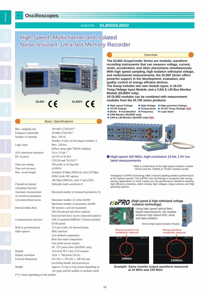
The DL850 ScopeCorder Series are modular, waveform recording instruments that can measure voltage, current, strain, acceleration, and other phenomena simultaneously. With high speed sampling, high isolation withstand voltage, and multichannel measurements, the DL850 Series offers powerful support in the development, evaluation, and quality control of energy effi cient devices.The lineup includes two new module types: A 16-CH Temp./Voltage Input Module, and a CAN & LIN Bus Monitor Module (DL850V only).All DL850 modules can be combined with measurement modules from the DL750 series products:
High-speed 100 MS/s, high-resolution 12-bit, 1 kV iso-lated measurements
Yokogawa's isoPRO technology offers industry leading isolation performance at the highest speeds. The isoPRO core technology is designed with energy savings applications in mind. It gives you the performance needed to develop high effi ciency inverters, which employ high voltages, large currents, and high operating speeds.
Max. sampling rate 100 MS/s (720210)(*1)
Frequency bandwidth 20 MHz (720210)(*1)
Number of channels Max. 128 ch,
Number of slots for the plug-in module: 8
Logic input Max. 128 bits
(When using eight 720230 modules)
A/D conversion resolution 16 or 12 bits (1*)
DC accuracy ±(0.5% of 10 div)
(701250 and 701255)(*1)
Time axis setting 100 ns/div to 30 days/div
Time axis accuracy ±0.005%
Max. record length Standard 10 Mpts (MW)/ch, total 250 Mpts
(MW) (with /M2 option)
100 Mpts (MW)/ch, total 2 Gpts (GW)
Channel-to-channel Defi nable math waveforms 8
calculation function
Automatic measurement Maximum number of measured parameters 32
of waveform parameters
Cycle statistical/historic process Maximum number of cycles 64,000
Maximum number of parameters 64,000
Internal media drive SD memory card slot (standard)
160 GB internal hard drive (option)
External hard drive can be connected (option)
Communication interface USB 2.0 (standard)/1000BASE-T Ethernet (standard)
GP-IB (option)
Built-in printer(option) 112-mm width, A6 thermal printer
Other options IRIG interface
User defi ned computation
Real time math computation
Four probe power outputs
DC 12V power drive (DL850V only)
Display 10.4-inch TFT color LCD monitor
Display resolution 1024 768 pixels (XGA)
External dimensions 355 (W) 259 (H) 180 (D) mm
(excluding handle and protrusions)
Weight Approx. 6.5 kg to 9 kg (varies depending on
the types and the number of modules used)
(*1): Varies depending on the module.
High-speed Voltage High Voltage High-precision Voltage 16-CH Voltage Temperature 16-CH Temp./Voltage Strain Acceleration Frequency Logic Input CAN Monitor (DL850V only) CAN & LIN Monitor (DL850V only)
NEW!
NEW!
(High-speed & high withstand voltage isolation technology)
Rising waveform not completely captured
Rising waveform completely captured
Using high speed optical fiber-based transmissions, the module achieves high speed ADC clock and data isolation.
720210 High-speed Isolation Module
Example: Same inverter output waveform measured at 10 MS/s and 100 MS/s
10MS/s 100MS/s
* With a combination of the high-speed isolation module 720210 and the 700929 or 701947 isolation probe
ScopeCorder DL850/DL850V
Overview
Basic Specifi cations
BOOK_YMI130-EN 10 13.5.9, 10:39:07 AM

Osci
llosc
opes
Digi
tal P
ower
Anal
yzer
s
Gene
rato
rs,
Sour
ces,
Man
omet
ers
etc.
Optic
al M
easu
ring
Inst
rum
ents
Data
Log
ger
Clam
p-on
Pow
er M
eter
Hand
y Ca
libra
tor
Digi
tal M
ultim
eter
Clam
p-on
Tes
ter
Insu
latio
n Te
ster
Eart
h Te
ster
,Ot
her P
rodu
cts
Ther
mom
eter
Prec
isio
nM
easu
ring
Inst
rum
ents
Met
ers
Prod
ucts
Oscilloscopes
Osci
llosc
opes
11
Up to 128 channels of voltage input, and 128 bits of logic inputThe 16-channel Voltage Input Module (scanner type) can measure at 10 kS/s sample rate even when using all 16 channels. With this module populating all 8 input moduleslots, the DL850 performs 128-channel voltage measurements. The Logic Input Module supports everything from TTL levels to contact inputs. With eight logic modules, the DL850 can monitor and capture 128 bits of logic.
* A response time for the logic input varies depending on the logic probe used.
Power supplies used in home computing electronics have many outputs; therefore, there are many measurement points. With a multichannel module, you are not limited to voltage measurements; a single unit can also measure everything from PC control signals to AC fan operation and slow to high-speed signals.
Large 2-GPoint memory (option) offers long duration measurement and two instantaneous zoom locationsComes standard with 250 MPoints of memory, expandable with 1 or 2 GPoint options. Large capacity memory does not simply provide longer durations of measurement. It makes it possible to measure at a higher sampling rate at the same measurement time.
Long Duration, Continuous Saving of Waveforms – Continuous hard disk recording (/HD0, /HD1 option) –
Measured data can be streamed directly to a built-in 160 GB hard disk (option) or through the external HDD interface (option). With long duration evaluation testing, measurements can be performed at 100 kS/s on 16 channels simultaneously for 10 hours*.
* The /HD0 and /HD1 options cannot be specifi ed together. The measurement time depends on the performance of the hard drive connected through the external HDD interface.
Data being continuously recorded on the DL850/DL850V's built-in HDD (/HD1 option) can be transferred to a PC without stopping measurement*. You can display and analyze the transferred waveform data using Xviewer, an accessory program for the PC.
* This function is an option of the optional software Xviewer.
Model Number and Suffi x Codes
Main screen:20 days of recording (2 days/div)
Zoom screen:1 hour (12 min/div)
&1 second (100 ms/div)
By a factor of 1,728,000
Instantly zooms 1 second (100 ms/div) even when the main screen is displaying 20 days of recording (2 days/div)
Long memory does not guarantee better efficiency if the memory handling and display engine is slow. Our faster than ever GIGAZoom 2 Engine instantaneously zooms into two locations.
Models of dedicated Plug-in Modules for DL850/DL850V
Model Description720210 High-speed 100 MS/s 12-Bit Isolation Module (2 ch)720220 Voltage Input Module(16 ch)720221 16-CH Temperature/Voltage Input Module
701953-L1 16-CH Scanner Box (provided with 1 m cable)701953-L3 16-CH Scanner Box (provided with 3 m cable)
720230 Logic Input Module (16 ch)720240 CAN Bus Monitor Module (32 ch, available DL850V only)720241 CAN & LIN Bus Monitor Module
Note 1: Up to two 720240 or 720241 modules in total can be installed in a single DL850V main unit.Note 2: Max. four(4) 720210 modules can be installed in a main unit.Note 3: The use of a 720221 module always requires the External Scanner Box (model 701953).Note 4: The fi rmware ver2.00 or later is required when using 720221 and/or 720241 module.
Divides and saves measured data across multiple files!
Key Point 1 Key Point 2
Ethernet or USB
Divided files are automatically uploaded and linked.
Xviewer
If an abnormality occurs during a long duration continuous test, you can analyze the saved measured data with a PC without having to stop measurement !
Critical measured data can be easily duplicated on the main unit and a PC.
720230 Logic Input Module (left photo)720220 16-channel Voltage Input Module (right photo)
Zoom to 2 locationsinstantaneously
Zoom to 2 locationsinstantaneously
Processes noise rejection and executes power compu-tations in real time– Real time Math (/G3 option) –
The DL850 is armed with a dedicated DSP (digital signal processor) for computations that enables between-channel math during waveform capture. These between-channel computations are powerful because they can be set up separately from fi lter computations. In addition to FIR, IIR, Gauss, and moving average digital fi lters, you can use maximum 35 equations such as arithmetic with coeffi cients, integrals and differentials, and higher-order equations.simultaneously for 10 hours*.
12 V DC (10 – 18 V)
100 V AC (100 – 120 V)200 V AC (200 – 240 V)
Low power consumption of 60 – 120 VA (typ.)Low noise
Low power consumption of 60 – 120 VA (typ.)Low noise
Compact thin type(Depth: 20 mm / weight: 800 g)
Can be driven by external DC power such as the vehicle’s battery
Can also be driven by AC power.
Support for both AC and DC power (/DC option, DL850V only) Support for both AC and DC power (/DC option, DL850V only)
Models and Suffi x Codes
Model Suffi x Codes DescriptionDL850 DL850 main unit, 250MPts(W) memory*1
DL850V DL850V main unit, 250MPts(W) memory*1
Power Code
-D UL and CSA standard-F VDE standard-R AS standard-Q BS standard-H GB standard
Languages
-HE English menu and panel-HJ Japanese menu and panel-HC Chinese menu and panel-HK Korean menu and panel-HG German menu and panel-HF French menu and panel-HL Italian menu and panel-HS Spanish menu and panel
Options
/B5 Built-in printer (112mm)*5
/DC DC12 V power (10-18 V DC) (can be specifi ed for DL850V only)*5
/M1 Memory expansion to 1GPts(W)*2
/M2 Memory expansion to 2GPts(W)*2
/HD0 External HDD interface*3
/HD1 Internal HDD (160GB)*3
/C1 GP-IB interface*4
/C20 IRIG and GP-IB interface*4
/G2 User-defi ned math function/G3 Real time math function
/P4 Four probe power outputs
*1: The main unit is not supplied with a plug-in module. *2, *3, *4, and *5: When selecting these, specify one of them.
The DL850V ScopeCorder Vehicle Edition can display CAN- and/or LIN-protocolcommunication data as trend waveforms on the display by using the CAN Bus Monitor Module (720240) or CAN & LIN Bus Monitor Module (720241*1). It can also trigger on decoded waveforms.
1:The CAN & LIN Bus Monitor Module (model: 720241) is supported by the main unitfi rmware ver. 2.00 or later.
http://www.scopecorder.net/ScopeCorder DL850ScopeCorder
Special Site• Product demonstrations (Flash)• ScopeCorder module list• Product specifications and comparison with previous models
BOOK_YMI130-EN 11 13.5.9, 10:39:35 AM

Osci
llosc
opes
Digi
tal P
ower
Anal
yzer
sGe
nera
tors
,So
urce
s,M
anom
eter
s et
c.
Optic
al M
easu
ring
Inst
rum
ents
Data
Log
ger
Clam
p-on
Pow
er M
eter
Hand
y Ca
libra
tor
Digi
tal M
ultim
eter
Clam
p-on
Tes
ter
Insu
latio
n Te
ster
Eart
h Te
ster
,Ot
her P
rodu
cts
Ther
mom
eter
Prec
isio
nM
easu
ring
Inst
rum
ents
Met
ers
Prod
ucts
Oscilloscopes
Osci
llosc
opes
12
ScopeCorder LITE SL1400
Easily & Quickly Saves Data to Memory and PaperEasily & Quickly Saves Data to Memory and Paper
SL1400
A plug-in module type chart recorder with a large built-in A4 sized high-resolution thermal printer
Overview
Basic Specifi cations
Input
Type Isolated plug-in module
Slots 8 (16 channels)
Logic inputs 16 (8 bits × 2)
Sweep time 100 us to 30 days
Display 10.4-inch color TFT liquid crystal display
Built-in printer
Printing method Thermal line-dot printing
Paper width 210 mm (Effective print width 200 mm)
Communication interface
GP-IB, USB peripheral equipment jacks
(USB keyboards and USB printers), USB (compiles
with Rev. 1.1, for con nec tion to PC), Ethernet (complies
with 100 BASE-TX and 10 BASE-T; with /C10 option),
serial (RS232), and SCSI
Internal media drives
PC card or Drive less (choose one), and 40GB hard drive
(with /C8 option)
External dimensions
355(W) × 250(H) × 225(D) mm
Weight Approx. 8.0 kg (main unit with full options, including
C8, C10 and P4)
Approx. 10.3 kg (main unit and eight 701250 modules)
Features
Model Number and Suffi x Codes
• Easy-to-operate
• Standard high resolution A4 size thermal printer
• Effective print width is 200 mm (1600-dot resolution)
• Compact body and isolated 16 analog channels, 8 slots and 16-bits logic
in put
• Eleven kinds of plug-in modules offers high accuracy and low
noise measurement and also offer various mea sure ment,
Voltage/ Current/Tem per a ture/Strain/Vibration/Fre quen cy
• 50MW large memory and 30 days observation
• Cycle statistical calculation
• Many Ethernet functions (Web server/FTP server/E-mail)
• Various communication interface USB/Ethernet/GP-IB/RS-232/ SCSI
• PC card drive is available
• 40 GB internal hard drive
• USB storage function is available
1. Plug-in modules are not included. 2. Choose only one.
Model701240
Power cable2
Internal media drive2
Language2
Other specifications
Suffix Code
-D-F-R-Q-H
-J0-J3
-HE-HJ-HC-HG-HF-HL-HK-HS
/C8/C10
/P4
DescriptionSL1400 main unit (16 isolated Channels, 8 slots + 16-bit logic)1
210 mm width A4 thermal printer built-inUL/ CSA standardVDE standardAS standardBS standardGB standard (Complied with CCC)non DrivePC card driveEnglish, Panel in English Japanese, Panel in Japanese Chinese, Panel in English German, Panel in English French, Panel in English Italian, Panel in English Korean, Panel in English Spanish, Panel in English Internal 40 GB HDD (FAT32)Ethernet optionProbe power (4-output)
Module Selection
* Above plug-in modules can be used among all ScopeCorder series.
Plug-in Module Model Numbers
7012
50
7012
51
7012
55
7012
60
7012
61
7012
62
7012
65
7012
70
7012
71
7012
75
7012
80
Model Description
701250 High-speed 10 MS/s 12-bit Isolation module (2 CH)
701251 High-speed 1 MS/s 16-bit Isolation module (2 CH)
701255 High-speed 10 MS/s 12-bit non-Isolation module (2 CH)
701260 High-voltage 100 kS/s 16-bit Isolation module (2 CH, with RMS)
701261 Universal module (2 CH)
701262 Universal module (with anti-aliasing fi lter, 2 CH)
701265 Temperature/high-precision voltage module (2 CH)
701270 Strain module (NDIS, 2 CH)
701271 Strain module (DSUB, Shunt-CAL, 2 CH)
701275 Accelaration module (with anti-aliasing fi lter, 2 CH)
701280 Frequency module (2 CH)
* Probes not included with any modules.
BOOK_YMI130-EN 12 13.5.9, 10:39:41 AM

Osci
llosc
opes
Digi
tal P
ower
Anal
yzer
s
Gene
rato
rs,
Sour
ces,
Man
omet
ers
etc.
Optic
al M
easu
ring
Inst
rum
ents
Data
Log
ger
Clam
p-on
Pow
er M
eter
Hand
y Ca
libra
tor
Digi
tal M
ultim
eter
Clam
p-on
Tes
ter
Insu
latio
n Te
ster
Eart
h Te
ster
,Ot
her P
rodu
cts
Ther
mom
eter
Prec
isio
nM
easu
ring
Inst
rum
ents
Met
ers
Prod
ucts
Oscilloscopes
Osci
llosc
opes
13
Waveform Measuring ScopeCorder Accessories
16-CH Temp./Voltage Input Module720221
Scanner Box 701953(Provided with a connecting cable)Note: This unit is always required for measurement.
Accessories Combinations
Logic inputModule720230
High-speed Logic Probe700986
Isolated Logic Probe700987
Logic Probe (TTL level/Contact Input)1m: 7029113m: 702912
Strain Module (NDIS)701270
Strain Module (DSUB Shunt-CAL)701271
Frequency Module701280
Probe Power 4-output701934
/P4, Probe Power 4-output (option)
High-speed 100 MS/s12-Bit Isolation Module720210
High-speed 1MS/s 16-bit Isolation Module701251
High-voltage 100kS/s 16-bit Isolation Module701260
Alligator Adapters758929
Fork Terminal Adapters758921
High-speed 10MS/s 12-bit Isolation Module701250
Large Alligator Clips (Dolphin Type)701954
Safety Mini Clips (Hook Type)701959
Alligator Adapters 758922
Plug on clip701948
Bridge Head (NDIS)120 Ohm: 701955350 Ohm: 701956
Bridge Head (DSUB, Shunt-Cal)120 Ohm: 701957350 Ohm: 701958
High-speed 10MS/s 12-bit Non-isolation Module701255
Acceleration/Voltage Module (with AAF)701275
Warning:Connect the probe earth cable to ground (grounding potential) when using these differential probes with isolation modules.
Passive Probe for SL1400/DL750701940
BNC cable1m: 3669242m: 366925
BNC-alligator cable366926
±500V, 15MHzDifferential Probe700925
±1400V, 100MHzDifferential Probe700924
7000Vpk, 50MHzDifferential Probe701926
Isolated Leads758917
Isolation probe700929
1:1 Safety BNC Adapter Lead701901
Isolation probe701947
Current Probe 30Arms DC-50MHz701933
Current Probe 150Arms DC-10MHz701930
Safety BNC Cable 1m : 7019023m : 701903
Current Probe 500Arms DC-2MHz701931
Universal Module701261
Universal Module (with AAF)701262
Temperature/High-precision Voltage Module701265
Shunt Resister for 4-20mA Measurement250 Ohm ± 0.1% : 438920100 Ohm ± 0.1% : 438921 10 Ohm ± 0.1% : 438922
1:1 Banana-alligator Cable366961
Product Model No. Description*1
Differential Probe 700925 DC to 15 MHz, 1/10-1/100 selector switch, max. allowable differential voltage ±500 V (DC + ACpeak)
Differential Probe 700924 DC to 100 MHz, 1/100-1/1000 selector switch, max. allowable differential voltage ±1400 V (DC + ACpeak) or 1000 Vrms (1/1000 range)
Current Probe 701933 30 Arms, DC to 50 MHz, supports probe power
Current Probe 701930 150 Arms, DC to 10 MHz, supports probe power
Current Probe 701931 DC to 2MHz, , 500Arms
Current Probe 701932 DC to 100MHz, 30Arms
Probe Power Supply 701934 Supply (4 outputs),large current output, external probe power
10:1 Probe (for Isolated BNC Input) 700929 1000 Vrms-CAT II
1:1 Safety BNC Adapter Lead(in combination with followings) 701901 1000 Vrms-CAT II
Safety Mini-Clips (Hook type) 701959 1000 Vrms-CAT II, 1 set each of red and black
Large Alligator-Clips (Dolphin type) 701954 1000 Vrms-CAT II, 1 set each of red and black
Passive Probe (10:1)*2 701940 Non-isolated 600 Vpk
1:1 BNC-Alligator Cable 366926 Non-isolated 42 V or less, 1m
*1 Actual allowable voltage is the lower of the voltages specifi ed for the main unit, probe and cable.*2 42 V is safe when using the 701940 with an isolated type BNC input.
BOOK_YMI130-EN 13 13.5.9, 10:39:45 AM
Osci
llosc
opes
Digi
tal P
ower
Anal
yzer
sGe
nera
tors
,So
urce
s,M
anom
eter
s et
c.
Optic
al M
easu
ring
Inst
rum
ents
Data
Log
ger
Clam
p-on
Pow
er M
eter
Hand
y Ca
libra
tor
Digi
tal M
ultim
eter
Clam
p-on
Tes
ter
Insu
latio
n Te
ster
Eart
h Te
ster
,Ot
her P
rodu
cts
Ther
mom
eter
Prec
isio
nM
easu
ring
Inst
rum
ents
Met
ers
Prod
ucts
Oscilloscopes
Osci
llosc
opes
14
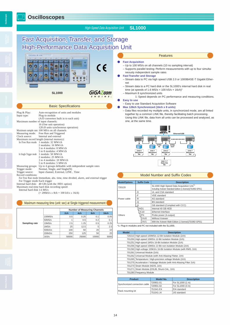
High-Speed Data Acquisition Unit SL1000
Fast Acquisition, Transfer, and StorageFast Acquisition, Transfer, and StorageHigh-Performance Data Acquisition UnitHigh-Performance Data Acquisition Unit
Fast Acquisition – Up to 100 MS/s on all channels (10 ns sampling interval) – Supports parallel testing: Perform measurements with up to four simulta-
neously independent sample rates Fast Transfer and Storage
– Stream data to PC via high speed USB 2.0 or 1000BASE-T Gigabit Ether-net
– Stream data to a PC hard disk or the SL1000's internal hard disk in real time (at speeds of 1.6 MS/s = 100 kS/s × 16ch)1
– Maximum 8 synchronized units1: Speed depends on PC performance and measuring conditions.
Easy to use – Easy to use Standard Acquisition Software
Max 128ch Synchronized (16ch x 8 units) – Data fi les recorded my multiple units, in synchronized mode, are all linked
together by a common LINK fi le, thereby facilitating batch processing. Using this LINK fi le, data from all units can be processed and analyzed, as one, at the same time.
Plug & Play: Auto-recognition of units and modules Input type: Plug-in module (A/D converters built in to each unit)Maximum number of input channels: 16 (One unit operation) 128 (8 units synchronous operation)Maximum sample rate: 100 MS/s on all channelsMeasuring mode: Free Run and TriggeredClock source: Internal and externalMaximum record length (internal memory): In Free Run mode 1 module: 32 MW/ch 2 modules: 16 MW/ch 3 to 4 modules: 8 MW/ch 5 to 8 modules: 4 MW/ch In Single Trigger mode 1 module: 50 MW/ch 2 modules: 25 MW/ch 3 to 4 modules: 10 MW/ch 5 to 8 modules: 5 MW/chMeasuring groups: Up to 4 groups defi nable with independent sample ratesTrigger mode: Normal, Single, and Single(N)Trigger source: Input channel, External, LINE , TimeRecord conditions: For Free Run mode Immediate, abs. time, time divided, alarm, and external trigger For Trigger mode Each triggerInternal hard disk: 40 GB (with the /HD1 option)Maximum real-time hard disk recording speed: Internal hard disk 1.6 MS/s (= 200kS/s × 8ch = 100 kS/s × 16ch)
Basic Specifi cations
Model Number and Suffi x Codes
Features
SL1000
Maximum measuring time (unit: sec) at Single triggered measurement
Unit 0Waveform
file
Unit 1Waveform
file
Unit 2Waveform
file
Unit 1-7Data link
file
Ethernet/USB
SYNCIN
SYNCOUT
Unit 7Waveform
file
Sampling rate
Number of Measuring Channels2ch 4ch 8ch 16ch
100MS/s 0.5 0.25 0.1 0.05
50MS/s 1 0.5 0.2 0.1
10MS/s 2.5 1.25 0.5 0.25
1MS/s 25 12.5 5 2.5
500kS/s 100 50 20 10
200kS/s 250 125 50 25
1kS/s 50000 25000 10000 5000
Model Description720210 High-speed 100MS/s 12-Bit Isolation Module (2ch)
701250 High-speed 10MS/s 12-Bit Isolation Module (2ch)
701251 High-speed 1MS/s 16-Bit Isolation Module (2ch)
701255 High-speed 10MS/s 12-Bit non-Isolation Module (2ch)
701260 High-voltage 100kS/s 16-Bit Isolation Module (with RMS, 2ch)
701261 Universal Module (2ch)
701262 Universal Module (with Anti-Aliasing Fileter, 2ch)
701265 Temparature / High-precision voltage Module (2ch)
701275 Acceleration / Volatage Module (with Anti-Aliasing Filter 2ch)
701270 Strain Module (NDIS, 2ch)
701271 Strain Module (DSUB, Shunt-CAL, 2ch)
701280 Frequency Module
Description
SL1000 High-Speed Data Acquisition Unit*1
Including Xviewer Standard Edition (1 license)(701992-SP01)
UL and CSA standard
VDE standard
AS standard
BS standard
GB standard (Complied with CCC)
Internal 40 GB HDD
Ethernet Interface
Probe power (4-output)
Without Xviewer
With the Xviewer Math Edition (1 license)(701992-GP01)
Suffix Code
-D
-F
-R
-Q
-H
/HD1
/C10
/P4
/XV0
/XV1
Model/Options
720120
Power cable
Others
*1: Plug-in modules and PC not included with the SL1000.
Product Model No. Description
Synchronized connection cable720901-01 For SL1000 (1 m)
720901-02 For SL1000 (3 m)
Rack mounting kit751541-E4 EIA standard
751541-J4 JIS standard
BOOK_YMI130-EN 14 13.5.9, 10:40:01 AM

Osci
llosc
opes
Digi
tal P
ower
Anal
yzer
s
Gene
rato
rs,
Sour
ces,
Man
omet
ers
etc.
Optic
al M
easu
ring
Inst
rum
ents
Data
Log
ger
Clam
p-on
Pow
er M
eter
Hand
y Ca
libra
tor
Digi
tal M
ultim
eter
Clam
p-on
Tes
ter
Insu
latio
n Te
ster
Eart
h Te
ster
,Ot
her P
rodu
cts
Ther
mom
eter
Prec
isio
nM
easu
ring
Inst
rum
ents
Met
ers
Prod
ucts
Oscilloscopes
Osci
llosc
opes
15
High-Speed Data Acquisition Unit SL1000 Acquisition Software
Setup Wizard Makes It EasyThe four screens of the Setup Wizard guide you easily through detailed settings for confi guring the system, measuring, saving, and displaying. You can save and recall your settings at any time.
Plug and Play Auto-recognition of units and modulesMeasurement modes Freerun and TriggeredACQ modes Normal, envelope, and box averageClock sources Internal and externalMeasurement groups Up to 4 groups defi nable with independent sample ratesTrigger modes Normal, single, and single(N)Trigger sources CH1-CH16, LINE, Time, and ExternalOther trigger functions Combination trigger, hold-off, pretriggers, and trigger delaySave conditions Manual operation, or based on time, or alarmsOther save functions Manual save (fi le division), specify no. of saves, save all data
in memory, and save simultaneously to PC’s hard disk and SL1000’s internal hard disk (with /HD1 option)
Save format Binary data fi le (original, *.wdf)Waveform data Binary data fi le(s) can be converted to ASCIIconversion (Xviewer) (*.csv) or Excel (*.xls) formatMaximum speed for saving in real time PC hard disk 1.6 MS/s (= 100 kS/s 16 channels)*1
Waveform monitor Trend display (displays measured waveforms of different sample rates simultaneously)*2, and instantaneous value displays (digital, bar graph, meter, and thermometer)
X-Y display X-axis channel settings, selection of main or zoomed waveform (in Triggered mode), and selection of the number of data points to draw (2 K, 10 K, 100 K)
Mark display (Free run mode) Setting of marks (up to 128 marks, each mark can display up to 16 characters), display color setting, mark editing, deletion of marks, mark list, collectively saving mark data with the same fi le name as the waveform data, and loading mark data into Xviewer.
Accumulation display Accumulates T-Y and X-Y waveformsSnapshot Waveform that is currently being displayed can be retained on
the screen as a snapshot waveform. Display color setting and snapshot waveform deletion
Display groups Up to 4 display groupsOther display functions History waveform, arbitrary axis divisions, and horizontal axis
scaling + specifi able units (external clock)Waveform analysis Cursor and parameter measurement*3
Offl ine waveform computation (with /XV1 option) Max. Number of displayed waveforms (CHs)
10 waveforms (Math1 to Math 10) Operations +, -, , /, trigonometry, differentiation/integration, FFT, and othersAlarms Channel (alarm display and alarm history analysis)*4, system
alarm, and alarm outputGO/NO-GO determination*3 Waveform parameter judgment and judgment outputSystem requirements OS Windows XP (SP2 or later) /Windows Vista (32-bit) /Windows
7 (32 bit /64 bit) CPU Pentium 4, 2 GHz or faster (3.2 GHz or faster when using the
auto-save function) Memory 1 GB or more Hard disk 500 MB or more of free space (40 GB or more when using the
auto-save function) Communication interfaces USB 2.0/Ethernet 1000BASE-T (with /C10 option) Display XGA or better, Color: 65536 colors or better Other CD-ROM drive and mouse
*1: Typical values. Actual values depend on PC performance and measurement conditions.*2: When the measurement mode is Free run, the trigger mode is Single(N), and the number
of measurements is Infi nite, there may be a limit to the number of channels that can be trend-displayed during measurement.
*3: Triggered measurement*4: Free run measurement
For details on 701992 Xviewer, see page 27.
Setup Wizard
Startmeasurement
Control Buttons––Just Like Your DVD RemoteMeasurement and saving can be started and stopped using the same familiar buttons found on a DVD remote control. Start using the instrument on the same day you receive it, with absolutely no programming required.
Main Specifi cations of Acquisition Software
Intuitive OperationEasy to UseEasy to Use
You can enter comments in the Mark area when monitoring over long periods of time (Free run mode).
Accumulating Waveforms
Displaying X-Y Waveforms
Setting Marks
You can view both T-Y waveform display and X-Y waveform display. Using its fast update feature, you can evaluate data quickly and easily.
Using the accumulation feature, you easily view unevenness of repetitive data.
BOOK_YMI130-EN 15 13.5.9, 10:40:03 AM

Osci
llosc
opes
Digi
tal P
ower
Anal
yzer
sGe
nera
tors
,So
urce
s,M
anom
eter
s et
c.
Optic
al M
easu
ring
Inst
rum
ents
Data
Log
ger
Clam
p-on
Pow
er M
eter
Hand
y Ca
libra
tor
Digi
tal M
ultim
eter
Clam
p-on
Tes
ter
Insu
latio
n Te
ster
Eart
h Te
ster
,Ot
her P
rodu
cts
Ther
mom
eter
Prec
isio
nM
easu
ring
Inst
rum
ents
Met
ers
Prod
ucts
Oscilloscopes
Osci
llosc
opes
16
PC-Based Measuring Instruments WE7000
Modular Type Measuring Instruments for Easy OperationModular Type Measuring Instruments for Easy Operation
Features
• Modular Design for easy operation
• Modules for a Variety of Signals and Extensive Features
• Easily Control All Modules Using the Control Software
• Control Software that brings out the full functionality of the WE7000
• Network-Friendly Measuring Instrument
USB2.0
Simply connect a USB cable and com mu ni ca tion is ready
Provides high-speed data com mu ni ca tion using USB 2.0 (up to 480
Mbps)
Ethernet (100Base-TX/10Base-T)
Enables remote monitoring and mea sure ment using the network such
as a corporate LAN
• Utility Software for More Convenience
• Transformation into Dedicated Mea sur ing Instrument by Customization
• Embedded Modules That Enable High Speed and In de pen dent
Processing (Option)
Overview
WE500 WE900
only on sale in the United States, the Unit ed Kingdom, Ger ma ny,
France, the Neth er lands, Spain, Italy, South Korea, Aus tra lia, and Japan.
Specifi cations
Number of slots: WE500: 5 measurement mod ules WE900: 9 measurement mod ules Interface for communicating with the PC: USB (Complies with USB Rev. 2.0), Ethernet (10Base-T or 100Base-TX)External dimensions: WE500: Approx. 213 (W) × 266 (H) × 360 (D) mm (projections ex clud ed) WE900: Approx. 350 (W) × 266 (H) × 360 (D) mm (projections ex clud ed)PC system requirements: OS: Windows XP /Windows Vista (32 bit) /Windows 7 (32 bit)
• Simple data acquisition with out any soft ware de vel op mentEach WE7000 system includes the standard con trol soft ware and each mod ule has its fi rmware resident within the mod ule.• Isolation and noise immunityIsolation and noise immunity are very important for mechanical elec tron ics. WE7000 has great isolation from the base sta tion to the input modules as well as channel to channel (de pend ing on the module) isolation.• Various precision modules with trace abil i tyWE7000 has various modules from 2 Hz to 20 MS/sec digitizing rates. There are also modules with signal out put capability, in clud ing a pre ci sion D/A and a function generator.• Remote control and monitoring using Ethernet Com mu ni ca tionWE7000 control, monitoring, and real time saving of data are all avail able using Ethernet communication.
WE7116 2-CH, 20 MS/sDigitizer Module
WE7275 2-CH, 1 MS/sIsolated Digitizer Module
WE7273 8-CH, 100 kS/sIsolated Digitizer Module
WE7271 4-CH, 100 kS/sIsolated Digitizer Module
WE7272 4-CH, 100 kS/sIsolated Digitizer Module
WE7251 10-CH, 100 kS/sDigitizer Module
WE7241 10-CHThermometer Module
WE7245 4-CH, 100 kS/sStrain Module
WE7235 4-CH, 100 kS/sAccelerometer Module
WE7521 4-CHTiming Measurement Module
WE7281 4-CH, 100 kS/sD/A module
WE7282 4-CH, 100 kS/sD/A Module
WE7262 32-BitDigital I/O Module
WE7081 CAN BusInterface Module
7071 16/HE
7072 75/HE
7072 73/HE
7072 71/HE
7072 72/HE
7072 51/HE
7072 41/HE
7072 45/HE
7072 35/HE
7075 21/HE
7072 81/HE
7072 82/HE
7072 62/HE
7070 81/HE
No
Yes
Yes
Yes
Yes
Yes
Yes
No
No
Yes
Yes
No
DC to 8 MHz
DC to 400 kHz
DC to 40 kHz
DC to 40 kHz
DC to 40 kHz
DC to 10 kHz
DC to 20 kHz
DC to 40 kHz
100 ns to 20 s
DC to 20 kHz
DC to 20 kHz
––
4 M
4 M
8 M
4 M
4 M
1 M
None
4 M
4 M
4 M
4 M
4 M
None
BNC
BNC
Clamp terminal
Clamp terminal
BNC
Input unit sold separately
Input unit sold separately
Dsub (9-pin)
BNC
BNC
Clamp terminal
BNC
Dsub (25-pin)
Dsub (9-pin)
1Approx. 0.7 kg
1Approx. 0.8 kg
1Approx. 0.9 kg
1Approx. 0.7 kg
1Approx. 0.7 kg
1Approx. 0.7 kg
1Approx. 0.8 kg
1Approx. 1 kg
1Approx. 0.8 kg
1Approx. 0.7 kg
1Approx. 0.9 kg
1Approx. 0.7 kg
1Approx. 0.6 kg
1Approx. 0.7 kg
Approx. 10 VA
Approx. 14 VA
Approx. 20 VA
Approx. 12 VA
Approx. 12 VA
Approx. 8 VA
Approx. 7 VA
Approx. 15 VA
Approx. 12 VA
Approx. 8 VA
Approx. 15 VA
Approx. 15 VA
Approx. 4 VA
Approx. 5 VA
18When 9 modules are linked
18When 9 modules are linked
72When 9 modules are linked
36When 9 modules are linked
36When 9 modules are linked
90When 9 modules are linked
90When 9 modules are linked
36When 9 modules are linked
36When 9 modules are linked
32When 8 modules are linked
––
––
32
64
Calibration signal output
Anti-aliasing filterOFF/20 Hz to 40 kHz (2-4-8 steps)
Multiplex type
Multiplex type
1, 2, or 4 gauges, DC bridgeGauge resistance 120 to 1 kΩ,auto balance
Anti-aliasing filterOFF/20 Hz to 40 kHz (2-4-8 steps)
Time stamp measurement
Sweep function, arbitrary waveform output
Sweep function, arbitrary waveform output
2-MHz counter featureConnect the 707823/707824 and input/output contact signals
CAN data I/O
12
14
16
16
16
16
14
15
16
––
16
16
––
Yes
Yes
Yes
Yes
Yes
Yes
Yes
Yes
Yes
Yes
Yes
Yes
No
Yes
Yes
Yes
Yes
Yes
Yes
Yes
Yes
Yes
Yes
––
––
––
Yes
Up to 1024
Up to 256
Up to 256
Up to 256
Up to 256
Up to 256
––
Up to 256
Up to 256
Up to 256
Up to 256
Up to 256
––
DC/AC
DC/AC
DC
DC
DC
DC
DC
DC/AC
––
––
––
±100 mV to 50 V(1-2-5 steps)
±100 mV to 200 V(1-2-5 steps), 350 V
±50 mV to 50 V(1-2-5 steps)
K, E, J, T, L, U, N, R, S, B, W, KPvsAU7Fe±50 mV to 50 V (1-2-5 steps)
1000 µ to 20000 µ strain,±100 mV to ±20 V (1-2-5 steps)
Gain: x1 (5 V) to x100 (50 mV)(1-2-5 steps)
2
2
8
4
4
10
10
4
4
4
4
4
32
ProductModel
Number Bandwidth Isolation RangeInput
CouplingResolution
bitMemory Partition
Power Consumption
Number of Used Slots
Weight
Link Feature
Maximum number of waveforms displayed
simultaneously
Scaling Feature Other Features
Maximum Memory(point)
I/O ConnectorNumber
of Channels
Scan interval0.5 s or longer
DC/AC/GND
NoL end
common
DC (voltage only)
/AC
±1 V to 20 V (1-2-5 steps), ±35 V
±1 V to 20 V (1-2-5 steps), ±35 V
±1 V to 20 V (1-2-5 steps)
Period, time interval, totalize count, up and down count,
and frequency ratio measurements
±1 V to 10 V (1-2-5 steps)
±1 V to 10 V (1-2-5 steps)
TTL level (input), CMOS level (output)
List of Measurement Module Features
BOOK_YMI130-EN 16 13.5.9, 10:40:09 AM
Osci
llosc
opes
Digi
tal P
ower
Anal
yzer
s
Gene
rato
rs,
Sour
ces,
Man
omet
ers
etc.
Optic
al M
easu
ring
Inst
rum
ents
Data
Log
ger
Clam
p-on
Pow
er M
eter
Hand
y Ca
libra
tor
Digi
tal M
ultim
eter
Clam
p-on
Tes
ter
Insu
latio
n Te
ster
Eart
h Te
ster
,Ot
her P
rodu
cts
Ther
mom
eter
Prec
isio
nM
easu
ring
Inst
rum
ents
Met
ers
Prod
ucts
Oscilloscopes
Osci
llosc
opes
17
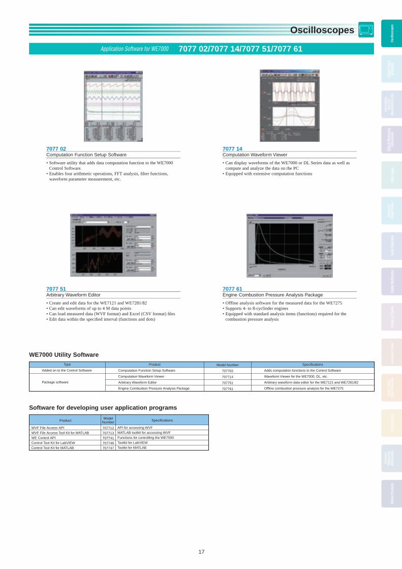
Application Software for WE7000 7077 02/7077 14/7077 51/7077 61
7077 02Computation Function Setup Soft ware
• Software utility that adds data com pu ta tion function to the WE7000 Control Soft ware.
• Enables four arithmetic operations, FFT anal y sis, fi lter functions, waveform pa ram e ter measurement, etc.
7077 14Computation Waveform Viewer
• Can display waveforms of the WE7000 or DL Series data as well as compute and an a lyze the data on the PC
• Equipped with extensive computation func tions
WE7000 Utility Software
Software for developing user application programs
Product
WVF File Access APIWVF File Access Tool Kit for MATLABWE Control APIControl Tool Kit for LabVIEWControl Tool Kit for MATLAB
Model Number
707712707713707741707746707747
Specifications
API for accessing WVFMATLAB toolkit for accessing WVFFunctions for controlling the WE7000Toolkit for LabVIEWToolkit for MATLAB
7077 51Arbitrary Waveform Editor
• Create and edit data for the WE7121 and WE7281/82• Can edit waveforms of up to 4 M data points• Can load measured data (WVF format) and Excel (CSV format) fi les• Edit data within the specifi ed interval (func tions and dots)
7077 61Engine Combustion Pressure Anal y sis Package
• Offl ine analysis software for the measured data for the WE7275• Supports 4- to 8-cyclinder engines• Equipped with standard analysis items (func tions) required for the
combustion pres sure analysis
Product
Computation Function Setup Software
Computation Waveform Viewer
Arbitrary Waveform Editor
Engine Combustion Pressure Analysis Package
Type
Added on to the Control Software
Package software
Model Number
707702
707714
707751
707761
Specifications
Adds computation functions to the Control Software
Waveform Viewer for the WE7000, DL, etc.
Arbitrary waveform data editor for the WE7121 and WE7281/82
Offline combustion pressure analysis for the WE7275
BOOK_YMI130-EN 17 13.5.9, 10:40:11 AM

Oscilloscopes
18
Osci
llosc
opes
Osci
llosc
opes
Osci
llosc
opes
Osci
llosc
opes
Digi
tal P
ower
Anal
yzer
sGe
nera
tors
,So
urce
s,M
anom
eter
s et
c.
Optic
al M
easu
ring
Inst
rum
ents
Data
Log
ger
Clam
p-on
Pow
er M
eter
Hand
y Ca
libra
tor
Digi
tal M
ultim
eter
Clam
p-on
Tes
ter
Insu
latio
n Te
ster
Eart
h Te
ster
,Ot
her P
rodu
cts
Ther
mom
eter
Prec
isio
nM
easu
ring
Inst
rum
ents
Met
ers
Prod
ucts
The DL/DLM series digital oscilloscopes have high-speed sampling and a wide range of bandwidths that can be utilized for design and development of electronic devices.
They can also execute computations on repetitive waveforms and automatically extract waveform parameters.
The DL/DLM Series offers an extensive selection of digital oscilloscopes with large-capacity memories, powerful triggering func tions, unique History Memory function and built-in printers. It also can save and load data to and from internal or external media.
ModelItem DLM4000 Series ...P24 DLM2000 Series ...P20 DL6000 Series ...P22 DLM6000 Series ...P22
Features Analog 8ch/Analog 7ch+Logic 8bitsLong memoryUART,I2C,SPI,CAN,LIN and FlexRaybus analysis functionsPower supply analysis functionsCompact & lightweightLarge display
Compact & lightweightAnalog 4ch/Analog 3ch+Logic 8bitsMax, 2.5GS/sUART,I2C,SPI,CAN LIN and FlexRay bus analysis functionsPower supply analysis functions
Easy to use and high performance, and 32-bit logic
Analog 4 channels1 GHz/1.5 GHz bandwidths, max 10 GS/s
Analog 4 channels + logic 321 GHz bandwidths, max 5 GS/s
High-speed acquisition: max 2.5 million waveforms/sec/channelSophisticated waveform computation, analysis and fast screen update
Max. sampling rate 2.5 GS/s 2.5 GS/s 10 GS/s(*2) 5 GS/s
Bandwidth 500 MHz(*2) 500 MHz(*2) 1.5 GHz(*2) 1.0 GHz(*2)
Number of analog input channels
8DLM2022,DLM2032,DLM2052:2DLM2024,DLM2034,DLM2054:4
4
Logic input 8 bits(*3) DLM2024, DLM2034, DLM2054: St’d 8 bits
None 32 bits (8 bits × 4)
Max. vertical sensitivity (1:1) 2 mV/div 2 mV/div 2 mV/div
Vertial axis resolution 8 bits 8 bits 8 bits
Max. sweep sensitivity 1 ns/div 1 ns/div 500 ps/div
Max. record length St’d 12.5 Mpoints 12.5 Mpoints 6.25 Mpoints
Optional 125 Mpoints 125 Mpoints —
Internal storageSt’d Approx. 1.8 GB Approx. 100 MB Approx. 390 MB
Optional Approx. 7.2 GB Approx. 1.8 GB —
Interface St’d USB/Ethernet USB USB/GP-IB(*4)
Optional GP-IB Ethernet/GP-IB Ethernet
Built-in printer Optional 112 mm width 112 mm width 112 mm width
Others Optional I2C bus analysisSPI bus analysisCAN & LIN bus analysisFlexRay bus analysisUART bus analysisProbe PowerPower Supply analysis functionsUser-defi ned math functions
I2C bus analysisSPI bus analysisCAN & LIN bus analysisFlexRay bus analysisUART bus analysisProbe PowerPower supply analysis functionsUser-defi ned math functions
• I2C bus analysis• SPI bus analysis• CAN & LIN bus analysis• UART bus analysis• User-defi ned math• Power supply analysis• Probe power
Display (TFT LCD) 12.1-inch color XGA 8.4-inch color, XGA 8.4-inch color, XGA
External dimensionsW × H × D (mm)
426 x 266 x 178 226 × 293 × 193 350 × 200 × 178 350 × 200 × 285
Weight (kg) Approx. 6.6 Approx. 4.2 Approx. 6.5 Approx. 7.7
*1: See each product catalog for more detaled specifi cations. *2: Depends on model *3: Additional logic 16 bits option is coming soon.*4: PCMCIA-GPIB card is required.
Waveform Measuring Digital and Mixed Signal Oscilloscopes Selection Guide
Number of analog input channels
Ban
dwid
th (
Hz)
2 4 6 8
1.5G
1.0G
500M
BOOK_YMI130-EN 18 13.5.9, 10:40:18 AM

Oscilloscopes
19
Osci
llosc
opes
Osci
llosc
opes
Osci
llosc
opes
Osci
llosc
opes
Digi
tal P
ower
Anal
yzer
s
Gene
rato
rs,
Sour
ces,
Man
omet
ers
etc.
Optic
al M
easu
ring
Inst
rum
ents
Data
Log
ger
Clam
p-on
Pow
er M
eter
Hand
y Ca
libra
tor
Digi
tal M
ultim
eter
Clam
p-on
Tes
ter
Insu
latio
n Te
ster
Eart
h Te
ster
,Ot
her P
rodu
cts
Ther
mom
eter
Prec
isio
nM
easu
ring
Inst
rum
ents
Met
ers
Prod
ucts
This feature meets the need to measure as many signals as possible simultaneously with one oscilloscope.
DLM2000/DLM4000 series
The DLM2000 (DLM4000) series usually functions as 4 (8) channel analog, and is able to switch CH 4 (8) of analog input to 8-bit logic quickly whenever the need arises.
DLM4000 series
Up to 8 channels of analog signals can be measured.
DLM6000 series
Up to 32-bit logic signals and 4 channels of analog signals can be measured simultaneously at high speed.
ScopeCorder Series is available for customers that require more channels for measurement (see page 2). The DL850 supports up to 128 channel measurement.
Common Features of DL/DLM Series
When the sample rate is increased with oscilloscopes with less memory, the observation time may run out. All of Yokogawa’s oscilloscope models are equipped with large capacity memory. For example, the DLM2000/DLM4000 offers long memory of up to 125 Mpoints for measurement.Even at a fast sample rate of 1.25 GS/s, waveforms for 0.1 seconds can be captured.The history memory function that divides the long memory can redisplay past waveforms that have disappeared from the screen.With the DLM2000/DLM4000 series, up to 20,000 previously captured waveforms can be saved in memory.
Since a large amount of data is also processed at high speed by dedicated hardware, the long memory can be used comfortably without sacrifi cing response time.
To facilitate the use of a PC, various interfaces such as USB, Ethernet, and GP-IB are available as standard or an option.In addition, various software is available to support remote control, fi le transfer, and data processing on a PC.USB memory and peripheral devices, such as keyboard and mouse, can be connected, and connecting to a PC using a USB cable enables it to be used as the external storage of the PC.
With a small built-in printer, measured waveforms can be printed to paper immediately (option with the exception of some models).
• A variety of triggers capture complex waveforms• Real time digital fi lter with optimum noise reduction• Zooms into two different points simultaneously• Automated measurement of waveform parameters and
statistical processing function• Frequency analysis by FFT computation• Go/No-Go function and action on trigger function to
determine abnormal waveforms and save fi les.• Analysis functions for specifi c applications, such as
serial bus analysis and power supply analysis (* Not available for some models)
LogicAnalog
Multichannel
Long Memory
Connection with a PC
Built-in Printer
A Variety of Triggers and Analysis Functions
USB memory USB keyboard
1000BASE-T/100BASE-TXcompliant adapters (hubs and routers)
Sends waveform, screenand settings dataRemote control
Sends waveform, screen, and settings dataRemote control
Mail transmission (GO/NO-GO action)
USB (standard on rear panel)
Internal storage (/C8 option)
Ethernet(/C10 and /C11 options)
Waveform history
BOOK_YMI130-EN 19 13.5.9, 10:40:26 AM
Oscilloscopes
20
Osci
llosc
opes
Osci
llosc
opes
Osci
llosc
opes
Osci
llosc
opes
Digi
tal P
ower
Anal
yzer
sGe
nera
tors
,So
urce
s,M
anom
eter
s et
c.
Optic
al M
easu
ring
Inst
rum
ents
Data
Log
ger
Clam
p-on
Pow
er M
eter
Hand
y Ca
libra
tor
Digi
tal M
ultim
eter
Clam
p-on
Tes
ter
Insu
latio
n Te
ster
Eart
h Te
ster
,Ot
her P
rodu
cts
Ther
mom
eter
Prec
isio
nM
easu
ring
Inst
rum
ents
Met
ers
Prod
ucts
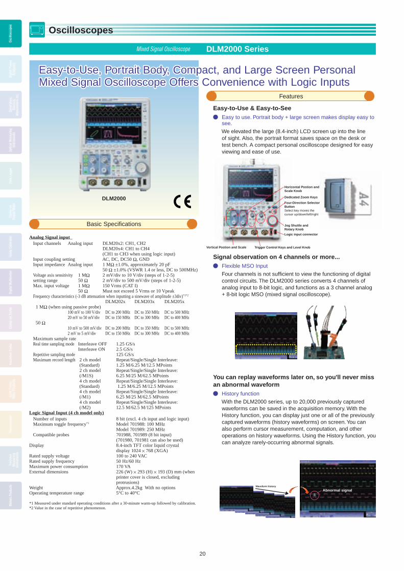
Easy-to-Use, Portrait Body, Compact, and Large Screen Personal Easy-to-Use, Portrait Body, Compact, and Large Screen Personal Mixed Signal Oscilloscope Offers Convenience with Logic InputsMixed Signal Oscilloscope Offers Convenience with Logic Inputs
Easy-to-Use & Easy-to-See Easy to use. Portrait body + large screen makes display easy to
see.
We elevated the large (8.4-inch) LCD screen up into the line of sight. Also, the portrait format saves space on the desk or test bench. A compact personal oscilloscope designed for easy viewing and ease of use.
Signal observation on 4 channels or more... Flexible MSO Input
Four channels is not suffi cient to view the functioning of digital control circuits. The DLM2000 series converts 4 channels of analog input to 8-bit logic, and functions as a 3 channel analog + 8-bit logic MSO (mixed signal oscilloscope).
You can replay waveforms later on, so you'll never miss an abnormal waveform
History function
With the DLM2000 series, up to 20,000 previously captured waveforms can be saved in the acquisition memory. With the History function, you can display just one or all of the previously captured waveforms (history waveforms) on screen. You can also perform cursor measurement, computation, and other operations on history waveforms. Using the History function, you can analyze rarely-occurring abnormal signals.
DLM2000
Analog Signal input Input channels Analog input DLM20x2: CH1, CH2 DLM20x4: CH1 to CH4 (CH1 to CH3 when using logic input) Input coupling setting AC, DC, DC50 Ω, GND Input impedance Analog input 1 MΩ ±1.0%, approximately 20 pF 50 Ω ±1.0% (VSWR 1.4 or less, DC to 500MHz) Voltage axis sensitivity 1 MΩ 2 mV/div to 10 V/div (steps of 1-2-5) setting range 50 Ω 2 mV/div to 500 mV/div (steps of 1-2-5) Max. input voltage 1 MΩ 150 Vrms (CAT I) 50 Ω Must not exceed 5 Vrms or 10 Vpeak Frequency characteristics (-3 dB attenuation when inputting a sinewave of amplitude ±3div)*1*2
DLM202x DLM203x DLM205x 1 MΩ (when using passive probe) 100 mV to 100 V/div DC to 200 MHz DC to 350 MHz DC to 500 MHz 20 mV to 50 mV/div DC to 150 MHz DC to 300 MHz DC to 400 MHz 50 Ω 10 mV to 500 mV/div DC to 200 MHz DC to 350 MHz DC to 500 MHz 2 mV to 5 mV/div DC to 150 MHz DC to 300 MHz DC to 400 MHz Maximum sample rate Real time sampling mode Interleave OFF 1.25 GS/s Interleave ON 2.5 GS/s Repetitive sampling mode 125 GS/s Maximum record length 2 ch model Repeat/Single/Single Interleave: (Standard) 1.25 M/6.25 M/12.5 MPoints 2 ch model Repeat/Single/Single Interleave: (/M1S) 6.25 M/25 M/62.5 MPoints 4 ch model Repeat/Single/Single Interleave: (Standard) 1.25 M/6.25 M/12.5 MPoints 4 ch model Repeat/Single/Single Interleave: (/M1) 6.25 M/25 M/62.5 MPoints 4 ch model Repeat/Single/Single Interleave: (/M2) 12.5 M/62.5 M/125 MPointsLogic Signal Input (4 ch model only) Number of inputs 8 bit (excl. 4 ch input and logic input) Maximum toggle frequency*1 Model 701988: 100 MHz Model 701989: 250 MHz Compatible probes 701988, 701989 (8 bit input) (701980, 701981 can also be used) Display 8.4-inch TFT color liquid crystal display 1024 × 768 (XGA)Rated supply voltage 100 to 240 VAC Rated supply frequency 50 Hz/60 Hz Maximum power consumption 170 VA External dimensions 226 (W) × 293 (H) × 193 (D) mm (when
printer cover is closed, excluding protrusions)
Weight Approx.4.2kg With no optionsOperating temperature range 5°C to 40°C
*1 Measured under standard operating conditions after a 30-minute warm-up followed by calibration. *2 Value in the case of repetitive phenomenon.
Mixed Signal Oscilloscope DLM2000 Series
Basic Specifi cations
Features
Waveform history
Abnormal signal
Vertical Postion and Scale
Horizontal Postion and Scale Knob
Trigger Control Keys and Level Knob
Dedicated Zoom Keys
Jog Shuttle and Rotary Knob
Four-Direction Selector ButtonSelect key moves the cursor up/down/left/right
Logic input connector
BOOK_YMI130-EN 20 13.5.9, 10:40:30 AM

Oscilloscopes
21
Osci
llosc
opes
Osci
llosc
opes
Osci
llosc
opes
Osci
llosc
opes
Digi
tal P
ower
Anal
yzer
s
Gene
rato
rs,
Sour
ces,
Man
omet
ers
etc.
Optic
al M
easu
ring
Inst
rum
ents
Data
Log
ger
Clam
p-on
Pow
er M
eter
Hand
y Ca
libra
tor
Digi
tal M
ultim
eter
Clam
p-on
Tes
ter
Insu
latio
n Te
ster
Eart
h Te
ster
,Ot
her P
rodu
cts
Ther
mom
eter
Prec
isio
nM
easu
ring
Inst
rum
ents
Met
ers
Prod
ucts
Model Suffix code Description
710105
710110*1
710115
710120*1
710125
710130*1
Power cable
Language
Option
Digital Oscilloscope DLM2022 2ch, 200MHz
Mixed Signal Oscilloscope DLM2024 4ch, 200MHz
Digital Oscilloscope DLM2032 2ch, 350MHz
Mixed Signal Oscilloscope DLM2034 4ch, 350MHz
Digital Oscilloscope DLM2052 2ch, 500MHz
Mixed Signal Oscilloscope DLM2054 4ch, 500MHz
UL/CSA standard
VDE standard
BS standard
AS standard
GB standard
English Menu and Panel
Chinese Menu and Panel
Korean Menu and Panel
German Menu and Panel
French Menu and Panel
Italian Menu and Panel
Spanish Menu and Panel
No switchable logic input (4 ch model only)
Built-in printer
"Memory expansion option (4 ch model only)
During continuous measurement: 6.25 Mpoints; Single mode:
25 Mpoints (when interleave mode ON: 62.5 Mpoints)"
"Memory expansion option (4 ch model only)
During continuous measurement: 12.5 Mpoints; Single mode:
62.5 Mpoints (when interleave mode ON: 125 Mpoints)"
"Memory expansion option (2 ch model only)
During continuous measurement: 6.25 Mpoints; Single mode:
25 Mpoints (when interleave mode ON: 62.5 Mpoints)"
Probe power for 2 ch models
Probe power for 4 ch models
GP-IB Interface
Ethernet Interface
GP-IB + Ethernet Interface
Internal storage (1.8 GB)
User defined math (4 ch model only)
"Power supply analysis function (includes /G2) (4 ch model only)"
UART trigger and analysis (4 ch model only)
I2C + SPI trigger and analysis (4 ch model only)
UART + I2C + SPI trigger and analysis (4 ch model only)
CAN + LIN trigger and analysis (4 ch model only)
FlexRay trigger and analysis (4 ch model only)
FlexRay+CAN+LIN trigger and analysis (4 ch model only)
Attach two 701946 probes (For 2ch, 200 MHz models)
Attach four 701946 probes (For 4ch, 200 MHz models)
Attach two 701946 probes (For 2ch, 350/500 MHz models)
Attach four 701946 probes (For 4ch, 350/500 MHz models)
*1: Logic probes sold separately. Please order the model 701988/701989 accessory logic probes separately. *2: Only one of these may be selected at a time.*3: Specify this option when using current probes or differential probes that don't support probe interface. *4: Only one of these may be selected at a time.*5: Only one of these may be selected at a time. *6: Only one of these may be selected at a time.*7: Only one of these may be selected at a time.*8: The 701938 probes are not included when this option is specified.*9: The 701939 probes are not included when this option is specified.
-D
-F
-Q
-R
-H
-HE
-HC
-HK
-HG
-HF
-HL
-HS
/LN
/B5
/M1*2
/M2*2
/M1S
/P2*3
/P4*3
/C1*4
/C10*4
/C11*4
/C8
/G2*5
/G4*5
/F1*6
/F2*6
/F3*6
/F4*7
/F5*7
/F6*7
/EX22*8
/EX24*8
/EX52*9
/EX54*9
Analysis Functions
Models and Suffi x Codes
Even complex waveforms can be captured Variety of triggers combining analog and logic inputs
The DLM2000 series comes with a variety of triggers ranging from an easy and simple Edge trigger through to sophisticated Enhanced and B triggers. In particular, its ability to freely combine analog and logic inputs is a great feature of this mixed signal oscilloscope equipped with a hybrid channel.
FlexRay/UART/CAN/LIN/I2C/SPI Serial analysis function options
A wide variety of trigger conditions can be set, such as ID/Data trigger combinations and combinations of serial bus triggers with normal edge triggers. Two busses with different types and speeds can be analyzed simultaneously and decode display can be shown in real time.
Switching loss, joule integral, SOA analysis, and harmonic current based on EN61000-3-2
Power supply analysis option
Voltage and current waveforms can be input to the 62.5 MW (max.) long memory (/M2 models) for computation of switching loss (V(t) X i(t)). A wide variety of switching loss analyses are supported, including turn on/off loss calculation, loss including conduction loss, and loss over long cycles (50 Hz/60 Hz). Using the cycle mode, you can perform more accurate analysis by cutting out the area of integration to calculate the loss by the switching period. Various other power supply analysis functions are also available.
Optimum noise reduction Real time fi lters and fi lters based on MATH functions
The DLM2000 series has two types of fi lters, one real time processed at the input circuit and one based on MATH functions. Since the cutoff frequency can also be fi nely set, these fi lters are effective in rejecting unwanted signals and observing only the desired signals.
Waveform zoom and search functions Zoom two locations simultaneously, zoom search and history
search
Because the DLM2000 series lets you set zoom factors independently, you can display two zoomed waveforms with different time axis scales at the same time. Also, using the search functions, you can search the long memory and history memory and instantaneously fi nd desired waveforms that meet the search criteria.
Can check functions with graphical help Graphical online help
You can view detailed graphical explanations of the oscilloscope's functions and operations by pressing the “?” key in the lower left of the screen. This lets you get help on functions and operations on screen without having to consult the user’s manual.
Edge trigger
Enhanced triggers
B triggers
Edge
Edge OR
Edge (qualified)
State
Pulse width
State width
Serial: (option) FlexRay/CAN/LIN/ UART/I2C/SPI
: (standard) user-defined
TV: NTSC/PAL/SDTV/HDTV/user-defined
A Delay B
A to B(n)
Dual bus(combination trigger of 2 serial busses)
BOOK_YMI130-EN 21 13.5.9, 10:40:37 AM

Oscilloscopes
22
Osci
llosc
opes
Osci
llosc
opes
Osci
llosc
opes
Osci
llosc
opes
Digi
tal P
ower
Anal
yzer
sGe
nera
tors
,So
urce
s,M
anom
eter
s et
c.
Optic
al M
easu
ring
Inst
rum
ents
Data
Log
ger
Clam
p-on
Pow
er M
eter
Hand
y Ca
libra
tor
Digi
tal M
ultim
eter
Clam
p-on
Tes
ter
Insu
latio
n Te
ster
Eart
h Te
ster
,Ot
her P
rodu
cts
Ther
mom
eter
Prec
isio
nM
easu
ring
Inst
rum
ents
Met
ers
Prod
ucts
Never miss the waveforms you want High acquisition rate unchanged even when displaying logic signals
• During continuous measurement: Up to 25,000 times per second per channel
• In N Single mode: Up to 2.5 million times per second per channelMaximize your probability of catching anomalies with the high-speed acquisition rate, which does not change even when you observe analog and logic signals simultaneously.
Never miss abnormal waveforms with high-speed acquisition and history memory
You can preserve up to 2,000 captures of actual waveform data (not screen images), and after measurement has stopped, you can review past waveforms individually for detailed analysis. • Search and Zoom • Automated measurement of waveform parameters • Variety of advanced computations
Input channels DL6000 series 4 analog DLM6000 series 4 analog + 32 logicAnalog InputFrequency bandwidth DLM6104/DL6104: 1.0 GHz DL6154: 1.5 GHzVoltage axis sensitivity setting range 1 M Ω : 2 mV/div to 5 V/div 50 Ω : 2 mV/div to 500 mV/divVoltage axis DC accuracy ±(1.5% of 8 div + offset voltage accuracy)A/D conversion resolution 8 bitsLogic InputMaximum toggle frequency 100 MHz (701988), 250 MHz (701989)Compatible probes 701988, 701989 (701980 and 701981 can
also be used)Minimum input voltage 500 mVp-p (701988), 300 mVp-p (701989)Input range ±40 V (701988); Threshold level ±6 V
(701989)Maximum nondestructive input voltage ±40 V (DC + ACpeak) or 28 Vrms (701989)Threshold level setting range ±40 V (701988), ±6 V (701989)Common Specifi cationsMaximum sampling rate Real time sampling mode Interleave mode OFF: 10 GS/s (DL6154), 5
GS/s (others) Interleave mode ON: 5 GS/s (DL6154), 2.5
GS/s (others) Equivalent time sampling mode 25 TS/sTime axis setting range 500 ps/div to 50 s/divMaximum record length 6.25 MpointsHistory memory maximum data 2,000 (2.5 kPoints)Trigger modes Auto, Auto Level, Normal, Single, N SingleTrigger types Edge, Edge/State, Width, Serial Bus (I2C/SP
I/UART/CAN/LIN/User defi ned), TV, Event Interval, A Delay B, A to B (N)
Internal storage 390 MBPC card interface 1Interface USB peripheral connection interface × 2,
USB-PC connection interface × 1 (standard), Ethernet, GP-IB (using a PCMICA card)
Built-in printer 112 mm width, monochrome, thermalDisplay 8.4-inch color TFT LCD 1024 × 768 (XGA)External dimensions 350 (W) × 200 (H) × 178 (D) mm (DL6000) 350 (W) × 200 (H) × 285 (D) mm (DLM6000)Weight Approx. 6.5 kg (DL6000, including printer) Approx. 7.7 kg (DLM6000, including printer)
Easy-to-Use, Compact and Lightweight, Wide Bandwidth Oscilloscope Easy-to-Use, Compact and Lightweight, Wide Bandwidth Oscilloscope with a Wide Variety of Functionswith a Wide Variety of FunctionsYour Best Tool for Developing Embedded SystemsYour Best Tool for Developing Embedded Systems
You can analyze any past waveforms in detail by recalling them from memory
On most oscilloscopes, to observe and analyze abnormalities such as unpredictable noise in detail, you have to devise clever trigger settings and re-measure the event. But with the DL6000/DLM6000, there is no need to re-measure the phenomena because once the event occurs, you can use the History Memory function to review past waveforms that were originally displayed on screen.
Searching the History Memory for abnormal waveforms
Mixed Signal Oscilloscope Digital Oscilloscope DLM6000 Series DL6000 Series
Basic Specifi cations
Features
BOOK_YMI130-EN 22 13.5.9, 10:40:39 AM

Oscilloscopes
23
Osci
llosc
opes
Osci
llosc
opes
Osci
llosc
opes
Osci
llosc
opes
Digi
tal P
ower
Anal
yzer
s
Gene
rato
rs,
Sour
ces,
Man
omet
ers
etc.
Optic
al M
easu
ring
Inst
rum
ents
Data
Log
ger
Clam
p-on
Pow
er M
eter
Hand
y Ca
libra
tor
Digi
tal M
ultim
eter
Clam
p-on
Tes
ter
Insu
latio
n Te
ster
Eart
h Te
ster
,Ot
her P
rodu
cts
Ther
mom
eter
Prec
isio
nM
easu
ring
Inst
rum
ents
Met
ers
Prod
ucts
UART/CAN/LIN/I2C/SPI Serial bus analysis function (option)
With an Auto Setup function for serial bus analysis, the DL6000/DLM6000 series automatically performs the tedious task of entering settings. You just need to select the bus type and input channel, and the oscilloscope will automatically recognize the waveform, set parameters such as a bit rate, and display analysis results instantaneously. Also, two different busses can be analyzed at the same time. For example, you can analyze a CAN and LIN bus simultaneously.
Analyzing switching circuit characteristics Power supply analysis function (option)
By using combinations of differential and current probes, you can evaluate the switching loss or analyze the safe operating area (SOA) in power supply waveforms. Through statistical computation you can also measure multiple switching waveforms and display the loss on a per-period basis in lists and trends, or display statistics on the aggregate loss of up to 2,000 switching waveforms stored in History Memory. If precise calculations are required, a correction function and High Resolution mode are available.
Displayed for each group in the bit order defined for the group. The logic signals within each group
and their bit orders are not restricted to the bit arrangement of the logic probe.
Clock
State display: Normalization based on a specified clock edge
Bus display of an 8-bit logic signal
1C 27 3F OA1C 27 3F OA1C 27 3F OA1C 27 3F OA 1C 27 3F OA
Original analog waveform
Virtual D/A Computation waveform
Logic signals
Bus and State displays make logic signals easy to read and analyze The DL6000/DLM6000 can show logic signals assigned to groups
in a Bus display, or specifi ed clock signals in a State display. With clock synchronization, you can display logic signals in
binary or hexadecimal format, so parallel output values of an address bus or A/D converter can be analyzed easily, and operating checks of the device under test can be performed more quickly and accurately.
Making 32-bit logic signals easy to read and understand Logic signal measurement and analysis
Observing up to 32-bit logic signals together with analog signals Observing many signals simultaneously and checking their
correlations and timing is an effective means of verifying increasingly complex embedded systems.
With the DLM6000 series, you can measure up to 32-bit logic signals and 4 channels of analog waveforms simultaneously, and investigate hidden data in waveforms using bus analysis and computation functions.
Grouping logic signals to make them easy to read and understand As many as 5 groups of logic signals can be defi ned. You can
enter display settings for each group, and specify bit arrangement in each group regardless of the bit arrangement of the logic probe.
This means that even if pin assignments or signal arrangements change, you only need to change settings rather than to repeat the probing of the circuit.
• Easy-to-read address bus and data bus displays • Even if device pin assignments or signal arrangements
change, you only need to change settings
Virtual D/A Computation function displays up to 32-bit logic signals as analog waveforms
Even a one-bit error of digital signals is a big problem. It is diffi cult to fi nd such a digital error with logic waveforms alone.
With a Virtual D/A Computation function, you can convert digital data into analog waveforms and display them to make data verifi cation easier.
• Easy verifi cation of address bus and data bus • Real time comparison and verifi cation of analog waveforms
and digital values prior to and after A/D or D/A conversion. • D/A converted waveforms can undergo FFT analysis or have
additional digital fi ltering computations applied to them.
Models and Suffi x Codes
Analysis Functions
DL6104 4CH 1GHz,Max. 5GS/s(2.5GS/s/CH), 6.25 Mpts/CHDL6154 4CH 1.5GHz,Max. 10GS/s(5GS/s/CH), 6.25 Mpts/CH Power cable -D UL/CSA standard
-F VDE standard-Q BS standard-R AS standard-H GB standard
Help language -HE English Help (Menu and Panel)-HC Chinese Help (Menu and Panel)-HK Korean Help (Menu and Panel)-HG German Help (Menu and Panel)-HF French Help (Menu and Panel)-HL Italian Help (Menu and Panel)-HS Spanish Help (Menu and Panel)
Option /B5 Built-in printer/P2 *3 Probe power
/C12 *4 LXI compliant LAN/G2 *5 User defined Math/G4 *5 Power supply analysis function (includes /G2)
/F3 UART+I2C+SPI trigger and analysis/F4 UART+CAN+LIN trigger and analysis
/EX4 *6 Attach four 701946 probes
DLM6104 *1 4CH 1GHz+Logic 32bit,Max. 5GS/s(2.5GS/s/CH), 6.25Mps/CH
Power cable -D UL/CSA standard-F VDE standard-Q BS standard-R AS standard-H GB standard
Help Language -HE English Help (Menu and Panel)-HC Chinese Help (Menu and Panel)-HK Korean Help (Menu and Panel)-HG German Help (Menu and Panel)-HF French Help (Menu and Panel)-HL Italian Help (Menu and Panel)-HS Spanish Help (Menu and Panel)
Logic input -L32 *2 Logic 32bit (Logic probe interface x 4) Option /B5 Built-in printer
/P4 *3 Probe power/C12 *4 LXI compliant LAN
/G2 *5 User defined Math/G4 *5 Power supply analysis function (includes /G2)
/F3 UART+I2C+SPI trigger and analysis/F4 UART+CAN+LIN trigger and analysis
/EX4 *6 Attach four 701946 probes
Model Suffix Code Description
Model Suffix Code Description
*1: Logic probes sold separately. Please order the model 701988/701989 accessory logic probes separately.*2: Only one of these may be selected at a time.*3: Specify this option when using current probes or differential probes that don't support probe interface.*4: Only one of these may be selected at a time. *5: Only one of these may be selected at a time.*6: The 701939 probes are not included when this option is specified.
DL6104/6154
DLM6104
BOOK_YMI130-EN 23 13.5.9, 10:40:47 AM

Oscilloscopes
24
Osci
llosc
opes
Digi
tal P
ower
Anal
yzer
sGe
nera
tors
,So
urce
s,M
anom
eter
s et
c.
Optic
al M
easu
ring
Inst
rum
ents
Data
Log
ger
Clam
p-on
Pow
er M
eter
Hand
y Ca
libra
tor
Digi
tal M
ultim
eter
Clam
p-on
Tes
ter
Insu
latio
n Te
ster
Eart
h Te
ster
,Ot
her P
rodu
cts
Ther
mom
eter
Prec
isio
nM
easu
ring
Inst
rum
ents
Met
ers
Prod
ucts
Osci
llosc
opes
Osci
llosc
ope
Osci
llosc
opes
Osci
llosc
ope
Osci
llosc
opes
Osci
llosc
opes s
Osci
llosc
opes
Digi
tal P
ower
Anal
yzer
sGe
nera
tors
,So
urce
s,M
anom
eter
s et
c.
Optic
al M
easu
ring
Inst
rum
ents
Data
Log
ger
Clam
p-on
Pow
er M
eter
Hand
y Ca
libra
tor
Digi
tal M
ultim
eter
Clam
p-on
Tes
ter
Insu
latio
n Te
ster
Eart
h Te
ster
,Ot
her P
rodu
cts
Ther
mom
eter
Prec
isio
nM
easu
ring
Inst
rum
ents
Met
ers
Prod
ucts
Yokogawa’s proprietary new enhanced eight channel
oscilloscope comes with a larger display to enable
waveforms to be easily viewed and the latest functions. • 8 analog channels or 7 analog channels + 8-bit logic input • Up to 2.5 GS/s • 350 MHz or 500 MHz frequency bandwidth • 12.1-inch large display • Large memory of up to 125 Mpoints • Light, slim, and compact design • Inherits excellent functionality and operability from the DLM2000
series
The world’s only eight analog channel 500 MHz oscilloscope for faster and more advanced power electronics, automobile electronics, and mechatronics development.
Mixed Signal Oscilloscopes DLM4000
DLM4000Catalog: Bulletin DLM4000-00EN
Applications
Features
Motor Control and Inverter/IPM Circuit DevelopmentSimultaneous multi-channel measurements are a necessity for the development of control circuits,
Intelligent Power Module (IPM), and inverter electronics, which are the key to more efficient, compact,
and reliable high-performance motors. Up to 8-channel analog waveform measurement of the DLM4000
empowers engineers in this field.
Examples
• Simultaneous measurement of the 3-line voltage and 3-phase current of a 3-phase motor
• Simultaneous measurement of the gate control signals of 6 IGBTs within an inverter
4ch Limitations of 4ch ScopeWhole-system measurement is impossible due to a lack of analog input channels when, for example, measuring the overall timing of the
control signals, checking an error of the phase-to-phase balance between 3 phases, and simultaneously measuring the I/O signals of a motor
driver IC.
Limitations of Two Synchronized 4ch ScopesEight channel measurement using two trigger-synchronized oscilloscopes is a possible solution but it does not help increase efficiency because
there are various problems. For example, the data is not reliable due to the lack of guarantee of the synchronization of two oscilloscopes.
Double the space is required and they are difficult to carry around. The different design and operations of each of the two oscilloscopes are
cumbersome. The response is slow and handling of the measurement data is tricky.
Automobile ECU and Integrated Mechatronics Device DevelopmentElectronic Control Unit (ECU) and controller I/O signals must be measured simultaneously at high
speed. To meet this requirement, the DLM4000 offers eight analog channels, logic measurement, and
protocol analysis (communication data decoding) functions such as UART (RS232), I2C, SPI, CAN, and
LIN to help speed up the R&D process.
Examples
• Simultaneous measurement of controller I/O signals and serial bus signals
• Measurement of the analog behavior of logic signals and serial bus signals
4ch Limitations of 4ch + 16-bit MSOECUs, controllers, and driver ICs handle many I/O signals but the 4-channel + 16-bit MOS cannot measure all the signals. Furthermore, it
measures bus communication signals and digital signals using logic input so it cannot measure waveform quality and noise margin. Therefore,
it is difficult to increase stability and reliability.
Recorder Limitations of Memory RecorderA memory recorder is generally suitable for long-time multi-channel measurement, but due to its low sampling rate and slow waveform
update speed, its performance is not adequate for measuring high-speed signals and communication signals of CPUs and FPGAs, or detecting
noise that causes problems or error signals.
8ch
8ch
CAN / LIN / FlexRayUART / I2C /SPI
YMI130-EN_CS3.indb 24 13.5.9 10:56:27 AM

Oscilloscopes
25
Osci
llosc
opes
Digi
tal P
ower
Anal
yzer
s
Gene
rato
rs,
Sour
ces,
Man
omet
ers
etc.
Optic
al M
easu
ring
Inst
rum
ents
Data
Log
ger
Clam
p-on
Pow
er M
eter
Hand
y Ca
libra
tor
Digi
tal M
ultim
eter
Clam
p-on
Tes
ter
Insu
latio
n Te
ster
Eart
h Te
ster
,Ot
her P
rodu
cts
Ther
mom
eter
Prec
isio
nM
easu
ring
Inst
rum
ents
Met
ers
Prod
ucts
Osci
llosc
opes
Osci
llosc
ope
Osci
llosc
opes
Osci
llosc
ope
Osci
llosc
opes
Osci
llosc
opes s
Osci
llosc
opes
Digi
tal P
ower
Anal
yzer
s
Gene
rato
rs,
Sour
ces,
Man
omet
ers
etc.
Optic
al M
easu
ring
Inst
rum
ents
Data
Log
ger
Clam
p-on
Pow
er M
eter
Hand
y Ca
libra
tor
Digi
tal M
ultim
eter
Clam
p-on
Tes
ter
Insu
latio
n Te
ster
Eart
h Te
ster
,Ot
her P
rodu
cts
Ther
mom
eter
Prec
isio
nM
easu
ring
Inst
rum
ents
Met
ers
Prod
ucts
Compact solution to enable non-contact signal measurement with a scope
Product Name ModelPBDH0150 Differential Probe 701927
• Up to 1,400 Vpeak
• 150 MHz frequency bandwidth
• 1 meter extension lead set available as standard
• Compact design
• Scope auto-detection and integral probe power
connector
Models and Suffix CodesSpecifications
Input Channels: 8 analog channels, or 7 analog channels + 8 logic channels (standard)
8 analog channels + 16 logic channels, or 7 analog channels + 24 logic channels (/L16 option; soon to be released)
Analog Input:Frequency bandwidth: 350 MHz (DLM4038) or 500 MHz(DLM4058)Voltage axis sensitivity setting range: 2 mV/div to 10 V/div for 1 M 2 mV/div to 500 m V/div for 50Voltage axis DC accuracy: ±(1.5% of 8 div + offset voltage accuracy)A/D conversion resolution: 8-bitLogic InputMaximum toggle frequency: 100 MHz (701988) or 250 MHz (701989)Probes that can be used: 701988 and 701989 (701980 and 701981)Minimum input voltage: 500 mVp-p (701988) or 300 mVp-p (701989)Input range: ±40 V (701988) Threshold level ±6 V (701989)Maximum non-destructive input voltage: ±40 V (DC + AC peak) or 28 Vrms (701989)Threshold level setting range: ±40 V (701988) or ±6 V (701989)Common SpecificationsMaximum sampling rate Real-time sampling mode: Interleave OFF: 1.25 GS/s Interleave ON: 2.5 GS/s Repetitive sampling mode: 125 GS/sTime axis setting range: 1 ns/div to 500 s/divMaximum record length: Repeat: 1.25 Mpoints, Single: 6.25 Mpoints,
Single Interleave: 12.5 Mpoints (standard) Repeat: 12.5 Mpoints, Single: 62.5 Mpoints,
Single Interleave: 125 Mpoints (/M2 option)History memory maximum data: 2,500 (record length 1.25 kPoints; standard) 200,000 (record length 1.25 kPoints; /M2 option)Trigger modes: Auto, Auto Level, Normal, Single, N-SingleTrigger types: Edge, Edge OR, Edge Qualified, State, Pulse
Width, State Width, TV, Serial Bus (I2C/SPI/UART/CAN/LIN/FlexRay/UserDefine), A Delay B, A to B (N), Dual Bus, Force
Internal storage: 1.8 GB (standard) or 7.2 GB (/C8 option)Interfaces: USB peripheral connection terminal x2 USB-PC connection terminal x1 Ethernet (standard), GP-IB (option)Build-in printer: 112 mm wide, monochrome, thermalDisplay: 12.1-inch color TFT LCD 1024 x 768 (XGA)Dimensions: 426 (W) x 266 (H) x 178 (D) mmWeight: approx. 6.6 kg (with no options)
Two USB terminals on front panel
Four-direction selection button
Jog shuttle for facilitating moving zoom position
Eight analog input channels (Yokogawa probe interface compliant)
Logic 16-bit input (option; soon to be released)
12.1 inch Approx.
6.6kg
Modest 178 mm depthAbout half of the former model DL7480
Channel 8 is convertible to 8-bit logic input (standard feature)
The portable eight-channel DLM4000 is the daily instrument of choice.Maximum easiness of use coupled with minimum depth and weight
12.1-inch large LCD display enables eight waveforms to be easily viewed Portable
178mm355mm
Former model DL7480
Trigger level knob
Soft carrying case (sold separately) available
Model Suffix Code DescriptionDLM4038*1 Mixed Signal Oscilloscope: 8ch, 350 MHz
DLM4058*1 Mixed Signal Oscilloscope: 8ch, 500 MHz
Power cord -D UL/CSA standard, PSE compilant, 3 pole*2
Language -HJ Japanese message and panel
Option /L16 Logic 16-bit (soon to be released)
/B5 Built-in printer
/M1*3 Memory expansionDuring continuous measurement: 6.25 Mpoints;Single mode: 25 Mpoints (when interleave mode ON: 62.5 Mpoints)
/M2*3 Memory expansionDuring continuous measurement: 12.5 Mpoints;Single mode: 62.5 Mpoints (when interleave mode ON: 125 Mpoints)
/P8*4 Eight probe power connectors
/C1 GP-IB Interface
/C8 Internal storage (7.2 GB)
/G2*5 User defined math
/G4*5 Power supply analysis function (includes /G2)
/F1*6 UART trigger and analysis
/F2*6 I2C+SPI trigger and analysis
/F3*6 UART+I2C+SPI trigger and analysis
/F4*7 CAN+LIN trigger and analysis
/F5*7 FlexRay trigger and analysis
/F6*7 FlexRay+CAN+LIN trigger and analysis
/E1*8 Four additional passive probes (8 in total)
/E2*8 Attach four 701946 probes*9
/E3*8 Attach eight 701946 probes*9
*1: Logic probes are not included. Please order the accessory logic probe 701988/701989 sold separately.*2: If a 3P-2P adapter (Model A1253JZ) is required, please purchase it separately.*3: Only one of these options can be selected at a time. *4: Specify this option when using current probes or differential probes that don't support probe interface.*5: Only one of these options can be selected at a time.*6: Only one of these options can be selected at a time.*7: Only one of these options can be selected at a time.*8: Only one of these options can be selected at a time.*9: The 701939 passive probes are not included when this option is specified.
Accessory PBDH0150 High-voltage Differential Probe
Features and Model
YMI130-EN_CS3.indb 25 13.5.9 10:56:29 AM

Oscilloscopes
26
Osci
llosc
opes
Osci
llosc
opes
Osci
llosc
opes
Osci
llosc
opes
Digi
tal P
ower
Anal
yzer
sGe
nera
tors
,So
urce
s,M
anom
eter
s et
c.
Optic
al M
easu
ring
Inst
rum
ents
Data
Log
ger
Clam
p-on
Pow
er M
eter
Hand
y Ca
libra
tor
Digi
tal M
ultim
eter
Clam
p-on
Tes
ter
Insu
latio
n Te
ster
Eart
h Te
ster
,Ot
her P
rodu
cts
Ther
mom
eter
Prec
isio
nM
easu
ring
Inst
rum
ents
Met
ers
Prod
ucts
Classifi cation Product Model No.Power supply
DescriptionProbe interface terminal (front panel)(*2)
Probe power (option)/probe power supply (sold separately)
Passive
200MHz passive probe 701938 DC to 200 MHz, 10:1, 1.5 meters(*5)
500MHz passive probe 701939 DC to 500 MHz, 10:1, 1.3 meters(*5)
(*5)
500 MHz Miniature passive probe
701946 DC to 500 MHz, 10:1, 1.2 meters
Passive (High-voltage)
100:1 High voltage probe
701944 DC to 400 MHz, 100:1, 1.2 meters
100:1 High voltage probe
701945 DC to 250 MHz, 100:1, 3.0 meters
Active, FET
PBA2500(2.5 GHz active probe)
701913
DC to 2.5 GHz, 10:1, 1.2 meters
PBA1500(1.5 GHz active probe)
701914
DC to 1.5 GHz, 10:1, 1.2 meters
PBA1000(1.0 GHz active probe)
701912
DC to 1.0 GHz, 10:1, 1.2 meters
900 MHz FET Probe 700939
DC to 900 MHz, 1.5 meters
ResistancePBL5000(5 GHz low capacitance probe)
701974 DC to 5 GHz, 10:1, 20:1, 0.95 meters
Differential
PBD 2000(2 GHz differential probe)
701923
DC to 2 GHz, 10:1, Max. differential input voltage: ±5 V, 1.2 meters
PBDH 10001GHz differential probe
701924
DC to 1 GHz, 50:1 Max. differential input voltage: ±25V
PBDH 0150150 MHz differential probe
701927
DC to 150 MHz, 50:1, 500:1Max. differential input voltage: ±140 V (50:1), ±1400 V (500:1)
500 MHz differential probe
701920
DC to 500 MHz, 10:1, Max. differential input voltage: ±12 V
200 MHz differential probe
701922
DC to 200 MHz, 10:1, Max. differential input voltage: ±20 V
100 MHz differential probe
701921 (*3)
DC to 100 MHz, 10:1, 100:1, Max. differential input voltage: ±70 V (10:1), ±700 V (100:1)
100 MHz differential probe
700924 (*4)
DC to 100 MHz, 100:1, 1000:1, Max. differential input voltage: ±350 V (100:1), ±1400 V (1000:1)
50MHz differential probe
701926 (*3)
DC to 50 MHz, 100:1, 1000:1, Max. differential input voltage: 700Vpeak(100:1), 7000Vpeak(1000:1)
15 MHz differential probe
700925 (*4)
DC to 15 MHz, 10:1, 100:1, Max. differential input voltage: ±50 V (10:1), ±500 V (100:1)
Current
PBC100 Current probe 701928
DC to 100MHz 30 Arms
PBC050 Current probe 701929
DC to 50MHz 30 Arms
Current probe 701932
DC to 100 MHz, 30 Arms
Current probe 701933
DC to 50 MHz 30 Arms
Current probe 701931
DC to 2 MHz, 500 Arms
Current probe 701930
DC to 10 MHz 150 Arms
Logic
PBL100 (100MHz Logic probe)
701988 Input impedance 1 MΩ Max. toggle frequency: 100 MHz
PBL250(250MHz Logic probe)
701989 Input impedance: 100 kΩ Max. toggle frequency: 250 MHz
Other
De-skew correction signal source
701936 Voltage/current signal de-skewSupports through-type current transformers and a variety of current probes, including large current probes
Probe power supply 701934 Large current output, external probe power supply (4 outputs)
Probe stand 701919 Diameter of attachable probe ø8 to 13mm Weight : Approx. 1.5 kg
*1: These specifi cations are a summary. For details, please refer to the Web site, catalog, and other documentation. *2: Available as standard for the DLM2000, DLM6000, DL6000 and DLM4000 series.*3: Can also be battery operated. *4: A power cable (B9852MJ) sold separately is required. Can also be battery operated. *5: Use 701938 for the 200 MHz model and 701939 for the 350/500 MHz models. In addition to those listed above, there are other accessories available. For details, please refer to the Web site.When using multiple current probes using the probe power of the main unit, ensure that the total power supply current of the current probes does not exceed the maximum output current of the probe power.
DLM
2000
DLM
4000
DLM
6000
DL6
000
Waveform Measuring Oscilloscopes Accessories
BOOK_YMI130-EN 26 13.5.9, 10:40:54 AM

Oscilloscopes
27
Osci
llosc
opes
Osci
llosc
opes
Osci
llosc
opes
Osci
llosc
opes
Digi
tal P
ower
Anal
yzer
s
Gene
rato
rs,
Sour
ces,
Man
omet
ers
etc.
Optic
al M
easu
ring
Inst
rum
ents
Data
Log
ger
Clam
p-on
Pow
er M
eter
Hand
y Ca
libra
tor
Digi
tal M
ultim
eter
Clam
p-on
Tes
ter
Insu
latio
n Te
ster
Eart
h Te
ster
,Ot
her P
rodu
cts
Ther
mom
eter
Prec
isio
nM
easu
ring
Inst
rum
ents
Met
ers
Prod
ucts
Instrument control & data analysis on Your PC
Plug-in for MATLAB software
701992Xviewer
Xviewer is a PC software application designed to work with Yokogawa’s DL/DLM Series and the ScopeCorders. Xviewer allows you to display DL-acquired waveform data (us ing the “Viewer” function), perform fi le transfers, and con trol DL/DLM Series from a PC.
701991MATLAB tool kit
The MATLAB tool kit for the DL Series is a plug-in for MATALAB software. The toolkit can be used to control supported instruments using MATLAB or to acquire data from the in stru ments to use in MATLAB via a communication interface (GP-IB, USB, Ethernet).
In addition to the above, various kinds of accessory software, free software, LabVIEW drivers, and LabWindows/CVI drivers, can be downloaded from our web site.
XWirepuller/Wirepuller(Free software)
With this software, you can display the front panel of the DLM/DL/SL series on the screen of a PC, and monitor waveform signals. You can perform control from the PC using the mouse and keyboard in the same way as you operate the main unit.
Remote Control Measuring Instrument on Your PC
Oscilloscope Application Soft ware Xviewer/MATLAB tool kit
Free data viewer
XviewerLITE(Free software)
XviewerLITE is a free data viewer software with no restriction for period of service for DLM/DL/SL series. It allows you to display acquired ware form on a PC. Zoom, vertical cursor measuremet and CSV format conversion are possible.
BOOK_YMI130-EN 27 13.5.9, 10:41:11 AM

Digital Power Analyzers
28
Digi
tal P
ower
Anal
yzer
sOs
cillo
scop
esii
lo
eDi
gita
l Pow
erAn
alyz
ers
Anal
yzer
sAn
alyz
ers
Gene
rato
rs,
Sour
ces,
Man
omet
ers
etc.
Optic
al M
easu
ring
Inst
rum
ents
Data
Log
ger
Clam
p-on
Pow
er M
eter
Hand
y Ca
libra
tor
Digi
tal M
ultim
eter
Clam
p-on
Tes
ter
Insu
latio
n Te
ster
Eart
h Te
ster
,Ot
her P
rodu
cts
Ther
mom
eter
Prec
isio
nM
easu
ring
Inst
rum
ents
Met
ers
Prod
ucts
Digital Power Analyzer Yokogawa’s WT Series Power Meters and Power Analyzer:
Advanced Technology and High Reliability for a Wide Range of Power Measurement Solutions
*About CW series Clamp-on Power Meters, please refer to the page 60.
Selection Guide
WT Series
Models
Items
WT310/WT330
...P34
WT500
...P29
WT3000
...P30
WT1800
...P32
WT210/WT230
...P36
Features New Entry Class Digital Power Analyzers4 models line up, equipping 5mA range (WT310), 40A range (WT310HC), and 2 or 3 CH inputs (WT332/WT333)Standard Communication I/F and auto-ranging under integration mode
Low-Middle Class Power AnalyzerCompact half rack size and easy useMax. 1000V and 40A inputSimultaneous measurement U, I, P and those harmonics componentsExternal USB memory for direct data saving
Top model of Digital Power AnalyzerWith basic power accuracy of ±0.02% of reading, DC and 0.1 Hz-1 MHz measurement bandwidth, and up to four input elements, the model provides higher-accuracy measurement of inverter Input/Output efficiency.
Middole Class Digital Power AnalyzerUp to six Input elements in one instrument (3 phase power input from two systems in one unit)8.4-Inch XGA TFT Color LCDWide voltage and current input range
Entry Class Digital Power AnalyzerCompact design (half-rack size) and superior cost performance5 mA range for very low current measurements (model WT210 only)
Input elements 1(WT310,WT310HC), 2 (WT332), 3(WT333)
1 to 3 1 to 4 1 to 6 1 (WT210), 2 or 3 (WT230)
Basic power accuracy (50/60 Hz)
0.1% of rdg + 0.1% of rng 0.1% of rdg + 0.1% of rng 0.02% of rdg + 0.04% of rng 0.1% of rdg + 0.05% of rng 0.1% of rdg + 0.1% of rng
Power measurement frequency range
DC, 0.5 Hz to 100 kHz (WT310HC is up to 20 kHz)
DC, 0.5Hz to 100 kHz DC, 0.1 Hz to 1 MHz DC, 0.1 Hz to 1 MHz DC, 0.5 Hz to 100 kHz
Input voltage range (for crest factor 3)
15/30/60/150/300/600/ V 15/30/60/100/150/300/600/1000 V15/30/60/100/
150/300/600/1000 V1.5/3/6/10/15/30/60/
100/150/300/600/1000 V15/30/60/150/300/600 V
Input current range (for crest factor 3)
Direct input: 5m/10m/20m/50m/100m/200m/500m/1/2/5/10/20 A (WT310)Direct input: 1/2/5/10/20/40 A (WT310HC)Direct Input: 500m/1/2/5/10/20 A(WT332,WT333)External input(option): 2.5/5/10 V, or 50m/100m/200m/500m/1/2 V
Direct input: 500m/1/2/5/10/20/40AExternal sensor input (option): 50m/100 m/250 m/500 m/1/2/5/10 V
Direct input: 0.5/1/2/5/10/20/30 A or 5 m/10 m/20 m/50 m/100 m/200 m/500 m/1/2 AExternal input: 50 m/100 m/200 m/500 m/1/2/5/10 V
Direct input: 10 m/20 m/50 m/100 m/200 m/500 m/1/2/5 A or 1/2/5/10/20/50 AExternal input (option): 50 m/100 m/250 m/500 m/1/2.5/5/10 V
Direct input: 5 m/10 m/20 m/50 m/100 m/200 m/500 m/1/2/5/10/20 A (WT210)Direct input: 500 m/1/2/5/10/20 A (WT230)External input (option):2.5/5/10 V or 50 m/100 m/200 mV
Measurement parameters Voltage, Current, Active power, Reactive power, Apparent power, Power factor, Phase angle. Peak voltage, Peak current, Frequency, Crest factor, Integration (power and current), Harmonic distortion, Harmonic components
Voltage, Current, Active power, Reactive power, Apparent power, Power factor, Phase angle, Peak voltage, Peak current, Voltage frequency, Current frequency Active power integration and Current integration for both charge/discharge and sold/bought, crest factor, Efficiency, harmonic analysis
Voltage, Current, Active power, Reactive power, Apparent power, Power factor, Phase angle, Peak voltage, Peak current, Voltage Frequency, Current Frequency, Active power integration, Apparent power integration, Reative power integration, Current integration, Corrected power, Crest factor, Efficiency, Harmonic analysis
Voltage, Current, Active power, Apparent power, Reactive power, Power factor, Phase angle, Peak voltage, Peak current, Voltage Frequency, Current Frequency, Active power integration, Current integration, Crest factor, Form factor, Impedance, Resistance, Reactance, Corrected Power, Harmonic analysis
Voltage, Current, Active power, Reactive power, Apparent power, Power factor, Phase angle, Peak voltage, Peak current, Voltage Frequency, Current Frequency, Active power integration, Current integration, Harmonic analysis
Display 7 Segment LED, 4 displays 5.7-inch TFT color LCD 8.4-inch TFT color LCD 8.4-inch XGA TFT color LCD 7-segment LED, 3 displays
External dimensions (mm) (W × H × D)
213 × 88 × 379 (WT310 and WT310HC)213 × 132 × 379 (WT332 and WT333)
213 × 177 × 408.5 426 × 177 × 459 426 × 177 × 459213 × 88 × 379 (WT210)213 × 132 × 379 (WT230)
Weight (kg) 3 (WT310), 5 (WT330) 6.5 15 15 3 (WT210), 5 (WT230)
BOOK_YMI130-EN 28 13.5.9, 10:42:05 AM

Digital Power Analyzers
29
Digi
tal P
ower
Anal
yzer
sOs
cillo
scop
esDi
gita
l Pow
erDi
gita
l Pow
erDi
gita
l Pow
erAn
alyz
ers
Anal
yzer
sAn
alyz
ers
Gene
rato
rs,
Sour
ces,
Man
omet
ers
etc.
Optic
al M
easu
ring
Inst
rum
ents
Data
Log
ger
Clam
p-on
Pow
er M
eter
Hand
y Ca
libra
tor
Digi
tal M
ultim
eter
Clam
p-on
Tes
ter
Insu
latio
n Te
ster
Eart
h Te
ster
,Ot
her P
rodu
cts
Ther
mom
eter
Prec
isio
nM
easu
ring
Inst
rum
ents
Met
ers
Prod
ucts
Basic Specifi cations
• Measurement voltage range: (for crest factor 3)
15/30/60/100/150/300/600/1000V
• Measurement current range: (for crest factor 3)
Direct input 500 m/1/2/5/10/20/40A
External sensor input (option)
50 m/100 m/200 m/500 m/1/2/5/10V
• Frequency range:
DC, 0.5Hz to 100kHz
• Measurement Accuracy:
Basic Accuracy (45Hz ≤ f ≤ 66Hz and DC)
Voltage/Current/Power
± (0.1% of rdg + 0.1% of rng)
• USB interface to PC is standard feature
• Ethernet communication function is available (optional)
• GP-IB communication function is available (optional)
• Effective of power factor (at cos φ =0)
± 0.2% of S (apparent power)
• External dimensions:
Approx. 213(W) × 177(H) × 408.5(D) mm
• Weight: Approx. 6.5kg (with 3-input element)
Compact and easy to use. The Power Analyzer for the renewable energy Compact and easy to use. The Power Analyzer for the renewable energy generationgeneration
WT500
The WT500 is a low-middle class power analyzer
and it features a 5.7-inch color TFT and half width
racking compact body that enable s single-phase and
three-phase power measurement, achieving ±0.1% of
reading basic and DC accuracy, maximum input of
1000Vrms, 40Arms and a measurement bandwidth up
to 100kHz.
Overview
• Accurate effi ciency measurement of DC and AC signals• RMS, MEAN, DC, AC and RMEAN of voltages and currents
simultaneous measurement. • Simultaneous measurement of normal U/I/P data and those
harmonic data• As fast as 100ms data capturing and store data with all channels• Separate integration functions for charge/discharge or
bought/sold power• Integration of power, reactive power, apparent power, and
current enables you to determine a device’s average power consumption
• Harmonics (DC-50th order) and Total harmonic distortion (THD) can be measured
• Saving measured data directly to external USB memory• Measurement values can be saved as images or numerical data,
and can be pasted into reports, analyzed in spreadsheet software, or used in a variety of other ways
• Easy setup with cursor keys• GP-IB, USB and Ethernet communication are available
Features
Model Number and Suffi x Codes
WT500 1 input element modelWT500 2 input elements modelWT500 3 input elements modelUL/CSA standardVDE standardSAA standardBS standardGB standardGP-IB interfaceEthernet interfaceExternal sensor input for 760201External sensor input for 760202External sensor input for 760203Harmonic MeasurementDelta computation (760202/03 only)Add-on Frequency Measurement (760202/03 only)VGA Output
Note: Adding input modules after initial product delivery will require rework at the factory. Please choose your models and configurations carefully, and inquire with your sales representative if you have any questions.
Model760201760202760203Power cord
Options
-D-F-R-Q-H/C1
/C7/EX1/EX2/EX3/G5
/DT/FQ/V1
Suffix Codes Description
Overview of a Photovoltaic Power Conditioner
Solar cell module
WT500 Power Analyzer
Boosterconverter Load
Power Grid
DC/ACconverter
WT500 Series
BOOK_YMI130-EN 29 13.5.9, 10:42:15 AM

Digital Power Analyzers
30
Digi
tal P
ower
Anal
yzer
sOs
cillo
scop
esii
lo
eDi
gita
l Pow
erAn
alyz
ers
Anal
yzer
sAn
alyz
ers
Gene
rato
rs,
Sour
ces,
Man
omet
ers
etc.
Optic
al M
easu
ring
Inst
rum
ents
Data
Log
ger
Clam
p-on
Pow
er M
eter
Hand
y Ca
libra
tor
Digi
tal M
ultim
eter
Clam
p-on
Tes
ter
Insu
latio
n Te
ster
Eart
h Te
ster
,Ot
her P
rodu
cts
Ther
mom
eter
Prec
isio
nM
easu
ring
Inst
rum
ents
Met
ers
Prod
ucts
Best-in-classBest-in-class*1*1 Precision and Stability with Basic Power Accuracy: ±0.06% of Total Precision and Stability with Basic Power Accuracy: ±0.06% of Total More Precise, More Bandwidth, and Simultaneous MeasurementMore Precise, More Bandwidth, and Simultaneous Measurement(*1: As of March 2013, for power accuracy in a three-phase power meter as investigated by Yokogawa)
Precision Power Analyzer WT3000
WT3000
Features
The WT3000 has the highest precision of all the Yokogawa power analyzers in the WT series. The WT3000 can be used as a refer-ence instrument for calibration and to measure the power and conversion effi ciency of power transformers such as an inverter. It helps increase effi ciency in evaluation and testing.
Basic power accuracy ±0.06% of total, the highest precision of all power analyzers in the WT series Up to four input elements to achieve accurate measurement of input and output conversion effi ciency Motor effi ciency and total effi ciency measurement of the motor version Simultaneous harmonic measurement without changing measuring modes (option) Wide bandwidth harmonic measurement between 0.1 Hz and 2.6 kHz of the fun-damental waveform (option) USB (media, keyboard, PC connection) (option) Ethernet interface (option) Harmonic measurement compliant with IEC61000-3-2/12 and (option) Voltage fl uctuation/fl icker measurement compliant with IEC61000-3-3/11 (option)
High-precision measurement of motor/inverter effi ciency Growing interest in energy conservation of late increases the need
to evaluate motor/inverter effi ciency with high precision. The WT3000 offers up to four voltage and four current inputs and is capable of high-precision measurement of single-phase input and three-phase output to evaluate the inverter effi ciency.
A motor evaluation function (option) allows you to observe changes in voltage, current, and power while at the same time observing changes in revolution speed and torque, and calculate and display mechanical power and total effi ciency.
Also, you can synchronize two units and take measurements, and WTViewer software for data acquisition allows you to compare the power of the two units and calculate the effi ciency.
Inverter Motor Load
Input waveform Output waveform
Current sensor units751521 (single phase)751523 (three phase)
Analog or pulse input(Revolution speed and torque)
Measuring instantaneous peak power in photovoltaic power generation In photovoltaic power generation, MPPT control varies the voltage
to maximize energy harvested from the solar panel. The WT3000 allows you to measure voltage, current, and power, as well as peak voltage and peak current (on the plus and minus sides, respectively). Also, the user-defi ned MATH allows you to measure the instantaneous peak power (on the plus and minus sides).
Cycle-by-cycle function allows measuring voltage, current, and power for each cycle
To observe the rising characteristic of a starting motor or the like, you may want to acquire data for each cycle instead of at specifi ed time intervals. The cycle-by-cycle measurement (/CC option) of the WT3000 allows you to measure the following parameters: voltage, current, active power, apparent power, reactive power, power factor, speed, torque, and mechanical power. Up to 3,000 periods of measurements can be taken.
Example of cycle-by-cycle measurement of three-phase voltage, current, active power, and apparent power
Cycle-by-cycle data computation
MPPT: Maximum Power Point TrackerExample of measurement results of voltage, current, and power under control
Example of power (P1) and instantaneous peakpower on the plus (F1) and minus (F2) sides
Current
Pow
er
Voltage
Peak power
* This is just an illustration. The actual measurement may be affected by noise.
Example of measurement data display on the primary and secondary sides
Primary side Secondary side
Inverter effi ciency
Applications to Utilize WT3000 Precision Power Analyzer’s Capabilities
BOOK_YMI130-EN 30 13.5.9, 10:42:18 AM

Digital Power Analyzers
31
Digi
tal P
ower
Anal
yzer
sOs
cillo
scop
esDi
gita
l Pow
erDi
gita
l Pow
erDi
gita
l Pow
erAn
alyz
ers
Anal
yzer
sAn
alyz
ers
Gene
rato
rs,
Sour
ces,
Man
omet
ers
etc.
Optic
al M
easu
ring
Inst
rum
ents
Data
Log
ger
Clam
p-on
Pow
er M
eter
Hand
y Ca
libra
tor
Digi
tal M
ultim
eter
Clam
p-on
Tes
ter
Insu
latio
n Te
ster
Eart
h Te
ster
,Ot
her P
rodu
cts
Ther
mom
eter
Prec
isio
nM
easu
ring
Inst
rum
ents
Met
ers
Prod
ucts
Specifi cations
Voltage direct input range : 15/30/60/100/150/300/600/1000 VCurrent direct input range : 0.5/1/2/5/10/20/30 A or 5 m/10 m/20 m/
50 m/100 m/200 m/500 m/1/2 ACurrent sensor input range : 50 m/100 m/200 m/500 m/1/2/5/10 VFrequency bandwidth : DC, 0.1 Hz to 1 MHzBasic accuracy (45 Hz to 66 Hz) (30 A input element)Voltage/current 0.01% of rdg*1 + 0.03% of rng*2
Power 0.02% of rdg*1 + 0.04% of rng*2
Data update period : Select from 50 ms, 100 ms, 250 ms, 500 ms, 1 s, 2 s, 10 s, and 20 s
Power factor infl uence: 0.03% of S (apparent power) when cos φ =0A/D converter Simultaneous voltage and current
conversion, 16-bit resolution Conversion speed approx. 5 µsDisplay 8.4-inch color TFT LCD monitorBuilt-in printer (option) Thermal line-dot, paper width 112 mmPC card port, USB port (option)External dimensions : Approx. 426 (W) 177 (H) 459 (D)
mm (excluding protrusions)Weight : Approx. 15 kg (main unit, four input
elements, options)
*1: 1 rdg: reading *2: 1 rng: range
* For common optional accessories, please see page 39
LED
Switchingregulator
AC power supply
Portable devices, hybrid electric and electric vehicles, etc.
Battery
Active powerWh+
Active powerWh-
Charge
Discharge
Example of rapidly repeating charge and discharge signals
Example of display of total watt hours (on the plus and minus sides)
Charge and discharge current Ah (power Wh) can be integrated respectively.
Charge
Discharge
Example of LED driving circuit and measurement Lighting equipment is shifting from incandescent to fl uorescent
lamps. Furthermore, in recent years, long-life, low power consumption LEDs are attracting attention. To increase the power conversion effi ciency of an LED driving circuit (drive module), it is necessary to measure the voltage, current, and power of input and output with high precision. The WT3000 provides the best-in class accuracy to measure the power conversion effi ciency of input and output.
Measuring battery charge and discharge (Ah/Wh) For battery-powered equipment such as portable devices
and electric-powered bicycles, engineers must often perform short-duration charge/discharge tests under actual operating conditions. Since the WT3000 employs a digital sampling system, each rapidly changing charge/discharge current and power can be integrated without gaps. This is effective in the evaluation of ampere-hours and watt-hours for calculating battery life.
Rear panel (4 input elements and options)
Example of DC voltage, current, and power at three points and conversion effi ciency measurement.
Model Number and Suffi x Code
Precision Power Analyzer WT3000
* requires 761922 softwareNote: Adding input modules after initial product delivery will require rework at the factory.
Please choose your models and configurations carefully, and inquire with your salesrepresentative if you have any questions.
Model760301 WT3000 1 input element model
WT3000 2 input elements modelWT3000 3 input elements modelWT3000 4 input elements model
for 760301 modelfor 760302 modelfor 760303 modelfor 760304 model
Standard VersionMotor VersionUL/CSA standard
Advanced Computation (IEC standard testing*, harmonic, FFT, Waveform computation)
Built-in PrinterDelta CalculationAdd-on Frequency Measurement20ch D/A outputVGA OutputSerial (RS-232) InterfaceUSB port (PC) USB port (Peripheral) Ethernet functionCycle by CycleVoltage Fluctuation, Flicker
-01-02-03-04
for 760301 model-10for 760302 model-20for 760303 model-30for 760304 model
30A input element
2A input element
-40-SV-MV
-DVDE standard-FAS standard-RBS standard-QGB standard-HNBR standard-N
/G6
/B5/DT
/FQ/DA
/V1/C2 Select
one/C12/C5
/C7/CC
/FL
760302760303760304Element number
Version
Power cord
Options
Suffix Codes Description
BOOK_YMI130-EN 31 13.5.9, 10:42:21 AM

Digital Power Analyzers
32
Digi
tal P
ower
Anal
yzer
sOs
cillo
scop
esii
lo
eDi
gita
l Pow
erAn
alyz
ers
Anal
yzer
sAn
alyz
ers
Gene
rato
rs,
Sour
ces,
Man
omet
ers
etc.
Optic
al M
easu
ring
Inst
rum
ents
Data
Log
ger
Clam
p-on
Pow
er M
eter
Hand
y Ca
libra
tor
Digi
tal M
ultim
eter
Clam
p-on
Tes
ter
Insu
latio
n Te
ster
Eart
h Te
ster
,Ot
her P
rodu
cts
Ther
mom
eter
Prec
isio
nM
easu
ring
Inst
rum
ents
Met
ers
Prod
ucts
As three phase mean
One phase current waveform
Broad Ranges Power Measurement with One UnitBroad Ranges Power Measurement with One Unit
The WT1800 High performance power analyzer can measure both the small currents called for by energy saving designs as well as the large currents involved in large-sized loads. As it handles voltages ranging from 1.5 V to 1000 V, it has a wide variety of uses. Since 3 phase power can be input from two separate systems (6 inputs), you only need one WT1800 to simultaneously measure Input/Output signals from inverters with normal/harmonics data as fast as 50ms.
• Basic Power Accuracy +/-0.1% of reading• DC Power Accuracy +/-0.05% of reading• Voltage/Current Bandwidth 5 MHz (-3 dB, typical) Voltage, 5A direct input, external sensor input• Sampling Rate 2 MS/s (16-bit resolution)• Input Element number Max. 6• Current Measurement 100 µA to 55 Arms direct
Overview
High Performance Power Analyzer WT1800
WT1800Bulletin WT1800-00EN
Input/Output Effi ciency Measurements of Inverters, Matrix converters, Motors, Fans, and Pumps
Inverter
Input
Convert AC to DC signals
Inverter section
Modulate DC signal and convert to any AC signals indicates measurement points and input to the power analyzer. M indicates connecting the motor output to the motor signal input (/MTR) of the power analyzer
Drive circuitConverter section
Motor Torque/rotation sensor
Load
Advantages of WT1800
• 5 MHz range and 2 MS/s high-speed sampling The vertical resolution in power measurements is one of the important
elements for high-precision measurements. The WT1800 is capable
of 16-bit high resolution and approximately 2 MHz sampling to make it possible to measure faster signals with higher precision.
• ms response capability (/HS Option)The High Speed data capturing /HS option can measure Urms, Irms and P from single phase (DC signal) and three phase devices every 5 ms (When External Synchronization is OFF) or, 1 ms to 100 ms when External Synchronization is ON (depending on the frequency of the
clock signal). It outputs data in 1 s blocks to internal/external memory or to a PC through a communications interface.
The average characteristic is set using the cutoff frequency of the HS fi lter for measured data during 5 ms or 1 ms to 100 ms period. The cutoff frequency can be varied from 1 Hz to 1,000 Hz in 1 Hz steps.
The following measurements can be performed for up to the 500th orderSingle harmonic measurement (/G5 option)Dual harmonic measurement (/G6 option)
• Dual harmonic measurement (/G6 option) The WT1800 is capable of performing two-line simultaneous harmonic
measurements with one unit for the fi rst time in the industry. The ability to simultaneously measure harmonics for the input and output
signals not only reduces the switching time but also makes it possible to perform simultaneous data analysis for the input and output, which has not been possible with the previous models.
Data analysis and graph drawing by data calculation software
Comparison between a phase current waveform and three phase current values of every 5ms
OverviewThe WT1800 is capable of performing up to 6 power input measurements to make it possible to perform an inverter efficiency test between the input and output in inverter evaluation. In addition, a motor evaluation function (option) makes it possible to simultaneously monitor voltage, current, and power changes, as well as rotation speed and torque changes.
BOOK_YMI130-EN 32 13.5.9, 10:42:24 AM

Digital Power Analyzers
33
Digi
tal P
ower
Anal
yzer
sOs
cillo
scop
esDi
gita
l Pow
erDi
gita
l Pow
erDi
gita
l Pow
erAn
alyz
ers
Anal
yzer
sAn
alyz
ers
Gene
rato
rs,
Sour
ces,
Man
omet
ers
etc.
Optic
al M
easu
ring
Inst
rum
ents
Data
Log
ger
Clam
p-on
Pow
er M
eter
Hand
y Ca
libra
tor
Digi
tal M
ultim
eter
Clam
p-on
Tes
ter
Insu
latio
n Te
ster
Eart
h Te
ster
,Ot
her P
rodu
cts
Ther
mom
eter
Prec
isio
nM
easu
ring
Inst
rum
ents
Met
ers
Prod
ucts
Model Number and Suffi x Code
Basic Specifi cations
• Measurement Voltage range: (for Crest factor 3) 1.5/3/6/10/15/30/60/100/150/300/600/1000 V• Measurement Direct Current range: (for Crest factor 3) 5 A input element 10 m/20 m/50 m/100 m/200 m/500 m/1/2/5 A 50 A input element 1/2/5/10/20/50 A• Measurement External Current Sensor range: (for Crest Factor 3) 50 m/100 m/200 m/500 m/1/2/5/10 V• Band width: DC, 0.1 Hz to 1 MHz (5A direct Current input, External Current Sensor input) DC, 0.1 Hz to 200 kHz (50 A direct Current input)• Basic Accuracy: (45 Hz ≤ f ≤ 66 Hz) 0.1% of reading + 0.05% of range• DC Accuracy: 0.05% of reading + 0.1% of range• A/D converter: Sampling frequency 2 MS/s Resolution 16 bit• External dimensions: Approx. 426 (W) × 177 (H) × 459 (D) mm• Weight: Approx. 15 kg (with 6-input element)
Power Generation and Conversion Effi ciency Measurements in New Energy Markets, including Photovoltaic and Wind Power Generation
Solar cell module (outdoors)Mega solar system (outdoors)
Pyranometer (photovoltaic power generation)Vane anemometer (wind power generation)
Power conditioner
Boost converter
AC/DC converter
Current charge control
Power storage system
Charge/discharge
Power sold/bought
Power Flow of Photovoltaic Power Generation
Reverse power flow
Load
Grid interconnection or smart grid (next-generation power network)
Storage batteryPlug-in HV, etc.
indicates measurement points and input to the power analyzer. (A) indicates connecting the sensor signals to the auxiliary input (/AUX) of the power analyzer.
Advantages of WT1800
• Max. 1000 V/50 A x 6-line direct measurementDirect input terminals in a voltage range from 1.5 V to 1000 V and current range from 10 mA to 5 A or 1 A to 50 A make it possible to perform high-precision measurements without using a current sensor.Furthermore, power conditioner evaluation requires multiple-channel power measurements, such as inputs/outputs from a boost converter, inverter, and storage battery. The WT1800 is capable of providing up to 6 channels of power inputs to make it possible to simultaneously perform power measurements at multiple points with one unit. In addition, two units can be operated in synchronization for multi-channel power evaluation.
• Maximum Power Peak Tracking (MPPT) measurementIn photovoltaic power generation, an MPPT control is performed to effectively utilize voltage generated by photovoltaic cells in an attempt to maximize the harvested power.The WT1800 is capable of measuring not only the voltage, current, and power but also the voltage, current, and power peak values (plus (+) and minus (-) sides, respectively). Also, the maximum power peak value (plus (+) and minus (-) sides) can be measured.
Typical voltage, current, and power measurements in MPPT control
* This is just an illustration. Actual measurements are affected by noise.
Voltage value
Max. power value
Currentvalue
powervalue
* The numbers in the "Description" column have the following meanings. 50 A: 50 A input element, 5 A: 5 A input element Elements are inserted in the order shown starting on the left side on the back.* GPIB, Ethernet and USB communication come standard.
Model Suffix codes Description
WT1801 -01 50 A-10 5 A
-02 50 A 50 AWT1802 -11 5 A 50 A
-20 5 A 5 A
-03 50 A 50 A 50 A
WT1803 -12 5 A 50 A 50 A-21 5 A 5 A 50 A-30 5 A 5 A 5 A
-04 50 A 50 A 50 A 50 A-13 5 A 50 A 50 A 50 A
WT1804 -22 5 A 5 A 50 A 50 A-31 5 A 5 A 5 A 50 A-40 5 A 5 A 5 A 5 A
-05 50 A 50 A 50 A 50 A 50 A-14 5 A 50 A 50 A 50 A 50 A
WT1805 -23 5 A 5 A 50 A 50 A 50 A-32 5 A 5 A 5 A 50 A 50 A-41 5 A 5 A 5 A 5 A 50 A-50 5 A 5 A 5 A 5 A 5 A
-06 50 A 50 A 50 A 50 A 50 A 50 A-15 5 A 50 A 50 A 50 A 50 A 50 A-24 5 A 5 A 50 A 50 A 50 A 50 A
WT1806 -33 5 A 5 A 5 A 50 A 50 A 50 A-42 5 A 5 A 5 A 5 A 50 A 50 A-51 5 A 5 A 5 A 5 A 5 A 50 A-60 5 A 5 A 5 A 5 A 5 A 5 A
-D UL/CSA standard-F VDE standard
Power cord -R AS standard-Q BS standard-H GB standard-N NBR standard
Languages
-HE Default setting English menu-HG Default setting German menu-HC Default setting Chinese menu-HR Default setting Russian menu
/EX1 External current sensor input for WT1801/EX2 External current sensor input for WT1802/EX3 External current sensor input for WT1803/EX4 External current sensor input for WT1804/EX5 External current sensor input for WT1805/EX6 External current sensor input for WT1806
/B5 Built-in printerOptions /G5 Harmonic Measurement
/G6 Simltaneous Dual Harmonic Measurement/DT Delta Computation/FQ Add-on Frequency Measurement
/V1 RGB output/DA 20-channel DA Outputs
/MTR Motor Evaluation Function/AUX/HS
AuxiliaHigh Speed Data Capturing
ry Sensor Inputs
WT1800 Single input element
WT1800 2 input elements
WT1800 3 input elements
WT1800 4 input elements
WT1800 5 input elements
WT1800 6 input elements
Standard option
Additional option
Select one
Select one
Note: Adding input elements after initial product delivery will require rework at the factory. Please choose your models and configurations carefully, and inquire with your sales representative if you have any questions
OverviewEnergy generated by photovoltaic cell modules and wind turbines is converted from DC to AC by a power conditioner. Furthermore, the voltage is converted by a charge control unit for the storage battery. Minimizing losses in these conversions improves efficiency in the overall energy system. The WT1800 is capable of providing up to 6 channels of power inputs per unit to make it possible to measure the voltage, current, power, and frequency (for AC) before and after each converter, as well as converter efficiency and charging efficiency.
BOOK_YMI130-EN 33 13.5.9, 10:42:27 AM

Digital Power Analyzers
34
Osci
llosc
opes
Digi
tal P
ower
Anal
yzer
sGe
nera
tors
,So
urce
s,M
anom
eter
s et
c.
Optic
al M
easu
ring
Inst
rum
ents
Data
Log
ger
Clam
p-on
Pow
er M
eter
Hand
y Ca
libra
tor
Digi
tal M
ultim
eter
Clam
p-on
Tes
ter
Insu
latio
n Te
ster
Eart
h Te
ster
,Ot
her P
rodu
cts
Ther
mom
eter
Prec
isio
nM
easu
ring
Inst
rum
ents
Met
ers
Prod
ucts
Osci
llosc
opes
Digi
tal P
ower
Digi
tal P
ower
Digi
tal P
ower
Digi
tal P
ower
Anal
yzer
sAn
alyz
ers
Anal
yzer
sGe
nera
tors
,So
urce
s,M
anom
eter
s et
c.
Optic
al M
easu
ring
Inst
rum
ents
Data
Log
ger
Clam
p-on
Pow
er M
eter
Hand
y Ca
libra
tor
Digi
tal M
ultim
eter
Clam
p-on
Tes
ter
Insu
latio
n Te
ster
Eart
h Te
ster
,Ot
her P
rodu
cts
Ther
mom
eter
Prec
isio
nM
easu
ring
Inst
rum
ents
Met
ers
Prod
ucts
• Basic power accuracy: ±0.1% of reading• Measurement frequency range: DC, 0.5 Hz to 100 kHz (to
20 kHz for WT310HC)• Fast data update rate: 100 ms• Small current measurement: 5 mA range available (WT310)• 40 A large current available (WT310HC)
Useful functions powerfully support QA production lines and development
Integration power measurement auto ranging function• Simultaneous measurement of harmonics with voltage, current, • and power (mode switching is not required, but the included WTViewerFreePlus software is required ) Multiple communication interfaces: USB, GP-IB or RS-232 and • Ethernet (option)Compact half-rack mount size • The included standard PC software allows you to display values, • harmonic bar graph, and waveforms
The WT300 series is the 5th generation of Yokogawa’s
compact power meter portfolio.
The world’ s best selling power meter is the power meter
of choice in multiple industries from production lines to
R&D applications.
New compact WT300 series for reliable power measurementUseful in the development of home appliances and office equipment as well as in the measurement of power consumption and standby power on production line
Series Digital Power Meters WT300
WT310 (1ch) WT310HC(1ch, MAX40A)
WT332 (2ch)/ WT333 (3ch)
New Functions to Improve Measurement Efficiency
Model Sufx Code DescriptionWT310 1 Input element modelPower Cord -D UL, CSA standard, PSE -F VDE standard -R AS standard -Q BS standard -H GB standard -N NBR standardCommunication Interface -C1 select one GP- IB*USB is standard -C2 RS- 232Optional function /C7 Ethernet interface /EX1 select one External sensor input 2.5V/5V/10V /EX2 External sensor input 50mV/100mV/200mV/500mV/1V/2V /G5 Harmonics Measurement /DA4 D/A- output(4CH)Model Sufx Code DescribeWT310HC 1 Input element /High current modelPower Cord -D UL, CSA standard, PSE -F VDE standard -R AS standard -Q BS standard -H GB standard -N NBR standardCommunication Interface -C1 select one GP- IB*USB is standard -C2 RS- 232Optional function /C7 Ethernet interface /EX1 select one External sensor input 2.5V/5V/10V /EX2 External sensor input 50mV/100mV/200mV/500mV/1V/2V /G5 Harmonics Measurement /DA4 D/A- output(4CH)Model Sufx Code DescribeWT332 2 Input elements modelWT333 3 Input elements modelPower Cord -D UL, CSA standard, PSE -F VDE standard -R AS standard -Q BS standard -H GB standard -N NBR standardCommunication Interface -C1 select one GP- IB*USB is standard -C2 RS- 232Optional function /C7 Ethernet interface /EX1 select one External sensor input 2.5V/5V/10V /EX2 External sensor input 50mV/100mV/200mV/500mV/1V/2V /G5 Harmonics Measurement /DA12 D/A- output(12CH)
Standard accessories Power cord(1set), Rubber foot(1set), Current input protective cover(each 1 set), Start up guide(1set), Connector (provided only with
/DA4 or /DA12, each 1set), Safety terminal adapter 758931(provided two adapters in a set times input element number), CD(1piece,included the startup guide, user guide, instruction manual and the communication manual by PDF data, and Viewer Software)
Features
Specifications
Models and Suffix Codes• Direct voltage input range 15/30/60/150/300/600 V• Direct current input range 5/10/20/50/100/200 mA (WT310 only) 0.5/1/2/5/10/20 A (Common for WT310/WT330 series) 1/2/5/10/20/40 A (WT310 HC only)• External current input range (optional) 2.5/5/10 V or 50 m/100 m/200 m/500 m/1/2V• Frequency range: DC, 0.5 Hz to 100 kHz (up to 20 kHz for WT310HC)• Basic accuracy (45 Hz to 66 Hz) Voltage/current ±(0.1% of rdg*1 + 0.1% of rng*2) Power ±(0.1% of rdg*1 + 0.1% of rng*2)• Influence of power factor (when cos Ø =0) Add ±0.2% of VA• Data update rate: 100 m/250 m/500 m/1/2/5 s• External dimensions · WT310 series: Approx. 213(W) × 88(H) × 379(D) mm
(excluding protrusions) · WT330 series: Approx. 213(W) × 132(H) × 379(D) mm
(excluding protrusions)• Weight: Approx. 3.0 kg (WT210), approx. 5.0 kg (WT230)
*1 rdg: reading, *2 rng: range
3 First-in-class range skip (range configuration) function The WT310/WT330 series is equipped with the range skip (range configuration) function of the high-end models, which reduces the range-change time in auto-ranging mode that is long due to the wide voltage and current ranges. This function skips the ranges other than the pre-selected range to speed up the change to the selected range in auto-ranging mode. (The included WTViewerFreePlus software is required for the setting)
Fast data and display update rate The 100 ms maximum data update rate and data communication output are available. Data collection using a PC is useful in the evaluation of equipment that changes in a short period of time. Furthermore, the tact time can be reduced on the production line.
Action of Yokogawa’s previous modelInput signal changes
Range change ends
Change available ranges stepwise
Action of WT310/WT330 series
Range change ends Change to selected next range
First-in-industry integration measurement auto-ranging function This is the industry’s first function to automatically change the range in response to changes of the consumption power and current values in integration mode. This function continues integration even if the level of the input exceeds the maximum of the selected range and the range is changed to a higher level as a result of a rapid change in the conditions. This function eliminates the need for repeating the test even if a range is exceeded, thus reducing the evaluation time. Furthermore, separate power integration for each polarity (±Wh), current integration (Ah), and DC integration (charge/discharge) are also available. (The measurement accuracy depends on the input level and variation. It is recommended to set a fast data update rate.)
YMI130-EN_CS3.indb 34 13.5.9 10:56:31 AM

Digital Power Analyzers
35
Osci
llosc
opes
Digi
tal P
ower
Anal
yzer
s
Gene
rato
rs,
Sour
ces,
Man
omet
ers
etc.
Optic
al M
easu
ring
Inst
rum
ents
Data
Log
ger
Clam
p-on
Pow
er M
eter
Hand
y Ca
libra
tor
Digi
tal M
ultim
eter
Clam
p-on
Tes
ter
Insu
latio
n Te
ster
Eart
h Te
ster
,Ot
her P
rodu
cts
Ther
mom
eter
Prec
isio
nM
easu
ring
Inst
rum
ents
Met
ers
Prod
ucts
Digi
tal P
ower
Anal
yzer
sOs
cillo
scop
esDi
gita
l Pow
erDi
gita
l Pow
erDi
gita
l Pow
erDi
gita
l Pow
erAn
alyz
ers
Anal
yzer
sAn
alyz
ers
Anal
yzer
s
Gene
rato
rs,
Sour
ces,
Man
omet
ers
etc.
Optic
al M
easu
ring
Inst
rum
ents
Data
Log
ger
Clam
p-on
Pow
er M
eter
Hand
y Ca
libra
tor
Digi
tal M
ultim
eter
Clam
p-on
Tes
ter
Insu
latio
n Te
ster
Eart
h Te
ster
,Ot
her P
rodu
cts
Ther
mom
eter
Prec
isio
nM
easu
ring
Inst
rum
ents
Met
ers
Prod
ucts
WTViewerFreePlus For WT300 Series (included)
WT300 Series Can Be Used for a Variety of Applications
Comparison between WT210/230 series and WT310/330 series
The WTViewerFreePlus software installed on a PC uses a USB, GP-IB/RS-232, or Ethernet (optional) interface to capture, transfer, and display* five or more numeric values, bar graph of harmonic order components, trend graph of measurement data, or voltage/current waveforms that cannot be displayed on the LED display of the WT300 series. The use of this software extends the application range of the WT300 series. With the aim of simplifying the connection and setup, the details were redesigned so that the communication function is recognized automatically, a dedicated setting window was added, and all measurement data can be displayed simultaneously. * Waveform display requires the /G5 harmonic measurement option.
Setting Window Measurement Window
*1: Simultaneous, mode independent measurement using the WTViewerFreePlus PC software.*A command compatible mode for the previous WT200 series is prepared. (IEEE488.2 only) In that mode, the WT300 series works identically to a WT200 series except for the Store (and recall operation) and the Compare functions.
Superior pointsChanged points
WT310/WT332/WT3330.1% of reading+0.2% of range 5m/10m/20m/50m/100m/200m/
0.5/1/2/5 /10/20[A] (WT310)0.5/1/2/5/10/20[A] (WT332/WT333)
EX1: 2.5//5/10[V]EX2: 50m/100m/200m/500m/1/2[V] (OP.)
1% to 130% 1% to 140%
Power reading x power reading error + (power range / apparent power reading) +
tanØ x (inuence when PF = 0) %Yes *1
2 channels (voltage and current)4 items
Approximately 100 kS/s Yes (OP, / G5)
Yes (OP, 1-50th)YesYes
Yes GP-IB or RS-232Yes GP-IB or RS-232
Yes (OP)IEEE488.2
No Free (included)
WT310HC0.3% of reading+0.2% of range
1/2/5/10/20/40[A]
EX1: 2.5//5/10[V]EX2: 50m/100m/200m/500m/1/2[V] (OP.)
1% to 100% (40A range only) 1% to 110% (40A range only)
Power reading x power reading error + (power range / apparent power reading) +
tanØ x (inuence when PF = 0) %Yes *1
2 channels (voltage and current)4 items
Approximately 100 kS/s Yes (OP, / G5)
Yes (OP, 1-50th)YesYes
Yes GP-IB or RS-232Yes GP-IB or RS-232
Yes (OP)IEEE488.2
No Free (included)
WT210/WT2300.3% of reading+0.2% of range5m/10m/20m/50m/100m/200m/
0.5/1/2/5 /10/20[A] (WT210)0.5/1/2/5/10/20[A] (WT230)
EX1: 2.5/5/10[V]EX2: 50m/100m/200m[V] (OP.)
1% to 130% 1% to140%
Add the power reading x tanØ x (inuence when PF = 0)%.
No selected voltage or current (one)
3 itemsApproximately 50 kS/s
Yes (OP, / HRM)No No No
Yes (OP) GP-IB or RS-232CYes (OP) GP-IB or RS-232C
No IEEE488.1 and IEEE488.2
YesFree (download)
DC power measurement accuracy
Current range(Crest factor=3)
Effective input range for voltage & current (CF=3)Maximum displaying value for voltage & current (CF=3)
Simultaneous measurement of RMS, VotageMEAN & DC Frequency measurement Number of display item Sampling rate Harmonic measurement THD calculation maximum order setting Auto ranging of integration
Communication interface
IEEE standard for GP-IB Comparator function Viewer software (setting & data capturing)
Direct input
External current input
0<PF<1
USBGP-IBRS-232Ethernet
- Compact half rack mount size helps customers build smaller test systems with a better Return on Investment (ROI).
- D/A output function for data recording- Multiple communication interfaces. USB, RS-232 or GP-IB and
Ethernet capability.
The simultaneous measurement of power consumption parameters such as U, I, P, frequency, Power Factor and Harmonics for production line or QA testing results in reduced tact times. Thus testing is faster and cheaper. The DA output and communication interfaces enable data to be remotely and exibly captured.
Production line or QA testing of electric Devices
system
- Integration measurement for long period- D/A output function for data recording- DC, 0.5Hz to 100kHz broad bandwidth capability
The WT300 series provides reliable current integration (Ah) and Energy (Wh) measurement for up to 10,000 hours (approx. 1 year). The D/A option is used to save and monitor the measurement results (WT310/WT310HC: 4ch, WT332/WT333: 12ch). An external recorder or data logger like, a ScopeCorder, can be used to save this D/A function data along with other parameters such as temperatures, torque and rotation speed.
Duration testing and efciency measurement for industrial motors and rotating machinery
Motor’s Megawatts
Voltage
External input forcurrent sensor
YMI130-EN_CS3.indb 35 13.5.9 10:56:34 AM

Digital Power Analyzers
36
Digi
tal P
ower
Anal
yzer
sOs
cillo
scop
esii
lo
eDi
gita
l Pow
erAn
alyz
ers
Anal
yzer
sAn
alyz
ers
Gene
rato
rs,
Sour
ces,
Man
omet
ers
etc.
Optic
al M
easu
ring
Inst
rum
ents
Data
Log
ger
Clam
p-on
Pow
er M
eter
Hand
y Ca
libra
tor
Digi
tal M
ultim
eter
Clam
p-on
Tes
ter
Insu
latio
n Te
ster
Eart
h Te
ster
,Ot
her P
rodu
cts
Ther
mom
eter
Prec
isio
nM
easu
ring
Inst
rum
ents
Met
ers
Prod
ucts
Digital Sampling Power Meters with Superior Cost Per for manceDigital Sampling Power Meters with Superior Cost Per for mance
Single-phase 2-wire
Single-phase 3-wire
Three-phase 3-wire (2 voltages, 2 currents)
Three-phase 3-wire (3 voltages, 3 currents)
Three-phase 4-wire
760401
–
–
–
–
760502
–
–
760503Wiring Model
• Wiring Types and Model Numbers
Basic Specifi cations
WT210
WT230
For standby low-power measurements and rated-power measurements.
A single-phase model
For applications of three phase equipments and effi ciency measurement.
A three-phase model
The WT210 and WT230 are com pact, half-rack sized pow er meters. They are suited for a wide range of applications from production line to R&D, and offer improved basic accuracy and bandwidth. The WT210 also has 5 mA range al low ing mea sure ment of the ex treme ly small cur rents found in en er gy-saving designs and intermittent or burst control devices.
Overview
• Measurement voltage range: (for crest factor 3) Voltage: 15/30/60/150/300/600 V• Measurement current range: (for crest factor 3) Direct input: 5 m/10 m/20 m/50 m/100 m/200 mA/ 0.5/1/2/5/10/20 A (WT210), 0.5/1/2/5/10/20 A (WT230) External Sensor input (optional): 2.5/5/10 V or 50/100/200 mV• Frequency range: DC and 0.5 Hz to 100 kHz• Basic accuracy (45 Hz ≤ f ≤ 66 Hz) Voltage/current/power ±(0.1% of rdg + 0.1% of rng) • Effect of power factor (at cos φ = 0) ±0.2% of S added (S: apparent power)• External dimensions: approx. 213 (W) × 88 (H) × 379 (D) mm (WT210) approx. 213 (W) × 132 (H) × 379 (D) mm (WT230)• Weight: approx. 3.0 kg (WT210) approx. 5.0 kg (WT230)
• Maximum input with assured accuracy: 26 A
• Compact design (half-rack size)
• 5 mA range for very low current measurements (model WT210 only)
• Line fi lter function
• High-speed data update (as fast as 10 readings per second)
• Harmonic measurement function available (optional)
• User calibration capability
• Large-current measurement capability using external sensor input
(optional)
Features
Model Number and Suffi x Codes
760401
Power cord
Options
-D
-F
-R
-Q
-H
/C1
/C2
/EX1
/EX2
/HRM
/DA4
/CMP
WT210 single-input element model
UL/CSA standard
VDE standard
AS standard
BS standard
GB standard
GP-IB communication interface
Serial (RS-232-C) communication interface
External input 2.5/5/10 V
External input 50/100/200 mV
Harmonic measurement function
4-channel DA output
Comparator and D/A, 4 channels each
Model number DescriptionSuffix code
Select
one
Select
one
Select
one
Note: The WT210 communication interface cannot be changed or modified after delivery.
760502
760503
Interface
Power cord
Options
-C1
-C2
-D
-F
-R
-Q
-H
/EX1
/EX2
/HRM
/DA12
/CMP
WT230 2-input element model
WT230 3-input element model
GP-IB communication interface
Serial (RS-232-C) communication interface
UL/CSA standard
VDE standard
AS standard
BS standard
GB standard
External input 2.5/5/10 V
External input 50/100/200 mV
Harmonic measurement function
12-channel DA output
Comparator and D/A, 4 channels each
Model number DescriptionSuffix code
Select
one
Select
one
Select
one
Digital Power Meters WT210/WT230
BOOK_YMI130-EN 36 13.5.9, 10:42:30 AM

Digital Power Analyzers
37
Digi
tal P
ower
Anal
yzer
sOs
cillo
scop
esDi
gita
l Pow
erDi
gita
l Pow
erDi
gita
l Pow
erAn
alyz
ers
Anal
yzer
sAn
alyz
ers
Gene
rato
rs,
Sour
ces,
Man
omet
ers
etc.
Optic
al M
easu
ring
Inst
rum
ents
Data
Log
ger
Clam
p-on
Pow
er M
eter
Hand
y Ca
libra
tor
Digi
tal M
ultim
eter
Clam
p-on
Tes
ter
Insu
latio
n Te
ster
Eart
h Te
ster
,Ot
her P
rodu
cts
Ther
mom
eter
Prec
isio
nM
easu
ring
Inst
rum
ents
Met
ers
Prod
ucts
751521/751523Current Sensor Units
Specifi cations
Input format: Floating input method using a CT (s)Rated Current: DC –600 A-0-600 A AC 600 A peakOutput current: 400 mA (when the rated 600 A input current is fl owing)Input/Output Ratio: 1500 : 1Accuracy: DC ±(0.05% of rdg + 40 µA) 45 Hz ≤ f ≤ 66 Hz ±(0.05% of rdg + 40 µA) Frequency Band: DC-100 kHz (-3dB)• External dimensions 751521: Approx. 426 (W) × 221 (H) × 430 (D) mm 751523: Approx. 426 (W) × 355 (H) × 430 (D) mm (excluding the input terminal, feet, and other protrusions)• Weight 751521: Approx. 14 kg 751523: Approx. 24 kg
751521 (for sin gle-phase measurements)
751523 (for three-phase measurements)
Specifi cations
Rated Current: DC –600 A-0-600 A AC 600 A peakOutput current: 400 mA (when the primary rated current of 600 A is fl owing)Current transformation Ratio: 1500:1Accuracy: DC ±(0.05% of rdg + 40 µA) 50/60 Hz ±(0.05% of rdg + 40 µA)Frequency band: DC-100 kHz (-3dB)External dimensions: Approx. 122 (W) × 98 (H) × 57 (D) mm (excluding the connector, primary cable guide, and other protrusions)Weight: Approx. 1 kg.
751574Current Transducer
Accessory for Digital Power Meters and Power Analyzer
751552Current Clamp-on Probe AC 1000 Arms (1400 A Peak)
Measurement bandwidth: 30 Hz to 5 kHz Basic accuracy: ± 0.3% of reading Maximum allowable input: AC 1000 Arms
1400 Apk (AC) Current output type: 1 mA/A
To connect this probe to the WT series, you need the Model 758921 (Fork terminal adapter) and Model 758917 (Measurement lead set) accessories sold separately. For details, please see the Power Meter Accessories Catalog (Bulletin CT1000-00E).
758917 758921
-1
-3
-7
Model
751521
751523
Power supply voltage
Power cable
Suffix codes
-10
-20
-30
Description
Single phase
Three phase U, V
Three phase U, W
Three phase U, V, W
100 V AC (50/60 Hz)
115 V AC (50/60 Hz)
230 V AC (50/60 Hz)
UL/CSA standard
VDE standard
SAA standard
BS standard
-D
-F
-R
-J
* Model 751523-10 is for the WT3000/WT1800 series and Model 751523-20 is for the WT2000/WT200 series.
751521/751523 Models and Suffi x Codes
Current sensor units can be used for large-current power measurements, which exceed the direct input range of a power meter. With the ability to measure a wide range of frequencies from DC to 100 kHz with high precision, these can be used in a variety of power measurement applications, such as EV/ inverter drive motors.
Accessory for Digital Power Meters and Power Analyzer
*751521/751523 do not conform to CE Marking.
Current Sensor Units 751521/751523
Current Transducer 751574/751552
Wide Variety of precision Current Sensors for broad applications
AC/DC Current Sensor CT60/CT200/CT1000
CT60/CT200/CT1000AC/DC Current Sensors DC, up to 800 kHz, up to 1000 A peak
Rated Current CT60 DC: 0 to 60 A, AC 60 A peak CT200 DC: 0 to 200 A, AC 200 A peak CT1000 DC: 0 to 1000 A, AC 1000 A peak
Frequency band width CT60 DC to 800 kHz (-3 dB) CT200 DC to 500 kHz (-3 dB) CT1000 DC to 300 kHz (-3 dB)
Measurement Accuracy DC, 50/60 Hz: ± (0.05% of reading + 30 µA)
Power Supply Voltage ± (15 V + 5%)
BOOK_YMI130-EN 37 13.5.9, 10:42:32 AM

Digital Power Analyzers
38
Digi
tal P
ower
Anal
yzer
sOs
cillo
scop
esii
lo
eDi
gita
l Pow
erAn
alyz
ers
Anal
yzer
sAn
alyz
ers
Gene
rato
rs,
Sour
ces,
Man
omet
ers
etc.
Optic
al M
easu
ring
Inst
rum
ents
Data
Log
ger
Clam
p-on
Pow
er M
eter
Hand
y Ca
libra
tor
Digi
tal M
ultim
eter
Clam
p-on
Tes
ter
Insu
latio
n Te
ster
Eart
h Te
ster
,Ot
her P
rodu
cts
Ther
mom
eter
Prec
isio
nM
easu
ring
Inst
rum
ents
Met
ers
Prod
ucts
Communication functions supported by WTViewer 760122
Model number GP-IB Serial (RS-232) Ethernet USB
WT3000 *1 *1
WT1800
WT500
WT210 *2 *2
WT230 *2 *2
: Supported (by WT as standard) : Supported (by WT as an option) : Not supported (by WT)
*1: With the WT, RS232 and USB port (PC) cannot be used at the same time.*2: With the WT, RS232 and GP-IB cannot be used at the same time.
Harmonic/Flicker Measurement Software
761922
Allows you to judge high current equipment with input current of 16 A or more per phase (IEC61000-3-11/-3-12)
Support for the method that does not consider interharmonics in the window of 16 cycles specifi ed in IEC61000-4-7 1991
Best-in-class high-precision current and voltage measurements (also allows you to calculate the limits of the standard)
All Judgment graph display shows a list of all the measurement results in a time series by order.
Allows you to measure harmonics for up to 24 hours, so capable of measuring equip-ment that needs more than one hour for one cycle.
Continuous data acquisition at a measurement interval of 200 ms ensures continuous measurement over a long period of time with no missing data
Support for the standard tests of single- and three-phase equipment
Support for IEC Standards Testing
PC-based Control and Data Acquisition
4 units synchronization
WTViewer is a software application that allows you to load numeric and waveform data measured with the WT3000 Precision Power Analyzer, WT1800 High performance Power Analyzer, or WT500 Power Analyzer to a PC via GP-IB, serial (RS-232 for WT3000), or USB (for WT3000/WT1800/WT500) communications. It also lets you view the waveform data, and analyze and save the numeric data.
WTViewer
760122
Main Features of WTViewer Numeric, waveform, harmonic, and trend displays Manual save function: With one click you can save only desired data at the right timing.
Data conversion to CSV: You can save waveforms, numeric data, and screen images to a PC.
You can control multiple WT series units of the same specifi cations from a PC. Note: The functionality differs slightly depending on the model. For details, please
refer to the specifi cations of your desired model.
Power Consumption Measurement Software
Free Software
Support for the measurement of standby power compliant with the ErP Directive Lot 6, IEC62301 standard
Allows you to acquire the necessary data such as a power value with simple opera-tions such as just pressing the Start button.
Allows you to print out a report on the measurement results.
(The free software can be downloaded from Yokogawa’s website)
Power Consumption Measurement Software
Applicable standards
Harmonic current standard IEC61000-3-2 Ed3.0 2008 (less than 16 A per phase) / 3-12 Ed 1.0 2004 (more than 16 A per phase)
Harmonic analyzer IEC61000-4-7 Ed 1.0 1991/ Ed 2.0 2002 / Ed 2.0-Am1 2008Voltage fl uctuations and fl icker standard
IEC61000-3-3 Ed 2.0 2008 (less than 16 A per phase /-3-11 Ed 1.0 2000 (more than 16 A per phase)
Flicker analyzer IEC61000-4-15 Ed 1.1 2003
File conversion function
Example of a printed report
Power Supply Environment Simulator
WT3000 Precision Power AnalyzerRecommended model: 760301-01-SV-M/G6/FL* For this solution, you need the recommended model that is available as an option.
Reference ImpedanceNetwork
GP-IB or Ethernet
Less than 20 A single phase
Example of a measurement screen
Launcher screen
Example of an initial setup screen
WT3000
Maximumconnections
FTP server/client
function
GP-IB connection 1 to 4 units Not available
Serial (RS-323) communication 1 unit Not available
Ethernet communication 1 to 4 units Available*
USB communication 1 to 4 units Not available
WT1800
Maximum connections
FTP server/client
function
GP-IB connection 1 to 4 units Not available
USB communication 1 to 4 units Not available
Ethernet communication 1 to 4 units Available
WT500
Maximum connections
FTP server
function
GP-IB connection 1 to 4 units Not available
Ethernet communication 1 to 4 units Available
USB communication 1 to 4 units Not available
* A PC card or USB memory is required.
Power Supply Environment Simulator
WT3000 Precision Power AnalyzerRecommended model: 760303-03-SV-M/G6/FQ/FL* For this solution, you need the recommended model that is
available as an option.* The external sensor input of the WT3000 is used.
Reference Impedance Network
GP-IB or Ethernet
More than 20 A single phase
Current transducerpower supply Shunt resistor
Current transducer
A special order model is available that includes a current transducer and shunt resistor set.*You need to purchase the power supply and cable separately.
GP-IB(WT3000/WT1800/WT310)
GP-IB/RS-232(WT3000//WT210/WT310)
Ethernet(WT3000/WT1800/WT310)
USB(WT3000/WT1800/WT310)
WT3000
Example of a printed report
Example of an initial setup screen
Example of a screen to set the measurement conditions
Example of a measurement screen
WT Series Accessory Software 760122, 761922 and Power Consumption Measurement Software
WT1800
WT310
WT210
FTP function Command monitor
BOOK_YMI130-EN 38 13.5.9, 10:42:39 AM

Digital Power Analyzers
39
Digi
tal P
ower
Anal
yzer
sOs
cillo
scop
esDi
gita
l Pow
erDi
gita
l Pow
erDi
gita
l Pow
erAn
alyz
ers
Anal
yzer
sAn
alyz
ers
Gene
rato
rs,
Sour
ces,
Man
omet
ers
etc.
Optic
al M
easu
ring
Inst
rum
ents
Data
Log
ger
Clam
p-on
Pow
er M
eter
Hand
y Ca
libra
tor
Digi
tal M
ultim
eter
Clam
p-on
Tes
ter
Insu
latio
n Te
ster
Eart
h Te
ster
,Ot
her P
rodu
cts
Ther
mom
eter
Prec
isio
nM
easu
ring
Inst
rum
ents
Met
ers
Prod
ucts
WT30
00
WT18
00
WT50
0
WT21
0/WT23
0
Product Part No. Description
1:1 BNC safety adapter lead
701901 1000 Vrms-CAT II, 1.8 m longSafety BNC (male) to safety banana (female) use in combination with 701959, 701954, 758921, 758922 or 758929
• • • • •Measurement leads
758917 Two leads in a set. Use 758917 in combination with 758922 or 758929.Total length: 75 cmRating: 1000 V, 32 A
• • • • •Small alligator adapters
758922 For connection to measurement leads (758917). Two in a set.Rating: 300 V • • • • •
Large alligator adapters
758929 For connection to measurement leads (758917). Two in a set.Rating: 1000 V • • • • •
Safety terminal adapter set
758923 (spring-hold type) Two adapters in a set.
• • • • •Safety terminal adapter set
758931 Screw-fastened adapters. Two adapters in a set. 1.5 mm Allen wrench included for tightening. • • • • •
Fork terminal adapter
758921 Two adapters (red and black) to a set. Used when attaching banana plug to binding post. • • • • •
Conversion adapter
758924 For conversion between BNC and female banana plug
• • • • •Conversion adapter
366971 9-pin/25-pin conversion adapter
•External sensor cable
B9284LK For the external input of the WT210 and WT230. Length: 50 cm • • • • •
BNC cable 366924 BNC cable BNC–BNC, 1 m
• • •BNC cable 366925 BNC cable BNC–BNC, 2 m
• • •26 pin cable 705926 For/DA4 and/DA12 option
•Compact instrument cart
701960 500 (W) × 560 (D) × 705 (H) mm /A: keyboard, mouse table/B: 3-prong power strip
• • • • •Deluxeinstrument cart
701961 570 (W) × 580 (D) × 893 (H) mm /A: keyboard, mouse table/B: 3-prong power strip
• • • • •All-Purpose instrument cart
701962 467 (W) × 693 (D) × 713 (H) mm
• • • • •Rack mounting kit 751535-E4 For EIA
• • •Rack mounting kit 751535-J4 For JIS
• • •Rack mounting kit 751533-E2 For WT210/WT310 EIA standalone installation
• •Rack mounting kit 751533-J2 For WT210/WT310 JIS standalone installation
• •Rack mounting kit 751534-E2 For WT210/WT310 EIA connected installation
• •Rack mounting kit 751534-J2 For WT210/WT310 JIS connected installation
• •Rack mounting kit 751533-E3 For WT230/WT310 EIA standalone installation
• •Rack mounting kit 751533-J3 For WT230/WT310 JIS standalone installation
• •Rack mounting kit 751534-E3 For WT230/WT310 EIA connected installation
• •Rack mounting kit 751534-J3 For WT230/WT310 JIS connected installation
• •
Digital Analyzers Accessories List Accessories List
WT31
0/WT33
0
BOOK_YMI130-EN 39 13.5.9, 10:42:50 AM
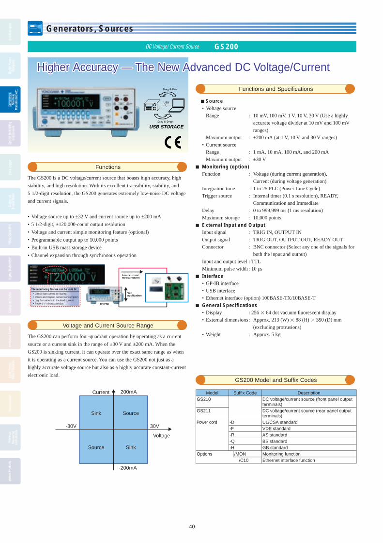
Generators, Sources
40
Gene
rato
rs,
Sour
ces,
Man
omet
ers
etc.
Osci
llosc
opes
Digi
tal P
ower
Anal
yzer
sGe
nera
tors
,Ge
nera
tors
,Ge
nera
tors
,So
urce
s,So
urce
s,So
urce
s,M
anom
eter
s et
c.M
anom
eter
s et
c.M
anom
eter
s et
c.
Optic
al M
easu
ring
Inst
rum
ents
Data
Log
ger
Clam
p-on
Pow
er M
eter
Hand
y Ca
libra
tor
Digi
tal M
ultim
eter
Clam
p-on
Tes
ter
Insu
latio
n Te
ster
Eart
h Te
ster
,Ot
her P
rodu
cts
Ther
mom
eter
Prec
isio
nM
easu
ring
Inst
rum
ents
Met
ers
Prod
ucts
Higher Accuracy — The New Advanced DC Voltage/Current Higher Accuracy — The New Advanced DC Voltage/Current
DC Voltage/ Current Source GS200
Functions and Specifi cations
Functions
The GS200 is a DC voltage/current source that boasts high accuracy, high
stability, and high resolution. With its excellent traceability, stability, and
5 1/2-digit resolution, the GS200 generates extremely low-noise DC voltage
and current signals.
• Voltage source up to ±32 V and current source up to ±200 mA
• 5 1/2-digit, ±120,000-count output resolution
• Voltage and current simple monitoring feature (optional)
• Programmable output up to 10,000 points
• Built-in USB mass storage device
• Channel expansion through synchronous operation
Voltage and Current Source Range
The GS200 can perform four-quadrant operation by operating as a current
source or a current sink in the range of ±30 V and ±200 mA. When the
GS200 is sinking current, it can operate over the exact same range as when
it is operating as a current source. You can use the GS200 not just as a
highly accurate voltage source but also as a highly accurate constant-current
electronic load.
-30V 30V
-200mA
200mA
Source Sink
Sink Source
Voltage
Current
GS200 Model and Suffi x Codes
The monitoring feature can be used to:• Check that current is flowing.• Check and inspect current consumption• Log fluctuations in the load current• Record V-I characteristics GS200
Vcc application
Load current measurement
Model Suffi x Code DescriptionGS210 DC voltage/current source (front panel output
terminals)GS211 DC voltage/current source (rear panel output
terminals)Power cord -D UL/CSA standard
-F VDE standard-R AS standard-Q BS standard-H GB standard
Options /MON Monitoring function/C10 Ethernet interface function
USB STORAGEDrag & Drop
Drag & Drop
USB Source • Voltage source
Range : 10 mV, 100 mV, 1 V, 10 V, 30 V (Use a highly
accurate voltage divider at 10 mV and 100 mV
ranges)
Maximum output : ±200 mA (at 1 V, 10 V, and 30 V ranges)
• Current source
Range : 1 mA, 10 mA, 100 mA, and 200 mA
Maximum output : ±30 V
Monitoring (option) Function : Voltage (during current generation),
Current (during voltage generation)
Integration time : 1 to 25 PLC (Power Line Cycle)
Trigger source : Internal timer (0.1 s resolution), READY,
Communication and Immediate
Delay : 0 to 999,999 ms (1 ms resolution)
Maximum storage : 10,000 points
External Input and Output Input signal : TRIG IN, OUTPUT IN
Output signal : TRIG OUT, OUTPUT OUT, READY OUT
Connector : BNC connector (Select any one of the signals for
both the input and output)
Input and output level : TTL
Minimum pulse width : 10 µs
Interface • GP-IB interface
• USB interface
• Ethernet interface (option) 100BASE-TX/10BASE-T
General Specifi cations • Display : 256 64 dot vacuum fl uorescent display
• External dimensions : Approx. 213 (W) 88 (H) 350 (D) mm
(excluding protrusions)
• Weight : Approx. 5 kg
BOOK_YMI130-EN 40 13.5.9, 10:45:18 AM

Generators, Sources
41
Gene
rato
rs,
Sour
ces,
Man
omet
ers
etc.
Osci
llosc
opes
Digi
tal P
ower
Anal
yzer
s
Gene
rato
rs,
Gene
rato
rs,
Gene
rato
rs,
Sour
ces,
Sour
ces,
Sour
ces,
Man
omet
ers
etc.
Man
omet
ers
etc.
Man
omet
ers
etc.
Optic
al M
easu
ring
Inst
rum
ents
Data
Log
ger
Clam
p-on
Pow
er M
eter
Hand
y Ca
libra
tor
Digi
tal M
ultim
eter
Clam
p-on
Tes
ter
Insu
latio
n Te
ster
Eart
h Te
ster
,Ot
her P
rodu
cts
Ther
mom
eter
Prec
isio
nM
easu
ring
Inst
rum
ents
Met
ers
Prod
ucts
Multi Channel Source Measure Unit GS820
Highly Accurate 2-Channel Voltage/Current Source Measure UnitHighly Accurate 2-Channel Voltage/Current Source Measure Unit
Features
The GS820 is a highly accurate and highly functional 2-channel
programmable DC voltage/current source that incorporates voltage/current
generation and measurement functions.
• Isolated 2-channel source and measurement function
• Source and measurement ranges: 7 V and 3.2 A or 18 V and 1.2 A
• Minute current ranges with 200-nA or 1-pA resolution
• Generate arbitrary waveforms consisting of up to 100,000 points at 100-µs
intervals
• Channel expansion through master-slave synchronization link
• Fast test speeds
• 16-bit digital I/O (model 765602)
Source and Measurement Range
Four-quadrant operation consisting of source operation (current source) and
sink operation (current sink) is available with ranges up to 7 V and 3.2 A or
18 V and 1.2 A.
The output and measurement resolutions are 5.5 digits.
-3.2
7-7-18
3.2
1.2
-1.218
Voltage (V)
Current (A)
Source
Source
Sink
Sink
Model and Suffi x code
USB STORAGEDrag & Drop
Drag & Drop
USB
2-channel display example (256 x 64 dot matrix display)
SourceFunction: Voltage or currentMode: DC or pulse (pulse width: 50 µs to 3,600 s)Sweep mode: Linear, logarithmic or program (up to 100,000 steps)Trigger source: External or internal timers 1 and 2 (period: 100 µs to 3600 s)Sweep start source: External or internal timers 1 and 2 (period: 100 µs to 3600 s)Source delay: 15 µ to 3600 sResponse characteristics: Normal or stableMeasurementFunction: Voltage, current, auto, voltmeter mode, ammeter mode or resistance meter modeIntegration time: 0.001 to 25 PLC (Power Line Cycle)Trigger source: External or internal timers 1 and 2 (period: 100 µs to 3600 s)Measure delay: 0 µs to 3600 sMeasurement data storage: Up to 100000 data pointsAverage: Moving average (average count: 2 to 256)Voltage sense: Two-wire system or four-wire systemAuto zero: Measure the internal zero reference every measurement and correct the measured valueNULL computation: Computes the difference with respect to the current measuredvalue or user-defi ned valueUser-defi ned computation: Computes user-defi ned equations in real-timeOperators: +[addition], -[subtraction], *[multiplication], /[division], ^ [exponentiation], % [mod], | [logic OR], & [logic AND], ! [negation], < <= > >= == != [comparison], = [substitution],Functions: ABS() [absolute value], SQRT() [square root], LN(), LOG() [logarithm], SIN(), COS(), TAN() [trigonometric functions], ASIN(), ACOS(), ATAN() [inverse trigonometric functions], SINH(), COSH(), TANH() [hyperbolic functions], RAND() (random number generation), EDGE() [logic change extraction], TRUNC(), FLOOR() [rounding to an integer], ISINF() [infi nity judgment], ISNAN [not-a-number judgment]Conditional statement: IF-THEN-ELSECommunication InterfaceGPIBElectrical and mechanical specifi cations: Conforms to IEEE St'd 488-1978Functional specifi cations: SH1, AH1, T6, L4, SR1, RL1, PP0, DC1, DT1, C0Protocol: Conforms to IEEE St'd 488.2-1987Address: 0 to 30RS232Electrical specifi cations: Conforms to EIA RS232Connection format: Point-to-pointTransmission mode: Full-duplexSynchronization mode: Start-stop synchronizationBaud rate: 9600, 14400, 19200, 38400, 57600, 115200 bpsUSBNumber of ports: 1Connector type: Type B connector (receptacle)Electrical and mechanical specifi cations: Conforms to USB Rev. 2.0Protocol: Mass storage class, USB-TMCEthernetNumber of Ethernet ports: 1Connector type: RJ-45 connectorElectrical and mechanical specifi cations: Conforms to IEEE 802.3Transmission system: 100BASE-TX/10BASE-TData rate: 100 Mbps or 10 MbpsProtocol: VXI-11 server, HTTP server, FTP server, DHCP client, and command socket
Functions
Model Suffi x Code Notes
765601GS820 Multi Channel Source Measure Unit Standard Model
765602GS820 Multi Channel Source Measure Unit Digital I/O Installed Model
Power cord
-D UL/CSA standard-F VDE standard
-R AS standard
-Q BS standard
-H GB standard
BOOK_YMI130-EN 41 13.5.9, 10:45:25 AM

Generators, Sources
42
Gene
rato
rs,
Sour
ces,
Man
omet
ers
etc.
Osci
llosc
opes
Digi
tal P
ower
Anal
yzer
sGe
nera
tors
,Ge
nera
tors
,Ge
nera
tors
,So
urce
s,So
urce
s,So
urce
s,M
anom
eter
s et
c.M
anom
eter
s et
c.M
anom
eter
s et
c.
Optic
al M
easu
ring
Inst
rum
ents
Data
Log
ger
Clam
p-on
Pow
er M
eter
Hand
y Ca
libra
tor
Digi
tal M
ultim
eter
Clam
p-on
Tes
ter
Insu
latio
n Te
ster
Eart
h Te
ster
,Ot
her P
rodu
cts
Ther
mom
eter
Prec
isio
nM
easu
ring
Inst
rum
ents
Met
ers
Prod
ucts
Combines High Accuracy and High Speed in a Single UnitCombines High Accuracy and High Speed in a Single Unit
The GS610 is a highly accurate and highly functional pro gram ma ble
volt age/current source that incorporates voltage/current generation and
mea sure ment functions. The maximum output voltage and current are
110 V and 3.2 A, respectively. Evaluation of over a wide range of ba sic
elec tri cal characteristics is possible, because the GS610 can operate as a
cur rent source or a current sink.
• Source and sink operation up to 110 V/3.2 A (four-quadrant op er a tion)
• Basic accuracy: ±0.02% *1
• Sweep output at up to 100 µs intervals
• Comes with abundant sweep patterns (linear, logarithmic, and ar bi trary)
• Stores up to 65535 points of source measure data in the internal memory
• Easy fi le operation with the USB storage function
• Remote control and FTP using Web server function (Optional)
*1: DC voltage gen er a tion
Features
Voltage/Current Generation and Measurement Range
Four-dimensional op er a tion with source op er a tion (cur rent source) and
sink op er a tion (cur rent sink) is pos si ble at up to 110 V, 3.2 A, and 60 W.
The output and mea sure ment resolutions are 5.5 digits.
Voltage generation/mea sure ment range: 200mV to 110 V
Current generation/mea sure ment range: 20 µA to 3.2 A
Maximum output current:
±3.2 A (at an output voltage of ±12 V or less)
±2 A (at an output voltage of ±30 V or less)
±1 A (at an output voltage of ±60 V or less)
±0.5 A (at an output voltage of ±110 V or less)
3.2
2.0
1.0
0.5
-0.5
0 12-12 30-30 60-60 110-110
-1.0
-2.0
-3.2
Voltage (V)
Current (A)
Source
Source
Sink
Sink
Source Measure Unit GS610
USB STORAGEDrag & Drop
Drag & Drop
USB
Model and Suffi x code
Functions
Model Suffi x Codes Description
765501 GS610 Source Measure Unit
Power cord
-D UL/CSA standard
-F VDE standard
-R AS standard
-Q BS standard
-H GB standard
Option /C10 Ethernet interface
Function • Generation Generation function : Voltage or current Generation mode : DC or pulse Sweep mode : Linear, logarithmic or program (up to 65,535
steps) • Measurement Measurement function : DC voltage, DC current and resistance Measurement data storage : Up to 65,535 data points Average : Block average or moving average (Specifi ed count: 2 to 256) • Trigger Trigger mode : Internal, external and immediate • Time setting Pulse width : 100 µs to 3,600 s, 1 µs resolution Period time : 1 ms to 3,600 s, 1 µs resolution (during source and measure operation) 100 µs to 3,600 s, 1 µs resolution (during source-only operation) Source delay : 1 µs to 3,600 s, 1 µs resolution Measurement delay : 1 µs to 3,600 s, 1µs resolution Integration time : 250 µs, 1 ms, 4 ms, 16.6 ms/20 ms,100 ms,
200 ms (auto detect from the power supply frequency
when the power is turned ON for 16.6 ms/20 ms) • Computation function Operators : +[addition], -[subtraction], *[multiplication], /[division] and
^ [exponentiation] Functions : ABS(), EXP(), LN(), LOG(), SQRT(), SIN(), COS(), TAN(),
ASIN(), ACOS(), ATAN(), SINH(), COSH(), TANH(), RAND()
External Input/Output • Synchronization signal input/output (TRIG, SWEEP, CTRL IN and
OUT) (BNC) • External input/output (D-Sub 15-pin) • GP-IB interface • RS-232 interface • USB interface • Ethernet interface (option) 100BASE-TX/10BASE-T
Internal memory ROM : 4 MB Area for storing setup and output pattern fi les RAM : 4 MB Area for storing the measured results
(cleared when the power is turned OFF)
Display : 256 64 dot vacuum fl uorescent display
External dimensions : Approx. 213 (W) 132 (H) 400 (D) mm (excluding protrusions)
Weight : Approx. 7 kg
BOOK_YMI130-EN 42 13.5.9, 10:45:31 AM

Generators, Sources
43
Gene
rato
rs,
Sour
ces,
Man
omet
ers
etc.
Osci
llosc
opes
Digi
tal P
ower
Anal
yzer
s
Gene
rato
rs,
Gene
rato
rs,
Gene
rato
rs,
Sour
ces,
Sour
ces,
Sour
ces,
Man
omet
ers
etc.
Man
omet
ers
etc.
Man
omet
ers
etc.
Optic
al M
easu
ring
Inst
rum
ents
Data
Log
ger
Clam
p-on
Pow
er M
eter
Hand
y Ca
libra
tor
Digi
tal M
ultim
eter
Clam
p-on
Tes
ter
Insu
latio
n Te
ster
Eart
h Te
ster
,Ot
her P
rodu
cts
Ther
mom
eter
Prec
isio
nM
easu
ring
Inst
rum
ents
Met
ers
Prod
ucts
GS Series Accessory Software 765670 Curve Tracer Software for the GS series
Features
Simple system confi guration, easy connection, compact and lightThis system is confi gured by connecting the GS series Source Measure Unit to a PC that contains the 765670 Curve Tracer Software via USB. You can perform high speed, high-accuracy curve tracing despite its compact size, light weight, And simple system confi guration.
Real-time, High-Speed DrawingThe GS series is high-speed communication and sweep features allow high-speed graph update rate up to 25 pages/s(GS820). You can use the real-time curve tracer with comfort.
Field of Applications• Discrete semiconductors such as transistors and diodes• Analog ICs such as voltage regulators and op- amps• MOS logic and other digital ICs• LEDs and other optical devices
• Solar battery cells
Drawing Speed (times/s; reference values)
Plot PointsModel Number
GS610 GS82020 20 2550 10 16100 5 11200 3 6
Measurement conditions: Using Core2Duo CPU, 1.5 GHz, USB 2.0, and LabVIEWMeasurement integration time: 0.001 PLC for GS820 / 250 µs for GS610
http://tmi.yokogawa.com/products/generators-sources/source-measure-units/765670-curve-tracer-software/
• Graph drawing: Voltage vs. current, voltage vs. voltage, gain vs. voltage, voltage vs. timestamp,
current vs. voltage, current vs. current, gain vs. current, current vs. timestamp Sweep axis: Voltage source or current source Measurement axis: Voltage measurement or current measurement Parameter: Voltage source or current source Sweep shape: Ramp (linear or log), triangle (linear or log), rectangle Sweep points: 5, 10, 20, 50, 100, 200, 1000 Scaling: Auto scale or fi xed scale Averaging count: 2 to 100• Analysis feature: Cursor, zoom & scroll, reference curve designation• File operations: CSV data storage and loading, graphic image storage, panel image storage,
setup storage and recall
Specifi cations
Product Overview
This product is a high-speed, high-accuracy real-time V-I curve tracer that consists of the GS series Source Measure Unit and the 765670 Curve Tracer Software. It is particularly well-suited to DC parametric tests of minute signals.
Examples of Measurements of Characteristics
FET VDS-ID characteristics
G
S
D
AVGS
Connection diagram
Measurement results
0 250m 750m 1 1.25 1.5 1.75 2 2.25 2.5 2.75 3 3.25 3.5 3.75 4 4.25 4.5 4.75 5Sweep (V)
Mea
sure
(A
)
8.5m
8.5m
7.5m
7m
6.5m
6m
5.5m
5m
4.5m
4m
3.5m
3m
2.5m
2m
1.5m
1m
500µ0
0V-0.1V-0.2V-0.3V
VDS
ID
Channel 1V source
Channel 2V sweep
I measurement
System configuration illustration
USB
GS820 PC
USB
USB
GS610 PC
BOOK_YMI130-EN 43 13.5.9, 10:45:34 AM

Generators, Sources
44
Osci
llosc
opes
Digi
tal P
ower
Anal
yzer
sGe
nera
tors
,So
urce
s,M
anom
eter
s et
c.
Optic
al M
easu
ring
Inst
rum
ents
Data
Log
ger
Clam
p-on
Pow
er M
eter
Hand
y Ca
libra
tor
Digi
tal M
ultim
eter
Clam
p-on
Tes
ter
Insu
latio
n Te
ster
Eart
h Te
ster
,Ot
her P
rodu
cts
Ther
mom
eter
Prec
isio
nM
easu
ring
Inst
rum
ents
Met
ers
Prod
ucts
Gene
rato
rs,
Sour
ces,
Man
omet
ers
etc.
Osci
llosc
opes
Digi
tal P
ower
Anal
yzer
sGe
nera
tors
,Ge
nera
tors
,Ge
nera
tors
,Ge
nera
tors
,So
urce
s,So
urce
s,So
urce
s,So
urce
s,M
anom
eter
s et
c.M
anom
eter
s et
c.M
anom
eter
s et
c.M
anom
eter
s et
c.
Optic
al M
easu
ring
Inst
rum
ents
Data
Log
ger
Clam
p-on
Pow
er M
eter
Hand
y Ca
libra
tor
Digi
tal M
ultim
eter
Clam
p-on
Tes
ter
Insu
latio
n Te
ster
Eart
h Te
ster
,Ot
her P
rodu
cts
Ther
mom
eter
Prec
isio
nM
easu
ring
Inst
rum
ents
Met
ers
Prod
ucts
AC Standard Source with Improved Performance and Usability
AC Voltage Current Standard 2558A
Functions and Specifications
Features
The wide output ranges of 1.00mV to 1200.0 V AC and 1.00
mA to 60.00 A AC mean that the 2558A is the instrument
of choice for the cost effective calibration of AC analog
meters.
• Wide output range AC voltage : 1.00 mV to 1200.0V AC current : 1.00 mA to 60.00 V• High accuracy AC voltage : 0.04% AC current : 0.05%• High output stability : ±50 ppm/h• Wide frequency range : 40 to 1000 Hz Accuracy : ±50 ppm• Intuitive operation with dials for setting each digit• Sweep function : 16/32/64 sec. (selectable)• Output divider function (Divided output of the main setting)• Direct readout of the deviation (Displays the deviation from the main
setting)
Functions and Specification
Output
Range Output Range Guaranteed Accuracy Range
100 mV 0 to 144.00 mV 1 to 120.00 mV
1 V 0 to 1.4400 V 0.01 to 1.2000 V
10 V 0 to 14.400 V 0.1 to 12.000 V
100 V 0 to 144.00 V 1 to 120.00 V
300 V 0 to 432.0 V 3 to 360.0 V
1000 V 0 to 1440.0 V 10 to 1200.0 V
100 mA 0 to 144.00 mA 1 to 120.00 mA
1 A 0 to 1.4400 A 0.01 to 1.2000 A
10 A 0 to 14.400 A 0.1 to 12.000 A
50 A 0 to 72.00 A 0.5 to 60.00 A
Accuracy (180 days) 1 to 10% output of range ±(% of range) Voltage 50/60 Hz : 0.013 40 to 400 Hz : 0.015 400 to 1000 Hz : 0.030 Current 50/60 Hz : 0.014 40 to 400 Hz : 0.016 400 to 1000 Hz : 0.032 10 to 120% output of range ±(% of setting + % of range) Voltage 50/60 Hz : 0.03 + 0.01 40 to 40 0Hz : 0.05 + 0.01 400 to 1000 Hz : 0.10 + 0.02 Current 50/60 Hz : 0.04 + 0.01 40 to 400 Hz : 0.06 + 0.01 400 to 1000 Hz : 0.12 + 0.02
2558A Model and Suffix Codes
Model Suffix Code Description
2558A AC Voltage Current Standard
Power code -D UL/CSA standard, PSE
-F VDE standard
-R AS standard
-Q BS standard
-H GB standard
-N NBR standard
Option /C1 GP-IB interface
2558A
Stability : ±(20 ppm of setting + 30 ppm of range)/hDistortion factor Voltage : 0.07% or less Current : 0.18% or lessFrequency range Internal : 50 / 60 / 400 Hz / VAR VAR: 40 to 1000 Hz (0.001 Hz resolution) External : EXT1/EXT2 (Use the terminals for synchronized operations) FREQUENCY METER : MIN/MAX 20 to 1000 Hz (0.001 Hz resolution) Sweep, output divider and deviation functions are used
for the frequency.Sweep Target : Voltage / Current / Frequency Speed : Approx. 16/32/64 sec. selectableOutput divider Target : Voltage / Current / Frequency Denominator range : m4 to 15 Numerator range : n0 to 15 (n ≤ m)Deviation Target : Voltage / Current / Frequency Variable range: ±20.00% Operation : Two dials
Resolution of the first dial: 0.2% of the main setting
Resolution of the second dial: 0.01% of the main setting
Deviation preset: OFF / 0 / 2% / 5%Output terminalType Voltage : Plug-in terminal (safety terminal) Current : Binding post Selectable LO terminal to earth or floating Max. floating voltage to earth: 12 VpkInterface : USB interface (for PC connection) : Ethernet : GP-IB interface (optional)Warm-up time : Approx. 30 minutesOperating environment Temperature : 5 to 40ºC Humidity : 20 to 80%RH (no condensation)Rated power supply voltage : 100 to 120 VAC / 200 to 240 VACRated power supply frequency : 50/60 HzMax. power consumption : 200 VAWeight : Approx. 20 kgDimensions : 426(W) x 132(H) x 400(D) mm
YMI130-EN_CS3.indb 44 13.5.9 10:56:34 AM

Generators, Sources
45
Gene
rato
rs,
Sour
ces,
Man
omet
ers
etc.
Osci
llosc
opes
Digi
tal P
ower
Anal
yzer
s
Gene
rato
rs,
Gene
rato
rs,
Gene
rato
rs,
Sour
ces,
Sour
ces,
Sour
ces,
Man
omet
ers
etc.
Man
omet
ers
etc.
Man
omet
ers
etc.
Optic
al M
easu
ring
Inst
rum
ents
Data
Log
ger
Clam
p-on
Pow
er M
eter
Hand
y Ca
libra
tor
Digi
tal M
ultim
eter
Clam
p-on
Tes
ter
Insu
latio
n Te
ster
Eart
h Te
ster
,Ot
her P
rodu
cts
Ther
mom
eter
Prec
isio
nM
easu
ring
Inst
rum
ents
Met
ers
Prod
ucts
Digital Multimeters 7561/7562
Temperature Measuring Instrument 7563
6.5 Digits Digital Multimeter
7561/7562Digital Multimeters
• High accuracy (DC voltage-based accuracy) ±0.0045% of reading ± 15 digits• Fast sampling at 333 times/s• Large capacity buffer memory: up to 8000 data items IC memory card usable• GP-IB interface (standard)
7561/7562 Specifi cations
• DC voltage (DCV) Range: 200 mV to 1000 V• DC current (DCA) Range: 2 mA to 2000 mA• AC voltage (ACV)(7562 only) Range: 200 mV to 700 V• AC current (ACA)(7562 only) Range: 2 mA to 2000 mA• Resistance measurement (OHM, 2 W/4 W) Range: 200 Ω to 200 MΩ• Maximum indication: 1999999• External dimensions: approx. 213 (W) × 88 (H) × 330 (D) mm• Weight: approx. 3 kg
7563Digital Thermometer, 6.5 Digits
• Thermometer has a 6.5-digits display Twelve types of TC’s and four types of RTD’s• Basic accuracy in temperature
measurement: 0.006% (TC)• Basic accuracy in DCV measurement: 0.0045% (2000 mV range)• Basic accuracy in resistance mea sure ment: 0.006% (2000 Ω range)• Number of sampling times: up to 100 times/s (4.5 digits)
7563 Specifi cations
Maximum display: ±1999999Resolution:Voltage 100 nV Resistance 100 µΩ Thermocouple 0.1°C RTD 0.01°CReference junction compensation ac cu ra cy: ±0.2°CVarious computation functionsSoftware calibration functionMemory function• Internal memory up to 1000 data items• IC memory up to 8000 data itemsCommunication function: GP-IBAnalog output (optional): code /DA specifi edPower consumption: 20 VAExternal dimensions: 213 (W) × 88 (H) × 350 (D) mmWeight: approx. 3 kg
Precision Digital Thermometer
Digital Resistance Meter 7556
7556• High-speed measurement (2.8 ms)• High accuracy: ±(0.006% of reading + 3 digits)• High resolution: 5.5 digits• Wide range: 1 Ω range to 100 MΩ range• Full remote control through serial (RS-232) or GP-IB interface• Software-based calibration function• Advanced contact check function
7556 Specifi cations
Range: 1 Ω, 10 Ω, 100 Ω, 1 kΩ, 10 kΩ, 100 kΩ, 1 MΩ, 10 MΩ, 100 MΩ
Resolution: Deviation display 755601: -99.99% to 19.99% or -99.9% to 199.9% (selectable) 755611: -99.999% to 19.999% or -99.99 to 199.99% (selectable) Absolute value display 755601: 100 µΩ (at 1 Ω range) 755611: 10 µΩ (at 1 Ω range)Measurement time: Normal mode: 60 Hz power supply: 19.9 ms 50 Hz power supply: 23.2 ms Fast mode: 5.7 ms High-speed mode: 2.8 msAccuracy (at 1 kΩ range, 23±5°C in normal mode) 755601: ±(0.015% of reading + 1 digit) 755611: ±(0.006% of reading + 3 digits)Contact check function Check level: 1 Ω to 30 Ω (Selectable) Execute checks before or after measurement (selectable) Check current: 50 mA Contact check error message with display panel and handler interface Measured current abnormality detection function (Detect measured current abnormality caused by a
contact error)Comparator function (both Hi and Lo) Deviation setting range 755601: -9.99% to 9.99% or -99.9% to 99.9% (selectable) 755611: -9.999% to 9.999% or -99.99% to 99.99% (selectable) Absolute value setting range 755601: 0.0000 Ω to 1.2000 Ω 755611: 0.00000 Ω to 1.20000 Ω
The 7556 is designed to be mounted on a taping machine.* When you use the 7556 for any purpose other than a production line, you need to be careful.
Please read the specifi cations carefully.
High-Speed Digital Resistance Meter for Production Line of Fixed Chip Resistors
YMI130-EN_40-43_45-47.indd 45 13.5.9, 3:39:55 PM

Generators, Sources
46
Gene
rato
rs,
Sour
ces,
Man
omet
ers
etc.
Osci
llosc
opes
Digi
tal P
ower
Anal
yzer
sGe
nera
tors
,Ge
nera
tors
,Ge
nera
tors
,So
urce
s,So
urce
s,So
urce
s,M
anom
eter
s et
c.M
anom
eter
s et
c.M
anom
eter
s et
c.
Optic
al M
easu
ring
Inst
rum
ents
Data
Log
ger
Clam
p-on
Pow
er M
eter
Hand
y Ca
libra
tor
Digi
tal M
ultim
eter
Clam
p-on
Tes
ter
Insu
latio
n Te
ster
Eart
h Te
ster
,Ot
her P
rodu
cts
Ther
mom
eter
Prec
isio
nM
easu
ring
Inst
rum
ents
Met
ers
Prod
ucts
Pressure Standard MC100
Manometers MT210/MT210F/MT220/MT10
MT210FDigital Manometer
• High accuracy: ±(0.01% of read ing + 3 dig its) (130 kPa range gauge model)
• Select from three measurement modes: nor mal speed, medium speed, and high speed
• D/A conversion output, com par a tor out put, and external trigger input (op tion al)
• Both gases and liquids mea sur able• External attachable battery pack (op tion al)
MT210F Series Specifi cations
• Measuring range (gauge pres sure: pos i tive) 0 to 10 kPa, 130 kPa, 700 kPa and 3000 kPa Measuring range (gauge pres sure: negative) -80 to 0 kPa, -10 to 0 kPa• Measuring range (absolute pres sure) 0 to 130 kPa abs• Accuracy (for 0 to 10 kPa range model) ±(0.01% of reading + 0.015% of full
scale) (at positive pressure)• Response time (0 to 130 kPa range mod el,
at high speed mode) 50 msec max.• Readout update interval (at me di um and
high speed mode) 100 msec• Resolution 0 to 10 kPa range model: 0.0001 kPa 0 to 130 kPa range model: 0.001 kPa 0 to 700 kPa range model: 0.01 kPa 0 to 3000 kPa range model: 0.01 kPa• Maximum allowable input (for gauge
pressure pos i tive) 0 to 10 kPa range model: 500 kPa gauge 0 to 130 kPa range model: 500 kPa gauge 0 to 700 kPa range model: 3000 kPa gauge 0 to 3000 kPa range model: 4500 kPa gauge• Pressure display units (selectable): psi, inH2O, inHg, kPa, kgf/cm2, mmH2O, mmHg• External dimensions: 213 (W) × 132 (H) × 350 (D) mm• Weight Approx. 6.5 kg (0 to 130 kPa range mod el)
Fast Response Digital Manometer
MT210Digital Manometer
• High accuracy: ±(0.01% of reading + 3 dig its) (130 kPa range gauge model)
• A wide range pressures, from a low differential pressure of 1 kPa to a high gauge pres sure of 3000 kPa, and ab so lute pres sure of 130 kPa
• D/A conversion output, comparator out put, and external trig ger input (op tion al)
• Both gases and liquids measurable• External attachable battery pack (op tion al)
MT210 Series Specifi cations
• Measuring range (gauge pressure: pos i tive) 0 to 10 kPa, 130 kPa, 700 kPa and 3000 kPa Measuring range (gauge pressure: negative) -80 to 0 kPa, -10 to 0 kPa• Measuring range (absolute pressure) 0 to 130 kPa abs• Measuring range (differential pressure) 0 to 1 kPa, 10 kPa, 130 kPa and 700 kPa• Accuracy (for 0 to 10 kPa range model) ±(0.01% of reading + 0.015% of full
scale) (at positive pres sure)• Resolution 0 to 1 kPa range model: 0.00001 kPa 0 to 10 kPa range model: 0.0001 kPa 0 to 130 kPa range model: 0.001 kPa 0 to 700 kPa range model: 0.01 kPa 0 to 3000 kPa range model: 0.01 kPa• Maximum allowable input (for gauge
pressure positive) 0 to 10 kPa range model: 500 kPa gauge 0 to 130 kPa range model: 500 kPa gauge 0 to 700 kPa range model: 3000 kPa gauge 0 to 3000 kPa range model: 4500 kPa gauge• Pressure display units (selectable): psi, inH2O, inHg, kPa, kgf/cm2, mmH2O,
mmHg• External dimensions: 213 (W) × 132 (H) × 350 (D) mm• Weight Approx. 6.5 kg (0 to 130 kPa range mod el)
Precision Digital Manometer
MC100Pneumatic Pressure Standard
• High accuracy: ±0.05% of full scale• Output rang es and res o lu tion 0 to 200 kPa (resolution 0.01 kPa) 0 to 25 kPa (resolution 0.001 kPa)• Functions useful for in stru ment cal i bra tion Divider output, auto-step out put, and sweep
output• Excellent temperature co ef fi cient Zero point: ±0.003% of full scale/°C Span: ±0.002% of full scale/°C
MC100 Series Specifi cations
• Supply pressure 0 to 200 kPa range model: 280 kPa ±20 kPa 0 to 25 kPa range model: 50 kPa ±10 kPa• Accuracy ±0.05% of full scale (at 23°C ±3°C)• Output noise: ±0.02% of full scale• Effect of mounting orientation Forward/backward incline of 90° 0 to 200 kPa range model: ±0.01% of
full scale 0 to 25 kPa range model:
Pneumatic Pressure Standard
±0.1% of full scale Sideways incline of 30° 0 to 200 kPa range model: ±0.2% of
full scale 0 to 25 kPa range model: ±2.5% of
full scale• Pressure display units (se lect able): kPa, kgf/cm2, mmH2O, mmHg kPa, psi, inH2O, inHg• External dimensions: 213 (W) × 132 (H) × 400 (D) mm• Weight: approx. 9.5 kg
YMI130-EN_40-43_45-47.indd 46 13.5.9, 3:40:02 PM

Generators, Sources
47
Gene
rato
rs,
Sour
ces,
Man
omet
ers
etc.
Osci
llosc
opes
Digi
tal P
ower
Anal
yzer
s
Gene
rato
rs,
Gene
rato
rs,
Gene
rato
rs,
Sour
ces,
Sour
ces,
Sour
ces,
Man
omet
ers
etc.
Man
omet
ers
etc.
Man
omet
ers
etc.
Optic
al M
easu
ring
Inst
rum
ents
Data
Log
ger
Clam
p-on
Pow
er M
eter
Hand
y Ca
libra
tor
Digi
tal M
ultim
eter
Clam
p-on
Tes
ter
Insu
latio
n Te
ster
Eart
h Te
ster
,Ot
her P
rodu
cts
Ther
mom
eter
Prec
isio
nM
easu
ring
Inst
rum
ents
Met
ers
Prod
ucts
Digital Manometer For Effi cient Field Calibration Handheld Digital Manometer
MT10Mini-Manometer
• Compact and lightweight (approx. 700 g), bat tery-operated
• High reliability (silicon res o nant sensor adopt ed)
• Accuracy: ±(0.04% of rdg + 0.03% of FS) for 130 kPa model
• Three models for 130 kPa, 700 kPa, and 3000 kPa (gauge pressure)
• Data hold function• RS-232-C interface• Comes with carrying case
MT220Digital Manometer
• The de facto standard of fi eld celibrators for pressure and ditferential pressure transmitters
• High accuracy: ±(0.01% of reading + 3 dig its) (130 kPa range gauge model)
• DCV/DCA measurement function (DMM function)
• 24 VDC power supply for driving the transmitter
• % display, error display, and mea sured data mem o ry
• D/A conversion output, com par a tor out put, and ex ter nal trigger input (op tion al)
• Both gases and liquids mea sur able• External attachable battery pack (optional)
MT10 Series Specifi cations
• Type of pressure: gauge• Three measuring ranges 0 to 130 kPa, 0 to 700 kPa, and 0 to 3000 kPa• Measurement display range: -2.5 to 110% of FS• Accuracy: 0 to 130 kPa range model ±(0.04% of rdg + 0.03% of FS) 0 to 700 kPa and 0 to 3000 kPa range
mod els ±0.1% of FS• Resolution 0 to 130 kPa range model: 0.01 kPa 0 to 700 kPa range model: 0.1 kPa 0 to 3000 kPa range model: 1 kPa• Maximum allowable input 0 to 130 kPa range model: 500 kPa 0 to 700 kPa range model: 1000 kPa 0 to 3000 kPa range model: 4500 kPa• Effect of temperature Zero: ±0.02% of FS/10°C or less Span: ±0.02% of FS/10°C or less• Pressure display units (specifi ed at shipment) kPa, kgf/cm2, mmH2O, mmHg, Psi, inH2O, inHg• External dimensions: Approx. 72 (W) × 174 (H) × 60 (D) mm (excluding input connections)• Weight: Approx. 700 g (including battery)
MT220 Series Specifi cations
• Measuring range (gauge pressure: pos i tive) 0 to 10 kPa, 130 kPa, 700 kPa and 3000 kPa Measuring range (gauge pressure: negative) -80 to 0 kPa, -10 to 0 kPa• Measuring range (absolute pressure) 0 to 130 kPa abs• Accuracy (for 0 to 10 kPa range model) ±(0.01% of reading + 0.015% of full
scale) (at positive pres sure)• Resolution 0 to 10 kPa range model: 0.0001 kPa 0 to 130 kPa range model: 0.001 kPa 0 to 700 kPa range model: 0.01 kPa 0 to 3000 kPa range model: 0.01 kPa• Maximum allowable input (for gauge
pressure positive) 0 to 10 kPa range model: 500 kPa gauge 0 to 130 kPa range model: 500 kPa gauge 0 to 700 kPa range model: 3000 kPa gauge 0 to 3000 kPa range model: 4500 kPa gauge• Pressure display units (selectable): psi, inH2O, inHg, kPa, kgf/cm2, mmH2O, mmHg• Measurement range of DCV/DCA
mea sure ment function 0 to ±5.25 V 0 to ±21 mA• Accuracy of DCV/DCA measurement
func tion (6 months after calibration) ±(0.05% of reading + 3 digits)• 24 VDC output 24 ± 1 VDC, 30 mA max.• External dimensions: 213 (W) × 132 (H) × 350 (D) mm• Weight Approx. 7.0 kg (0 to 130 kPa range model)
YMI130-EN_40-43_45-47.indd 47 13.5.9, 3:40:05 PM

Optical Measuring Instruments
48
Optic
al M
easu
ring
Inst
rum
ents
Osci
llosc
opes
Digi
tal P
ower
Anal
yzer
sGe
nera
tors
,So
urce
s,M
anom
eter
s et
c.
Optic
al M
easu
ring
Optic
al M
easu
ring
Optic
al M
easu
ring
Inst
rum
ents
Inst
rum
ents
Inst
rum
ents
Data
Log
ger
Clam
p-on
Pow
er M
eter
Hand
y Ca
libra
tor
Digi
tal M
ultim
eter
Clam
p-on
Tes
ter
Insu
latio
n Te
ster
Eart
h Te
ster
,Ot
her P
rodu
cts
Ther
mom
eter
Prec
isio
nM
easu
ring
Inst
rum
ents
Met
ers
Prod
ucts
High Performance Optical Spectrum Analyzers Meeting Measurement Needs High Performance Optical Spectrum Analyzers Meeting Measurement Needs in a Broad Range of Applicationsin a Broad Range of Applications
Optical Spectrum Analyzer AQ6370 Series
• Best-in-class optical performance · High wavelength resolution and high dynamic range · High sensitivity · Free-space optical input• Excellent measurement throughput · High-speed spectrum measurement · High-speed remote interface · High resolution and wide bandwidth batch measurement• More user-friendly · USB interface available For mouse, keyboard, and external storage devices such as a memory
device and hard disc drive (HDD). · Trace zooming function · More than 10 waveform analysis functions available• Support for creating an automatic measurement system · GP-IB, RS-232C, and Ethernet interfaces available Support for the remote commands and formats of the AQ6317 series · Macro programming function available• Wavelength calibration reference light source or alignment light
source available• PC emulation and remote control software (option)
Three Models Converting a Wide Wavelength from 350 nm to 2400 nm
AQ6370C (600 to 1700 nm)Standard model optimized to the wavelengths often used in telecommunication applications AQ6373 (350 to 1200 nm)Model for short-wavelength including visible light (VIS) AQ6375 (1200 to 2400 nm)Model for long wavelength over 2 µm commonly used in the near-infrared range
Features
Environmental Measurement ApplicationInformation & Communication ApplicationBiomedical Application
Example of a Configuration of a Scanning Confocal Microscope System
Cell
Fluorescence from a cell
Camera
Laser
Fluorescence Microscope
Model CSU10 Confocal Scanner Unit
Z-axis Drive
Image MonitorImage Processing
Unit
High Performance Filter
TX Terminal
1
2
3
4
5
n
1
2
3
4
5
6
Optical AMP
OADM
RX Terminal
Optical Fiber
DEMUXMUX
100km~ 100km~ 100km~
DWDM Transmission System
Optical AMP
OADM
Amplified
Example of a Configuration of a Dense Wavelength Division Multiplexing (DWDM) Optical Communication System
Short Wavelength
Long Wavelength
400 600 1000 1200 1500 1700 2000 2400wavelength
(nm)
Main Optical Applications and Wavelength Bands Used
Visible Light Range
AQ6370C
AQ6375
AQ6373
Example of a Configuration of Simultaneous Multi-Wavelength Measurement of Gases Using the CDRS Technique
Detecting Gases Using Gas-SpecificLight Absorption Characteristics
CRDS OpticalCoupler
Laser 1
Circulator
Fiber Grating
WDMCoupler
Fiber Loop
1
2
Laser 2
Medical Treatment – Biology – Information & Communication – Environmental Analysis – Sensing – Material Processing, etc.
OpticalFiber
OpticalFiber
OpticalFiber
• Evaluating the performance of high performance filers for a visible light laser and fluorescence extraction
• Evaluating the performance of optical components, such as a laser, optical multiplexer, optical demultiplexer and optical amplifier, as well as the system as a whole
• Evaluating the performance of optical components such as a laser and grating
• Evaluating the light absorption characteristics of gases
Optical Applications
Today, optical technology is used in a wide variety of applications, which include biomedical application and environmental measurement, as well as information and communication, where demand for broadband connectivity is growing rapidly, driven by the popularity of the Internet, IP telephony, and video streaming. Yokogawa’s optical spectrum measurement technology contributes to the development of such optical applications.
AQ6370 Series of Optical Spectrum Analyzers Common Specifi cations
Item Specifi cations
Electrical interface GP-IB 2 (standard/for external controller), RS-232, Ethernet, USB, PS/2 (keyboard), SVGA output, analog output port, trigger input port, trigger output port
Remote control *GP-IB, RS-232, Ethernet (TCP/IP)AQ6317 series compatible commands (IEEE488.1) and IEEE488.2
Data storageInternal storage: 128 MB or more, Internal memory: 64 traces, 64 programs, 3 template lines, External storage: USB storage (memory/HDD), FAT32 format File types: CSV (text), Binary, BMP, TIFF
Display ** 10.4-inch color LCD (Resolution: 800 600)
Printer Built-in thermal printer (Factory installed option)
External dimensions Approx. 426 (W) 221 (H) 459 (D) mm (excluding protector and handle)
Mass AQ6370C: Approx. 19 kg, AQ6373: Approx. 20 kg, AQ6375: Approx. 27 kg (without printer option)
Power supply 100 to 240 VAC, 50/60 Hz, approx. 150 VA
Environmental conditionsPerformance guarantee temperature range: + 18 to + 28°C, Operating temperature range: +5 to +35°C, Storage temperature range: -10 to +50°C, Humidity: ≤80 %RH (no condensation)
*: Some AQ6317 series commands may not be compatible due to changes in the specifi cations or functions of models.
**: Liquid crystal display may include a few defective pixels (within 0.002% with respect to the total number of pixels including RGB). There may be a few pixels on the liquid crystal display that do not emit all the time or remain ON all the time. These are not malfunctions.
BOOK_YMI130-EN 48 13.5.9, 10:45:55 AM

Optical Measuring Instruments
49
Optic
al M
easu
ring
Inst
rum
ents
Osci
llosc
opes
Digi
tal P
ower
Anal
yzer
s
Gene
rato
rs,
Sour
ces,
Man
omet
ers
etc.
Optic
al M
easu
ring
Optic
al M
easu
ring
Optic
al M
easu
ring
Inst
rum
ents
Inst
rum
ents
Inst
rum
ents
Data
Log
ger
Clam
p-on
Pow
er M
eter
Hand
y Ca
libra
tor
Digi
tal M
ultim
eter
Clam
p-on
Tes
ter
Insu
latio
n Te
ster
Eart
h Te
ster
,Ot
her P
rodu
cts
Ther
mom
eter
Prec
isio
nM
easu
ring
Inst
rum
ents
Met
ers
Prod
ucts
Redefi ning Optical Spectrum Measurement ExcellenceRedefi ning Optical Spectrum Measurement Excellence
• Measurement wavelength range: 600 to 1700 nm• Wavelength accuracy: ±0.01 nm (High performance model), ±0.02 nm
(standard model) • Measurement data point: 101 to 50001• Wavelength resolution setting: 0.02 to 2.0 nm• Level sensitivity: -90 dBm (1300 to 1620 nm, resolution: 0.05nm or wider, sensitivity: HIGH3)• Maximum input power: +20 dBm (Per channel, full span)• Close-in dynamic range (at 1523nm): 45 dB ( ±0.1 nm from peak, resolution: 0.02 nm) 58 dB (±0.2 nm from peak, resolution: 0.02 nm) 50 dB (±0.2 nm from peak, resolution: 0.05 nm) 64 dB (±0.4 nm from peak, resolution: 0.05 nm) 73 dB (±1.0 nm from peak, resolution: 0.05 nm) 45 dB (±0.2 nm from peak, resolution: 0.1 nm) 60 dB (±0.4 nm from peak, resolution: 0.1 nm)• Applicable fi ber: SM (9.5/125 µm), GI (50/125 µm, 62.5/125 µm)
Basic Specifi cations
• World Class Optical Performance & Flexibility High wavelength resolution: 0.01 nm Wide close-in dynamic range: 78dB typ. Single and multimode fi ber test capability (up to GI 62.5/125µm)• Improved Measurement Throughput Double-speed mode Fast measurement and fast data transfer• Enhanced User Friendliness USB for Mouse, keyboard, and external storage devices Bright 10.4” LCD Trace zoom capability Various built-in analysis functions• Expedites Development of Automated Test Systems Supports GP-IB, RS-232C, and Ethernet interfaces Compatible with SCPI and supports AQ6317 series remote commands Built-in simple macro programming function• Includes Wavelength Calibration Source• AQ6370 Viewer: Emulation/Remote control software (Optional)
Features
Example of the dynamic range
Peak±1.0nm, Resolution setting 0.05 nm, High dynamic mode: ON, High performance model
DWDM signal measurement
DWDM chan nels allocated at 50GHz spac- ing can be mea sured and analyzed.
Model Number and Suffi x Codes
Measurement speed
Key & Command response
Data transfer Speed(in comparison with AQ6317C Optical spectrum Analyzer)
Note. AQ6370 Viewer contains the AQ6370C Viewer.
The AQ6370C Viewer is a PC application software that has the same user interface and functions as the AQ6370C so that you can easily display and analyze waveform data acquired by the AQ6370C.
• Viewer function Trace data fi les saved
on the AQ6370C can be retrieved and analyzed on a PC.
• Remote Control function
The remote control allows you to set measurement conditions and to execute a measurement on AQ6370C Optical Spectrum Analyzer from anywhere on the Ethernet network.
• File Transfer function Files can be exchanged between AQ6370C and PC.
10x
100x
100x
Improved Measurement Throughput
World-class optical performance
AQ6370 Viewer Emulation/Remote Control Software (Optional)
Enhanced User Friendliness
click
drag
Mouse
Keyboard
Memory
HDD
USB interface
Supports mouse, keyboard, and external stor age devices.
Trace zoom function
Enlarges a designated area
Peak ±1.0 nm
78dB
Menu bar
Panel key menu
Status barScreen example of AQ6370C Viewer
TCP/IPTCP/IPNETWORKNETWORK
TCP/IPNETWORK
Remote control &File transfer
AQ6370C connected to LANAQ6370C Viewer
Model Suffi x Codes DescriptionsAQ6370C Optical Spectrum Analyzer AQ6370CSpec-code -10 Standard model
-20 High performance modelPower cord -D UL/CSA Standard
-F VDE Standard-R AS Standard-Q BS Standard-H GB Standard
Factory Installed Options
/FC AQ9447(FC) Connector adapter for optical input/SC AQ9447(SC) Connector adapter for optical input/ST AQ9447(ST) Connector adapter for optical input
/RFC AQ9441(FC) Universal adapter for calibration output/RSC AQ9441(SC) Universal adapter for calibration output/RST AQ9441(ST) Universal adapter for calibration output
/B5 Built-in thermal printer
Optical Spectrum Analyzer AQ6370C
BOOK_YMI130-EN 49 13.5.9, 10:46:04 AM

Optical Measuring Instruments
50
Optic
al M
easu
ring
Inst
rum
ents
Osci
llosc
opes
Digi
tal P
ower
Anal
yzer
sGe
nera
tors
,So
urce
s,M
anom
eter
s et
c.
Optic
al M
easu
ring
Optic
al M
easu
ring
Optic
al M
easu
ring
Inst
rum
ents
Inst
rum
ents
Inst
rum
ents
Data
Log
ger
Clam
p-on
Pow
er M
eter
Hand
y Ca
libra
tor
Digi
tal M
ultim
eter
Clam
p-on
Tes
ter
Insu
latio
n Te
ster
Eart
h Te
ster
,Ot
her P
rodu
cts
Ther
mom
eter
Prec
isio
nM
easu
ring
Inst
rum
ents
Met
ers
Prod
ucts
Long Wavelength OSA 1200 - 2400nmLong Wavelength OSA 1200 - 2400nm
• Measurement wavelength range: 1200 to 2400 nm
• Wavelength accuracy: ±0.05 nm (1520 to 1580 nm),
±0.1 nm (1580 to 1620 nm), ±0.5 nm (Full range)
• Measurement data point: 101 to 50001
• Wavelength resolution setting: 0.05 to 2.0 nm
• Level sensitivity:
-70 dBm (1800 to 2200 nm, resolution: 0.1nm or wider, sensitivity:
HIGH3)
• Maximum input power: +20 dBm (Per channel, full span)
• Close-in dynamic range (at 1523nm):
45 dB (±0.4 nm from peak, resolution: 0.05 nm)
55 dB (±0.8 nm from peak, resolution: 0.05 nm)
• Applicable fi ber: SM (9.5/125 µm), GI (50/125 µm, 62.5/125 µm)
Basic Specifi cations
• Unparalleled Performance
Long wavelength: 1200 - 2400nm
High sensitivity: +20 to -70dBm
High resolution & wide dynamic range
• Greater Effi ciency
High speed measurement
Fast command processing and data transfer
• Support Multimode Fiber
Free-space optical input
• Intuitive Easy Operation
Mouse & keyboard operation
Trace zoom function
• Easy Calibration
Built-in calibrator
• AQ6375 Viewer: Emulation/Remote control software (Optional)
Features
The spectrum of a white light source (yellow) and the background noise of AQ6375 (red)
2010nm DFB-LDResolution: 50 pm, Span: 20 nm Sensitivity: HiGH1/CHOP
Model Number and Suffi x Codes
Unparalleled Optical Performance
AQ6370 Viewer Emulation/Remote Control Software (Optional)
USB interface
Supports mouse, keyboard, and external stor age devices.
Trace zoom function
Enlarges a designated area
Note. AQ6370 Viewer contains AQ6375 Viewer.
The AQ6375 Viewer is a PC application software that has the same user interface and functions as the AQ6375 so that you can easily display and analyze waveform data acquired by the AQ6375.
• Viewer function Trace data fi les saved
on the AQ6375 can be retrieved and analyzed on a PC.
• Remote Control function
The remote control allows you to set measurement conditions and to execute a measurement on AQ6375 Optical Spectrum Analyzer from anywhere on the Ethernet network.
• File Transfer function Files can be exchanged between AQ6375 and PC.
Menu bar
Panel key menuStatus bar
TCP/IPNETWORKNETWORK
TCP/IPNETWORK
Remote control &File transfer
AQ6370C connected to LANAQ6370C Viewer
Easy Operation
Model Suffi x Codes DescriptionsAQ6375 Optical Spectrum Analyzer AQ6375Spec-code -10 Standard modelPower cable -D Power cord (UL3P)
-F Power cord (CEE-C7)-R Power cord (SAA-3P)-Q Power cord (BS3P Rectangular)-H Power cord (BS3P Round)
Factory Installed Options
/FC AQ9447(FC) Connector adapter for optical input/SC AQ9447(SC) Connector adapter for optical input/ST AQ9447(ST) Connector adapter for optical input
/RFC AQ9441(FC) Universal adapter for calibration output/RSC AQ9441(SC) Universal adapter for calibration output/RST AQ9441(ST) Universal adapter for calibration output
/B5 Built-in thermal printer
click
drag
Mouse
Keyboard
Memory
HDD
High sensitivity in long wavelength Measurement Example
Optical Spectrum Analyzer AQ6375
BOOK_YMI130-EN 50 13.5.9, 10:46:08 AM

Optical Measuring Instruments
51
Optic
al M
easu
ring
Inst
rum
ents
Osci
llosc
opes
Digi
tal P
ower
Anal
yzer
s
Gene
rato
rs,
Sour
ces,
Man
omet
ers
etc.
Optic
al M
easu
ring
Optic
al M
easu
ring
Optic
al M
easu
ring
Inst
rum
ents
Inst
rum
ents
Inst
rum
ents
Data
Log
ger
Clam
p-on
Pow
er M
eter
Hand
y Ca
libra
tor
Digi
tal M
ultim
eter
Clam
p-on
Tes
ter
Insu
latio
n Te
ster
Eart
h Te
ster
,Ot
her P
rodu
cts
Ther
mom
eter
Prec
isio
nM
easu
ring
Inst
rum
ents
Met
ers
Prod
ucts
Optical Spectrum Analyzer AQ6373
Short Wavelength OSA 350 - 1200 nmShort Wavelength OSA 350 - 1200 nm
Applications
Main Specifi cations
Item Specifi cations
Wavelength range *1 350 to 1200 nm
Span *1 0.5 nm to 850 nm (full span), and 0nm
Wavelength accuracy *1 ± 0.05 nm (633nm), ± 0.20 nm (400 to 1100nm) (after wavelength calibration with 633 nm He-Ne laser)
Wavelength resolution setting *1, *2 0.02, 0.05, 0.1, 0.2, 0.5, 1, 2, 5, 10 nm (full range), and 0.01nm (400 to 470 nm)
Minimum sampling resolution *1 0.001 nm
Number of sampling points 101 to 50001, AUTO
Measurement sensitivity setting NORM_HOLD, NORM_AUTO, NORMAL, MID, HIGH1, HIGH2 and HIGH3
High dynamic mode SWITCH (sensitivity setting: MID, HIGH1 to 3)
Level sensitivity *3 -80 dBm (500 to 1000 nm), -60 dBm (400 to 500 nm, 1000 to 1100 nm) (Typical, Resolution setting: ≥ 0.2nm, Averaging: 10 times, Sensitivity: HIGH3)
Maximum safe input power *3 + 20 dBm (550 to 1100nm), + 10 dBm (400 to 550nm) (total input power)
Level accuracy *2 ± 1.0 dB (850 nm, Input level: -20 dBm, Resolution: ≥ 0.2 nm, Sensitivity: MID, HIGH1 to 3, SMF [MFD5 µm@850nm, NA0.14]
Level linearity *3 ± 0.2 dB (Input level: -40 to 0 dBm, Sensitivity: HIGH1-3)
Dynamic range *1 60 dB (Peak ± 0.5 nm, Resolution: 0.02 nm, 633nm, Sensitivity: HIGH1 to 3)
Applicable fi ber SM, GI (50/125 µm, 62.5/125 µm), Large core fi ber (up to 800 µm)
Optical connector FC type (optical input and calibration light source output)
Built-in calibration light source Optical alignment light source (not equipped with wavelength reference light source.)
Sweep time *1, *4 NORM_ AUTO: 0.5 sec, NORMAL: 1 sec, MID: 2 sec, HIGH1: 5 sec, HIGH2: 20 sec, HIGH3: 75 sec
Warm-up time Minimum 1 hour (after warming up, optical alignment adjustment with built-in light source is required.)
Performance and functions can be limited by type of used fi ber. The specifi cations are only guaranteed when a single mode fi ber in which light travels in single mode at the measured wavelength is used. In the case in which the measured wavelength is less than the cut-off wavelength of the used fi ber, or a multimode fi ber is used, a measured spectrum may be inaccurate due to speckle noise. Please be careful especially when measuring high coherency sources like gas laser and laser diode.*1: Horizontal scale: Wavelength display mode.*2: Actual wavelength resolution varies according to the measured wavelength. Actual resolution at the 10 nm resolution setting is about 8 nm at most.*3: Vertical scale: Absolute power display mode.*4: High dynamic mode: OFF, Pulse light measurement mode: OFF, Number of sampling points: 1001, Average number: 1, Span: ≤ 100 nm excluding 450 to 470 nm and 690 to 700 nm.
• Wavelength accuracy: ±0.05 nm• Wavelength resolution setting: 0.02 to 10 nm (Settable to 0.01 nm at 400 to 470 nm)• Max. safe input power: +20 dBm• Level sensitivity: -80 dBm• Dynamic range: ≥60 dB• Single-mode, multimode, and
large-core fi bers• Built-in optical alignment source• Automatic wavelength calibration
with an external source• Built-in color analysis function
for VIS
Active optical device (semiconductor laser, fi ber laser, LED) Passive active device (fi lter, FBG, special optical fi ber) Support for the development of optical devices• Medical and biological applications (medical laser treatment, DNA
analysis, laser microscope)• Industrial equipment (laser processing, laser marking)• Home electronics (laser projector, next-generation optical disc, LED
products)• Measurement (LIDAR, interferometer)• Communication (plastic optical fi ber (POF) communication)
Visible LED Test The optical spectrum of visible LEDs used in a wide variety of applications
such as lighting, indication, and measurement can be measured and analyzed. By supporting the large core fi ber input, the AQ6373 can effi ciently acquire the LED light and measure its spectrum. The standard built-in color analysis function automatically evaluates a dominant wavelength and XYZ color coordinates.
Higher resolution measurement is possible in 400 to 470 nm range.
Color analysis of white LED
AQ6373
Optical fiber
Visible LED
FWHM = 0.011nm
Example of 405 nm FP-LD measurement (Resolution setting: 0.01 nm)
BOOK_YMI130-EN 51 13.5.9, 10:46:12 AM

Optical Measuring Instruments
52
Osci
llosc
opes
Digi
tal P
ower
Anal
yzer
sGe
nera
tors
,So
urce
s,M
anom
eter
s et
c.
Optic
al M
easu
ring
Inst
rum
ents
Data
Log
ger
Clam
p-on
Pow
er M
eter
Hand
y Ca
libra
tor
Digi
tal M
ultim
eter
Clam
p-on
Tes
ter
Insu
latio
n Te
ster
Eart
h Te
ster
,Ot
her P
rodu
cts
Ther
mom
eter
Prec
isio
nM
easu
ring
Inst
rum
ents
Met
ers
Prod
ucts
Optic
al M
easu
ring
Inst
rum
ents
Osci
llosc
opes
Digi
tal P
ower
Anal
yzer
sGe
nera
tors
,So
urce
s,M
anom
eter
s et
c.
Optic
al M
easu
rinOp
tical
Mea
surin
gOp
tical
Mea
surin
Optic
al M
easu
ring g
Optic
al M
easu
ring g
Optic
al M
easu
ring
Inst
rum
ent
Inst
rum
ents
Inst
rum
ent
Inst
rum
ents s
Inst
rum
ents s
Inst
rum
ents
Data
Log
ger
Clam
p-on
Pow
er M
eter
Hand
y Ca
libra
tor
Digi
tal M
ultim
eter
Clam
p-on
Tes
ter
Insu
latio
n Te
ster
Eart
h Te
ster
,Ot
her P
rodu
cts
Ther
mom
eter
Prec
isio
nM
easu
ring
Inst
rum
ents
Met
ers
Prod
ucts
High performance and cost-effective Optical Wavelength MeterExceeding the testing needs of optical devices and transmission systems
Model and Suffix Codes
Model Suffix DescriptionsAQ6150 AQ6150 Optical Wavelength MeterAQ6151 AQ6151 Optical Wavelength MeterSpec code -10 Base modelPower cord -D UL/CSA standard, and PSE standards
-F VDE standard-R AS standard-Q BS standard-H GB standard-N NBR standard
Optical connector(Factory option)
/FC AQ9441(FC) Universal Adapter/SC AQ9441(SC) Universal Adapter
Optical Wavelength Meter AQ6150 series
Applications
The AQ6150 series optical wavelength meter is an ideal instrument for accurately measuring the optical wavelength of optical devices and systems used in telecommunication applications from 1270 to 1650 nm. By employing a Michelson interferometer and a high speed Fast Fourier Transform (FFT) algorithm, the AQ6150 series can measure not only a single wavelength laser signal but also a multiple wavelength laser signal from a DWDM system and Fabry-Perot laser.
• Wavelength Range: 1270 to 1650 nm• Wavelength accuracy: ±0.3 pm (AQ6151), ±1 pm (AQ6150)• Simultaneous measurement of up to 1024 wavelengths• Cope with modulated light and optical filter measurement• Increase throughput with high speed measurement• Reduce the lifetime ownership costs• Upgrade the test system with ease• Abundant functions to increase work efficiency
Features
Product Lineup
There are two models in the series. The High Accuracy AQ6151 model offers an accuracy of ±0.3pm to meet the most demanding precision requirements.The Standard Accuracy AQ6150 offers a ± 1pm accuracy for applications with less demanding requirements at a more affordable price.
Specifications
Increase throughput with high speed measurement
Various view modes
Both models can acquire, analyze and transfer a measurement to a PC within 0.3 seconds. This vastly improves production throughput.
Model Accuracy Key applications
AQ6150 ± 1 pm Inspection of DFB-LDs, Tunable lasers, Optical transceivers. WDM transmission systems
AQ6151 ± 0.3 pm Adjustment, characterization, and inspection of Laser chips, Tunable lasers, WDM transmission systems, etc.
Model Accuracy Key applications
Applicable optical fiber SM (ITU-T G.652)Wavelength range 1270 to 1650 nmWavelength accuracy AQ6150: ±0.7 ppm (±1 pm at 1550 nm) AQ6151: ±0.2 ppm (±0.3 pm at 1550 nm)Min. resolvable separation 5 GHz (40 pm at 1550 nm)Display resolution (Wavelength) 0.0001 nmPower accuracy ±0.5 dB (1550 nm, -10 dBm)Linearity ±0.3 dB (1550 nm, -30 dBm or higher)Polarization dependency ±0.5 dB (1550 nm)Display resolution (Power) 0.01 dBMax. number of wavelengths 1024Min. input power -40 dBm (1270 to 1600 nm) -30 dBm (1600 to 1650 nm, single line input) Max. input power +10 dBm (total of all lines)Safe max. input power +18 dBm (total of all lines)Return loss 35 dBMeasurement time 0.3 s or less (single measurement)Display 5.7-inch color LCD (640×480 dots)Data storage Internal: 256 MB or more, External: USBInterfaces GP-IB, ETHERNET, USB, VGA outputRemote control GP-IB, ETHERNETOptical connector FC/PC or SC/PC (AQ9441 Universal adapter)Dimensions Approx. 426 (W)×132 (H)×450 (D) mm Mass Approx. 11 kg
Please refer to the product brochure for details.
WDM system (Transmitter)
TX
TX
EDFATX
MU
X
TX
TX
λ1
λ2
λ3
λ4
λn
RX
RX
RX
DE
MU
X
RX
RX
λ1
λ2
λ3
λ4
λnλmλm
WDM system (Receiver)
Optical output of WDM system
Optical output of optical devices(Laser/TOSA/Optical transceiver/Optical transponder, etc.)
Input signal ofoptical receiver
EDFA ROADM EDFA EDFA
Send the command to initiate
Measurement & Analysis Data transfer
Send the command to initiate
Measurement & Analysis Data transfer 0.3sec
Multi wavelength view Optical spectrum view
Other modes:Single wavelength view, Delta wavelength view, and List view
WDM transmission systems • Simultaneous measurement of multi channel and narrow spacing WDM
system• Precise adjustment and inspection of laser sources• Measurement of modulated signalsLasers / optical transceivers • Precise adjustment and inspection of tunable lasers• Modulated signal measurement of optical transceivers and transponders.• Measurement of all channels of 40G and100G optical transceivers with
WDM technology.Calibration of test systems • Calibration of optical spectrum analyzers.• Calibration of DFB lasers for optical amplifier test system.• Calibration of tunable lasers for passive component test systems.
YMI130-EN_CS3.indb 52 13.5.9 10:56:37 AM

Optical Measuring Instruments
53
Optic
al M
easu
ring
Inst
rum
ents
Osci
llosc
opes
Digi
tal P
ower
Anal
yzer
s
Gene
rato
rs,
Sour
ces,
Man
omet
ers
etc.
Optic
al M
easu
ring
Optic
al M
easu
ring
Optic
al M
easu
ring
Inst
rum
ents
Inst
rum
ents
Inst
rum
ents
Data
Log
ger
Clam
p-on
Pow
er M
eter
Hand
y Ca
libra
tor
Digi
tal M
ultim
eter
Clam
p-on
Tes
ter
Insu
latio
n Te
ster
Eart
h Te
ster
,Ot
her P
rodu
cts
Ther
mom
eter
Prec
isio
nM
easu
ring
Inst
rum
ents
Met
ers
Prod
ucts
Build Your Own Test Confi gurations in Small FootprintBuild Your Own Test Confi gurations in Small Footprint
Applications
• Frame controllers AQ2211 Frame controller (3 slots for modules) AQ2212 Frame controller (9 slots for modules)
• Light source modules AQ2200-111 DFB-LD module (1310nm, 1490nm, 1-slot)
AQ2200-131 Grid TLS module (C/L-band, 1 channel) AQ2200-132 Grid TLS module (C/L-band, 2 channels) • Sensor modules AQ2200-215 Sensor module (+30dBm, 970-1660nm, 1-slot) AQ2200-221 Sensor module (Dual sensor, 800-1700nm, 1-slot)
• Optical attenuator modules AQ2200-311A ATTN module [w/ Monitor output (optional)] (SMF or
MMF, 1-slot) AQ2200-331 ATTN module [w/built-in optical power meter] (SMF or
MMF, 1-slot)
• Optical switch modules AQ2200-411 OSW module (14 or 18, SMF or MMF, 1-slot) AQ2200-412 OSW module (116, SMF, 2-slot) AQ2200-421 OSW module (12 or 22, SMF or MMF, 1-slot)
• Modules for Optical Transceiver AQ2200-642 Transceiver interface module (2-slot) AQ2200-651 SG module (2-slot)
Frame and Module Lineup
• GE-PON ONU/OLT measurement system• GE-PON optical three wavelength fi lter measurement• Optical amplifi er measurement system• Optical transceiver measurement system
The AQ2200 Multi Application Test System is the ideal system for measuring and evaluating a wide range of optical devices and optical transmitters.
• Flexible and space effective• Easy-to-View TFT color display• Remote operation through Ethernet network• Built-in applications • Optical power stability measurement • Short-term optical power fl uctuation measurement• Wide variety of plug-in modules• Hot-swappable modules
Features
3-wavelength Optical Filter Measurement System for GE-PON Optical Fiber Amplifi er Measurement System
Multi Application Test System AQ2200
AQ2200-221OPM
AQ2200-111DFB-LD
(1490nm)
AQ2200-131Grid TLS
(1550nm)
AQ2200-111DFB-LD
(1310nm)
AQ2200-221(1/2)OPM
AQ2200-221(2/2)OPM
1310nm1490nm
1310nm
1550nm
DUT1490nm1550nm
(1)
(3)
(2)
AQ2212 Frame Controller AQ2212 Frame Controller
DUT
AQ2200-421OSW(1x2)
AQ2200-421OSW(1x2)
AQ2200-311AATTN
Opticalfiber
amplifier
AQ6370COptical
SpectrumAnalyzer
AQ2200-215high-power OPM
AQ2200-132x8
MUX
Grid TLS
Grid TLS
Grid TLS
Grid TLS
A 3-wavelength optical fi lter for GE-PON splits 1490 nm and 1550 nm optical signals, and pass a 1310 nm optical signal in the return direction.This measurement system measures the insertion losses of wavelengths passing between ports and the isolation of wavelengths blocked.[Measurement items]• Insertion loss: (1) to (2) 1490 nm, (1) to (3) 1550 nm, (2) to (1) 1310 nm• Isolation: (1) to (2) 1550 nm, (1) to (3) 1490 nm, (2) to (3) 1310 nm
An optical fi ber amplifi er is an indispensable device for WDM transmission systems. This measurement system characterizes gains and noise fi gures (NF) of the fi ber amplifi er by measuring input light to an optical fi ber amplifi er, which was multiplexed using multiple light sources, as well as amplifi ed output light with an optical spectrum analyzer. A high-power sensor allows for measuring total output power.[Measurement items]• Gain, NF, and total output power
AQ6370C Measurement Screen
BOOK_YMI130-EN 53 13.5.9, 10:46:15 AM

54
Optic
al M
easu
ring
Inst
rum
ents
Osci
llosc
opes
Digi
tal P
ower
Anal
yzer
sGe
nera
tors
,So
urce
s,M
anom
eter
s et
c.
Optic
al M
easu
ring
Optic
al M
easu
ring
Optic
al M
easu
ring
Inst
rum
ents
Inst
rum
ents
Inst
rum
ents
Data
Log
ger
Clam
p-on
Pow
er M
eter
Hand
y Ca
libra
tor
Digi
tal M
ultim
eter
Clam
p-on
Tes
ter
Insu
latio
n Te
ster
Eart
h Te
ster
,Ot
her P
rodu
cts
Ther
mom
eter
Prec
isio
nM
easu
ring
Inst
rum
ents
Met
ers
Prod
ucts
Optical Measuring Instruments
Model and Suffi x Code
General Specifi cations
• Display: 8.4-inch color TFT (640 × 480 pixels, semi-transparent)• External interface: USB 1.1 Type A and Type B, one each• Power supply: AC adapter 100 to 240 VAC, 50 to 60 Hz Battery operation time 6 hours and recharge time 5
hours• Dimensions and weight: 287 mm (W) × 197 mm (H) × 85 mm (D), approx.
2.8 kg (excluding options)
Superior cost performance, easy to operate Superior cost performance, easy to operate Makes your work more effi cientMakes your work more effi cient
Model
Option availability
RemarksOptical power
monitor
Stabilized light
source
Visible light
source
PON measure-
ment
High Dynamic
range
Printer/ LAN
Dummy fi ber
735031 — √ √ √ — √ √ 1-port, SM1650nm, fi lter
735032 √ √ √ — √ √ √ 1-port, SM1310/1550 nm
735033 √ √ √ √ — √ √ 1-port, SM1310/1550 nm, High DR
735034 √ √ √ — — √ √ 1-port, SM1310/1550 nm, Higher DR
735035 √ √ √ — — √ √ 1-port, SM1310/1490/1550 nm
735036 √ √ — √ — √ √ 2-port, SM1310/1550/1625 nm, fi lter
735037 √ √ — — — √ √ 2-port, SM1310/1550/1650 nm, fi lter
735038 √ √ √ √ — √ √ 1-port, SM1310/1550/1625 nm
735041 √ *1 √ *1 — — — √ — 2-ports, MM850/1300 nm, SM1310/1550 nm
*1 : MMF is not supported.√ : Available.
Suffi x Codes Description
Optical
Connector
-SCC SC type connector
-FCC FC type connector
-NON No universal adapter
-USC Universal adapter (SC)
-UFC Universal adapter (FC)
-ASC Angled-PC connector (SC) *2
Language
-HE English
-HC Chinese/English
-HK Korean/English
-HR Russian/English
Power
Cord
-D UL/CSA standard
-F VDE standard
-R AS standard
-Q BS/Singapore standard
-H GB standard, Complied with CCC
-P Korean standard
Options
/PM Optical power monitor
/SLS Stabilized light source
/VLS Visible light source
/PN PON measurement
/DR High Dynamic range
/PL Built-in printer, LAN
/DF Dummy fi ber (SMF)
/SB Shoulder belt
*2: An angled-PC connector cannot be used in the MM port of the 735040. -USC needs to be attached.Example: 735033-USC-HE-D/PM/SLS
AQ7275 OTDR 1310/1550nm, high dynamic range, with SC universal adapter, English version, with a UL/CSA standard power cord, with optical power monitor function and with stabilized light source function.
Standard AccessoriesPower cord, AC adapter, battery pack, hand belt, user's manual (CD-ROM), operation guide
Features
A wealth of features, including a short event dead zone, quick startup, high-speed measurement, easy operation, as well as optional functions such as stabilized light source, APC connector and PON measurement, extend the range of applications. In particular, the PON measurement option allows the user to test fi ber optic cable with a splitter and view waveforms in a more understandable way.
FiberNumber of
wavelengthsWavelength Dynamic range Model Features
SMF
1 1650nm 30dB 735031Single-wavelength model, supporting a maintenance wavelength of 1650 nm, including a built-in light cut fi lter.
2 1310/1550nm 34/32dB 735032 Standard model for installation and maintenance of FTTH.
2 1310/1550nm 40/38dB 735033 Standard model for installation and maintenance of Metro and Access networks.
2 1310/1550nm43/41dB45/43dB(typ)
735034 High dynamic range model for installation and maintenance of Core and Metro networks.
3 1310/1490/1550nm 34/30/32dB 735035 Three-wavelength model for PON system supporting 1490 nm.
3 1310/1550/1625nm 40/38/33dB 735036Three-wavelength model, supporting a maintenance wavelength of 1625 nm, including a built-in light cut fi lter.
3 1310/1550/1650nm 40/38/30dB 735037Three-wavelength model, supporting a maintenance wavelength of 1650 nm,including a built-in light cut fi lter. 1310/1550 nm is for Metro and Access networks.
3 1310/1550/1625nm 40/38/36dB 735038 Model for installation and maintenance of WDM network.
MMFSMF
4850/1300nm1310/1550nm
22.5/24dB (62.5GI)21.5/23dB (50GI)40/38dB
735041Four-wavelength model for installation and maintenance of LAN and FTTH with support for both multimode and single mode fi ber. Dynamic range is available for measuring 50GI fi ber.
Specifi cations by Model
Optical Time Domain Refl ectmeter AQ7275
Accessories (Sold Separately)
Name Model Specifi cations
Soft carrying case 739860
Battery pack 739880
External large capacity battery 739881 With battery case and connection cable
Universal adapter (SC) SU2005A-SCC SC type
Universal adapter (FC) SU2005A-FCC FC type
Printer roll paper A9010ZP 80 mm 25 m
Shoulder belt B8070CY
AC adapter
739870-D UL/CSA standard
739870-F VDE standard
739870-R AS standard
739870-Q BS/Singapore standard
739870-H GB standard, Complied with CCC
739870-P Korean standard
Application Software
Model Suffi x Codes Specifi cations
735070 AQ7932 Emulation Software (Ver3.0 or later)
-EN English
BOOK_YMI130-EN 54 13.5.9, 10:46:28 AM

Optical Measuring Instruments
55
Optic
al M
easu
ring
Inst
rum
ents
Osci
llosc
opes
Digi
tal P
ower
Anal
yzer
s
Gene
rato
rs,
Sour
ces,
Man
omet
ers
etc.
Optic
al M
easu
ring
Optic
al M
easu
ring
Optic
al M
easu
ring
Inst
rum
ents
Inst
rum
ents
Inst
rum
ents
Data
Log
ger
Clam
p-on
Pow
er M
eter
Hand
y Ca
libra
tor
Digi
tal M
ultim
eter
Clam
p-on
Tes
ter
Insu
latio
n Te
ster
Eart
h Te
ster
,Ot
her P
rodu
cts
Ther
mom
eter
Prec
isio
nM
easu
ring
Inst
rum
ents
Met
ers
Prod
ucts
MFT-OTDR AQ1200
Features
Model and suffi x code
The AQ1200 is a multifunctional handheld OTDR that combines all the necessary fi eld test functions in one unit. It offers various functions, including an OTDR function that features short 80 cm event dead zone, a fault locator function that is effective in locating a fault, a loss test function (option) that combines light sources and an optical power meter in one unit, and a visible light source (option). You can also connect a fi ber end-face inspection probe. The AQ1200 retains the interface of the very popular AQ7252 series. So you can use the variety of functions and the user-friendly interface.
Optical Loss Test
Optical power meter
Optical power meter model Standard (/SLT) High power (/HLT) PON (/PPM)
Wavelength setting850/1300/1310/1490/1550/1625/1650 nm,
800 to 1700 nm (1 nm steps), or CWDM (1270 to 1610 nm, 20 nm steps)
1310/1490/1550 nm
Power range+10 to -70dBm (CW)
+7 to -70dBm (CHOP)+27 to -50dBm (CW) *3
+24 to -50dBm (CHOP) *3
+10 to -70 dBm *1 (CW)+27 to -50 dBm *2 (CW)
Noise level 0.5nW (-63dBm,1310nm) 50nW (-43dBm,1310nm) 0.5 nW (-63 dBm, 1310 nm),50 nW (-43 dBm, 1550 nm)
Uncertainty under standard conditions *4 ± 5% ±0.5 dB
Readout resolution 0.01
Level unit Absolute: dBm, mW, µW, nW, Relative: dB
Modulation mode CW, CHOP(270Hz/1kHz/2kHz)
Average function 1, 10, 50, and 100 times
light source
Wavelength (nm)1310/1550 ±25 nm (AQ1200A), 1625 ±10 nm (AQ1200B),
1650 ±5 nm *5, 1650 ±10 nm *6 (AQ1200C)
Output level (dBm) -3 ± 1
Level stability (dB) *7 ± 0.05 (AQ1200A), ± 0.15 (AQ1200, AQ1200C)
Modulation mode CW, 270Hz, 1kHz, 2kHz
Applicable fi ber SM (ITU-T G.652)
*1 : at 1310/1490 nm*2 : at 1550 nm*3 : 1300 to 1600 nm*4 : Power level: 100 µW(-10dBm); CW, Wavelength: 1310 ±20 nm (1550 nm ±10 nm for 1550 nm setting of
/PPM), Spectral width: 10 nm or less (1310 nm), ambient temperature: 23 ±2°C, Optical fi ber: SM (ITU-T G.652), Optical connector: FC/PC, Wavelength setting error: 0.5 nm or less, excluding aging (add 1% one year after calibration)
*5 : At a point -20 dB from the pulse peak value*6 : At a point -60 dB from the pulse peak value*7 : Constant temperature within 23°C ±2°C ; CW (15 min.)
Visible Light Source (/VLS) optionOptical connector 2.5 mm type ferrule
Wavelength and optical output level 650 nm± 20 nm, -3 dBm or more (peak)
Modulation mode CHOP approx. 2 Hz
Laser class 3R
Ethernet Interface (/LAN) optionInterface 10BASE-T/100BASE-TX
Function Ping test and remote control
Factory Installed Options
Accessories (optional)
Model Suffi x codes DescriptionSU2006A Soft carrying case
735480 (For optical powermeters)-SCC Connector adapter (SC)-FCC Connector adapter (FC)
735481 (For optical powermeters)-LMC Ferrule adapter ( 1.25 )*-SFC Ferrule adapter ( 2.5)*
SU2005A(For OTDR, LS and PON Power meter)
-SCC Universal adapter (SC)-FCC Universal adapter (FC)
739871
-D UL/CSA standard-F VDE standard-R AS standard-Q BS, Singapore standard-H GB standard, Complied with CCC-P EK standard (S. Korea)-T BSMI standard-N Brazil standard
739882 Battery pack (Spare)B8070CY Shoulder belt
* : The ferrule adapter has no mechanism to lock the connected fi ber. Please be cautious of the connection, especially when emitting high power light.
Model Suffi x codes Description
AQ1200A 1310/1550 nm
AQ1200B 1625 nm
AQ1200C 1650 nm
AQ1200E 1310/1550, 1625 nm
AQ1205A 1310/1550 nm, High Dynamic Range
AQ1205E 1310/1550 nm, 1625 nm High Dynamic Range
AQ1205F 1310/1550 nm High Dynamic Range, 1650 nm
Language
-HE English
-HC Chinese/English
-HK Korean/English
-HR Russian/English
Powercord
-D UL/ CSA standard
-F VDE standard
-R AS standard
-Q BS, Singapore standard
-H GB standard, Complied with CCC
-P EK standard (S. Korea)
-T BSMI standard
-N Brazil standard
Optical connector
-USC SC type
-UFC FC type
-ASC SC/Angled-PC type
light source &optical power meter
/SLT Stabilized light source & Standard optical power meter
/HLT Stabilized light Source & High power optical power meter
/PPM Light source & PON Power meter
Visible light source /VLS Optical connector: 2.5 ferrule
PON measurement* /PN PON measurement mode
Ethernet /LAN 10BASE T/100BASE TX (PING test, Remote control)
Shoulder belt /SB Shoulder belt
* : Only for AQ1200A. AQ1200B/C/E and AQ1205A/E/F come equipped this function. The mode is optimized for PON measurement.
Specifi cations
Model AQ1200A AQ1200B*1 AQ1200C*1 AQ1200E*1 AQ1205A AQ1205E*1 AQ1205F*1
Measured wavelength (nm)
1310±20(typ)*2/1550±20(typ)*2 1625±10 1650±5*3,
1650±10*4
1310±20(typ)*2/1550±20(typ)*2,
1625±10
1310±20(typ)*2/1550±20(typ)*2
1310±20(typ)*2/1550±20(typ)*2, 1625±20(typ)
1310±20(typ)*2/1550±20(typ)*2,
1650±5*3,1650±10*4
Optical Port PORT2 PORT2, 3 PORT2 PORT2, 3Measured fi ber SM(ITU-T G.652)Distance range(km) 0.5, 1, 2, 5, 10, 20, 50, 100, 200, 300, 400, 512*11 0.5, 1, 2, 5, 10, 20, 50, 100, 200, 300, 400, 512
Pulse width(ns) 3, 10, 20, 50, 100, 200, 500, 1000, 2000, 5000, 10000, 20000*11 3, 10, 20, 50, 100, 200, 500, 1000, 2000, 5000, 10000, 20000
Event Dead zone (typ.)*7 0.75m*8
Attenuation Dead zone (typ.)*9 4m/5m 7m 4m/5m, 7m 4m/5m 4m/5m, 7mDynamic range(dB) (typ.) 34/32*5 33*5 34*5 38/36,36*5 42/40*6 42/40,38*6 42/40,37*6
Loss measurement accuracy ±0.05dB or ±0.05dB/dBOptical connector Universal Adapter SC, FCOutput power control*10 – Normal / Low – Normal / LowLaser safety standard Class 1M
*1 : Pulse light output poert at 1625 nm and 1650 nm, +15 dB or less, built-in 1310 & 1550 nm cut fi lter. *2 : 25 nm is guaranteed *3 : At a point -20 dB from the pulse light output peakvalue (measured after 30 minutes or more form power-on
at an ambient temperature of 23°C) *4 : At a point -60 dB from the pulse light output peakvalue (measured after 30 minutes or more form power-on
at an ambient temperature of 23°C) *5 : SNR=1, Pulse width: 10 µs, measurement time: 3 minutes, When angled -PC connectors are used, each
dynamic range decreases by 0.5 dB, Guaranty value [dB]; 32/30 (AQ1200A), 30 (AQ1200B), 30 (AQ1200C), 32/30, 30 (AQ1200E) *6 : SNR=1, Pulse width: 20 µs, measurement time: 3 minutes, When angled -PC connectors are used, each
dynamic range decreases by 0.5 dB, Guaranty value [dB]; 40/38 (AQ1205A), 40/38, 36 (AQ1205E), 40/38, 30 (AQ1205F) *7 : Pulse width 3 ns, return loss: 55 dB or more *8 : 0.8 m is guaranteed *9 : Pulse width 10 ns, Return loss 55 dB or more, at a point where the backscatter level is within ±0.5 dB of the
normal value.*10 : At 1625 nm and 1650 nm*11 : FirmWare Rev2.01 or laterNote : Specifi cations are at 23°C±2°C uncless otherwise noted.
BOOK_YMI130-EN 55 13.5.9, 10:46:30 AM

Optical Measuring Instruments
56
Osci
llosc
opes
Digi
tal P
ower
Anal
yzer
sGe
nera
tors
,So
urce
s,M
anom
eter
s et
c.
Optic
al M
easu
ring
Inst
rum
ents
Data
Log
ger
Clam
p-on
Pow
er M
eter
Hand
y Ca
libra
tor
Digi
tal M
ultim
eter
Clam
p-on
Tes
ter
Insu
latio
n Te
ster
Eart
h Te
ster
,Ot
her P
rodu
cts
Ther
mom
eter
Prec
isio
nM
easu
ring
Inst
rum
ents
Met
ers
Prod
ucts
Optic
al M
easu
ring
Inst
rum
ents
Osci
llosc
opes
Digi
tal P
ower
Anal
yzer
sGe
nera
tors
,So
urce
s,M
anom
eter
s et
c.
Optic
al M
easu
rinOp
tical
Mea
surin
gOp
tical
Mea
surin
Optic
al M
easu
ring g
Optic
al M
easu
ring g
Optic
al M
easu
ring
Inst
rum
ent
Inst
rum
ents
Inst
rum
ent
Inst
rum
ents s
Inst
rum
ents s
Inst
rum
ents
Data
Log
ger
Clam
p-on
Pow
er M
eter
Hand
y Ca
libra
tor
Digi
tal M
ultim
eter
Clam
p-on
Tes
ter
Insu
latio
n Te
ster
Eart
h Te
ster
,Ot
her P
rodu
cts
Ther
mom
eter
Prec
isio
nM
easu
ring
Inst
rum
ents
Met
ers
Prod
ucts
Model AQ2170 AQ2170H
Wavelength Setting(nm)
850/1300/1310/1490/1550/1625/165
1310/1490/1550/1625/1650
Photo Detector InGaAs
Optical FiberSM (ITU-T G.652),
GI (50/125 µm), GI (62.5/125 µm)
SM (ITU-T G.652)
Power Range -70 to +10 dBm -50 to +26 dBm
Noise Level -60 dBm -40 dBm
Uncertainty*1 ±5% ±5%
Modulation CW, CHOP (270Hz, 1kHz, 2kHz)
Memory function −
I/O −
Power Source Four AAA Cell batteries
Battery life time*2 40 hours
Dimensions Weight*3
63(W)×116(H)×35(D) mm, Approx.160 g
Model AQ2180 AQ2180H
Wavelength Setting(nm)
850/1300/1310/1490 /1550/1625/1650
1310/1490/1550/ 1625/1650
Photo Detector InGaAs
Optical FiberSM (ITU-T G.652),
GI (50/125 µm), GI (62.5/125 µm)
SM (ITU-T G.652)
Power Range -70 to +10 dBm -50 to +26 dBm
Noise Level -60 dBm -40 dBm
Uncertainty*1 ±5% ±5%
Modulation CW, CHOP (270Hz, 1kHz, 2kHz)
Memory function 999 records
I/O USB-B (mini)
Power Source Two AA Cell batteries
Battery life time*2 40 hours
Dimensions Weight*3
76(W)×153(H)×43(D) mm, Approx.280 g
Model AQ4280A AQ4280B AQ4280C
Element LD
Optical Fiber SM (ITU-T G.652)
Wavelength*4
(nm)1310/1550±20
1310/1550±20, 1490±10
1310/1550±20, 1490/1625±10
Spectral width**4*5
(nm)
< 5 (1310) < 10 (1550)
< 5 (1310) < 10 (1550) < 5 (1490)
< 5 (1310) < 10 (1550) < 5 (1490)< 5 (1625)
Opt putt power level**6
-5 dBm±1 dB -5 dBm±1 dB -5 dBm±1 dB
Power stability (15min)**4,*6
(dB)< ±0.05
< ±0.05(1310/1550 nm)
< ±0.1(1490 nm)
< ±0.05 (1310/1550 nm)
< ±0.1(1490/1625 nm)
Modulation CW, CHOP (270Hz, 1kHz, 2kHz)
Power Source Two AA Cell batteries
Battery life time*7 25 hours
Laser Class CLASS1(IEC 80625-1)
Dimensions Weight*3
76(W)×153(H)×43(D) mm, Approx.300 g
AQ2170 Optical Power Meter AQ2180 Optical Power Meter AQ4280 Optical Light Source
*1: 23 ± 2°C ambient temperature reference conditionsWavelength setting of Power Meter : 1310 nmWavelength of light source to be measured : 1310 nm Spectral width of the light source to be measured : Less than 5 nmPower of measured light source : -10 dBmModulation : CWUse Fiber : SM (ITU-T G652)Connector Type : FCDoes not include the polarization dependence and polarization conditions1 year agingIncluding uncertainty in attaching and removing the adapter
*2: 23 ± 2°C ambient temperature, when using the batteries, when the continuous measurement
*3: except protector*4: stable temperature in the range of 23 ± 2°C, CW light*5: RMS (2 , -20 dB)*6: When connected FC / PC 2m code*7: Using the battery, when continuous emission23 ± 2°C, if not specified, when using the FC adapter
Connector adapter (FC, SC, LC, ferrule2.5, ferrule1.25), Four AAA Cell batteries, Carrying pouch, Protector, Operation Guide, User's Manual (CD)
Connector adapter (FC, SC, LC, ferrule2.5, ferrule1.25), Two AA Cell batteries, Carrying pouch, Protector, Operation Guide, User's Manual (CD)
Universal adapter (FC/PC, SC/PC, ST/PC Standard), Two AA Cell batteries, Carrying pouch, Protector, Operation Guide, User's Manual (CD)
AQ2170 Optical Power Meter AQ2180 Optical Power Meter AQ4280 Optical Light Source
AQ2170AQ2170H
AQ2180AQ2180H
AQ4280AAQ4280BAQ4280C
Features
Specifications by model
Standard Accessory
Due to the increase in broadband services such as FTTH (Fiber To The Home), the communication carriers are
reinforcing the infrastructure of optical fiber networks.. In the introductory period of such networks, there is a strong
need for handy OPM/LS for installation and maintenance together with OTDRs. the AQ2170, AQ2170H, AQ2180
and AQ2180H Optical Power Meters, and the AQ4280A, AQ4280B and AQ4280C Optical Light Sources to address
installation and maintenance needs.
YMI130-EN_CS3.indb 56 13.5.9 10:56:38 AM

Optical Measuring Instruments
57
Optic
al M
easu
ring
Inst
rum
ents
Osci
llosc
opes
Digi
tal P
ower
Anal
yzer
s
Gene
rato
rs,
Sour
ces,
Man
omet
ers
etc.
Optic
al M
easu
ring
Optic
al M
easu
ring
Optic
al M
easu
ring
Inst
rum
ents
Inst
rum
ents
Inst
rum
ents
Data
Log
ger
Clam
p-on
Pow
er M
eter
Hand
y Ca
libra
tor
Digi
tal M
ultim
eter
Clam
p-on
Tes
ter
Insu
latio
n Te
ster
Eart
h Te
ster
,Ot
her P
rodu
cts
Ther
mom
eter
Prec
isio
nM
easu
ring
Inst
rum
ents
Met
ers
Prod
ucts
MFT-OLTS AQ1100
Model and Suffi x Codes
General Specifi cations
Display: 5.7-inch color LCD (640 × 480) Loss test mode (only with /SPM or /HPM): Auto loss test, Loopback
test, Multi-core loss testExternal interface: USB1.1 Type A and Type B (mini) × 1Power supply: AC adapter voltage 100 to 120 VAC or 200 to 240 VAC
(auto-switching) Battery (Li-ion) operation time 6 hours and charging time 5 hoursExternal dimensions: Approx. 217.5 mm (W) × 157 mm (H) × 74 mm (D)Weight: Approx. 1 kg or less (including internal battery)
Features
The AQ1100 is an optical loss test set combining an optical power meter and light sources in one unit. An optical power meter is a measuring instrument usually used for optical loss tests. The AQ1100 supports up to MM850/1300 nm and SM1310/1550/1625 nm. Also, you can select a +27 dBm high power optical meter. For the light source, three models are available depending on the wavelength and fi ber type used. For the optical power meter, you can select from three models depending on the measurement power and the purpose of the optical power meter.
Model Suffi x codes Description
AQ1100A LS:1310/1550nm
AQ1100B LS:1310/1550/1625nm
AQ1100D LS:MM850/1300, SM1310/1550nm
Language
-HJ Japanese/English
-HE English
-HC Chinese/English
-HK Korean/English
-HR Russian/English
Power cord
-M Complied with PSE
-D UL/ CSA standard
-F VDE standard
-R AS standard
-Q BS, Singapore standard
-H GB standard, Complied with CCC
-P KC standard (S. Korea)
-N Brazil standard
Optical power meter
-SPM Optical power meter
-HPM High power optical power meter
-PPM (AQ1100A only) PON Optical power meter
Optical connector
-USC SC type (LS port, and OPM port)
-UFC FC type (LS port, and OPM port)
-ULCLC type (LS port, and OPM port for -PPM),
1.25 adapter(OPM port for -SPM and -HPM)
-ASC(except AQ1100D)
SC/Angled-PC type (LS port, and OPM port for -PPM), SC type (OPM port for -SPM and -HPM)
Factory installed options
/VLS Visible light source, optical connector: 2.5 ferrule
/LAN Ethernet (10/100BASE-TX)
/SB Shoulder belt
Standard AccessoriesPower cord, AC adapter, battery pack, hand belt, user's manual (CD-ROM), operation guide
Optional Accessories
Models AQ1100A AQ1100B AQ1100D
Light source performance
Wavelength (nm) *1 1310/1550 ± 25 1310/1550/1625 ± 251310/1550 ± 25 (SM) 850/1300 ±
30 (GI)
Light emitting device LD LD LD(SM), LED(GI)
SM (LD) spectral width (nm) *1 *2 <5 / <10 <5 / <10 / <10 <5 / <10
GI (LED) spectral width (nm) *1 *3 (FWHM) − − 40(typ)/140(typ)
Optical output level (dBm) -3 ± 1 -3 ± 1SM: -3 ± 1GI: -20 ± 1
Level stability (dB) *4 ±0.05 ±0.05SM: ±0.05GI: ±0.1
Modulation mode CW, CHOP(270Hz, 1kHz, 2kHz) *5
Applicable fi ber SM (ITU-T G.652) SM (ITU-T G.652)GI (50/125um)
Optical connector SC, FC, 1.25 mm ferrule, SC/Angled-PC SC, FC, 1.25 mm ferrule
Laser class 1
Specifi cations by Model
Model Suffi x codes Description
SU2006A Soft carrying case
735480(For opticalpower meters)
-SCC Connector adapter (SC)
-FCC Connector adapter (FC)
735481 -LMC Ferrule adapter ( 1.25)
SU2005A(For LS and PON optical power meter)
-SCC Universal adapter (SC)
-FCC Universal adapter (FC)
-LCC Universal adapter (LC)
739871 -M Complied with PSE
-D UL/ CSA standard
-F VDE standard
-R AS standard
-Q BS, Singapore standard
-H GB standard, Complied with CCC
-P KC standard (S. Korea)
-N Brazil standard
739882 Battery pack (Spare)
B8070CY Shoulder belt
Optical Power Meter Performance and Functions
Standard (/SPM) High power (/HMP) PON (/PPM)
Wavelength settingSimple mode: 850/1300/1310/1490/1550/1625/1650 nm
Detail mode setting range: 850 nm to 1650 nm, 1 nm stepCWDM mode setting range: 1270 nm to 1610 nm 20 nm step
1310/1490/1550 nm(1490 nm and 1550 nm can be
measured separately)
Power range (dBm)-70 to +10 (CW)
-70 to +7 (CHOP)-50 to +27 (CW)
-50 to +24 (CHOP) *6-70 to +10: 1310/1490nm
-50 to +27: 1550nm
Noise level0.5nW
(-63dBm, 1310nm)50nW
(-43dBm, 1310nm)0.5nW(-63dBm, 1310nm)50nW(-43dBm, 1550nm)
Uncertainty under standard conditions *7 ±5% ±5% ±0.5dB (10%)
Readout resolution 0.01
Level unit Absolute: dBm, mW, µW, nW, Relative: dB
Modulation modeCW
CHOP(270/1k/2kHz)CW
CHOP(270/1k/2kHz)CW
Average function 1, 10, 50 and 100 times
Logging function Measurement intervals: 500 ms, 1 s, 2 s, 5 s, 10 s, Measurement count: 10 to 1000
Factory Installed Options
Visible light source (/VLS)
Optical connector
2.5 mm ferrule type
Wavelength and optical output level
650 nm ±20 nm, peak value -3 dBm or more
Modulation frequency
Approx. 2 Hz
Laser class 3R
LAN interface (/LAN)
10BASE-T/100BASE-TX RJ-45 connector
Ping test, PC remote control
The specifi cations are at 23°C ±2°C unless otherwise noted. *1 23°C ±2°C, CW *2 RMS (2 , -20dB)*3 Envelope (-3dB)*4 for 15 minutes at a constant temperature within 23°C ±2°C*5 CW and 270Hz only at 850nm and 1300nm*6 Except for 850nm and 1650nm.*7 23°C ±2°C , standard conditions (CW, 1310nm, 100µW, SMF), at
1550nm for /PPM.*8 LD ON. (in screen save mode)
BOOK_YMI130-EN 57 13.5.9, 10:46:35 AM

Optical Measuring Instruments
58
Optic
al M
easu
ring
Inst
rum
ents
Osci
llosc
opes
Digi
tal P
ower
Anal
yzer
sGe
nera
tors
,So
urce
s,M
anom
eter
s et
c.
Optic
al M
easu
ring
Optic
al M
easu
ring
Optic
al M
easu
ring
Inst
rum
ents
Inst
rum
ents
Inst
rum
ents
Data
Log
ger
Clam
p-on
Pow
er M
eter
Hand
y Ca
libra
tor
Digi
tal M
ultim
eter
Clam
p-on
Tes
ter
Insu
latio
n Te
ster
Eart
h Te
ster
,Ot
her P
rodu
cts
Ther
mom
eter
Prec
isio
nM
easu
ring
Inst
rum
ents
Met
ers
Prod
ucts
MFT-1/10GbE AQ1300 Series
General Specifi cations
Display: 5.7-inch color LCD (640 × 480)External interface: USB1.1 Type A and Type B (mini), LAN (RJ-45) × 1Power supply: AC adapter 100 to 240 V, 50 to 60 Hz Battery (Li-ion) operation time 1 hourExternal dimensions: 217.5 (W) × 157 (H) × 74 (D) mmWeight: Approx. 1.3 kg (including internal battery)
Model and Suffi x Codes
Item Specifi cations
Interface
RJ-45 10BASE-T, 100BASE-TX, 1000BASE-T
SFP 1000BASE-SX, 1000BASE-LX
XFP 10GBASE-SR, 10GBASE-LR, 10GBASE-ER
Measurement function
Measurement menu Auto, Auto (Remote), Manual, OPM (Optical power meter)
Measurement mode TRAFFIC, QoS, PING, Loop Back, BERT
RFC2544 Throughput, Latency, Frame loss rate, Back-to-Back, Packet Jitter
Transmission functionFrame length 48 to 9999 bytes
QoS transmission Up to 8 channels (up to 4 ch in Auto and Auto (remote) mode)
Receive function
Receivable frame length 48 to 9999 bytes (Minimum IFG: 5 bytes)
Latency time measurement resolution
100ns
Loop back function Field swap DA/SA of MAC address, DA/SA of IP address, Dst/Src port of TCP/UDP
Remote control function In-band remoteRemote test synchronization, Remote test start synchronization, Opposite tester automatic search(*), Opposite tester automatic addressing (*) ( *: Applicable only within a segment)
Layer-1 measurement functionReceiving clock measurement Measurement range: -100 to +100 ppm Measurement resolution: 0.1 ppm
LFS generation Manual: Continuous transmission (Start/Stop), Auto: When a link down or LF is received, RF is transmitted automatically.
Specifi cations
Optional Accessories
Model Suffi x codes Description
735454 Optical transceiver module
-SR* 10GBASE-SR XFP module
-LR* 10GBASE-LR XFP module
-ER* 10GBASE-ER XFP module
-SX 1000BASE-SX SFP module
-LX 1000BASE-LX SFP module
739882 Battery pack (reserve)
SU2006A Soft carrying case
739871 AC / DC adapter
-D UL/CSA standard
-F VDE standard
-R AS standard
-Q BS, Singapore Standard
-H GB standard, CCC correspondence
-P KC standard (South Korea)
-T BSMI, Taiwan Standard
B8070CY Shoulder belt
735480* -SCC SC connector adapter for optical power meters
-FCC FC connector adapter for optical power meters
* Cannot be used with the AQ1301.
Model Suffi x Code Description
AQ1301 AQ1301 MFT-1GbE
AQ1300 AQ1300 MFT-10GbE
Language -HE English
Power Coad -D UL/CSA standard
-F VDE standard
-R AS standard
-Q BS, Singapore Standard
-H GB standard, CCC correspondence
-P KC standard (South Korea)
-T BSMI, Taiwan Standard
Optical power meter*1 /SPML Standard Optical power meter
XFP module*1, *2 /SR 10 GBASE-SR XFP module
/LR 10 GBASE-LR XFP module
/ER 10 GBASE-ER XFP module
SFP module*2 /SX 1000BASE-SX SFP module
/LX 1000BASE-LX SFP module
RFC2544*3 /BM RFC2544 Function
Shoulder belt /SB Shoulder belt
*1: Cannot be specifi ed for the AQ1301*2: For the SFP and XFP modules, be sure to use the modules listed above. If you use other than an SFP or XFP module from Yokogawa, the functionality and performance of this product are
not guaranteed. Furthermore, the warranty will be void.*3: Cannot be specifi ed for the AQ1301 (this option is available for the AQ1301 as standard)
Features
The AQ1300 series is a compact and lightweight Ethernet tester that is designed to improve both work effi ciency and quality at the same time, with function optimized for the network path testing and maintenance of Ethernet networks up to 1G or 10G depending on model chosen.Easy operation prevents operational errors and stabilizes work quality for routine tasks such as network path testing.Powerful analysis functions help isolate failures during maintenance work.The AQ1300 series has two models, AQ1300 and AQ1301 to choose from depending on the measurement interface and bit rate. You can choose the model suitable for your test needs.
BOOK_YMI130-EN 58 13.5.9, 10:46:37 AM

Optical Measuring Instruments
59
Optic
al M
easu
ring
Inst
rum
ents
Osci
llosc
opes
Digi
tal P
ower
Anal
yzer
s
Gene
rato
rs,
Sour
ces,
Man
omet
ers
etc.
Optic
al M
easu
ring
Optic
al M
easu
ring
Optic
al M
easu
ring
Inst
rum
ents
Inst
rum
ents
Inst
rum
ents
Data
Log
ger
Clam
p-on
Pow
er M
eter
Hand
y Ca
libra
tor
Digi
tal M
ultim
eter
Clam
p-on
Tes
ter
Insu
latio
n Te
ster
Eart
h Te
ster
,Ot
her P
rodu
cts
Ther
mom
eter
Prec
isio
nM
easu
ring
Inst
rum
ents
Met
ers
Prod
ucts
High-performance OTDR Module High-performance OTDR Module for Remote Fiber Test Systemsfor Remote Fiber Test Systems
Model and Suffi x Code
The AQ7277 is an OTDR module for RFTS (Remote Fiber Test System), which uses the advanced technology transferred from the AQ7275 high performance OTDR.
• Measurement at 1650 nm (Maintenance wavelength)• Built-in 1310/1550 nm cut fi lter for live-fi ber monitoring• Allow to test PON system through high-port-count splitter• Ethernet interface for fast data transfer
Features
External View
Remote OTDR AQ7277
Specifi cations
Model and suffi x code: AQ7277-B01 OTDR optical connector (SC)
DC input +12V(round jack)
USB connector(Type B)
DC input +12 V(square 4-pin connectorwith lock mechanism)
LED I/F connector(LED drive, PS-20PE)
LAN connector(RJ45)
Note: Dimensions exclude protrusions
Wavelength 1650 ±5 nm
Distance range (km) 0.5, 1, 2, 5, 10, 20, 50, 100, 200, 300, 400
Pulse width (ns) 3, 10, 20, 50, 100, 200, 500, 1,000, 2,000, 5,000, 10,000, 20,000
Sampling resolution 5 cm, 10 cm, 20 cm, 50 cm, 1 m, 2 m, 4 m, 8 m, 16 m, 32 m
Dynamic range 37 dB (typ.)
Event dead zone 0.8 m (typ.)
Attenuation dead zone 12 m (typ.)
Distance measurement accuracy ±1 m ±measurement distance x 2 x 10⁻⁵ ±1 sampling resolution
Number of sampling data Max.100,000 points
Control interface LAN (10BASE-T, 100BASE-TX), USB1.1 (Type B)
Alarm output LED drive signal
Environmental conditions Operating temperature 0 to +50°C
Storage temperature -20 to +60°C
Humidity 20 to 85% (no condensation)
DC power supply 12 V DC to 19.5 V DC 1.5 A or less (at 12 V DC), 1 A or less (at 19.5 V DC)
Dimensions and weight 277 mm (W) x 190 mm (D) x 73 mm (H) (excluding protrusions), approx. 2 kg
Laser safety standards Class 1M (IEC 60825-1:1993 +A2:2001), 21CFR1040.10
BOOK_YMI130-EN 59 13.5.9, 10:46:42 AM

60
YMI130-EN_48-60.indd 60 13.5.9, 3:24:26 PM

M e t e r s & P o r t a b l e Te s t I n s t r u m e n t s
Meters &
Portable Test Instruments
BOOK_YMI130-EN 61 13.5.9, 10:54:49 AM

Data Logger
62
Data
Log
ger
Osci
llosc
opes
Digi
tal P
ower
Anal
yzer
sGe
nera
tors
,So
urce
s,M
anom
eter
s et
c.
Optic
al M
easu
ring
Inst
rum
ents
Data
Log
ger
Data
Log
ger
Data
Log
ger
Clam
p-on
Pow
er M
eter
Hand
y Ca
libra
tor
Digi
tal M
ultim
eter
Clam
p-on
Tes
ter
Insu
latio
n Te
ster
Eart
h Te
ster
,Ot
her P
rodu
cts
Ther
mom
eter
Prec
isio
nM
easu
ring
Inst
rum
ents
Met
ers
Prod
ucts
Web Server Function
You can easily monitor the Datum-Y screens with the Internet Explorer*1 Web browser (Screen display can be updated every 5, 10, or 30 seconds automatically, or manually). You can use Operator Page to remotely operate Datum-Y, except for turning the power on and off and key locking. You can use Monitor Page just to check and switch the Datum-Y screens. You can set access authentication for each screen to enhance security.*1: Internet Explorer is a registered trademark of Microsoft Corporation.
Ethernet Web Monitoring
FTP Server Function
You can output a list of fi les stored in Datum-Y's internal memory and connected external storage media, and you can transfer and delete fi les.
Ethernet
Number of inputs : 8 channels (XL121), 16 channels (XL122, XL124) Floating unbalanced input, insulated between channelsMeasurement interval : 100 ms (only when the 8-channel terminal block is used), 200 ms,
500 ms, 1 sec, 2 sec, 5 sec, 10 sec, 20 sec, 30 sec, 1 min, 2 min, 5 min, 10 min, 20 min, 30 min, 1 hrInput type : TC, RTD, DCV * RTD for XL121 and XL122 only Digital Pulse (1 ch), DI (2 ch)Functions : Trigger Functions (Pre-trigger/trigger delay), Four arithmetic operation,
Lin ear scal ing, Statistical operation (MAX, MIN, AVE, P-P, RMS) Communication Functions: Ethernet, USB, RS-232, RS-485
• Network Functions : Web server, FTP server, FTP client, E-mail de liv ery, Time synchronization
Serial communication Modbus protocol: Transmission medium: RS-232 or RS-485 Transmission mode: RTU mode, ASCII mode
Data saving : Internal memory : 16 MB External storage medium : Compact fl ash memory card (Type II), SD card, USB memory (Only the copy function is sup port ed by USB mem o ry. Only those USB mem o ries that have been ver i fi ed by Yokogawa are rec om mend ed.)Display unit : 3.5-inch TFT color LCD (320 240 pixels)External dimensions : Approx. 155 (W) 155 (H) 55 (D) mmWeight : Approx. 800 g (Without battery and rubber boot)
Compact Data Logger Offering Best-in-class Noise Resistance and Communication Function
Model Number and Suffi x Code
-D
-F
-H
-N
-P
-R
-S
Suffix codeModel
8 ch, with Screw in type terminal block unit
16 ch, wth Screw in type terminal block unit
16 ch, with M3 screws type terminal block unit
Power cord (UL/CSA Standard)
Power cord (VDE Standard)
Power cord (GB Standard)
Power cord (NBR Standard)
Power cord (KC Standard)
Power cord (AS Standard)
Power cord (BS Standard)
XL121
XL122
XL124
Specification
• All channels adopt universal insulated inputs : The temperature and voltage can be set independently for each channel.• Easy-to-read screen display : A wide view color TFT LCD makes it easy to read even outdoors• Data can be saved at the maximum speed of 100 ms : Reliably measures temperature changes • Large amounts of data can be acquired : Employs compact fl ash and SD cards. USB memory enables support for a data copy function.• Comes standard with a LAN port : Also supports remote data acquisition.
E-mail Delivery Function
You can deliver a text message to e-mail addresses specifi ed in Datum-Y to notify of the occurrence and cancellation of alarms, the occurrence of errors in storage media and FTP client errors, power outage and recovery, and scheduled times.You can attach the instantaneous data at that time to the email message.
EthernetInternet
Mail server
LAN/RS-232,LAN/RS-485
You can connect another Modbus protocol enabled device to Datum-Y to use all of the LAN functions while you are acquiring data. * For the LAN/RS-232 or LAN/RS-485 communication protocol, the measurement interval is more than 10 seconds, and the Modbus communication interval is more than 5 seconds.
Ethernet
Web Monitoring
Modbus communication (RTU,ASCII)
Features
Datum-Y (XL120 Series)Portable Data Station (Data Logger)
Specifi cations
BOOK_YMI130-EN 62 13.5.9, 10:54:56 AM

Data Logger
63
Data
Log
ger
Osci
llosc
opes
Digi
tal P
ower
Anal
yzer
s
Gene
rato
rs,
Sour
ces,
Man
omet
ers
etc.
Optic
al M
easu
ring
Inst
rum
ents
Data
Log
ger
Data
Log
ger
Data
Log
ger
Clam
p-on
Pow
er M
eter
Hand
y Ca
libra
tor
Digi
tal M
ultim
eter
Clam
p-on
Tes
ter
Insu
latio
n Te
ster
Eart
h Te
ster
,Ot
her P
rodu
cts
Ther
mom
eter
Prec
isio
nM
easu
ring
Inst
rum
ents
Met
ers
Prod
ucts
Optional Accessories
Applicable models: Datum-Y fi rmware version 3.01 or later Real-time measurement data acquisition functions • Communication interface: Ethernet, USB, RS-232, RS-485 • Maximum number of units that can be connected:10 units • Data acquisition channels (per unit): Analog channels (16 ch), Pulse channel (1 ch), Logic channels (2 ch), XL unit calculation channels (32 ch), Calculation channels dedicated to Datum-LOGGER (4 ch), Communication channels (32 ch) • Measurement acquisition period: 1, 2, 5, 10, 20, 30 seconds, 1, 2, 5, 10, 20, 30 minutes, 1 hour Display functions • Display: Waveform, Digital, Bar graph, Meter display • Cursor value display: Display of each measurement values, difference, maximum value, minimum value and average value of cursors A and B. • Arbitrary cursor list display: Display a list of arbitrary cursors and comments inserted in a waveform graph. • Alarm list display: Display a list of alarms for acquired data. • Analysis view display: Display all specifi ed channels, value differences between cursors A and B in descending or ascending order, and the rate of change in descending or ascending order. • Horizontal Scroll: By scrolling a waveform display horizontally, it is possible to display data acquired in the past even during real-time acquisition. • Resizing the Horizontal axis: Display all the acquired data or data between cursors A and B. • Jump function: Re-display a waveform centering on a data selected in the cursor value display, arbitrary cursor list display, alarm list display or analysis view display. Dedicated calculation functions (available for Real-time measurement) Data load functions
Datum-Y main unit measurement fi les, Datum-LOGGER measurement fi les on PC. File processing functions • Partial storage: Save data between cursors A and B
Model Number
Type-K TC
Carrying case
Lithium ion battery
Stand
Digital I/O cable
Application Software (Datum-LOGGER)
Communication cable
Printer cable
Printer
Printer thermal paper
AC adapter for printer
Memory Card (256MB)
Memory Card (512MB)
Memory Card (2GB)
Name5 meter 4 sets
To store the main unit and accessories
2,400 mAh, 7.4 V
For pulse/logic inputs and alarm outputs, 3 m
For Datum-Y
RS-232 communication cable for PC (9 pin)
RS-232 cable for printer
Includes 1 roll thermal paper and 1 battery pack
10 rolls/set
Power supply 200-240 V
256MB CF with PC Card Adapter
512MB CF with PC Card Adapter
2GB CF with PC Card Adapter
Supports tilted installation on the desktop, wall mounting, and DIN rail mounting
90060
93037
94009
93039
91029
XL900
91011
91010
97010
97080
94006
97034
97035
97037
Model No.
Optionalaccessories
Description
Lithium ion battery (94009)
Digital I/O cable (91029) Stand (93039)
Printer (97010) Carrying case (93037)
Application Software ‘‘Datum-LOGGER’’
XL900Application Software
Features
• Real-time measurement at the maximum speed of 1 second• Zooming to analyze acquired data in the waveform view• A variety of data saving functions available (selective and partial saving)
Composite Operation on Four Dedicated Channels during Real-time Measurement
Measured Value Display at Two Points (A and B) with a Cursor Analysis Screen Display for Measured Data
You can perform composite operations (e.g. log, , and √
_, except for the four arithmetic operations)
typical for a scientific electronic calculator on four dedicated arithmetic channels. You can create a calculation formula containing up to 16 terms comprising measured values and functions.
You can display each of the measured values at two points (A and B), the difference between the measured values (B-A), and the maximum, minimum, and average values between the two points. You can change the cursor position using the method of clicking on the waveform display and the method to specify the day and hour.
You can sort and display all the measurement data or the measured values between two points (A and B) in ascending or descending order, as well as sort and display the amounts of changes in ascending or descending order.
Specifi cations
• Divided storage: Save by specifying date/time intervals or store by dividing into specifi ed number of fi les • File division: Datum-Y measurement data fi les and Datum-LOGGER measurement data fi les stored on PC can be divided at the specifi ed number of data interval or specifi ed date/time interval. • Combined storage: Combine and save divided sub fi les of Datum-LOGGER measurement data fi les. • Skipped storage: Skip data using specifi ed time intervals • Storage format: Binary format (dedicated for Datum-LOGGER) Report format storage: Save maximum, minimum and average of hourly reports, daily reports,
weekly reports and monthly reports in CSV format. Measurement data can be added to CSV data to be stored.
Main unit setting functions: Send/receive setting details, load setting fi les and save setting fi les via communication.
Clipboard copy functions: Copy a displayed waveform image to the clipboard Printing functions: Print a displayed waveform image
System requirements
• Windows are either trademarks or registered trademarks of Microsoft Corporation in the United States and/or other countries.
• Other company and product names are trademarks or registered trademarks of their respective companies.
OS
DisplayCPU performance
Memory
Windows, XP (SP1 or later), Windows Vista, Windows 7
XGA (1024 × 768) or higher, 65536color or higher
Pentium III 1.6 GHz or higher, Pentium 4 1.6 GHz or faster is recommended512 MB or higher, 1 GB or more is recommended
Hard disk At least 1 GB of free space
BOOK_YMI130-EN 63 13.5.9, 10:55:05 AM

Data Logger
64
Data
Log
ger
Osci
llosc
opes
Digi
tal P
ower
Anal
yzer
sGe
nera
tors
,So
urce
s,M
anom
eter
s et
c.
Optic
al M
easu
ring
Inst
rum
ents
Data
Log
ger
Data
Log
ger
Data
Log
ger
Clam
p-on
Pow
er M
eter
Hand
y Ca
libra
tor
Digi
tal M
ultim
eter
Clam
p-on
Tes
ter
Insu
latio
n Te
ster
Eart
h Te
ster
,Ot
her P
rodu
cts
Ther
mom
eter
Prec
isio
nM
easu
ring
Inst
rum
ents
Met
ers
Prod
ucts
Check Temp Distribution of Water Cooler
Application
Maintenance for water cooler of air-conditioning equipment
Purpose
Temperature data acquisition for the maintenance of equipment.Need to collect data without carrying PC and heavy data logger.
Water Temp.(TC)
Tank Temp.(TC)
Water cooler ofWater cooler ofAir-conditionerAir-conditionerWater cooler ofAir-conditioner
Evaluation Test Data for Electric Hot Water Supply Device
Application
Device temp (TC) and water fl ow (pulse) evaluation test data in an electric hot water supply device.
Direct pulse input availablebesides analoginput
hot water supply device
Water flow(PULSE)
ambient device temp(TC)
Measure concentration of CO and CO2 for environmental research
Application
Measure concentration of CO and CO2 at Subway Stations
Purpose
Needed to measure & collect data for short term and check trend data.
CO(DCV)
CO2
(DCV)
CO concentration meter
CO2 concentration meter
Checking in Operating Conditions for Food Processing Device
Application
Checking of operating conditions at the customer's site (temp. water fl ow, power measure-ment)
Purpose
Realize the actual operating conditions of the device and data is commonly used. These data will be used for the maintenance service as well. Due to the limited space where the target device is located, no big-sized measuring equipment are able to use.
One unit enables to collect all necessary data
Data acquisition through network is planed in the futurePower measure (DCV)
flow (iDCV)
Device temp (TC)
Number of evice open/close(DCV)
flowmeter(0-5Voutput)
Voltage output per opening/closing
Voltage output (0 to 1V) by CW240 Clamp Power Meter
Decisive factor to purchase Datum-Y
• Compact and easy to carry• Saved data can be checked at work site so no need to bring PC.
Purpose
Quality inspection of device temp, water temp and water fl ow prior to equipment deliveries. Comparison between water temp increase and water fl ow per number of sample data.
Decisive factor to purchase Datum-Y
• Simultaneous data acquisition of temp + pulse available with one unit. • Datum-Y enables CSV memories and data processing by PC easily.
Decisive factor to purchase Datum-Y
• Compact size and space saving design• Set of communication functions that facilitate data acquisition. Periodical data acquisition will be possible without visiting customer's site.
Decisive factor to purchase Datum-Y
• Rubber boot (Not available for competitor models)• Easy to carry around• Easy to set scaling
BOOK_YMI130-EN 64 13.5.9, 10:55:09 AM

Clamp-on Power Meter
65
Clam
p-on
Pow
er M
eter
Osci
llosc
opes
Digi
tal P
ower
Anal
yzer
s
Gene
rato
rs,
Sour
ces,
Man
omet
ers
etc.
Optic
al M
easu
ring
Inst
rum
ents
Data
Log
ger
Clam
p-on
Clam
p-on
Clam
p-on
Pow
er M
eter
Pow
er M
eter
Pow
er M
eter
Hand
y Ca
libra
tor
Digi
tal M
ultim
eter
Clam
p-on
Tes
ter
Insu
latio
n Te
ster
Eart
h Te
ster
,Ot
her P
rodu
cts
Ther
mom
eter
Prec
isio
nM
easu
ring
Inst
rum
ents
Met
ers
Prod
ucts
CW10Clamp-on Power Meter
A Simple Yet A Powerful Power Measuring Tool
Features
• AC / DC Power up to 600 kW• True RMS for AC.• Harmonics 1st to 25th order• Power fl uctuation using the ACA Inrush and Peak hold functions.• AC / DC Voltage max. 1000 V• AC / DC Current max. 600 A• Frequency, Resistance, Continuity, Diode check, Power factor.• Up to 9999 counts, approx. 37mm max. diameter of measurable conductor (the jaw opens
approx. 45mm max.)
Specifi cations
Accuracy23± 5ºC, 80%RH or lessAccuracy: ±(% of reading + digits)
Voltage Rms-value detection
Function Range Resolution(Maximum reading) Accuracy*
DCV100 V 99.99 V
0.7% + 21000 V 999.9 V
ACV100 V 99.99 V 1.0% + 5
50 ~ 500Hz1000 V 999.9 V
LPFACV
100 V 99.99 V 50 ≤ f ≤ 60Hz: 1.0% + 560 < f ≤ 400Hz: 5.0% + 51000 V 999.9 V
* DCV<1000digits: add 6digits to accuracy ACV<1000digits: add 3digits to accuracyMaximum input voltage: 1000 Vrms, 1414.2 VpkInput impedance: approx. 3.5MΩ, <100pFAC+DC Vrms accuracy=ACV accuracy + DCV accuracy
Crest factor effects1.4 < CF ≤ 2.0: add 1.0% of reading to accuracy2.0 < CF ≤ 2.5: add 2.5% of reading to accuracy2.5 < CF ≤ 3.0: add 4.0% of reading to accuracy
Maximum input voltage: 690 Vrms CF=2 460 Vrms CF=3
Current Rms-value detection
Function Range Resolution(Maximum reading) Accuracy*
DCA100 A 99.99 A 1.5% + 20600 A 600.0 A*** 1.5% + 5*
ACA100 A** 99.99 A 50 ≤ f ≤ 60Hz : 1.5% + 5*
60 < f ≤ 400Hz : 2.0% + 5*600 A 600.0 A***
LPFACA
100 A** 99.99 A 50 ≤ f ≤ 60Hz : 1.5% + 560 < f ≤ 400Hz: 5.0% + 5600 A 600.0 A***
*The measured value <1000digits: add 5digits to accuracy**Input current ≥ 0.10A at 100 A range of ACA and LPF ACA***600 A : Guaranteed accuracy (not maximum reading)Maximum input current: 600 Arms, 848.5ApkConductor position effects: ±1.0% of readingAC+DC Arms accuracy=ACA accuracy + DCA accuracy
Crest factor effects1.4 < CF ≤ 2.0: add 1.0% of reading to accuracy2.0 < CF ≤ 2.5: add 2.5% of reading to accuracy2.5 < CF ≤ 3.0: add 4.0% of reading to accuracy
Maximum input current: 420 Arms CF=2 280 Arms CF=3
Peak Hold (AC mode only)
Function Range Resolution(Maximum reading) Accuracy
ACV100 V 140.0 V
3.0% + 151000 V 1400 V
ACA100 A 140.0 A
3.0% + 15600 A 850 A
PEAK MAX: polarity+, polarity-Maximum input voltage and current: 1000 Vrms, 600 ArmsSine wave, ACV ≥ 5 Vrms, ACA ≥ 5 Arms, 50 to 400 Hz continuous wave
Frequency (Hz)Function Resolution (Measuring range) Accuracy100 Hz 20.00 to 99.99 Hz
0.5% + 31000 Hz 20.0 to 999.9 Hz10 kHz 0.020 to 9.999 kHz
Maximum input voltage and current: 1000 Vrms, 600 ArmsInput condition; 100 V range: 10 to 100 Vrms(Sine wave) 1000 V range: 100 to 1000 Vrms 100 A range: 10 to 100 Arms (<400Hz) 600 A range: 100 to 600 Arms (<400Hz)The measured value < approx. 10 Hz: 0.00Hz
Harmonic MeasurementIndividual Harmonic
Harmonic order Resolution (Maximum reading) Accuracy1st to 12th (h01- h12)
99.9 %5% + 10
13th to 25th (h01- h12) 10% + 10
Maximum input voltage and current: approx. 1000 Vrms, 600 ArmsThe “rdy” is displayed at ACV < 10 Vrms, ACA < 10 ArmsThe “OutF” is displayed at f < 45, 65 < f (f: fundamental frequency)
Inrush Current
Function Range Resolution(Maximum reading) Accuracy
ACA100 A 99.99 A 2.5% + 20600 A 600.0 A* 2.5% + 5
Maximum input current: approx. 600 Arms*600 A : Guaranteed accuracy (not maximum reading)100A range: ACA1 ≥ 10 Arms (Sine wave, 50Hz/60Hz)
600A range: ACA ≥ 100 Arms (Sine wave, 50Hz/60Hz)Measurement time: approx. 100ms
Active Power
Function Range Resolution(Maximum reading) Accuracy
ACWDCW
10 kW 9.999 kW*ACW: 2.5% + 11**DCW: 2.2% + 22**100 kW 99.99 kW
600 kW 600.0 kW*** The measured value < 1.000kW: add 10digits to the
accuracy.**Conditions of accuracy (combination of Voltage and
Current range)10 kW range: 100 V and 100 A100 kW range: 100 V and 600 A or 1000 V and 100 A600 kW range: 1000V and 600 AOther combinations:Accuracy: (Current accuracyVoltage reading) + (Voltage
accuracyCurrent reading)
**600 kW : Guaranteed accuracy (not maximum reading)Maximum input voltage and current: 1000 Vrms, 600 ArmsACW: ACV ≥ 10 Vrms and ACA ≥ 5 Arms (Sine wave, 50 ≤ f ≤ 60Hz, PF=1.00)DCW: at DCV ≥ 10 V and DCA ≥ 5 A
Power FactorFunction Resolution (Measuring range) Accuracy
Power factor -1.00~0.00~1.00 ±(3º+2digits)Maximum input voltage and current: 1000 Vrms, 600 ArmsPF: ACV ≥ 10 Vrms and ACA ≥ 5 Arms (Sine wave, 50 ≤ f ≤ 60Hz)
Resistance/Continuity check
Function Range Resolution(Maximum reading) Accuracy
Resistance Ω1000 Ω 999.9 Ω 1.0% + 5
10 kΩ 9.999 kΩ1.0% + 3
100 kΩ 99.99 kΩ
Continuity check1000 Ω 999.9 Ω 1.0% + 5
The buzzer turns on for resistances lower than approx. 30Ω. (Response time: approx. 100msec)
Maximum input voltage: 1000 VrmsMaximum test current: approx. 0.5mAOpen circuit voltage: approx. 3V
Diode TestFunction Resolution (Measuring range) Accuracy
Diode Test 0.40~0.80 V ±0.1 V
Maximum test current: approx. 0.5mAOpen circuit voltage: approx. 1.8V
General Specifi cationsDisplay count: 9999 / 6000Measuring rate: 3 times / sec.Over range indicator: “OL” or “-OL”Auto Power Off: Approx. 15 minute.Low-battery indicator: (four steps)Power supply: 9V alkaline battery (6LR61)Battery life: When using alkaline battery, backlight off Approx. 20 hoursOperating temperature and humidity: 0 ~ 50 ˚C (with no condensation) ≤ 80% RH (0 ~ 30 ˚C) ≤ 75% RH (30 ~ 40 ˚C) ≤ 45% RH (40 ~ 50 ˚C)Temperature coeffi cient: At 0 to 18 ˚C and 28 to 50 ˚C Add 23±5 ˚C accuracy x 0.2 / ˚CStorage temperature: -10 to 50 ˚C, 80% RH or less (remove the battery)Withstand voltage: AC 6880 Vrms 5 sec. (between the core and the case) AC 4300 Vrms 5 sec. (between the core and the voltage input terminals) AC 6880 Vrms 5 sec. (between the voltage input terminals and the case)Insulation resistance: 100MΩ or greater at 1000 VDC
(between the core and the case, the core and the voltage input terminals and the voltage input terminals and the case)
Compliant standards: Safety standards: EN 61010-1, EN 61010-2-032 1000V CAT.III, 600V CAT.IV EN 61010-031 (the test leads) Pollution degree 2, Indoor use, Altitude 2000m or less EMC standards: EN 61326-1, EN 61326-2-1, EN 61326-2-2, EN 55011Dimensions: Approx 87.5 mm(W) x 242 mm(L) x 51 mm(D)Diameter of measurable conductors: ϕ37mm (Maximum)Weight: Approx. 435g (including the battery)Accessories: Test leads 1set (Red and Black) Carrying case 9V alkaline battery (6LR61) User’s ManualAccessories (Sold Separtely): Lead with Alligator Clip Model code 99014
BOOK_YMI130-EN 65 13.5.9, 10:55:17 AM

Clamp-on Power Meter
66
Clam
p-on
Pow
er M
eter
Osci
llosc
opes
Digi
tal P
ower
Anal
yzer
sGe
nera
tors
,So
urce
s,M
anom
eter
s et
c.
Optic
al M
easu
ring
Inst
rum
ents
Data
Log
ger
Clam
p-on
Clam
p-on
Clam
p-on
Pow
er M
eter
Pow
er M
eter
Pow
er M
eter
Hand
y Ca
libra
tor
Digi
tal M
ultim
eter
Clam
p-on
Tes
ter
Insu
latio
n Te
ster
Eart
h Te
ster
,Ot
her P
rodu
cts
Ther
mom
eter
Prec
isio
nM
easu
ring
Inst
rum
ents
Met
ers
Prod
ucts
Measurement of Instantaneous Value:
The CW240 can be used to carry out investigation regarding renewal of electric equipment such as transformers in build-ing, check load factors and demand factors, and to check current/voltage fl uctuation at motor start-up.
(Example of screen display)
Power Quantity Measurement:
The CW240 can measure and display the power quantity consumed up to the specifi ed time (from the start of integra-tion until the end).
(Example of screen display)
Demand Measurement: For Review and Investigation on Contract Demand
Demand time limit : Length of time set to obtain the average power (normally 30 minutes) Demand power : Average power during the demand time limit
(Example of screen display)
Harmonic Measurement
In many cases, inverter power supplies are used to drive air-conditioners and com-pressors. These power supplies cause distortions in voltages and currents, leading to malfunctions and power loss. Therefore, investigation and control of infl uences on the main power supplies by harmonics is necessary.
(Example of graph display)
: inflow of harmonic
: outflow of harmonic
(Example of list display)
Waveform Measurement
Measurement elements: Voltage of each phase, current of each phase Voltage and current of each phase
Voltage Fluctuation Measurement
The CW240 detects dates/times of when fl uctuations occur, fl uctuation type, channels where they occur, rms values, and periods between start and end. The voltage threshold is set, and fl uctuations exceeding the threshold are detected.
Electric Power Analysis & Power Supply Quality Control
Features
• Simultaneous measurement of power, harmonics, voltage fl uctuation, and waveform• Supports a range of connections• Wide measurement range• Leakage current measurement• External memory• Large LCD
Specifi cations
Power Investigation Improves power Effi ciency Through Detailed Data Collection
Discovers Failures in Power Supply Lines
General specifi cationsLocation for use: Indoor, at an altitude of 2000 meters or lessStorage temperature and humidity ranges -20 to 60°C, 90%RH (no condensation)Operating temperature and humidity ranges 5 to 40°C, 5 to 80%RH (no condensation)Insulating resistance 500 VDC, 50 MΩ or greater Between voltage input terminals and case Between voltage input terminals and current input terminals / DC power terminals / external interface terminalsInsulating withstand voltage(50/60 Hz, for one minute) 5.55 kVAC rms for one minute (Sensed current: 1 mA) Between voltage input terminals and case 3.32 kVAC rms for one minute (Sensed current: 1 mA) Between voltage input terminals and current input terminals / DC power terminals / external interface terminalsPower supply AC adapter (standard accessory), 100 to 240 VAC, 50/60 HzBackup battery (for power failure) Six AA size alkaline batteries (standard accessory) One NiMH battery pack (optional)Maximum rated power consumption Main unit: Approx. 10 W (normal operation), approx. 20 W (during charging of NiMH battery pack) AC adaptor: Approx. 30 VA (normal operation), approx. 60 VA (during charging of NiMH battery pack)External dimensions Approx. 206 (W) u 184 (H) u 65 (D) mm (excluding projecting parts)Weight Approx. 1.2 kg (without batteries)
CW240Clamp-on Power Meter
Inputs
Measurement Input functions
Item Voltage Current
Clamp detectionVaries with the clamp and range used.96036(2 A) 200.0/500.0 mA/1.000/2.000 A96033(50 A) 5.000/10.00/20.00/50.00 A96030(200 A) 20.00/50.00/100.0/200.0 A96031(500 A) 50.00/100.0/200.0/500.0 A96032(1000 A) 200.0/500.0 A/1.000 kA96034 (3000 A range) 300.0/750.0 A/1.500/3.000 kA
(2000 A range) 200.0/500.0 A/1.000/2.000 kA(1000 A range) 100.0/200.0/500.0 A/1.000 kA
96035 (3000 A range) 300.0/750.0 A/1.500/3.000 kA(300 A range) 30.00/75.00/150.0/300.0 A
96036(2 A) 20 Arms96033(50 A) 130 Arms96030(200 A) 250 Arms96031(500 A) 625 Arms96032(1000 A) 700 Arms96034(3000 A range) 2400 Arms (3600 Arms for 10 minutes)
(2,000 A range)2400 Arms(1000 A range) 1200 Arms
96035(3000 A range) 3600 Arms(300 A range) 360 Arms
Input type Resistive potential division
Rated value (range)
Phase to be measured
Number of systems to be measured
Input resistance
A/D converter
Maximum allowed input (continuous) 1000 Vrms
Approx. 1.3 MΩ Approx. 100 KΩ (CW240 main unit)
150.0 V300.0 V600.0 V1000 V
Item Voltage Current / Active power / Reactive power (reactive power meter method is used)
Method Digital sampling
Frequency range 45 to 65 Hz (Measurement element is selected from U1, U2 and U3)
Crest factor Rated input: 3 (however, 1.8 when 1000 V range is used)
Accuracy
Power factor influence
—
Reactive factor influence
Active input range 5 to 110% of each range (Max. 100% in the case of 1000 V range)
Display range
Temperature coefficient ±0.03%rng/°C ±0.05%rng/°CDisplay updating interval Approx. 0.5 seconds
—
±0.2%rdg.±0.1%rng.
96030, 96031, 96033, 96036 ±0.6%rdg.±0.4%rng.96032, 96034, 96035 ±1.0%rdg.±0.8%rng.
96030 ±1.0%rng (45 to 65 Hz, power factor =±0.5)Other than 96030 ±2.0%rng (45 to 65 Hz, power factor =±0.5) 96030 ±1.0%rng. (45 to 65 Hz, reactive factor =±0.5)Other than 96030 ±2.0%rng (45 to 65 Hz, reactive factor =±0.5)
Single-phase 2-wire, single-phase 3-wire, single-phase 3-wire 3-current (current in neutral line), three-phase 3-wire 2-current (2-power meter method), Three-phase 3-wire 3-current (3-power meter method), three-phase 4-wire, three-phase 4-wire 4-current (current in neutral line), Scott connection (three-phase 3-wire + single-phase 3-wire)
With the same voltageSingle-phase 2-wire: 4 systems, single-phase 3-wire: 2 systems, three-phase 3-wire 2-current: 2 systems
Voltage/current input simultaneous conversion, PLL synchronized 128 samples/period, 16-bit resolution
Voltage / current:0.4 to 130% of each range (Zero suppression when below 0.4% of the range)
Power (active, reactive, apparent):0 to 130% of each range(Zero suppression when below 0.17% of the range rating).
Harmonic level: 0 to 130% of each range Frequency: 40 to 70 Hz
rdg: Reading rng: Range
BOOK_YMI130-EN 66 13.5.9, 10:55:23 AM

Clamp-on Power Meter
67
Clam
p-on
Pow
er M
eter
Osci
llosc
opes
Digi
tal P
ower
Anal
yzer
s
Gene
rato
rs,
Sour
ces,
Man
omet
ers
etc.
Optic
al M
easu
ring
Inst
rum
ents
Data
Log
ger
Clam
p-on
Clam
p-on
Clam
p-on
Pow
er M
eter
Pow
er M
eter
Pow
er M
eter
Hand
y Ca
libra
tor
Digi
tal M
ultim
eter
Clam
p-on
Tes
ter
Insu
latio
n Te
ster
Eart
h Te
ster
,Ot
her P
rodu
cts
Ther
mom
eter
Prec
isio
nM
easu
ring
Inst
rum
ents
Met
ers
Prod
ucts
CW120 SeriesClamp-on Power Meter
Low-cost Tools to Support Your Energy Conservation
Features
• Periodically save data as often as once a second• Check equipment operating conditions• Wiring error check function• Simultaneous measurement of multiple facilities• Works even with small electric energy values
Useful features for energy conservation and power measurement
Specifi cations
Clamp detection
Clamp 96033: 5/10/20/50 A
Clamp 96030: 20/50/100/200 A
Clamp 96031: 50/100/200/500 A
Clamp 96032: 200/500/1000 A
Approximately 100 kW
Clamp 96033: 130 Arms
Clamp 96030: 250 Arms
Clamp 96031: 625 Arms
Clamp 96032: 1000 Arms
Resistive potential division
150/300/450 V
Single-phase 2-wire, single-phase 3-wire, three-phase 3-wire
Single-phase 2-wire, single-phase 3-wire, three-phase 3-wire, three-phase 4-wire
Approximately 1.5 MW
Approximately 1.3 MW
495 Vrms
Voltage (V)Parameter
CW120
CW121
CW120
CW121
Current (A)
Voltage/current input simultaneous conversion, 12-bit resolution
Input type
Rated value
(range)
Wiring
Input
resistance
Maximum allowed
input
A/D converter
Inputs
Rated input: 3
0.4% of each range
130% of each range
±0.07% rng/˚C (including clamp)
Digital sampling
45–65 Hz (reciprocal system), detected from V1
150/300 V range
450 V range
10–110% of each range
All ranges 1.5 V
130% of each range, except 110% for 450 V range
±0.05% rng/˚C
Approximately one second
Rated input: 2
Rated input: 1.56
ParameterMethod
Frequency range
Crest factor
Active input range
Display
range
Temperature coefficient
Display updating interval
Voltage Current/active power
Lower limit
Upper limit
Measurement Input functions
Instantaneous Value Measurement
• Measurement parameters: Voltage rms (V), current rms (A), active power (W), frequency (Hz)• Measurement accuracy (at power factor 1, including clamp) Voltage: ±(0.3% rdg + 0.2% rng) Current/active power: ±(0.8% rdg + 0.4% rng) when using clamps 96030, 96031, and 96033 ±(1.2% rdg + 0.8% rng) when using clamp 96032, 96034 and 96035 Frequency: ±(0.1% rdg + 1% dgt)• Computation parameters: Reactive power (Var), power factor• Computation accuracy: (value calculated from measurement) ±1 dgt• Power factor infl uence: ±1.0% rng cosø = ±0.5 (relative to power factor 1) when using clamp 96030 ±2.0% rng cosø = ±0.5 (relative to power factor 1) when using clamps 96031, 96032, and 96033• Reactive factor infl uence: ±1.0% rng sinø = ±0.5 (relative to reactive factor 1) when using clamp 96030 ±2.0% rng sinø = ±0.5 (relative to reactive factor 1) when using clamps 96031, 96032, and 96033
• Environmental requirements: Indoor usage at an altitude of 2000 meters or less. • Usage temperature and humidity ranges: 0–50˚C, 5–85% RH (no condensation) 0–40˚C, 5–85% RH (no condensation) for UL, C-UL• Storage temperature and humidity ranges: -20–60˚C, 90% RH (no condensation)• Power supply: 100–240 V AC ±10%, 50/60 Hz • Consumed power: 8 VA maximum • External magnetic fi eld effects: Within accuracy levels at 400 A/m• External dimensions: Approximately 117 161 51 mm (W H D)• Weight: Approximately 0.6 kg• Terminals:Voltage input CW120: 3 terminals Banana terminals (safety terminals) CW121: 4 terminals Banana terminals (safety terminals)Current terminals CW120: 2 pairs Banana terminals (safety terminals)(H/L) CW121: 3 pairs Banana terminals (safety terminals)External control I/O 3 terminals (H/L/H) Screwless terminals terminals RS-485 4 terminals (+/-/SG/TM) M3 screw terminals • Connectors: RS-232: Mini DIN 8-pin AC power supply: 2-pin• Accessories: Voltage input probes: 3 for CW120, 4 for CW121 Power cord, user's manual, operation guide, Toolbox (setting software)• Safety standards: Compliant with EN61010-1, EN61010-2-031, UL3111-1 First Edition, CAN C22.2 No. 1010.1-92 –Voltage input line Measurement (Overvoltage) category III (Max. input voltage : 600 Vrms) –Power line Installation category II (Max. input voltage : 264 Vrms) Pollution degree 2• EMC (emission): Compliant with EN55011, Group1, ClassA; EN61326; EN61000-3-2; EN61000-3-3• EMC (immunity): Compliant with EN61326
General Specifi cations
AP240EData Analysic Program for CW series
• Data Management• Data Display Selection• Graph Display• Daily Report Display, Weekly / Monthly Report Display• Harmonic Graph Display• Harmonics Instant Value Display• Waveform Data Display• Voltage Change Display
Effective power supply quality and power saving management for PCsOne-Touch Selection of Daily and Weekly Reports
Records DisplayDaily Report Display
Report Creation Customization Functions
•Graph and Record Printing•Selectable Printer Type•Graph Copy•Record Copy•Saving Record Data as CSV Format Files
BOOK_YMI130-EN 67 13.5.9, 10:55:26 AM

Clamp-on Power Meter
68
Clam
p-on
Pow
er M
eter
Osci
llosc
opes
Digi
tal P
ower
Anal
yzer
sGe
nera
tors
,So
urce
s,M
anom
eter
s et
c.
Optic
al M
easu
ring
Inst
rum
ents
Data
Log
ger
Clam
p-on
Clam
p-on
Clam
p-on
Pow
er M
eter
Pow
er M
eter
Pow
er M
eter
Hand
y Ca
libra
tor
Digi
tal M
ultim
eter
Clam
p-on
Tes
ter
Insu
latio
n Te
ster
Eart
h Te
ster
,Ot
her P
rodu
cts
Ther
mom
eter
Prec
isio
nM
easu
ring
Inst
rum
ents
Met
ers
Prod
ucts
96030,31 unit: mm 96032 unit: mm 96033 unit: mm
96034 unit: mm 96035 unit: mm 96036 unit: mm
Clamp Probes for CW240/CW120 series
93020
CW240 main unit can be packed in the carrying case with accessories like current clamps and voltage probes, without disconnecting them from the main unit. It also holds the other accessories.
To prevent error connection of clamp probes.
91022
CW120 main unit can be packed in the carrying case with accessories like the current clamps and voltage probes. It also holds the other accessories.
This cable supplies power from a measurement circuit. length 1.5m*Not applied to CE and UL.
Includes magnetand stand
9302393022 93024
98030 97010
73
5760
30
8613
0
12048
31
0
ø40
25 55.6
40
120
140
300028
64
Air-core Length: approx. 610mm Weight: approx. 180g
Box Weight: approx. 300g(including a battery and output cable)
25
52
40
106
69
24.7100
172.
5
66
71
30
CW240
Accessories
CW120
Protective CoverCarrying case Carrying case Main unit case Portable case
Power cable Printer
Accessories
Name Model No. DescriptionVoltage probes (4 pcs/set) 91007NiMH battery pack 94004AC adapter (for CW240) 94011Memory Card (256MB) 97034 256MB CF with PC Card AdapterMemory Card (512MB) 97035 512MB CF with PC Card AdapterMemory Card (2GB) 97037 2GB CF with PC Card AdapterPrinter 97010AC adapter (for printer, Europe) 94006 Power Supply 200-240 VACAC adapter (for printer, USA) 94007 Power Supply 100-120 VACAC adapter 94011 -D For UL/CSA Standard
-F For VDE Standard-H For GB Standard-N For NBR Standard-P For KC Standard-R For AS Standard-S For BS Standard
Thermal paper for printer (10 rolls) 97080AC adapter for 96035 94013 For AC 120V
B9108WB For AC 220-240V CW viewer AP240E
External Dimensions
Name Model No. DescriptionVoltage probe 91007 Four per setVoltage probe 91018 Three per setCommunication cable 91011 RS232 communication cable for PC (9-pin)Printer cable 91010 RS232 printer cable, length 1.5 mMemory Card (256MB) 97034 256MB CF with PC Card AdapterMemory Card (512MB) 97035 512MB CF with PC Card AdapterMemory Card (2GB) 97037 2GB CF with PC Card AdapterPrinter 97010 Includes one roll of thermal paper and one battery packAC adapter (for printer, Europe) 94006 Power Supply 200-240 VACAC adapter (for printer, USA) 94007 Power Supply 100-120 VACPrinter thermal paper 97080 10 rollsAC adapter for 96035 94012 For AC 100V
94013 For AC 120VB9108WB For AC 220-240V
Case for Main Unit 93023 With magnet Portable Case 93024 For Main Unit + AccessoriesPower Supply Case 98030CW viewer AP240E
Model 96036 96033 96030 96031 96032 96034 96035
Clamp Probes
* Need AC adapterDiameter of measurable
conductor φ 40 mm φ 18 mm φ 30 mm φ 30 mm φ 65 mm 65 × 100 mm φ 170 mm
Measuring Range AC 2 A AC 50 A AC 200 A AC 500 A AC 700 A (1000 A 5 min) AC 1000/2000/3000 A AC 300/3000 A
Output Voltage AC 50 mV AC 500 mV AC 500 mV AC 500 mV AC 250 mV AC 500 mV AC 500 mV
Frequency Range 20 Hz to 5 kHz 20 Hz to 20 kHz 20 Hz to 20 kHz 20 Hz to 5 kHz 45 Hz to 66 Hz 30 Hz to 1.5 kHz 10 Hz to 20 kHz
External dimensions 70 × 120 × 25 mm 52 × 106 × 25 mm 73 × 130 × 30 mm 73 × 130 × 30 mm 100 × 172.5 × 32 mm 120 × 310 × 48 mm 140 × 64 × 28 mm
Weight Approx. 300 g Approx. 220 g Approx. 300 g Approx. 300 g Approx. 500 g Approx. 1,390 g Approx. 470 g
* Need to purchase AC adapter separately
BOOK_YMI130-EN 68 13.5.9, 10:55:29 AM

Clamp-on Power Meter
69
Clam
p-on
Pow
er M
eter
Osci
llosc
opes
Digi
tal P
ower
Anal
yzer
s
Gene
rato
rs,
Sour
ces,
Man
omet
ers
etc.
Optic
al M
easu
ring
Inst
rum
ents
Data
Log
ger
Clam
p-on
Clam
p-on
Clam
p-on
Pow
er M
eter
Pow
er M
eter
Pow
er M
eter
Hand
y Ca
libra
tor
Digi
tal M
ultim
eter
Clam
p-on
Tes
ter
Insu
latio
n Te
ster
Eart
h Te
ster
,Ot
her P
rodu
cts
Ther
mom
eter
Prec
isio
nM
easu
ring
Inst
rum
ents
Met
ers
Prod
ucts
Energy Saving for Air-conditioning & Freezing machineIntroduction Example
Measure electric energy of Air-conditioning and compressor of Freezing machine to check energy-saving effect
Outdoor equipment Outdoor equipmentBuilding ventilation
12:3
7:00
12:3
8:30
12:4
0:00
12:4
1:30
12:4
3:00
12:4
4:30
12:4
6:00
12:4
7:30
12:4
9:00
12:5
0:30
12:5
2:00
12:5
3:30
12:5
5:00
12:5
6:30
12:5
8:00
12:5
9:30
13:0
1:00
13:0
2:30
13:0
4:00
13:0
5:30
13:0
7:00
13:0
8:30
13:1
0:00
13:1
1:30
13:1
3:00
13:1
4:30
13:1
6:00
13:1
7:30
時刻
Convenient to use external I/O terminal when you use multiple units After Before
Intermittent control operation of compressor
Elec
tric
ener
gy
0.0
0.5
1.0
1.5
2.0
2.5
3.0
Food company - Sesame oil production plantCustomer's Benefi t : No need to use PC. Datum-Y to save all valuable data!
Crush
percolation
Refining
Pressure/Number of revolutions/Temperature management
Machining condition management
Modbus (RS-232)
CW120
Datum-Y
Datum-Y
Set up
Management of trial product manufacturing line
Find out setting of machining
condition
Electric power, Power factor and Current management
Harmonics measurement
• Problem: Periodically the printing machine is having trouble→Assume the problem caused by Harmonics on power supply line
Odd order harmonics except 3rd order harmonics cause malfunction of electronics de-vice or power equipments. Especially, 5th order harmonics cause burnout of D.C. reactor for power factor im-provement condenser.
Use CW240’s harmonics measurement function and found out harmonics on power sup-ply line.Harmonics e was generated by internal load.
Case Example at Special Paper Printing Factory Facility : 500kV Transformer Countermeasure: Set 5th and 7th transformer filter
Measured by CW240
Maintenance of Pumping Equipment• Pump maintenance of water & sewerage system• Measure voltage, current, fl ow, power factor, temperature and harmonics of pump motor
CW240 Solution
• CW240 is compact & handy type and easy to carry around the maintenance fi eld• Backup battery • Can measure voltage/current waveform for 1 cycle of commercial power supply• Harmonics Noise measurement when pumps are running• Can be monitor heat of pump motor by connection with analog output of thermometer• Simultaneously measure consumption of electric energy and power factor, and use taken
data to determine change timing of bearings.
ACV/ACA/EP/PFMeasure Temp & Flow etc.
Point: Min data saving interval is 1 second
Can be measure electric energy for rise characteristics & Intermittent control operation
Result: Sharp decrease of relative harmonic content after 5thorder.Distortion rate is less than 30% maximum
After
ACA1: time line ACA1: Harmonics Content ACA1: Total distortionBefore
ACA1: time line ACA1: Harmonics Content ACA1: Total distortion
BOOK_YMI130-EN 69 13.5.9, 10:55:35 AM

Handy Calibrator
70
Hand
y Ca
libra
tor
Osci
llosc
opes
Digi
tal P
ower
Anal
yzer
sGe
nera
tors
,So
urce
s,M
anom
eter
s et
c.
Optic
al M
easu
ring
Inst
rum
ents
Data
Log
ger
Clam
p-on
Pow
er M
eter
Hand
y Ca
libra
tor
Hand
y Ca
libra
tor
Hand
y Ca
libra
tor
Digi
tal M
ultim
eter
Clam
p-on
Tes
ter
Insu
latio
n Te
ster
Eart
h Te
ster
,Ot
her P
rodu
cts
Ther
mom
eter
Prec
isio
nM
easu
ring
Inst
rum
ents
Met
ers
Prod
ucts
Features
• Highly accurate within 0.02% of the DC voltage range for source and measure• Source and measurement can be performed simultaneously• Vertical body with large-screen display• Loop power supply function (24 V DC at a load of max 22 mA) It is possible to measure current in the mA range while supplying power• Sink function• Sweep functions that allow 3 types of continuous outputs: Step sweep function Linear sweep function Program sweep function
Optional Accessories (sold separately)
High accuracy and compact design
CA150Handy Calibrator
Specifi cations
General Specifi cations
Common source specifi cations• Power supply: 6 AA size alkaline batteries AC adapter (sold separately) or dedicated NiMH battery (sold separately)• Battery life Conditions: Simultaneous Source/measurement When 6 batteries are used: Approx. 8 hours When NiMH battery is used: Approx. 10 hours• Auto power-off: Approx. 10 minutes• Insulation resistance: Between input terminal and output terminal: 500 V DC, 50 MΩ or more• Withstand voltage: Between measurement terminal and generation terminal: 350 V AC, 1 minute• Operating temperature/humidity range: 0 to 40°C, 20 to 80%RH (no condensation)• Storage temperature range: -20 to 60°C 90%RH or less (no condensation)• External dimensions: Approx. 251 × 124 × 70 mm• Weight: Approx. 1000 g (with Batteries)• Conforming Standards: Safety EN61010-1, UL61010-1, CAN/ CSA C22.2 No. 61010-1 EMC EN 61326 Class B; EN 55011 Class B Group1 EN 61000-3-2; EN 61000-3-3
Product name
94010
AC adapter
B9108WA
For reference junction compensation
RJ sensor
B9108XA
Lead cables, RJ sensor, etc. can be stored.
Accessory storage case
94015
NiMH battery Dedicated
NiMH battery
93027
With strap and accessory storage case
Main body case
98064
Alligator clip, CAT I, for controlsignal only (under 70 V)
One set of 1 red and 1 black cablesLength: Approx. 1.7m
Lead cable for measurement
Model name
Remark
-D-F-H-N-P-R-S
For UL/CSA StandardFor VDE StandardFor GB StandardFor NBR StandardFor KC StandardFor AS StandardFor BS Standard
Range Resolution Source range Accuracy100 mV 1 uV 0 to 110.000 mV (0.02% + 10 uV)1 V 10 uV 0 to 1.10000 V (0.02% + 0.05 mV)10 V 0.1 mV 0 to 11.0000 V (0.02% + 0.5 mV)30 V 10 mV 0 to 30.00 V (0.02% + 10 mV)
DC current 20 mA 1 uA 0 to +22.000 mA (0.025% + 3 uA)mA SINK 20 mA SINK 1 uA 0 to -22.000 mA (0.025% + 6 uA)
500 0.01 0 to 550.00 (0.02% + 0.1 )5 k 0.1 0 to 5.5000 k (0.05% + 1.5 )50 k 1 0 to 55.000 k (0.1% + 50 )PT100 -200.0 to 850.0°C (0.025% + 0.3°C)
JPT100 -200.0 to 500.0°C K -200.0 to -100.0°C (0.02% + 0.8°C)
-100.0 to 1372.0°C (0.02% + 0.5°C)E -200.0 to -100.0°C (0.02% + 0.6°C)
-100.0 to 1000.0°C (0.02% + 0.4°C) J -200.0 to -100.0°C (0.02% + 0.7°C)
-100.0 to 1200.0°C (0.02% + 0.4°C) T -200.0 to -100.0°C (0.02% + 0.8°C)
-100.0 to 400.0°C (0.02% + 0.5°C) N -200.0 to 0°C (0.02% + 1.0°C)
0.0 to 1300.0°C (0.02% + 0.5°C)L -200.0 to 900.0°C (0.02% + 0.5°C) U -200.0 to 0°C (0.02% + 0.7°C)
0 to 400.0°C (0.02% + 0.5°C) R 0 to 100°C (0.02% + 2°C)
100 to 1768°C (0.02% + 1.2°C) S 0 to 100°C (0.02% + 2°C)
100 to 1768°C (0.02% + 1.2°C) B 600 to 1000°C (0.02% + 1.5°C)
1000 to 1820°C (0.02% + 1°C) 100 Hz 0.01 Hz 1.00 to 110.00 Hz 0.05 Hz
1000 Hz 0.1 Hz 90.0 to 1100.0 Hz 0.5 Hz 10 kHz 0.1 kHz 0.9 kHz to 11.0 kHz 0.1 kHz 50 kHz 1 kHz 9 kHz to 50 kHz 1 kHz
CPM 0.1 CPM 1.0 to 1100.0 CPM 0.5 CPM
Range Resolution Measurement range Accuracy500 mV 10 uV 0 to 500.00 mV (0.02% + 50 uV)5 V 0.1 mV 0 to 5.0000 V (0.02% + 0.5 mV)35 V 1 mV 0 to 35.000 V (0.025% + 5 mV)20 mA 1 uA 0 to 20.000 mA (0.025% + 4 uA)100 mA 10 uA 0 to 100.00 mA (0.04% + 30 uA)500 0.01 0 to 500.00 (0.055% + 0.075 )
5 k 0.1 0 to 5.0000 k (0.055% + 0.75 )50 k 1 0 to 50.000 k (0.055% + 10 )PT100 -200.0 to 850.0°C JPT100 -200.0 to 500.0°C K -200.0 to 1372.0°CE -200.0 to 1000.0°C
J -200.0 to 1200.0°CT -200.0 to 400.0°C
N -200.0 to 1300.0°C L -200.0 to 900.0°C U -200.0 to 400.0°C
R 0 to 1768°C S 0 to 1768°C
B 600 to 1800°C100 Hz 0.01 Hz 1.00 to 110.00 Hz 1000 Hz 0.1 Hz 1.0 to 1100.0 Hz 2 dgt
10 kHz 0.001 kHz 0.001 to 11.000 kHzCPM 1 CPM 0 to 100000 CPM ----
CPH 1 CPH 0 to 100000 CPH ---- Loop power supply 24 V LOOP 24 V2 V
Source Unit
Measurement Unit
DC voltage
OHM
RTD
Thermocouple
DC voltage
DC current
OHM
Thermocouple
RTD *5
Pulse
Frequency/pulse
0.1°C
0.1°C
0.1°C(0.05% + 1.5°C)/-100°Cor more(0.05% + 2°C)/-100°Cor less
(0.05% + 0.6°C)
(0.05% + 2°C)/100°Cor more(0.05% + 3°C)/100°Cor less
1°C
0.1°C
1°C
Temperature coefficient: Accuracy above x (1/10)/°CThe temperature coefficient is added in the ranges from 0 to 18°C and from 28 to 40°C
Temperature coefficient: Accuracy above x (1/10)/°CThe temperature coefficient is added in the ranges from 0 to 18°C and from 28 to 40°C
Accuracy=±(% of setting + µV, mV, µA, Ω and °C) at 23°C±5°C
Accuracy=±(% of reading + µV, mV, µA, Ω or dgt(digit)) at 23°C±5°C
BOOK_YMI130-EN 70 13.5.9, 10:55:42 AM
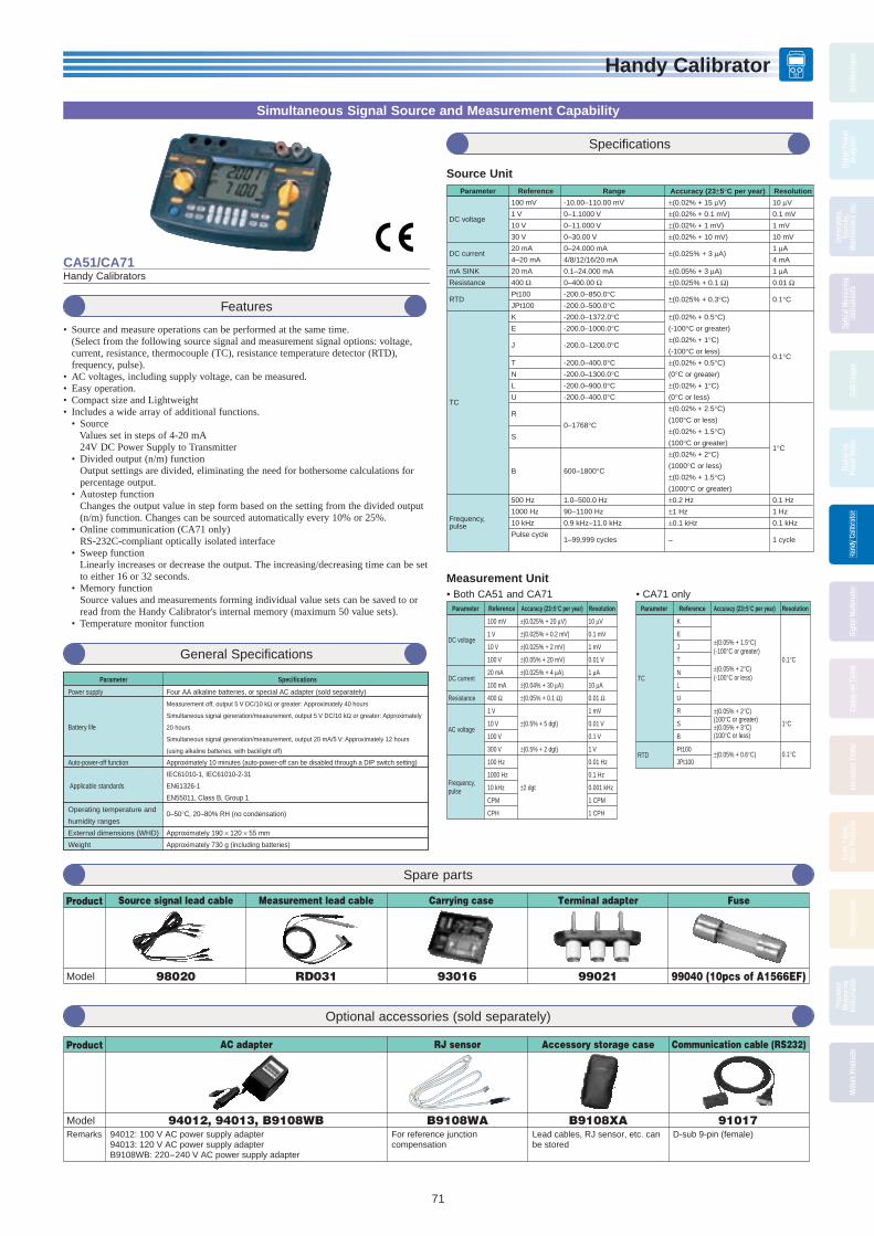
Handy Calibrator
71
Hand
y Ca
libra
tor
Osci
llosc
opes
Digi
tal P
ower
Anal
yzer
s
Gene
rato
rs,
Sour
ces,
Man
omet
ers
etc.
Optic
al M
easu
ring
Inst
rum
ents
Data
Log
ger
Clam
p-on
Pow
er M
eter
Hand
y Ca
libra
tor
Hand
y Ca
libra
tor
Hand
y Ca
libra
tor
Digi
tal M
ultim
eter
Clam
p-on
Tes
ter
Insu
latio
n Te
ster
Eart
h Te
ster
,Ot
her P
rodu
cts
Ther
mom
eter
Prec
isio
nM
easu
ring
Inst
rum
ents
Met
ers
Prod
ucts
Features
• Source and measure operations can be performed at the same time. (Select from the following source signal and measurement signal options: voltage,
current, resistance, thermocouple (TC), resistance temperature detector (RTD), frequency, pulse).
• AC voltages, including supply voltage, can be measured. • Easy operation.• Compact size and Lightweight• Includes a wide array of additional functions. • Source Values set in steps of 4-20 mA 24V DC Power Supply to Transmitter • Divided output (n/m) function Output settings are divided, eliminating the need for bothersome calculations for
percentage output. • Autostep function Changes the output value in step form based on the setting from the divided output
(n/m) function. Changes can be sourced automatically every 10% or 25%. • Online communication (CA71 only) RS-232C-compliant optically isolated interface • Sweep function Linearly increases or decrease the output. The increasing/decreasing time can be set
to either 16 or 32 seconds. • Memory function Source values and measurements forming individual value sets can be saved to or
read from the Handy Calibrator's internal memory (maximum 50 value sets). • Temperature monitor function
Simultaneous Signal Source and Measurement Capability
Specifi cations
General Specifi cations
CA51/CA71Handy Calibrators
Parameter
Power supply
Battery life
Auto-power-off function
Applicable standards
Operating temperature and
humidity ranges
External dimensions (WHD)
Weight
Specifications
Four AA alkaline batteries, or special AC adapter (sold separately)
Measurement off, output 5 V DC/10 kΩ or greater: Approximately 40 hours
Simultaneous signal generation/measurement, output 5 V DC/10 kΩ or greater: Approximately
20 hours
Simultaneous signal generation/measurement, output 20 mA/5 V: Approximately 12 hours
(using alkaline batteries, with backlight off)
Approximately 10 minutes (auto-power-off can be disabled through a DIP switch setting)
IEC61010-1, IEC61010-2-31
EN61326-1
EN55011, Class B, Group 1
0–50°C, 20–80% RH (no condensation)
Approximately 190 × 120 × 55 mm
Approximately 730 g (including batteries)
Parameter
DC voltage
DC current
mA SINK
Resistance
RTD
TC
Frequency,pulse
Reference
100 mV
1 V
10 V
30 V
20 mA
4–20 mA
20 mA
400 Ω
Pt100
JPt100
K
E
J
T
N
L
U
R
S
B
500 Hz
1000 Hz
10 kHz
Pulse cycle
Range
-10.00–110.00 mV
0–1.1000 V
0–11.000 V
0–30.00 V
0–24.000 mA
4/8/12/16/20 mA
0.1–24.000 mA
0–400.00 Ω
-200.0–850.0°C
-200.0–500.0°C
-200.0–1372.0°C
-200.0–1000.0°C
-200.0–1200.0°C
-200.0–400.0°C
-200.0–1300.0°C
-200.0–900.0°C
-200.0–400.0°C
0–1768°C
600–1800°C
1.0–500.0 Hz
90–1100 Hz
0.9 kHz–11.0 kHz
1–99,999 cycles
Resolution
10 µV
0.1 mV
1 mV
10 mV
1 µA
4 mA
1 µA
0.01 Ω
0.1°C
0.1°C
1°C
0.1 Hz
1 Hz
0.1 kHz
1 cycle
Accuracy (23±5°C per year)
±(0.02% + 15 µV)
±(0.02% + 0.1 mV)
±(0.02% + 1 mV)
±(0.02% + 10 mV)
±(0.025% + 3 µA)
±(0.05% + 3 µA)
±(0.025% + 0.1 Ω)
±(0.025% + 0.3°C)
±(0.02% + 0.5°C)
(-100°C or greater)
±(0.02% + 1°C)
(-100°C or less)
±(0.02% + 0.5°C)
(0°C or greater)
±(0.02% + 1°C)
(0°C or less)
±(0.02% + 2.5°C)
(100°C or less)
±(0.02% + 1.5°C)
(100°C or greater)
±(0.02% + 2°C)
(1000°C or less)
±(0.02% + 1.5°C)
(1000°C or greater)
±0.2 Hz
±1 Hz
±0.1 kHz
–
Source Unit
Measurement Unit
Parameter
TC
RTD
Reference
K
E
J
T
N
L
U
R
S
B
Pt100
JPt100
Resolution
0.1°C
1°C
0.1°C
Accuracy (23±5°C per year)
±(0.05% + 1.5°C)(-100°C or greater)
±(0.05% + 2°C)(-100°C or less)
±(0.05% + 2°C)(100°C or greater)±(0.05% + 3°C)(100°C or less)
±(0.05% + 0.6°C)
Parameter
DC voltage
DC current
Resistance
AC voltage
Frequency, pulse
Reference
100 mV
1 V
10 V
100 V
20 mA
100 mA
400 Ω
1 V
10 V
100 V
300 V
100 Hz
1000 Hz
10 kHz
CPM
CPH
Accuracy (23±5°C per year)
±(0.025% + 20 µV)
±(0.025% + 0.2 mV)
±(0.025% + 2 mV)
±(0.05% + 20 mV)
±(0.025% + 4 µA)
±(0.04% + 30 µA)
±(0.05% + 0.1 Ω)
±(0.5% + 5 dgt)
±(0.5% + 2 dgt)
±2 dgt
Resolution
10 µV
0.1 mV
1 mV
0.01 V
1 µA
10 µA
0.01 Ω
1 mV
0.01 V
0.1 V
1 V
0.01 Hz
0.1 Hz
0.001 kHz
1 CPM
1 CPH
• Both CA51 and CA71 • CA71 only
Spare parts
Optional accessories (sold separately)
Product
Model 98020
Source signal lead cable
RD031
Measurement lead cable Carrying case
99021
Terminal adapter
99040 (10pcs of A1566EF)
Fuse
93016
Product
ModelRemarks
94012, 94013, B9108WB94012: 100 V AC power supply adapter94013: 120 V AC power supply adapterB9108WB: 220-240 V AC power supply adapter
AC adapter
B9108WAFor reference junction compensation
RJ sensor
B9108XALead cables, RJ sensor, etc. can be stored
Accessory storage case
91017D-sub 9-pin (female)
Communication cable (RS232)
BOOK_YMI130-EN 71 13.5.9, 10:55:53 AM

Handy Calibrator
72
Hand
y Ca
libra
tor
Osci
llosc
opes
Digi
tal P
ower
Anal
yzer
sGe
nera
tors
,So
urce
s,M
anom
eter
s et
c.
Optic
al M
easu
ring
Inst
rum
ents
Data
Log
ger
Clam
p-on
Pow
er M
eter
Hand
y Ca
libra
tor
Hand
y Ca
libra
tor
Hand
y Ca
libra
tor
Digi
tal M
ultim
eter
Clam
p-on
Tes
ter
Insu
latio
n Te
ster
Eart
h Te
ster
,Ot
her P
rodu
cts
Ther
mom
eter
Prec
isio
nM
easu
ring
Inst
rum
ents
Met
ers
Prod
ucts
CA11EVoltage/Current Calibrator
Source and Measuring of Voltage and Current
CA12ETemperature Calibrator
Simulator of Common Thermocouples and RTD Sensors
Specifi cations
Features
• Source and Measuring of Voltage and Current Generates and measures voltages up to 30 V DC and currents up to 24 mA DC. • Improved display resolution for current The generation /measurement resolution has improved to 0.001 mA.• 24 V (20 mA)/Loop check function*• Enables measurement of generated current signals while supplying loop
power to two-wire transmitter. * Load current: Max. DC22 mA• 20 mA SINK Function Absorbs the voltage supplied from an external power supply to its H terminal and
simulates a two-wire transmitter making it ideal for loop checks. • 4-20 mA and 1-5 V DC Step-up/ down Function• Sweep Function
30 V
10 V
1 V
100 mV
20 mA *1
0 to ±30.00 V DC
0 to ±11.000 V DC
0 to ±1100.0 mV
0 to ±110.00 mV DC
0 to ±24.000 mA DC
0.05% + 2 digits
0.05% + 2 digits
0.05% + 2 digits
0.05% + 7 digits
0.05% + 4 digit
10 mV
1 mV
0.1 mV
0.01 mV
0.001 mA
Input impedance: Approx. 1 MΩ
Input impedance: Approx. 45 Ω
Measurement Functions Accuracy = ±(% of reading + value in the least significant digit), at 23 ±5°C for one year
Range Selection Indication Accuracy Resolution Remarks
Source Functions Accuracy = ±(% of setting + value in mV, µV, or µA), at 23 ±5°C for one year
Range Selection Range of Generated Signal Accuracy Setting Resolution Remarks
Temperature effect: 1/10 of accuracy/°C; however, for 100-mV range, 0.005% + 10 µV/°C *1 The display resolution can select 24.000 or 24.00 displays with dip switch.
*1 The display resolution can select 24.000 or 24.00 displays with dip switch.
30 V10 V1-5 V1 V100 mV20 mA *1
4-20 mA *1
24 V (20 mA) *1
20 mA SINK *1
0 to 30.00 V0 to 11.000 V1/2/3/4/5 V0 to 1.1000 V0.00 to 110.00 mV0 to 24.000 mA4/8/12/16/20 mA24 V0.1 to 24.000 mA
0.05% + 20 mV0.05% + 2 mV0.05% + 2 mV *2
0.05% + 0.2 mV *2
0.05% + 50 µV
0.05% + 4 µA
±10%0.1% + 4 µA
Maximum current: 1 mAMaximum output current: 10 mA
*2 When the load is 1 kΩ or geater, and the error of the lead cables is excluded
Maximum load: 12 V
Maximum curret: 22 mAExtemal power supply: 5 to 28 V
10 mV1 mV1 V step0.1 mV10 µV1 µA4 mA step—1 µA
Features
• Simulator of Common Thermocouples and RTD Sensors Outputs a signal equivalent to signals of ten types of thermocouple K, E, J, T, N, S, B, L,
U and R as well as Pt100 resistance temperature detector. Suitable for a broad range of applications such as maintenance of industrial process
instruments and various thermometers. • Multi-range Thermometer Can be used as a multi-range thermometer. Three-wire RTD connection for an RTD is
possible. • Built-in Sensor for Reference Junction Compensation Reference junction compensation when generating a thermocouple signal can be
performed by the built-in temperature sensor. For more precise compensation, use the external RJC sensor (model B9108WA, sold separately).
Specifi cations
100 mV RTD PT100 *2 *3
(JPT100) 400 Ω
KEJTNRS
B
LU
TC *1*4
–200.0 to 1372.0°C–200.0 to 1000.0°C–200.0 to 1200.0°C–200.0 to 400.0°C–200.0 to 1300.0°C
0 to 1768°C
600 to 1800°C
–200 to 900°C–200 to 400°C0 to ±110.00 mV–200.0 to 850.0°C(–200.0 to 500.0°C)0 to 400.0 Ω
0.05% + 1°C (>-100°C)0.05% + 2°C (≤-100°C)
0.05% + 3°C (<100°C)0.05% + 2°C (≥100°C)0.05% + 4°C (<1000°C)0.05% + 3°C (≥1000°C)0.05% + 0.5°C (<0°C)0.05% + 1°C (≥0°C)0.05% + 30 µV
0.05% + 0.6°C *6
0.05% + 0.2 Ω *6
0.07% + 1.5°C (>-100°C)0.07% + 2°C (≤-100°C)
0.07% + 3°C (<100°C)0.07% + 2°C (≥100°C)0.07% + 4°C (<1000°C)0.07% + 3°C (≥1000°C)0.07% + 1.5°C (<0°C)0.07% + 2°C (≥0°C)0.05% + 30 µV
0.05% + 0.6°C *7
0.05% + 0.2 Ω *7
0.1°C
1°C
0.1°C
10 µV
0.1°C
0.1 Ω
Source and Measurement Functions Accuracy = ±(% of setting or reading + value in °C), at 23 ±5°C for one year
Range Selection Range of Generated Signal/IndicationAccuracy
Source *4 Measurement *5Resolution
Temperature effect: 1/10 of accuracy/°C*1*2*3*4
The accuracy for measurement of thermocouple signals indicates the error againstthe reference EMF table and includes the error of the internal reference junctioncompensation when the temperature at the terminals is stable. External excitation current: 0.5 to 2 mA; add 0.05% + 1°C (or 0.4 Ω)when it is 0.1 mA. Input capacitance of receiver instrument: 0.1 µF or less.When measuring a temperature using a three-wire RTD.
*5
*6
*7
Based on the reference thermal EMF table of JIS C1602-1995Based on the reference resistance table of JIS C1604-1997. Based on the international temperature standard 1990 (ITS-90). The accuracy for generation of thermocouple signals does not include the error of the reference junction compensation. When compensating the output using an RJC sensor, add the accuracy of the RJC sensor. The output compensation is performed every 4 seconds. RJC sensor specifications - measurement range: --10 to 50°C; accuracy (in combination with the CA12E): ±0.5°C at 18 to 28°C and ±1°C at other temperatures.
BOOK_YMI130-EN 72 13.5.9, 10:55:57 AM

Handy Calibrator
Hand
y Ca
libra
tor
Osci
llosc
opes
Digi
tal P
ower
Anal
yzer
s
Gene
rato
rs,
Sour
ces,
Man
omet
ers
etc.
Optic
al M
easu
ring
Inst
rum
ents
Data
Log
ger
Clam
p-on
Pow
er M
eter
Hand
y Ca
libra
tor
Hand
y Ca
libra
tor
Hand
y Ca
libra
tor
Digi
tal M
ultim
eter
Clam
p-on
Tes
ter
Insu
latio
n Te
ster
Eart
h Te
ster
,Ot
her P
rodu
cts
Ther
mom
eter
Prec
isio
nM
easu
ring
Inst
rum
ents
Met
ers
Prod
ucts
73
Features
• Loop check functions • Simultaneous 24 V loop power and mA measurement • HART/BRAIN mode setting with loop power (Adds 250 ohm resistance internally)• Generation functions • SIMULATE (SINK) function simulates transmitters • 4-20 mA span/step/auto-step/sweep output• Measurement functions • High accuracy signal measurement:DC mA 0.05%/30.000 mA • Handheld DMM function • Peak Hold function for the peak voltage measurement of DCS power
supply • Dedicated sensor modes for direct reading of many sensor signal types• Enhanced Safety—helps eliminate electric shocks • Current terminal shutter prevents incorrect connections • 1 A or more of AC/DC current can be read directly using the optional
clamp probe and scaling in SENSOR mode.*1 • Measurement categories 600 V CAT. IV, 1000 V CAT. III *1: AC/DC 600 mV range only
Loop Power and 4 to 20 mA Output function in a DMM
CA450Process Multi Meter
Specifi cations
General Specifi cations
Specifi caton• Display : 5-digit (7 Segment) Measurement DC current 33000, Frequency 19999, Other 6600 Output DC current 25000• Operating temperature and humidity: -20 to 55°C (80%RH or less) with no
condensation• Storage temperature and humidity: -40 to 70 (70%RH or less) with no
condensation • Battery life: DC voltage measurment: Appox.140hours DC current output (SIMULATE) Approx.140hours DC current output (SOURCE) 12mA (500Ω load) Approx.10hours• External dimensions: Approx. 90 (W) × 192 (H) × 49 (D) mm• Weight: Approx. 600g (including the batteries)• Compliant standards:• Safety standards: EN61010-1 and EN61010-031
Measurement Categories:1000 V CATIII, 600 V CATIVFor current measurement and output: 48 V max, 100 mA max CAT ILead cables (98064): 70 VDC, 100 mA CAT IPollution degree 2, indoor useVibration: Sweep vibration frequencies 10 Hz to 5 Hz to 10 Hz Amplitude 0.15 mm (peak value)Duration 30 minutesShock: 1 m drop test as defi ned by the safety standardsAltitude: 2000 m or lessEMC standards: EN61326-1 Class B, EN61326-2-2 EN55011 Class B Group 1Infl uence of radiated immunity: In RF electromagnetic fi elds of 3 V/mEN61326-1 AC voltage measurement, 600 mV range:1.5% of rangeDC voltage measurement, 600 mV range:1% of rangeDC current measurement, all ranges: 1.5% of rangeDC current output: 1.5% of rangeEN61326-2-2 AC voltage measurement (6 V range or higher): Within 5 times the accuracyDC voltage measurement (6 V range or higher): Within 5 times the accuracy
MeasurementFunction Range Resolution Max Accuracy
DCV600 mV/6 V/60 V/600 V/1000 V
0.1 mV/0.001 V/0.01 V/0.1 V/1 V 0.09%+2 digits
ACV 0.1 mV/0.001 V/0.01 V/0.1 V/1 V 0.5%+5 digits
DCA 30 mA/60 mA 0.001 mA/0.01 mA 0.05%+2 digits
Ohm600 Ω/6 kΩ/60 kΩ/600 kΩ/6 MΩ/60 MΩ
0.1 Ω/0.001 kΩ/0.01 kΩ/0.1 kΩ0.001 MΩ/0.01 MΩ
0.2%+2 digits
10Hz to 199.99 Hz, 0.01 Hz
0.005%+1 digitsFreq 90Hz to 1999.9 Hz 0.1 Hz
0.900 kHz to 19.999 kHz 0.001 kHz
Source
DCmA 20 mA 0.001 mA 0.05% of range
Loop Power 24 V24 VDC (typ.)
Load current 20 mA
Other Functions and SpectionFunctions Diode check, Continutity check, Data Hold, Peak Hold, Step mode, linear mode, Sesor mode, MIN/MAX, REL∆%
Accessories
Test leadsModel:98073
Lead CablesModel:98064
FuseModel:99042
DMM Communication Package92015 (*1)
AlligatorTest leads
Model:99014
AC/DCClamp-on Probe
Model:96095
CurrentClamp-on Probe
Model:96001Carrying CaseModel:93029
Magnet hookModel:99032
The Magnet hook can be attached to magnetic body (e.g. iron).
The inner case with detachable straps can be hung on bar.
Carrying CaseModel:93043-P1
(*1) Settings for output is not capable.
BOOK_YMI130-EN 73 13.5.9, 10:55:59 AM
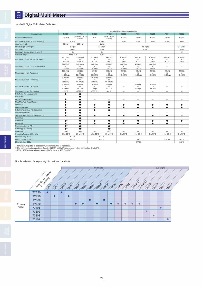
Digital Multi Meter
74
Digi
tal M
ultim
eter
Osci
llosc
opes
Digi
tal P
ower
Anal
yzer
sGe
nera
tors
,So
urce
s,M
anom
eter
s et
c.
Optic
al M
easu
ring
Inst
rum
ents
Data
Log
ger
Clam
p-on
Pow
er M
eter
Hand
y Ca
libra
tor
Digi
tal M
ultim
eter
Digi
tal M
ultim
eter
Digi
tal M
ultim
eter
Clam
p-on
Tes
ter
Insu
latio
n Te
ster
Eart
h Te
ster
,Ot
her P
rodu
cts
Ther
mom
eter
Prec
isio
nM
easu
ring
Inst
rum
ents
Met
ers
Prod
ucts
7533
serie
s
7534
serie
s
3.5 Digits4.5 Digits
TY720TY710TY530TY52073201732027320373101
Existingmodel
Discon
tinue
d pr
oduc
ts
for r
eplac
ing
7340
1
7536
03
7532
01
7532
02
7532
03
7537
01
7537
02
7537
03
7537
04
7538
01
7330
3
7330
2
7330
1
7544
01
7544
02
7340
2
Handheld Digital Multi Meter Sellection
Simple selection for replacing discontinued products
Handhel Digital Multi Meter Models
Function item TY710 TY720 TY520 TY530 73201 73202 73203 73204 73101
Measurment Function Ture RMSTure RMS MEAN
SellectRMS
RMS MEAN Sellect
MEAN MEAN MEAN MEAN MEAN
Max. Measurrement Accuracy at DCV 0.02% 0.09% 0.5% 0.5% 0.3% 0.5% 0.7%
Wide bandwidth 20KHz 100KHz 1kHz — —
Display Digits(Uint:Digit) 5 digits 3.5 Digits 3.5 Digits 3.5 Digits
Max. Value 50000 6000 4300 4300
Bar Graph Dsiplay (Uints:Segment) 51 31 — 32
LCD Back Light White LED LED — —
Max.Measurement Voltage (AC/or DC)50.000mV
to1000.0V
50.000mV to
1000.0V
600.0mV to
1000V
600.0mV to
1000V
4.000V*3
to600V
4.000V*3
to600V
4.000V*3
to600V
4.000V*3
to600V
4.000V*3
to600V
Max.Measurement Currents (AC/or DC)500.00µA
to 10.000A
500.00µAto
10.000A
600.0µAto
10.00A
600.0µAto
10.00A
400.0µAto
10.00A
400.0µAto
10.00A
400.0µAto
10.00A— —
Max.Measurement Resistance500.00Ω
to50.000MΩ
500.00Ωto
50.000MΩ
600.0Ω to
60.00MΩ
600.0Ω to
60.00MΩ
400.0Ωto
40.00MΩ
400.0Ωto
40.00MΩ
400.0Ωto
40.00MΩ
400.0Ωto
40.00MΩ
400.0Ωto
40.00MΩ
Max.Measurement Frequency2.000Hz
to99.99kHz
2.000Hzto
99.99kHz
10.00Hzto
99.99kHz
10.00Hzto
99.99kHz— — — — —
Max.Measurement Capcitance5.000nF
to 50.00mF
5.000nF to
50.00mF
10.00nFto
1000µF
10.00nFto
1000µF—
20.00nF to
200.0µF
20.00nF to
200.0µF— —
Max.Measurement Temperature +1372°C*1 +1372°C*1 +600°C*1 +600°C*1 — — — — —
Duty Ratio (%) Measuement — — — — — — —
Low-Power — — — — — — — —
AC+DC Measurement — — — — — — —
Max./Min./Ave. Value Memory — — — — — —
Diode Test
Continuity Check
Relative/Percentage (%) calculation — — — — —
Decibel calculation — — — — — —
Selection Auto range or Manual range —
Peak Hold — — — — — — — —
Data Hold *2
Auto Hold
Communication for PC *2 *2 — *2 — — — — —
Data Logging Memory *2 *2 — *2 — — — — —
Data Memory 1000 10000 — 1600 — — — — —
Operating Temp. and Humidity -20 to 55°C -20 to 55°C -10 to 55°C -10 to 55°C 0 to 50°C 0 to 50°C 0 to 50°C 0 to 50°C 0 to 50°C
Electric Safety 1000V CAT III CAT III — —
Electric Safety 600V CAT IV CAT IV CAT II CAT III CAT III
Electric Safety 300V — — CAT III — CAT II
*1 Temperature probe is necessary when measuring temperature.*2 The communications package (model: 92015) for DMM is necessary when connecting it with PC. *3 73101,732Series minimum range of DCvoltage is 400. 0 mVDC.
BOOK_YMI130-EN 74 13.5.9, 10:56:15 AM

Digital Multi Meter
75
Digi
tal M
ultim
eter
Osci
llosc
opes
Digi
tal P
ower
Anal
yzer
s
Gene
rato
rs,
Sour
ces,
Man
omet
ers
etc.
Optic
al M
easu
ring
Inst
rum
ents
Data
Log
ger
Clam
p-on
Pow
er M
eter
Hand
y Ca
libra
tor
Digi
tal M
ultim
eter
Digi
tal M
ultim
eter
Digi
tal M
ultim
eter
Clam
p-on
Tes
ter
Insu
latio
n Te
ster
Eart
h Te
ster
,Ot
her P
rodu
cts
Ther
mom
eter
Prec
isio
nM
easu
ring
Inst
rum
ents
Met
ers
Prod
ucts
A New De Facto Standard for Handheld DMM
TY700 SeriesDigital Multimeters
• Maximum Measurement Accuracy: 0.020% rdg + 2 dgt • Highly Reliable: Closed case calibration• Full Support of Data Management: Measured data stored in internal memory• Safe Design: Shutters prevent erroneous insertion of test leads into current measurement-
terminals (terminal shutters)• Shockproof elastomer casing
• Wide operating temperature range: -20 °C to 55°C
General Specifi cationsAdditional Functions USB communication (optional adapter & software),
data memory (TY720: 10,000 data, TY710: 1,000 data), max/min value memory, relative/percentage value computation, logarithm computation, data/auto hold, peak hold (TY720), overvoltage warning, backlight
Power Supply Four AA (R6) dry cellsBattery Life Approx. 120 hoursDimensions 90 (W) × 192 (H) × 49 (D) mmWeight Approximately 560 g (including batteries)Safety Standards 1000 V CAT. 3, 600 V CAT. 4
Features• Data saved in the internal memory PC transfer is possible (Save memories or Logging Memories)• DMM measurements show in real time monitor display is possible.• Large amounts of data not covered by the internal memory PC communication with data transfer is possible. At the same time Excel transferable is also. Maximum incoming data: 32767 • Measurement data to Excel direct deployment is possible. Automatically creates a chart sheet.
DMM of dedicated application software (Model: 92015 )DMM’s and you can easily manage the data in memory. Is also capable of real-time communications
92015 product specifi cation:Communication cable
Communications cable: infrared communication adapter + communications cable (USB specifi -cations) 2 m length
Interface standards: USB specifi cation conforms to the 1.1 Available models : TY710 , TY720 , TY530
Application softwareOperating environment of the personal computerOS: Windows XP / Vista / 7 CPU: Pentium 133 MHz or higherMemory: 64 MB Hard disk has free space or more storage: 10 MB Over, CD drive Excel: since the Excel2000 Software: CD, communication cable (including adapter),
User’s manual
TY710 TY720Detection RMS Switching detection (RMS or MEAN)Item Range Accuracy
DCV
50mV 0.05+10500mV/2400mV 0.02+25V 0.025+550V/500V/1000V 0.03+2
ACV[RMS]
Upper: 10 to 20HzLower: 20Hz to 1kHz
Upper: 1kHz to 10kHzLower: 10kHz to 20kHz
Upper: 20kHz to 50kHzLower: 50kHz to 100kHz
Upper: 10 to 20HzLower: 20Hz to 1kHz
Upper: 1kHz to 10kHzLower: 10kHz to 20kHz
Upper: 20kHz to 50kHzLower: 50kHz to 100kHz
50mV——
——
——
2+800.4+40
5+405.5+40
15+4015+40
50mV/5V/50V/500V 1.5+30
0.7+30
0.7+302+50
—— 1+30
0.4+30
0.4+301+40
2+705+200
1000V3+30—
——
3+30—
——
ACV[MEAN]
10 to 20Hz 20Hz to 500Hz 500Hz to 1kHz50mV — 4+80 1.5+30 5+3050mV/5V/50V/500V/1000V
— 2+30 1+30 3+30
DCV+ACV
Upper: DC,10 to 20HzLower: DC,20Hz to 1kHz
Upper: DC,1kHz to 10kHzLower: DC,10kHz to 20kHz
Upper: DC,20kHz to 50kHzLower: DC,50kHz to 100kHz
Upper: DC,10 to 20HzLower: DC,20Hz to 1kHz
Upper: DC,1kHz to 10kHzLower: DC,10kHz to 20kHz
Upper: DC,20kHz to 50kHzLower: DC,50kHz to 100kHz
5V/50V/500V1.5+101+10
1+102+10
——
1.5+100.5+10
0.5+101+10
2+105+20
1000V1.5+101+10
——
——
1.5+100.5+10
——
——
DCA
500µA/5000µA/50mA/500mA
0.2+5
5A 0.6+1010A 0.6+5
ACA[RMS]
10Hz to 20Hz 20Hz to 1kHz 1kHz to 5kHz 10Hz to 20Hz 20Hz to 1kHz 1kHz to 5kHz500µA/5000µA/50mA/500mA 1.5+20 1+20 —
1+20 0.75+20 1+30
5A/10A 1.5+20 1+20 2+30
ACA[MEAN]
10Hz to 20Hz 20Hz to 1kHz 1kHz to 5kHz500µA/5000µA/50mA/500mA
— 2+20 1.5+20 2+30
5A/10A — 3+20 2+20 4+30
DCA+ACA
DC,10 to 20Hz DC,20Hz to 1kHz DC,1kHz to 5kHz DC,10 to 20Hz DC,20Hz to 1kHz DC,1kHz to 5kHz500µA/5000µA/50mA/500mA 2+10 1.5+10 —
1.5+10 1+10 1.5+10
5A/10A 2+10 1.5+10 3+10
Resistance
500Ω/5kΩ/50kΩ500kΩ 0.1+2 0.05+2
5MΩ 0.5+250MΩ 1+2
Low-powerResistance
5kΩ/50kΩ/500kΩ — 0.2+35MΩ — 1+3
Frequency 2.0Hz to 99.99kHz 0.02+1
Capacitance
5nF/50nF/500nF5µF/50µF
1+5
500µF 2+55mF/50mF 3+5
Continuity check 550Ω Buzzer sounds at 100±50Ω or lessDiode test 2.4V 1+2Temperature -200 to 1372°C 1+1.5°C
BOOK_YMI130-EN 75 13.5.9, 10:56:20 AM

Digital Multi Meter
76
Digi
tal M
ultim
eter
Osci
llosc
opes
Digi
tal P
ower
Anal
yzer
sGe
nera
tors
,So
urce
s,M
anom
eter
s et
c.
Optic
al M
easu
ring
Inst
rum
ents
Data
Log
ger
Clam
p-on
Pow
er M
eter
Hand
y Ca
libra
tor
Digi
tal M
ultim
eter
Digi
tal M
ultim
eter
Digi
tal M
ultim
eter
Clam
p-on
Tes
ter
Insu
latio
n Te
ster
Eart
h Te
ster
,Ot
her P
rodu
cts
Ther
mom
eter
Prec
isio
nM
easu
ring
Inst
rum
ents
Met
ers
Prod
ucts
73101Pocket Digital Multimeter
4300 count displayContinuity Check and Diode TestAuto HoldAuto Power Off
73101 Specifi cations
Accuracy: (23°C ±5°C, Less than 80% RH), ±(% rdg + dgt)
Pocket DMM with Superb Portability
732 SeriesDigital Multimeters
3.5 digits (4,300-count), Mean val ue typeMeasurement Functions: Voltage, Current, Resistance, Con-tinuity Check, Diode Test, CapacitanceFeatures: Auto hold, Auto power-off
Low-cost Handheld DMM
Provides Safety Levels Demanded in Field Work
Model 73201 73202 73203 73204
Detection Mean value
Item Range Accuracy
DCV 400.0 mV/4.000 V/40.00 V/400.0 V/600 V
0.5%+10.75%+1 0.5%+1 0.3%+1 0.5%+1
ACV 4.000 V/40.00 V/400.0 V/600 V 1.0%+5 0.75%+5
DCA400.0 µA/4000 µA/40.00 mA/400.0 mA/10.00 A
1.0%+22.0%+2 −
ACA(40 to 500 Hz)
400.0 µA/4000 µA/40.00 mA/400.0 mA/10.00 A
2.0%+202.0%+52.0%+202.0%+52.0%+20
−
Resistance400.0 Ω/4.000 kΩ/40.00 kΩ/400.0 kΩ/4.000 MΩ/40.00 MΩ
0.75%+20.75%+12.0%+15.0%+2
Item Range Accuracy Input Resistance
DCV400.0 mV4.000 V
40.00/400.0/600 V
1.2%+20.7%+11.2%+1
>100 MΩ11 MΩ10 MΩ
ACV 4.000 V40.00/400.0/600 V 2.0%+5 10 MΩ
Resistance
400.0 Ω4.000 k/40.00 k/400.0 kΩ
4.000 MΩ40.00 MΩ
1.2%+22.0%+35.0%+3
Continuity check 400.0 Ω −
Diode test 2.00 V 1.5%+1 Open-circuit Voltage<3.4 VTesting Current<1.0 mA
General Specifi cations • External dimensions: 74 (W) × 155 (H) × 31 (D) mm • Weight: Approx. 240 g • Power Supply: Two AAA (LR03 or R03) dry cells
732 Series Specifi cations
Accuracy: (23°C ±5°C, Less than 80% RH), ±(% rdg + dgt)
Genetal Specifi cations • External dimensions: 76 (W) × 117 (H) × 18 (D) mm • Weight : Approx. 110 g • Power Supply: Two LR-44 dry cells
TY500 SeriesDigital Multimeters
3.5 digits (6,000-count, 31-segment bar graph display), RMS typeMeasurement Func tions: Voltage, Cur rent, Re sis tance, Con ti nu ity Check, Diode Test, Frequency, Ca pac i tance, TemperatureFeatures: Closed case calibration, Hi-impact overmold case, USB communication (optional adapter & software) (TY530 only), data memory (1,600 data for TY530 only)Safety Standards: 1000 V CAT. 3, 600 V CAT. 4
General Specifi cations • External dimensions: 90 (W) × 192 (H) × 49 (D) mm • Weight : Approx. 570 g • Power Supply: Four AA (R6) dry cells
TY500 Series Specifi cations
Accuracy: (23°C ±5°C, Less than 80% RH), ±(% rdg + dgt)
TY520 TY530
Detection RMS Switching detection (RMS or MEAN)
Item Range Accuracy
DCV600mV/6V/60V/600V 0.09 + 2
1000V 0.15 + 2
ACV
50/60Hz 40 to 500Hz 500Hz to 1kHz
600mV/6V/60V/600V1000V 0.5 + 5 1 + 5
1.5 + 5
—
DCA600µA/6000µA/60mA 0.2 + 2
600mA/6A/10A 0.5 + 5
ACA50/60Hz 40Hz to 1kHz
600µA/6000µA/60mA/600mA/6A/10A 0.75 + 5 1.5 + 5
Resistance
600Ω/6kΩ/60kΩ/600kΩ 0.4 + 1
6MΩ 0.5 + 1
60MΩ 1 + 2 (0 to 40MΩ)2 + 2 (40 to 60MΩ)
Frequency 10.0Hz to 99.99kHz 0.02 + 1
Capacitance
10nF 2 + 10
100nF/1µF/10µF 2 + 5
100µF/1000µF 3 + 5
Continuity check 600Ω Buzzer sounds at 50±30Ω or less
Diode test 2V 1 + 2
Temperature -50 to 600°C 2 + 2°C
BOOK_YMI130-EN 76 13.5.9, 10:56:23 AM

Digital Multi Meter
77
Digi
tal M
ultim
eter
Osci
llosc
opes
Digi
tal P
ower
Anal
yzer
s
Gene
rato
rs,
Sour
ces,
Man
omet
ers
etc.
Optic
al M
easu
ring
Inst
rum
ents
Data
Log
ger
Clam
p-on
Pow
er M
eter
Hand
y Ca
libra
tor
Digi
tal M
ultim
eter
Digi
tal M
ultim
eter
Digi
tal M
ultim
eter
Clam
p-on
Tes
ter
Insu
latio
n Te
ster
Eart
h Te
ster
,Ot
her P
rodu
cts
Ther
mom
eter
Prec
isio
nM
easu
ring
Inst
rum
ents
Met
ers
Prod
ucts
93029
RD031
323
110 50 10
1200 50
3.2
22 14
90050200
50 10
1200
1.6
22
14
150
273
110
90051 50
26
14
30 110
178
6
50 10
1200
15
6.0 14
90055 50
13.5
177.5
30 110 50 1025.5
5.5
1200
15
6.0 14
90056
96095
9807392015
Specifi cations
96095Model
12mm
AC10mV/A(AC 1~1300mVrms)50/60Hz
1.2%+0.4mV
-30 to 70°C relative Humidity 85% or less (no condensation)
Low battery warning :2.2V±0.2V or less red LED flash1.9V±0.2V or less Power off
Approx. 35Hours till a low battery indicator flashes *1
Dimensions&Weight127 (L) × 42 (W) × 22 (D) mmCord length: Approx.1200mm Weight: Approx 140g
EN61010-1:CAT3Pollution degree2, Altitude 2000m or less for indoor useEN61326-1:ClassB,EN61326-2-032
*1 From low battery warning to power off is about 5hours
Conductor Size
Measurement range
AC 0.1 to 130A
DC 0 to ±180A
General specifications
Output voltage Accuracy (at 23°C±5°C)
Operating Temp&Humidity range
Storage Temp&Humidity range
Power sourceDC3V(Size AAA alkaline Battery LR03 × 2pcs)
Continuous use
Applicable standards
Accessories Soft case(94030),Battery,User’s Manual
-10 to 55°C relative Humidity 85% or less (no condensation)
2.5%+0.4mV
40Hz to 1kHz
1.2%+0.4mVDC10mV/A (DC 0~±1800mV)
96095AD/DC Clamp-on Probe
• Light and compact, easy to carry and easy to clamp on crowded wirings.
• Expands measuring span of currents and assure safety when measuring with any kind of DMM.
96001
Standerd Accessories
Applicable DMM Models
TY700 TY500 732
Name Model Specifi cation TY710 TY720 TY520 TY530 01 02 03 04
Communication Package forDigital Multimeters 92015 Communication Adapter for USB+cable+Application Software
Printer Adapter and Cable 97016 Printer Adapter and Cable
Printer 97010 Thermal printer(paper windth:112mm)
AC adpter 94006 For Europe 230VAC±10%
94007 For USA 120VAC±10%
Thermal printer paper 97080 1 Package of 10 rolls
Test leads with Alligator Clip 99014 1000V CAT# 600V CAT$Red/Black(1set)
Alligator Clips B9646HF Red/Black(1set)
Rubber Case 93007
Carrying Case 93029 Hard case
B9646GB Hard case
Temperature Probe (Thermocouple type K)(Banana plag output)
90050 -50 to 150°C for liquld
90051 -50 to 600°C for liquld
90055 -20 to 250°C for surface
90056 -20 to 500°C for surface
Currents Clamp-on probe 96001 For 400AAC Output:AC10mV/A*1
96095 For 130AAC/180ADCOutput: AC10mV/A or DC10mV/A*2
Applicable DMM Models
TY700 TY500 732
Name Model Specifi cation TY710 TY720 TY520 TY530 01 02 03 04
Test leads 98073 1000V CAT# 600V CAT $ Red/Black(1set)
RD031 L-plug,Red/Black(1set)
Fuse 99015 440mA/1000V
99016 10A/1000V
F02 15A/250V
F05 500mA/250V
Accessorise
*1 Please use it with the ACV range. It is necessary to read the indicated value in a different way as TY710 and the TY720,732 series. The example: In AC1V display = 100A TY520 and TY530, it is possible to scale it. (Even 60A or less display is possible in case of 96001. )*2 Please use it with ACV or DCV range. It is necessary to read the indicated value in a different way as TY710 and the TY720,732 series. The example: In AC1V display = 100A TY520 and TY530, it is possible to scale it. (Even 60A or less display is possible in case of 96095. )
DMM Accessories
BOOK_YMI130-EN 77 13.5.9, 10:56:27 AM

Clamp-on Tester
78
Clam
p-on
Tes
ter
Osci
llosc
opes
Digi
tal P
ower
Anal
yzer
sGe
nera
tors
,So
urce
s,M
anom
eter
s et
c.
Optic
al M
easu
ring
Inst
rum
ents
Data
Log
ger
Clam
p-on
Pow
er M
eter
Hand
y Ca
libra
tor
Digi
tal M
ultim
eter
Clam
p-on
Tes
ter
Clam
p-on
Tes
ter
Clam
p-on
Tes
ter
Insu
latio
n Te
ster
Eart
h Te
ster
,Ot
her P
rodu
cts
Ther
mom
eter
Prec
isio
nM
easu
ring
Inst
rum
ents
Met
ers
Prod
ucts
CL220Clamp-on Tester
• ACA/DCA• φ 24• AC/40 to 300 A• DC/40 to 300 A
AC/DC Current Measurement
CL150/CL155Clamp-on Testers
• ACA• φ 54• AC/400 to 2000 A• AC V/DC V/Ω• DC Output• RMS for CL155
Wide Range of Current Measurement
ACA
ACV
DCVResistance
Item Range
400A
2000 A (0 to 1500 A)
2000 A (1500 to 2000 A)
40/400/750V
40/400/1000V400/4 k/40 k/400 kΩ
1.0 + 3 (50/60 Hz)2.0 + 3 (40 to 1 kHz)1.0 + 3 (50/60 Hz)3.0 + 3 (40 to 1 kHz)3.0 (50/60 Hz)1.0 + 2 (50/60 Hz)1.5 + 3 (40 to 1 kHz)1.0 + 21.5 + 2, Beep sound at less than 50 ±35 Ω
AccuracyAccuracy: (23°C ±5°C, Less than 75% RH), ±(% rdg + dgt)
ACA
DCA
Item Range40A
300 A (±20 to ±200 A)300 A (±200 to ±300 A)
40A
300 A (20 to 200 A)
300 A (200 to 300 A)
1.0 + 41.5 + 43.01.0 + 4 (50/60 Hz)2.5 + 4 (20 to 1 kHz)1.5 + 4 (50/60 Hz)2.5 + 4 (20 to 1 kHz)3.5 (50/60 Hz)4.0 (20 to 1 kHz)
AccuracyAccuracy: (23°C ±5°C, Less than 85% RH), ±(% rdg + dgt)
CL150/CL155 Specifi cations CL220 Specifi cations
CL130/135Clamp-on Testers
• ACA• φ 33• AC/200 to 600 A• AC V/Ω• RMS for CL135
AC/DC Current Measurement
CL120Clamp-on Tester
• ACA• φ 24• AC/20 to 200 A
Light weight & compact design
ACA
Item Range20A
200A
2.0+7 (50 to 1 kHz)2.0+5 (50/60 Hz)3.0+10 (40 to 1 kHz)
AccuracyAccuracy: (23°C ±5°C, Less than 75% RH), ±(% rdg + dgt)
ACA
ACV
Resistance
Item Range
200A
600A
200V/600V
200 Ω
1.5+6 (50/60 Hz)2.0+5 (40 to 1 kHz)1.0+3 (50/60 Hz)2.0+5 (40 to 1 kHz)1.0+2 (50/60 Hz)1.5+4 (40 to 1 kHz)1.2+4, Beeps at below 30 Ω (continuity check)
1.5+4 (50/60 Hz)2.0+5 (40 to 1 kHz)1.5+4 (50/60 Hz)2.0+5 (40 to 1 kHz)1.0+2 (50/60 Hz)1.5+4 (40 to 1 kHz)
Accuracy (CL130/CL135)Accuracy: (23°C ±5°C, Less than 85% RH), ±(% rdg + dgt)
CL120 Specifi cations CL130/CL135 Specifi cations
ModelDiameter of measurable
conductorRange Accuracy
AC
cur
rent
DC
cur
rent
Leak
cur
rent
DC
vol
tage
AC
vol
tage
Res
ista
nce
Con
tinui
ty c
heck
Freq
uenc
y
True
RM
S
Out
put
Dat
a ho
ld
Pea
k ho
ld
Filte
r
CL120 φ24 20 to 200 A 2.0+7
CL130 φ33 200 to 600 A 1.5+6
CL135 φ33 200 to 600 A 1.5+4
CL150 φ54 400 to 2000 A 1.0+3
CL155 φ54 400 to 2000 A 1.0+3
CL220 φ24 400 to 300 A 1.0+4
CL235 φ33 400 to 600 A 1.0+5
CL250 φ55 400 to 2000 A 1.5+2
CL255 φ55 400 to 2000 A 1.5+2
CL320 φ24 20 mA to 200 A 2.0+4
CL340 φ40 40 mA to 400 A 1.0+5
CL345 φ40 40 mA to 400 A 1.0+5
30031A φ40 3 mA to 60 A 1.0+5
30032A φ40 3 mA to 60 A 1.0+5
CL360 φ68 200 mA to 1000 A 1.0+2
CL420 φ6 DC 20 to 100 mA 0.2+3
BOOK_YMI130-EN 78 13.5.9, 11:02:50 AM

Clamp-on Tester
79
Clam
p-on
Tes
ter
Osci
llosc
opes
Digi
tal P
ower
Anal
yzer
s
Gene
rato
rs,
Sour
ces,
Man
omet
ers
etc.
Optic
al M
easu
ring
Inst
rum
ents
Data
Log
ger
Clam
p-on
Pow
er M
eter
Hand
y Ca
libra
tor
Digi
tal M
ultim
eter
Clam
p-on
Tes
ter
Clam
p-on
Tes
ter
Clam
p-on
Tes
ter
Insu
latio
n Te
ster
Eart
h Te
ster
,Ot
her P
rodu
cts
Ther
mom
eter
Prec
isio
nM
easu
ring
Inst
rum
ents
Met
ers
Prod
ucts
Leakage Currents of 1 mA measurement
CL250/CL255Clamp-on Testers
• ACA/DCA• φ 55• AC/400 to 2000A, DC/400 to 2000A• AC V/DC V/Ω• DC Output• Hz,RMS for CL255
Wide Range of ACA/DCA measurement
CL235Clamp-on Tester
• ACA/DCA• φ 33• AC/400 to 600A, DC/400 to 1000A• AC V/DC V/Ω/Hz• RMS
RMS ACA/DCA measurement
ACA
DCA
ACV
DCVResistanceFrequency
Item Range
400/600A
400/1000A
40/400/600V
40/400/600V400/4000Ω
10 to 3000Hz
1.5+5 (50/60Hz)3.5+5 (40 to 1kHz)1.0+51.5+5 (50/60Hz)3.5+5 (40 to 1kHz)1.0+51.0+5, Beeps at below 20Ω (continuity check)1.5+5
AccuracyAccuracy: (23°C ±5°C, Less than 75% RH), ±(% rdg + dgt)
DCA
ACA
Item Range400/2000A
400A/2000A (0 to 1000A)
2000A (1001 to 2000A)
1.5+21.5+2 (50/60Hz)3.0+4 (40 to 500Hz)5.0+4 (500 to 1kHz)3.0+2 (50/60Hz)
AccuracyAccuracy: (23°C ±5°C, Less than 75% RH), ±(% rdg + dgt)
CL235 Specifi cations CL250 Specifi cations
CL320Leakage Clamp-on Tester
• ACA• φ 24• AC/20mA to 200A
Compact design of Leakage current measurement
ACA
Item Range
20mA/200mA200A (0 to 100A)
200A (100.1 to 200A)
2.0+4 (50/60Hz)5.0+6 (40 to 400Hz)5.0+4 (50/60Hz)
3.0+5 (50/60Hz)
5.0+5 (50/60Hz)
Accuracy
WIDE (40 to 400Hz) 50/60Hz
Accuracy: (23°C ±5°C, Less than 85% RH), ±(% rdg + dgt)
CL320 Specifi cations
CL340/CL345Leakage Clamp-on Testers
• ACA• φ 40• AC/40mA to 400A• RMS for CL345
Leakage current measurement
ACA
Item Range
40mA/400mA400A (0 to 350A)400A (350 to 400A)
2.5+10 (20 to 1kHz)2.5+10 (40 to 1kHz)5.0 (40 to 1kHz)
1.0+5 (50/60Hz)1.0+5 (50/60Hz)2.0 (50/60Hz)
Accuracy
WIDE (20Hz) 50/60Hz
Accuracy: (23°C ±5°C, Less than 85% RH), ±(% rdg + dgt)
CL340 Specifi cations
CL360Leakage Clamp-on Tester
• ACA• φ 68• AC/200mA to 1000A• DC/AC Output
Wide Range of Leakage current measurement
ACA
Item Range
20mA/2A/20A
200A
1000A (0 to 500A)
1000A (501 to 1000A)
1.0+2 (50/60Hz)3.0+2 (40 to 1kHz)1.5+2 (50/60Hz)3.5+2 (40 to 1kHz)1.5+2 (50/60Hz)3.5+2 (40 to 1kHz)5.0 (50/60Hz)10.0 (40 to 1kHz)
1.5+2
2.0+2
2.0+2
5.5
Accuracy
WIDE (40 to 1kHz) 50/60Hz
Accuracy: (23°C ±5°C, Less than 85% RH), ±(% rdg + dgt)
CL360 Specifi cations
DCA
ACA
Item Range400/2000A
400A/2000A (150 to 1700A)
2000A (1701 to 2000A)
1.5+21.5+3 (50/60Hz)3.0+4 (30 to 1kHz)3.5+3 (50/60Hz)
AccuracyAccuracy: (23°C ±5°C, Less than 75% RH), ±(% rdg + dgt)
CL255 Specifi cations
ACA
Item Range
40mA/400mA400A (0 to 300A)400A (300 to 400A)
2.5+10 (20 to 1kHz)2.5+10 (40 to 1kHz)5.0 (40 to 1kHz)
1.0+5 (50/60Hz)1.0+5 (50/60Hz)2.0 (50/60Hz)
Accuracy
WIDE (20Hz) 50/60Hz
Accuracy: (23°C ±5°C, Less than 85% RH), ±(% rdg + dgt)
CL345 Specifi cations
30031A/30032ALeakage Clamp-on Tester
• ACA• φ 40• AC/3 mA to 60 A
ACA
Item Range
0 to 30 mA0 to 50 A50 to 60 A
1.0+5 (50±1.0Hz/60±1.0Hz)
5.0+5 (50±1.0Hz/60±1.0Hz)
1.5+5 (50±1.0Hz/60±1.0Hz)
5.5+5 (50±1.0Hz/60±1.0Hz)
Accuracy
30031A, 30032A Filter OFF 30032A Filter ON
Accuracy: (23°C ±5°C, Less than 80% RH), ±(% rdg + dgt)
30031A/30032A Specifi cations
CL420Clamp-on Process Meter
• DCmA• φ 6• DC/20mA to 100mA• DC Output
DC signals of 4 to 20mA measurement
DCmA
Item Range20mA
100mA0.2+51.0+5
AccuracyAccuracy: (23°C ±5°C, Less than 80% RH), ±(% rdg + dgt)
CL420 Specifi cations
BOOK_YMI130-EN 79 13.5.9, 11:02:56 AM

Insulation Tester
80
Insu
latio
n Te
ster
Osci
llosc
opes
Digi
tal P
ower
Anal
yzer
sGe
nera
tors
,So
urce
s,M
anom
eter
s et
c.
Optic
al M
easu
ring
Inst
rum
ents
Data
Log
ger
Clam
p-on
Pow
er M
eter
Hand
y Ca
libra
tor
Digi
tal M
ultim
eter
Clam
p-on
Tes
ter
Insu
latio
n Te
ster
Insu
latio
n Te
ster
Insu
latio
n Te
ster
Eart
h Te
ster
,Ot
her P
rodu
cts
Ther
mom
eter
Prec
isio
nM
easu
ring
Inst
rum
ents
Met
ers
Prod
ucts
Selection Guide
Two choices:Choose an analog model if visual recognition is of utmost importance, or a digital model if precise numeric recognition is of utmost importance.
Type
A wide choice of voltage/resistance ratings, from 25 V/5 MΩ to 1000 V/2000 MΩSome models have two or three ran-ges; thus, you need not take more than one instrument to the site.
Ratings
Each series includes a model or models with a backlight for working in dark places. Multi-functional models capable of, for example, AC voltage meas-urement, are also available.
Functionality
Optional test probes and probe tips are available for a variety of test environments.
Accessories
Points on How to Choose an Insulation Tester
3 1/2-digit
LCD
Automatic discharge
Conductor resistancemeasurement
Comparator function
Memory function
P.81
125V/200MΩ250V/200MΩ500V/2000MΩ1000V/2000MΩ
Automatic discharge
Battery check
Automatic discharge
Battery check
Battery check
P.82
P.82
3213A
*
Dig
ital insu
lation
testersA
nalo
g in
sulatio
n testers
4ranges
2 & 3ranges
Singlerange
Singlerange
Analog
Analog
Analog
MY40
*
2406E
MY10
Type RatingSuffix Code& Backlight
Series/Model
Display Additional Function External View PageAC VoltageMeasuring range
25V/5MΩ
50V/10MΩ
125V/20MΩ
125V/20MΩ
250V/50MΩ
125V/20MΩ
250V/50MΩ
500V/100MΩ
250V/50MΩ
500V/100MΩ
1000V/2000MΩ
250V/500MΩ
500V/1000MΩ
1000V/2000MΩ
125V/20MΩ
250V/50MΩ
500V/100MΩ
500V/1000MΩ
1000V/2000MΩ
100V/20MΩ
250V/50MΩ
500V/100MΩ
500V/1000MΩ
1000V/2000MΩ
31 (N/A)
41 (EL-illuminated)
32 (N/A)
42 (EL-illuminated)
33 (N/A)
43 (EL-illuminated)
34 (N/A)
44 (EL-illuminated)
35 (N/A)
45 (EL-illuminated)
01 (afterglow-illuminated)
02 (afterglow-illuminated)
03 (afterglow-illuminated)
04 (afterglow-illuminated)
05 (afterglow-illuminated)
41 (N/A)
42 (N/A)
43 (N/A)
44 (N/A)
45 (N/A)
01 (EL-illuminated) 0–600V
0–300V
0–300V
0–600V
0–600V
0–600V
0–250V
0–300V
0–500V
0–500V
0–500V
0–150V
0–250V
0–300V
0–300V
0–300V
* JIS mark has changed from 2008
P.82
BOOK_YMI130-EN 80 13.5.9, 11:03:03 AM

Insulation Tester
81
Insu
latio
n Te
ster
Osci
llosc
opes
Digi
tal P
ower
Anal
yzer
s
Gene
rato
rs,
Sour
ces,
Man
omet
ers
etc.
Optic
al M
easu
ring
Inst
rum
ents
Data
Log
ger
Clam
p-on
Pow
er M
eter
Hand
y Ca
libra
tor
Digi
tal M
ultim
eter
Clam
p-on
Tes
ter
Insu
latio
n Te
ster
Insu
latio
n Te
ster
Insu
latio
n Te
ster
Eart
h Te
ster
,Ot
her P
rodu
cts
Ther
mom
eter
Prec
isio
nM
easu
ring
Inst
rum
ents
Met
ers
Prod
ucts
MY40Digital Insulation Tester
Features
• Multifunction Insulation resistance, AC voltage and conductor resistance measurement Insulation test mode: Comparator, memory, auto-hold and discharge functions All test modes: Live-line alarm (excluding AC voltage measurement), battery
check and automatic power-off• Easy-to-view, fl uctuation-free display• Double-action safety mechanism
General Specifi cations
Dimensions: 125 (W) × 103 (H) × 53 (D) (mm)Weight: 420 g (main unit and batteries only)Batteries: Four AA (R6P) batteries
125V/200MΩ
250V/200MΩ
500V/2000MΩ
1000V/2000MΩ
MY40-01
.40004.00040.00200.0.40004.00040.00200.04.00040.00400.020004.00040.00400.02000
.1kΩ1kΩ
10kΩ100kΩ
.1kΩ1kΩ
10kΩ100kΩ
1kΩ10kΩ
100kΩ1MΩ1kΩ
10kΩ100kΩ
1MΩ
0–.0199MΩ.0200–10.00MΩ10.01–200.0MΩ
0–.0499MΩ.0500–20.00MΩ20.01–200.0MΩ
0–0.999MΩ1.000–500MΩ501–2000MΩ
0–1.999MΩ2.000–1000MΩ1001–2000MΩ
*
*
*
*
± (5%of rdg+6dgt)± (2%of rdg+6dgt)± 5%of rdg
± (5%of rdg+6dgt)± (2%of rdg+6dgt)± 5%of rdg
± (5%of rdg+6dgt)± (2%of rdg+6dgt)± 5%of rdg
± (5%of rdg+6dgt)± (2%of rdg+6dgt)± 5%of rdg
0.125MΩ
0.25MΩ
0.5MΩ
2MΩ
1mA
1mA
1mA
0.5mA
5MΩ
5MΩ
50MΩ
50MΩ
Model Rating RangeOption
Resolution Measuring Range Tolerance Lower Limit ofmeasured Ω
RatedCurrent
Central ScaleValue
AC voltage measurement (45-400 Hz)
Conductor resistance measurement
Model Range Resolution Accuracy Input Impedance
MY40-01 600V 1V ±(2% of rdg + 6dgt) Approx. 2 MΩ
Model Range Resolution Accuracy Open-circuit Voltage
MY40-01 400Ω 0.1Ω ±(2% of rdg + 8dgt) Buzzer soundresistance: <40Ω.
Standard test conditionsAmbient temperature/humidity ranges: 23 ±5:/45-75% RH
Tolerances under the above-mentioned conditions:
Deviation from zero scale value: 6 digits maximum
Indication of ∞ mark on bar graph: Approx. 4000 MΩ min. (500 V/1000 V)Approx. 400 MΩ min. (125 V/250 V)
Open circuit voltage: 130% max. of rated voltage
Rated measuring current: 1 mA (0 to 20%) when in first effective measuring rangeShort-circuit Current: 2 mA max.
* First effective measuring range; ** The minimum value at which the rated voltage can be maintained
Testing Performance Specifi cations
125V/200MΩ250V/200MΩ500V/2000MΩ1000V/2000MΩ
3213A
Digit
al ins
ulatio
n te
sters
Analo
g ins
ulatio
n tes
ters
4ranges
2 & 3ranges
Singlerange
Singlerange
Type RatingSuffix Code(BackLight)
Series/Models
Series/Models References and notes
Existing products Discontinued products for replacing
25V/5MΩ50V/10MΩ125V/20MΩ125V/20MΩ250V/50MΩ125V/20MΩ250V/50MΩ500V/100MΩ250V/50MΩ500V/100MΩ1000V/2000MΩ250V/500MΩ500V/1000MΩ1000V/2000MΩ125V/20MΩ250V/50MΩ500V/100MΩ500V/1000MΩ1000V/2000MΩ100V/20MΩ250V/50MΩ500V/100MΩ500V/1000MΩ1000V/2000MΩ
31
41 (EL-illuminated)
32
42 (EL-illuminated)
33
43 (EL-illuminated)
34
44 (EL-illuminated)
35
45 (EL-illuminated)
01
02
03
04
05
41
42
43
44
45
01 (EL-illuminated)240651 to 55*1
240661 to 65*1
3213D31 to D35*2
240631
–
240622
240626
240623/25
240621
321346
240301
240302
–
240305
321321
321322
321323
321324
321325
MY40
2406E
MY10
*1 2406D series is single or 2 range.
*2 3213D series is single range.
Digital model with 4 voltage/resistance ratings
Simple selection for replacing discontinued products
BOOK_YMI130-EN 81 13.5.9, 11:03:08 AM

Insulation Tester
82
Insu
latio
n Te
ster
Osci
llosc
opes
Digi
tal P
ower
Anal
yzer
sGe
nera
tors
,So
urce
s,M
anom
eter
s et
c.
Optic
al M
easu
ring
Inst
rum
ents
Data
Log
ger
Clam
p-on
Pow
er M
eter
Hand
y Ca
libra
tor
Digi
tal M
ultim
eter
Clam
p-on
Tes
ter
Insu
latio
n Te
ster
Insu
latio
n Te
ster
Insu
latio
n Te
ster
Eart
h Te
ster
,Ot
her P
rodu
cts
Ther
mom
eter
Prec
isio
nM
easu
ring
Inst
rum
ents
Met
ers
Prod
ucts
2406E SeriesAnalog Insulation Testers
Analog models with two and three ratings
Features
• AC voltage measurement• Automatic discharge• Sky blue EL backlight• Increased safety (covered battery charger)
General Specifi cations
Dimensions (main unit): Approx. 120 (W) × 110 (H) × 60 (D) (mm)Weight: Approx. 500 g (including batteries)Batteries: Six AA (R6P) batteries
Testing Performance Specifi cations
MY10 SeriesAnalog Insulation Testers
Analog models with single rating
Features
• AC voltage measurement• Automatic discharge• A wide choice of accessories –Designed for shared use with the MY40
General Specifi cations
Dimensions: Approx. 125 (W) × 103 (H) × 53 (D) (mm)Weight: Approx. 400 g (main unit and batteries only)Batteries: Four AA (R6P) batteries
Testing Performance Specifi cations
Lower Limit ofMeasured Ω*Model Rating Effective Measuring Range Central Scale
ValueAC Voltage
Measuring Range Rated Current
125V/20MΩ250V/50MΩ
500V/100MΩ500V/1000MΩ
1000V/2000MΩ
0.5MΩ1MΩ2MΩ
20MΩ50MΩ
0.01–20MΩ0.01–50MΩ
0.05–100MΩ0.5–1000MΩ
1–2000MΩ
0–250V0–300V0–500V0–500V0–500V
0.125MΩ0.25MΩ0.5MΩ
1MΩ2MΩ
1–1.2mA1–1.2mA1–1.2mA
0.5–0.6mA0.5–0.6mA
MY10-01MY10-02MY10-03MY10-04MY10-05
* The minimum value at which the rated voltage can be maintained
3213A SeriesAnalog Insulation Testers
Analog models with single rating
Features
• AC voltage measurement and check live lines such as motive power lines• One-touch operation Press-and-lock switch for continuous measurement• A wide choice of accessories to meet various testing requirements• Vibration- and shock-resistant hand-held compact testers
General Specifi cations
Dimensions: Approx. 110 (W) × 180 (H) × 60 (D) (mm)Weight: Approx. 700 g including batteries, or approx. 1.2 kg including hard case,
handle, test leads and batteriesBatteries: Eight AA (R6P) batteries
Testing Performance Specifi cations
Lower Limit ofmeasured ΩModel Rating
EffectiveMeasuring Range
CentralScale Value
AC VoltageMeasuring Range Rated Current
* The minimum value at which the rated voltage can be maintained; ** 0.55 mA in the case of the first effective measuring range
100V/20MΩ250V/50MΩ
500V/100MΩ500V/1000MΩ
1000V/2000MΩ
0.5MΩ1MΩ2MΩ
20MΩ50MΩ
0.02–20MΩ0.05–50MΩ0.1–100MΩ1–1000MΩ2–2000MΩ
0–150V0–250V0–300V0–300V0–300V
0.1MΩ0.25MΩ0.5MΩ0.5MΩ
1MΩ
1mA1mA1mA1mA**1mA**
321341321342321343321344321345
240632240642
240631
240641
240633
240643
240635
240645
240634
240644
25V/5MΩ50V/10MΩ
125V/20MΩ125V/20MΩ250V/50MΩ125V/20MΩ250V/50MΩ
500V/100MΩ250V/50MΩ
500V/100MΩ1000V/2000MΩ
250V/500MΩ500V/1000MΩ
1000V/2000MΩ
0.001–5MΩ0.005–10MΩ
0.01–20MΩ0.01–20MΩ0.01–50MΩ0.01–20MΩ0.01–50MΩ
0.05–100MΩ0.01–50MΩ
0.05–100MΩ1–2000MΩ0.1–500MΩ
0.5–1000MΩ1–2000MΩ
0.1MΩ0.2MΩ0.5MΩ0.5MΩ
1MΩ0.5MΩ
1MΩ2MΩ1MΩ2MΩ
50MΩ10MΩ20MΩ50MΩ
0.025MΩ0.05MΩ
0.125MΩ0.125MΩ
0.25MΩ0.125MΩ
0.25MΩ0.5MΩ
0.25MΩ0.5MΩ
1MΩ0.25MΩ
0.5MΩ1MΩ
* The minimum value at which the rated voltage can be maintained;** 0.55 mA in the case of the first effective measuring range
0–300V
0–300V
0–600V
0–600V
0–600V
Lower limit ofmeasured ΩModel Rating Effective
Measuring rangeCentral
Scale ValueAC Voltage
Measuring range Rated Current
1mA1mA1mA1mA1mA1mA1mA1mA1mA1mA1mA**1mA**1mA**1mA**
Non-Back-LightEL-Back-Light
BOOK_YMI130-EN 82 13.5.9, 11:03:09 AM

Insulation Tester
83
Insu
latio
n Te
ster
Osci
llosc
opes
Digi
tal P
ower
Anal
yzer
s
Gene
rato
rs,
Sour
ces,
Man
omet
ers
etc.
Optic
al M
easu
ring
Inst
rum
ents
Data
Log
ger
Clam
p-on
Pow
er M
eter
Hand
y Ca
libra
tor
Digi
tal M
ultim
eter
Clam
p-on
Tes
ter
Insu
latio
n Te
ster
Insu
latio
n Te
ster
Insu
latio
n Te
ster
Eart
h Te
ster
,Ot
her P
rodu
cts
Ther
mom
eter
Prec
isio
nM
easu
ring
Inst
rum
ents
Met
ers
Prod
ucts
Quick-reference Table of Accessories
58
9
ø4
1 2
1088
ø3
1 3 2
360 ±5
1 3 2
32.5
68
1000 ±10
99011
B9600GN
B9600NZ
B9600NX
No. DescriptionTesting shank
Fastening nut
PVC-clad
Metal shank with ø6 screw
ABS resin
Remarksø3
105
Note that the color of the plastic part of a probe tip may not always match that of the probe, de-pending on the combination.
*1 Regarding external dimensions of cases, Pls refer to each product specification.
*2 For using with MYSeries, 98052 is necessary.
98007
Line probe
Earth probe
125
32.5 1000 ±10
160
ø26
Probes Unit: mm
55 16
11 16 1000
3218 03B9303XE
Spare Probe Tips Others Unit: mmUnit: mm
98050
Series/Model 3213A 2406E MY10 MY40
For breaker pins
General-purpose
Extended
Sharp-pointed
Line probe
Earth probe
Measuring Lead unit (Paired earth/line terminals)
Replaceable type Line Probe
Bag for housing spare probe tips
Accessory-housing case
Carrying case
Protection cover
Shoulder strap
Handle
Lead for guard terminals
–
–
–
98050
–
B9600NV
B9646CA
B9600HA
w/accessory-housing case
–
–
B9303XE
–
98007Earth and Line probes
–
–
–
B9108XA
–
–
–
–
–
93015
Store main unit/accessories
–
–
–
–
93015
Store main unit/accessories
–
–
Note: Includes an accessory-housing case.
B9075MU(hard case)B9075MV(soft case)
321803
B9600GN
B9600NX
B9600NZ
99011
B9600GN *2
B9600NX *2
B9600NZ *2
98001
98002
–
B9108XA
93013
99005
Spareprobe tip
Case*1
Probe
Others
980011200mm
980021200mm
(176)
(78)
1000±10
85
35.4
20
1000±10
BOOK_YMI130-EN 83 13.5.9, 11:03:12 AM

Earth Tester/Leakage Current Tester/Illuminance Meter
84
Eart
h Te
ster
,Ot
her P
rodu
cts
Osci
llosc
opes
Digi
tal P
ower
Anal
yzer
sGe
nera
tors
,So
urce
s,M
anom
eter
s et
c.
Optic
al M
easu
ring
Inst
rum
ents
Data
Log
ger
Clam
p-on
Pow
er M
eter
Hand
y Ca
libra
tor
Digi
tal M
ultim
eter
Clam
p-on
Tes
ter
Insu
latio
n Te
ster
Eart
h Te
ster
,Ea
rth
Test
er,
Eart
h Te
ster
,Ot
her P
rodu
cts
Othe
r Pro
duct
sOt
her P
rodu
cts
Ther
mom
eter
Prec
isio
nM
easu
ring
Inst
rum
ents
Met
ers
Prod
ucts
323511Earth Tester
• 3 terminal measurement of earth resistance• Accurate, wide-range logarithmic scale • AC potentiometer bridge, synchronous detector• Portable yet rugged and shockproof
323511 Specifi cations
Measuring Range: Earth Resistance: 0 to 10 to 100 to 1,000 Ω Earth Voltage: 0 to 30 V Scale: Earth Resistance: 3-digit logarithmic continuous scale on measuring dial Earth Voltage: Uniform scale on galvanometerAccuracy: Earth Resistance: ±5% of 2 Ω in the range of 0 to 2 Ω ±2.5% of 20 Ω in the range of 2 to 20 Ω ±2.5% of 200 Ω in the range of 20 to 200 Ω ±5% of 1,000 Ω in the range of 200 to 1,000 Ω Earth Voltage: ±5% of full scale valueMeasuring Frequency: 500 Hz
Earth Tester Capable to Measure by 3 Pole or 2 Pole Method
322610Leakage Current Tester
• Three input resistance ranges – 1, 1.5 and 2 kΩ • Four functions – AC current, DC current, DC + AC current and AC voltage measurements• ±2.5% full scale accuracy• 100 µA full scale value• Shockproof indicator using taut band movement• Built-in overload protection circuit• Handy and easy to carry• Shielded case, resistant to high-frequency fi elds
322610 Specifi cations
Range: DC current ... 0.1, 1, 10 mA, AC current .... 0.1, 1, 10 mA, (DC + AC) current ... 0.1, 1, 10 mA, AC Voltage ... 150, 300 V (50 and 60 Hz) Accuracy: ±2.5% of full scale value on current and voltage rangesInput Impedance: Current range; 1 kΩ, 1.5 kΩ, and 2 kΩ Voltage range; More than 100 kΩFrequency Range: 20 Hz to 5 kHzPower Source: Two 9 V dry cells, Continuous Operating Time; Approx. 290 hoursOverload Protection: Up to 30 mA AC for one minute will not damage instrument on current
rangesDimensions: Approx. 190 × 124 × 90 mm not including handleWeight: Approx. 1.0 kg
Handy Universal Tester for Checking Electrical Appliances
510 SeriesDigital Illuminance Meters
Measuring range: 9.99 (51021)/99.9/999/9,990/99,900/999,000 lxAccuracy: +/-(4% rdg + 1 dgt) (51011), +/-(2% rdg + 1 dgt) (51021)Features: Timer hold, Ripple measurement, Average il lu mi nance computation function
510 Series Specifi cations
Photoelectric Element: Silicon Pho to diodeMeasuring Range: 0.0 to 99.9/999/9,990/99,900/999,000lXResponse Time: 5 sec. (Auto Range) 2 sec. (Manual Range)Accuracy: ±4% rdg. ±1 dgt. (51011)
±2% rdg. ±1 dgt. (51021)General Specifi cations • External dimensions (main unit): Approx. 67 (W) × 177 (H) × 38 (D) (mm) • Weight: Approx. 260 g • Batteries: AA (LR6) × 2
Excellent Performance, Multiple Functions
EY200Digital Earth Tester
• Capable to measure by 3-pole or 2-pole measuring• Easy to measure with one touch button and dedicated test lead• Small and lightweight• Dust and drip proof (designed to IEC60529 IP54)
EY200 Specifi cations
Display LCD Digital Display:1999-count digital readingMeasuring Range Earth Resistance: 2000Ω LSD:0.01 to 1Ω Earth Voltage: 200VAccuracy Earth Resistance: 20Ω range: ±2%rdg±0.1Ω 200Ω range: ±2%rdg±3dgt 2000Ω range: ±2%rdg±3dgt Earth Voltage: ±1%rdg±4dgtMeasuring Frequency Approx. 820HzMeasuring Current Approx. 3mA (at 20Ω range)Battery Life Approx. 4.5hours (at 5 second measuring 3300 times)Operating Temp. 0~40°C, 85%Rh or lessand Humidity 0~40°C, 85%Rh or lessDimensions Approx. 105×158×70mmWeight Approx. 550g
BOOK_YMI130-EN 84 13.5.9, 11:03:16 AM
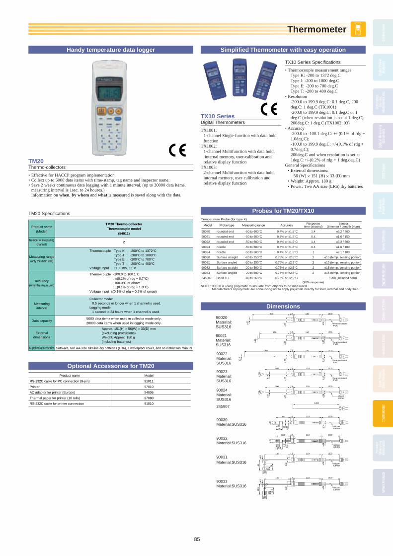
Thermometer
85
Ther
mom
eter
Osci
llosc
opes
Digi
tal P
ower
Anal
yzer
s
Gene
rato
rs,
Sour
ces,
Man
omet
ers
etc.
Optic
al M
easu
ring
Inst
rum
ents
Data
Log
ger
Clam
p-on
Pow
er M
eter
Hand
y Ca
libra
tor
Digi
tal M
ultim
eter
Clam
p-on
Tes
ter
Insu
latio
n Te
ster
Eart
h Te
ster
,Ot
her P
rodu
cts
Ther
mom
eter
Ther
mom
eter
Ther
mom
eter
Prec
isio
nM
easu
ring
Inst
rum
ents
Met
ers
Prod
ucts
TX10 SeriesDigital Thermometers
TX1001: 1-channel Single-func tion with data hold
func tionTX1002: 1-channel Multifunction with data hold,
in ter nal memory, user-cal i bra tion and relative dis play function
TX1003: 2-channel Mul ti func tion with data hold,
internal memory, user-cal i bra tion and relative dis play function
TX10 Series Specifi cations
• Thermocouple mea sure ment ranges Type K: -200 to 1372 deg.C Type J: -200 to 1000 deg.C Type E: -200 to 700 deg.C Type T: -200 to 400 deg.C • Resolution -200.0 to 199.9 deg.C: 0.1 deg.C, 200
deg.C: 1 deg.C (TX1001) -200.0 to 199.9 deg.C: 0.1 deg.C or 1
deg.C (when res o lu tion is set at 1 deg.C), 200deg.C: 1 deg.C (TX1002, 03) • Accuracy -200.0 to -100.1 deg.C: +/-(0.1% of rdg +
1.0deg.C); -100.0 to 199.9 deg.C: +/-(0.1% of rdg +
0.7deg.C); 200deg.C and when res o lu tion is set at
1deg.C:+/-(0.2% of rdg + 1 deg.deg.C) General Specifi cations • External dimensions: 56 (W) × 151 (H) × 33 (D) mm • Weight: Approx. 180 g • Power: Two AA size (LR6) dry batteries
Simplifi ed Thermometer with easy operation
TM20Thermo-collectors
• Effective for HACCP program implementation.• Collect up to 5000 data items with time-stamp, tag name and inspector name.• Save 2 weeks continuous data logging with 1 minute interval, (up to 20000 data items,
measuring interval is 1sec. to 24 houres.) Information on when, by whom and what is measured is saved along with the data.
90033Material:SUS316
90021Material:SUS316
90022Material:SUS316
90023Material:SUS316
90024Material:SUS316
245907
90030Material:SUS316
90031Material:SUS316
90020Material:SUS316
heat-resistantPVC
1200110200
φ 22 φ 14
φ 3.2
13
heat-resistantPVC
1200110150 13
φ 22 φ 14φ 1.6
heat-resistantPVC
1200110500 13
φ 22
φ 14
φ 3.2
heat-resistantPVC
1200110100 13
φ 22 φ 14
φ 1.6
45°
siliconrubber
1200110100 13
φ 22 φ 14
φ 2.1
45°
1200
siliconrubber
siliconrubber
1200110
1200110
56 12
55.5 12
26
14
25.513.5
φ 22φ 6
φ 22φ 6
φ 14
φ 14
φ 15
φ 15
siliconrubber
siliconrubber
1200110100 12
1200110100 12
φ 4.8
φ 4.8
φ15
φ15
φ 22
φ 22
φ 14
φ 14
4645
.5
14
2913
.5 28.5
90032Material:SUS316
Model
Temperature Probe (for type K)
90020
90021
90022
90023
90024
90030
90031
90032
90033
245907
rounded end
rounded end
rounded end
needle
needle
Surface straight
Surface angled
Surface straight
Surface angled
Bead TC
-50 to 600°C
-50 to 600°C
-50 to 600°C
-50 to 500°C
-50 to 500°C
-20 to 250°C
-20 to 250°C
-20 to 500°C
-20 to 500°C
-40 to 260°C
0.4% or ±1.5°C
0.4% or ±1.5°C
0.4% or ±1.5°C
0.4% or ±1.5°C
0.4% or ±1.5°C
0.75% or ±2.5°C
0.75% or ±2.5°C
0.75% or ±2.5°C
0.75% or ±2.5°C
0.75% or ±2.5°C
1.4
0.4
1.4
0.4
1
2
2
2
2
(90% response)
φ3.2 / 200
φ1.6 / 150
φ3.2 / 500
φ1.6 / 100
φ2.1 / 100
φ15 (temp. sensing portion)
φ15 (temp. sensing portion)
φ15 (temp. sensing portion)
φ15 (temp. sensing portion)
1200 (included cord)
Probe type Measuring range Accuracy Responsetime (second)
SensorDimenter / Length (m/m)
NOTE: 90030 is using polyimide to insulate from objects to be measured.Manufacturers of polyimide are announcing not to apply polyimide directly for food, internal and body fluid.
Probes for TM20/TX10
Dimensions
Approx. 151(H) × 56(W) × 33(D) mm (excluding protrusions)Weight: Approx. 180 g (including batteries)
TM20 Thermo-collectorThermocouple model
(54011)
Thermocouple Type K : -200°C to 1372°CType J : -200°C to 1000°CType E : -200°C to 700°CType T : -200°C to 400°C
Voltage input ±100 mV, ±1 V
2
Collector mode:0.5 seconds or longer when 1 channel is used.
Logging mode:1 second to 24 hours when 1 channel is used.
Thermocouple -200.0 to 100.1°C : ±(0.1% of rdg + 0.7°C)-100.0°C or above : ±(0.1% of rdg + 1.0°C)
Voltage input ±(0.1% of rdg + 0.2% of range)
Product name(Model)
Number of measuringchannels
Data capacity
Measuring range(only the main unit)
Accuracy(only the main unit)
Supplied accessories
Measuring interval
External dimensions
5000 data items when used in collector mode only,20000 data items when used in logging mode only.
Software, two AA-size alkaline dry batteries (LR6), a waterproof cover, and an instruction manual
TM20 Specifi cations
Model
91011
97010
94006
97080
91010
Product name
RS-232C cable for PC connection (9-pin)
Printer
AC adapter for printer (Europe)
Thermal paper for printer (10 rolls)
RS-232C cable for printer connection
Optional Accessories for TM20
Handy temperature data logger
BOOK_YMI130-EN 85 13.5.9, 11:03:23 AM

Precision Measuring Instruments
86
Prec
isio
nM
easu
ring
Inst
rum
ents
Osci
llosc
opes
Digi
tal P
ower
Anal
yzer
sGe
nera
tors
,So
urce
s,M
anom
eter
s et
c.
Optic
al M
easu
ring
Inst
rum
ents
Data
Log
ger
Clam
p-on
Pow
er M
eter
Hand
y Ca
libra
tor
Digi
tal M
ultim
eter
Clam
p-on
Tes
ter
Insu
latio
n Te
ster
Eart
h Te
ster
,Ot
her P
rodu
cts
Ther
mom
eter
Prec
isio
nPr
ecis
ion
Prec
isio
nM
easu
ring
Mea
surin
gM
easu
ring
Inst
rum
ents
Inst
rum
ents
Inst
rum
ents
Met
ers
Prod
ucts
2769Portable Double Bridge
Model 2769 is a compact, portable Kelvin double bridge designed for measuring low resistance from 0.1 mΩ to 110 Ω with four multiplication plugs and one measuring dial. It has built-in standard resistors, bridge power source and high-sensitivity taut-band suspension system electronic DC galvanom-eter.
2769 Specifi cations
Measuring Range: 0.1 mΩ* to 110 Ω.Measuring Dial: 1.00 to 11.00 Ω at × 1.Multipliers: × 0.0001*, × 0.001, × 0.01, × 0.1, ×
1, × 10 (plug-in system).Min. Division: 0.005 mΩ at × 0.0001*,
0.05 mΩ at ×0.001, 0.5 mΩ at × 0.01, 5 mΩ at × 0.1, 50 mΩ at × 1, 0.5 Ω at × 10.
Accuracy: ± (0.05 Ω × multiplier + 0.01 mΩ) Current Rating: 10 A at × 0.0001*
(0.01 Ω), 3A at × 0.001 (0.1 Ω), 1A at × 0.01 (1 Ω). 0.3A at × 0.1 (10 Ω), 0.1A at × 1 (100 Ω), 0.01A at × 10 (1,000 Ω).
Galvanometer: Built-in electronic DC gal-vanometer, voltage sensitivity ... approx. 20 µV/div.
sensitivity changeover; G0 ... (Input resistance: approx. 11 kΩ). G1 ... approx. 1/11 of G0 sensitivity. G2 ... approx. 1/110 of G0 sensitivity.Operating Temperature Range: 5 to 35°CHumidity Range: Less than 85% Bridge Power Source: Tow 1.5 V batteries,
External power source is also usable.*Note: Standard Resistor (Model 2771) is
required for measurement on 0.1 to 1.1 mΩ range at 0.0001 multiplier.
0.1mΩ to 110Ω with four plugs and one measuring dial
2755Portable Wheatstone Bridge
Model 2755 measures resistances from 1 Ω to 10 MΩ by operation of dials and switches. Batteries and a galvanometer are self-con-tained. The front control panel is provided with power and galvanometer circuit selec-tors, one ratio arm dial, and four measuring arm dials.
2755 Specifi cations
Measuring Range: 1,000 Ω to 10.00 Ω.Measuring Arms: 1Ω × 10 + 10 Ω × 10 + 100
Ω × 10 + 1,000 Ω × 10 (min. one step: 1 Ω).Ratio Arms (Multiplier): × 0.001, × 0.01, ×
0.1, × 1, × 10, × 100, × 1,000 (M10, M100, M1000 ... Murray & Varley loop testing).
Accuracy: ±0.1% of reading on 100 Ω to 100 kΩ range, ±0.3% of reading on 10 Ω to 1 MΩ range, ±0. 6% of reading on 1Ω to 10 MΩ range.
Temperature Coeffi cient of Resistance Elements: ±5 × 10⁻⁵/°C at ambient temperature of 5 to 35°C, ±2 × 10⁻⁵/°C at ambient temperature 20 to 35°C.
Galvanometer: Sensitivity ... 0.9 µA/div., inter-nal resistance ... Approx. 150 Ω, external critical damping resistance ... Approx. 800 Ω, period ... within 1.5 seconds.
Power Source: Three 1.5 V batteries (built-in).Operating Temperature Range: 5 to 35°C.Humidity Range: 85% max., relative humidity.Outer Case: ABS resin.Accessory supplied at no extra cost: Carrying case.
1Ω to 10MΩ by operation of dials and switches
2791 SeriesSlide Resistors
Model 2791 is composed of resistance wire with an insulating coating wound on a frame of special ceramic and a sliding brush that maintains contract with the wire. Resistance is continuously variable and can be increased or decreased as desired.
2791 series Specifi cations
Available Models:
Code Nominal ValueAllowable Input
Current
279101 4,800 Ω 0.18 A
279102 1,400 Ω 0.35 A
279103 600 Ω 0.5 A
279105 170 Ω 1.0 A
279108 39 Ω 2.0 A
279110 10 Ω 4.0 A
279112 4.7 Ω 6.0 A
Allowable Deviation: ±20% of nominal value.Insulation Resistance: More than 5 MΩ at
500 V DC between terminal and case.Dielectric Strength: 1,000 V AC for one min-
ute between terminal and case.
Used in testing laboratory and industrial test
278610/278620Decade Resistance Boxes
Models 278610 and 278620 six-dial decade resistance boxes allow quick and easy setting of a wide range of resistance. These resis-tance boxes are used in combination with voltage or current standards to adjust voltage or current, as dummy load resistances or as an arm of AC bridges.
278610/278620 Specifi cations
Available Models:
Model Number Resistance Range
278610 0.1 to 111,111 Ω (six decade dials)
278620 1 to 1,111,110 Ω (six decade dials)
Residual Resistance: Less than 23 mΩ.Power Rating: 0.3W/step, within 3W for over-
all instrument.Maximum Allowable Input: 0.5W/step, 5W
for overall instrument.Maximum Circuit Voltage: 250 V.Operating Temperature Range: 0 to 40°C Storage Temperature Range: -10 to 50°C Humidity Range: 25 to 85%, relative humidity.Insulation Resistance: More than 500 MΩ at
500 V DC.Dielectric Strength: 1,500 V AC for one minute.
Quick and easy setting
279301/279303Decade Resistance Boxes
279301• High accuracy and stability• High reproducibility• 1 mΩ resolution
279303• Up to 100 MΩ in 100 Ω step• Low voltage coeffi cient• Shock- and vibration-proof construction
279301 Specifi cations
Resistance Range: 0.100 to 1,111.210 Ω (Mini-mum resistance is 0.100 Ω).
Dial Composition: 0.001 × 10 + 0.01 Ω × 10 + 0.1 Ω × 11 + 1 Ω × 10 + 10 Ω × 10 + 100 Ω × 10
Resolution: 0.001 ΩAccuracy: ± (0.01% + 2 mΩ) at temperature
23 ± 2°C, humidity 45 to 75%, and 0.1 W power application
High-accuracy, DC variable resistor with 6 dials
2792A SeriesStandard Resistors
• Traced to the national standard for high ac-curacy; test (calibrated) accuracy of ±5 ppm
• Resistance temperature coeffi cient• A variety of models Eight models with nominal resistance val-
ues ranging between 0.001 Ω and 10 kΩ• Precision temperature control equipment,
such as an oil bath, not needed for calibra-tion due to marked improvement in resis-tance temperature coeffi cient
• Included document: Test certifi cate
2792A series Specifi cations
Metal foil resistors
Operating temperature and humidity ranges: 0-50°C / 20-80% RHMaximum allowable power: 3 WTest (calibrated) accuracy: ±5 ppmPower characteristics: ±100 ppm/WInsulation resistance: More than 1000 MΩ at 500 V DCWithstand voltage: 1.5 kV for one minute be-
tween measurement terminal and casingTerminal construction: 4 terminalsExternal dimensions: Approximately φ104 ×
150 mm (current terminal width: approxi-mately 174 mm)
Weight: Approximately 1.2 kgAccessories: User'S Manual, One Test Cer-
tifi cate
279303 Specifi cations
Resistance Range: 0 to 111. 1110 MΩ.
Dial Composition: 100 Ω × 10 + 1 kΩ × 10 + 10 kΩ × 10 + 100 kΩ × 10 + 1 MΩ × 10 + 10 MΩ × 10.
Accuracy: 100Ω, 1 kΩ, 10 kΩ and 100 kΩ steps ... ± (0.05% + 0.05Ω)
1 MΩ and 10 MΩ steps ... ±0.2% (At temperature 23 ± 2°C, humidity below
75%, including residual resistance of ap-prox. 0.05 Ω).
Model Nominal value Accuracy 23˚C±2˚C2792A01 0.001 Ω ±100ppm2792A02 0.01 Ω ±75ppm2792A03 0.1 Ω ±50ppm2792A04 1 Ω ±30ppm2792A05 10 Ω ±30ppm2792A06 100 Ω ±30ppm2792A07 1 kΩ ±30ppm2792A08 10 kΩ ±30ppm
BOOK_YMI130-EN 86 13.5.9, 11:03:29 AM

Meters Products
87
Met
ers
Prod
ucts
Osci
llosc
opes
Digi
tal P
ower
Anal
yzer
s
Gene
rato
rs,
Sour
ces,
Man
omet
ers
etc.
Optic
al M
easu
ring
Inst
rum
ents
Data
Log
ger
Clam
p-on
Pow
er M
eter
Hand
y Ca
libra
tor
Digi
tal M
ultim
eter
Clam
p-on
Tes
ter
Insu
latio
n Te
ster
Eart
h Te
ster
,Ot
her P
rodu
cts
Ther
mom
eter
Prec
isio
nM
easu
ring
Inst
rum
ents
Met
ers
Prod
ucts
Met
ers
Prod
ucts
Met
ers
Prod
ucts
Portable Instruments
2011 to 2053Portable Instruments
• Taut-band suspension system eliminates friction and provides strong resistance to shock impact.
• Stable performance for long term use.• Products have been widely used over many
years as an industry standard at various customers such as industries, power plants, research laboratories and schools, etc.
Line-up
DC Ammeters and Voltmeters 2011, 2012AC Ammeters and Voltmeters 2013, 2014High-frequency AC Ammeters and Voltmeters 2016Audio-frequency AC Voltmeters 2017Frequency Meters 2038Power Factor Meters 2039Wattmeters 2041, 2042Miniature DC Ammeters and Voltmeters 2051Miniature AC Ammeters and Voltmeters 2052, 2053
Switchboard Instruments
2100A SeriesSwitchboard Instruments
• Compliance with JIS C1102-2007
Line-up
DC Ammeters and Voltmeters 2101A, 2181AAC Ammeters and Voltmeters 2102A, 2182AWattmeters 2105A, 2185AVarmeters 2106A, 2186APower Factor Meters 2107A, 2187AFrequency Meters 2108A, 2188ASynchroscope 2109
Front Cover Dimensions (Width × Height mm)
210A 110×110218A 80×80
Panel Meters
Clearline Series and FS,FL SeriesPanel Meters
• Compliance with JIS C1102-2007• Clearline Series Two types of movement suspension sys-
tems, Taut-band and Pivot & Jewel, are available to fi t to various applications.
• FS,FL Series High visibility by adopting clear front
cover.
Line-up
• Clearline Series (2071 to 2076A, 2081 to 2086A, 2093A
and 2094A) DC Ammeters and Voltmeters, AC Amme-
ters and Voltmeters and Frequency Meters• FS,FL Series DC Ammeters and Voltmeters, AC Amme-
ters and Voltmeters, Frequency Meters, Wattmeters, Varmeters
and Power Factor Meters
Front Cover Dimensions (Width × Height mm)
2071, 2081: 52×442072, 2082: 57×482073, 2083: 69×582074A, 2084A: 82×69FL80: 80×672075A, 2085A: 102×85FL10: 100×832076A, 2086A: 122×1022093A, FS60: 60×602094A, FS80: 80×80FS10: 100×100
0.5 Class Transducer for Power Applications
2370A SeriesClass 0.5 Transducer for Power Applications
• Available for DIN rail and panel mountings
Line-up
DC-DC isolator 2371AAC Voltage, current (average rectifi ed) 2372AAC Voltage, current (RMS rectifi ed) 2373AAC Voltage, current (True RMS rectifi ed) 2374APower 2375AReactive power 2376APhase 2377APower factor 2377AFrequency 2378A
Dimensions (mm)
2371A, 2372A, 2373A, 2374A, 2378A: 127(H) × 40(W) × 130(D)2375A, 2376A, 2377A: 127(H) × 55(W) × 130(D)
201314 205206
Clearline Series FS,FL Series* Cover with set pointer
2105A 2188A
BOOK_YMI130-EN 87 13.5.9, 11:03:35 AM
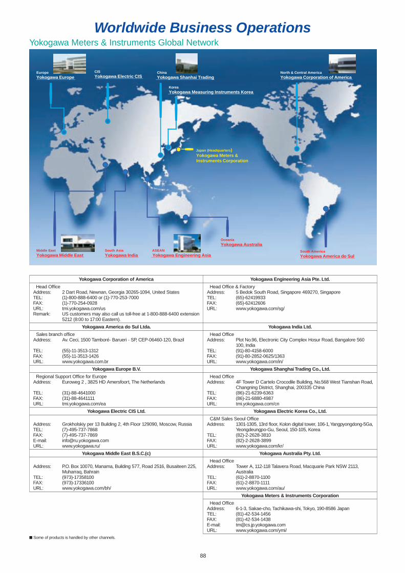
88
Worldwide Business OperationsYokogawa Meters & Instruments Global Network
Yokogawa Corporation of America Yokogawa Engineering Asia Pte. Ltd.
Head Offi ceAddress: 2 Dart Road, Newnan, Georgia 30265-1094, United StatesTEL: (1)-800-888-6400 or (1)-770-253-7000FAX: (1)-770-254-0928URL: tmi.yokogawa.com/usRemark: US customers may also call us toll-free at 1-800-888-6400 extension
5212 (8:00 to 17:00 Eastern).
Head Offi ce & FactoryAddress: 5 Bedok South Road, Singapore 469270, SingaporeTEL: (65)-62419933FAX: (65)-62412606URL: www.yokogawa.com/sg/
Yokogawa America do Sul Ltda. Yokogawa India Ltd.
Sales branch offi ceAddress: Av. Ceci, 1500 Tamboré- Barueri - SP, CEP-06460-120, Brazil
TEL: (55)-11-3513-1312FAX: (55)-11-3513-1426URL: www.yokogawa.com.br
Head Offi ceAddress: Plot No.96, Electronic City Complex Hosur Road, Bangalore 560
100, IndiaTEL: (91)-80-4158-6000FAX: (91)-80-2852-0625/1363URL: www.yokogawa.com/in/
Yokogawa Europe B.V. Yokogawa Shanghai Trading Co., Ltd.
Regional Support Offi ce for EuropeAddress: Euroweg 2 , 3825 HD Amersfoort, The Netherlands
TEL: (31)-88-4641000FAX: (31)-88-4641111URL: tmi.yokogawa.com/ea
Head Offi ceAddress: 4F Tower D Cartelo Crocodile Building, No.568 West Tianshan Road,
Changning District, Shanghai, 200335 ChinaTEL: (86)-21-6239-6363FAX: (86)-21-6880-4987URL: tmi.yokogawa.com/cn
Yokogawa Electric CIS Ltd. Yokogawa Electric Korea Co., Ltd.
Address: Grokholskiy per 13 Building 2, 4th Floor 129090, Moscow, RussiaTEL: (7)-495-737-7868FAX: (7)-495-737-7869E-mail: [email protected]: www.yokogawa.ru/
C&M Sales Seoul Offi ceAddress: 1301-1305, 13rd fl oor, Kolon digital tower, 106-1, Yangpyongdong-5Ga,
Yeongdeungpo-Gu, Seoul, 150-105, KoreaTEL: (82)-2-2628-3810FAX: (82)-2-2628-3899URL: www.yokogawa.com/kr/
Yokogawa Middle East B.S.C.(c) Yokogawa Australia Pty. Ltd.
Address: P.O. Box 10070, Manama, Building 577, Road 2516, Busaiteen 225, Muharraq, Bahrain
TEL: (973)-17358100FAX: (973)-17336100URL: www.yokogawa.com/bh/
Head Offi ceAddress: Tower A, 112-118 Talavera Road, Macquarie Park NSW 2113,
AustraliaTEL: (61)-2-8870-1100FAX: (61)-2-8870-1111URL: www.yokogawa.com/au/
Yokogawa Meters & Instruments Corporation Head Offi ce
Address: 6-1-3, Sakae-cho, Tachikawa-shi, Tokyo, 190-8586 JapanTEL: (81)-42-534-1456FAX: (81)-42-534-1438E-mail: [email protected]: www.yokogawa.com/ymi/
North & Central AmericaYokogawa Corporation of America
EuropeYokogawa Europe
South AmericaYokogawa America do Sul
CISYokogawa Electric CIS
Middle EastYokogawa Middle East
ASEANYokogawa Engineering Asia
ChinaYokogawa Shanhai Trading
KoreaYokogawa Measuring Instruments Korea
OceaniaYokogawa Australia
South AsiaYokogawa India
Japan (Headquarters)Yokogawa Meters &Instruments Corporation
Some of products is handled by other channels.
YMI130-EN_88-89.indd 88 13.5.9, 11:04:47 AM

89
http://tmi.yokogawa.com/
http://www.yokogawa.com/ymi/
Search
GLOBALHOME / 0ur Businesses /
The following Web site offer a variety of information and services, such as document download, software download, user registration, e-mail news subscriptionand other.
Our Web site will help you find what you look for.
The following Web site offer a variety of information and services, such as document download, software download, user registration, e-mail news subscriptionand other.
Our Web site will help you find what you look for.
Digital OscilloscopesDigital Power AnalyzersData Acquisition EquipmentOptical Measuring InstrumentsGenerators, Sources
MetersPortable Data StationsDigital Multimeters/Circuit TestersInsulation Testers/Earth TesterClamp-on Power MetersClamp-on TestersThermometersCalibratorsDC Precision Measuring InstrumentsEnvironmental Measuring InstrumentsOther Test & MeasurementInstruments
YMI130-EN_88-89.indd 89 13.5.9, 11:04:49 AM

All P
roducts Guide Test &
Measurem
ent Instruments/M
eters & P
ortab
le Instruments
Vol.2
Yoko
gaw
a Meters &
Instruments C
orp
oratio
n
Catalog YMI130-EN
Test & Measurement Instruments/Meters & Portable Instruments
Represented by:
YOKOGAWA CORPORATION OF AMERICA2 Dart Road, Newnan, GA. 30265-1094 U.S.A.Phone: +1-770-253-7000 Facsimile: +1-770-254-0928
YOKOGAWA EUROPE B. V.Euroweg 2 3825 HD Amersfoort, THE NETHERLANDSPhone: +31-88-4641000 Facsimile: +31-88-4641111
YOKOGAWA ENGINEERING ASIA PTE. LTD.5 Bedok South Road, Singapore 469270 SINGAPOREPhone: +65-6241-9933 Facsimile: +65-6241-2606
YOKOGAWA AMERICA DO SUL LTDA.Praca Acapulco, 31-Santo Amaro, Sao Paulo/SP, BRAZIL CEP-04675-190Phone: +55-11-5681-2400Facsimile: +55-11-5681-4434
YOKOGAWA ELECTRIC KOREA CO., LTD.C&M Sales Seoul Office1301-1305, 13rd floor, Kolon digital tower, 106-1, Yangpyongdong-5Ga, Yeongdeungpo-Gu, Seoul, 150-105, KoreaPhone: +82-2-2628-3810 Facsimile: +82-2-2628-3899
YOKOGAWA AUSTRALIA PTY. LTD.Tower A/112-118 Talavera Road Macquarie Park, NSW 2113 AustraliaPhone: +61-2-8870-1100 Facsimile: +61-2-8870-1111
YOKOGAWA INDIA LTD. Plot No. 96. Electronic City Complex, Hosur Road, Bangalore 560100, INDIAPhone: +91-80-4158-6000 Facsimile: +91-80-2852-1441
YOKOGAWA SHANGHAI TRADING CO., LTD. 4F Tower D, Cartelo Crocodile Building, No.568 West Tianshan Road, Shanghai, CHINAPhone: +86-21-6239-6363 Facsimile: +86-21-6880-4987
YOKOGAWA MIDDLE EAST B. S. C.(C)P.O.BOX 10070, Manama, Building 577, Road 2516,Busaiteen 225, Muharraq, BAHRAINPhone: +973-17-358100 Facsimile: +973-17-336100
YOKOGAWA ELECTRIC CIS LTD.Grokholskiy per. 13, Build. 2, 4th Floor, 129090, MoscowRUSSIAN FEDERATIONPhone: +7-495-737-7868 Facsimile: +7-495-737-7869
World Wide Web site athttp://tmi.yokogawa.com
NOTICE Before using the product, read the instruction manual
carefully to ensure proper and safe operation.
Tachihi Bld. No.2, 6-1-3 Sakaecho, Tachikawa-shi, Tokyo, 190-8586 JapanPhone: +81-42-534-1413 Facsimile: +81-42-534-1438
YOKOGAWA METERS & INSTRUMENTS CORPORATIONInternational Sales Dept.
Subject to change without notice. [Ed: 02/b] Printed in Japan: May 2013(A)/7,500(KP)All Rights Reserved. Copyright © 2011, Yokogawa Meters & Instruments Corporation.
MIK-EL18