Embed Size (px)
Citation preview

Alkaline Additions to the Backfill A KeyMining/Reclamation Component to Acid Mine
Drainage Prevention
Hans E. Naumann, P.E.
Senior Vice PresidentMarshall Miller & Associates
5480 Swanton DriveLexington, Kentucky 40509
Vance Patrick Wiram, CPG
Supervisor Environmental ServicesAMAX Coal CompanyOne Riverfront Place20 N. W. First Street
Evansville, Indiana 47708‐1258
ABSTRACT:
Skyline Coal Company, a wholly owned subsidiary of Cyprus Amax Coal Company, initiatedsurface mining of the Sewanee seam of coal in Sequatchie County, Tennessee in theSeptember, 1987, pursuant to the terms of a duly approved surface mining permit. The minewas named after an adjacent creek, Glady Fork. The engineering and geological studiesconducted in the preparation of the surface mining permit application indicated that themine could be operated with a minimum of concern for the generation of adverse impacts tothe hydrological regime outside of the permit area. On July 5, 1990, however, the mine wascited for polluting Glady Fork with iron laden seeps. Shortly thereafter, comprehensivehydrogeological, geochemical, and operations management investigations were launched.Furthermore, laboratory testing procedures were scrutinized and modified to address the"siderite masking" of overburden data generated from standard acid‐base accountingtechniques. These investigations culminated in the preparation of a detailed Toxic MaterialsHandling Plan (TMHP) which incorporated "state of the art" ground water management plansand water quality assurance programs. In light of the lithologic distribution of theproblematic strata and the reliance on both blast casting and dragline equipment foroverburden movement, the TMHP placed a heavy emphasis on the timeliness of certainactivities, the collection of detailed pre‐mining information, and the application of heavydoses of alkalinity in the form of crushed limestone. The permit area has been mined out andis currently in the final reclamation phases of pit closure. Data collection from various groundwater sources support the validity of the concepts and practices undergirding the TMHP.Significant alkaline loading of the backfill ground water resource has been realized. Moreimportantly, the alkaline additions of the TMHP have yielded substantial reductions in both

iron (Fe) and manganese (Mn) loading to the post‐mine ground water regime.
INTRODUCTION
Activities aimed at the prevention or abatement of poor quality mine drainage must be basedupon a well designed, fully implemented Toxic Materials Handling Plan (TMHP). The planshould be site specific in nature. Its overall effectiveness in meeting desired abatementobjectives will be contingent upon the prudent factoring of key hydrogeologic, geochemical,and operational considerations into its design and field application. In this case, alkalineadditions through imported limestone were a key component to the success of a TMHPdeveloped specifically for the Glady Fork Mine. This paper will document the merits of addinglimestone amendments to the backfill in coordination with surface coal mining andreclamation activities. Emphasis is placed on the benefits derived from adding the alkalinematerials along identified hydrologic flow‐paths in the backfill.
STATEMENT OF PURPOSE
The purpose of this paper is to share the experiences of Skyline Coal Company with the coalmining industry. In particular, the writers wish to address the following points of significance:
The methodologies involved with limestone incorporation to the backfill in synchronizationwith the surface mining and reclamation process requires a detailed knowledge of theoperation of the mine.
Limestone additions, with respect to both quantity and placement in the backfill mustbe based on overburden geochemical data. This data must be routinely gathered inadvance of mining.Time spent in identifying the post mining ground water regime and direction of flow isessential in developing concepts and defining the needed "building ‐ blocks" to achieveoverall effectiveness of the TMHP.The benefits of alkaline additions can be directly measured or observed by monitoringthe ground water quality of the backfill.
BACKGROUND
Skyline Coal Company is a small surface operation (<500,000 tons/year) located in SequatchieCounty, approximately 15 miles northwest of Dunlap, Tennessee. The subject mine is theGlady Fork Mine. Mining was initiated at the Glady Fork site in the September of 1987 in thelower third of the mining permit by use of endloaders and trucks. A box cut was preparedusing that equipment. Once the box cut was in place, a walking dragline was placed into thesequence, and the front end loaders and overburden trucks were subsequently phased out.Cast‐blasting was later introduced to the operations and subsequently the remainder of thepermitted area has been developed with a combination of both dragline and cast‐blasting asthe primary mode for overburden movement.
The coal‐bearing sequence developed at Glady Fork are Pennsylvanian Age rocks of the CrabOrchard Group. The overburden strata consist of the Newton Sandstone and Whitwell ShaleFormations. The coal seam being mined is the Sewanee Coal Member of the Whitwell Shale

Formation. The surface mine is in a broad upland divide area of the Cumberland Plateau. Itlies between major drainage systems which dissect the plateau surface. The major streamadjacent to the former mine site is Glady Fork Creek.
In mid‐ 1990, Skyline Coal began experiencing water problems at Glady Fork. 'Me waterconcerns were in the form of off‐site seepage emanating from the mine site into the adjacentcreek. The seepage consisted of slightly acidic to alkaline, manganese (Mn) enriched,ferruginous waters. Seepage flows were defined as originating from the mine disturbanceareas with movement to the creek via natural fracture systems or other stratigraphic flowpaths existing in the stream buffer zone and stream bed itself. Although the overall impactsof the seepage to the adjoining streams were limited to aesthetics (red staining) andtemporary benthic aquatic habitat concerns (iron sediment coatings), the discharge wasdefined as a pollution source to waters of the State and therefore implementation ofremedial action plans were required to eliniinate or minimize degradation potentials.
The range in primary water quality parameters of the seeps at the time of discharge were asfollows: pH = 3.4 to 7.5; alkalinity = 0 to 121 mg/l; total iron (Fe) = 4.8 to 48.6 mg/l; totalmanganese (Mn) = 2.3 to 34 mg/l; and, sulfate (SO4) = 8 to 812 mg/l.
Skyline embarked on an intensive investigative program so that enough information could becollected to identify the cause of the apparent disparity between the projected and actualwater quality parameters. This information was also deemed necessary in order that areliable materials handling plan could be developed which would pass muster by both theregulatory authorities and corporate custodians. This program included extensive coredrilling, testing of overburden samples, and modifying the testing procedures to account for"siderite masking" of acid/base overburden characterization objectives (Wiram, 1992), re‐examining the hydrogeological and geochemical structure of the overburden, and consultingwith experts in the field of mine drainage. Contrary to earlier permit findings, the additionalsite investigations identified potential acid‐producing strata that were previously ill‐definedor non‐existent based upon acid/base laboratory procedures that did not account for theabundance of siderite (FeCO3) common to the overburden shale sequence.
Using modified analytical procedures to account for the "siderite masking", three stratigraphichorizons in the overburden were identified as being potentially acid‐producing in character.The three horizons were (listed in descending order):
1. upper shales (<5.0') at the top of the Whitwell Shale Formation;2. lenticular sandy shales (0 ‐ 20') within the Whitwell; and,3. pit floor or underclay of the Sewanee Seam.
A fourth type of material, the "coal cleanings" (an admixture of coal and underclay),generated in the coal extraction process, was also identified as being acid‐producing incharacter and was subsequently targeted for proper handling and disposal during mining.
Although the different materials were demonstrated to possess pyritic materials and a lack ofinherent neutralizing potentials, the acid producing character of the various strata was onlysporadic in nature. With the exception of the "coal cleanings", it was not uncommon to seeboth acid and alkaline characteristics within the respective strata.

Typical ranges in % pyritic sulfur (%PS) contents and modified net neutralization potentials(MNNPs, expressed as tons of CaCO3 /1000 tons material) for identified acid producing unitswere as follows:
1. Upper shales: %Ps = <0.1 to 1.64, and MNNP = ‐26 to +55.2. Sandy shale: % Ps = <0.1 to 1.7 8, and MNNP = ‐48 to + 143. Underclay: %Ps = 0.12 to 0.78, and MNNP = ‐19 to +20
The typical range in both %Ps and MNNP observed for the coal cleanings were 0.73% to 1.60%and ‐45 to ‐24 tons CaCO3/1000 tons material respectively.
Throughout the reserve area, the lower Whitwell Shale interval above the coal seamdemonstrated consistently low %Ps and was alkaline in character. The Newton Sandstone, therock unit comprising the majority of the stratigraphic column of the coal sequence, wasshown to be basically inert from the standpoint of acid or alkaline producing potentials dueprimarily to its indurated, quartzitic cementation. An exception to the general rule for thesandstone interval existed when, on an occasional basis, the quartzitic cementation wasreplaced by sparry calcite. Although the calcite cementation was sporadic in occurrence,when present, such sandstone material demonstrated excess alkalinity characteristics withMNNP values commonly in the range of 100 to 130 tons of CaCO3/1000 tons material.
Eventually, these investigations, mine planning efforts, negotiations with the regulatoryauthorities, and protracted hearings at the administrative law level, generated a TMHP whichwas attributed the highest probability of success. The balance of this presentation describesthe results of the application of this TMHP.
THE MINING METHOD
Skyline's method for selectivity handling and disposing of potentially acid‐producing materialsinvolved a combination of operating techniques. Overburden movement was achieved by acombination of direct cast‐blasting, tractor pushing, and dragline placement with the mine'sBucyrus‐Erie Model 1300 stripping machine.

Skyline modified some phases of its traditional mining methods to accommodate the TMHPdeveloped for the site. An important element of change was that Skyline moved the backfill‐side operating bench level of the dragline from 50 feet or less off the pit floor to 85 feetabove the coal. That change enhanced the machine's capabilities of handling an increasingvolume of shale (i.e., problematic shale) to be placed on the bench pad as well as expanding the machine's ability to Place the best shale materials in the graded backfill. Both activitieswere deemed important to the success of the TMHP.
The mining sequence was initiated with the cleaning of the mined out pit, placement ofcleanings against the toe of the machine bench, and where appropriate, constructing ahydrologic flow‐path (chimney drain) to move subsurface water off the dragline bench itself.As other sections of this paper will discuss, this phase of the mining/reclamation sequencewas also the recipient of alkaline additions. The pre‐blast configuration as well as thegeneralized geochemical characterization of the overburden are depicted in the followingschematic.
The next schematic illustrates the position of the muck pile (shot overburden) following anormal cast‐blast shot. (The shape and the distribution of the shattered rock was initiallyestablished by field measurements. Thereafter, the services of blasting specialists usingspecial cameras were also secured. Dramatic "stop frame photography of the blasts supportthese initial field observations.) Note that the problematic shale extends across the formerpit floor. However, the bulk of the acid‐forming shale lies toward the highwall side of the pitand thus in a more advantageous position for selective handling with the dragline. Lastly, it isimportant to note that the shot rock underlying the entire length of the muck pile consists ofalkaline shale materials derived from the basal section of the original overburden profile.
Once the overburden material was cast, tractors were used to push the upper sections of themuck pile ("the bread loaf') from the highwall side toward the adjacent backfill bank.Eventually the tractors would cut into the shattered problematic shale and the pushedmaterial would become an admixture of problematic shale and inert sandstone. This uniqueconfiguration is depicted in Figure 4 on the following page.
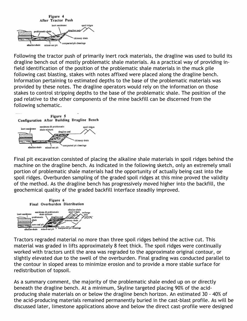
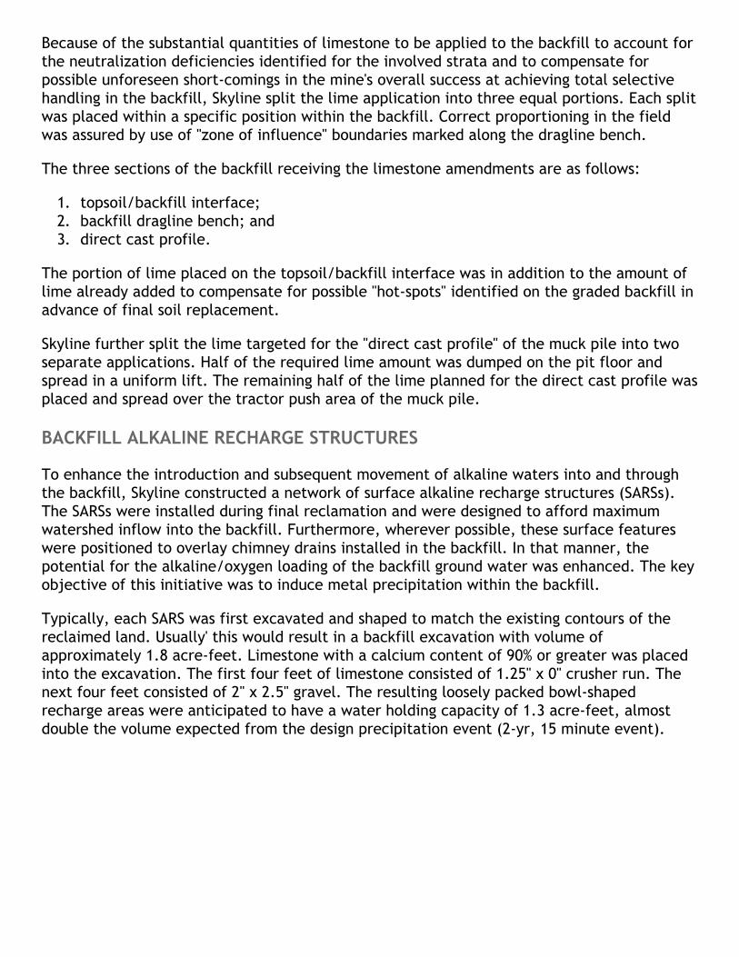
Following the tractor push of primarily inert rock materials, the dragline was used to build itsdragline bench out of mostly problematic shale materials. As a practical way of providing in‐field identification of the position of the problematic shale materials in the muck pilefollowing cast blasting, stakes with notes affixed were placed along the dragline bench.Information pertaining to estimated depths to the base of the problematic materials wasprovided by these notes. The dragline operators would rely on the information on thosestakes to control stripping depths to the base of the problematic shale. The position of thepad relative to the other components of the mine backfill can be discerned from thefollowing schematic.
Final pit excavation consisted of placing the alkaline shale materials in spoil ridges behind themachine on the dragline bench. As indicated in the following sketch, only an extremely smallportion of problematic shale materials had the opportunity of actually being cast into thespoil ridges. Overburden sampling of the graded spoil ridges at this mine proved the validityof the method. As the dragline bench has progressively moved higher into the backfill, thegeochemical quality of the graded backfill interface steadily improved.
Tractors regraded material no more than three spoil ridges behind the active cut. Thismaterial was graded in lifts approximately 8 feet thick. The spoil ridges were continuallyworked with tractors until the area was regraded to the approximate original contour, orslightly elevated due to the swell of the overburden. Final grading was conducted parallel tothe contour in sloped areas to minimize erosion and to provide a more stable surface forredistribution of topsoil.
As a summary comment, the majority of the problematic shale ended up on or directlybeneath the dragline bench. At a minimum, Skyline targeted placing 90% of the acid‐producing shale materials on or below the dragline bench horizon. An estimated 30 ‐ 40% ofthe acid‐producing materials remained permanently buried in the cast‐blast profile. As will bediscussed later, limestone applications above and below the direct cast‐profile were designed

to prevent and/or substantially minimize acid production from this zone of the backfill.
DESIGN OBJECTIVE OF ALKALINE ADDITIONS
The limestone applications had to meet both interim and long‐term requirements. A synopsisof the key amendment objectives follows:
1. To subdue bacterial pyritic oxidation activities and neutralize acidities generated fromunavoidable reactions occurring with the potentially acid‐producing materials (i.e.,Whitwell interface shale and lenticular sandy shale deposits, coal cleanings, underclaymaterials, etc.) exposed between stripping cycles and those subject to possibleoxidation once disposed in the backfill.
2. To focus alkaline recharge capabilities along predefined hydrologic flow‐paths (i.e.,dragline bench, graded backfill/topsoil interface, pit floor, etc.) to enhance long‐termalkaline loading in the backfill for the purpose of combating unfavorable aciditybuildup. (Coarse‐sized (11/2" x 0") limestone was used in order to sustain longevity ofthe alkaline resource.)
3. To enhance the stability field of siderite (FeCO3) common to the shale materialscomprising the overburden sequence and to subsequently minimize this identifiedmineral as a contributing source of metal‐loading to the backfill. Addition of thelimestone was to sustain high alkalinity/acidity ratios in the backfill and thus maintainfavorable pH/alkaline conditions conducive to abatement of mineral dissolution.
4. The proposed added limestone to the base of the muck pile was to compliment the insitu alkaline shale materials. The combination of the limestone and alkaline shale wasto ensure availability and maintenance of alkalinity levels sufficient to effectively treatany acid reactions and subsequent metal‐loading activities that could accompanynatural backfill weathering processes (i.e., "wetting" and "drying" cycles) associatedwith backfill ground water re‐establishment.
KEY METHODS, PARAMETERS, AND ASSUMPTIONS
1. Overburden was sampled ahead of mining on a close‐spaced grid (approximately 500feet) using air‐rotary or core recovery methods. Individual samples were collected at 5‐foot vertical intervals in each exploratory hole.
2. All amendment rates associated with alkaline additions to the backfill were determinedby utilizing the modified neutralization potential (MNP) procedure for the purpose ofeliminating "siderite masking". MNP was expressed in terms of tons CaCO3/1000 tons ofmaterial.
3. The standard multiplication factor of 31.25 times the pyritic sulfur content was used incalculating potential acidities (PAs) of the various overburden materials. Potentialacidities were expressed in terms of tons CaCO3/1000 tons of material.
4. Modified Net Neutralization Potential (MNNP) was defined as the difference betweenMNP and PA (MNNP = MNP ‐ PA).
5. In defining its lime requirements, Skyline Coal used a 2,300 tons/ac.‐ft. factor forestimating tonnages of overburden shale and pit cleanings to be encountered instripping. This is a "Caterpillar Handbook" value. A 250 foot radius around each hole wasused to estimate the total quantity of alkalinity required.

6. Limestone application rates were based on "negative MNNP" zones identified in eachborehole. These were also denoted as "net deficient" zones. Individual net deficiencies(tons CaCO3/1000 tons of material) were deemed applicable to the 5‐foot interval fromwhich they were determined. A "cut‐off' was set at a "net deficiencies" equal to orgreater than 5 tons CaCO3/1000 tons of material.
7. The alkalinity of "net neutral" zones in each exploratory hole was not factored into thelimestone quantity estimation calculations.
8. Limestone application rates were based on a stone quality of 90% purity.
ALKALINE ADDITION PLACEMENT IN THE BACKFILL
The "building blocks" needed to develop a workable TMHP relative to the following issuesbegan to accumulate as the investigations proceeded:
1. The water quality characteristics of the earlier mined and backfilled portions of themine, as evidenced by both post‐mine ground water data and off site seepage waterquality;
2. The refinement of pre‐mine/post‐mine positioning of potentially acid‐producingmaterials in the stripping sequence; and,
3. The establishment of a basic understanding of the hydrologic flow‐paths in the backfill.
It quickly became evident that alkaline additions to the backfill would play a major part inthe TMHP. These additions were to have the dual role of minimizing and/or preventing acidicreactivity in the backfill and to enhance alkaline‐loading for meeting long‐term post‐minedrainage objectives following reclamation. The overall concepts for the design and plannedinstallations of alkaline‐loading mechanisms (i.e., SARS, hydrologic flow‐path liming, etc.) forthe TMHP are credited primarily to the past research works and technical papers of Caruccioand Geidel, 1988 and 1989. The ideas and technical support for incorporating the limestonematerials into the backfill in conjunction with the stripping and reclamation process stemprimarily from the works of Byerly (1990) and Infanger and Hood (1980).
Eight zones in the backfill were targeted for alkaline additions. The zones are (in descendingorder from the reclaimed surface):
1. replaced topsoil;2. topsoil‐graded backfill interface;3. backfill‐side dragline bench;4. pit‐direct cast overburden;5. pit‐direct cast understory;6. coal cleaning;7. pit floor underclay/shale; and,8. surface alkaline recharge structures (SARS).
Because of the substantial quantities of limestone to be applied to the backfill to account forthe neutralization deficiencies identified for the involved strata and to compensate forpossible unforeseen short‐comings in the mine's overall success at achieving total selectivehandling in the backfill, Skyline split the lime application into three equal portions. Each splitwas placed within a specific position within the backfill. Correct proportioning in the fieldwas assured by use of "zone of influence" boundaries marked along the dragline bench.
The three sections of the backfill receiving the limestone amendments are as follows:
1. topsoil/backfill interface;2. backfill dragline bench; and3. direct cast profile.
The portion of lime placed on the topsoil/backfill interface was in addition to the amount oflime already added to compensate for possible "hot‐spots" identified on the graded backfill inadvance of final soil replacement.
Skyline further split the lime targeted for the "direct cast profile" of the muck pile into twoseparate applications. Half of the required lime amount was dumped on the pit floor andspread in a uniform lift. The remaining half of the lime planned for the direct cast profile wasplaced and spread over the tractor push area of the muck pile.
BACKFILL ALKALINE RECHARGE STRUCTURES
To enhance the introduction and subsequent movement of alkaline waters into and throughthe backfill, Skyline constructed a network of surface alkaline recharge structures (SARSs).The SARSs were installed during final reclamation and were designed to afford maximumwatershed inflow into the backfill. Furthermore, wherever possible, these surface featureswere positioned to overlay chimney drains installed in the backfill. In that manner, thepotential for the alkaline/oxygen loading of the backfill ground water was enhanced. The keyobjective of this initiative was to induce metal precipitation within the backfill.
Typically, each SARS was first excavated and shaped to match the existing contours of thereclaimed land. Usually' this would result in a backfill excavation with volume ofapproximately 1.8 acre‐feet. Limestone with a calcium content of 90% or greater was placedinto the excavation. The first four feet of limestone consisted of 1.25" x 0" crusher run. Thenext four feet consisted of 2" x 2.5" gravel. The resulting loosely packed bowl‐shapedrecharge areas were anticipated to have a water holding capacity of 1.3 acre‐feet, almostdouble the volume expected from the design precipitation event (2‐yr, 15 minute event).

GROUND WATER MONITORING RESULTS
The application of the TMHP is now running into its third year. A review of the water qualitytrends from the majority of the backfill monitoring wells indicates an overall amelioration ofthe ground water associated in areas mined prior to the application of the TMHP. Theimprovement in ground water quality in the areas mined prior to full implementation of theTMHP initiative primarily reflects the combined benefits of contemporaneous reclamation andthe backfill's inherent capabilities to control the chemical reactions which generate poorquality water. The water quality trends within and adjacent to those areas that had thedirect benefits of the TMHP clearly demonstrate the prevention of significant deterioration ofthe ground water. The following discussions and graphic presentations summarize theseobservations.
Water quality data generated from five backfill ground water wells are presented here. Thefive wells (listed in order from south to north through the mined reserve) are OW‐2, OW‐5,OW‐7, OW‐10, and OW‐8. Some discussion of the location of these wells is required.
Wells OW‐2, 5, 7, and 10 are similar in that they fall outside fully implemented TMHPareas. These four wells reflect backfill conditions for approximately 90% of the totalarea mined at Glady Fork. OW‐2 and 5 share additional likenesses in that both arelocated down gradient from SARSs.OW‐7 is located approximately 1,300 feet northeast of OW‐5 and along the easternmosthighwall perimeter of the mined area. 'Me well is positioned over a structural low areaon the former pit‐floor and is within the projected post‐mine hydrologic flowpath of thebackfill.OW‐8, located approximately 800 feet south of the final pit, is positioned within thebackfill where full implementation of the TMHP has taken place. The well wasstrategically placed for the very purpose of monitoring the overall effectiveness of theTMHP on the post‐mine ground water system. Although OW‐7 lies down gradient of OW‐8, both wells are hydrologically connected in that the location of each well falls withinthe overall post‐ mine hydrologic flow pattern.OW 10 is offered here as a stark contrast primarily to OW‐7 and OW‐8. This observationwell was deliberately placed in a shallow backfill area, known for its preponderance ofproblematic shales, and its anticipated high position in the ground water regime of thebackfill. It was concluded early on, that this well would at best monitor the results ofcontemporaneous reclamation and possibly the influence of previous backfill/interface

liming activities only. The area around this well was not the beneficiary of the directapplication of the TMHP, and it had little or no chance of enjoying TMHP benefitsthrough ground water migration.
Five ground water quality parameters are discussed here for the purpose of demonstratingthe overall effectiveness of the TMHP in meeting the desired post‐mine reclamation goal ofminimizing backfill ground water deterioration. The five parameters to be highlighted arealkalinity, pH, sulfate (SO4), total manganese (Mn), and total iron (Fe). With the exception tothe sulfate, all the parameters chosen for comparative evaluations align with the mine'scurrent post‐mine NPDES effluent standard requirements. For sake of brevity, thecomparative discussions offered below address the overall performance of the differentquality parameters from a time‐trend perspective. The graphic presentations provided depicta statistically computed trend line reflecting overall performance of the respectiveparameters as measured since initiation of monitoring at the individual wells involved.
BACKFILL GROUND WATER ‐ ALKALINITY
Figure 9 depicts the various alkalinity trends established for the selected wells in the backfill.
The elevated positions of the trend lines for the hydrologically connected wells OW‐7 andOW‐8 clearly illustrate the positive effects of the alkaline additions. Although not discerniblefrom this simplified graph, up until March of 1994, the slope of the alkalinity trend for OW‐8was greater than that of OW‐7, and individual readings actually were higher that those ofOW‐7. Pit dewatering activities associated with final pit closure, however, lowered the nextseries of readings for OW‐8 by an estimated 50 to 60 mg/l during the summer and fall of1994. This temporary operational impact explains the currently observed position of the OW‐8alkalinity trend below that of OW‐7. Despite these unavoidable operational manipulations,the average alkalinity value for ground water in the vicinity of OW‐8 is an impressive 433mg/l. The maximum recorded alkalinity for the 2 1/2 year time period of monitoring is 537mg/l.
As previously mentioned, both OW‐7 and OW‐8 wells are positioned within the primary post‐mine hydrologic flow‐path in the backfill. OW‐7 is located in an area which had not beensubject to the TMHP. OW‐8, on the other hand, is located within a TMHP area. OW‐7 pre‐dates OW8 and is hydrologically downgrudient of OW‐8. Despite the fact that OW‐7 liesapproximately 2,100 feet from OW‐8, its high ground water alkalinity values reflectdowngradient migration of alkaline charged waters from the TMHP area.

North‐to‐south ground water movement has resulted in a significant "pooling" of alkaline‐loaded waters in the structural low area in the backfill at OW‐7. The ground wateraccumulated in the vicinity of OW‐7 has not only been the beneficiary of alkaline‐loadingfrom the upgradient TMHP area, it has also been the recipient of alkaline‐loading from bothsurface alkaline recharge as well as backfill/interface liming initiatives. These additionalsources of alkaline‐loading explain the observed high alkalinity levels recorded at OW‐7.
Observation wells OW‐5 and OW‐2 are functionally similar in that both measure backfillground water conditions at a considerable distance (3,000 feet and 4,500 feet respectively)from the TMHP area. However, both wells are positioned down‐gradient of SARSs. Theydemonstrate alkaline‐loading in those areas of the backfill where basically no limestoneadditions have been made. As indicated by the graph, both wells show favorable trends inincreased alkaline loading with time. Average alkalinity levels observed for ground water atOW‐5 and OW‐2 are 159 mg/l and 140 mg/l respectively.
The elevated alkalinity trend observed for OW‐5 reflects the dissolution of limestone withinthe SARS under the influence of both natural precipitation and operational pump‐backrecharge to the backfill. OW‐2 reflects a similar trend toward increased alkaline‐loading.However, the overall trend line is depressed below OW‐5 due to the longterm influence ofpast backfill dewatering activities associated with adjacent sediment pond modifications.
Ground water in the vicinity of OW‐10 displays a slight negative trend in alkalinity. This trendundoubtedly reflects the consumption of alkalinity in response to past and/or current naturalacidification/neutralization activities in the backfill. Despite the apparent decline in naturalalkalinity depicted by the graph, the inherent backfill carbonate resources appear to beeffective in maintaining favorable alkalinity levels in the ground water.
BACKFILL GROUND WATER ‐ pH
The benefits of the alkaline additions to the backfill can also be discerned from a trend linegraph of pH values for the ground water collected from the selected wells.
The pH values at both OW‐7 and OW‐8 ground water wells have remained within the 6.0‐7.0range. The slight negative trend in pH observed for OW‐8 reflects pit‐dewatering/final closureactivities. No pH conditions have been recorded which might indicate adverse acidificationactivities in this part of the Glady Fork backfill.
The steady pH performance observed at OW‐7 reflects the cumulative benefits of both
recharge contributions from the SARSs and subsurface ground water recharge from the TMHParea. OW‐Ts distance from any significant draw‐down impacts associated with pit/dewateringactivities provides a further explanation of the consistency of the pH values observed at thiswell location.
OW‐5 is located in backfill that had not been the recipient of the TMHP. It is locateddowngradient of an SARS. Considering the past backfill‐dewatering activities and thesubsequent manipulations of the ground water regime nearby (in the vicinity of OW‐2) it isapparent that the surface alkaline recharge structure up‐gradient from this well has played abeneficial role in maintaining steady state pH conditions in the backfill. Evidence indicatesthat the backfill ground water conditions have gone from acidic pHs (<6.0) to more favorablepHs (>6.0) in less than a 2 1/2 year period following reclamation.
A major segment of the monitoring well‐screen for OW‐5 is positioned in pit cleanings. Thesteady pH recorded for OW‐ 10 (pH = 6.0± range) reflects the presence of natural alkalineresources in the backfill and the benefits derived from the inundation of coal‐cleaningspositioned at the base of the backfill.
BACKFILL GROUND WATER SULFATES (SO4)
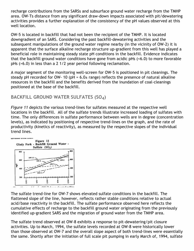
Figure 11 depicts the various trend‐lines for sulfates measured at the respective welllocations in the backfill. All of the sulfate trends illustrate increased loading of sulfates withtime. The only differences in sulfate performance between wells are in degree (concentrationlevels), as indicated by positioning of respective trend‐lines on the graph, and the rate ofproductivity (kinetics of reactivity), as measured by the respective slopes of the individualtrend lines.
The sulfate trend‐line for OW‐7 shows elevated sulfate conditions in the backfill. Theflattened slope of the line, however, reflects rather stable conditions relative to actualacid/base reactivity in the backfill. The sulfate performance observed here reflects thecumulative effects of recharge to the backfill ground water originating from the previouslyidentified up‐gradient SARS and the migration of ground water from the TMHP area.
The sulfate trend observed at OW‐8 exhibits a response to pit‐dewatering/pit closureactivities. Up to March, 1994, the sulfate levels recorded at OW‐8 were historically lowerthan those observed at OW‐7 and the overall slope aspect of both trend‐lines were essentiallythe same. Shortly after the initiation of full scale pit pumping in early March of, 1994, sulfate

concentrations at OW‐8 increased steadily. This is attributed to the "flushing" of the backfillmaterials as ground water levels in the backfill near that hole were caused to fluctuate. Onesignificant observation that can be made from the data is that sufficient alkaline materialsare present in the backfill to mitigate the effects of the acidic reactions. Thus both acid‐loading and metal‐loading have been minimized or prevented.
The slopes observed for the sulfate trends measured at both OW‐5 and OW‐2 somewhat mirrorthe trending sulfate levels observed for OW‐8. As with OW‐8, the overall sulfate trends forboth wells reflect significant influences from past and present mechanical manipulations ofthe ground water regime. Surface water pump‐back activity to the SARS up‐gradient of OW‐5has induced frequent "flushing" of the backfill. Both pump‐back and backfill‐dewatering hassignificantly influenced the overall sulfate‐loading in the vicinity of OW‐2. Undoubtedly inboth situations, some backfill acid/base reactivity has accompanied such mechanicalinfluences. The ground water quality data supports the conclusion, however, that the overallimpacts of undesired reactions have been minimized by the alkalinity releases from the SARSand the natural alkaline resources of the backfill materials.
In comparison to measurements made at all other observation wells at Glady Fork, the sulfateconcentrations at OW‐ 10 have been consistently higher. The elevated sulfates coupled withthe slight increase in sulfate productivity over time is associated with a backfill situationwhere greater than normal proportions of pyritic‐bearing backfill and coal‐cleanings arepresent and the benefits derived from fully implemented TMHP are lacking.
BACKFILL GROUND WATER METAL LOADING Fe and Mn
The benefits of alkaline additions is further evidenced by the significant reductions in metal‐loading to the backfill ground water regime. Trend comparisons of metal concentrations ofboth Fe and Mn reveal the positive effects of the alkaline additions in preventing orsignificantly minimizing development of undesirable acid conditions and restraining metaldissolution in the backfill. Figures 12 and 13 below illustrate the overall trends of both metalsfor each of the wells under consideration here. The following discussions briefly highlight keyobservations made from the trend analyses provided.
Manganese (Mn) ‐ Within the backfill area where full implementation of the TMHP has takenplace, a significant reduction in Mn‐loading is observable at OW‐8 Using a calculated mean of14 mg/I for Mn data generated at OW‐ 10 for comparison purposes, a 3.5X to 4X foldreduction in manganese dissolution has been achieved at OW‐8. Over the 2.5 year time‐periodof monitoring at OW‐8, the Mn levels have fluctuated from 1.8 to 8.1 mg/I and averaged 3.7
mg/l. As depicted in Figure 12, the Mn trend‐line at OW‐8 is climbing. This negative trend isskewed upward by recent pit‐dewatering/final pit closure activities. Prior to the pitdewatering events at Glady Fork, the Mn performance fell in the range of 1.8 to 4.0 mg/l.These values are consistent with post‐mine NPDES effluent discharge standards.
The progressive decline in Mn concentrations observed at OW‐7 reflect the positive effects ofhighly alkaline, low Mn‐bearing ground water generated in the TMHP area migratingsouthward toward OW‐7. At OW‐7, a 2.5X to 3X fold reduction in Mn‐loading can be observedwhen compared to ground water quality at OW‐10. From initial monitoring at OW‐7, the Mnlevels have varied from 1.80 mg/I to 9.30 mg/l. The last year values cluster around 5 mg/land are trending downward.
The continued mechanical manipulation and associated "flushing" of the backfill as a result ofpump‐back activities and pit dewatering have influenced the overall Mn trend‐lines for bothOW‐5 and OW‐2. Their concentrations of Mn are high. A favorable trend in Mn reductions atOW‐2 was noted following the halt of pump‐back and backfill dewatering activities. Thissuggests that this parameter will be reduce with time.
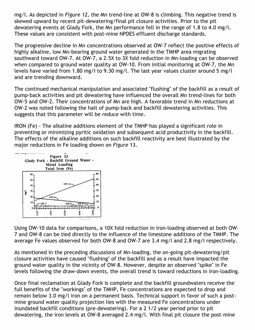
IRON (Fe) ‐ The alkaline additions element of the TMHP has played a significant role inpreventing or minimizing pyritic oxidation and subsequent acid productivity in the backfill.The effects of the alkaline additions on such backfill reactivity are best illustrated by themajor reductions in Fe loading shown on Figure 13.
Using OW‐10 data for comparisons, a 10X fold reduction in iron‐loading observed at both OW‐7 and OW‐8 can be tied directly to the influence of the limestone additions of the TMHP. Theaverage Fe values observed for both OW‐8 and OW‐7 are 3.4 mg/I and 2.8 mg/I respectively.
As mentioned in the preceding discussions of Mn‐loading, the on‐going pit‐dewatering/pitclosure activities have caused "flushing" of the backfill and as a result have impacted theground water quality in the vicinity of OW‐8. However, despite an observed "spike" in Felevels following the draw‐down events, the overall trend is toward reductions in iron‐loading.
Once final reclamation at Glady Fork is complete and the backfill groundwaters receive thefull benefits of the "workings" of the TMHP, Fe concentrations are expected to drop andremain below 3.0 mg/l iron on a permanent basis. Technical support in favor of such a post‐mine ground water quality projection lies with the measured Fe concentrations underinundated backfill conditions (pre‐dewatering). For a 2 1/2 year period prior to pitdewatering, the iron levels at OW‐8 averaged 2.4 mg/l. With final pit closure the post‐mine

ground water quality should stabilize in the 2.4 to <3.0 mg/l range.
The on‐going pump‐back/surface alkaline recharge activities associated with OW‐5 provides aplausible explanation for the slight negative trend in iron‐loading associated with this well. Areversal in trend can be expected once these operations are halted. Iron concentration trendsdepicted for OW‐2 provides a technical basis for that expectation. As indicated in Figure 13,OW‐2 Fe concentrations show a steady reduction over time. This favorable trend wasaccelerated following completion of pump‐back and backfill ‐dewatering activities in thevicinity of that well.
When all mechanical manipulations of the backfill ground water regime are terminated, it isexpected that continued declines in iron‐loading will be achieved. Such favorable trends inthe backfill ground water will ensure long‐term effectiveness of passive wetlands designed forhandling post‐mine water quality discharges from the southern end (Pre‐TMHP area) of theGlady Fork Mine.
CONCLUSIONS AND RECOMMENDATIONS
In review of the overall design objectives of the TMHP, in particular the element of limestoneadditions, the ground water data generated from monitoring the ground water in the GladyFork backfill indicate significant benefits have been derived. In fact, the monitoring datareflect that all of the basic design criteria and related objectives built into the TMHP arebeing met. The following summary highlights salient observations, interpretative inferences,and conclusions drawn from the monitoring data collected to‐date.
Limestone additions to the backfill have been effective in subduing bacterial pyriticoxidation activities during and following mining. The persistent high alkalinities and thecomplementing favorable pH conditions indicate that pyritic oxidation reactions havebeen significantly minimized or prevented.The consistently high alkalinity levels recorded and the observed steady rise of groundwater alkalinity with time provides substantial evidence that limestone placement alongpre‐determined hydrologic flow‐paths in the backfill has generated the desired alkaline‐loading. In contrast to backfill areas where the majority of the elements of the TMHPare lacking, a 2X to 3X fold increase in alkaline loading can directly be attributed to thelimestone additions.The alkaline additions have made significant inroads toward achieving major acid andmetal‐loading reductions in the backfill. The limestone additions have been effectual inmaintaining siderite stability and are minimizing and/or preventing pyrite oxidationreactions. As a result, a IOX fold reduction in Fe and a 2.5X to 3.0X fold decrease in Mnis being achieved.Favorable alkaline‐loading accompanied by reductions in metal‐loading are observed tobe associated with the SARS. The ground water data from points downgradient of theSARSs show steady increases in alkalinity and corresponding decreases in metal‐loading(both Fe and Mn).
SUGGESTED FUTURE INVESTIGATIVE EFFORTS
All of the favorable trends referenced above point to achievement of the desired long‐term

goal of preventing damage to the environment.
The results of the ground water data generated to‐date raise technical questions, which ifanswered through additional on‐site investigations, would expand the knowledge base forachieving workable solutions to effective AMD abatement and control. The following aresuggested investigative efforts.
The high alkalinities (400‐500 mg/l range) observed as a result of the limestoneadditions to the backfill, suggest that the basic geochemical mechanisms of the passiveanoxic limestone drains (PALDs) are at work at the Glady Fork Mine. These high levels ofalkalinity can only be achieved through the accelerated dissolution of the addedlimestone. This in turn suggests the involvement Of CO2 in the backfill. Furtherinvestigative efforts are needed to document the role Of CO2 in the backfill and itsability to enhance the solubility of limestone.Further studies are needed to document the effectiveness of the limestone additionsalong defined hydrologic flow‐paths in the backfill. Such investigative efforts shouldfocus on development of technical guidelines which will facilitate the application of thisattractive alkaline‐loading method.Investigation and formal documentation of the workings of the SARSs are in order.Technical guidance documents should be developed subsequent to this investigation sothat the application of such facilities to other mines can be better evaluated.
CONCLUSIONS
In conclusion, this paper provides documentation of the benefits of planned placement ofalkaline additions to the backfill. The limestone materials added to the Glady Fork Mine incombination with the synergistic workings of all elements of the TMHP have been effective inminimizing and/or preventing acid drainage development in the backfill. Further, the fullyimplemented TMHP has been effective in substantially curtailing the amount of metal‐loadingto the backfill ground water regime.
Post‐mine NPDES effluent standards will be achieved for the areas under the immediateinfluence of the TMHP. This is supported by the current ground water quality trends in thebackfill. Therefore, in the unlikely event that seepage discharges were to occur from theTMHP section of the backfill, off‐site damage in the form of AMD will not occur.
With respect to the southern portions of the mine where the TMHP was not applied, thebenefits of alkaline‐loading and metal‐loading reductions derived from the TMHP area, thealkalinity contributed by the SARS, and the inherent alkaline resources within the backfillmaterial itself positions these portions of the mine for meeting post‐mine NPDES dischargeobjectives.
ACKNOWLEDGMENTS
The authors wish to acknowledge the contributions made in the preparation of this paper byMr. James C. Lawson of Skyline Coal Company and Ms. Mary Lou Seeberger of Marshall Miller& Associates. Mr. Lawson has been instrumental in compiling all the necessary ground waterdata needed to prepare the report. Ms. Seeberger is to be recognized for her assistance in

editing and final manuscript preparation.
REFERENCES
D. W. Byerly, "Guideline for Handling Excavated Acid‐ Producing Materials", U.S. Departmentof Transportation ‐ Federal Highway Administration, DOT FHWA‐FL‐90‐007, 1990.
F.T. Caruccio and G. Geidel, "Water Management Strategies in Abating Acid Mine Drainage ‐ IsWater Diversion Really Beneficial?", 1989 Multinational Conference on Mine Planning andDesign, University of Kentucky, 1989.
F. T. Caruccio, L.R. Hossner, and G. Geidel, "Pyritic Materials: Acid Drainage, Soil Acidity, andLiming", Reclamation of Surface‐Mined Lands ‐ Volume 1, CRC Press, Inc. Boca Raton, Florida,1988.
Overburden for Minimal Pollution", Symposium on Surface Mining Hydrology, Sedimentologyand Reclamation, University of Kentucky, 1980.
V. P. Wiram, "Siderite Masking" A Factor to Consider in Overburden Acid‐Base Balancing",Proceedings ‐ 13th Annual West Virginia Surface Mine Drainage Task Force Symposium, 1992.