Embed Size (px)
Citation preview

Alignment Mark V 505-510
Page 1
2. All the parts and accessories which support orguide the stock MUST be aligned parallelwith or perpendicular to the main spindle'splane of rotation. During the following align-ment procedures the saw blade (provided inthe accessories box) will represent the mainspindle's plane of rotation.
NOTE
If you have installed casters (optional) on yourMark V, make sure they are retracted and thelegs on the Mark V sit firmly on a level floor. Dothis now.
Also, remember that your Mark V could possi-bly go out of alignment if it is moved to an areawith varying floor levelness. Remember to re-check alignment and make needed adjustmentsafter moving your Mark V, if needed.
ADJUST THE HEADREST LOCK
1. To check the headrest lock (15), grasp the waytubes near the tie bar (25) and pull up, asdemonstrated by the right hand in Figure B-44.
2. If there is "give" in the lock, unlock the handleand use a medium Phillips screwdriver toturn the lock shaft (6) clockwise, as done bythe left hand in Figure B-44. If the lock isdifficult to operate, the shaft is too tight. Toloosen, unlock the handle and turn the shaftcounterclockwise.
SAFETY
WARNING
Make sure the speed dial is set to "Slow", thenturn off and unplug the Mark V before perform-ing any ALIGNMENT procedure.
1. Complete ALL of the following procedures–and then recheck them at regular intervals.You MUST use an accurate combinationsquare for alignment and adjustment. Tocheck that your square is accurate, select aboard with at least one straight and true edge.Place the square against the good edge anddraw a line across the width. Flop the squareover and hold it against the same edge anddraw another line next to the first one. If thelines are parallel, your square is accurate.
Tools Needed:
3/16" Allen wrench5/32" Allen wrench, long handle (provided)5/32" Allen wrench, short handle (provided)5/16" Allen wrench (provided)9/16" wrenchArbor wrench (provided)1/2" wrenchAdjustable wrench (optional)1/2" socket/ratchet wrench w/short extension3/8" to 1/2" drill bitSmall Straightblade screwdriverMedium Straightblade screwdriverMedium Phillips screwdriverHigh quality combination square
Alignment of Mark V
Figure B-44

Mark V 505-510 Alignment
Page 2
ADJUST THE CARRIAGE LOCK
3. If the carriage lock handle (187) does not lockinto the horizontal position or the carriagemoves out of position, the lock needs adjust-ing. To adjust the lock, use a 1/2" socket withan extension and ratchet handle to tighten orloosen the nut located at the back of thecarriage assembly, as shown in Figure B-45.
Figure B-45
4. When the carriage lock handle locks into thehorizontal position and the carriage no longermoves when the handle is in the horizontalposition, tighten the nut a final 1/4 turn.
WARNING
The carriage lock handle MUST lock into thehorizontal position, otherwise the carriage lockmay vibrate loose.
SET THE WORKTABLE'S 90° LEFT STOP
WARNING
Always make sure the Mark V headstock andcarriage are locked and all casters are raised offthe floor before lifting the Mark V into the verticaldrill press position.
5. Unlock the carriage and headstock. Move theheadstock to the middle of the way tubes.Then move the carriage between the head-stock and base mount (right side).
6. Tighten the headstock and carriage locks. Placethe Mark V in the vertical position by loosen-ing the headrest handle (15), firmly graspingthe way tubes (20) near the headrest end, andlifting the tubes into the 90° position, as dem-onstrated in Figure B-46.
Figure B-46
Figure B-47
Figure B-48
7. See Figure B-47. Use your fingers to screw inthe base lock (2). Note the base lock is slightlyoff center to the countersink found in thebench base, as shown in Figure B-48. Thisoffset allows the base lock to more firmly holdthe base in place.

Alignment Mark V 505-510
Page 3
8. Move the worktable into the 90° position byloosening the table tilt lock (165), as seen inFigure B-49, then putting the worktable in thehorizontal 90° position, as shown in Figure B-50. Retighten the table tilt lock only enough toallow movement with firm pressure.
9. Use a 5/32" Allen wrench to remove the tableinsert, as demonstrated in Figure B-51.
Figure B-52
Figure B-54
Figure B-51
Figure B-53Figure B-49
Figure B-50
10. To install the drill chuck, mount the chuck onthe spindle and align the chuck's set screwwith the spindle knob's set screw, as shown inFigure B-52. This allows the chuck's set screwto set on the flat part of the spindle. Use a 5/32" Allen wrench to securely tighten the drillchuck's set screw.
11. Install a 3/8" to 1/2" straight drill bit in thedrill chuck and use the chuck key to lock itplace. See Figure B-53.
NOTE
Check the straightness of the drill bit by rollingit on a flat surface. You can also hand-rotate thedrill chuck while holding the combinationsquare against the drill bit and the table. If thebit is not straight DO NOT use it for thesealignment instructions.
12. With the drill bit above the table opening, usethe quill feed to extend the bit 1/2" into thetable opening, as in Figure B-54.

Mark V 505-510 Alignment
Page 4
15. Recheck the setting by loosening the tilt lock,moving the table, and then repeating Steps 13and 14. (Rechecking the settings is very im-portant!)
SET THE WORKTABLE'S 0° STOPSET THE WORKTABLE'S 0° STOPSET THE WORKTABLE'S 0° STOPSET THE WORKTABLE'S 0° STOPSET THE WORKTABLE'S 0° STOP
16. Remove the drill bit and drill chuck from thespindle.
17. Loosen the base lock (2). Firmly grasp the waytubes and lower the headstock into the hori-zontal position, then engage the head rest.
18. Loosen the table tilt lock and place the table inthe horizontal "0" position. Retighten the tabletilt lock only enough to allow movement withfirm pressure.
19. Mount the saw blade on the arbor:
a. Remove the arbor nut by turning it clock-wise, as seen in Figure B-59a. Hold thearbor with the threaded part pointing tothe left.
13. Set the combination square against the bit andtable, as shown in Figure B-55. The squareshould contact the bit along its entire length.When the table is exactly perpendicular to thedrill bit, lock the table, as seen in Figure B-56.
Figure B-56
Figure B-55
14. Both 90° stops (shown in Figs. B-57 and B-58)should contact the underside of the table. Ifthey don't, use a 1/2" wrench to adjust thestops.
Figure B-59a
Figure B-58
Figure B-57

Alignment Mark V 505-510
Page 5
b. Hold the blade with the teeth pointingtoward you, as shown in Figure B-59b,then insert the arbor through the hole.Replace the nut and finger tighten it, as inFigure B-59c.
Figure B-59e
Figure B-59d
Figure B-59c
Figure B-59b
c. Place the blade and arbor on your work-bench with the nut pointing up.
d. Hold the arbor with an adjustable wrenchand tighten the arbor nut with the arborwrench, as demonstrated in Figure B-59d.Another way to tighten the arbor nut is toclamp the arbor in a bench vise, as illus-trated in Figure B-59e, and tighten the nutwith the arbor wrench.
NOTE
The only time the saw blade is used without theupper or lower saw guards is during alignmentand only after the Mark V is turned off andunplugged.
20. Mount the saw blade on the spindle and alignthe arbor set screw with the spindle knob's setscrew, then use a 5/32" Allen wrench to tightenthe arbor set screw, as seen in Figure B-60.
21. Reinstall the table insert (138) in the work-table.
22. Raise the worktable so that it clears the top ofthe saw blade.
23. Loosen the carriage lock and slide the carriageso the saw blade is directly beneath the slot inthe table insert. See Figure B-61.
Figure B-60
Figure B-61

Mark V 505-510 Alignment
Page 6
24. Lower the worktable (but not all the waydown) so the saw blade comes through theslot. Lock the table height, as seen in Figure B-62.
25. Tighten the carriage lock, as shown in FigureB-63.
Figure B-62
Figure B-63
Figure B-66
Figure B-65
Figure B-67
26. Place the combination square against both thesaw blade and worktable, as seen in Figure B-64. Make sure the square's blade does nottouch a saw tooth and does rest in a gulletbetween teeth.
bolt is adjusted, the stop pin will "lock" backwhen the tilt lock is tightened. See Figure B-65.
29. Loosen the tilt lock, move the worktable, thendepress the 0° stop pin until the stop boltcontacts it. Tighten the tilt lock, and recheckthe setting by repeating Steps 26 through 28.See Figure B-66. (It is very important to re-check the setting!)
ADJUST THE TABLE TILT INDICATOR
30. Tighten the table tilt lock and check that the "0"mark on the indicator aligns with the "0" markon the trunnion ((149).
31. To adjust the scale, use a medium Phillipsscrewdriver to loosen the two screws whichhold the indicator to the tie bar. See Figure B-67. Then while holding the indicator in posi-tion so the "0"s are aligned, retighten thescrews.
Figure B-64
27. If the worktable is not exactly perpendicularto the saw blade, adjust the worktable so it isperpendicular to the saw blade, then tightenthe tilt lock.
28. To adjust the 0° stop, simultaneously depressthe table stop pin and use a 1/2" wrench toadjust the stop bolt. The stop bolt should justcontact the side of the stop pin. Once the stop

Alignment Mark V 505-510
Page 7
ADJUST THE WORKTABLE'S 45°
STOPS
32. Loosen the table height lock and raise the tableuntil it clears the saw blade. Tighten theheight lock.
33. Loosen the tilt lock and tilt the worktable tothe right until it makes contact with the two45° stop bolts (158).
34. Tighten the tilt lock only enough to allowmovement with firm pressure.
35. Loosen the quill feed (shown in Figure B-68)and extend the quill so the saw blade is cen-tered beneath the slot in the table insert. Whenit is centered, lock the quill feed.
36. Lower the worktable so the saw blade extendsthrough the slot. See Figure B-69. Lock thetable height.
38. If the worktable is not exactly 45° to the sawblade, adjust the worktable so it is.
39. Tighten the tilt lock, then use a 1/2" wrench toadjust the 45° stop on the front side of theworktable (shown in Figure B-71) and theback side of the worktable (shown in Figure B-72). The stops should just contact the under-side of the table.
40. Loosen the tilt lock and move the table. Torecheck the 45° stops, repeat Steps 35 through39. (It is very important to recheck the set-ting!)
Figure B-68
Figure B-70
Figure B-69
Figure B-71
Figure B-72
37. Remove the blade from the combination squareand place the square against the saw bladeand the worktable, as shown in Figure B-70.Make sure the combination square doesn'trest on the table insert.

Mark V 505-510 Alignment
Page 8
ALIGN THE MITER GAUGE SLOTS
41. Return the worktable to the horizontal "0"stop and tighten the tilt lock. The carriage lockand headstock lock should also be tightened.Remove the table insert.
42. Place the miter gauge in the right miter gaugeslot, and use a 5/32" Allen wrench to removethe quick clamp from the safety grip, as shownin Figure B-73.
45. If the miter slots need to be aligned, do thefollowing:
a. Tilt the table to 45° and tighten the tilt lock.
b. Use a 5/16" Allen wrench to loosen all fourbolts (147) which hold the worktable to thetrunnions, as pointed out in Figure B-77.Loosen the bolts only enough to allowmovement with firm pressure. See FigureB-78.
Figure B-74
Figure B-73
43. Insert the long 5/32" Allen wrench throughthe miter gauge. Borrow a set screw from thelathe tool rest and use the short 5/32" Allenwrench to install it in either top miter gaugehole, as seen in Figure B-74. Place the tip of thelong wrench against the front side of the sawblade and tighten the set screw.
44. Move the miter gauge from front to backalong the saw blade, as shown in Figs. B-75and B-76. If it hangs up on the blade or a gapdevelops, the miter gauge slots need to bealigned. Make sure the Allen wrench does notcontact a saw blade tooth, because the tooth"set" will cause misalignment.
Figure B-76
Figure B-78
Figure B-75
Figure B-77
NOTE
If you find it difficult to loosen the bolts, con-sider using a T-handle Allen wrench, or use aboxed wrench for extra torque. Another alterna-tive is to use the hanging hole in an adjustablewrench, as demonstrated in Figure B-78a.

Alignment Mark V 505-510
Page 9
47. First tighten the rear screw. Then the front ofthe insert will be sprung slightly above thetable. Level the insert by placing your hand onthe front of the insert, as in Figure B-79, andslowly turning the front screw until it drawsthe front of the insert flush with the worktablesurface.
ADJUST THE MITER GAUGE GLIDES
48. Place the miter gauge in the worktable's mitergauge slot. See Figure B-80.
Figure B-78a
c. Position the worktable back to the hori-zontal "0" and tighten the tilt lock.
d. Adjust the worktable, then again move themiter gauge and wrench along the face ofthe saw blade until the wrench tip consis-tently contacts the entire blade surface.
e. When the miter gauge slot is aligned, usethe 5/16" Allen wrench to retighten thetwo trunnion bolts which are closer to theheadstock. Then loosen the table tilt lock,tilt the worktable to 45°, and retighten thetable tilt lock. Use the 5/16" Allen wrenchto retighten the other two trunnion bolts.
f. Loosen the table tilt lock and move thetable, then return it to the horizontal "0"position. Recheck the slot alignment. If itis off, repeat Steps d and e.
NOTE
Tighten the bolts only after the table tilt lock issecured. Otherwise the worktable will bow orbind the next time the table tilt lock is tightened.
INSTALL THE TABLE INSERT IN THE
WORKTABLE
46. Place the table insert in the worktable recess.Use a 5/32" Allen wrench to start both screws.
Figure B-79
Figure B-80
49. Check to see if the miter gauge wobbles side-to-side. Also, slide it back and forth in the slotto check if the miter gauge scrapes against thetable. If the miter gauge rocks or scrapes thetable, adjust the glides.
50. If the glides need to be adjusted, do the follow-ing:
a. Remove the miter gauge from the slot andturn it over.
b. Use a medium screwdriver to screw theglides in or out, as illustrated in Figure B-81, so that the glides hold the miter gauge1/64" to 1/32" off the worktable and themiter gauge does not rock in the slots.
Figure B-81
c. Return the miter gauge to the slot andrecheck and re-adjust it, if needed.
Mark V 505-510 Alignment
Page 10
ADJUST THE MITER GAUGE FACE
51. Remove the safety grip from the miter gauge.Make sure you keep the small, thin washer.
52. Put the miter gauge in the right slot and placethe combination square against the saw bladeand miter gauge face, as seen in Figure B-82.
Figure B-83
Figure B-84
Figure B-82
53. If the miter gauge face is not perpendicular tothe saw blade, do the following:
a. Use a long Allen wrench to loosen the lockknob (268) and adjust the miter gauge so itis perpendicular to the saw blade, thentighten the lock knob. See Figure B-83.
b. Use a medium screwdriver, loosen thescrew (273) which holds the indicator plate(275 ), and set its "0" to the miter gauge's"90". Tighten the screw. See Figure B-84.
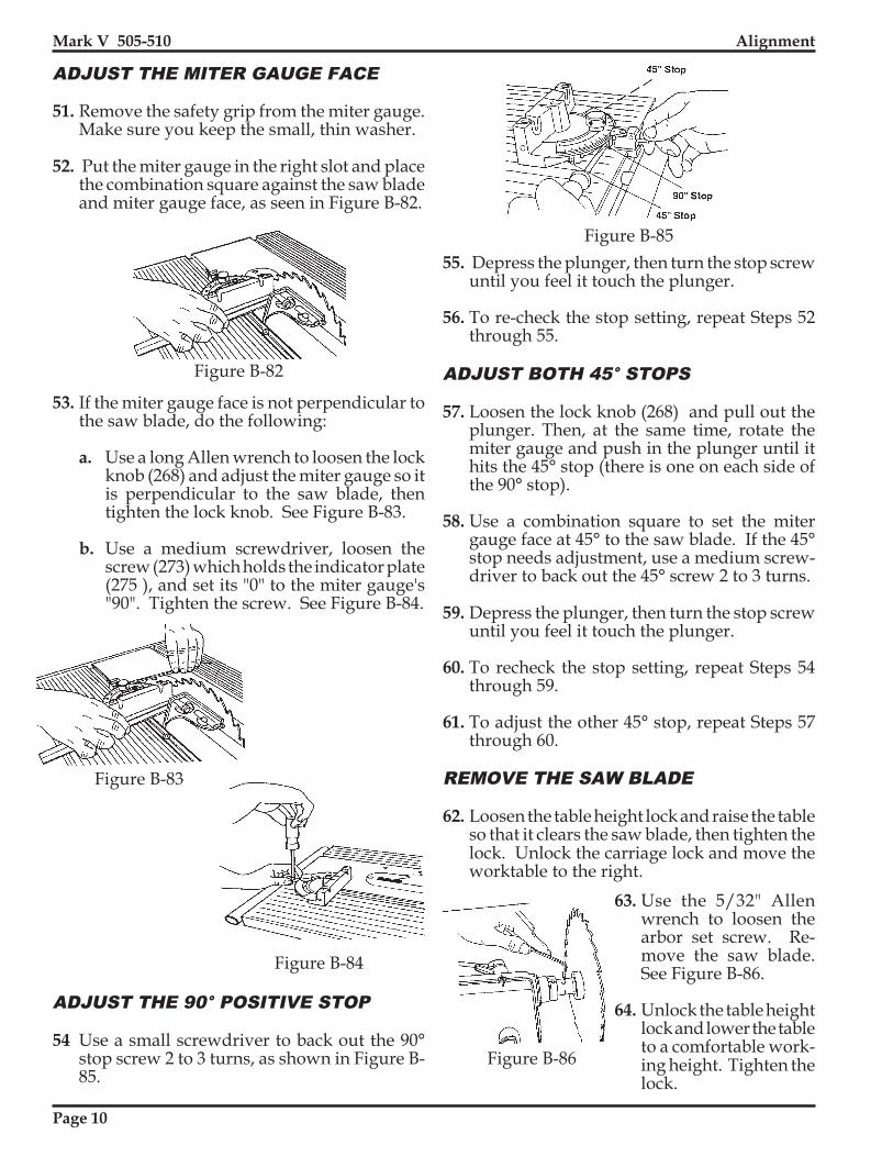
55. Depress the plunger, then turn the stop screwuntil you feel it touch the plunger.
56. To re-check the stop setting, repeat Steps 52through 55.
ADJUST BOTH 45° STOPS
57. Loosen the lock knob (268) and pull out theplunger. Then, at the same time, rotate themiter gauge and push in the plunger until ithits the 45° stop (there is one on each side ofthe 90° stop).
58. Use a combination square to set the mitergauge face at 45° to the saw blade. If the 45°stop needs adjustment, use a medium screw-driver to back out the 45° screw 2 to 3 turns.
59. Depress the plunger, then turn the stop screwuntil you feel it touch the plunger.
60. To recheck the stop setting, repeat Steps 54through 59.
61. To adjust the other 45° stop, repeat Steps 57through 60.
REMOVE THE SAW BLADE
62. Loosen the table height lock and raise the tableso that it clears the saw blade, then tighten thelock. Unlock the carriage lock and move theworktable to the right.
Figure B-85
Figure B-86
ADJUST THE 90° POSITIVE STOP
54 Use a small screwdriver to back out the 90°stop screw 2 to 3 turns, as shown in Figure B-85.
63. Use the 5/32" Allenwrench to loosen thearbor set screw. Re-move the saw blade.See Figure B-86.
64. Unlock the table heightlock and lower the tableto a comfortable work-ing height. Tighten thelock.

Page 11
Alignment Mark V 505-510
two screws attaching the fence rest. Tightenthe fence rest just enough to move it withfirm pressure. See Figure B-90.
ALIGN THE RIP FENCE
65. Place the rip fence on the worktable by firstputting the fence base on the front tube, asdemonstrated in Figure B-87, then loweringthe rest of the rip fence.
Figure B-87
Figure B-88
Figure B-89
Figure B-91
Figure B-90
OutfeedClamp
Fence Rest
Base Lock
Handle
66. Use a 5/32" Allen wrench to back out theadjusting set screw from the fence base so itdoesn't contact the infeed table tube, as shownin Figure B-88.
67. Check to see if the fence rest fully contacts theoutfeed table tube, as shown in Figure B-89.
68. If it doesn't, adjust the fence rest by doing thefollowing:
a. Raise the outfeed end of the rip fence anduse a medium screwdriver to loosen the
b. Place the rip fence back on the table andlock the handle.
c. Use your fingers to adjust the fence restuntil it fully contacts the outfeed tabletube.
d. Unlock the handle and carefully raise thefence. Use the medium screwdriver totighten the fence rest's screws.
e. Re-check the fence rest setting by remount-ing the rip fence on the worktable. If fur-ther adjustments are needed, repeat Stepsa through d.
ADJUST THE OUTFEED CLAMP
69. Place the rip fence base on the infeed tabletube, then lower the rip fence onto the outfeedtube. The outfeed clamp should just miss thetable tube as it is lowered into place.
70. Lock both the base lock and the handle. SeeFigure B-91.
71. If the clamp is too tight (hits the table tube), ortoo loose (allows slippage while it is locked),it needs adjusting. To adjust the outfeedclamp, do the following:
a. If too tight, raise the handle, then use a 1/2" socket and ratchet wrench to loosen the

Page 12
Mark V 505-510 Alignment
Figure B-93
Figure B-92
Figure B-94
Figure B-95
Figure B-96
lock nut (217). When the clamp touchesthe table tube, loosen the lock nut 1/8 turnor less. See Figure B-92.
b. If too loose, lock the handle, then use a 1/2" socket and ratchet wrench to tighten thelock nut (217). When the clamp touchesthe table tube, loosen the lock nut 1/8 turnor less. See Figure B-92.
ALIGN THE RIP FENCE PARALLEL
WITH THE WORKTABLE
72. Place the miter gauge in the left slot of theworktable on the infeed side, as shown inFigure B-93.
74. Move the rip fence toward the Allen wrenchuntil it just touches it, as in Figure B-95.
75. Lock the base knob and handle on the base tosecure both ends of the rip fence. See Figure B-95.
76. Slide the miter gauge back and forth in theslot. See Figure B-96. The tip of the Allenwrench should keep in slight contact with therip fence. Watch that you don't scratch thefence.
77. If it pulls away from or binds against the ripfence, the fence needs aligning. If so, do thefollowing:
a. Loosen the handle and base knob, removethe rip fence from the table and turn thefence upside down.
b. Use a medium Phillips screwdriver toloosen the two screws (225) near the fencebase, so they are just tight enough to re-quire firm pressure to align the fence. SeeFigure B-97.
73. Insert the long 5/32" Allen wrench throughthe miter gauge and secure it using the short5/32" Allen wrench and a set screw borrowedfrom the tool rest, as seen in Figure B-94.

Page 13
Alignment Mark V 505-510
c. Return the rip fence to the worktable.Slide it toward the Allen wrench until itcontacts the Allen wench at the infeedend.
d. Only tighten the base knob.
e. Slide the miter gauge back and forth,adjusting the fence until the Allenwrench makes consistent contact alongthe entire length of the rip fence. Again,remember to not scratch the fence.
f. When alignment is reached, lock thehandle. Slide the miter gauge back andforth along the fence to double checkthat the fence did not move when youlocked the handle.
g. Reach under the table and use the me-dium Phillips screwdriver to tightenthe screw closer to the base. See FigureB-98.
Figure B-97
Figure B-98
Figure B-99
h. Carefully unlock the handle and thebase knob on the base and lift the ripfence from the table.
i. Tighten the other adjustment screw.
j. To re-check the alignment, repeat Steps74 through 79g. (It is very important tore-check the alignment!)
ALIGN THE EXTENSION TABLE
NOTE
These instructions are for aligning the exten-sion table on the right side of the headstock.You can also follow these same procedures toalign it to the left side of the headstock.
For most projects, align the extension table onthe right side, since it can usually be used whenplaced on the left side. However, once the exten-sion table is aligned on the right side, it cannotbe transferred to the left side and still maintainprecise alignment.
If you wish precise alignment on the left side,repeat the following instructions– but place theextension table on the left side in the headstock.
78. Mount the extension table in the Mark V'saccessory base mount (on the right side) at acomfortable height, as shown in Figure B-99. Use a 1/2" wrench to loosen the bottomnuts holding the table base to the table ap-proximately 1/4" from the table. This willallow you room for later adjustment.
79. The worktable should already be mountedin the carriage mount. Move the worktablenext to the extension table and adjust it toabout 1/4" above the extension table, asseen in Figure B-100.
Page 14
Mark V 505-510 Alignment
80. Hold a straightedge against the infeed edgeof both the worktable and extension tabletubes, as in Figure B-101. Line up the exten-sion table's infeed edge with the worktable'sinfeed edge. The elongated holes in the ex-tension table's base permit you to slide theextension table forward and backward.
81. Hold a straightedge on the infeed top sur-face of both the worktable and the extensiontable, as shown in Figure B-102. As needed,adjust the top nuts located on the infeed sideof the extension table, in order for thestraightedge to be level across both the work-table and the extension table infeed sides.See Figure B-102a.
Figure 103a.
Figure B-102
Figure B-101
Figure B-100
Figure B-103
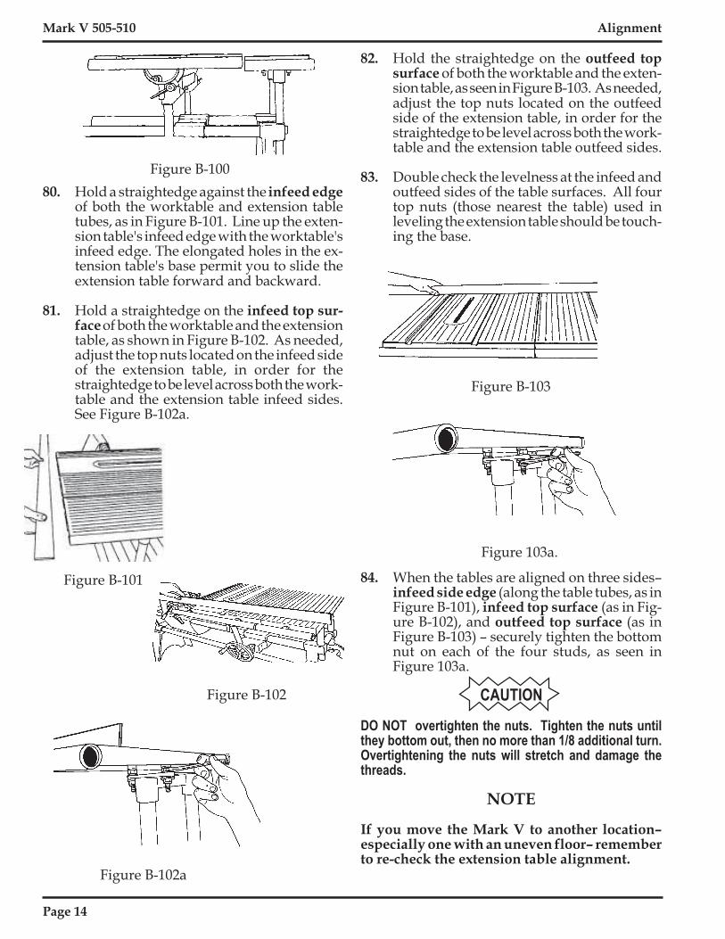
Figure B-102a
82. Hold the straightedge on the outfeed topsurface of both the worktable and the exten-sion table, as seen in Figure B-103. As needed,adjust the top nuts located on the outfeedside of the extension table, in order for thestraightedge to be level across both the work-table and the extension table outfeed sides.
83. Double check the levelness at the infeed andoutfeed sides of the table surfaces. All fourtop nuts (those nearest the table) used inleveling the extension table should be touch-ing the base.
84. When the tables are aligned on three sides–infeed side edge (along the table tubes, as inFigure B-101), infeed top surface (as in Fig-ure B-102), and outfeed top surface (as inFigure B-103) – securely tighten the bottomnut on each of the four studs, as seen inFigure 103a.
CAUTION
DO NOT overtighten the nuts. Tighten the nuts untilthey bottom out, then no more than 1/8 additional turn.Overtightening the nuts will stretch and damage thethreads.
NOTE
If you move the Mark V to another location–especially one with an uneven floor– rememberto re-check the extension table alignment.

Page 15
Alignment Mark V 505-510
Figure B-104
Figure B-108
Figure B-106
Keps Nuts
Figure B-105
Figure B-107
ALIGN THE EXTENSION
TABLE TUBES
85. Place the straightedge along the infeed-sidetops of both the worktable and extensiontable tubes, as shown in Figure B-104.
86. If the extension table's tube is not aligned withthe worktable's tube, use a 7/16" wrench toslightly loosen both keps nuts (248) attach-ing the tube to the extension table. Make theneeded adjustments, then re-tighten the nuts.See Figure B-105.
87. Repeat Steps 85 and 86 for the extensiontable's tube located on the outfeed-side.
MOUNT THE SAW GUARD
88. Loosen the accessory mount lock and removethe extension table. Loosen the table heightlock and remove the worktable. Place thesaw blade and arbor in the lower saw guardcover (204).
89. Fit the lower saw guard's clamp on the spindlequill (59). Line up the arbor set screw withthe spindle knob's set screw (where thespindle flat is located). Use a 5/32" Allenwrench to tighten the arbor set screw, asshown in Figure B-106.
90. Use the 5/32" Allen wrench to tighten thesocket head screw (215) on the saw guardcollar, as seen in Figure B-107.
INSTALL THE RIVING KNIFE
91. Loosen the guard lock knob (210) and insertthe upper saw guard's riving knife (199)between the guard (213) and the lock plate(208), as demonstrated in Figure B-108.

Page 16
Mark V 505-510 Alignment
Figure B-112
Figure B-111
Figure B-113
Figure B-114
Figure B-110
Figure B-109
92. Make sure the riving knife is fully seatedbetween the guard and the lock plate, as inFigure B-109. The curved portion of theriving knife should be very close to the sawblade teeth (about 1/8"), as illustrated inFigure B-110. Tighten the guard lock knob(210). Look to see if the riving knife iscentered with the saw blade, as shown inFigure B-111.
93. If the riving knife is not centered with thesaw blade, follow these steps:
a. Notice which way the riving knife is notcentered with the saw blade.
b. Unclamp and remove the upper saw guard,then remove the saw blade and lower sawguard.
c. Use a 5/32" Allen wrench to adjust the stopscrew (211) located below the lower sawguard's collar, as seen in Figure B-112.
� If the riving knife is to the left of thesaw blade, back out the stop screw(counter-clockwise).
� If the riving knife is to the right ofthe saw blade, screw in the stop screw(clockwise).
d. Re-install the saw blade, lower saw guardand riving knife, according to Steps 88through 92. If the riving knife is still notcentered on the saw blade, repeat this Step93.

Page 17
Alignment Mark V 505-510
Figure B-118
Figure B-117
Figure B-116
Figure B-115
ALIGN THE LATHE CENTERS
94. Remove the saw guards and the saw blade,then loosen the carriage and headstock locks.Move the headstock and carriage all the wayto the right and lock them in place.
95. Mount the drill chuck on the spindle, asshown in Figure B-113. Completely closethe chuck jaws, as in Figure B-114.
96. Mount the cup center into the tailstock'sadjustable center, as seen in Figure B-115,then mount the tailstock into the base mount(right side). Tighten the mount lock.
97. Loosen the quill lock. Extend the quill (seenin Figure B-116), so the drill chuck almosttouches the cup center point and the centerpoint could fit into the chuck jaws.
98. If the center point does not "fit" into thechuck jaws, determine whether you need toadjust the cup center point horizontally and/or vertically. Then do the following:
a. To adjust the cup center point horizon-tally, loosen the set screw that locks theadjustable center, as seen in Figure B-117.Rotate the adjustable center as needed toline up the cup center with the drill chuck,then tighten the set screw.
b. To adjust the cup center point verti-cally, loosen the mount lock, then loosen thetailstock stop collars. Raise or lower thetailstock in the base mount until the cupcenter point vertically lines up with the drillchuck, then tighten the mount lock. Pressthe stop collars down firmly against the basemount and tighten the collar set screws, asshown in Figure B-118.