Embed Size (px)
Citation preview
1
ALIGNMENT DOWEL DESIGN GUIDELINES

Doweling for Permanent Positioning
If components are located or positioned by methods otherthan the doweling itself, and the issue is to allow fordisassembly and then re-assembly with the componentsin exactly the same location – then it is recommended thatthe components be drilled together and the dowel installedin the assembled condition. During disassembly, the dowelmay be removed and reinstalled during re-assembly. Thismethod eliminates the need for hole tolerancing and holecenterline concerns. It provides for very accuratepermanent locating.
DESIGN GUIDELINES
Doweling to Fix Relative Location Of Components
The more common application is to use the dowels to fix the relative location of two or more components. In this situation,the dowels are partially installed in one component, the initial installation, and then holes in the mating component arepushed over the exposed end of the partially installed dowel. The following factors need to be considered for precisionlocation:
� Hole dimension tolerance
� Relative depth of initial installation
� Total length of the bushing
� True position of hole centerlines
These factors are interrelated and need to be considered together. The following general guidelines are helpful indetermining the best design in a specific situation.
� Precise holes with reduced hole tolerances increase the cost but also increaselocation accuracy and simplify the design considerations.
� Wider hole tolerances require longer dowels to assure a tight, non clearance fit inboth components.
� Hole tolerance should be minus in the initial installation hole and plus in the matingcomponent hole.
� The maximum hole tolerance should not exceed one half (1/2) of the recommendedtolerance range to allow for hole tolerancing of both holes within the tolerance range.
� Fixing the dowel location in a through hole can be achieved through length ofengagement and hole tolerancing, or both. Generally, an engagement of 60% ofthe total length in the smaller hole is recommended for the fixed location.
� If more than one dowel is used, holes in the upper recommended tolerance rangeallow for a wider tolerance in centerline location.
DESIGN GUIDELINES
Precise Holes
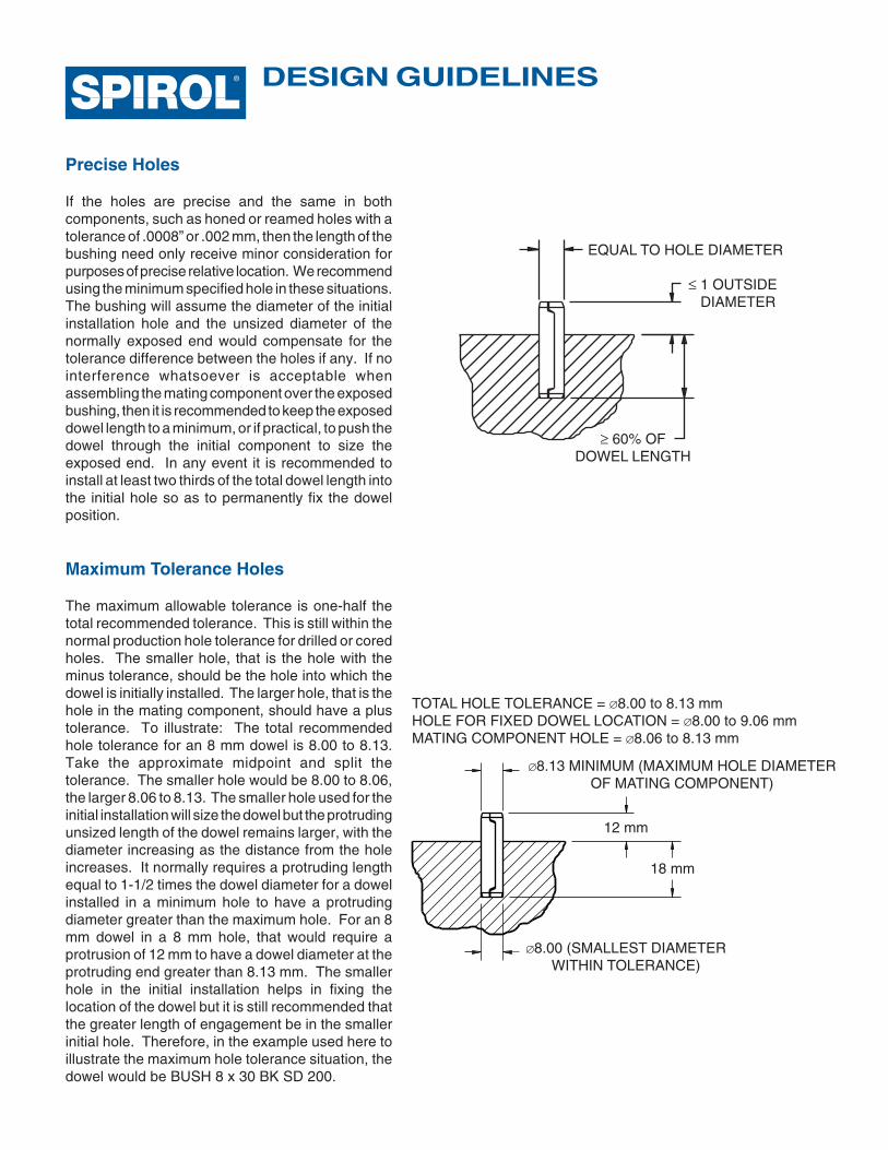
If the holes are precise and the same in bothcomponents, such as honed or reamed holes with atolerance of .0008” or .002 mm, then the length of thebushing need only receive minor consideration forpurposes of precise relative location. We recommendusing the minimum specified hole in these situations.The bushing will assume the diameter of the initialinstallation hole and the unsized diameter of thenormally exposed end would compensate for thetolerance difference between the holes if any. If nointerference whatsoever is acceptable whenassembling the mating component over the exposedbushing, then it is recommended to keep the exposeddowel length to a minimum, or if practical, to push thedowel through the initial component to size theexposed end. In any event it is recommended toinstall at least two thirds of the total dowel length intothe initial hole so as to permanently fix the dowelposition.
Maximum Tolerance Holes
The maximum allowable tolerance is one-half thetotal recommended tolerance. This is still within thenormal production hole tolerance for drilled or coredholes. The smaller hole, that is the hole with theminus tolerance, should be the hole into which thedowel is initially installed. The larger hole, that is thehole in the mating component, should have a plustolerance. To illustrate: The total recommendedhole tolerance for an 8 mm dowel is 8.00 to 8.13.Take the approximate midpoint and split thetolerance. The smaller hole would be 8.00 to 8.06,the larger 8.06 to 8.13. The smaller hole used for theinitial installation will size the dowel but the protrudingunsized length of the dowel remains larger, with thediameter increasing as the distance from the holeincreases. It normally requires a protruding lengthequal to 1-1/2 times the dowel diameter for a dowelinstalled in a minimum hole to have a protrudingdiameter greater than the maximum hole. For an 8mm dowel in a 8 mm hole, that would require aprotrusion of 12 mm to have a dowel diameter at theprotruding end greater than 8.13 mm. The smallerhole in the initial installation helps in fixing thelocation of the dowel but it is still recommended thatthe greater length of engagement be in the smallerinitial hole. Therefore, in the example used here toillustrate the maximum hole tolerance situation, thedowel would be BUSH 8 x 30 BK SD 200.
EQUAL TO HOLE DIAMETER
≤ 1 OUTSIDE DIAMETER
≥ 60% OFDOWEL LENGTH
TOTAL HOLE TOLERANCE = ∅8.00 to 8.13 mmHOLE FOR FIXED DOWEL LOCATION = ∅8.00 to 9.06 mmMATING COMPONENT HOLE = ∅8.06 to 8.13 mm
∅8.13 MINIMUM (MAXIMUM HOLE DIAMETEROF MATING COMPONENT)
12 mm
18 mm
∅8.00 (SMALLEST DIAMETERWITHIN TOLERANCE)
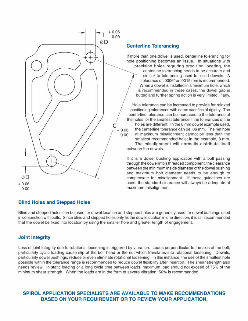
Centerline Tolerancing
If more than one dowel is used, centerline tolerancing forhole positioning becomes an issue. In situations with
precision holes requiring precision locating, thecenterline tolerancing needs to be accurate andsimilar to tolerancing used for solid dowels. A
tolerance of .0006” or .0015 mm is recommended.When a dowel is installed in a minimum hole, which
is recommended in these cases, the dowel gap isbutted and further spring action is very limited, if any.
Hole tolerance can be increased to provide for relaxedpositioning tolerances with some sacrifice of rigidity. The
centerline tolerance can be increased to the tolerance ofthe holes, or the smallest tolerance if the tolerances of the
holes are different. In the 8 mm dowel example used,the centerline tolerance can be .06 mm. The net holeat maximum misalignment cannot be less than thesmallest recommended hole; in the example, 8 mm.The misalignment will normally distribute itself
between the dowels.
If it is a dowel bushing application with a bolt passingthrough the dowel into a threaded component, the clearancebetween the minimum inside diameter of the dowel bushingand maximum bolt diameter needs to be enough tocompensate for misalignment. If these guidelines areused, the standard clearance will always be adequate atmaximum misalignment.
SPIROL APPLICATION SPECIALISTS ARE AVAILABLE TO MAKE RECOMMENDATIONSBASED ON YOUR REQUIREMENT OR TO REVIEW YOUR APPLICATION.
Blind Holes and Stepped Holes
Blind and stepped holes can be used for dowel location and stepped holes are generally used for dowel bushings usedin conjunction with bolts. Since blind and stepped holes only fix the dowel location in one direction, it is still recommendedthat the dowel be fixed into location by using the smaller hole and greater length of engagement.
Joint Integrity
Loss of joint integrity due to rotational loosening is triggered by vibration. Loads perpendicular to the axis of the bolt,particularly cyclic loading cause slip at the bolt head or the nut which translates into rotational loosening. Dowels,particularly dowel bushings, reduce or even eliminate rotational loosening. In this instance, the use of the smallest holepossible within the tolerance range is recommended to reduce dowel flexibility after insertion. The shear strength alsoneeds review. In static loading or a long cycle time between loads, maximum load should not exceed of 75% of theminimum shear strength. When the loads are in the form of severe vibration, 50% is recommended.
+ 0.06– 0.00
+ 0.06– 0.00
+ 0.06– 0.00
∅ D
∅ D
C
© 2009 Spirol International Corporation 05/09
e-mail: [email protected]
Canada
Mexico
Europe
U.S.A. Spirol International Corporation30 Rock AvenueDanielson, Connecticut 06239Tel. 860.774.8571 Fax 860.774.2048
Spirol West Inc.1950 Compton Avenue, Unit 111Corona, California 92881-6471Tel. 951.273.5900 Fax 951.273.5907
Spirol International Corporation Shim Division321 Remington RoadStow, Ohio 44224Tel. 330.920.3655 Fax 330.920.3659
Spirol Distribution30 Rock AvenueDanielson, Connecticut 06239Tel. 800.321.4679 Fax 860.774.0487(For Distributor Customers)
Spirol Industries, Ltd.3103 St. Etienne BoulevardWindsor, OntarioCanada N8W 5B1Tel. 519.974.3334 Fax 519.974.6550
Spirol México, S.A. de C.V.Carretera a Laredo KM 16.5 Interior ECol. Moisés SaenzApodaca, N.L. 66613 Méxicoó Apdo. Postal 151 de Apodaca, N.L.Tel. (81) 8385 4390 Fax (81) 8385 4391
Spirol Industries, Ltd.Princewood RoadCorby, NorthantsEngland NN17 4ETTel. 44 (0) 1536 444800Fax 44 (0) 1536 203415(For Distributor Customers)Tel. 44 (0) 8003 890034
Spirol SASRue Henri Rol TanguyZ.A. Les Naux51450 BéthenyFranceTel. 33 (0)3 26 36 31 42 Fax 33 (0)3 26 09 19 76
Spirol GmbHBrienner Strasse 980333 MunichGermanyTel. 49 (0) 931 454 670 74Fax. 49 (0) 931 454 670 75
Spirol International EngineeredFastener Trading Co. Ltd.No. 11 Xi Ya Rd. NorthSection A, 1F, Building 14Wai Gao Qiao Free Trade ZoneShanghai, China 200131Tel. (8621) 5046 1451/1452Fax (8621) 5046 1540
Asia Pacific
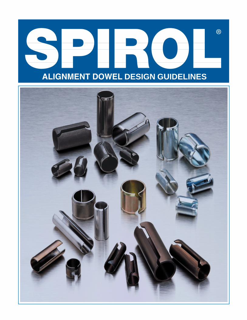
Alignment Dowels
Application:
Alignment for Clutch Plate in Heavy Equipment
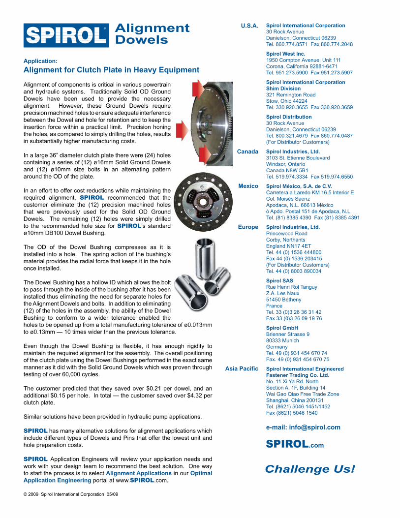
Alignment of components is critical in various powertrain and hydraulic systems. Traditionally Solid OD Ground Dowels have been used to provide the necessary alignment. However, these Ground Dowels require precision machined holes to ensure adequate interference between the Dowel and hole for retention and to keep the insertion force within a practical limit. Precision honing the holes, as compared to simply drilling the holes, results in substantially higher manufacturing costs.
In a large 36” diameter clutch plate there were (24) holes containing a series of (12) ø16mm Solid Ground Dowels and (12) ø10mm size bolts in an alternating pattern around the OD of the plate.
In an effort to offer cost reductions while maintaining the required alignment, SPIROL recommended that the customer eliminate the (12) precision machined holes that were previously used for the Solid OD Ground Dowels. The remaining (12) holes were simply drilled to the recommended hole size for SPIROL’s standard ø10mm DB100 Dowel Bushing.
The OD of the Dowel Bushing compresses as it is installed into a hole. The spring action of the bushing’s material provides the radial force that keeps it in the hole once installed.
The Dowel Bushing has a hollow ID which allows the bolt to pass through the inside of the bushing after it has been installed thus eliminating the need for separate holes for the Alignment Dowels and bolts. In addition to eliminating (12) of the holes in the assembly, the ability of the Dowel Bushing to conform to a wider tolerance enabled the holes to be opened up from a total manufacturing tolerance of ø0.013mm to ø0.13mm — 10 times wider than the previous tolerance.
Even though the Dowel Bushing is flexible, it has enough rigidity to maintain the required alignment for the assembly. The overall positioning of the clutch plate using the Dowel Bushings performed in the exact same manner as it did with the Solid Ground Dowels which was proven through testing of over 60,000 cycles.
The customer predicted that they saved over $0.21 per dowel, and an additional $0.15 per hole. In total — the customer saved over $4.32 per clutch plate.
Similar solutions have been provided in hydraulic pump applications.
SPIROL has many alternative solutions for alignment applications which include different types of Dowels and Pins that offer the lowest unit and hole preparation costs.
SPIROL Application Engineers will review your application needs and work with your design team to recommend the best solution. One way to start the process is to select Alignment Applications in our Optimal Application Engineering portal at www.SPIROL.com.