Embed Size (px)
DESCRIPTION
Â
Citation preview

ABPL30048SEMESTER 1 2015
MIKAELA PRENTICE 636 455
ADS | AIR

4 INTRODUCTION
PART A: CONCEPTUALISATION8 A1. Design Futuring10 A2. Design Computation12 A3. Composition/Generation14 A4. Conclusion15 A5. Learning Outcomes16 A6. Appendix Algorithmic Sketchbook
21 REFERENCES
PART B: CRITERIA DESIGN24 B1. RESEARCH FIELD26 B2.. CASE STUDY 0128 Matrix of iterations30 Analysis of results32 B3. Case study 0234 Producing algorithm36 b4. technique development40 Analysis of Results42 b5. Prototyping46 b6. proposal
Not my image: will replace before submissionHouse in Bruges Unbuilt (2010), Lisa Iwamoto, http://www.dwell.com/house-tours/slideshow/cut-it-out-work-lisa-iwamoto#6
contents

I am currently studying in my third year of a Bachelor of Environments degree, majoring in architecture.
I have been interested into the design and building field since I can remember. Mum and Dad love to decorate and renovate so I think I got my first taste of this career path from them.
Going into the Bachelor of Environments, I was 70% sure I would follow architecture, however I wasn’t sure I would be creative enough. After my first taste of design through the class ‘Designing Environments’, I really began to believe in myself as an ‘architect’.
Throughout my time at university, I have developed a strong passion for architecture and am continually inspired by what developments are occuring in the industry at the moment. I am very excited to explore computational design through Grasshopper, as I believe that it will be the way of the future for architectural practice and design.
Previous studio experience is limited to completing the Architectural Design Studio: Water in Semester 2, 2014. In this studio we were guided to explore the concepts and techniques of a master architect, ours being Alvar Aalto. Through exploration of Aalto’s famous works, we studied his principles, which we were then to apply to our own project, the Boathouse redevelopment at Studley Park in Kew. In this studio I used the following digital programs:
SketchUp - To map and phsyically represent the site using the topographically information given. I was then able to convert this and import into AutoCad in orer to develop floor plans suited to the landscape.
AutoCad - To draft floor plans and site plans with proper architectural conventions.
Rhino 3D - To develop a three dimensional model of the site and of the proposed boathouse. Making an accurate 3D model allowed me to explore the spatial and formal arrangements of the design in real scale.
Vray - To input materiality to the 3D model, and the create realistic renders of the model and the site.
Adobe Photoshop - To further develop realistic renders for presentation.
Adobe Indesign - To layout the final presentation.
The final renders of my design can be seen on the opposite page.
INTRODUCTION
Mikaela Prenticeuniversity of melbourne bachelor of environments third year architecture
4 INTRODUCTION

6 CONCEPTUALISATION CONCEPTUALISATION 7
PART [A] CONCEPTUALISATION

A [one]
ONE CENTRAL PARK Jean Nouvel
Landscape is architecture. So at One Central Park, we have created a kind of continuity between the park and the buildings, so the facades literally extend the park to the sky. By miming what can exist in Australian nature, we are proposing a new form of highrise living in direct contact with nature.
Jean Nouvel
One Central Park, Central Park, http://www.centralparksydney.m/live/one-central-park/architecture-and-design
Design Futuring
DONGDAEMUN DESIGN PLAZA Zaha HadidDongdaemun Design Plaza, http://www.zaha-hadid.com/architecture/dongdaemun-design-park-plaza/
“
“
-
....A FIELD OF PIXILATION AND
PERFORATION PATTERNS....
THE DESIGN INTEGRATES THE PARK AND PLAZA SEAMLESSLY AS
ONE, BLURRING THE BOUNDARY BETWEEN
ARCHITECTURE AND NATURE IN
A CONTINUOUS, FLUID LANDSCAPE.
ZAHA HADID ARCHITECTS
“
“
-
In a sustainable context, the green wall provides a message of sustainability. The plants absorb carbon dioxide, not only cooling the interior of the building, and creating a more pleasant environment for its inhabitants, but also cooling its immediate surroundings. This helps to alleviate the detrimental heat island effect present in all urban environments.
Construction of One Central Park was completed in 2013. Now, a year and a half on, the success of the project is undeniable. As the building has been a fully functional and lived in complex for over a year now, the heliostats have been able to complete more than a full cycle of the seasons. I believe the realisation of this sustainable strategy, and the praise it has received, will become revolutionary. It will encourage all practitioners in the building and development field to rethink the way they approach sustainable services.
A statement from Ateliers Jean Nouvel sums it up best in saying that “parks and gardens have at all times been the most desirable places to live next to”1 (because vegetation signals life. It is this innate human desire that will drive future residential development towards a similar method of practice.
One Central Park can be seen as a beacon in the exploration of emerging sustainable technologies at a high-density urban scale. From having the tallest vertical garden in the world, to being the first residential building in the world to experiment with sunlight harvesting and redirecting applications, One Central Park will stand as an inspiration for projects of all scales to come.
One Central Park is the outcome of the redevelopment of the old Carlton and United Brewery site. One of the ‘design challenges’ of the project was how to incorporate a new park at an appropriate urban scale. Aesthetically, the creation of a ‘living green facade’ gives residents pleasing private gardens on their balconies, and at a collective scale, provides the city with a green urban sculpture. Basically, One Central Park acts as a forest in the sky. In this instant, the development proposes a solution to the problem of an ever increasing concrete jungle. Imagine a future where most urban buildings were covered in plants… we would inhabit a city that acted like a forest. Fostering the most pleasant of natural processes and creating a place for all living things to thrive. .
apparent, in that the entire project is a work of collaboration and combination, not just in design process, but in design outcome, and how the building will function in the future. This is seen in a number of ways:
The design allows the architecture, the city and land to combine in both form and spatial awareness.It blurs the relationship between interior and exterior (which is a factor that will continually develop in the near future)It meets the needs of a variety of people and can function in any number of ways due to the fluid nature of the interior and exterior spaces. And, the DDP is an amalgamation of the past, the present and the future. It acts as a link between the city's contemporary culture, emerging nature and rich history.
It is also important to note that whilst not a pioneer in its use of BIM technologies, the success in which it uses BIM for construction management and engineering coordination should be celebrated. Its success meant that the design was fluidly adapting with the evolving brief and interaction between the varying stakeholders. BIM software is an important element of collaborative workflow.
Zaha Hadid's Dongdaemun Design Plaza in Soeul, Korea is a prime example of a design engaging with the community for whom they are designing. Tony Fry declared that designers need to "broaden [their[ gaze… stop talking to yourselves.. And start talking to other people, other disciplines." The DDP was built to be a cultural hub in the centre of Soeul, for people of all ages and all backgrounds. Instead of the architect embarking on a prescribed design journey based on the given brief, Zaha Hadid Architects instead go against the norm and continually engage the people who will be the users of the site. The DDP, as a design project, and as a completed complex, "engages the community in a collective dialogue where many contributions and innovations feed into each other, allowing talents and ideas to flourish"2.
This concept, of community engagement and interaction, is a way of thinking that transcends traditional architectural practice, and as such, can be seen as a radical process which delivers a product and an experience unlike before.
The design process of Zaha Hadid Architects will surely be emulated the world over, as the success of the collaborative approach is
8 DESIGN FUTURING
[[[[[1GA Document. 2014. GA Document 129 (Toyko: GA. Futagawa, 28-342GA Document, 2014, 40-48

Currently, with the continuous development of Computer Aided Design programs, such as Grasshopper, Architects are reverting back to a pre-Renaissance state, in which they are considered the ‘Master Builder’1. No longer are architects involved in just designing the form of a building, instead, architects become the engineers, the craftsman, the material designer and the surveyor. This is all with thanks to the development of computational design technologies.
Computing is now involved in all stages of the design process. We can now begin generating form in CAD programs whilst inputting data which constrains the possibilities of the design. Inputting data allows the architect to analyse the performative aspect of a design in real time. The data can include anything from weather, material capabilities, sun pattern, wind flow, to human traffic data. Without the use of a computational system, an architect would have to have the knowledge to interpret the data correctly, and then manually refine the design with these in mind. However now, in a program such as Grasshopper, the design can adapt and mould itself based on this data. The benefits of this reach much further than making architectural practice faster and more efficient. Rivka and Robert Oxman (2014: 6) stated that the morphogenesis capacity of computational programs means that we have the capability to produce a ‘second nature’, meaning we take the knowledge and the principles learned in nature and apply it to the buildings, so that the built environment and the natural environment mimic each other, ensuring that we lived in a harmonious and sustainable environment.
Computational techniques are also allowing architects to experiment with tectonic design and material manipulation. By inputting material capability data, in conjunction with other parameters such as sun angles, the architect is able to re-design or reconfigure the material so that it is functioning to its maximum capacity within the environmental context2.
A [two] Design computation
ICD ITKE RESEARCH PAVILION, 2010
Research Pavillion Diagrams, http://detail-online.com/inspiration/research-pavilion-in-stuttgart-106075.html
ICD Research Pavillion, http://www.achimmenges.net/wp-content/gallery/arch[icd[researchpavilion/webam[arch[10[icd[researchpavilion[am[tn07.jpg
This research project explored the natural material properties of thin boards of plywood, inputting the data into a computational system and deriving an outcome that is based on the bending deformation of the wood within the elastic range.
This project shows how design computation is allowing architects to go beyond the realm of just using a material, instead enabling them to redefine the material .within the designed context.
Design computation was used throughout the entire process, from research, to inception, to material production, engineering simulation and robotic manufacturing1.
DIFFERENTIATED WOOD LATTICE STUDIO, 2009
This project was undertaken as part of the Performative Wood Studio at the Harvard University Graudate School of Design in 2009, The structure was derived from detailed studies on the actuation force, the size, thickness and fibre orientation, and required torque. They developed their own computational tool for assessing the aforementioned factors, which they used to generate this full scale prototype.
Huang and Park went one step further and used computational fabrication techniques to bring the prototype to life. A robotic water-jet cutting application was used so as the integrity of the wood was not compromised during production.
The structure relies on a lattice skin, whose actators are adjusted accoring to the computationally derived outcomes. The skin is attached the the wooden planar grid system, and causes the lattice to rise into its “computationally derfined, structurally stable double-curved form2.
Achim Menges 2012 architectural design - material resource fullness (Image),34 - 43
10 DESIGN COMPUTATION
1Oxman, R., and R. Oxman. 2014. 'Introduction: Vitruvius Digitalis', in Anonymous Theories of the Digital in Architecture (London; New York: Routledge), 5
2 Oxman, R., and R. Oxman. 2014, pp. 1-103Menges.A, 2102. ‘Material Resourcefullness.’ Architectural Design: 34-43

Messe Bassel Exhibition Centre, Herzog & De Meuron, Using computational techniques to create a ‘basketweaved’ effect of three new towers at the Messe Bassel Centre.3
http://www.dezeen.com/2013/08/08/flinders-street-station-by-herzog-de-meuron-hassell/
The winning Flinders Street Station competition design collaboration between Herzog & De Meuron and HASSELL used computational design techniques and performative design parameters to generate the arching forms of the proposed railway.
In recent years, the shift from composition to generation using computational technologies has greatly impacted the architectural design process, and as a consequence, the way architecture is practiced. Now, digital tools not only create opportunities in design process, fabrication and construction, but also in the generation and formation of design concepts1.
Firms such as Herzog & De Meuron are leading the way in this field, by investing in a dedicated “Technology” team at their head office. Rather than using the technology avaliable, the team actually finds and develops their own tool in response to the particular design brief. They often use scripting, but also use tools such as BIM software. Strehlke, the lead of the techology group, says that ‘performance’ is their main driver, whilst reiterating that architecture and its intent remains paramount.
‘The focus is,first of all, only on the architecture. So whenwe use methods of computation, it is not a
technology that we try to do something withit; the focus is more on design intent and thearchitectural idea and concept. We try to find
the right tool, and develop the tool to make the concept work.2’
The above statement shows that whilst design intent remains at the forefront of their minds, the computational response to this intention is what generates and conceives the ‘built’ response.
The generation of a design response based on performance critera is what sets computationally oriented firms and traditional firms apart. It is not through desire or intent that the geometrical forms of their designs are develeoped, instead they are a direct response to the performative demands of the building, from conception. Before the inception of performative based script technology, such as Grasshopper and its various entities, a designer would receive a package of hundreds of pages of the engineers or environmental specialists, and have to manually edit to influence the design directly.
In this case, I believe Herzog & De Meuron have maintained a practice which is equally funded on design and technology. They are responding to the brief as traditional architects in a ‘conceptual’ approach, however this approach is generated by computation scripting and performative modelling techniques.
Using only computational techniques to generate a design response can be risky, as it eliminates any sense of ‘aesthetic’ control of the architect. However, the way Herzog & De Meuron have developed their process of design seems to combat this loss of control2
A [three] COmposition/Generation
12 COMPOSITON/GENERATION
HERZOG & DE MEURON
1Peters, B. 2013. ‘Computation Works: The Building of Algorithmic Thought’, Architectural Design, 83: 8-15.
2Peters, B. 2013. 'Realising the Architectural Idea: Computational Design at Herszog & De Meuron', Architectural Design Journal: 60
3Peters, B. 2013, ‘Realising the Architectural Idea’, 56-614soma. 2012. Theme Pavilion (http://www.soma-architecture.com/index.
php?page=theme[pavilion&parent=2: soma Architecture)5soma. 2012
6ArchDaily. 2012. One Ocean, Thematic Pavilion EXPO 2012 (<http://www.archdaily.com/?p=236979>: ArchDaily)
7Knippers, J. 2013. ‘From Model Thinking to Process Design’, Architectural Design, 83: 74-81
SOMA ARCHITECTS
soma is an Australian architectural firm who define architecture as “thinking in concepts”4. The team are award winning in their development of contemporary digital design strategies, as can be seen in the below example.
The One Ocean, Thematic Pavillion designed and built for permanent exhibition at the EXPO 2012, was designed to reflect how we interpret and experience the ocean: as and endless surface, and as depth. It is this duality that inspired the building’s spatial and organisational concept5.
However, it is the facade system which truly encompasses the firms intention of computational design inspiring generation. The facade is made up of glass fiber reinforced polymers that can be morphed into a number of animated patterns based on research that investigated how biological moving mechanisms can be applied at a built architectural level6. The louvres of the facade are seen to morph based on the pattern of the sun (as seen to the left)7.
It is through this exploration of biomimetic research and data that the facade system was developed, hence dictating the overall form of the building and the aesthetic appreciations.
It is my understanding that soma’s form generating came solely from the research and data inputted into computational design systems. In this instance, with the focus of the EXPO being ‘The Living Ocean and Coast’, I believe this generating technique has been extremely successful. Using biomimicry to generate form could be a disadvantage if the brief was very limited in its scope, or if it demanded a specific ‘aesthetic’ appearance, as that may be hard to achieve using these principles.

Through exploration and research of the prevelance of digital and computational design technologies, it is clear that the landscape in which we practice architecture is changing.
We have a need to respond to the changing world around us, and combat defutur-ing with innovative and unique techniques, as seen in part A One. The projects referenced will serve as inspiration for my coming design, not only for the aes-thetic qualities they have, but in the design techniques they created and applied.
It is therefore also important to not think like a ‘traditional’ architecture, whereby you design the program and the aesthetics of the building based on what they dictate to be a response to the brief. Nowadays, the architect takes on a role akin to a ‘mas-ter builder’. It is nolonger sufficient to design a building using regular methods and ma-terials. As seen in A Two, with the emergence of highly sophisticated digital design technologies, we as architects are able to manipulate materials, create our own ma-terials, develop software to dictate facade treatments or develop continuous itera-tions based upon performative data running alongside changes in our modelled design.
Computational design has allowed architecture to become a col-laborative process amongst all practioners within the industry.
Finally, it was through research in A Three that I really found inspiration. The de-velopment of software indivudal to a specific brief, as at Herzog & De Meuron will be too complex to tackle in the short space of generative time we have, how-ever I will take inspiration from the way they treat every task indivudally, and use computational design to enhance the architecture, not to take over from it.
I am also interested in exploring the biomimetic principles outlined in soma’s research. The way their designs react to their landscape, whilst fitting it with it, is something I am keen to explore.
I believe it is significantly important to design in a way that uses technology and com-putational design to influence and enhance architecture as a way of bettering the future.
It is not just architects and the building and design industry who will benefit from computational design. Infact one building could have a widespread impact, from the inhabitants of the building, to its neighbors, to the wider community, and also to the general health and wellbeing of our planet.
I came into this subject knowing that it would be extremely beneficial, not only for enhancing my tehcnical profficiency at computer aided drawing programs, but also for my knowledge of the changing landscape of architectural design,
Learning about computational design has inspired me in a way I didn’t think possible. Naively, I had previously considered architecture in a tightly constrained box, seperate from the other disciplines of the industry. However, now, I have a greater understanding and appreciation for the colloborative effect of architecture, particularly in response to computational technology.
Learning the varying capabilities and capacities of computational de-sign has been beneficial for future development and study. From generating forms through performative data input, to generating and creating a new mate-rial based on the inherent capacity of old materials, the possibilites are endless.
Now, looking back on previous studios work, such as Water Studio , shown on page 5, there were so many ways I could have developed the design futher. One of my main drivers for the design was the angle of the topography and how I can use that to merge my design with the river. Knowing more about computational design tools now, I realise that I could have collected data from the site and used that to inform, generate and develop the response.
A [four] conclusion A [five] learningoutcomes
14 CONCLUSION LEARNING OUTCOMES 15

A [six] algorithmicsketchbook
14 ALGORITHMIC SKETCHBOOK16 ALGORITHMIC SKETCHBOOK

18 CONCEPTUALISATION

referencesArchDaily. 2012. One Ocean, Thematic Pavilion EXPO 2012 (<http://www.archdaily.com/?p=236979>: ArchDaily)
Fleischmann et al. 2012. 'Material Behaviour', Architectural Design: 43-54
GA Document. 2014. GA Document 129 (Toyko: GA. Futagawa)
Knippers, J. 2013. 'From Model Thinking to Process Design', Architectural Design, 83: 74-81
Menges, A. 2012. 'Material Resourcefullness', Architectural Design: 34-43
Oxman, R., and R. Oxman. 2014. 'Introduction: Vitruvius Digitalis', in Anonymous Theories of the Digital in Architecture (London; New York: Routledge), pp. 1-10
Peters, B. 2013. 'Computation Works: The Building of Algorithmic Thought', Architectural Design, 83: 8-15
---2013. 'Realising the Architectural Idea: Computational Design at Herszog & De Meuron', Architectural Design Journal: 56-61
soma. 2012. Theme Pavilion (http://www.soma-architecture.com/index.php?page=theme[pavilion&parent=2: soma Architecture)
REFERENCES 21

PART [B] CRITERIA DESIGN

B [ONE] RESEARCH FIELD
24 RESEARCH FIELDS
strips and foldingStrips and Folding is the algorithmic technique in which a single surface is transformed into a volume. It is a ‘succesion of transformation’ in which the continuity of the material is emphasised.
Deleuze, an architectural historian, discusses the importance of folding in Baroque architecture. He states that folding is an endlessly producing operative1. Deleuze continues to discuss the elements of folding techniques including points of inflection, elastic points and transformations, which were such important elements of Baroque mathematics. It is interesting here, to notice to correlation between historical architecture usage of such techniques, and the usage and adaptation of these techniques in the digital age. Deleuze also implies that a fold has neither a beginning or an end point.
Thankfully, in the computational age, the manipulation and application of these techniques are much easy and more widely avaliable thank in the 18th and 19th centuries.
In altering the frequencies of the folds, one can alter the volumetric spaces both internally and externally. The surfaces of these volumes are also changed by adding or removing folds, i.e. folding or unfolding.
There are many different techniques for organising folds. These can be parallel, intersecting or overlapping. Each technique changes the visual aesthetic and the spatial experience of a shape.
In terms of fabrication, the strips and folding technique is economical, in that is reduces waste by utilising as little material as possible.
Practical application of this technique sees facades created purely of folded strips, which as a method of design, becomes the structure itself, meaning less need for material. This application is both financially and timely economical.
Strips and folding has an inherent complexity in which the fluid lines express speed and dynamism. This is further enhanced through the functions of light and shadow. The complexity of this can be increased by increasing the number of strips. This increases density, blurring the image, furthering the sense of speed and velocity.
Loop[3 Project, Co-de-It, http://www.co-de-it.com/wordpress/loop[3.html
L O O P 3co-de-it
- Strips form the curvature of the form.- Strips form loops at all 3 projecting wings- Horizontal and vertical elements inside created a stable structural sequence- Use of timber, pliability, moldable.- Pin joints, allow for rotation- Has a sense of fluidity and movement through the use of continuous planes of strips- Ripple effect- Trigonometric functions to derive curves2
1Deleuze, G. 1933. ‘The Fold: Leibniz and The Baroque’: 1-62 Erioli, A. 2012. Loop[3 (http://www.co-de-it.com/wordpress/loop[3.html)3Grozdanic , L. 2012. Archipelago Parametrically Designed Pavillion (http://www.evolo.us/architecture/archipelago-parametrically-designed-pavilion/: Evolo)4 Biothing. 2010. Seroussi Pavillion (Paris) (http://www.biothing.org/?cat=5)5 Fornes, M. 2012. Double Agent White (http://theverymany.com/constructs/12-atelier-calder/: The Very Many)
Archipelago Parametrically Designed Pavillion, 2012, photograph by Lidija Grozdanic, http://www.evolo.us/architecture/archipelago-parametrically-designed-pavilion/
A R C H I P E L A G O P A R A M E T R I C A L L YD E S I G N E DP A V I L L I O N
Chalmers University of Technology
- Surface folded using aluminium sheeting- Creases are created for the fold- Saw tooth joints- Flexibility achieved through variation of joints- Seating inside and outside- Built for 2mm-thick laser-cut steel sheets3
S E R O U S S IP A V I L L I O N
Biothing
- Thin strips raising from the ground towards an attraction point cast notable patterned shadows, which change throughout the day.- Sense of movement when passing through the space- Based on electromagnetic fields (EMF) and the patterns of factors which modify themselves.- Logics of attraction/repulsion were computer in plan and then lifted via a series of structural micro-arching sections through different frequencies of the sine function.4
D O U B L EA G E N TW H I T E
Marc Fornes
- Continuous surface composed on 9 interesecting spheres.- Achieving a maximum degree of morpholical freedom with a minimum amount of components.- 'Prototypical architecture'- Object orientated computing to generate developable parts for fabrication of double curved surfaces. (For material rigidity)
Double Agent White, Photograph, https://theverymany.files.wordpress.com/2012/01/mfornesphoto-19[ps[fornes[s.jpg?w=500&h=333
Biothing Seroussi Pavillion, Digital Model, http://www.biothing.org/?cat=5
- The piece achieves structural continuity, visual interplay and logistical efficiency.- Double agent system: Two parallel but divergent sets of distributed agents describe the surface condition.- The first is a controlled macro set that generates the overall geometry with the minimum number of elements able to be cut within specified sheets of flat aluminium. - The second involves a much more expressive set of higher resolution and morphologies that crafts aperture as ornament.- The two sets then inform each other simultaneously, following the logic of assembly mobility5.

26 CASE STUDY ONE
B [two] case study 01
Grasshopper Definition: Seroussi Pavillionhttp://www.biothing.org/?p=51
biothing seroussi pavillion
The Seroussi Pavillion was ‘grown’ out of self-modifying patterns of vectors based on electro-magnetic fields. Trajectories were computed based on the attraction/repulsion logic of magnetic fields. These were created in plan and then lifted as a series of sine curves.1
“Cocoon like spatial fabric, a system of veils that unfurls trhoguh the space.”1
“Opportunities for different degrees of cohabitation or humans and art collection living with art.”1
“Dynamic blueprint closer to musical notation.”1
“Distribution of lighting/shading and programming of views is achieved through sine-wave functions driving parametric differenetiation of angle, orientation and the size of the aperture.”1
1 Biothing. 2010. Seroussi Pavillion (Paris), http://www.biothing.org/?cat=5
1

1. E
xten
ding
/Dis
torin
g Cu
rves
2. C
hang
ing
Fiel
ds3.
Spi
n Fi
eld
4. S
urfa
ces
SE
RI
ES
I T E R A T I O N S
1 2 3 4 5 6 7 8
Increase number of Steps of Field Line (from 100 to 600)
Divide the Curve (100 times, increase density)
Decrease the number of curve divisions to 5 (less density)
Increase radius of circle (10) to create blank spaces.
Divided the curve to increase density Decrease the radius of circle to 1. Flip z axis
Change Bezier curve parameters to X1 Y1
Flipped Z axis, flattened Bezier curve, radius of circle increased to 5.
Set FSpin instead of point charge Set FSpin as well as point charge Making 3D: lifting curves in the Z axis Making 3D: sending curves down in the Zaxis
Increase decay to 4. Increase radius of circle to 1 Increase radius of circle to 10 Increase number of times curve is divided to 45
Increase decay of point charge to 60 Change shape of Bezier graph so thickness is at the bottom of shape
Gaussian Curve with increased decay Parabola Curve with increased decay Perlin curve with increased decay Sine curve simulationIteration 1 + increase decay of
pcharge to 100 form 60
Increase strength and decay to 100 on spin force, disabling point force
Interpolate curve, extrude curves in z axis
Sweeped surface between mapped points and flat point
Ruled Surface between graph mapped points and flat points
Ruled surface between graph mapped points and flat points,
reflected in the Z axis.
Failed Voronoi triangulation Metaball Metaball then Delauney Edges Sweep divided curves
28 MATRIX OF ITERATIONS

30 CONCEPTUALISATION
Iteration 1 . 4This iteration was chosen from this species as I feel it is the most developable and could become a number of different things. The areas of greater density show areas where the field has a greater attraction point. It looks like a city plan, with the high traffic zones converging to a central area. This could be used to begin creating forms that use the data from this iteration (being areas of greater/lesser density) to create a surface which is dense in one area and less dense in another. The areas of greater density would form a complete cover whilst the areas of less density would have openings in the surface.This application would also work as a surface treatment on a wall/roof etc.
30 ANALYSIS OF RESULTS
1 . 4
Analysis of results
Selection Criteria:- Ability to be configured in a long
walkway (to be used as a foot bridge)- Provide areas of cover/exposure
- Explore field possibilities of attraction/repulsion
Iteration 2 . 5I chose this iteration for its three dimensionality and the look of movement. In this iteration I was trying to achieve a fluid movement and I think it was successful as the curving lines create a sense of speed, of plasticity, of contant evolution. The site has many people walking, riding and running through it. This is a good way to three dimensionally represent that movement on the different levels of the site.I like how it isn’t one continuous line, there are moments of ‘pause’ represented as blank spaces, or gaps in the lines. This idea of gaps,Pathway from left to right: going down, then going across, then up, then across, then finally down onto the right side.This pathway could become the bridge, either moving up or down, or diagonally to the side.
2 . 5
3 . 4
Iteration 3 . 4This iteration really shows the folding of strips inherent within this research field. I really like how the lines curve over themselves as the ends of the shape, which in turn creates a folding moment. It would be interesting to further explore how the use of continuous curving lines can create the look of sharp edges when viewed from specific angles. The shape itself, a cylindrical form within a greater series of arches is interesting as it creates a tight, dense area within a sparce larger area.In this iteration, I was trying to see how intense the angles could get when folding the lines onto themselves. This could potentially be furthered by increasing the decay and the strength of the spin force.
Iteration 4 . 3This iteration shows how surfaces can be applied directly to the original shape to create a useable architecture.The small surfaced panels could act as walls, guiding people in certain directions. They could also control the views experienced once inside the shelter.Further exploration could be done into changing the shape of the surface, or changing the patterns of surfaces.
4 . 3
32 CONCEPTUALISATION32 CASE STUDY TWO
B [three] case study 02
Loop 3 Codeit & uniBologna
1
“Mathematics provides an underlying layer for the description of reality’s inner complexity in terms of computation as well as the tools to enhance and intensify research and expression, elegantly and seamlessly linking science, art, economy, philosophy and other disciplines, merging them into force fields of a unified yet topographically differentiated territory. Architects relentlessly explore this territory ever since, using mathematics as a privileged tool for tracing systematic paths as well as enhancing their expressive language.
The installation is a self-standing object that uses mathematical trigonometric functions (explored through parametric design software) as a mean of aesthetic device, exploring a use of rationality in complex shapes that merges user spatial interaction, curvature as a structural and expressive strategy (the voluptuous ripples also strengthen the overall shape) and form as a sorting device to deploy functions (carrying 3D models, showing pictures from various projects as well as a pad to interactively explore design strategies).
Loop[3 explores the rationality of complex shapes joining spatial interaction, curvature as structural and expressive strategy (the voluptuous ripples give help the overall stability) and shape as sorting system for the deployment of functions (flat parts are intended for 3D prototypes while pictures occupy the most vertical surface parts to facilitate reading).
All installation components are derived from planar elements and collaborate mutually to structural stability, morphological organization and function deployment, creating systemic relations among the various parts differently from traditional structure-skin-ornament linear dependency (the tensioned lycra skin concurs
to structural stability while the plywood core morphology comes first from the curvilinear trajectories and then optimizes material use).”1
1Erioli, A. 2012. Loop[3 (http://www.co-de-it.com/wordpress/loop[3.html)
Loop[3 Project, Co-de-It, http://www.co-de-it.com/wordpress/loop[3.html Loop[3 Project diagram, Co-de-It, http://www.co-de-it.com/wordpress/loop[3.html

34 CONCEPTUALISATION CONCEPTUALISATION 3534 CREATING THE ALGORITHM
creating the algorithm
INITIAL CURVE DIVIDE
CURVE
POINTS (18)CULL LIST
SCALE
CULL LIST
VEC2PT
VEC2PT
RANGE
RANGE
GRAPH MAPPER(SINE)
NEG
AMPLITUDE
AMPLITUDE MOVE
MOVE
WEAVE
INTERPOLATECURVE
GRAPH MAPPERBEZIERDOMAIN (6)
DIVIDE (60)
DIVIDE (60)
VEC2PT
A X
B
MOVE
FLIP
INTERPOLATECURVE
LENGTH
LENGTH
FLIP (Z)
MOVE SHIFT MERGE
DIVIDE(60)
AREA
MOVE
Z AXIS (8)
DISTANCE
SMALLER CULLVEC2PT
NEG (Z)
MOVEWEAVE INTERPOLATE
CURVE

36 CONCEPTUALISATION CONCEPTUALISATION 37
1. 2. 3. 4. 5.
IT
ER
AT
IO
NS
5.
4.
3.
2.
1.S P E C I E S
36 MATRIX OF ITERATIONS
B [four] technique developmentE X P L O R I N G AT T R A C T I O N S W I T H M ES H C O M P O N E N T S
Increase movement factor and number of divisions towards attraction point.
Move central points further towards attraction point
Increasing height of attraction until point of failure
Increase number of points in attraction zone.
Increase the number of points affected until failure
C U L L I N G PAT T E R N S A N D C U R V E D I V I S I O N S
K A N G A R O O – C AT E N A RY C U R V E D PAV I L I O N S W I T H V O R O N O I C O M P O N E N T
K A N G A R O O – PAT T E R N I N G S U R FA C ES
S EC T I O N I N G A N D C O N T O U R I N G
Increase division of initial curve from 18 to 25
Increase division of initial curve from 18 to 55
Increase division of initial curve from 18 to 100
Change the culling pattern to 101010101
Decrease division to 30, change culling pattern to 00010001
Taking a singular curve from series 1.
Voronoi surface, scale voronoi to create two curves for each shape
Apply unary force in Z direction to points in the middle of shapes
Failed “pressure’ force
Fixing failed ‘pressure’ force
Varying the pressure of forces and the length
Pressure component on mesh with Vorronoi
Loft between the two
Culling patterns to release side of pavilion
Decrease rest length of it.1. Add anchor points in the middle
of the mesh on the ground
Weaverbird Catmull-Clark Subdivision
Triangulate mesh
Pressure component
Culling pattern of points on mesh to true, false, true, false
Offset and extrude original curve
Offsetting, extruding and splitting surfaces
Offset vertically
Split vertical surfaces
Combine vertical and horizontal faces, then split

38 CONCEPTUALISATION CONCEPTUALISATION 39
IT
ER
AT
IO
NS
10.
9.
8.
7. 6.
38 MATRIX OF ITERATIONS
Contour curves, interpolate along XY axis
Change curve degree to 1 to make hard lines
Interpolate surfaces through points
Mesh Surface and voronoi
Inputting a metaball component onto divided points
Change culling pattern to 111011101110
Increase division to 100, change culling to 001100110011
Increase division to 200
Decrease curve division to 25, change cull pattern to 0000000010
Change cull pattern to 111111100001111110000
Stopping the toggle before the force has completed to get a reduced shape
Removing sections of voronoi to create a holed surface
Using less force and less length
Removing all holes and decreasing the radius of the second voronoi
Using Weaverbird Loop
Combine with Weaverbird inner polygon subdivision
Turn off other meshes, leaving only the inner polygon
Combining the catenary curved mesh with the base mesh to create an enclosed shape.
Weavebird Loop
Culling naked points
Decrease culling of naked points, increase pressure
Combine vertical and horizontal faces, then split
Combine vertical and horizontal faces, then split
Combine vertical and horizontal faces, then split
Combine vertical and horizontal faces, then split
Combine vertical and horizontal faces, then split

40 CONCEPTUALISATION
Iteration 2.9This iteration was chosen as it looks like a movement pattern. The chosen site for the design has two pathways which connect together to cross the water to the other side of the river.This three pronged design could be used as a form finding technique for design proposal.This iteraction meets the selection criteria of an interaction between the natural and the built environment as it appears as if the three-prongs are growing and evolving out of the ground.
40 ANALYSIS OF RESULTS
2.9
Analysis of results
Selection Criteria:- Ability to be configured in a long
walkway (to be used as a foot bridge)- Provide areas of cover/exposure
- Explore field possibilities of attraction/repulsion-Interaction and Interplay of
natural/built environment
Iteration 4.5The ‘pressure’ force effect created a pavillion with perfect structural integrity. This would be difficult to fabricate as the curves are non-planar. However, it could be 3D printed.This iteration used the curves found using a graph mapper function from the Loop 3 algorithm.The pattern created on the top makes for an interesting patten which could be used to assimilate the structure better into its natural environment. Certain faces may be removed to allow for light and views to penetrate through.The ‘pressured’ forms are attracking towards a vertical point.
4.5
4.9
Iteration 4.9This iteration is the most fluid and curvilinear of all chosen.I believe it best embodies the ‘Strips and Folding’ tehniques explored throughout B2, B3 and B4.The smooth pavillion roof looks as if it has emerged from the water like a wave. This would lead to a very sympathetic approach to design which amalgamated the built and natural environemnts in harmony.
Iteration 5.5This iteration is a good example of the way folding techniques can produce interesting shapes. The three ‘arms’ weave into the other, and it looks as though it could be one piece of material twisted, folding and bent around itself.This would be difficult to fabricate as a solid peice becuase it has no planar surfacecs. However, the faces of this design were interesecting with vertical extrusions to create a series of contour which would be very easy to laser cut and stick together to achieve a similar aesthetic.
5.5

B [five] prototyping
42 PROTOTYPING
INTERSECTING SINE CURVES USING WAFFLE GRID TECHNIQUES
I began the fabrication process of the photograph to the left (taken on site at Merri Creek) using strips and folding techniques to achieve the pattern.The curves were produced with a Sine function in Grasshopper.A small section was baked and taken away, and then I began preparing for fabrication. I employed the Waffle Grid Intersecting Surfaces script to create the notches apparent in the pieces.This emulated the desired effect of the planting mesh.This process allows for the easy fabrication and construction of curved planes which would otherwise be unachievable with traditional fabrication processes.In the waffle grid construction technique, a vertical and horizontal member slot together with notches which are determined by the materials thickness. These notches were created using the aforementioned Grasshopper definition.
After receiving the panels from the laser cutter, I realised that I had selected a material that was not strong enough to hold itself together. I then had to resort to using glue to hep hold the pieces together.
However, as I had used non-planar curves, I had to bend and manipulate the strips by hand in order to achieve the Sine curve function as shown in the digital models to the left.
This construction technique works effectively in both tension and compression, so could be well utilised on a site which would experience live loads, not only from human interaction, but also wind load and other natural forces.
The waffle grid method will be useful for my intended design as I hope to amalgamate the built and natural environment. As in the photo above, The pattern will receed into the ground, and then raise above forming a ‘cave’ like structure under the bridge. In time, plants will grow up and around the cave, creating a rainforest like canopy of vegetation above.
This aims to blur the boundary between current human/nature interaction at the site, which is currently limited to meering viewing the nature from a paved pathway. The waffle grid achieves this by interweaving the natural and the built.
Interlocking Planting Grid,Photograph, Author, 2015
Digital Model of Sine Curve and Waffle Grid technique
Digital Model of Sine Curve and Waffle Grid technique
F A B R I C A T E D P R O T O T Y P E

SECTIONING USING WAFFLE CONSTRUCTION METHODS
This definition was created as a response to the fact that the aforementioned technique involved a lot of hand manipulation as non-planar curves cannot be laser-cut.
In this instance, I merged the techniques of strips and folding with sectioning, as the sectioning allows for the strips and folding technique to be developed, prototyped and fabricated with greater ease.
This prototype was developing using the Sine curve from Iteration 1A in B4. which was then further developed for fabrication.
I focused on taking smaller detailed elements from the iterations produced in B4 and further working them towards producable creations. Production of some of the iterations was impossible using the techniques avaliable to us, as the majority used curves which were non-planar in both directions.
Better in tension than in compression - will need to further refine this is to form part of the bridge structure, however, if it is just an element tacked underneath then this fabrication method will be fine.
I am happy with the outcome as it successfully allows for the interplay between natural and built surfaces, and this will merge into the hill and the dirt/planting will encase some aspects of it. In time, planting will grow above the structure, creating a natural ‘urban’ experience.
If need be, a fluid folded strip structure could be applied over the internal cave structure. The waffle grid would maintain the shape while the folded strip would act as the cladding, and be the interest of this design.
F A B R I C A T E D P R O T O T Y P E

B [six] proposal
C O N C E P T
Shelter from Urbanism
Pathway that bridges the gap between the built and the natural environments.
An enabler of the interplay between humans, nature and architecture.
To facilitate the movement between previously isolated and disconnected places.
The structure enforces the interplay between human connection and natural forces, such as healthy sun exposure, natural breezes, sense of smell, and environmental atmospheres.
The fragmented and disjointed sheltering element atop the pathway act in the same way as a natural tree canopy, emulating the feeling of being in a rainforest. The way the sun trickles through the gaps, or how the breeze passes through encourage the user to immerse themselves in this world which is not completely urban nor entirely natural.
The fragmented and angled pathway accentuates the landscapes natural form. Land forms are not perfectly curvilinear, instead the land is rugged, sharp and masculine, and the base is a way of acknowledging that.
If the base was a fluid curve, it would emulate water running over water, not land passing over water, as is the intention.
Promotes sustainability by encouraging a better understanding of the natural forces at play within our greater urban context.
The pathway is intended to not only be a directional encourager, it is also a platform for the user to stop, reflect, and enjoy the surroundings they find themselves in.
People come to Merri Creek and the Yarra Trail pedestiran and cycling track to escape the busy urbanities of day-to-day life. This pathway acts as the symbolic bridge between escaping the city to nature. One crosses the bridge and immerses themselves within the immediate context. They can forget about the city, just a few kilometers away, and instead become accustomed to a newly formed ‘natural urban’.
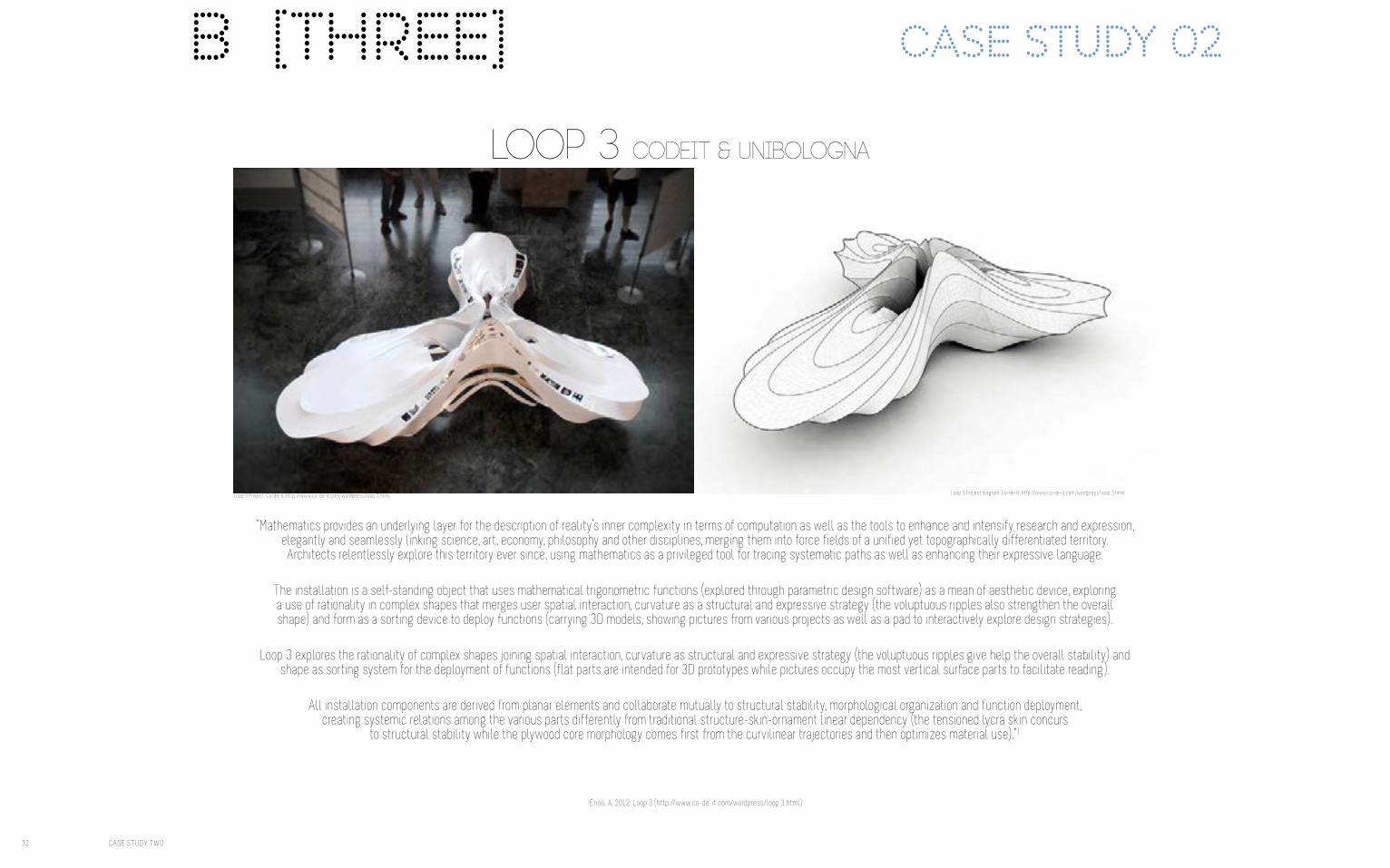
"a path to the natural urban"
46 PROPOSAL
EASTERN FREEWAY
HODDLE STREET
MAIN YARRA TRAIL
YARRA RIVERVICTORIA PARK
MELBOURNE CBD
3.5KM
NORTH
S I T E C O N T E X T
........."A PATH TO THE NATURAL URBAN"
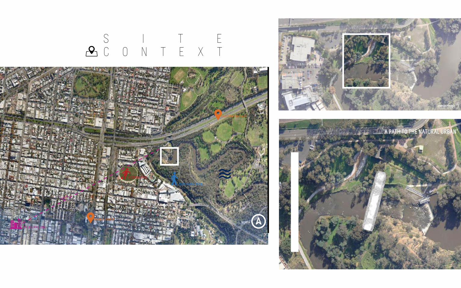
T E C H N I Q U E
From the research field, Strips and Folding, I have garnered an understanding of the technique as a great form finder.
I will use the technique to develop the overall form of the pathway and also the underground, path covering semi-circular grid-shell structure which runs underneath the main form.
I was successful in using Graph Mapper techniques to develop precise curves in all forms of the design, and these will continue to be developed and explored until an ideal form is found. The advantage of using a graph mapper component in my design is that these forms are naturally occuring mathematical phenomenons. It is in this instance that curves are an ideal starting point for development, as they link the built with the natural in a flawless, sympathetic way.
Mesh components were explored through patterning and then again with Kangaroo physics to produce ideal structural shapes which can be fabricated with ease and structural integrity.
As well as combining Stips and Folding techniques with Sectioning ideas, the interplay of Patterning occurs through meshing and triangulating surfaces.
However, limitations will occur in the fabrication stage, as I have not yet mastered how to fabricate with this technique well.
F A B R I C A T I O N
As mentioned previously in B5 Fabrication, a waffle grid fabrication method is easily employable for the desired outcome of this project.
Waffle grids are structurally sound and can fit into many different environmental contexts.
I will definitely continue to use a waffle grid for the underside of the main bridge form, but will develop the strips further to create more fluid lines which delve down into the ground, as if it appears they are emerging naturally from the landscape.
I would also like to explore the use of tabs or zip teeth to create the perforated shelter structure, or the main bridge form.
H-clips are useful for fabricating meshes, so this could be explored too.
48 PROPOSAL


B [seven] Learning Objectivesand outcomes B [eight] algorithmic
sketchbook
52 LEARNING OUTCOMES AND OBJECTIVESALGORITHMIC SKETCHBOOK 53
EVALUATING FIELDSTaking one divided element from
the original Biothing Pavillion and pushing the limits of the
spin curve components.
Changing the graph type also changed the patterning of the lines
OBJECTIVE 7: DEVELOPING ‘THE ABILITY TO MAKE A CASE FOR PROPOSALS’
In the presentation, I was able to point out the mistakes inherent in my design proposal and offer solutions for future development.
In the prototypes shown, I was quite limited in what I explored. I used a basic waffle grid, which in hind sight was far too simple and basic for what
I wanted to express.
However, it was presented to me that the sine curved, non-planar ‘waffle’ like grid was the most interesting to develop.
OBJECTIVE 8: DEVELOPMENT OF PERSONALISED REPERTOIRE OF COMPUTATIONAL TECHNIQUES
The technique development, evident in B2 and B4, it is clear that I have developed an understanding of algorithmic techniques, particularly in the
fields of attraction points, graph mapping, kangaroo physics, forces etc.
However, I understand I need to continue to learn new techniques to build a more comprehensive repetoire.
OBJECTIVE 3. DEVELOPING SKILLS IN VARIOUS THREE DIMENSIONAL MEDIA
My fabrication technique was limited to two simple waffle grid constructions, however I have expressed an interest to expand my capacities and use
different techniques.Different geometries were used via the graph mapper technique, which then
fabricated various sine curved structures.I have not yet fabricated at a small scale joint level, but will do so.
Issues of forces were expressed in B5.
OBJECTIVE 7. DEVELOP FUNDAMENTAL UNDERSTANDINGS OF COMPUTATIONAL GEOMETRY, DATA STRUCTURES AND TYPES OF
PROGRAMMINGI have highlighted selected algorithmic sketches which I deem to be successful opportunities in prototyping, form finding and technique
development.I have provided grasshopper definition diagrams to prove learning and
understanding of computational programming.I believe I was successful in reverse engineering the project in B3, and will be able to continue to reverse engineer projects I find informative to inform
further development of technique.

Graph Controllers

voissoir cloud exploration