Embed Size (px)
Citation preview

Pump Wisdom Problem Solving for Operators anaSpecialîsts
by Heinz P. Blocn
AlChE )WILEY
A JOHN WILEY & SONS, INC., PUBLICATION

r .
This page intentionally left blank

Pump Wisdom

This page intentionally left blank
Pump Wisdom Problem Solving for Operators anaSpecialîsts
by Heinz P. Blocn
AlChE )WILEY
A JOHN WILEY & SONS, INC., PUBLICATION
Cover based on ideas by Dennis Bowman, PE, Alfred Conhagen, Inc., Houston, Texas. Page layout and formatting by Joy M. Peterson, Asheville, North Carolina.
Copyright © 2011 by John Wiley & Sons, Inc. All rights reserved.
Published by John Wiley & Sons, Inc., Hoboken, New Jersey.
Published simultaneously in Canada.
No part of this publication may be reproduced, stored in a retrieval system, or transmitted in any form or by any means, electronic, mechanical, photocopying, recording, scanning, or otherwise, except as permitted under Section 107 or 108 of the 1976 United States Copyright Act, without either the prior written permission of the Publisher, or authorization through payment of the appropriate per-copy fee to the Copyright Clearance Center, Inc., 222 Rosewood Drive, Danvers, MA 01923, (978) 750-8400, fax (978) 750-4470, or on the web at www.copyright.com. Requests to the Publisher for permission should be addressed to the Permissions Department, John Wiley & Sons, Inc., I l l River Street, Hoboken, NJ 07030, (201) 748-6011, fax (201) 748-6008, or online at http://www.wiley.com/go/per-mission.
Limit of Liability/Disclaimer of Warranty: While the publisher and author have used their best efforts in preparing this book, they make no representations or warranties with respect to the accuracy or completeness of the contents of this book and specifically disclaim any implied warranties of mer-chantability or fitness for a particular purpose. No warranty may be created or extended by sales rep-resentatives or written sales materials. The advice and strategies contained herein may not be suitable for your situation. You should consult with a professional where appropriate. Neither the publisher nor author shall be liable for any loss of profit or any other commercial damages, including but not limited to special, incidental, consequential, or other damages.
For general information on our other products and services or for technical support, please contact our Customer Care Department within the United States at (800) 762-2974, outside the United States at (317) 572-3993 or fax (317) 572-4002.
Wiley also publishes its books in a variety of electronic formats. Some content that appears in print may not be available in electronic formats. For more information about Wiley products, visit our web site at www.wiley.com.
Library of Congress Cataloging-in-Publication Data:
Bloch, Heinz P., 1933-Pump wisdom : problem solving for operators and specialists / Heinz P. Bloch.
p. cm. Includes index.
ISBN 978-1-118-04123-9 (hardback) 1. Pumping machinery. I. Title. TJ900.B6483 2011 621.6'9—dc22 2010050397
Printed in the United States of America.
10 9 8 7 6 5 4 3 2 1
Tb Ken and the fellow professionals who appreciate the importance of
avoiding pump failures
V

This page intentionally left blank

Table of Contents
1. Principles of Centrifugal Process Pumps 1 Pump performance: Head and flow Operation at zero flow Impellers and rotors The meaning of specific speed Process pump types Process pump mechanical response to flow changes Recirculation and cavitation The importance of suction specific speed What we have learned References
2. Pump Selection and Industry Standards 15 Why insist on better pumps ANSI and ISO versus API pumps What we have learned References
3. Foundations and Base Plates 23 Securing pumps in place—with one exception Why not to install pump sets in the as-shipped condition Conventional versus pre-filled base plate installations Epoxy prefilled base plates How to proceed if there is no access to specialist firms What we have learned: Checklist of foundation and base plate topics References
4. Piping, Stationary Seals, and Gasketing 35 Pipe installation and support Sliding supports and installation sequence deserve special attention Monitoring pipe stress while bolting up Flange leakage What to do prior to gasket insertion
vii
Spiral wound and kammprofile gaskets Pipe, hydraulic tubing, or flexible connections? Gusseting Concentric versus eccentric reducers Vibration problems in piping What we have learned on piping and gasketing topics References
5. Rolling Element Bearings 49 Bearing selection overview and windage as a design problem Radial versus axial (thrust) bearings Oil levels, multiple bearings, and different bearing orientations Upgrading and retrofit opportunities Bearing cages Bearing preload and clearance effects Bearing dimensions and mounting tolerances What we have learned References
6. Lubricant Application and Cooling Considerations 69 Lubricant level and oil application Issues with oil rings Pressure and temperature balance in bearing housings Cooling not needed on pumps with rolling element bearings Oil delivery by constant level lubricators Black oil Lube application as oil mist (oil fog) Desiccant breathers and expansion chambers What we have learned References
7. Lubricant Types and Key Properties 83 Lubricant viscosities When and why high film strength synthetic lubricants are used Lubricants for oil mist systems What we have learned References
8. Bearing Housing Protection and Cost Justification 91 via
Noncontacting bearing protector seals Contacting bearing protector seals How venting and housing pressurization affect bearing
protector seal performance Cost justification overview Advanced bearing housing (bearing protector) seal summary What we have learned References
9. Mechanical Sealing Options for Long Life 99 Still using packing? General overview of mechanical seals All flush plans have advantages and disadvantages Always obtain the full picture Seal chamber pumping ring (circulating device) technologies Lessons apply to many services What we have learned Bibliography
10. Pump Operation 115 Starting centrifugal pumps Surveillance of pump operation Centrifugal pump shutdown What we have learned
11. Impeller Modifications and Pump Maintenance 121 Maintenance essentials Superior maintenance requires upgrading Impeller upgrading with inducers Distance from impeller tip to stationary internal casing components Impeller trimming Impeller wear rings Vane tip overfiling and underfiling What we have learned References
12. Lubrication Management 131 How bad is water contamination?
ix
Avoid solids contamination Avoid questionable storage and transfer practices Periodic audits What we have learned References
13. Pump Condition Monitoring: Pump Vibration, Rotor Balance, and Effect on Bearing Life 139 Vibration and its effect on bearing life Monitoring methods differ Vibration acceptance limits Causes of excessive vibration Rotor balancing What we have learned References
14. Drivers, Couplings, and Alignment 153 Driver selection Coupling selection and installation Installation and removal Alignment and quality criteria Consequences of misalignment Thermal rise and predefinition of growth What we have learned References
15. Fits, Dimensions, and Related Misunderstandings 163 Low incremental cost of better pumps Pump pedestals and bearing housings should not be water-cooled Summary of bearing-related issues Constant level lubricators Bearing housing protector seals ("bearing isolators") Motor lubrication summary Mechanical seal issues Hydraulic issues Impeller hydraulics Mechanical improvement or upgrade options Process pump repair dimensions
x
What we have learned References
Failure Statistics and Structured Failure Analysis 183 Mean time between failures (MTBF) and repair cost calculations Performing your own projected MTBF calculations Older pumps versus newer pumps Reliability reviews start before purchase Structured failure analysis strategies solve problems The "FRETT" approach to eradicating repeat failures of pumps What we have learned References
199
XI

This page intentionally left blank
Preface
Pump users have access to hundreds of books and many thousands of articles dealing with pump subjects. So, one might ask, why do we need this text? I believe we need it because an unacceptably large number of process pumps fail catastrophically every year. An estimated 95% of these are repeat failures, and most of them are costly, dangerous, or both. I wanted to explain some elusive failure causes and clearly map out permanent remedial action. My intent was to steer clear of the usual consultant-conceived generalities and give you tangible, factual, and well-defined information throughout.
As any close review of what has been offered in the past will uncover, many texts were written primarily to benefit one particular job function, ranging from pump operators to pump designers. Some books contain a hidden bias, or they appeal to a very narrow spectrum of readers; others are perhaps influenced by a particular pump manufacturer's agenda. Give this text a chance; you'll see that it is different. I gave it the title Pump Wisdom because wisdom is defined as applied knowledge. If you concur with this very meaningful definition you will be ready for a serious challenge. That chal-lenge is to practice wisdom by acting on the knowledge this text conveys.
Although I had written or co-authored other books and dozens of arti-cles on pump reliability improvement, some important material is too widely dispersed to be readily accessible. Moreover, some important material has never been published before. I therefore set out to assemble, rework, con-dense, and explain the most valuable points in a text aimed at wide distribu-tion. It was to become a text with, I hope, permanence and "staying power." To thus satisfy the scope and intent of this book, I endeavored to keep theo-retical explanations to a reasonable minimum and to limit the narrative to 200 pages. Putting it another way, I wanted to squeeze into these 200 pages material and topics that will greatly enhance both pump safety and reliability. All that is needed is the reader's solid determination to pay close attention and to follow up diligently.
Please realize that in years past, many pump manufacturers have pri-marily concentrated their design and improvement focus on the hydraulic end. Indeed, over time and in the decades since 1960, much advancement has been made in the metallurgical and power-efficiency-related performance of the hydraulic assembly. All the while, the mechanical assembly or drive
xiii

end of process pumps was being treated with relative indifference. In essence, there was an imbalance between the attention given to pump hydraulics and pump mechanical issues.
Recognizing indifference as costly, this text tries to rectify some of these imbalances. My narrative and illustrations are intended to do justice to both the hydraulic assembly and the mechanical assembly of process pumps. That said, the book briefly lays out how pumps function and quickly moves to guidelines and details that must be considered by reliablity-focused readers. A number of risky omissions or shortcuts by pump designers, manufacturers, and users also are described.
I also want the reader to know that the real spark for this book came from AESSEAL, a worldwide manufacturer of sealing products. I have come to appreciate them as an entity guided by quality principles, with a workforce that pursues excellence at every level of the organization. Of the many busi-ness entities I have worked with over the past five decades, they represent the one closest to my own ideal. They practice what a reliability-focused company should be doing; I consider diem an example of how a business should conduct itself. I also want to acknowledge them for rapidly providing artwork assistance whenever I asked.
Please take from me a good measure of encouragement: Make good use of this book. Read it and apply it. Today, and hopefully years from now, remember to consult this material. Doing so will acquaint you with pump failure avoidance and the more elusive aspects of preserving pump-related assets. And so, although you undoubtedly have more problems than you de-serve, please keep in mind that you also deserve access to more solutions than you previously knew about or currently apply. Sound solutions are available, and they are here, right at your fingertips. Use them wisely; they will be cost-effective. The solutions you can discern from this text will have a positive effect on pump safety performance and asset preservation. They have worked at best-of-class companies and cannot possibly disappoint you.
Heinz P. Bloch, P.E. Winter 2010/Spring 2011
xiv

Chapter 1
Principles of Centrifugal Process Pumps
Pumps, of course, are simple machines that lift, transfer, or otherwise move fluid from one place to another. They are usually configured to use the rotational (kinetic) energy from an impeller to impart motion to a fluid. The impeller is located on a shaft; together, shaft and impeller(s) make up the rotor. This rotor is surrounded by a casing; located in this casing (or pump case) are one or more stationary passageways that direct the fluid to a dis-charge nozzle. Impeller and casing are the main components of the hydraulic assembly; the region or envelope containing bearings and seals is called the mechanical assembly or power end (Figure 1.1).
Many process pumps are designed and constructed to facilitate field repair. On these so-called back pull-out pumps, shop maintenance can be performed, whereas the casing and its associated suction and discharge pip-
Figure 1.1: Principal components of an elementary process pump (Ref. 1).
1

2 Pump Wisdom
ing (Figure 1.2) are left undisturbed. Although operating in the hydraulic end, the impeller remains with the power end during removal from the field. The rotating impeller (Figure 1.3) is usually constructed with swept-back vanes and the fluid is accelerated from die rotating impeller to the stationary passages in the surrounding casing.
Figure 1.2: Typical process pump with suction flow entering horizontally and ver-tically oriented discharge pipe leaving the casing tangentially (Source: Ref. 2)
In this manner, kinetic energy is converted to potential energy and the fluid (also called pumpage) moves from the suction (lower) pressure side to the discharge (higher) pressure side of a pumping system. As the fluid leaves the impeller through the pump discharge, more fluid is drawn into the pump suction where, except for the region immediately adjacent, the pressure is lowest (Ref. 3).
Figure 1.3: A semiopen impeller with five vanes.
As shown, the impeller is configured for counter-
clockwise rotation about a centerline "A".
Principles of Centrifugal Process Pumps 3
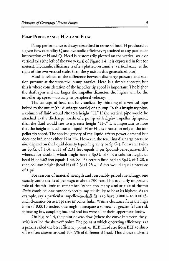
PUMP PERFORMANCE: HEAD AND FLOW
Pump performance is always described in terms of head H produced at a given flow capability Q and hydraulic efficiency r\ attained at any particular intersection of H and Q. Head is customarily plotted on the vertical scale or vertical axis (the left of the two y-axes) of Figure 1.4; it is expressed in feet (or meters). Hydraulic efficiency is often plotted on another vertical scale, at the right of the two vertical scales (i.e., the y-axis in this generalized plot).
Head is related to the difference between discharge pressure and suc-tion pressure at the respective pump nozzles. Head is a simple concept, but this is where consideration of the impeller tip speed is important. The higher the shaft rpm and the larger the impeller diameter, the higher will be the impeller tip speed—actually its peripheral velocity.
The concept of head can be visualized by thinking of a vertical pipe bolted to the outlet (the discharge nozzle) of a pump. In this imaginary pipe, a column of fluid would rise to a height "H." If the vertical pipe would be attached to the discharge nozzle of a pump with higher impeller tip speed, then the fluid would rise to a greater height "H+." It is important to note that the height of a column of liquid, H or H+, is a function only of the im-peller tip speed. The specific gravity of the liquid affects power demand but does not influence either H or H+. However, the resulting discharge pressure does depend on the liquid density (specific gravity or Sp.G.). For water (with an Sp.G. of 1.0), an H of 2.31 feet equals 1 psi (pound-per-square-inch), whereas for alcohol, which might have a Sp.G. of 0.5, a column height or head H of 4.62 feet equals 1 psi. So, if a certain fluid had an Sp.G. of 1.28, a then column height (head H) of 2.31/1.28 =1.8 feet would equal a pressure of 1 psi.
For reasons of material strength and reasonably priced metallurgy, one usually limits the head per stage to about 700 feet. This is a fairly important rule-of-thumb limit to remember. When too many similar rule-of-thumb limits combine, one cannot expect pump reliability to be at its highest. As an example, say a particular impeller-to-shaft fit is to have 0.0002- to 0.0015-inch clearance on average size impeller hubs. With a clearance fit at the high limit of 0.0015 inches, one might anticipate a somewhat greater failure risk if bearing fits, coupling fits, and seal fits were all at their uppermost limits.
On Figure 1.4, the point of zero flow (where the curve intersects the y-axis) is called the shut-off point. The point at which operating efficiency is at a peak is called the best efficiency point, or BEP. Head rise from BEP to shut-off is often chosen around 10-15% of differential head. This choice makes it
4 Pump Wisdom
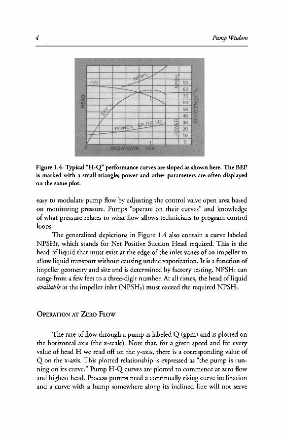
Figure 1.4: Typical "H-Q" performance curves are sloped as shown here. The BEP is marked with a small triangle; power and other parameters are often displayed on the same plot.
easy to modulate pump flow by adjusting the control valve open area based on monitoring pressure. Pumps "operate on their curves" and knowledge of what pressure relates to what flow allows technicians to program control loops.
The generalized depictions in Figure 1.4 also contain a curve labeled NPSHr, which stands for Net Positive Suction Head required. This is the head of liquid that must exist at the edge of the inlet vanes of an impeller to allow liquid transport without causing undue vaporization. It is a function of impeller geometry and size and is determined by factory testing. NPSHr can range from a few feet to a three-digit number. At all times, the head of liquid available at the impeller inlet (NPSHa) must exceed the required NPSHr.
OPERATION AT ZERO FLOW
The rate of flow through a pump is labeled Q (gpm) and is plotted on the horizontal axis (the x-scale). Note that, for a given speed and for every value of head H we read off on the y-axis, there is a corresponding value of Q on the x-axis. This plotted relationship is expressed as "the pump is run-ning on its curve." Pump H - Q curves are plotted to commence at zero flow and highest head. Process pumps need a continually rising curve inclination and a curve with a hump somewhere along its inclined line will not serve
Principles of Centrifugal Process Pumps 5
the reliability-focused user. Operation at zero flow is not allowed and, if over perhaps a minutes duration, could cause temperature increase and internal recirculation effects that might destroy most pumps.
But remember that this curve is valid only for this particular impeller pattern, geometry, size, and operation at the speed indicated by the manu-facturer or entity that produced the curve. Curve steepness or inclination has to do with the number of vanes in that impeller; curve steepness is also affected by the angle each vane makes relative to the impeller hub. In general, curve shape is verified by physical testing at the manufacturer's facility. Once the entire pump is installed in the field, it can be retested periodically by the owner-purchaser for degradation and wear progression. Power draw may have been affected by seals and couplings that differ from the ones used on the manufacturer's test stand. Occasionally, high efficiencies are alluded to in the manufacturer's literature when bearing, seal, and coupling losses are not included in the vendor's test reports.
IMPELLERS AND ROTORS
Regardless of flow classification, centrifugal pumps range in size from tiny pumps to big pumps. The tiny ones might be used in medical or labora-tory applications; the extremely large pumps may move many thousands of liters or even gallons per second from flooded lowlands to the open sea.
All six impellers in Figure 1.5 are shown with a hub fastening the im-peller to the shaft and each of the first five impellers is shown as a hub-and-disc version with an impeller cover. The cover (or "shroud") identifies the first five as "closed" impellers; recall that Figure 1.3 had depicted a semiopen impeller. Semiopen impellers are designed and fabricated without the cover. Finally, open impellers come with free-standing vanes welded to or integrally cast into the hub. Because the latter incorporate neither disc nor cover, they are often used in viscous or fibrous paper stock applications.
To function properly, a semiopen impeller must operate in close prox-imity to a casing internal surface, which is why axial adjustment features are needed with these impellers. Axial location is a bit less critical with closed impellers. Except on axial flow pumps, fluid exits the impeller in the radial direction. Radial and mixed flow pumps are either single or double suction designs; both will be shown later. Once the impellers are fastened to a shaft, the resulting assembly is called a rotor.

6 Pump Wisdom
In radial and mixed flow pumps, the number of impellers following each other, typically called "stages," can range from one to as many as will make such multistage pumps practical and economical to manufacture. Hor-izontal shaft pumps with up to 12 stages are not uncommon. With longer rotors, it becomes more difficult to avoid operating with a high vibration resonance (so-called critical speed). Vertical shaft pumps have been designed with 48 or more stages. In vertical pumps, shaft support bushings are rela-tively lightly loaded; they are spaced so as to minimize vibration risk.
T H E MEANING OF SPECIFIC SPEED
Pump impeller flow classifications and the general meaning of specific speed deserve additional discussion. Moving from left to right in Figure 1.5, the various impeller geometries reflect selections that start with high dif-ferential pressure capabilities and end with progressively lower differential pressure capabilities. Differential pressure is simply discharge pressure minus suction pressure.
Specific speed calculations are a function of several impeller parameters; the mathematical expression includes exponents and is found later in Figure 1.6. Staying with Figure 1.5 and again moving from left to right, we can reason that larger throughputs (flows) are more likely achieved by the configurations at the right, whereas larger pressure ratios (discharge pressure divided by suc-tion pressure) are usually achieved by the impeller geometries closer to the left of the illustration.
Impellers toward the right are more efficient than those near the left, and pump designers use the parameter specific speed (Ns) to bracket pump hydraulic efficiency attainment and other expected attributes of a particu-lar impeller configurations and size. Please be sure not to confuse a similar sounding parameter, pump suction specific speed (Nss or Nsss), with the specific speed (Ns). For now, we are strictly addressing specific speed (Ns).
As an example, observe the customary use, whereby with N and Q— the typical given parameters that define centrifugal process pumps—one de-termines a pivot point. Next, with pivot point and head H, one can easily determine Ns . In Figure 1.5, N s is somewhere between 500 and 15,000 on the U.S. scale. Whenever we find ourselves in that range, we know such a pump exists and we can even observe the general impeller shape. Keep in mind that thousands of impeller combination and geometries exist. Impel-
Principles of Centrifugal Process Pumps 7
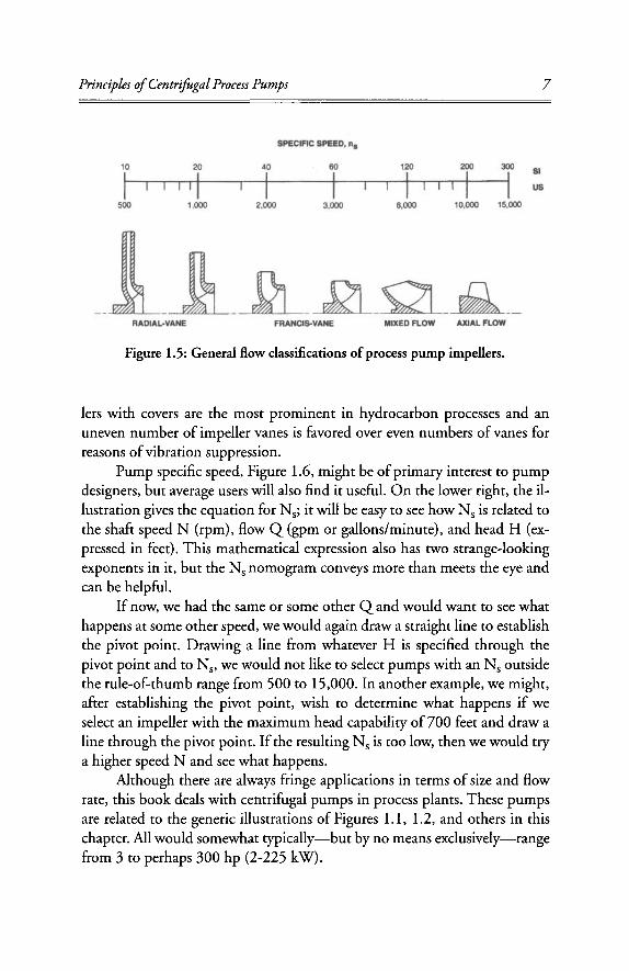
Figure 1.5: General flow classifications of process pump impellers.
lers with covers are the most prominent in hydrocarbon processes and an uneven number of impeller vanes is favored over even numbers of vanes for reasons of vibration suppression.
Pump specific speed, Figure 1.6, might be of primary interest to pump designers, but average users will also find it useful. On the lower right, the il-lustration gives the equation for Ns; it will be easy to see how N s is related to the shaft speed N (rpm), flow Q (gpm or gallons/minute), and head H (ex-pressed in feet). This mathematical expression also has two strange-looking exponents in it, but the N s nomogram conveys more than meets the eye and can be helpful.
If now, we had the same or some other Q and would want to see what happens at some other speed, we would again draw a straight line to establish the pivot point. Drawing a line from whatever H is specified through the pivot point and to Ns, we would not like to select pumps with an N s outside the rule-of-thumb range from 500 to 15,000. In another example, we might, after establishing the pivot point, wish to determine what happens if we select an impeller with the maximum head capability of 700 feet and draw a line through the pivot point. If the resulting N s is too low, then we would try a higher speed N and see what happens.
Although there are always fringe applications in terms of size and flow rate, this book deals with centrifugal pumps in process plants. These pumps are related to the generic illustrations of Figures 1.1, 1.2, and others in this chapter. All would somewhat typically—but by no means exclusively—range from 3 to perhaps 300 hp (2-225 kW).


![Daoist Alchemy in the West: The Esoteric Paradigms Lee Irwin Alche… · masters.vi[6] Daoism, like Western esotericism, is a plurality of traditions, not a unilateral institution,](https://img.dokumen.tips/doc/110x75/5f65494d2249df376504b6cc/daoist-alchemy-in-the-west-the-esoteric-paradigms-lee-irwin-alche-6-daoism.jpg)


![Windage resistance of steam-turbine wheels - NIST Pagenvlpubs.nist.gov/nistpubs/bulletin/10/nbsbulletinv10n2p191_A2b.pdf · Buckinoham] WindageLossesofSteamTurbines 193 Theunitsofm,I,and](https://img.dokumen.tips/doc/110x75/5a71c0647f8b9a98538d259b/windage-resistance-of-steam-turbine-wheels-nist-pagenvlpubsnistgovnistpubsbulletin10nbsbulletinv10n2p191a2bpdfpdf.jpg)