Embed Size (px)
Citation preview

Alcatel-Lucent 1665Data Multiplexer (1665 DMXtend) | Release 9.0
Installation Manual
365-372-327R9.0CC109696708
Issue 1July 2010

Alcatel, Lucent, Alcatel-Lucent and the Alcatel-Lucent logo are trademarks of Alcatel-Lucent. All other trademarks are the property of their respective owners.
The information presented is subject to change without notice. Alcatel-Lucent assumes no responsibility for inaccuracies contained herein.
Copyright © 2010 Alcatel-Lucent. All Rights Reserved.
Conformance statements
Federal Communications Commission (FCC) Part 15 Class A
This equipment has been tested and found to comply with the limits for a Class A digital device, pursuant to Part 15 of the FCC Rules. These limits are designed to provide reasonable protections against harmful interference when the equipment is operated in a commercial environment. This equipment generates, uses, and can radiate radio frequency energy and, if not installed and used in accordance with the instruction manual, may cause harmful interference to radio communications. Operation of this equipment in a residential area is likely to cause harmful interference, in which case the user will be required to correct the interference at the user’s expense.
Security statement
In rare instances, unauthorized individuals make connections to the telecommunications network through the use of remote access features. In such an event, applicable tariffs require that the customer pay all network charges for traffic. Alcatel-Lucent cannot be responsible for such charges and will not make any allowance or give any credit for charges that result from unauthorized access.
Limited warranty
Alcatel-Lucent provides a limited warranty for this product. For more information, consult your local Alcatel-Lucent customer support team.

i i iAlcatel-Lucent 1665 DMXtend R9.0365-372-327R9.0 Issue 1July 2010
............................................................................................................................................................................................................................................................
Contents
About this document
Purpose ........................................................................................................................................................ xi
Reason for reissue ....................................................................................................................................... xi
Intended audience ....................................................................................................................................... xii
\How to use this document ......................................................................................................................... xii
Safety information .......................................................................................................................................xv
Conventions used .........................................................................................................................................xv
Technical support ...................................................................................................................................... xvi
How to order ............................................................................................................................................. xvii
How to comment ...................................................................................................................................... xvii
Packaging collection and recovery requirements ..................................................................................... xvii
Material content compliance .................................................................................................................... xvii
1 Safety
Laser safety ............................................................................................................................................... 1-1
Electrostatic discharge ESD considerations .............................................................................................. 1-3
Laser product classification ....................................................................................................................... 1-9
Alcatel-Lucent 1665 DMXtend optical specifications ............................................................................ 1-11
Part I: Physical and power installation
2 Physical installation
Planning ..................................................................................................................................................... 2-1
Inspection .................................................................................................................................................. 2-5
Alcatel-Lucent 1665 DMXtend center divider .......................................................................................... 2-5
Alcatel-Lucent 1665 DMXtend shelf installation ..................................................................................... 2-8
Power cable installation ........................................................................................................................... 2-13
Final operations ....................................................................................................................................... 2-17
3 Cable and fiber installation
Planning ..................................................................................................................................................... 3-2
Connector references ................................................................................................................................. 3-4
............................................................................................................................................................................................................................................................i v Alcatel-Lucent 1665 DMXtend R9.0
365-372-327R9.0 Issue 1July 2010
............................................................................................................................................................................................................................................................
Contents
Inspection .................................................................................................................................................. 3-5
DS1/E1 cable installation .......................................................................................................................... 3-6
DS3/EC-1 cable installation .................................................................................................................... 3-13
10/100BASE-T Ethernet cable installation ............................................................................................. 3-40
IAO LAN and TCP/IP cable installation ................................................................................................. 3-44
Modem cable installation ........................................................................................................................ 3-47
Sync cable installation ............................................................................................................................ 3-49
Office alarm cable installation ................................................................................................................ 3-53
Miscellaneous (environmental) discrete telemetry cable installation ..................................................... 3-58
OC-3/OC-12/OC-48/OC-192 main optical fiber cable installation ........................................................ 3-62
OC-3/OC-12/OC-48 low-speed optical fiber cable installation .............................................................. 3-65
100/1000BASE-X optical fiber cable installation ................................................................................... 3-66
CIT (RS-232) cable installation .............................................................................................................. 3-68
Final operations ....................................................................................................................................... 3-70
4 Circuit pack installation
Description ................................................................................................................................................ 4-1
Powering ................................................................................................................................................... 4-2
Circuit pack compatibility ......................................................................................................................... 4-6
Initial circuit pack installation ................................................................................................................... 4-9
Part II: Stand-alone installation tests
5 Stand-alone node setup
Software installation ................................................................................................................................. 5-2
Circuit pack installation ............................................................................................................................ 5-3
Use of WaveStar® CIT software ................................................................................................................ 5-6
Circuit pack program version verification .............................................................................................. 5-13
Alcatel-Lucent 1665 DMXtend shelf initialization ................................................................................ 5-14
6 Stand-alone installation testing
LBO software settings ............................................................................................................................... 6-4
Clearing alarms ......................................................................................................................................... 6-7
Local equipment and cross-connect tests .................................................................................................. 6-8
DS1/E1 testing .......................................................................................................................................... 6-9
DS3/EC1 testing ...................................................................................................................................... 6-15
vAlcatel-Lucent 1665 DMXtend R9.0365-372-327R9.0 Issue 1July 2010
............................................................................................................................................................................................................................................................
............................................................................................................................................................................................................................................................
Contents
LNW66, LNW74, and LNW87 testing ................................................................................................... 6-21
OC-3 low-speed testing ........................................................................................................................... 6-26
OC-12 low-speed testing ......................................................................................................................... 6-30
OC-48 low-speed testing ......................................................................................................................... 6-33
LED test ................................................................................................................................................... 6-37
Office alarm test ...................................................................................................................................... 6-38
Automatic protection switching and alarm test ....................................................................................... 6-42
Manual switching tests ............................................................................................................................ 6-46
External timing verification ..................................................................................................................... 6-49
Miscellaneous (environmental) discrete telemetry test ........................................................................... 6-52
Modem connection test ........................................................................................................................... 6-54
Final operations ....................................................................................................................................... 6-56
Part III: Network turn-up and testing
7 Connecting adjacent network elements
Fiber installation ........................................................................................................................................ 7-3
Optical transmission test (OC-192, OC-48, OC-12, OC-3) .................................................................... 7-10
Automatic protection switching test ........................................................................................................ 7-11
Manual switching tests ............................................................................................................................ 7-13
Final operations ....................................................................................................................................... 7-15
8 WDMX setup and testing: integration procedures
Turn-up and test the LNW785 8-channel OMD ....................................................................................... 8-4
Turn up and test the LNW705 muxponder ................................................................................................ 8-6
Integrating the LNW705 into the LNW785 .............................................................................................. 8-9
Removing provisioning and equipage from the LNW705 and LNW785 ............................................... 8-11
Connecting the ring (Mains) to the WDMX ........................................................................................... 8-14
Removing provisioning and equipage from the LNW785 ...................................................................... 8-16
Part IV: Miscellaneous detailed installation procedure and reference material
A Fiber cleaning
Equipment requirements and recommendations ...................................................................................... A-2
Safety instructions .................................................................................................................................... A-3
Cleaning/inspecting optical connectors .................................................................................................... A-3

............................................................................................................................................................................................................................................................v i Alcatel-Lucent 1665 DMXtend R9.0
365-372-327R9.0 Issue 1July 2010
............................................................................................................................................................................................................................................................
Contents
Cleaning pluggable optics module ............................................................................................................A-9
B Pluggable Transmission Module (PTM) installation
PTM modules ............................................................................................................................................B-2
Install pluggable modules .........................................................................................................................B-8
C Installing fiber connectors and LBOs
LBOs .........................................................................................................................................................C-2
Fiber connections ......................................................................................................................................C-4
D Backplane pin replacement
Pin and connector background ..................................................................................................................D-2
Repair kits and tools ..................................................................................................................................D-3
Simple repair methods ..............................................................................................................................D-4
Replacement methods ...............................................................................................................................D-5
E Fiber labeling
Fiber description ....................................................................................................................................... E-1
Fiber labels ................................................................................................................................................ E-3
GL Glossary
GL Terms and definitions

v i iAlcatel-Lucent 1665 DMXtend R9.0365-372-327R9.0 Issue 1July 2010
............................................................................................................................................................................................................................................................
List of tables
About this document
Alcatel-Lucent 1665 DMXtend documentation set ..................................................................... xvi
1 Safety
1-1 Laser classes ............................................................................................................................... 1-10
1-2 Alcatel-Lucent 1665 DMXtend optical circuit pack laser safety specifications ........................ 1-11
1-3 Alcatel-Lucent 1665 DMXtend optical PTM laser safety specifications .................................. 1-12
1-4 Dispersion-limited receiver sensitivity for OC-192 DWDM PTMs .......................................... 1-21
I-1 Computer requirements ................................................................................................................. I-4
I-2 Installation checklist ...................................................................................................................... I-6
2 Physical installation
2-1 Cable requirements and options ................................................................................................... 2-4
2-2 Power cable assemblies .............................................................................................................. 2-16
2-3 Power connections ...................................................................................................................... 2-16
3 Cable and fiber installation
3-1 Cable requirements and options ................................................................................................... 3-3
3-2 DS1/E1 cable assemblies ............................................................................................................. 3-9
3-3 DS1 transmission connections ................................................................................................... 3-11
3-4 DS3/EC-1 cable assemblies ....................................................................................................... 3-17
3-5 Twenty-four cable DS3/EC-1 transmission connections ........................................................... 3-26
3-6 Twelve cable DS3/EC-1 transmission connections .................................................................... 3-30
3-7 DS1 and DS3 hybrid cable assemblies ....................................................................................... 3-35
3-8 DS1 and DS3 hybrid cable DS3 transmission connections ....................................................... 3-39
3-9 DS1 and DS3 hybrid cable DS1 transmission connections ....................................................... 3-39
3-10 10/100Base-T Ethernet cable assemblies ................................................................................... 3-42
3-11 10/100BaseT Ethernet connections ............................................................................................ 3-43
3-12 LAN 10BaseT cable assemblies ................................................................................................. 3-45
3-13 LAN 10Base-T cross-over cable connections ............................................................................ 3-47
3-14 LAN 10Base-T straight-through cable connections ................................................................... 3-47
3-15 Modem cable assemblies ............................................................................................................ 3-48

............................................................................................................................................................................................................................................................v i i i Alcatel-Lucent 1665 DMXtend R9.0
365-372-327R9.0 Issue 1July 2010
............................................................................................................................................................................................................................................................
List of tables
3-16 Modem cable connections .......................................................................................................... 3-49
3-17 Synchronization cable assemblies (SYNC1 and SYNC2) ......................................................... 3-52
3-18 Synchronization cable (DS1 timing reference) connections ...................................................... 3-53
3-19 Office alarm cable assemblies .................................................................................................... 3-57
3-20 Alarm office connections ........................................................................................................... 3-57
3-21 Miscellaneous discrete cable assemblies ................................................................................... 3-61
3-22 Miscellaneous (environmental) discrete telemetry connections ................................................ 3-61
3-23 CIT Cable Assembly .................................................................................................................. 3-69
3-24 Standard CIT cable connection .................................................................................................. 3-69
3-25 RJ-45 to DB-9 connector connections ....................................................................................... 3-70
4 Circuit pack installation
4-1 Alcatel-Lucent 1665 DMXtend shelf power supply requirements .............................................. 4-2
4-2 R9.0 circuit pack slot compatibility ............................................................................................. 4-6
6 Stand-alone installation testing
6-1 Office alarm connections ........................................................................................................... 6-39
6-2 Miscellaneous (environmental) discrete telemetry connections ................................................ 6-54
7 Connecting adjacent network elements
7-1 Attenuation table .......................................................................................................................... 7-6
8 WDMX setup and testing: integration procedures
8-1 Channel/port assignments .......................................................................................................... 8-13
8-2 XM10G/8 PTM port guidelines ................................................................................................. 8-14
8-3 Channel/port assignments ......................................................................................................... 8-19
8-4 Attenuation Table ....................................................................................................................... 8-19
A Fiber cleaning
A-1 Required and recommended equipment and materials ................................................................A-2
B Pluggable Transmission Module (PTM) installation
B-1 Alcatel-Lucent approved PTMs ...................................................................................................B-2
D Backplane pin replacement
D-1 Backplane locations of METRAL™ pins ....................................................................................D-3
D-2 Metral™ pins ...............................................................................................................................D-3

i xAlcatel-Lucent 1665 DMXtend R9.0365-372-327R9.0 Issue 1July 2010
............................................................................................................................................................................................................................................................
List of figures
1 Safety
1-1 Static control wrist strap ............................................................................................................... 1-5
2 Physical installation
2-1 Shelf mount rear cover kit 849001367 ......................................................................................... 2-3
2-2 Bay mount rear cover kit 849001060 ........................................................................................... 2-4
2-3 Center divider ............................................................................................................................... 2-6
2-4 Center divider with circuit packs installed. .................................................................................. 2-7
2-5 Alcatel-Lucent 1665 DMXtend mounting bracket positions - 23-Inch/19-Inch frame ............. 2-10
2-6 Fiber duct mounting ................................................................................................................... 2-11
2-7 Safety ground screw. .................................................................................................................. 2-12
2-8 Fiber spools ................................................................................................................................ 2-13
2-9 Power connection ....................................................................................................................... 2-14
3 Cable and fiber installation
3-1 Connector types and pinouts ........................................................................................................ 3-5
3-2 DS1/E1 cable connectors ............................................................................................................. 3-7
3-3 DS1/E1 cable routing to the right ................................................................................................. 3-8
3-4 DS1/E1 cable routing to the left ................................................................................................... 3-8
3-5 DS3/EC-1 cable connections ..................................................................................................... 3-15
3-6 DS3/EC-1 cable routing to the right .......................................................................................... 3-15
3-7 DS3/EC-1 cable routing to the left ............................................................................................ 3-16
3-8 DS1 and DS3 hybrid cable connections ..................................................................................... 3-33
3-9 DS1 and DS3 hybrid cable routing ........................................................................................... 3-33
3-10 10/100BASE-T/TX cable connections ....................................................................................... 3-41
3-11 10/100BASE-T cable routing ..................................................................................................... 3-41
3-12 IAO LAN/TCP-IP cable connection to rear of Alcatel-Lucent 1665 DMXtend ...................... 3-45
3-13 Modem cable connection .......................................................................................................... 3-48
3-14 Sync cable connections .............................................................................................................. 3-50
3-15 Office alarm cable connections .................................................................................................. 3-55
3-16 Office alarm cable routing .......................................................................................................... 3-55
............................................................................................................................................................................................................................................................x Alcatel-Lucent 1665 DMXtend R9.0
365-372-327R9.0 Issue 1July 2010
............................................................................................................................................................................................................................................................
List of figures
3-17 Miscellaneous discrete cable connection .................................................................................. 3-59
3-18 Miscellaneous discrete cable routing ........................................................................................ 3-59
3-19 Optical fiber routing .................................................................................................................. 3-64
4 Circuit pack installation
4-1 Power connections on Alcatel-Lucent 1665 DMXtend backplane .............................................. 4-4
4-2 Alcatel-Lucent 1665 DMXtend shelf ........................................................................................... 4-8
6 Stand-alone installation testing
6-1 Alcatel-Lucent 1665 DMXtend shelf backplane ....................................................................... 6-51
6-2 Miscellaneous (environmental) discrete functions ................................................................... 6-53
A Fiber cleaning
A-1 Cleaning the ferrule endface ........................................................................................................A-4
A-2 CLETOP cleaner ..........................................................................................................................A-5
A-3 Acceptability criteria for fiber cleaning .....................................................................................A-7
B Pluggable Transmission Module (PTM) installation
B-1 Pluggable optics module ..............................................................................................................B-8
B-2 Module types ................................................................................................................................B-9
B-3 Latch type 3 ...............................................................................................................................B-11
B-4 Latch type 4 ................................................................................................................................B-11
B-5 Electrical PTM routing ..............................................................................................................B-14
C Installing fiber connectors and LBOs
C-1 LC-type connector ports on circuit pack ......................................................................................C-2
C-2 LC-type LBO ...............................................................................................................................C-3
C-3 LC-type LBO inserted into LC-type connector port ...................................................................C-3
C-4 Removing LC-type LBO from LC-type connector port ..............................................................C-4
C-5 LC-type fiber connector ...............................................................................................................C-5
C-6 LC-type fiber connection .............................................................................................................C-5

xiAlcatel-Lucent 1665 DMXtend R9.0365-372-327R9.0 Issue 1July 2010
............................................................................................................................................................................................................................................................
About this document
Purpose
This document provides the information and procedures necessary to install, self-test and turn up Alcatel-Lucent 1665 Data Multiplexer Extend (Alcatel-Lucent 1665 DMXtend).
Reason for reissue
This document is being reissued to include information about new features and hardware associated with R9.0 including:
• LNW87 Private Line Ethernet circuit pack supports up to four PTM-based FE or GigE optical/electrical interfaces. All FE and GigE optical and electrical PTMs currently supported by Alcatel-Lucent 1665 DMXtend are compatible with the LNW87.
• LNW302 OC-3 Main circuit pack supports a single PTM-based OC-3 signal. All OC-3 PTMs currently supported by Alcatel-Lucent 1665 DMXtend are compatible with the LNW302.
• LNW382 OC-12 Main circuit pack supports a single PTM-based OC-12 signal. All OC-12 PTMs currently supported by Alcatel-Lucent 1665 DMXtend are compatible with the LNW382.
• LNW705 Muxponder circuit pack (XM10G/8) multiplexes up to 8 ports of high bandwidth client interfaces onto a single 10G wavelength is supported in the G2 slot.
• 100BASE-FX-I1 and 100BASE-ZX-I1 FE PTMs support on LNW74, LNW87, and LNW170.
• OC3X12X48-LR1-I1 and OC3X12X48-IR1-I1 multi-rate PTM for LNW84.
• G.8032 Ethernet Ring Protection (ERP) support on the LNW170.
• SSH File Transfer Protocol (SFTP) supported for software download, database backup, and database restoration.
• SNMP v3 Monitoring (gets and traps).
• RADIUS authentication support for user login.
............................................................................................................................................................................................................................................................xii Alcatel-Lucent 1665 DMXtend R9.0
365-372-327R9.0 Issue 1July 2010
............................................................................................................................................................................................................................................................
About this document
Intended audience
This installation manual is intended to provide individuals and customers the information and procedures necessary to install, self-test and turn up the Alcatel-Lucent 1665 DMXtend system.
This manual is not a service or operations manual. For any activities involving circuit turn-up, regular maintenance, or trouble analysis, see
• Alcatel-Lucent 1665 Data Multiplexer Extend (DMXtend) User Operations Guide 365-372-325
• Alcatel-Lucent 1665 Data Multiplexer Extend (DMXtend) Maintenance and Trouble Clearing Guide 365-372-326
\How to use this document
This manual is divided into the following sections with a brief description of the contents of each major part/chapter/appendix:
About this document
This chapter describes the purpose, intended audience, reason for reissue, and organization of this document. This section references related documentation and explains how to order, make comments or recommend changes to this document.
Chapter 1, “Safety”
This chapter provides laser safety information and precautions.
Part I: “Physical and power installation”
Part I covers Chapters 2, 3, and 4. These sections covers the physical mounting of the Alcatel-Lucent 1665 DMXtend shelf using the Horizontal Bay Mount. This section includes the running and connecting of power cables, interconnecting cables, alarm cables, and as required, external timing, communication cables, and covers initial circuit pack installation (not seated). This section also provides the recommended checklist Table I-2 “Installation checklist” to follow when installing a Alcatel-Lucent 1665 DMXtend system. Use of the installation checklist is required to ensure a quality installation. All completed tasks should be checked off and those not completed should be duly noted as to the reason why. This checklist should be turned in as part of your job complete paperwork.
Chapter 2, “Physical installation”
This chapter provides equipment installation instructions for the Alcatel-Lucent 1665 DMXtend shelf using the horizontal bay mount configuration. The Alcatel-Lucent 1665 DMXtend shelves with the removable center divider can support either half width or full width cards in the Main function slots.

............................................................................................................................................................................................................................................................Alcatel-Lucent 1665 DMXtend R9.0365-372-327R9.0 Issue 1July 2010
xi i i
............................................................................................................................................................................................................................................................
About this document
Chapter 3, “Cable and fiber installation”
This chapter provides cabling instructions for the Alcatel-Lucent 1665 DMXtend shelf using the horizontal bay mount configuration.
Chapter 4, “Circuit pack installation”
This chapter provides information for verifying that the shelf is being supplied with the proper power and provides instructions for circuit pack installation.
Part II: “Stand-alone installation tests”
Part II covers Chapters 5 and 6. These sections cover the initial Graphical User Interface (GUI) or Craft Interface Terminal (CIT) software installation and turn-up testing on a new Alcatel-Lucent 1665 DMXtend shelf. It is intended to verify correct electrical DS1/DS3/FE cable wiring to the DSX panel or punch down block as well SONET fiber routing to the LGX panel from the faceplates of installed packs. This section also the recommended checklist “Installation checklist” to follow when installing a Alcatel-Lucent 1665 Data Multiplexer Extend (Alcatel-Lucent 1665 DMXtend) system. Use of the installation checklist is required to ensure a quality installation. All completed tasks should be checked off and those not completed should be duly noted as to the reason why. This checklist should be turned in as part of your job complete paperwork.
Chapter 5, “Stand-alone node setup”
This chapter provides procedures for initial Graphical User Interface (GUI) or Craft Interface Terminal (CIT) software installation and circuit packs provided via work order. Also, the use of the Graphical User Interface (GUI) or Craft Interface Terminal (CIT).
Chapter 6, “Stand-alone installation testing”
This chapter is to verify proper transmission cabling installation and R9.0 functionality as well as the associated functionality of the Alcatel-Lucent 1665 DMXtend shelf.
Part III: “Network turn-up and testing”
Part III covers fiber connections between nodes in a ring. It is not intended to replace acceptance test procedures. This section also provides the recommended checklist “Installation checklist” to follow when installing a Alcatel-Lucent 1665 DMXtend system. Use of the installation checklist is required to ensure a quality installation. All completed tasks should be checked off and those not completed should be duly noted as to the reason why. This checklist should be turned in as part of your job complete paperwork.
Chapter 7, “Connecting adjacent network elements”
This chapter is used to make fiber connections between nodes in a ring. It is not intended to replace acceptance test procedures.

............................................................................................................................................................................................................................................................xiv Alcatel-Lucent 1665 DMXtend R9.0
365-372-327R9.0 Issue 1July 2010
............................................................................................................................................................................................................................................................
About this document
Chapter 8, “WDMX setup and testing: integration procedures”
This chapter is used to verify WDMX connectivity between Alcatel-Lucent 1665 Data Multiplexer Extend (Alcatel-Lucent 1665 DMXtend) nodes. The chapter includes the LNW785 8 channel Optical Multiplexer Demultiplexer (OMD) circuit pack. It is not intended to replace acceptance test procedures.
Part IV: “Miscellaneous detailed installation procedure and reference material”
Part IV provides supplementary information that is useful when installing the Alcatel-Lucent 1665 DMXtend system and using this Installation Manual.
Appendix A, “Fiber cleaning”
This appendix describes the Alcatel-Lucent recommended method for the cleaning and inspection of optical connectors using specific tools and materials that have been proven to be effective in the assembly and testing of optical transmission equipment.
Appendix C, “Installing fiber connectors and LBOs”
This appendix provides procedures for installing and removing the types of Line Build Out units (LBOs) and fiber connectors onto input and output ports found on the Alcatel-Lucent 1665 DMXtend circuit packs.
Appendix D, “Backplane pin replacement”
This appendix provides information and the procedures used when a pin or blade on the Alcatel-Lucent 1665 DMXtend backplane has been bent or broken.
Appendix E, “Fiber labeling”
This appendix describes the labeling of the fiber.
Glossary
The Glossary provides definitions for telecommunication acronyms and terms.
Index
The Index supplies users with specific subjects and corresponding page numbers to find necessary information.
Safety information
This information product contains hazard statements for your safety. Hazard statements are given at points where safety consequences to personnel, equipment, and operation may exist. Failure to follow these statements may result in serious consequences.

............................................................................................................................................................................................................................................................Alcatel-Lucent 1665 DMXtend R9.0365-372-327R9.0 Issue 1July 2010
xv
............................................................................................................................................................................................................................................................
About this document
Safety precautions
Adhere to the following safety precautions:
• Electrostatic discharge (ESD)
You must be properly grounded when making contact with the Alcatel-Lucent 1665 DMXtend frame and handling circuit packs, disk drives, and tapes. Wrist strap ground cords should be routinely tested for the minimum 1-megohm resistance.
• Plug-in storage
Circuit packs should be stored in static-safe packaging or in a grounded cabinet.
For additional safety precautions, please see the Alcatel-Lucent 1665 Data Multiplexer Extend (DMXtend) User Operations Guide 365-372-325.
Conventions used
Italic typeface denotes a particular product line or information product.
Arial Bold typeface signifies a window, section, command or parameter used with the Graphical User Interface
Helvetica typeface indicates a faceplate or Alcatel-Lucent 1665 DMXtend label designation, as in the ACTIVE LED on a circuit pack.
Courier Bold indicates a TL1 command typed in a terminal window by the user, as in act-user:LT-DMXTEND:LUC01:ctag::DMXTND2.5G;
Courier typeface indicates the system or PC response to a command.
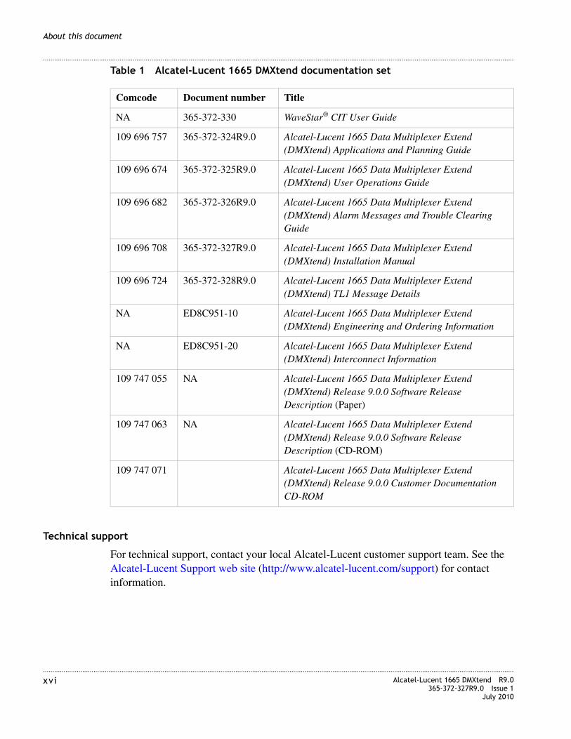
Alcatel-Lucent 1665 DMXtend Documentation Set
The following table lists the documents included in the Alcatel-Lucent 1665 DMXtend documentation set.
CAUTION
Laser Safety
When connecting fiber loops between the IN and OUT ports on optical circuit packs, always connect to the IN port first and then the OUT port. This will prevent any optical radiation from being present at the fiber end.For more detailed information and safety precautions, see Chapter 1, “Safety”.
............................................................................................................................................................................................................................................................xvi Alcatel-Lucent 1665 DMXtend R9.0
365-372-327R9.0 Issue 1July 2010
............................................................................................................................................................................................................................................................
About this document
Table 1 Alcatel-Lucent 1665 DMXtend documentation set
Technical support
For technical support, contact your local Alcatel-Lucent customer support team. See the Alcatel-Lucent Support web site (http://www.alcatel-lucent.com/support) for contact information.
Comcode Document number Title
NA 365-372-330 WaveStar® CIT User Guide
109 696 757 365-372-324R9.0 Alcatel-Lucent 1665 Data Multiplexer Extend (DMXtend) Applications and Planning Guide
109 696 674 365-372-325R9.0 Alcatel-Lucent 1665 Data Multiplexer Extend (DMXtend) User Operations Guide
109 696 682 365-372-326R9.0 Alcatel-Lucent 1665 Data Multiplexer Extend (DMXtend) Alarm Messages and Trouble Clearing Guide
109 696 708 365-372-327R9.0 Alcatel-Lucent 1665 Data Multiplexer Extend (DMXtend) Installation Manual
109 696 724 365-372-328R9.0 Alcatel-Lucent 1665 Data Multiplexer Extend (DMXtend) TL1 Message Details
NA ED8C951-10 Alcatel-Lucent 1665 Data Multiplexer Extend (DMXtend) Engineering and Ordering Information
NA ED8C951-20 Alcatel-Lucent 1665 Data Multiplexer Extend (DMXtend) Interconnect Information
109 747 055 NA Alcatel-Lucent 1665 Data Multiplexer Extend (DMXtend) Release 9.0.0 Software Release Description (Paper)
109 747 063 NA Alcatel-Lucent 1665 Data Multiplexer Extend (DMXtend) Release 9.0.0 Software Release Description (CD-ROM)
109 747 071 Alcatel-Lucent 1665 Data Multiplexer Extend (DMXtend) Release 9.0.0 Customer Documentation CD-ROM

............................................................................................................................................................................................................................................................Alcatel-Lucent 1665 DMXtend R9.0365-372-327R9.0 Issue 1July 2010
xvi i
............................................................................................................................................................................................................................................................
About this document
How to order
To order Alcatel-Lucent documents contact your local sales representative or use Online Customer Support (OLCS) (https://support.alcatel-lucent.com).
How to comment
To comment on this document, go to the Online Comment Form (http://infodoc.alcatel-lucent.com/comments) or email your comments to the Comments Hotline ([email protected]).
Packaging collection and recovery requirements
Countries, states, localities, or other jurisdictions may require that systems be established for the return and/or collection of packaging waste from the consumer, or other end user, or from the waste stream. Additionally, reuse, recovery, and/or recycling targets for the return and/or collection of the packaging waste may be established.
For more information regarding collection and recovery of packaging and packaging waste within specific jurisdictions, please contact the Alcatel-Lucent Services - Environmental Health and Safety organization.
Material content compliance
European Union RoHS
European Union (EU) Directive 2002/95/EC, “Restriction of the use of certain Hazardous Substances” (RoHS), restricts the use of lead, mercury, cadmium, hexavalent chromium, and certain flame retardants in electrical and electronic equipment. This Directive applies to electrical and electronic products placed on the EU market after 1 July 2006, with various exemptions, including an exemption for lead solder in network infrastructure equipment. Alcatel-Lucent products shipped to the EU after 1 July 2006 comply with the EU RoHS Directive.
China RoHS
The Peoples Republic of China Ministry of Information Industry has published a regulation (Order #39) and associated standards regarding restrictions on hazardous substances (China RoHS). Currently, the legislation requires all Electronic and Information Products (EIP) to comply with certain labeling and documentation requirements. Alcatel-Lucent products manufactured on or after 1 March 2007, that are intended for sale to customers in the China market, comply with these requirements.

............................................................................................................................................................................................................................................................xvii i Alcatel-Lucent 1665 DMXtend R9.0
365-372-327R9.0 Issue 1July 2010
............................................................................................................................................................................................................................................................
About this document
In accordance with the People’s Republic of China Electronic Industry Standard “Marking for the Control of Pollution Caused by Electronic Information Product” (SJ/T11364- 2006), customers may access Alcatel-Lucent’s Hazardous Substances Table information at either of the following two URLs (for the convenience of our diverse customer base):
• Access via the Alcatel-Lucent Corporate website at: http://www.alcatel-sbell.com.cn/live/home/index.jsp (http://www.alcatel-sbell.com.cn/
• Access via the Alcatel Shanghai Bell website at: http://www.alcatel-sbell.com.cn/wwwroot/images/upload/private/1/media/China-RoHS-HST-3.1.pdf (http://www.alcatel-sbell.com.cn/wwwroot/images/upload/
Recycling/take-back/disposal of product
Electronic products bearing or referencing the symbols shown below shall be collected and treated at the end of their useful life, in compliance with applicable European Union and other local legislation. They shall not be disposed of as part of unsorted municipal waste. Due to materials that may be contained in the product and batteries, such as heavy metals, the environment and human health may be negatively impacted as a result of inappropriate disposal.
Note: For electronic products put on the market in the European Union, a solid bar under the crossed-out wheeled bin indicates that the product was put on the market.
Moreover, in compliance with legal requirements and contractual agreements, where applicable, Alcatel-Lucent will offer to provide for the collection and treatment of Alcatel-Lucent products bearing the logo at the end of their useful life, or products. For information regarding take-back, recycling, or disposal of equipment by Alcatel-Lucent or for equipment take-back requests, visit the Alcatel-Lucent Take-Back web page (http://www.alcatel-lucent.com/product_takeback) or contact Alcatel-Lucent Take-Back Support ([email protected]). For technical information on product treatment, consult the Alcatel-Lucent Recycling Information web page.

1-1Alcatel-Lucent 1665 DMXtend R9.0365-372-327R9.0 Issue 1July 2010
............................................................................................................................................................................................................................................................
1 Safety
Overview
Purpose
This chapter provides important safety instructions for the Alcatel-Lucent 1665 Data Multiplexer Extend (Alcatel-Lucent 1665 DMXtend).
Contents
This appendix provides information on the following topics:
Laser safety
System design
The Alcatel-Lucent system complies with FDA/CDRH 21 CFR 1040.10 and 1040.11 as a Class I and with IEC 60825-1 as a Class 1 Optical Fiber Telecommunication laser product. The system has been designed to ensure that the operating personnel is not endangered by laser radiation during normal system operation. The safety measures specified in the Food and Drug Administration’s Center for Devices and Radiological Health (FDA/CDRH) regulations and the international standards IEC-60825 or DIN/EN 60825 are met. Please also see “Laser product classification” (p. 1-9).
Laser safety 1-1
Electrostatic discharge ESD considerations 1-3
Laser product classification 1-9
Alcatel-Lucent 1665 DMXtend optical specifications 1-11

............................................................................................................................................................................................................................................................1-2 Alcatel-Lucent 1665 DMXtend R9.0
365-372-327R9.0 Issue 1July 2010
............................................................................................................................................................................................................................................................
Safety
Potential sources of danger
Beware of the following potential sources of danger which will remain despite all safety measures taken:
• Laser radiation can cause damage to the skin and eyes.
• Laser radiation from optical transmission systems is in a wavelength range that is invisible to the human eye.
Laser warning labels
The laser warning labels indicate either only the laser class or both the laser class and the maximum output power of laser radiation. The following figure shows different types of laser warning labels and their characteristics.
CAUTION
Do not view directlywith opticalinstruments.
CLASS 1M INVISIBLELASER RADIATIONWHEN OPENAND FIBERDISCONNECTED.
ATTENTIONRAYONNEMENTLASER DE CLASSE1M INVISIBLELORSQUEL’APPAREIL ESTOUVERT ET QUELA FIBRE ESTDÉCONNECT E.Ne pas regarderdirectement au moyend’un instrument optique.
É
848950572
H
H
HAZARDLEVEL
1M
1
2
3
CLASS 1 LASER
PRODUCT
H
DANGER
INVISIBLE LASER RADIATIONWHEN OPEN AND FIBERDISCONNECTED
Avoid direct exposure to beamDo not view beam directly withoptical instruments

............................................................................................................................................................................................................................................................Alcatel-Lucent 1665 DMXtend R9.0365-372-327R9.0 Issue 1July 2010
1-3
............................................................................................................................................................................................................................................................
Safety
Legend
1. Laser symbol.
2. Laser classification label. This label may show only the laser class or both the laser class and the maximum output power.
3. Laser warning label.
Laser safety instructions
Observe the following instructions to avoid exposing yourself and others to risk.
• Read the relevant descriptions in the manuals before taking equipment into operation or carrying out any installation and maintenance work on the optical port units, and follow the instructions. Ignoring the instructions can result in exposure to dangerous radiation.
• Do not view directly into the laser beam with optical instruments such as a fiber microscope, because viewing of laser emission in excess of Class 1 limits significantly increases the risk of eye damage.
• Never look into the end of an exposed fiber or an open connector as long as the optical source is still switched on.
• Ensure that the optical source is switched off before disconnecting optical fiber connectors.
• In the event of doubt, check that the optical source is switched off by measuring with an optical power meter.
• When connecting fiber loops between the IN and OUT ports on optical circuit packs, always connect to the IN port first and then the OUT port. This will prevent any optical radiation from being present at the fiber end.
Electrostatic discharge ESD considerations
ESD precautions
Industry experience has shown that all integrated circuit packs can be damaged by static electricity that builds up on work surfaces and personnel. The static charges are produced by various charging effects of movement and contact with other objects. Dry air allows greater static charges to accumulate. Higher potentials are measured in areas with low relative humidity, but potentials high enough to cause damage can occur anywhere.
CAUTION
ESD hazard

............................................................................................................................................................................................................................................................1-4 Alcatel-Lucent 1665 DMXtend R9.0
365-372-327R9.0 Issue 1July 2010
............................................................................................................................................................................................................................................................
Safety
In order to prevent damage by electrostatic discharge the following precautions should be observed when handling circuit packs:
• Assume all circuit packs contain solid state electronic components that can be damaged by ESD.
• When handling circuit packs (storing, inserting, removing, etc.) or when working on the backplane, always wear a grounded wrist strap such as the one shown in Figure 1-1, “Static control wrist strap” (p. 1-5) or wear a heel strap and stand on a grounded, static dissipating floor mat. If a static dissipating floor mat is used, be sure that it is clean to ensure a good discharge path.
• Handle all circuit packs by the faceplate or latch and by the top and bottom outermost edges. Never touch the components, conductors, or connector pins.
• Observe warning labels on bags and cartons. Whenever possible, do not remove circuit packs from antistatic packaging until ready to insert them into slots.
• If possible, open all circuit packs at a static safe work position, using properly grounded wrist straps and static dissipating table mats. If a static dissipating floor mat is used, be sure that it is clean to ensure a good discharge path.
• Always store and transport circuit packs in static safe packaging. Shielding is not required unless specified.
• Keep all static generating materials such as food wrappers, plastics, and styrofoam containers away from all circuit packs. Upon removal from bay, immediately put circuit packs into static safe packages.
• Whenever possible, maintain relative humidity above 20 percent.
To reduce the possibility of ESD damage, assemblies are equipped with grounding jacks to enable personnel to ground themselves using wrist straps [Figure 1-1, “Static control wrist strap” (p. 1-5)] while handling circuit packs or working on an assembly. The jacks for connection of wrist straps are located at the lower right-hand corner of each assembly and are labeled. When grounding jacks are not provided, an alligator clip adapter enables connection to bay frame ground.

............................................................................................................................................................................................................................................................Alcatel-Lucent 1665 DMXtend R9.0365-372-327R9.0 Issue 1July 2010
1-5
............................................................................................................................................................................................................................................................
Safety
Figure 1-1 Static control wrist strap
TOGROUNDCONNECTION

............................................................................................................................................................................................................................................................1-6 Alcatel-Lucent 1665 DMXtend R9.0
365-372-327R9.0 Issue 1July 2010
............................................................................................................................................................................................................................................................
Safety
IMPORTANT SAFETY INSTRUCTIONS
READ AND UNDERSTAND ALL INSTRUCTIONS
The exclamation point within an equilateral triangle is intended to alert the user to the presence of important operating and maintenance (servicing) instructions in the literature accompanying this product.
When installing, operating, or maintaining this equipment, basic safety precautions should always be followed to reduce the risk of fire, electric shock, and injury to persons, including the following:
1. Read and understand all instructions.
2. Follow all warnings and instructions marked on this product.
3. This product should be only operated from the type of power sources indicated on the marking label.
4. Connect this product only to the type of power sources recommended by Alcatel-Lucent. For information on the powering instructions, consult the Installation Manual.
5. This equipment is suitable for mounting on a concrete or other noncombustible surface only.
6. For information on proper mounting instructions, consult the Installation Manual.
7. Install only equipment identified in the Installation Manual. Use of other equipment may result in improper connection of circuitry leading to fire or injury to persons.
8. All metallic telecommunication interfaces should not leave the building premises unless connected to telecommunication devices providing primary and secondary protection, as applicable.
9. Do not use this product near water, for example, in a wet basement.
10. Do not place this product on an unstable cart, stand or table. The product may fall, causing serious damage to the product.
11. Use caution when installing or modifying telecommunications lines.
12. Never install telecommunications wiring during a lightning storm.
13. Never install telecommunications connections in wet locations.
14. Never touch uninsulated telecommunications wires or terminals unless the telecommunications line has been disconnected at the network interface.
15. Never touch uninsulated wiring or terminals carrying direct current or ringing current, or leave this wiring exposed. Protect and tape uninsulated wiring and terminals to avoid risk of fire, electric shock, and injury to service personnel.
16. Never push objects of any kind into this product through slots as they may touch dangerous voltage points or short out parts that could result in a risk of fire or electrical shock. Never spill liquids of any kind on the product.

............................................................................................................................................................................................................................................................Alcatel-Lucent 1665 DMXtend R9.0365-372-327R9.0 Issue 1July 2010
1-7
............................................................................................................................................................................................................................................................
Safety
17. Slots and openings in the unit are provided for ventilation, to protect it from overheating, and these openings must not be blocked or covered. This product should not be placed in a built-in installation unless proper ventilation is provided.
18. To reduce the risk of an electrical shock, do not disassemble this product. Service should be performed by trained personnel only. Opening or removing covers and/or circuit boards may expose you to dangerous voltages or other risks. Incorrect reassembly can cause electrical shock when the unit is subsequently used.
19. Some of the Alcatel-Lucent 1665 Data Multiplexer Extend (Alcatel-Lucent 1665 DMXtend) hardware modules contain FDA/CDRH Class I/IEC Class 1 single-mode laser products that are enclosed lightwave transmission systems. Under normal operating conditions, lightwave transmission systems are completely enclosed; nonetheless, the following precautions must be observed because of the potential for eye damage:
• Do not disconnect any lightwave cable or splice and stare into the optical connectors terminating the cables.
• Lightwave/lightguide operations should not be performed by a technician who has not satisfactorily completed an approved training course.
• Do not use optical instruments such as an eye loupe to view a fiber or unterminated connector.
• More information about laser safety can be found in the Installation Manual.
20. For a unit intended to be powered from –48 V dc voltage sources, read and understand the following:
• To be powered only by Safety Extra Low Voltage (SELV) -48 V dc Sources.
• Disconnect up to Two (2) power supply connections when removing power from the system.
• This equipment must be provided with a readily accessible disconnect device as part of the building installation.
• Ensure that there is no exposed wire when the input power cables are connected to the unit.
• Installation must include an independent frame ground drop to building ground. See Alcatel-Lucent 1665 Data Multiplexer Extend (DMXtend) User Operations Guide 365-372-325
This symbol is marked on the product, adjacent to the ground (earth) area for the connection of the ground (earth) conductor.

............................................................................................................................................................................................................................................................1-8 Alcatel-Lucent 1665 DMXtend R9.0
365-372-327R9.0 Issue 1July 2010
............................................................................................................................................................................................................................................................
Safety
• This Equipment is to be Installed Only in Restricted Access Areas on Business and Customer Premises Applications in Accordance with Articles 110-16, 110-17, and 110-18 of the National Electrical Code, ANSI/NFPA No. 70. Other Installations Exempt from the Enforcement of the National Electrical Code May Be Engineered According to the Accepted Practices of the Local Telecommunications Utility.
21. For a unit intended to be powered from 100-120/200-240 V ac voltage sources, read and understand the following:
• Unplug this product from the wall outlet before cleaning. Do not use liquid cleaners or aerosol cleaners. Use a damp cloth for cleaning.
• Do not staple or otherwise attach the power supply cord to the building surfaces.
• Do not overload wall outlets and extension cords as this can result in the risk of fire or electric shock.
• The socket outlet should be installed near the equipment and should be readily accessible.
• This product is equipped with a three-wire grounding type plug, a plug having a third (grounding) pin. This plug is intended to fit only into a grounding type power outlet. This is a safety feature. If you are unable to insert the plug into the outlet, contact your electrician to replace your obsolete outlet. Do not defeat the safety purpose of the grounding type plug. Do not use a 3-to-2-prong adapter at the receptacle. Use of this type adapter may result in risk of electrical shock and/or damage to this product.
• Do not allow anything to rest on the power cord. Do not locate this product where the cord may be abused by persons walking on it.
• Unplug this product from the wall outlet and refer servicing to qualified service personnel under the following conditions:
a. When the powers supply cord or plug is damaged or frayed.
b. If liquid has been spilled into the product.
c. If the product has been exposed to rain or water.
d. If the product does not operate normally by following the operating instructions. Adjust only those controls that are covered by the operating instructions because improper adjustment of other controls may result in damage and will often require extensive work by qualified technician to restore the product to normal operation.
e. If the product has been dropped or the cabinet has been damaged.
f. If the product exhibits a distinct change in performance.
SAVE THESE INSTRUCTIONS

............................................................................................................................................................................................................................................................Alcatel-Lucent 1665 DMXtend R9.0365-372-327R9.0 Issue 1July 2010
1-9
............................................................................................................................................................................................................................................................
Safety
Laser product classification
Standards compliance
The product complies with both IEC standards and the Food and Drug Administration’s Center for Devices and Radiological Health (FDA/ CDRH) regulations.
FDA/CDRH regulations
Laser products are classified in accordance with the FDA/CDRH - 21 CFR 1010 and 1040. The classification scheme is based on the ability of the laser emission to cause injury to eye or skin during normal operating conditions.
In the United States, lasers and laser systems in the infrared wavelength range (greater than 700 nm) are assigned to one of the following classes:
• Class I,
• Class IIIb, or
• Class IV.
Laser classification is dependent upon operating wavelength, output power and fiber modefield diameter (core diameter).
IEC requirements
The International Electro-Technical Commission (IEC) establishes standards for the electrical and electronic industries. IEC-60825 has been established for the worldwide safety of laser products.
According to the IEC classification, lasers and laser systems in the infrared wavelength range (greater than 700 nm) are assigned to one of the following classes:
• Class 1,
• Class 3A,
• Class 3B, or
• Class 4.
There are some major differences between the FDA/CDRH regulations and IEC:
1. The Accessible Emission Limits (AEL) are different.
2. Class 3A applies to all wavelengths.
3. Class 3B requires strict engineering controls.
4. Classification is under single fault conditions.

............................................................................................................................................................................................................................................................1-10 Alcatel-Lucent 1665 DMXtend R9.0
365-372-327R9.0 Issue 1July 2010
............................................................................................................................................................................................................................................................
Safety
Laser classes
The maximum output power of laser radiation depends on the type of laser diode used. The international standards IEC-60825 or DIN/EN 60825 define the maximum output power of laser radiation for each laser class in accordance with the wavelength.
Table 1-1 Laser classes
Hazard level assignment
Hazard level refers to the potential hazard from laser emission at any location in an end-to-end optical fiber communication system that may be accessible during service or in the event of a failure. The assignment of hazard level uses the AELs for the classes.
Hazard levels for optical transmission equipment are assigned in either of the following two ways:
• Actual output power from the connector or fiber cut.
• If automatic power reduction is used, output power at the connector or fiber cut at one second after automatic power reduction takes place provided that maximum output and restart conditions are met.
Classification of optical telecommunication equipment
Optical telecommunication equipment is generally classified as IEC Class 1 or FDA/CDRH Class I, because under normal operating conditions, the transmitter ports terminate on optical fiber connectors. These are covered by a front panel to ensure protection against emissions from any energized, unterminated transmitter. The circuit packs themselves, however, may be IEC Class 1 or 3A or FDA/CDRH Class I or IIIb.
Laser class WavelengthMaximum output power of laser radiation
1 1310 nm 8.85 mW
1550 nm 10 mW
3A 1310 nm 24 mW
1550 nm 50 mW
3B 1310 nm 0.5 W
1550 nm 0.5 W
............................................................................................................................................................................................................................................................Alcatel-Lucent 1665 DMXtend R9.0365-372-327R9.0 Issue 1July 2010
1-11
............................................................................................................................................................................................................................................................
Safety
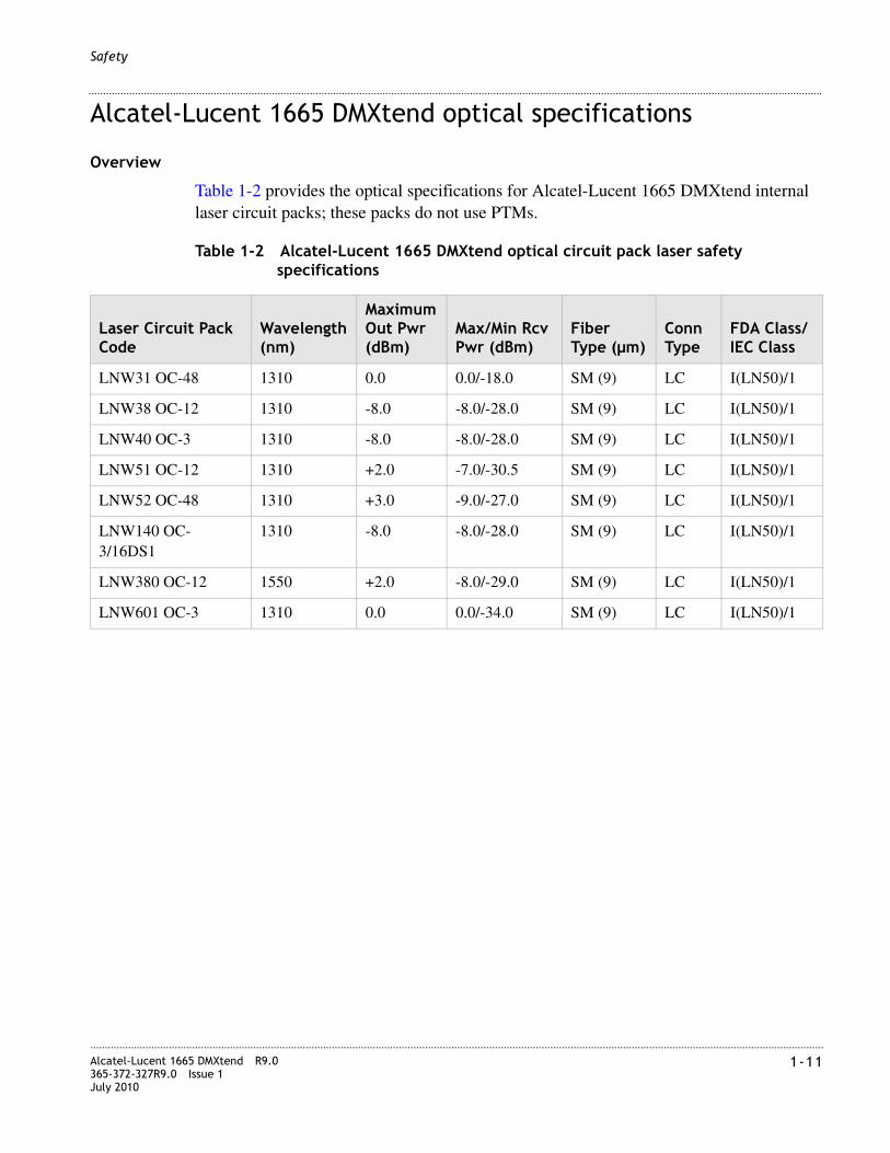
Alcatel-Lucent 1665 DMXtend optical specifications
Overview
Table 1-2 provides the optical specifications for Alcatel-Lucent 1665 DMXtend internal laser circuit packs; these packs do not use PTMs.
Table 1-2 Alcatel-Lucent 1665 DMXtend optical circuit pack laser safety specifications
Laser Circuit Pack Code
Wavelength (nm)
Maximum Out Pwr (dBm)
Max/Min Rcv Pwr (dBm)
Fiber Type (µm)
Conn Type
FDA Class/IEC Class
LNW31 OC-48 1310 0.0 0.0/-18.0 SM (9) LC I(LN50)/1
LNW38 OC-12 1310 -8.0 -8.0/-28.0 SM (9) LC I(LN50)/1
LNW40 OC-3 1310 -8.0 -8.0/-28.0 SM (9) LC I(LN50)/1
LNW51 OC-12 1310 +2.0 -7.0/-30.5 SM (9) LC I(LN50)/1
LNW52 OC-48 1310 +3.0 -9.0/-27.0 SM (9) LC I(LN50)/1
LNW140 OC- 3/16DS1
1310 -8.0 -8.0/-28.0 SM (9) LC I(LN50)/1
LNW380 OC-12 1550 +2.0 -8.0/-29.0 SM (9) LC I(LN50)/1
LNW601 OC-3 1310 0.0 0.0/-34.0 SM (9) LC I(LN50)/1

............................................................................................................................................................................................................................................................1-12 Alcatel-Lucent 1665 DMXtend R9.0
365-372-327R9.0 Issue 1July 2010
............................................................................................................................................................................................................................................................
Safety
Table 1-3 shows the pluggable transmission module (PTM) laser safety specifications and the supported circuit packs. The following Class 1 SFP/XFP transceivers are Alcatel-Lucent approved.
Table 1-3 Alcatel-Lucent 1665 DMXtend optical PTM laser safety specifications
Module Code
Supported Circuit Pack(s)
Wavelength (nm)
Maximum Out Pwr (dBm)
Max/Min Rcv Pwr (dBm)
Fiber Type (µm)
Conn Type
FDA Class/IEC Class
100BASE-ZX-I1
LNW74LNW87LNW170
1550 +2.0 -8.0/-31.0 SM (9) LC I(LN50)/1
100BASE-LX-L1
LNW74LNW87LNW170
1310 -8.0 -8.0/-25.0 SM (9) LC I(LN50)/1
100BASE-FX-I1
LNW74LNW87LNW170
1310 -14.0 -14.0/-29.0 MM (50 and 62.5)
LC I(LN50)/1
1000BASE-ZX-I1
LNW63LNW64LNW74LNW87LNW170
1550 +5.0 0.0/-22.5 SM (9) LC I(LN50)/1
1000BASE-LX-I1
LNW63LNW64LNW87LNW170
1310 -3.0 -3.0/-19.0 SM (9) LC I(LN50)/1
1000BASE-SX-I1
LNW63LNW64LNW87LNW170
850 0.0 0.0/-19.0 MM (50 and 62.5)
LC I(LN50)/1
BASE-TC1-electrical
LNW63LNW64LNW87LNW170
NA NA NA NA RJ45 NA
ESCON-MM-I1
LNW73/73C 1310 -14.0 -14.4/-29.0 MM (50 and 62.5)
LC I(LN50)/1
GE-1X2XFC-LX-C1
LNW64LNW73/73CLNW87LNW170
1310 -3.0 -3.0/-19.0 SM (9) LC I(LN50)/1
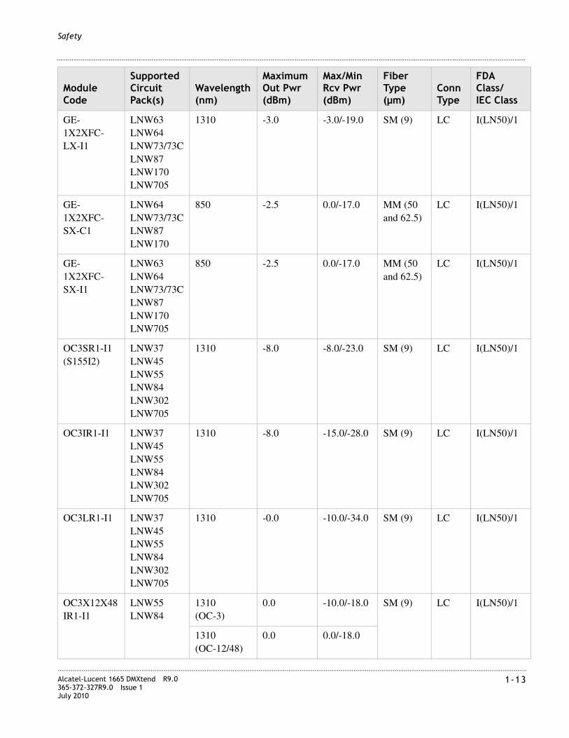
............................................................................................................................................................................................................................................................Alcatel-Lucent 1665 DMXtend R9.0365-372-327R9.0 Issue 1July 2010
1-13
............................................................................................................................................................................................................................................................
Safety
GE-1X2XFC-LX-I1
LNW63LNW64 LNW73/73CLNW87LNW170LNW705
1310 -3.0 -3.0/-19.0 SM (9) LC I(LN50)/1
GE-1X2XFC-SX-C1
LNW64LNW73/73CLNW87LNW170
850 -2.5 0.0/-17.0 MM (50 and 62.5)
LC I(LN50)/1
GE-1X2XFC-SX-I1
LNW63LNW64LNW73/73CLNW87LNW170LNW705
850 -2.5 0.0/-17.0 MM (50 and 62.5)
LC I(LN50)/1
OC3SR1-I1 (S155I2)
LNW37LNW45LNW55LNW84LNW302LNW705
1310 -8.0 -8.0/-23.0 SM (9) LC I(LN50)/1
OC3IR1-I1 LNW37LNW45LNW55LNW84LNW302LNW705
1310 -8.0 -15.0/-28.0 SM (9) LC I(LN50)/1
OC3LR1-I1 LNW37LNW45LNW55LNW84LNW302LNW705
1310 -0.0 -10.0/-34.0 SM (9) LC I(LN50)/1
OC3X12X48IR1-I1
LNW55LNW84
1310 (OC-3)
0.0 -10.0/-18.0 SM (9) LC I(LN50)/1
1310 (OC-12/48)
0.0 0.0/-18.0
Module Code
Supported Circuit Pack(s)
Wavelength (nm)
Maximum Out Pwr (dBm)
Max/Min Rcv Pwr (dBm)
Fiber Type (µm)
Conn Type
FDA Class/IEC Class

............................................................................................................................................................................................................................................................1-14 Alcatel-Lucent 1665 DMXtend R9.0
365-372-327R9.0 Issue 1July 2010
............................................................................................................................................................................................................................................................
Safety
OC3X12X48LR1-I1
LNW55LNW84
1310(OC-3)
+3.0 -15.0/-2.0 SM (9) LC I(LN50)/1
1310 (OC-12/48)
+3.0 -9.0/-2.0
OC12IR1-I1 LNW49LNW55LNW84LNW382LNW705
1310 -8.0 -8.0/-28.0 SM (9) LC I(LN50)/1
OC12LR1-I1 LNW49LNW55LNW84LNW382LNW705
1310 +2.0 -8.0/-28.0 SM (9) LC I(LN50)/1
OC12LR2-I1 LNW49LNW55LNW84LNW382LNW705
1550 +2.0 -8.0/-28.0 SM (9) LC I(LN50)/1
S622C47EL LNW37LNW45LNW49LNW55LNW84
1471 +5.0 -8.0/-28.0 SM (9) LC I(LN50)/1
S622C49EL LNW37LNW45LNW49LNW55LNW84LNW705
1491 +5.0 -8.0/-28.0 SM (9) LC I(LN50)/1
S622C51EL LNW37LNW45LNW49LNW55LNW84LNW705
1511 +5.0 -8.0/-28.0 SM (9) LC I(LN50)/1
Module Code
Supported Circuit Pack(s)
Wavelength (nm)
Maximum Out Pwr (dBm)
Max/Min Rcv Pwr (dBm)
Fiber Type (µm)
Conn Type
FDA Class/IEC Class

............................................................................................................................................................................................................................................................Alcatel-Lucent 1665 DMXtend R9.0365-372-327R9.0 Issue 1July 2010
1-15
............................................................................................................................................................................................................................................................
Safety
S622C53EL LNW37LNW45LNW49LNW55LNW84LNW705
1531 +5.0 -8.0/-28.0 SM (9) LC I(LN50)/1
S622C55EL LNW37LNW45LNW49LNW55LNW84LNW705
1551 +5.0 -8.0/-28.0 SM (9) LC I(LN50)/1
S622C57EL LNW37LNW45LNW49LNW55LNW84LNW705
1571 +5.0 -8.0/-28.0 SM (9) LC I(LN50)/1
S622C59EL LNW37LNW45LNW49LNW55LNW84LNW705
1591 +5.0 -8.0/-28.0 SM (9) LC I(LN50)/1
S622C61EL LNW37LNW45LNW49LNW55LNW84LNW705
1611 +5.0 -8.0/-28.0 SM (9) LC I(LN50)/1
OC48SR1-I1 LNW41LNW55LNW62LNW84LNW402LNW705
1310 -3.0 -3.0/-18.0 SM (9) LC I(LN50)/1
Module Code
Supported Circuit Pack(s)
Wavelength (nm)
Maximum Out Pwr (dBm)
Max/Min Rcv Pwr (dBm)
Fiber Type (µm)
Conn Type
FDA Class/IEC Class

............................................................................................................................................................................................................................................................1-16 Alcatel-Lucent 1665 DMXtend R9.0
365-372-327R9.0 Issue 1July 2010
............................................................................................................................................................................................................................................................
Safety
OC48LR1-I1 LNW41LNW55LNW62LNW84LNW402LNW705
1310 +3.0 -9.0/-27.0 SM (9) LC I(LN50)/1
OC48LR2-I1 LNW41LNW55LNW62LNW84LNW402LNW705
1550 +3.0 -9.0/-28.0 SM (9) LC I(LN50)/1
S155I2 (OC3SR1-I1)
LNW41LNW55LNW62LNW84LNW302LNW705
1310 -8.0 -8.0/-23.0 SM (9) LC I(LN50)/1
S2D23C6 LNW41LNW55LNW62LNW84LNW402
1558.983 +4.0 -9.0/-28.0 SM (9) LC I(LN50)/1
S2D25C6 LNW41LNW55LNW62LNW84LNW402
1557.363 +4.0 -9.0/-28.0 SM (9) LC I(LN50)/1
S2D27C6 LNW41LNW55LNW62LNW84LNW402
1555.747 +4.0 -9.0/-28.0 SM (9) LC I(LN50)/1
Module Code
Supported Circuit Pack(s)
Wavelength (nm)
Maximum Out Pwr (dBm)
Max/Min Rcv Pwr (dBm)
Fiber Type (µm)
Conn Type
FDA Class/IEC Class
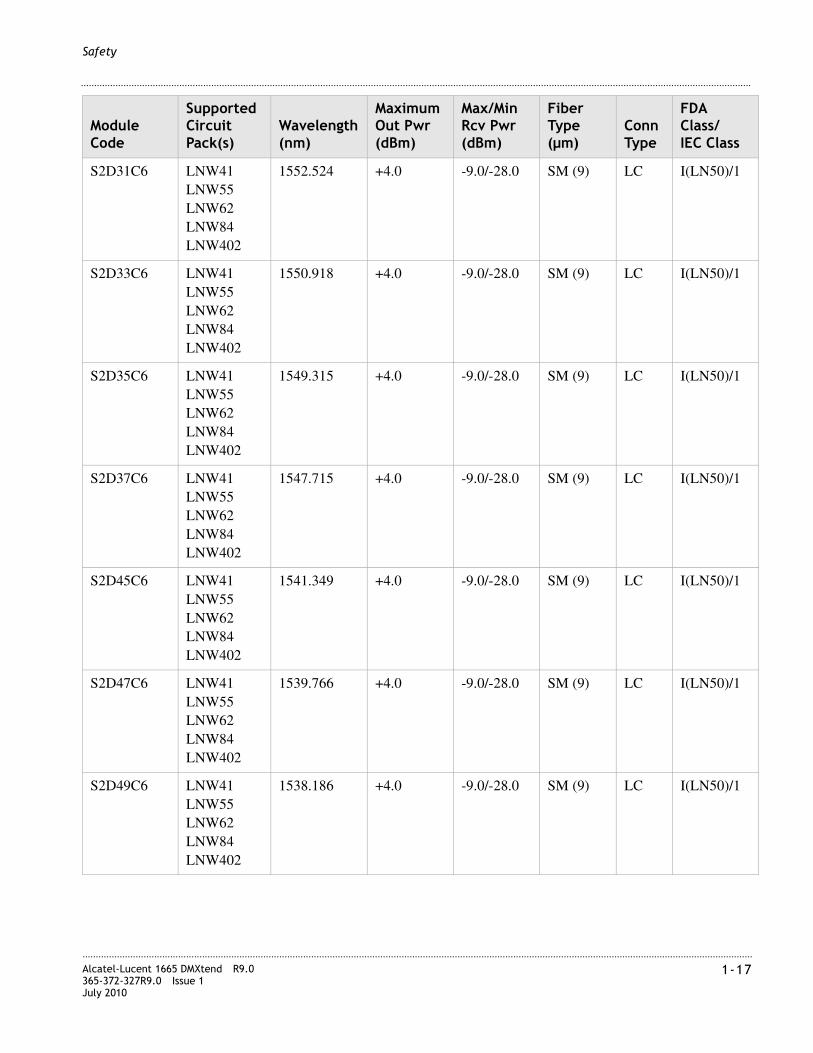
............................................................................................................................................................................................................................................................Alcatel-Lucent 1665 DMXtend R9.0365-372-327R9.0 Issue 1July 2010
1-17
............................................................................................................................................................................................................................................................
Safety
S2D31C6 LNW41LNW55LNW62LNW84LNW402
1552.524 +4.0 -9.0/-28.0 SM (9) LC I(LN50)/1
S2D33C6 LNW41LNW55LNW62LNW84LNW402
1550.918 +4.0 -9.0/-28.0 SM (9) LC I(LN50)/1
S2D35C6 LNW41LNW55LNW62LNW84LNW402
1549.315 +4.0 -9.0/-28.0 SM (9) LC I(LN50)/1
S2D37C6 LNW41LNW55LNW62LNW84LNW402
1547.715 +4.0 -9.0/-28.0 SM (9) LC I(LN50)/1
S2D45C6 LNW41LNW55LNW62LNW84LNW402
1541.349 +4.0 -9.0/-28.0 SM (9) LC I(LN50)/1
S2D47C6 LNW41LNW55LNW62LNW84LNW402
1539.766 +4.0 -9.0/-28.0 SM (9) LC I(LN50)/1
S2D49C6 LNW41LNW55LNW62LNW84LNW402
1538.186 +4.0 -9.0/-28.0 SM (9) LC I(LN50)/1
Module Code
Supported Circuit Pack(s)
Wavelength (nm)
Maximum Out Pwr (dBm)
Max/Min Rcv Pwr (dBm)
Fiber Type (µm)
Conn Type
FDA Class/IEC Class

............................................................................................................................................................................................................................................................1-18 Alcatel-Lucent 1665 DMXtend R9.0
365-372-327R9.0 Issue 1July 2010
............................................................................................................................................................................................................................................................
Safety
S2D53C6 LNW41LNW55LNW62LNW84LNW402
1535.036 +4.0 -9.0/-28.0 SM (9) LC I(LN50)/1
S2D55C6 LNW41LNW55LNW62LNW84LNW402
1533.465 +4.0 -9.0/-28.0 SM (9) LC I(LN50)/1
S2D59C6 LNW41LNW55LNW62LNW84LNW402
1530.334 +4.0 -9.0/-28.0 SM (9) LC I(LN50)/1
S2G7C47LI LNW41LNW55LNW62LNW84LNW402
1471 +5.0 -8.0/NA SM (9) LC I(LN50)/1
S2G7C49LI LNW41LNW55LNW62LNW84LNW402
1491 +5.0 -8.0/NA SM (9) LC I(LN50)/1
S2G7C51LI LNW41LNW55LNW62LNW84LNW402
1511 +5.0 -8.0/NA SM (9) LC I(LN50)/1
S2G7C53LI LNW41LNW55LNW62LNW84LNW402
1531 +5.0 -8.0/NA SM (9) LC I(LN50)/1
Module Code
Supported Circuit Pack(s)
Wavelength (nm)
Maximum Out Pwr (dBm)
Max/Min Rcv Pwr (dBm)
Fiber Type (µm)
Conn Type
FDA Class/IEC Class

............................................................................................................................................................................................................................................................Alcatel-Lucent 1665 DMXtend R9.0365-372-327R9.0 Issue 1July 2010
1-19
............................................................................................................................................................................................................................................................
Safety
S2G7C55LI LNW41LNW55LNW62LNW84LNW402
1551 +5.0 -8.0/NA SM (9) LC I(LN50)/1
S2G7C57LI LNW41LNW55LNW62LNW84LNW402
1571 +5.0 -8.0/NA SM (9) LC I(LN50)/1
S2G7C59LI LNW41LNW55LNW62LNW84LNW402
1591 +5.0 -8.0/NA SM (9) LC I(LN50)/1
S2G7C61LI LNW41LNW55LNW62LNW84LNW402
1611 +5.0 -8.0/NA SM (9) LC I(LN50)/1
OC192IR2-I1
LNW141LNW705
1550 +2.0 -7.0/-24.0 SM (9) LC I(LN50)/1
X10G21C5 LNW141 1560.606 +3.0 -8.0/Table 1-4
SM (9) LC I(LN50)/1
X10G22C5 LNW141 1559.794 +3.0 -8.0/Table 1-4
SM (9) LC I(LN50)/1
X10G23C5 LNW141 1558.983 +3.0 -8.0/Table 1-4
SM (9) LC I(LN50)/1
X10G24C5 LNW141 1558.173 +3.0 -8.0/Table 1-4
SM (9) LC I(LN50)/1
X10G25C5 LNW141 1557.363 +3.0 -8.0/Table 1-4
SM (9) LC I(LN50)/1
Module Code
Supported Circuit Pack(s)
Wavelength (nm)
Maximum Out Pwr (dBm)
Max/Min Rcv Pwr (dBm)
Fiber Type (µm)
Conn Type
FDA Class/IEC Class

............................................................................................................................................................................................................................................................1-20 Alcatel-Lucent 1665 DMXtend R9.0
365-372-327R9.0 Issue 1July 2010
............................................................................................................................................................................................................................................................
Safety
X10G26C5 LNW141 1556.555 +3.0 -8.0/Table 1-4
SM (9) LC I(LN50)/1
X10G27C5 LNW141 1555.747 +3.0 -8.0/Table 1-4
SM (9) LC I(LN50)/1
X10G28C5 LNW141 1554.940 +3.0 -8.0/Table 1-4
SM (9) LC I(LN50)/1
X10G31C5 LNW141LNW705
1552.524 +3.0 -8.0/Table 1-4
SM (9) LC I(LN50)/1
X10G33C5 LNW141LNW705
1550.918 +3.0 -8.0/Table 1-4
SM (9) LC I(LN50)/1
X10G35C5 LNW141LNW705
1549.315 +3.0 -8.0/Table 1-4
SM (9) LC I(LN50)/1
X10G37C5 LNW141LNW705
1547.715 +3.0 -8.0/Table 1-4
SM (9) LC I(LN50)/1
X10G45C5 LNW141LNW705
1541.349 +3.0 -8.0/Table 1-4
SM (9) LC I(LN50)/1
X10G47C5 LNW141LNW705
1539.766 +3.0 -8.0/Table 1-4
SM (9) LC I(LN50)/1
X10G49C5 LNW141LNW705
1538.186 +3.0 -8.0/Table 1-4
SM (9) LC I(LN50)/1
X10G52C5 LNW141 1535.822 +3.0 -8.0/Table 1-4
SM (9) LC I(LN50)/1
X10G53C5 LNW141 1535.036 +3.0 -8.0/Table 1-4
SM (9) LC I(LN50)/1
Module Code
Supported Circuit Pack(s)
Wavelength (nm)
Maximum Out Pwr (dBm)
Max/Min Rcv Pwr (dBm)
Fiber Type (µm)
Conn Type
FDA Class/IEC Class

............................................................................................................................................................................................................................................................Alcatel-Lucent 1665 DMXtend R9.0365-372-327R9.0 Issue 1July 2010
1-21
............................................................................................................................................................................................................................................................
Safety
Table 1-4 Dispersion-limited receiver sensitivity for OC-192 DWDM PTMs
X10G54C5 LNW141 1534.250 +3.0 -8.0/Table 1-4
SM (9) LC I(LN50)/1
X10G55C5 LNW141 1533.465 +3.0 -8.0/Table 1-4
SM (9) LC I(LN50)/1
X10G56C5 LNW141 1532.681 +3.0 -8.0/Table 1-4
SM (9) LC I(LN50)/1
X10G57C5 LNW141 1531.898 +3.0 -8.0/Table 1-4
SM (9) LC I(LN50)/1
X10G58C5 LNW141 1531.116 +3.0 -8.0/Table 1-4
SM (9) LC I(LN50)/1
X10G59C5 LNW141 1530.334 +3.0 -8.0/Table 1-4
SM (9) LC I(LN50)/1
Module Code
Supported Circuit Pack(s)
Wavelength (nm)
Maximum Out Pwr (dBm)
Max/Min Rcv Pwr (dBm)
Fiber Type (µm)
Conn Type
FDA Class/IEC Class
Data Rate
Receiver Sensitivity 0 ps/nm dispersion
Receiver Sensitivity 1300 ps/nm dispersion
Receiver Sensitivity 1600 ps/nm dispersion
9.9 Gb/s -24.0 dBm -22.0 dBm NA
10.7-11.1 Gb/s with Forward Error Correction (FEC) enabled
-27.0 dBm NA -25.0 dBm

............................................................................................................................................................................................................................................................1-22 Alcatel-Lucent 1665 DMXtend R9.0
365-372-327R9.0 Issue 1July 2010
............................................................................................................................................................................................................................................................
Safety

I-1Alcatel-Lucent 1665 DMXtend R9.0365-372-327R9.0 Issue 1July 2010
............................................................................................................................................................................................................................................................
Part I: Physical and power installation
Overview
Introduction
Part I covers the physical mounting of the Alcatel-Lucent 1665 Data Multiplexer Extend (Alcatel-Lucent 1665 DMXtend) shelf using the Horizontal Bay Mount. This section includes running and connecting power cables, interconnecting cables, alarm cables, and as required, external timing, and communication cables. Initial circuit pack installation (not seated) is also included.
Part I provides a recommended checklist Table I-2 “Installation checklist” to follow when installing Alcatel-Lucent 1665 DMXtend. Use of the installation checklist is required to ensure a quality installation. All completed tasks should be checked off and those not completed should be duly noted as to the reason why. This checklist should be turned in as part of your job complete paperwork.
Note: The Alcatel-Lucent 1665 DMXtend shelf does not require the installation of an additional fan shelf since the fan unit is integral to the shelf itself.
Contents
This part includes the following chapters:
Chapter 2, “Physical installation”
Chapter 3, “Cable and fiber installation”
Chapter 4, “Circuit pack installation”

............................................................................................................................................................................................................................................................I-2 Alcatel-Lucent 1665 DMXtend R9.0
365-372-327R9.0 Issue 1July 2010
............................................................................................................................................................................................................................................................
Physical and power installation
Tools, test equipment and accessories
This section lists the tools, test equipment and accessories needed to perform all the procedures in this installation manual.
Listed below are the required tools, test equipment and accessories.
Qty. Description Comments
1 19" Mounting Brackets849011804
The 19" mounting brackets (C849011804) must be ordered separately and are required to install the Alcatel-Lucent 1665 DMXtend in a 19" bayframe.
Screwdriver(s) A screwdriver(s) with the appropriate head(s) is (are) required for securing the mounting screws, repositioning the mounting brackets, installing the interfacing cables, and for setting the circuit breakers to the OFF position.
1 Thomas & Betts* R-5648B Crimping Tool
The crimping tool and wire stripper are only required if installing DS3/EC1 cables. The replacement cassette is for the wire stripper tool.
2 Paladin† Coaxial Wire Stripper R-5648B
Replacement Paladin† Cassette R-5648B D5
1 Wire-Wrap Gun
R-4496A
The wire-wrap gun is required for terminating DS1/E1 cable and must be able to accommodate 24 gauge wire.
1 ESD Wrist Strap
R-4987C
A wrist strap must be worn when handling circuit packs. Use the electrostatic discharge (ESD) jack provided on the shelf.
1 Torque Wrench
R-5952
A torque wrench (50-250 IN-LBS) is used when tightening the Alcatel-Lucent 1665 DMXtend shelf to the frame. It is also used when reattaching the mounting brackets to the Alcatel-Lucent 1665 DMXtend shelf.
1 Metric & Inch Series Tool Set
R-6001
Because some of our Optical Networking Products (also know as Transport) may have some metric fasteners, please ensure that the proper metric tools are available.
1 Multimeter (Optional)
ITE-6379C
The voltmeter must be capable of measuring DC voltage in the 40 to 60 volt range. The use of the voltmeter is optional since the shelf will alarm or shut down if the proper voltage is not supplied.

............................................................................................................................................................................................................................................................Alcatel-Lucent 1665 DMXtend R9.0365-372-327R9.0 Issue 1July 2010
I-3
............................................................................................................................................................................................................................................................
Physical and power installation
1 Ohmmeter
ITE-6379C
An ohmmeter is required to verify that the Alcatel-Lucent 1665 DMXtend is properly grounded.
1 DS1/E1 Error Rate Test Set
ITE-7113
A DS1/E1 error rate test set is required for testing of DS1/E1 cabling. A T-BERD 2209 or equivalent is recommended.
1 DS3/EC1 Error Rate Test Set
ITE-7113
A DS3/EC1 error rate test set is required for testing of DS3/EC1 cabling. A T-BERD 209 or equivalent is recommended.
1 Optical Test Set (Optional) A Optical test set is required for testing of low speed optics OC3/12/48. An Omniber 718 or equivalent is recommended.
2 or 3 LC-type Optical Fiber Jumper ITE-7169 (108918269)
Two optical fiber jumpers with LC type connectors are required to optically loop the Alcatel-Lucent 1665 DMXtend shelf for test purposes. In addition, for shelves containing optical circuit packs in any of the function unit slots, a single optical fiber jumper is required for testing of the individual ports.
1 15-dB LC-type LBO ITE-7196 (108279480)
LBOs are only required when optically looping the Alcatel-Lucent 1665 DMXtend shelves containing optical circuit packs in any of the function unit slots; a single 15-dB LBO is required for testing of the individual ports
Noyes OFS 300-200X Optical Fiber Scope
ITE-7129
This equipment may not be necessary at all locations. It is to be used when the ports need to be verified for cleanliness. If care is exercised when cleaning fibers, the optical fiber scope may not be needed
2.5mm Universal adapter cap ITE-7129 D1
For use with the Noyes OFS 300-200X Optical Fiber Scope
1.25mm Universal adapter cap ITE-7129 D2
Noyes VFS-1 ITE-7187 Video Fiber Scope1
This equipment may not be necessary at all locations. It is to be used when the ports need to be verified for cleanliness. If care is exercised when cleaning fibers, the video scope may not be needed
Individual presaturated alcohol wipes ITE-7136
99% pure isopropyl alcohol
Qty. Description Comments
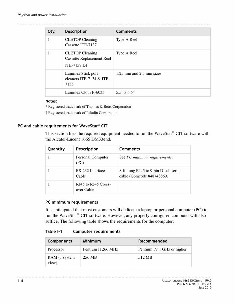
............................................................................................................................................................................................................................................................I-4 Alcatel-Lucent 1665 DMXtend R9.0
365-372-327R9.0 Issue 1July 2010
............................................................................................................................................................................................................................................................
Physical and power installation
PC and cable requirements for WaveStar® CIT
This section lists the required equipment needed to run the WaveStar® CIT software with the Alcatel-Lucent 1665 DMXtend.
PC minimum requirements
It is anticipated that most customers will dedicate a laptop or personal computer (PC) to run the WaveStar® CIT software. However, any properly configured computer will also suffice. The following table shows the requirements for the computer:
Table I-1 Computer requirements
1 CLETOP Cleaning Cassette ITE-7137
Type A Reel
1 CLETOP Cleaning Cassette Replacement Reel
ITE-7137 D1
Type A Reel
Luminex Stick port cleaners ITE-7134 & ITE-7135
1.25 mm and 2.5 mm sizes
Luminex Cloth R-6033 5.5” x 5.5”
Notes:* Registered trademark of Thomas & Betts Corporation
† Registered trademark of Paladin Corporation.
Qty. Description Comments
Quantity Description Comments
1 Personal Computer (PC)
See PC minimum requirements.
1 RS-232 Interface Cable
8-ft. long RJ45 to 9-pin D-sub serial cable (Comcode 848748869)
1 RJ45 to RJ45 Cross-over Cable
Components Minimum Recommended
Processor Pentium II 266 MHz Pentium IV 1 GHz or higher
RAM (1 system view)
256 MB 512 MB

............................................................................................................................................................................................................................................................Alcatel-Lucent 1665 DMXtend R9.0365-372-327R9.0 Issue 1July 2010
I-5
............................................................................................................................................................................................................................................................
Physical and power installation
Note: Minimum requirements are sufficient to run two to three GUI System Views, unless otherwise noted. Recommended requirements are intended to be used as a general guideline to optimize WaveStar® CIT performance. As the CIT is used with multiple NE connections and multiple NE types, the processor type, speed and memory size will all factor into CIT performance.
RAM (up to 5 system views)
256 MB 1 GB
Virtual Memory 139 MB 267 MB
Available Hard Disk Space*
750 MB (Alcatel-Lucent 1665 DMXtend view only)
850 MB (for all graphical packages)
Video 800X600 256 Colors(8 bit)
1024X768 16 Million Colors (24 bit)
Network Interface 10/100 baseT Network Card
10/100 BASE-T LAN interface Pin Designations/signals are:
• 1 TD+
• 2 TD-
• 3 RD+
• 6 RD-
CD ROM Drive Required
Operating System Microsoft Windows® 2000 or Microsoft Windows® XP
The customer is responsible for ensuring that the PC remains virus-free.
Internet Browser Internet Explorer5.0/5.5/6.0/7.0
Internet Explorer5.0/5.5/6.0/7.0
Notes:* Available hard disk space required to install and store the CIT and Generic Software isapproximately 250 MB (it is 550 MB, if all graphical packages are installed). The additional diskspace specified is to provide hard disk space to store Alcatel-Lucent 1665 DMXtend backupfiles.
Components Minimum Recommended

............................................................................................................................................................................................................................................................I-6 Alcatel-Lucent 1665 DMXtend R9.0
365-372-327R9.0 Issue 1July 2010
............................................................................................................................................................................................................................................................
Physical and power installation
Table I-2 Installation checklist
Section and chapter Procedure Required
Completed
Yes No
Part I: “Physical and power installation”
Chapter 2, “Physical installation”
Inspection (p. 2-5) Yes
Alcatel-Lucent 1665 DMXtend center divider (p. 2-5)
See Note 1
Alcatel-Lucent 1665 DMXtend shelf installation (p. 2-8)
Yes
Power cable installation (p. 2-13) Yes
Chapter 3, “Cable and fiber installation”
Inspection (p. 3-5) Yes
DS1/E1 cable installation (p. 3-6) See Note 1
DS3/EC-1 cable installation (p. 3-13) See Note 1
DS1 and DS3 hybrid cable installation (p. 3-32) See Note 1
10/100BASE-T Ethernet cable installation (p. 3-40)
See Note 1
IAO LAN and TCP/IP cable installation (p. 3-44)
See Note 1
Modem cable installation (p. 3-47) See Note 1
Sync cable installation (p. 3-49) See Note 1
Office alarm cable installation (p. 3-53) See Note 1
Miscellaneous (environmental) discrete telemetry cable installation (p. 3-58)
See Note 1
OC-3/OC-12/OC-48/OC-192 main optical fiber cable installation (p. 3-62)
See Note 1
OC-3/OC-12/OC-48 low-speed optical fiber cable installation (p. 3-65)
See Note 1
100/1000BASE-X optical fiber cable installation (p. 3-66)
See Note 1
CIT (RS-232) cable installation (p. 3-68) See Note 1
Final operations (p. 3-70) Yes
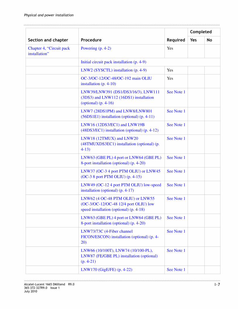
............................................................................................................................................................................................................................................................Alcatel-Lucent 1665 DMXtend R9.0365-372-327R9.0 Issue 1July 2010
I-7
............................................................................................................................................................................................................................................................
Physical and power installation
Chapter 4, “Circuit pack installation”
Powering (p. 4-2) Yes
Initial circuit pack installation (p. 4-9)
LNW2 (SYSCTL) installation (p. 4-9) Yes
OC-3/OC-12/OC-48/OC-192 main OLIU installation (p. 4-10)
Yes
LNW39/LNW391 (DS1/DS3/16/3), LNW111 (3DS3) and LNW112 (16DS1) installation (optional) (p. 4-16)
See Note 1
LNW7 (28DS1PM) and LNW8/LNW801 (56DS1E1) installation (optional) (p. 4-11)
See Note 1
LNW16 (12DS3/EC1) and LNW19B (48DS3/EC1) installation (optional) (p. 4-12)
See Note 1
LNW18 (12TMUX) and LNW20 (48TMUXDS3EC1) installation (optional) (p. 4-13)
See Note 1
LNW63 (GBE PL) 4 port or LNW64 (GBE PL) 8-port installation (optional) (p. 4-20)
See Note 1
LNW37 (OC-3 4 port PTM OLIU) or LNW45 (OC-3 8 port PTM OLIU) (p. 4-15)
See Note 1
LNW49 (OC-12 4 port PTM OLIU) low-speed installation (optional) (p. 4-17)
See Note 1
LNW62 (4 OC-48 PTM OLIU) or LNW55 (OC-3/OC-12/OC-48 12/4 port OLIU) low speed installation (optional) (p. 4-18)
See Note 1
LNW63 (GBE PL) 4 port or LNW64 (GBE PL) 8-port installation (optional) (p. 4-20)
See Note 1
LNW73/73C (4-Fiber channel FICON/ESCON) installation (optional) (p. 4-20)
See Note 1
LNW66 (10/100T), LNW74 (10/100-PL), LNW87 (FE/GBE PL) installation (optional) (p. 4-21)
See Note 1
LNW170 (GigE/FE) (p. 4-22) See Note 1
Section and chapter Procedure Required
Completed
Yes No

............................................................................................................................................................................................................................................................I-8 Alcatel-Lucent 1665 DMXtend R9.0
365-372-327R9.0 Issue 1July 2010
............................................................................................................................................................................................................................................................
Physical and power installation
LNW402 OC48 1310 nm, 1550 nm, or DWDM PTM Optics (p. 4-23)
See Note 1
LNW63 (GBE PL) 4 port or LNW64 (GBE PL) 8-port installation (optional) (p. 4-20)
See Note 1
LNW785 OMD5/8 8-channel low-loss DWDM optical mux/demux (p. 4-25)
See Note 1
LNW43, LNW96 (apparatus blank) installation (optional) (p. 4-26)
See Note 1
LNW42, LNW95 apparatus blank installation (optional) (p. 4-27)
See Note 1
Notes: 1. Only required if equipped.
Section and chapter Procedure Required
Completed
Yes No

2-1Alcatel-Lucent 1665 DMXtend R9.0365-372-327R9.0 Issue 1July 2010
............................................................................................................................................................................................................................................................
2 Physical installation
Overview
Purpose
This section provides equipment installation instructions for the Alcatel-Lucent 1665 Data Multiplexer Extend (Alcatel-Lucent 1665 DMXtend) shelf using the horizontal bay mount configuration. The Alcatel-Lucent 1665 DMXtend shelves with the removable center divider can support either half width or full width cards in the Main function slots.
Contents
This chapter provides information on the following topics:
Planning
Description
This section provides information about the following:
• Tools, test equipment and accessories
• Mounting options
• Cabling checklist
Planning 2-1
Inspection 2-5
Alcatel-Lucent 1665 DMXtend center divider 2-5
Alcatel-Lucent 1665 DMXtend shelf installation 2-8
Power cable installation 2-13
Final operations 2-17

............................................................................................................................................................................................................................................................2-2 Alcatel-Lucent 1665 DMXtend R9.0
365-372-327R9.0 Issue 1July 2010
............................................................................................................................................................................................................................................................
Physical installation
Tools, test equipment and accessories
Listed below are the tools, test equipment and accessories necessary to perform the procedures in this section.
Mounting options
The Horizontal Bay Mount mounting brackets on the Alcatel-Lucent 1665 DMXtend are designed to allow for mounting in the following:
• Standard 23-inch wide network bay frames
The recommended network bay frames are the ED-8C500-50 and the ED-8C501-50 (rear access only).
Quantity Description Comments
1 19" Mounting Brackets849011804
The 19" mounting brackets (849011804) must be ordered separately and are required to install the Alcatel-Lucent 1665 DMXtend in a 19" bayframe.
Screwdriver(s) A screwdriver(s) with the appropriate head(s) is (are) required for securing the mounting screws, repositioning the mounting brackets, installing the interfacing cables, and for setting the circuit breakers to the OFF position.
1 ESD Wrist Strap R-4987C A wrist strap must be worn when handling circuit packs. Use the electrostatic discharge (ESD) jack provided on the shelf.
1 Multimeter (Optional) ITE-6379
The voltmeter must be capable of measuring DC voltage in the 40 to 60 volt range. The use of the voltmeter is optional since the shelf will alarm or shut down if the proper voltage is not supplied.
1 Torque Wrench ITE-5952 A torque wrench (50-250 IN-LBS) is used when tightening the Alcatel-Lucent 1665 DMXtend shelf to the frame. It is also used when reattaching the mounting brackets to the Alcatel-Lucent 1665 DMXtend shelf.
1 Metric & Inch Series Tool Set
R - 6001
Because some of our Optical Networking Products (also know as Transport) may have some metric fasteners, please ensure that the proper metric tools are available.
1 Ohmmeter ITE-6379 An ohmmeter is required to verify that the Alcatel-Lucent 1665 DMXtend is properly grounded.

............................................................................................................................................................................................................................................................Alcatel-Lucent 1665 DMXtend R9.0365-372-327R9.0 Issue 1July 2010
2-3
............................................................................................................................................................................................................................................................
Physical installation
• Mounted in 23-inch seismic network bay frame
The ED-8C800-50 and ED-8C801-50 seismic network bay frames are designed for use in all earthquake zones, and in general, do not require top support at the 7-foot level. These frames meet Pacific Bell Equipment Framework Standard PBS-000-102PT.
• 19-inch bay frames
• 23-inch wide EIA-Type bay frames
Rear cover assembly
This section describes the optional rear cover assembly kits for both Alcatel-Lucent 1665 DMXtend shelves, (Bay Mount Kit number 849001060) or Alcatel-Lucent 1665 DMXtend shelves (Shelf mount Kit number 849001367). Both kit assemblies will fit either the 19" or 23" bracket assemblies. Figure 2-1 shows the shelf mount Kit assembly.
Note: The shelves (Shelf mount Kit number 849001367) have four pre-drilled holes in the shelf assembly backplane. If the shelf assembly backplane have the four non-drilled holes, then the bay mount kit (Bay Mount Kit number 849001060) must be used.
Shelf mount rear cover
Figure 2-1 Shelf mount rear cover kit 849001367
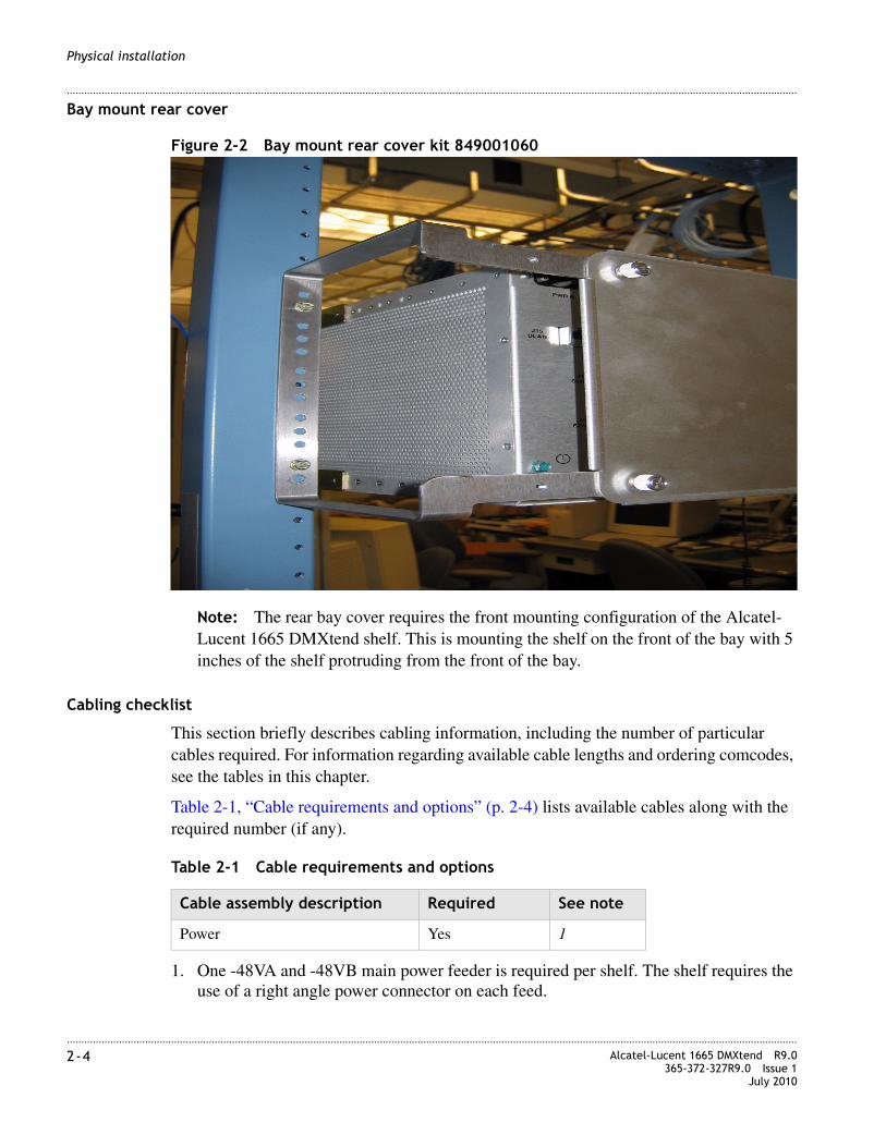
............................................................................................................................................................................................................................................................2-4 Alcatel-Lucent 1665 DMXtend R9.0
365-372-327R9.0 Issue 1July 2010
............................................................................................................................................................................................................................................................
Physical installation
Bay mount rear cover
Figure 2-2 Bay mount rear cover kit 849001060
Note: The rear bay cover requires the front mounting configuration of the Alcatel-Lucent 1665 DMXtend shelf. This is mounting the shelf on the front of the bay with 5 inches of the shelf protruding from the front of the bay.
Cabling checklist
This section briefly describes cabling information, including the number of particular cables required. For information regarding available cable lengths and ordering comcodes, see the tables in this chapter.
Table 2-1, “Cable requirements and options” (p. 2-4) lists available cables along with the required number (if any).
Table 2-1 Cable requirements and options
1. One -48VA and -48VB main power feeder is required per shelf. The shelf requires the use of a right angle power connector on each feed.
Cable assembly description Required See note
Power Yes 1

............................................................................................................................................................................................................................................................Alcatel-Lucent 1665 DMXtend R9.0365-372-327R9.0 Issue 1July 2010
2-5
............................................................................................................................................................................................................................................................
Physical installation
Inspection
Description
Perform the following procedure before installing the Alcatel-Lucent 1665 DMXtend shelf.
Steps
........................................................................................................................................................................................................................
1 Inspect the shelf for visible damage including bent or touching backplane pins.
Note: If any backplane pins are damaged, see Appendix D, “Backplane pin replacement” for instructions on repairing the damaged pin(s).
........................................................................................................................................................................................................................
2 Each Alcatel-Lucent 1665 DMXtend shelf comes with an installation kit. The bag containing the kit is attached inside the Alcatel-Lucent 1665 DMXtend shelf. The kit contains the following items:
Verify that the kit is available and contains the items listed above.
........................................................................................................................................................................................................................
3 Check off the appropriate box in the Table I-2, Installation checklist.
........................................................................................................................................................E N D O F S T E P S
Alcatel-Lucent 1665 DMXtend center divider
Description
The Alcatel-Lucent 1665 DMXtend shelves, comcode 849031372, come shipped with center dividers which can support half-width cards. The center dividers are removed for full-width cards. This section describes the procedure to remove the center dividers on a Alcatel-Lucent 1665 DMXtend shelf if supporting full width cards.
Quantity Description
6 Thread Cutting Screws
1 ESD Jack stud
1 Caution Label
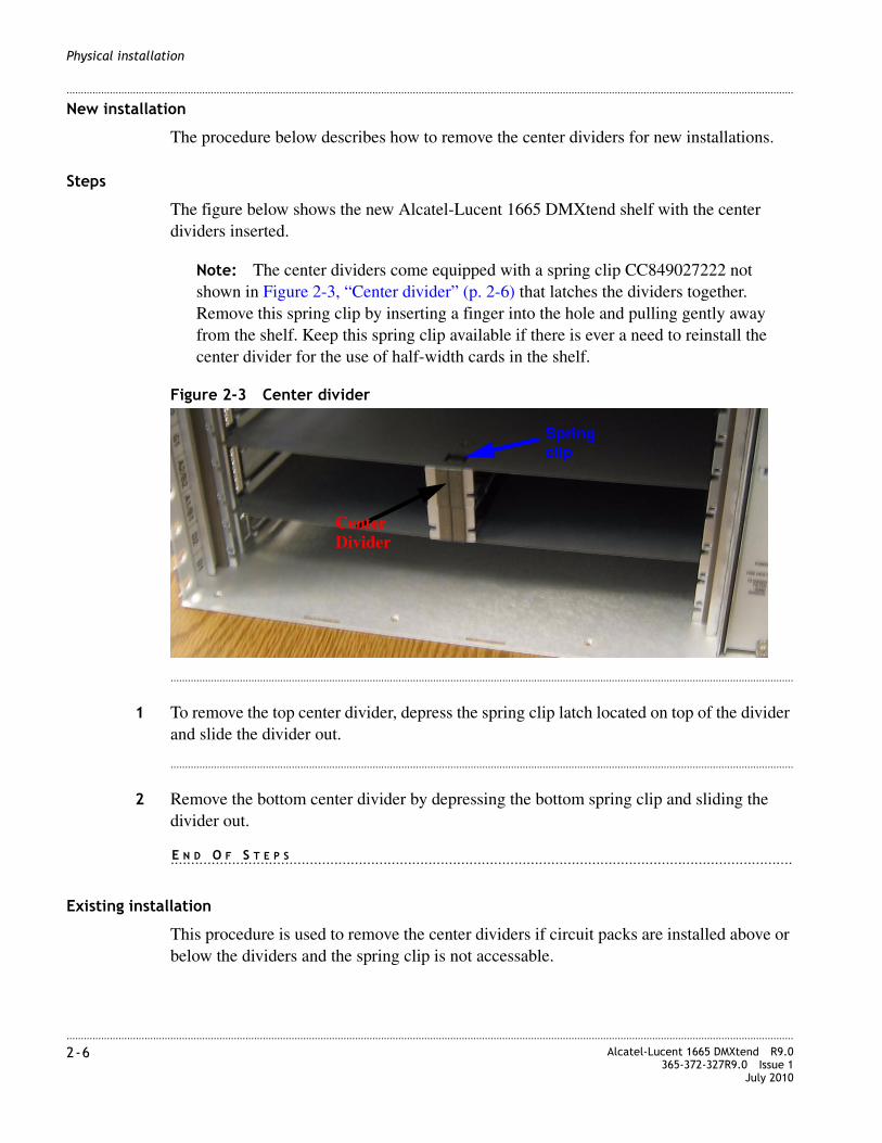
............................................................................................................................................................................................................................................................2-6 Alcatel-Lucent 1665 DMXtend R9.0
365-372-327R9.0 Issue 1July 2010
............................................................................................................................................................................................................................................................
Physical installation
New installation
The procedure below describes how to remove the center dividers for new installations.
Steps
The figure below shows the new Alcatel-Lucent 1665 DMXtend shelf with the center dividers inserted.
Note: The center dividers come equipped with a spring clip CC849027222 not shown in Figure 2-3, “Center divider” (p. 2-6) that latches the dividers together. Remove this spring clip by inserting a finger into the hole and pulling gently away from the shelf. Keep this spring clip available if there is ever a need to reinstall the center divider for the use of half-width cards in the shelf.
Figure 2-3 Center divider
........................................................................................................................................................................................................................
1 To remove the top center divider, depress the spring clip latch located on top of the divider and slide the divider out.
........................................................................................................................................................................................................................
2 Remove the bottom center divider by depressing the bottom spring clip and sliding the divider out.
........................................................................................................................................................E N D O F S T E P S
Existing installation
This procedure is used to remove the center dividers if circuit packs are installed above or below the dividers and the spring clip is not accessable.
CenterDivider
Springclip

............................................................................................................................................................................................................................................................Alcatel-Lucent 1665 DMXtend R9.0365-372-327R9.0 Issue 1July 2010
2-7
............................................................................................................................................................................................................................................................
Physical installation
Steps
The figure below shows the Alcatel-Lucent 1665 DMXtend shelf with both center dividers inserted and a working circuit pack installed above the top divider.
Figure 2-4 Center divider with circuit packs installed.
........................................................................................................................................................................................................................
1 Using a small flat screwdriver, separate the padding as shown in Figure 2-4, “Center divider with circuit packs installed.” (p. 2-7).
........................................................................................................................................................................................................................
2 Insert the screwdriver approximately two thirds of the way up from the bottom of the top divider and depress the latch.
........................................................................................................................................................................................................................
3 Gently slide out the center divider.
........................................................................................................................................................................................................................
4 Repeat for the bottom center divider if necessary. The latch on the bottom divider moves bottom to top.
........................................................................................................................................................E N D O F S T E P S

............................................................................................................................................................................................................................................................2-8 Alcatel-Lucent 1665 DMXtend R9.0
365-372-327R9.0 Issue 1July 2010
............................................................................................................................................................................................................................................................
Physical installation
Alcatel-Lucent 1665 DMXtend shelf installation
Description
As an example of the Alcatel-Lucent 1665 DMXtend shelf installation, the following steps describe mounting the shelf from the front of a 23-inch bay frame. Mounting from the rear of a 23-inch bay frame or from the front/rear of a 19-inch bay frame is similar with the exception of the position of the side brackets.
Positioning of the side brackets is also specified.
Note: This section requires previous bay frame installation and grounding.
Note: If the Alcatel-Lucent 1665 DMXtend shelf is to be used in an outside cabinet with no exchange of outside air, the air filter must be removed.
Steps
........................................................................................................................................................................................................................
1 Position the Alcatel-Lucent 1665 DMXtend shelf on a stable work surface.
........................................................................................................................................................................................................................
2 Open the front cover, remove the installation kit bag, and remove the caution label from the bag.
........................................................................................................................................................................................................................
3 Apply the label to the shelf in a position where it will be visible when the shelf is mounted in the bayframe.
Note: The recommended position is on the left side of the inside of the front cover, but the customer may position it to fit their local practices as long as it is visible when accessing the front of the Alcatel-Lucent 1665 DMXtend shelf.
........................................................................................................................................................................................................................
4 Close and latch the front cover.

............................................................................................................................................................................................................................................................Alcatel-Lucent 1665 DMXtend R9.0365-372-327R9.0 Issue 1July 2010
2-9
............................................................................................................................................................................................................................................................
Physical installation
........................................................................................................................................................................................................................
5 Determine the mounting configuration for the Alcatel-Lucent 1665 DMXtend shelf:
• Type of bay frame (23-inch or 19-inch wide)
• Mounting position (front or rear)
• Position in bay (bottom to top).
Note: The Alcatel-Lucent 1665 DMXtend shelf is shipped with the mounting brackets positioned for mounting to the front of a 23-inch wide network bay frame with a 5 in. setback.
The Alcatel-Lucent 1665 DMXtend shelf mounting brackets may have to be repositioned and remounted, depending on the frame type and mounting position (front or rear).
........................................................................................................................................................................................................................
6 If necessary, reposition the shelf mounting brackets accordingly.
For 23-inch frame, front or rear mounting, see Figure 2-5, “Alcatel-Lucent 1665 DMXtend mounting bracket positions - 23-Inch/19-Inch frame” (p. 2-10).
Note: The 19" mounting brackets (C849011804) must be ordered separately and are required to install the Alcatel-Lucent 1665 DMXtend in a 19" bayframe.
For 19-inch frame, front or rear mounting, see Figure 2-5, “Alcatel-Lucent 1665 DMXtend mounting bracket positions - 23-Inch/19-Inch frame” (p. 2-10).

............................................................................................................................................................................................................................................................2-10 Alcatel-Lucent 1665 DMXtend R9.0
365-372-327R9.0 Issue 1July 2010
............................................................................................................................................................................................................................................................
Physical installation
Figure 2-5 Alcatel-Lucent 1665 DMXtend mounting bracket positions - 23-Inch/19-Inch frame
........................................................................................................................................................................................................................
7 Determine the position that the Alcatel-Lucent 1665 DMXtend shelf will be mounted.
Note: Start at the bottom of the bay and add shelves from bottom to top.
6.0 in.
5.0 in.
8.0 in.
Front Mount Left Side
Front Mount Left Side
Rear Mount Left Side
Front
Front
Front

............................................................................................................................................................................................................................................................Alcatel-Lucent 1665 DMXtend R9.0365-372-327R9.0 Issue 1July 2010
2-11
............................................................................................................................................................................................................................................................
Physical installation
Fiber duct
This section will describe how to install an optional fiber duct.
Note: If a fiber duct is being used to diversify fiber, a 1-inch space is required to accommodate the duct below the existing Alcatel-Lucent 1665 DMXtend. Use the Assembly Fiber Duct kit drawing 848949152 to attach the duct to the Alcatel-Lucent 1665 DMXtend. See Figure 2-6, “Fiber duct mounting” (p. 2-11).
Figure 2-6 Fiber duct mounting
........................................................................................................................................................................................................................
8 Position the Alcatel-Lucent 1665 DMXtend shelf in the frame and secure the shelf to the frame using the thread-forming screws included with the shelf (3 screws per side). Tighten the screws to 21 in.-lb. (minimum)/30 in.-lb. (maximum).
Note: There is a jumper on the fan controller board, at the corner closest to the top-rear of the chassis as installed. It is labeled "FILT BLK" and the two positions are "ENABLE" and "DISABLE." The fan ships with the jumper in the disable position which prevents the filter alarm from working. To enable the filter alarm, move the jumper to the "ENABLE" position. This is the only jumper on the board. The OSP cabinet must be engineered so that the Alcatel-Lucent 1665 DMXtend does not impede air flow to other equipment in the cabinet. The OSP cabinet must be engineered to provide a two inch open space on the left and right sides of the Alcatel-Lucent 1665 DMXtend for air flow. Mounting frame and flanges may intrude on this space.
Note: Be sure to mount the shelf using the thread-forming screws provided with the shelf to ensure a solid ground connection from the bay to the shelf.
Note: For bays that use power coat paint e.g., most 19" bays, studies on that type of paint indicate that the material is not always removed cleanly using the thread forming screws and can create a poor ground, thus we recommend a secondary ground be used.

............................................................................................................................................................................................................................................................2-12 Alcatel-Lucent 1665 DMXtend R9.0
365-372-327R9.0 Issue 1July 2010
............................................................................................................................................................................................................................................................
Physical installation
The secondary ground would consist of a 12 AWG wire from the UL (Green M5 Screw) safety ground on the lower left side of the rear of the shelf to the bayframe (where the bayframe has been scraped clean of paint and treated with no-ox) or directly to the office ground. See Figure 2-7, “Safety ground screw.” (p. 2-12).
Figure 2-7 Safety ground screw.
........................................................................................................................................................................................................................
9 Mount the ESD Jack Stud on the rear of the bayframe where it will be accessible when accessing the rear of the shelf.
........................................................................................................................................................................................................................
10 If fiber spools are to be used, attach the spools to the Alcatel-Lucent 1665 DMXtend using the Fiber Spool Bracket Kit drawing 848949152. Attach the bracket to the shelf first and then the top fiber spool to the bracket. The lower fiber spool will need to overlap the top spool to snap into place. Run the excess fiber per office practices around the spools to minimize the bend radius. See Figure 2-8, “Fiber spools” (p. 2-13).
........................................................................................................................................................................................................................
11 If Alcatel-Lucent fiber ducts are used, see Figure 2-8, “Fiber spools” (p. 2-13). All high-speed fibers are to be run in the duct closest to the shelf for both left and right ducts. The next two ducts away from the shelf are for low-speed fibers.
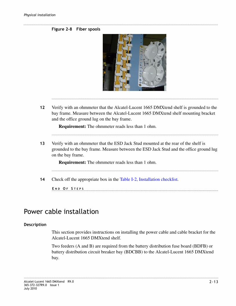
............................................................................................................................................................................................................................................................Alcatel-Lucent 1665 DMXtend R9.0365-372-327R9.0 Issue 1July 2010
2-13
............................................................................................................................................................................................................................................................
Physical installation
Figure 2-8 Fiber spools
........................................................................................................................................................................................................................
12 Verify with an ohmmeter that the Alcatel-Lucent 1665 DMXtend shelf is grounded to the bay frame. Measure between the Alcatel-Lucent 1665 DMXtend shelf mounting bracket and the office ground lug on the bay frame.
Requirement: The ohmmeter reads less than 1 ohm.
........................................................................................................................................................................................................................
13 Verify with an ohmmeter that the ESD Jack Stud mounted at the rear of the shelf is grounded to the bay frame. Measure between the ESD Jack Stud and the office ground lug on the bay frame.
Requirement: The ohmmeter reads less than 1 ohm.
........................................................................................................................................................................................................................
14 Check off the appropriate box in the Table I-2, Installation checklist.
........................................................................................................................................................E N D O F S T E P S
Power cable installation
Description
This section provides instructions on installing the power cable and cable bracket for the Alcatel-Lucent 1665 DMXtend shelf.
Two feeders (A and B) are required from the battery distribution fuse board (BDFB) or battery distribution circuit breaker bay (BDCBB) to the Alcatel-Lucent 1665 DMXtend bay.

............................................................................................................................................................................................................................................................2-14 Alcatel-Lucent 1665 DMXtend R9.0
365-372-327R9.0 Issue 1July 2010
............................................................................................................................................................................................................................................................
Physical installation
Table 2-2, “Power cable assemblies” (p. 2-16) and Table 2-3, “Power connections” (p. 2-16) lists the available power cable assemblies and power connections, respectively.
Steps
........................................................................................................................................................................................................................
1 Connect the A and B power cables to the A and B power connector housings on the back of the Alcatel-Lucent 1665 DMXtend Shelf. See Figure 2-9, “Power connection” (p. 2-14).
Figure 2-9 Power connection
........................................................................................................................................................................................................................
2 Route the power cable out of the bay and toward the BDCBB or BDFB, stacking the cable in the bay.
Note: The Alcatel-Lucent 1665 DMXtend is powered by -48 V DC.
........................................................................................................................................................................................................................
3 Splice feeders from the BDCBB or BDFB to the Alcatel-Lucent 1665 DMXtend power cable. See Table 2-3, “Power connections” (p. 2-16). and should be labeled as follows;
CAUTIONVerify that the BDCBB breakers are off or that the BDFB fuses are not installed.
CAUTIONEnsure that the four parts of the terminal inside the connector attached to the power cable are properly aligned before inserting the connector into the power connector housing. Failure to do so may result in damage to the connector.
CAUTIONVerify that the BDCBB breakers are off or that the BDFB fuses are not installed.

............................................................................................................................................................................................................................................................Alcatel-Lucent 1665 DMXtend R9.0365-372-327R9.0 Issue 1July 2010
2-15
............................................................................................................................................................................................................................................................
Physical installation
Note: Four wires are spliced to the power cables.
1. BAT A
2. BAT A RTN
3. BAT B
4. BAT B RTN
Note: Each feeder at the BDCBB or BDFB should be fused for 25 amperes for bay arrangements and 15 amperes for a single shelf.
........................................................................................................................................................................................................................
4 Leave the BDCBB breakers off or BDFB fuses out until you are ready to perform the procedures in Chapter 4, “Circuit pack installation” of this manual.
........................................................................................................................................................................................................................
5 Check off the appropriate box in the Table I-2, Installation checklist.
........................................................................................................................................................E N D O F S T E P S

............................................................................................................................................................................................................................................................2-16 Alcatel-Lucent 1665 DMXtend R9.0
365-372-327R9.0 Issue 1July 2010
............................................................................................................................................................................................................................................................
Physical installation
Table 2-2 Power cable assemblies
Table 2-3 Power connections
DescriptionCable assembly #
Cable length (feet)
Jacketcolor
Alcatel-Lucent 1665 DMXtend backplane connections
Power Cable Kits with Right Angle Connectors and Two 6 Gauge cables
848929493 85 One Red and One Blue
Connectors on rear of the shelf (BAT A and BAT B)
848929501 100
Power Cable Kits with Right Angle Connectors and Two 8 Gauge cables
848929519 55
848929527 100
Power Cable Kits with Right Angle Connectors and 10 Gauge cables
848929535 12
848929543 50
848929550 75
848929568 100
848841839 12 Has far end connectors for a power distribution panel
14 AWG 848999496 15
Alcatel-Lucent 1665 DMXtend bkpl conn.
Shelf power connectors Pin #
Color
Designation NameCable Wire
P10 BAT A 1 Red R -48VA BAT A
2 W -48RTNA BAT A RTN
P11 BAT B 1 Blue R -48VB BAT B
2 W -48RTNB BAT B RTN
............................................................................................................................................................................................................................................................Alcatel-Lucent 1665 DMXtend R9.0365-372-327R9.0 Issue 1July 2010
2-17
............................................................................................................................................................................................................................................................
Physical installation
Final operations
Description
Final check on equipment installation.
Steps
........................................................................................................................................................................................................................
1 Verify that all the power cables are properly dressed/connected.
........................................................................................................................................................................................................................
2 Verify that all power cables are properly labeled.
........................................................................................................................................................................................................................
3 Replace rear cover on shelf if ordered.
........................................................................................................................................................................................................................
4 Check off the appropriate box in the Table I-2, Installation checklist.
........................................................................................................................................................E N D O F S T E P S

............................................................................................................................................................................................................................................................2-18 Alcatel-Lucent 1665 DMXtend R9.0
365-372-327R9.0 Issue 1July 2010
............................................................................................................................................................................................................................................................
Physical installation

3-1Alcatel-Lucent 1665 DMXtend R9.0365-372-327R9.0 Issue 1July 2010
........................................................................................................................................................................
3 Cable and fiber installation
Overview
Purpose
This section provides cabling instructions for the Alcatel-Lucent 1665 Data Multiplexer Extend (Alcatel-Lucent 1665 DMXtend) shelf using the horizontal bay mount configuration. The Alcatel-Lucent 1665 DMXtend shelves with the removable center divider can support either half width or full width cards in the Main function slots.
Note: Ensure only ANGLED LC connectors appear at IN ports of optical circuit packs. The “ANGLED” is referring to the rotating boot on the connector and not the connector. APC or Angled Polished Connectors are not supported.
Contents
This chapter provides information on the following topics
Planning 3-2
Connector references 3-4
Inspection 3-5
DS1/E1 cable installation 3-6
DS3/EC-1 cable installation 3-13
DS1 and DS3 hybrid cable installation 3-32
10/100BASE-T Ethernet cable installation 3-40
IAO LAN and TCP/IP cable installation 3-44
Modem cable installation 3-47
Sync cable installation 3-49
Office alarm cable installation 3-53

........................................................................................................................................................................3-2 Alcatel-Lucent 1665 DMXtend R9.0
365-372-327R9.0 Issue 1July 2010
........................................................................................................................................................................
Cable and fiber installation
Planning
Description
This section provides information about the following:
• Tools, test equipment and accessories
• Mounting options
• Cabling checklist
Tools, test equipment and accessories
Listed below are the tools, test equipment and accessories necessary to perform the procedures in this section.
Miscellaneous (environmental) discrete telemetry cable installation 3-58
OC-3/OC-12/OC-48/OC-192 main optical fiber cable installation 3-62
OC-3/OC-12/OC-48 low-speed optical fiber cable installation 3-65
100/1000BASE-X optical fiber cable installation 3-66
CIT (RS-232) cable installation 3-68
Final operations 3-70
Quantity Description Comments
Screwdriver(s) A screwdriver(s) with the appropriate head(s) is (are) required for securing the mounting screws, repositioning the mounting brackets, installing the interfacing cables, and for setting the circuit breakers to the OFF position.
1 Thomas & Betts1
R-5648B Crimping Tool1. The crimping tool, wire stripper and soldering
iron are only required if installing DS3/EC-1 cables. The replacement cassette is for the wire stripper tool.2 Paladin2 Coaxial Wire
Stripper R-5648B D5
Replacement Paladin2 Cassette R-5648B D5
1 Wire-Wrap Gun R-4496A The wire-wrap gun is required for terminating DS1/E1 cable and must be able to accommodate 24 gauge wire.

........................................................................................................................................................................Alcatel-Lucent 1665 DMXtend R9.0365-372-327R9.0 Issue 1July 2010
3-3
........................................................................................................................................................................
Cable and fiber installation
Cabling checklist
This section briefly describes cabling information, including the number of particular cables required. For information regarding available cable lengths and ordering comcodes, see the tables in this chapter.
Table 3-1, “Cable requirements and options” (p. 3-3) lists available cables along with the required number (if any).
Table 3-1 Cable requirements and options
1 ESD Wrist Strap R-4987C A wrist strap must be worn when handling circuit packs. Use the electrostatic discharge (ESD) jack provided on the shelf.
1 Multimeter (Optional) ITE-6379
The voltmeter must be capable of measuring DC voltage in the 40 to 60 volt range. The use of the voltmeter is optional since the shelf will alarm or shut down if the proper voltage is not supplied.
Notes:1 Registered trademark of Thomas & Betts Corporation
2 Registered trademark of Paladin Corporation.
Quantity Description Comments
Cable assembly description Required See note
CIT Yes 1
DS1/E1 Optional 2
DS3/EC-1 Optional 3, 4
DS1/DS3 Hybrid Optional 5
Office Alarm Optional 6
Office Alarm Mult Optional 6
Miscellaneous Discrete Optional
LAN 10BASE-T (Crossover) Optional 7
LAN 10BASE-T (Straight Through) Optional 7
Sync Timing Optional
Modem Optional

........................................................................................................................................................................3-4 Alcatel-Lucent 1665 DMXtend R9.0
365-372-327R9.0 Issue 1July 2010
........................................................................................................................................................................
Cable and fiber installation
1. One CIT Cable Assembly is required for PC interface with the Alcatel-Lucent 1665 DMXtend (not included with equipment).
2. Two DS1/E1 Cable Assembly are required for each D or G function unit group that will support additional DS1/E1 traffic using the LNW8. Each DS1/E1 Cable Assembly consists of two separate cable assemblies, both containing 28 pairs of 24 gauge cable. One cable is for input and the other cable is for output.
3. One DS3/EC-1 Cable Assembly is required for each D or G function unit group that will support 12 DS3’s of traffic. Each DS3/EC-1 Cable Assembly consists of two separate cable assemblies, both containing 735A cables. One cable consists of 12 inputs and the other cable consists of 12 outputs.
4. Two DS3/EC-1 Cable Assembly are required for each D or G function unit group that will support additional DS3/EC-1 traffic using the LNW19B or LNW20. Each DS3/EC-1 Cable Assembly consists of two separate cable assemblies, both containing 735A cables. One cable consists of 24 inputs and the other cable consists of 24 outputs.
5. One DS1/DS3 Hybrid Cable Assembly is required for A/B function unit Group to support use of the LNW39 (16DS1/3DS3), LNW84 (16DS1/3DS3), LNW111 (3DS3), LNW112 (16DS1), LNW140 (16DS1) and LNW391 (16DS1/3DS3) Hybrid. Each DS1/DS3 Hybrid Cable Assembly consists of two separate cable assemblies, both containing 28 pairs of 24 gauge cable a Coaxial 735A cable. One cable is for input and the other cable is for output.
6. When cabling the Alcatel-Lucent 1665 DMXtend for office alarm applications, one Office Alarm Cable Assembly is required for the bottom Alcatel-Lucent 1665 DMXtend shelf in a bay frame. One Office Alarm Mult Cable Assembly is required for each additional Alcatel-Lucent 1665 DMXtend shelf in the bay frame. For example, if four Alcatel-Lucent 1665 DMXtend shelves are located in a single 7-foot bay frame, one Office Alarm Cable Assembly and three Office Alarm Mult Cable Assemblies are required.
7. These cables are used for IAO LAN (OSI/TCP-IP)/Front LAN (OSI/TCP-IP) connection (J16 and Front LAN port). LAN 10BASE-T cross over cable should be used if the shelf is directly connected to a PC and LAN 10BASE-T straight through cable should be used if shelf is connected to a hub.
Connector references
Description
Figure 3-1 provides the pinouts of some of the connectors used to interface with the Alcatel-Lucent 1665 DMXtend.
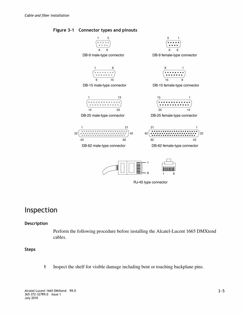
........................................................................................................................................................................Alcatel-Lucent 1665 DMXtend R9.0365-372-327R9.0 Issue 1July 2010
3-5
........................................................................................................................................................................
Cable and fiber installation
Figure 3-1 Connector types and pinouts
Inspection
Description
Perform the following procedure before installing the Alcatel-Lucent 1665 DMXtend cables.
Steps
................................................................................................................................................
1 Inspect the shelf for visible damage including bent or touching backplane pins.
DB-9 male-type connector
DB-15 male-type connector
DB-25 male-type connector
DB-62 male-type connector
1 5
6 9
1 8
9 15
1 13
14 25
1 21
43 62
22 42
DB-9 female-type connector
DB-15 female-type connector
DB-25 female-type connector
DB-62 female-type connector
15
69
8 1
15 9
13 1
25 14
21 1
62 43
42 22
RJ-45 type connector
1
8 1 8
........................................................................................................................................................................3-6 Alcatel-Lucent 1665 DMXtend R9.0
365-372-327R9.0 Issue 1July 2010
........................................................................................................................................................................
Cable and fiber installation
Note: If any backplane pins are damaged, see Appendix D, “Backplane pin replacement” for instructions on repairing the damaged pin(s).
................................................................................................................................................
2 Check off the appropriate box in the Table I-2, Installation checklist.
........................................................................................................................................................E N D O F S T E P S
DS1/E1 cable installation
Description
This section describes how to connect the DS1/E1 transmission cables for function group D or G, to the shelf, route the cables out of the bay and connect the cables to the DSX. Perform this procedure if DS1/E1 cables are required.
Note: When cabling the Alcatel-Lucent 1665 DMXtend to a DSX, the DSX becomes an extension of the Alcatel-Lucent 1665 DMXtend backplane connections. Thus the IN on the Alcatel-Lucent 1665 DMXtend backplane connects to the IN of the DSX and the OUT of the Alcatel-Lucent 1665 DMXtend backplane connects to the OUT of the DSX respectively.
The cables have connectors at the Alcatel-Lucent 1665 DMXtend shelf end and must be wire-wrapped at the DSX end. A total of two function groups fully cabled will have 112 DS1/E1 drop capacity.
Note: The 112 DS1 drops do not include the 16 port DS1 drop available when using the LNW39/LNW391 DS1/DS3/16/3 combo card in slot A/B. Instructions for cabling slot A/B are provided in “DS1 and DS3 hybrid cable installation” (p. 3-32).
Note: The connectorized cable end is grounded to the Alcatel-Lucent 1665 DMXtend frame ground through the backplane. Alcatel-Lucent recommends that the shield at both ends of the DS1/E1 cable be grounded. Ground at the DSX end per office requirements.
Steps
................................................................................................................................................
1 See the engineering job specification. Obtain the DS1/E1 cables per Table 3-2, “DS1/E1 cable assemblies” (p. 3-9) and note the function group where each cable will be used. Label the cables, indicating bay, shelf, function group (D or G) and direction (IN or OUT of the bay) at each end.

........................................................................................................................................................................Alcatel-Lucent 1665 DMXtend R9.0365-372-327R9.0 Issue 1July 2010
3-7
........................................................................................................................................................................
Cable and fiber installation
................................................................................................................................................
2 Connect the function group cables at the Alcatel-Lucent 1665 DMXtend end, carefully matching the correct connector with the appropriate backplane connectors as shown in Figure 3-2, “DS1/E1 cable connectors” (p. 3-7).
Note: DS1/E1 cable retaining screws must be tightened to a maximum of 6.5 in-lb. Do not overtighten.
Note: The first 28 DS1/E1s of a Function Group must be connected to the right side connectors (J1D, J3D, J7G, and J9G). An additional capacity of 28 DS1/E1s, 29-56, are used when the LNW8 circuit pack is used. The second 28 DS1/E1s of a Function Group are connected to the backplane (J2D, J4D, J8G, and J10G).
Note: The DS1/E1 cables that connect to the right side connectors (J1D, J3D, J7G, and J9G) are different from the cables that connect to the connectors in the center of the backplane (J2D, J4D, J8G, and J10G). See Table 3-2, “DS1/E1 cable assemblies” (p. 3-9) for more information.
Figure 3-2 DS1/E1 cable connectors
................................................................................................................................................
3 Route the cables along the backplane and out of the bay to the DSX.
Note: Cables from J1D, J3D, J7G, and J9G route to the right of the shelf (when facing the rear of the shelf) and up the bay frame. See Figure 3-3, “DS1/E1 cable routing to the right” (p. 3-8). Cables from J2D, J4D, J8G, and J10G route to the left of the shelf (when facing the rear of the shelf) and up the bay frame. See Figure 3-4, “DS1/E1 cable routing to the left” (p. 3-8).
Note: When dressing the cables from the connectors in the center of the shelf be sure to allow for access to connectors to the left or right of the center connectors depending

........................................................................................................................................................................3-8 Alcatel-Lucent 1665 DMXtend R9.0
365-372-327R9.0 Issue 1July 2010
........................................................................................................................................................................
Cable and fiber installation
on whether cable dresses to the right or the left. See Figure 3-4, “DS1/E1 cable routing to the left” (p. 3-8).
Figure 3-3 DS1/E1 cable routing to the right
Figure 3-4 DS1/E1 cable routing to the left
................................................................................................................................................
4 Route the cables along the cable rack and into the terminating bay.
................................................................................................................................................
5 Remove slack and cut the DS1/E1 cables to the desired length at the DSX.
................................................................................................................................................
6 Referring to Table 3-3, “DS1 transmission connections” (p. 3-11), carefully observe color codes and wire-wrap the cables at the DSX.

........................................................................................................................................................................Alcatel-Lucent 1665 DMXtend R9.0365-372-327R9.0 Issue 1July 2010
3-9
........................................................................................................................................................................
Cable and fiber installation
................................................................................................................................................
7 Check off the appropriate box in the Table I-2, Installation checklist.
........................................................................................................................................................E N D O F S T E P S
Table 3-2 DS1/E1 cable assemblies
Cable length(feet)
Cable assembly # Description
Alcatel-Lucent 1665 DMXtend backplane connections
10 848954988
20 848955001
30 848923074 Function Group GDS1/E1 In (CA1) andDS1/E1 Out (CA2) Cable
Function Group DDS1/E1 In (CA1) andDS1/E1 Out (CA2) Cable
These cables route to the left (as viewed from the rear of the shelf) and should be used with connectors J2D (IN), J4D (OUT) and J8G (IN), J10G (OUT)
50 848548327
75 848923082
100 848548335
125 848923090
150 848548343
175 848923108
200 848923116
250 848548350
350 848790762
450 848548368
550 848790770
655 848790788
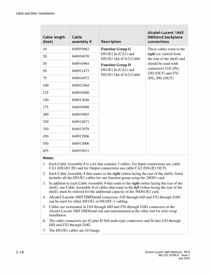
........................................................................................................................................................................3-10 Alcatel-Lucent 1665 DMXtend R9.0
365-372-327R9.0 Issue 1July 2010
........................................................................................................................................................................
Cable and fiber installation
10 848954962 Function Group GDS1/E1 In (CA1) andDS1/E1 Out (CA2) Cable
Function Group DDS1/E1 In (CA1) andDS1/E1 Out (CA2) Cable
These cables route to the right (as viewed from the rear of the shelf) and should be used with connectors J1D (IN), J3D (OUT) and J7G (IN), J9G (OUT)
20 848954970
30 848934964
50 848912473
75 848934972
100 848912564
125 848934980
150 848912648
175 848934998
200 848935003
250 848912671
350 848912978
450 848912986
550 848913000
655 848935011
Notes: 1. Each Cable Assembly # is a kit that contains 2 cables. For Input connections use cable
CA1 (DS1/E1 IN) and for Output connections use cable CA2 (DS1/E1 OUT).
2. Each Cable Assembly # that routes to the right (when facing the rear of the shelf), listed includes all the DS1/E1 cables for one function group using the 28DS1 card.
3. In addition to each Cable Assembly # that route to the right (when facing the rear of the shelf), one Cable Assembly # of cables that route to the left (when facing the rear of the shelf), must be ordered for the additional capacity of the 56DS1/E1 card.
4. Alcatel-Lucent 1665 DMXtend connectors J1D through J4D and J7G through J10G can be used for either DS1/E1 or DS3/EC-1 cabling.
5. Cables are terminated in J1D through J4D and J7G through J10G connectors at the Alcatel-Lucent 1665 DMXtend end and unterminated at the other end for wire-wrap installation.
6. The cable connectors are 62 pins D-Sub male-type connectors and fit into J1D through J4D and J7G through J10G.
7. The DS1/E1 cables are 24 Gauge.
Cable length(feet)
Cable assembly # Description
Alcatel-Lucent 1665 DMXtend backplane connections

........................................................................................................................................................................Alcatel-Lucent 1665 DMXtend R9.0365-372-327R9.0 Issue 1July 2010
3-11
........................................................................................................................................................................
Cable and fiber installation
Table 3-3 DS1 transmission connections
DSX-1 connectionsAlcatel-Lucent 1665 DMXtend backplane connections
Group
ChanDS1
T/R term
T/R color
62-Pin conn.pin# T/R
Function group D conn.
Function group G conn.
In Out In Out
1 1 (1)
2 (2)
3 (3)
4 (4)
B8/B7
B6/B5
B4/B3
B2/B1
W/BL¹
W/O¹
W/G¹
W/BR
19/40
18/39
60/59
17/38
J1D
D
In
J3D
D
Out
J7G
G
In
J9G
G
Out
2 1 (5)
2 (6)
3 (7)
4 (8)
B8/B7
B6/B5
B4/B3
B2/B1
W/S
R/BL
R/O
R/G
58/57
16/37
15/36
14/35
3 1 (9)
2 (10)
3 (11)
4 (12)
B8/B7
B6/B5
B4/B3
B2/B1
R/BR
R/S
BK/BL
BK/O
56/55
13/34
54/53
12/33
4 1 (13)
2 (14)
3 (15)
4 (16)
B8/B7
B6/B5
B4/B3
B2/B1
BK/G
BK/BR
BK/S
Y/BL
11/32
10/31
52/51
9/30
5 1 (17)
2 (18)
3 (19)
4 (20)
B8/B7
B6/B5
B4/B3
B2/B1
Y/O
Y/G
Y/BR
Y/S
50/49
8/29
7/28
6/27
6 1 (21)
2 (22)
3 (23)
4 (24)
B8/B7
B6/B5
B4/B3
B2/B1
V/BL
V/O
V/G
V/BR
48/47
5/26
46/45
4/25
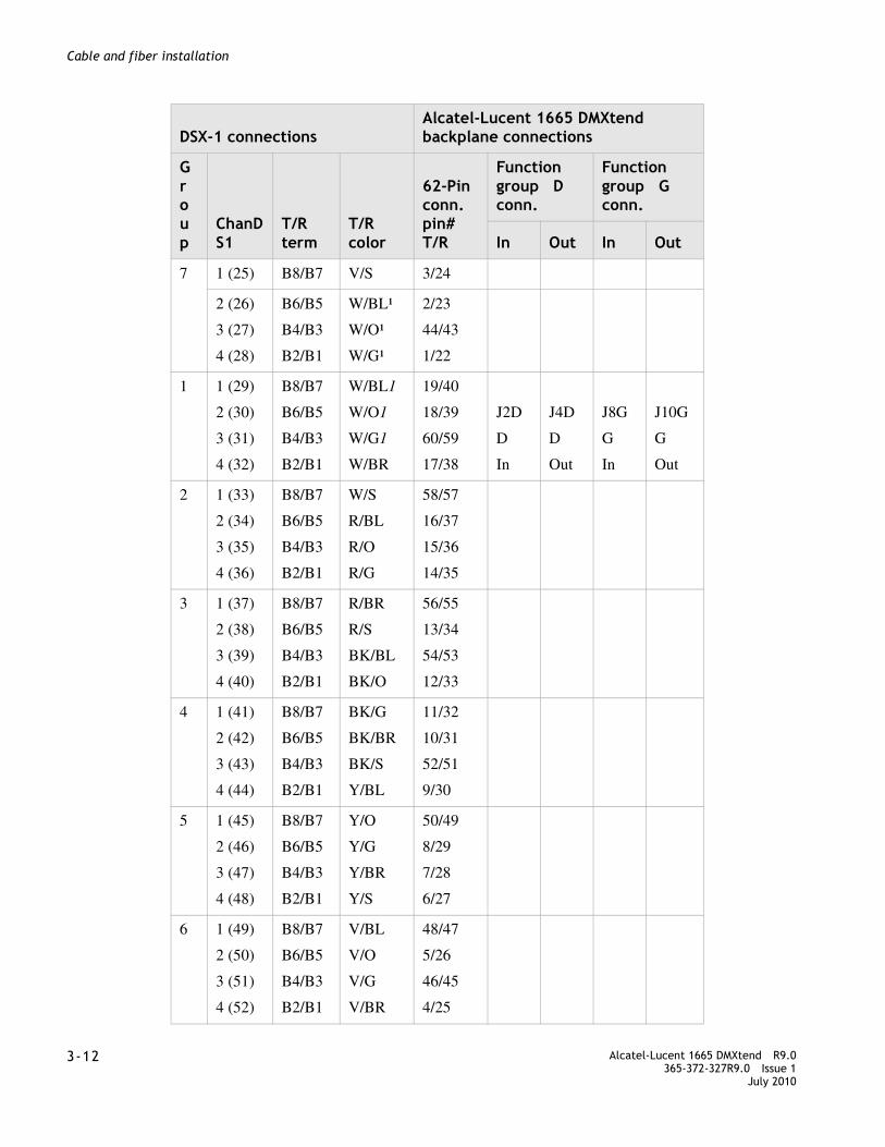
........................................................................................................................................................................3-12 Alcatel-Lucent 1665 DMXtend R9.0
365-372-327R9.0 Issue 1July 2010
........................................................................................................................................................................
Cable and fiber installation
7 1 (25) B8/B7 V/S 3/24
2 (26)
3 (27)
4 (28)
B6/B5
B4/B3
B2/B1
W/BL¹
W/O¹
W/G¹
2/23
44/43
1/22
1 1 (29)
2 (30)
3 (31)
4 (32)
B8/B7
B6/B5
B4/B3
B2/B1
W/BL1
W/O1
W/G1
W/BR
19/40
18/39
60/59
17/38
J2D
D
In
J4D
D
Out
J8G
G
In
J10G
G
Out
2 1 (33)
2 (34)
3 (35)
4 (36)
B8/B7
B6/B5
B4/B3
B2/B1
W/S
R/BL
R/O
R/G
58/57
16/37
15/36
14/35
3 1 (37)
2 (38)
3 (39)
4 (40)
B8/B7
B6/B5
B4/B3
B2/B1
R/BR
R/S
BK/BL
BK/O
56/55
13/34
54/53
12/33
4 1 (41)
2 (42)
3 (43)
4 (44)
B8/B7
B6/B5
B4/B3
B2/B1
BK/G
BK/BR
BK/S
Y/BL
11/32
10/31
52/51
9/30
5 1 (45)
2 (46)
3 (47)
4 (48)
B8/B7
B6/B5
B4/B3
B2/B1
Y/O
Y/G
Y/BR
Y/S
50/49
8/29
7/28
6/27
6 1 (49)
2 (50)
3 (51)
4 (52)
B8/B7
B6/B5
B4/B3
B2/B1
V/BL
V/O
V/G
V/BR
48/47
5/26
46/45
4/25
DSX-1 connectionsAlcatel-Lucent 1665 DMXtend backplane connections
Group
ChanDS1
T/R term
T/R color
62-Pin conn.pin# T/R
Function group D conn.
Function group G conn.
In Out In Out

........................................................................................................................................................................Alcatel-Lucent 1665 DMXtend R9.0365-372-327R9.0 Issue 1July 2010
3-13
........................................................................................................................................................................
Cable and fiber installation
DS3/EC-1 cable installation
Description
This section describes how to connect the DS3/EC-1 cables to the Alcatel-Lucent 1665 DMXtend shelf and route the cables out of the bay and to the DS3/EC-1 terminating equipment.This procedure covers both the 12 cable and the 24 cable DS3/EC1 cables. Perform this procedure if DS3/EC-1 cables are required.
Note: When cabling the Alcatel-Lucent 1665 DMXtend to a DSX, the DSX becomes an extension of the Alcatel-Lucent 1665 DMXtend backplane connections. Therefore, the IN on the Alcatel-Lucent 1665 DMXtend backplane connects to the IN of the DSX and the OUT of the Alcatel-Lucent 1665 DMXtend backplane connects to the OUT of the DSX respectively
DS3/EC-1 cable options are listed in Table 3-4, “DS3/EC-1 cable assemblies” (p. 3-17).
DS3/EC-1 transmission connections are in Table 3-5, “Twenty-four cable DS3/EC-1 transmission connections” (p. 3-26) and Table 3-6, “Twelve cable DS3/EC-1 transmission connections” (p. 3-30). Total of two function groups fully cabled will have 96 DS3 drop capacity.
Note: The 96 DS3 figure does not include the 3 DS3 drops available when using the LNW39/LNW391 16/DS1/3/DS3 combo card in slot A/B. Instructions for cabling slot A/B are provided in “DS1 and DS3 hybrid cable installation” (p. 3-32).
7 1 (53) B8/B7 V/S 3/24
2 (54)
3 (55)
4 (56)
B6/B5
B4/B3
B2/B1
W/BL¹
W/O¹
W/G¹
2/23
44/43
1/22
Notes: 1. Some wire colors are used twice. White binder cables are for Channel 1
through 25 or Channel 29 through 53 and blue binder cables are for Channels 26, 27 and 28 or Channels 54, 55 and 56 are shaded.
DSX-1 connectionsAlcatel-Lucent 1665 DMXtend backplane connections
Group
ChanDS1
T/R term
T/R color
62-Pin conn.pin# T/R
Function group D conn.
Function group G conn.
In Out In Out

........................................................................................................................................................................3-14 Alcatel-Lucent 1665 DMXtend R9.0
365-372-327R9.0 Issue 1July 2010
........................................................................................................................................................................
Cable and fiber installation
Steps
................................................................................................................................................
1 See the engineering job specification. Obtain the DS3/EC-1 cables per Table 3-4, “DS3/EC-1 cable assemblies” (p. 3-17) and note the function group where each cable will be used. Label the cables, indicating bay, shelf, function group (D or G) and direction (IN or OUT of the bay) at each end.
Note: The first 12/24 ports of a function unit must be cabled to the right side connectors (J1D, J3D, J7G, and J9G), the additional DS3/EC-1 capacity ports (25 - 48) are cabled to the center connectors of the shelf (J2D, J4D, J8G, and J10G).
................................................................................................................................................
2 Connect the function group cables at the Alcatel-Lucent 1665 DMXtend end, carefully matching the correct connector with the appropriate backplane connectors as shown in Figure 3-5, “DS3/EC-1 cable connections” (p. 3-15).
Note: DS3/EC-1 and TMUX cable retaining screws must be tightened to a maximum of 6.5 in-lb. Do not overtighten.
Note: The 12 conductor DS3/EC-1 cables that support the LNW16 12DS3/EC-1 pack connect only to the right side connectors (J1D, J3D, J7G, and J9G). The connectors in the center of the backplane (J2D, J4D, J8G, and J10G) are not used with the LNW16. See Table 3-4, “DS3/EC-1 cable assemblies” (p. 3-17) for more information.
Note: The first 12/24 DS3/EC-1s of a Function Group must be connected to the right side connectors (J1D, J3D, J7G, and J9G). See Figure 3-6, “DS3/EC-1 cable routing to the right” (p. 3-15). The additional capacity of 24 DS3/EC-1s of the Function Group use the connectors located to the center of the backplane (J2D, J4D, J8G, and J10G).
Note: The 24 conductor DS3/EC-1 cables that connect to the right side connectors (J1D, J3D, J7G, and J9G) are different from the 24 cable DS3/EC-1 cables that connect to the connectors in the center of the backplane (J2D, J4D, J8G, and J10G). See Table 3-4, “DS3/EC-1 cable assemblies” (p. 3-17) for more information.
Function group Associated connector (DS3/EC-1)
G G IN (J7G and J8G) G OUT (J9G and J10G)
D D IN (J1D and J2D) D OUT (J3D and J4D)

........................................................................................................................................................................Alcatel-Lucent 1665 DMXtend R9.0365-372-327R9.0 Issue 1July 2010
3-15
........................................................................................................................................................................
Cable and fiber installation
Figure 3-5 DS3/EC-1 cable connections
................................................................................................................................................
3 Route the cables along the backplane and out of the bay to the DSX per Figure 3-6, “DS3/EC-1 cable routing to the right” (p. 3-15).
Figure 3-6 DS3/EC-1 cable routing to the right
Notes: The 12-conductor DS3/EC-1 cable is showing that this cable could be either the 12- or 24-conductor DS3/EC-1 cable.
Ports

........................................................................................................................................................................3-16 Alcatel-Lucent 1665 DMXtend R9.0
365-372-327R9.0 Issue 1July 2010
........................................................................................................................................................................
Cable and fiber installation
Figure 3-7 DS3/EC-1 cable routing to the left
Notes: The 12-conductor DS3/EC-1 cable is shown.
................................................................................................................................................
4 Route the cables along the cable rack and into the terminating bay (DSX or other terminating transmission equipment).
................................................................................................................................................
5 Cut the cables to desired length and install the BNC connectors shipped with the cable assemblies.
Note: When installing BNC connectors, follow the manufacturer’s instruction carefully to ensure a proper connection. Failure to do so may result in faulty DS3/EC-1 signals as a result of improperly installed BNC connectors.
................................................................................................................................................
6 Connect the cables to their respective positions on the terminating equipment.See Table 3-5, “Twenty-four cable DS3/EC-1 transmission connections” (p. 3-26) or Table 3-6, “Twelve cable DS3/EC-1 transmission connections” (p. 3-30) for DS3/EC-1 connections.
Note: The 12-port cable and the 24-port cable use different signal grounds based on the circuit pack not the backplane. There is no issue interchanging these cables on the backplane. The DS3/EC-1 Signals are common between both cables.
................................................................................................................................................
7 Check off the appropriate box in the Table I-2, Installation checklist.

........................................................................................................................................................................Alcatel-Lucent 1665 DMXtend R9.0365-372-327R9.0 Issue 1July 2010
3-17
........................................................................................................................................................................
Cable and fiber installation
Table 3-4 DS3/EC-1 cable assemblies
DescriptionCable assembly #
Cable length(feet)
Alcatel-Lucent 1665 DMXtend backplane connections
Function group D and G12 Cable DS3/EC-1 In (CA1) and 12 Cable DS3/EC-1 Out (CA2) Cable
848955084 10
848955092 20
848955100 30
848955118 40
848912234 50 These cables route to the right (as viewed from the rear of the shelf) and should be used with connectors J1D (IN), J3D (OUT) and J7G (IN), J9G (OUT)
848994109 60
848912242 100
848912259 150
848912267 250
848912192 450 Ne to Ne Only
848912333 450 735/734 Splice
848912200 700 735/734 Splice
848912218 900 735/734 Splice
Function group D and GDS3/EC-1#1-12 Cables w/ no BNC, for LNW16, LNW18 similar to above except no BNCs are shipped loose.
See below for different vendors’ BNC plugs.
849040787 10
849040795 20
849040803 30
849040811 40
849040829 50
849040837 60
849040845 100
849040852 150
849040860 250
849040878 450 Ne to Ne Only
849041751 450 735/734 Splice
849041769 750 735/734 Splice
849041777 900 735/734 Splice

........................................................................................................................................................................3-18 Alcatel-Lucent 1665 DMXtend R9.0
365-372-327R9.0 Issue 1July 2010
........................................................................................................................................................................
Cable and fiber installation
The following kits include 12 individually bagged BNCs with instructions plus one spare:
KINGS 75ohm 735A cable type (12)BNC Plug Kit
848965778
KINGS 75ohm 734D cable type (12)BNC Plug Kit
848965786
TROMPETER 75ohm 735A cable type (12)BNC Plug Kit
848965794
TROMPETER 75ohm 734D cable type (12)BNC Plug Kit
848965802
DescriptionCable assembly #
Cable length(feet)
Alcatel-Lucent 1665 DMXtend backplane connections
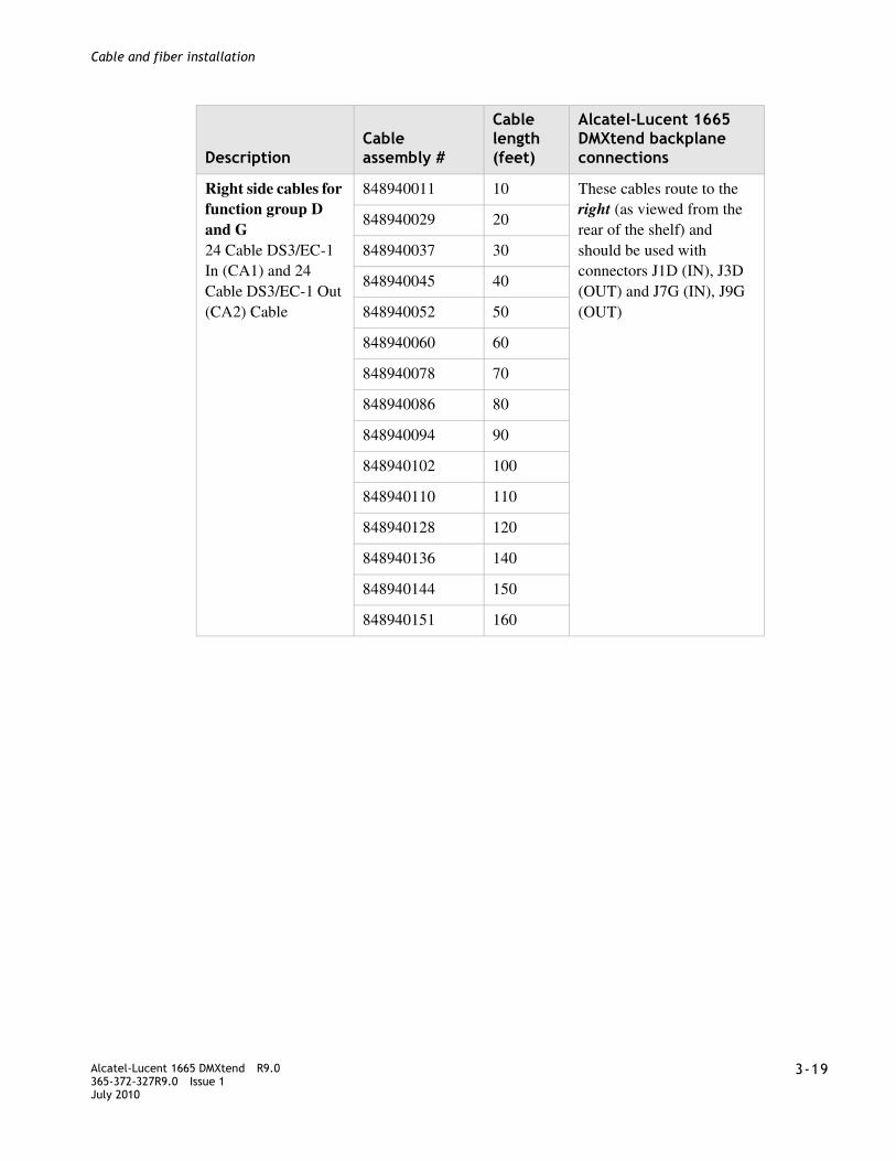
........................................................................................................................................................................Alcatel-Lucent 1665 DMXtend R9.0365-372-327R9.0 Issue 1July 2010
3-19
........................................................................................................................................................................
Cable and fiber installation
Right side cables for function group D and G24 Cable DS3/EC-1 In (CA1) and 24 Cable DS3/EC-1 Out (CA2) Cable
848940011 10 These cables route to the right (as viewed from the rear of the shelf) and should be used with connectors J1D (IN), J3D (OUT) and J7G (IN), J9G (OUT)
848940029 20
848940037 30
848940045 40
848940052 50
848940060 60
848940078 70
848940086 80
848940094 90
848940102 100
848940110 110
848940128 120
848940136 140
848940144 150
848940151 160
DescriptionCable assembly #
Cable length(feet)
Alcatel-Lucent 1665 DMXtend backplane connections

........................................................................................................................................................................3-20 Alcatel-Lucent 1665 DMXtend R9.0
365-372-327R9.0 Issue 1July 2010
........................................................................................................................................................................
Cable and fiber installation
Right side cables for function group D and G24 Cable DS3/EC-1 In (CA1) and 24 Cable DS3/EC-1 Out (CA2) Cable
848940169 180
848940177 200
848940185 250
848940193 300 Ne to Ne Only
848940201 400 Ne to Ne Only
848940219 450 Ne to Ne Only
848939856 250 735A/734 Splice
848939864 300 735A/734 Splice
848939872 300 735A/734 Splice
848939880 325 735A/734 Splice
848939898 350 735A/734 Splice
848939906 375 735A/734 Splice
848939914 400 735A/734 Splice
848939922 425 735A/734 Splice
848939930 450 735A/734 Splice
848939948 750 735A/734 Splice NE to NE
848939955 900 735A/734 Splice NE to NE
Right side cables for function group D and Gsimilar to above except no BNC’s are shipped loose.
See below for different vendors’ BNC Plug Kits.
849041108 10 These cables route to the right (as viewed from the rear of the shelf) and should be used with connectors J1D (IN), J3D (OUT) and J7G (IN), J9G (OUT)
849041116 20
849041124 30
849041132 40
849041140 50
849041157 60
849041165 70
849041173 80
849041181 90
849041199 100
DescriptionCable assembly #
Cable length(feet)
Alcatel-Lucent 1665 DMXtend backplane connections

........................................................................................................................................................................Alcatel-Lucent 1665 DMXtend R9.0365-372-327R9.0 Issue 1July 2010
3-21
........................................................................................................................................................................
Cable and fiber installation
Right side cables for function group D and Gsimilar to above except no BNC’s are shipped loose.
See below for different vendors’ BNC Plug Kits.
849041207 110 These cables route to the right (as viewed from the rear of the shelf) and should be used with connectors J1D (IN), J3D (OUT) and J7G (IN), J9G (OUT)
849041215 120
849041223 140
849041231 150
849041249 160
849041256 180
849041264 200
849041272 250
849041280 300 Ne to Ne Only
849041298 400 Ne to Ne Only
849041306 450 Ne to Ne Only
849041892 250 735A/734 Splice
849041900 275 735A/734 Splice
849041926 300 735A/734 Splice
849041934 325 735A/734 Splice
849041942 350 735A/734 Splice
849041959 375 735A/734 Splice
849041967 400 735A/734 Splice
849041975 425 735A/734 Splice
849041983 450 735A/734 Splice
849041991 750 735A/734 Splice NE to NE
849042007 900 735A/734 Splice NE to NE
These kits include 25/50 individually bagged BNCs w/ assembly instructions
KINGS 75ohm 735A cable type (24)BNC Plug Kit
848963062
KINGS 75ohm 734D cable type (24)BNC Plug Kit
848963070
DescriptionCable assembly #
Cable length(feet)
Alcatel-Lucent 1665 DMXtend backplane connections
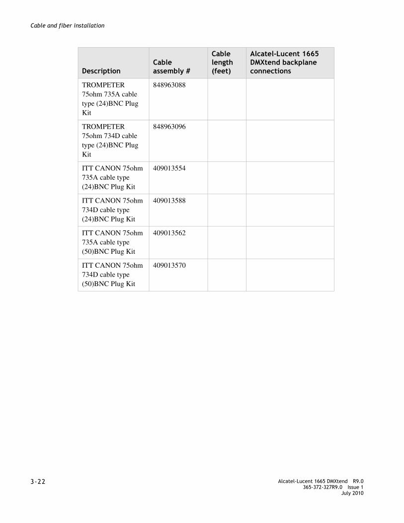
........................................................................................................................................................................3-22 Alcatel-Lucent 1665 DMXtend R9.0
365-372-327R9.0 Issue 1July 2010
........................................................................................................................................................................
Cable and fiber installation
TROMPETER 75ohm 735A cable type (24)BNC Plug Kit
848963088
TROMPETER 75ohm 734D cable type (24)BNC Plug Kit
848963096
ITT CANON 75ohm 735A cable type (24)BNC Plug Kit
409013554
ITT CANON 75ohm 734D cable type (24)BNC Plug Kit
409013588
ITT CANON 75ohm 735A cable type (50)BNC Plug Kit
409013562
ITT CANON 75ohm 734D cable type (50)BNC Plug Kit
409013570
DescriptionCable assembly #
Cable length(feet)
Alcatel-Lucent 1665 DMXtend backplane connections

........................................................................................................................................................................Alcatel-Lucent 1665 DMXtend R9.0365-372-327R9.0 Issue 1July 2010
3-23
........................................................................................................................................................................
Cable and fiber installation
Left side cables for function group D and G24 Cable DS3/EC-1 In (CA1) and 24 Cable DS3/EC-1 Out (CA2) Cable
848923124 10 These cables route to the left (as viewed from the rear of the shelf) and should be used with connectors J2D (IN), J4D (OUT) and J8G (IN), J10G (OUT)
848923132 20
848923140 30
848923157 40
848839478 50
848923165 60
848923173 70
848923181 80
848923199 90
848839486 100
848923207 110
848923215 120
848923223 140
848839494 150
848923231 160
848923249 180
848923256 200
848839502 250
848923264 300 Ne to Ne Only
848923272 400 Ne to Ne Only
848839510 450 Ne to Ne Only
848932083 250 735A/734 Splice
848932018 275 735A/734 Splice
848932026 300 735A/734 Splice
848932034 325 735A/734 Splice
848932042 350 735A/734 Splice
848932059 375 735A/734 Splice
848932067 400 735A/734 Splice
DescriptionCable assembly #
Cable length(feet)
Alcatel-Lucent 1665 DMXtend backplane connections

........................................................................................................................................................................3-24 Alcatel-Lucent 1665 DMXtend R9.0
365-372-327R9.0 Issue 1July 2010
........................................................................................................................................................................
Cable and fiber installation
Left side cables for function group D and G24 Cable DS3/EC-1 In (CA1) and 24 Cable DS3/EC-1 Out (CA2) Cable
848932075 425 735A/734 Splice
848839528 450 735A/734 Splice
848839536 750 735A/734 Splice Ne to Ne
848839544 900 735A/734 Splice Ne to Ne
Left side cables for function group D and GSimilar to above except no BNC’s are shipped loose.
See above for different vendors’ BNC Plug Kits
849040886 10 These cables route to the left (as viewed from the rear of the shelf) and should be used with connectors J2D (IN), J4D (OUT) and J8G (IN), J10G (OUT)
849040894 20
849040902 30
849040910 40
849040928 50
849040936 60
849040944 70
849040951 80
849040969 90
849040977 100
849040985 110
849040993 120
849041009 140
849041017 150
849041025 160
849041033 180
849041041 200
849041066 250
849041074 300 Ne to Ne Only
849041082 400 Ne to Ne Only
849041090 450 Ne to Ne Only
848932083 250 735A/734 Splice
DescriptionCable assembly #
Cable length(feet)
Alcatel-Lucent 1665 DMXtend backplane connections

........................................................................................................................................................................Alcatel-Lucent 1665 DMXtend R9.0365-372-327R9.0 Issue 1July 2010
3-25
........................................................................................................................................................................
Cable and fiber installation
Left side cables for function group D and GSimilar to above except no BNC’s are shipped loose.
See above for different vendors’ BNC Plug Kits
848932018 275 735A/734 Splice
848932026 300 735A/734 Splice
848932034 325 735A/734 Splice
848932042 350 735A/734 Splice
848932059 375 735A/734 Splice
848932067 400 735A/734 Splice
848932075 425 735A/734 Splice
848839528 450 735A/734 Splice
848839536 750 735A/734 Splice Ne to Ne
848839544 900 735A/734 Splice Ne to Ne
Notes: 1. All the DS3/EC-1 cable assemblies can be used for either function group D or G.
2. Alcatel-Lucent 1665 DMXtend connectors J1D through J4D and J7G through J10G can be used for either DS1/E1 or DS3/EC-1 cabling.
3. Each Cable assembly # listed above contains two cable assemblies therefore a quantity of two per function group in the case of the 24 pair cables, must be ordered for the additional capacity.
4. For Input connections use cable CA1 (DS3/EC-1 IN) and for Output connections use cable CA2 (DS3/EC-1 OUT).
5. 735A cable is used to connect Alcatel-Lucent 1665 DMXtend to DSX-3 or another NE (10 to 450 ft. length).
6. The cable connectors are 62 pins D-Sub male-type connectors and fit into J1D through J4D and J7G through J10G.
DescriptionCable assembly #
Cable length(feet)
Alcatel-Lucent 1665 DMXtend backplane connections
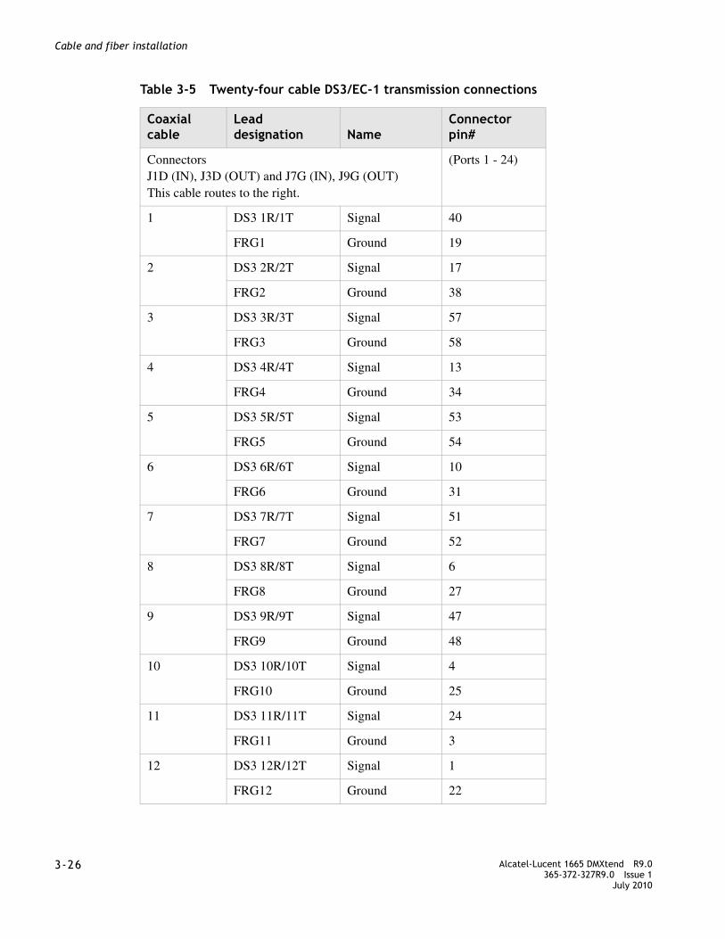
........................................................................................................................................................................3-26 Alcatel-Lucent 1665 DMXtend R9.0
365-372-327R9.0 Issue 1July 2010
........................................................................................................................................................................
Cable and fiber installation
Table 3-5 Twenty-four cable DS3/EC-1 transmission connections
Coaxial cable
Lead designation Name
Connector pin#
Connectors J1D (IN), J3D (OUT) and J7G (IN), J9G (OUT)This cable routes to the right.
(Ports 1 - 24)
1 DS3 1R/1T Signal 40
FRG1 Ground 19
2 DS3 2R/2T Signal 17
FRG2 Ground 38
3 DS3 3R/3T Signal 57
FRG3 Ground 58
4 DS3 4R/4T Signal 13
FRG4 Ground 34
5 DS3 5R/5T Signal 53
FRG5 Ground 54
6 DS3 6R/6T Signal 10
FRG6 Ground 31
7 DS3 7R/7T Signal 51
FRG7 Ground 52
8 DS3 8R/8T Signal 6
FRG8 Ground 27
9 DS3 9R/9T Signal 47
FRG9 Ground 48
10 DS3 10R/10T Signal 4
FRG10 Ground 25
11 DS3 11R/11T Signal 24
FRG11 Ground 3
12 DS3 12R/12T Signal 1
FRG12 Ground 22

........................................................................................................................................................................Alcatel-Lucent 1665 DMXtend R9.0365-372-327R9.0 Issue 1July 2010
3-27
........................................................................................................................................................................
Cable and fiber installation
13 DS3 13R/12T Signal 59
FRG13 Ground 60
14 DS3 14R/12T Signal 16
FRG14 Ground 37
15 DS3 15R/12T Signal 36
FRG15 Ground 15
16 DS3 16R/12T Signal 55
FRG16 Ground 56
17 DS3 17R/12T Signal 12
FRG17 Ground 33
18 DS3 18R/12T Signal 32
FRG18 Ground 11
19 DS3 19R/12T Signal 9
FRG19 Ground 30
20 DS3 20R/12T Signal 49
FRG20 Ground 50
21 DS3 21R/12T Signal 28
FRG21 Ground 7
22 DS3 22R/12T Signal 5
FRG22 Ground 26
23 DS3 23R/12T Signal 45
FRG23 Ground 46
24 DS3 24R/12T Signal 43
FRG24 Ground 44
Connectors J2D (IN), J4D (OUT) and J8G (IN), J10G (OUT)This Cable Routes to the Left.
(Ports 25 - 48)
25 DS3 25R/12T Signal 40
FRG25 Ground 19
Coaxial cable
Lead designation Name
Connector pin#

........................................................................................................................................................................3-28 Alcatel-Lucent 1665 DMXtend R9.0
365-372-327R9.0 Issue 1July 2010
........................................................................................................................................................................
Cable and fiber installation
26 DS3 26R/12T Signal 17
FRG26 Ground 38
27 DS3 27R/12T Signal 57
FRG27 Ground 58
28 DS3 28R/12T Signal 13
FRG28 Ground 34
29 DS3 29R/12T Signal 53
FRG29 Ground 54
30 DS3 30R/12T Signal 10
FRG30 Ground 31
31 DS3 31R/12T Signal 51
FRG31 Ground 52
32 DS3 32R/12T Signal 6
FRG32 Ground 27
33 DS3 33R/12T Signal 47
FRG33 Ground 48
34 DS3 34R/12T Signal 4
FRG34 Ground 25
35 DS3 35R/12T Signal 24
FRG35 Ground 3
36 DS3 36R/12T Signal 1
FRG36 Ground 22
37 DS3 37R/12T Signal 59
FRG37 Ground 60
38 DS3 38R/12T Signal 16
FRG38 Ground 37
39 DS3 39R/12T Signal 36
FRG39 Ground 15
Coaxial cable
Lead designation Name
Connector pin#

........................................................................................................................................................................Alcatel-Lucent 1665 DMXtend R9.0365-372-327R9.0 Issue 1July 2010
3-29
........................................................................................................................................................................
Cable and fiber installation
40 DS3 40R/12T Signal 55
FRG40 Ground 56
41 DS3 41R/12T Signal 12
FRG41 Ground 33
42 DS3 42R/12T Signal 32
FRG42 Ground 11
43 DS3 43R/12T Signal 9
FRG43 Ground 30
44 DS3 44R/12T Signal 49
FRG44 Ground 50
45 DS3 45R/12T Signal 28
FRG45 Ground 7
46 DS3 46R/12T Signal 5
FRG46 Ground 26
47 DS3 47R/12T Signal 45
FRG47 Ground 46
48 DS3 48R/12T Signal 43
FRG48 Ground 44
Notes: 1. Lead designation for EC1 connection for cable# x should be read as
EC1 xR/xT instead of DS3 xR/xT, where x is a number from 1 to 48.
Coaxial cable
Lead designation Name
Connector pin#

........................................................................................................................................................................3-30 Alcatel-Lucent 1665 DMXtend R9.0
365-372-327R9.0 Issue 1July 2010
........................................................................................................................................................................
Cable and fiber installation
Table 3-6 Twelve cable DS3/EC-1 transmission connections
Coaxial cable
Lead designation Name
Connector pin#
Connectors J1D (IN), J3D (OUT) and J7G (IN), J9G (OUT)This Cable Routes to the Right.
(Ports 1 - 12)
1 DS3 1R/1T Signal 40
FRG1 Ground 39
2 DS3 2R/2T Signal 17
FRG2 Ground 18
3 DS3 3R/3T Signal 57
FRG3 Ground 58
4 DS3 4R/4T Signal 13
FRG4 Ground 14
5 DS3 5R/5T Signal 53
FRG5 Ground 54
6 DS3 6R/6T Signal 10
FRG6 Ground 11
7 DS3 7R/7T Signal 51
FRG8 Ground 50
8 DS3 8R/8T Signal 6
FRG8 Ground 7
9 DS3 9R/9T Signal 47
FRG9 Ground 46
10 DS3 10R/10T Signal 4
FRG10 Ground 3
11 DS3 11R/11T Signal 24
FRG11 Ground 23
12 DS3 12R/12T Signal 1
FRG12 Ground 2
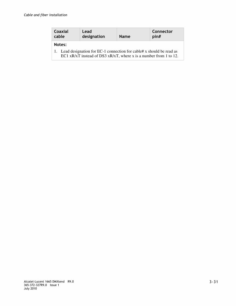
........................................................................................................................................................................Alcatel-Lucent 1665 DMXtend R9.0365-372-327R9.0 Issue 1July 2010
3-31
........................................................................................................................................................................
Cable and fiber installation
Notes: 1. Lead designation for EC-1 connection for cable# x should be read as
EC1 xR/xT instead of DS3 xR/xT, where x is a number from 1 to 12.
Coaxial cable
Lead designation Name
Connector pin#
........................................................................................................................................................................3-32 Alcatel-Lucent 1665 DMXtend R9.0
365-372-327R9.0 Issue 1July 2010
........................................................................................................................................................................
Cable and fiber installation
DS1 and DS3 hybrid cable installation
Description
This section describes how to connect the DS1 and DS3 Hybrid cables to the Alcatel-Lucent 1665 DMXtend shelf and route the cables out of the bay and to the DS1 and DS3 Hybrid Cable terminating equipment. Perform this procedure if DS1 and DS3 Hybrid cables are required.
Note: When cabling the Alcatel-Lucent 1665 DMXtend to a DSX, the DSX becomes an extension of the Alcatel-Lucent 1665 DMXtend backplane connections. Therefore, the IN on the Alcatel-Lucent 1665 DMXtend backplane connects to the IN of the DSX and the OUT of the Alcatel-Lucent 1665 DMXtend backplane connects to the OUT of the DSX respectively
DS1 and DS3 Hybrid cable options are listed in Table 3-7, “DS1 and DS3 hybrid cable assemblies” (p. 3-35).
DS1 and DS3 Hybrid Cable transmission connections are in Table 3-9, “DS1 and DS3 hybrid cable DS1 transmission connections” (p. 3-39).
Steps
................................................................................................................................................
8 See the engineering job specification. Obtain the DS1 and DS3 Hybrid cables per Table 3-7, “DS1 and DS3 hybrid cable assemblies” (p. 3-35) and note the function group where each cable will be used. Label the cables, indicating bay, shelf, function group (A and B) and direction (IN or OUT of the bay) at each end.
................................................................................................................................................
9 Connect the function group A/B cables at the Alcatel-Lucent 1665 DMXtend end, carefully matching the correct connector with the appropriate backplane connectors as shown in Figure 3-8, “DS1 and DS3 hybrid cable connections” (p. 3-33).
Note: The DS1 and DS3 cable retaining screws must be tightened to a maximum of 6.5 in-lb. Do not overtighten.
Note: The DS1 and DS3 Hybrid Cable only supports slots A1/B1 and A2/B2 and only connects to J5A/B (IN) and J6A/B (OUT).
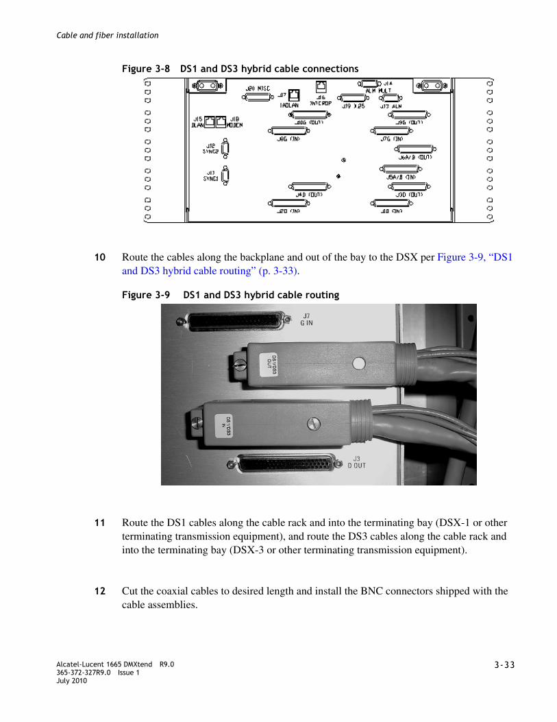
........................................................................................................................................................................Alcatel-Lucent 1665 DMXtend R9.0365-372-327R9.0 Issue 1July 2010
3-33
........................................................................................................................................................................
Cable and fiber installation
Figure 3-8 DS1 and DS3 hybrid cable connections
................................................................................................................................................
10 Route the cables along the backplane and out of the bay to the DSX per Figure 3-9, “DS1 and DS3 hybrid cable routing” (p. 3-33).
Figure 3-9 DS1 and DS3 hybrid cable routing
................................................................................................................................................
11 Route the DS1 cables along the cable rack and into the terminating bay (DSX-1 or other terminating transmission equipment), and route the DS3 cables along the cable rack and into the terminating bay (DSX-3 or other terminating transmission equipment).
................................................................................................................................................
12 Cut the coaxial cables to desired length and install the BNC connectors shipped with the cable assemblies.
........................................................................................................................................................................3-34 Alcatel-Lucent 1665 DMXtend R9.0
365-372-327R9.0 Issue 1July 2010
........................................................................................................................................................................
Cable and fiber installation
Note: When installing BNC connectors, follow the manufacturer’s instruction carefully to ensure a proper connection. Failure to do so may result in faulty DS3 signals as a result of improperly installed BNC connectors.
................................................................................................................................................
13 Referring to Table 3-8, “DS1 and DS3 hybrid cable DS3 transmission connections” (p. 3-39) connect the cables to their respective positions on the terminating equipment or DSX.
................................................................................................................................................
14 Remove slack and cut the DS1 cables to the desired length at the DSX.
................................................................................................................................................
15 Referring to Table 3-9, “DS1 and DS3 hybrid cable DS1 transmission connections” (p. 3-39), carefully observe color codes and wire-wrap the cables at the DSX.
................................................................................................................................................
16 Check off the appropriate box in the Table I-2, Installation checklist.
........................................................................................................................................................E N D O F S T E P S

........................................................................................................................................................................Alcatel-Lucent 1665 DMXtend R9.0365-372-327R9.0 Issue 1July 2010
3-35
........................................................................................................................................................................
Cable and fiber installation
Table 3-7 DS1 and DS3 hybrid cable assemblies
DescriptionCable assembly #
Cable length(feet)
Alcatel-Lucent 1665 DMXtend backplane connections
Function group A/BDS1 and DS3 hybrid cable In (CA1) and DS1 and DS3 hybrid cable Out (CA2)
848955035 10 J5A/B(IN)J6A/B(OUT)
848955043 20
848935029 30
848875043 50
848935037 75
848875050 100
848935045 125
848875076 150
848935052 175
848935060 200
848875084 250
848875100 350
848875126 4506
848935078 5507
848935086 6557

........................................................................................................................................................................3-36 Alcatel-Lucent 1665 DMXtend R9.0
365-372-327R9.0 Issue 1July 2010
........................................................................................................................................................................
Cable and fiber installation
Function group A/BDS1 and DS3 hybrid cable In (CA1) and DS1 and DS3 hybrid cable Out (CA2)
Similar to above except no BNC plugs ship loose.
See below for different vendors’ BNC plugs.
849041561 10 J5A/B(IN)J6A/B(OUT)
849041579 20
849041587 30
849041595 50
849041603 75
849041611 100
849041629 125
849041637 150
849041645 175
849041652 200
849041660 250
849041678 350 J5A/B(IN)J6A/B(OUT)
849041686 450
849041694 550
849041702 655
DescriptionCable assembly #
Cable length(feet)
Alcatel-Lucent 1665 DMXtend backplane connections
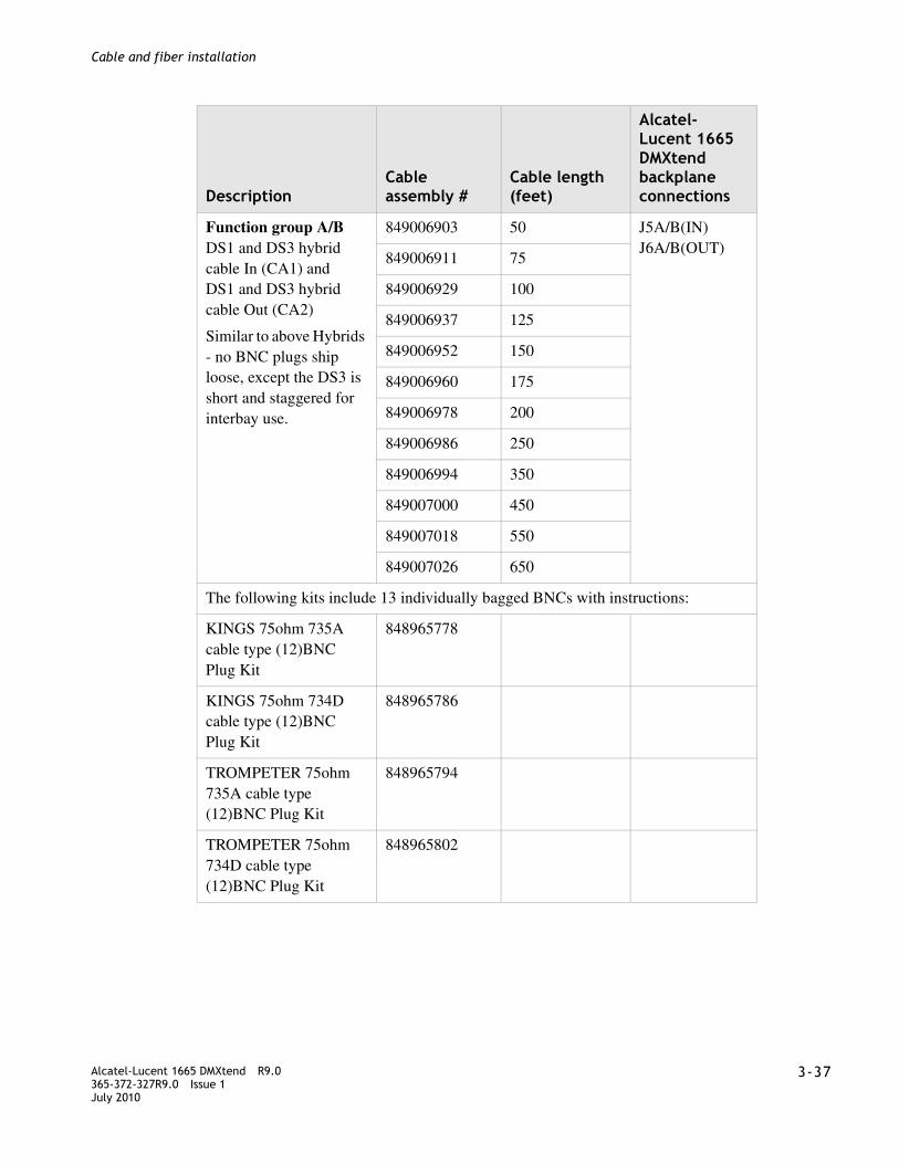
........................................................................................................................................................................Alcatel-Lucent 1665 DMXtend R9.0365-372-327R9.0 Issue 1July 2010
3-37
........................................................................................................................................................................
Cable and fiber installation
Function group A/BDS1 and DS3 hybrid cable In (CA1) and DS1 and DS3 hybrid cable Out (CA2)
Similar to above Hybrids - no BNC plugs ship loose, except the DS3 is short and staggered for interbay use.
849006903 50 J5A/B(IN)J6A/B(OUT)
849006911 75
849006929 100
849006937 125
849006952 150
849006960 175
849006978 200
849006986 250
849006994 350
849007000 450
849007018 550
849007026 650
The following kits include 13 individually bagged BNCs with instructions:
KINGS 75ohm 735A cable type (12)BNC Plug Kit
848965778
KINGS 75ohm 734D cable type (12)BNC Plug Kit
848965786
TROMPETER 75ohm 735A cable type (12)BNC Plug Kit
848965794
TROMPETER 75ohm 734D cable type (12)BNC Plug Kit
848965802
DescriptionCable assembly #
Cable length(feet)
Alcatel-Lucent 1665 DMXtend backplane connections

........................................................................................................................................................................3-38 Alcatel-Lucent 1665 DMXtend R9.0
365-372-327R9.0 Issue 1July 2010
........................................................................................................................................................................
Cable and fiber installation
Notes: 1. All the DS1 and DS3 Hybrid (28 DS1/3DS3) cable assemblies can only be used
for function group A/B.
2. Alcatel-Lucent 1665 DMXtend connectors J5A/B(IN) and J6A/B(OUT) can only be used for the DS1 and DS3 Hybrid (16 DS1/3DS3) cable assemblies.
3. Each Cable assembly# listed above contains two cable assemblies.
4. For Input connections use cable CA1 (DS1 and DS3 Hybrid IN) and for Output connections use cable CA2 (DS1 and DS3 Hybrid OUT).
5. For the Coaxial cable 735A cable is used to connect Alcatel-Lucent 1665 DMXtend to DSX-3 or another NE (50 to 350 ft. length).
6. For the Coaxial cable the 450 ft. cable (848548319) is not suitable for connection to a DSX-3.
7. For the Coaxial cable the longest distance allowed to connect Alcatel-Lucent 1665 DMXtend to another NE is 450ft. of length. The 550 and 655 ft. cables are for the DS1 cables only and the Coaxial cable must be terminated at 450 ft.
8. The DS1 cables are 24 Gauge.
9. J5A/B(IN) and J6A/B(OUT) are 62 pins DSUB male type connectors.
DescriptionCable assembly #
Cable length(feet)
Alcatel-Lucent 1665 DMXtend backplane connections

........................................................................................................................................................................Alcatel-Lucent 1665 DMXtend R9.0365-372-327R9.0 Issue 1July 2010
3-39
........................................................................................................................................................................
Cable and fiber installation
Table 3-8 DS1 and DS3 hybrid cable DS3 transmission connections
Table 3-9 DS1 and DS3 hybrid cable DS1 transmission connections
Coaxial cable
Lead designation Name
Connector pin#
1 DS3 1R/1T Signal 62
FRG1 Ground 61
2 DS3 2R/2T Signal 42
FRG2 Ground 41
3 DS3 3R/3T Signal 21
FRG3 Ground 20
DSX-1 connectionsAlcatel-Lucent 1665 DMXtend backplane connections
Group
ChanDS1
T/R term
T/R color
62 pin conn.pin# T/R
Function group A conn.
In Out
1 1 (1)
2 (2)
3 (3)
4 (4)
B8/B7
B6/B5
B4/B3
B2/B1
W/BL¹
W/O¹
W/G¹
W/BR
19/40
18/39
60/59
17/38
J5A/B(IN)
J6A/B(OUT)
2 1 (5)
2 (6)
3 (7)
4 (8)
B8/B7
B6/B5
B4/B3
B2/B1
W/S
R/BL
R/O
R/G
58/57
16/37
15/36
14/35
3 1 (9)
2 (10)
3 (11)
4 (12)
B8/B7
B6/B5
B4/B3
B2/B1
R/BR
R/S
BK/BL
BK/O
56/55
13/34
54/53
12/33
4 1 (13)
2 (14)
3 (15)
4 (16)
B8/B7
B6/B5
B4/B3
B2/B1
BK/G
BK/BR
BK/S
Y/BL
11/32
10/31
52/51
9/30

........................................................................................................................................................................3-40 Alcatel-Lucent 1665 DMXtend R9.0
365-372-327R9.0 Issue 1July 2010
........................................................................................................................................................................
Cable and fiber installation
10/100BASE-T Ethernet cable installation
Description
This section describes how to connect the 10/100BASE-T cables to the Alcatel-Lucent 1665 DMXtend shelf and route the cables out of the bay and to the 10/100BASE-T terminating equipment. Perform this procedure if 10/100BASE-T cables are required.
This section describes how to route the 10/100BASE-T cables from the interconnecting equipment (for example, a 110/RJ45 punch down block) to the Alcatel-Lucent 1665 DMXtend backplane.
Steps
................................................................................................................................................
1 See the engineering job specification.Obtain the 10/100BASE-T Ethernet cables per Table 3-10, “10/100Base-T Ethernet cable assemblies” (p. 3-42) and note the function group where each cable will be used. Label the cables, indicating bay, shelf and function group (D or G) at each end.
................................................................................................................................................
2 Connect the function group cables at the Alcatel-Lucent 1665 DMXtend end, carefully matching the correct connector with the appropriate backplane connectors as shown in Figure 3-10, “10/100BASE-T/TX cable connections” (p. 3-41).
Note: Backplane connectors are associated with function Groups as follows:
• J1D, J3D ➠ Function Group D
• J7G, J9G ➠ Function Group G
Note: 10/100Base-TX Ethernet cable retaining screws must be tightened to a maximum of 6.5 in-lb. Do not overtighten.
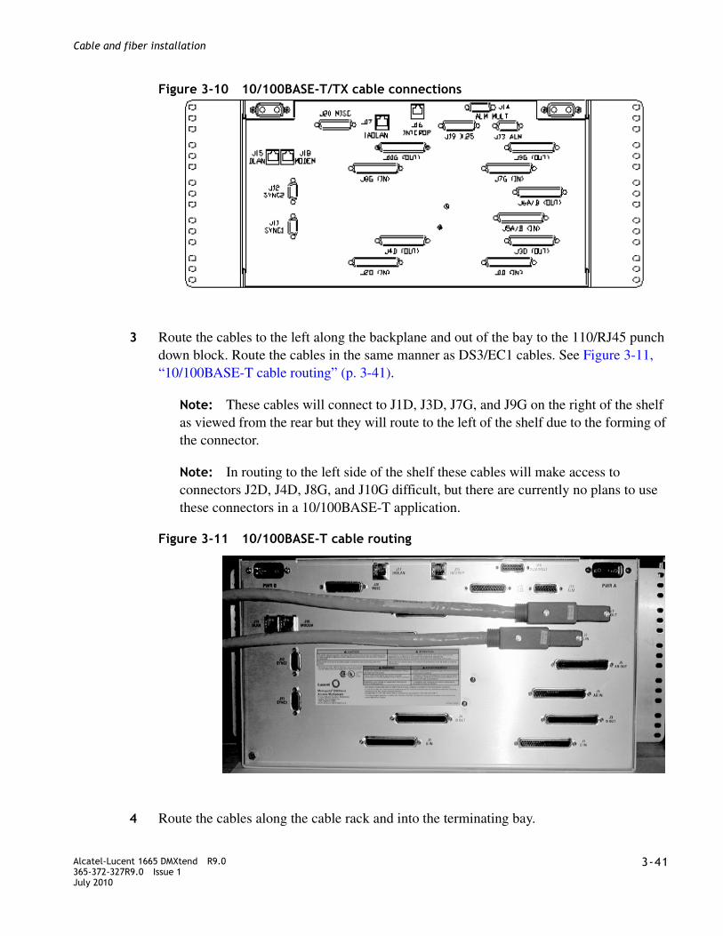
........................................................................................................................................................................Alcatel-Lucent 1665 DMXtend R9.0365-372-327R9.0 Issue 1July 2010
3-41
........................................................................................................................................................................
Cable and fiber installation
Figure 3-10 10/100BASE-T/TX cable connections
................................................................................................................................................
3 Route the cables to the left along the backplane and out of the bay to the 110/RJ45 punch down block. Route the cables in the same manner as DS3/EC1 cables. See Figure 3-11, “10/100BASE-T cable routing” (p. 3-41).
Note: These cables will connect to J1D, J3D, J7G, and J9G on the right of the shelf as viewed from the rear but they will route to the left of the shelf due to the forming of the connector.
Note: In routing to the left side of the shelf these cables will make access to connectors J2D, J4D, J8G, and J10G difficult, but there are currently no plans to use these connectors in a 10/100BASE-T application.
Figure 3-11 10/100BASE-T cable routing
................................................................................................................................................
4 Route the cables along the cable rack and into the terminating bay.

........................................................................................................................................................................3-42 Alcatel-Lucent 1665 DMXtend R9.0
365-372-327R9.0 Issue 1July 2010
........................................................................................................................................................................
Cable and fiber installation
................................................................................................................................................
5 Cut cable to length and punch down cable to the 110 block. See Table 3-11, “10/100BaseT Ethernet connections” (p. 3-43) for pin out assignments.
................................................................................................................................................
6 Check off the appropriate box in the Table I-2, Installation checklist.
........................................................................................................................................................E N D O F S T E P S
Table 3-10 10/100Base-T Ethernet cable assemblies
CAUTIONThe LNW66 and LNW74 10/100 BaseT-Ethernet pack does not have lightning protection for the metallic connections. Therefore it is necessary to use a lightning protected patch panel, such as the Black Box CAT5 protected patch panel JSM110A, for intra-office applications only.
DescriptionCable assembly #
Cable length(feet)
Alcatel-Lucent 1665 DMXtend backplane connections
10/100BASE-T/TX Ethernet cable
848819090 8 J1D, J3D, J7G, and J9G
848778114 20
848923280 35
848778122 50
848923298 75
848778106 100
848923306 125
848778148 150
848923314 175
848923322 200
848923330 225
848923348 250
848923355 275
848778130 300

........................................................................................................................................................................Alcatel-Lucent 1665 DMXtend R9.0365-372-327R9.0 Issue 1July 2010
3-43
........................................................................................................................................................................
Cable and fiber installation
Table 3-11 10/100BaseT Ethernet connections
Port# (1-24)Wire color
dsub 62M pin# Signal
RJ-45 pin#J1D, J7G J3D, J9G
13 1 W/O 50/49 R+/R- 1/2
W/BL 8/29 T+/T- 3/6
14 2 W/BR 48/47 R+/R- 1/2
W/G 5/26 T+/T- 3/6
15 3 R/BL 7/28 R+/R- 1/2
W/S 6/27 T+/T- 3/6
16 4 R/G 46/45 R+/R- 1/2
R/O 4/25 T+/T- 3/6
17 5 R/S 56/55 R+/R- 1/2
R/BR 13/34 T+/T- 3/6
18 6 BK/O 11/32 R+/R- 1/2
BK/BL 10/31 T+/T- 3/6
19 7 BK/BR 54/53 R+/R- 1/2
BK/G 12/33 T+/T- 3/6
20 8 Y/BL 52/51 R+/R- 1/2
BK/S 9/30 T+/T- 3/6
21 9 Y/G 19/40 R+/R- 1/2
Y/O 18/39 T+/T- 3/6
22 10 Y/S 58/57 R+/R- 1/2
Y/BR 16/37 T+/T- 3/6
23 11 V/O 60/59 R+/R- 1/2
V/BL 17/38 T+/T- 3/6
24 12 V/BR 15/36 R+/R- 1/2
V/G 14/35 T+/T- 3/6
Notes: 1. 10/100BASE-T/TX ethernet cables have transmit and receive on the
same cable.

........................................................................................................................................................................3-44 Alcatel-Lucent 1665 DMXtend R9.0
365-372-327R9.0 Issue 1July 2010
........................................................................................................................................................................
Cable and fiber installation
IAO LAN and TCP/IP cable installation
Description
This section describes how to connect the IAO LAN/TCP-IP (LAN 10BASE-T) cable to the Alcatel-Lucent 1665 DMXtend shelf and to the interfacing equipment. Perform this procedure if this cabling is required.
Alcatel-Lucent 1665 DMXtend supports an IntraOffice LAN (IAO LAN) interface for operations data communications to support operations systems such as the Navis® Optical EMS (formerly WaveStar® SNMS).
Since the IAO LAN can be provisioned as an extension of the SONET DCC, the IAO LAN can also be used to join multiple, otherwise separate subnetworks.
All NE-to-NE OI features that are supported over the DCC are also supported over the IAO LAN.
The IAO LAN/TCP-IP interface cable is available in two configurations (cross-over and straight-through) and may be connected to either the front or rear of the Alcatel-Lucent 1665 DMXtend shelf. The following tables provide additional information:
• Table 3-12, “LAN 10BaseT cable assemblies” (p. 3-45)
• Table 3-14, “LAN 10Base-T straight-through cable connections” (p. 3-47)
• Table 3-13, “LAN 10Base-T cross-over cable connections” (p. 3-47)
Steps
................................................................................................................................................
1 If connecting directly to a PC, use a LAN 10BASE-T Cross-over Cable Assembly [see Table 3-12, “LAN 10BaseT cable assemblies” (p. 3-45)].
If connecting to a hub, use a LAN 10BASE-T Straight-through Cable Assembly [see Table 3-13, “LAN 10Base-T cross-over cable connections” (p. 3-47)].
................................................................................................................................................
2 If connecting to the front of the Alcatel-Lucent 1665 DMXtend shelf, connect the cable to the LAN (RJ45) jack on the SYSCTL circuit pack.
If connecting to the rear of the Alcatel-Lucent 1665 DMXtend shelf, connect the cable to the J17 port (IAO LAN) on the Alcatel-Lucent 1665 DMXtend backplane and route to the left side of the shelf. See Figure 3-12, “IAO LAN/TCP-IP cable connection to rear of Alcatel-Lucent 1665 DMXtend” (p. 3-45).

........................................................................................................................................................................Alcatel-Lucent 1665 DMXtend R9.0365-372-327R9.0 Issue 1July 2010
3-45
........................................................................................................................................................................
Cable and fiber installation
Figure 3-12 IAO LAN/TCP-IP cable connection to rear of Alcatel-Lucent 1665 DMXtend
................................................................................................................................................
3 If a cross-over cable is used, route the cable to the desired PC LAN port.
If a straight-through cable is used, route the cable to the desired hub port location.
................................................................................................................................................
4 Check off the appropriate box in the Table I-2, Installation checklist.
........................................................................................................................................................E N D O F S T E P S
Table 3-12 LAN 10BaseT cable assemblies
DescriptionCable assembly #
Cable length (feet)
Alcatel-Lucent 1665 DMXtend connections
Front Rear
LAN 10BASE-T Cross-over cable to PC / CIT
109321810 10 SYSCTLLAN jack
J17 (IAO LAN)
848605028 50
848605036 100
848605051 150
848605069 200
848605077 300

........................................................................................................................................................................3-46 Alcatel-Lucent 1665 DMXtend R9.0
365-372-327R9.0 Issue 1July 2010
........................................................................................................................................................................
Cable and fiber installation
LAN 10BASE-T Straight-through cable to Ethernet hub / router
109321836 20 SYSCTLLAN jack
J17 (IAO LAN)
109321844 30
109321851 40
848604948 50
109321869 60
109321877 70
109321885 80
109321893 90
848604955 100
109321901 110
109321919 120
109321927 130
109321935 140
848604963 150
109321943 160
109321950 180
848604971 200
109321968 220
109321976 240
109321984 260
109321992 280
848604997 300
DescriptionCable assembly #
Cable length (feet)
Alcatel-Lucent 1665 DMXtend connections
Front Rear

........................................................................................................................................................................Alcatel-Lucent 1665 DMXtend R9.0365-372-327R9.0 Issue 1July 2010
3-47
........................................................................................................................................................................
Cable and fiber installation
Table 3-13 LAN 10Base-T cross-over cable connections
Table 3-14 LAN 10Base-T straight-through cable connections
Modem cable installation
Description
The use of a modem will allow the Alcatel-Lucent 1665 DMXtend to be accessed remotely via dial up.
Note: Perform this procedure for the shelf which will be directly connected to a modem or a distribution frame (if specified in the order).
Steps
................................................................................................................................................
1 Obtain the modem cable per Table 3-15, “Modem cable assemblies” (p. 3-48). Connect the RJ45 end of the modem cable to the MODEM port (J18) of Alcatel-Lucent 1665 DMXtend shelf and route it to the left side of the shelf. (See Figure 3-13, “Modem cable connection” (p. 3-48).
Connection
Alcatel-Lucent 1665 DMXtend bkpl Color
Otherside
J17 (IAO LAN) 1 BL - W 3
2 W - BL 6
3 O - W 1
6 W - O 2
Connection
Alcatel-Lucent 1665 DMXtend bkpl Color
Otherside
J17 (IAO LAN) 1 BL - W 1
2 W - BL 2
3 O - W 3
6 W - O 6
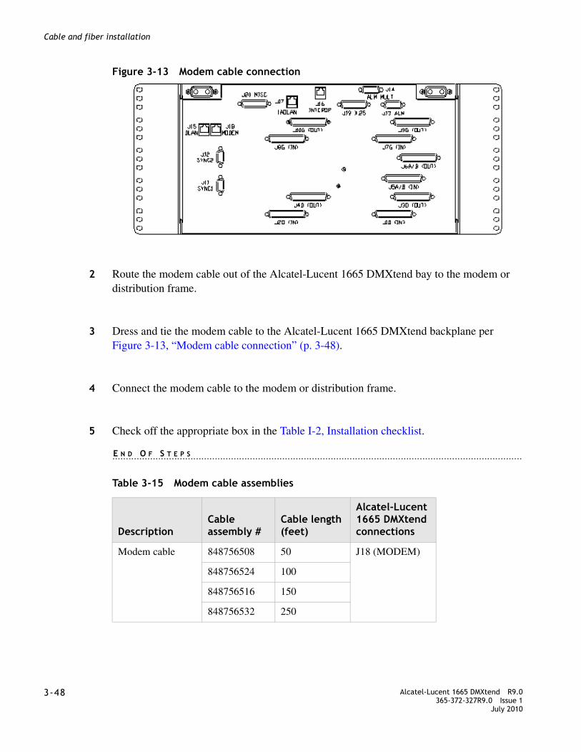
........................................................................................................................................................................3-48 Alcatel-Lucent 1665 DMXtend R9.0
365-372-327R9.0 Issue 1July 2010
........................................................................................................................................................................
Cable and fiber installation
Figure 3-13 Modem cable connection
................................................................................................................................................
2 Route the modem cable out of the Alcatel-Lucent 1665 DMXtend bay to the modem or distribution frame.
................................................................................................................................................
3 Dress and tie the modem cable to the Alcatel-Lucent 1665 DMXtend backplane per Figure 3-13, “Modem cable connection” (p. 3-48).
................................................................................................................................................
4 Connect the modem cable to the modem or distribution frame.
................................................................................................................................................
5 Check off the appropriate box in the Table I-2, Installation checklist.
........................................................................................................................................................E N D O F S T E P S
Table 3-15 Modem cable assemblies
DescriptionCable assembly #
Cable length (feet)
Alcatel-Lucent 1665 DMXtend connections
Modem cable 848756508 50 J18 (MODEM)
848756524 100
848756516 150
848756532 250
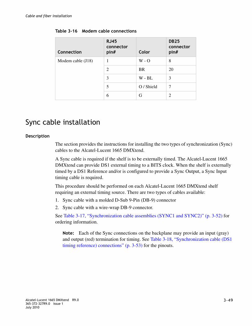
........................................................................................................................................................................Alcatel-Lucent 1665 DMXtend R9.0365-372-327R9.0 Issue 1July 2010
3-49
........................................................................................................................................................................
Cable and fiber installation
Table 3-16 Modem cable connections
Sync cable installation
Description
The section provides the instructions for installing the two types of synchronization (Sync) cables to the Alcatel-Lucent 1665 DMXtend.
A Sync cable is required if the shelf is to be externally timed. The Alcatel-Lucent 1665 DMXtend can provide DS1 external timing to a BITS clock. When the shelf is externally timed by a DS1 Reference and/or is configured to provide a Sync Output, a Sync Input timing cable is required.
This procedure should be performed on each Alcatel-Lucent 1665 DMXtend shelf requiring an external timing source. There are two types of cables available:
1. Sync cable with a molded D-Sub 9-Pin (DB-9) connector
2. Sync cable with a wire-wrap DB-9 connector.
See Table 3-17, “Synchronization cable assemblies (SYNC1 and SYNC2)” (p. 3-52) for ordering information.
Note: Each of the Sync connections on the backplane may provide an input (gray) and output (red) termination for timing. See Table 3-18, “Synchronization cable (DS1 timing reference) connections” (p. 3-53) for the pinouts.
Connection
RJ45 connector pin# Color
DB25 connector pin#
Modem cable (J18) 1 W - O 8
2 BR 20
3 W - BL 3
5 O / Shield 7
6 G 2
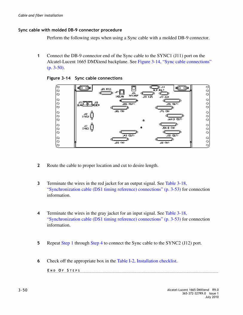
........................................................................................................................................................................3-50 Alcatel-Lucent 1665 DMXtend R9.0
365-372-327R9.0 Issue 1July 2010
........................................................................................................................................................................
Cable and fiber installation
Sync cable with molded DB-9 connector procedure
Perform the following steps when using a Sync cable with a molded DB-9 connector.
................................................................................................................................................
1 Connect the DB-9 connector end of the Sync cable to the SYNC1 (J11) port on the Alcatel-Lucent 1665 DMXtend backplane. See Figure 3-14, “Sync cable connections” (p. 3-50).
Figure 3-14 Sync cable connections
................................................................................................................................................
2 Route the cable to proper location and cut to desire length.
................................................................................................................................................
3 Terminate the wires in the red jacket for an output signal. See Table 3-18, “Synchronization cable (DS1 timing reference) connections” (p. 3-53) for connection information.
................................................................................................................................................
4 Terminate the wires in the gray jacket for an input signal. See Table 3-18, “Synchronization cable (DS1 timing reference) connections” (p. 3-53) for connection information.
................................................................................................................................................
5 Repeat Step 1 through Step 4 to connect the Sync cable to the SYNC2 (J12) port.
................................................................................................................................................
6 Check off the appropriate box in the Table I-2, Installation checklist.
........................................................................................................................................................E N D O F S T E P S

........................................................................................................................................................................Alcatel-Lucent 1665 DMXtend R9.0365-372-327R9.0 Issue 1July 2010
3-51
........................................................................................................................................................................
Cable and fiber installation
Sync cable with wire-wrap DB-9 connector procedure
Perform the following steps when using the Sync cable with the wire-wrap DB-9 connector.
................................................................................................................................................
1 Connect the wire-wrap DB-9 connector to SYNC1 (J11). See Figure 3-14, “Sync cable connections” (p. 3-50).
................................................................................................................................................
2 Wire-wrap Rx1 and Tx1 (red cable) on the D-Sub connector for an output signal per Table 3-18, “Synchronization cable (DS1 timing reference) connections” (p. 3-53).
................................................................................................................................................
3 Wire-wrap Rx2 and Tx2 (gray cable) on the D-Sub connector for an input signal per Table 3-18, “Synchronization cable (DS1 timing reference) connections” (p. 3-53)
................................................................................................................................................
4 Route the cable to proper location and cut to desire length.
................................................................................................................................................
5 Terminate the other end to a clock source or equipment. See Table 3-18, “Synchronization cable (DS1 timing reference) connections” (p. 3-53) for connection information.
................................................................................................................................................
6 Repeat Step 1 through Step 5 for SYNC2 (J12) connection.
................................................................................................................................................
7 Check off the appropriate box in the Table I-2, Installation checklist.
........................................................................................................................................................E N D O F S T E P S

........................................................................................................................................................................3-52 Alcatel-Lucent 1665 DMXtend R9.0
365-372-327R9.0 Issue 1July 2010
........................................................................................................................................................................
Cable and fiber installation
Table 3-17 Synchronization cable assemblies (SYNC1 and SYNC2)
DescriptionCable assembly #
Cable length (feet)
Alcatel-Lucent 1665 DMXtend backplane connections
Sync1 (J11) and Sync2 (J12) cables, straight connector,
DS1 timing reference for DS1 external Sync In/Out timing 2 cables per code.
848839619 50 J11 (Sync1)/J12 (Sync2)
848923363 75
848839627 100
848923371 125
848839635 150
848923389 175
848923439 200
848923447 225
848839643 250
848923454 275
848923462 300
848839650 450
Customer specific Sync1 (J11) and Sync2 (J12)
Sync input signal only, with filter connectors, 2 cables per code, with wire-wrap terminals and covers, as required by the customer.
848929311 50
848929329 100
848929337 150
848929345 250
848929352 450 J11 (Sync1)/J12 (Sync2)
Customer specific Sync1 (J11) and Sync2 (J12) cable harness, with filter connectors,
848631255 50
Two cables taped together as one harness per code, with wire wrap terminals and covers, as required by the customer.
848631271 100
848631289 150
848631297 250
848631305 450

........................................................................................................................................................................Alcatel-Lucent 1665 DMXtend R9.0365-372-327R9.0 Issue 1July 2010
3-53
........................................................................................................................................................................
Cable and fiber installation
Table 3-18 Synchronization cable (DS1 timing reference) connections
Office alarm cable installation
Description
Office alarms are the common method used in a central office for maintenance personnel to quickly isolate a failure. Perform this procedure if connection to the office alarm system is required.
Note: The office alarm relay contacts are rated at 50 VA which means that they are capable of switching 1 amp at 50 volts, or 2 amps at 25 volts. Their ability to switch large transient currents means that they can, if necessary, switch up to ten 5-watt aisle pilot lamps.
If transient voltages or currents are above these limits, transient noise-suppressing devices such as diodes or contact protection networks must be used to keep within the voltage and current limits. If these protection devices are not sufficient, an external buffer relay MUST be provided.
Notes: 1. The Sync cable is 22 gauge.
2. Ground the Filter connectors either at the bay frame ground or at the office timing source. See office records.
DescriptionCable assembly #
Cable length (feet)
Alcatel-Lucent 1665 DMXtend backplane connections
Conn. Jacket Color9-pin conn.
Special conn. Designation Name
Sync1 (J11)/Sync2 (J12)
Red BL 1 Rx1 RGO1/RGO2 Sync Output
W 6 Tx1 TPO1/TPO2
Gray BL 2 Rx2 RGI1/RGI2 Sync Input
W 7 Tx2 TPI1/TPI2
Drain 5 GND GRD

........................................................................................................................................................................3-54 Alcatel-Lucent 1665 DMXtend R9.0
365-372-327R9.0 Issue 1July 2010
........................................................................................................................................................................
Cable and fiber installation
In all cases, and as a matter of good practice, suppression devices such as diodes or contact protection networks must be provided across any external relay coil being driven by the Alcatel-Lucent 1665 DMXtend to limit transient voltages and currents.
Office alarm cable assemblies are listed in Table 3-19, “Office alarm cable assemblies” (p. 3-57).
Alarm mult
Office alarm cabling in a Alcatel-Lucent 1665 DMXtend bay starts at the bottom shelf which is cabled directly to the office alarm system. Then as shelves are added to the bay, the office alarm connection is extended by multing the alarm cabling from shelf to shelf (bottom to top). Alarm mults do not leave the bay.
For example, J13 of one shelf should be connected to the office alarm terminal. J14 of the same shelf should be connected to J13 of the shelf above shelf and the same procedure should be continued to connect more shelves.

........................................................................................................................................................................Alcatel-Lucent 1665 DMXtend R9.0365-372-327R9.0 Issue 1July 2010
3-55
........................................................................................................................................................................
Cable and fiber installation
Steps
................................................................................................................................................
1 Obtain the office alarm cable per Table 3-19, “Office alarm cable assemblies” (p. 3-57). Connect the office alarm cable to ALM (J13) of the bottom Alcatel-Lucent 1665 DMXtend shelf. See Figure 3-15, “Office alarm cable connections” (p. 3-55).
Figure 3-15 Office alarm cable connections
................................................................................................................................................
2 Route the office alarm cable from the bottom shelf out of the Alcatel-Lucent 1665 DMXtend bay per Figure 3-16, “Office alarm cable routing” (p. 3-55) to the office alarm panel.
Figure 3-16 Office alarm cable routing
................................................................................................................................................
3 Inspect the office alarm panel and add a contact protection network (if required).
................................................................................................................................................
4 Cut the office alarm cable to the desired length.

........................................................................................................................................................................3-56 Alcatel-Lucent 1665 DMXtend R9.0
365-372-327R9.0 Issue 1July 2010
........................................................................................................................................................................
Cable and fiber installation
................................................................................................................................................
5 Wire-wrap the loose end of the office alarm cable to the alarm panel, making connections as listed in Table 3-19, “Office alarm cable assemblies” (p. 3-57).
Alarm Mult
The following steps should be performed when the bottom shelf in the bay will be directly connected to the office alarms. The cable added in this procedure is to mult office alarms in a bay to the bottom shelf. In this procedure the bottom shelf is multed to the shelf immediately above. That shelf is then multed to the shelf above it. Continue until the top shelf is connected.
Note: In order for office alarms in a shelf (other than the bottom shelf) to be reported, all office alarm cable mults from that shelf to the bottom shelf must be in place. No shelf should be skipped.
................................................................................................................................................
6 Obtain the office alarm mult cable 848589602 for Alcatel-Lucent 1665 DMXtend. Connect one end to ALM MULT (J14) of the Alcatel-Lucent 1665 DMXtend shelf. See Figure 3-15, “Office alarm cable connections” (p. 3-55).
................................................................................................................................................
7 Route the office alarm mult cable to the side of the bay and connect it to ALM (J13) of the Alcatel-Lucent 1665 DMXtend shelf above.See Figure 3-16, “Office alarm cable routing” (p. 3-55).
................................................................................................................................................
8 Repeat this procedure for each shelf in the bay (stopping at the top).
................................................................................................................................................
9 Check off the appropriate box in the Table I-2, Installation checklist.
........................................................................................................................................................E N D O F S T E P S

........................................................................................................................................................................Alcatel-Lucent 1665 DMXtend R9.0365-372-327R9.0 Issue 1July 2010
3-57
........................................................................................................................................................................
Cable and fiber installation
Table 3-19 Office alarm cable assemblies
Table 3-20 Alarm office connections
DescriptionCable assembly #
Cable length (feet)
Alcatel-Lucent 1665 DMXtend backplane connections
Office Alarm Cable 848558193 50 J13
848562286 100
848562294 150
848562302 250
Office Alarm Mult Cable 848589602 3 J14 to J13
Office Alarm Mult Cable to Lambda Unite
848861530
848861530
3
3
J14
J13
Conn. Pin# Color Designation Name
J13-J14 1
2
3
4
BL-W
W-BL
O-W
W-O
RYMJV1
RYMJV2
RYMJA1
RYMJA2
Major Alarm Visible
Major Alarm Visible Return
Major Alarm Audible
Major Alarm Audible Return
5
6
7
8
G-W
W-G
BR-W
W-BR
RYMNV1
RYMNV2
RYMNA1
RYMNA2
Minor Alarm Visible
Minor Alarm Visible Return
Minor Alarm Audible
Minor Alarm Audible Return
9
10
11
12
S-W
W-S
BL-R
R-BL
RYCRV1
RYCRV2
RYCRA1
RYCRA2
Critical Alarm Visible
Critical Alarm Visible Return
Critical Alarm Audible
Critical Alarm Audible Return
Notes: 1. The SYSCTL circuit pack reports office alarms.
2. The connection to the central office alarms from P13 is run for each Alcatel-Lucent 1665 DMXtend shelf assembly when used in a miscellaneously mounted individual application or from the first Alcatel-Lucent 1665 DMXtend shelf assembly when mounted in a typical bay arrangement.

........................................................................................................................................................................3-58 Alcatel-Lucent 1665 DMXtend R9.0
365-372-327R9.0 Issue 1July 2010
........................................................................................................................................................................
Cable and fiber installation
Miscellaneous (environmental) discrete telemetry cable installation
Description
The miscellaneous (environmental) discrete telemetry access allows the maintenance center to control and monitor equipment collocated with the Alcatel-Lucent 1665 DMXtend.
The environmental control feature enables the maintenance center to remotely initiate up to four contact closures at the remote terminal (RT) for equipment operation such as pumps, generators, etc.
The environmental alarm status indications allow up to 18 miscellaneous user-settable alarm status indications (SI) at the remote terminal for transmission toward the central office.
Miscellaneous (environmental) discrete telemetry cable assemblies and the length options are listed in Table 3-21, “Miscellaneous discrete cable assemblies” (p. 3-61).
Steps
This procedure is performed for Alcatel-Lucent 1665 DMXtend shelves requiring miscellaneous (environmental) discrete telemetry.
................................................................................................................................................
1 Connect the miscellaneous discrete telemetry cable to the J20 MISC connector on the backplane of the Alcatel-Lucent 1665 DMXtend shelf per Figure 3-17, “Miscellaneous discrete cable connection” (p. 3-59).

........................................................................................................................................................................Alcatel-Lucent 1665 DMXtend R9.0365-372-327R9.0 Issue 1July 2010
3-59
........................................................................................................................................................................
Cable and fiber installation
Figure 3-17 Miscellaneous discrete cable connection
................................................................................................................................................
2 Route the cable out of the Alcatel-Lucent 1665 DMXtend bay per Figure 3-18, “Miscellaneous discrete cable routing” (p. 3-59) to the telemetry panel.
Figure 3-18 Miscellaneous discrete cable routing
................................................................................................................................................
3 Cut the miscellaneous (environmental) discrete telemetry cable to the desired length at the telemetry panel.
................................................................................................................................................
4 Wire-wrap the loose end of the miscellaneous (environmental) discrete telemetry cable to the wire-wrap terminal strip, making connections per Table 3-21, “Miscellaneous discrete cable assemblies” (p. 3-61).
Note: Each miscellaneous (environmental) discrete telemetry designation is connected to the Alcatel-Lucent 1665 DMXtend by two leads (wires). For each input, one lead should be connected to input-common and the other lead

........................................................................................................................................................................3-60 Alcatel-Lucent 1665 DMXtend R9.0
365-372-327R9.0 Issue 1July 2010
........................................................................................................................................................................
Cable and fiber installation
should be connected to the appropriate alarm indication. For each output, one lead should be connected to output-common and the other lead should be connected to the appropriate alarm indication.
................................................................................................................................................
5 Check off the appropriate box in the Table I-2, Installation checklist.
........................................................................................................................................................E N D O F S T E P S

........................................................................................................................................................................Alcatel-Lucent 1665 DMXtend R9.0365-372-327R9.0 Issue 1July 2010
3-61
........................................................................................................................................................................
Cable and fiber installation
Table 3-21 Miscellaneous discrete cable assemblies
Table 3-22 Miscellaneous (environmental) discrete telemetry connections
DescriptionCable assembly #
Cable length (feet)
Alcatel-Lucent 1665 DMXtend backplane connections
Miscellaneous discrete cable
848979399 15
848979407 30
848549598 50 J20
848549606 100
848549614 150
848549622 250
848549630 350
Conn. Pin# Color Designation Name
J20 1
2
3
4
BL-W
W-BL
O-W
W-O
TLMI1
TLMI2
TLMI3
TLMI4
Env. Input - #1
Env. Input - #2
Env. Input - #3
Env. Input - #4
5
6
7
8
G-W
W-G
BR-W
W-BR
TLMI5
TLMI6
TLMI7
TLMI8
Env. Input - #5
Env. Input - #6
Env. Input - #7
Env. Input - #8
9
10
11
12
S-W
W-S
BL-R
R-BL
TLMI9
TLMI10
TLMI11
TLMI12
Env. Input - #9
Env. Input - #10
Env. Input - #11
Env. Input - #12
13
14
15
16
O-R
R-O
G-R
R-G
TLMI13
TLMI14
TLMI15
TLMI16
Env. Input - #13
Env. Input - #14
Env. Input - #15
Env. Input - #16

........................................................................................................................................................................3-62 Alcatel-Lucent 1665 DMXtend R9.0
365-372-327R9.0 Issue 1July 2010
........................................................................................................................................................................
Cable and fiber installation
OC-3/OC-12/OC-48/OC-192 main optical fiber cable installation
Description
This section describes how to route the optical fiber cables from the interconnecting equipment (for example, an LGX® optical fiber distributing frame) to the OC-3/OC-12/OC-48/OC-192 Main OLIUs of the Alcatel-Lucent 1665 DMXtend. This procedure does not cover routing the optical fiber cable between sites.
The optical fiber cables will be connected to the Alcatel-Lucent 1665 DMXtend after the circuit packs are installed. The Alcatel-Lucent 1665 DMXtend requires single-mode fiber for the main OLIUs.
Note: The optical fiber cable is fragile and must be protected. The fibers should be placed in a protective tube or channel, such as PVC tubing, or PANDUIT cable channel, when running the cable from the Alcatel-Lucent 1665 DMXtend to the cable rack. The fibers should be placed in the cable rack in a protective channel with nothing on top of them. Cable ties should NOT be used with the optical fiber cables.
Unterminated optical connectors may emit laser radiation. Do not view an unterminatedoptical connector with optical instruments
17
18
19
20
BR-R
R-BR
S-R
R-S
TLMI17
TLMI18
TLMI19
TLMIC48VTRN
Env. Input - #17
Env. Input - #18
Env. Input - #19
Input Common
21
22
23
24
25
BL-BK
BK-BL
O-BK
BK-O
G-BK
TLMO1
TLMO2
TLMO3
TLMO4
TLMOC
Env. Output - #1
Env. Output - #2
Env. Output - #3
Env. Output - #4
Output Common
Conn. Pin# Color Designation Name
WARNING
Laser hazard

........................................................................................................................................................................Alcatel-Lucent 1665 DMXtend R9.0365-372-327R9.0 Issue 1July 2010
3-63
........................................................................................................................................................................
Cable and fiber installation
Invisible laser radiation exists when unterminated. Avoid direct exposure of the eyes to the beam.
Note: Prior to connecting the optical fiber cables, the fibers should be examined to ensure that they are clean. See Appendix A, “Fiber cleaning” for recommended cleaning procedures.
WARNING
Laser hazard
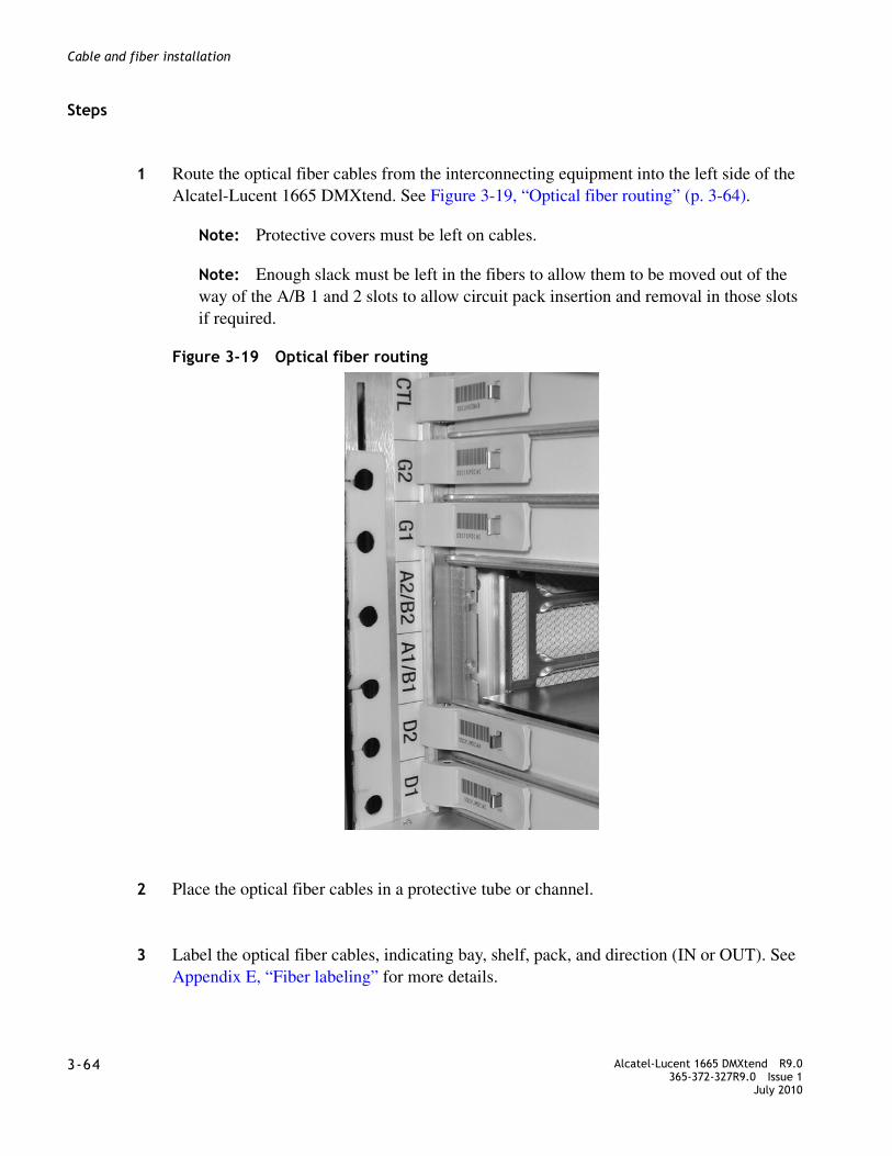
........................................................................................................................................................................3-64 Alcatel-Lucent 1665 DMXtend R9.0
365-372-327R9.0 Issue 1July 2010
........................................................................................................................................................................
Cable and fiber installation
Steps
................................................................................................................................................
1 Route the optical fiber cables from the interconnecting equipment into the left side of the Alcatel-Lucent 1665 DMXtend. See Figure 3-19, “Optical fiber routing” (p. 3-64).
Note: Protective covers must be left on cables.
Note: Enough slack must be left in the fibers to allow them to be moved out of the way of the A/B 1 and 2 slots to allow circuit pack insertion and removal in those slots if required.
Figure 3-19 Optical fiber routing
................................................................................................................................................
2 Place the optical fiber cables in a protective tube or channel.
................................................................................................................................................
3 Label the optical fiber cables, indicating bay, shelf, pack, and direction (IN or OUT). See Appendix E, “Fiber labeling” for more details.
........................................................................................................................................................................Alcatel-Lucent 1665 DMXtend R9.0365-372-327R9.0 Issue 1July 2010
3-65
........................................................................................................................................................................
Cable and fiber installation
................................................................................................................................................
4 Check off the appropriate box in the Table I-2, Installation checklist.
........................................................................................................................................................E N D O F S T E P S
OC-3/OC-12/OC-48 low-speed optical fiber cable installation
Description
This section describes how to route the single-mode fiber optical cables from the interconnecting equipment (for example, an LGX® optical fiber distributing frame) to the Alcatel-Lucent 1665 DMXtend OC-3/OC-12/OC-48 optical ports. This procedure does not cover routing the optical fiber cable between sites.
The optical fiber cables will be connected to the OC-3/OC-12/OC-48 optical ports after the circuit packs are installed.
Note: The optical fiber cable is fragile and must be protected. The fibers should be placed in a protective tube or channel, such as PVC tubing, or PANDUIT cable channel, when running the cable from the Alcatel-Lucent 1665 DMXtend to the cable rack. The fibers should be placed in the cable rack in a protective channel with nothing on top of them. Cable ties should NOT be used with the optical fiber cables.
Unterminated optical connectors may emit laser radiation. Do not view an unterminated optical connector with optical instruments.
Invisible laser radiation exists when unterminated. Avoid direct exposure of the eyes to the beam.
Note: Prior to connecting the optical fiber cables, the fibers should be examined to ensure that they are clean. See Appendix A, “Fiber cleaning” for recommended cleaning procedures.
WARNING
Laser hazard
WARNING
Laser hazard
........................................................................................................................................................................3-66 Alcatel-Lucent 1665 DMXtend R9.0
365-372-327R9.0 Issue 1July 2010
........................................................................................................................................................................
Cable and fiber installation
Steps
................................................................................................................................................
1 See the engineering job specification. Determine the function slot where the pack will be inserted. The OC-3/OC-12/OC-48 pack can be inserted into either the D or G function slots.
................................................................................................................................................
2 Label the optical fiber cables, indicating bay, shelf, function group, pack, and direction (IN or OUT).
................................................................................................................................................
3 Route optical fiber cables from the interconnecting equipment into the left side of the Alcatel-Lucent 1665 DMXtend and into the OC-3/OC-12/OC-48 optical ports. See Figure 3-19, “Optical fiber routing” (p. 3-64).
................................................................................................................................................
4 Place the optical fiber cables in a protective tube or channel.
................................................................................................................................................
5 Check off the appropriate box in the Table I-2, Installation checklist.
........................................................................................................................................................E N D O F S T E P S
100/1000BASE-X optical fiber cable installation
Description
This section describes how to route the 100/1000BASE-X optical fiber cables from the interconnecting equipment (for example, an LGX® optical fiber distributing frame) to the 100/1000BASE-X optical ports. The LNW63, LNW64, and LNW170 single mode or multimode fiber can be used depending on the SFP provided with the work order.
Note: The optical fiber cable is fragile and must be protected. The fibers should be placed in a protective tube or channel, such as PVC tubing, or PANDUIT cable channel, when running the cable from the Alcatel-Lucent 1665 DMXtend to the cable rack. The fibers should be placed in the cable rack in a protective channel with nothing on top of them. Cable ties should NOT be used with the optical fiber cables.
........................................................................................................................................................................Alcatel-Lucent 1665 DMXtend R9.0365-372-327R9.0 Issue 1July 2010
3-67
........................................................................................................................................................................
Cable and fiber installation
Unterminated optical connectors may emit laser radiation. Do not view an unterminated optical connector with optical instruments.
Invisible laser radiation exists when unterminated. Avoid direct exposure of the eyes to the beam.
Note: Prior to connecting the optical fiber cables, the fibers should be examined to ensure that they are clean. See Appendix A, “Fiber cleaning” for recommended cleaning procedures.
WARNING
Laser hazard
WARNING
Laser hazard

........................................................................................................................................................................3-68 Alcatel-Lucent 1665 DMXtend R9.0
365-372-327R9.0 Issue 1July 2010
........................................................................................................................................................................
Cable and fiber installation
Steps
................................................................................................................................................
1 See the engineering job specification. Determine the function slot that the pack will be inserted. If equipped with the VLF mains (LNW141 or LNW84) the 100/1000BASE-X pack can be inserted into any function slots D1, D2, G1 or G2. Otherwise, if equipped with the non-VLF mains the 100/1000BASE-X pack can be inserted only into function slots D1 or G1.
................................................................................................................................................
2 Label the optical fiber cables, indicating bay, shelf, function group, pack, and direction (IN or OUT).
................................................................................................................................................
3 Route optical fiber cables from the interconnecting equipment into the left side of the Alcatel-Lucent 1665 DMXtend and into the 100/1000BASE-X optical ports. See Table 3-19, “Optical fiber routing” (p. 3-64).
................................................................................................................................................
4 Place the optical fiber cables in a protective tube or channel.
................................................................................................................................................
5 Check off the appropriate box in the Table I-2, Installation checklist.
........................................................................................................................................................E N D O F S T E P S
CIT (RS-232) cable installation
Description
This section provides the procedure to connect the CIT (RS-232) cable from the LNW2 (SYSCTL) to a PC (serial port). This will allow communications between the PC and the RS-232 port located on the LNW2.
CIT cable assemblies and the length options are listed in Table 3-23, “CIT Cable Assembly” (p. 3-69).
Steps
................................................................................................................................................
1 Connect the RJ45 end of the CIT cable to the RS-232 jack located on the LNW2 (SYSCTL).

........................................................................................................................................................................Alcatel-Lucent 1665 DMXtend R9.0365-372-327R9.0 Issue 1July 2010
3-69
........................................................................................................................................................................
Cable and fiber installation
................................................................................................................................................
2 Connect the 9-pin D-type connector to the serial port on the PC.
................................................................................................................................................
3 Check off the appropriate box in the Table I-2, Installation checklist.
........................................................................................................................................................E N D O F S T E P S
Table 3-23 CIT Cable Assembly
Table 3-24 Standard CIT cable connection
DescriptionCable assembly #
Cable length
Alcatel-Lucent 1665 DMXtendconnections
Front CIT cable
848748869 8 feet CIT/RS-232 jack on System Controller (LNW2)
Connection
RJ45 Connector
Color
9-Pin D-type connector
Pin# Designation Pin# Designation
Front CIT cable
1 FRS232N W - O 6 DCE Ready
3 FDTR W - BL 4 DTE Ready
4 Ground W - G 5 Ground
5 FTXD O 2 Receive Data
6 FRXD G 3 Transmit Data
Notes: 1. The connection and the colors shown above are for a standard Alcatel-Lucent
made cable. If you use a RJ-45 to DB-9 connector with a standard straight-through 10BASE-T LAN cable then, see Table 3-25, “RJ-45 to DB-9 connector connections” (p. 3-70).

........................................................................................................................................................................3-70 Alcatel-Lucent 1665 DMXtend R9.0
365-372-327R9.0 Issue 1July 2010
........................................................................................................................................................................
Cable and fiber installation
Table 3-25 RJ-45 to DB-9 connector connections
Final operations
Description
Final check on cable installation.
Steps
................................................................................................................................................
1 Verify that all the cables are properly dressed/connected.
................................................................................................................................................
2 Verify that all cables are properly labeled.
................................................................................................................................................
3 Verify that designations where cables were wire-wrapped are properly labeled.
................................................................................................................................................
4 Verify that all the fibers are properly dressed/connected.
................................................................................................................................................
5 Verify that all fibers are properly labeled. See Appendix E, “Fiber labeling”.
From RJ45 connector
To DB-9 pin D-type connector
Pin# Color Pin#
1 Blue 6
3 Black 4
4 Red 5
5 Green 2
6 Yellow 3
Notes: 1. The connection and the colors shown above are for RJ-45 to
DB-9 connector.
2. This connector should be used with a standard straight-through 10BASE-T LAN cable.

........................................................................................................................................................................Alcatel-Lucent 1665 DMXtend R9.0365-372-327R9.0 Issue 1July 2010
3-71
........................................................................................................................................................................
Cable and fiber installation
................................................................................................................................................
6 Verify that designations where fibers were terminated are properly labeled.
................................................................................................................................................
7 Replace rear cover on shelf if ordered.
................................................................................................................................................
8 Check off the appropriate box in the Table I-2, Installation checklist.
........................................................................................................................................................E N D O F S T E P S

........................................................................................................................................................................3-72 Alcatel-Lucent 1665 DMXtend R9.0
365-372-327R9.0 Issue 1July 2010
........................................................................................................................................................................
Cable and fiber installation
4-1Alcatel-Lucent 1665 DMXtend R9.0365-372-327R9.0 Issue 1July 2010
............................................................................................................................................................................................................................................................
4 Circuit pack installation
Overview
Purpose
This section provides information for performing the following:
• Shelf powering
• Circuit pack option settings and installation.
Detailed information on the function of each circuit pack is contained in Alcatel-Lucent 1665 Data Multiplexer Extend (DMXtend) User Operations Guide 365-372-325
Contents
This chapter provides information on the following topics:
Description
Overview
This section should be performed on all shelf installations.
Description 4-1
Powering 4-2
Circuit pack compatibility 4-6
Initial circuit pack installation 4-9

............................................................................................................................................................................................................................................................4-2 Alcatel-Lucent 1665 DMXtend R9.0
365-372-327R9.0 Issue 1July 2010
............................................................................................................................................................................................................................................................
Circuit pack installation
Tools, test equipment, and accessories
Listed below are the tools, test equipment and accessories necessary to perform the procedures in this section.
Powering
Overview
The following table lists the requirements for the Alcatel-Lucent 1665 Data Multiplexer Extend (Alcatel-Lucent 1665 DMXtend) shelf.
Table 4-1 Alcatel-Lucent 1665 DMXtend shelf power supply requirements
Quantity Description Comments
Screwdriver(s) A screwdriver(s) with the appropriate head(s) is (are) required for securing the mounting screws, repositioning the mounting brackets, installing the interfacing cables, and for setting the circuit breakers to the OFF position.
1 ESD Wrist Strap A wrist strap must be worn when handling circuit packs. Use the electrostatic discharge (ESD) jack provided on the shelf.
1 Multimeter (Optional) The voltmeter must be capable of measuring DC voltage in the 40- to 60-volt range. The use of the voltmeter is optional since the shelf will alarm or shut down if the proper voltage is not supplied.
1 Personal Computer (PC) Required to run the WaveStar® CIT software.
1 CIT RS-232 Interface Cable
8-ft. long RJ45 to 9-pin D-sub serial cable (Comcode 848748869). Required to connect the PC to the CIT jack on the front of the SYSCTL circuit pack.
Item Description
Voltage range, all components -40.0V to -60.0V DC
Power feeders Two -48V power feeders PWR A and PWR B

............................................................................................................................................................................................................................................................Alcatel-Lucent 1665 DMXtend R9.0365-372-327R9.0 Issue 1July 2010
4-3
............................................................................................................................................................................................................................................................
Circuit pack installation
Steps
........................................................................................................................................................................................................................
1 Verify that the frame or structure into which the Alcatel-Lucent 1665 DMXtend Shelf is installed is properly grounded.
........................................................................................................................................................................................................................
2 Verify that both 10 ampere circuit breakers on the Alcatel-Lucent 1665 DMXtend are in the OFF position. These breakers are located on the front of the Alcatel-Lucent 1665 DMXtend shelf.
Note: A small flat-bladed screwdriver or other similar type tool is required to set the Alcatel-Lucent 1665 DMXtend circuit breakers to the OFF position.
........................................................................................................................................................................................................................
3 Disconnect the power cables from the backplane connectors PWR A on the right side of the shelf and PWR B on the left side of the shelf.
Circuit breakers (one per feeder)
or fuse (one per feeder)
15.0 A
15.0 A
Item Description
Voltage range, all components -40.0V to -60.0V DC

............................................................................................................................................................................................................................................................4-4 Alcatel-Lucent 1665 DMXtend R9.0
365-372-327R9.0 Issue 1July 2010
............................................................................................................................................................................................................................................................
Circuit pack installation
Figure 4-1 Power connections on Alcatel-Lucent 1665 DMXtend backplane
........................................................................................................................................................................................................................
4 If fuses are being used, install 25-ampere fuses in the battery distribution fuse board (BDFB) that powers the Alcatel-Lucent 1665 DMXtend A and B feeders.
........................................................................................................................................................................................................................
5 If breakers are being used, verify that 25-ampere breakers are installed and switch the breakers to the ON position for the Alcatel-Lucent 1665 DMXtend A and B feeders.
........................................................................................................................................................................................................................
6 At the Alcatel-Lucent 1665 DMXtend power cable connector, use a voltmeter and measure the voltage on the power cable between BAT A and BAT A RTN. Then measure the voltage between BAT B and BAT B RTN.
Requirement: The voltage MUST be between -40.00 and -60.0 V DC.
Designation
Color of power cable
Color of internal shelf cable
Position on power cable connector facing connector with clip release up
BAT A Red Red Right
BAT A RTN Red/Black Left
BAT B Blue Red Right
BAT B RTN Red/Black Left

............................................................................................................................................................................................................................................................Alcatel-Lucent 1665 DMXtend R9.0365-372-327R9.0 Issue 1July 2010
4-5
............................................................................................................................................................................................................................................................
Circuit pack installation
........................................................................................................................................................................................................................
7 Reconnect the “A” feed of the power cable to the backplane connector (PWR A), and reconnect the “B” feed of the power cable to the backplane connector (PWR B).
........................................................................................................................................................................................................................
8 Place both 10-ampere circuit breakers on the Alcatel-Lucent 1665 DMXtend shelf in the ON position.These breakers are located on the front of the Alcatel-Lucent 1665 DMXtend shelf.
........................................................................................................................................................................................................................
9 Verify that the fans have started running.
........................................................................................................................................................................................................................
10 At the BDFB either remove the fuse or put the circuit breaker, associated with the “B” feed of the Alcatel-Lucent 1665 DMXtend, in the OFF position.
........................................................................................................................................................................................................................
11 Verify the PWR A LED on the Alcatel-Lucent 1665 DMXtend shelf is lighted with only the “A” feed powered.
........................................................................................................................................................................................................................
12 At the BDFB either insert the fuse or put the circuit breaker, associated with the “B” feed of the Alcatel-Lucent 1665 DMXtend, in the ON position. Then either remove the fuse or put the circuit breaker, associated with the “A” feed of the Alcatel-Lucent 1665 DMXtend, in the OFF position.
........................................................................................................................................................................................................................
13 Verify the PWR B LED on the Alcatel-Lucent 1665 DMXtend shelf is lighted with only the “B” feed powered.
........................................................................................................................................................................................................................
14 At the BDFB either insert the fuse or put the circuit breaker, associated with the “A” feed of the Alcatel-Lucent 1665 DMXtend, in the ON position.
........................................................................................................................................................................................................................
15 Verify that the both the PWR A LED and PWR B LED on the Alcatel-Lucent 1665 DMXtend user panel are lighted with both the “A” and “B” feeds powered.
........................................................................................................................................................................................................................
16 Verify that the fans are still running and are moving air.
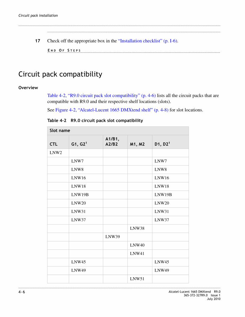
............................................................................................................................................................................................................................................................4-6 Alcatel-Lucent 1665 DMXtend R9.0
365-372-327R9.0 Issue 1July 2010
............................................................................................................................................................................................................................................................
Circuit pack installation
........................................................................................................................................................................................................................
17 Check off the appropriate box in the “Installation checklist” (p. I-6).
........................................................................................................................................................E N D O F S T E P S
Circuit pack compatibility
Overview
Table 4-2, “R9.0 circuit pack slot compatibility” (p. 4-6) lists all the circuit packs that are compatible with R9.0 and their respective shelf locations (slots).
See Figure 4-2, “Alcatel-Lucent 1665 DMXtend shelf” (p. 4-8) for slot locations.
Table 4-2 R9.0 circuit pack slot compatibility
Slot name
CTL G1, G21A1/B1, A2/B2 M1, M2 D1, D21
LNW2
LNW7 LNW7
LNW8 LNW8
LNW16 LNW16
LNW18 LNW18
LNW19B LNW19B
LNW20 LNW20
LNW31 LNW31
LNW37 LNW37
LNW38
LNW39
LNW40
LNW41
LNW45 LNW45
LNW49 LNW49
LNW51

............................................................................................................................................................................................................................................................Alcatel-Lucent 1665 DMXtend R9.0365-372-327R9.0 Issue 1July 2010
4-7
............................................................................................................................................................................................................................................................
Circuit pack installation
LNW52
LNW55 LNW55
LNW62 LNW62
LNW632 LNW632
LNW642 LNW642
LNW662 LNW662
LNW73/73C2 LNW73/73C2
LNW742 LNW742
LNW84 LNW84
LNW872 LNW872
LNW111
LNW112
LNW140 LNW140
LNW141 LNW141
LNW1702 LNW1702
LNW302
LNW380
LNW382
LNW391
LNW402 LNW402
LNW601
LNW7053
LNW785 LNW785
LNW801 LNW801
177D1 177D1
LNW434 LNW425
LNW964
Slot name
CTL G1, G21A1/B1, A2/B2 M1, M2 D1, D21

............................................................................................................................................................................................................................................................4-8 Alcatel-Lucent 1665 DMXtend R9.0
365-372-327R9.0 Issue 1July 2010
............................................................................................................................................................................................................................................................
Circuit pack installation
Figure 4-2 Alcatel-Lucent 1665 DMXtend shelf
LNW955
LNW986 LNW986
Notes:1 177D Apparatus Blanks are required in all unequipped function unit slots to provide
proper air flow for cooling.
2 This pack will only work in slot 1 unless the shelf is equipped with LNW141 or LNW84.
3 The LNW705 can onbly be installed in the G2 slot.
4 LNW43 Apparatus Blanks or LNW96 System Detectable Blanks are required in all unequipped A/B Slots to provide proper air flow for cooling.
5 LNW42 Apparatus Blanks or LNW95 System Detectable Blanks are required in all unequipped Main Slots to provide proper air flow for cooling.
6 System Detectable Blank Card for slots D and G. Apparatus Blanks are required in all unequipped function unit slots to provide proper air flow for cooling.
Slot name
CTL G1, G21A1/B1, A2/B2 M1, M2 D1, D21

............................................................................................................................................................................................................................................................Alcatel-Lucent 1665 DMXtend R9.0365-372-327R9.0 Issue 1July 2010
4-9
............................................................................................................................................................................................................................................................
Circuit pack installation
Initial circuit pack installation
Description
This section provides instructions for installing, but not fully seating, circuit packs into the Alcatel-Lucent 1665 DMXtend shelf. After circuit packs have been unpacked, they may be placed in their respective slots in the Alcatel-Lucent 1665 DMXtend shelf but not fully engaged in the backplane connector. The circuit packs will be fully installed (seated) in the next section.
Note: If office alarms are connected, it is advisable to disconnect the office alarm cable while performing the procedures in this section to prevent spurious alarms from being reported. Reconnect the office alarm cable after completion of all testing.
To protect against damage due to electrostatic discharge, a properly grounded ESD wrist strap must be worn when handling equipment.
LNW2 (SYSCTL) installation
Follow this procedure to install the LNW2 (SYSCTL) circuit pack into the Alcatel-Lucent 1665 DMXtend shelf.
........................................................................................................................................................................................................................
1 Remove the SYSCTL circuit pack from the packing material.
........................................................................................................................................................................................................................
2 Identify the CTL slot on the Alcatel-Lucent 1665 DMXtend shelf. See Figure 4-2, “Alcatel-Lucent 1665 DMXtend shelf” (p. 4-8).
........................................................................................................................................................................................................................
3 Place the SYSCTL circuit pack into the CTL slot on the Alcatel-Lucent 1665 DMXtend shelf. Do NOT engage the circuit pack in the backplane connector.
CAUTION177D or LNW98 Apparatus Blanks are required in all unequipped D and G function unit slots to provide proper air flow for cooling.
LNW42 or LNW95 Apparatus Blanks are required in all unequipped Main slots to provide proper air flow for cooling.
LNW43 or LNW96 Apparatus Blanks are required in all unequipped A/B slots to provide proper air flow for cooling.
CAUTION
ESD hazard
............................................................................................................................................................................................................................................................4-10 Alcatel-Lucent 1665 DMXtend R9.0
365-372-327R9.0 Issue 1July 2010
............................................................................................................................................................................................................................................................
Circuit pack installation
........................................................................................................................................................................................................................
4 Check off the appropriate box in the “Installation checklist” (p. I-6).
........................................................................................................................................................E N D O F S T E P S
OC-3/OC-12/OC-48/OC-192 main OLIU installation
Follow this procedure to install the following OC-3/OC-12/OC-48/OC-192 main OLIU circuit packs in the Alcatel-Lucent 1665 DMXtend shelf.
• LNW38 OC-12 IR
• LNW40 OC-3 IR
• LNW41 OC-48 PTM
• LNW51 OC-12 LR
• LNW84 OC-3/OC-12/OC-48 PTM
• LNW140 OC-3 IR
• LNW141 OC-192 PTM
• LNW302 OC-3 PTM
• LNW380 OC-12 LR
• LNW382 OC-12 PTM
• LNW601 OC-3 LR1
Note: The LNW140, LNW141 and LNW84 require the comcode 849031372 shelf that allows the center dividers to be removed. See Chapter 2, “Alcatel-Lucent 1665 DMXtend center divider” for details on how to remove them.
........................................................................................................................................................................................................................
1 Remove the first main OLIU circuit pack from the packing material.
........................................................................................................................................................................................................................
2 Identify the M1 slot on the Alcatel-Lucent 1665 DMXtend shelf. See Figure 4-2, “Alcatel-Lucent 1665 DMXtend shelf” (p. 4-8).
CAUTIONEquipment damage
The LNW38, LNW40, LNW51, LNW140, LNW380 and LNW601 OLIU circuit packs are equipped with optics that do not meet GR-78 R9-3 requirements on ESD susceptibility. Always use proper ESD procedures when handling these OLIU circuit packs to avoid equipment damage.

............................................................................................................................................................................................................................................................Alcatel-Lucent 1665 DMXtend R9.0365-372-327R9.0 Issue 1July 2010
4-11
............................................................................................................................................................................................................................................................
Circuit pack installation
........................................................................................................................................................................................................................
3 Place the main OLIU circuit pack into the M1 slot on the Alcatel-Lucent 1665 DMXtend shelf. Do NOT engage the circuit pack in the backplane connector.
........................................................................................................................................................................................................................
4 Remove the second main OLIU from the packing material.
........................................................................................................................................................................................................................
5 Identify the M2 slot on the Alcatel-Lucent 1665 DMXtend shelf. See Figure 4-2, “Alcatel-Lucent 1665 DMXtend shelf” (p. 4-8).
........................................................................................................................................................................................................................
6 Place the second main OLIU circuit pack into the M2 slot on the Alcatel-Lucent 1665 DMXtend shelf. Do NOT engage the circuit pack in the backplane connector.
Important! If any of the main slots are to remain unequipped, install a LNW42 or LNW95 apparatus blank to provide proper air flow for cooling. For LNW140, LNW141 or LNW84 main OLIUs the center divider must be removed and in the unused slot a LNW98 apparatus blanks installed to provide proper air flow for cooling.
........................................................................................................................................................................................................................
7 Check off the appropriate box in the “Installation checklist” (p. I-6).
........................................................................................................................................................E N D O F S T E P S
LNW7 (28DS1PM) and LNW8/LNW801 (56DS1E1) installation (optional)
Follow this procedure only if installing LNW7 (28DS1PM) or LNW8/LNW801 (56DS1E1) circuit packs into the Alcatel-Lucent 1665 DMXtend shelf.
Note: The LNW7 is not supported when the LNW141 or LNW84 VLF main OLIU is used.
........................................................................................................................................................................................................................
1 See the engineering job specification. Identify the proper function group slots that LNW7, LNW8, or LNW801 circuit pack will be installed into.
........................................................................................................................................................................................................................
2 Remove the LNW7, LNW8, or LNW801 from the packing material.

............................................................................................................................................................................................................................................................4-12 Alcatel-Lucent 1665 DMXtend R9.0
365-372-327R9.0 Issue 1July 2010
............................................................................................................................................................................................................................................................
Circuit pack installation
........................................................................................................................................................................................................................
3 Place the circuit pack into the shelf (slot D1 or G1 as required). Do NOT engage the circuit pack in the backplane connector.
........................................................................................................................................................................................................................
4 If a protection circuit pack is required, continue with Step 5 If not, install a 177D or LNW98 Apparatus Blank into the protection circuit pack slot (D2 or G2 as required), then proceed to Step 8.
Important! 177D or LNW98 Apparatus Blanks are required in all unused slots D and G to provide proper air flow for cooling.
........................................................................................................................................................................................................................
5 Remove the second LNW7, LNW8 or LNW801 from the packing material.
........................................................................................................................................................................................................................
6 Place the circuit pack into the shelf (slot D2, or G2 as required). Do NOT engage the circuit pack in the backplane connector.
........................................................................................................................................................................................................................
7 Repeat Step 1 through Step 6 for each additional function group D or G to be equipped with LNW7, LNW8 or LNW801 circuit packs.
........................................................................................................................................................................................................................
8 Check off the appropriate box in the “Installation checklist” (p. I-6).
........................................................................................................................................................E N D O F S T E P S
LNW16 (12DS3/EC1) and LNW19B (48DS3/EC1) installation (optional)
Follow this procedure only if installing LNW16 (12DS3/EC1) or LNW19B (48DS3/EC1) circuit packs into the Alcatel-Lucent 1665 DMXtend shelf.
........................................................................................................................................................................................................................
1 See the engineering job specification. Identify the proper function group(s) where LNW16 or LNW19B will be installed.
........................................................................................................................................................................................................................
2 Remove the LNW16 or LNW19B from the packing material.
............................................................................................................................................................................................................................................................Alcatel-Lucent 1665 DMXtend R9.0365-372-327R9.0 Issue 1July 2010
4-13
............................................................................................................................................................................................................................................................
Circuit pack installation
........................................................................................................................................................................................................................
3 Place the circuit pack into the shelf (slot D1 or G1 as required). Do NOT engage the circuit pack in the backplane connector.
........................................................................................................................................................................................................................
4 If a protection circuit pack is required, continue with the Step 5. If not, install a 177D or LNW98 Apparatus Blank into the protection circuit pack slot (D2 or G2 as required), then proceed to Step 7.
Important! 177D or LNW98 Apparatus Blanks are required in all unused slots D and G to provide proper air flow for cooling.
........................................................................................................................................................................................................................
5 Remove the second LNW16 or LNW19B from the packing material.
........................................................................................................................................................................................................................
6 Place the circuit pack into the shelf (slot D2 or G2 as required). Do NOT engage the circuit pack in the backplane connector.
........................................................................................................................................................................................................................
7 Repeat Step 1 through Step 6 for each additional function group to be equipped with LNW16 or LNW19B circuit packs.
........................................................................................................................................................................................................................
8 Check off the appropriate box in the “Installation checklist” (p. I-6).
........................................................................................................................................................E N D O F S T E P S
LNW18 (12TMUX) and LNW20 (48TMUXDS3EC1) installation (optional)
Follow this procedure only if installing LNW18 (12TMUX) or LNW20 (48TMUXDS3EC1) into the Alcatel-Lucent 1665 DMXtend shelf.
........................................................................................................................................................................................................................
1 See the engineering job specification. Identify the proper function group(s) where LNW18 or LNW20 will be installed.
........................................................................................................................................................................................................................
2 Remove the LNW18 or LNW20 from the packing material.

............................................................................................................................................................................................................................................................4-14 Alcatel-Lucent 1665 DMXtend R9.0
365-372-327R9.0 Issue 1July 2010
............................................................................................................................................................................................................................................................
Circuit pack installation
........................................................................................................................................................................................................................
3 Place the circuit pack into the shelf (slot D1 or G1 as required). Do NOT engage the circuit pack in the backplane connector.
........................................................................................................................................................................................................................
4 If a protection circuit pack is required, continue with the Step 5. If not, install a 177D or LNW98 Apparatus Blank into the protection circuit pack slot (D2 or G2 as required), then proceed to Step 7.
Important! 177D or LNW98 Apparatus Blanks are required in all unused slots D and G to provide proper air flow for cooling.
........................................................................................................................................................................................................................
5 Remove the second LNW18 or LNW20 from the packing material.
........................................................................................................................................................................................................................
6 Place the circuit pack into the shelf (slot D2 or G2 as required). Do NOT engage the circuit pack in the backplane connector.
........................................................................................................................................................................................................................
7 Repeat Step 1 through Step 6 for each additional function group to be equipped with LNW18 or LNW20 circuit pack.
........................................................................................................................................................................................................................
8 Check off the appropriate box in the Table I-2, “Installation checklist” (p. I-6).
........................................................................................................................................................E N D O F S T E P S
LNW31 (OC-48 OLIU) low-speed installation (optional)
Follow this procedure only if installing LNW31 (OC-48 OLIU) circuit packs into the Alcatel-Lucent 1665 DMXtend shelf.
........................................................................................................................................................................................................................
1 See the engineering job specification. Identify the proper function group(s) and/or growth slot(s) where LNW31 circuit pack will be installed.
........................................................................................................................................................................................................................
2 Remove the LNW31 from the packing material.
............................................................................................................................................................................................................................................................Alcatel-Lucent 1665 DMXtend R9.0365-372-327R9.0 Issue 1July 2010
4-15
............................................................................................................................................................................................................................................................
Circuit pack installation
........................................................................................................................................................................................................................
3 Place the circuit pack into the shelf (slot D1 or G1 as required). Do NOT engage the circuit pack in the backplane connector.
........................................................................................................................................................................................................................
4 If a companion circuit pack is required, continue with the Step 5. If not, install a 177D or LNW98 Apparatus Blank into the protection circuit pack slot (D2 or G2 as required), then proceed to Step 7.
Note: 177D or LNW98 Apparatus Blanks are required in all unused slots D and G to provide proper air flow for cooling.
........................................................................................................................................................................................................................
5 Remove the second LNW31 from the packing material.
........................................................................................................................................................................................................................
6 Place the circuit pack into the shelf (slot D2 or G2 as required).
........................................................................................................................................................................................................................
7 Repeat Step 1 through Step 6 for each additional function group and/or growth slot to be equipped with LNW31 circuit packs.
........................................................................................................................................................................................................................
8 Check off the appropriate box in the Table I-2, Installation checklist.
........................................................................................................................................................E N D O F S T E P S
LNW37 (OC-3 4 port PTM OLIU) or LNW45 (OC-3 8 port PTM OLIU)
Follow this procedure if installing the LNW37 (OC-3 4 port PTM OLIU) or LNW45 (OC-3 8 port PTM OLIU) circuit packs into the Alcatel-Lucent 1665 DMXtend shelf.
Note: The LNW37 or LNW45 circuit pack comes in separate boxes, with one box containing the circuit pack, and the other containing the ordered quantity of PTMs. This procedure will consist of two parts.
– Install the circuit card
– Install the PTM.
........................................................................................................................................................................................................................
1 See the engineering job specification. Identify the proper function group(s) and/or growth slot(s) where LNW37 or LNW45 circuit pack will be installed.
............................................................................................................................................................................................................................................................4-16 Alcatel-Lucent 1665 DMXtend R9.0
365-372-327R9.0 Issue 1July 2010
............................................................................................................................................................................................................................................................
Circuit pack installation
........................................................................................................................................................................................................................
2 Remove the LNW37 or LNW45 from the packing material.
........................................................................................................................................................................................................................
3 Place the circuit pack into the shelf (slot D1 or G1 as required). Do NOT engage the circuit pack in the backplane connector.
........................................................................................................................................................................................................................
4 If a companion circuit pack is required, continue with Step 5. If not, install a 177D or LNW98 Apparatus Blank into the protection circuit pack slot (D2 or G2 as required), then proceed to Step 7.
Important! 177D or LNW98 Apparatus Blanks are required in all unused slots D and G to provide proper air flow for cooling.
........................................................................................................................................................................................................................
5 Remove the second LNW37 or LNW45 from the packing material.
........................................................................................................................................................................................................................
6 Place the circuit pack into the shelf (slot D2 or G2 as required).
........................................................................................................................................................................................................................
7 Repeat Step 1 through Step 6 for each additional function group and/or growth slot to be equipped with LNW37 or LNW45 circuit packs.
........................................................................................................................................................................................................................
8 Check off the appropriate box in the Table I-2, Installation checklist.
........................................................................................................................................................E N D O F S T E P S
LNW39/LNW391 (DS1/DS3/16/3), LNW111 (3DS3) and LNW112 (16DS1) installation (optional)
Follow this procedure only if installing LNW39/LNW391 (DS1/DS3/16/3), LNW111 (3DS3) or LNW112 (16DS1) circuit packs into the Alcatel-Lucent 1665 DMXtend shelf.
Note: The LNW39, LNW391, LNW111 and LNW112 are not supported when the LNW140 main OLIU and LNW141 or LNW84 VLF main OLIU is used.
........................................................................................................................................................................................................................
1 See the engineering job specification. Identify the proper function group slots where LNW39, LNW391, LNW111 or LNW112 circuit pack will be installed.

............................................................................................................................................................................................................................................................Alcatel-Lucent 1665 DMXtend R9.0365-372-327R9.0 Issue 1July 2010
4-17
............................................................................................................................................................................................................................................................
Circuit pack installation
........................................................................................................................................................................................................................
2 Remove the LNW39, LNW391, LNW111 or LNW112 from the packing material.
........................................................................................................................................................................................................................
3 Place the circuit pack into the shelf (slot A1/B1). Do NOT engage the circuit pack in the backplane connector.
........................................................................................................................................................................................................................
4 If a protection circuit pack is required, continue with Step 5 If not, install an LNW43 or LNW96 Apparatus Blank into the protection circuit pack slot (A2/B2), then proceed to Step 7.
Important! LNW43 or LNW96 Apparatus Blanks are required in all unused slots A1/B1 and A2/B2 to provide proper air flow for cooling.
........................................................................................................................................................................................................................
5 Remove the second LNW39, LNW391, LNW111 or LNW112 from the packing material.
........................................................................................................................................................................................................................
6 Place the circuit pack into the shelf (slot A2/B2). Do NOT engage the circuit pack in the backplane connector.
........................................................................................................................................................................................................................
7 Check off the appropriate box in the Table I-2, Installation checklist.
........................................................................................................................................................E N D O F S T E P S
LNW49 (OC-12 4 port PTM OLIU) low-speed installation (optional)
Follow this procedure only if installing the LNW49 (OC-12 4 port PTM OLIU) circuit packs into the Alcatel-Lucent 1665 DMXtend shelf.
Note: The LNW49 (OC-12 4 port PTM OLIU) circuit pack comes in separate boxes, with one box containing the circuit pack, and the other containing the ordered quantity of PTMs. This procedure will consist of two parts.
– Install the circuit card
– Install the PTM.
........................................................................................................................................................................................................................
1 See the engineering job specification. Identify the proper function group(s) and/or growth slot(s) where LNW49 circuit pack will be installed.

............................................................................................................................................................................................................................................................4-18 Alcatel-Lucent 1665 DMXtend R9.0
365-372-327R9.0 Issue 1July 2010
............................................................................................................................................................................................................................................................
Circuit pack installation
........................................................................................................................................................................................................................
2 Remove the LNW49 from the packing material.
........................................................................................................................................................................................................................
3 Place the circuit pack into the shelf (slot D1 or G1 as required). Do NOT engage the circuit pack in the backplane connector.
........................................................................................................................................................................................................................
4 If a companion circuit pack is required, continue with the Step 5. If not, install a 177D or LNW98 Apparatus Blank into the protection circuit pack slot (D2 or G2 as required), then proceed to Step 7.
Note: 177D or LNW98 Apparatus Blanks are required in all unused slots D and G to provide proper air flow for cooling.
........................................................................................................................................................................................................................
5 Remove the second LNW49 from the packing material.
........................................................................................................................................................................................................................
6 Place the circuit pack into the shelf (slot D2 or G2 as required).
........................................................................................................................................................................................................................
7 Repeat Step 1 through Step 6 for each additional function group and/or growth slot to be equipped with LNW49 circuit packs.
........................................................................................................................................................................................................................
8 Check off the appropriate box in the Table I-2, Installation checklist.
........................................................................................................................................................E N D O F S T E P S
LNW62 (4 OC-48 PTM OLIU) or LNW55 (OC-3/OC-12/OC-48 12/4 port OLIU) low speed installation (optional)
Follow this procedure only if installing the LNW62 (4 OC-48 PTM OLIU) or LNW55 (OC-3/OC-12/OC-48 12/4 PTM OLIU) circuit packs into the Alcatel-Lucent 1665 DMXtend shelf.
Note: A deeper shelf cover (comcode 849064282) is required for shelves equipped with LNW55 OC3/OC12/OC48, LNW84 OC3/OC12/OC48, LNW705 XM10G/8, and/or LNW785 OMD, circuit packs. This shelf cover provides more space to prevent fibers from touching the front cover when the cover is closed.

............................................................................................................................................................................................................................................................Alcatel-Lucent 1665 DMXtend R9.0365-372-327R9.0 Issue 1July 2010
4-19
............................................................................................................................................................................................................................................................
Circuit pack installation
Note: The LNW62 and the LNW55 circuit packs require the LNW141 or LNW84 VLF main OLIU to be used.
Note: The LNW62 and LNW55 circuit pack comes in separate boxes, with one box containing the circuit pack, and the other containing the ordered quantity of PTMs. This procedure will consist of two parts.
– Install the circuit card
– Install the PTM.
........................................................................................................................................................................................................................
1 See the engineering job specification. Identify the proper function group(s) and/or growth slot(s) where LNW62 or LNW55 circuit pack will be installed.
........................................................................................................................................................................................................................
2 Remove the LNW62 or LNW55 from the packing material.
........................................................................................................................................................................................................................
3 Place the circuit pack into the shelf (slot D1 or G1 as required). Do NOT engage the circuit pack in the backplane connector.
........................................................................................................................................................................................................................
4 If a companion circuit pack is required, continue with the Step 5. If not, install a 177D or LNW98 Apparatus Blank into the protection circuit pack slot (D2 or G2 as required), then proceed to Step 7.
Note: 177D or LNW98 Apparatus Blanks are required in all unused slots D and G to provide proper air flow for cooling.
........................................................................................................................................................................................................................
5 Remove the second LNW62 or LNW55 from the packing material.
........................................................................................................................................................................................................................
6 Place the circuit pack into the shelf (slot D2 or G2 as required).
........................................................................................................................................................................................................................
7 Repeat Step 7 through Step 6 for each additional function group and/or growth slot to be equipped with LNW62 circuit packs.
........................................................................................................................................................................................................................
8 Check off the appropriate box in the Table I-2, Installation checklist.
........................................................................................................................................................E N D O F S T E P S
............................................................................................................................................................................................................................................................4-20 Alcatel-Lucent 1665 DMXtend R9.0
365-372-327R9.0 Issue 1July 2010
............................................................................................................................................................................................................................................................
Circuit pack installation
LNW63 (GBE PL) 4 port or LNW64 (GBE PL) 8-port installation (optional)
Follow this procedure only if installing LNW63 (GBE PL) 4 port or LNW64 (GBE PL) 8 port circuit packs into the Alcatel-Lucent 1665 DMXtend shelf.
Note: The LNW63 (GBE PL) 4 port or LNW64 (GBE PL) 8 port requires either a LX or SX PTM.
........................................................................................................................................................................................................................
1 See the engineering job specification. Identify the proper function group slot (D1 or G1) where the LNW63 or LNW64 circuit pack will be installed.
Note: LNW63 or LNW64 circuit pack can only be installed in slot 1 of any function group unless the LNW141 or LNW84 VLF main OLIU is used. See Alcatel-Lucent 1665 Data Multiplexer Extend (DMXtend) Applications and Planning Guide 365-372-324 for allowed combinations.
........................................................................................................................................................................................................................
2 Remove the LNW63 or LNW64 circuit pack from the packing material.
........................................................................................................................................................................................................................
3 Place the circuit pack into the shelf (slot D1 or G1 as required). Do NOT engage the circuit pack in the backplane connector.
........................................................................................................................................................................................................................
4 Install a 177D or LNW98 Apparatus Blank into the companion circuit pack slot (D2 or G2 as required).
Important! 177D or LNW98 Apparatus Blanks are required in all unused slots D and G to provide proper air flow for cooling.
........................................................................................................................................................................................................................
5 Repeat Step 1 through Step 4 for each additional function group to be equipped with LNW63 or LNW64 circuit packs.
........................................................................................................................................................................................................................
6 Check off the appropriate box in the Table I-2, Installation checklist.
........................................................................................................................................................E N D O F S T E P S
LNW73/73C (4-Fiber channel FICON/ESCON) installation (optional)
Follow this procedure only if installing LNW73 or LNW73C circuit packs into the Alcatel-Lucent 1665 DMXtend shelf.

............................................................................................................................................................................................................................................................Alcatel-Lucent 1665 DMXtend R9.0365-372-327R9.0 Issue 1July 2010
4-21
............................................................................................................................................................................................................................................................
Circuit pack installation
........................................................................................................................................................................................................................
1 See the engineering job specification. Identify the proper function group slot (D1 or G1) where the LNW73/73C circuit pack will be installed.
Note: LNW73/73C circuit pack can only be installed in slot 1 of any function group unless the LNW141 or LNW84 VLF main OLIU is used. See Alcatel-Lucent 1665 Data Multiplexer Extend (DMXtend) Applications and Planning Guide 365-372-324 for allowed combinations.
........................................................................................................................................................................................................................
2 Remove the LNW73/73C from the packing material.
........................................................................................................................................................................................................................
3 Place the circuit pack into the shelf (slot D1 or G1 as required). Do NOT engage the circuit pack in the backplane connector.
........................................................................................................................................................................................................................
4 Install a 177D or LNW98 Apparatus Blank into the companion circuit pack slot (D2 or G2 as required).
Important! 177D or LNW98 Apparatus Blanks are required in all unused slots D and G to provide proper air flow for cooling.
........................................................................................................................................................................................................................
5 Repeat Step 1 through Step 4 for each additional function group to be equipped with LNW73 or 73C circuit packs.
........................................................................................................................................................................................................................
6 Check off the appropriate box in the Table I-2, Installation checklist.
........................................................................................................................................................E N D O F S T E P S
LNW66 (10/100T), LNW74 (10/100-PL), LNW87 (FE/GBE PL) installation (optional)
Follow this procedure if installing LNW66 (10/100T), LNW74 (10/100-PL), or LNW87 (FE/GBE PL) circuit packs into the Alcatel-Lucent 1665 DMXtend shelf.
........................................................................................................................................................................................................................
1 See the engineering job specification. Identify the proper function group slot (D1 or G1) where the LNW66, LNW74, or LNW87 circuit pack will be installed.
............................................................................................................................................................................................................................................................4-22 Alcatel-Lucent 1665 DMXtend R9.0
365-372-327R9.0 Issue 1July 2010
............................................................................................................................................................................................................................................................
Circuit pack installation
Note: The LNW66, LNW74, or LNW87 circuit pack can only be installed in slot 1 of any function group. The LNW74 or LNW87 can be installed into any function slots (D1, D2, G1 or G2) if the LNW141 or LNW84 VLF main OLIU is used. See Alcatel-Lucent 1665 Data Multiplexer Extend (DMXtend) Applications and Planning Guide 365-372-324 for allowed combinations.
Note: The LNW74 has 4 100BASE-LX ports that require PTM optics in addition to 16 10/100BASE-TX ports that are cabled from the rear of the shelf.
Note: The LNW87 is a 8-port, PTM-based Private Line Fast Ethernet/Gigabit Ethernet pack. The ports can be populated with either, 4 optical, 8 electrical PTMs, or a mix of 4 electrical and 4 optical PTMs.
........................................................................................................................................................................................................................
2 Remove the pack from the packing material.
........................................................................................................................................................................................................................
3 Place the circuit pack into the shelf (slot D1 or G1 as required). Do NOT engage the circuit pack in the backplane connector.
........................................................................................................................................................................................................................
4 Install a 177D or LNW98 Apparatus Blank into the companion circuit pack slot (D2 or G2 as required).
Note: 177D or LNW98 Apparatus Blanks are required in all unused slots D and G to provide proper air flow for cooling.
........................................................................................................................................................................................................................
5 Repeat Step 1 through Step 4 for each additional function group (slot D1 or G1 as required) to be equipped with LNW66, LNW74, or LNW87 circuit packs.
........................................................................................................................................................................................................................
6 Check off the appropriate box in the “Installation checklist” (p. I-6).
........................................................................................................................................................E N D O F S T E P S
LNW170 (GigE/FE)
Follow this procedure only if installing LNW70/170 circuit packs into the Alcatel-Lucent 1665 DMXtend shelf.
Note: The LNW170 circuit packs support both electrical and optical PTMs for both gigE and FE. When inserting them into ports, provision the card appropriately.
............................................................................................................................................................................................................................................................Alcatel-Lucent 1665 DMXtend R9.0365-372-327R9.0 Issue 1July 2010
4-23
............................................................................................................................................................................................................................................................
Circuit pack installation
........................................................................................................................................................................................................................
1 See the engineering job specification. Identify the proper function group slot (D-G) where the LNW70 or LNW170 circuit pack will be installed.
........................................................................................................................................................................................................................
2 Remove the LNW170 from the packing material.
........................................................................................................................................................................................................................
3 Place the circuit pack into the shelf (slot D1 or G1 as required). Do NOT engage the circuit pack in the backplane connector.
........................................................................................................................................................................................................................
4 If slot 2 is empty, install a 177D or LNW98 Apparatus Blank into the companion circuit pack slot.
Important! 177D or LNW98 Apparatus Blanks are required in all unused slots D and G to provide proper air flow for cooling.
........................................................................................................................................................................................................................
5 Repeat Step 1 through Step 4 for each additional function group to be equipped with LNW170 circuit packs.
........................................................................................................................................................................................................................
6 Check off the appropriate box in the “Installation checklist” (p. I-6).
........................................................................................................................................................E N D O F S T E P S
LNW402 OC48 1310 nm, 1550 nm, or DWDM PTM Optics
Follow this procedure to install the LNW402 circuit packs in the Alcatel-Lucent 1665 DMXtend shelf. The high-speed LNW402 is a single-port OLIU that employs PTM pluggable optics to offer 1310 nm, 1550 nm, or DWDM optics with a 12 STS-1 VT fabric. The LNW402 circuit pack and three of the supported OC-48 PTMs are approved for OSP deployments.
........................................................................................................................................................................................................................
1 See the engineering job specification. Identify the proper function group slots where the LNW402 circuit packs will be installed.
........................................................................................................................................................................................................................
2 Remove the first LNW402 circuit pack from the packing material.

............................................................................................................................................................................................................................................................4-24 Alcatel-Lucent 1665 DMXtend R9.0
365-372-327R9.0 Issue 1July 2010
............................................................................................................................................................................................................................................................
Circuit pack installation
........................................................................................................................................................................................................................
3 Place the circuit pack into the shelf (slot D1 or G1 as required). Do NOT engage the circuit pack in the backplane connector.
........................................................................................................................................................................................................................
4 Repeat Step 2 and Step 3 if a second LNW402 is required in the companion function/growth slot. If not, install a 177D or LNW98 Apparatus Blank into the protection circuit pack slot (D2 or G2 as required).
Note: 177D or LNW98 Apparatus Blanks are required in all unused slots D and G to provide proper air flow for cooling.
........................................................................................................................................................................................................................
5 Repeat Step 2 through Step 4 if an additional function/growth group is to be equipped with an LNW402 circuit pack.
........................................................................................................................................................................................................................
6 Check off the appropriate box in the “Installation checklist” (p. I-6).
........................................................................................................................................................E N D O F S T E P S
LNW705 XM10G/8 muxponder pack
Follow this procedure to install a LNW705 circuit pack in an Alcatel-Lucent 1665 DMXtend. The LNW705 XM10G/8 circuit pack multiplexes/demultiplexes up to 8 ports onto a single 10G wavelength. The LNW705 XM10G/8 circuit pack provides transport for the following types of signals:OC-3/12/48, 1GE, FC, FICON and 2XFC
Note: A deeper shelf cover (comcode 849064282) is required for shelves equipped with LNW55 OC3/OC12/OC48, LNW84 OC3/OC12/OC48, LNW705 XM10G/8, and/or LNW785 OMD, circuit packs. This shelf cover provides more space to prevent fibers from touching the front cover when the cover is closed.
Note: The LNW705 circuit packs require PTM modules for the optical interface. This procedure will consist of two parts. Installing the circuit card and installing the PTM per Appendix E, “Pluggable transmission module installation”, Pluggable transmission modules (PTM) (p. E-1).
........................................................................................................................................................................................................................
1 See the engineering job specification. Identify the G2 slot where the LNW705 circuit pack will be installed.
............................................................................................................................................................................................................................................................Alcatel-Lucent 1665 DMXtend R9.0365-372-327R9.0 Issue 1July 2010
4-25
............................................................................................................................................................................................................................................................
Circuit pack installation
........................................................................................................................................................................................................................
2 Remove the LNW705 circuit pack from the packing material.
........................................................................................................................................................................................................................
3 Place the circuit pack into the shelf (slot G2). Do NOT engage the circuit pack in the backplane connector.
........................................................................................................................................................................................................................
4 See Appendix E, “Install pluggable modules” (p. B-8).
........................................................................................................................................................................................................................
5 Check off the appropriate box in “Installation checklist” (p. I-6).
........................................................................................................................................................E N D O F S T E P S
LNW785 OMD5/8 8-channel low-loss DWDM optical mux/demux
Follow this procedure to install the LNW785 circuit packs in the Alcatel-Lucent 1665 DMXtend shelf. The LNW785 OMD5/8 circuit pack multiplexes/demultiplexes up to 8 DWDM optical channels.
Note: A deeper shelf cover (comcode 849064282) is required for shelves equipped with LNW55 OC3/OC12/OC48, LNW84 OC3/OC12/OC48, LNW705 XM10G/8, and/or LNW785 OMD, circuit packs. This shelf cover provides more space to prevent fibers from touching the front cover when the cover is closed.
........................................................................................................................................................................................................................
1 See the engineering job specification. Identify the proper function group slots where the LNW785 circuit packs will be installed.
........................................................................................................................................................................................................................
2 Remove the first LNW785 circuit pack from the packing material.
........................................................................................................................................................................................................................
3 Place the circuit pack into the shelf (slot D1 or G1 as required). Do NOT engage the circuit pack in the backplane connector.
........................................................................................................................................................................................................................
4 Repeat Step 2 and Step 3 if a second LNW785 is required in the companion function/growth slot. If not, install a 177D or LNW98 Apparatus Blank into the protection circuit pack slot (D2 or G2 as required).
............................................................................................................................................................................................................................................................4-26 Alcatel-Lucent 1665 DMXtend R9.0
365-372-327R9.0 Issue 1July 2010
............................................................................................................................................................................................................................................................
Circuit pack installation
Note: 177D or LNW98 Apparatus Blanks are required in all unused slots D and G to provide proper air flow for cooling.
........................................................................................................................................................................................................................
5 Repeat Step 2 through Step 4 if an additional function/growth group is to be equipped with an LNW785 circuit pack.
........................................................................................................................................................................................................................
6 Check off the appropriate box in the “Installation checklist” (p. I-6).
........................................................................................................................................................E N D O F S T E P S
177D, LNW98 (Apparatus Blank) installation (optional)
Follow this procedure to install 177D or LNW98 Apparatus Blank(s) into the Alcatel-Lucent 1665 DMXtend shelf.
Note: 177D or LNW98 Apparatus Blanks are required in all unused slots D and G to provide proper air flow for cooling.
........................................................................................................................................................................................................................
1 Identify all the unequipped function unit (D or G) slots.
........................................................................................................................................................................................................................
2 Remove the 177D or LNW98 Apparatus Blank from the packing material.
........................................................................................................................................................................................................................
3 Place the 177D or LNW98 Apparatus Blank into an unequipped slots D and G on the shelf. Do NOT engage the blank pack in the backplane connector.
........................................................................................................................................................................................................................
4 Continue with the next unequipped D and G slot until all the unused slots are equipped with an 177D or LNW98 Apparatus Blank.
........................................................................................................................................................................................................................
5 Check off the appropriate box in the “Installation checklist” (p. I-6).
........................................................................................................................................................E N D O F S T E P S
LNW43, LNW96 (apparatus blank) installation (optional)
Follow this procedure to installs LNW43 or LNW96 Apparatus Blank(s) into the Alcatel-Lucent 1665 DMXtend shelf.

............................................................................................................................................................................................................................................................Alcatel-Lucent 1665 DMXtend R9.0365-372-327R9.0 Issue 1July 2010
4-27
............................................................................................................................................................................................................................................................
Circuit pack installation
Note: A LNW43 or LNW96 Apparatus Blank is required in any unequipped A1/B1 or A2/B2 slots to provide proper air flow for cooling.
........................................................................................................................................................................................................................
1 Identify any unequipped A1/B1 or A2/B2 slots.
........................................................................................................................................................................................................................
2 Remove the LNW43 or LNW96 Apparatus Blank from the packing material.
........................................................................................................................................................................................................................
3 Place the LNW43 or LNW96 Apparatus Blank into the unequipped A/B slot on the shelf. Do NOT engage the blank pack in the backplane connector.
........................................................................................................................................................................................................................
4 Continue with the next unequipped slot until all the unused A1/B1 or A2/B2 slots are equipped with an LNW43 or LNW96 Apparatus Blank.
........................................................................................................................................................................................................................
5 Check off the appropriate box in the “Installation checklist” (p. I-6).
........................................................................................................................................................E N D O F S T E P S
LNW42, LNW95 apparatus blank installation (optional)
Follow this procedure to install LNW42 or LNW95 Apparatus Blank(s) into the Alcatel-Lucent 1665 DMXtend shelf.
Note: A LNW42 or LNW95 Apparatus Blank is required in any unequipped Main slots to provide proper air flow for cooling.
........................................................................................................................................................................................................................
1 Identify any unequipped Main slots.
........................................................................................................................................................................................................................
2 Remove the LNW42 or LNW95 Apparatus Blank from the packing material.
........................................................................................................................................................................................................................
3 Place the LNW42 or LNW95 Apparatus Blank into the unequipped Main slot on the shelf. Do NOT engage the blank pack in the backplane connector.

............................................................................................................................................................................................................................................................4-28 Alcatel-Lucent 1665 DMXtend R9.0
365-372-327R9.0 Issue 1July 2010
............................................................................................................................................................................................................................................................
Circuit pack installation
........................................................................................................................................................................................................................
4 Check off the appropriate box in the “Installation checklist” (p. I-6).
........................................................................................................................................................E N D O F S T E P S

I I-1Alcatel-Lucent 1665 DMXtend R9.0365-372-327R9.0 Issue 1July 2010
............................................................................................................................................................................................................................................................
Part II: Stand-alone installation tests
Overview
Purpose
Part II covers Chapters 5 and 6. These sections cover the initial Graphical User Interface (GUI) or Craft Interface Terminal (CIT) software installation and turn-up testing on a new Alcatel-Lucent 1665 Data Multiplexer Extend (Alcatel-Lucent 1665 DMXtend) shelf. It is intended to verify correct electrical DS1/DS3/FE cable wiring to the DSX panel or punch down block as well SONET fiber routing to the LGX panel from the faceplates of installed packs.
Part II also provides the recommended checklist “Installation checklist” to follow when installing a Alcatel-Lucent 1665 DMXtend system. Use of the installation checklist is required to ensure a quality installation. All completed tasks should be checked off and those not completed should be duly noted as to the reason why. This checklist should be turned in as part of your job complete paperwork.
Contents
This part contains the following chapters:
Tools, test equipment and accessories
This section lists the tools, test equipment and accessories needed to perform all the procedures in this installation manual.
Stand-alone node setup Chapter 5
Stand-alone installation testing Chapter 6

............................................................................................................................................................................................................................................................I I -2 Alcatel-Lucent 1665 DMXtend R9.0
365-372-327R9.0 Issue 1July 2010
............................................................................................................................................................................................................................................................
Stand-alone installation tests
Listed below are the required tools, test equipment and accessories.
Qty. Description Comments
Screwdriver(s) A screwdriver(s) with the appropriate head(s) is (are) required for securing the mounting screws, repositioning the mounting brackets, installing the interfacing cables, and for setting the circuit breakers to the OFF position.
1 Thomas & Betts* R-5648B Crimping Tool
The crimping tool and wire stripper are only required if installing DS3 cables. The replacement cassette is for the wire stripper tool.
2 Paladin† Coaxial Wire Stripper R-5648B
Replacement Paladin† Cassette R-5648B D5
1 Wire-Wrap Gun
R-4496A
The wire-wrap gun is required for terminating DS1/E1 cable and must be able to accommodate 24 gauge wire.
1 ESD Wrist Strap
R-4987C
A wrist strap must be worn when handling circuit packs. Use the electrostatic discharge (ESD) jack provided on the shelf.
1 Ohmmeter
ITE-6379C
An ohmmeter is required to verify that the Alcatel-Lucent 1665 DMXtend is properly grounded.
1 DS1/E1 Error Rate Test Set
ITE-7113
A DS1/E1 error rate test set is required for testing of DS1/E1 cabling. A T-BERD 2209 or equivalent is recommended.
1 DS3 Error Rate Test Set
ITE-7113
A DS3 error rate test set is required for testing of DS3 cabling. A T-BERD 209 or equivalent is recommended.
1 Optical Test Set (Optional) A Optical test set is required for testing of low speed optics OC3/12/48. An Omniber 718 or equivalent is recommended.
2 or 3 LC-type Optical Fiber Jumper ITE-7169 (108918269)
Two optical fiber jumpers with LC type connectors are required to optically loop the Alcatel-Lucent 1665 DMXtend shelf for test purposes. In addition, for shelves containing optical circuit packs in any of the function unit slots, a single optical fiber jumper is required for testing of the individual ports.

............................................................................................................................................................................................................................................................Alcatel-Lucent 1665 DMXtend R9.0365-372-327R9.0 Issue 1July 2010
I I-3
............................................................................................................................................................................................................................................................
Stand-alone installation tests
1 15-dB LC-type LBO ITE-7196 (108279480)
LBOs are only required when optically looping the Alcatel-Lucent 1665 DMXtend shelves containing optical circuit packs in any of the function unit slots; a single 15-dB LBO is required for testing of the individual ports
Noyes OFS 300-200X Optical Fiber Scope
ITE-7129
This equipment may not be necessary at all locations. It is to be used when the ports need to be verified for cleanliness. If care is exercised when cleaning fibers, the optical fiber scope may not be needed
2.5mm Universal adapter cap ITE-7129 D1
For use with the Noyes OFS 300-200X Optical Fiber Scope
1.25mm Universal adapter cap ITE-7129 D2
Noyes VFS-1 ITE-7187 Video Fiber Scope1
This equipment may not be necessary at all locations. It is to be used when the ports need to be verified for cleanliness. If care is exercised when cleaning fibers, the video scope may not be needed
Individual presaturated alcohol wipes ITE-7136
99% pure isopropyl alcohol
1 CLETOP Cleaning Cassette ITE-7137
Type A Reel
1 CLETOP Cleaning Cassette Replacement Reel
ITE-7137 D1
Type A Reel
Luminex Stick port cleaners ITE-7134 & ITE-7135
1.25 mm and 2.5 mm sizes
Luminex Cloth R-6033 5.5” x 5.5”
Notes:* Registered trademark of Thomas & Betts Corporation
† Registered trademark of Paladin Corporation.
Qty. Description Comments
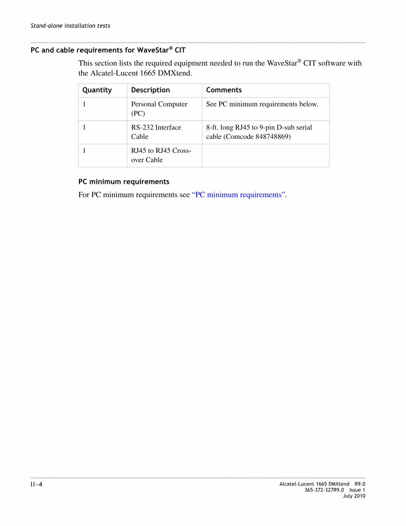
............................................................................................................................................................................................................................................................I I -4 Alcatel-Lucent 1665 DMXtend R9.0
365-372-327R9.0 Issue 1July 2010
............................................................................................................................................................................................................................................................
Stand-alone installation tests
PC and cable requirements for WaveStar® CIT
This section lists the required equipment needed to run the WaveStar® CIT software with the Alcatel-Lucent 1665 DMXtend.
PC minimum requirements
For PC minimum requirements see “PC minimum requirements”.
Quantity Description Comments
1 Personal Computer (PC)
See PC minimum requirements below.
1 RS-232 Interface Cable
8-ft. long RJ45 to 9-pin D-sub serial cable (Comcode 848748869)
1 RJ45 to RJ45 Cross-over Cable

............................................................................................................................................................................................................................................................Alcatel-Lucent 1665 DMXtend R9.0365-372-327R9.0 Issue 1July 2010
I I-5
............................................................................................................................................................................................................................................................
Stand-alone installation tests
Installation checklist
Section and chapter Procedure Required
Completed
Yes No
Part II: “Stand-alone installation tests”
Chapter 5, “Stand-alone node setup”
“Software installation” (p. 5-2) See Note 1
“Circuit pack installation” (p. 5-3) See Note 1
“Use of WaveStar® CIT software” (p. 5-6) Yes
“Steps” (p. 5-6) Yes
“Circuit pack program version verification” (p. 5-13)
Yes
“Alcatel-Lucent 1665 DMXtend shelf initialization” (p. 5-14)
Yes
Chapter 6, “Stand-alone installation testing”
“LBO software settings” (p. 6-4) See Note 1
“Clearing alarms” (p. 6-7) See Note 1
“Local equipment and cross-connect tests” (p. 6-8)
See Note 1
“DS1/E1 testing” (p. 6-9) See Note 1
“DS3/EC1 testing procedure” (p. 6-15) See Note 1
“LNW66 (10/100T), LNW74 (10/100), LNW87 (FE/GBE PL) TX Ethernet cabling testing” (p. 6-21)
See Note 1
“OC-3 low-speed testing” (p. 6-26) See Note 1
“OC-3 low-speed LNW37 PTM testing procedure” (p. 6-26)
See Note 1
“OC-3 low-speed LNW45 or LNW55 PTM testing procedure” (p. 6-28)
See Note 1
“OC-12 low-speed LNW49 and LNW55 PTM testing procedure” (p. 6-30)
See Note 1
“OC-12 low-speed LNW49 and LNW55 PTM testing procedure” (p. 6-30)
See Note 1
“OC-48 low-speed testing procedure” (p. 6-33) See Note 1

............................................................................................................................................................................................................................................................I I -6 Alcatel-Lucent 1665 DMXtend R9.0
365-372-327R9.0 Issue 1July 2010
............................................................................................................................................................................................................................................................
Stand-alone installation tests
“OC-48 PTM equipped low-speed testing procedure” (p. 6-35)
See Note 1
“LED test” (p. 6-37) Yes
“Office alarm test” (p. 6-38) See Note 1
“Automatic protection switching and alarm test” (p. 6-42)
See Note 1
“Manual switching tests” (p. 6-46) See Note 1
“External timing verification” (p. 6-49) See Note 1
“Miscellaneous (environmental) discrete telemetry test” (p. 6-52)
See Note 1
“Modem connection test” (p. 6-54) See Note 1
“Final operations” (p. 6-56) Yes
Notes: 1. Only required if equipped.
Section and chapter Procedure Required
Completed
Yes No

5-1Alcatel-Lucent 1665 DMXtend R9.0365-372-327R9.0 Issue 1July 2010
........................................................................................................................................................................
5 Stand-alone node setup
Overview
Purpose
The purpose of this chapter is to provide procedures for Graphical User Interface (GUI) or Craft Interface Terminal (CIT) software installation and circuit packs provided via work order. Also, the use of the Graphical User Interface (GUI) or Craft Interface Terminal (CIT).
Contents
This chapter provides information on the following topics
Tools, test equipment and accessories
Listed below are the required tools, test equipment and accessories.
Software installation 5-2
Circuit pack installation 5-3
Use of WaveStar® CIT software 5-6
Circuit pack program version verification 5-13
Alcatel-Lucent 1665 DMXtend shelf initialization 5-14
Quantity Description Comments
1 Personal Computer (PC) Required to run the WaveStar® CIT software.

........................................................................................................................................................................5-2 Alcatel-Lucent 1665 DMXtend R9.0
365-372-327R9.0 Issue 1July 2010
........................................................................................................................................................................
Stand-alone node setup
PC minimum requirements
For PC minimum requirements see “PC minimum requirements”.
Software installation
Description
Installation of the Alcatel-Lucent 1665 Data Multiplexer Extend (Alcatel-Lucent 1665 DMXtend) WaveStar® CIT software is covered in detail in the Alcatel-Lucent 1665 Data Multiplexer Extend (DMXtend) Release 9.0.0 Software Release Description, which is provided with the software CD. To install the CIT software, please follow the procedures in the “Installing software and documentation on a PC” section of the SRD.
Software installation
CIT software installation is accomplished by performing the “Installing software and documentation on a PC” section in the Alcatel-Lucent 1665 Data Multiplexer Extend (DMXtend) Release 9.0.0 Software Release Description which is shipped with the software CD. When the software installation is complete, Check off the appropriate box in the “Installation checklist” (p. II-5).
1 CIT Interface Cable 8-ft. long RJ45 to 9-pin D-sub serial cable (Comcode 848748869). Required to connect the PC to the CIT jack on the front of the SYSCTL circuit pack.
CIT Cross-Over Cable This cable is used for IAO LAN (OSI/TCP-IP) Front LAN connection cross over cable should be used if the shelf is directly connected to a PC and LAN 10BASE-T straight through cable should be used if shelf is connected to a hub
1 Software CD-ROM Verify latest software version is being used.
1 Software Release Description (SRD)
Verify latest the issue of the SRD is being used, for the software that is used.
LBOs 15-dB, 10-dB and 5-dB LBOs are required when looping back the main OLIUs on themselves.
Quantity Description Comments

........................................................................................................................................................................Alcatel-Lucent 1665 DMXtend R9.0365-372-327R9.0 Issue 1July 2010
5-3
........................................................................................................................................................................
Stand-alone node setup
Circuit pack installation
Description
This section provides instructions and the recommended order for installing (fully seating) the circuit packs in the Alcatel-Lucent 1665 DMXtend shelf. The procedures in this section assume that the SYSCTL is installed and operational.
Locations of circuit packs (function unit slots) are shown in Figure 4-2, “Alcatel-Lucent 1665 DMXtend shelf” (p. 4-8).
Circuit packs are keyed to prevent being inserted into the wrong shelf position. Installing circuit packs requires some force.
When a circuit pack is installed, its FAULT LED will light for several seconds then extinguish.
A properly grounded ESD wrist strap MUST be worn when handling circuit packs.
Note: The UPD/INIT pushbutton on the SYSCTL circuit pack is recessed and will require a pointed object.
CAUTIONWhen installing the circuit packs, be careful to insert them straight to avoid damaging the backplane pins.
CAUTION
ESD hazard
CAUTION
Laser Safety
When connecting fiber loops between the IN and OUT ports on optical circuit packs, always connect to the IN port first and then the OUT port. This will prevent any optical radiation from being present at the fiber end.For more detailed information and safety precautions, see Chapter 1, “Safety”.
........................................................................................................................................................................5-4 Alcatel-Lucent 1665 DMXtend R9.0
365-372-327R9.0 Issue 1July 2010
........................................................................................................................................................................
Stand-alone node setup
Steps
................................................................................................................................................
1 Fully insert one or both (if two are equipped) M1 and M2 OLIUs into the shelf.
Note: Using a gentle steady pressure on both ends of the circuit pack, slide the circuit pack into the slot until it is fully seated. Then close the faceplate latch and tighten the retainer screw on the other end.
Note: The LNW140, LNW141, and LNW84 require shelf comcode 849031372 with the center dividers removed. See Chapter 2, “Alcatel-Lucent 1665 DMXtend center divider” (p. 2-5) to remove the dividers
Note: A deeper shelf cover (comcode 849064282) is required for shelves equipped with LNW55 OC3/OC12/OC48, LNW84 OC3/OC12/OC48, LNW705 XM10G/8, and/or LNW785 OMD, circuit packs. This shelf cover provides more space to prevent fibers from touching the front cover when the cover is closed.
................................................................................................................................................
2 Fully seat LNW42 or LNW95 Apparatus Blanks in any unequipped Main slots. For LNW140, LNW141 or LNW84 main OLIUs the center divider must be removed and in the unused slot a LNW98 apparatus blanks installed to provide proper air flow for cooling.
Note: Using a gentle steady pressure on both ends of the circuit pack, slide the circuit pack into the slot until it is fully seated. Then close the faceplate latch and tighten the retainer screw on the other end.
................................................................................................................................................
3 If the LNW41 (OC-48), LNW141 (OC-192) or LNW84 (OC-3/OC-12/OC-48) mains are being used, insert the PTMs at this time. See Appendix B, “PTM modules” for proper insertion.
................................................................................................................................................
4 Connect IN to OUT on the OLIU in the M1 slot of the Alcatel-Lucent 1665 DMXtend shelf using an optical fiber jumper cable and a 15-dB LBO. See Appendix A, “Fiber cleaning” for proper fiber cleaning instructions.
CAUTION
Equipment damage
The LNW38, LNW40, LNW51, LNW140, LNW302, LNW380, LNW382, and LNW601 OLIU circuit packs are equipped with optics that do not meet GR-78 R9-3 requirements on ESD susceptibility. Always use proper ESD procedures when handling these OLIU circuit packs to avoid equipment damage.

........................................................................................................................................................................Alcatel-Lucent 1665 DMXtend R9.0365-372-327R9.0 Issue 1July 2010
5-5
........................................................................................................................................................................
Stand-alone node setup
Connect IN to OUT on the OLIU in the M2 slot of the Alcatel-Lucent 1665 DMXtend shelf using an optical fiber jumper cable and a 15-dB LBO.
Result: After a few minutes the flashing FAULT LEDs should extinguish on each OLIU circuit pack. If the shelf is externally timed the flashing FAULT LEDs may not extinguish until correct framing is selected. The FAULT, MJ and NE LEDs will light on the SYSCTL due to DCC alarms created by optically looping the OLIUs. These SYSCTL LEDs will remain lit until the DCC is disabled in the “Clearing alarms” (p. 6-7) section.
................................................................................................................................................
5 Starting with slot A1/B1, fully seat the circuit pack slotted there using a steady pressure on both of the faceplate latches (where applicable) at the same time until the circuit pack is fully seated.
Note: The ACTIVE and FAULT LEDs should light when circuit packs are inserted and the FAULT LED should extinguish after a short period of time.
Note: For slots A1/B1 and A2/B2 only; using a gentle steady pressure on both ends of the circuit pack, slide the circuit pack into the slot until it is fully seated. Then close the faceplate latch.
................................................................................................................................................
6 Continue seating circuit packs with slot A2/B2 and then on to G1, G2, D1, and D2.
Note: Some circuit packs such as the LNW63, LNW66, and LNW170 may take several minutes before their FAULT LEDs extinguish.
................................................................................................................................................
7 Fully seat 177D or LNW98 Apparatus Blanks in any other unfilled D and G slots.
................................................................................................................................................
8 Fully seat LNW43 or LNW96 Apparatus Blanks in any A/B unfilled slots.
Note: Using a gentle steady pressure on both ends of the circuit pack, slide the circuit pack into the slot until it is fully seated. Then close the faceplate latch.
CAUTION
Equipment damage
The LNW38, LNW40, LNW51, LNW140, LNW302, LNW380, LNW382, and LNW601 OLIU circuit packs are equipped with optics that do not meet GR-78 R9-3 requirements on ESD susceptibility. Always use proper ESD procedures when handling these OLIU circuit packs to avoid equipment damage.

........................................................................................................................................................................5-6 Alcatel-Lucent 1665 DMXtend R9.0
365-372-327R9.0 Issue 1July 2010
........................................................................................................................................................................
Stand-alone node setup
................................................................................................................................................
9 If there are any FAULT LEDs on or flashing on any of the inserted circuit packs; press the UPD/INIT pushbutton on the SYSCTL circuit pack.
Result: The operation of the UPD/INIT pushbutton on the SYSCTL circuit pack will update the system and should clear any flashing FAULT LEDs on any of the low speed circuit packs.
................................................................................................................................................
10 If FAULT LEDs remain lit on any of the inserted circuit packs, replace the respective circuit pack.
................................................................................................................................................
11 Any other alarms will be cleared later on in Chapter 6, “Stand-alone installation testing”, “Clearing alarms” (p. 6-7).
................................................................................................................................................
12 Check off the appropriate box in the “Installation checklist” (p. II-5).
........................................................................................................................................................E N D O F S T E P S
Use of WaveStar® CIT software
Description
Complete the following steps to login to the Alcatel-Lucent 1665 DMXtend via WaveStar® CIT. It is assumed that the CIT software has been installed on the PC and the LNW2 system controller is installed and operational to the Alcatel-Lucent 1665 DMXtend shelf per the Software Release Description.
Steps
................................................................................................................................................
1 Connect the PC serial port to the RS-232 port of the SYSCTL circuit pack with a serial RS-232 cable [Table 3-23, “CIT Cable Assembly” (p. 3-69)]. Or connect the PC LAN port to the front LAN port of the SYSCTL circuit pack with a RJ45 to RJ45 cross-over cable Table 3-14, “LAN 10Base-T straight-through cable connections” (p. 3-47).
Note: An IP address must be assigned to the NIC card on the PC or laptop. Otherwise, you may experience login problems. To assign an IP address, start the DOS prompt on the computer, and type the command ipconfig/all. The command will show

........................................................................................................................................................................Alcatel-Lucent 1665 DMXtend R9.0365-372-327R9.0 Issue 1July 2010
5-7
........................................................................................................................................................................
Stand-alone node setup
an IP address line. If there is no address line or 0.0.0.0 for an IP address, then you must assign an IP address to the NIC card of the computer.
................................................................................................................................................
2 Start the WaveStar® CIT software on the PC by double clicking on the WaveStar® icon that was created by the installation procedure.
The following windows appear:

........................................................................................................................................................................5-8 Alcatel-Lucent 1665 DMXtend R9.0
365-372-327R9.0 Issue 1July 2010
........................................................................................................................................................................
Stand-alone node setup
................................................................................................................................................
3 If necesssary, enter the following in the Login window: Note: User ID and password are case sensitive.
User ID: LUC01Password: LUC+01
Note: When the CIT is installed, there is an optional step to enable or disable CIT logins. This screen shot would not be displayed if the user chose to disable CIT logins.

........................................................................................................................................................................Alcatel-Lucent 1665 DMXtend R9.0365-372-327R9.0 Issue 1July 2010
5-9
........................................................................................................................................................................
Stand-alone node setup
................................................................................................................................................
4 Click OK to connect. The screen appears:

........................................................................................................................................................................5-10 Alcatel-Lucent 1665 DMXtend R9.0
365-372-327R9.0 Issue 1July 2010
........................................................................................................................................................................
Stand-alone node setup
................................................................................................................................................
5 After reading the Legal Notice, click OK and the following window appears.
................................................................................................................................................
6 Under NE Name, enter LT-DMXTEND.
................................................................................................................................................
7 Under NE Type, select DMXtend from the drop-down list.
................................................................................................................................................
8 Under Connection Type, click on the drop-down menu arrow and choose Serial, OSI, or TCP/IP depending on the type of connection you are using.
Note: TCP/IP is available when the SYSCTL has a bootcode of 5.1 or higher. The SYSCTL (LNW2) displays the boot code on initial turn up and the 5.1 bootcode is indicated by a flashing M P 5 1 in the display. When the bootcode is 5.1 or higher, the SYSCTL has a default IP address of 169.254.1.1. If the PC’s LAN card to is configured as DHCP, the SYSCTL will provide the PC with an IP address within a minute or so. Connection through TCP/IP is now possible using the default IP address of 169.254.1.1.

........................................................................................................................................................................Alcatel-Lucent 1665 DMXtend R9.0365-372-327R9.0 Issue 1July 2010
5-11
........................................................................................................................................................................
Stand-alone node setup
................................................................................................................................................
9 Click Graphical and the NE login screen appears.
................................................................................................................................................
10 Enter the Login information (case sensitive)for the shelf:User ID: LUC01Password: DMXTND2.5GClick OK and the NE legal notice appears.

........................................................................................................................................................................5-12 Alcatel-Lucent 1665 DMXtend R9.0
365-372-327R9.0 Issue 1July 2010
........................................................................................................................................................................
Stand-alone node setup
................................................................................................................................................
11 Click OK and the System View appears.
................................................................................................................................................
12 Familiarize yourself with different aspects of the Graphical presentation of a shelf including tool bars and menu bars.
................................................................................................................................................
13 Check off the appropriate box in the “Installation checklist” (p. II-5).
........................................................................................................................................................E N D O F S T E P S
........................................................................................................................................................................Alcatel-Lucent 1665 DMXtend R9.0365-372-327R9.0 Issue 1July 2010
5-13
........................................................................................................................................................................
Stand-alone node setup
Circuit pack program version verification
Description
This section provides instructions verifying that program versions on the circuit packs in the Alcatel-Lucent 1665 DMXtend shelf. The procedures in this section assume that the SYSCTL is installed and the circuit packs have been installed in the shelf as described in the preceding sections.
Steps
................................................................................................................................................
1 Log on to the Alcatel-Lucent 1665 DMXtend shelf using the CIT software as described in the “Use of WaveStar® CIT software” (p. 5-6).
................................................................................................................................................
2 In the System View, select View > Equipment.
Result: All packs inserted into the shelf are displayed.
................................................................................................................................................
3 Click on an installed circuit pack.
................................................................................................................................................
4 Click Select to issue the command.
Result: The circuit pack information is displayed. If the circuit pack has a program associated with it, the version number will be displayed next to Program Version:. Compare it to the table of Program Versions in Chapter 6 of the Alcatel-Lucent 1665 Data Multiplexer Extend (DMXtend) Release 9.0.0 Software Release Description.
................................................................................................................................................
5 Compare the Program Version to the information provided in the Alcatel-Lucent 1665 Data Multiplexer Extend (DMXtend) Release 9.0.0 Software Release Description.
Note: OLIU circuit packs are not considered “smart packs”, therefore will not provide program version. The exception is the VLF Mains.
................................................................................................................................................
6 If the Program Version did not match the version number in the Firmware Version table in the SRD, reseat that circuit pack and wait 15 minutes, and repeat this procedure from Step 2.

........................................................................................................................................................................5-14 Alcatel-Lucent 1665 DMXtend R9.0
365-372-327R9.0 Issue 1July 2010
........................................................................................................................................................................
Stand-alone node setup
................................................................................................................................................
7 Check off the appropriate box in the “Installation checklist” (p. II-5).
........................................................................................................................................................E N D O F S T E P S
Alcatel-Lucent 1665 DMXtend shelf initialization
Description
This section provides instructions for initializing the Alcatel-Lucent 1665 DMXtend shelf, to ensure that all circuit pack databases are correct for the current shelf and software release. The procedures in this section assume that the SYSCTL is installed and the circuit packs have all been installed in the shelf as described in the preceding sections.
Steps
................................................................................................................................................
1 Log on to the Alcatel-Lucent 1665 DMXtend shelf using the CIT software as described in the “Use of WaveStar® CIT software” (p. 5-6).
................................................................................................................................................
2 From the System View, select Fault > Reset > Initialize System.
Result: Click OK.
................................................................................................................................................
3 Click Yes to the Warning Message.
Result: The shelf resets and closes the CIT session.
................................................................................................................................................
4 Check off the appropriate box in the “Installation checklist” (p. II-5).
........................................................................................................................................................E N D O F S T E P S

6-1Alcatel-Lucent 1665 DMXtend R9.0365-372-327R9.0 Issue 1July 2010
............................................................................................................................................................................................................................................................
6 Stand-alone installation testing
Overview
Purpose
The purpose of this section is to verify proper transmission cabling installation and R9.0 functionality as well as the associated functionality of the Alcatel-Lucent 1665 Data Multiplexer Extend (Alcatel-Lucent 1665 DMXtend) shelf.
For end-to-end turn-up and testing procedures, see Alcatel-Lucent 1665 Data Multiplexer Extend (DMXtend) User Operations Guide 365-372-325.
Contents
This chapter provides information on the following topics:
LBO software settings 6-4
Clearing alarms 6-7
Local equipment and cross-connect tests 6-8
DS1/E1 testing 6-9
DS3/EC1 testing 6-15
LNW66, LNW74, and LNW87 testing 6-21
OC-3 low-speed testing 6-26
OC-12 low-speed testing 6-30
OC-48 low-speed testing 6-33
LED test 6-37
Office alarm test 6-38
Automatic protection switching and alarm test 6-42
Manual switching tests 6-46

............................................................................................................................................................................................................................................................6-2 Alcatel-Lucent 1665 DMXtend R9.0
365-372-327R9.0 Issue 1July 2010
............................................................................................................................................................................................................................................................
Stand-alone installation testing
External timing verification 6-49
Miscellaneous (environmental) discrete telemetry test 6-52
Modem connection test 6-54
Final operations 6-56

............................................................................................................................................................................................................................................................Alcatel-Lucent 1665 DMXtend R9.0365-372-327R9.0 Issue 1July 2010
6-3
............................................................................................................................................................................................................................................................
Stand-alone installation testing
Tools, test equipment and accessories
Listed below are the required tools, test equipment and accessories. For complete listing, see Part I or Part II:
Quantity Description Comments
Screwdriver(s) A screwdriver(s) with the appropriate head(s) is (are) required for securing the mounting screws, repositioning the mounting brackets, installing the interfacing cables, and for setting the circuit breakers to the OFF position.
1 ESD Wrist Strap A wrist strap must be worn when handling circuit packs. Use the electrostatic discharge (ESD) jack provided on the shelf.
1 DS1/E1 Error Rate Test Set
A DS1/E1 error rate test set is required for testing of DS1/E1 cabling. A T-BERD 2209 or equivalent is recommended.
1 DS3 Error Rate Test Set
A DS3 error rate test set is required for testing of DS3/EC1 cabling. A T-BERD 2209 or equivalent is recommended.
2 or 3 LC-type Optical Fiber Jumper (108918269)
Two optical fiber jumpers with LC-type connectors are required to optically loop the Alcatel-Lucent 1665 DMXtend shelf for test purposes. In addition, for shelves containing optical circuit packs in any of the function unit slots, a single optical fiber jumper is required for testing of the individual ports.
1 15 dB LC-type LBO (108279480)
For shelves containing optical circuit packs in any of the function unit slots (supported starting in release R1.1), a single 15-dB LBO is required for testing of the individual ports
1 Personal Computer (PC)
Required to run the WaveStar® CIT software.
1 CIT (RS-232) Interface Cable
8-ft. long RJ45 to 9-pin D-sub serial cable (Comcode 848748869). Required to connect the PC to the CIT jack on the front of the SYSCTL circuit pack.
2 LAN 10BaseT Straight-through Cable CAT 5 or better
As required to reach from front of Alcatel-Lucent 1665 DMXtend to the RJ45 patch panel

............................................................................................................................................................................................................................................................6-4 Alcatel-Lucent 1665 DMXtend R9.0
365-372-327R9.0 Issue 1July 2010
............................................................................................................................................................................................................................................................
Stand-alone installation testing
PC minimum requirements
For PC minimum requirements see “PC minimum requirements”.
LBO software settings
Description
This section provides instructions for setting the software Line Build Out (LBO) for the DS1/E1 and DS3/EC1 cabling. The SYSCTL, DS1/E1 and/or DS3/EC1 circuit packs must be installed and software must be loaded.
Follow this procedure to set the LBOs for the DS1/E1, DS1/DS3/16/3, DS3/EC1, and TMUX circuit packs.
Quantity Description Comments
1 Personal Computer (PC) Required to run the WaveStar® CIT software.
1 CIT Interface Cable 8-ft. long RJ45 to 9-pin D-sub serial cable (Comcode 848748869). Required to connect the PC to the CIT jack on the front of the SYSCTL circuit pack.
CIT Cross-Over Cable This cable is used for IAO LAN (OSI/TCP-IP) Front LAN connection cross over cable should be used if the shelf is directly connected to a PC and LAN 10BASE-T straight through cable should be used if shelf is connected to a hub
1 Software CD-ROM Verify latest software version is being used.
1 Software Release Description (SRD)
Verify latest the issue of the SRD is being used, for the software that is used.
LBOs 15-dB, 10-dB and 5-dB LBOs are required when looping back the main OLIUs on themselves.

............................................................................................................................................................................................................................................................Alcatel-Lucent 1665 DMXtend R9.0365-372-327R9.0 Issue 1July 2010
6-5
............................................................................................................................................................................................................................................................
Stand-alone installation testing
Setting DS1/E1 LBOs
........................................................................................................................................................................................................................
1 Log on to the Alcatel-Lucent 1665 DMXtend shelf using the CIT software as described in the “Use of WaveStar® CIT software” (p. 5-6).
........................................................................................................................................................................................................................
2 See the following table of cable lengths and LBO values. Determine the LBO value corresponding to the DS1/E1 cables installed.
........................................................................................................................................................................................................................
3 Use the GUI window click on Configuration:Equipment command.
........................................................................................................................................................................................................................
4 Double-click on a Function Group where the LNW7/LNW8/LNW112/LNW39/LNW140/LNW391/LNW801/LNW84 is located.
........................................................................................................................................................................................................................
5 Select VT Group1 and the first DS1/E1 in that group.
Result: A provisioning page will be displayed.
........................................................................................................................................................................................................................
6 Select Line Build Out 20 (0,133) from the drop-down window.
........................................................................................................................................................................................................................
7 Select Apply to: All Ports, This Pack
........................................................................................................................................................................................................................
8 Click Apply to issue the command.
Result: All DS1/E1 ports will have a LBO value of 20 for this pack.
LBO value
Distance (feet)
Cable type 1161A
20 0 - 133 (default)
40 133 - 267
60 267 - 420
80 420 - 550
100 550 - 655

............................................................................................................................................................................................................................................................6-6 Alcatel-Lucent 1665 DMXtend R9.0
365-372-327R9.0 Issue 1July 2010
............................................................................................................................................................................................................................................................
Stand-alone installation testing
Setting DS3/EC1 LBOs
The DS3/EC1 cabling will be tested with all ports provisioned for DS3. Set DS3 LBO values as follows.
........................................................................................................................................................................................................................
9 See the following table of cable lengths and LBO values. Determine the LBO value corresponding to the DS3 cables installed:
........................................................................................................................................................................................................................
10 Use the GUI window click on Configuration:Equipment command.
........................................................................................................................................................................................................................
11 Double-click on a Function Group where the LNW16/LNW18/LNW19B/LNW20 or LNW39/LNW111/LNW391/LNW84 is located.
........................................................................................................................................................................................................................
12 Select Port 1 and the first DS3 in that group.
Result: A provisioning page will be displayed.
........................................................................................................................................................................................................................
13 Select Line Build Out = In from the drop down window.
........................................................................................................................................................................................................................
14 Select Apply to: All Ports, This Pack
........................................................................................................................................................................................................................
15 Click Apply to issue the command.
Result: All DS3 ports will have a LBO value of In for this pack.
........................................................................................................................................................................................................................
16 Check off the appropriate box in the “Installation checklist” (p. II-5).
........................................................................................................................................................E N D O F S T E P S
LBO Value
Distance (Feet)
Cable Type 735A and 734D
IN 0 - 65 (default)
OUT > 65

............................................................................................................................................................................................................................................................Alcatel-Lucent 1665 DMXtend R9.0365-372-327R9.0 Issue 1July 2010
6-7
............................................................................................................................................................................................................................................................
Stand-alone installation testing
Clearing alarms
Description
In order to clear standing alarms the Alcatel-Lucent 1665 DMXtend synchronization will be optioned for “Free Running.” The DCC will be disabled in order to prevent DCC alarms from being generated due to the optical loopback on the main OLIUs.
........................................................................................................................................................................................................................
1 Use t the GUI to change the system timing. Configuration > Timing Sync
........................................................................................................................................................................................................................
2 The Configure Timing/Sync window will be displayed.
........................................................................................................................................................................................................................
3 Under the System Timing tab set the Timing Mode: to Free Running.
........................................................................................................................................................................................................................
4 Click OK to issue the command.
........................................................................................................................................................................................................................
5 Use the GUI to turn off the DCCs. Configuration > DCC Terminations
........................................................................................................................................................................................................................
6 The Configure DCC Terminations window will be displayed.
........................................................................................................................................................................................................................
7 For Port AID: select dcc-m1-1.
........................................................................................................................................................................................................................
8 For OSI Over DCC select disabled.
........................................................................................................................................................................................................................
9 Click Apply to send the command.
........................................................................................................................................................................................................................
10 For Port AID: select dcc-m2-1.
........................................................................................................................................................................................................................
11 For OSI Over DCC select disabled.

............................................................................................................................................................................................................................................................6-8 Alcatel-Lucent 1665 DMXtend R9.0
365-372-327R9.0 Issue 1July 2010
............................................................................................................................................................................................................................................................
Stand-alone installation testing
........................................................................................................................................................................................................................
12 Click Apply to send the command.
........................................................................................................................................................................................................................
13 If there are any FAULT LEDs on or flashing, press the UPD/INIT pushbutton on the SYSCTL circuit pack.
Note: LNW16/LNW19B (DS3/EC1), LNW18/LNW20 (48TMUXDS3EC1), LNW111 (3DS3) and LNW39/LNW391/LNW84 (DS1/DS3/16/3) circuit packs require a 75-ohm termination at the DSX-3 on all ports.
........................................................................................................................................................................................................................
14 If there are still FAULT LEDs on, replace the respective circuit pack.
........................................................................................................................................................................................................................
15 Leave the office alarm cable disconnected until all procedures and testing have been completed.
........................................................................................................................................................................................................................
16 Check off the appropriate box in the “Installation checklist” (p. II-5).
........................................................................................................................................................E N D O F S T E P S
Local equipment and cross-connect tests
Description
The tests in this section verify the proper operation of the circuit packs and the circuit pack positions in the Alcatel-Lucent 1665 DMXtend shelf. It verifies proper cabling from the Alcatel-Lucent 1665 DMXtend to the DSX cross-connect panel or connecting equipment. The shelf must successfully pass this test before testing any other feature of the Alcatel-Lucent 1665 DMXtend.
It is assumed that Chapter 4, “Circuit pack installation” is complete and the Alcatel-Lucent 1665 DMXtend shelf has fiber loopback cables on the Main OLIUs, with Far-End Communication disabled and synchronization set to free-running.
On initial installation/turn-up of Alcatel-Lucent 1665 DMXtend, there are no default cross-connects. All cross-connects need to be entered for these tests. Upon completion of this test, all cross-connections will be deleted.

............................................................................................................................................................................................................................................................Alcatel-Lucent 1665 DMXtend R9.0365-372-327R9.0 Issue 1July 2010
6-9
............................................................................................................................................................................................................................................................
Stand-alone installation testing
Note: If the shelf is not fully equipped, move circuit packs around and repeat the test. Test all circuit pack positions which have DSX cabling.
Note: After completing this test, isolate and correct any incorrect wiring or isolate and replace any failed units. If any cabling is corrected or units replaced, repeat the Local Equipment and cross-connect tests until the units pass without failures.
A properly grounded ESD wrist strap MUST be worn when handling circuit packs.
Unterminated optical connectors may emit laser radiation. Do not view beam with optical instruments.
DS1/E1 testing
DS1/E1 testing procedure
Perform the following steps for all Alcatel-Lucent 1665 DMXtend shelf function unit slots that are cabled to a DSX-1.
Function unit slot A/B must be cabled to the DSX-1 and must contain a DS1/DS3/16/3 (LNW39/LNW391/LNW84), 16/DS1 (LNW112) or OC-3/16DS1 (LNW40) circuit pack in order to perform these tests on the DS1/E1 portion of the cabling. function unit slot D or G must be cabled to the DSX-1 and must contain either a 28DS1 (LNW7) or 56DS1E1 (LNW8/LNW801) circuit pack in order to perform these tests. If the shelf is not fully populated, it may be necessary to move the circuit pack(s) from slot to slot in order to test all DS-1 cabling.
Note: The LNW39/LNW391/LNW84 (DS1/DS3/16/3), LNW112 (16DS1) or the OC-3/16DS1 (LNW140) circuit packs only support the first 16 DS1’s of the A function group.
This procedure requires the use of a DS1/E1 test set.
........................................................................................................................................................................................................................
1 Set the DS1/E1 test set to transmit and receive a Quasi-Random Sequence Signal (QRSS) with B8ZS formatting.
CAUTION
ESD hazard
WARNING
Laser hazard

............................................................................................................................................................................................................................................................6-10 Alcatel-Lucent 1665 DMXtend R9.0
365-372-327R9.0 Issue 1July 2010
............................................................................................................................................................................................................................................................
Stand-alone installation testing
........................................................................................................................................................................................................................
2 Connect a cable from the DS-1 test set transmit connection to the IN jack of the DSX-1 associated with the DS-1 tributary to be tested (start with the first).
........................................................................................................................................................................................................................
3 Connect a cable from the DS-1 test set receive connection to the OUT jack of the DSX-1 associated with the DS-1 tributary to be tested (start with the first).
Result: The DS-1 test set should indicate a blue (AIS) signal is being received.
........................................................................................................................................................................................................................
4 Use the GUI command to enter cross-connects.
........................................................................................................................................................................................................................
5 Click Configuration: Cross-Connections.
........................................................................................................................................................................................................................
6 Select Create a new cross-connection.
........................................................................................................................................................................................................................
7 Select Next.
........................................................................................................................................................................................................................
8 Select Rate= VT1.5: Type of Cross-connect= UPSR Add/Drop.
........................................................................................................................................................................................................................
9 Select Next.
........................................................................................................................................................................................................................
10 Select Range= Single VT.
........................................................................................................................................................................................................................
11 Select m1-1-1-1-1 to a1-1-1-1 (if using a combo card) or [d,g] if using the function slots.
........................................................................................................................................................................................................................
12 Click Finish to issue the command.
Result: The DS-1 test set should indicate it is receiving an error free QRSS signal with B8ZS formatting.
If an error-free signal is not received:
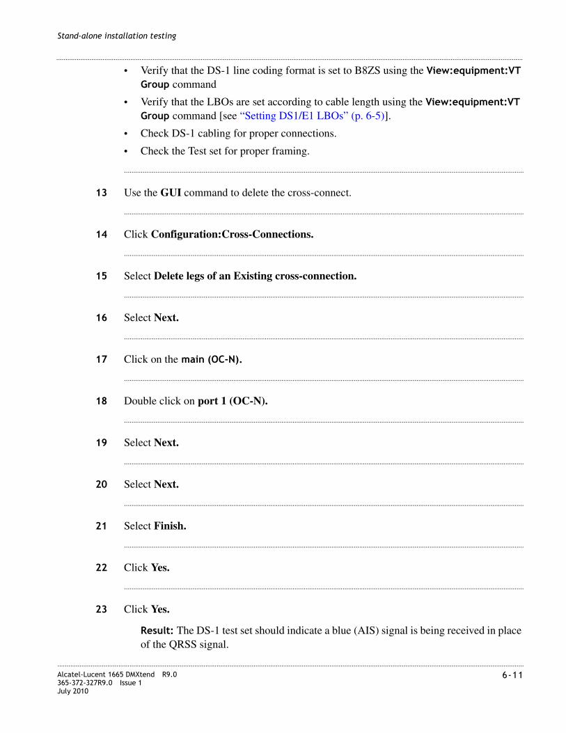
............................................................................................................................................................................................................................................................Alcatel-Lucent 1665 DMXtend R9.0365-372-327R9.0 Issue 1July 2010
6-11
............................................................................................................................................................................................................................................................
Stand-alone installation testing
• Verify that the DS-1 line coding format is set to B8ZS using the View:equipment:VT Group command
• Verify that the LBOs are set according to cable length using the View:equipment:VT Group command [see “Setting DS1/E1 LBOs” (p. 6-5)].
• Check DS-1 cabling for proper connections.
• Check the Test set for proper framing.
........................................................................................................................................................................................................................
13 Use the GUI command to delete the cross-connect.
........................................................................................................................................................................................................................
14 Click Configuration:Cross-Connections.
........................................................................................................................................................................................................................
15 Select Delete legs of an Existing cross-connection.
........................................................................................................................................................................................................................
16 Select Next.
........................................................................................................................................................................................................................
17 Click on the main (OC-N).
........................................................................................................................................................................................................................
18 Double click on port 1 (OC-N).
........................................................................................................................................................................................................................
19 Select Next.
........................................................................................................................................................................................................................
20 Select Next.
........................................................................................................................................................................................................................
21 Select Finish.
........................................................................................................................................................................................................................
22 Click Yes.
........................................................................................................................................................................................................................
23 Click Yes.
Result: The DS-1 test set should indicate a blue (AIS) signal is being received in place of the QRSS signal.

............................................................................................................................................................................................................................................................6-12 Alcatel-Lucent 1665 DMXtend R9.0
365-372-327R9.0 Issue 1July 2010
............................................................................................................................................................................................................................................................
Stand-alone installation testing
........................................................................................................................................................................................................................
24 Remove the test set connections from the DSX-1.
........................................................................................................................................................................................................................
25 Use the e GUI to send an upd-sys command.
........................................................................................................................................................................................................................
26 Click on Configuration > Update System > Update All.
........................................................................................................................................................................................................................
27 Click Yes to issue the command.
Result: This command will remove alarms generated by removing the test signals from the DSX-1.
........................................................................................................................................................................................................................
28 Repeat Step 2 through Step 27 to test each of the remaining DS-1 tributaries of the function unit, substituting the following address information.
Tributary @ DSX-1 Cross-connect
2 m1-1-1-1-2,a1-1-1-2
3 m1-1-1-1-3,a1-1-1-3
4 m1-1-1-1-4,a1-1-1-4
5 m1-1-1-2-1,a1-1-2-1
6 m1-1-1-2-2,a1-1-2-2
7 m1-1-1-2-3,a1-1-2-3
8 m1-1-1-2-4,a1-1-2-4
9 m1-1-1-3-1,a1-1-3-1
10 m1-1-1-3-2,a1-1-3-2
11 m1-1-1-3-3,a1-1-3-3
12 m1-1-1-3-4,a1-1-3-4
13 m1-1-1-4-1,a1-1-4-1
14 m1-1-1-4-2,a1-1-4-2
15 m1-1-1-4-3,a1-1-4-3
16 m1-1-1-4-4,a1-1-4-4
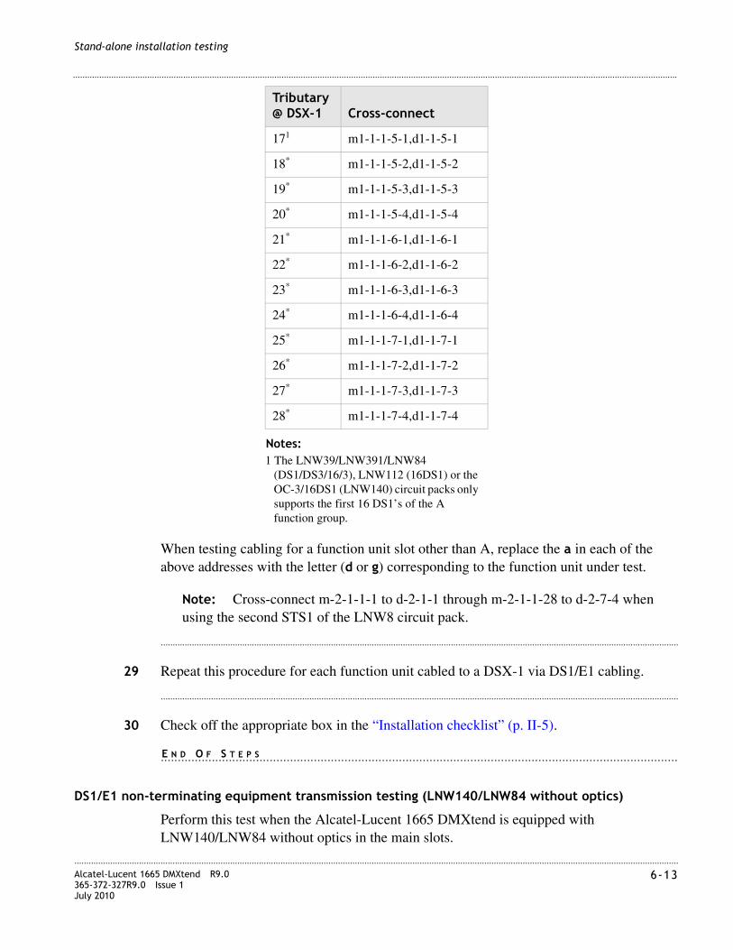
............................................................................................................................................................................................................................................................Alcatel-Lucent 1665 DMXtend R9.0365-372-327R9.0 Issue 1July 2010
6-13
............................................................................................................................................................................................................................................................
Stand-alone installation testing
When testing cabling for a function unit slot other than A, replace the a in each of the above addresses with the letter (d or g) corresponding to the function unit under test.
Note: Cross-connect m-2-1-1-1 to d-2-1-1 through m-2-1-1-28 to d-2-7-4 when using the second STS1 of the LNW8 circuit pack.
........................................................................................................................................................................................................................
29 Repeat this procedure for each function unit cabled to a DSX-1 via DS1/E1 cabling.
........................................................................................................................................................................................................................
30 Check off the appropriate box in the “Installation checklist” (p. II-5).
........................................................................................................................................................E N D O F S T E P S
DS1/E1 non-terminating equipment transmission testing (LNW140/LNW84 without optics)
Perform this test when the Alcatel-Lucent 1665 DMXtend is equipped with LNW140/LNW84 without optics in the main slots.
171 m1-1-1-5-1,d1-1-5-1
18* m1-1-1-5-2,d1-1-5-2
19* m1-1-1-5-3,d1-1-5-3
20* m1-1-1-5-4,d1-1-5-4
21* m1-1-1-6-1,d1-1-6-1
22* m1-1-1-6-2,d1-1-6-2
23* m1-1-1-6-3,d1-1-6-3
24* m1-1-1-6-4,d1-1-6-4
25* m1-1-1-7-1,d1-1-7-1
26* m1-1-1-7-2,d1-1-7-2
27* m1-1-1-7-3,d1-1-7-3
28* m1-1-1-7-4,d1-1-7-4
Notes:1 The LNW39/LNW391/LNW84
(DS1/DS3/16/3), LNW112 (16DS1) or the OC-3/16DS1 (LNW140) circuit packs only supports the first 16 DS1’s of the A function group.
Tributary @ DSX-1 Cross-connect

............................................................................................................................................................................................................................................................6-14 Alcatel-Lucent 1665 DMXtend R9.0
365-372-327R9.0 Issue 1July 2010
............................................................................................................................................................................................................................................................
Stand-alone installation testing
Facility Loopback testing allows the installer to verify the electrical cabling to the Alcatel-Lucent 1665 DMXtend NE. Follow the procedure below to perform a facility loopback test at the Alcatel-Lucent 1665 DMXtend shelf.
To test cabling to the DSX-1, use a DS1/E1 test set to transmit and receive toward the facility loopback.
Perform the following tests for each DS1/E1 circuit cabled to the Alcatel-Lucent 1665 DMXtend.
........................................................................................................................................................................................................................
1 Select Fault > Analysis > Loopback...
........................................................................................................................................................................................................................
2 Choose the DS1/E1 port to test and click Select.
........................................................................................................................................................................................................................
3 Select Operate and Loopback Type: Facility and click Apply.
........................................................................................................................................................................................................................
4 Once the loopback is up, a test signal is generated at the DS1/E1 terminating equipment which will verify that the cabling is correct.
Note: A test set can be applied at the DSX-1 to test cabling toward the facility loopback.
........................................................................................................................................................................................................................
5 Once the test is complete, remove the loopback.
Select Fault > Analysis > Loopback...
........................................................................................................................................................................................................................
6 Choose the DS1/E1 port to test and click Select.
........................................................................................................................................................................................................................
7 Select Release and Loopback Type: Facility and click Apply.
........................................................................................................................................................................................................................
8 Repeat Step 1 through Step 7 for each DS1/E1 cabled to the DSX-1.
........................................................................................................................................................................................................................
9 Check off the appropriate box in the “Installation checklist” (p. II-5).
........................................................................................................................................................E N D O F S T E P S

............................................................................................................................................................................................................................................................Alcatel-Lucent 1665 DMXtend R9.0365-372-327R9.0 Issue 1July 2010
6-15
............................................................................................................................................................................................................................................................
Stand-alone installation testing
DS3/EC1 testing
DS3/EC1 testing procedure
Perform the following steps for all Alcatel-Lucent 1665 DMXtend shelf function unit slots containing the following circuit packs and cabled to the DSX:
– LNW16 (12DS3/EC1)
– LNW18 (12TMUX)
– LNW19B (48DS3/EC1)
– LNW20 (48TMUXDS3EC1)
– LNW39/LNW391 (DS1/DS3/16/3)
– LNW111 (3 DS3)
– LNW84 (3 DS3)
If the Alcatel-Lucent 1665 DMXtend is cabled to some other type of DS3/EC1 terminating equipment, use this procedure by substituting these ports for the DSX-3 ports called out in the procedure.
If the Alcatel-Lucent 1665 DMXtend shelf is not fully populated, it may be necessary to move the circuit pack(s) from slot to slot in order to test all DS3/EC1 cabling.
This procedure requires the use of a DS3 test set.
Note: The LNW16/LNW19B circuit packs are provisioned on a “per-port” basis for DS3 or EC1. The default setting for all ports is DS3. Tests in the section will verify proper cabling by using a DS3 test set with all ports provisioned as DS3.
The LNW39/LMW391/LNW84 (DS1/DS3/16/3) pack’s DS3 portion is only provisionable for DS3.
Verify provisioning
This procedure will verify provisioning.
........................................................................................................................................................................................................................
1 For the LNW16 or LNW19B, verify that all ports are provisioned for DS3.Use the GUI View:Equipment command.
........................................................................................................................................................................................................................
2 Click on each DS3 port
Result: All ports are provisioned as DS3.

............................................................................................................................................................................................................................................................6-16 Alcatel-Lucent 1665 DMXtend R9.0
365-372-327R9.0 Issue 1July 2010
............................................................................................................................................................................................................................................................
Stand-alone installation testing
........................................................................................................................................................................................................................
3 To provision a port to DS3, from the GUI choose Configuration:Equipment Select the DS3 port, click Select.
........................................................................................................................................................................................................................
4 Choose Electrical Interface Type = DS3:Signal Format = Framed.
........................................................................................................................................................................................................................
5 Click Apply to issue the command.
........................................................................................................................................................................................................................
6 Repeat Step 1 through Step 5 for each Function Group equipped with LNW16 or LNW19B circuit pack(s).
........................................................................................................................................................E N D O F S T E P S
Transmission test
Perform the remaining steps in this procedure for all Function Groups equipped with LNW16 (12DS3/EC1), LNW19B (48DS3/EC1) or LNW39/LNW391/LNW84 (DS1/DS3/16/3) circuit packs.
........................................................................................................................................................................................................................
1 Set the DS3 test set to transmit and receive a framed Pseudo Random Bit Stream (PRBS) DS3 test signal CBIT or M13 (M13 is default).
M13 should be used to test LNW39/LNW391/LNW84 (DS1/DS3/16/3).
........................................................................................................................................................................................................................
2 Connect a cable from the DS3 test set transmit connection to the IN jack of the DSX-3 associated with the first DS3 tributary of the Alcatel-Lucent 1665 DMXtend function unit slot to be tested.
........................................................................................................................................................................................................................
3 Connect a cable from the DS3 test set receive connection to the OUT jack of the DSX-3 associated with the first DS3 tributary of the Alcatel-Lucent 1665 DMXtend function unit slot to be tested.
Result: The DS3 test set should indicate a blue (AIS) signal is being received for a DS3 pack.
........................................................................................................................................................................................................................
4 Use the GUI command to enter cross-connects.

............................................................................................................................................................................................................................................................Alcatel-Lucent 1665 DMXtend R9.0365-372-327R9.0 Issue 1July 2010
6-17
............................................................................................................................................................................................................................................................
Stand-alone installation testing
........................................................................................................................................................................................................................
5 Click Configuration:Cross-Connections.
........................................................................................................................................................................................................................
6 Select Create a new cross-connection.
........................................................................................................................................................................................................................
7 Select Next.
........................................................................................................................................................................................................................
8 Select Rate= STS1: Type of Cross-connect= UPSR Add/Drop.
........................................................................................................................................................................................................................
9 Select Next.
........................................................................................................................................................................................................................
10 Select main1-1-1 to [b,d,g]1-1.
........................................................................................................................................................................................................................
11 Click Finish to issue the command.
Requirement: The DS3 test set should indicate it is receiving an error free PRBS signal. To check that the port on the DS3 pack is receiving the signal, verify that the port has transitioned to an “in service” state with the View:Equipment command.
Result: The DS3 provisioning will be displayed, along with the port state (last parameter). A port state of "IS" indicates that the pack is receiving a good signal to the port
........................................................................................................................................................................................................................
12 While observing the error-free transmission, grasp the DS3 cable about two inches from the BNC connector head and gently rotate (twist) the cable in a clockwise and counter-clockwise direction about 45 degrees (gently).
Result: If any errors are detected while performing this "wiggle test", the BNC connector must be cut off and replaced.
If an error free signal is not received:
• Check the LBOs settings using the View:Equipment command (see “Setting DS1/E1 LBOs” (p. 6-5).
• Verify that the pack is provisioned for the framing format being sent from the test set, CBIT or M13.

............................................................................................................................................................................................................................................................6-18 Alcatel-Lucent 1665 DMXtend R9.0
365-372-327R9.0 Issue 1July 2010
............................................................................................................................................................................................................................................................
Stand-alone installation testing
• Verify that the port is provisioned for DS3.
• Check the DS3/EC1 cabling for proper connections.
........................................................................................................................................................................................................................
13 Use the GUI command to delete the cross-connect.
........................................................................................................................................................................................................................
14 Click Configuration:Cross-Connections.
........................................................................................................................................................................................................................
15 Select Delete legs of an Existing cross-connection.
........................................................................................................................................................................................................................
16 Select Next.
........................................................................................................................................................................................................................
17 Click on the main (OC-N).
........................................................................................................................................................................................................................
18 Double click on port 1 (OC-N).
........................................................................................................................................................................................................................
19 Select Next.
........................................................................................................................................................................................................................
20 Select Next.
........................................................................................................................................................................................................................
21 Select Finish.
........................................................................................................................................................................................................................
22 Click Yes.
........................................................................................................................................................................................................................
23 Click Yes.
Result: The DS3 test set should indicate a blue (AIS) signal is being received in place of the PRBS signal.
........................................................................................................................................................................................................................
24 Remove the test set connections from the DSX-3.

............................................................................................................................................................................................................................................................Alcatel-Lucent 1665 DMXtend R9.0365-372-327R9.0 Issue 1July 2010
6-19
............................................................................................................................................................................................................................................................
Stand-alone installation testing
........................................................................................................................................................................................................................
25 Use the e GUI to send an upd-sys command.
........................................................................................................................................................................................................................
26 Click on Configuration > Update System > Update All.
........................................................................................................................................................................................................................
27 Repeat Step 2 through Step 26 to test cabling to each of the remaining DS3 tributaries of the function unit. Substitute the following address.
When testing cabling for a function unit slot other than d, replace the d in each of the above addresses with the letter (b or g) corresponding to the function unit slot under test.
Note: If the mains are equipped with LNW141s, LNW140s or LNW84s and either a LNW19B are equipped in the function slots then m1-1-13, d1-13 through m1-1-48, d1-48 should be tested.
........................................................................................................................................................................................................................
28 Repeat this procedure for each function unit slot cabled to a DSX-3 via DS3/EC1 cabling.
Tributary @ DSX-3
Cross-connect address
21
Notes:1 The LNW39/LNW391/LNW84
(DS1/DS3/16/3) circuit pack only supports 3 DS3’s from the b function group
m1-1-2,d1-2
3* m1-1-3,d1-3
4 m1-1-4,d1-4
5 m1-1-5,d1-5
6 m1-1-6,d1-6
7 m1-1-7,d1-7
8 m1-1-8,d1-8
9 m1-1-9,d1-9
10 m1-1-10,d1-10
11 m1-1-11,d1-11
12 m1-1-12,d1-12

............................................................................................................................................................................................................................................................6-20 Alcatel-Lucent 1665 DMXtend R9.0
365-372-327R9.0 Issue 1July 2010
............................................................................................................................................................................................................................................................
Stand-alone installation testing
........................................................................................................................................................................................................................
29 Check off the appropriate box in the “Installation checklist” (p. II-5).
........................................................................................................................................................E N D O F S T E P S
DS3 terminating equipment loopback testing (LNW84 without optics)
Perform this test when the Alcatel-Lucent 1665 DMXtend is equipped with LNW84 without optics in the main slots.
Facility loopback testing allows the installer to verify the electrical cabling to the Alcatel-Lucent 1665 DMXtend NE. Follow the procedure below to perform a facility loopback test at the Alcatel-Lucent 1665 DMXtend shelf. When the Alcatel-Lucent 1665 DMXtend is cabled to other DS3 terminating equipment, in order to complete the loopback testing, it will be necessary to contact the Customer Network Control Center and have a signal established at the port(s) under test.
To test cabling to the DSX-3, use a DS3 test set to transmit and receive toward the facility loopback.
Perform the following tests for each DS3 circuit cabled to the Alcatel-Lucent 1665 DMXtend.
........................................................................................................................................................................................................................
1 Select Fault > Analysis > Loopback...
........................................................................................................................................................................................................................
2 Choose the DS3 port to test and click Select.
........................................................................................................................................................................................................................
3 Select Operate and Loopback Type: Facility and click Apply.
........................................................................................................................................................................................................................
4 Once the loopback is up, a test signal is generated at the DS3 terminating equipment which will verify that the cabling is correct.
Note: A test set can be applied at the DSX-3 to test cabling toward the facility loopback.
........................................................................................................................................................................................................................
5 While observing the error free transmission, grasp the DS3 cable about two inches from the BNC connector head and gently rotate (twist) the cable in a clockwise and counter clockwise direction about 45 degrees (gently).
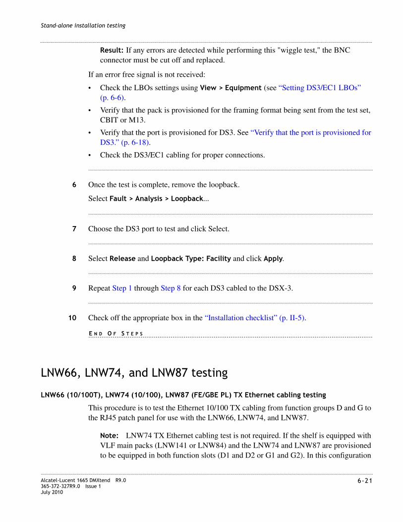
............................................................................................................................................................................................................................................................Alcatel-Lucent 1665 DMXtend R9.0365-372-327R9.0 Issue 1July 2010
6-21
............................................................................................................................................................................................................................................................
Stand-alone installation testing
Result: If any errors are detected while performing this "wiggle test," the BNC connector must be cut off and replaced.
If an error free signal is not received:
• Check the LBOs settings using View > Equipment (see “Setting DS3/EC1 LBOs” (p. 6-6).
• Verify that the pack is provisioned for the framing format being sent from the test set, CBIT or M13.
• Verify that the port is provisioned for DS3. See “Verify that the port is provisioned for DS3.” (p. 6-18).
• Check the DS3/EC1 cabling for proper connections.
........................................................................................................................................................................................................................
6 Once the test is complete, remove the loopback.
Select Fault > Analysis > Loopback...
........................................................................................................................................................................................................................
7 Choose the DS3 port to test and click Select.
........................................................................................................................................................................................................................
8 Select Release and Loopback Type: Facility and click Apply.
........................................................................................................................................................................................................................
9 Repeat Step 1 through Step 8 for each DS3 cabled to the DSX-3.
........................................................................................................................................................................................................................
10 Check off the appropriate box in the “Installation checklist” (p. II-5).
........................................................................................................................................................E N D O F S T E P S.
LNW66, LNW74, and LNW87 testing
LNW66 (10/100T), LNW74 (10/100), LNW87 (FE/GBE PL) TX Ethernet cabling testing
This procedure is to test the Ethernet 10/100 TX cabling from function groups D and G to the RJ45 patch panel for use with the LNW66, LNW74, and LNW87.
Note: LNW74 TX Ethernet cabling test is not required. If the shelf is equipped with VLF main packs (LNW141 or LNW84) and the LNW74 and LNW87 are provisioned to be equipped in both function slots (D1 and D2 or G1 and G2). In this configuration

............................................................................................................................................................................................................................................................6-22 Alcatel-Lucent 1665 DMXtend R9.0
365-372-327R9.0 Issue 1July 2010
............................................................................................................................................................................................................................................................
Stand-alone installation testing
the backplane electrical ports cannot be used, only the SFP-based faceplate ports are used.
The following cables are required to test the Ethernet cabling.
Ethernet port assignment verification testing
........................................................................................................................................................................................................................
1 Connect the Front CIT cable between the PC and the CIT/RS 232 port of the System Controller and login to the shelf using the serial connection and the GUI options on WaveStar® CIT.
........................................................................................................................................................................................................................
2 Identify the function groups that contain LNW66, LNW74, or LNW87 circuit packs with cabling for testing.
........................................................................................................................................................................................................................
3 Identify the RJ45 patch panel associated with the function groups identified above.
........................................................................................................................................................................................................................
4 Connect the RJ45 cable from the first RJ45 on the patch panel to the Ethernet port on your PC.
........................................................................................................................................................................................................................
5 Watch for the link LED to light on the PC’s Ethernet card or wait for 30 seconds and then disconnect the RJ45 cable from the patch panel.
........................................................................................................................................................................................................................
6 The Fault LED will start flashing on the LNW66, LNW74, or LNW87 and the GUI will alarm the port under test and display a Critical Alarm inc.FE-LAN LOS in the Alarm List.
........................................................................................................................................................................................................................
7 Verify that the port you are connected to matches the one listed in the aid of the FE-LAN LOS alarm output.
Cable Length Quantity
Front CIT(RS-232) Cable (C848748869)
8’-0" 1
LAN 10BaseT Straight-through Cable
As required to reach from front of Alcatel-Lucent 1665 DMXtend to the RJ45 patch panel
2

............................................................................................................................................................................................................................................................Alcatel-Lucent 1665 DMXtend R9.0365-372-327R9.0 Issue 1July 2010
6-23
............................................................................................................................................................................................................................................................
Stand-alone installation testing
........................................................................................................................................................................................................................
8 Select Configuration > Update System > Update All...
........................................................................................................................................................................................................................
9 Click Yes to issue the command.
........................................................................................................................................................................................................................
10 The flashing fault LED on the LNW66, LNW74, or LNW87 will clear.
........................................................................................................................................................................................................................
11 Connect the RJ45 cable to the next jack on the RJ45 patch panel and repeat starting at Step 4 until all connected jacks have been tested.
........................................................................................................................................................E N D O F S T E P S
Ethernet port wiring verification testing
Note: Continue with the following section only for LNW66 circuit packs. Testing is complete for LNW74 and LNW87 packs!
........................................................................................................................................................................................................................
1 If not still connected serially from the last procedure then, connect the Front CIT cable between the PC and the CIT/RS-232 jack of System Controller and login to the shelf using the serial connection.
........................................................................................................................................................................................................................
2 Select Configuration > Data > Create Virtual Switch.
........................................................................................................................................................................................................................
3 Choose the LNW66 that is being tested.
........................................................................................................................................................................................................................
4 Click Select.
........................................................................................................................................................................................................................
5 Enter Virtual Switch ID: 1.
........................................................................................................................................................................................................................
6 Under Ethernet (LAN) Ports, click Select All.
........................................................................................................................................................................................................................
7 Click Apply.

............................................................................................................................................................................................................................................................6-24 Alcatel-Lucent 1665 DMXtend R9.0
365-372-327R9.0 Issue 1July 2010
............................................................................................................................................................................................................................................................
Stand-alone installation testing
........................................................................................................................................................................................................................
8 Connect a RJ45 Ethernet cable from the LAN port on the LNW2 SYSCTL to the first position on the RJ45 Ethernet patch panel.
........................................................................................................................................................................................................................
9 Connect a second RJ45 Ethernet cable from the PC Ethernet port to the second position on the RJ45 Ethernet patch panel.
........................................................................................................................................................................................................................
10 Watch for the link LED to light on the PC’s Ethernet card or wait for 30 seconds.
........................................................................................................................................................................................................................
11 Login to the shelf using the OSI connection.
Result: Successful login to the Alcatel-Lucent 1665 DMXtend.
........................................................................................................................................................................................................................
12 Log out of the Alcatel-Lucent 1665 DMXtend shelf.
........................................................................................................................................................................................................................
13 At the RJ45 Ethernet patch panel disconnect the RJ45 Ethernet cable run to the PC Ethernet port and connect it to the next position on the RJ45 Ethernet patch panel to be tested.
........................................................................................................................................................................................................................
14 Ignore the flashing fault LED on the Ethernet circuit pack and any alarms on the shelf.
........................................................................................................................................................................................................................
15 Watch for the link LED to light on the PC’s Ethernet card or wait for 30 seconds.
........................................................................................................................................................................................................................
16 Login to the shelf using the OSI connection.
Result: Successful login to the Alcatel-Lucent 1665 DMXtend.
........................................................................................................................................................................................................................
17 Log out of the Alcatel-Lucent 1665 DMXtend shelf.
........................................................................................................................................................................................................................
18 Repeat this procedure starting at Step 13 for the remaining Ethernet connections on the RJ45 patch panel connected to the LNW66 under test, then continue on to Step 19.

............................................................................................................................................................................................................................................................Alcatel-Lucent 1665 DMXtend R9.0365-372-327R9.0 Issue 1July 2010
6-25
............................................................................................................................................................................................................................................................
Stand-alone installation testing
........................................................................................................................................................................................................................
19 Disconnect the PC from the RJ45 patch panel and the Alcatel-Lucent 1665 DMXtend LAN port from the RJ45 patch panel.
........................................................................................................................................................................................................................
20 If not still connected from the previous procedure. Connect the Front CIT cable between the PC and the CIT/RS 232 jack of System Controller and login to the shelf using the serial connection.
........................................................................................................................................................................................................................
21 Select Configuration > Update System... > Update All.
Result: The flashing fault LED on the Ethernet circuit pack will clear and any alarms on the Alcatel-Lucent 1665 DMXtend shelf will also clear.
........................................................................................................................................................................................................................
22 Select Configuration > Data > Delete Virtual Switch.
........................................................................................................................................................................................................................
23 Choose the LNW66 circuit pack and click Select.
........................................................................................................................................................................................................................
24 Select the VRTSW ID and click Apply.
........................................................................................................................................................................................................................
25 Log out and disconnect the PC from the Alcatel-Lucent 1665 DMXtend serial port.
........................................................................................................................................................................................................................
26 Repeat this procedure for every slot containing and LNW66.
........................................................................................................................................................................................................................
27 Check off the appropriate box in the “Installation checklist” (p. II-5).
........................................................................................................................................................E N D O F S T E P S

............................................................................................................................................................................................................................................................6-26 Alcatel-Lucent 1665 DMXtend R9.0
365-372-327R9.0 Issue 1July 2010
............................................................................................................................................................................................................................................................
Stand-alone installation testing
OC-3 low-speed testing
OC-3 low-speed LNW37 PTM testing procedure
Perform the following steps for all Alcatel-Lucent 1665 DMXtend shelf function unit or growth slots containing LNW37 (OC-3 OLIU) circuit pack.
Note: When reference is made to optical fiber loopback connections to IN and OUT on the OLIU, make the connections at the LGX equipment in order to verify correct installation and labeling of the fibers.
Note: Equip all ports with PTMs provided. If all ports don’t have PTMs, but have associated fibers, then move PTMs to ports that are fibered.
LBOs are installed on the OLIU faceplate IN port.
........................................................................................................................................................................................................................
1 Beginning from the Top (G) side of the Alcatel-Lucent 1665 DMXtend shelf, locate the first function unit slot position that contains an LNW37 circuit pack.
........................................................................................................................................................................................................................
2 Insert a 15-dB LC-type LBO into the top IN connector (port 1) of the first PTM equipped. See Appendix C, “Installing fiber connectors and LBOs”.
Connect the fibers labeled IN and OUT from the LGX to the OLIU (port 1).
........................................................................................................................................................................................................................
3 Connect the Port 1 IN connector to the Port 1 OUT connector (at the LGX) of the OC-3 OLIU, using an optical fiber jumper cable. See Appendix A, “Fiber cleaning” for proper fiber cleaning instructions.
Result: The FAULT LED on the OC-3 OLIU will begin flashing and the MN and NE LEDs should be lit on the SYSCTL circuit pack.
After approximately 20 seconds the flashing FAULT LED should extinguish on the OC-3 OLIU and the FAULT, MJ and NE LEDs should be lit on the SYSCTL circuit pack.
CAUTION
Laser Safety
When connecting fiber loops between the IN and OUT ports on optical circuit packs, always connect to the IN port first and then the OUT port. This will prevent any optical radiation from being present at the fiber end.For more detailed information and safety precautions, see Chapter 1, “Safety”.
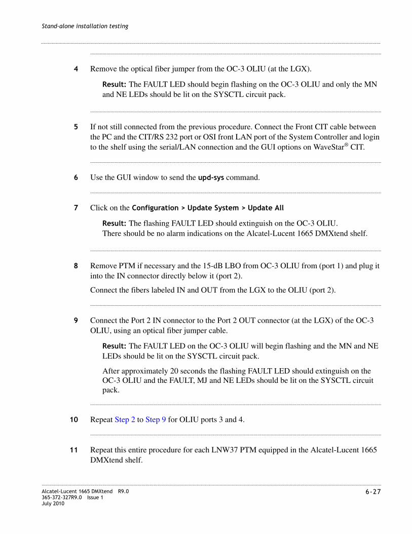
............................................................................................................................................................................................................................................................Alcatel-Lucent 1665 DMXtend R9.0365-372-327R9.0 Issue 1July 2010
6-27
............................................................................................................................................................................................................................................................
Stand-alone installation testing
........................................................................................................................................................................................................................
4 Remove the optical fiber jumper from the OC-3 OLIU (at the LGX).
Result: The FAULT LED should begin flashing on the OC-3 OLIU and only the MN and NE LEDs should be lit on the SYSCTL circuit pack.
........................................................................................................................................................................................................................
5 If not still connected from the previous procedure. Connect the Front CIT cable between the PC and the CIT/RS 232 port or OSI front LAN port of the System Controller and login to the shelf using the serial/LAN connection and the GUI options on WaveStar® CIT.
........................................................................................................................................................................................................................
6 Use the GUI window to send the upd-sys command.
........................................................................................................................................................................................................................
7 Click on the Configuration > Update System > Update All
Result: The flashing FAULT LED should extinguish on the OC-3 OLIU.There should be no alarm indications on the Alcatel-Lucent 1665 DMXtend shelf.
........................................................................................................................................................................................................................
8 Remove PTM if necessary and the 15-dB LBO from OC-3 OLIU from (port 1) and plug it into the IN connector directly below it (port 2).
Connect the fibers labeled IN and OUT from the LGX to the OLIU (port 2).
........................................................................................................................................................................................................................
9 Connect the Port 2 IN connector to the Port 2 OUT connector (at the LGX) of the OC-3 OLIU, using an optical fiber jumper cable.
Result: The FAULT LED on the OC-3 OLIU will begin flashing and the MN and NE LEDs should be lit on the SYSCTL circuit pack.
After approximately 20 seconds the flashing FAULT LED should extinguish on the OC-3 OLIU and the FAULT, MJ and NE LEDs should be lit on the SYSCTL circuit pack.
........................................................................................................................................................................................................................
10 Repeat Step 2 to Step 9 for OLIU ports 3 and 4.
........................................................................................................................................................................................................................
11 Repeat this entire procedure for each LNW37 PTM equipped in the Alcatel-Lucent 1665 DMXtend shelf.
............................................................................................................................................................................................................................................................6-28 Alcatel-Lucent 1665 DMXtend R9.0
365-372-327R9.0 Issue 1July 2010
............................................................................................................................................................................................................................................................
Stand-alone installation testing
........................................................................................................................................................................................................................
12 Replace all protective dust covers on the LNW37 PTM connectors (OLIU and LGX), that were removed to perform this procedure.
........................................................................................................................................................................................................................
13 Check off the appropriate box in the “Installation checklist” (p. II-5).
........................................................................................................................................................E N D O F S T E P S
OC-3 low-speed LNW45 or LNW55 PTM testing procedure
Perform the following steps for all Alcatel-Lucent 1665 DMXtend shelf function unit or growth slots containing LNW45 (OC3) or LNW55 (with 12 OC3 PTMs) OLIU circuit packs.
Note: The LNW55 circuit packs requires the LNW141 or LNW84 installed in the main slots to operate in a Alcatel-Lucent 1665 DMXtend shelf.
Note: When reference is made to optical fiber loopback connections to IN and OUT on the OLIU, make the connections at the LGX equipment in order to verify correct installation and labeling of the fibers.
Note: Equip all ports with PTMs provided. If all ports don’t have PTMs, but have associated fibers, then move PTMs to ports that are fibered.
LBOs are installed on the OLIU faceplate IN port.
........................................................................................................................................................................................................................
1 Beginning from the Top (G) of the Alcatel-Lucent 1665 DMXtend shelf, locate the first function unit slot position that contains an LNW45 or LNW55 circuit pack.
........................................................................................................................................................................................................................
2 Insert a 15-dB LC-type LBO into the top IN connector (port 1) of the first PTM equipped. See Appendix C, “Installing fiber connectors and LBOs”.
Connect the fibers labeled IN and OUT from the LGX to the OLIU (port 1).
CAUTION
Laser Safety
When connecting fiber loops between the IN and OUT ports on optical circuit packs, always connect to the IN port first and then the OUT port. This will prevent any optical radiation from being present at the fiber end. For more detailed information and safety precautions, see Chapter 1, “Safety”.

............................................................................................................................................................................................................................................................Alcatel-Lucent 1665 DMXtend R9.0365-372-327R9.0 Issue 1July 2010
6-29
............................................................................................................................................................................................................................................................
Stand-alone installation testing
........................................................................................................................................................................................................................
3 Connect the Port 1 IN connector to the Port 1 OUT connector (at the LGX) of the OC-3 OLIU, using an optical fiber jumper cable. See Appendix A, “Fiber cleaning” for proper fiber cleaning instructions.
Result: The FAULT LED on the OC-3 OLIU will begin flashing and the MN and NE LEDs should be lit on the SYSCTL circuit pack.
After approximately 20 seconds the flashing FAULT LED should extinguish on the OC-3 OLIU and the FAULT, MJ and NE LEDs should be lit on the SYSCTL circuit pack.
........................................................................................................................................................................................................................
4 Remove the optical fiber jumper from the OC-3 OLIU (at the LGX).
Result: The FAULT LED should begin flashing on the OC-3 OLIU and only the MN and NE LEDs should be lit on the SYSCTL circuit pack.
........................................................................................................................................................................................................................
5 If not still connected from the previous procedure. Connect the Front CIT cable between the PC and the CIT/RS 232 port or OSI front LAN port of the System Controller and login to the shelf using the serial/LAN connection and the GUI options on WaveStar® CIT.
........................................................................................................................................................................................................................
6 Use the GUI window to send the upd-sys command.
........................................................................................................................................................................................................................
7 Click on the Configuration > Update System > Update All
Result: The flashing FAULT LED should extinguish on the OC-3 OLIU.There should be no alarm indications on the Alcatel-Lucent 1665 DMXtend shelf.
........................................................................................................................................................................................................................
8 Remove PTM if necessary and the 15-dB LBO from OC-3 OLIU from (port 1) and plug it into the IN connector directly below it (port 2).
........................................................................................................................................................................................................................
9 Connect the fibers labeled IN and OUT from the LGX to the OLIU (port 2).
........................................................................................................................................................................................................................
10 Connect the Port 2 IN connector to the Port 2 OUT connector (at the LGX) of the OC-3 OLIU, using an optical fiber jumper cable.

............................................................................................................................................................................................................................................................6-30 Alcatel-Lucent 1665 DMXtend R9.0
365-372-327R9.0 Issue 1July 2010
............................................................................................................................................................................................................................................................
Stand-alone installation testing
Result: The FAULT LED on the OC-3 OLIU will begin flashing and the MN and NE LEDs should be lit on the SYSCTL circuit pack.
After approximately 20 seconds the flashing FAULT LED should extinguish on the OC-3 OLIU and the FAULT, MJ and NE LEDs should be lit on the SYSCTL circuit pack.
........................................................................................................................................................................................................................
11 Repeat Step 2 to Step 10 for OLIU for the remaining ports on the LNW45 and the LNW55 circuit packs.
........................................................................................................................................................................................................................
12 Repeat this entire procedure for each LNW45 and LNW55 equipped in the Alcatel-Lucent 1665 DMXtend shelf.
........................................................................................................................................................................................................................
13 Replace all protective dust covers on the LNW45 and LNW55 PTM connectors (OLIU and LGX), that were removed to perform this procedure.
........................................................................................................................................................................................................................
14 Check off the appropriate box in the “Installation checklist” (p. II-5).
........................................................................................................................................................E N D O F S T E P S
OC-12 low-speed testing
OC-12 low-speed LNW49 and LNW55 PTM testing procedure
Perform the following steps for all Alcatel-Lucent 1665 DMXtend shelf function unit or growth slots containing OC-12 (LNW49 or LNW55) OLIU circuit packs...
Note: The LNW55 circuit pack requires the LNW141 or LNW84 installed in the main slots to operate in a Alcatel-Lucent 1665 DMXtend shelf.
CAUTIONLaser SafetyWhen connecting fiber loops between the IN and OUT ports on optical circuit packs, always connect to the IN port first and then the OUT port. This will prevent any optical radiation from being present at the fiber end.For more detailed information and safety precautions, see Chapter 1, “Safety”.
............................................................................................................................................................................................................................................................Alcatel-Lucent 1665 DMXtend R9.0365-372-327R9.0 Issue 1July 2010
6-31
............................................................................................................................................................................................................................................................
Stand-alone installation testing
Note: When reference is made to optical fiber loopback connections to IN and OUT on the OLIU, make the connections at the LGX equipment in order to verify correct installation and labeling of the fibers.
Note: Equip all ports with PTMs provided. If all ports don’t have PTMs, but have associated fibers, then move PTMs to ports that are fibered. LBOs are installed on the OLIU faceplate IN port.
........................................................................................................................................................................................................................
1 Beginning from the top (G) of the Alcatel-Lucent 1665 DMXtend shelf, locate the first function unit slot that contains an OC-12 OLIU circuit pack.
........................................................................................................................................................................................................................
2 Insert a 15-dB LC-type LBO into the top IN connector (port 1) of the OC-12 OLIU. See Appendix C, “Installing fiber connectors and LBOs”.
Connect the fibers labeled IN and OUT from the LGX to the OLIU (port 1).
........................................................................................................................................................................................................................
3 Connect the Port 1 IN connector to the Port 1 OUT connector (at the LGX) of the OC-12 OLIU, using an optical fiber jumper cable. See Appendix A, “Fiber cleaning” for proper fiber cleaning instructions.
Result: The FAULT LED on the OC-12 OLIU will begin flashing and the MN and IN NE LEDs should be lit on the SYSCTL circuit pack.
After approximately 20 seconds the flashing FAULT LED should extinguish on the OC-12 OLIU and the FAULT, MJ and NE LEDs should be lit on the SYSCTL circuit pack.
........................................................................................................................................................................................................................
4 Remove the optical fiber jumper from the OC-12 OLIU (at the LGX).
Result: The FAULT LED should begin flashing on the OC-12 OLIU and only the MN and NE LEDs should be lit on the SYSCTL circuit pack.
........................................................................................................................................................................................................................
5 If not still connected from the previous procedure. Connect the Front CIT cable between the PC and the CIT/RS 232 port or OSI front LAN port of the System Controller and login to the shelf using the serial/LAN connection and the GUI options on WaveStar® CIT.
........................................................................................................................................................................................................................
6 Use the GUI window to send the upd-sys command.

............................................................................................................................................................................................................................................................6-32 Alcatel-Lucent 1665 DMXtend R9.0
365-372-327R9.0 Issue 1July 2010
............................................................................................................................................................................................................................................................
Stand-alone installation testing
........................................................................................................................................................................................................................
7 Click on the Configuration > Update System > Update All.
Result: The flashing FAULT LED should extinguish on the OC-12 OLIU.There should be no alarm indications on the Alcatel-Lucent 1665 DMXtend shelf.
........................................................................................................................................................................................................................
8 Remove PTM if necessary and the 15-dB LBO from OC-12 OLIU from (port 1) and plug it into the IN connector directly below it (port 2).
Connect the fibers labeled IN and OUT from the LGX to the OLIU (port 2).
........................................................................................................................................................................................................................
9 Connect the Port 2 IN connector to the Port 2 OUT connector (at the LGX) of the OC-12 OLIU, using an optical fiber jumper cable.
Result: The FAULT LED on the OC-12 OLIU will begin flashing and the MN and NE LEDs should be lit on the SYSCTL circuit pack.
After approximately 20 seconds the flashing FAULT LED should extinguish on the OC-12 OLIU and the FAULT, MJ and NE LEDs should be lit on the SYSCTL circuit pack.
........................................................................................................................................................................................................................
10 Repeat Step 2 to Step 9 for all OLIU ports.
........................................................................................................................................................................................................................
11 Repeat this entire procedure for each LNW49 or LNW55 PTM equipped in the Alcatel-Lucent 1665 DMXtend shelf.
........................................................................................................................................................................................................................
12 Replace all protective dust covers on the LNW49 or LNW55 PTM OC-12 OLIU connectors (OLIU and LGX), that were removed to perform this procedure.
........................................................................................................................................................................................................................
13 Check off the appropriate box in the “Installation checklist” (p. II-5).
........................................................................................................................................................E N D O F S T E P S

............................................................................................................................................................................................................................................................Alcatel-Lucent 1665 DMXtend R9.0365-372-327R9.0 Issue 1July 2010
6-33
............................................................................................................................................................................................................................................................
Stand-alone installation testing
OC-48 low-speed testing
OC-48 low-speed testing procedure
Perform the following steps for all Alcatel-Lucent 1665 DMXtend shelf function unit or growth slots containing OC-48 (LNW31) OLIU circuit packs.
Note: When reference is made to optical fiber loopback connections to IN and OUT on the OLIU, make the connections at the LGX equipment in order to verify correct installation and labeling of the fibers.
LBOs are installed on the OLIU faceplate IN port.
........................................................................................................................................................................................................................
1 Beginning from the top (G) of the Alcatel-Lucent 1665 DMXtend shelf, locate the first function unit slot that contains an OC-48 OLIU circuit pack.
........................................................................................................................................................................................................................
2 Insert a 15-dB LC-type LBO into the top IN connector of the OC-48 OLIU. See Appendix C, “Installing fiber connectors and LBOs”.
Connect the fibers labeled IN and OUT from the LGX to the OLIU.
........................................................................................................................................................................................................................
3 Connect the Port 1 IN connector to the Port 1 OUT connector (at the LGX) of the OC-48 OLIU, using an optical fiber jumper cable. See Appendix A, “Fiber cleaning” for proper fiber cleaning instructions.
Result: The FAULT LED on the OC-48 OLIU will begin flashing and the MN and NE LEDs should be lit on the SYSCTL circuit pack.
After approximately 20 seconds the flashing FAULT LED should extinguish on the OC-48 OLIU and the FAULT, MJ and NE LEDs should be lit on the SYSCTL circuit pack.
........................................................................................................................................................................................................................
4 Remove the optical fiber jumper from the OC-48 OLIU (at the LGX).
CAUTION
Laser Safety
When connecting fiber loops between the IN and OUT ports on optical circuit packs, always connect to the IN port first and then the OUT port. This will prevent any optical radiation from being present at the fiber end.For more detailed information and safety precautions, see Chapter 1, “Safety”.

............................................................................................................................................................................................................................................................6-34 Alcatel-Lucent 1665 DMXtend R9.0
365-372-327R9.0 Issue 1July 2010
............................................................................................................................................................................................................................................................
Stand-alone installation testing
Result: The FAULT LED should begin flashing on the OC-48 OLIU and only the MN and NE LEDs should be lit on the SYSCTL circuit pack.
........................................................................................................................................................................................................................
5 If not still connected from the previous procedure. Connect the Front CIT cable between the PC and the CIT/RS 232 port or OSI front LAN port of the System Controller and login to the shelf using the serial/LAN connection and the GUI options on WaveStar® CIT.
........................................................................................................................................................................................................................
6 Use the GUI window to send the upd-sys command.
........................................................................................................................................................................................................................
7 Click on the Configuration > Update System > Update All
Result: The flashing FAULT LED should extinguish on the OC-48 OLIU.There should be no alarm indications on the Alcatel-Lucent 1665 DMXtend shelf.
........................................................................................................................................................................................................................
8 Repeat this entire procedure for each low speed OC-48 circuit pack equipped in the Alcatel-Lucent 1665 DMXtend shelf.
........................................................................................................................................................................................................................
9 Remove the 15-dB LBO from the OC-48 OLIU.
........................................................................................................................................................................................................................
10 Replace all protective dust covers on the OC-48 OLIU connectors, that were removed to perform this procedure.
........................................................................................................................................................................................................................
11 Repeat this entire procedure for each LNW31 OC-48 OLIU in the Alcatel-Lucent 1665 DMXtend shelf.
........................................................................................................................................................................................................................
12 Check off the appropriate box in the “Installation checklist” (p. II-5).
........................................................................................................................................................E N D O F S T E P S

............................................................................................................................................................................................................................................................Alcatel-Lucent 1665 DMXtend R9.0365-372-327R9.0 Issue 1July 2010
6-35
............................................................................................................................................................................................................................................................
Stand-alone installation testing
OC-48 PTM equipped low-speed testing procedure
Perform the following steps for all Alcatel-Lucent 1665 DMXtend shelf function unit or growth slots containing LNW62, LNW55, LNW402 (OC-48) OLIU circuit packs.
Note: The LNW62, LNW55 and LNW402 circuit packs require the LNW141 or LNW84 be installed in the main slots to operate in a Alcatel-Lucent 1665 DMXtend shelf.
Note: When reference is made to optical fiber loopback connections to IN and OUT on the OLIU, make the connections at the LGX equipment in order to verify correct installation and labeling of the fibers.
Note: Equip all ports with PTMs provided. If all ports don’t have PTMs, but have associated fibers, then move PTMs to ports that are fibered. LBOs are installed on the OLIU faceplate IN port.
........................................................................................................................................................................................................................
1 Beginning from the top (G) of the Alcatel-Lucent 1665 DMXtend shelf, locate the first function unit slot that contains an OC-48 OLIU circuit pack.
........................................................................................................................................................................................................................
2 Insert a 15-dB LC-type LBO into the top IN connector (port 1) of the OC-48 OLIU. See Appendix C, “Installing fiber connectors and LBOs”.
Connect the fibers labeled IN and OUT from the LGX to the OLIU (port 1).
........................................................................................................................................................................................................................
3 Connect the Port 1 IN connector to the Port 1 OUT connector (at the LGX) of the OC-48 OLIU, using an optical fiber jumper cable. See Appendix A, “Fiber cleaning” for proper fiber cleaning instructions.
Result: The FAULT LED on the OC-48 OLIU will begin flashing and the MN and NE LEDs should be lit on the SYSCTL circuit pack.
After approximately 20 seconds the flashing FAULT LED should extinguish on the OC-48 OLIU and the FAULT, MJ and NE LEDs should be lit on the SYSCTL circuit pack.
CAUTION
Laser Safety
When connecting fiber loops between the IN and OUT ports on optical circuit packs, always connect to the IN port first and then the OUT port. This will prevent any optical radiation from being present at the fiber end.For more detailed information and safety precautions, see Chapter 1, “Safety”.
............................................................................................................................................................................................................................................................6-36 Alcatel-Lucent 1665 DMXtend R9.0
365-372-327R9.0 Issue 1July 2010
............................................................................................................................................................................................................................................................
Stand-alone installation testing
........................................................................................................................................................................................................................
4 Remove the optical fiber jumper from the OC-48 OLIU (at the LGX).
Result: The FAULT LED should begin flashing on the OC-48 OLIU and only the MN and NE LEDs should be lit on the SYSCTL circuit pack.
........................................................................................................................................................................................................................
5 If not still connected from the previous procedure. Connect the Front CIT cable between the PC and the CIT/RS 232 port or OSI front LAN port of the System Controller and login to the shelf using the serial/LAN connection and the GUI options on WaveStar® CIT.
........................................................................................................................................................................................................................
6 Use the GUI window to send the upd-sys command.
........................................................................................................................................................................................................................
7 Click on the Configuration > Update System > Update All.
Result: The flashing FAULT LED should extinguish on the OC-48 OLIU.There should be no alarm indications on the Alcatel-Lucent 1665 DMXtend shelf.
........................................................................................................................................................................................................................
8 Remove PTM if necessary and the 15-dB LBO from OC-48 OLIU from (port 1) and plug it into the IN connector directly below it (port 2).
Connect the fibers labeled IN and OUT from the LGX to the OLIU (port 2).
........................................................................................................................................................................................................................
9 Connect the Port 2 IN connector to the Port 2 OUT connector (at the LGX) of the OC-48 OLIU, using an optical fiber jumper cable.
Result: The FAULT LED on the OC-48 OLIU will begin flashing and the MN and NE LEDs should be lit on the SYSCTL circuit pack.
After approximately 20 seconds the flashing FAULT LED should extinguish on the OC-48 OLIU and the FAULT, MJ and NE LEDs should be lit on the SYSCTL circuit pack.
........................................................................................................................................................................................................................
10 Repeat Step 2 to Step 9 for OLIU ports 3 and 4.
........................................................................................................................................................................................................................
11 Repeat this entire procedure for each LNW62, LNW55, LNW402 PTM equipped in the Alcatel-Lucent 1665 DMXtend shelf.

............................................................................................................................................................................................................................................................Alcatel-Lucent 1665 DMXtend R9.0365-372-327R9.0 Issue 1July 2010
6-37
............................................................................................................................................................................................................................................................
Stand-alone installation testing
........................................................................................................................................................................................................................
12 Replace all protective dust covers on the LNW62, LNW55, LNW402 PTM OC-48 OLIU connectors (OLIU and LGX), that were removed to perform this procedure.
........................................................................................................................................................................................................................
13 Check off the appropriate box in the “Installation checklist” (p. II-5).
........................................................................................................................................................E N D O F S T E P S
LED test
Description
This test verifies proper operation of all LEDs on the Alcatel-Lucent 1665 DMXtend circuit packs. Operation of all the LEDs is necessary to assist in trouble isolation.
Note: If there are any LED failures, determine if the problem is with the circuit pack or shelf and replace the faulty unit.
Steps
........................................................................................................................................................................................................................
1 If not still connected from the previous procedure. Connect the Front CIT cable between the PC and the CIT/RS 232 port or OSI front LAN port of the System Controller and login to the shelf using the serial/LAN connection and the GUI options on WaveStar® CIT.
........................................................................................................................................................................................................................
2 Use the GUI window to send the Test-LED command.
........................................................................................................................................................................................................................
3 Click on the Fault > Test > LED.
........................................................................................................................................................................................................................
4 Select Shelf (Alcatel-Lucent 1665 DMXtend).
........................................................................................................................................................................................................................
5 Click Select.
........................................................................................................................................................................................................................
6 Click Number of Iterations = 1.

............................................................................................................................................................................................................................................................6-38 Alcatel-Lucent 1665 DMXtend R9.0
365-372-327R9.0 Issue 1July 2010
............................................................................................................................................................................................................................................................
Stand-alone installation testing
........................................................................................................................................................................................................................
7 Click OK.
Result: All LEDs on the shelf should light for 10 seconds, then extinguish for 10 seconds, and then the proper LEDs will light to indicate the current status of the shelf.
........................................................................................................................................................................................................................
8 Check off the appropriate box in the “Installation checklist” (p. II-5).
........................................................................................................................................................E N D O F S T E P S
Office alarm test
Description
This test verifies proper operation and wiring of the office alarms in a network equipment building system (NEBS) environment.
Audible and visual reporting of critical, major, minor alarms will be verified.
Prerequisite
The following is a list of items to verify before beginning tests in this section.
• The Alcatel-Lucent 1665 DMXtend Main OLIUs should be optically looped from the previous section. Verify that the Alcatel-Lucent 1665 DMXtend shelf is clear of all alarms (only green LEDs are lighted) prior to and after completing this test.
• The office alarm cable will be temporarily connected during this procedure. Table 6-1, “Office alarm connections” (p. 6-39) lists the office alarms connections.
• It is a requirement that alarms on the Alcatel-Lucent 1665 DMXtend do not affect and are not affected by other equipment via office alarm connections. During this test, the alarm state of other equipment connected to the same office alarms as the Alcatel-Lucent 1665 DMXtend should be examined after creating or clearing every alarm.
• A properly grounded ESD wrist strap must always be worn while handling circuit packs.
• This test should be performed on all shelves where office alarm reporting is required.
• After completing the office alarm test, the Alcatel-Lucent 1665 DMXtend office alarms should be disconnected from the office alarm system for the remainder of the test procedures. This will prevent the office alarms from being activated while performing the other tests in this section

............................................................................................................................................................................................................................................................Alcatel-Lucent 1665 DMXtend R9.0365-372-327R9.0 Issue 1July 2010
6-39
............................................................................................................................................................................................................................................................
Stand-alone installation testing
Table 6-1 Office alarm connections
Steps
........................................................................................................................................................................................................................
1 Connect the office alarm cable to J13 (ALM) on the backplane of the Alcatel-Lucent 1665 DMXtend shelf. If the shelf to be tested is part of a multiple shelf bay arrangement, the office alarm cable connects to shelf 1.
........................................................................................................................................................................................................................
2 Verify that one of the function groups is equipped with any of the following circuit packs.
• LNW7 (28DS1)
• LNW8 (56DS1E1)
• LNW16 (12DS3/EC1)
• LNW18 (12TMUX)
• LNW19B (48DS3/EC1)
• LNW20 (48TMUXDS3EC1)
• LNW39/LNW391 (DS1/DS3/16/3)
• LNW111 (3 DS3)
• LNW112 (16/3 DS1/DS3)
• LNW801 (56 DS1E1)
Conn. Pin# Color Designation Name
J13-J14 1
2
3
4
BL-W
W-BL
O-W
W-O
RYMJV1
RYMJV2
RYMJA1
RYMJA2
Minor Alarm Visible
Minor Alarm Visible Return
Minor Alarm Audible
Minor Alarm Audible Return
5
6
7
8
G-W
W-G
BR-W
W-BR
RYMNV1
RYMNV2
RYMNA1
RYMNA2
Major Alarm Visible
Major Alarm Visible Return
Major Alarm Audible
Major Alarm Audible Return
9
10
11
12
S-W
W-S
BL-R
R-BL
RYCRV1
RYCRV2
RYCRA1
RYCRA2
Critical Alarm Visible
Critical Alarm Visible Return
Critical Alarm Audible
Critical Alarm Audible Return

............................................................................................................................................................................................................................................................6-40 Alcatel-Lucent 1665 DMXtend R9.0
365-372-327R9.0 Issue 1July 2010
............................................................................................................................................................................................................................................................
Stand-alone installation testing
........................................................................................................................................................................................................................
3 Establish a CIT session by following the procedure in Chapter 5, “Stand-alone node setup”, “Use of WaveStar® CIT software” (p. 5-6).
........................................................................................................................................................................................................................
4 Use the GUI to enter the cross-connect command.
........................................................................................................................................................................................................................
5 Click on Configuration > Cross Connection > Create new cross-connection.
........................................................................................................................................................................................................................
6 Click Next.
........................................................................................................................................................................................................................
7 Select UPSR Ring Add/Drop.
........................................................................................................................................................................................................................
8 Select STS1.
........................................................................................................................................................................................................................
9 Click Next.
........................................................................................................................................................................................................................
10 Select the Main Port STS1.
........................................................................................................................................................................................................................
11 Select the Add/Drop port on the function group where the LNW7, LNW8, LNW111, LNW16, LNW18, LNW20, LNW19B, LNW112, LNW801 or LNW39/LNW391 circuit pack is installed.
This command creates a cross-connect to map all 28 DS1s of a 28DS1circuit pack or the first DS-3 of a 12DS3/EC1 for function unit D or G or all 16 DS1s of the LNW39/LNW391 or LNW112 circuit pack in function unit A-1 and/or A-2 slot(s) to the first STS-1 of the Main OLIUs.
........................................................................................................................................................................................................................
12 Click Finish to issue the command.
........................................................................................................................................................................................................................
13 Use the GUI to view the cross-connects.

............................................................................................................................................................................................................................................................Alcatel-Lucent 1665 DMXtend R9.0365-372-327R9.0 Issue 1July 2010
6-41
............................................................................................................................................................................................................................................................
Stand-alone installation testing
........................................................................................................................................................................................................................
14 Click on View > Cross-Connections.
........................................................................................................................................................................................................................
15 Select Shelf.
........................................................................................................................................................................................................................
16 Click Select to issue the command.
Result: The View Cross-Connection window will open displaying the cross-connect that was just entered.
........................................................................................................................................................................................................................
17 Unseat one of the LNW7, LNW8, LNW111, LNW16, LNW18, LNW20, LNW19B, LNW112, LNW801 or LNW39/LMW391 circuit packs from the function group being used.
Result: Activated office alarms: MN visual, MN audible.
Note: Alarms will not be activated until the alarm delay time has passed. The default time is 2 seconds.
........................................................................................................................................................................................................................
18 Press the ACO pushbutton on the SYSCTL.
Result: Activated office alarm: MN visual. The MN audible alarm clears.
........................................................................................................................................................................................................................
19 Disconnect one of the optical fiber jumpers from the OUT port of the OLIU circuit pack in the M1 slot.
Result: Activated office alarms: MJ visual, MJ audible.
........................................................................................................................................................................................................................
20 Press the ACO pushbutton on the SYSCTL.
Result: Activated office alarm: MJ visual.The MJ audible alarm should clear.
........................................................................................................................................................................................................................
21 Unseat the second circuit pack from the same function group pair as the circuit pack removed in Step 17.
Result: Activated office alarms: CR visual, CR audible.

............................................................................................................................................................................................................................................................6-42 Alcatel-Lucent 1665 DMXtend R9.0
365-372-327R9.0 Issue 1July 2010
............................................................................................................................................................................................................................................................
Stand-alone installation testing
........................................................................................................................................................................................................................
22 Press the ACO pushbutton on the SYSCTL.
Result: Activated office alarm: CR visual.The CR audible alarm should clear.
........................................................................................................................................................................................................................
23 Reconnect the optical fiber jumper removed in Step 19 and reseat the pair of function units.
Result: After a few minutes, all alarm indications should clear.
........................................................................................................................................................................................................................
24 Disconnect the office alarm cable connected in Step 1 for the remainder of the test procedures in this chapter.
Note: Do NOT delete the cross-connect that was entered for this test.
........................................................................................................................................................................................................................
25 Check off the appropriate box in the “Installation checklist” (p. II-5).
........................................................................................................................................................E N D O F S T E P S
Automatic protection switching and alarm test
Description
This section provides the procedures for verifying the Alcatel-Lucent 1665 DMXtend shelf automatic protection switching.
Note the following:
• These tests do NOT simulate circuit pack failures.
• The tests will verify proper alarm reporting and LED indications when circuit packs are removed.
• All protected circuit packs will be tested.
• A properly grounded wrist strap must always be worn while handling circuit packs.
• This test is performed with the Alcatel-Lucent 1665 DMXtend shelf optically looped back on itself (that is, with the IN of the OLIU M1 looped to the OUT of the OLIU M1, and the IN of the OLIU M2 looped to the OUT of the OLIU M2).
............................................................................................................................................................................................................................................................Alcatel-Lucent 1665 DMXtend R9.0365-372-327R9.0 Issue 1July 2010
6-43
............................................................................................................................................................................................................................................................
Stand-alone installation testing
• Prior to performing each test, the shelf under test must be clear of all alarms (that is, only green LEDs are lit).
A properly grounded ESD wrist strap MUST be worn when handling circuit packs.
Unterminated optical connectors may emit laser radiation. Do not view beam with optical instruments.
When connecting fiber loops between the IN and OUT ports on optical circuit packs, always connect to the IN port first and then the OUT port. This will prevent any optical radiation from being present at the fiber end.For more detailed information and safety precautions, see Chapter 1, “Safety”.
Main OLIU switching test
Use this procedure to test the following Main OLIU circuit packs:
• LNW40, LNW140, LNW601, LNW38, LNW51, LNW302, LNW380, LNW382, LNW41, LNW141 or LNW84
........................................................................................................................................................................................................................
1 Establish a CIT session by following the procedure under “Use of WaveStar® CIT software” (p. 5-6).
........................................................................................................................................................................................................................
2 Click on the View > Cross-Connections.
........................................................................................................................................................................................................................
3 Select Shelf.
........................................................................................................................................................................................................................
4 Click Select to issue the command.
Result: The cross-connects entered previously should still be in place.
CAUTION
ESD hazard
WARNING
Laser hazard
CAUTION
Laser hazard

............................................................................................................................................................................................................................................................6-44 Alcatel-Lucent 1665 DMXtend R9.0
365-372-327R9.0 Issue 1July 2010
............................................................................................................................................................................................................................................................
Stand-alone installation testing
........................................................................................................................................................................................................................
5 Verify the active path, with the View > Protection > Path Protection command.
Result: Each cross-connect that was entered will have an active path associated with it when selected.
........................................................................................................................................................................................................................
6 Disconnect the optical fiber connected to the OUT port of the OLIU that is the active receiver.
Result: The MN and then NE alarm LED should light on the SYSCTL and the FAULT LED should flash on the OLIU.
........................................................................................................................................................................................................................
7 Verify the active path, with the View > Protection > Path Protection command.
Result: The active path has now switched to the other path.
........................................................................................................................................................................................................................
8 Reconnect the optical fiber to the OLIU.
Result: After a short time, the MN and NE alarm LEDs on the SYSCTL and the FAULT LED on the OLIU should extinguish.
........................................................................................................................................................................................................................
9 Repeat Step 6 through Step 8 to verify a switch back to the OLIU that was originally active.
........................................................................................................................................................................................................................
10 Check off the appropriate box in the “Installation checklist” (p. II-5).
........................................................................................................................................................E N D O F S T E P S
CAUTION
Equipment damage
The LNW38, LNW40, LNW51, LNW140, LNW302, LNW380, LNW382, and LNW601 OLIU circuit packs are equipped with optics that do not meet GR-78 R9-3 requirements on ESD susceptibility. Always use proper ESD procedures when handling these OLIU circuit packs to avoid equipment damage.

............................................................................................................................................................................................................................................................Alcatel-Lucent 1665 DMXtend R9.0365-372-327R9.0 Issue 1July 2010
6-45
............................................................................................................................................................................................................................................................
Stand-alone installation testing
Function units, switching test
Use this procedure to test any of the Function Slots occupied by a LNW7, LNW8, LNW112, LNW16, LNW18, LNW19B, LNW20, LNW111, LNW801, LNW402, LNW84, LNW140 or LNW39/LNW391 circuit pack.
This test is performed when the LNW7, LNW8, LNW112, LNW16, LNW18, LNW19B, LNW20, LNW111, LNW84, LNW140 or LNW39/LNW391 circuit packs are in a 1+1 protection arrangement.
........................................................................................................................................................................................................................
1 Locate the first function group equipped with LNW7, LNW8, LNW112, LNW16, LNW18, LNW19B, LNW20, LNW111, LNW84, LNW140 or LNW39/LNW391 circuit packs.
........................................................................................................................................................................................................................
2 Unseat the active circuit pack. The active circuit pack has an ACTIVE LED lit.
Result: The ACTIVE LED on the other circuit pack in the function group lights.The MN alarm and the NE LED on the SYSCTL should be lit.
........................................................................................................................................................................................................................
3 Unseat the second circuit pack in the pair.
Result: On the SYSCTL, the MN alarm extinguishes and the CR alarm lights.
........................................................................................................................................................................................................................
4 Reseat the first circuit pack that was removed.
Result: The ACTIVE LED on the reseated circuit pack lights.The FAULT LED on the circuit pack will light for several seconds then extinguish.On the SYSCTL, the CR alarm extinguishes and the MN alarm and the NE LED will be lit.
........................................................................................................................................................................................................................
5 Reseat the second circuit pack.
Result: The ACTIVE LED on the first circuit pack remains on.The ACTIVE LED on the second circuit pack remains off.The FAULT LED on the second circuit pack will light for several seconds then extinguish.On the SYSCTL, the MN alarm extinguishes.
........................................................................................................................................................................................................................
6 Repeat this procedure for each equipped function group.

............................................................................................................................................................................................................................................................6-46 Alcatel-Lucent 1665 DMXtend R9.0
365-372-327R9.0 Issue 1July 2010
............................................................................................................................................................................................................................................................
Stand-alone installation testing
........................................................................................................................................................................................................................
7 Swap circuit packs from another function group to test any unequipped function slots.
........................................................................................................................................................................................................................
8 Check off the appropriate box in the “Installation checklist” (p. II-5).
........................................................................................................................................................E N D O F S T E P S
Manual switching tests
Description
This test will initiate switching commands from the WaveStar® GUI and verify proper switching and LED indications.
Main OLIU switch test
Note: An STS-1 cross-connect should still exist from the previous tests.
........................................................................................................................................................................................................................
1 Use the GUI to view the path protection command.
........................................................................................................................................................................................................................
2 Verify the active path, with the View > Protection > Path Protection command.
Result: Each cross-connect that was entered will have an active path associated with it when selected. The M1 OLIU is associated with Ring 1 and the M2 OLIU is associated with Ring 2.
........................................................................................................................................................................................................................
3 Use the GUI to enter the manual path protection switch command.
........................................................................................................................................................................................................................
4 Click on the Fault > Protection Switch > Path Protection.
........................................................................................................................................................................................................................
5 Double Click on a path; e.g., Path m1-1-1.
........................................................................................................................................................................................................................
6 Observe the Active Path displayed.

............................................................................................................................................................................................................................................................Alcatel-Lucent 1665 DMXtend R9.0365-372-327R9.0 Issue 1July 2010
6-47
............................................................................................................................................................................................................................................................
Stand-alone installation testing
........................................................................................................................................................................................................................
7 In the Protection Switch Mode pull down window select Manual.
........................................................................................................................................................................................................................
8 Click Apply to issue the command.
Result: The Response Window should display the command followed by a COMPLD indication.
........................................................................................................................................................................................................................
9 Verify the active path, with the View > Protection > Path Protection command.
Result: The path selected in the previous steps will have switched to the other path and a ABN condition will be displayed on the GUI.
........................................................................................................................................................................................................................
10 Clear the manual switch.
........................................................................................................................................................................................................................
11 Click on the Fault > Protection Switch > Path Protection.
........................................................................................................................................................................................................................
12 Double Click on a path; e.g., Path m1-1a1-1-1.
........................................................................................................................................................................................................................
13 Observe the Active Path displayed.
........................................................................................................................................................................................................................
14 In the Protection Switch Mode pull down window select Clear.
........................................................................................................................................................................................................................
15 Check off the appropriate box in the “Installation checklist” (p. II-5).
........................................................................................................................................................E N D O F S T E P S
Function units/growth slots switching test
This test will initiate switching commands from the CIT and verify proper switching and LED indications.
Note: This procedure should be performed on each function unit and/or growth slot pair.

............................................................................................................................................................................................................................................................6-48 Alcatel-Lucent 1665 DMXtend R9.0
365-372-327R9.0 Issue 1July 2010
............................................................................................................................................................................................................................................................
Stand-alone installation testing
........................................................................................................................................................................................................................
1 Use the e GUI to view the equipment state command.
........................................................................................................................................................................................................................
2 Click on the View > Equipment.
........................................................................................................................................................................................................................
3 Click on CP fn-d-1 or fn-g-1 and click Select.
Result: The View Equipment Window should display information on the selected circuit pack indicating which function unit and/or growth slot circuit pack is active and which is standby.
........................................................................................................................................................................................................................
4 Note which function unit or growth slot circuit pack is the active circuit pack from the previous result.
........................................................................................................................................................................................................................
5 Use the GUI to enter equipment protection switch command.
........................................................................................................................................................................................................................
6 Click on the Fault > Protection Switch > 1+1 Protection.
........................................................................................................................................................................................................................
7 Double Click on a path; e.g., CP fn-d-1 or fn-g-1
........................................................................................................................................................................................................................
8 Switch Type select Manual.
........................................................................................................................................................................................................................
9 Click Apply to issue the command.
........................................................................................................................................................................................................................
10 Click Yes.
........................................................................................................................................................................................................................
11 Click on the View > Equipment.
........................................................................................................................................................................................................................
12 Click on CP fn-a-1, fn-b-1, fn-d-1 or fn-g-1.

............................................................................................................................................................................................................................................................Alcatel-Lucent 1665 DMXtend R9.0365-372-327R9.0 Issue 1July 2010
6-49
............................................................................................................................................................................................................................................................
Stand-alone installation testing
Result: The View Equipment Window should display information on the selected circuit pack indicating which function unit and/or growth slot circuit pack is active and which is standby.
This information should agree with the ACTIVE LEDS on the LNW7, LNW8, LNW112, LNW16, LNW18, LNW19B, LNW20, LNW111, LNW84, LNW140, LNW39, LNW801 or LNW391 circuit packs.
........................................................................................................................................................................................................................
13 Repeat Step 1 through Step 12 to verify a switch back to the original function unit or growth slot circuit pack.
........................................................................................................................................................................................................................
14 Repeat this procedure for each function unit and/or growth slot pair.
........................................................................................................................................................................................................................
15 Check off the appropriate box in the “Installation checklist” (p. II-5).
........................................................................................................................................................E N D O F S T E P S
External timing verification
Description
This test should be performed if the Alcatel-Lucent 1665 DMXtend shelf is going to be externally timed. The shelf timing cable must be installed and connected between the Alcatel-Lucent 1665 DMXtend shelf and the office timing source (BITS clock) and the timing source must be active.
Steps
........................................................................................................................................................................................................................
1 Determine the frame format (SF or ESF) and line code (AMI or B8ZS) of the DS1 timing signals being generated by the timing source per the work order.
........................................................................................................................................................................................................................
2 Use the GUI to set synchronization parameters.
........................................................................................................................................................................................................................
3 Click on the Configuration > Timing/Sync.

............................................................................................................................................................................................................................................................6-50 Alcatel-Lucent 1665 DMXtend R9.0
365-372-327R9.0 Issue 1July 2010
............................................................................................................................................................................................................................................................
Stand-alone installation testing
........................................................................................................................................................................................................................
4 Under the System Timing tab of the Configure Timing/Sync window.
........................................................................................................................................................................................................................
5 Click on the Timing Mode = External.
........................................................................................................................................................................................................................
6 Select The Timing Input Ports Tab.
........................................................................................................................................................................................................................
7 Provision the Line Coding and format as determined in Step 1 above.
........................................................................................................................................................................................................................
8 Click OK.
........................................................................................................................................................................................................................
9 Click Yes to issue the command.
........................................................................................................................................................................................................................
10 Use the GUI View sync command.
........................................................................................................................................................................................................................
11 Click on the View > Timing/Sync.
........................................................................................................................................................................................................................
12 The View Timing/Sync window will display.
Result: The tabs should display:
• Correct line coding and frame format
• Provisioned and active timing mode are both external
• Both references are In Service.
• Which of the two references is active
Note: If a reference does not indicate is, that input is not receiving a proper timing reference. Verify:
– Cabling between the timing source and the Alcatel-Lucent 1665 DMXtend shelf
– Correct line coding
– Correct frame format

............................................................................................................................................................................................................................................................Alcatel-Lucent 1665 DMXtend R9.0365-372-327R9.0 Issue 1July 2010
6-51
............................................................................................................................................................................................................................................................
Stand-alone installation testing
........................................................................................................................................................................................................................
13 At the rear of the shelf [see Figure 6-1, “Alcatel-Lucent 1665 DMXtend shelf backplane” (p. 6-51)], disconnect the input timing cable from the connector associated with the active reference.
Result: The MN LED lights solid on the SYSCTL and the FAULT LED flashes on the Main OLIU circuit pack associated with that reference (SYNC1 is associated with M1 and SYNC2 is associated with M2).
Figure 6-1 Alcatel-Lucent 1665 DMXtend shelf backplane
........................................................................................................................................................................................................................
14 Click on the View > Timing/Sync.
........................................................................................................................................................................................................................
15 The View Timing/Sync window will display.
Result: The Timing Input Ports tab should display:
• That the reference that is disconnected is Out of Service.
• The other reference is active.
........................................................................................................................................................................................................................
16 Reconnect the timing cable at the rear of the shelf.
Result: The MN LED extinguishes on the SYSCTL and the FAULT LED on the OLIU stops flashing.
........................................................................................................................................................................................................................
17 Check off the appropriate box in the “Installation checklist” (p. II-5).
........................................................................................................................................................E N D O F S T E P S

............................................................................................................................................................................................................................................................6-52 Alcatel-Lucent 1665 DMXtend R9.0
365-372-327R9.0 Issue 1July 2010
............................................................................................................................................................................................................................................................
Stand-alone installation testing
Miscellaneous (environmental) discrete telemetry test
Description
Miscellaneous discrete telemetry access allows the maintenance center to control and monitor equipment co-located with the Alcatel-Lucent 1665 DMXtend shelf. See Figure 6-2, “Miscellaneous (environmental) discrete functions” (p. 6-53). Perform this procedure for shelves that are cabled for miscellaneous discrete telemetry.
Steps
........................................................................................................................................................................................................................
1 Determine which environmental inputs are to be monitored via the Alcatel-Lucent 1665 DMXtend shelf.
........................................................................................................................................................................................................................
2 Verify that the miscellaneous discrete cable is connected to the J20 MISC connector on the shelf. See Figure 6-1, “Alcatel-Lucent 1665 DMXtend shelf backplane” (p. 6-51).
........................................................................................................................................................................................................................
3 See Table 6-2, “Miscellaneous (environmental) discrete telemetry connections” (p. 6-54) to determine the wire color of the cable lead associated with the environmental input to be tested.
........................................................................................................................................................................................................................
4 At the far end of the cable, short the associated environmental input lead to the red-slate (R-S) Input Common lead.
........................................................................................................................................................................................................................
5 Verify that the minor (MN) alarm lights on the SYSCTL.
........................................................................................................................................................................................................................
6 Use the GUI to view the miscellaneous discretes command.
........................................................................................................................................................................................................................
7 Click on the Report > NE Alarm List...
........................................................................................................................................................................................................................
8 In the NE Alarm List window set Alarm Category: to Environment.
........................................................................................................................................................................................................................
9 Click OK.
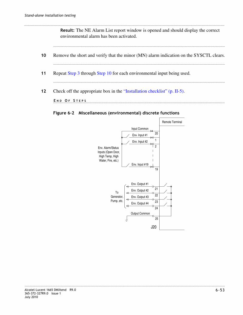
............................................................................................................................................................................................................................................................Alcatel-Lucent 1665 DMXtend R9.0365-372-327R9.0 Issue 1July 2010
6-53
............................................................................................................................................................................................................................................................
Stand-alone installation testing
Result: The NE Alarm List report window is opened and should display the correct environmental alarm has been activated.
........................................................................................................................................................................................................................
10 Remove the short and verify that the minor (MN) alarm indication on the SYSCTL clears.
........................................................................................................................................................................................................................
11 Repeat Step 3 through Step 10 for each environmental input being used.
........................................................................................................................................................................................................................
12 Check off the appropriate box in the “Installation checklist” (p. II-5).
........................................................................................................................................................E N D O F S T E P S
Figure 6-2 Miscellaneous (environmental) discrete functions
Env. Alarm/Status
Env. Input #19
Env. Input #2
Env. Input #1
2
1
20
Water, Fire, etc.)High Temp, High
Inputs (Open Door,
Remote Terminal
Input Common
19
Env. Output #3
Env. Output #2
Env. Output #1
Pump, etc.Generator,
25
24
23
22
21
Env. Output #4
J20
Output Common
To
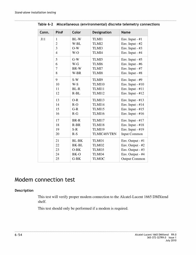
............................................................................................................................................................................................................................................................6-54 Alcatel-Lucent 1665 DMXtend R9.0
365-372-327R9.0 Issue 1July 2010
............................................................................................................................................................................................................................................................
Stand-alone installation testing
Table 6-2 Miscellaneous (environmental) discrete telemetry connections
Modem connection test
Description
This test will verify proper modem connection to the Alcatel-Lucent 1665 DMXtend shelf.
This test should only be performed if a modem is required.
Conn. Pin# Color Designation Name
J11 1234
BL-WW-BLO-WW-O
TLMI1TLMI2TLMI3TLMI4
Env. Input - #1Env. Input - #2Env. Input - #3Env. Input - #4
5678
G-WW-GBR-WW-BR
TLMI5TLMI6TLMI7TLMI8
Env. Input - #5Env. Input - #6Env. Input - #7Env. Input - #8
9101112
S-WW-SBL-RR-BL
TLMI9TLMI10TLMI11TLMI12
Env. Input - #9Env. Input - #10Env. Input - #11Env. Input - #12
13141516
O-RR-OG-RR-G
TLMI13TLMI14TLMI15TLMI16
Env. Input - #13Env. Input - #14Env. Input - #15Env. Input - #16
17181920
BR-RR-BRS-RR-S
TLMI17TLMI18TLMI19TLMIC48VTRN
Env. Input - #17Env. Input - #18Env. Input - #19Input Common
2122232425
BL-BKBK-BLO-BKBK-OG-BK
TLMO1TLMO2TLMO3TLMO4TLMOC
Env. Output - #1Env. Output - #2Env. Output - #3Env. Output - #4Output Common
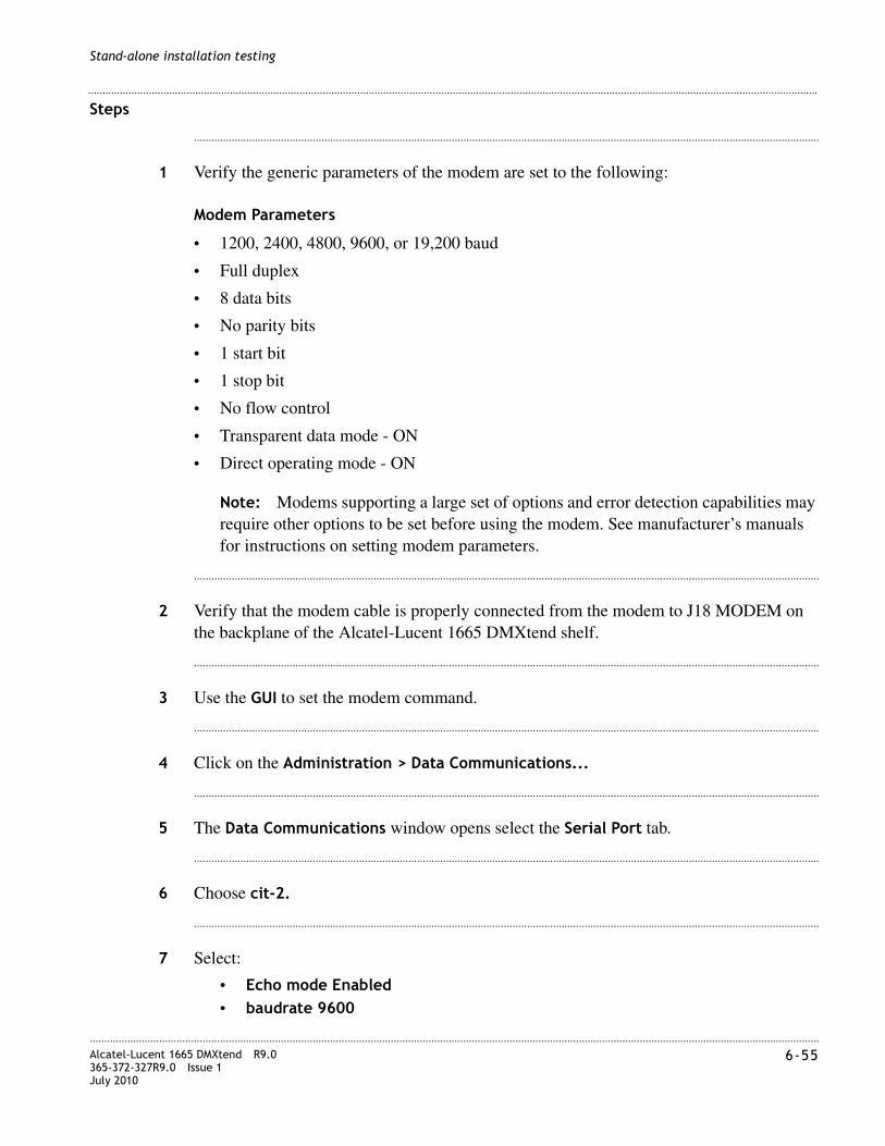
............................................................................................................................................................................................................................................................Alcatel-Lucent 1665 DMXtend R9.0365-372-327R9.0 Issue 1July 2010
6-55
............................................................................................................................................................................................................................................................
Stand-alone installation testing
Steps
........................................................................................................................................................................................................................
1 Verify the generic parameters of the modem are set to the following:
Modem Parameters
• 1200, 2400, 4800, 9600, or 19,200 baud
• Full duplex
• 8 data bits
• No parity bits
• 1 start bit
• 1 stop bit
• No flow control
• Transparent data mode - ON
• Direct operating mode - ON
Note: Modems supporting a large set of options and error detection capabilities may require other options to be set before using the modem. See manufacturer’s manuals for instructions on setting modem parameters.
........................................................................................................................................................................................................................
2 Verify that the modem cable is properly connected from the modem to J18 MODEM on the backplane of the Alcatel-Lucent 1665 DMXtend shelf.
........................................................................................................................................................................................................................
3 Use the GUI to set the modem command.
........................................................................................................................................................................................................................
4 Click on the Administration > Data Communications...
........................................................................................................................................................................................................................
5 The Data Communications window opens select the Serial Port tab.
........................................................................................................................................................................................................................
6 Choose cit-2.
........................................................................................................................................................................................................................
7 Select:
• Echo mode Enabled• baudrate 9600

............................................................................................................................................................................................................................................................6-56 Alcatel-Lucent 1665 DMXtend R9.0
365-372-327R9.0 Issue 1July 2010
............................................................................................................................................................................................................................................................
Stand-alone installation testing
• OSI Types TL1Test
........................................................................................................................................................................................................................
8 Click Apply to issue the command.
........................................................................................................................................................................................................................
9 Dial into the modem using an application such as HyperTerminal from a PC with a modem configured to similar parameters.
........................................................................................................................................................................................................................
10 After a connection is established, press the enter key.
Result: /* SYSTEM TID: LT-DMXTEND */
........................................................................................................................................................................................................................
11 Enter the command:
act-user:LT-DMXTEND:LUC01:ctag::DMXTND2.5G;
Result: A message indicating that the command completed will be displayed along with the Alcatel-Lucent disclosure.
........................................................................................................................................................................................................................
12 Enter the command:
canc-user:LT-DMXTEND:LUC01:ctag;
Result: A message indicating that the command completed will be displayed.
........................................................................................................................................................................................................................
13 Disconnect the HyperTerminal session.
........................................................................................................................................................................................................................
14 Check off the appropriate box in the “Installation checklist” (p. II-5).
........................................................................................................................................................E N D O F S T E P S
Final operations
Description
The following procedure ensures that all test signals and cross-connects have been removed and the Alcatel-Lucent 1665 DMXtend shelf is alarm free and ready for network connection procedures.
............................................................................................................................................................................................................................................................Alcatel-Lucent 1665 DMXtend R9.0365-372-327R9.0 Issue 1July 2010
6-57
............................................................................................................................................................................................................................................................
Stand-alone installation testing
Steps
........................................................................................................................................................................................................................
1 Use the GUI to View and Delete any cross-connects that were entered.
........................................................................................................................................................................................................................
2 Verify that no alarm LEDs are lit and no FAULT LED is lit on any circuit pack.
If any alarm is present, see Alcatel-Lucent 1665 Data Multiplexer Extend (DMXtend) User Operations Guide 365-372-325.
........................................................................................................................................................................................................................
3 If desired, reconnect the office alarm cable at this time.
........................................................................................................................................................................................................................
4 Check off the appropriate box in the “Installation checklist” (p. II-5).
........................................................................................................................................................E N D O F S T E P S

............................................................................................................................................................................................................................................................6-58 Alcatel-Lucent 1665 DMXtend R9.0
365-372-327R9.0 Issue 1July 2010
............................................................................................................................................................................................................................................................
Stand-alone installation testing

I I I-1Alcatel-Lucent 1665 DMXtend R9.0365-372-327R9.0 Issue 1July 2010
............................................................................................................................................................................................................................................................
Part III: Network turn-up and testing
Overview
Introduction
Part III covers fiber connections between nodes in a ring and used to verify WDMX connectivity between Alcatel-Lucent 1665 Data Multiplexer Extend (Alcatel-Lucent 1665 DMXtend) nodes. It is not intended to replace acceptance test procedures. If problems are encountered, see Alcatel-Lucent 1665 Data Multiplexer Extend (DMXtend) User Operations Guide 365-372-325 for detailed troubleshooting procedures.
Part III also provides the recommended checklist “Installation checklist” to follow when installing a Alcatel-Lucent 1665 Data Multiplexer Extend (Alcatel-Lucent 1665 DMXtend) system. Use of the installation checklist is required to ensure a quality installation. All completed tasks should be checked off and those not completed should be duly noted as to the reason why. This checklist should be turned in as part of your job complete paperwork.
Contents
This part includes the following chapters:
Tools, test equipment and accessories
This section lists the tools, test equipment and accessories needed to perform all the procedures in this installation manual.
Connecting adjacent network elements Chapter 7
WDMX setup and testing: integration procedures Chapter 8
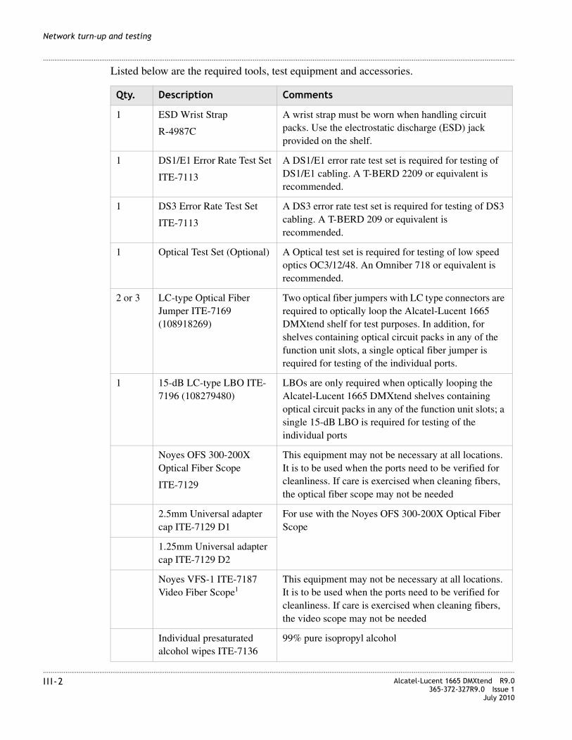
............................................................................................................................................................................................................................................................I I I-2 Alcatel-Lucent 1665 DMXtend R9.0
365-372-327R9.0 Issue 1July 2010
............................................................................................................................................................................................................................................................
Network turn-up and testing
Listed below are the required tools, test equipment and accessories.
Qty. Description Comments
1 ESD Wrist Strap
R-4987C
A wrist strap must be worn when handling circuit packs. Use the electrostatic discharge (ESD) jack provided on the shelf.
1 DS1/E1 Error Rate Test Set
ITE-7113
A DS1/E1 error rate test set is required for testing of DS1/E1 cabling. A T-BERD 2209 or equivalent is recommended.
1 DS3 Error Rate Test Set
ITE-7113
A DS3 error rate test set is required for testing of DS3 cabling. A T-BERD 209 or equivalent is recommended.
1 Optical Test Set (Optional) A Optical test set is required for testing of low speed optics OC3/12/48. An Omniber 718 or equivalent is recommended.
2 or 3 LC-type Optical Fiber Jumper ITE-7169 (108918269)
Two optical fiber jumpers with LC type connectors are required to optically loop the Alcatel-Lucent 1665 DMXtend shelf for test purposes. In addition, for shelves containing optical circuit packs in any of the function unit slots, a single optical fiber jumper is required for testing of the individual ports.
1 15-dB LC-type LBO ITE-7196 (108279480)
LBOs are only required when optically looping the Alcatel-Lucent 1665 DMXtend shelves containing optical circuit packs in any of the function unit slots; a single 15-dB LBO is required for testing of the individual ports
Noyes OFS 300-200X Optical Fiber Scope
ITE-7129
This equipment may not be necessary at all locations. It is to be used when the ports need to be verified for cleanliness. If care is exercised when cleaning fibers, the optical fiber scope may not be needed
2.5mm Universal adapter cap ITE-7129 D1
For use with the Noyes OFS 300-200X Optical Fiber Scope
1.25mm Universal adapter cap ITE-7129 D2
Noyes VFS-1 ITE-7187 Video Fiber Scope1
This equipment may not be necessary at all locations. It is to be used when the ports need to be verified for cleanliness. If care is exercised when cleaning fibers, the video scope may not be needed
Individual presaturated alcohol wipes ITE-7136
99% pure isopropyl alcohol

............................................................................................................................................................................................................................................................Alcatel-Lucent 1665 DMXtend R9.0365-372-327R9.0 Issue 1July 2010
I I I-3
............................................................................................................................................................................................................................................................
Network turn-up and testing
PC and cable requirements for WaveStar® CIT
This section lists the required equipment needed to run the WaveStar® CIT software with the Alcatel-Lucent 1665 DMXtend.
PC minimum requirements
For PC minimum requirements see “PC minimum requirements”.
1 CLETOP Cleaning Cassette ITE-7137
Type A Reel
1 CLETOP Cleaning Cassette Replacement Reel
ITE-7137 D1
Type A Reel
Luminex Stick port cleaners ITE-7134 & ITE-7135
1.25 mm and 2.5 mm sizes
Luminex Cloth R-6033 5.5” x 5.5”
Qty. Description Comments
Quantity Description Comments
1 Personal Computer (PC)
See PC minimum requirements below.
1 RS-232 Interface Cable
8-ft. long RJ45 to 9-pin D-sub serial cable (Comcode 848748869)
1 RJ45 to RJ45 Cross-over Cable

............................................................................................................................................................................................................................................................I I I-4 Alcatel-Lucent 1665 DMXtend R9.0
365-372-327R9.0 Issue 1July 2010
............................................................................................................................................................................................................................................................
Network turn-up and testing
Installation checklist
Section and chapter Procedure Required
Completed
Yes No
Part III: “Network turn-up and testing”
Chapter 7, “Connecting adjacent network elements”
“Fiber installation” (p. 7-3) Yes
“Optical transmission test (OC-192, OC-48, OC-12, OC-3)” (p. 7-10)
See Note 1
“Automatic protection switching test” (p. 7-11) See Note 1
“Manual switching tests” (p. 7-13)
“Final operations” (p. 7-15) Yes
Chapter 8, “WDMX setup and testing: integration procedures”
“Turn-up and test the LNW785 8-channel OMD” (p. 8-4)
See Note 1
“Turn up and test the LNW705 muxponder” (p. 8-6)
See Note 1
“Removing provisioning and equipage from the LNW785” (p. 8-16)
See Note 1
Notes: 1. Only required if equipped.
7-1Alcatel-Lucent 1665 DMXtend R9.0365-372-327R9.0 Issue 1July 2010
........................................................................................................................................................................
7 Connecting adjacent network elements
Overview
Purpose
This procedure is used to make fiber connections between nodes in a ring. It is not intended to replace acceptance test procedures. If problems are encountered, see Alcatel-Lucent 1665 Data Multiplexer Extend (DMXtend) User Operations Guide 365-372-325 for detailed troubleshooting procedures.
Contents
This chapter provides information on the following topics: Tools, Test Equipment and Accessories:
Fiber installation 7-3
Optical transmission test (OC-192, OC-48, OC-12, OC-3) 7-10
Automatic protection switching test 7-11
Manual switching tests 7-13
Final operations 7-15

........................................................................................................................................................................7-2 Alcatel-Lucent 1665 DMXtend R9.0
365-372-327R9.0 Issue 1July 2010
........................................................................................................................................................................
Connecting adjacent network elements
Listed below are the tools, test equipment and accessories necessary to perform the procedures in this section.
Quantity Description Comments
Screwdriver(s) A screwdriver(s) with the appropriate head(s) is (are) required for securing the mounting screws, repositioning the mounting brackets, installing the interfacing cables, and for setting the circuit breakers to the OFF position.
1 ESD Wrist Strap A wrist strap must be worn when handling circuit packs. Use the electrostatic discharge (ESD) jack provided on the shelf.
1 Multimeter (Optional) The voltmeter must be capable of measuring DC voltage in the 40 to 60 volt range. The use of the voltmeter is optional since the shelf will alarm or shut down if the proper voltage is not supplied.
1 DS1/E1 Error Rate Test Set A DS1/E1 error rate test set is required for testing of DS1/E1 cabling. A T-BERD 2209 or equivalent is recommended.
1 DS3 Error Rate Test Set A DS3 error rate test set is required for testing of DS3 cabling. A T-BERD 2209 or equivalent is recommended.
1 Personal Computer (PC)
1 CIT Interface Cable 8-ft. long RJ45 to 9-pin D-sub serial cable (Comcode 848748869).
1 Optical Power Meter
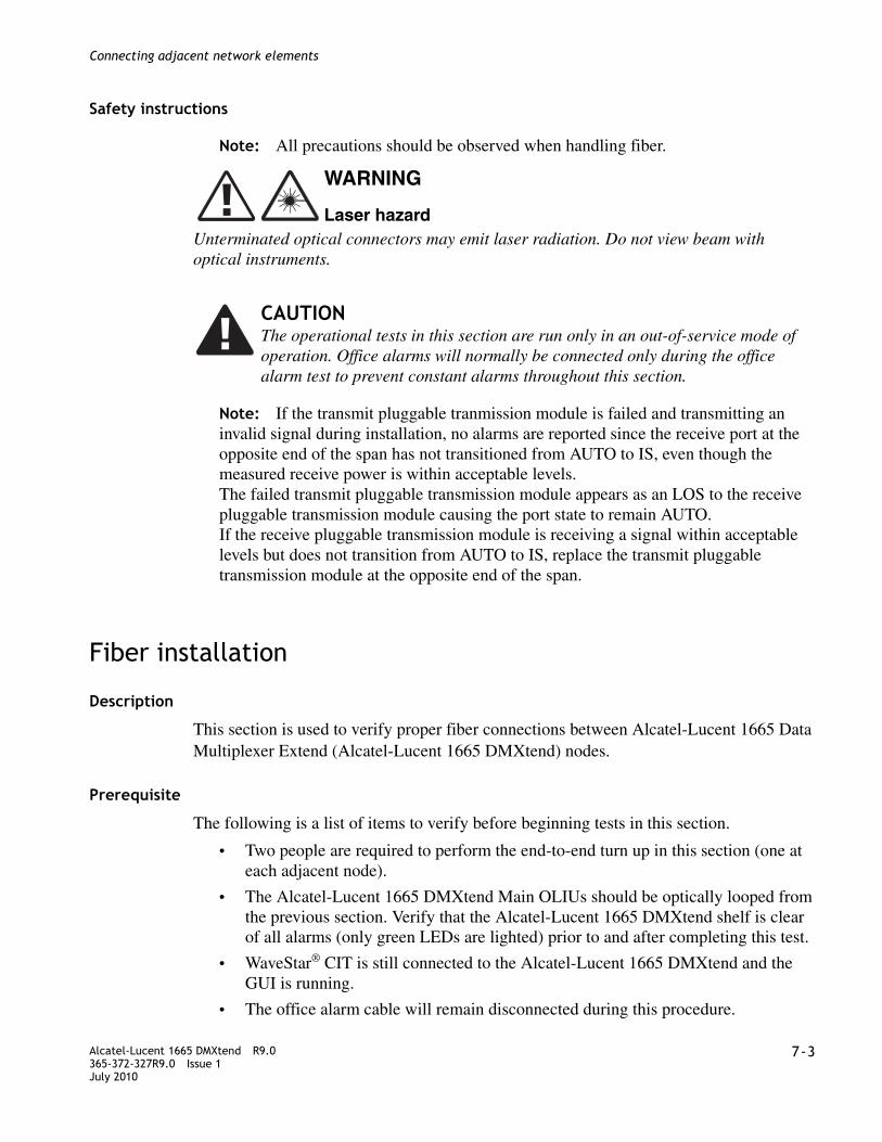
........................................................................................................................................................................Alcatel-Lucent 1665 DMXtend R9.0365-372-327R9.0 Issue 1July 2010
7-3
........................................................................................................................................................................
Connecting adjacent network elements
Safety instructions
Note: All precautions should be observed when handling fiber.
Unterminated optical connectors may emit laser radiation. Do not view beam with optical instruments.
Note: If the transmit pluggable tranmission module is failed and transmitting an invalid signal during installation, no alarms are reported since the receive port at the opposite end of the span has not transitioned from AUTO to IS, even though the measured receive power is within acceptable levels. The failed transmit pluggable transmission module appears as an LOS to the receive pluggable transmission module causing the port state to remain AUTO. If the receive pluggable transmission module is receiving a signal within acceptable levels but does not transition from AUTO to IS, replace the transmit pluggable transmission module at the opposite end of the span.
Fiber installation
Description
This section is used to verify proper fiber connections between Alcatel-Lucent 1665 Data Multiplexer Extend (Alcatel-Lucent 1665 DMXtend) nodes.
Prerequisite
The following is a list of items to verify before beginning tests in this section.
• Two people are required to perform the end-to-end turn up in this section (one at each adjacent node).
• The Alcatel-Lucent 1665 DMXtend Main OLIUs should be optically looped from the previous section. Verify that the Alcatel-Lucent 1665 DMXtend shelf is clear of all alarms (only green LEDs are lighted) prior to and after completing this test.
• WaveStar® CIT is still connected to the Alcatel-Lucent 1665 DMXtend and the GUI is running.
• The office alarm cable will remain disconnected during this procedure.
WARNING
Laser hazard
CAUTIONThe operational tests in this section are run only in an out-of-service mode of operation. Office alarms will normally be connected only during the office alarm test to prevent constant alarms throughout this section.

........................................................................................................................................................................7-4 Alcatel-Lucent 1665 DMXtend R9.0
365-372-327R9.0 Issue 1July 2010
........................................................................................................................................................................
Connecting adjacent network elements
• A properly grounded ESD wrist strap must always be worn while handling circuit packs.
A properly grounded ESD wrist strap MUST be worn when handling circuit packs.
Unterminated optical connectors may emit laser radiation. Do not view beam with optical instruments.
Steps
The following procedures are performed at each end of the optical span being tested.
................................................................................................................................................
1 Verify that the office alarm cable to J13 (ALM) on the backplane of the Alcatel-Lucent 1665 DMXtend shelf is disconnected. If the shelf to be tested is part of a multiple shelf bay arrangement, the office alarm cable connects to shelf 1.
................................................................................................................................................
2 Enter the shelf TID per the customer order or use LT-DMXTEND-1 and LT-DMXTEND-2 as defaults.
................................................................................................................................................
3 Use the Graphical User Interface (GUI) to enable the AGNE at LT-DMXTEND-1 only.
................................................................................................................................................
4 Click on Administration > Set NE...
................................................................................................................................................
5 In the Set NE window click on:
• Remote NE Status: Enabled• AGNE: Enabled
................................................................................................................................................
6 Use the GUI to enable the Remote NE Status at all nodes.
................................................................................................................................................
7 In the GUI screen for each NE click on Administration > Set NE...
CAUTION
ESD hazard
WARNING
Laser hazard
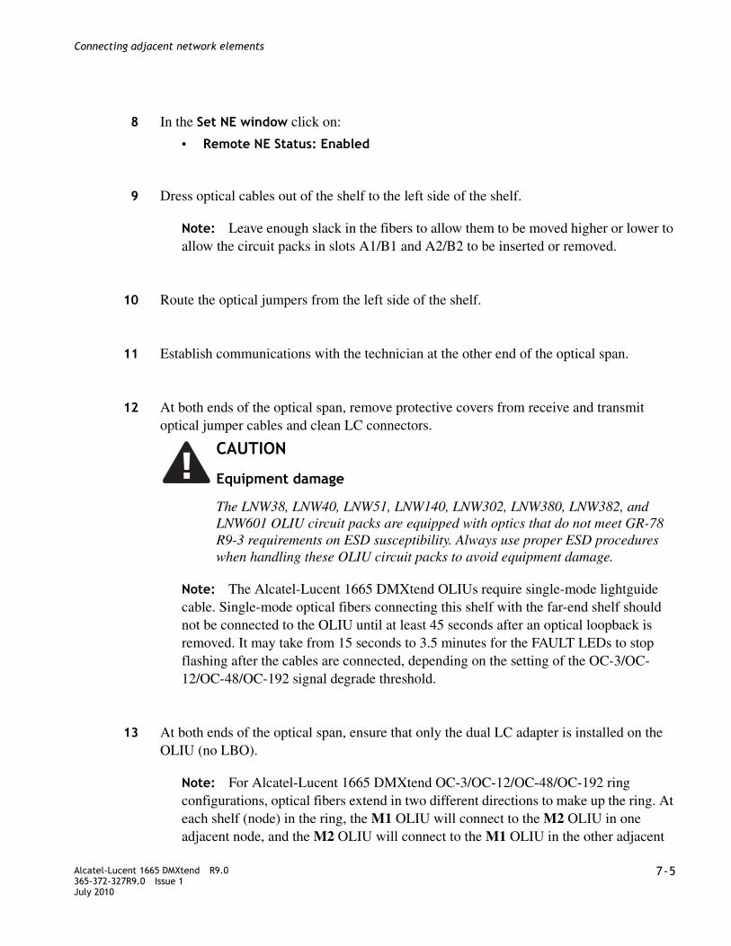
........................................................................................................................................................................Alcatel-Lucent 1665 DMXtend R9.0365-372-327R9.0 Issue 1July 2010
7-5
........................................................................................................................................................................
Connecting adjacent network elements
................................................................................................................................................
8 In the Set NE window click on:
• Remote NE Status: Enabled
................................................................................................................................................
9 Dress optical cables out of the shelf to the left side of the shelf.
Note: Leave enough slack in the fibers to allow them to be moved higher or lower to allow the circuit packs in slots A1/B1 and A2/B2 to be inserted or removed.
................................................................................................................................................
10 Route the optical jumpers from the left side of the shelf.
................................................................................................................................................
11 Establish communications with the technician at the other end of the optical span.
................................................................................................................................................
12 At both ends of the optical span, remove protective covers from receive and transmit optical jumper cables and clean LC connectors.
Note: The Alcatel-Lucent 1665 DMXtend OLIUs require single-mode lightguide cable. Single-mode optical fibers connecting this shelf with the far-end shelf should not be connected to the OLIU until at least 45 seconds after an optical loopback is removed. It may take from 15 seconds to 3.5 minutes for the FAULT LEDs to stop flashing after the cables are connected, depending on the setting of the OC-3/OC-12/OC-48/OC-192 signal degrade threshold.
................................................................................................................................................
13 At both ends of the optical span, ensure that only the dual LC adapter is installed on the OLIU (no LBO).
Note: For Alcatel-Lucent 1665 DMXtend OC-3/OC-12/OC-48/OC-192 ring configurations, optical fibers extend in two different directions to make up the ring. At each shelf (node) in the ring, the M1 OLIU will connect to the M2 OLIU in one adjacent node, and the M2 OLIU will connect to the M1 OLIU in the other adjacent
CAUTION
Equipment damage
The LNW38, LNW40, LNW51, LNW140, LNW302, LNW380, LNW382, and LNW601 OLIU circuit packs are equipped with optics that do not meet GR-78 R9-3 requirements on ESD susceptibility. Always use proper ESD procedures when handling these OLIU circuit packs to avoid equipment damage.

........................................................................................................................................................................7-6 Alcatel-Lucent 1665 DMXtend R9.0
365-372-327R9.0 Issue 1July 2010
........................................................................................................................................................................
Connecting adjacent network elements
node. Likewise, when the Alcatel-Lucent 1665 DMXtend is interfacing with other equipment at low-speeds (OC-3, OC-12 or OC-48) using 0x1 protection, the Function Group slot (D, or G) 1 will connect to Main 2 on whatever shelf the Alcatel-Lucent 1665 DMXtend is being connected to. The Function Group slot (D, or G) 2 will connect to Main 1.
................................................................................................................................................
14 At each end of the optical span, connect the optical fiber transmit cables to the OLIU OUT connectors.
................................................................................................................................................
15 At each end of the optical span, measure the optical power of the optical fiber receive cables using an optical power meter.
................................................................................................................................................
16 Determine the LBO value required based on the received optical power measurement. See the following table and attenuate appropriately.
Table 7-1 Attenuation table
Optics Circuit packReceived power (dBM)
LBO (dB)
OC-3 (high speed)
LNW40 -8.0 to -28.0 0
LNW140 -8.0 to -28.0 0
LNW601 0.0 to -15.0 10
LNW302 TBD 0
Low-speed optics (OC-48)
LNW31 (OC-48) 0.0 to -18.0 0
OC-12 (high speed)
LNW38 -8.0 to -28.0 0
LNW51 -8.0 to -30.5 0
LNW380 -8.0 to -29.0 0
LNW382 TBD 0
OC-48 PTM (pluggable transmission module) optics
LNW41/55/62 LR-1 Optics -9.0 to -27.0 10
LNW41/55/62 LR-2 Optics -9.0 to -28.0 10
LNW41/55/62 SR-1 Optics -3.0 to -18.0 5
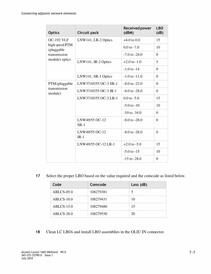
........................................................................................................................................................................Alcatel-Lucent 1665 DMXtend R9.0365-372-327R9.0 Issue 1July 2010
7-7
........................................................................................................................................................................
Connecting adjacent network elements
................................................................................................................................................
17 Select the proper LBO based on the value required and the comcode as listed below.
................................................................................................................................................
18 Clean LC LBOs and install LBO assemblies in the OLIU IN connector.
OC-192 VLF high speed PTM (pluggable transmission module) optics
LNW141, LR-2 Optics +4.0 to 0.0 15
0.0 to -7.0 10
-7.0 to -24.0 0
LNW141, IR-2 Optics +2.0 to -1.0 5
-1.0 to -14 0
LNW141, SR-1 Optics -1.0 to -11.0 0
PTM (pluggable transmission module)
LNW37/45/55 OC-3 SR-1 -8.0 to -23.0 0
LNW37/45/55 OC-3 IR-1 -8.0 to -28.0 0
LNW37/45/55 OC-3 LR-1 0.0 to -5.0 15
-5.0 to -10 10
-10 to -34.0 0
LNW49/55 OC-12 SR-1
-8.0 to -28.0 0
LNW49/55 OC-12 IR-1
-8.0 to -28.0 0
LNW49/55 OC-12 LR-1 +2.0 to -5.0 15
-5.0 to -15 10
-15 to -28.0 0
Optics Circuit packReceived power (dBM)
LBO (dB)
Code Comcode Loss (dB)
ABLCS-05.0 108279381 5
ABLCS-10.0 108279431 10
ABLCS-15.0 108279480 15
ABLCS-20.0 108279530 20

........................................................................................................................................................................7-8 Alcatel-Lucent 1665 DMXtend R9.0
365-372-327R9.0 Issue 1July 2010
........................................................................................................................................................................
Connecting adjacent network elements
................................................................................................................................................
19 At the far end, connect the input optical fiber to the proper OLIU IN connector.
Result: The FAULT LED on the OLIU extinguishes.
................................................................................................................................................
20 At the near end, connect the input optical fiber to the proper OLIU IN connector.
Result: The FAULT LED on the OLIU extinguishes.
................................................................................................................................................
21 Disconnect the fiber cable from the OUT connector on the OLIU at one end of the span. At the other end, verify that the associated FAULT LED is flashing, indicating a loss of signal. Reconnect the fiber and repeat the process for the other direction of transmission.
................................................................................................................................................
22 In order to enable communications with the adjacent Alcatel-Lucent 1665 DMXtend nodes,
................................................................................................................................................
23 Use the GUI to turn off the DCCs. Configuration > DCC Terminations
................................................................................................................................................
24 The Configure DCC Terminations window will be displayed.
................................................................................................................................................
25 For Port AID: select dcc-m1-1
................................................................................................................................................
26 For OSI Over DCC select enabled.
................................................................................................................................................
27 For LAPD Roll: select user-side.
................................................................................................................................................
28 Click Apply to send the command.
................................................................................................................................................
29 For Port AID: select dcc-m2-1.
................................................................................................................................................
30 For OSI Over DCC select enabled.

........................................................................................................................................................................Alcatel-Lucent 1665 DMXtend R9.0365-372-327R9.0 Issue 1July 2010
7-9
........................................................................................................................................................................
Connecting adjacent network elements
................................................................................................................................................
31 For LAPD Roll: select Network-side.
................................................................................................................................................
32 Click Apply to send the command.
................................................................................................................................................
33 Set the timing to Free Running at LT-DMXTEND-1 and Line LT-DMXTEND-2.
................................................................................................................................................
34 Use the GUI to change the system timing. Configuration > Timing Sync
................................................................................................................................................
35 The Configure Timing/Sync window will be displayed.
................................................................................................................................................
36 Under the System Timing tab set the Timing Mode: to Free Running at LT-DMXTEND-1 and to Line at LT-DMXTEND-2.
................................................................................................................................................
37 Click OK to issue the command.
................................................................................................................................................
38 In order to verify proper communications with the adjacent Alcatel-Lucent 1665 DMXtend nodes, execute the following command from the GUI.Administration > OSI-Neighbor-Map
Result: The TIDs and NSAPs of adjacent nodes will be displayed along with the OLIU and port they are connected to.
................................................................................................................................................
39 In order to verify proper network DCC communications, execute the following command from the GUI.Administration > OSI-Routing-Map
Result: The TIDs and NSAPs of all the nodes in the TARP area will be displayed.
................................................................................................................................................
40 Perform steps in this procedure on all adjacent nodes in the ring.

........................................................................................................................................................................7-10 Alcatel-Lucent 1665 DMXtend R9.0
365-372-327R9.0 Issue 1July 2010
........................................................................................................................................................................
Connecting adjacent network elements
................................................................................................................................................
41 After all connections and tests have been made, verify optical fiber cables are placed in the fiber slots on the left side of the shelf and properly routed in bay framework.
................................................................................................................................................
42 Check off the appropriate box in the “Installation checklist” (p. III-4).
........................................................................................................................................................E N D O F S T E P S
Optical transmission test (OC-192, OC-48, OC-12, OC-3)
Steps
................................................................................................................................................
1 Use the GUI command: Performance > Initialize PM Registers.
................................................................................................................................................
2 Click on the Both.
................................................................................................................................................
3 Click Yes to execution command.
................................................................................................................................................
4 Wait 15 minutes.
................................................................................................................................................
5 At the test location, enter the following GUI command:Performance > View PM/Statistics Reports > OCn Line
................................................................................................................................................
6 Double-click CP main-1.
................................................................................................................................................
7 Select Port 1 (OC3).
................................................................................................................................................
8 For Time Period select 1 Day.
................................................................................................................................................
9 For Monitored Date, select Current Date.

........................................................................................................................................................................Alcatel-Lucent 1665 DMXtend R9.0365-372-327R9.0 Issue 1July 2010
7-11
........................................................................................................................................................................
Connecting adjacent network elements
................................................................................................................................................
10 For Monitor Level Select 0-UP.
................................................................................................................................................
11 Under the Near End tab click on the Select All button.
................................................................................................................................................
12 Click Apply.
Result: The OCn Line PM Report window indicates no transmission errors.
................................................................................................................................................
13 Repeat Step 1 through Step 12 for all Alcatel-Lucent 1665 DMXtend shelves at the test location.
................................................................................................................................................
14 Repeat Step 1 through Step 12 for each node in the ring.
................................................................................................................................................
15 Check off the appropriate box in the “Installation checklist” (p. III-4).
........................................................................................................................................................E N D O F S T E P S
Automatic protection switching test
Description
This section provides the procedures for verifying the Alcatel-Lucent 1665 DMXtend shelf automatic and manual protection switching.
Note the following:
• These tests do NOT simulate circuit pack failures.
• A properly grounded wrist strap must always be worn while handling circuit packs.
• Prior to performing each test, the shelf under test must be clear of all alarms (that is, only green LEDs are lighted).

........................................................................................................................................................................7-12 Alcatel-Lucent 1665 DMXtend R9.0
365-372-327R9.0 Issue 1July 2010
........................................................................................................................................................................
Connecting adjacent network elements
Main OLIU switch test
................................................................................................................................................
1 In order to perform path switching, enter an STS-1 add/drop cross-connection between an equipped Function Unit and the Main OLIU. Select Configuration > Cross-Connections... and use the Cross-Connection Wizard to enter an add/drop cross-connection.
................................................................................................................................................
2 Select View > Protection...
................................................................................................................................................
3 Under Path Protection choose Path m1-1-1 and click Select.
................................................................................................................................................
4 Note the Active Path (m1 or m2).
................................................................................................................................................
5 Disconnect the optical fiber connected to the IN port on the active path OLIU.
Result: The MN and then MJ alarm LED should light on the SYSCTL and the FAULT LED should flash on the OLIU.
................................................................................................................................................
6 Click Refresh in the View Protection window.
................................................................................................................................................
7 Verify the Active Path has changed (from m1 to m2 or m2 to m1).
................................................................................................................................................
8 Reconnect the optical fiber to the OLIU.
Result: After a short time, the MJ alarm LED on the SYSCTL and the FAULT LED on the OLIU should extinguish.
................................................................................................................................................
9 Repeat Step 2 through Step 8 to verify a switch back to the OLIU that was originally active.
................................................................................................................................................
10 Check off the appropriate box in the “Installation checklist” (p. III-4).
........................................................................................................................................................E N D O F S T E P S

........................................................................................................................................................................Alcatel-Lucent 1665 DMXtend R9.0365-372-327R9.0 Issue 1July 2010
7-13
........................................................................................................................................................................
Connecting adjacent network elements
Manual switching tests
Description
This test will initiate switching commands from the CIT and verify proper switching and LED indications.
Note: An STS-1 cross-connect is required in order to perform manual switching.
Manual switching test procedure
................................................................................................................................................
1 Enter an STS-1 add/drop cross-connection between an equipped Function Unit and the Main OLIU. Select Configuration > Cross-Connections... and use the Cross-Connection Wizard to enter an add/drop cross-connection.
................................................................................................................................................
2 Select Fault > Protection Switch...
................................................................................................................................................
3 Under Path Protection choose Path m1-1-1 and click Select.
................................................................................................................................................
4 Note the Active Path (m1 or m2).
................................................................................................................................................
5 Choose Switch Type: Manual.
................................................................................................................................................
6 Click Apply.
................................................................................................................................................
7 Verify that the Active Path: has changed (m1 to m2 or m2 to m1).
................................................................................................................................................
8 Repeat Step 2 through Step 7 to verify a switch back to the original ring.
................................................................................................................................................
9 Check off the appropriate box in the “Installation checklist” (p. III-4).
........................................................................................................................................................E N D O F S T E P S

........................................................................................................................................................................7-14 Alcatel-Lucent 1665 DMXtend R9.0
365-372-327R9.0 Issue 1July 2010
........................................................................................................................................................................
Connecting adjacent network elements
Function units/growth slots switching test
This test will initiate switching commands from the CIT and verify proper switching and LED indications.
Note: This procedure should be performed on each function unit equipped with protected electrical TDM circuit packs.
................................................................................................................................................
1 Select Fault > Protection Switch...
................................................................................................................................................
2 Click on 1+1 Equip fn-x (x is a, b, d or g corresponding to the function group equipped).
................................................................................................................................................
3 Click Select.
................................................................................................................................................
4 Note which function unit or growth slot circuit pack is the active circuit pack.
................................................................................................................................................
5 In the Switch Type: pull-down, select Manual (Normal).
................................................................................................................................................
6 Click Apply.
Result: The pack that was active should now be the standby pack and the pack that was standby is now active. Transmission should take a momentary hit as it is switched to the other pack. This information should agree with the ACTIVE LEDs on the circuit packs.
................................................................................................................................................
7 Repeat Step 1 through Step 6 to verify a switch back to the original function unit circuit pack, with the same results as the previous step.
................................................................................................................................................
8 Repeat this procedure for each function unit pair.
................................................................................................................................................
9 Swap circuit packs from another function group to test any unequipped function slots.
........................................................................................................................................................................Alcatel-Lucent 1665 DMXtend R9.0365-372-327R9.0 Issue 1July 2010
7-15
........................................................................................................................................................................
Connecting adjacent network elements
................................................................................................................................................
10 Check off the appropriate box in the “Installation checklist” (p. III-4).
........................................................................................................................................................E N D O F S T E P S
Final operations
Description
The following procedure ensures that all test signals and cross-connects have been removed and the Alcatel-Lucent 1665 DMXtend shelf is alarm free and ready for network connection procedures.
Steps
................................................................................................................................................
1 Use the GUI command: View > Cross-Connections
................................................................................................................................................
2 Click the Shelf (Alcatel-Lucent 1665 DMXtend).
................................................................................................................................................
3 Click Select to send the command.
Result: The View Cross-Connections Window should display the cross-connect entered earlier.
................................................................................................................................................
4 Use the GUI command Configuration > Cross-Connections.
................................................................................................................................................
5 In the Cross-Connection Wizard click on the Delete (legs) of an existing cross-connect.
................................................................................................................................................
6 Click Next.
................................................................................................................................................
7 Select Shelf (Alcatel-Lucent 1665 DMXtend).

........................................................................................................................................................................7-16 Alcatel-Lucent 1665 DMXtend R9.0
365-372-327R9.0 Issue 1July 2010
........................................................................................................................................................................
Connecting adjacent network elements
................................................................................................................................................
8 Double click CP main-1.
................................................................................................................................................
9 Select Port 1 (OCn).
................................................................................................................................................
10 Highlight the Cross-Connect shown.
................................................................................................................................................
11 Select Next.
................................................................................................................................................
12 Select Next.
................................................................................................................................................
13 Select Finish.
................................................................................................................................................
14 Select Yes to the execution warning message.
................................................................................................................................................
15 Repeat Step 1 through Step 14 to verify no further cross-connects exist.
................................................................................................................................................
16 Verify that no alarm LEDs are lit and no FAULT LED is lit on any circuit pack.
If any alarm is present, see Alcatel-Lucent 1665 Data Multiplexer Extend (DMXtend) User Operations Guide 365-372-325.
........................................................................................................................................................E N D O F S T E P S
Clear PM registers
The following steps will clear all the performance monitoring registers:
................................................................................................................................................
1 Use the GUI command. Performance > Initialize PM Registers > 15-Min
................................................................................................................................................
2 Click Yes to execution command.

........................................................................................................................................................................Alcatel-Lucent 1665 DMXtend R9.0365-372-327R9.0 Issue 1July 2010
7-17
........................................................................................................................................................................
Connecting adjacent network elements
................................................................................................................................................
3 Reconnect the office alarm cable at this time.
................................................................................................................................................
4 Check off the appropriate box in the “Installation checklist” (p. III-4).
........................................................................................................................................................E N D O F S T E P S

........................................................................................................................................................................7-18 Alcatel-Lucent 1665 DMXtend R9.0
365-372-327R9.0 Issue 1July 2010
........................................................................................................................................................................
Connecting adjacent network elements
8-1Alcatel-Lucent 1665 DMXtend R9.0365-372-327R9.0 Issue 1July 2010
........................................................................................................................................................................
8 WDMX setup and testing: integration procedures
Overview
Purpose
This chapter is used to verify WDMX connectivity between Alcatel-Lucent 1665 Data Multiplexer Extend (Alcatel-Lucent 1665 DMXtend) nodes. The chapter includes the LNW785 8 channel Optical Multiplexer Demultiplexer (OMD) circuit pack. It is not intended to replace acceptance test procedures.
The testing performed in this procedure uses an OC-48 test set. If the OC48 PTM and test sets are unavailable, other rates or signals can be substituted, i.e OC-3/-12 or GigE. If additional provisioning procedures are desired, see Alcatel-Lucent 1665 Data Multiplexer Extend (DMXtend) User Operations Guide 365-372-325. For detailed troubleshooting procedures, see Alcatel-Lucent 1665 Data Multiplexer Extend (DMXtend) Maintenance and Trouble Clearing Guide 365-372-326.
Contents
This chapter provides information on the following topics
Turn up and test the LNW705 muxponder 8-4
Turn up and test the LNW705 muxponder 8-6
Integrating the LNW705 into the LNW785 8-9
Removing provisioning and equipage from the LNW705 and LNW785 8-11
Connecting the ring (Mains) to the WDMX 8-14
Removing provisioning and equipage from the LNW785 8-16

........................................................................................................................................................................8-2 Alcatel-Lucent 1665 DMXtend R9.0
365-372-327R9.0 Issue 1July 2010
........................................................................................................................................................................
WDMX setup and testing: integration procedures
How to use this chapter
All of the sections in this chapter are stand alone procedures and are not intended to be followed in any sequence. Locate the procedure in this chapter and follow the procedure based on the requirements of the turn-up. When one procedure relies on steps from another procedure or continues on with the next procedure, the link is provided in the procedure.
Tools, test equipment and accessories
Listed below are the tools, test equipment and accessories necessary to perform the procedures in this section.
Prerequisite
The following is a list of items to verify before beginning tests in this section.
• Two or more people are required to perform the end-to-end turn up in this section (one at each adjacent node).
• The office alarm cable will remain disconnected during this procedure.
Safety instructions
Note: All precautions should be observed when handling fiber.
Quantity Description Comments
1 ESD Wrist Strap A wrist strap must be worn when handling circuit packs. Use the electrostatic discharge (ESD) jack provided on the shelf.
1 OC-48 Test Set An OC-48 test set is required for testing of optical circuit packs. An Agilent OmniBER 718 or equivalent is recommended.
1 Personal Computer (PC)
1 CIT Interface Cable 8-ft. long RJ45 to 9-pin D-sub serial cable (Comcode 848748869).
1 Optical Power Meter

........................................................................................................................................................................Alcatel-Lucent 1665 DMXtend R9.0365-372-327R9.0 Issue 1July 2010
8-3
........................................................................................................................................................................
WDMX setup and testing: integration procedures
Unterminated optical connectors may emit laser radiation. Do not view beam with optical instruments.
A properly grounded ESD wrist strap MUST be worn when handling circuit packs.
Unterminated optical connectors may emit laser radiation. Do not view beam with optical instruments.
WARNING
Laser hazard
CAUTIONThe operational tests in this section are run only in an out-of-service mode of operation. Office alarms will normally be connected only during the office alarm test to prevent constant alarms throughout this section.
CAUTION
ESD hazard
WARNING
Laser hazard
CAUTION
Laser Safety
When connecting fiber loops between the IN and OUT ports on optical circuit packs, always connect to the IN port first and then the OUT port. This will prevent any optical radiation from being present at the fiber end.

........................................................................................................................................................................8-4 Alcatel-Lucent 1665 DMXtend R9.0
365-372-327R9.0 Issue 1July 2010
........................................................................................................................................................................
WDMX setup and testing: integration procedures
Turn-up and test the LNW785 8-channel OMD
Description
This procedure provides a method to provision and test an optical span using the 8-channel OMD LNW785 circuit pack. The procedure requires a LNW785 at both ends of the span and that there is least one OC-192/10Gbps source at each end of the span. The source OC-192 could be a LNW141 or an OC-192/10Gbps from a alien shelf but the source MUST be compatible with the wavelengths on the LNW785. The LNW141 must be equipped with X10G52C5, X10G53C5, X10G54C5, or X10G55C5. If using an alien 10Gbps source, see Table 8-3, “Channel/port assignments” (p. 8-19) for the wavelengths specifications.
................................................................................................................................................
1 Determine and document the test signal frequency.
................................................................................................................................................
2 Install the LNW785 into the Alcatel-Lucent 1665 DMXtend shelf by opening both faceplate latches and seating in the slot while closing the latches.
Note: The LNW785 can be installed in any Function/Growth slot. When the shelf is to be configured as an add/drop, it is recommended that the Growth slots are not used because the passthrough fibers would have to route over the SYSCTL. If the Main slots are not equipped with Very Large Fabric LNW141 or LNW84 OLIU circuit packs, then the circuit packs in a Function/Growth slot must be the same type.
................................................................................................................................................
3 Login to the Alcatel-Lucent 1665 DMXtend using the WaveStar® CIT.
................................................................................................................................................
4 Create OCH Cross-connectionsSelect Configuration > OCH Cross-connections from the System View
................................................................................................................................................
5 Select the Create a new OCH cross-connection radio button in the OCH Cross-Connection Wizard. Click Next.Click the 2-way Add/Drop radio button from the cross-connection list. Click Next.
................................................................................................................................................
6 Click Select, then select REMAID and the port will appear on the right side of the screen, click on the Port to highlight it then click Select.

........................................................................................................................................................................Alcatel-Lucent 1665 DMXtend R9.0365-372-327R9.0 Issue 1July 2010
8-5
........................................................................................................................................................................
WDMX setup and testing: integration procedures
................................................................................................................................................
7 Click Select for the Add/Drop port, expand the circuit pack (OMD5/8) and click on the Port and the port will appear on the right side of the screen, click on the Port to highlight it then click Select.
Note: The port is determined by the test signal wavelength documented in Step .
................................................................................................................................................
8 Click Next, then Finish and complete the cross-connection by clicking on Yes in the confirmation window.
................................................................................................................................................
9 Connect fibers from Test port to selected channel on LNW785, while observing optical power requirements and cleaning procedures.
................................................................................................................................................
10 Repeat Step 2 to Step 9 at the remote Network Element.
................................................................................................................................................
11 Connect the Transmit fibers on the LNW785 at each end, following proper fiber cleaning procedures.
................................................................................................................................................
12 Connect the Receive fibers on the LNW785 at each end, while observing optical power requirements and cleaning procedures.
Result: Span is in-service
................................................................................................................................................
13 If adding a span in the other direction using the LNW785 repeat Step 2 through Step 12, otherwise continue.
................................................................................................................................................
14 Perform end-to-end testing. Follow the end to end testing procedures determined by the input test signal. If the test signal is the Alcatel-Lucent 1665 DMXtend as part of a ring, proceed to Chapter 8, “WDMX setup and testing: integration procedures” and locate the appropriate procedure
................................................................................................................................................
15 Check off the appropriate box in the “Installation checklist” (p. III-4).

........................................................................................................................................................................8-6 Alcatel-Lucent 1665 DMXtend R9.0
365-372-327R9.0 Issue 1July 2010
........................................................................................................................................................................
WDMX setup and testing: integration procedures
Turn up and test the LNW705 muxponder
Description
The following procedure is a simple method of testing end to end continuity of the LNW705 Muxponder circuit. The test requires that a LNW705 is installed in two nodes and that there is fiber continuity between the two LNW705s. The fiber path could be a direct fiber connection, through a passive optics device, a LNW785 or through another DWDM system. In any case, the LNW705 link must be established. Once the end-to-end link has been established, an OC-3/OC-12/OC-48 test set and PTMs will be used to perform the end to end test.
Steps
This procedure provides the steps needed to equip and test an Alcatel-Lucent 1665 DMXtend with one LNW705 in G2. The steps include installing and equipping the LNW705 with the 10G and low speed PTMs, along with all the necessary provisioning.
................................................................................................................................................
1 Install the LNW705 into the Alcatel-Lucent 1665 DMXtend shelf by opening both faceplate latches and seating in the slot while closing the latches.
Note: The LNW705 can only be installed in Growth 2 slot.
................................................................................................................................................
2 Install the appropriate 10G PTM Table 8-3, “Channel/port assignments” (p. 8-19) into Port 9.
................................................................................................................................................
3 Install an OC-3/OC-12/OC-48 PTM in Port 1 of the LNW705 [see Appendix E, “Pluggable transmission modules (PTM)” (p. E-1)].
Note: The PTMs at both ends of the circuit must be the same rate.
For purposes of this document, the examples in the procedures below are equipped with an OC-48 PTM. Other signals listed in Appendix E, “Pluggable transmission modules (PTM)” (p. E-1) could be substituted, however use the guidelines set in “LNW705 XM10G/8 port guidelines” (p. 9-18) for the port restrictions.
................................................................................................................................................
4 Login to the Alcatel-Lucent 1665 DMXtend using the WaveStar® CIT.

........................................................................................................................................................................Alcatel-Lucent 1665 DMXtend R9.0365-372-327R9.0 Issue 1July 2010
8-7
........................................................................................................................................................................
WDMX setup and testing: integration procedures
................................................................................................................................................
5 Provision the PTM/OTU-2Select Configuration > Equipment from the System View
................................................................................................................................................
6 Click the “+” next to XM10G/8 circuit pack to expand the list.
................................................................................................................................................
7 Highlight the PTM sc9 and click Select.
................................................................................................................................................
8 Enter the Frequency in the Expected Frequency and click Apply.
Note: The frequency is determined by the PTM inserted in Port 9. See the LNW705 column in Table 8-3, “Channel/port assignments” (p. 8-19) for acceptable values.
................................................................................................................................................
9 Highlight the Port 1 and click Select.
................................................................................................................................................
10 Set the Signal type to match the PTM type, using the pull down window (for example if the PTM is a OC48SR1-I1, set the Signal Type to OC48) and click Apply.
................................................................................................................................................
11 Perform a single node self test by connecting an OC-48 test set to Port 1, while observing the proper optical power levels and cleaning procedures.Insert a 15 dB LBO into the input of Port 9 and connect a fiber from the output of Port 9 to the input of Port 9.
................................................................................................................................................
12 Connect an OC-48 test set to the PTM in port 1 while observing the proper optical power levels listed in Table 8-4, “Attenuation Table” (p. 8-19).
................................................................................................................................................
13 Condition the test set to transmit and receive a STS-48 PRBS test signal.
Result: Observe error-Free Transmission.
................................................................................................................................................
14 Inject a single error from the test set.
Result: Test set reports the error.

........................................................................................................................................................................8-8 Alcatel-Lucent 1665 DMXtend R9.0
365-372-327R9.0 Issue 1July 2010
........................................................................................................................................................................
WDMX setup and testing: integration procedures
................................................................................................................................................
15 Repeat Step 1 to Step 14 at the other node.
................................................................................................................................................
16 Remove fiber and LBOs from Port 9 of both LNW705s.
................................................................................................................................................
17 Establish the end to end link on the 10G PTM while observing the proper optical levels listed in Table 8-4, “Attenuation Table” (p. 8-19). If connecting through the LNW785 go to “Integrating the LNW705 into the LNW785” (p. 8-9), otherwise continue.
................................................................................................................................................
18 Locate and connect the span fibers to the LNW705 while observing the proper optical levels listed in Table 8-4, “Attenuation Table” (p. 8-19).
................................................................................................................................................
19 Repeat Step 18 at the LNW705 at the other node on the opposite end of the span.
................................................................................................................................................
20 Observe test set and verify error-free transmission. If only one test set is available, connect a fiber from the In port to the Out port of the PTM in port 1 at one end. Use the information listed in Table 8-4, “Attenuation Table” (p. 8-19) to determine the proper LBO/Attenuator.
Note: Test duration may be determined by engineering specification or by the end customer.
................................................................................................................................................
21 Disconnect test set(s) and fiber jumper from ports.
................................................................................................................................................
22 Remove PTM from LNW705 if necessary and clear any associated alarms by selectingConfiguration > Update System> Update Inventory.
................................................................................................................................................
23 Check off the appropriate box in Table I-3, Installation acceptance checklist.
........................................................................................................................................................E N D O F S T E P S
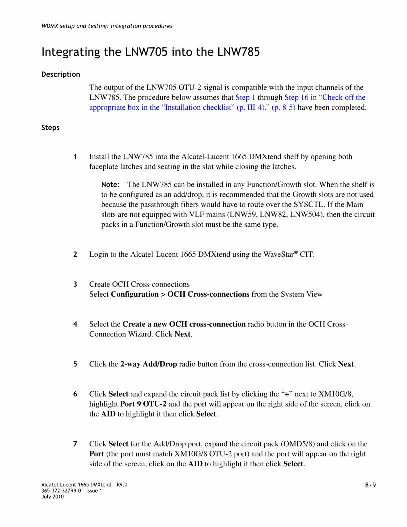
........................................................................................................................................................................Alcatel-Lucent 1665 DMXtend R9.0365-372-327R9.0 Issue 1July 2010
8-9
........................................................................................................................................................................
WDMX setup and testing: integration procedures
Integrating the LNW705 into the LNW785
Description
The output of the LNW705 OTU-2 signal is compatible with the input channels of the LNW785. The procedure below assumes that Step 1 through Step 16 in “Check off the appropriate box in the “Installation checklist” (p. III-4).” (p. 8-5) have been completed.
Steps
................................................................................................................................................
1 Install the LNW785 into the Alcatel-Lucent 1665 DMXtend shelf by opening both faceplate latches and seating in the slot while closing the latches.
Note: The LNW785 can be installed in any Function/Growth slot. When the shelf is to be configured as an add/drop, it is recommended that the Growth slots are not used because the passthrough fibers would have to route over the SYSCTL. If the Main slots are not equipped with VLF mains (LNW59, LNW82, LNW504), then the circuit packs in a Function/Growth slot must be the same type.
................................................................................................................................................
2 Login to the Alcatel-Lucent 1665 DMXtend using the WaveStar® CIT.
................................................................................................................................................
3 Create OCH Cross-connectionsSelect Configuration > OCH Cross-connections from the System View
................................................................................................................................................
4 Select the Create a new OCH cross-connection radio button in the OCH Cross-Connection Wizard. Click Next.
................................................................................................................................................
5 Click the 2-way Add/Drop radio button from the cross-connection list. Click Next.
................................................................................................................................................
6 Click Select and expand the circuit pack list by clicking the “+” next to XM10G/8, highlight Port 9 OTU-2 and the port will appear on the right side of the screen, click on the AID to highlight it then click Select.
................................................................................................................................................
7 Click Select for the Add/Drop port, expand the circuit pack (OMD5/8) and click on the Port (the port must match XM10G/8 OTU-2 port) and the port will appear on the right side of the screen, click on the AID to highlight it then click Select.

........................................................................................................................................................................8-10 Alcatel-Lucent 1665 DMXtend R9.0
365-372-327R9.0 Issue 1July 2010
........................................................................................................................................................................
WDMX setup and testing: integration procedures
................................................................................................................................................
8 Click Next, then Finish and complete the cross-connection by clicking on Yes in the confirmation window.
................................................................................................................................................
9 Connect fibers from the LNW705 Port 9 to the corresponding channel on the LNW785 while observing proper optical power levels and cleaning procedures.
................................................................................................................................................
10 Repeat Step 1 though Step 9 at the remote node.
................................................................................................................................................
11 Connect the Transmit fibers to the OTS port on the LNW785 at each end of the span, following proper fiber cleaning procedures.
................................................................................................................................................
12 Connect the Receive fibers, while observing optical power requirements and cleaning procedures
................................................................................................................................................
13 Observe test set and verify error-free transmission. If only one test set is available, connect a fiber from the In port to the Out port of the PTM in port 1 at one end. Use the information listed in Table 8-4, “Attenuation Table” (p. 8-19) to determine the proper LBO/Attenuator.
Note: Test duration may be determined by engineering specification or by the end customer.
................................................................................................................................................
14 Disconnect test set(s) and fiber jumper from ports.
................................................................................................................................................
15 Check off the appropriate box in Table I-3, Installation acceptance checklist.
........................................................................................................................................................E N D O F S T E P S
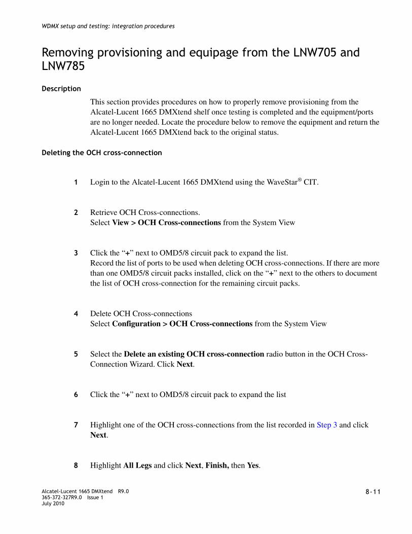
........................................................................................................................................................................Alcatel-Lucent 1665 DMXtend R9.0365-372-327R9.0 Issue 1July 2010
8-11
........................................................................................................................................................................
WDMX setup and testing: integration procedures
Removing provisioning and equipage from the LNW705 and LNW785
Description
This section provides procedures on how to properly remove provisioning from the Alcatel-Lucent 1665 DMXtend shelf once testing is completed and the equipment/ports are no longer needed. Locate the procedure below to remove the equipment and return the Alcatel-Lucent 1665 DMXtend back to the original status.
Deleting the OCH cross-connection
................................................................................................................................................
1 Login to the Alcatel-Lucent 1665 DMXtend using the WaveStar® CIT.
................................................................................................................................................
2 Retrieve OCH Cross-connections.Select View > OCH Cross-connections from the System View
................................................................................................................................................
3 Click the “+” next to OMD5/8 circuit pack to expand the list.Record the list of ports to be used when deleting OCH cross-connections. If there are more than one OMD5/8 circuit packs installed, click on the “+” next to the others to document the list of OCH cross-connection for the remaining circuit packs.
................................................................................................................................................
4 Delete OCH Cross-connectionsSelect Configuration > OCH Cross-connections from the System View
................................................................................................................................................
5 Select the Delete an existing OCH cross-connection radio button in the OCH Cross-Connection Wizard. Click Next.
................................................................................................................................................
6 Click the “+” next to OMD5/8 circuit pack to expand the list
................................................................................................................................................
7 Highlight one of the OCH cross-connections from the list recorded in Step 3 and click Next.
................................................................................................................................................
8 Highlight All Legs and click Next, Finish, then Yes.

........................................................................................................................................................................8-12 Alcatel-Lucent 1665 DMXtend R9.0
365-372-327R9.0 Issue 1July 2010
........................................................................................................................................................................
WDMX setup and testing: integration procedures
................................................................................................................................................
9 Repeat Step 5 through Step 8 for all remaining OCH cross-connections recorded in Step 3.
................................................................................................................................................
10 End the OCH cross-connection Wizard session by clicking Close.
........................................................................................................................................................E N D O F S T E P S
Delete LNW785 circuit pack
................................................................................................................................................
1 Remove the LNW785 circuit pack from the Alcatel-Lucent 1665 DMXtend shelf.
................................................................................................................................................
2 Update the Alcatel-Lucent 1665 DMXtend inventory.Select Configuration > Update System > Update Inventory
................................................................................................................................................
3 Click Yes to acknowledge the request.
........................................................................................................................................................E N D O F S T E P S
Delete low-speed PTM
................................................................................................................................................
1 Remove Low Speed PTM from LNW705 by reversing the procedure in Appendix E, “Install pluggable transmission modules” (p. E-3).
................................................................................................................................................
2 If removing the LNW705 from the shelf proceed to Delete LNW705 circuit pack (p. 8-13), otherwise provision the port back to Signal Type Not Available.STNA Select Configuration > Equipment
................................................................................................................................................
3 Click the “+” next to the XM10G/8 that had the PTM installed to expand the list.
................................................................................................................................................
4 Locate the port where the PTM was installed and highlight the port and click Select.
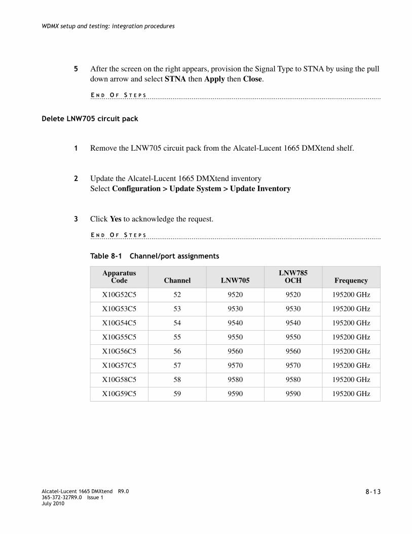
........................................................................................................................................................................Alcatel-Lucent 1665 DMXtend R9.0365-372-327R9.0 Issue 1July 2010
8-13
........................................................................................................................................................................
WDMX setup and testing: integration procedures
................................................................................................................................................
5 After the screen on the right appears, provision the Signal Type to STNA by using the pull down arrow and select STNA then Apply then Close.
........................................................................................................................................................E N D O F S T E P S
Delete LNW705 circuit pack
................................................................................................................................................
1 Remove the LNW705 circuit pack from the Alcatel-Lucent 1665 DMXtend shelf.
................................................................................................................................................
2 Update the Alcatel-Lucent 1665 DMXtend inventorySelect Configuration > Update System > Update Inventory
................................................................................................................................................
3 Click Yes to acknowledge the request.
........................................................................................................................................................E N D O F S T E P S
Table 8-1 Channel/port assignments
Apparatus Code Channel LNW705
LNW785OCH Frequency
X10G52C5 52 9520 9520 195200 GHz
X10G53C5 53 9530 9530 195200 GHz
X10G54C5 54 9540 9540 195200 GHz
X10G55C5 55 9550 9550 195200 GHz
X10G56C5 56 9560 9560 195200 GHz
X10G57C5 57 9570 9570 195200 GHz
X10G58C5 58 9580 9580 195200 GHz
X10G59C5 59 9590 9590 195200 GHz

........................................................................................................................................................................8-14 Alcatel-Lucent 1665 DMXtend R9.0
365-372-327R9.0 Issue 1July 2010
........................................................................................................................................................................
WDMX setup and testing: integration procedures
LNW705 XM10G/8 port guidelines
The following table list the PTM restrictions and guidelines.
Table 8-2 XM10G/8 PTM port guidelines
Connecting the ring (Mains) to the WDMX
Description
This section provides guidance on how to integrate an OC-48/OC-192 into the WDMX. Depending on the Main circuit packs and the port rate, the ring can be integrated through the LNW785. Only the LNW141 can be integrated directly into the LNW785 providing the circuit pack is equipped with one of the compatible PTMs listed in Table 8-3, “Channel/port assignments” (p. 8-19).
Important! The procedures in this section make two assumptions, the first is that the span between LNW785s is established while the second is that this is a new turn-up and not on an existing network.
LNW785/OC192
The LNW785 span is established and tested using the Procedure , “Turn-up and test the LNW785 8-channel OMD” (p. 8-4). In some instances, only one direction may be added to the WDMX circuit pack. Main 1 is always referred to as the West direction, while Main 2 is the East
Port Number
Signal Type
OC-3/STM1 OC-12/STM4 OC-48/STM16 1Gbe 1GFC 2GFC
1 Yes Yes Yes Yes Yes Yes
2 Yes Yes No Yes Yes No
3 Yes Yes Yes Yes Yes Yes
4 Yes Yes No Yes Yes No
5 Yes Yes Yes Yes Yes Yes
6 Yes Yes No Yes Yes No
7 Yes Yes Yes Yes Yes Yes
8 Yes Yes No Yes Yes No

........................................................................................................................................................................Alcatel-Lucent 1665 DMXtend R9.0365-372-327R9.0 Issue 1July 2010
8-15
........................................................................................................................................................................
WDMX setup and testing: integration procedures
................................................................................................................................................
1 Determine the direction of the Span, Main 1 or Main 2.
................................................................................................................................................
2 Install an OC-192 PTM in the assigned port slot in the Main circuit pack see Table 8-3, “Channel/port assignments” (p. 8-19).
Note: Only the first 4 wavelengths can be used in the LNW141, PTMs X10G52C5 through X10G55C5.
................................................................................................................................................
3 Login to the Alcatel-Lucent 1665 DMXtend using the WaveStar® CIT.
................................................................................................................................................
4 Provision the PTM/OTU-2Select Configuration > Equipment from the System View
................................................................................................................................................
5 Click the “+” next to Main 1 circuit pack to expand the list.
................................................................................................................................................
6 Highlight the PTM and click Select.
................................................................................................................................................
7 Enter the Frequency in the Expected Frequency and click Apply, then Close.
Note: The frequency is determined by the PTM inserted in Port 9. See the LNW785 column in Table 8-3, “Channel/port assignments” (p. 8-19) for acceptable values.
................................................................................................................................................
8 Create OCH Cross-connectionsSelect Configuration > OCH Cross-connections from the System View
................................................................................................................................................
9 Select the Create a new OCH cross-connection radio button in the OCH Cross-Connection Wizard. Click Next.
................................................................................................................................................
10 Click the 2-way Add/Drop radio button from the cross-connection list. Click Next.

........................................................................................................................................................................8-16 Alcatel-Lucent 1665 DMXtend R9.0
365-372-327R9.0 Issue 1July 2010
........................................................................................................................................................................
WDMX setup and testing: integration procedures
................................................................................................................................................
11 Click Select and expand the circuit pack list by clicking the “+” next to Main 1, highlight Port 1 OTU-2 and the port will appear on the right side of the screen, click on the AID to highlight it then click Select.
................................................................................................................................................
12 Click Select for the Add/Drop port, expand the circuit pack (OMD5/8) and click on the Port (the port must match Main 1 OTU-2 port) and the port will appear on the right side of the screen, click on the AID to highlight it then click Select.
................................................................................................................................................
13 Connect the fibers from Main 1/Main2 PTM to the corresponding channel in the LNW785 while observing proper optical levels, fiber cleaning procedures and fiber routing in the shelf.
................................................................................................................................................
14 Repeat Step 1 to Step 13 at the other end of the circuit.
Result: Once both ends are completed the Mains should go into service and LOS alarms cleared between the nodes.
................................................................................................................................................
15 If configuring the other direction, repeat Step 1 to Step 13.
................................................................................................................................................
16 Check off the appropriate box in the “Installation checklist” (p. III-4).
........................................................................................................................................................E N D O F S T E P S
Removing provisioning and equipage from the LNW785
Description
This section provides procedures on how to properly remove provisioning from the Alcatel-Lucent 1665 DMXtend shelf once testing is completed and the equipment/ports are no longer needed. Locate the procedure below to remove the equipment and return the Alcatel-Lucent 1665 DMXtend back to the original status.

........................................................................................................................................................................Alcatel-Lucent 1665 DMXtend R9.0365-372-327R9.0 Issue 1July 2010
8-17
........................................................................................................................................................................
WDMX setup and testing: integration procedures
Deleting the OCH cross-connection
................................................................................................................................................
1 Login to the Alcatel-Lucent 1665 DMXtend using the WaveStar® CIT.
................................................................................................................................................
2 Retrieve OCH Cross-connections.Select View > OCH Cross-connections from the System View
................................................................................................................................................
3 Click the “+” next to OMD5/8 circuit pack to expand the list.Record the list of ports to be used when deleting OCH cross-connections. If there are more than one OMD5/8 circuit packs installed, click on the “+” next to the others to document the list of OCH cross-connection for the remaining circuit packs.
................................................................................................................................................
4 Delete OCH Cross-connectionsSelect Configuration > OCH Cross-connections from the System View
................................................................................................................................................
5 Select the Delete an existing OCH cross-connection radio button in the OCH Cross-Connection Wizard. Click Next.
................................................................................................................................................
6 Click the “+” next to OMD5/8 circuit pack to expand the list
................................................................................................................................................
7 Highlight one of the OCH cross-connections from the list recorded in Step 3 and click Next.
................................................................................................................................................
8 Highlight All Legs and click Next, Finish, then Yes.
................................................................................................................................................
9 Repeat Step 5 through Step 8 for all remaining OCH cross-connections recorded in Step 3.
................................................................................................................................................
10 End the OCH cross-connection Wizard session by clicking Close.

........................................................................................................................................................................8-18 Alcatel-Lucent 1665 DMXtend R9.0
365-372-327R9.0 Issue 1July 2010
........................................................................................................................................................................
WDMX setup and testing: integration procedures
................................................................................................................................................
11 Check off the appropriate box in the “Installation checklist” (p. III-4).
........................................................................................................................................................E N D O F S T E P S
Delete LNW785 circuit pack
................................................................................................................................................
1 Remove the LNW785 circuit pack from the Alcatel-Lucent 1665 DMXtend shelf.
................................................................................................................................................
2 Update the Alcatel-Lucent 1665 DMXtend inventorySelect Configuration > Update System > Update Inventory
................................................................................................................................................
3 Click Yes to acknowledge the request.
................................................................................................................................................
4 Check off the appropriate box in the “Installation checklist” (p. III-4).
........................................................................................................................................................E N D O F S T E P S

........................................................................................................................................................................Alcatel-Lucent 1665 DMXtend R9.0365-372-327R9.0 Issue 1July 2010
8-19
........................................................................................................................................................................
WDMX setup and testing: integration procedures
Table 8-3 Channel/port assignments
Table 8-4 Attenuation Table
Apparatus Code Channel LNW705
LNW785OCH Frequency
X10G52C5 52 9520 9520 195200 GHz
X10G53C5 53 9530 9530 195200 GHz
X10G54C5 54 9540 9540 195200 GHz
X10G55C5 55 9550 9550 195200 GHz
X10G56C5 56 9560 9560 195200 GHz
X10G57C5 57 9570 9570 195200 GHz
X10G58C5 58 9580 9580 195200 GHz
X10G59C5 59 9590 9590 195200 GHz
Optics Circuit packReceived power (dBM)
LBO (dB)
OC-3 (high speed)
LNW40 -8.0 to -28.0 0
LNW140 -8.0 to -28.0 0
LNW601 0.0 to -15.0 10
-15.0 to -34.0 0
Low-speed optics (OC-48)
LNW31 (OC-48) 0.0 to -18.0 0
OC-12 (high speed)
LNW38 -8.0 to -28.0 0
LNW51 -8.0 to -30.5 0
LNW302 TBS
LNW380 -8.0 to -29.0 0
LNW382 TBS
OC-48 PTM (pluggable transmission module) optics
LNW41/55/62 LR-1 Optics -9.0 to -27.0 10
LNW41/55/62 LR-2 Optics -9.0 to -28.0 10
LNW41/55/62 SR-1 Optics -3.0 to -18.0 5

........................................................................................................................................................................8-20 Alcatel-Lucent 1665 DMXtend R9.0
365-372-327R9.0 Issue 1July 2010
........................................................................................................................................................................
WDMX setup and testing: integration procedures
OC-192 VLF high speed PTM (pluggable transmission module) optics
LNW141, LR-2 Optics +4.0 to 0.0 15
0.0 to -7.0 10
-7.0 to -24.0 0
LNW141, IR-2 Optics +2.0 to -1.0 5
-1.0 to -14 0
LNW141, SR-1 Optics -1.0 to -11.0 0
PTM (pluggable transmission module)
LNW37/45/55 OC-3 SR-1 -8.0 to -23.0 0
LNW37/45/55 OC-3 IR-1 -8.0 to -28.0 0
LNW37/45/55 OC-3 LR-1 0.0 to -5.0 15
-5.0 to -10 10
-10 to -34.0 0
LNW49/55 OC-12 SR-1
-8.0 to -28.0 0
LNW49/55 OC-12 IR-1
-8.0 to -28.0 0
LNW49/55 OC-12 LR-1 +2.0 to -5.0 15
-5.0 to -15 10
-15 to -28.0 0
Optics Circuit packReceived power (dBM)
LBO (dB)
OC-3 (high speed)
LNW40 -8.0 to -28.0 0
LNW140 -8.0 to -28.0 0
Optics Circuit packReceived power (dBM)
LBO (dB)

IV-1Alcatel-Lucent 1665 DMXtend R9.0365-372-327R9.0 Issue 1July 2010
............................................................................................................................................................................................................................................................
Part IV: Miscellaneous detailed installation procedure and reference material
Overview
Purpose
This section provides supplementary information that is useful when installing the Alcatel-Lucent 1665 Data Multiplexer Extend (Alcatel-Lucent 1665 DMXtend) system and using this Installation Manual.
This section is comprised of the following appendixes:
Appendix A, “Fiber cleaning”
Appendix B, “Pluggable Transmission Module (PTM) installation”
Appendix C, “Installing fiber connectors and LBOs”
Appendix D, “Backplane pin replacement”
Appendix E, “Fiber labeling”

............................................................................................................................................................................................................................................................IV-2 Alcatel-Lucent 1665 DMXtend R9.0
365-372-327R9.0 Issue 1July 2010
............................................................................................................................................................................................................................................................
Miscellaneous detailed installation procedure and reference material

A-1Alcatel-Lucent 1665 DMXtend R9.0365-372-327R9.0 Issue 1July 2010
............................................................................................................................................................................................................................................................
A Fiber cleaning
Overview
Purpose
This appendix describes the Alcatel-Lucent recommended method for the cleaning and inspection of optical connectors using specific tools and materials that have been proven to be effective in the assembly and testing of optical transmission equipment. It is critical that connector faces are clean and free from particular contamination to assure proper performance and reliability of lightwave systems. With the modern high speed, high power, and wider bandwidth optical transmission systems, clean connectors along the optical path are essential for successful operation.
Contents
This appendix provides information on the following topics:
Objectives
This chapter provides information to perform the following:
1. Properly clean an optical connector
2. Inspect an optical connector for cleanliness
3. Clean PTM optical modules.
Equipment requirements and recommendations A-2
Safety instructions A-3
Cleaning/inspecting optical connectors A-3
Cleaning pluggable optics module A-9

............................................................................................................................................................................................................................................................A-2 Alcatel-Lucent 1665 DMXtend R9.0
365-372-327R9.0 Issue 1July 2010
............................................................................................................................................................................................................................................................
Fiber cleaning
Related information
A course on connector cleaning and the connector inspection process is now offered through Alcatel-Lucent University, Course Code: LMC200H “Understanding Fiber Optic Cleaning, Inspection and Testing.” To learn more about this course, consult your local Alcatel-Lucent Account Representative.
Equipment requirements and recommendations
Description
For proper cleaning, the following equipment and materials are recommended:
Table A-1 Required and recommended equipment and materials
Product Model/description Comcode ITE #Installation order #
Optical Fiber Scope Noyes OFS 300-200X 408197028 ITE-7129 33712900
2.5mm Universal adapter cap
For use with the Noyes OFS 300-200X
408197044 ITE-7129D1 33712901
1.25mm Universal adapter cap
For use with the Noyes OFS 300-200X
408197069 ITE-7129D2 33712902
Video Fiber Scope1 Noyes VFS-1 TBD TBD TBD
Individual presaturated alcohol wipes
99% pure isopropyl alcohol
901375147 ITE-7136 33713600
CLETOP Cleaning Cassette
Type A Reel 901375154 ITE-7137 33713700
CLETOP Cleaning Cassette Replacement Reel
Type A Reel 901375014 ITE-7137 D1
33713701
Luminex Stick port cleaners
1.25 mm 901375030 ITE-7134 33713400
Luminex Stick port cleaners
2.5 mm 901375022 ITE-7135 33713500
Luminex Cloth 5.5” x 5.5” 408201226 R6033 23603300

............................................................................................................................................................................................................................................................Alcatel-Lucent 1665 DMXtend R9.0365-372-327R9.0 Issue 1July 2010
A-3
............................................................................................................................................................................................................................................................
Fiber cleaning
Note: The equipment and material listed above has been tested and is proven effective when used in conjunction with this procedure. Substitution of equipment or materials is at the discretion of the user and is not recommended.
Safety instructions
Safety warnings
Never view an energized optical cable with the naked eye or with an optical magnifying instrument. Disconnected or separated optical connectors may emit invisible laser radiation and direct exposure can severely injure the eye. If inspecting the endface of a connector with a fiberscope, be absolutely certain that the system is deactivated.
Alcohol is flammable and is harmful if swallowed, inhaled or absorbed through the skin. Keep alcohol away from heat, sparks, or flame. Avoid contact with eyes, skin and clothing.
Cleaning/inspecting optical connectors
Introduction
The procedure that follows utilizes the “Wet/Dry” method for connector cleaning. This method first applies a “wet” solvent such as high purity alcohol to the connector endface to dissolve/remove any organic particulate or oily films, followed by a “dry” double clean wipe using the CLETOP cleaning cassette.
Notes: 1. This equipment may not be necessary at all locations. It is to be used when the ports need
to be verified for cleanliness. If care is exercised when cleaning fibers, the video scope may not be needed.
Product Model/description Comcode ITE #Installation order #
WARNING
Laser hazard
WARNING
Noxious substance hazard

............................................................................................................................................................................................................................................................A-4 Alcatel-Lucent 1665 DMXtend R9.0
365-372-327R9.0 Issue 1July 2010
............................................................................................................................................................................................................................................................
Fiber cleaning
This procedure is recommended for connector ferrules 2.5 mm and 1.25 mm in diameter associated with ST, SC, FC, and LC connectors. The ferrule of a fiber optic connector consists of a ceramic or stainless steel cylinder with a hole located longitudinally down the center of its axis, allowing enough tolerance for a fiber to pass through.
All optical connectors should be cleaned prior to being connected. Keep the protective ferrule dust cap on the connector until initiating the cleaning process.
Cleaning procedure
The following cleaning procedure is acceptable for field service/installation activities:
........................................................................................................................................................................................................................
1 Remove the dust cap from the connector ferrule, thus exposing the connector endface.
........................................................................................................................................................................................................................
2 Open an individual foil packet of pre-saturated isopropyl alcohol (99% pure) wipe.
See Figure A-1, “Cleaning the ferrule endface” (p. A-4).
Grasp the connector housing and place the connector ferrule endface perpendicular to the alcohol wipe.
Drag it against the wipe three (3) times in a figure eight pattern. This action applies the alcohol solvent to the endface and initially loosens and scrubs away organic/solid contaminates.
Figure A-1 Cleaning the ferrule endface
........................................................................................................................................................................................................................
3 If a CLETOP cassette cleaner is not available, proceed with Step 7. Otherwise, hold the CLETOP cassette cleaner in the palm of your hand with the cassette shutter door facing up. See Figure A-2, “CLETOP cleaner” (p. A-5).

............................................................................................................................................................................................................................................................Alcatel-Lucent 1665 DMXtend R9.0365-372-327R9.0 Issue 1July 2010
A-5
............................................................................................................................................................................................................................................................
Fiber cleaning
Rotate the cassette lever all the way down with your thumb. Do not release the lever. The lever advances the “dry” Luminex cleaning cloth inside the case and simultaneously opens the shutter. The CLETOP cassette shutter door is now open and ready for cleaning the connector.
Figure A-2 CLETOP cleaner
........................................................................................................................................................................................................................
4 Insert and press the connector ferrule endface perpendicular against the cleaning cloth in the first of two slots of the cleaner. See Figure A-3, “Acceptability criteria for fiber cleaning” (p. A-7).
Drag it down (in the direction indicated by the arrows on the cleaner). Make certain not to release the lever of the cassette.
........................................................................................................................................................................................................................
5 Lift the connector from the first slot and rotate it 90 degrees and repeat the downward motion using the second slot. Be sure the ferrule is pressed snug against the cleaning cloth while dragging the ferrule to assure the proper cleaning action.
........................................................................................................................................................................................................................
6 Release the cassette lever allowing the shutter door to close to its initial position. Continue with Step 8.
........................................................................................................................................................................................................................
7 Wrap a Luminex cleaning cloth around the ferrule and rotate the connector housing, cleaning the outside periphery of ferrule.

............................................................................................................................................................................................................................................................A-6 Alcatel-Lucent 1665 DMXtend R9.0
365-372-327R9.0 Issue 1July 2010
............................................................................................................................................................................................................................................................
Fiber cleaning
Follow this by folding an unused portion of the cloth over the end of the ferrule endface and then with light pressure from the thumb, slightly drag the cloth from the center of the ferrule to the edge while rotating the connector 360 degrees. If the Luminex cleaning cloth is not available, a lint free cleanroom optic wipe can be used. The Luminex cleaning cloth is washable and can be used multiple times, optic wipes are single use and disposable.
........................................................................................................................................................................................................................
8 Inspect the connector for cleanliness. If necessary, repeat the cleaning process. See “Connector inspection” (p. A-6).
........................................................................................................................................................E N D O F S T E P S
Connector inspection
After cleaning the connector, inspect the ferrule endface to ensure that it is free from any particulate contamination using an optical fiber inspection scope of at least 200X magnification. When using an optical fiber scope (for example, the Noyes OFS 300-200X) exercise extreme caution to assure fiber being examined is de-energized.
........................................................................................................................................................................................................................
1 Follow the instructions in the manual provided with the Optical Fiber Scope to view the ferrule endface of the fiber under inspection.
........................................................................................................................................................................................................................
2 The visual area of the ferrule endface (ferrule and fiber) as observed by the inspection system/scope should be free of any contaminates. See Figure A-3, “Acceptability criteria for fiber cleaning” (p. A-7).
WARNINGWhen using an optical power meter to verify the connector and fiber to be cleaned, take special precaution to make sure that no power is being emitted from the fiber before viewing.

............................................................................................................................................................................................................................................................Alcatel-Lucent 1665 DMXtend R9.0365-372-327R9.0 Issue 1July 2010
A-7
............................................................................................................................................................................................................................................................
Fiber cleaning
Repeat the Cleaning procedure if the fiber endface does not meet the following requirements:
Requirement: No fixed type of contamination (contaminates that remain at the same location after 3 wet-dry cleaning cycles), regardless of size, is allowed in the restricted area of the glass fiber endface.
Requirement: The restricted area is defined as ~66 microns (µm) diameter for both singlemode and multimode fibers.
Requirement: No chips, cracks or scratches are allowed near the core of the glass fiber endface.
Requirement: No large floating (loose) contaminates are allowed on the glass fiber and ceramic ferrule endface.
Figure A-3 Acceptability criteria for fiber cleaning
........................................................................................................................................................................................................................
3 After the connector has been verified to be cleaned, it should be immediately inserted into the adapter buildout of the optical component. This will assure maximum cleanliness and effectiveness of the connector.
........................................................................................................................................................................................................................
4 If the cleaned connector can not be immediately connected to a corresponding adapter, the connector ferrule must be protected with a connector dust cap. Before placing the cap on the ferrule, make sure the cap is clean. This can be accomplished by inserting a CLETOP stick cleaner (swab) of the same inside diameter as the cap (either 2.5 or 1.25 mm) and rotating the stick 360 degrees three (3) times. Following this procedure, carefully place the
66um
core
fiber
Restricted Area1/2 SM Core + 1/2 FiberDiameters - 66 µm dia.
No Loose or No FixedContamination
Monitor ViewingArea
No LOOSE contamination or particulate fibers in viewing area. If not removable in 3 cleaning attempts, it is defined as fixed particulate
Fixed particles (<8.0µm in size) allowed in this area.

............................................................................................................................................................................................................................................................A-8 Alcatel-Lucent 1665 DMXtend R9.0
365-372-327R9.0 Issue 1July 2010
............................................................................................................................................................................................................................................................
Fiber cleaning
cap over the ferrule. When the cleaned connector is ready for assembly, it should be re-inspected for cleanliness prior to connection.
........................................................................................................................................................E N D O F S T E P S
Fiber adapters or circuit pack connectors
During testing and/or trouble shooting activities it may be necessary to clean the optical buildout adapter or the circuit pack connector. The following procedure is recommended
........................................................................................................................................................................................................................
1 Using the appropriate CLETOP stick cleaner (2.5 mm for SC, ST, and FC connectors, 1.25 mm for LC connectors) dampen the stick cleaner with Ethyl alcohol using the alcohol wipe. Insert the stick cleaner into the adapter rotating the stick 360 degrees while inserting. Push/rotate stick until the stick cleaner makes contact with the connector. Apply slight pressure upon contact and rotate stick 360 degrees at least three (3) times.
........................................................................................................................................................................................................................
2 Remove the stick cleaner rotating it upon removal.
........................................................................................................................................................................................................................
3 Using a dry CLETOP stick cleaner of appropriate diameter, repeat the above cleaning procedure. This procedure will clean the side walls of the adapter and the endface of the circuit pack connector.
........................................................................................................................................................................................................................
4 Gently insert the Video Fiber Scope probe into the port until the fiber ferrule comes into view.
........................................................................................................................................................................................................................
5 Verify that the fiber ferrule is clean. Repeat Step 1 through Step 3 if the fiber does not meet the requirements specified in “Connector inspection” (p. A-6).
........................................................................................................................................................E N D O F S T E P S
CAUTIONDo not attempt to clean ports equipped with yellow Light guide BuildOut (LBO) attenuators. Attenuators contain a thin glass lens that is extremely fragile. The LBO will be damaged if cleaned using this method.
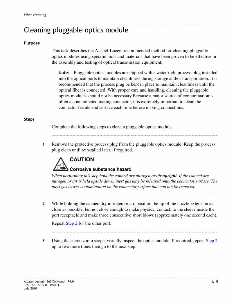
............................................................................................................................................................................................................................................................Alcatel-Lucent 1665 DMXtend R9.0365-372-327R9.0 Issue 1July 2010
A-9
............................................................................................................................................................................................................................................................
Fiber cleaning
Cleaning pluggable optics module
Purpose
This task describes the Alcatel-Lucent recommended method for cleaning pluggable optics modules using specific tools and materials that have been proven to be effective in the assembly and testing of optical transmission equipment.
Note: Pluggable optics modules are shipped with a water-tight process plug installed into the optical ports to maintain cleanliness during storage and/or transportation. It is recommended that the process plug be kept in place to maintain cleanliness until the optical fiber is connected. With proper care and handling, cleaning the pluggable optics modules should not be necessary.Because a major source of contamination is often a contaminated mating connector, it is extremely important to clean the connector ferrule end surface each time before making connections.
Steps
Complete the following steps to clean a pluggable optics module.
........................................................................................................................................................................................................................
1 Remove the protective process plug from the pluggable optics module. Keep the process plug clean until reinstalled later, if required.
When performing this step hold the canned dry nitrogen or air upright. If the canned dry nitrogen or air is held upside down, inert gas may be released onto the connector surface. The inert gas leaves contamination on the connector surface that can not be removed.
........................................................................................................................................................................................................................
2 While holding the canned dry nitrogen or air, position the tip of the nozzle extension as close as possible, but not close enough to make physical contact, to the sleeve inside the port receptacle and make three consecutive short blows (approximately one second each).
Repeat Step 2 for the other port.
........................................................................................................................................................................................................................
3 Using the stereo zoom scope, visually inspect the optics module. If required, repeat Step 2 up to two more times then go to the next step.
CAUTION
Corrosive substance hazard

............................................................................................................................................................................................................................................................A-10 Alcatel-Lucent 1665 DMXtend R9.0
365-372-327R9.0 Issue 1July 2010
............................................................................................................................................................................................................................................................
Fiber cleaning
........................................................................................................................................................................................................................
4 If required, insert a CLETOP stick into the transmit (TX) port sleeve until vertical force can be applied to the fiber stub end surface. Rotate the CLETOP stick five full rounds.
........................................................................................................................................................................................................................
5 Using the stereo zoom scope, visually inspect the optics module. If required, repeat Step 4.
........................................................................................................................................................................................................................
6 If required, reinstall the process plug into the optical ports to maintain cleanliness.
........................................................................................................................................................E N D O F S T E P S
CAUTIONThis step should only be performed on the transmit (TX) port if the air blows did not work. Do not perform this step on the receive (RX) port. The receive (RX) port contains a lens for focusing a wide input. The lens is more easily scratched than cleaned.
CAUTIONIt is recommended that the process plug be installed into the optical ports on the pluggable optics module to maintain cleanliness until the optical fiber is connected.
B-1Alcatel-Lucent 1665 DMXtend R9.0365-372-327R9.0 Issue 1July 2010
............................................................................................................................................................................................................................................................
B Pluggable Transmission Module (PTM) installation
Overview
Purpose
This chapter describes the how to insert a Pluggable Transmission Module (PTM) into a Alcatel-Lucent 1665 Data Multiplexer Extend (Alcatel-Lucent 1665 DMXtend) circuit pack. These PTMs were once referred to as Small Form Programmable (SFP)s.
Contents
This chapter contains the following:
PTM modules B-2
Install pluggable modules B-8

............................................................................................................................................................................................................................................................B-2 Alcatel-Lucent 1665 DMXtend R9.0
365-372-327R9.0 Issue 1July 2010
............................................................................................................................................................................................................................................................
Pluggable Transmission Module (PTM) installation
PTM modules
Alcatel-Lucent approved Class 1 PTM transceivers
The following table lists all the current approved PTM modules to be used with Alcatel-Lucent 1665 DMXtend.
Table B-1 Alcatel-Lucent approved PTMs
NameOptical module code/commode Description
Compatible circuit packs
S15512 OC3SR1-I1109602599
OC3 PTM TRCVR Short Reach - SR1
LNW37, LNW45LNW55, LNW84
OC3LR1-I1 OC3LR1-I1 109453886
OC3 PTM TRCVR Long Reach - LR1
LNW37, LNW45LNW55, LNW84, LNW302
OC3IR1-I1 OC3IR1-I1 109453894
OC3 PTM TRCVR Intermediate Reach IR1
LNW37, LNW45LNW55, LNW84, LNW302
OC3X12X48-IR1-I1 OC3X12X48-IR1-I1
109708131
OC3/STM1/OC12/STM4/OC48/STM16 SFP, 15km, 1310nm
LNW55, LNW84
OC3X12X48-LR1-I1 OC3X12X48-LR1-I1
109708149
OC3/STM1/OC12/ STM4/OC48/STM16, 40km, 1310nm
LNW55, LNW84
OC12IR1-I1 OC12IR1-I1 109453902
OC12 PTM TRCVR Intermediate Reach IR1
LNW49, LNW55 LNW84, LNW382
OC12LR1-I1 OC12LR1-I1 109467522
OC12 PTM TRCVR Long Reach LR1
LNW49, LNW55 LNW84, LNW382
OC12LR2-I1 OC12LR2-I1
109604447
OC12 PTM TRCVR Long reach, 1.5 LR-2 (80km), 1510 nm
LNW49, LNW55 LNW84, LNW382
S622C47EL 109664086 OC3/12 622Mb/s Coarse WDM (CDWDM) Ch47 1471nm SM
LNW37, LNW45LNW55, LNW84, LNW302, LNW382
S622C49EL 109664094 OC3/12 622Mb/s Coarse WDM (CDWDM) Ch49 1491 nm SM
LNW37, LNW45LNW55, LNW84, LNW302, LNW382

............................................................................................................................................................................................................................................................Alcatel-Lucent 1665 DMXtend R9.0365-372-327R9.0 Issue 1July 2010
B-3
............................................................................................................................................................................................................................................................
Pluggable Transmission Module (PTM) installation
S622C51EL 109664102 OC3/12 622Mb/s Coarse WDM (CDWDM) Ch51 1511nm SM
LNW37, LNW45LNW55, LNW84, LNW302, LNW382
S622C53EL 109664110 OC3/12 622Mb/s Coarse WDM (CDWDM) Ch53 1531nm SM
LNW37, LNW45LNW55, LNW84, LNW302, LNW382
S622C55EL 109664128 OC3/12 622Mb/s Coarse WDM (CDWDM) Ch55 1551nm SM
LNW37, LNW45LNW55, LNW84, LNW302, LNW382
S622C57EL 109664136 OC3/12 622Mb/s Coarse WDM (CDWDM) Ch57 1571 nm SM
LNW37, LNW45LNW55, LNW84, LNW302, LNW382
S622C59EL 109664144 OC3/12 622Mb/s Coarse WDM (CDWDM) Ch59 1691nm SM
LNW37, LNW45LNW55, LNW84, LNW302, LNW382
S622C61EL 109664151 OC3/12 622Mb/s Coarse WDM (CDWDM) Ch61 1611nm SM
LNW37, LNW45LNW55, LNW84, LNW302, LNW382
OC48SR1-I1 OC48SR1-I1
109564518
OC48 PTM TRCVR
Short Reach, 1.3 SR-1
(2km) 1310 nm
LNW41, LNW55, LNW62, LNW84, LNW402
OM2.5G 1.3LR1 (OC48LR1-I1)
OC48LR1-I1 109493528
OC48 PTM TRCVR 1310 Long Reach LR1
LNW41, LNW55, LNW62, LNW84, LNW402
OC48LR2-I1 OC48LR2-I1 109504431
OC48 PTM TRCVR 1550 Long Reach LR1
LNW41, LNW55, LNW62, LNW84, LNW402
OC192IR2-C1 OC192IR2-C1 109537563
OC192 XFP SM IR2 (40 km) 1550 nm
LNW141
OC192IR2-I1 OC192IR2-I1 109586479
OC192 XFP SM IR2 (40 km) 1550 nm
LNW141
OC192LR2-C1 OC192LR2-C1 109537555
OC192 XFP SM LR2 (80 km) 1550 nm
LNW141
OC192SR1-C1 OC192SR1-C1 109537902
OC192 XFP SM SR1 (2 km) 1310 nm
LNW141
NameOptical module code/commode Description
Compatible circuit packs

............................................................................................................................................................................................................................................................B-4 Alcatel-Lucent 1665 DMXtend R9.0
365-372-327R9.0 Issue 1July 2010
............................................................................................................................................................................................................................................................
Pluggable Transmission Module (PTM) installation
S2D23C6 OC48 DWDM
109610378
OC48/STM16/OTU1 DWDM192.3 THz/1558.983 nm
LNW41, LNW55, LNW62, LNW84, LNW402
S2D25C6 OC48 DWDM
109610394
OC48/STM16/OTU1 DWDM192.5 THz/1557.363 nm
LNW41, LNW55, LNW62, LNW84, LNW402
S2D27C6 OC48 DWDM
109610410
OC48/STM16/OTU1 DWDM192.7 THz/1555.747 nm
LNW41, LNW55, LNW62, LNW84, LNW402
S2D31C6 OC48 DWDM
109610451
OC48/STM16/OTU1 DWDM193.1 THz/1552.524 nm
LNW41, LNW55, LNW62, LNW84, LNW402
S2D33C6 OC48 DWDM
109610477
OC48/STM16/OTU1 DWDM193.3 THz/1550.918 nm
LNW41, LNW55, LNW62, LNW84, LNW402
S2D35C6 OC48 DWDM
109610493
OC48/STM16/OTU1 DWDM193.5 THz/1549.315 nm
LNW41, LNW55, LNW62, LNW84, LNW402
S2D37C6 OC48 DWDM
109610519
OC48/STM16/OTU1 DWDM193.7 THz/1547.715 nm
LNW41, LNW55, LNW62, LNW84, LNW402
S2D45C6 OC48 DWDM
109610600
OC48/STM16/OTU1 DWDM194.5 THz/1541.349 nm
LNW41, LNW55, LNW62, LNW84, LNW402
S2D47C6 OC48 DWDM
109610626
OC48/STM16/OTU1 DWDM194.7 THz/1539.766 nm
LNW41, LNW55, LNW62, LNW84, LNW402
S2D49C6 OC48 DWDM
109610642
OC48/STM16/OTU1 DWDM194.9THz/1538.186 nm
LNW41, LNW55, LNW62, LNW84, LNW402
S2D53C6 OC48 DWDM
109610691
OC48/STM16/OTU1 DWDM195.3 THz/1535.036 nm
LNW41, LNW55, LNW62, LNW84, LNW402
S2D55C6 OC48 DWDM
109610717
OC48/STM16/OTU1 DWDM195.5 THz/1533.465 nm
LNW41, LNW55, LNW62, LNW84, LNW402
NameOptical module code/commode Description
Compatible circuit packs
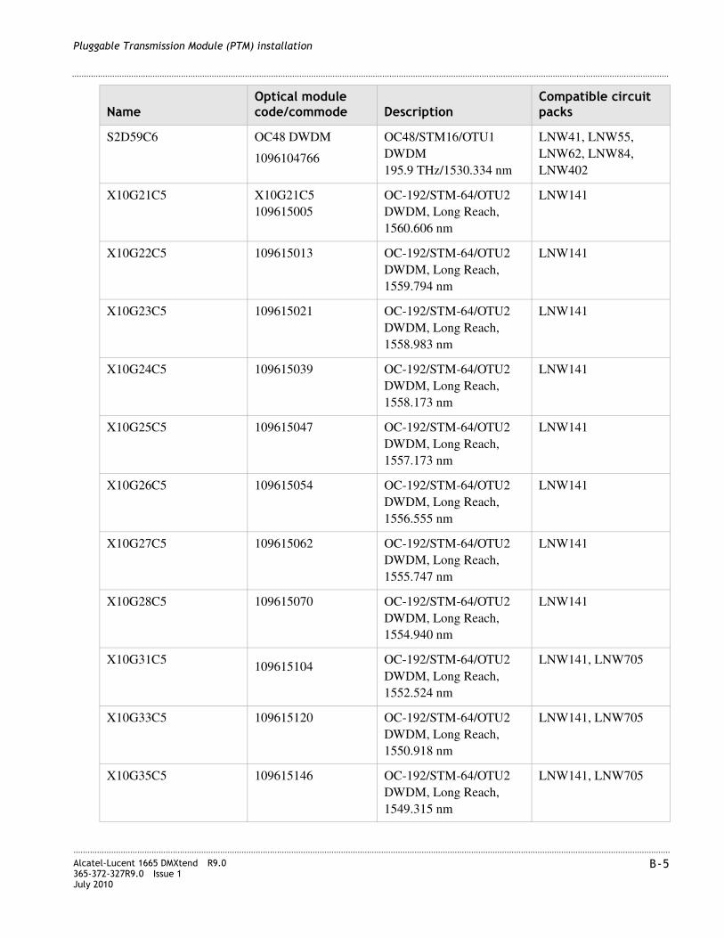
............................................................................................................................................................................................................................................................Alcatel-Lucent 1665 DMXtend R9.0365-372-327R9.0 Issue 1July 2010
B-5
............................................................................................................................................................................................................................................................
Pluggable Transmission Module (PTM) installation
S2D59C6 OC48 DWDM
1096104766
OC48/STM16/OTU1 DWDM195.9 THz/1530.334 nm
LNW41, LNW55, LNW62, LNW84, LNW402
X10G21C5 X10G21C5 109615005
OC-192/STM-64/OTU2 DWDM, Long Reach, 1560.606 nm
LNW141
X10G22C5 109615013 OC-192/STM-64/OTU2 DWDM, Long Reach, 1559.794 nm
LNW141
X10G23C5 109615021 OC-192/STM-64/OTU2 DWDM, Long Reach, 1558.983 nm
LNW141
X10G24C5 109615039 OC-192/STM-64/OTU2 DWDM, Long Reach, 1558.173 nm
LNW141
X10G25C5 109615047 OC-192/STM-64/OTU2 DWDM, Long Reach, 1557.173 nm
LNW141
X10G26C5 109615054 OC-192/STM-64/OTU2 DWDM, Long Reach, 1556.555 nm
LNW141
X10G27C5 109615062 OC-192/STM-64/OTU2 DWDM, Long Reach, 1555.747 nm
LNW141
X10G28C5 109615070 OC-192/STM-64/OTU2 DWDM, Long Reach, 1554.940 nm
LNW141
X10G31C5 109615104 OC-192/STM-64/OTU2 DWDM, Long Reach, 1552.524 nm
LNW141, LNW705
X10G33C5 109615120 OC-192/STM-64/OTU2 DWDM, Long Reach, 1550.918 nm
LNW141, LNW705
X10G35C5 109615146 OC-192/STM-64/OTU2 DWDM, Long Reach, 1549.315 nm
LNW141, LNW705
NameOptical module code/commode Description
Compatible circuit packs
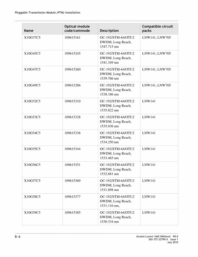
............................................................................................................................................................................................................................................................B-6 Alcatel-Lucent 1665 DMXtend R9.0
365-372-327R9.0 Issue 1July 2010
............................................................................................................................................................................................................................................................
Pluggable Transmission Module (PTM) installation
X10G37C5 109615161 OC-192/STM-64/OTU2 DWDM, Long Reach, 1547.715 nm
LNW141, LNW705
X10G45C5 109615245 OC-192/STM-64/OTU2 DWDM, Long Reach, 1541.349 nm
LNW141, LNW705
X10G47C5 109615260 OC-192/STM-64/OTU2 DWDM, Long Reach, 1539.766 nm
LNW141, LNW705
X10G49C5 109615286 OC-192/STM-64/OTU2 DWDM, Long Reach, 1538.186 nm
LNW141, LNW705
X10G52C5 109615310 OC-192/STM-64/OTU2 DWDM, Long Reach, 1535.822 nm
LNW141
X10G53C5 109615328 OC-192/STM-64/OTU2 DWDM, Long Reach, 1535.036 nm
LNW141
X10G54C5 109615336 OC-192/STM-64/OTU2 DWDM, Long Reach, 1534.250 nm
LNW141
X10G55C5 109615344 OC-192/STM-64/OTU2 DWDM, Long Reach, 1533.465 nm
LNW141
X10G56C5 109615351 OC-192/STM-64/OTU2 DWDM, Long Reach, 1532.681 nm
LNW141
X10G57C5 109615369 OC-192/STM-64/OTU2 DWDM, Long Reach, 1531.898 nm
LNW141
X10G58C5 109615377 OC-192/STM-64/OTU2 DWDM, Long Reach, 1531.116 nm,
LNW141
X10G59C5 109615385 OC-192/STM-64/OTU2 DWDM, Long Reach, 1530.334 nm
LNW141
NameOptical module code/commode Description
Compatible circuit packs

............................................................................................................................................................................................................................................................Alcatel-Lucent 1665 DMXtend R9.0365-372-327R9.0 Issue 1July 2010
B-7
............................................................................................................................................................................................................................................................
Pluggable Transmission Module (PTM) installation
OMFE 100BASE-LX-SM
100BASE-LX-I1 109527812
100 Mb/s Optical FAST Ethernet PTM TRCVR
LNW74, LNW87 LNW170
GE-1X2XFC-LX-C1(1000BASE-LX, 1Gbps and 2Gpbs Fibre-Channel/FICON
GE-1X2XFC-LX-C1 109527804
GbE long-reach, Single Mode PTM supports Ethernet, FICON and Fibre-Channel traffic, LC-type connectors(GbE/FC/2FC/-1310)
LNW64, LNW73, LNW73C, LNW170
OM1G//OMFC 1000BASE-SX//100/200-M5/M6-SN-S
GE1X2XFC-SX-C1 109527796
1X FIBRE Channel or 2X FIBRE Channel or Gbe MM PTM TRCVR
LNW64, LNW73, LNW73C, LNW170
OMESCON MMF ESCON-MM-I1 109523886
ESCON MM PTM TRCVR
LNW73, LNW73C
(1000BASE-SX, 1Gbps) GE-1X2XFC-SX-I1
109570606
GbE short-reach, Single-Mode PTM, supports Ethernet and Fibre-Channel traffic, LC-type connectors, OSP hardened (GbE/FC/2FC-850)
LNW63, LNW64, LNW73, LNW73C, LNW170
(1000BASE-SX, 1Gbps) GE-1X2XFC-LX-I1
109568782
GbE long-reach, Single-Mode PTM, supports Ethernet and Fibre-Channel traffic, LC-type connectors, OSP hardened (GbE/FC/2FC-850)
LNW63, LNW64, LNW73, LNW73C, LNW170
(1000BASE-ZX, 1Gbps) 1000BASE-ZX-I1 109541862
GbE Short-reach, Single-Mode PTM, supports Ethernet, LC-type connectors, and is OSP hardened (GbE-1550)
LNW63, LNW64, LNW170
BASE-T-C1 FE and GbE (electrical- NOT OSP)
109565549 Electrical PTM, provisionable to 100 or 1000 Mbps, Lucent Approved RJ-45 Cat 5-E cable, maximum span length of 100 meters
LNW63, LNW64, LNW170
NameOptical module code/commode Description
Compatible circuit packs

............................................................................................................................................................................................................................................................B-8 Alcatel-Lucent 1665 DMXtend R9.0
365-372-327R9.0 Issue 1July 2010
............................................................................................................................................................................................................................................................
Pluggable Transmission Module (PTM) installation
Install pluggable modules
Task
Complete the following steps to install pluggable optical modules in a circuit pack that has already been installed in a shelf.
........................................................................................................................................................................................................................
1 Determine the circuit pack and socket being equipped with the pluggable optical module.
........................................................................................................................................................................................................................
2 Hold the optical connector/latch-end of the module in your left hand with the gold fingers facing you. The module should be positioned in manner similar to Figure B-1, “Pluggable optics module” (p. B-8).
Figure B-1 Pluggable optics module
Note: Do not remove the dust plug unless you are ready to connect fibers or if you need to clean the module.
........................................................................................................................................................................................................................
3 Referring to Figure B-2, “Module types” (p. B-9), determine the type of latching mechanism on the pluggable optical module purchased.
MA-DMX-422
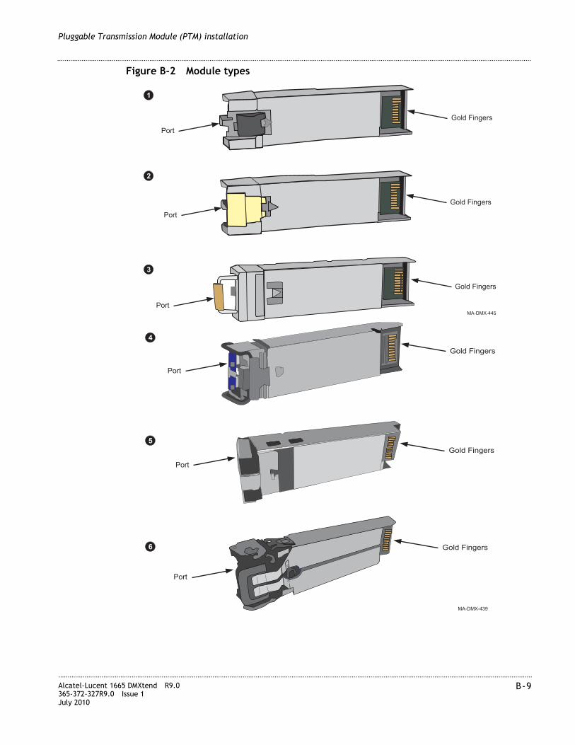
............................................................................................................................................................................................................................................................Alcatel-Lucent 1665 DMXtend R9.0365-372-327R9.0 Issue 1July 2010
B-9
............................................................................................................................................................................................................................................................
Pluggable Transmission Module (PTM) installation
Figure B-2 Module types
Gold Fingers
Gold Fingers
Gold Fingers
MA-DMX-439
4
5
6
Port
Port
Port
Gold Fingers
Gold Fingers
MA-DMX-445
1
2
3
Gold Fingers
Port
Port
Port

............................................................................................................................................................................................................................................................B-10 Alcatel-Lucent 1665 DMXtend R9.0
365-372-327R9.0 Issue 1July 2010
............................................................................................................................................................................................................................................................
Pluggable Transmission Module (PTM) installation
........................................................................................................................................................................................................................
4 Important! Pluggable optical modules are shipped with a dust plug installed into the optical ports to maintain cleanliness during storage and/or transportation. It is recommended that the dust plug be kept in place to maintain cleanliness until the optical fiber is connected. With proper care and handling, cleaning the pluggable optical modules should not be necessary.
........................................................................................................................................................................................................................
5 Referring to Step 3, determine which type of PTM is provided.
Before inserting the module, the latch must be in the closed position.
if... Then...
Type 1 or 2 Proceed to Step 9
Type 3 Continue with Step 6
Type 4 Proceed to Step 8
7
8
MA-DMX-442
Gold FingersPort
Gold Fingers
Port

............................................................................................................................................................................................................................................................Alcatel-Lucent 1665 DMXtend R9.0365-372-327R9.0 Issue 1July 2010
B-11
............................................................................................................................................................................................................................................................
Pluggable Transmission Module (PTM) installation
........................................................................................................................................................................................................................
6 Before inserting the module, the latch must be in the closed position. With the dust plug in place, the latch is in the closed position. Remove the dust plug momentarily to open the latch. Move the latch to the left (away from the gold fingers) to open the latch.
Figure B-3 Latch type 3
........................................................................................................................................................................................................................
7 Proceed to Step 9.
........................................................................................................................................................................................................................
8 Before inserting the module, the latch must be in the closed position. With the dust plug in place, the latch is in the closed position. Remove the dust plug momentarily to open the latch. Move the latch to the right (towards the gold fingers) to open the latch.
Figure B-4 Latch type 4
........................................................................................................................................................................................................................
9 With your left hand, hold the optical module by the dust plug. The optical ports are in your left hand and the gold fingers are visible (facing you). (Do not insert optical module).
........................................................................................................................................................................................................................
10 Rotate the optical module 45 degrees counter-clockwise. The dust plug is facing you and the gold fingers are pointed to the right. (Do not insert optical module.)

............................................................................................................................................................................................................................................................B-12 Alcatel-Lucent 1665 DMXtend R9.0
365-372-327R9.0 Issue 1July 2010
............................................................................................................................................................................................................................................................
Pluggable Transmission Module (PTM) installation
........................................................................................................................................................................................................................
11 Insert the pluggable optical module in the required socket of the circuit pack faceplate. Confirm that the optical module is locked in the socket. Verify that all unused sockets on the circuit pack ar equipped with dust covers.
Result: The port appears in the WaveStar® CIT System View indicating successful installation. If response is not correct, replace the optical module. If the optical module fails when inserted, and another optical module in the shelf fails at the same time, replace the newly-installed optical module. Each optical module has unique internal data for warranty purposes. If this data for any reason is not unique, both optical modules with the duplicated information will be declared failed. See the Alcatel-Lucent 1665 Data Multiplexer Extend (DMXtend) User Operations Guide 365-372-325.
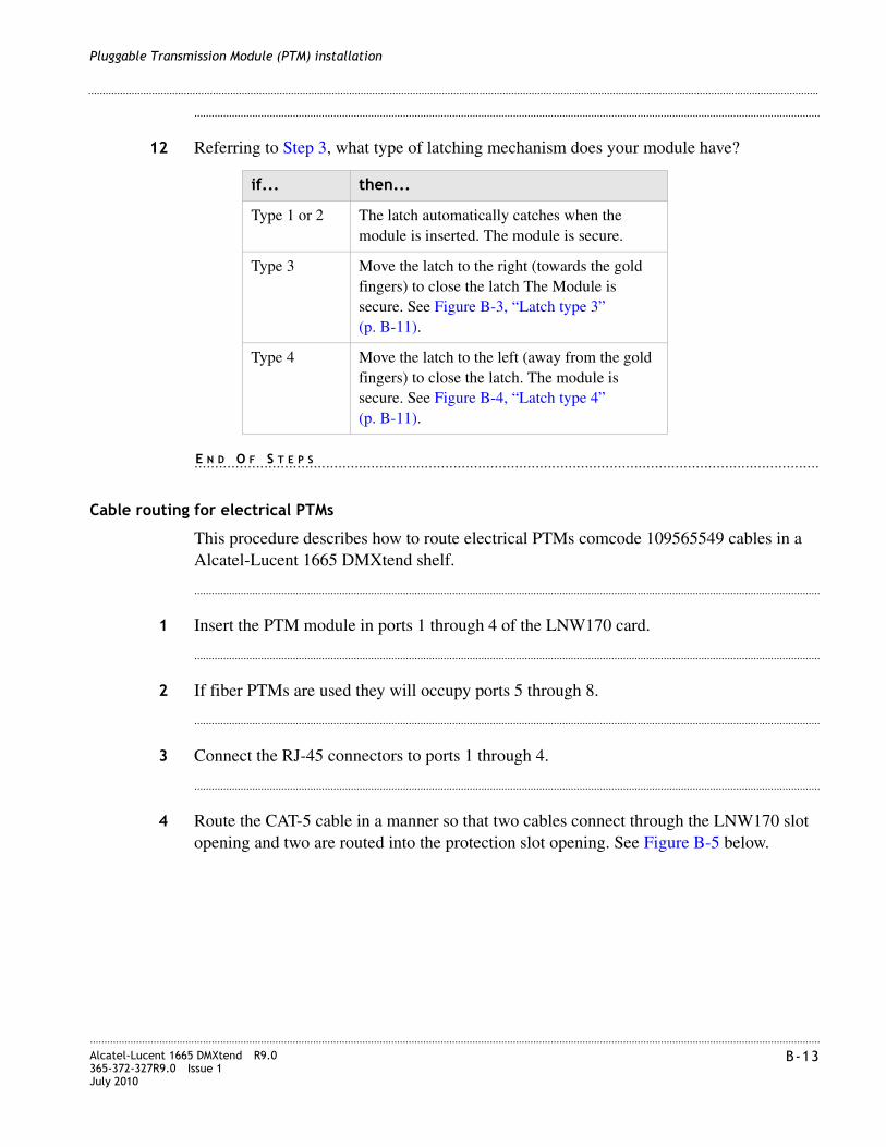
............................................................................................................................................................................................................................................................Alcatel-Lucent 1665 DMXtend R9.0365-372-327R9.0 Issue 1July 2010
B-13
............................................................................................................................................................................................................................................................
Pluggable Transmission Module (PTM) installation
........................................................................................................................................................................................................................
12 Referring to Step 3, what type of latching mechanism does your module have?
........................................................................................................................................................E N D O F S T E P S
Cable routing for electrical PTMs
This procedure describes how to route electrical PTMs comcode 109565549 cables in a Alcatel-Lucent 1665 DMXtend shelf.
........................................................................................................................................................................................................................
1 Insert the PTM module in ports 1 through 4 of the LNW170 card.
........................................................................................................................................................................................................................
2 If fiber PTMs are used they will occupy ports 5 through 8.
........................................................................................................................................................................................................................
3 Connect the RJ-45 connectors to ports 1 through 4.
........................................................................................................................................................................................................................
4 Route the CAT-5 cable in a manner so that two cables connect through the LNW170 slot opening and two are routed into the protection slot opening. See Figure B-5 below.
if... then...
Type 1 or 2 The latch automatically catches when the module is inserted. The module is secure.
Type 3 Move the latch to the right (towards the gold fingers) to close the latch The Module is secure. See Figure B-3, “Latch type 3” (p. B-11).
Type 4 Move the latch to the left (away from the gold fingers) to close the latch. The module is secure. See Figure B-4, “Latch type 4” (p. B-11).

............................................................................................................................................................................................................................................................B-14 Alcatel-Lucent 1665 DMXtend R9.0
365-372-327R9.0 Issue 1July 2010
............................................................................................................................................................................................................................................................
Pluggable Transmission Module (PTM) installation
Figure B-5 Electrical PTM routing
........................................................................................................................................................E N D O F S T E P S
C-1Alcatel-Lucent 1665 DMXtend R9.0365-372-327R9.0 Issue 1July 2010
............................................................................................................................................................................................................................................................
C Installing fiber connectors and LBOs
Overview
Purpose
This appendix provides procedures for installing and removing Line Build Out units (LBOs) and fiber connectors onto input and output ports found on the Alcatel-Lucent 1665 Data Multiplexer Extend (Alcatel-Lucent 1665 DMXtend) optical circuit packs.
Contents
This chapter provides information on the following topics:
Objectives
This appendix provides information to perform the following:
• Install and remove LC-type LBOs onto and from LC-type ports.
• Install and remove LC-type fiber connections.
Fiber cleaning
See Appendix A, “Fiber cleaning” for fiber cleaning information. Do not attempt to clean LBOs as they may be damaged by a cleaning attempt. Discard suspect LBOs and replace with a new unit.
LBOs C-2
Fiber connections C-4
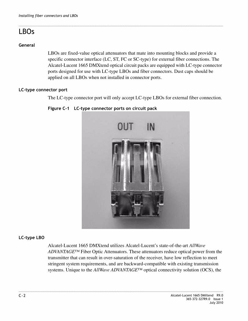
............................................................................................................................................................................................................................................................C-2 Alcatel-Lucent 1665 DMXtend R9.0
365-372-327R9.0 Issue 1July 2010
............................................................................................................................................................................................................................................................
Installing fiber connectors and LBOs
LBOs
General
LBOs are fixed-value optical attenuators that mate into mounting blocks and provide a specific connector interface (LC, ST, FC or SC-type) for external fiber connections. The Alcatel-Lucent 1665 DMXtend optical circuit packs are equipped with LC-type connector ports designed for use with LC-type LBOs and fiber connectors. Dust caps should be applied on all LBOs when not installed in connector ports.
LC-type connector port
The LC-type connector port will only accept LC-type LBOs for external fiber connection.
Figure C-1 LC-type connector ports on circuit pack
LC-type LBO
Alcatel-Lucent 1665 DMXtend utilizes Alcatel-Lucent’s state-of-the-art AllWave ADVANTAGE™ Fiber Optic Attenuators. These attenuators reduce optical power from the transmitter that can result in over-saturation of the receiver, have low reflection to meet stringent system requirements, and are backward-compatible with existing transmission systems. Unique to the AllWave ADVANTAGE™ optical connectivity solution (OCS), the

............................................................................................................................................................................................................................................................Alcatel-Lucent 1665 DMXtend R9.0365-372-327R9.0 Issue 1July 2010
C-3
............................................................................................................................................................................................................................................................
Installing fiber connectors and LBOs
new LC™ optic attenuators are designed to provide flat spectral loss across the full spectrum, allowing the attenuators to be used in the 1300-nm, 1400-nm, and 1500-nm bands.
Figure C-2 LC-type LBO
Assembly of LC-type LBO into LC block
The LC-type LBOs are installed into the LC-type connector by aligning the alignment key with the slot in the connector port and pushing the LBO into the port until it snaps into place.
Figure C-3 LC-type LBO inserted into LC-type connector port
Removal of LC-type LBO from LC block
The LC-type LBOs are removed from the LC-type connector port by depressing the tab to release the LBO and then pulling straight out.
ALIGNMENT KEY
SNAP-ACTION TAB
ALIGNMENTSLOT
15-dB LBO

............................................................................................................................................................................................................................................................C-4 Alcatel-Lucent 1665 DMXtend R9.0
365-372-327R9.0 Issue 1July 2010
............................................................................................................................................................................................................................................................
Installing fiber connectors and LBOs
Figure C-4 Removing LC-type LBO from LC-type connector port
Fiber connections
General
Alcatel-Lucent 1665 DMXtend uses AllWave ADVANTAGE™ Lightguide Jumpers, part of Alcatel-Lucent’s AllWave ADVANTAGE™ Optical Connectivity Solution (OCS). These jumpers contain a boot angled at 40 degrees, allowing the jumpers to dress appropriately into the fiber tray. The angled boot eliminates projection outside the front of the shelf assembly.
All fiber connectors should be cleaned and inspected before assembling into connector ports. See Appendix A, “Fiber cleaning”. Dust caps should be applied to all fiber connectors when not installed in a connector port.
LC-type connections
LC-type fiber connectors use a snap-action, lever-tab locking method to join the fiber connector to the port connector.
DEPRESS TABTO RELEASE LBO

............................................................................................................................................................................................................................................................Alcatel-Lucent 1665 DMXtend R9.0365-372-327R9.0 Issue 1July 2010
C-5
............................................................................................................................................................................................................................................................
Installing fiber connectors and LBOs
Figure C-5 LC-type fiber connector
The LC-type fiber connector is assembled onto an LC-type connector port of a circuit pack or LC-type LBO by aligning the alignment key with the slot in the connector port and pushing the connector into the port until it snaps into place.
The LC-type fiber connector is removed from a connector port by depressing the snap-action lever to disengage the fiber connector.
Figure C-6 LC-type fiber connection
ALIGNMENT KEY SNAP-ACTION TAB SNAP-ACTION LEVER
ALIGNMENTSLOT
DEPRESS LEVERTO RELEASE THESNAP-ACTION TAB

............................................................................................................................................................................................................................................................C-6 Alcatel-Lucent 1665 DMXtend R9.0
365-372-327R9.0 Issue 1July 2010
............................................................................................................................................................................................................................................................
Installing fiber connectors and LBOs
D-1Alcatel-Lucent 1665 DMXtend R9.0365-372-327R9.0 Issue 1July 2010
............................................................................................................................................................................................................................................................
D Backplane pin replacement
Overview
Purpose
This appendix provides information and the procedures used when a connector and/or pin on the Alcatel-Lucent 1665 Data Multiplexer Extend (Alcatel-Lucent 1665 DMXtend) backplane has been bent or broken.
Contents
This appendix provides information on the following topics:
Objectives
This appendix provides information and procedures to do the following:
• Identify a bent or broken pin
• Determine the correct replacement pin and pin kit
• Straighten bent pin
• Replace broken pins
Pin and connector background D-2
Repair kits and tools D-3
Simple repair methods D-4
Replacement methods D-5

............................................................................................................................................................................................................................................................D-2 Alcatel-Lucent 1665 DMXtend R9.0
365-372-327R9.0 Issue 1July 2010
............................................................................................................................................................................................................................................................
Backplane pin replacement
Pin and connector background
Description
This section describes the procedures for the repair/replacement of the press-fit connector pins used on the backplane of the Alcatel-Lucent 1665 DMXtend shelf. Trouble clearing procedures may lead you to inspect the backplane for damaged connectors.
Circuit packs are plugged into METRAL™ signal pin connectors which have been press-fit into the backplane. A plastic shroud is included with the connectors to protect the pins. The signal pin press-fit terminals in these connectors my be replaced individually if they have been damaged beyond simple repair methods.
D-subminiature connectors
Interface cabling to and from the Alcatel-Lucent 1665 DMXtend shelves is connected through D-Subminiature connectors which have been press-fit into the backplane. Should these connectors be damaged beyond simple repair methods, contact your next level of support for the replacement procedure.
RJ45 jacks
Interface cabling to and from the Alcatel-Lucent 1665 DMXtend shelves is connected through RJ45 connectors (jacks) which have been press-fit into the backplane. Should these jacks be damaged beyond simple repair methods, contact your next level of support for the replacement procedure.
Shelves and backplanes
The Alcatel-Lucent 1665 DMXtend has its connectors and terminal identifiers stenciled on the back surface for identification of location or position. The stenciling can only be seen when the back cover is removed.
Pins are identified by a column and row position on the backplane. D-Subminiature connectors are identified by their designation and J-number. All the METRAL™ pins used on the Alcatel-Lucent 1665 DMXtend shelves have the same tail length of 4.30 mm (0.169 in.).

............................................................................................................................................................................................................................................................Alcatel-Lucent 1665 DMXtend R9.0365-372-327R9.0 Issue 1July 2010
D-3
............................................................................................................................................................................................................................................................
Backplane pin replacement
Table D-1 show the location and type of METRAL™ pins on the Alcatel-Lucent 1665 DMXtend backplane.
Table D-1 Backplane locations of METRAL™ pins
Repair kits and tools
Repair kits
For the repair or replacement of METRAL™ signal pins, use one of the following repair kits:
• Berg Electronic MT370-01 Shelf Level Press-Fit Repair Kit
• IMDARC R-6004 Metral™ Pin Repair Kit - Comcode 407959881
This kit includes the tools, parts and instructions for repair and replacement of signal pins.
Replacement pins
Replacement pins are available. These pins are defined by the mating length extending beyond the inside of the plastic shroud and by their tail length for press-fitting into the backplane. The tail length includes a compliant press-fit section needed to achieve a gas-tight connection in four contact areas. All the METRAL™ pins used on the Alcatel-Lucent 1665 DMXtend shelves have the same tail length of 4.30 mm (0.169 in.).
Additional replacement signal pins may be ordered in packages of 100 by the part number shown in Table D-2, “Metral™ pins” (p. D-3).
Table D-2 Metral™ pins
Row Column TypeMating length (mm)
Tail length (mm)
001, 154, 156, 162 GND Signal Pin 5.75 4.30
001, 154, 156, 162 a, b, d, g Signal Pin 8.00 4.30
All others All others Signal Pin 5.75 4.30
TypeMatinglength (mm) Berg part #
Ground 5.75 88929-502
Signal Pin 5.75 88929-502
Signal Pin 8.00 88929-519

............................................................................................................................................................................................................................................................D-4 Alcatel-Lucent 1665 DMXtend R9.0
365-372-327R9.0 Issue 1July 2010
............................................................................................................................................................................................................................................................
Backplane pin replacement
Simple repair methods
Precautions
Proper ESD precautions must be followed.
Make sure that you have adequate space to access the backplane area and that you have good light sources so that you can see what you are doing.
Visual examination
Visually examine the connector pins to determine which pins may have been damaged and the degree of the damage. Pins that have been slightly bent may be carefully restored to their initial straight position. Examine both sides of the backplane to determine if the press-fit termination has been disturbed. These pins depend on an undisturbed interference fit between the terminal body and the plated-through hole in the backplane to create a reliable connection.
If the visual examination suggests that the connector pins are loose or are damaged beyond repair, replace the connector pin.
CAUTION
Equipment Damage/Personal Injury
These procedures should be done with the shelf out of service and powered down to ensure no further damage to the equipment or to the person doing the repair. If service cannot be removed or rerouted, contact your next level of support before proceeding.
CAUTION
ESD hazard

............................................................................................................................................................................................................................................................Alcatel-Lucent 1665 DMXtend R9.0365-372-327R9.0 Issue 1July 2010
D-5
............................................................................................................................................................................................................................................................
Backplane pin replacement
METRAL™ backplane pins
Follow the instructions and use the tools provided in the MT370-01 Shelf Level Press-Fit Repair Kit to straighten METRALTM pins which may have been bent out of position.
Guide pins and keying pins
If a stainless steel guide pin or keying pin has been bent out of alignment, attempts to straighten it may damage the backplane. The recommended alternative is to replace the bent pin.
D-subminiature pins
The D-Subminiature connectors on the Alcatel-Lucent 1665 DMXtend backplane are all of the receptacle type. These connectors are designated as jacks and not as plugs. The individual connector terminals are protected somewhat by the molded plastic insert inside the connector shell. It is unlikely that these terminals would be bent in the manner that the exposed pin terminals of a plug might be bent. The damage concern for these receptacle terminals is that they may be “crushed” or otherwise distorted out of shape. Attempts to “straighten” these terminals may result in fracturing them. If a receptacle terminal has been damaged to the extent that the mating plug connector cannot be connected, then the recommended alternative is to replace the entire backplane.
RJ45 jacks
The RJ45 connectors (jacks) are press-fitted into the Alcatel-Lucent 1665 DMXtend backplane. Should these jacks be damaged beyond simple repair methods, contact your next level of support for the replacement procedure.
Replacement methods
Background
Connector pins are designed to withstand a considerable removal force. An impact-type tool is used to generate a controlled removal force. Similarly, proper insertion of a press-fit connector pin is done with an impact-type tool to control the insertion forces and not damage adjacent pins.
CAUTION
Equipment Damage
This is a delicate procedure. Take your time to gently straighten the pin in several small steps. Large movements may damage adjacent pins.

............................................................................................................................................................................................................................................................D-6 Alcatel-Lucent 1665 DMXtend R9.0
365-372-327R9.0 Issue 1July 2010
............................................................................................................................................................................................................................................................
Backplane pin replacement
Precautions
Read the following Important statements before proceeding:
Note: Any press-fit connector pin may be removed and replaced one time in the Alcatel-Lucent 1665 DMXtend backplane. A second removal and replacement in the same plated-through hole may not meet the long-term reliability objectives. If a replacement is needed for a previously replaced connector pin, contact your next level of support before proceeding.
Note: Protect the surrounding area from any debris which may be generated during the pin removal and replacement.
Steps
........................................................................................................................................................................................................................
1 Verify that the problem cannot be fixed using a simple repair procedure.
........................................................................................................................................................................................................................
2 Secure the proper tool kit.
........................................................................................................................................................................................................................
3 Read the tool kit instructions before beginning.
........................................................................................................................................................................................................................
4 Plan and write out a “Method of Procedure” specific to your location.
........................................................................................................................................................................................................................
5 Follow the instructions provided to remove the damaged pin.
........................................................................................................................................................................................................................
6 Install the replacement pin.
........................................................................................................................................................................................................................
7 Verify that the new pin is securely in the backplane.
........................................................................................................................................................................................................................
8 If the replacement is not successful, contact your next level of support.
........................................................................................................................................................E N D O F S T E P S

............................................................................................................................................................................................................................................................Alcatel-Lucent 1665 DMXtend R9.0365-372-327R9.0 Issue 1July 2010
D-7
............................................................................................................................................................................................................................................................
Backplane pin replacement
Guide and keying pin procedure
If it becomes necessary to replace Guide or Keying Pins, contact your next level of support for tooling, replacement parts and detailed replacement procedures. The replacements will need to installed with screws and washers.
D-subminiature pin procedure
If it becomes necessary to replace either the D-Subminiature pins or connector, contact your next level of support for detailed replacement procedures.
RJ45 jacks
If it becomes necessary to replace a RJ45 connector, contact your next level of support for the replacement procedure.

............................................................................................................................................................................................................................................................D-8 Alcatel-Lucent 1665 DMXtend R9.0
365-372-327R9.0 Issue 1July 2010
............................................................................................................................................................................................................................................................
Backplane pin replacement

E-1Alcatel-Lucent 1665 DMXtend R9.0365-372-327R9.0 Issue 1July 2010
............................................................................................................................................................................................................................................................
E Fiber labeling
Overview
Purpose
This appendix describes the labeling of the fiber.
Contents
This chapter contains the following:
Fiber description
Fibers
There are three different types of single-mode fiber used with the Alcatel-Lucent 1665 Data Multiplexer Extend (Alcatel-Lucent 1665 DMXtend), simplex blue fiber, simplex yellow fiber, and the customer's fiber, and two types of multi-mode fiber used with the Alcatel-Lucent 1665 DMXtend, multi-mode simplex gray fiber and the customer's multi-mode fiber.
Blue fiber
Blue fiber is made up of a single blue colored fiber equipped with LC connectors at both ends. It is referred to as Simplex LC Blue Fiber. The Blue Fibers are custom cut to length for their application. The length is given on the protection boot of the LC connector.
Fiber description E-1
Fiber labels E-3

............................................................................................................................................................................................................................................................E-2 Alcatel-Lucent 1665 DMXtend R9.0
365-372-327R9.0 Issue 1July 2010
............................................................................................................................................................................................................................................................
Fiber labeling
Gray fiber
Blue fiber is made up of a multi-gray colored fiber equipped with LC connectors at both ends. It is referred to as Multi-mode LC Gray Fiber. The Gray Fibers are custom cut to length for their application. The length is given on the protection boot of the LC connector.
Yellow fiber
Simplex fibers are Yellow in color and come in six different lengths (15, 20, 25, 30, 35 and 50 feet), as well as custom lengths.
Outside fiber
Outside fiber is the fiber connecting the Customer equipment to the Alcatel-Lucent 1665 DMXtend. Depending on the customers specifications, these fibers may be any combination of SC, FC, or ST connectors. The length of these fibers depends on the system interface setup. This fiber is usually referred to as the Outside Bay or Plant Fiber.
Outside Bay Fiber management should be specified by the customer. It is beyond the scope of this document to specify the route or dressings that the fiber should take once it leaves the equipment bays.
............................................................................................................................................................................................................................................................Alcatel-Lucent 1665 DMXtend R9.0365-372-327R9.0 Issue 1July 2010
E-3
............................................................................................................................................................................................................................................................
Fiber labeling
Precautions
Single-mode fiber testing requirements
All fibers should be tested after they are installed as follows:
• All fibers should be tested after installation, but prior to turn-up
• Before fibers are tested, they should be labeled properly and all cable tags should be removed.
• A 1310-nm or 1550-nm test source and an ITE# 7116 (or equivalent) optical power meter should be used to perform all tests.
• The light source shall first be measured for a reference point/baseline.
• No fiber jumper may have a measured loss of more than 2 dB.
Fiber labels
Introduction
If pre-printed labels are not available, use a label-maker to create labels for each end of each fiber. The label should include:
• Rack location
• Circuit pack
• Port
• Direction (IN,OUT)
Labeling the fibers
To apply the labels to the connectors, use the following procedure.
........................................................................................................................................................................................................................
1 Remove the appropriate label from the backing sheet or the label maker.
CAUTION
Fiber Damage
Fiber is constructed of glass and should be treated with care. It should not be pulled or stretched. This could cause damage to the fiber or the fiber connector.
Fiber should not be bent in a radius of less than 1-1/2”.

............................................................................................................................................................................................................................................................E-4 Alcatel-Lucent 1665 DMXtend R9.0
365-372-327R9.0 Issue 1July 2010
............................................................................................................................................................................................................................................................
Fiber labeling
........................................................................................................................................................................................................................
2 Apply the label to the strain relief boot, close to the body of the LC connector.
........................................................................................................................................................................................................................
3 Adhere the end of the label with the printed text first.
........................................................................................................................................................................................................................
4 The label must be oriented perpendicular to the main axis of the connector.
........................................................................................................................................................................................................................
5 Wrap the label around the boot so that the second wrap is directly on top of the first wrap. (The label will wrap around the boot approximately two times). The text is printed diagonally on the label so that it can be read when applied the correct way.
Note: Do not apply the label diagonally to the boot. The label must wrap directly on top of itself for the adhesive to work.
........................................................................................................................................................E N D O F S T E P S

1-1Alcatel-Lucent 1665 DMXtend R9.0365-372-327R9.0 Issue 1July 2010
............................................................................................................................................................................................................................................................
Glossary
............................................................................................................................................................................................................................................................
A
ABNAbnormal (status condition)
ACOAlarm Cutoff
ACO/SWAlarm Cutoff and Test
ADMAdd/Drop Multiplexer
AGNEAlarm Gateway Network Element
AISAlarm Indication Signal
AMIAlternate Mark Inversion
ANSIAmerican National Standards Institute
APSAutomatic Protection Switch
ARMAccess Resource Manager
AS&CAlarm, Status, and Control
ASCIIAmerican Standard Code for Information Interchange
ASN.1Abstract Syntax Notation 1
ASNEAlarm Server Network Element
ATMAsynchronous Transfer Mode

............................................................................................................................................................................................................................................................1-2 Alcatel-Lucent 1665 DMXtend R9.0
365-372-327R9.0 Issue 1July 2010
............................................................................................................................................................................................................................................................
Glossary
AutoAutomatic
AUXCTLAuxiliary Control
............................................................................................................................................................................................................................................................
B
B3ZSBipolar 3-Zero Substitution
B8ZSBipolar 8-Zero Substitution
BDFBBattery Distribution and Fuse Bay
BERBit Error Ratio
BIPBit Interleaved Parity
BITSBuilding Integrated Timing Supply
BRIBasic Rate Interface
............................................................................................................................................................................................................................................................
C
CCClear Channel
CCITTInternational Telephone and Telegraph Consultative Committee
CEVControlled Environment Vault
CD-ROMCompact Disk, Read-Only Memory
CDTUChannel and Drop Test Unit
CITCraft Interface Terminal
CLFCarrier Line Failure Status

............................................................................................................................................................................................................................................................Alcatel-Lucent 1665 DMXtend R9.0365-372-327R9.0 Issue 1July 2010
1-3
............................................................................................................................................................................................................................................................
Glossary
CLKClock
CMISECommon Management Information Service Element
CMOSComplementary Metal Oxide Semiconductor
CMTSCable Modem Termination System
COCentral Office
CPCircuit Pack
CPECustomer Premises Equipment
CRCritical (alarm status)
CSACarrier Serving Area
CSUChannel Service Unit
CS&OCustomer Support and Operations
CVCoding Violation
CVFECoding Violation Far End
............................................................................................................................................................................................................................................................
D
DCCData Communications Channel
DCEData Communications Equipment
DEMUXDemultiplexer
DLCDigital Loop Carrier

............................................................................................................................................................................................................................................................1-4 Alcatel-Lucent 1665 DMXtend R9.0
365-372-327R9.0 Issue 1July 2010
............................................................................................................................................................................................................................................................
Glossary
DPLLDigital Phase-Locked Loop
DRIDual Ring Interworking
DS1Digital Signal Level 1
DS3Digital Signal Level 3
DSLAMDigital Subscriber Line Access Multiplexer
DSNEDirectory Services Network Element
DSXDigital Cross-Connect Panel
DTDistant Terminal
DTEData Terminating Equipment
............................................................................................................................................................................................................................................................
E
EC-1Electrical Carrier Level 1
ECIEquipment Catalog Item
EEPROMElectrically-Erasable Programmable Read-Only Memory
EIAElectronic Industries Association
EMCElectromagnetic Compatibility
EMIElectromagnetic Interference
EOOFExcessive Out of Frame
EPROMErasable Programmable Read-Only Memory

............................................................................................................................................................................................................................................................Alcatel-Lucent 1665 DMXtend R9.0365-372-327R9.0 Issue 1July 2010
1-5
............................................................................................................................................................................................................................................................
Glossary
EQEquipped (memory administrative state)
ESErrored Seconds
ESDElectrostatic Discharge
ESFExtended Super Frame
ESTEnvironmental Stress Testing
............................................................................................................................................................................................................................................................
F
FCCFederal Communications Commission
FDDIFiber Distribution Data Interface
FEFar End
FE ACTYFar End Activity
FEBEFar End Block Error
FE IDFar End Identification
FEPROMFlash EPROM
FERFFar End Receive Failure
FE SELFar End Select
FITFailures in 10-9 hours of operation.
............................................................................................................................................................................................................................................................
G
GbEGigabit Ethernet

............................................................................................................................................................................................................................................................1-6 Alcatel-Lucent 1665 DMXtend R9.0
365-372-327R9.0 Issue 1July 2010
............................................................................................................................................................................................................................................................
Glossary
GNEGateway Network Element
GRTelcordia Technologies General Requirement
GTPGeneral Telemetry Processor
GTSIPGlobal Technical Support Information Platform
GUIGraphical User Interface
............................................................................................................................................................................................................................................................
H
HECIHumans Equipment Catalog Item
............................................................................................................................................................................................................................................................
I
ICInternal Clock
IDIdentifier
IECInternational Electrotechnology Commission
IMFInfant Mortality Factor
INCIncoming Status
I/OInput/Output
IPInternet Protocol
IRIntermediate Reach
ISIn Service
ISCIIntershelf control Interface

............................................................................................................................................................................................................................................................Alcatel-Lucent 1665 DMXtend R9.0365-372-327R9.0 Issue 1July 2010
1-7
............................................................................................................................................................................................................................................................
Glossary
ISIIntershelf Interface
ISDNIntegrated Services Digital Network
ISOInternational Standards Organization
ISPInternet Service Provider
IVHSIntelligent Vehicle Highway System
............................................................................................................................................................................................................................................................
L
LANLocal Area Network
LAPDLink Access Procedure "D"
LBOLine Build Out
LCNLocal Communications Network
LECLocal Exchange Carrier
LEDLight-Emitting Diode
LOFLoss of Frame
LOPLoss of Pointer
LOSLoss of Signal
LRLong Reach
LSLow Speed

............................................................................................................................................................................................................................................................1-8 Alcatel-Lucent 1665 DMXtend R9.0
365-372-327R9.0 Issue 1July 2010
............................................................................................................................................................................................................................................................
Glossary
............................................................................................................................................................................................................................................................
M
MDMediation Device
MJMajor Alarm
MMMultimode
MMLhuMan-Machine Language
MNMinor Alarm
MPEGMoving Picture Experts Group
MSDTMulti-Services Distant Terminal
MTBFMean Time Between Failures
MTBMAMean Time Between Maintenance Activities
MultMultipling
MUXMultiplex
MXBIUMultiplexer and Backplane Interface Unit
............................................................................................................................................................................................................................................................
N
NENear End
NENetwork Element
NE ACTYNear-End Activity
NEBSNetwork Equipment-Building System

............................................................................................................................................................................................................................................................Alcatel-Lucent 1665 DMXtend R9.0365-372-327R9.0 Issue 1July 2010
1-9
............................................................................................................................................................................................................................................................
Glossary
nmNanometer (10-9 meters)
NMANetwork Monitoring and Analysis
NMONNot Monitored (provisioning state)
NRZNonreturn to Zero
NARTACLucent North American Regional Technical Assistance Center call 1-866-LUCENT8 (866-582-3688): Prompt 1
NNINetwork-Network Interface
NSANot Service Affecting
NSAPNetwork Services Access Point
NTFNo Trouble Found
............................................................................................................................................................................................................................................................
O
OAM&POperations, Administration, Maintenance, and Provisioning
OC-1Optical Carrier Level 1 Signal (51.84 Mb/s)
OC-3Optical Carrier Level 3 Signal (155 Mb/s)
OC-12Optical Carrier Level 12 Signal (622 Mb/s)
OC-48Optical Carrier Level 48 Signal
OLIUOptical Line Interface Unit
OOFOut of Frame
OOLOut of Lock

............................................................................................................................................................................................................................................................1-10 Alcatel-Lucent 1665 DMXtend R9.0
365-372-327R9.0 Issue 1July 2010
............................................................................................................................................................................................................................................................
Glossary
OPS/INEOperations System/Intelligent Network Element
OSOperations System
OSGNEOperations System Gateway Network Element
OSIOpen Systems Interconnection
OSMINEOperations Systems Modifications for the Integration of Network Elements
OSPOutside Plant
............................................................................................................................................................................................................................................................
P
P-bitPerformance Bit
PCPersonal Computer
PCUPower Conversion Unit
PIDProgram Identification
PINFETPositive Intrinsic Negative Field Effect Transistor
PJCPointer Justification Count
PLLPhase-Locked Loop
PMPerformance Monitoring
PMNPower Minor Alarm
POHPath Overhead
POPPoints of Presence
............................................................................................................................................................................................................................................................Alcatel-Lucent 1665 DMXtend R9.0365-372-327R9.0 Issue 1July 2010
1-11
............................................................................................................................................................................................................................................................
Glossary
POTSPlain Old Telephone Service
PRMPerformance Report Message
PROTNProtection
PRSPrimary Reference Source
PSUPower Supply Unit
PTMPluggable Transmission Module
PVCPermanent Virtual Circuit
PWRPower
............................................................................................................................................................................................................................................................
R
RAMRandom Access Memory
RPPReliability Prediction Procedure (described in Telcordia Technologies TR-NWT-00032)
RTRemote Terminal
RZReturn to Zero
............................................................................................................................................................................................................................................................
S
SAService Affecting
SCADASupervisory Control and Data Acquisition
SDSignal Degrade
SDHSynchronous Digital Hierarchy

............................................................................................................................................................................................................................................................1-12 Alcatel-Lucent 1665 DMXtend R9.0
365-372-327R9.0 Issue 1July 2010
............................................................................................................................................................................................................................................................
Glossary
SEFSSeverely Errored Frame Seconds
SEOSingle-Ended Operations
SESSeverely Errored Seconds
SFSuper Frame (format for DS1 signal)
SFP
Small Form Programable.
SIDSystem Identification
SLAService Level Agreements
SLIMSubscriber Loop Interface Module
SMSingle Mode
SONETSynchronous Optical NETwork
SPESynchronous Payload Envelope
SQUSync Quality Unknown
SRDSoftware Release Description
STS, STS-nSynchronous Transport Signal
STMSynchronous Transfer Mode
STS-1 SPESTS-1 Synchronous Payload Envelope
STS-3cSynchronous Transport Level 3 Concatenated Signal
STS-12cSynchronous Transport Level 12 Concatenated Signal

............................................................................................................................................................................................................................................................Alcatel-Lucent 1665 DMXtend R9.0365-372-327R9.0 Issue 1July 2010
1-13
............................................................................................................................................................................................................................................................
Glossary
SYSCTLSystem Controller (circuit pack)
............................................................................................................................................................................................................................................................
T
T1X1 and T1M1The ANSI committees responsible for telecommunications standards
TATelcordia Technologies Technical Advisory
TABSTelemetry Asynchronous Byte Serial (Protocol)
TARPTarget ID Address Resolution Protocol
TCAThreshold-Crossing Alert
TCP/IPTransmission Control Protocol/Internet Protocol
TCVCXOTermperature-Compensated Voltage-Controlled Crystal Oscillator
TDMTime Division Multiplexing
TIDTarget Identifier
TL1Transaction Language 1
TLBTiming Looped Back
TOPTask Oriented Practice
TRTelcordia Technologies Technical Requirement
TSATime Slot Assignment
TSITime Slot Interchange
TSOTechnical Support Organization

............................................................................................................................................................................................................................................................1-14 Alcatel-Lucent 1665 DMXtend R9.0
365-372-327R9.0 Issue 1July 2010
............................................................................................................................................................................................................................................................
Glossary
............................................................................................................................................................................................................................................................
U
UASUnavailable Seconds
UNIUser Network Interface
UOCUniversal Optical Connector
UPD/INITUpdate/Intialize
UPSRUnidirectional Path Switched Rings
............................................................................................................................................................................................................................................................
V
VFVoice Frequency
VLANVirtual Local Area Network
VLSIVery Large Scale Integration
VMViolation Monitor
VMRViolation Monitor and Removal
VoIPVoice over Internet Protocol
VONUVirtual Optical Network Unit
VPNVirtual Private Network
VTVirtual Tributary
VT1.5Virtual Tributary 1.5 (1.728 Mb/s)
VT-GVirtual Tributary Group

............................................................................................................................................................................................................................................................Alcatel-Lucent 1665 DMXtend R9.0365-372-327R9.0 Issue 1July 2010
1-15
............................................................................................................................................................................................................................................................
Terms and definitions
............................................................................................................................................................................................................................................................
W
WANWide Area Network
Terms and definitions0x1Set up using unswitched cross connections on UPSR Ring Interfaces.
1+1The 1+1 protection switching architecture protects against failures of the optical transmit/receive equipment and their connecting fiber facility. One bidirectional interface (two fibers plus associated OLIUs on each end) is designated "service," and the other is designated "protection." In each direction, identical signals are transmitted on the service and protection lines ("dual-fed"). The receiving equipment monitors the incoming service and protection lines independently, and selects traffic from one line (the "active" line) based on performance criteria and technician/OS control. In 1+1 both service and protection lines could be active at the same time (service in one direction, protection in the other).
1xN, 1x11xN protection switching pertains to circuit pack protection that provides a redundant signal path through the Alcatel-Lucent 1665 DMXtend (it does not cover protection switching of an optical facility; se "1+1"). In 1xN switching, a group of N service circuit packs share a single spare protection circuit pack. 1x1 is a special case of 1xN, with N=1. In 1x1 only one is active at a time.
............................................................................................................................................................................................................................................................
A
ActiveActive identifies a 1+1 protected OC-N line which is currently selected by the receiver at either end as the payload carrying signal or a 1x1 or 1xN protected circuit pack that is currently carrying service. (See Standby).
AGNE - Alarm Gateway Network ElementA defined NE in an alarm group through which members of the alarm group exchange information.
AIS - Alarm Indication SignalA code transmitted downstream in a digital network that shows that an upstream failure has been detected and alarmed.
AMI - Alternate Mark InversionA line code that employs a ternary signal to convey binary digits, in which successive binary ones are represented by signal elements that are normally of alternating, positive and negative polarity but equal in amplitude, and in which binary zeros are represented by signal elements that have zero amplitude.

............................................................................................................................................................................................................................................................1-16 Alcatel-Lucent 1665 DMXtend R9.0
365-372-327R9.0 Issue 1July 2010
............................................................................................................................................................................................................................................................
Terms and definitions
ASCII - American Standard Code for Information Interchange A standard 8-bit code used for exchanging information among data processing systems and associated equipment.
AutoOne possible state of a service interface port. In this state, the port will automatically be put "in service" if a good incoming signal is detected on the port.
Automatic Protection SwitchA feature that allows another synchronization source to be automatically selected and the synchronization source provisioning to be automatically reconfigured in the event of a synchronization source failure or network synchronization change, for example, a fiber cut.
Available TimeIn performance monitoring, the 1-second intervals.
............................................................................................................................................................................................................................................................
B
B3ZS - Bipolar 3-Zero SubstitutionA line coding method that replaces a string of three zeros with a sequence of symbols having some special characteristic.
B8ZS - Bipolar 8-Zero SubstitutionA line coding method that replaces a string of eight zeros with a sequence of symbols having some special characteristic.
Backbone RingA host ring.
BER - Bit Error RatioThe ratio of bits received in error to the total bits sent.
BIP - Bit Interleaved Parity A method of error monitoring over a specified number of bits, that is BIP-3 or BIP-8.
BITS - Building Integrated Timing Supply A single clock that provides all the DS1 and DS0 synchronization references required by clocks in a building.
BroadbandAny communications channel with greater bandwidth than a voice channel; sometimes used synonomously with wideband. Also refers to signals at the DS3 (44.736 Mb/s) and higher. Wideband refers to lower rates (i.e. DS1, VT1.5, etc.).
............................................................................................................................................................................................................................................................
C
CC - Clear ChannelA provisionable mode for the DS3 output that causes parity violations not to be monitored or corrected before the DS3 signal is encoded.

............................................................................................................................................................................................................................................................Alcatel-Lucent 1665 DMXtend R9.0365-372-327R9.0 Issue 1July 2010
1-17
............................................................................................................................................................................................................................................................
Terms and definitions
CCITT - International Telephone and Telegraph Consultative CommitteeAn international advisory committee under United Nations’ sponsorship that has composed and recommended for adoption worldwide standards for international communications. Recently changed to the International Telecommunications Union Telecommunications Standards Sector (ITU-TSS).
ChannelA logical signal within a port. For example, for an EC-1 port, there is one STS-1 channel and sometimes 28 VT1.5 channels. See Port.
Channel State ProvisioningA feature that allows a user to suppress reporting of alarms and events during provisioning by supporting multiple states (automatic, in-service and not monitored) for VT1.5 and STS-1 channels. See Port State Provisioning.
CV - Coding ViolationA performance monitoring parameter.
CVFE - Coding Violation Far-EndAn indication returned to the transmitting terminal that an errored block has been detected at the receiving terminal.
............................................................................................................................................................................................................................................................
D
DACS III-2000Digital Access and Cross-Connect System that provides clear channel switching at either the DS3 or the STS-1 rates, eliminating the need for manual DSXs.
DACS IV-2000Digital Access and Cross-Connect System that provides electronic DS3/STS-1 or DS1/VT1.5 cross-connect capability, eliminating the need for manual DSXs.
DCC - Data Communications ChannelThe embedded overhead communications channel in the SONET line. It is used for end-to-end communications and maintenance. It carries alarm, control, and status information between network elements in a SONET network.
DCE - Data Communications EquipmentIn a data station, the equipment that provides the signal conversion and coding between the data terminal equipment (DTE) and the line. The DCE may be separate equipment or an integral part of the DTE or of intermediate equipment. A DCE may perform other functions usually performed at the network end of the line.
DDM-2000Lucent’s first generation SONET multiplexers that multiplex DS1, DS3, or EC-1 inputs into EC-1, OC-1, OC-3, or OC-12 outputs.
Default ProvisioningThe parameter values that are preprogrammed as shipped from the factory.

............................................................................................................................................................................................................................................................1-18 Alcatel-Lucent 1665 DMXtend R9.0
365-372-327R9.0 Issue 1July 2010
............................................................................................................................................................................................................................................................
Terms and definitions
DemultiplexingA process applied to a multiplexed signal for recovering signals combined within it and for restoring the distinct individual channels of these signals.
DEMUX - DemultiplexerThe DEMUX direction is from the fiber toward the DSX.
Digital MultiplexerEquipment that combines time-division multiplexing several digital signals into a single composite digital signal.
DRI - Dual Ring InterworkingTwo ring networks interconnected at two common nodes.
Drop and ContinueA technique that allows redundant signal appearances at two central offices in a DRI network, allowing protection against central office failures.
DS1Digital Signal Level 1 (1.544 Mb/s).
DS1(28) Circuit PackThe DS1(28) circuit pack interfaces to the DSX-1 panel.
DS3Digital Signal Level 3 (44.736 Mb/s).
DS3/EC-1 Circuit PackThe DS3/EC-1 circuit pack interfaces to the DSX-3 panel.
DSn - Digital Signal Rate nOne of the possible digital signal rates at Alcatel-Lucent 1665 DMXtend interfaces: DS1 (1.544 Mb/s) or DS3 (44.736 Mb/s).
DSX - Digital Cross-Connect PanelA panel designed to interconnect to equipment that operates at a designated rate. For example, a DSX-3 interconnects equipment operating at the DS3 rate.
DTE - Data Terminating EquipmentThat part of a data station that serves as a data source (originates data for transmission), a data sink (accepts transmitted data) or both.
Dual HomingA network topology in which two Alcatel-Lucent 1665 DMXtends serve as hosts supporting up to 8 OC-3 rings or 4 OC-12 rings. Each OC-3 and OC-12 ring is interconnected between the two separate hosts.

............................................................................................................................................................................................................................................................Alcatel-Lucent 1665 DMXtend R9.0365-372-327R9.0 Issue 1July 2010
1-19
............................................................................................................................................................................................................................................................
Terms and definitions
............................................................................................................................................................................................................................................................
E
EC-1, EC-n - Electrical CarrierThe basic logical building block signal with a rate of 51.840 Mb/s for an EC-1 signal and a rate of n times 51.840 Mb/s for an EC-n signal. An EC-1 signal can be built in two ways: A DS1 can be mapped into a VT1.5 signal and 28 VT1.5 signals multiplexed into an EC-1 (VT1.5 based EC-1) or a DS3 can be mapped directly into an EC-1 (DS3 based EC-1).
ECI - Equipment Catalog ItemThe bar code number on the faceplate of each circuit pack used by some inventory systems.
ES - Errored SecondsA performance monitoring parameter.
ESF - Extended Super FrameThe format for a DS1 signal.
............................................................................................................................................................................................................................................................
F
FE - Far EndAny other network element in a maintenance subnetwork other than the one the user is at or working on. Also called remote.
FE ACTY - Far End ActivityAn LED on the SYSCTL circuit pack faceplate.
FEBE - Far End Block ErrorAn indication returned to the near-end transmitting node that an errored block has been detected at the far end.
FEPROM - Flash EPROMNonvolatile Electrically-erasable Programmable Read-Only Memory.
FERF - Far End Receive FailureAn indication returned to the transmitting terminal that the receiving terminal has detected an incoming section failure.
FE SEL - Far End SelectAn LED on the faceplate of the SYSCTL circuit pack.
FITFailures in 10-9 hours of operation.
Free RunningAn operating condition of a clock in which its local oscillator is not locked to an internal synchronization reference and is using no storage techniques to sustain its accuracy.
FT-2000Lucent’s SONET OC-48 Lightwave System.
............................................................................................................................................................................................................................................................1-20 Alcatel-Lucent 1665 DMXtend R9.0
365-372-327R9.0 Issue 1July 2010
............................................................................................................................................................................................................................................................
Terms and definitions
Function UnitRefers to any one of a number of different circuit packs that can reside in the A/B, D, or G function unit slots on the Alcatel-Lucent 1665 DMXtend.
............................................................................................................................................................................................................................................................
G
GNE - Gateway Network ElementA network element that has an active X.25 link. Can also be a DSNE.
............................................................................................................................................................................................................................................................
H
Hairpin RoutingA cross-connection between function units (inter-function unit). For example, function unit C to function untis A, B, or D. Also, a cross-connection within the same function unit (intra-function unit). Cross-connections go through Main, but no bandwidth or time slots are taken from the backbone ring. Eliminates need for another shelf.
HoldoverAn operating condition of a network element in which its local oscillator is not locked to any synchronization reference but is using storage techniques to maintain its accuracy with respect to the last known frequency comparison with a synchronization reference.
............................................................................................................................................................................................................................................................
I
IC - Internal ClockUsed in synchronization messaging.
IDSee shelf ID and site ID.
IR - Intermediate ReachA term used to describe distances of 15 to 40 km between optical transmitter and receiver without regeneration. See long reach.
IS - In ServiceOne possible state of a DS1, DS3, or EC-1 port. Other possible states are "auto" (automatic) and "nmon" (not monitored).
............................................................................................................................................................................................................................................................
J
JitterTiming jitter is defined as short-term variations of the significant instants of a digital signal from their ideal positions in time.

............................................................................................................................................................................................................................................................Alcatel-Lucent 1665 DMXtend R9.0365-372-327R9.0 Issue 1July 2010
1-21
............................................................................................................................................................................................................................................................
Terms and definitions
............................................................................................................................................................................................................................................................
L
LBO - Line Build OutAn equalizer network between the Alcatel-Lucent 1665 DMXtend and the DSX panel. It guarantees the proper signal level and shape at the DSX panel.
LED - Light Emitting DiodeUsed on a circuit pack faceplate to show failure (red) or service state. It is also used to show the alarm and status condition of the system.
Line TimingThe capability to directly derive clock timing from an incoming OC-N signal while providing theuser the capability to provision whether switching to an alternate OC-N from a different source (as opposed to entering holdover) will occur if the OC-N currently used as the timing reference for that NE becomes unsuitable as a reference. For example, intermediate nodes in a linear network are line timed. See Loop Timing.
LocalSee Near-End.
Locked Cross-ConnectionThis is a variation of the ring cross-connection that allows the user to lock the path selector to a specified rotation of the ring. Any signal received from the other rotation of the ring is ignored.
LOF - Loss of FrameA failure to synchronize to an incoming signal.
Loop TimingLoop timing is a special case of line timing. It applies to NEs that have only one OC-N interface. For example, terminating nodes in a linear network are loop timed. See Line Timing.
LOP - Loss of PointerA failure to extract good data from an STS-1 payload.
LOS - Loss of SignalThe complete absence of an incoming signal.
LR - Long ReachA term used to describe distances of 40 km or more between optical transmitter and reciever without regeneration. See Intermediate Reach.
............................................................................................................................................................................................................................................................
M
MainThe two slots (M-1 and M-2) on the Alcatel-Lucent 1665 DMXtend shelf in which the OC-3 or OC-12 main OLIU circuit packs are installed.
Midspan MeetThe capability to interface between two lightwave terminals of different vendors. This applies to high-speed optical interfaces.

............................................................................................................................................................................................................................................................1-22 Alcatel-Lucent 1665 DMXtend R9.0
365-372-327R9.0 Issue 1July 2010
............................................................................................................................................................................................................................................................
Terms and definitions
MultiplexingThe process of combining several distinct digital signals into a single composite digital signal.
Mult - MultiplingThe cascading of signals in a bay. In the MULT mode, the DS1 external reference can be cascaded to other shelves in a bay using Mult cables. Normally starting with the bottom shelf (Number 1) and working towards the top of the bay.
............................................................................................................................................................................................................................................................
N
NE - Near EndThe network element the user is at or working on. Also called local.
NE - Network ElementThe basic building block of a telecommunications equipment within a telecommunication network that meets SONET standards. Typical internal attributes of a network element include: onr or more high- and low-speed transmission ports, built-in intelligence, synchronization and timing capability, and access interfaces for use by technicians and/or operation systems. In addition, a network element may also include a time slot interchanger.
NE ACTY - Near End ActivityAn LED on the faceplate of the SYSCTL circuit pack.
NMA - Network Monitoring and AnalysisAn operations system designed by Telcordia Technologies which is used to monitor network facilities.
NMON - Not MonitoredA provisioning state for equipment that is not monitored or alarmed.
NodeIn SONET, a node is a line terminating element.
Non-RevertiveA protection switching mode in which, after a protection switch occurs, the equipment remains in its current configuration after any failure conditions that caused a protection switch to occur clear or after any external switch commands are reset. See Revertive.
NSAP - Network Services Access PointAn address that identifies a network element. Used for maintenance subnetwork communication using the OSI protocol.
............................................................................................................................................................................................................................................................
O
OC, OC-n - Optical CarrierThe optical signal that results from an optical inversion of an STS signal; that is, OC-1 from STS-1 and OC-n from STS-n.
............................................................................................................................................................................................................................................................Alcatel-Lucent 1665 DMXtend R9.0365-372-327R9.0 Issue 1July 2010
1-23
............................................................................................................................................................................................................................................................
Terms and definitions
OC-1Optical Carrier Level 1 Signal (51.844 Mb/s).
OC-3Optical Carrier Level 3 Signal (155 Mb/s).
OC-3c (STS-3c)Optical Carrier Level 3 Concatenated Signal. Low-speed broadband equivalent to three STS-1s linked together with a single path overhead.
OC-12Optical Carrier Level 12 Signal (622 Mb/s).
OC-12c (STS-12c)Optical Carrier Level 12 Concatenated Signal. High-speed broadband equivalent to twelve STS-1s linked together with a single path overhead.
OC-48Optical Carrier Level 48 Signal.
Operations InterfaceAny interface that provides information on the system performance or control. These include the equipment LEDs, SYSCTL faceplate, and office alarms.
OS - Operations SystemA central computer-based system used to provide operations, administration, and maintenance functions.
OSI - Open Systems InterconnectionReferring to the OSI reference model, a logical structure for network operations standardized by the Internation Standards Organization (ISO).
OSGNE - Operations System Gateway Network ElementAn OSGNE serves as a single interface to the OS for NEs in the same subnetwork using X.25 interfaces.
............................................................................................................................................................................................................................................................
P
Pass ThroughPaths that are cross-connected directly across an intermediate node in a ring network.
Plesiochronous NetworkA network that contains multiple maintenance subnetworks, each internally synchronous and all operating at the same nominal frequency, but whose timing may be slightly different at any particular instant. For example, in SONET networks, each timing traceable to their own Stratum 1 clock are considered plesiochronous with respect to each other.
PM - Performance MonitoringMeasures the quality of service and identifies degrading or marginally operating systems (before an alarm would be generated).

............................................................................................................................................................................................................................................................1-24 Alcatel-Lucent 1665 DMXtend R9.0
365-372-327R9.0 Issue 1July 2010
............................................................................................................................................................................................................................................................
Terms and definitions
PortThe physical, electrical, or optical interface on a system. For example, DS1, DS3, EC-1, OC-3, OC-12, and OC-48. See Channel.
Port State ProvisioningA feature that allows a user to supress alarm reporting and performance monitoring during provisioning by supporting multiple states (automatic, in-service, and not monitored) for low-speed ports. See Channel State Provisioning.
Proactive MaintenanceRefers to the process of detecting degrading conditions not severe enough to initiate protection switching or alarming, but indicative of an impending signal fail or signal degrade defect (for example, performance monitoring).
Protection LineAs defined by the SONET standard, the protection line is the pair of fibers (one transmit and one receive) that carry the SONET APS channel (K1 and K2 bytes in the SONET line overhead). On a Alcatel-Lucent 1665 DMXtend, a protection line is a pair of fibers that terminate an OLIU circuit pack in the Main-2, D-2, or G-2 slots. See Service Line.
Product Family 2000Lucent’s first line of SONET standard network products providing total network solutions.
PTMPluggable Transmission Module optics.
............................................................................................................................................................................................................................................................
R
Reactive MaintenanceRefers to decting defects/failures and clearing them.
RemoteSee Far-End (FE).
RevertiveA protection switching mode in which, after a protection switch occurs, the equipment returns to the nominal configuration (that is, the service equipment is active, and the protection equipment is standby) after the clearing of any failure conditions that caused a protection switch to occur or after any external switch commands are reset. See Non-Revertive.
RingA configuration of nodes comprised of network elements connected in a circular fashion. Under normal conditions, each node is interconnected with its neighbor and includes capacity for transmission in either direction between adjacent nodes. Path switched rings use a head-end bridge and tail-end switch. Line switched rings actively reroute traffic over a protection line.
RPP - Reliability Prediction ProcedureDescribed in Telcordia Technologies TR-NWT-00032.

............................................................................................................................................................................................................................................................Alcatel-Lucent 1665 DMXtend R9.0365-372-327R9.0 Issue 1July 2010
1-25
............................................................................................................................................................................................................................................................
Terms and definitions
RT - Remote TerminalAn unstaffed equipment enclosure that may have a controlled or uncontrolled environment.
............................................................................................................................................................................................................................................................
S
Self-HealingRing architecture in which two or more fibers are used to provide route diversity. Node failures only affect traffic dropped at the failed node.
SEO - Single-Ended OperationsThe maintenance capability that provides remote access to all Alcatel-Lucent 1665 DMXtend systems from a single location over the DCC.
Service LineOn a Alcatel-Lucent 1665 DMXtend system, a service (or "working") line is a pair of fibers (one transmit and one receive) that terminate on an OLIU circuit pack in the Main-1, D-1, or G-1 slots. As defined by the SONET standard, the SONET APS channel is not defined on a service line. See Protection Line.
SES - Severely Errored SecondsThis performance monitoring parameter is a second in which a signal fail occurs, or more than a preset amount of coding violations (dependent on the type of signal) occurs.
SF - Super FrameThe format for DS1 signals.
Shelf IDA switch-settable parameter with values from 1 to 8. Used to log into a selected shelf by using the CIT.
Single 0x1 Cross-ConnectionIn a dual-homed application, the Alcatel-Lucent 1665 DMXtend uses a single 0x1 cross-connection to map the VT1.5 channels between the DDM-2000 FiberReach, OC-3 Multiplexer, or OC-12 Multiplexer and the Alcatel-Lucent 1665 DMXtend rings. This single 0x1 architecture maps low speed to high speed on a specified ring rotation. The high speed to low speed drop is made on the same specified ring with no path switching. Protection is provided at the VT1.5 end points.
Single HomingA network topoly in which a single Alcatel-Lucent 1665 DMXtend serves as a DDM-2000 FiberReach, OC-3 Multiplexer, or OC-12 Multiplexer host supporting up to eight OC-3 or four OC-12 rings.
StandbyStandby identifies a 1+1 protected OC-N line which is not currently selected by the receiver at either end as the payload carrying signal, or 1x1 or 1xN protected circuit pack that is not currently carrying service. See Active.
StatusThe indication of a short-term change in the system.

............................................................................................................................................................................................................................................................1-26 Alcatel-Lucent 1665 DMXtend R9.0
365-372-327R9.0 Issue 1July 2010
............................................................................................................................................................................................................................................................
Terms and definitions
STS, STS-n - Synchronous Transport SignalThe basic building block signal with a rate of 51.840 Mb/s for an STS-1 signal and a rate of n times 51.840 Mb/s for an STS-n signal.
STS-1 SPE - STS-1 Synchronous Payload EnvelopeA 125-microsecond frame structure composed of STS path overhead and the STS-1 payload.
STS-3c Synchronous Transport Level 3 Concatenated Signal. See OC-3c.
SubnetworkGroup of SONET network elements that share a SONET data communications channel.
Synchronization Messaging
SONET synchronization messaging is used to communicate the quality of network timing, internal timing status, and timing states throughout a subnetwork.
SYSCTL - System ControllerThe system controller circuit pack that provides overall administrative control of the terminal.
............................................................................................................................................................................................................................................................
T
T1X1 and T1M1The ANSI committees responsible for telecommunications standards.
TCA - Threshold Crossing AlertA condition set when a performance monitoring counter exceeds a user-selected threshold. A TCA does not generate an alarm but is available on demand through the CIT and causes a message to be sent to NMA via the X.25/TL1 interface.
TL1 - Transaction Language 1A Telcordia Technologies machine-to-machine communications language that is a subset of ITU-TSS, formerly CCITT’s, human-machine language.
............................................................................................................................................................................................................................................................
U
UAS - Unavailable SecondsIn performance monitoring, the count of seconds in which a signal is declared failed or, in which, 10 consecutively severely errored seconds (SES) occurred, until the time when 10 consecutive non-SES occur.
............................................................................................................................................................................................................................................................Alcatel-Lucent 1665 DMXtend R9.0365-372-327R9.0 Issue 1July 2010
1-27
............................................................................................................................................................................................................................................................
Terms and definitions
UnidirectionalA protection switching mode in which the system at each end of an optical span monitors both service and protection lines and independently chooses the best signal (unless overridden by an equipment failure or by an external request, such as a forced switch or lockout). In a system that uses unidirectional line switching, both the service and protection lines may be active simultaneously, with one line carrying traffic in one direction and other line carrying traffic in the other direction. For a 1+1 protection scheme the K1 and K2 bytes in the SONET line overhead are used to convey to the far end which line the near-end receiver has chosen, so that an "active" indication may be made at the far end.
UOC - Univeral Optical ConnectorReceptacles on the faceplate of some OLIUs that accept ST, SC, or FC connectors.
UPD/INITA push-button on the SYSCTL faceplate.
............................................................................................................................................................................................................................................................
V
VM - Violation MonitorA mode of the DS3 circuit pack in which it will monitor but not remove P-bit parity violations on the DS3 signal from the received fiber.
VMR - Violation Monitor and RemovalA mode of the DS3 circuit pack in which it will monitor and remove P-bit parity violations on the DS3 signal received from the fiber.
VT - Virtual TributaryA structure designed for transport and switching of a sub-DS3 payload.
VT1.5A 1.728 Mb/s virtual tributary.
VT-G - Virtual Tributary GroupA 9-row by 12-column SONET structure (108 bytes) that carries one or more VTs of the same size. Seven VT groups (756 bytes) are byte-interleaved within the VT-organized STS-1 synchronous payload envelope
............................................................................................................................................................................................................................................................
Z
Zero Code SuppressionA technique used to reduce the number of consecutive zeros in a line-codes signal (B3ZS for DS3 signals and B8ZS for DS1 signals).

............................................................................................................................................................................................................................................................1-28 Alcatel-Lucent 1665 DMXtend R9.0
365-372-327R9.0 Issue 1July 2010
............................................................................................................................................................................................................................................................
Terms and definitions

I N - 1Alcatel-Lucent 1665 DMXtend R9.0365-372-327R9.0 Issue 1July 2010
............................................................................................................................................................................................................................................................
Index
.............................................................................
.............................................................................
10/100Base-T cables, 3-40
1000Base-Toptical fiber cables, 3-66,
3-67, 3-68
110/RJ45 punch down block, 3-41
110/RJ45® punch down block, 3-40
A Accessible Emission Limits (AEL), 1-9
Alarm Cut-Off (ACO), 6-41, 6-42
alarm panel, 3-55, 3-56
alarm reporting, 6-42
alarm status indicationsuser settable, 3-58
alarm(s)critical (CR), 3-57, 6-39,
6-41, 6-42, 6-45
default delay time, 6-41
environmental, 3-58
fan shelf, 6-42
LED, 6-42
major (MJ), 3-57, 6-39, 6-41
minor (MN), 3-57, 6-39, 6-41, 6-45
office, 6-41, 7-3, 8-3
Alternate Mark Inversion (AMI), 6-49
Automatic, 7-11
automatic protection switch, 6-42
.............................................................................
.............................................................................
B battery distribution fuse board (BDFB), 2-13, 2-14, 2-15, 4-4
bay frame ground, 1-4
bipolar 8 zero substitution (B8ZS), 6-49
BITS clock, 6-49
C cable(s)10/100Base-T, 3-40
1000Base-T, 3-66, 3-67
1000Base-T optical fiber
optical fiber
1000Base-T, 3-68CIT, 5-2, 6-4
CIT interface, 4-2, 6-3, 7-2, 8-2
discrete cables, 3-58
DS1, 3-6, 3-8, 3-14, 3-32, 3-34
DS1 color codes, 3-8, 3-34
DS3/EC-1, 3-13, 3-32
DS3/EC-1 cable connections, 3-17, 3-35
environmental, 3-58
IAO LAN/TCP-IP, 3-44
miscellaneous discrete, 3-58
modem, 3-47, 3-48
OC-3, 3-65, 3-66
OC-48, 3-64
OC-48 optical fiber, 3-62
office alarm, 3-53, 3-55, 3-56, 6-8
office alarm connections, 3-57
optical fiber, 3-64, 3-65, 3-66, 3-67
power, 2-14
power cable, 4-3
SYNC, 3-51
cablingchecklist, 2-4
power, 2-14
central office (CO), 3-53, 3-58
circuit packs1G SX (LNW67), 3-68
CITinterface cable, 6-3, 7-2, 8-2
serial port, 3-69
software, 5-6
CIT Interface Cable, I-4, II-4, III-3
CIT interface cable, 4-2, 7-2, 8-2
CLETOP cleaning cassette, I-4, II-3, III-3, A-2
coaxial wire stripper, I-2, 3-2, II-2
commands, 6-46, 6-47, 7-13, 7-14
connectorsDB-15 pinouts, 3-5
DB-25 pinouts, 3-5
DB-62 pinouts, 3-5
DB-9 pinouts, 3-5
pinouts, 3-5
RJ-45 pinouts, 3-5
crimping tool, I-2, 3-2, II-2
critical alarm (CR), 3-57, 6-39, 6-41, 6-42, 6-45
cross-connect tests, 6-9

I N - 2 Alcatel-Lucent 1665 DMXtend R9.0365-372-327R9.0 Issue 1
July 2010
Index
............................................................................................................................................................................................................................................................
............................................................................................................................................................................................................................................................
.............................................................................
.............................................................................
cross-connects, 6-8VT1.5, 6-8
D DB-15 connector pinouts, 3-5
DB-25 connector pinouts, 3-5
DB-62 connector pinouts, 3-5
DB-9 connector pinouts, 3-5
discrete, 3-58
DS1cable assemblies, 3-6, 3-8,
3-14, 3-32, 3-34
DS1 error rate test set, I-3, II-2, 6-3, III-2, 7-2
DS1 timing reference, 3-52
DS3 error rate test set, I-3, II-2, 6-3, III-2, 7-2
DS3/EC-1cables, 3-13, 3-32
DSX, 3-6, 3-8, 3-13, 3-32, 3-34, 6-8
DSX cabling, 6-9
E EIA-type bay framenetwork bay frame
EIA-type, 2-3
Electrostatic Discharge (ESD), 1-3
environmental alarm, 3-58
environmental discrete, 3-58, 6-52, 6-53
ESDdamage, 1-4
electronic components, 1-4
jack, I-2, 2-2, 3-3, 4-2, II-2, 6-3, III-2, 7-2, 8-2
wrist strap, 1-4, 1-5, I-2, 2-2, 3-3, 4-2, II-2, 6-3, 6-38, 6-42, III-2, 7-2, 7-4, 7-11, 8-2
Extended superframe (ESF), 6-49
...........................................................................
...........................................................................
...........................................................................
...........................................................................
...........................................................................
external buffer relay, 3-53
F fan alarm, 6-42
FDA/CDRH, 1-121 CFR 1040.10 and
1040.11, 1-1
FDA/CDRH regulations, 1-9
fiber cleaning, A-1acceptable criteria, A-7
function group, 6-41
function unit, 6-42, 6-47, 7-14
G ground, I-3, 2-2, 2-11, 2-13, II-2bay frame, 1-4
I IAO LAN/TCP-IPcabling, 3-44
IEC60825-1, 1-1
IEC requirements, 1-9
J jumper(s)optical fiber, I-3, II-2, 6-3,
6-26, 6-27, 6-29, 6-31, 6-32, 6-33, 6-35, 6-36, III-2
L labelslaser safety, 1-2
Laser, 1-10
laserclasses, 1-10
optical specifications, 1-10
product classifications, 1-9
radiation, 7-3, 8-3
safety, 1-1, 6-4, 6-26, 6-28, 6-30, 6-33, 6-35
laser radiaition, 3-67
...........................................................................
...........................................................................
...........................................................................
laser radiation, 3-62, 3-63, 3-65, 3-67, 6-9, 6-43, 7-4, 8-3, A-3
LBO, I-3, II-3, 6-3, III-2, C-2, C-3
LBO Table, 7-6, 8-19
LC Block, C-3
LC-type connector port, C-2
LC-type fiber connectors, C-4
LED, 6-43, 7-11ACTIVE, 6-45
FAULT, 6-45
LGX, 3-62, 3-65, 3-66
line coding, 6-49
LNW42, 4-27
local equipment tests, 6-9
Luminex Stick port cleaners, I-4, II-3, III-3, A-2
M major alarm (MJ), 3-57, 6-39, 6-41
minor alarm (MN), 3-57, 6-39, 6-41, 6-45
miscellaneous discrete, 6-52, 6-53
modem, 3-47, 6-54cable, 6-55
modem cable, 3-48
mult office alarms, 3-56
multimeter, I-2, 2-2, 3-3, 4-2, 7-2
N network bay frameseismic, 2-3
Network Equipment Building System (NEBS), 6-38
O OC, 3-65
OC-3

I N - 3Alcatel-Lucent 1665 DMXtend R9.0365-372-327R9.0 Issue 1July 2010
Index
............................................................................................................................................................................................................................................................
............................................................................................................................................................................................................................................................
.............................................................................
.............................................................................
.............................................................................
optical fiber cables, 3-65, 3-66
OC-48optical fiber cables, 3-62,
3-64
office alarm, 3-53, 3-56, 6-41, 7-3, 8-3
alarm(s)
office, 6-38
cable, 3-53, 6-38, 7-3, 8-2
connections, 3-57, 6-38
mult, 3-56
relay contacts, 3-53
test, 6-38
office alarm cable, 3-55, 3-56, 6-8
office alarm panel, 3-55, 3-56
ohmmeter, I-3, 2-2, II-2
optical attenuators, C-2
optical fiber scope, I-3, II-3, III-2, A-2
out-of-service mode, 7-3, 8-3
P Personal Computer (PC), 7-2, 8-2CIT requirements, I-4, 4-2,
II-4, 5-1, 6-3, 6-4, III-3
pinoutsconnectors, 3-5
powercables, 4-3
power cable, 2-14
protection network, 3-55
protection switchingautomatic, 6-42
R remote terminal (RT), 3-58
RJ-45 connector pinouts, 3-5
S safety
.............................................................................
instructions, 1-6, A-3
laser, 1-1, 6-4, 6-26, 6-28, 6-30, 6-33, 6-35
laser instructions, 1-3
laser warning labels, 1-2
screwdriver(s), I-2, 4-2, II-2, 6-3, 7-2
seismic network bay frame, 2-3
serial port, 3-69
single-mode fiber, 3-62
standardsPacific Bell Equipment
Framework Standard PBS-000-102PT, 2-3
Superframe (SF), 6-49
SYNC cable, 3-51cable(s)
SYNC, 3-50
T telemetry, 3-58, 6-52connections, 6-54
telemetry panel, 3-59
test equipment, 7-2CIT interface cable, 4-2
DS1 error rate test set, I-3, II-2, 6-3, III-2, 7-2
DS3 error rate test set, I-3, II-2, 6-3, III-2, 7-2
multimeter, I-2, 2-2, 3-3, 4-2
ohmmeter, I-3, 2-2, II-2
optical fiber scope, I-3, II-3, III-2, A-2
Personal Computer (PC), 7-2, 8-2
screwdrivers, 4-2
video fiber scope, I-3, II-3, III-2, A-2
timingexternal sync, 3-52
verification, 6-49
.............................................................................
.............................................................................
toolsCLETOP cleaning cassette,
I-4, II-3, III-3, A-2
coaxial wire stripper, I-2, 3-2, II-2
crimping, I-2, 3-2, II-2
Luminex Stick port cleaners, I-4, II-3, III-3, A-2
screwdriver(s), I-2, II-2, 7-2
screwdrivers, 6-3
torque wrench, I-2, 2-2
wire-wrap gun, I-2, 3-2, II-2
torque wrench, I-2, 2-2
transient currents, 3-53
transient voltages, 3-53
V video fiber scope, I-3, II-3, III-2, A-2
VT1.5cross-connects, 6-8
W wire-wrap gun, I-2, 3-2, II-2
wrist strapESD, 1-4, 1-5, I-2, 2-2, 3-3,
4-2, II-2, 6-3, 6-38, 6-42, III-2, 7-2, 7-4, 7-11, 8-2

I N - 4 Alcatel-Lucent 1665 DMXtend R9.0365-372-327R9.0 Issue 1
July 2010
Index
............................................................................................................................................................................................................................................................
............................................................................................................................................................................................................................................................