Embed Size (px)
Citation preview

ALASKA DEPARTMENT OF TRANSPORTATION
AND PUBLIC FACILITIES
STANDARD SPECIFICATIONS
FOR HIGHWAY CONSTRUCTION
2004
PRICE: $25.00

ii
ORDERING INFORMATION: Phone, fax, or mail your order for this publication to:
Alaska Department of Transportation and Public Facilities Design and Construction Standards 3132 Channel Drive Juneau, Alaska 99801-7898
Phone: (907) 465-2985 FAX: (907) 465-5240 ORDER FORM:
STANDARD SPECIFICATIONS FOR
HIGHWAY CONSTRUCTION 2004 EDITION
NAME: COMPANY: MAILING ADDRESS:
NUMBER OF COPIES: X $25 = TOTAL $ CHECK ENCLOSED INVOICE US MAKE CHECK PAYABLE TO: STATE OF ALASKA QUESTIONS OR COMMENTS? Should you have questions, comments, or suggestions regarding the specifications in this book, contact the Standard Specifications Engineer at the Juneau address above, or by phone at (907) 465-6961. ELECTRONIC AVAILABILITY: Electronic copies of this and other DOT&PF standard engineering publications may be viewed or downloaded at no charge from the Design and Construction Standard’s external website at the following address: www.dot.state.ak.us
To find publications go to the following menus: Inside the DOT&PF, Design and Construction Standards, Our Publications. To find this book go to: Standard Specifications, Highways, English.
iii
PREFACE
January 9, 2004
This book provides a compilation of approved Standard Specifications for use in the Department’s highway construction contracts. These Standard Specifications have been prepared and adopted under the authority of Alaska Statute 19.10.160 and conform as closely as practicable to the Guide Specifications for Highway Construction published by the American Association of State Highway and Transportation Officials. These specifications are intended for use only with contracts designed in United States Customary (English) units. These specifications will be incorporated by reference into each highway construction contract and will be supplemented, as necessary, by Standard Modifications and Special Provisions included in the contract being advertised for bids. Prepared by: James G. Green, P.E. Standard Specifications Engineer Design and Construction Standards Recommended:
Gary Hogins, P.E. Acting Chief Engineer
STATEWIDE DESIGN AND ENGINEERING SERVICES
Approved: Mike Barton
Commissioner ALASKA DEPARTMENT OF TRANSPORTATION AND PUBLIC FACILITIES
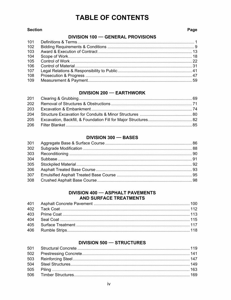
TABLE OF CONTENTS
Section Page
iv
DIVISION 100 __ GENERAL PROVISIONS 101 Definitions & Terms..................................................................................................... 1 102 Bidding Requirements & Conditions ........................................................................... 9 103 Award & Execution of Contract ................................................................................. 13 104 Scope of Work........................................................................................................... 18 105 Control of Work ......................................................................................................... 22 106 Control of Material ..................................................................................................... 31 107 Legal Relations & Responsibility to Public ................................................................ 41 108 Prosecution & Progress ............................................................................................ 47 109 Measurement & Payment.......................................................................................... 59
DIVISION 200 __ EARTHWORK 201 Clearing & Grubbing.................................................................................................. 69 202 Removal of Structures & Obstructions ...................................................................... 71 203 Excavation & Embankment ....................................................................................... 74 204 Structure Excavation for Conduits & Minor Structures ............................................. 80 205 Excavation, Backfill, & Foundation Fill for Major Structures...................................... 82 206 Filter Blanket ............................................................................................................. 85
DIVISION 300 __ BASES 301 Aggregate Base & Surface Course ........................................................................... 86 302 Subgrade Modification .............................................................................................. 88 303 Reconditioning .......................................................................................................... 90 304 Subbase .................................................................................................................... 91 305 Stockpiled Material .................................................................................................... 92 306 Asphalt Treated Base Course ................................................................................... 93 307 Emulsified Asphalt Treated Base Course ................................................................. 95 308 Crushed Asphalt Base Course.................................................................................. 98
DIVISION 400 __ ASPHALT PAVEMENTS AND SURFACE TREATMENTS
401 Asphalt Concrete Pavement ................................................................................... 100 402 Tack Coat................................................................................................................ 112 403 Prime Coat .............................................................................................................. 113 404 Seal Coat ................................................................................................................ 115 405 Surface Treatment .................................................................................................. 117 406 Rumble Strips.......................................................................................................... 118
DIVISION 500 __ STRUCTURES 501 Structural Concrete ................................................................................................. 119 502 Prestressing Concrete............................................................................................. 141 503 Reinforcing Steel..................................................................................................... 147 504 Steel Structures....................................................................................................... 149 505 Piling ....................................................................................................................... 163 506 Timber Structures.................................................................................................... 169

TABLE OF CONTENTS - Continued Section Page
v
507 Bridge Railing.......................................................................................................... 172 508 Waterproofing Membrane ....................................................................................... 173 509 Microsilica Modified Concrete Overlay.................................................................... 175 510 Removal of Concrete Bridge Deck.......................................................................... 182 511 Mechanically Stabilized Earth Wall ......................................................................... 185 512 Forms and Falsework.............................................................................................. 188 513 Field Painting of Steel Structures............................................................................ 197
DIVISION 600 __ MISCELLANEOUS CONSTRUCTION 601 Metal Flume Downdrains ........................................................................................ 205 602 Structural Plate Pipe ............................................................................................... 206 603 Culverts & Storm Drains.......................................................................................... 207 604 Manholes & Inlets.................................................................................................... 210 605 Underdrains............................................................................................................. 212 606 Guardrail ................................................................................................................. 214 607 Fences .................................................................................................................... 218 608 Sidewalks ................................................................................................................ 220 609 Curbing.................................................................................................................... 222 610 Ditch Lining ............................................................................................................. 225 611 Riprap...................................................................................................................... 226 612 Sacked Concrete Slope Protection ......................................................................... 227 613 Monuments & Markers ............................................................................................ 229 614 Concrete Barrier...................................................................................................... 230 615 Standard Signs........................................................................................................ 231 616 Thaw Pipe & Thaw Wires........................................................................................ 235 617 Railroad Crossings.................................................................................................. 241 618 Seeding ................................................................................................................... 244 619 Soil Stabilization...................................................................................................... 246 620 Topsoil..................................................................................................................... 247 621 Planting Trees and Shrubs...................................................................................... 248 622 Rest Area Facilities ................................................................................................. 253 623 Block Sodding ......................................................................................................... 258 624 Calcium Chloride for Dust Control........................................................................... 259 625 Pipe Hand Rail ........................................................................................................ 260 626 Sanitary Sewer System........................................................................................... 261 627 Water System.......................................................................................................... 263 630 Geotextile for Embankment Separation & Stabilization........................................... 268 631 Geotextile for Subsurface Drainage & Erosion Control ........................................... 270 632 Paving Fabric .......................................................................................................... 272 633 Silt Fence ................................................................................................................ 273 634 Geogrid Soil Reinforcement .................................................................................... 274 635 Insulation Board ...................................................................................................... 276 636 Gabions................................................................................................................... 277 639 Driveways................................................................................................................ 278

TABLE OF CONTENTS- Continued
Section Page
vi
640 Mobilization & Demobilization ................................................................................. 279 641 Erosion, Sediment, & Pollution Control ................................................................... 280 642 Construction Surveying & Monuments.................................................................... 285 643 Traffic Maintenance................................................................................................. 291 644 Services to be Furnished by the Contractor............................................................ 305 646 CPM Scheduling ..................................................................................................... 309 660 Signals & Lighting ................................................................................................... 311 661 Electrical Load Centers ........................................................................................... 332 670 Traffic Markings....................................................................................................... 336
DIVISION 700 __ MATERIALS 701 Hydraulic Cement.................................................................................................... 340 702 Asphalt Materials..................................................................................................... 341 703 Aggregates.............................................................................................................. 343 704 Masonry Units ......................................................................................................... 347 705 Joint Materials ......................................................................................................... 348 706 Concrete & Plastic Pipe .......................................................................................... 349 707 Metal Pipe ............................................................................................................... 350 708 Paints ...................................................................................................................... 351 709 Reinforcing Steel & Wire Rope ............................................................................... 352 710 Fence and Guardrail ............................................................................................... 353 711 Concrete Curing Materials & Admixtures ................................................................ 354 712 Miscellaneous ......................................................................................................... 355 713 Structural Timber, Lumber & Piling ......................................................................... 362 714 Preservatives for Timber ........................................................................................ 362 715 Steel for Piles .......................................................................................................... 363 716 Structural Steel........................................................................................................ 364 718 Steel Forgings ......................................................................................................... 366 719 Steel, Gray-Iron & Malleable-Iron Castings............................................................. 366 720 Elastomeric Pads .................................................................................................... 367 721 Prestressing Steel & Fittings ................................................................................... 368 722 Bridge Railing.......................................................................................................... 369 723 Water Stops ............................................................................................................ 369 724 Seed........................................................................................................................ 370 725 Fertilizer .................................................................................................................. 370 726 Topsoil..................................................................................................................... 371 727 Soil Stabilization Material ........................................................................................ 372 729 Geosynthetics ......................................................................................................... 374 730 Sign Materials ......................................................................................................... 375 740 Signals and Lighting Materials ................................................................................ 378 THE INDEX ......................................................................................................................... 405 CONVERSION TABLES, U.S. CUSTOMARY / METRIC .................................................. 431

1 ALASKA 2004
DIVISION 100 -- GENERAL PROVISIONS
SECTION 101
DEFINITIONS AND TERMS
101-1.01 GENERAL. The following terms and definitions apply in these Specifications. If a term is not defined, the ordinary, technical, or trade meanings for that term shall apply, within the context in which it is used. Titles and headings of sections, subsections, and subparts are intended for convenience of reference and will not govern their interpretation. Cited publications refer to the most recent issue, including interim publications, in effect on the date of the Invitation To Bid, unless specified by year or date. These Specifications are written to the Bidder or Contractor. Unless otherwise noted, all actions required by the specifications are to be performed by the Bidder, the Contractor, or the Contractor's agent. Beginning in Division 200 we use imperative mood and active voice to communicate the Contractor's responsibilities in a direct and concise manner. Omission of words or phrases such as “a,” “an,” “the,” “the Contractor shall,” “unless otherwise specified,” or “unless otherwise directed” is intentional. Interpret the Contract as if they were included. Beginning in Division 200 whenever anything is, or is to be, done, if, as, or, when, or where “acceptable, accepted, approval, approved, authorized, determined, designated, directed, disapproved, ordered, permitted, rejected, required, satisfactory, specified, submit, sufficient, suitable, suspended, unacceptable, unsatisfactory, or unsuitable,” the expression is to be interpreted as if it were followed by the words “by the Engineer” or “to the Engineer.” 101-1.02 ACRONYMS. Acronyms used in the Contract include the following (publications and plans are italicized): AAC Alaska Administrative Code AASHTO American Association of State Highway and Transportation Officials ACI American Concrete Institute AITC American Institute of Timber Construction ANSI American National Standards Institute AKOSH Alaska Occupational Safety and Health AS Alaska Statute ASDS Alaska Sign Design Specifications ASME American Society of Mechanical Engineers ASTM American Society for Testing & Materials ATM Alaska Test Method (see Alaska Test Methods Manual) ATSSA American Traffic Safety Services Association AWPA American Wood Preservers Association AWG American Wire Gage AWS American Welding Society AWWA American Water Works Association CFR Code of Federal Regulations CRSI Concrete Reinforcing Steel Institute DOLWD Alaska Department of Labor and Workforce Development

SECTION 101
2 ALASKA 2004
DOT&PF Alaska Department of Transportation and Public Facilities EEI Edison Electrical Institute EIA Electronic Industries Association FHWA Federal Highway Administration FOP Field Operating Procedure (see Alaska Test Methods Manual) FSS Federal Specifications and Standards, General Services Administration IMSA International Municipal Signal Association ICEA Insulated Cable Engineers Association ITE Institute of Transportation Engineers MRP Mining and Reclamation Plan MUTCD Manual on Uniform Traffic Control Devices NEC National Electrical Code NESC National Electrical Safety Code NEMA National Electrical Manufacturers Association SAE Society of Automotive Engineers SSHC DOT&PF Standard Specifications for Highway Construction SSPC Steel Structures Painting Council SWPPP Storm Water Pollution Prevention Plan UL Underwriters Laboratory WAQTC Western Alliance for Quality in Transportation Construction (see ATM Manual) 101-1.03 DEFINITIONS. ADDENDA. Clarifications, corrections, or changes to the Plans, Specifications, or other Contract documents issued graphically or in writing by the Department after the advertisement but prior to bid opening. ADVERTISEMENT. The public announcement, as required by law, inviting bids for specified work or materials. AGREED PRICE. An amount negotiated between the Department and the Contractor after Contract award for additional work performed or additional materials supplied under the Contract. ALASKA TEST METHODS MANUAL. The materials testing manual used by the Department. Contains Alaska Test Methods, WAQTC Test Methods, WAQTC FOPs for AASHTO Test Methods, and Alaska Standard Practices for evaluating test results and calibrating testing equipment. AWARD. Acceptance of the successful bid by the Department. The award is effective upon execution of the Contract by the Contracting Officer. BASE COURSE. One or more layers of specified material placed on a subbase or subgrade to support a surface course. BID. The bidder’s offer, on the prescribed forms, to perform the specified work at the prices quoted. BID BOND. A type of bid guaranty. BIDDER. An individual, firm, corporation, joint venture, or any acceptable combination of individuals and entities submitting a bid for the advertised work. BID GUARANTY. The security furnished with a bid to guarantee that the bidder will enter into a contract if the Department accepts the bid.
SECTION 101
3 ALASKA 2004
BRIDGE. A structure, including supports, erected over a depression or an obstruction, such as water, highway, or railway; and having a track or passageway for carrying traffic or other moving loads and a length measured along the roadway center of more than 20 feet between undercopings of abutments or spring lines of arches or extreme ends of openings of multiple boxes. The length of a bridge structure is the overall length measured along the line of survey stationing between backs of abutment backwalls or between ends of the bridge floor. CALENDAR DAY. Every day shown on the calendar, beginning and ending at midnight. CHANGE ORDER. A written order by the Department to the Contractor making changes to the Contract, within its general scope, and establishing the basis of payment and time adjustment, if any, for the work affected. COMPLETION DATE. The date on which all Contract work is specified to be completed. CONSTRUCTION. Physical activity by the Contractor or any Subcontractor using labor, materials or equipment within the Project, or within material sources planned for use on the Project. CONTINGENT SUM. A method for paying for a Contract bid item reserved by the Department for specified contingencies. The Contractor shall perform Contingent Sum work only upon the Directive of the Engineer. The basis of payment for Contingent Sum work shall be specified in the Contract or the Directive. CONTRACT. The written agreement between the Department and the Contractor setting forth the obligations of the parties for the performance and completion of the work. The Contract includes the Invitation To Bid, Bid Form, Standard Specifications, Standard Modifications, Special Provisions, Plans, Bid Schedule, Contract Forms, Contract Bonds, Addenda, and any Change Orders, Interim Work Authorizations, Directives, or Supplemental Agreements that are required to complete the work in an acceptable manner, all of which constitute one instrument. CONTRACTING OFFICER (PROCUREMENT OFFICER). The person authorized by the Commissioner of the Department to enter into and administer the Contract on behalf of the Department. The Contracting Officer has authority to make findings, determinations, and decisions with respect to the Contract and, when necessary, to modify or terminate the Contract. The Contracting Officer is identified on the Invitation To Bid. CONTRACT ITEM (PAY ITEM). A specifically described item of Contract work listed on the Bid Schedule or in a Change Order. CONTRACTOR. The individual, firm, corporation, joint venture, or any acceptable combination of individuals and entities contracting with the Department for performance of the Contract. CONTRACT TIME. The time allowed under the Contract, including authorized time extensions, for the completion of all work by the Contractor. Contract time may be specified either in calendar days or by completion date. CONTROLLING ITEM. Any feature of the work considered at the time by the Engineer: (1) essential to the orderly completion of the work and (2) a feature which, if delayed, will delay the time of completion of the Contract (such as an item of work on the critical path of a network schedule). COST. Amounts actually incurred by the Contractor in the performance of the Contract that are (a) actually reflected in contemporaneously maintained accounting or other financial records and (b) supported by original source documentation. Costs are to be stated in U.S. dollars.

SECTION 101
4 ALASKA 2004
CULVERT. Any structure not classified as a bridge that provides an opening under the embankment. DAY. Calendar day unless preceded by the word “working”. DEPARTMENT. The State of Alaska Department of Transportation and Public Facilities. DIRECTIVE. A written communication to the Contractor from the Engineer enforcing or interpreting a Contract requirement or ordering commencement or suspension of an item of work already established in the Contract. ENGINEER. The authorized representative of the Department's Contracting Officer. The Engineer is responsible for administration of the Contract. EQUIPMENT. All machinery, tools, apparatus, and supplies necessary to preserve, maintain, construct, and complete the work. EQUITABLE ADJUSTMENT. An increase or decrease in Contract price or time calculated according to the terms of this Contract. EXTRA WORK. An item of work not provided for in the Contract as awarded but found essential by the Engineer for the satisfactory completion of the Contract within its intended scope. HIGHWAY, STREET, OR ROAD. A general term denoting a public way used by vehicles and pedestrians, including the entire area within the right-of-way. HOLIDAYS. State of Alaska legal holidays are: 1. New Year's Day - January 1 2. Martin Luther King, Jr. Day - Third Monday in January 3. Presidents' Day - Third Monday in February 4. Seward's Day - Last Monday in March 5. Memorial Day - Last Monday in May 6. Independence Day - July 4 7. Labor Day - First Monday in September 8. Alaska Day - October 18 9. Veteran's Day - November 11 10. Thanksgiving Day - Fourth Thursday in November 11. Christmas Day - December 25 12. Every Sunday 13. Every day designated by public proclamation by the President of the United States or the
governor as a legal holiday. If a holiday listed above falls on a Saturday, Saturday and the preceding Friday are both legal holidays for officers and employees of the state. If the holiday falls on a Sunday, except (12) above, Sunday and the following Monday are both legal holidays (See AS 44.12). INSPECTOR. The Engineer's representative authorized to make detailed inspections of Contract performance and materials. INTERIM WORK AUTHORIZATION. A written order by the Engineer initiating changes to the Contract, within its general scope, until a subsequent Change Order is executed. INVITATION TO BID. The advertisement for bids for all work or materials on which bids are required.

SECTION 101
5 ALASKA 2004
MAJOR CONTRACT ITEM. A Contract item with a total value of 5 percent or more of the Contract award amount. MATERIALLY UNBALANCED BID. A mathematically unbalanced bid that either (a) gives rise to a reasonable doubt that it will ultimately result in the lowest overall cost to the Department, even though it may be the lowest bid or (b) is so unbalanced as to be tantamount to allowing a significant advance payment. MATERIALS. Substances specified for use in the construction of the project. MATERIALS CERTIFICATION LIST (MCL). A list of materials for which certifications must be submitted to the Engineer. The MCL will also designate electrical products requiring listing by an approved independent electrical testing laboratory. The MCL is included in the Contract documents as an appendix. MATHEMATICALLY UNBALANCED BID. A bid (a) where each pay item fails to carry its share of the cost of the work plus the bidder’s overhead and profit, or (b) based on nominal prices for some pay items and enhanced prices for other pay items. MEDIAN. The portion of a divided highway separating the traveled ways. MINOR CONTRACT ITEM. A Contract item with a total value of less than 5 percent of the Contract award amount. NOTICE OF INTENT TO AWARD. The written notice by the Department announcing the apparent successful bidder and establishing the Department's intent to award the Contract when all required conditions are met. NOTICE TO PROCEED. Written notice to the Contractor to begin the Contract work. ORIGINAL GROUND (OG). The ground surface prior to the start of work. PATHWAY. A paved path for multiple uses. PAVEMENT STRUCTURE. The combination of subbase, base course, and surface course placed on a subgrade to support the traffic load and distribute the traffic load to the roadbed. PAYMENT BOND. The security furnished by the Contractor and the Contractor’s Surety to guarantee payment of all persons who supply labor and material in prosecution of the work provided for in the contract. PERFORMANCE BOND. The security furnished by the Contractor and the Contractor’s Surety to guarantee performance and completion of the work provided for in the contract. PLANS. Contract drawings, profiles, typical cross sections, Standard Drawings, working drawings, shop drawings and supplemental drawings or reproductions showing the location, character, dimensions, and details of the work. PRECONSTRUCTION CONFERENCE. A meeting between the Contractor and the Engineer to discuss the project before the Contractor begins the work. PROFILE. The vertical elevation of the surface of the layer at the location indicated. On a roadbed it is typically indicated at the longitudinal centerline of the top layer of pavement. On a material or fabrication it may be used to indicate a thickness of material or thickness of a coating.

SECTION 101
6 ALASKA 2004
PROJECT. (a) The specific section of the highway or other property and related facilities on which construction is to be performed, or (b) the work that is to be performed under the Contract whether completed or partially completed. RESOURCES. Labor, equipment, materials, supplies, tools, transportation, and supervision necessary to perform the work. RESPONSIBLE BIDDER. A bidder that the Department determines has the skill, ability, financial resources, legal capacity to contract, equipment, required licenses, integrity, satisfactory record of performance and that is otherwise fully capable of performing the Contract. RESPONSIVE BID. A bid that the Department determines conforms in all material respects with the solicitation for bids. RIGHT-OF-WAY. Land or property or an interest in property available for a project. The uses allowed in portions of right-of-way may be restricted. ROADBED. Graded portion of a highway within top and side slopes, prepared as a foundation for the pavement structure and shoulders. ROADSIDE. A general term denoting the area adjoining the outer edge of the roadway. Extensive areas between the roadways of a divided highway may also be considered roadside. ROADWAY. Portion of a highway including shoulders, for vehicular use. SHOULDER. Portion of the roadway adjacent to the traveled way for accommodation of stopped vehicles for emergency use, and for lateral support of base and surface courses. SIDEWALK. Portion of the project constructed for the exclusive use of pedestrians. SPECIAL PROVISION. Addition or revision that amends or supersedes the Standard Specifications or Standard Modifications, and is applicable to an individual project. SPECIALTY ITEM. A Contract item identified in the Contract that requires highly specialized knowledge, abilities, or equipment not ordinarily available in the type of contracting organizations qualified and expected to bid on the contract. SPECIFICATIONS. General term applied to all Contract terms, conditions, directions, provisions, and requirements. STANDARD DRAWING. Drawing approved by the Department for repetitive use, showing details to be used where appropriate. STANDARD MODIFICATION. Addition or revision that amends or supersedes the Standard Specification, and is approved by the Department for general application and repetitive use. STANDARD SPECIFICATIONS. A book or electronic file of specifications approved by the Department for general application and repetitive use. STATE. The State of Alaska, acting through its authorized representative. STATION. A distance of 100 feet measured horizontally, usually along centerline. STRUCTURE. Bridge, culvert, catch basin, drop inlet, retaining wall, cribbing, manhole, endwall, building, sewer, service pipe, underdrain, foundation drain, or other similar feature that may be encountered in the work.

SECTION 101
7 ALASKA 2004
SUBBASE. Layer of specified material between the subgrade and base course. SUBCONTRACTOR. Individual or legal entity to whom or to which the Contractor sublets part of the Contract. SUBGRADE. The top surface of a roadbed on which the pavement structure and shoulders are constructed. SUBSIDIARY. Work or material not measured or paid for directly. Compensation for such work is included in the payment for other items of work. SUBSTANTIAL COMPLETION. The point at which the project (1) can be safely and effectively used by the public without further delays, disruption, or other impediments; and (2) pavement structure, shoulder, drainage, sidewalk, permanent signing and markings, guardrail and other traffic barrier, safety appurtenance, utilities, lighting and all bridge deck and parapet work is complete. For projects that will not be opened to the traveling public or are being built in phases, the work is substantially complete when it is ready for the subsequent project. SUBSTRUCTURE. All portions of a bridge below the bearings of simple and continuous spans, skewbacks of arches and tops of footings of rigid frames, including backwalls, wingwalls, and wing protection railings. SUPERINTENDENT. The Contractor's authorized representative in responsible charge of the work. SUPERSTRUCTURE. The entire bridge structure above the substructure. SUPPLEMENTAL AGREEMENT. Negotiated written agreement between the Department and the Contractor authorizing performance of work beyond the general scope of, but in conjunction with, the original Contract. Supplemental agreements are new procurements under the State Procurement Code, AS 36.30. SURETY. Corporation, partnership, or individual, other than the Contractor, executing a bond furnished by the Contractor. SURFACE COURSE. Top homogenous layer of the pavement structure. It is designed to withstand the wear of traffic and the disintegrating effects of climate. Sometimes called the wearing course. TRAFFIC CONTROL PLAN (TCP). One or more project-specific plans detailing the routing of vehicular or pedestrian traffic through or around a construction area including the location of all traffic control devices. TRAIL. An unpaved path for multiple uses. TRAVELED WAY. Portion of the roadway designed for vehicle use, excluding shoulders. UTILITY. Line, facility, or system for producing, transmitting, or distributing communications, power, electricity, light, heat, gas, oil, crude products, water, steam, waste, storm water not connected with highway drainage, or other similar commodity, including a publicly owned fire or police signal system, street lighting system, or railroad which directly or indirectly serves the public. Also means a utility company, inclusive of any subsidiary.

SECTION 101
8 ALASKA 2004
WORK. Depending on the context, (a) The act of furnishing all resources for the project and performing all duties and obligations required by the Contract or (b) the physical construction, facility or end–product that is contemplated under the Contract, whether completed or partially completed. WORKING DAYS. Calendar days, except Saturdays and state holidays. WORKING DRAWINGS. Stress sheets, shop drawings, erection plans, falsework plans, framework plans, cofferdam plans, bending diagrams for reinforcing steel, wiring diagrams and schematics, traffic control plans, night work lighting plans, or any other supplementary plans or similar data which the Contractor is required to submit to the Engineer for approval.

9 ALASKA 2004
SECTION 102
BIDDING REQUIREMENTS AND CONDITIONS 102-1.01 QUALIFICATION OF BIDDERS. A bidder shall: 1. On wholly state-funded projects, submit evidence of Contractor Registration, under AS 08.18,
and valid Alaska Business License at the time designated for bid opening; 2. On federal-aid projects, submit evidence of Alaska Business License and Contractor
Registration prior to award; and 3. When requested, submit a completed Contractor’s Questionnaire (Form 25D-8) stating
previous experience in performing comparable work, business and technical organization, financial resources, and equipment available to be used in performing the work.
All firms desiring to participate in DOT&PF construction projects must register annually by submitting a completed Bidder Registration (Form 25D-6). 102-1.02 CONTENTS OF BID PACKAGE. Upon request, the Department will furnish prospective bidders with a bid package, at the price stated in the Invitation To Bid. The bid package includes the following: 1. Location and description of the project; 2. Estimates of quantities of work and materials to be furnished; 3. Schedule of contract items for which bid prices are invited; 4. Time in which the work must be completed; 5. Amount of the bid guaranty; 6. Date, time, and place for the bid opening; 7. Plans and specifications; and 8. Bid forms. Unless otherwise stated in the bid package, the Plans, Standard Specifications, Standard Modifications, Special Provisions, permits, forms and any other documents designated in the bid package are considered a part of the bid whether attached or not. 102-1.03 INTERPRETATION OF QUANTITIES IN BID SCHEDULE. Bid prices shall be based on the estimated quantities shown in the bid schedule. Quantities of work to be done and materials to be furnished are approximate and are prepared only for the comparison of bids. These quantities may increase, decrease, or be eliminated as provided. Payment for unit price items will be made for the actual accepted quantities of work performed and materials furnished under the Contract, as determined using the method of measurement specified in the Contract. 102-1.04 EXAMINATION OF PLANS, SPECIFICATIONS, SPECIAL PROVISIONS, AND WORK SITE. Bidders shall examine the work site and all Contract documents before preparing a bid. Submitting a bid is a binding representation that the bidder has examined the work site, is aware of the conditions to be encountered, and has examined and understands all of the Contract documents, including plans and specifications. Bidders shall examine the bidding requirements listed under Subsection 105-1.06 Utilities. Material Reports, Soils Investigation Reports, and other records are made available for information purposes only. It is made available so bidders may have access to the same information available to the Department. It is not intended as a substitute for independent investigation, interpretation, or judgment of the bidder. The Department is not responsible for any interpretation or conclusion drawn from its records by the bidder. Bidders shall examine Subsection 106-1.02 Material Sources for further information.

SECTION 102
10 ALASKA 2004
Any questions about bidding procedures, site conditions, or Contract requirements must be submitted in writing to the persons designated on the Invitation To Bid. Questions must be submitted in sufficient time to get a reply before submitting a bid. No oral responses or other oral statements are binding on the Department. Any response to a material question shall be issued by addendum sent to all bidders. 102-1.05 PREPARATION OF BID. Bids shall only be submitted on the forms furnished by the Department or legible copies of the Department's forms. All entries shall be legible and in ink or type. Bidders shall: 1. Enter all prices required on the Bid Schedule, in figures; 2. Enter a unit price for each contract item for which a quantity is given; 3. Enter the products of the respective unit prices and quantities in the column provided; 4. Enter lump sum prices for lump sum contract items in the column(s) provided; and 5. Enter the total amount of all contract items for the basic bid and, when specified, any
alternates. When a bid item contains a choice to be made by the bidder, the bidder shall indicate a choice according to the Specifications for that item. No further choice is permitted. The bid must be signed in ink by the person or persons authorized to sign the Contract for the bidder. If a bidder is a corporation, the bid must be signed by a corporate officer with authority to bind the corporation. If a bidder is a partnership, a partner must sign. If the bidder is a joint venture, each principal member must sign. If a bidder is a sole proprietorship, the owner must sign. Each person signing the bid must initial any changes made to entries on the bid forms. For multiple-project bid openings, bidders may limit the total dollar amount or number of projects to be accepted by completing the following statement and adding it to the Bid Form for at least one of the projects being bid. The Department will then determine which of the low bids it will accept, up to the total indicated.
“We wish to disqualify all of our successful bids at this bid opening which exceed the total of $_____________ or ____ contracts and hereby authorize the Department to determine which bids to disqualify, based on this limit.”
102-1.06 NONRESPONSIVE BIDS. 1. A bid shall be rejected as nonresponsive if it:
a. Is not properly signed by an authorized representative of the bidder in ink and in a legally binding manner;
b. Contains unauthorized additions, conditional or alternative bids, or other irregularities that make the bid incomplete, indefinite, or ambiguous;
c. Includes a reservation of the right to accept or reject any award, or to enter into a contract pursuant to an award, except for an award limitation under Subsection 102-1.05;
d. Fails to include an acceptable bid guaranty with the bid; e. Is materially unbalanced; or f. Fails to meet any other material requirement of the Invitation To Bid.
2. A bid may be rejected as nonresponsive, in the Department's discretion, if it:
a. Is not typed or completed in ink; b. Fails to include an acknowledgement of receipt of each addendum by assigned number
and date of issue; or c. Is missing a bid price for any pay item, except when alternate pay items are authorized.
102-1.07 BID GUARANTY. Bids shall be accompanied by a bid guaranty in the amount specified on the Invitation To Bid. The guaranty shall be unconditionally payable to the State of Alaska and shall be in the form of an acceptable Bid Bond (Form 25D-14), or a certified check, cashier's check, or money order.
SECTION 102
11 ALASKA 2004
The surety of a Bid Bond may be any corporation or partnership authorized to do business in Alaska as an insurer under AS 21.09. A legible power of attorney shall be included with each Bid Bond. An individual surety will not be accepted as a bid guaranty. 102-1.08 DELIVERY OF BIDS. Bids shall be submitted in the envelope furnished by the Department, or one of the same general size and shape that has the same identifying information. The envelope shall clearly indicate its contents and the designated address, as shown on the Invitation to Bid. Bids for other work may not be included in the envelope. Electronic or faxed bids will not be considered, unless specifically called for in the Invitation to Bid. 102-1.09 WITHDRAWAL OR REVISION OF BIDS. Bidders may withdraw or revise a bid in writing delivered by mail or by fax, provided that the designated office receives the withdrawal or revision before the time set for opening of bids. Revisions shall include both the modification of the unit bid price and the total modification of each item modified, but shall not reveal the amount of the total original or revised bids. 102-1.10 PROTEST OF INVITATION TO BID. An interested party, as defined in AS 36.30.699, may protest an Invitation to Bid before the bid opening in accordance with AS 36.30.560 and AS 36.30.565. Submit a protest to the Contracting Officer. 102-1.11 ADDENDA REQUIREMENTS. The Department will issue addenda if it determines, in its discretion, that clarifications or changes to the Contract documents or bid opening date are needed. The Department may send addenda by any reasonable method such as mail, courier, fax, or may post the addenda on its web site. Unless picked up in person or included with the bid documents, addenda or notice that an addenda has been issued will be addressed to the individual or company to whom bidding documents were issued and sent to the address or fax number on the plan holders’ list. Notwithstanding the Department’s efforts to distribute addenda, bidders are responsible for ensuring that they have received all addenda affecting the Invitation To Bid. Bidders must acknowledge all addenda received, either on the Bid Form or by fax prior to the scheduled time of bid opening. If a bidder received no addenda, the bidder shall enter “None” on the Bid Form. 102-1.12 RECEIPT AND OPENING OF BIDS. The Department will only consider bids, revisions, and withdrawals received before the scheduled time of bid opening. Bids will be opened and read publicly at the time and place indicated in the Invitation to Bid. The Department is not responsible for prematurely opening or failing to open bids that are improperly addressed or identified. 102-1.13 RESPONSIBILITY OF BIDDERS. The Department may find a bidder is nonresponsible for any one of the following reasons, but is not limited in its responsibility analysis to the following factors: 1. Evidence of bid rigging or collusion; 2. Fraud or dishonesty in the performance of previous contracts; 3. More than one bid for the same work from an individual, firm, or corporation under the same
or different name; 4. Unsatisfactory performance on previous or current contracts; 5. Failure to pay, or satisfactorily settle, all bills due for labor and material on previous contracts; 6. Uncompleted work that, in the judgment of the Department, might hinder or prevent the
bidder’s prompt completion of additional work, if awarded; 7. Failure to reimburse the state for monies owed on any previous contracts; 8. Default under previous contracts;
SECTION 102
12 ALASKA 2004
9. Failure to submit evidence of registration and licensing; 10. Failure to comply with any qualification requirements of the Department; 11. Engaging in any activity that constitutes a cause for debarment or suspension under the
State Procurement Code (AS 36.30) or submitting a bid during a period of debarment; 12. Failure to satisfy the responsibility standards set out in state regulations; 13. Lack of skill, ability, financial resources, or equipment required to perform the contract; or 14. Lack of legal capacity to contract. Nothing contained in this section deprives the Department of its discretion in determining the lowest responsible bidder.

13 ALASKA 2004
SECTION 103
AWARD AND EXECUTION OF CONTRACT 103-1.01 CONSIDERATION OF BIDS. After the bids are opened and read, the bids will be mathematically checked and compared on the basis of the sum of the products of the bid schedule quantities and the unit bid prices. The unit bid prices govern if there is an error in extending the unit bid prices, or in totaling the extensions, or if an extension is missing. The results of the bid comparisons will be made available to the public as soon as practicable. Until the Award, the Department may reject any or all bids, waive minor informalities or advertise for new bids without liability to any bidder if the Department, in its discretion, determines that to do so is in the best interests of the state. A bidder may request withdrawal of a bid after opening and before the Award only in accordance with AS 36.30.160(b) and State procurement regulations. Submit the request to the Contracting Officer. An interested party, as defined in AS 36.30.699, may protest a proposed Award of contract as per AS 36.30.560 and AS 36.30.565. Submit the protest to the Contracting Officer. 103-1.02 SUBCONTRACTOR LIST. The apparent low bidder shall submit a completed Subcontractor List, Form 25D-5, within five working days following receipt of written notification by the Department that it is the low bidder. An apparent low bidder who fails to submit a completed Subcontractor List form within the time allowed will be declared nonresponsible and may be required to forfeit the bid security. The Department will then consider the next lowest bidder for award of the Contract. If a bidder fails to list a subcontractor, or lists more than one subcontractor for the same portion of work, and the value of that work is in excess of one-half of one percent of the total bid amount, the bidder agrees to perform that portion of work without a subcontractor and represents that it is qualified to perform that work. A bidder who lists as a subcontractor another contractor who, in turn, sublets the majority of the work required under the Contract, violates this subsection. A bidder or Contractor may, without penalty, replace a listed subcontractor who: 1. Fails to comply with licensing and registration requirements of AS 08.18; 2. Fails to obtain a valid Alaska business license; 3. Files for bankruptcy or becomes insolvent; 4. Fails to execute a subcontract for performance of the work for which the subcontractor was
listed, and the bidder acted in good faith; 5. Fails to obtain bonding acceptable to the Department; 6. Fails to obtain insurance acceptable to the Department; 7. Fails to perform the subcontract work for which the subcontractor was listed; 8. Must be replaced to meet the bidder's required state or federal affirmative action
requirements; 9. Refuses to agree or abide with the bidder's labor agreement; or 10. Is determined by the Department to be not responsible. In addition to the circumstances described above, a Contractor may in writing request permission from the Department to add a new subcontractor or replace a listed subcontractor. The Department will approve the request if it determines in writing that allowing the addition or replacement is in the best interest of the State.

SECTION 103
14 ALASKA 2004
A bidder or Contractor shall submit a written request to add a new subcontractor or replace a listed subcontractor to the Contracting Officer a minimum of five working days before the date the new subcontractor is scheduled to begin work on the construction site. The request must state the basis for the request and include supporting documentation acceptable to the Contracting Officer. If a bidder violates this subsection, the Contracting Officer may: 1. Cancel the Contract after Award without any damages accruing to the Department; or 2. After notice and a hearing, assess a penalty on the bidder in an amount not exceeding 10
percent of the value of the subcontract at issue. 103-1.03 AWARD OF CONTRACT. The Department will award the Contract to the lowest responsible and responsive bidder unless it rejects all bids. The Department will notify all bidders in writing of its intent to award. The Department will notify the successful bidder in writing of its intent to award the Contract and request that certain required documents, including the Contract Form, bonds, and insurance be submitted within the time specified. The successful bidder's refusal to sign the Contract and provide the requested documents within the time specified may result in cancellation of the notice of intent to award and forfeiture of the bid security. If an award is made, it will be made as soon as practicable and usually within 40 days after bid opening. Award may be delayed due to bid irregularities or a bid protest, or if the award date is extended by mutual consent. Bids shall be valid for 120 days after bid opening, and may be extended by mutual consent. 103-1.04 RETURN OF BID GUARANTY. The Department will return bid guaranties, other than bid bonds: 1. To all except the two lowest responsive and responsible bidders, as soon as practicable after
the opening of bids; and 2. To the two lowest responsive and responsible bidders immediately after Contract award. 103-1.05 PERFORMANCE AND PAYMENT BONDS. The successful bidder shall furnish all required Performance and Payment Bonds on forms provided by the Department for the sums specified in the Contract. If no sum is specified, the successful bidder shall comply with AS 36.25.010. The Surety on each bond may be any corporation or partnership authorized to do business in the state as an insurer under AS 21.09 or two responsible individual sureties approved by the Contracting Officer. If individual sureties are used, two individual sureties must each provide the Department with security assets located in Alaska equal to the specified amount of each bond. The net worth and the total value of the security assets of each individual surety shall not be less than the penal amount of the bond. In addition, each individual Surety, upon the Department's request, shall execute an affidavit of individual surety on a form provided by the Department. Each individual surety affidavit contains a Certificate of Sufficiency that must be signed by an official of an institution having full knowledge of assets and responsibilities of the Surety. Any costs incurred by the Contractor and the individual Surety are subsidiary and shall be borne by the Contractor or the individual Surety. In no event will the Department be liable for these costs. Individual sureties shall provide security by one, or a combination, of the following methods: 1. Escrow Account, with a federally insured financial institution, in the name of the Department.
Acceptable securities include, but are not limited to, cash, treasury notes, bearer instruments having a specific value, or money market certificates.
SECTION 103
15 ALASKA 2004
2. First Deed of Trust, with the Department named as beneficiary, against the unencumbered value of real property or an agreement by a second party, including deeds of trust, mortgage, lien, or judgment interests to subrogate their interests to the Department in the real property offered by the individual Surety. A title insurance policy, with the Department as a named beneficiary, and a current (within three months) professional appraisal or assessed valuation is required to ascertain the true value of the property offered as collateral. Fire and casualty insurance, with the Department as a named insured, and in limits and coverages acceptable to the Contracting Officer, are required if buildings or other valuable improvements are involved. The appraiser must acknowledge in writing that the appraisal is prepared for the benefit of the Department and the Department has the right to rely on its contents. The deed of trust must be recorded in the recording office where the property is located.
These bonds and security assets, as applicable, shall remain in effect for 12 months after the date of final payment or, if longer, until all obligations and liens under this Contract are satisfied, including, but not limited to, obligations under Subsection 107-1.19. The Department may, in its discretion, notify the bonding company or Surety of any potential default or liability. The Contractor shall substitute, within five working days, another bond or surety acceptable to the Department if an individual Surety or the Surety on any bond furnished in connection with the Contract: 1. Becomes insolvent or is declared bankrupt; 2. Loses its right to do business in any state affecting the work; 3. Ceases to meet Contract requirements; 4. Fails to furnish reports of financial condition upon request; or 5. Otherwise becomes unacceptable to the Department. When approved by the Contracting Officer, the Contractor may replace: 1. An individual surety with a corporate surety; or 2. Posted collateral with substitute collateral. Failure to maintain the specified bonds or to provide substitute bonds when required under this section may be grounds for withholding contract payments until substitute bonding is obtained, and may, in the Department's discretion, be grounds for declaring the Contractor in default. 103-1.06 INSURANCE REQUIREMENTS. The Contractor shall provide evidence of insurance with an insurance carrier or carriers satisfactory to the Department covering injury to persons and property suffered by the State of Alaska or by a third party as a result of operations under this contract by the Contractor or by any subcontractor. The Contractor's insurance shall provide protection against injuries to all employees of the Contractor and the employees of any subcontractor engaged in work under this Contract. All insurance policies shall be issued by insurers that (i) are permitted to transact the business of insurance in the State of Alaska under AS 21 and (ii) have a financial rating acceptable to the Department. The Contractor shall notify the Engineer, in writing, at least 30 days before cancellation of any coverage or reduction in any limits of liability. Where specific limits and coverages are shown, it is understood that they shall be the minimum acceptable. The requirements of this subsection shall not limit the Contractor’s indemnity responsibility under Subsection 107-1.13. Additional insurance requirements specific to this contract are contained in the Special Provisions, when applicable.
SECTION 103
16 ALASKA 2004
The Contractor shall maintain the following policies of insurance with the specified minimum coverages and limits in force at all times during the performance of the Contract: 1. Workers' Compensation: as required by AS 23.30.045, for all employees of the Contractor
engaged in work under this Contract. The Contractor shall be responsible for Workers' Compensation Insurance for any subcontractor who performs work under this Contract. The coverage shall include: a. Waiver of subrogation against the state; b. Employer's Liability Protection at $500,000 each accident/each employee and $500,000
policy limit; c. “Other States” endorsement if the Contractor directly utilizes labor outside of the State of
Alaska; d. United States Longshore and Harbor Workers’ Act Endorsement, whenever the work
involves activity over or about navigable water; and e. Maritime Employer’s Liability (Jones Act) Endorsement with a minimum limit of
$1,000,000, whenever the work involves activity from or on a vessel on navigable water.
2. Commercial General Liability: on an occurrence policy form covering all operations with combined single limits not less than: a. $1,000,000 Each Occurrence; b. $1,000,000 Personal Injury; c. $2,000,000 General Aggregate; and d. $2,000,000 Products-Completed Operations Aggregate.
3. Automobile Liability: covering all vehicles used in Contract work, with combined single limits
not less than $1,000,000 each occurrence.
4. Umbrella Coverage: for Contract amounts over $5,000,000 not less than $5,000,000 umbrella or excess liability. Umbrella or excess policy shall include products liability completed operations coverage and may be subject to $5,000,000 aggregate limits. Further, the umbrella or excess policy shall contain a clause stating that it takes effect (drops down) in the event the primary limits are impaired or exhausted.
The State of Alaska shall be named as an additional insured on policies required by paragraphs 2 thru 4 above. All of the above insurance coverages shall be considered to be primary and non-contributory to any other insurance carried by the State of Alaska, whether through self-insurance or otherwise. In any contract or agreement with subcontractors performing work, the Contractor shall require that all indemnities and waivers of subrogation it obtains, and any stipulation to be named as an additional insured it obtains, shall also be extended to waive rights of subrogation against the State of Alaska and to add the State of Alaska as an additional named indemnitee and as an additional insured. The apparent low bidder shall furnish evidence of insurance to the Department before award of the Contract. The evidence shall be issued to the Department and shall be either a certificate of insurance or the policy declaration page with all required endorsements attached and must: 1. Denote the type, amount, and class of operations covered; 2. Show the effective (and retroactive) dates of the policy; 3. Show the expiration date of the policy; 4. Include all required endorsements; 5. Be executed by the carrier's representative; and 6. If a certificate of insurance, include the following statement:
SECTION 103
17 ALASKA 2004
“This is to certify that the policies described herein comply with all aspects of the insurance requirements of (Project Name and Number). The insurance carrier agrees that it shall notify the Engineer, in writing, at least 30 days before cancellation of any coverage or reduction in any limits of liability.”
The Department’s acceptance of deficient evidence of insurance does not constitute a waiver of Contract requirements. Failure to maintain the specified insurance or to provide substitute insurance if an insurance carrier becomes insolvent, is placed in receivership, declares bankruptcy, or cancels a policy may be grounds for withholding Contract payments until substitute insurance is obtained, and may, in the Department's discretion, be sufficient grounds for declaring the Contractor in default. 103-1.07 EXECUTION AND APPROVAL OF CONTRACT. The successful bidder shall execute and return the Contract Form and all other required documents to the Department within the time specified, or within 15 days after receipt by the bidder if no time is specified. A contract is awarded only after it has been signed by the Contracting Officer. 103-1.08 FAILURE TO EXECUTE CONTRACT. If the successful bidder fails to appropriately execute and return the Contract Form and other documents within time specified, as required above, the Department may cancel the intent to award and keep the bid guaranty. The Department will then, in its discretion, award the Contract to the next lowest responsive and responsible bidder or readvertise the work. 103-1.09 ORAL STATEMENTS. The written terms of the Contract are binding. No oral statement of any person shall, in any manner or degree, modify or otherwise affect, change, or amend the terms of the Contract. 103-1.10 INTEGRATED CONTRACT. This Contract is an integrated document and contains the complete agreement and understanding of the parties. There are no unwritten agreements or understandings between the parties. Changes ordered or agreed upon, Directives given, or Equitable Adjustments issued under this Contract, and all other matters affecting the Contract, must be in writing in order to be binding and effective.

18 ALASKA 2004
SECTION 104
SCOPE OF WORK 104-1.01 INTENT OF CONTRACT. The intent of the Contract is to provide for the construction and completion of every detail of the described work. The Contractor shall furnish all labor, material, supervision, equipment, tools, transportation, supplies, and other resources required to complete the work in the time specified and in accordance with the Contract. 104-1.02 CHANGES. 1. Within Contract Scope. The Engineer may order changes within the general scope of the
Contract at any time, and without notice to sureties, including altering, ordering additions to, or ordering deletions of quantities of any item or portion of the work. These changes shall be made by a written Change Order and shall not invalidate the Contract or release the sureties. a. If the change does not materially differ in character or unit cost from specified Contract
work, the Contractor shall perform the work at the original contract measurement methods and prices, subject to the provisions of Subsection 109-1.04.
b. If the change is materially different in character or unit cost from that specified in the
Contract, a new Contract Item will be established, and an equitable adjustment to Contract price and Contract time shall be calculated by one of the following methods: (1) The Engineer and Contractor agree upon an adjustment to Contract price and
Contract time, and the Engineer issues a change order for the described work; (2) The Engineer requires the Contractor to proceed with the described work, with an
adjustment to contract price and contract time, calculated by time and materials basis under Subsection 109-1.05, and the Engineer issues a change order for the work. The Contractor shall keep complete daily records of the cost of such work; or
(3) The Engineer may issue a unilateral Change Order requiring the Contractor to proceed with the work with an adjustment to the payment amount or Contract time based on the Engineer's estimate of reasonable value. The Contractor shall keep complete daily records of the cost of such work.
c. If the Engineer eliminates a Contract item, the Contractor shall accept compensation
under Subsection 109-1.09. 2. Outside Contract Scope. Changes determined to be outside the general scope of the
Contract shall be made only by Supplemental Agreement issued in accordance with AS 36.30 and the State’s procurement regulations. Additional bonding or insurance may be required.
3. Cost and Pricing Data. Before a Change Order or Supplemental Agreement covering work for
which there is no established Contract price will be approved, the Contractor shall submit detailed cost or pricing data regarding the changed work. The cost or pricing data shall include an itemization of production rates and all costs including labor, materials, and equipment required for the work. The Contractor shall certify that the data submitted are, to the best of its knowledge and belief, accurate, complete, and current as of a mutually agreed date and that the data will continue to be accurate and complete during the performance of the changed work.
104-1.03 DIFFERING SITE CONDITIONS. The Contractor shall immediately notify the Engineer in writing and specifically describe the alleged differing site condition if the Contractor discovers: 1. Subsurface or latent physical conditions at the site, differing materially from those shown in
the Contract documents, that could not have been discovered by a careful examination of the site; or

SECTION 104
19 ALASKA 2004
2. Unknown physical conditions at the site, of an unusual nature, differing materially from those ordinarily encountered and generally recognized as inherent in work of the character provided for in the Contract.
Failure to give the Engineer immediate written notice of the alleged differing site condition as required under this section constitutes a waiver of any future claim arising from or relating to the alleged differing site condition. Unless otherwise directed by the Engineer, the Contractor shall leave the affected area undisturbed and suspend work in that area until the Engineer investigates the conditions. If the Engineer finds that such conditions differ materially and increase or decrease the cost of, or the time required for, performance of the Contract, the Engineer will prepare a Change Order for an Equitable Adjustment to the Contract. The Contractor shall cooperate with the Engineer’s preparation of the Change Order. If the Contractor and the Engineer are unable to reach an agreement concerning the alleged differing site condition, the Contractor may file a claim under Subsection 105-1.17. The Contractor shall keep accurate and detailed records of the actual cost of the work done as a result of the alleged differing site condition and shall allow the Engineer access to those records. Failure to keep records, to provide the Engineer with access to those records, or to give the notice required above will bar any recovery for the alleged differing site condition. 104-1.04 USE OF MATERIALS FOUND ON THE WORK. Before using borrow, the Contractor shall utilize Useable Excavation to construct the selected material layers on the project. For the purposes of this subsection, Useable Excavation is material encountered in the excavation that meets the requirements of Subsection 703-2.07 Selected Material. For excavating the Useable Excavation and constructing the selected material layers with Useable Excavation, the Contractor shall be paid only the unit bid price for excavation. Hauling, placing, compacting and other activities required to construct the selected material layers with Useable Excavation shall be subsidiary to excavation, and the Contractor shall not be paid additional sums for those activities. The Engineer may approve the use of borrow when Useable Excavation is not available. The Engineer may authorize the Contractor to use the Useable Excavation for Contract items other than construction of the selected material layers on the project, and the Contractor shall be paid both for the excavation of the Useable Excavation and for the other Contract item for which it is acceptably used. If this action results in a shortage of material for the selected material layers: 1. The Contractor shall replace Useable Excavation used for other Contract items on a yard for
yard basis with borrow acceptable to the Engineer; and 2. This replacement shall be at the Contractor's expense and at no additional cost to the
Department. The Contractor shall pay any royalties required for the borrow.
The Contractor shall not excavate or remove any material that is within the right-of-way but outside the slope and grade lines described in the Contract, without written authorization from the Engineer. In the event the Contractor has processed material from state-furnished sources in excess of the quantities required for performance of the Contract, the Department may retain possession of the surplus processed materials, including any waste material produced as a by-product, without obligation to pay the Contractor for processing costs. When the surplus materials are in a stockpile, the Engineer may direct the Contractor to leave the materials in the stockpile, level the stockpile(s) or remove the materials and restore the premises to a satisfactory condition at no additional cost to the Department. This provision does not apply to material specifically produced under Section 305, Stockpiled Material.

SECTION 104
20 ALASKA 2004
The Contractor may temporarily use material from a structure that is designated to be removed to erect a new structure, but shall not cut or otherwise damage such material without the Engineer's approval. 104-1.05 CLEANUP. The Contractor shall remove all rubbish, temporary structures, excess materials, and equipment from the project site, from state owned materials sources, and from all work areas before project completion.
104-1.06 VALUE ENGINEERING PROPOSALS BY CONTRACTOR. 1. Purpose and Scope. The purpose of this section is to encourage the Contractor to propose
changes to Contract designs, materials, or methods based on the Contractor's experience and ingenuity. The Value Engineering Proposals (VEPs) contemplated are those that may result in immediate savings to the Department under this Contract without impairing essential functions and characteristics of the Project, including, but not limited to: service life, economy of operation, ease of maintenance, desired appearance, and safety. Cost savings on this project resulting from VEPs offered by the Contractor and accepted by the Department shall be shared equally between the Contractor and the Department.
2. Submitting Proposals. All VEPs must be in writing. The Contractor shall submit the following with each VEP: a. A statement that the proposal is submitted as a Value Engineering Proposal under
Subsection 104-1.06; b. A description of the difference between the existing Contract requirements and the proposed
change, stating the comparative advantages and disadvantages of each, including effects on service life, economy of operations, ease of maintenance, desired appearance, and safety;
c. Drawings or specifications that show the proposed revisions relative to the original Contract requirements. The Contractor may submit schematics for conceptual approval of the proposal;
d. A detailed and complete cost estimate comparing the original estimated costs for performing the work under the existing Contract and under the proposed VEP;
e. A summary of the Contractor's development costs for the VEP, including costs for designing, testing, preparing and submitting the VEP;
f. A description and estimate of added costs the Department may incur in implementing the VEP, such as review, testing and evaluation of the VEP and Contract administration costs;
g. A date by which the Department must make a decision to obtain the cost savings projected in the VEP. The date identified must allow a reasonable time for the Department to conduct an adequate review and evaluation of the VEP and process a Change Order without affecting the Contractor’s schedule;
h. A statement of the probable effect the VEP would have on the Contract completion time. The Department's approval of the VEP shall not change the Contract completion date unless a change to the completion date is specifically provided for in the Change Order authorizing the VEP; and
i. A description of any previous use or testing of the proposed change and the conditions and results. If the proposal was previously submitted on another Department project, indicate the date, project name and number, and the action taken by the Department.
3. Conditions. VEPs will be considered only when all of the following conditions are met:
a. The Contractor has not based any bid prices on the anticipated acceptance of a VEP. If the VEP is rejected, the Contractor shall complete the work at the Contract prices.
b. VEPs, regardless of their approval status, become the property of the Department. The Contractor shall submit VEPs without use or disclosure restrictions. The Department shall have the right to use, duplicate or disclose the VEP and any data necessary to use the VEP on the Project, on any other project, and on any other Contracts. The Contractor shall identify any trade secret information, patented materials or proprietary processes that restrict use of the VEP.

SECTION 104
21 ALASKA 2004
c. The Department is the sole judge as to whether a VEP qualifies for consideration and evaluation. It may reject any VEP that does not allow a reasonable time for adequate review and evaluation by the Department or that requires excessive time or costs for review, evaluations, or investigations, or which is not consistent with the Department's design standards and policies, safety considerations, land use restrictions, permit stipulations, right-of way limitations, or other essential criteria for the project. The Department may reject a VEP without obligation to the Contractor if it contains proposals that are already under consideration by the Department or that have already been authorized for the Contract.
d. If additional information is needed to evaluate a VEP, the Contractor shall provide it in a timely manner. Failure to do so may result in rejection of the VEP.
e. The Contractor may submit VEPs for an approved subcontractor if the Department makes reimbursement to the Contractor.
f. If the Contractor hires a design professional to prepare the proposal, that professional must seal the documents and provide evidence of Professional Liability Insurance with limits acceptable to the Department.
g. The Contractor shall not implement proposed changes before the Department accepts the VEP. h. The Department shall not consider VEPs to share in cost savings due to changes previously
ordered or authorized under other Contract sections or for work already done. i. The Engineer shall reject all unsatisfactory work resulting from an accepted VEP. The
Contractor shall remove all rejected work or materials, and shall reconstruct the work under the original Contract at the Contractor's sole expense under Subsection 105-1.11.
j. Reimbursement for modifications to the VEP to adjust field or other conditions is limited to the total amount of the original Contract bid prices.
k. The Department shall not be held liable for costs or delays due to the rejection of a VEP, including but not limited to the Contractor's development costs, loss of anticipated profits and increased material, labor or overhead costs.
4. Processing. a. The Engineer shall accept or reject the VEP, in writing, by the date the Contractor specifies,
unless extended by mutual consent. If rejected, the Engineer will explain the reasons for rejection. A VEP may be rejected if the Contractor allows the Department insufficient time to adequately review and evaluate it.
b. The Contractor may withdraw or modify a VEP at any time before it is accepted. c. If the VEP is approved in concept (without final drawings and specifications), the Department
may either undertake the re-design itself or issue the Contractor a limited notice to proceed, subject to mutual agreement, authorizing the final design. The notice to proceed will include reference to any pertinent design criteria, Department policies, and other limitations on the design or construction methods. Approval in concept does not constitute acceptance of the VEP and will not obligate the Department to accept or pay for the final design.
d. If the final VEP is accepted, the Engineer will issue a Change Order under Subsection 104-1.02 incorporating the VEP into the Contract.
5. Payment. If the Department accepts the VEP, payment will be authorized as follows:
a. The Department will make a direct payment for the changed work at the unit or lump sum agreed prices in the Change Order. Such prices will include reimbursement of the Contractor's costs to develop and submit the VEP, including overhead and profit.
b. In addition, the Department will share the net savings with the Contractor in a separate lump sum contract item, VEP Incentive, Item 104(1). The amount of the VEP incentive will be equal to 50 percent of the net savings to the Department. The net savings are the difference between the original Contract price for the affected work and the cost of the revised work. For the purpose of this calculation, the cost of the revised work will include costs the Department may incur as a result of the VEP, such as review of the proposal, testing and evaluation, and added Contract administration costs. These costs will be estimated and agreed to in the Change Order.
c. The VEP Incentive, Item 104(1), will be paid on a prorated basis as the revised work is performed.

22 ALASKA 2004
SECTION 105
CONTROL OF WORK 105-1.01 AUTHORITY OF THE ENGINEER. The Engineer has immediate charge of the engineering details of the project and is responsible for Contract administration. The Engineer has authority to reject defective material and suspend work being performed improperly. The Engineer has authority to accept completed work, issue Directives, issue Interim Work Authorizations, issue Change Orders, and recommend Contract payments. The Engineer will decide all questions about the quality and acceptability of the materials furnished and the work performed by the Contractor, the Contractor’s rate of progress, Contract interpretation and all other questions relating to Contract performance. The Engineer has authority to suspend work for reasons listed under Subsection 108-1.06. If the suspension is to protect workers or the public from imminent harm, the Engineer may orally order the suspension of work. Following an oral order of suspension, the Engineer will promptly give written notice of suspension. In other circumstances, the Engineer will give the Contractor written notice of suspension before suspension of work. A notice of suspension will state the defects or reasons for a suspension, the corrective actions required to stop suspension, and the time allowed to complete corrective actions. If the Contractor fails to take the corrective action within the specified time, the Engineer may: 1. Suspend the work until it is corrected; and 2. Employ others to correct the condition and deduct the cost from the Contract amount. The Engineer may, at reasonable times, inspect any part of the plant or place of business of the Contractor or any subcontractor that is related to Contract performance, including private or commercial plants, shops, offices, or other places of business. The Engineer may audit all books and records related to performance of the Contract, whether kept by the Contractor or a subcontractor, including cost or pricing data submitted under Subsection 104-1.02. 105-1.02 PLANS AND WORKING DRAWINGS. The Department shall provide the Contractor at least two full size sets of the conformed Plans and Contract including Special Provisions. If cross-sections are available, one set will be provided if requested in writing by the Contractor. The Contractor shall keep a complete set of these documents available on the project site at all times. The Contractor shall supplement structure plans with working drawings that include all details that may be required to adequately control the work and that are not included in the Plans furnished by the Department. The Contractor shall not perform work or order materials until the working drawings for such work, or for changes, are approved by the Engineer. The Contractor shall submit to the Engineer for approval three sets of any required preliminary detail or working drawings. The project name and number shall be stated in the title block for all drawings, as shall the state bridge number, when applicable. The Contractor shall use full-size (24”x36”) white paper with dark blue or black lines on all working and detail drawings. The Contractor shall submit drawings to the Engineer in time to allow for review and correction before beginning the work detailed in the drawing. The Engineer shall return one set of these drawings, either approved or marked with corrections to be made, and shall retain the other sets. The Engineer's approval of working drawings does not change the Contract requirements or release the Contractor of the responsibility for successful completion of the work.

SECTION 105
23 ALASKA 2004
The Contractor is responsible for the accuracy of dimensions and details and for conformity of the working drawings with the Plans and Specifications. The Contractor shall indicate clearly on the working drawings any intended deviations from the Plans and Specifications and itemize and explain each deviation in the Contractor's transmittal letter. The Engineer may order the Contractor to comply with the Plans and Specifications at the Contractor's sole expense if the approved working drawings deviate from the Plans and Specifications and the Contractor failed to itemize and explain the deviations in the Contractor's transmittal letter. Once the Contractor receives approval of the working drawings, the Contractor shall furnish to the Engineer: 1. Enough additional copies to provide eight approved sets of prints; 2. One set of reproducible transparencies (polyester film); and 3. If requested, an electronic file in AutoCAD drawing interchange format (.DXF). The Contractor shall include the cost of furnishing all working drawings in the Contract price. 105-1.03 CONFORMITY WITH PLANS AND SPECIFICATIONS. Work performed and materials furnished shall conform to the Plans and Specifications and be within specified tolerances. When tolerances are not specified, the Engineer will determine the limits allowed in each case. All work or material not conforming to the Plans and Specifications is considered unacceptable unless the Engineer finds that reasonably acceptable work has been produced. In this event, the Engineer may allow non-conforming work or material to remain in place, but at a reduced price. The Engineer will document the basis of acceptance and payment by Change Order, unless the contract specifies a method to adjust the price of that item. The failure of the Department to strictly enforce the Contract in one or more instances does not waive its right to do so in other or future instances. 105-1.04 COORDINATION OF PLANS, SPECIFICATIONS, AND SPECIAL PROVISIONS. These Standard Specifications, the Standard Drawings, Standard Modifications, Plans, Special Provisions, and all supplementary documents are essential parts of the Contract. They are intended to complement each other and describe and provide for a complete project. A requirement occurring in one is as binding as if occurring in all. In case of conflict, calculated dimensions will govern over scaled dimensions. In the event that any of the following listed contract documents conflict with another listed contract document, the order of precedence is: 1. Special Provisions 2. Plans 3. Standard Modifications 4. Standard Specifications 5. Standard Drawings The Contractor shall not take advantage of any apparent error or omission in the Contract documents. The Contractor may not base a claim for additional compensation or Contract time on a patent error, omission, or conflict in the Contract documents. The Contractor shall notify the Engineer immediately of any apparent errors or omissions in the Contract documents. The Engineer will make any corrections or interpretations necessary to fulfill the intent of the Contract. 105-1.05 COOPERATION BY CONTRACTOR. The Contractor shall give the work the constant attention necessary for its progress, and shall cooperate fully with the Engineer, Department staff, and other contractors in every way possible. The Contractor shall employ, as its agent, a competent superintendent thoroughly experienced in the type of work being performed and capable of reading and thoroughly understanding the Plans
SECTION 105
24 ALASKA 2004
and Specifications. The Contractor shall ensure that the superintendent is available at all times to receive and execute Directives and other instructions from the Engineer, to supervise workers and to coordinate the work of subcontractors. The Contractor shall give the superintendent full authority to supply the resources required. The Contractor shall furnish superintendence regardless of the amount of work sublet. 105-1.06 UTILITIES. 1. Bid Considerations. Bidders shall include in their bid the cost of:
a. All utility work that is specified in the Contract as work to be performed by the Contractor; b. Working around or through all permanent and temporary utilities shown on the Plans, in
both their present and adjusted positions; c. Accommodating the removal, adjustment, or relocation of utilities shown on the Plans by
entities other than the Contractor; d. Construction and removal of temporary utilities, to provide temporary utility service during
the construction or repair of a permanent utility; and e. Other utility work not specifically identified as compensable in Subparagraph 4
Compensation.
The Department will show the approximate locations of utilities it knows to be within the work zone on the Plans. Bidders shall expect that the location, elevation and nature of utilities may vary from what is shown on the Plans and shall factor those contingencies into the bid price. Additional utilities may exist that are not shown on the Plans. Compensation related to utilities not shown on the plans will only be available in accordance with Subparagraph 4 Compensation.
When an entity other than the Contractor is to remove, adjust, or relocate any utility, the
applicable completion dates or specific calendar days to complete the removal, adjustment, or relocation may be stated in the Special Provisions. If no date is stated in the Special Provisions, the Contractor shall work cooperatively with the utility owner during the Project.
2. Cooperation with Utility Owners. The Contractor assumes the obligation of coordinating their
activities with utility owners, and shall cooperate with utility owners to facilitate removal, adjustment, or relocation operations, avoid duplication of work, and prevent unnecessary interruption of services. When a utility owner is identified in the Contract as being responsible for removing, adjusting, or relocating a utility, the Contractor shall give the utility owner 15 days advance written notice regarding the dates when the utility owner is required to begin and end operations.
The Contractor shall cooperate with utility owners to determine a utility progress schedule for all parties’ utility work. The Contractor shall submit the schedule to the Engineer before beginning that portion of utility work. The Contractor shall update the utility progress schedule monthly and shall note time delays and their cause.
Utility owners are not required to work in more than one location at a time, and shall be allowed to complete a specific section of work prior to commencing another section. Utility owners will not normally perform adjustment or relocation of underground utilities when the ground is frozen. Utility owners may prohibit the Contractor, through the Engineer, from working near utilities when the ground is frozen. The Department has sole discretion to grant permits for utility work within the state right-of-way. The Contractor shall allow parties with utility permits to work and make excavations in the project. If utility owners do not complete their work in a timely manner, the Engineer may direct the Contractor to temporarily relocate the utilities, to construct new utilities, or to make necessary repairs to complete the utility work.
SECTION 105
25 ALASKA 2004
3. Utility Work. The Contractor shall: a. Make all necessary arrangements with utility owners to locate all utilities that may be
within an area of work before excavation in that area, in accordance with AS 42.30.400; b. Provide right-of-way staking and construction staking with lines and grades before
excavation in that area; c. Prevent damage to utilities or utility property within or adjacent to the project; d. Carefully uncover utilities where they intersect the work; e. Immediately stop excavating in the vicinity of a utility and notify the Engineer and the
utility owner if an underground utility is discovered that was not field marked or was inaccurately field marked;
f. Promptly notify the utility owner and the Engineer in the event of accidental interruption of utility service, and cooperate with the utility owner and the Engineer until service is restored;
g. Take all precautions necessary to protect the safety of workers and the public when performing work involving utilities;
h. Follow an approved traffic control plan; i. Keep the length of open trench excavation to a minimum, backfill trenches as work is
completed; j. Cover open trenches with metal plates capable of bearing traffic where traffic will cross
trenches; k. Maintain continuous utility service and install temporary utility systems where needed; l. Ensure all excavation conforms to AS 42.30.400 – 42.30.490; m. Ensure all excavation and utility work conforms to excavation requirements in 29 CFR
1926, Subpart P, and confined space requirements in 29 CFR 1926.21(b)(6); n. Ensure all work undertaken near energized high voltage overhead electrical lines or
conductors conforms to AS 18.60.670, AS 18.60.675, AS 18.60.680 or other applicable law;
o. Ensure all work undertaken near energized high voltage underground electric lines or conductors conforms to all applicable laws and safety requirements of the utility owner;
p. When required by the utility owner, provide for a cable watch of overhead power, underground power, telephone, and gas;
q. Obtain plan approval from the local fire authority, and provide for the continued service of fire hydrants, before working around fire hydrants;
r. Do all pressure testing or camera testing required to verify utility acceptance in a timely manner; and
s. Coordinate the Storm Water Pollution Prevention Plan (SWPPP) (Section 641) with their work and the utility companies’ work.
4. Compensation.
a. Except as otherwise specifically provided in this Subparagraph 4, no equitable adjustment will be paid by the Department: (1) Due to any variations in location, elevation, and nature of utilities shown on the
Plans, or the operation of removing, adjusting, or relocating them; (2) For any delays, inconvenience, or damage sustained as a result of interference from
utility owners, interference from utilities, or interference from the operation of removing, adjusting, or relocating utilities; or
(3) For any adjustments or relocations of utilities requested for the Contractor’s convenience.
b. Except as otherwise specifically provided in this Subparagraph 4, the Engineer will issue
a Change Order with equitable adjustment if: (1) Utilities not shown on the Plans require removal, adjustment, or relocation; (2) Conflicts occur between utilities not shown on the Plans and other necessary work; or (3) Conflicts due to the required elevation of a utility occur between new and existing
utilities that are both shown on the Plans.

SECTION 105
26 ALASKA 2004
c. When the Contractor damages utilities, the utility owner may choose to repair the damage or require the Contractor to repair the damage. When the Contractor damages utilities: (1) No equitable adjustment will be paid by the Department, and the Contractor shall be
solely responsible for repair costs and expenses, when: (a) The Contractor failed to obtain field locates before performing the work that
resulted in the damage; (b) The utility was field located by the utility owner or operator, and the field locate is
accurate within 24 horizontal inches if the utility is buried 10 feet deep or less, or the field locate is accurate within 30 horizontal inches if the utility is buried deeper than 10 feet;
(c) The plan profile or the field locate does not indicate or inaccurately indicates the elevation of a buried utility;
(d) The utility is visible in the field; or (e) The Contractor could otherwise reasonably have been aware of the utility.
(2) The Engineer will issue a Change Order with an equitable adjustment for the cost of repairing damage if: (a) The field locate by the owner or operator of a buried utility erred by more than 24
horizontal inches if the utility is buried 10 feet deep or less, or 30 horizontal inches if the utility is buried deeper than 10 feet;
(b) The utility was not shown on the Plans or other Contract documents, and the Contractor could not reasonably have been expected to be aware of the utility’s existence; or
(c) The Contractor made a written request for a field locate in accordance with AS 42.30.400, the utility owner did not locate the utility in accordance with AS 42.30.410, and the Contractor could not reasonably have been expected to be aware of the utility’s existence or location.
d. If a delay is caused by a utility owner, is beyond the control of the Contractor, and is not
the result of the Contractor’s fault or negligence, the Engineer may issue a Change Order with an equitable adjustment to contract time, but no equitable adjustment will be made for the cost of delay, inconvenience or damage. Additional contract time may be granted if the cause of delay is because a utility owner is to perform utility work: (1) By dates stated in the Special Provisions, and the utility work is not completed by the
dates stated; or (2) In cooperation with the Contractor, and the utility owner does not complete the work
in a timely manner, based on a written progress schedule agreed upon by the Contractor and the utility owner.
e. If the Engineer orders the Contractor to make necessary construction or repairs due to
incomplete utility work by utility owners, the Contractor will be paid as specifically provided for in the Contract, or the Engineer will issue a Change Order with equitable adjustment.
105-1.07 COOPERATION BETWEEN CONTRACTORS. The Department may, at any time, contract for and perform other or additional work on or near the Project. The Contractor shall allow other contractors reasonable access across or through the Project. The Contractor shall cooperate with other contractors working on or near the Project, and shall conduct work without interrupting or inhibiting the work of other contractors. All contractors working on or near the Project shall accept all liability, financial or otherwise, in connection with their Contract. No claim shall be made by the Contractor or paid by the Department for any inconvenience, delay, damage or loss of any kind to the Contractor due to the presence or work of other contractors working on or near the Project.

SECTION 105
27 ALASKA 2004
The Contractor shall coordinate and sequence the work with other contractors working within the same project limits. The Contractor shall properly join the work with work performed by other contractors and shall perform the work in the proper sequence to that of the others. The Contractor shall arrange, place, and dispose of materials without interfering with the operations of other contractors on the same project. The Contractor shall defend, indemnify and save harmless the Department from any damages or claims caused by inconvenience, delay, or loss that the Contractor causes to other contractors. 105-1.08 SURVEY CONTROL. The Department will provide sufficient horizontal and vertical control data to establish the planned lines, grades, shapes, and structures. The Contractor shall provide all additional survey work to maintain control during the project. 105-1.09 DUTIES OF THE INSPECTOR. The Department’s inspectors are authorized to examine all work done and materials furnished, but cannot approve work or materials. Only the Engineer can approve work or materials. The inspectors can reject work or materials until any issues can be referred to and decided by the Engineer. The inspectors may not alter or waive any Contract requirements, issue instructions contrary to the Contract or act as foremen for the Contractor. 105-1.10 INSPECTION OF WORK. All materials and each part and detail of the work shall be subject to inspection by the Department. The Contractor shall allow safe access to all parts of the work and provide information and assistance to the Engineer to ensure a complete and detailed inspection. Any work done or materials used without inspection by an authorized Department representative may be ordered removed and replaced at the Contractor's expense, unless the Department failed to inspect after being given reasonable written notice that the work was to be performed. The Contractor shall remove and uncover portions of finished work when directed. After inspection, the Contractor shall restore the work to Contract requirements. The cost to uncover and restore work shall be at the Contractor’s expense, except the Department will pay the cost to uncover and restore work if (1) an authorized Department representative had previously inspected the work or the Contractor had provided reasonable prior written notice that the work was to be performed and (2) the Department finds the uncovered work to be acceptable. If the Department finds the uncovered work to be unacceptable, the cost to correct the work, or remove and replace the work, shall be at the Contractor's expense. Representatives of Contract funding agencies have the right to inspect the work. This right does not make that entity a party to the Contract and does not interfere with the rights of parties to the Contract. The Department's observations, inspections, tests and approvals shall not relieve the Contractor from properly fulfilling its Contract obligations and performing the work in accordance with the Contract. Work that has been inspected but contains latent or hidden defects shall not be deemed acceptable even though it has been inspected and found to be in accordance with the Contract. 105-1.11 REMOVAL OF UNACCEPTABLE AND UNAUTHORIZED WORK. All work that does not conform to the requirements of the Contract shall be deemed unacceptable by the Engineer, unless otherwise determined acceptable under Subsection 105–1.03. The Contractor shall correct, or remove and replace, work or material that the Engineer deems unacceptable, as ordered by the Engineer and at no additional cost to the Department. The Contractor shall establish necessary lines and grades before performing work. Work done before necessary lines and grades are established, work done contrary to the Department's instructions, work done beyond the limits shown in the Contract, or any extra work done without authority, will be considered as unauthorized and shall not be paid for by the Department, and may be ordered removed or replaced at no additional cost to the Department.

SECTION 105
28 ALASKA 2004
If the Contractor fails to promptly correct, remove, or replace unacceptable or unauthorized work as ordered by the Engineer, the Engineer may employ others to remedy or remove and replace the work and will deduct the cost from the Contract payment. 105-1.12 LOAD RESTRICTIONS. The Contractor shall comply with all vehicle legal size and weight regulations of 17 AAC 25 and the Administrative Permit Manual, and shall obtain permits from the DOT&PF Division of Measurement Standards & Commercial Vehicle Enforcement before moving oversize or overweight equipment on a state highway. The Engineer may permit oversize and overweight vehicle movements within the project limits provided the Contractor submits a written request and an acceptable Traffic Control Plan under Subsection 643-1.03. No overloads will by permitted on a pavement, base or structure that will remain in place in the completed project. The Contractor shall be responsible for all damage done by their equipment due to overloads, and for damage done by a load placed on a material that is curing and has not reached adequate strength to support the load. 105-1.13 MAINTENANCE DURING CONSTRUCTION. The Contractor shall maintain the entire highway and related highway facilities located within the project (between the beginning of project and end of project shown on the Plans) from the date construction begins until the Contractor receives a letter of substantial completion. The Contractor shall maintain these areas continually and effectively on a daily basis, with adequate resources to keep them in satisfactory condition at all times. The Contractor shall maintain those areas outside the project that are affected by the work, such as haul routes, detour routes, structures, material sites, and equipment storage sites during periods of their use. The Engineer may relieve the Contractor of this maintenance responsibility for specified portions of the project: 1. During a seasonal suspension of work (Subsection 643-3.07); or 2. Following partial acceptance (Subsection 105-1.14). The Department is responsible for routine snow removal and ice control only on those portions of the project that the Department accepts for maintenance and that are open for public use. The Contractor shall maintain previously constructed work until a subsequent course, layer, or structure covers that work. The Contractor shall repair damage done to the work as described in Subsection 107-1.15. 105-1.14 PARTIAL ACCEPTANCE. The Contractor may submit a written request for partial acceptance of a geographically separate unit of the project. The Engineer will accept the unit in writing before project completion if the Engineer inspects the unit and finds that the unit is substantially complete to Contract requirements, and acceptance is in the best interest of the State. The Contractor may submit a written request for partial acceptance of a completed portion of the project, when the completed portion is longer than five miles. The Engineer will accept the portion in writing before project completion if the Engineer performs an inspection of the portion and finds that the portion is substantially complete to Contract requirements, and acceptance is in the best interest of the State. Partial acceptance of the unit or portion neither voids nor alters any Contract terms. 105-1.15 PROJECT COMPLETION. The Contractor shall notify the Engineer, in writing, upon substantial completion of all work provided for under the Contract. The Engineer will then schedule and conduct the final inspection. If the inspection discloses that any work is incomplete or unsatisfactory, the Engineer will give the Contractor a list of work items that must be completed

SECTION 105
29 ALASKA 2004
or corrected to reach substantial completion and to reach final completion. The Contractor shall promptly complete or correct any work determined unsatisfactory by the final inspection and request a re-inspection. The Engineer will identify the date of substantial completion in a letter of substantial completion. The letter of substantial completion will relieve the Contractor of further maintenance responsibility except as listed under Subsection 621-3.04 Period of Establishment. The letter of substantial completion will not stop Contract time or relieve the Contractor of the obligation to fully complete the work as required by the Contract specifications. When all physical work and cleanup provided for under the Contract is found to be complete, except for work specified under Subsection 621-3.04 Period of Establishment, the Engineer will issue a letter of project completion. Project completion stops the Contract time, but does not relieve the Contractor of any other Contract obligations. 105-1.16 FINAL ACCEPTANCE AND RECORD RETENTION. The Department will issue the letter of Final Acceptance after all of the following: 1. Project completion; 2. Receipt of all certificates, as-builts, warranties, and other required documents; 3. Receipt of the Contractor's Release, with no exceptions; 4. Certification of payment of payroll and revenue taxes by DOLWD; and 5. Final payment under the Contract. Final Acceptance will release the Contractor from further Contract obligations, except those: 1. Specified under Subsection 107-1.19; 2. Required by law or regulation; or 3. Continuing obligations established by provisions of this Contract, such as warranty, guaranty,
indemnity, insurance, or bond. The Contractor and the subcontractors shall maintain all books and records relating to performance of the Contract for three years after the date of final payment of the Contract and each subcontract. 105-1.17 CLAIMS. The Contractor shall notify the Engineer as soon as the Contractor becomes aware of any act or occurrence that may form the basis of a claim for additional compensation or an extension of Contract time or of any dispute regarding a question of fact or interpretation of the Contract. The Engineer has no obligation to investigate any fact or occurrence that might form the basis of a claim or to provide any additional compensation or extension of Contract time unless the Contractor notifies the Engineer in a timely manner of all facts the Contractor believes form the basis for the claim. If the claim or dispute is not resolved by agreement within seven days of the date the Engineer is notified by the Contractor, the Contractor shall within the next fourteen days submit an Intent to Claim in writing to the Engineer. If the Contractor believes additional compensation or time is warranted, the Contractor shall immediately begin keeping complete, accurate, and specific daily records concerning every detail of the potential claim including actual costs incurred, and shall give the Engineer access to any such records and furnish the Engineer copies, if requested. Equipment costs must be based on the Contractor's internal rates for ownership, depreciation, and operating expenses and not on published rental rates. The Contractor shall submit a written claim to the Contracting Officer within 90 days after the date the Contractor became aware of the basis of the claim or should have known of the basis of the claim, whichever is earlier. The Contracting Officer will issue written acknowledgement of the receipt of the claim.

SECTION 105
30 ALASKA 2004
The Contractor waives any right to claim if the Engineer was not notified properly or afforded the opportunity to inspect conditions or monitor actual costs or if the Claim is not filed on the date required. 1. The written Claim must include all of the following:
a. The act, event, or condition giving rise to the claim;
b. The Contract provisions that apply to the claim and that provide for the requested relief;
c. The item or items of Contract work affected and how they were affected;
d. The specific relief requested, including Contract time if applicable, and the basis upon which it was calculated;
e. Revised progress schedules under Subsection 108–1.03; and
f. A certification signed by the Contractor that the claim is made in good faith, that the supporting cost and pricing data are accurate and complete to the best of the Contractor's knowledge and belief, and that the amount requested accurately reflects the Contract adjustment that the Contractor believes is due.
2. The claim, in order to be considered, must show:
a. That the Contractor suffered damages or delay;
b. The damages or delay were caused by the act, event, or condition listed in the claim; and
c. That the Contract entitled the Contractor for relief due to the act, event, or condition specified in the Claim.
The Department may request the Contractor to provide additional information relating to the claim at any time before issuing a decision. The Contractor shall provide the Department with the requested additional information within 30 days of receiving a request. Failure to furnish the additional information may be regarded as a waiver of the claim. The Contracting Officer will issue a decision within 90 days of receipt of all information relating to the claim. The time for the Contracting Officer to issue a decision may be extended in accordance with AS 36.30.620. The Contracting Officer's decision is final and conclusive unless the Contractor delivers a notice of appeal to the Commissioner within 14 days of receipt of the decision. The Contractor shall also serve a copy of the notice of appeal on the Contracting Officer. Appeals from a Contracting Officer’s decision shall be decided in accordance with the State Procurement Code’s appeal procedures, including AS 36.30.625, AS 36.30.627, AS 36.30.630, and AS 36.30.631. Criminal and civil penalties authorized under AS 36.30.687 (including, but not limited to, forfeiture of all claimed amounts) may be imposed on the Contractor if the Contractor makes or uses a misrepresentation in support of a claim, or defrauds or attempts to defraud the Department at any stage of prosecuting a claim under this Contract.
31 ALASKA 2004
SECTION 106
CONTROL OF MATERIAL 106-1.01 SOURCE OF SUPPLY AND QUALITY REQUIREMENTS. The Contractor shall furnish all materials required to complete the work except those specified to be furnished by the Department. The Contractor shall supply materials that are new and that meet Contract requirements. The Contractor shall notify the Engineer of proposed sources of materials at least 30 days before shipment, and shall submit to the Engineer and to the Department's State Materials Engineer a complete list of materials to be purchased from suppliers sufficiently in advance of fabrication or shipment to permit the Department to inspect the materials. The Department’s inspectors may inspect any materials, including those originating outside Alaska, at the supply source or other locations. Materials may be conditionally approved at the supply source or other location, but are subject to field inspection and may be ordered removed under Subsection 105-1.11 if they do not conform to Contract requirements. Inspectors are authorized to reject materials that do not conform to specifications. Inspectors will report their actions to the Engineer. The Contractor shall submit a manufacturer’s certificate of compliance for each item listed on the Material Certification List. The Engineer may authorize the use of materials based on a manufacturer’s certificate of compliance, see Subsection 106-1.05. Materials incorporated into the project on the basis of a manufacturer’s certificate of compliance may be tested at any time, whether in place or not, and, if they do not conform to Contract specifications, they may be rejected and ordered removed under Subsection 105-1.11. The Engineer may authorize the use of materials listed in the Department's Approved Products List. Materials incorporated into the project on the basis of the Approved Products List may be tested at any time, whether in place or not, and, if they do not conform to Contract specifications, they may be rejected and ordered removed under Subsection 105-1.11. The Contractor may request substitution of specified materials with equivalent materials. Requests for substitution shall be submitted to the Engineer, and shall include a manufacturer's statement that certifies, for each lot delivered: 1. Conformance to the specified performance, testing, quality or dimensional requirements; and 2. Suitability for the use intended in the Contract work. The Engineer will determine the acceptability of a proposed substitute for use in the project. If a substitute is approved, a Change Order will be executed. The Department is never required to accept substitution. The Contractor shall not incorporate substitute materials into the project without written approval from the Engineer. The Engineer may test substitute materials at any time, whether in place or not, and, if the substitute materials do not meet Contract specifications, they may be rejected and ordered removed under Subsection 105-1.11.
SECTION 106
32 ALASKA 2004
106-1.02 MATERIAL SOURCES. 1. General. The Contractor shall:
a. Furnish all required materials from sources of the Contractor's choice, except that the Contractor shall use a mandatory source when identified in the Contract;
b. Produce a sufficient quantity of materials meeting the specifications to complete the project;
c. As a subsidiary cost: clear and grub, strip, drill and blast, excavate, crush, sort, blend, screen, wash, stockpile, haul, and rehandle material as needed to produce and deliver the specified product;
d. Determine the type of equipment and methods to be used; e. Expect variations in material quality within the deposits, and procure material only from
acceptable portions of the deposit, regardless of source ownership; and f. Prevent erosion, sedimentation, and pollution within a materials source.
The Contractor agrees that:
g. The costs to explore and develop material sources, including all production effort, are subsidiary to the cost of providing the specified material;
h. The Engineer may order the Contractor to procure material only from certain portions of the source and may reject material from other portions of the source that does not conform to the specifications; and.
i. All material required may not be procurable from any one source and the Contractor may need to change between sources. That contingency is to be factored into the unit bid price for the Contract Item.
2. Inspection and Acceptance. The Contractor shall perform sampling and testing during
materials processing and placement in accordance with its Quality Control Plan (Subsection 106-1.03, Testing and Acceptance) and shall obtain acceptable material samples from locations designated within the source.
The Department will sample and test materials to determine the quality of the source, at its expense, as part of its Acceptance Testing (106-1.03.2). The Department will reject materials when the samples do not meet specifications. The Department may reject a proposed materials site when samples do not meet specifications.
3. Awareness Training. The operator of the Contractor's sand and gravel surface mine or other similar materials source shall provide Site-Specific Hazard Awareness Training in compliance with 30 CFR 46.11 for all the Engineer’s personnel before beginning operations. All other workers shall be given training in compliance with 30 CFR 46 before exposure to mine hazards. The training must be offered at each surface mine that will be used to supply processed aggregates. A qualified person must provide the training. The training shall be in accordance with the operator’s written training plan approved by the Mine Safety and Health Administration, covering the following items: a. Site-specific health and safety risks; b. Recognition and avoidance of hazards; c. Restricted areas; d. Warning and evacuation signals; e. Evacuation and emergency procedures; f. Other special safety procedures; and g. A site tour.
The Contractor shall require the Engineer’s personnel to sign the Visitor’s Log Book upon completion of the training to indicate that training was provided. Training is a subsidiary cost.

SECTION 106
33 ALASKA 2004
4. Type of Sources. All materials for this work will be supplied from one of the following sources:
a. Contractor-Furnished Sources. For a material source that is a commercial plant as defined in Subsection 108-1.01.3.a the Contractor shall: (1) Acquire the necessary rights and permits to obtain material from a commercial plant; (2) Pay as subsidiary costs all related costs to obtain and use material from the source;
and (3) Be solely responsible for the quality and quantity of materials.
For all Contractor-Furnished sources that are not a commercial plant, the Contractor
shall: (4) Acquire the necessary rights and permits to take materials from the sources including
state-owned sources that are not under the Department’s control; (5) Pay as subsidiary costs all related costs to obtain, develop, and use the sources,
including but not limited to permit costs and mineral royalties; (6) Be solely responsible for quality and quantity of materials; and (7) Obtain all necessary rights, permits, and plan approvals before clearing or disturbing
the ground in the material source.
No equitable adjustment or other compensation will be made for any additional costs, including increased length of haul, if the Contractor: (8) Chooses to change material sources for any reason; (9) Is unable to produce a sufficient quantity or quality of materials from Contractor-
Furnished sources; or (10) Encounters unexpected, unforeseen, or unusual conditions within Contractor-
Furnished sources. b. Mandatory Sources. The Department may identify material sources in the Contract from
which the Contractor is required to take a specified quantity of material. No other source will be permitted for that portion of material unless prior approval is obtained from the Engineer. The Contract will specifically define these sources as Mandatory Sources and define rights and stipulations for each site. The Department will provide a materials report that estimates quality and quantity of material for these sources.
The Contractor acknowledges that samples from within a source may not be
representative of the entire source. The Contractor must expect variations of quality and quantity within the source and shall factor that contingency into the unit bid price for the material. No equitable adjustment will be paid for variations encountered within the source.
If it is subsequently found that the quality or quantity of material producible from a Mandatory Source is not as represented by the materials report, and a change of source is necessary for that reason alone, a Change Order with equitable adjustment will be made.
c. Designated Sources. The Department may identify material sources in the Contract
which are available to the Contractor but which the Contractor is not required to use. The Contract will specifically define these sources as Designated Sources and define rights and stipulations for each site. The Department will provide a materials report that estimates quality and quantity of material for these sources.
The Contractor acknowledges that samples from within a source may not be
representative of the entire source. The Contractor must expect variations of quality and quantity within the source and shall factor that contingency into the unit bid price for the material. No equitable adjustment will be paid for variations encountered within the source.
SECTION 106
34 ALASKA 2004
If the Contractor elects to use a Designated Source, and it is subsequently found that the quality and quantity of material producible from that source is not as represented by the materials report, and a change of source is necessary for that reason alone, a Change Order with equitable adjustment will be made. If the Contractor chooses to change between or among sources for any other reason than quantity or quality of material, no equitable adjustment will be paid.
d. Available Sources. The Department may identify other material sources that are available for use for the project by the Contractor. The Contract will specifically define these sources as Available Sources. The Department makes no guarantee as to quality or quantity of material in Available Sources. The Contractor is responsible for determining the quality and quantity of material, and if additional sources are needed. The Contractor shall be responsible for identifying the rights and stipulations for each site with the owner of the site.
Upon request, the Department will furnish copies of any existing boring logs, test results,
or other data in its possession concerning Available Sources. The Contractor is responsible for verifying this data, for any assumptions the Contractor makes based on this data, and for exploring all Available Sources to the Contractors satisfaction.
The Department makes no representation, guarantees, or warranty whatsoever,
expressed or implied, as to: (1) The quality or quantity of materials producible from an Available Source, even if such
information is indicated in a Materials Report or Soils Investigation Report; (2) Whether boring logs, test results or data reliably represent current existing
subsurface conditions; (3) Whether interpretations of the boring logs, test results, or other data are correct; (4) Whether moisture conditions and indicated water tables vary from those found at the
time borings were made; (5) Whether the ground at the location of the borings was physically disturbed or altered
after the boring was made; and (6) The condition, materials, or proportions of the materials between borings, regardless
of any subsurface information the Department may make available. The availability of subsurface information from the Department shall not relieve the
Contractor from any risks, or of any duty to make on-site examinations and investigations, or of any other responsibility under the Contract or as may be required by law.
No equitable adjustment will be made if the quality and quantity of material available from
an Available Source is not as represented in any information provided by the Department, nor if a change of source is necessary for any other reason whatsoever. The use of Available Sources is entirely at the Contractor's option and the Contractor bears all risk associated with their decision to use an Available Source.
e. Excluded Material Sources. Some materials sources may not be considered acceptable
regardless of ownership. The Contract identifies material sources excluded from use. The Department reserves the right to exclude any material source that is determined by material testing or by Material Reports to be unsuitable for use on the project.

SECTION 106
35 ALASKA 2004
5. Rights, Permits and Plan Approvals for Material Sources. Before disturbing the site of a material source, the Contractor shall acquire and pay for all necessary rights, permits and plan approvals indicated in this Subsection and in Subsection 107-1.02. For each material site the Contractor shall: a. Acquire approval for a Mining and Reclamation Plan (MRP) or receive an exemption, in
accordance with AS 27.19. The MRP shall include: (1) Plan and cross-sectional views of the site; (2) Applicable boundaries or property lines; (3) Areas and depths to be developed; (4) Locations of access roads, stripping, sorting, and waste piles, crushing and plant
sites, stockpile sites, drainage features, erosion and pollution control features; and (5) Condition the Contractor will leave the site after the materials extraction is completed,
including reseeding.
b. Submit a SWPPP as required by Section 641.
After completing work in a materials source, the Contractor shall finish and grade work areas to a neat, acceptable condition in accordance with the approved MRP. Reclamation of a Contractor-furnished source will be in accord with the Contractor's MRP.
106-1.03 TESTING AND ACCEPTANCE. Materials are subject to inspection and testing by the Department at any time before, during, or after they are incorporated into the project. Use of untested materials is at the Contractor's risk. The Contractor shall remove and replace unacceptable material according to Subsection 105-1.11. 1. QUALITY CONTROL. The Contractor is responsible for the quality of construction and
materials used in the work. Quality control is process control, and includes all activities that ensure that a product meets Contract specifications. Quality control is subsidiary to the applicable items. The Contractor shall perform quality control as follows:
a. Submit a Quality Control Plan no less than five working days before the preconstruction
conference. Include, for each item being produced, the methods to be used for sampling and testing, the proposed testing frequency, personnel qualifications, and equipment descriptions. Include the use of control charts, chart update frequency, chart posting location, and criteria for corrective action.
b. Sample materials during manufacturing or processing and perform quality control tests,
as needed, to ensure materials produced conform to the Contract Specifications. Document quality control tests and make them available to the Engineer on a daily basis.
c. Sample and test according to test methods required in the Specifications.
2. ACCEPTANCE TESTING. The Department has the exclusive right and responsibility for
determining the acceptability of the construction and incorporated materials. The Department will sample materials and perform acceptance tests at its expense. Copies of tests will be furnished to the Contractor upon request. The Contractor shall not rely on the Department’s acceptance testing for its quality control. The Department's acceptance testing is not a substitute for the Contractor's quality control. The Engineer may retest materials that have failed the Department's acceptance test, but is not required to do so.
SECTION 106
36 ALASKA 2004
3. QUALITY LEVEL ANALYSIS (QLA). The basis of payment for production lots of selected Contract items is adjusted through QLA using acceptance test results. Price adjustments are determined by using the method specified under the QLA section of the bid item specification and Tables 106-1 and 106-2. As an incentive to produce quality material, a pay factor greater than 1.00 may be obtained. The maximum pay factor obtainable is 1.05.
QLA is a statistical procedure for estimating the percent compliance to a specification and is affected by shifts in the arithmetic mean (x ) and by the sample standard deviation (s). Analysis of test results will be based on an Accepted Quality Level (AQL) of 95 percent and Contractor's risk of 5 percent. AQL is the lowest percentage within the specification limits of a material that is acceptable as a process average and receives 100 percent pay. The risk is the probability that when the Contractor is producing material at exactly the AQL, the Contractor will receive less than a 1.00 pay factor. Table 106-1 gives the Percent within Upper or Lower Specification Limits (PU or PL) for a given number of samples (n), and a given Upper or Lower Quality Index (QU or QL). For negative values of QU or QL, use absolute values of QU or QL. Then PU or PL is equal to 100 minus the table value of PU or PL. The Upper and Lower Quality Indexes (QU and QL) are determined from the QLA section of the bid item specification. Table 106-2 gives the Pay Factor (PF) for a given number of samples (n) and a given Quality Level. Quality Level = (PU + PL) – 100.
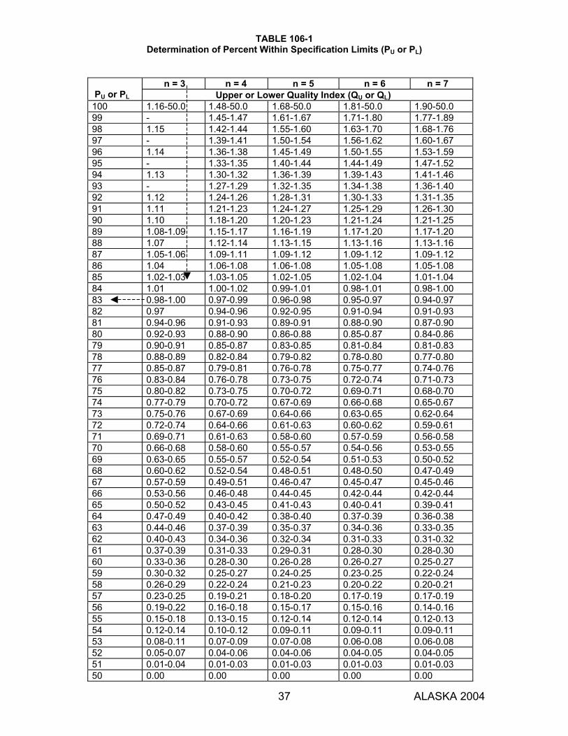
TABLE 106-1 Determination of Percent Within Specification Limits (PU or PL)
37 ALASKA 2004
n = 3 n = 4 n = 5 n = 6 n = 7
PU or PL Upper or Lower Quality Index (QU or QL) 100 1.16-50.0 1.48-50.0 1.68-50.0 1.81-50.0 1.90-50.0 99 - 1.45-1.47 1.61-1.67 1.71-1.80 1.77-1.89 98 1.15 1.42-1.44 1.55-1.60 1.63-1.70 1.68-1.76 97 - 1.39-1.41 1.50-1.54 1.56-1.62 1.60-1.67 96 1.14 1.36-1.38 1.45-1.49 1.50-1.55 1.53-1.59 95 - 1.33-1.35 1.40-1.44 1.44-1.49 1.47-1.52 94 1.13 1.30-1.32 1.36-1.39 1.39-1.43 1.41-1.46 93 - 1.27-1.29 1.32-1.35 1.34-1.38 1.36-1.40 92 1.12 1.24-1.26 1.28-1.31 1.30-1.33 1.31-1.35 91 1.11 1.21-1.23 1.24-1.27 1.25-1.29 1.26-1.30 90 1.10 1.18-1.20 1.20-1.23 1.21-1.24 1.21-1.25 89 1.08-1.09 1.15-1.17 1.16-1.19 1.17-1.20 1.17-1.20 88 1.07 1.12-1.14 1.13-1.15 1.13-1.16 1.13-1.16 87 1.05-1.06 1.09-1.11 1.09-1.12 1.09-1.12 1.09-1.12 86 1.04 1.06-1.08 1.06-1.08 1.05-1.08 1.05-1.08 85 1.02-1.03 1.03-1.05 1.02-1.05 1.02-1.04 1.01-1.04 84 1.01 1.00-1.02 0.99-1.01 0.98-1.01 0.98-1.00 83 0.98-1.00 0.97-0.99 0.96-0.98 0.95-0.97 0.94-0.97 82 0.97 0.94-0.96 0.92-0.95 0.91-0.94 0.91-0.93 81 0.94-0.96 0.91-0.93 0.89-0.91 0.88-0.90 0.87-0.90 80 0.92-0.93 0.88-0.90 0.86-0.88 0.85-0.87 0.84-0.86 79 0.90-0.91 0.85-0.87 0.83-0.85 0.81-0.84 0.81-0.83 78 0.88-0.89 0.82-0.84 0.79-0.82 0.78-0.80 0.77-0.80 77 0.85-0.87 0.79-0.81 0.76-0.78 0.75-0.77 0.74-0.76 76 0.83-0.84 0.76-0.78 0.73-0.75 0.72-0.74 0.71-0.73 75 0.80-0.82 0.73-0.75 0.70-0.72 0.69-0.71 0.68-0.70 74 0.77-0.79 0.70-0.72 0.67-0.69 0.66-0.68 0.65-0.67 73 0.75-0.76 0.67-0.69 0.64-0.66 0.63-0.65 0.62-0.64 72 0.72-0.74 0.64-0.66 0.61-0.63 0.60-0.62 0.59-0.61 71 0.69-0.71 0.61-0.63 0.58-0.60 0.57-0.59 0.56-0.58 70 0.66-0.68 0.58-0.60 0.55-0.57 0.54-0.56 0.53-0.55 69 0.63-0.65 0.55-0.57 0.52-0.54 0.51-0.53 0.50-0.52 68 0.60-0.62 0.52-0.54 0.48-0.51 0.48-0.50 0.47-0.49 67 0.57-0.59 0.49-0.51 0.46-0.47 0.45-0.47 0.45-0.46 66 0.53-0.56 0.46-0.48 0.44-0.45 0.42-0.44 0.42-0.44 65 0.50-0.52 0.43-0.45 0.41-0.43 0.40-0.41 0.39-0.41 64 0.47-0.49 0.40-0.42 0.38-0.40 0.37-0.39 0.36-0.38 63 0.44-0.46 0.37-0.39 0.35-0.37 0.34-0.36 0.33-0.35 62 0.40-0.43 0.34-0.36 0.32-0.34 0.31-0.33 0.31-0.32 61 0.37-0.39 0.31-0.33 0.29-0.31 0.28-0.30 0.28-0.30 60 0.33-0.36 0.28-0.30 0.26-0.28 0.26-0.27 0.25-0.27 59 0.30-0.32 0.25-0.27 0.24-0.25 0.23-0.25 0.22-0.24 58 0.26-0.29 0.22-0.24 0.21-0.23 0.20-0.22 0.20-0.21 57 0.23-0.25 0.19-0.21 0.18-0.20 0.17-0.19 0.17-0.19 56 0.19-0.22 0.16-0.18 0.15-0.17 0.15-0.16 0.14-0.16 55 0.15-0.18 0.13-0.15 0.12-0.14 0.12-0.14 0.12-0.13 54 0.12-0.14 0.10-0.12 0.09-0.11 0.09-0.11 0.09-0.11 53 0.08-0.11 0.07-0.09 0.07-0.08 0.06-0.08 0.06-0.08 52 0.05-0.07 0.04-0.06 0.04-0.06 0.04-0.05 0.04-0.05 51 0.01-0.04 0.01-0.03 0.01-0.03 0.01-0.03 0.01-0.03 50 0.00 0.00 0.00 0.00 0.00
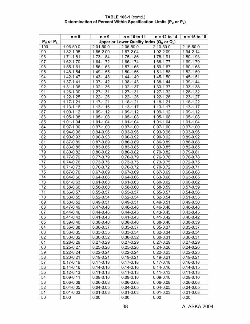
TABLE 106-1 (contd.) Determination of Percent Within Specification Limits (PU or PL)
38 ALASKA 2004
n = 8 n = 9 n = 10 to 11 n = 12 to 14 n = 15 to 18
PU or PL Upper or Lower Quality Index (QU or QL) 100 1.96-50.0 2.01-50.0 2.05-50.0 2.10-50.0 2.15-50.0 99 1.82-1.95 1.85-2.00 1.87-2.04 1.92-2.09 1.94-2.14 98 1.71-1.81 1.73-1.84 1.75-1.86 1.78-1.91 1.80-1.93 97 1.62-1.70 1.64-1.72 1.66-1.74 1.68-1.77 1.69-1.79 96 1.55-1.61 1.56-1.63 1.57-1.65 1.59-1.67 1.60-1.68 95 1.48-1.54 1.49-1.55 1.50-1.56 1.51-1.58 1.52-1.59 94 1.42-1.47 1.43-1.48 1.44-1.49 1.45-1.50 1.45-1.51 93 1.37-1.41 1.37-1.42 1.38-1.43 1.38-1.44 1.39-1.44 92 1.31-1.36 1.32-1.36 1.32-1.37 1.33-1.37 1.33-1.38 91 1.26-1.30 1.27-1.31 1.27-1.31 1.27-1.32 1.28-1.32 90 1.22-1.25 1.22-1.26 1.22-1.26 1.22-1.26 1.23-1.27 89 1.17-1.21 1.17-1.21 1.18-1.21 1.18-1.21 1.18-1.22 88 1.13-1.16 1.13-1.16 1.13-1.17 1.13-1.17 1.13-1.17 87 1.09-1.12 1.09-1.12 1.09-1.12 1.09-1.12 1.09-1.12 86 1.05-1.08 1.05-1.08 1.05-1.08 1.05-1.08 1.05-1.08 85 1.01-1.04 1.01-1.04 1.01-1.04 1.01-1.04 1.01-1.04 84 0.97-1.00 0.97-1.00 0.97-1.00 0.97-1.00 0.97-1.00 83 0.94-0.96 0.94-0.96 0.93-0.96 0.93-0.96 0.93-0.96 82 0.90-0.93 0.90-0.93 0.90-0.92 0.90-0.92 0.89-0.92 81 0.87-0.89 0.87-0.89 0.86-0.89 0.86-0.89 0.86-0.88 80 0.83-0.86 0.83-0.86 0.83-0.85 0.83-0.85 0.82-0.85 79 0.80-0.82 0.80-0.82 0.80-0.82 0.79-0.82 0.79-0.81 78 0.77-0.79 0.77-0.79 0.76-0.79 0.76-0.78 0.76-0.78 77 0.74-0.76 0.73-0.76 0.73-0.75 0.73-0.75 0.72-0.75 76 0.71-0.73 0.70-0.72 0.70-0.72 0.70-0.72 0.69-0.71 75 0.67-0.70 0.67-0.69 0.67-0.69 0.67-0.69 0.66-0.68 74 0.64-0.66 0.64-0.66 0.64-0.66 0.63-0.66 0.63-0.65 73 0.61-0.63 0.61-0.63 0.61-0.63 0.60-0.62 0.60-0.62 72 0.58-0.60 0.58-0.60 0.58-0.60 0.58-0.59 0.57-0.59 71 0.56-0.57 0.55-0.57 0.55-0.57 0.55-0.57 0.54-0.56 70 0.53-0.55 0.52-0.54 0.52-0.54 0.52-0.54 0.51-0.53 69 0.50-0.52 0.49-0.51 0.49-0.51 0.49-0.51 0.49-0.50 68 0.47-0.49 0.47-0.48 0.46-0.48 0.46-0.48 0.46-0.48 67 0.44-0.46 0.44-0.46 0.44-0.45 0.43-0.45 0.43-0.45 66 0.41-0.43 0.41-0.43 0.41-0.43 0.41-0.42 0.40-0.42 65 0.39-0.40 0.38-0.40 0.38-0.40 0.38-0.40 0.38-0.39 64 0.36-0.38 0.36-0.37 0.35-0.37 0.35-0.37 0.35-0.37 63 0.33-0.35 0.33-0.35 0.33-0.34 0.32-0.34 0.32-0.34 62 0.30-0.32 0.30-0.32 0.30-0.32 0.30-0.31 0.30-0.31 61 0.28-0.29 0.27-0.29 0.27-0.29 0.27-0.29 0.27-0.29 60 0.25-0.27 0.25-0.26 0.25-0.26 0.24-0.26 0.24-0.26 59 0.22-0.24 0.22-0.24 0.22-0.24 0.22-0.23 0.22-0.23 58 0.20-0.21 0.19-0.21 0.19-0.21 0.19-0.21 0.19-0.21 57 0.17-0.19 0.17-0.18 0.17-0.18 0.17-0.18 0.16-0.18 56 0.14-0.16 0.14-0.16 0.14-0.16 0.14-0.16 0.14-0.15 55 0.12-0.13 0.11-0.13 0.11-0.13 0.11-0.13 0.11-0.13 54 0.09-0.11 0.09-0.10 0.09-0.10 0.09-0.10 0.09-0.10 53 0.06-0.08 0.06-0.08 0.06-0.08 0.06-0.08 0.06-0.08 52 0.04-0.05 0.04-0.05 0.04-0.05 0.04-0.05 0.04-0.05 51 0.01-0.03 0.01-0.03 0.01-0.03 0.01-0.03 0.01-0.03 50 0.00 0.00 0.00 0.00 0.00
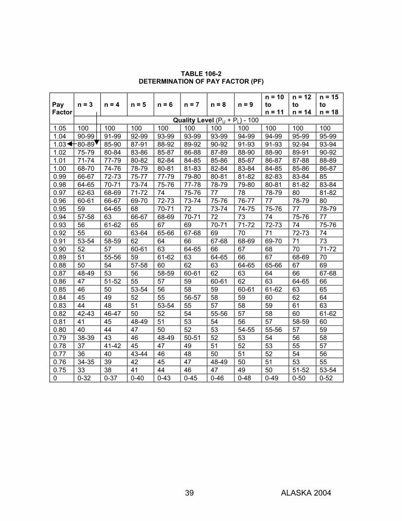
39 ALASKA 2004
TABLE 106-2 DETERMINATION OF PAY FACTOR (PF)
n = 3
n = 4
n = 5
n = 6
n = 7
n = 8
n = 9
n = 10 to n = 11
n = 12 to n = 14
n = 15 to n = 18
Pay Factor
Quality Level (PU + PL) - 100 1.05 100 100 100 100 100 100 100 100 100 100 1.04 90-99 91-99 92-99 93-99 93-99 93-99 94-99 94-99 95-99 95-99 1.03 80-89 85-90 87-91 88-92 89-92 90-92 91-93 91-93 92-94 93-94 1.02 75-79 80-84 83-86 85-87 86-88 87-89 88-90 88-90 89-91 90-92 1.01 71-74 77-79 80-82 82-84 84-85 85-86 85-87 86-87 87-88 88-89 1.00 68-70 74-76 78-79 80-81 81-83 82-84 83-84 84-85 85-86 86-87 0.99 66-67 72-73 75-77 77-79 79-80 80-81 81-82 82-83 83-84 85 0.98 64-65 70-71 73-74 75-76 77-78 78-79 79-80 80-81 81-82 83-84 0.97 62-63 68-69 71-72 74 75-76 77 78 78-79 80 81-82 0.96 60-61 66-67 69-70 72-73 73-74 75-76 76-77 77 78-79 80 0.95 59 64-65 68 70-71 72 73-74 74-75 75-76 77 78-79 0.94 57-58 63 66-67 68-69 70-71 72 73 74 75-76 77 0.93 56 61-62 65 67 69 70-71 71-72 72-73 74 75-76 0.92 55 60 63-64 65-66 67-68 69 70 71 72-73 74 0.91 53-54 58-59 62 64 66 67-68 68-69 69-70 71 73 0.90 52 57 60-61 63 64-65 66 67 68 70 71-72 0.89 51 55-56 59 61-62 63 64-65 66 67 68-69 70 0.88 50 54 57-58 60 62 63 64-65 65-66 67 69 0.87 48-49 53 56 58-59 60-61 62 63 64 66 67-68 0.86 47 51-52 55 57 59 60-61 62 63 64-65 66 0.85 46 50 53-54 56 58 59 60-61 61-62 63 65 0.84 45 49 52 55 56-57 58 59 60 62 64 0.83 44 48 51 53-54 55 57 58 59 61 63 0.82 42-43 46-47 50 52 54 55-56 57 58 60 61-62 0.81 41 45 48-49 51 53 54 56 57 58-59 60 0.80 40 44 47 50 52 53 54-55 55-56 57 59 0.79 38-39 43 46 48-49 50-51 52 53 54 56 58 0.78 37 41-42 45 47 49 51 52 53 55 57 0.77 36 40 43-44 46 48 50 51 52 54 56 0.76 34-35 39 42 45 47 48-49 50 51 53 55 0.75 33 38 41 44 46 47 49 50 51-52 53-54 0 0-32 0-37 0-40 0-43 0-45 0-46 0-48 0-49 0-50 0-52

SECTION 106
40 ALASKA 2004
106-1.04 PLANT INSPECTION. The Department may periodically inspect manufacturing methods, manufactured lots and materials at the source of production. The Department may approve, conditionally approve, or reject them. The Contractor shall: 1. Notify the Department of the production and fabrication schedule at least 30 days before beginning
work on any item requiring inspection, and notify the Department 48 hours before beginning production or fabrication;
2. Give the inspector full and safe access to all parts of the plant used to manufacture or produce materials; and
3. Cooperate fully and assist the inspector during the inspection. Materials may be rejected if the Department requests a plant inspection and the materials are produced or fabricated without a plant inspection. The materials may be tested at any time before final acceptance, whether in place or not, and whether approved at a plant inspection or not. If the materials do not meet Contract specifications, they may be rejected and ordered removed under Subsection 105-1.11. If rejected materials are incorporated into the project, the Department may require those materials to be removed and replaced at the Contractor's expense under Subsection 105-1.11. 106-1.05 CERTIFICATES OF COMPLIANCE. The Engineer may authorize the use of certain materials or assemblies based on a manufacturer's certificate of compliance. The certificate must state that the material or assembly fully complies with Contract requirements, include the project name and number, and be signed by the manufacturer. The certificate must accompany each lot of the materials or assemblies delivered to the project and must clearly identify the lot. The Contractor shall submit a manufacturer's certificate of compliance, as required, for each item listed on the Materials Certification List (MCL) included in the Contract documents. The Contractor shall submit additional manufacturer’s certificates of compliance if required by the Contract or by the Engineer. Materials or assemblies incorporated into the project on the basis of a manufacturer’s certificate of compliance may be tested at any time, whether in place or not, and, if they do not meet Contract specifications, they may be rejected and ordered removed under Subsection 105-1.11. The Engineer may refuse permission to incorporate materials or products into the project based on a manufacturer’s certificate of compliance that does not meet specifications. 106-1.06 STORAGE OF MATERIALS. Materials shall be stored to preserve their quality and fitness for the work, and so they can be readily inspected. Materials inspected before storage may be inspected again, before or after being incorporated into the project. The Contractor shall: 1. Use only approved portions of the project site for storage of materials and equipment or plant
operations; 2. Provide any additional space needed for such purposes without extra compensation; 3. Restore Department-owned or controlled storage and plant sites to their original condition without
extra compensation; 4. Obtain the landowner's or lessee’s written permission before storing material on private property, and
furnish copies of the permission to the Engineer, if requested; and 5. Restore privately owned or leased storage sites, without extra compensation from the Department, to
their original condition or as agreed to between the Contractor and the private owner. 106-1.07 DEPARTMENT-FURNISHED MATERIAL. Material furnished by the Department will be made available to the Contractor at a state yard or delivered at the locations specified in the Special Provisions. The Contractor shall include the cost of handling and placing all materials after they are delivered in the Contract price for the item in connection with which they are used. The Contractor is responsible for all material delivered to the Contractor. Deductions will be made from any monies due the Contractor to make good shortages and deficiencies from any cause whatsoever, for any damage that may occur after delivery, and for demurrage charges.
41 ALASKA 2004
SECTION 107
LEGAL RELATIONS AND RESPONSIBILITY TO PUBLIC
107-1.01 LAWS TO BE OBSERVED. The Contractor shall keep fully informed of, observe, and comply with all federal, state, and local laws, ordinances, and regulations, and all orders and decrees of bodies or tribunals having any jurisdiction or authority, that in any manner affect those engaged or employed on the work or which in any way affect the conduct of the work. The Contractor and the Surety shall defend, indemnify, and hold harmless the state and its representatives against any claim or liability related to violations of any laws, regulations or decrees by the Contractor, the Contractor's agents, the Contractor's employees, a subcontractor at any tier, or a supplier or service provider. The Contractor has the affirmative duty to keep informed of and comply with all laws. The Contractor is not entitled to and shall not rely on any Department employee's interpretation, whether oral or written, of any law, ordinance, or regulation. 107-1.02 PERMITS, LICENSES, AND TAXES. The terms, conditions, and stipulations in permits obtained either by the Department or by the Contractor are made a part of this Contract. The Department will: 1. Secure permits and licenses that the Department determines are required for the construction
of the proposed project, and the use of mandatory sources, designated sources and designated waste disposal areas for the proposed project; and
2. Modify Department-acquired permits during the performance of the contract, if deemed necessary by the Engineer.
The Contractor shall: 1. Acquire any permits and licenses required to complete the project that are not acquired by
the Department; 2. Provide qualified professionals to collect data or perform studies necessary to acquire
permits for the use of sites not previously permitted; 3. Give all notices required for the prosecution of the work; 4. Abide by all permits and licenses whether acquired by the Department or by the Contractor; 5. Notify the Engineer promptly if any activity cannot be performed as specified in the permits,
and cease conducting the activity until permit modifications or any required additional permits are obtained;
6. Obtain modifications to permits acquired by the Contractor; 7. Pay all charges, fees and taxes; and 8. Provide proof of payment of all taxes before the Department makes final payment. In addition, before using an area not previously permitted for use by the Contract, the Contractor shall: 1. Contact all government agencies having possible or apparent permit authority over that area; 2. Obtain all required permits and licenses from those agencies; 3. Obtain permission from any property owners or lessees with an interest in the property; and 4. Provide all of the following to the Engineer:
a. All permits or clearances necessary to use the site for its intended purpose(s); b. A written statement that all permits or clearances necessary have been obtained; c. Written evidence that the Contractor has contacted all of the relevant agencies and that
no additional permits are required on the part of the Contractor, including at a minimum the name of the agency and staff person contacted, the date contacted, and result of coordination; and
d. A plan that identifies how the site will be finally stabilized and protected.
SECTION 107
42 ALASKA 2004
The Engineer may reject a proposed site if the Contractor fails to provide any of the above information or to demonstrate that a proposed site can be finally stabilized to eliminate future adverse impacts on natural resources and the environment. 107-1.03 PATENTED DEVICES, MATERIALS AND PROCESSES. If the Contractor employs any design, device, material, or process covered by patent, trademark, or copyright, the Contractor shall obtain and provide the Engineer with a copy of a suitable legal agreement with the patentee or owner. The Contractor and the Surety shall defend, indemnify, and hold harmless the state and its representatives and any affected third party or political subdivision from any claim, cause of action, and damages for infringement arising from or relating to the Contractor's use of a patented design, device, material, process, trademark, or copyright. 107-1.04 WAGE RATES. The Contractor and all subcontractors shall pay the current prevailing rate of wages as per AS 36.05.010 and this Contract. On federally funded projects the Contractor and all subcontractors shall pay the higher of the appropriate wage rates published by the Alaska Department of Labor and the U.S. Department of Labor, for each individual job classification. The Contractor and all subcontractors shall file certified payroll with the Alaska Department of Labor and Workforce Development (DOLWD) and with the Engineer for all work performed on the project. Before beginning work the Contractor shall file a Notice of Work with DOLWD and pay all required fees. After finishing work the Contractor shall file a Notice of Completion with DOLWD and pay all additional fees required by increases in the Contract amount. 107-1.05 FEDERAL AID PROVISIONS. When the United States government pays all or any portion of the cost of a project, the Contractor shall observe all federal laws, rules, and regulations applicable to the project. The Contractor shall allow appropriate federal officials access to inspect the work. The federal government is not a party to the Contract. Federal inspections will not form the basis for any claim for interference with the rights of the Contract parties. 107-1.06 SANITARY, HEALTH, AND SAFETY PROVISIONS. The Contractor shall provide and maintain neat and sanitary accommodations for employees that meet all federal, state and local requirements. The Contractor shall comply with federal, state, and local laws, rules, and regulations concerning construction safety and health standards, including U.S. Mine Safety and Health Administration rules when the project includes pit or quarry operations. The Contractor shall not expose the public to, or require any workers to work under, conditions that are unsanitary, hazardous, or dangerous to health or safety. The Contractor is responsible for ensuring all workers are adequately protected. The Contractor shall have a safety and health management program that complies with AKOSH requirements, and includes: 1. A worksite hazard analysis; 2. A hazard prevention and control plan including personal protective equipment and safe work
procedures required for specific tasks; 3. New employee training and periodic worker training regarding safety and health; 4. Regular safety meetings with written documentation of attendance, safety topics discussed,
worker safety complaints, and corrective actions taken; and 5. A designated safety officer, employed by the Contractor, who monitors the construction site
and is responsible for implementing the safety and health management program.
SECTION 107
43 ALASKA 2004
The Contractor shall defend, indemnify and hold harmless the State of Alaska from all claims, causes of action and judgments arising from or relating to the Contractor’s failure to comply with any applicable federal, state or local safety requirement, regulation or practice, whether or not listed above. 107-1.07 ARCHAEOLOGICAL OR HISTORICAL DISCOVERIES. When the Contractor's operation encounters prehistoric artifacts, burials, remains of dwelling sites, paleontological remains, shell heaps, land or sea mammal bones, tusks, or other items of historical significance, the Contractor shall: 1. Immediately cease operations at the site of the find; 2. Immediately notify the Engineer of the find; and 3. Not disturb or remove the finds or perform further operations at the site of the finds until
directed by the Engineer. The Engineer will issue an appropriate Change Order if the Engineer orders suspension of the Contractor's operations or orders the Contractor to perform extra work in order to protect an archaeological or historical find. 107-1.08 RAILWAY-HIGHWAY PROVISIONS. The Contractor shall conduct all operations on or near a railroad according to the Contract, any contract between the Department and the railroad, and any permits issued by the railroad. The Department shall obtain permits for hauling materials across railroad tracks at locations specified in the Contract. If the Contractor desires additional crossings, the Contractor shall obtain any required permits at the Contractor's expense. 107-1.09 CONSTRUCTION OVER OR ADJACENT TO WATERS. The Contractor shall fully comply with all laws, regulations and permits issued by agencies of the United States and the State of Alaska when working in, over or adjacent to wetlands, tidelands, anadromous fish streams, eagle nests, navigable waters, or coastal waters. The Contractor shall ensure that all work in, over or adjacent to navigable waters is conducted so that free navigation of the waterways is not obstructed and that existing navigable depths are not impaired, except as allowed by the U.S. Coast Guard and the U.S. Army Corps of Engineers. 107-1.10 USE OF EXPLOSIVES. The Contractor shall obey all laws, regulations and permits applicable to using, handling, loading, transporting, or storing explosives. When using explosives, the Contractor shall take utmost care not to endanger life, property, new construction, or existing portions of the project and facilities that are to remain in place after the project is complete. The Contractor shall provide notice to property owners, the traveling public, and utility companies in the vicinity before using explosives. The Contractor shall provide notice to the Federal Aviation Administration when required by law. The Contractor shall notify police and fire authorities in the vicinity before transporting or using explosives. The Contractor shall provide notice sufficiently in advance to enable all potentially affected parties to take whatever steps they may deem necessary to protect themselves and their property from injury or damage. The Contractor is liable for all property damage, injury, or death resulting from the use of explosives on the project. The Contractor shall indemnify, hold harmless, and defend the State of Alaska from all claims related to the use of explosives on the project, including claims from government agencies alleging that explosives were handled, loaded, transported, used, or stored improperly.

SECTION 107
44 ALASKA 2004
107-1.11 PROTECTION AND RESTORATION OF PROPERTY AND LANDSCAPE. 1. Property marks. The Contractor shall:
a. Be responsible for and protect from disturbance all land monuments and property marks until the Engineer has approved the witnessing or otherwise referenced their locations; and
b. Not move such monuments or marks without the Engineer's approval. 2. Damage to property. The Contractor shall:
a. Be responsible for all damage to public or private property resulting from any act, omission, neglect, or misconduct in the manner or method of executing the work;
b. Be responsible for all damage to public or private property resulting from defective work or materials at any time, before, during, or after project completion; and
c. Restore all such damaged property to a condition similar or equal to that existing before the damage occurred, at no additional cost to the Department.
3. Protection of natural resources. The Contractor shall:
a. Conduct work in a manner that minimizes disturbance to and protects natural resources in compliance with all federal, state, and local laws and regulations;
b. When working near designated wetlands, as defined by the Corps of Engineers, place no fill, nor operate equipment outside the permitted area;
c. When working in or near designated anadromous fish streams, as defined by AS 41.14.840 and .870, place no fill or dredge material, nor operate equipment, within or on the banks of the stream (including fording) except as permitted by the State Fish Habitat Permit issued for the project; and
d. Not refuel and service equipment within 100 feet of wetlands and/or other water bodies. 4. Hazardous materials. Hazardous materials include but are not limited to petroleum products,
oils, solvents, paints, lead based paints, asbestos, and chemicals that are toxic, corrosive, explosive, or flammable. Except as otherwise specified in this Contract, the Contractor shall: a. Not excavate, nor use for fill, any material at any site suspected of or found to contain
hazardous materials or petroleum fuels; b. Not raze and remove, or dispose of structures that contain asbestos or lead-based
paints; c. Not stockpile, nor dispose of, any material at any site suspected of or found to contain
hazardous materials or petroleum; d. Report immediately to the Engineer any known or suspected hazardous material
discovered, exposed, or released into the air, ground, or water during construction of the project;
e. Report any containment, cleanup, or restoration activities anticipated or performed as a result of such release or discovery;
f. Handle and dispose of hazardous material with properly trained and licensed personnel who follow an approved Hazardous Material Control Plan as per Section 641.
5. Protected areas. The Contractor shall not use land from any park, recreation area, wildlife or
waterfowl refuge, or any historical site located inside or outside of the project limits for excess fill disposal, staging activities, equipment or material storage, or for any other purposes unless permitted by the Contract or unless all permits and clearances necessary for such work have been obtained by the Contractor as detailed in Subsection 107-1.02.
6. Solid waste. The Contractor shall remove all debris, trash, and other solid waste from the
project site as soon as possible and in accordance with the Alaska Department of Environmental Conservation Solid Waste Program.

SECTION 107
45 ALASKA 2004
107-1.12 FOREST PROTECTION. The Contractor shall: 1. Comply with all laws and regulations of the United States and the State of Alaska, local
governments, or other authorities governing the protection of forests and the carrying out of work within forests;
2. Keep forest areas in an orderly condition; 3. Dispose of all refuse and obtain permits for the construction and maintenance of all
construction camps, stores, warehouses, residences, latrines, cesspools, septic tanks, and other structures in accordance with the requirements of the supervising authorities;
4. Take all reasonable precautions to prevent and suppress forest fires; 5. Require workers and subcontractors, both independently and at the request of officials, to do
all reasonably within their power to prevent and suppress and to assist in preventing and suppressing forest fires; and
6. Make every possible effort to notify the appropriate forestry agency at the earliest moment of the location and extent of any forest fire.
107-1.13 RESPONSIBILITY FOR DAMAGE CLAIMS. The Contractor shall indemnify, hold harmless, and defend the State of Alaska and its agents and employees from any and all claims or actions for injuries or damages whatsoever sustained by any person or property that arise from or relate to, directly or indirectly, the Contractor's performance of the Contract; however, this provision has no effect if, but only if, the sole proximate cause of the injury or damage is the Department’s negligence. This Contract does not create a third party benefit to the public or any member of the public, nor does it authorize any person or entity not a party to this Contract to maintain a suit based on this Contract or any term or provision of the Contract, whether for personal injuries, property damage, or any other claim or cause of action. 107-1.14 OPENING SECTIONS OF THE PROJECT TO TRAFFIC. The Engineer may, at their discretion, order the Contractor to open sections of the work to traffic prior to completion of the entire project. Openings under this section shall not constitute (a) acceptance of the opened sections or any other part of the work or (b) a waiver of any other provision of the Contract. The Engineer may establish a time period for completing any features of the opened section of work that are behind schedule. The Contractor shall: 1. Maintain the opened portions of the work without additional compensation; 2. Perform all necessary repairs or renewals on the opened sections of the work without
additional compensation; and 3. Conduct the remainder of the work with minimum interference to traffic. 107-1.15 CONTRACTOR'S RESPONSIBILITY FOR WORK. The Contractor shall be responsible for implementing all preventative measures necessary to protect, prevent damage, and repair damage to the work from all causes at no additional cost to the Department. This duty continues from the date construction begins until the date specified in a letter of Substantial Completion or Partial Acceptance of a specific section of the project. Where there is a Partial Acceptance, the duty ends only as to the accepted portion of the work. This duty continues during periods of suspended work, except in specific sections the Department has agreed to maintain under Subsection 643-3.07. The Contractor shall rebuild, repair, restore, and make good all losses or damages to any portion of the work including that caused by vandalism, theft, accommodation of public traffic, and weather. The Department will only be responsible for loss or damage due to unforeseeable causes beyond the control of and without the Contractor’s fault or negligence, such as Acts of God, the public enemy, and governmental authorities.

SECTION 107
46 ALASKA 2004
In case of suspension of work from any cause, the Contractor shall take such precautions as may be necessary to prevent damage to the work or facilities affected by the work. This will include providing for drainage and erecting any necessary temporary structures, signs, or other facilities and maintaining all living material such as plantings, seedings, and soddings. 107-1.16 RESERVED. 107-1.17 FURNISHING RIGHT-OF-WAY. The Department will secure all necessary right-of-way or property in advance of construction. Any exceptions will be indicated in the Contract. 107-1.18 PERSONAL LIABILITY OF PUBLIC OFFICIALS. There shall be no liability upon the Engineer and their authorized representatives, either personally or as officials of the state, in carrying out any of the provisions of this Contract, or in exercising any power or authority granted to them by or within the scope of the Contract, it being understood that in all such matters the Engineer and their authorized representatives act solely as agents and representatives of the State. The Contractor shall bring no suit related to or arising under this Contract naming as defendants any State officer, employee or representative in either their personal or official capacities, and shall include a prohibition to that effect in all subcontracts entered into for this Project. 107-1.19 NO WAIVER OF LEGAL RIGHTS. The Department shall not be precluded nor estopped by any measurement, estimate, or certificate made either before or after the completion and acceptance of the work and payment, from showing the true amount and character of the work performed and materials furnished by the Contractor, nor from showing that any measurement, estimate, or certificate is untrue or is incorrectly made, nor that the work or materials do not in fact conform to the Contract. The Department shall not be precluded nor estopped, notwithstanding any measurement, estimate, or certificate and payment, from recovering from the Contractor or the Contractor’s Sureties, or both, such damages as it may sustain by reason of the Contractor's failure to comply with the terms of the Contract. Neither the acceptance by the Department, or by any representative of the Department, nor any payment for or acceptance of the whole or any part of the work, nor any extension of time, nor any possession taken by the Department, shall operate as a waiver by the Department of any portion of the Contract or of any right of the Department to damages. A waiver by the Department of any breach of the Contract shall not be held to be a waiver of any other subsequent breach. 107-1.20 GRATUITY AND CONFLICT OF INTEREST. The Contractor shall not extend any loan, gratuity, or gift of money of any form whatsoever to any employee of the Department, nor will the Contractor rent or purchase any equipment or materials from any employee of the Department or to the best of the Contractor’s knowledge from any agent of any employee of the Department. The Contractor shall execute and furnish the Department an affidavit certifying that the Contractor has complied with this section before final acceptance.

47 ALASKA 2004
SECTION 108
PROSECUTION AND PROGRESS
108-1.01 SUBLETTING OF CONTRACT. The Contractor shall obtain the Department’s written approval before the Contractor or any subcontractor sublets, sells, transfers, assigns, or otherwise disposes of the Contract or any portion of the Contract. The Contractor shall perform, with the Contractor's own organization, work amounting to at least 30 percent of the difference between the original Contract price and the price of designated Specialty Items. For the purpose of this Subsection, work is defined as the dollar value of the services, equipment, materials, and manufactured products furnished under the Contract. The Engineer will determine the value of the subcontracts based on Contract unit prices or upon reasonable value, if entire items are not subcontracted. The Department’s consent to the subletting, sale, transfer, assignment, or disposal of all or a part of the Contract shall not relieve the Contractor and the Surety of responsibility for fulfillment of the Contract or for liability under the bonds regardless of the terms of the transfer or sublet approvals. 1. The Contractor shall ensure that for all subcontracts submitted:
a. The subcontractors have submitted a Bidder Registration (Form 25D-6); b. The required prompt payment provisions of AS 36.90.210 are included in the
subcontracts; c. The Department is furnished with three copies of subcontracts for approval, signed and
dated by both parties and including prices for the subcontracted work; and d. The subcontractors pay current prevailing rate of wages as per Subsection 107-1.04 and
file certified payrolls with the Engineer and DOLWD for all work performed on the project. 2. The following will be considered as subcontracting, unless performed by the Contractor:
a. Roadside Production. Roadside production of crushed stone, gravel, and other materials with portable or semi-portable crushing, screening, or washing plants set up or reopened in the vicinity of the project to supply materials for the project, including borrow pits used exclusively or nearly exclusively for the project.
b. Temporary Plants. Production of aggregate mix, concrete mix, asphalt mix, other materials, or fabricated items from temporary batching plants, temporary mixing plants, or temporary factories that are set up or reopened in the vicinity of the project to supply materials exclusively or nearly exclusively for the project.
c. Hauling. Hauling from the project to roadside production, temporary plants, or commercial plants, from roadside production or temporary plants to the project, from roadside production or temporary plants to commercial plants, and all other hauling not specifically excluded in this subsection.
d. Other Contractors. All other contractors working on the project site under contract with the Contractor are considered subcontractors unless specifically excluded in this subsection.
3. The following will not be considered as subcontracting, but the Contractor shall comply with
the prompt payment provisions of AS 36.90: a. Commercial Plants. The purchase of sand, gravel, crushed stone, crushed slag, batched
concrete aggregates, ready-mixed concrete, asphalt paving mix, and any other material or fabrication produced at and furnished from established and recognized commercial plants that sell to both public and private purchasers.

SECTION 108
ALASKA 2004 48
b. Hauling. Delivery of materials from a commercial plant to a different commercial plant, and delivery from a commercial plant to the project site by vehicles owned and operated by the commercial plants or by commercial freight companies that have a contract with the commercial plant. Commercial freight companies are trucking or hauling companies that deliver multiple types of materials to multiple clients, both public and private, on an established route and on a recurrent basis.
c. Contractors' General Business. Work within permanent home offices, branch plants, fabrication plants, tool yards, and other establishments that are part of a contractor's or subcontractor's general business operations.
4. Owner-Operators. Hauling of materials for the project by bona fide truck owner-operators who are listed as such on the certified payroll of the Contractor or approved subcontractor is not considered subcontracting for purposes of AS 36.30.115.
The Contractor shall ensure that the required prompt payment provisions of AS 36.90.210 are included in contracts with owner-operators.
The Contractor shall collect and maintain at the project site current and valid copies of the following to prove that each trucker listed is a bona fide owner-operator: a. Alaska Driver's License with appropriate CDL class and endorsements; b. Business license for trucking with supporting documents that list the driver as the
business owner or corporate officer; c. Documents showing the driver's ownership interest in the truck, including copies of:
(1) Truck registration; and (2) Lease (if truck is not registered in driver's name or in the name of the driver's
company).
The Contractor shall maintain legible copies of these records for a period of at least three years after final acceptance of the project.
Owner-operators must qualify as independent contractors under the current Alaska Department of Labor’s criteria. Owner-operators may be required to show: a. The owner-operator's right to control the manner in which the work is to be performed; b. The owner-operator's opportunity for profit or loss depending upon their managerial skill; c. The owner-operator's investment in equipment or materials required for their task, or the
employment of helpers; d. Whether the service rendered requires a special skill; e. The degree of permanence of the working relationship; and f. Whether the service rendered is an integral part of the owner-operator's business.
The status of owner-operators is subject to evaluation throughout the project period. If the criteria for an independent contractor are not met, the Contractor shall submit amended payrolls listing the driver as an employee subject to all labor provisions of the Contract. The Contractor shall issue each owner-operator a placard in a form approved by the Engineer that identifies both the truck driver and the vehicle. The placard shall be prominently displayed on the vehicle so that it is visible to scale operators and inspectors.
Not withstanding the Department’s definitions of contracting and subcontracting, the Contractor shall be responsible for determining and complying with all federal and state laws and regulations regarding contracting, subcontracting, and payment of wages. The Contractor shall promptly pay any fines or penalties assessed for violations of those laws and regulations, and shall promptly comply with the directives of any government agency having jurisdiction over those matters.
SECTION 108
ALASKA 2004 49
108-1.02 NOTICE TO PROCEED. The Department will issue a Notice to Proceed authorizing construction to begin and indicating the date when Contract time will begin. The Contractor shall not begin construction before the effective date of the Notice to Proceed. The Department will, in its sole discretion, refuse to pay for construction begun before the effective date of the Notice to Proceed. The Contractor shall notify the Engineer at least 48 hours before construction begins at the project site. 108-1.03 PROSECUTION AND PROGRESS. The Contractor shall meet with the Engineer at the regional construction office for a preconstruction conference before beginning construction. The Contractor shall submit the following documents to the Engineer at least five working days before the preconstruction conference: 1. A progress schedule, in a format acceptable to the Engineer, showing the order in which the
Contractor proposes to carry out the work and the contemplated dates on which the Contractor and the subcontractors will start and finish each of the salient features of the work, including any scheduled periods of shutdown. The schedule shall indicate the anticipated hours of operation and any anticipated periods of multiple-shift work.
2. A list showing anticipated dates for procurement of materials and equipment, ordering of
articles of special manufacture, furnishing of plans, drawings and other data required under Subsection 105-1.02 and for other events such as inspection of structural steel fabrication.
3. A list showing all proposed subcontractors and material suppliers. 4. A Construction Phasing plan, as required under Subsection 643-1.05. 5. A Storm Water Pollution Prevention Plan and a Hazardous Material Control Plan, with the line
of authority and designated field representatives, as required under Section 641. 6. A letter designating the Contractor's Project Superintendent, defining that person's
responsibility and authority, and providing a specimen signature. 7. A letter designating an Equal Employment Opportunity Officer and a Disadvantaged Business
Enterprise Officer, and designating those person’s responsibilities and authority. 8. A Quality Control Plan, as required under Subsection 106-1.03. 9. A letter designating a Safety Officer, and designating that person’s responsibilities and
authority. The Contractor shall provide adequate materials, labor and equipment to ensure the completion of the project according to the Plans and Specifications. The work shall be performed as vigorously and as continuously as weather conditions or other interferences may permit. The Contractor shall take into consideration and make due allowances at the Contractor’s expense for foreseeable delays and interruptions to the work such as unfavorable weather, frozen ground, equipment breakdowns, shipping delays, quantity overruns, utility work, permit restrictions, and other foreseeable delays and interruptions. The Contractor shall identify these allowances on the progress schedule. The Contractor shall adjust forces, equipment and work schedules as necessary to ensure completion of the work within the Contract time, and shall notify the Engineer at least 24 hours before resuming suspended operations. Upon a substantial change to the work schedule or when directed by the Engineer, the Contractor shall submit a revised progress schedule in the form required, including a written explanation for each revision made in the schedule or methods of operation.
SECTION 108
ALASKA 2004 50
The Engineer's review or approval of the documents, plans, and schedules provided by the Contractor under this section shall not change the Contract requirements, release the Contractor of the responsibility for successful completion of the work or relieve the Contractor of the duty to comply with applicable laws. The Engineer’s review or approval of schedules shall not indicate agreement with any assertions of delay or claims by the Contractor. It is the Contractor's responsibility to prepare and submit documents that satisfy all applicable contract requirements. By reviewing and approving the Contractor’s documents, the Department does not warrant that following the Contractor’s documents will result in successful performance of the work. The Department's failure to discover defects in the Contractor's documents, the assumptions upon which they are based or conditions that prevent the Contractor from performing the work as indicated in the documents will not entitle the Contractor to additional compensation or time. If the Contractor becomes aware of any act or occurrence that may form the basis of a claim for additional compensation or an extension of time, it must specifically advise the Engineer of these conditions in accordance with Subsection 105-1.17. 108-1.04 LIMITATION OF OPERATIONS. The Contractor shall not open up work to the detriment of work already started. The Contractor shall minimize interference with traffic within the project. The Contractor shall not stop or otherwise impede traffic outside the project limits without the Engineer's prior written permission. The Engineer may require the Contractor to finish a section of work in progress before starting additional sections if the Engineer determines it is necessary for the convenience of the public or the Department. 108-1.05 CHARACTER OF WORKERS, METHODS, AND EQUIPMENT. The Contractor shall employ sufficient labor and equipment to complete the work required under the Contract and to complete it on time. The Contractor shall ensure that all workers on the project have the skills and experience necessary to properly perform their assigned work. Workers engaged in special work or skilled work shall have sufficient experience in that work and in the operation of the equipment required to properly perform that work. The Contractor shall comply with any written order by the Engineer to remove workers, who, in the opinion of the Engineer, perform the work in an unskilled manner, who are intemperate or disorderly, or who jeopardize the safety of the public, other workers or Engineer’s personnel. The Contractor shall allow removed workers to return to the project only with the Engineer’s written permission. The Engineer may suspend the work if the Contractor fails to furnish suitable and sufficient personnel necessary to perform the work, or fails to remove any worker at the Engineer's order. The Contractor shall not use prisoner labor on the project. The Contractor shall use equipment of the appropriate size and mechanical condition to produce the specified quality and quantity of work by the means specified in the Contract, if any, and shall ensure that the equipment does not damage roadways or property. The Contractor shall ensure all equipment, materials, and articles incorporated into the work are new and of the specified quality, unless the Contract specifically permits otherwise. The Contractor shall provide the Engineer with a list of all powered equipment that will be used on the project, showing the make, model, year, capacity, horsepower, and related information. The Contractor shall update this list when equipment is added or removed from the work site, but need not update more frequently than weekly. When the methods and equipment to be used by the Contractor are not prescribed by the contract, the Contractor is free to use any method, means or equipment that is satisfactory to
SECTION 108
ALASKA 2004 51
produce the specified work in conformity with the Contract, except as provided above. At the request of the Engineer, the Contractor shall demonstrate that the method, means and equipment chosen will produce the work specified in the Contract in the time allowed under the Contract. The Contractor shall bear all costs and impacts associated with any means, methods and equipment chosen by the Contractor. No suggestion, statement or observation from the Engineer or other Department representatives shall alter this responsibility. If the Contract specifies a particular method, means or type of equipment for performance of the work, the Contractor must use that method, means or equipment unless the Contractor first requests, in writing, permission to alter the Contract requirement and receives prior written approval from the Engineer. 108-1.06 CONTRACT TIME, EXTENSION OF CONTRACT TIME AND SUSPENSION OF WORK. Contract time will be specified in Calendar Days or by specific Completion Date. 1. Calendar Days. When the contract time is specified on a calendar days basis, all work under
the Contract shall be completed within the number of calendar days specified. If no starting day is specified in the Contract, the count of Contract time begins on the day following receipt of the Notice to Proceed by the Contractor.
Calendar days shall continue to be counted against Contract time until and including the date of project completion. Calendar days shall not be counted during the period from November 1 through April 30, except for days that the Contractor is working on the project site.
2. Completion Date. When the contract time is specified on a completion date basis, all work
under the Contract shall be completed by the specified completion date. 3. Reasons for Suspension of Work and Extension of Contract Time. The Department may
order a suspension of work for any reason listed in Items 3a through 3p. The Department shall not pay additional compensation, but may extend Contract time only, if there are delays in the completion of controlling items of work from unforeseeable causes that are beyond the Contractor's control and are not the result of the Contractor's fault or negligence, including: a. Acts of God; b. Acts of the public enemy; c. Fires; d. Floods; e. Epidemics; f. Quarantine restrictions; g. Strikes; h. Freight embargoes; i. Unusually severe weather; j. In accordance with Subsection 105-1.06.4.d, delays by utility owners beyond completion
dates specified in the Special Provisions for relocating or adjusting utilities and related facilities; or
k. Delays of subcontractors, suppliers and fabricators from unforeseeable causes beyond the control of the subcontractors, suppliers or fabricators and that are not the fault of the subcontractors, suppliers or fabricators, including those causes listed in this Subparagraph 3, Items a through j.
No additional Contract time or additional compensation will be allowed due to delays caused by or suspensions ordered due to: l. Failure to correct unsafe conditions for the workers or the public; m. Adverse weather that is not unusually severe; n. Failure to carry out Contract provisions;

SECTION 108
ALASKA 2004 52
o. Failure to carry out orders given by the Engineer; or p. Failure to timely obtain materials, equipment, or services. The Contractor shall notify the Engineer as soon as the Contractor becomes aware of any act or occurrence that may form the basis of a request for a time extension under this section. The Contractor shall submit a request for a time extension to the Engineer within 10 days of the act or occurrence, and if an agreement is not reached, the Contractor may submit a Claim under Subsection 105-1.17. The time allowed in the Contract, as awarded, is based on performing the original estimated quantities of work set out in the bid schedule. An assertion that insufficient time was originally specified shall not constitute a valid reason for extension of contract time. If satisfactory fulfillment of the Contract requires extra work, the Department may extend Contract time on a basis commensurate with the amount and difficulty of the extra work, provided that the extra work is for a controlling item.
4. Suspension of Work. The Engineer will suspend work on the project, in whole or in part, for
such periods and for such reasons as the Engineer determines to be reasonable, necessary, in the public interest, or for the convenience of the Department.
a. The Engineer will issue a written order to suspend, delay, or interrupt all or any part of the
work. The Contractor shall not be compensated for the suspension, delay, or interruption if it is imposed for a reasonable time under the circumstances.
b. Unless another Contract section specifically provides otherwise, the Contractor will be
compensated by equitable adjustment for a suspension, delay, or interruption of the work only if:
(1) The period of suspension, delay, or interruption is for an unreasonable time under the
circumstances and another Contract section allows compensation in the event of a suspension, delay, or interruption of the work under the circumstances that actually caused the suspension, delay, or interruption; or
(2) The delay, suspension, or interruption results from the Department’s failure to fulfill a
contractual obligation to the Contractor within the time period specified in the Contract or, if no time period is specified, within a reasonable time.
c. No equitable adjustment will be made under this subsection for any suspension, delay, or
interruption of the work if the Contractor's performance would have been suspended, delayed, or interrupted by any other cause for which:
(1) The Department is not responsible under the Contract, including the Contractor's
fault or negligence; or
(2) An equitable adjustment is either provided for or excluded under any other section of this Contract.
d. Claims for equitable adjustments under this section shall be filed under Subsection 105-
1.17 except that:
(1) The Contractor must give written notice of intent to claim no later than 20 days after the event giving rise to the delay, suspension, or interruption; and
(2) The claim may not include any costs incurred more than 20 days before the
Contractor files the Contractor's written notice of intent to claim.

SECTION 108
ALASKA 2004 53
108-1.07 FAILURE TO COMPLETE ON TIME. For each calendar day that the work is not substantially complete after the expiration of the Contract time or the completion date has passed, the Engineer shall deduct the full daily charge corresponding to the original Contract amount shown in Table 108-1 from progress payments. For each calendar day that the work is substantially complete but the project is not complete, after the expiration of the Contract time or the completion date has passed, the Engineer shall deduct 20 percent of the daily charge corresponding to the original Contract amount shown in Table 108-1 from progress payments. If no money is due the Contractor, the Department may recover these sums from the Contractor, from the Surety, or from both. These are liquidated damages and not penalties. These charges shall reimburse the Department for its additional administrative expenses incurred due to the Contractor's failure to complete the work within the time specified.
TABLE 108-1
DAILY CHARGE FOR LIQUIDATED DAMAGES FOR EACH CALENDAR DAY OF DELAY
Original Contract Amount Daily Charge
From More Than To and Including $ 0 $ 100,000 $ 300
100,000 500,000 550 500,000 1,000,000 750
1,000,000 2,000,000 1,000 2,000,000 5,000,000 1,500 5,000,000 10,000,000 2,500 10,000,000 -------------- 3,000
Permitting the Contractor to continue work after the Contract time has elapsed or the completion date has passed does not waive the Department’s rights to collect liquidated damages under this section. 108-1.08 DEFAULT OF CONTRACT. The Contracting Officer will give a written Notice of Default to the Contractor and the Surety if the Contractor: 1. Fails to begin work under the Contract within the time specified; 2. Fails to perform the work with sufficient workers, equipment, or materials to ensure the
prompt completion of the work; 3. Performs the work unsuitably or neglects or refuses to remove materials or to replace
rejected work; 4. Discontinues the prosecution of the work; 5. Fails to resume work that has been discontinued within a reasonable time after notice to do
so; 6. Becomes insolvent except that if the Contractor declares bankruptcy, termination shall be in
accordance with the Federal Bankruptcy Code. In the event that the Contractor declares bankruptcy, the Contractor agrees that the Contract will be assumed by the Surety in a timely manner so as to complete the Contract by the date specified in the Contract;
7. Allows any final judgment to stand against the Contractor unsatisfied for a period of 60 days; 8. Makes an assignment for the benefit of creditors, without the consent of the Engineer; 9. Fails to comply with applicable minimum wage or civil rights requirements; 10. Is a party to fraud, deceit, misrepresentation, or malfeasance in connection with the Contract;
or 11. Fails to perform the work in an acceptable manner for any other cause whatsoever.

SECTION 108
ALASKA 2004 54
The written Notice of Default will include a notice to cure and will establish a date by which the cure must be completed. The Contracting Officer may allow more time to cure than originally stated in the Notice to Default if the Contracting Officer deems it to be in the best interests of the Department. Failure to cure the delay, neglect, or default within the time specified in the Contracting Officer’s Notice of Default authorizes the Department to terminate the contract. The Department will provide the Contractor and the Contractor's Surety with a written Notice of Termination.
After the Notice of Termination is issued, the Department may take over the work without further notice; may complete it by itself, by contract or otherwise; and may take possession of and use materials, appliances, equipment, or plant on the work site necessary for completing the work. The Department may transfer the obligation to perform the work from the Contractor to the Surety. In that event, the Surety shall submit its plan for completion of the work, including any contracts or agreements with third parties for completion, to the Department for approval before beginning work. The Surety must follow the Contract requirements for approval of subcontracts, except that the limitation on percent of work subcontracted will not apply. On receipt of the transfer notice, the Surety shall take possession of all materials, tools, equipment, and appliances at the work site, employ an appropriate work force, and complete the Contract work as specified. The Contract specifications and requirements shall remain in effect, except that the Department will make subsequent Contract payments directly to the Surety. The Contractor forfeits any right to claim for the work and is not entitled to receive any further balance of the amount to be paid under the Contract. The Contractor and the Contractor's Surety are jointly and severally liable for any damage to the Department resulting from the Contractor's delay, neglect, or default, whether or not the Department terminates the Contractor's right to prosecute the work. The Department's damages include any increased costs incurred by the Department in completing the work or paying for the work to be completed. The Department's rights and remedies are in addition to any other rights and remedies provided by law or under the Contract. If, after notice of termination of the Contractor's right to proceed under this clause, it is determined that the Contractor was not in default, or that the default was excusable, the rights and obligations of the parties will be determined under Subsection 108-1.09, Termination for Convenience. 108-1.09 TERMINATION FOR CONVENIENCE. 1. Notice. The Contracting Officer may terminate the Contract in whole or in part due to:
a. Executive Orders of the President of the United States or the Governor of the State of Alaska with respect to the prosecution of war or the interest of national defense, or any disaster declaration.
b. Restraining orders or injunctions by a court of competent jurisdiction affecting prosecution of the work based on acts or omissions of persons or agencies other than the Contractor.
c. Any reason determined by the Contracting Officer to be in the best interest of the Department.
The Contracting Officer will issue a written Notice of Termination to the Contractor. The Notice of Termination shall state the extent to which performance of work under the Contract is terminated, the effective date of the termination, and for which of the above-listed reasons the Contract is terminated.
SECTION 108
ALASKA 2004 55
2. Required Actions. Unless otherwise directed by the Contracting Officer, upon receipt of a Notice of Termination the Contractor shall immediately:
a. Stop work as directed in the Notice.
b. Place no further orders or subcontracts for materials, services, or facilities except as
approved to complete work not terminated.
c. Terminate all orders and subcontracts for the terminated work.
d. Accomplish either (1) or (2) below as directed by the Contracting Officer:
(1) Assign to the Department all right, title and interest in any terminated orders or subcontracts. The Contracting Officer will settle all claims on the terminated orders or subcontracts.
(2) Settle any outstanding liabilities and claims arising from termination of orders and
subcontracts. Settlements must be limited to costs allowed under this Section.
e. Submit to the Contracting Officer a list, certified as to quantity and quality, of all materials acquired or produced for incorporation into the project and that are properly allocable to the terminated portion of the project, exclusive of items disposed of under Subsection 108-1.09.2.f., below.
f. Dispose of materials in the Contractor’s possession or control that were acquired or produced but not incorporated into the project as of the termination date as directed by the Contracting Officer under either (1) or (2) below: (1) Transfer title and deliver the materials to the Department. The Department will pay for
the materials at the actual cost delivered to the project or storage site, including transportation charges, to which cost 15% will be added.
(2) Sell the materials. Credit will not have to be extended to prospective purchasers. The Contractor may acquire the materials if the Contracting Officer approves the sale price and the Contractor meets any other conditions prescribed by the Contracting Officer. At the sole discretion of the Contracting Officer, the proceeds of any sale, transfer, or disposition of materials may be: (1) applied to reduce any payments to be made by the Department under the Contract, (2) credited to the cost of the work, or (3) paid in any other manner as directed.
g. Deliver to the Department completed or partially completed plans, drawings, information, and other property required to be furnished under the Contract.
h. Take all necessary actions and comply with all directives to protect contract-related property in which the Department has or may acquire an interest.
i. Complete work not terminated.
The Contractor shall proceed immediately with performance of the above obligations notwithstanding any delay in determining or adjusting the amount of any item or reimbursable cost under this clause.
SECTION 108
ALASKA 2004 56
3. Claim. The Contractor shall submit any termination claim to the Contracting Officer within 90 days after the effective date of termination, unless the date for submitting a claim is extended in writing by the Contracting Officer.
a. Without duplication of any amount paid for under Subsection 108-1.09.2., the claim may
be for the total of:
(1) costs incurred in performing the terminated work from the date of Contract award to the effective date of the termination subject to the provisions of Subsection 108-1.09.3.b. regarding reimbursement of equipment costs and Subsection 108-1.09.3.c. regarding unallowable items.
(2) payments approved by the Contracting Officer under Subsection 108-1.09.2.d.(2) to
settle the termination claims of suppliers and subcontractors to the extent not covered under Subsection 108-1.09.3.a.(1).
(3) reasonably incurred costs for:
(a) accounting, legal, clerical, and other costs reasonably necessary for preparation
of the termination claim and settlement negotiations, excluding costs incurred after the date an appeal is filed with the Appeals Officer under Subsection 108-1.09.8.
(b) settling subcontractor and supplier claims, excluding the amounts of those
settlements paid under Subsection 108-1.09.3.a.(2). (4) reasonable profit on the costs included in Subsection 108-1.09.3.a(1) based on the
Contractor’s bid rate for profit or as determined under any other reasonable accounting method. However, if it appears that the Contractor would have sustained a loss on the entire Contract had it been completed, the Contracting Officer will allow no profit and will reduce the settlement to reflect the indicated rate of loss under Subsection 108-1.09.4. The Department will not pay profit on costs included in Subsections 108-1.09.3.a.(2) and 108-1.09.3.a.(3).
b. Equipment claims will be reimbursed as follows:
(1) Contractor-owned equipment usage, based on the Contractor’s ownership and
operating costs for each piece of equipment as determined from the Contractor’s accounting records. Do not base equipment claims on published rental rates.
(2) Idle time for Contractor-owned equipment, based on the Contractor’s internal
ownership and depreciation costs. Idle equipment time is limited to the actual period of time equipment is idle as a direct result of the termination, not to exceed 30 days. Operating expenses will not be included for payment of idle equipment time.
(3) Rented equipment, based on reasonable, actual rental costs. Equipment leased
under “capital leases” as defined in Financial Accounting Standard No. 13 will be considered Contractor-owned equipment. Equipment leased from an affiliate, division, subsidiary or other organization under common control with the Contractor will be considered Contractor-owned equipment, unless the affiliate, division, subsidiary or other organization has an established practice of leasing to unaffiliated lessees.
SECTION 108
ALASKA 2004 57
c. The following costs are not payable under a termination settlement agreement or Contracting Officer’s determination of the termination claim, or on appeal: (1) Loss of anticipated profits or consequential or compensatory damages (2) Unabsorbed home office overhead (also termed “General & Administrative Expense”)
related to ongoing business operations (3) Bidding and project investigative costs (4) Direct costs of repairing equipment to render it operable for use on the terminated
work
4. Adjustment for Loss. If the Contractor would have sustained a loss on the entire Contract had it been completed, the Department will not pay the Contractor more than the total of:
a. The amount due for termination claim costs under Subsection 108-1.09.3.a.(3); plus
b. The remainder of the total allowable claim amount due reduced by multiplying the
remainder by the ratio of (1) the total contract price to (2) the remainder plus the estimated cost to complete the entire Contract; minus
c. all disposal and other credits, all advance and progress payments and all other amounts previously paid under the Contract.
5. Deductions. In arriving at the amount due under this Subsection, the Department will deduct:
a. All previous payments made before termination;
b. Any claim which the Department may have against the Contractor;
c. The proceeds of the sale or transfer of any materials, supplies, or other items acquired for the terminated work and not otherwise recovered by or credited to the Department;
d. All partial payments made under this Section; and
e. Any adjustment for loss determined under Subsection 108-1.09.4.
6. Agreed Settlement. The Contractor shall make every effort to arrive at a claim settlement with the Contracting Officer that is fair to both parties, that reflects the reasonable and allocable incurred costs allowable under Subsection 108-1.09.3, that includes a profit under Subsection 108-1.09.3.a.(4) or, where appropriate, a loss adjustment under Subsection 108-1.09.4, and that takes into account the Contractor’s reasonable business judgment in performing the work.
The total settlement, whether determined under this Subsection 108-1.09.6 or under Subsection 108-1.09.7, exclusive of the costs listed in Subsection 108-1.09.3.a.(3), may not exceed the total contract price as reduced by previous payments made and the contract price of work not terminated. If an agreement is reached in whole or in part, the Department will amend the contract and will pay the agreed amount.
7. Determined Settlement. If the Contractor fails to submit a termination claim within the time
allowed, or if an agreement is not reached on the amount due, the Contracting Officer may determine in a Contracting Officer’s Decision, the amount due under Subsection 108-1.09 on the basis of information available to the Department.
8. Right of Appeal. The Contractor may appeal a Contracting Officer’s Decision within the time
and in the manner specified in Subsection 105-1.17.
SECTION 108
ALASKA 2004 58
9. Partial Payments. In the sole discretion of the Contracting Officer, the Department may make partial payments against costs incurred by the Contractor in connection with the terminated portion of the Contract. The sum of these partial payments will not exceed the Contracting Officer’s estimate of the total amount that will be due as a result of the termination. The estimate will be based on available information. The Contracting Officer may adjust the estimate as additional information becomes available. If the Contracting Officer orders an audit of the Contractor’s financial or project records, the Contracting Officer may decline to make partial payments until the audit is completed.
10. No Waiver of Rights. The termination of work by the Department does not affect or extinguish
any of the rights of the Department against the Contractor or the Contractor’s Surety then existing or which may thereafter accrue. Any retention or payment of monies by the Department due under the terms of the Contract will not release the Contractor or the Contractor’s Surety from the contractual obligations or warranties made under Subsection 107-1.19 or elsewhere in the Contract.
11. Retaining Records. The Contractor shall unless otherwise provided for in the Contract or by
applicable statute, keep all books, records, documents, and other evidence bearing on the Contractor’s cost and expenses under the Contract and relating to the work terminated for a period of 3 years after final settlement under this Contract. Records must be made available to the Department at the Contractor’s office and at all reasonable times.
12. Definitions. In this Subsection 108-1.09, the term “cost” and the term “expense” mean a
monetary amount in U.S. Dollars actually incurred by the Contractor, actually reflected in the Contractor’s contemporaneously maintained accounting or other financial records and supported by original source documentation.
13. Cost Principles. The Department may use the federal cost principles at 48 CFR §§ 31.201-1
to 31.205-52 (or succeeding cost principles for fixed price contracts) as guidelines in determining allowable costs under this Subsection to the extent they are applicable to highway construction contracts and consistent with the specifications of this Contract. The provisions of this contract control where they are more restrictive than, or inconsistent with, these federal cost principles.

59 ALASKA 2004
SECTION 109
MEASUREMENT AND PAYMENT
109-1.01 GENERAL. Wherever the Contract provides that certain work is subsidiary or it is without extra compensation, the payment for that work is included in the payment for other items of work, and no further or additional payment shall be made for that work. When more than one type of material or work is specified for a pay item, letter or numeric suffixes included within parentheses following the pay item number are used to differentiate the types. Lump sum items will not be measured for payment. The Contractor shall accept the bid amount for a lump sum item as complete payment for all work necessary to complete that item. Quantities shown for lump sum items are approximate. No adjustment in the lump sum price will be made if the quantity furnished is more or less than the estimated quantity unless the Contract specifically states otherwise. 109-1.02 MEASUREMENT OF QUANTITIES. All work completed under the Contract will be measured using the U.S. Customary system of measure. The Engineer may agree for purposes of making progress payments to use a method of measurement other than the methods described below. However, all final payments for quantities will be calculated using one or more of the methods of measurement described below and in the applicable pay item section. Unless otherwise specified, work will be measured as follows: 1. Acre (43,560 ft2). Horizontally, unless specified on the ground surface. No deductions will be
made for individual fixtures with an area of 500 ft2 or less. 2. Contingent Sum. Measured as specified in the Contract or Directive authorizing the work. The
method of payment may include: (1) a lump sum basis, (2) a price multiplied by the units of work performed, (3) a pay adjustment based on the quality of work, or (4) a deduction from the contract amount.
3. Cubic Yard (yd3). At the location specified using one of the following methods:
a. Average End Area. End area is the calculated area between original ground cross section and either the design cross section or at the Engineer’s discretion the final cross section. Volume of material is calculated using the average of end areas multiplied by the distance along centerline between end areas. In extreme cases where most of the earthwork lies along a single horizontal curve the Engineer may compute volume using the average of end areas multiplied by the distance along centroid of cross section between end areas.
b. Three-Dimensional. Where it is impractical to measure material by cross sectioning due
to erratic location of isolated deposits, acceptable methods involving three-dimensional measurements may be used.
c. Neat Line. Structures will be measured according to neat lines shown on the Plans or as
altered to fit field conditions. d. Nominal. Volume calculated as nominal width times nominal thickness times the average
length of each piece. e. Weight. With the Engineer’s written approval, material that is specified to be measured by
volume may be weighed and converted to volume for payment purposes. The Engineer
SECTION 109
ALASKA 2004 60
will determine the appropriate conversion factors. When liquid asphalt is a pay item, ASTM D 4311 will be used to convert from weight to volume at 60 °F.
4. Cubic Yard Vehicle Measure (CYVM). Material measured by volume in the hauling vehicle will be measured at the point of delivery. Vehicles may be of any acceptable size or type provided that the volume of the actual contents may be readily and accurately determined. Vehicles shall be loaded to the measured vehicle volume. If vehicles are not loaded to the measured vehicle volume, the Engineer at their discretion, may apply a percentage of full factor to the measured volume. Loads shall be leveled when directed. No payment will be made for loads that exceed the legal capacity of the vehicle.
5. Linear Foot (LF). From end to end, in place, parallel to the centerline of the item or ground
surface on which the items are placed. 6. Thousand Feet Board Measure (MBM). Nominal volume based on nominal widths and
thickness times actual extreme length of each piece. One board foot = 1 ft2 X 1 inch thick. 7. Thousand Gallon (MGal). By one of the following methods:
a. Measured or calibrated volume tank; b. Metered volume, using a certified calibrated meter; or c. Weighed under this subsection and converted to volume, using a specified or approved
conversion factor. 8. Mile. From end to end, measured horizontally along centerline. 9. Pound. Using a certified scale or the net weight of packaged material as labeled by the
manufacturer. The Engineer will accept nominal weights for standard manufactured items, unless otherwise specified. The Engineer will accept industry-established manufacturing tolerances, unless otherwise specified.
10. Square Foot (ft2). Parallel to the surface being measured. No deductions will be made for
individual fixtures with an area of 1 ft2 or less. Transverse measurement for area computations will be the neat dimensions shown on the Plans or as directed by the Engineer.
11. Square Yard (yd2). Parallel to the surface being measured. No deductions will be made for
individual fixtures with an area of 1 yd2 or less. Transverse measurement for area computations will be the neat dimensions shown on the Plans or as directed by the Engineer.
12. Station (100 feet). Horizontally, parallel to centerline. 13. Ton (2,000 pounds). By one of the following methods:
a. Commercial Weighing System. Permanently installed and certified commercial scale that
meets the requirements for the project weighing system. b. Invoices. Supplier’s invoice with net weight or volume converted to weight for bulk
material that is shipped by truck or rail and is not passed through a mixing plant. Periodic check weighing may be required. Net certified weights or volumes of asphalt materials are subject to correction for temperature and foaming. All materials are subject to correction for material that is lost, wasted, or otherwise not incorporated into the work, for computing quantities.
c. Project Weighing System. Approved automatic digital scale and scale house. All scales
are subject to approval according to the Weights and Measures Act, AS 45.75. Scales must record weight to the nearest 100 pounds. The Contractor shall maintain scale accuracy to within 0.5 percent of the correct weight throughout the range of use.

SECTION 109
ALASKA 2004 61
Spring balances and belt conveyor scales shall not be used to determine pay weight. The Contractor may use proportioning (batch) scales for weighing material for payment when the batching equipment includes an approved and certified automatic weighing, cycling, and monitoring system. Weigh scales used with a storage silo may be used to weigh the final product for payment, provided the scales are approved and certified. Platform scales shall be maintained with the platform level and rigid bulkheads at each end. The platform must be long enough to permit simultaneous weighing of all axle loads of the hauling vehicle, including coupled vehicles. Scale Requirements. The Contractor shall: (1) Maintain the accuracy of scales according to the specifications, tolerances, and
regulations for commercial weighing and measuring devices contained in the National Institute of Standards and Technology (formerly known as the National Bureau of Standards), Handbook 44, as adopted by AS 45.75.050.(d);
(2) Keep scales clean; (3) Furnish ten 50-pound weights for checking accuracy; (4) Have scales reinspected as directed by the Engineer, to ensure accuracy, and sealed
to prevent tampering or other adjustment after certification; (5) Use a weatherproof housing for platform scales to protect the recording equipment
and allow the scale operator convenient access to the weigh indicator, scale computer, ticket printer, and sequential printer; and
(6) Use competent scale operators to operate the system. Electronic Computerized Weighing System. The Contractor shall use an electronic computerized weighing system (ECWS) with the following minimum capabilities: (1) Computer. A computer with a self-reading scale system that includes the scale load
cell, a sealed direct reading weight indicator, scale computer, ticket printer, and sequential printer, and that can record a complete shift’s transaction on a 3.5-inch high-density diskette. The computer must store project numbers, all pay item descriptions for multiple projects and products that are weighed, and the following information for each hauling vehicle used on the project: (a) Vehicle identification number marked on the vehicle; (b) Tare weight; and (c) Maximum allowable gross vehicle weight (MAVW). During weighing operations, the ECWS must compare each vehicle’s gross weight to its MAVW. If the vehicle exceeds its MAVW, the system must alert the scale operator that an “overload” exists. The system must not issue a ticket for an overload. The computer must have a battery backup and protection for power surges or brown outs. The computer system must retain all stored data during a power outage and must operate during a power outage to allow the scale operator to shut down the hard drive without losing information.
(2) Tickets. The ECWS shall have a ticket printer that prints a legible, serially numbered
weigh ticket for the Engineer with the following information on each ticket in the order listed: (a) Project number; (b) Item number and description; (c) Date weighed;

SECTION 109
ALASKA 2004 62
(d) Time weighed; (e) Ticket number; (f) Vehicle Identification Number; (g) Maximum allowable gross vehicle weight; (h) Gross weight; (i) Tare weight; (j) Net weight; (k) Subtotal item net weight for each haul unit since start of shift; and (l) Accumulated item net weight for all haul units since start of shift. Tickets must show all weights to the nearest 100 pounds. After printing, the weigh ticket must automatically advance to a perforation so it can be torn off and handed to the driver. Each ticket shall be initialed by the scale operator before handoff to the driver.
(3) Sequential Printer. A sequential printer that prints out all transactions (keystrokes) made by the computer concurrently with the ticket printer. For permanent commercial scales, the printer may print at the end of the company’s daily shift with the Engineer’s approval. The printer must print all scales transactions including tares, voided tickets, and data changes made by the scale operator. The printer must allow for advancing the paper manually so that the scale operator can write notes on the paper when special situations occur, such as voided tickets, incorrect vehicle identification number used, etc. The scale operator must also note these special situations in the Scales Diary.
The sequential printout must be submitted to the Engineer at the end of each shift.
(4) Data Diskettes. A 3.5-inch high-density diskette must be submitted to the Engineer
at the end of each shift, with all ticket information produced during the shift recorded on the disk and all data on the disk stored in an approved format. The Engineer may approve the use of other electronic storage media such as a compact disk.
Data from the permanent commercial vendor scale computer hard drive must be downloaded directly to a disk at the end of the shift without conversion or manipulation. The Contractor shall provide any conversion programs and training needed to convert data into the format required by the Engineer. If the diskette is not completely usable, the Contractor shall correct, construct, or reconstruct the data file, using the sequential printout or other information as a data source, as directed by the Engineer. If the Engineer gives the Contractor written permission to weigh without the ECWS for a minor equipment failure, the Contractor shall construct an acceptable data file as described above.
(5) Scale Diary. The scale operator shall keep a Scale Diary as a computer printout or a
bound book provided by the Engineer. The scale operator must complete the Scale Diary with the following information: dates of action, type of material, source, time the scale opened and time the scale closed, times of scale balance, ticket sequence, time the haul for each material started and stopped, voided ticket numbers, vehicle identification numbers, times of tare and tare weights, and the scale operator’s signature. The Scale Diary shall include the following information on any scale used to weigh materials for payment: (a) Owner of the scales and scale locations; (b) Manufacturer’s name, model serial number, maximum capacity, and type of
scales (single beam, double beam, self-reading, etc.); (c) Date(s) the scales were installed and/or adjusted;
SECTION 109
ALASKA 2004 63
(d) Scale service company inspections and accuracy checks (attach copy); (e) Division of Measurement Standards inspections and accuracy checks (attach
copy); and (f) Time and dates of notification of any malfunctions. The Scale Diary shall be given to the Engineer at the end of each shift. The Scale Diary is the property of the Department.
Weighing Procedures The scale operator shall tare hauling vehicles and record tare weights at least once daily; perform additional tares and record additional tare weights as directed by the Engineer; perform tares in the presence of the Engineer when requested; and ensure that each hauling truck displays a unique, legible identification mark. The Engineer will calculate the MAVW for each vehicle and list all vehicles and their MAVW(s) in the scale house. The MAVW is either the maximum allowable legal weight determined by the Engineer when the Contractor cannot haul overloads, or the manufacturer’s recommended maximum allowable gross vehicle weight as certified by the Contractor when vehicles are allowed to haul overloads. Only MAVWs that the Engineer has provided in writing shall be used. Tickets may not be issued to a vehicle until the Engineer provides the MAVW. No payment will be made for any material weighed without using the ECWS, unless the Contractor obtains the Engineer’s prior written authorization. If the ECWS malfunctions or breaks down, weights must be manually weighed and recorded for up to 48 hours as directed by the Engineer. The manual weighing operation must meet all other Contract requirements. The system must generate a report either during or at the end of the day or shift that summarizes the number of loads and total net weight for each date, project, and product. The scale operator shall submit the original report to the Engineer at the end of each shift. No payment for any hauled material on a given date will be made until the following are delivered to the Engineer: (1) Sequential printout; (2) Daily data file disk; and (3) Scale Diary. The Contractor will not receive payment for any material hauled in a vehicle that does not conform to the requirements of Subsection 105-1.12, Load Restrictions, and this Subsection. The Contractor shall dump material from non-conforming vehicles until they conform, then reweigh the vehicles. When a weighing device indicates less than true weight, the Contractor will not receive additional payment for material previously weighed and recorded. When a weighing device indicates more than true weight, all material received after the last previously correct weighing accuracy test will be reduced by the percentage of error that exceeds 0.5 percent. If the Engineer incurs extra construction engineering expenses from checking non-machine data entries or other data irregularities, the total value of those expenses will be deducted from the value of the Contract item before payment. The Contractor shall accept natural variations in the specific gravity of aggregates, without adjustment in Contract unit price.

SECTION 109
ALASKA 2004 64
109-1.03 SCOPE OF PAYMENT. The Department will make payment at the Contract price or prices for each item shown on the bid schedule or as modified by change order with specified price adjustments. The Contractor shall accept the Contract prices as full and complete payment for (a) furnishing all equipment, materials, tools, and labor necessary to complete the work in a complete and acceptable manner, and for (b) all of the Contractor’s risk, loss, damage, or expense of whatever character arising from or relating to the work and performance of the work. 109-1.04 COMPENSATION FOR ALTERED QUANTITIES. Payment to the Contractor for unit price items shall be made only for the actual quantities of work performed and accepted or materials furnished, in conformance with the Contract. When the accepted quantities of work or materials vary from the quantities stated in the bid schedule, the Contractor shall accept payment at the original Contract unit prices for the quantities of work and materials furnished, completed and accepted as payment in full. Payment at the Contract unit price shall compensate the Contractor for all costs, expenses, and profit that the Contractor is entitled to receive for the altered quantities, except as provided below:
1. When the final quantity of a Major Contract Item varies more than 25 percent above or below
the bid quantity, either party to the Contract may receive an equitable adjustment in the Contract unit price of that item. If the final quantity of work is:
a. Greater than 125 percent of the bid quantity, the equitable adjustment will be made only
for those units that are in excess of 125 percent of the bid quantity.
b. Less than 75 percent of the bid quantity, the equitable adjustment will be made for those units of work done and accepted, except that the total payment for the item shall not exceed 75 percent of the total amount bid for the item.
Except as provided above and in Subsection 104-1.02, no allowance shall be made for any increased expenses, loss of expected reimbursement, or loss of anticipated profits suffered or claimed, either directly from alterations in quantities or indirectly from unbalanced allocations among the contract items on the part of the bidder and subsequent loss of expected reimbursements, or any other causes. 109-1.05 COMPENSATION FOR EXTRA WORK ON TIME AND MATERIALS BASIS. When the Engineer orders extra work to be performed on a time and materials basis, compensation will be computed as follows: 1. Labor. Based on the sum of a. through f.
a. Total hours worked times the straight time rate of pay. The rates of pay are those indicated on the certified payroll for all labor and foremen in direct charge of the specific operations. Rates shall not exceed those for comparable labor currently employed on the project, and shall not include general superintendence.
b. Overtime hours worked times the difference between the overtime rate and the straight
time rate. No markup is allowed. c. Fringe benefit rate times the total hours worked. Fringe benefits include Health and
Welfare, Pension Fund, etc., when such amounts are required by collective bargaining agreement or other employment contracts generally applicable to the classes of labor employed on the project.
d. Workers’ Compensation Insurance at 8 percent of a. The actual net rate may be used if it
exceeds 10 percent and if proof of rates is furnished within 30 days of the completion of the extra work.
SECTION 109
ALASKA 2004 65
e. Either subsistence and travel allowances or prorated camp costs. If an employee is due
and receives subsistence or camp privileges on their days off, divide that cost by the number of days worked that week and add to their daily subsistence entitlement. If the employee did not work an entire day on time and materials work, prorate the entitlement for the hours worked on time and materials.
f. Markup at 35 percent of the sum of a., c., d., and e. This includes and shall fully
compensate the Contractor for all overhead and profit, including general superintendence, additional bond, property damage liability insurance, unemployment insurance contributions, social security and other taxes, administrative overhead costs, and profit.
2. Materials. Actual invoiced material and delivery costs plus 15 percent markup. The material must be approved and incorporated into the work. The Contractor shall furnish to the Engineer proof of payment for materials used in the work plus applicable transportation charges. For Contractor-produced materials, certify in writing the Contractor's actual direct costs, the quantities used, and attach cost spreadsheets and production documentation to verify the costs.
3. Equipment. Includes machinery and special equipment (other than small tools) necessary for
the work and authorized by the Engineer. No additional compensation will be made for overhead, profit, maintenance, service, repairs, fuels, lubricants, or replacement parts.
a. Hourly Rental Rate. Based on rental rates in the current edition and appropriate volume
of the Rental Rate Blue Book for Construction Equipment, published by PRIMEDIA Information, Inc., 1735 Technology Drive, Suite 410, San Jose, CA 95110-1313. The regular hourly rental rate is equal to the equipment rate plus the estimated hourly operating cost. These rates apply for equipment used during the Contractor's regular shift of 10 hours per day. No markup is allowed. The equipment rate is equal to the age adjusted monthly rate for the basic equipment plus the age adjusted monthly rate for applicable attachments, both divided by 176, and multiplied by the regional adjustment factor. The equipment rate is per hour. The age adjusted monthly rate is that resulting from application of the age adjustment formula, to eliminate replacement cost allowances in machine depreciation and contingency cost allowances. Only the attachments required for the time and materials work will be included.
b. Hourly Overtime Rate. Half of the equipment rate plus the full estimated hourly operating
cost. The overtime rate will apply to hours the equipment is used in excess of 10 hours per day, either on the Contractor's normal work or on time and materials, and either on single or multiple shifts. No markup is allowed.
c. Hourly Stand-by Rate. Half of the equipment rate, for equipment ordered on stand-by
during the Contractor's normal work shift, not to exceed eight hours per day. No operating costs or markup is allowed.
d. Unlisted Equipment. For equipment not listed in The Blue Book, the Contractor and the
Engineer may agree to a rate before extra work is begun. If agreement is not reached, the Engineer has authority to establish a rate based on similar equipment in the Blue Book or prevailing commercial rates. No markup is allowed.
SECTION 109
ALASKA 2004 66
e. Leased or Rented Equipment. Equipment that must be rented or leased specifically for
work required under this section and authorized in writing by the Engineer shall be paid at invoice price plus 15 percent markup. Equipment rented or leased for other work under the Contract and used for work under this section shall be paid based on 3.a., b., and c. (above) with no markup, except that the adjusted monthly rate is the monthly rate determined directly from the submitted rental or lease agreement.
f. Transportation of Equipment. The actual cost of moving equipment to and from the work site. To receive reimbursement for transportation of equipment, the Contractor shall obtain the equipment from the nearest approved source and use the equipment exclusively for time and materials work. Payment for move-out will not exceed the amount of the move-in. No markup is allowed, except on operator’s wages. Basis of payment: (1) If by common carrier: paid freight bill or invoice. (2) If hauled with the Contractor's own resources: hourly rental rate for hauling unit plus
operator wages. (3) If equipment must be moved under its own power: half of the normal hourly rental
rate plus operator's wages.
4. Work by a Subcontractor or Owner-Operator. For time and materials work performed by an approved subcontractor or owner-operator under items 1 through 3 above, the Contractor will receive a 5 percent markup for administrative costs. No percentage will be paid on work covered under bid items in the original Contract. No percentage over the amount covered above will be paid for work done by a lower tier subcontractor.
5. Work by a Specialty Subcontractor. The Contractor shall obtain the Engineer’s advance
agreement that the specialty item needed is beyond the Contractor's ability or expertise or that of the Contractor's other subcontractors. For work on a specialty item performed by an approved specialty subcontractor, the Contractor will receive the approved invoice cost of work or service plus a 15 percent markup for administrative costs.
6. Records. The Engineer will maintain a daily record of labor, equipment and materials utilized
in the extra work. The Engineer will present this record to the Contractor at the end of each day's work for verification and signature.
7. Compensation. Payment for time and materials work will be made in the progress estimate
following receipt of the verified daily records and all required supporting information from the Contractor. If, at any time, a unit price or lump sum basis of compensation is agreed to for work being performed under this subsection, that compensation will be set forth in writing as a Change Order.
109-1.06 PROGRESS PAYMENTS. The Department will make monthly progress payments to the Contractor based on estimates of the value of work performed and materials on hand under Subsection 109-1.07. At the Departments discretion, a progress payment may be made twice monthly if the value of the estimate exceeds $10,000. If satisfactory progress is being made, the Engineer will authorize 100 percent payment for the estimated value of work accomplished, less any authorized deductions.

SECTION 109
ALASKA 2004 67
If the Engineer finds that satisfactory progress is not being made, the Engineer may withhold up to 10 percent of the total amount earned as retainage from subsequent progress payments. The Engineer may withhold up to 200 percent of the estimated cost to complete final punch list items as retainage until those items are complete. The Engineer will notify the Contractor in writing within eight working days of a request for a progress payment of the reasons why part or all of the payment is being withheld as retainage and what actions may be taken by the Contractor to receive full payment. Payments of withheld amounts will be made in accordance with AS 36.90.200. No interest will be paid on amounts withheld as retainage. 109-1.07 PAYMENT FOR MATERIAL ON HAND. 1. Partial Payment. The Engineer will make partial payment for materials designated for
incorporation into the work. The material shall: a. Meet Contract requirements; b. Be delivered and stockpiled at the project or other approved location; c. Be supported by invoices, freight bills, and other required information; and d. Not be living or perishable.
2. Payment Requests. The Contractor shall make each payment request in writing and:
a. List stockpiled items, quantities of each, and stockpile location(s); b. Certify that materials meet the applicable Contract specifications; c. For purchased materials, attach copies of invoices, freight bills, and manufacturer’s
published storage recommendations; d. For Contractor-produced materials, attach production statements showing quantities and
dates produced and copies of process quality control test results; and e. Include other information requested by the Engineer.
3. Storage Conditions. The Contractor shall protect material from damage or loss while in
storage. The Contractor shall: a. Physically separate stockpiled materials from other materials at the storage location; b. Clearly label materials with the project name and number; and c. Store materials per the manufacturer's recommendations.
If storage conditions become unsatisfactory, liens are filed on any materials, or the storage location is changed without approval, the Engineer will deduct any previous payments made for such materials.
4. Method of Payment. The Engineer will include payments for acceptably stockpiled materials
in the progress estimate following receipt of the Contractor’s written request and all required documentation. The Engineer will: a. Pay for materials purchased by the Contractor at the delivered cost but not to exceed
85% of the Contract amount for those items. b. Pay for materials produced by the Contractor at up to 50% of the Contract amount for
those items. c. Deduct the Department’s cost to inspect materials stored off the limits of the project. d. Deduct partial payment quantities as they are incorporated into the project.
The Contractor shall release and discharge the Department from any liability for damages or delays related to the storage or transport of, and to the payment for, material on hand. The Department’s payment for material on hand will not constitute final acceptance by the Department.

SECTION 109
ALASKA 2004 68
109-1.08 FINAL PAYMENT. When the project has been completed as provided in Subsection 105-1.15, the Engineer will prepare the final estimate of the quantities of the various classes of work performed. All prior progress estimates and payments shall be subject to correction in the final estimate and payment. The final estimate will not be processed until the Alaska Department of Labor and Workforce Development has verified that final payment can be released. If the Contractor approves the final estimate, or does not file a claim within 90 days of receiving the final estimate, the estimate shall be processed for final payment. Final payment shall consist of the entire sum found to be due after deducting all previous payments and all amounts to be retained or deducted under the provisions of the Contract. Failure to file a claim within 90 days of receiving the final estimate is a waiver of any and all claims relating to or arising from the final estimate. When the Contractor approves the final estimate and executes the Contractor’s Release form, final payment will be processed. The Contractor may reserve any unresolved claims that were timely filed in accordance with Subsection 105-1.17 by listing those claims as exceptions on the Contractor’s Release. Any claims listed as exceptions that were not filed before the Contractor executes the final estimate will be considered null and void. Any claims filed in a timely manner but not listed on the Contractor’s Release are waived and deemed released. If the Contractor fails or declines to approve the final estimate within 90 days but does not file any claims, the Department will consider the estimate approved and process the estimate for final payment. Any subsequently raised claims will be considered null and void. 109-1.09 ELIMINATED ITEMS. When the Contractor is notified of the elimination of a minor Contract item, the Contractor will be reimbursed for actual work performed and all direct costs incurred before notification. In no case will any payment be made for loss of anticipated profits or overhead. Should it become necessary to eliminate a major Contract item, an equitable adjustment will be made and the Contract modified in writing accordingly.
69 ALASKA 2004
DIVISION 200 -- EARTHWORK
SECTION 201
CLEARING AND GRUBBING
201-1.01 DESCRIPTION. Clear, grub, remove, and dispose of all vegetation and debris within designated areas of the project, except such objects as are designated to remain or are to be removed under other sections of these Specifications. Preserve from injury or defacement all vegetation and objects designated to remain. 201-2.01 MATERIALS. None.
CONSTRUCTION REQUIREMENTS 201-3.01 GENERAL. The Engineer will designate the limits of work and all trees, shrubs, plants and other things to remain. Preserve all things designated to remain. Keep erosion potential to a minimum. Preserve survey stakes, boundary markers, bench marks, and tie points until such time as their usefulness has ceased and the Engineer gives permission for their destruction. 201-3.02 CLEARING. Cut and dispose of all trees, down timber, stubs, brush, bushes and debris from all areas designated. Fell trees toward the center of the area to be cleared, in order to minimize damage to the trees that are to be left standing. Remove and dispose of trees unavoidably falling outside the specified limits. Cut trees and brush to a height of not more than 6 inches above the surrounding ground. 201-3.03 GRUBBING. Remove and dispose of all stumps, roots, moss, grass, turf, debris or other objectionable material within excavation limits, and within fill limits where the embankments are to be made to a depth less than 4 feet below subgrade. Grub any other areas designated on the Plans or in the Special Provisions. Except in areas to be excavated, backfill stump holes and other holes with suitable materials and compact according to the Specifications. 201-3.04 HAND CLEARING. Cut and dispose of all trees, down timber, stubs, brush, bushes and debris from all areas designated, with minimal disturbance to grass and/or moss cover. Do not use equipment on wheels or tracks in areas designated as hand clearing, except as stated below. Where shown on the Plans, you may use a mechanical brush cutter, provided such work is performed within the time frame specified in the Special Provisions. Cut stumps flush with the ground. In areas to be covered by least 4 feet of subgrade material, stumps may extend up to 12 inches above natural ground, except where geotextile is specified. 201-3.05 SELECTIVE TREE REMOVAL. Remove and dispose of selected trees, as designated by the Engineer, and which are located outside the normal clearing and grubbing limits. The Engineer may designate the trees to be removed under this item at any time during the Contract

SECTION 201
ALASKA 2004 70
life, subject to conditions in Subsection 201-3.04, Hand Clearing. Cut off designated trees no more than 12 inches above the ground surface. 201-3.06 DISPOSAL. Dispose of all vegetation and debris removed by clearing or grubbing by burning, burying, or other approved methods and at approved locations. Obtain the property owner’s written permission to dispose of vegetation and debris at locations outside the right-of-way limits and a waiver of all claims against the State for any damage to such land which may result. Obtain all permits required by law for such disposal. Furnish a copy of such permission, waiver of claims, and permits to the Engineer before commencing work. Do not burn when prevailing winds would produce a smoke hazard to traffic or disturb local communities. Place piles for burning in open spaces within the project, or in other spaces designated by the Engineer where no damage to trees, other vegetation or embankment stability will occur. Conduct all burning operations under the constant care of competent watchmen so that the surrounding forest cover or other adjacent property will not be jeopardized. Comply with applicable laws and ordinances regarding burning. Where shown on the Plans, you may dispose of clearing debris under 4 inches in diameter within the construction limits. Do this by spreading in an even layer, so the material does not intrude into the upper 3 feet of subgrade. All merchantable timber in the clearing area at the beginning of construction becomes your property. 201-4.01 METHOD OF MEASUREMENT. Section 109 and the following: 1. Acre. The area acceptably cleared and/or grubbed, measured on the ground surface. Only
areas shown on the Plans or staked for clearing and/or grubbing will be measured.
Existing roadways, lakes, ponds, stream beds, and other areas not covered by trees or brush will not be included for measurement. Other areas which do not require clearing and/or grubbing will be so staked.
2. Each. The number of designated trees acceptably removed, regardless of size. 201-5.01 BASIS OF PAYMENT. Backfill and compaction of holes left from removal of stumps or other objects are subsidiary. Payment will be made under:
Pay Item Pay Unit 201(1A) Clearing Acre 201(1B) Clearing Lump Sum 201(2A) Grubbing Acre 201(2B) Grubbing Lump Sum 201(3A) Clearing and Grubbing Acre 201(3B) Clearing and Grubbing Lump Sum 201(4A) Hand Clearing Acre 201(4B) Hand Clearing Lump Sum 201(5) Clearing and Grubbing State Furnished Material Sources Acre 201(6) Selective Tree Removal Each

71 ALASKA 2004
SECTION 202
REMOVAL OF STRUCTURES AND OBSTRUCTIONS
202-1.01 DESCRIPTION. Remove and dispose or salvage all buildings, fences, guardrail, structures, old pavements, abandoned utilities and any other obstructions which are not designated or permitted to remain, except for the obstructions to be removed and disposed of under other items in the Contract. Backfill the resulting trenches, holes and pits. When the bid does not include pay items for removal of structures and obstructions as set out in this Section, perform such work under Section 203 or as specified. Remove and reset mailboxes and newspaper delivery tubes and the preserve from injury and defacement all vegetation and objects not scheduled to be removed. 202-2.01 MATERIALS. Use materials that conform to the following:
Timber AASHTO M 168 (Hemlock, Douglas fir, Western Pine, or Sitka Spruce). Pressure treated per AASHTO M 133.
Steel Pipe Standard Weight Steel Pipe, 2-inch (max.) diameter. Galvanized
per AASHTO M 111. Steel Fasteners ASTM A 307, Grade A. Galvanized per AASHTO M 232. Reflectors Yellow acrylic prismatic type meeting AASHTO M 290 or reflective
sheeting meeting AASHTO M 268, Type III, IV, or V.
CONSTRUCTION REQUIREMENTS 202-3.01 GENERAL. Raze, remove, and dispose of, or salvage all buildings and foundations, structures, fences, and other obstructions, any portions of which are within the right-of-way, except utilities and those for which other provisions have been made for removal. Fill basements, or cavities left by structure removal, to the level of the surrounding ground and, if within the prism of construction, compact backfill as specified under Section 203. Stockpile all materials which are designated for use on the project at approved locations. Burn or otherwise dispose of combustible debris as approved. Non-combustible debris or materials may be: 1. placed in embankments under the provisions of Subsection 203-3.03 for placing rock in
embankments (No metal pipes, wires, or cables may be placed in any embankment), 2. buried on the project, outside the embankment at approved locations, under a minimum
covering of 2 feet of earth, or 3. disposed of outside the right-of-way limits, provided that before dumping such materials or
debris on private or public lands, obtain from the owner of such land written permission for such dumping and a waiver of all claims against the State for any damage to such land which may result, together with all permits required by law for such dumping. Furnish a copy of such permission, waiver of claims, and permits to the Engineer before commencing work. Grade waste areas to drain.

SECTION 202
ALASKA 2004 72
202-3.02 MAIL BOXES. Remove existing mail boxes and newspaper delivery tubes within the project limits and temporarily reset them at approved locations. Install the boxes and tubes in such a position that their usefulness will not be impaired. After construction has been completed, install mail boxes and tubes to meet Standard Drawings M-20 and M-23. Repair or replace any posts, boxes, tubes or other material broken or damaged by the Contractor. 202-3.03 REMOVAL OF BRIDGES, CULVERTS, AND OTHER DRAINAGE STRUCTURES. Do not remove bridges, culverts and other drainage structures in use by traffic until satisfactory arrangements have been made to accommodate traffic. Do not remove manholes, inlets, valves or any other portion or portions of the sewer or water systems until the new systems are in operation or suitable arrangements have been made for the diversion, interruption, or a temporary system has been installed. When flexible pipe is designated on the Plans to be abandoned in place, crush and flatten the ends before covering. Securely plug other conduits by an approved method. Remove the substructures of existing structures down to the natural stream bottom and remove those parts outside of the stream down 12 inches below natural ground surface. Where such existing structures lie wholly or in part within the limits for a new structure, remove such portions as necessary to accommodate the new structure. Upon removal of existing bridges, dress all slopes or embankments according to the plan details. Dress slopes not designated in the Plans to conform to the natural ground surface or blend as directed. Fill all excavations and depressions. Complete blasting or other operations necessary for the removal of an existing structure or obstruction, which may damage new construction, prior to placing the new work. 202-3.04 REMOVAL OF PIPE. When the bid schedule contains an item for the “Removal of Culvert Pipe”, the removed pipe becomes your property. 202-3.05 REMOVAL OF PAVEMENT, SIDEWALKS, AND CURBS. Dispose of all concrete pavement, base course, sidewalks, curbs, gutters, etc., designated for removal, in an acceptable manner. In removing pavements, curbs, walks, driveways and similar structures, make all cuts clean, vertical, and true to designated lines where an abutting structure or a part of a structure is to be left in place. 202-4.01 METHOD OF MEASUREMENT. Section 109 and the following: 1. Square Yard. Length times average width before removal. 2. Linear Foot. Length before removal. 3. Each. Each complete unit removed or installed. Newspaper tubes will not be measured. 202-5.01 BASIS OF PAYMENT. Item 202(1). Payment includes removing and disposing or relocating of all structures and obstructions encountered within the right-of-way under the provisions of this Section. Items 202(2) through 202(9). Payment includes salvage of materials removed, their custody, preservation, storage on the right-of-way and disposal as provided.

SECTION 202
ALASKA 2004 73
Items 202(10) through 202(12). Payment includes removal, temporary relocation, and final installation of mail boxes and newspaper tubes. Excavation, backfill, and compaction is subsidiary. Payment will be made under:
Pay Item Pay Unit 202(1) Removal of Structures and Obstructions Lump Sum 202(2) Removal of Pavement Square Yard 202(3) Removal of Sidewalk Square Yard 202(4) Removal of Culvert Pipe Linear Foot 202(5) Removal of Sanitary Sewer Pipe Linear Foot 202(6) Removal of Manhole Each 202(7) Removal of Junction Box Each 202(8) Removal of Inlet Each 202(9) Removal of Curb and Gutter Linear Foot 202(10) Single Mail Box Installation Each 202(11) Multiple Mail Box Installation Each 202(12) Double Mail Box Installation Each

74 ALASKA 2004
SECTION 203
EXCAVATION AND EMBANKMENT 203-1.01 DESCRIPTION. Excavate, haul, place, and compact or dispose of specified materials necessary to construct the project. Conform to the lines, grades, depths and typical cross sections shown on the Plans or as established. The Contract will designate material to be removed within the excavation limits as classified or unclassified excavation. 203-2.01 MATERIALS. 1. Unclassified Excavation. All materials of whatever character encountered in the work. May
include rock, common, or muck. 2. Classified Excavation.
a. Common Excavation. Silt, sand, gravel, and granular material other than rock or muck. b. Rock Excavation. Rock that cannot be excavated without blasting or ripping. c. Muck Excavation. Soils, organic matter, and other material not suitable for foundation
material regardless of moisture content. 3. Borrow. Approved material required for embankments or for other portions of the work, and
obtained from sources outside the right-of-way limits for the project. 4. Rock Stabilization Materials. As specified on the Plans or Special Provisions. 5. Rockfall Mitigation Materials. As specified on the Plans or Special Provisions.
CONSTRUCTION REQUIREMENTS 203-3.01 GENERAL. Perform all necessary clearing and grubbing prior to beginning excavation, grading, and embankment operations in any area. Keep excavation and embankment areas free draining at all times as the work progresses. Finish the excavation and embankments to reasonably smooth and uniform surfaces. Excavate and embank material only within the limits on the Plans or as directed. Prevent disturbing material and vegetation outside of the slope limits. The Engineer may designate excavated soils, that cannot be properly compacted in embankments, as unsuitable. When unsuitable material is encountered at the required depth of excavation, remove the unsuitable material to the depth specified or directed. Allow for measurements to be taken before backfill is placed. Dispose of unsuitable material or excess usable material at approved locations. Obtain the property owner’s written permission to dispose of unsuitable material or excess usable material at locations outside the right-of-way limits and a waiver of all claims against the State for any damage to such land which may result. Obtain all permits required by law for such disposal. Furnish a copy of such permission, waiver of claims, and permits to the Engineer before commencing work.

SECTION 203
ALASKA 2004 75
Ensure that all waste areas are properly graded and drained. Blend the outer limits of waste into surrounding grounds with no noticeable break or variation readily discernible. When existing roadway embankment slopes are used as disposal sites for waste or surplus material, finish the slopes with a motor grader or other approved method. When the volume of suitable excavation is not sufficient for constructing the fill to the grades indicated, furnish the necessary borrow from approved sources. Borrow may be necessary even though not shown on the Plans. The source and acceptability of the borrow is subject to approval. Do not place borrow material until after the usable roadway excavation has been placed in the fill. If you place more borrow than is required, resulting in or as a result of the unnecessary wasting of usable excavation, the amount of such waste will be deducted from the borrow quantity. Obliteration of Roadways includes all grading operations necessary to incorporate the existing roadway into the new roadway and surroundings in order to provide a pleasing appearance from the new roadway. Fill ditches not required for drainage and grade to the approximate original ground contour. 203-3.02 ROCK EXCAVATION. Excavate rock by blasting, ripping, or both. Unless Subgrade Blasting is specified, excavate material which would classify as rock within the limits of the roadbed to a minimum depth of 6 inches below subgrade. 1. Blasting.
a. Blasting Plan. Prior to commencement of drilling, submit a Blasting Plan prepared by a qualified Blaster. Include the details of test blasting, controlled blasting and production blasting. Include station limits, date and time of each blast, layout details of each blast, trade names, types and sizes of explosives and accessories, delay sequences of the blast holes, and powder factors. Submit a revised Blasting Plan any time there is a change in the drilling or blasting methods.
b. Blaster. Use a qualified blaster licensed or otherwise authorized under all applicable
federal, state and local laws or regulations to possess, transport, store and use explosives of the type used on the Project. Provide the Blaster’s resume and copies of all applicable licenses to the Engineer with the Blasting Plan. Have the Blaster on site during all loading and blasting operations. Require the Blaster to take responsible charge for safety procedures as set forth below and to maintain a detailed record for each day of blasting work.
c. Pre-Blast Conference. Hold a pre-blasting meeting at the jobsite prior to commencement
of any drilling and blasting operations with the Contractor, the Blaster and representatives of the Engineer. Discuss the Blasting Plan and visit such specific sites as are necessary to familiarize the participants with the details of the blasting operations.
d. Safety. Submit a Safety Plan that includes descriptions of road closures, warning signals,
and plans for notification of affected local, state, and federal agencies. Discuss in the Safety Plan methods for protection of life and health, public and private property, new work or existing work on the project, nearby structures, wetlands, waters and wildlife. Hold a safety meeting prior to commencement of blasting operations to address safety issues.
e. Controlled Blasting. Controlled blasting holes are closely spaced, lightly loaded holes
drilled along the plane of the final design slope. Controlled blasting is either preshear blasting with holes detonated before the production blasting or cushion (trim) blasting with holes detonated after the production blasting. Drill holes parallel to each other and

SECTION 203
ALASKA 2004 76
within 12 inches of the staked slope plane. Use controlled blasting techniques for all rock slopes higher than 10 feet to produce a stable cut face sheared along the designed neat excavation line. If at any time during the progress of the work, the approved methods of blasting and drilling fail to produce the desired result of a smooth, stable backslope, modify the blasting method to achieve the desired result. Do not construct benches in finished rock back slopes unless approved by the Engineer. The Engineer may permit an offset for drilling equipment clearances. Do not use ANFO in controlled blasting holes.
f. Production Blasting. Use materials and methods as necessary to fragment and loosen
the rock inside the design excavation limits, while leaving a smooth, stable back slope using the controlled blasting methods set forth above. Use appropriately designed delay sequences and charge weights per delay to minimize ground vibrations and prevent damage to buildings, structures, utilities, sensitive fish or wildlife habitat and other facilities. Prior to blasting, remove all loose objects, and render safe all dangerous conditions, in or near the cut slope area. Detonate production hole charges in a delay sequence toward the free face. Remove and dispose of loose material from rock slope failures or slides at the contract price for unclassified excavation if the Engineer determines the failure did not occur as a result of the Contractor’s methods. The Engineer will determine the amount of loose material at the time of removal.
g. Scaling. Remove all loose, hanging, or potentially dangerous rock from newly excavated
slopes and from surrounding existing slopes as the excavation progresses to ensure the rock slopes are stable. Do not commence work on subsequent lifts or shots until scaling is complete. Accomplish scaling with hand tools, hydraulic splitters, machine scaling with excavators or other equipment, high pressure water spray, light explosive charges, or other approved methods.
h. Ditch Line/Subgrade Blasting. Construct a free-draining fractured rock zone below the
ditch line and the bottom of the structural section as shown on the Plans and Specifications or as directed. Blast or rip rock below the bottom profile of the ditch line and below the bottom of the structural section to depths as indicated or directed.
2. Stabilization. Stabilize excavated or existing rock surfaces with rock bolts, rock dowels,
shotcrete, or other techniques, as indicated in the Plans and Specifications or as directed. The Engineer may increase or decrease the extent and type of stabilization methods depending on the geologic conditions encountered during the work. Obtain approval from the Engineer for rock bolts, dowels, shotcrete, resin grout, cement grout, mortar, and other stabilization accessories prior to ordering the items. Conduct performance testing as required by the Engineer to confirm the stabilization methods and equipment produce the required capacities and functions.
3. Rockfall Mitigation. Use rockfall mitigation methods such as rock catchment fences, wire
mesh draping, flexible or rigid barriers, ditch width modification, and other techniques to intercept rockfall and control it before it reaches the roadway or other facilities. Construct according to the Plans and Specifications or as required by the Engineer. The Engineer may increase or decrease the extent and type of mitigation methods depending on the geologic conditions encountered during the work. Obtain approval from the Engineer for fence material, wire mesh, barrier design and accessories prior to ordering the items. Conduct performance testing as required by the Engineer to confirm the methods and equipment produce the required capacities and functions.
4. Drain Holes. Drill drain holes in rock slopes to relieve excess water pressure as specified or
directed. The Engineer will determine the location and construction details of the drain holes, depending on the conditions encountered in each slope.

SECTION 203
ALASKA 2004 77
203-3.03 EMBANKMENT CONSTRUCTION. Prepare the areas upon which embankments are to be placed, construct dikes within or outside the right-of-way when required, place and compact approved material within the roadway areas where unsuitable material has been removed, and place and compact embankment material in holes, pits, and other depressions within the roadway area. Use only approved materials in the construction of embankments and backfills. Embankment material will be approved for gradation following placement but prior to compaction. Construct the embankment with selected material meeting the requirements of Subsection 703-2.07. Selected material may be obtained from unclassified excavation, rock excavation, common excavation or borrow. Do not place rocks, broken concrete or other solid materials in embankment areas where piling is to be placed or driven, or where culvert placement is required. Bench slopes that are steeper than 4:1, when measured at right angles to the roadway, when embankment is to be placed and compacted on hillsides, or when new embankment is to be compacted against existing embankments, or when embankment is built half-width at a time. Continuously bench over those areas as the work is brought up in layers. Make benches wide enough to permit placing and compacting operations. Begin each horizontal cut at the intersection of the original ground and the vertical side of the previous bench. Incorporate material cut out, and deemed suitable, into the new embankment and recompact along with the new material. Scarify existing roadways, lying within 3 feet of subgrade, to a depth of 6 inches and recompact to meet Subsection 203-3.04 or 203-3.05. When permanently frozen soils are encountered, place backfill or embankment materials in a timely manner, as directed, to minimize degradation of the foundation material. Do not place embankment over seasonally frozen ground unless authorized in writing. Thaw and drain frozen material deemed acceptable for fill before placing in the embankment. Frozen cuts may require stage excavation: remove thawed material and allow the cut to thaw while work continues on some other portions of the project. After the material in the cut has thawed to a sufficient depth, remove the thawed material. Repeat this operation until all frozen material is removed or the cut is excavated to grade. When excavation is performed when freezing weather is imminent, place the specified backfill promptly, following the excavation work, at least up to a level which will allow the surface to adequately drain. Make arrangements for the timely availability of such embankment or backfill materials prior to commencement of the stripping or excavation operations, when required. If embankment can be deposited on one side only of abutments, wing walls, piers or culvert headwalls, prevent the overturning of or excessive pressure against the structure. Do not place the fill adjacent to the abutment of a bridge higher than the bottom of the backwall of the abutment until the superstructure is in place. When embankment is to be placed on both sides of a concrete wall or box type structure, keep the embankment at approximately the same elevation on both sides of the structure. Place roadway embankment of earth materials in horizontal layers not to exceed 8 inches (uncompacted) for the full width of the embankment, except as required for traffic, and compact as specified before the next layer is placed. Use spreading equipment on each lift to obtain uniform thickness prior to compacting. Maintain uniform density, during compaction. Add or remove water, as necessary, to obtain the required density. Route compaction equipment uniformly over the entire surface of each layer. Place rock embankment in lifts not thinner than the thickness of the largest rocks. Restrict maximum rock dimension to 3 feet. Distribute spalls and finer rock fragments to level and smooth

SECTION 203
ALASKA 2004 78
each lift. Place succeeding lifts without damaging previously completed lifts. Dump rock on the lift being constructed and distribute by blading or dozing to fill voids and to form a dense, well-compacted embankment. Do not place rocks over 8 inches within 2 feet of finished subgrade. Rock is considered usable material, regardless of size. Rocks too large to be embanked, as specified above, may either be reduced to a suitable size for incorporation into the embankment or disposed of in approved areas, at your option. Replace all wasted rock from excavation with borrow at no additional cost to the Department, unless such rock is excess to project embankment requirements. Finish the subgrade surface so it will not vary more than 0.10 foot when tested using a 10-foot straightedge nor vary more than 0.10 ft from the established grade. When embankment is to be placed over swampy or saturated ground, end dump an initial lift of material of sufficient depth to support hauling equipment, as directed. Repair damage to embankment caused by hauling equipment. Construct all embankments with moisture and density control unless the Engineer determines that such controls are not feasible. Temporary surcharging consists of two methods: 1. Static Surcharge. Leave surcharge in place until the foundation material has reached stability
or the required settlement has taken place. 2. Rolling Surcharge. Construct a surcharge on top of the embankment to the specified
elevation and continually advance the surcharge as the embankment is constructed ahead. Use material removed from the temporary surcharge in areas indicated on the Plans. Do not waste temporary surcharge material without written approval. Compaction is not required for material placed in a temporary surcharge. 203-3.04 COMPACTION WITH MOISTURE AND DENSITY CONTROL. The maximum density and optimum moisture will be determined by WAQTC FOP for AASHTO T 180 or ATM 212. Adjust the moisture content of the embankment material to within 2% of the optimum moisture content and compact each layer to not less than 95% of the maximum density. Acceptance densities will be determined by WAQTC FOPs for AASHTO T 310 and T 224. 203-3.05 COMPACTION WITHOUT MOISTURE AND DENSITY CONTROL. Except for rock fills and the first layer of fills over swampy ground, deposit embankment materials in layers not exceeding 8 inches in thickness before compaction. Compact by routing construction equipment and/or rollers uniformly over the entire surface of each layer before the next layer is placed. Compact until embankment does not rut under the loaded hauling equipment. Keep dumping and rolling areas separate. Do not cover any lift by another until the required compaction has been completed. 203-4.01 METHOD OF MEASUREMENT. Section 109 and the following: 1. Items 203(1) through 203(5) and 203(8). The volume measured in original position. 2. Item 203(6). By weighing. 3. Item 203(7). By vehicle measure. 4. Item 203(9) and 203(11). By the area measured before obliteration or blasting.

SECTION 203
ALASKA 2004 79
5. Item 203(10). By adding the sum of the depths of line holes drilled and loaded. 6. Item 203(12). By adding the sum of the depths of drain holes drilled. 7. Item 203(16) By the length measured along the base of the fence. 8. Items 203(15), 203(17), and 203(18). By the area covered, measured along the slope. 203-5.01 BASIS OF PAYMENT. When no pay item is shown in the bid schedule for “Stripping Material Sources”, removal of overburden and other waste material from such Material Sources is subsidiary. The following work is subsidiary: 1. scarifying material in place 2. hauling of material 3. excavating overbreak material 4. slope rounding excavation and benching of slopes 5. water for compaction 6. placing and removing of temporary surcharge material 7. work required to continually advance the heading on a rolling surcharge 8. test pits and explorations required to evaluate the acceptability of borrow 9. stage construction of cuts and stage excavation of material sources Removal of slides and associated work will be paid for at the contract unit price for excavation at the location of the slide or as extra work under Subsection 109-1.05.
Payment will be made under:
Pay Item Pay Unit 203(1) Common Excavation Cubic Yard 203(2) Rock Excavation Cubic Yard 203(3) Unclassified Excavation Cubic Yard 203(4) Muck Excavation Cubic Yard 203(5) Borrow Cubic Yard 203(6) Borrow Ton 203(7) Borrow CYVM 203(8) Stripping State Furnished Material Source Cubic Yard 203(9) Obliteration of Roadway Square Yard 203(10) Controlled Blasting Linear Foot 203 (11) Ditchline/Subgrade Blasting Square Yard 203 (12) Drain Holes Linear Foot 203 (13) Stabilization – Rock Bolt Each 203 (14) Stabilization – Rock Dowel Each 203 (15) Stabilization – Shotcrete Square Yard 203 (16) Rockfall Mitigation – Rock Fence Linear Foot 203 (17) Rockfall Mitigation – Wire Mesh Square Yard 203 (18) Rockfall Mitigation – Cable Mesh Square Yard

80 ALASKA 2004
SECTION 204
STRUCTURE EXCAVATION FOR CONDUITS AND MINOR STRUCTURES
204-1.01 DESCRIPTION. Excavate and backfill for pipe culverts, storm drains, manholes, inlets and other minor structures. Perform all pumping, bailing, draining, sheeting, bracing, and incidentals required for proper execution of the work. 204-2.01 MATERIALS. Use selected material, Type A (Subsection 703-2.07) passing the 3-inch sieve for bedding material, and for backfill material to 12 inches above the pipe. Use excavated native material for the remainder of the backfill if it meets the requirements of Selected Material, Type C. Use bedding material, and backfill material within the pavement structure, meeting the requirements for the applicable lift of material. Use all suitable material from structure excavation for bedding and backfill prior to using material from another source. 204-3.01 CONSTRUCTION REQUIREMENTS. Remove and dispose of unsuitable foundation material below the designed elevation as directed. Replace with approved material. Remove rock or other unyielding material, when encountered, to the depth shown on the Plans or as directed and replace with approved material. Place bedding and backfill in uniform layers not more than 6 inches deep and compact to meet Subsection 203-3.04. Ponding or jetting is not permitted. Native material may be utilized for electrical conduit bedding and backfill outside the pavement structure if it meets the minimum requirements of Selected Material, Type C, as specified in Subsection 703-2.07. Compaction may be as approved by the Engineer. Do not place backfill against newly constructed masonry or concrete structures for a period of 14 days or until concrete achieves at least 80% of the design strength (f 'c). Support and protect existing conduits or utilities, which are not scheduled for removal or abandonment, when encountered in the excavation. Remove all sheeting and bracing used in structure excavation upon completion of the work. 204-4.01 METHOD OF MEASUREMENT. Section 109 using neat line method as follows: Structure excavation for: 1. Masonry culverts, headwalls, and drainage structures other than conduit. Between vertical
planes 18 inches outside the base of the masonry sections shown on the Plans for the depth required.
2. Conduit, including culverts, storm drains, underdrains, structural plate pipe and pipe arches.
Between parallel vertical planes located 18 inches outside the horizontal projection of the outside diameter of the pipe and to the depth shown on the Plans.

SECTION 204
ALASKA 2004 81
Structure excavation will only be measured below the limits of other classes of excavation. When structures are to be placed in embankment sections, the natural ground line as cross-sectioned will be the uppermost level of computation. 204-5.01 BASIS OF PAYMENT. The contract price includes the placing and compacting of all backfill and bedding when the materials used are obtained from excavation, any clearing and grubbing required and not paid for under some other item, formation of any embankments made with surplus material from structure excavation and disposal of all surplus or unsuitable excavation. Additional excavation to provide for shoring, sheet piles, excavation shields or flattening the excavation slopes, is subsidiary. When item 204(1), Structure Excavation, does not appear in the bid schedule, structure excavation required to complete other items of work is subsidiary except that excavation and disposal of unsuitable material required from below a plane 12 inches below the invert elevation of conduits and 12 inches below the bottom of structures will be paid for as extra work. Any backfill or bedding material required whose source is other than project excavation will be paid for at the contract unit price for the material being used, or as extra work if no unit price has been established. Payment will be made under:
Pay Item Pay Unit 204(1) Structure Excavation Cubic Yard

82 ALASKA 2004
SECTION 205
EXCAVATION, BACKFILL, AND FOUNDATION FILL FOR MAJOR STRUCTURES
205-1.01 DESCRIPTION. Excavate and backfill for the foundations of bridges, retaining walls, concrete box culverts, and other major structures. Furnish all resources to place and remove cribbing or cofferdams. Perform all required sheeting, bracing, bailing, pumping, draining, and grouting. Replace unsuitable material encountered below the elevation of the bottom of footings. 205-2.01 MATERIALS. Use materials that conform to the following:
Backfill and Foundation Fill Subsection 703-2.07, Selected Material, Type A Porous Backfill Material Subsection 703-2.10
CONSTRUCTION REQUIREMENTS 205-3.01 EXCAVATION. 1. General. Clear and grub prior to starting excavation.
Cut all rock or other hard foundation material to a firm surface, either level, stepped, or serrated, as directed, and remove all loose material. When swell or subsidence results from driving piles, excavate the footing area or backfill with foundation fill material, to the grade of the bottom of the footing, as shown on the Plans. This work is subsidiary. Do not disturb material below the bottom of footings. Utilize all excavated material for backfill or embankment when approved as suitable and dispose of any unsuitable or surplus excavated material as directed. Do not alter streambed channel and do not place excavated materials in natural stream channels, unless shown on the Plans or approved in writing. When the excavation is completed, obtain the Engineer’s approval of the foundation bedding prior to the placement of any formwork or foundation materials.
2. Foundations on Bedrock. Excavate for footings founded on bedrock, to the neat lines of the
footings. Fill overbreak areas outside the neat lines of footings, with Class A concrete, without extra compensation.
3. Cofferdams. Use suitable cofferdams as necessary wherever water-bearing strata are
encountered above the elevation of the excavation. Construct foundation seals according to the requirements of Subsection 501-3.08.
Submit detailed drawings, designed and sealed by a professional engineer proficient in structural design and registered in the State of Alaska, showing proposed method of cofferdam construction. The details and clearance of cofferdams, which affect the character

SECTION 205
ALASKA 2004 83
of the finished work, is subject to approval but other details of the design are your responsibility. Submit drawings at least 3 weeks in advance of cofferdam construction.
Extend cofferdams to the required depth or to bedrock. Adequately brace cofferdams and make them as watertight as practical. Provide sufficient clearance inside cofferdams to permit construction of forms and permit pumping outside of the forms. Right or enlarge cofferdams which are tilted or moved out of position by any cause during the sinking process, to provide the necessary clearance and proper pier location. When no foundation seal is shown on the Plans and the cofferdam cannot be dewatered, place a seal if permitted in writing. Foundation seals, when shown on the Plans, may be eliminated as directed if the cofferdams can be dewatered without the seals when the excavation has been carried to the elevation of the bottom of the footing, unless the Plans or Special Provisions specifically note that seals may not be eliminated. Vent cofferdams at low water, if foundation seals are required, in order to prevent damage to green concrete from differential hydrostatic head. No timber may extend into the completed substructure. After substructure completion, remove sheet piling and other temporary structural materials in such a manner as to avoid disturbing the finished structure. Steel or concrete sheeting or bracing may be permitted to remain in the completed structure, subject to approval.
205-3.02 FOUNDATION FILL. Remove material that is unsuitable for foundations, to the depth below the bottom of the footing as shown on the Plans. Replace the unsuitable material with foundation fill in 6-inch layers, compacted to meet Subsection 203-3.04. 205-3.03 BACKFILL. Place backfill materials in 8-inch layers, compacted as required for foundation fill. Bench slopes within the area to be filled. Place underwater backfill in natural stream channels without compaction or layer requirements. Place backfill as uniformly as possible on all sides of structural units. Avoid unbalanced loading of backfill which could damage the structure. When placed against green concrete or retaining type walls, prevent pressures which would damage the structure. No ponding or jetting of backfill is allowed. Where weepholes are shown on the Plans or required by the Specifications, place not less than 1 cubic foot of porous backfill material in the backfill at each hole, securely tied in a burlap bag, or wrapped with an acceptable geotextile fabric. Extend the wrapped porous backfill material at least 6 inches above the hole. 205-4.01 METHOD OF MEASUREMENT. Section 109 using neat line method and the following: 1. Excavation. By the actual volume of material removed, excluding the following:
a. Material removed prior to measurement of the original ground surface. b. Material outside of the vertical planes 18 inches outside of and parallel to the neat lines of
the footings, except that the limit will be vertical planes coincident with the neat lines of the seals when seals are shown on the Plans.

SECTION 205
ALASKA 2004 84
c. Material outside of vertical planes coincident with the neat lines of footings excavated in
solid rock. d. Embankment material placed above the elevation of the bottom of footings. e. Material within the staked limits of other types of excavation for which payment is
otherwise provided. 2. Foundation Fill. By the actual volume of material accepted in final position. 3. Porous Backfill Material. Volume accepted in final position calculated from the minimum
dimensions shown on the Plans. 205-5.01 BASIS OF PAYMENT. Backfill material, obtained from within the limits of structure excavation, is subsidiary to item 205(1). Any backfill material from sources other than excavation for structures will be paid for at the contract unit price for the material being used, or as extra work if no unit price has been established. Excavation for footings ordered by the Engineer, at a depth greater than 3 feet below the bottom of such footings shown on the Plans will be paid for as extra work under Subsection 109-1.05. Where a bid item for cofferdams does not appear in the bid schedule, the work necessary to protect the excavation and control water is subsidiary. Payment will be made under:
Pay Item Pay Unit 205(1) Excavation for Structures Cubic Yard 205(2) Cofferdam Lump Sum 205(3) Foundation Fill Cubic Yard 205(4) Porous Backfill Material Cubic Yard
85 ALASKA 2004
SECTION 206
FILTER BLANKET 206-1.01 DESCRIPTION. Construct a layer of specified material in conformance to the plan dimensions and elevations. 206-2.01 MATERIALS. Use materials that conform to the following:
Filter Blanket Subsection 703-2.08 206-3.01 CONSTRUCTION REQUIREMENTS. Construct Filter Blanket in an even, homogeneous layer, avoiding contamination by the underlying material. Place the layer to full thickness in one application or end-dump and spread by tracked equipment. 206-4.01 METHOD OF MEASUREMENT. Section 109, by volume in final position or by weight. 206-5.01 BASIS OF PAYMENT. The contract price includes excavating, processing, hauling, spreading and leveling of the filter blanket layer. Payment will be made under:
Pay Item Pay Unit 206(1) Filter Blanket Cubic Yard 206(2) Filter Blanket Ton

86 ALASKA 2004
DIVISION 300 -- BASES
SECTION 301
AGGREGATE BASE AND SURFACE COURSE 301-1.01 DESCRIPTION. Construct an aggregate base course or aggregate surface course on an approved foundation, as shown on the Plans. 301-2.01 MATERIALS. Use aggregate conforming to Subsection 703-2.03.
CONSTRUCTION REQUIREMENTS 301-3.01 PLACING. Place material in layers not exceeding 8 inches in depth. Maintain the roadway surface to drain freely at all times. When paving is specified in the Contract, schedule the work so that any base course placed will be covered prior to winter shutdown. 301-3.02 MIXING. Mix the aggregate, incorporating any specified additives. Add water, as needed, to provide the approximate optimum moisture content for compaction. Mix the aggregate by one of the following methods: 1. Stationary Plant Method 2. Travel Plant Method 3. Road Mix Method The aggregate will be accepted for gradation based on random samples taken for each lift from the roadway after spreading but prior to compaction. 301-3.03 SHAPING AND COMPACTION. The maximum density and optimum moisture will be determined by WAQTC FOP for AASHTO T 180 or ATM 212. Spread and shape the material to the required grade and section. Water or aerate as necessary to provide the approximate optimum moisture content for compaction. Compact each layer to a density of not less than 98% of the maximum density. Acceptance densities will be determined by WAQTC FOPs for AASHTO T 310 and T 224. Maintain the surface of each layer during the compaction operations in such manner that a uniform texture is produced and the aggregates firmly keyed. The finished surface will be tested using a 10-foot straightedge at selected locations. Limit surface deviations to 3/8 inch, as measured from the testing edge of the straightedge between two contacts with the surface. 301-4.01 METHOD OF MEASUREMENT. Section 109, by volume in final position or by weight.

SECTION 301
ALASKA 2004 87
301-5.01 BASIS OF PAYMENT. Water for compaction, added to the aggregate on the grade, is subsidiary. Payment will be made under:
Pay Item Pay Unit 301(1) Aggregate Base Course, Grading ___ Ton 301(2) Aggregate Base Course, Grading ___ Cubic Yard 301(3) Aggregate Surface Course, Grading ___ Ton 301(4) Aggregate Surface Course, Grading ___ Cubic Yard

88 ALASKA 2004
SECTION 302
SUBGRADE MODIFICATION 302-1.01 DESCRIPTION. Scarify the existing road surface, incorporate aggregate and additives, if required, and grade and compact the material to the typical section shown on the Plans. Realign the shoulders and clean and reshape the ditches, if required on the Plans. 302-2.01 MATERIALS. As shown on the Plans or specified in the Special Provisions.
CONSTRUCTION REQUIREMENTS 302-3.01 PROCESSING. Blade the shoulder slopes and ditches to form a uniform shoulder line. First remove and dispose of weeds, sod, grass, roots, or other objectionable material from the surface. Spread the useable material obtained from the shoulder slopes and ditches and the surfacing material existing on the road surface uniformly over the roadbed. Scarify the road surface to the depth specified. Pulverize lumps as needed so that not more than 5% of the material exclusive of gravel or stone is retained on a 2-inch sieve. Mix material thoroughly. Form the mixed material into a uniform windrow. Place the quantity of aggregate for subgrade modification, as designated on the Plans, in a uniform windrow. Blend the windrowed materials together until all materials are uniformly distributed throughout the combined windrow. Aggregate will be accepted at the point of production based on periodic samples. Spread the material uniformly to the required cross section and compact to meet Subsection 203-3.04. When the material being compacted contains a significant quantity of pulverized asphalt, adequacy of compaction will be determined by alternative methods acceptable to the Engineer. 302-3.02 FINISHING. The finished surface will be tested using a 10-foot straightedge at selected locations. Limit surface deviations to 1-1/4 inches, as measured from the testing edge of the straightedge between two contacts with the surface. If a base or surface course is included in the Contract, maintain the surface of the completed subgrade until the base or surface course has been placed. 302-4.01 METHOD OF MEASUREMENT. Section 109 and the following: Aggregate for subgrade modification is weighed or measured in the hauling vehicle. Processing for subgrade modification is measured along centerline. 302-5.01 BASIS OF PAYMENT. The contract price for processing includes all blading of ditches and shoulders, if called for on the Plans; scarifying and pulverizing of the existing surface; all placing and mixing of materials on the road; disposal of unsuitable material; the compacting of the materials; the finishing of the surface; and the maintenance of the completed surface when applicable Water for compaction added to the aggregate on the grade is subsidiary.

SECTION 302
ALASKA 2004 89
Payment will be made under:
Pay Item Pay Unit 302(1) Aggregate for Subgrade Modification Ton 302(2) Aggregate for Subgrade Modification CYVM 302(3) Processing for Subgrade Modification Station 302(4) Processing for Subgrade Modification Mile

90 ALASKA 2004
SECTION 303
RECONDITIONING 303-1.01 DESCRIPTION. Recondition the surface of an existing roadbed, clean and recondition the ditches, and shape the shoulders. 303-2.01 MATERIALS. None. 303-3.01 CONSTRUCTION REQUIREMENTS. Scarify the existing surface to the depth shown on the Plans. Pulverize material to 2 inches or smaller. Clean and recondition the ditches and shape the shoulders as shown on the Plans. Spread surface material to line and grade and compact uniformly as specified in Subsection 203-3.04. Compact pulverized asphalt using alternate method acceptable to the Engineer. The reconditioned surface will be tested using a 10-foot straightedge at selected locations. Limit surface deviations to 1 inch prior to placement of a base course or 3/8 inch prior to placement of a surface course, as measured from the testing edge of the straightedge between two contacts with the surface. Maintain the surface satisfactorily until the base or surface course has been placed. Apply additional water, as required. 303-4.01 METHOD OF MEASUREMENT. Section 109. 303-5.01 BASIS OF PAYMENT. Water required for compaction and maintenance is subsidiary. Payment will be made under:
Pay Item Pay Unit 303(1) Reconditioning Station 303(2) Reconditioning Mile

91 ALASKA 2004
SECTION 304
SUBBASE
304-1.01 DESCRIPTION. Construct a subbase course on an approved foundation, as shown on the Plans. 304-2.01 MATERIALS. Use materials that conform to the following, for the grading specified:
Aggregate Subsection 703-2.09 304-3.01 CONSTRUCTION REQUIREMENTS. Place and compact subbase material to meet the requirements of Subsections 203-3.01, 203-3.03, and 203-3.04. The material will be accepted for gradation based on random samples taken from the roadway after spreading but prior to compaction. When subbase material is utilized as the finished wearing course, place and compact to meet Subsection 301-3.01 through 301-3.03. 304-4.01 METHOD OF MEASUREMENT. Section 109. Item 304(2) is measured in place. 304-5.01 BASIS OF PAYMENT. Water for compaction added to the subbase on the grade, is subsidiary. Payment will be made under:
Pay Item Pay Unit 304(1) Subbase, Grading ___ Ton 304(2) Subbase, Grading ___ Cubic Yard 304(3) Subbase, Grading ___ CYVM

92 ALASKA 2004
SECTION 305
STOCKPILED MATERIAL 305-1.01 DESCRIPTION. Produce and place specified material at designated stockpile locations. 305-2.01 MATERIALS. Meet the materials requirements of the Section indicated in the pay item on the bid schedule. 305-3.01 CONSTRUCTION REQUIREMENTS. Clear and grub the stockpile sites and dispose of all trees, stumps, brush and debris, as provided in Section 201. Make the floor of each stockpile site uniform in cross section, compacted, and well drained. Construct the stockpiles to occupy the smallest feasible areas. Deposit the material in uniform layers or lifts not exceeding 4 feet in thickness. Avoid segregation of the various sizes of crushed stone or gravel in each stockpile. Place the material in each lift by trucks or other types of hauling units. Only rubber tired vehicles are allowed on the stockpile. Do not stockpile from a conveyor belt. Make the completed stockpiles neat and regular in form. Make the height of the piles, or their average depth, not less than 20 feet. Make the side slopes 1-1/2:1 or steeper. 305-4.01 METHOD OF MEASUREMENT. Section 109, by volume in the stockpile or by weight. No allowance will be made for settlement, swell, or shrinkage. 305-5.01 BASIS OF PAYMENT. All work involved in preparing the stockpile site is subsidiary. Payment will be made under:
Pay Item Pay Unit 305(1) Stockpiled Material Section ___ , Grading ___ Cubic Yard 305(2) Stockpiled Material Section ___ , Grading ___ Ton

93 ALASKA 2004
SECTION 306
ASPHALT TREATED BASE COURSE 306-1.01 DESCRIPTION. Construct a plant-mixed asphalt treated base (ATB) course on an approved foundation to the lines, grades, and depths shown on the Plans. 306-2.01 MATERIALS. Use materials that conform to the following:
Aggregate Subsection 703-2.03, grading D-1, except change the minimum Degradation Value to 30.
Asphalt Section 702, for the type and grade shown on the bid schedule. Anti-Strip As required by the approved Job Mix Design.
CONSTRUCTION REQUIREMENTS 306-3.01 COMPOSITION OF MIXES. At least 15 days in advance of the production of ATB, submit a representative 300-pound sample of the aggregate proposed for the project. Also submit a representative 3-gallon sample of the asphalt and a 1/2-pint sample of the anti-strip additive proposed for use in the mix. From this information the Engineer will establish the Job Mix Design, including the maximum specific gravity (MSG). The MSG will be determined by WAQTC FOP for AASHTO T 209. When changes in the aggregate gradation or aggregate source occur, submit representative samples, in the same manner as above, for a new mix design. Use anti-strip agents in the proportions determined by ATM 414 and included in the approved Job Mix Design. At least 70% of the aggregate must remain coated when tested under ATM 414. 306-3.02 WEATHER LIMITATIONS. Do not place the asphalt mixture on a wet or frozen surface, or when weather conditions will prevent proper handling, compacting or finishing of the mixture. Do not place the asphalt mixture unless the air temperature is above 40 °F, as measured in the shade and away from any heat sources. 306-3.03 STOCKPILING. Aggregates may be stored in a single stockpile. Minimize segregation and contamination. 306-3.04 EQUIPMENT. 1. Mixing Plant. Conform to Subsection 401-3.03. 2. Hauling Equipment. Conform to Subsection 401-3.04. 3. Spreading Equipment. Use either a self-propelled paving machine or motor grader. 4. Rollers. Conform to Subsection 401-3.06. 306-3.05 PREPARATION OF ASPHALT. Provide a continuous supply of asphalt cement to the mixer at a uniform temperature, within the allowable mixing temperature range. 306-3.06 PREPARATION OF AGGREGATE. Heat and dry the aggregate for the mix to within ±25 °F of the Mix Design temperature. Adjust dryer flames to avoid damage to aggregate and to avoid soot on the aggregate. 306-3.07 MIXING. Mix ATB materials per Subsection 401-3.10. Aggregates will be accepted based on samples taken from the combined aggregate cold feed conveyor during ATB production.
SECTION 306
ALASKA 2004 94
306-3.08 SPREADING AND FINISHING. Deposit and spread ATB mixture on an approved surface in layers not exceeding 3 inches in compacted depth. On areas where irregularities or unavoidable obstacles preclude spreading by mechanical equipment, deposit the mixture in layers, spread, rake, and lute using hand tools. The depth of such layers is governed by the ability of the compaction equipment to achieve the required degree of compaction. Place a tack coat between successive layers of base material. When successive layers are placed on the same day, or have not been contaminated by sand or dust or not subject to traffic, the tack coat may be deleted. 306-3.09 COMPACTION. Use vibratory rollers, steel-wheeled tandem rollers and/or pneumatic tired rollers for initial rolling. Use steel-wheeled tandem rollers for final rolling. Compact each layer to a minimum density of 94% of the MSG. Acceptance densities will be determined by WAQTC FOP for AASHTO T 166/T 275. Cut full depth core samples from the finished mat within 24 hours after final rolling. Neatly cut the samples with a minimum diameter of 6 inches with a core drill at the randomly selected location designated by the Engineer. Backfill and compact all voids left by coring with new asphalt concrete mixture within 24 hours. 306-3.10 SURFACE TEST. After rolling has been completed, the surface will be tested for smoothness and accuracy of grade, crown, superelevation, and width. Limit surface deviations to 3/8 inch, as measured from the testing edge of a 10-foot straightedge between two contacts with the surface parallel with, and at right angles to, the centerline. 306-3.11 THICKNESS REQUIREMENTS. Meet Plan thickness ± 1/2 inch, compacted. 306-4.01 METHOD OF MEASUREMENT. ATB. Section 109. No deduction will be made for the weight of asphalt cement or anti-strip additive in the mixture. Asphalt Cement. Subsection 401-4.01, except that no payment will be made for asphalt cement in excess of the upper specification limit. Anti-Strip Additive. Based on the number of tons of asphalt cement containing required additive. 306-5.01 BASIS OF PAYMENT. Anti-Strip Additive. At the unit price specified in the Special Provisions or Directive. If no pay item is included for anti-strip additive, it is subsidiary. Payment will be made under:
Pay Item Pay Unit 306(1) ATB Ton 306(2) Asphalt Cement, Type ___ Ton 306(3) Anti-Strip Additive Contingent Sum
95 ALASKA 2004
SECTION 307
EMULSIFIED ASPHALT TREATED BASE COURSE 307-1.01 DESCRIPTION. Construct an emulsified asphalt treated base (EATB) course on a prepared foundation to the lines, grades, and depths shown on the Plans. 307-2.01 MATERIALS. Use materials that conform to the following:
Aggregate Subsection 703-2.03 Asphalt Section 702, for the type and grade shown on the bid schedule Anti-Strip As required by the approved Job Mix Design Portland Cement Section 701 (Type I)
307-2.02 COMPOSITION OF MIXES. At least 15 days in advance of the production of EATB material, furnish a representative 300-pound sample of the base aggregate proposed for the project, and a representative 3-gallon sample of the asphalt material. The Engineer will determine the job mix design. Changes in aggregate gradation or aggregate sources will require a new job mix design. Submit samples in the same manner as the original submittal. Use anti-strip agents in the proportions determined by ATM 414 and included in the approved Job Mix Design. At least 70% of the aggregate must remain coated when tested by ATM 414.
CONSTRUCTION REQUIREMENTS 307-3.01 MIXING. 1. Mix EATB material either
a. at an approved central mixing plant, b. in place, on an approved subgrade, or c. on an approved mixing area. If method b. or c. above is used, prevent contamination of the base course material by the underlying material. Adjust aggregate moisture content prior to asphalt application. Apply portland cement, if required, to the aggregate immediately prior to mixing. Acceptance of aggregates will be based upon representative samples taken just prior to the addition of the emulsified asphalt.
2. Central plants may be either batch or continuous twin-shaft pugmill units equipped with adequate proportioning devices to control aggregate, asphalt, water and portland cement.
Combine the aggregate, emulsified asphalt, portland cement, and water, in the mixing plant in the specified proportions. Adjust the mixing time to the minimum time which will provide a complete coating of the aggregate particles.
3. Perform in-place mixing with single or double pugmill travel plants, rotary cross-shaft mixers,
or motor grader (blade). Equip travel plants and cross-shaft mixers with adequate proportioning devices to control asphalt. Use distributors for applying asphalt for in-place blade mixing which conform to Subsection 402-3.02.
SECTION 307
ALASKA 2004 96
Mix aggregates, asphalt material and additives until a uniform coating of aggregate particles is attained.
307-3.02 WEATHER LIMITATIONS. Do not mix or place EATB material until the aggregate temperature is above 40 °F and the air temperature as measured in the shade and away from any heat source is 45 °F and rising. Do not place the EATB material on a wet or frozen surface, or when weather conditions will prevent proper handling, compacting, finishing, or curing of the mixture. 307-3.03 OPERATIONAL LIMITATIONS. Coordinate the various portions of the work to conform to the traffic maintenance requirements of Section 643. Place EATB materials only on an accepted subgrade. Ensure that the subgrade surface is substantially true to line and grade, firm and reasonably smooth, and free of loose or objectionable material, before placement of EATB materials. 307-3.04 EQUIPMENT. 1. Mixing Plant. Conform to Subsection 401-3.03. 2. Hauling Equipment. Conform to Subsection 401-3.04. 3. Spreading Equipment. Self-propelled paving machine or motor grader. 4. Rollers. Conform to Subsection 401-3.06. 307-3.05 SPREADING AND FINISHING. Spread EATB material in single lifts not to exceed 6 inches. If the single lift cannot be compacted sufficiently to conform to Subsection 307-3.06, spread and compact in multiple lifts of equal thickness. 307-3.06 COMPACTION. The Engineer will use ATM 412 to determine the density standard. Make each control strip at least 12 feet by 300 feet. Compact the remainder of the project to not less than 98% of the density standard, in accordance with WAQTC TM 8. The Engineer will designate the location of test strips. Compact the EATB using at least one pneumatic roller and one vibratory roller. Use vibratory compactors, applying a minimum dynamic force of 50,000 pounds per vibration at a minimum frequency of 1,000 vibrations per minute. Adjust working speed in order to apply 8 to 12 impacts per foot. In areas inaccessible to rollers, use mechanical tampers until thoroughly compacted. 307-3.07 SURFACE TEST. After rolling has been completed, the surface will be tested for smoothness and accuracy of grade, crown, superelevation, and width. Limit surface deviations to 3/8 inch, as measured from the testing edge of a 10-foot straightedge between two contacts with the surface parallel with, and at right angles to, the centerline. 307-3.08 THICKNESS REQUIREMENTS. Limit deviations in thickness to 1/2 inch. 307-4.01 METHOD OF MEASUREMENT. EATB. Section 109. No deduction will be made for the weight of asphalt material or for water added to provide optimum moisture content in the mix. Emulsified Asphalt. By supplier's invoice quantity minus waste, diversion and remnant.

SECTION 307
ALASKA 2004 97
307-5.01 BASIS OF PAYMENT. When Pay Item 307(2) does not appear in the bid schedule, emulsified asphalt material is subsidiary. Payment will be made under:
Pay Item Pay Unit 307(1) EATB Ton 307(2) Emulsified Asphalt, Type ____ Ton 307(3) EATB, ____ in. thick. Square Yard
98 ALASKA 2004
SECTION 308
CRUSHED ASPHALT BASE COURSE 308-1.01 DESCRIPTION. Construct a base course, using pulverized asphalt pavement, to the grades shown on the Plans. When item 308(2) is listed in the bid schedule, add emulsified asphalt to the base course mixture. 308-2.01 MATERIALS. Use materials that conform to the following:
Asphalt Concrete Existing asphalt pavement material Aggregate Base Course Subsection 703-2.03 Emulsified Asphalt Section 702 (CSS-1)
CONSTRUCTION REQUIREMENTS 308-3.01 PULVERIZING AND MIXING. Crush or process the existing asphalt pavement so that 100% by weight passes the 2-inch sieve and 95-100% by weight passes the 1-1/2-inch sieve. Use self-propelled pulverizing and mixing equipment capable of processing to full depth in a single pass. If emulsified asphalt is called for on the Plans, the mixing equipment must also be capable of adding the emulsion, through a metered system during mixing. Add crushed aggregate base course to the base course mixture as needed to conform to the design grade. 308-3.02 WEATHER LIMITATIONS. Do not use any frozen material or compact on a frozen base. 308-3.03 SHAPING AND GRADING. Use a finish grader that is equipped with an automatic grade and cross slope control system. Maintain longitudinal grade control, based on either string line or the existing roadway surface, as determined by the Engineer. 308-3.04 COMPACTION AND COMPACTION EQUIPMENT. The Engineer will use ATM 412 to determine the density standard. Make each control strip at least 12 feet by 300 feet. Compact the remainder of the project to not less than 98% of the density standard, in accordance with WAQTC TM 8. The Engineer will designate the location of test strips. Compact the base course using vibratory compactors, applying a minimum dynamic force of 50,000 pounds per vibration at a minimum frequency of 1,000 vibrations per minute. Adjust working speed in order to apply 8 to 12 impacts per foot. In areas inaccessible to rollers, use mechanical tampers until thoroughly compacted. 308-3.05 SURFACE TEST. The finished surface will be tested for smoothness and accuracy of grade, crown, superelevation, and width. Limit surface deviations to 3/8 inch, as measured from the testing edge of a 10-foot straightedge between two contacts with the surface parallel with, and at right angles to, the centerline.

SECTION 308
ALASKA 2004 99
308-4.01 METHOD OF MEASUREMENT. Section 109 and the following: 1. Crushed Asphalt Base Course. By the area of finished top surface. 2. CSS-1 Asphalt for Base Course. By weighing or invoice. 308-5.01 BASIS OF PAYMENT. Additional crushed aggregate base course, if required, will be paid for under Section 301. Water required for compaction of the crushed asphalt base course is subsidiary. Payment will be made under:
Pay Item Pay Unit 308(1) Crushed Asphalt Base Course Square Yard 308(2) CSS-1 Asphalt for Base Course Ton

100 ALASKA 2004
DIVISION 400 -- ASPHALT PAVEMENTS AND SURFACE TREATMENTS
SECTION 401
ASPHALT CONCRETE PAVEMENT
401-1.01 DESCRIPTION. Construct one or more courses of plant-mixed hot asphalt concrete pavement on an approved surface, to the lines, grades, and depths shown on the Plans.
MATERIALS 401-2.01 COMPOSITION OF MIXTURE - JOB MIX DESIGN. Meet the requirements of Table 401-1 for the Job Mix Design performed using ATM 417.
TABLE 401-1 ASPHALT CONCRETE MIX DESIGN REQUIREMENTS
DESIGN PARAMETERS
CLASS “A”
CLASS “B”
CLASS “C”
Stability, pounds 1800 min.
1200 min. 750 min.
Flow, 0.01 inch 8-14 8-16 8-18
Voids in Total Mix, % 3-5 3-5 2-5
Compaction, number of blows each side of test specimen
75
50
35
Percent Voids Filled with Asphalt (VFA) 65-75 65-78 70-80 Dust-asphalt ratio* 0.6-1.4 0.6-1.4 N/A
Voids in the Mineral Aggregate (VMA), %, min. Type I Type II Type III
12.0 13.0 14.0
11.0 12.0 13.0
N/A N/A N/A
*Dust-asphalt ratio is the percent of material passing the No. 200 sieve divided by the percent of effective asphalt (calculated by weight of mix).
The approved Job Mix Design will specify the target values for gradation, the target value for asphalt cement content, the Maximum Specific Gravity (MSG) of the mix, the additives, and the allowable mixing temperature range. Target values for gradation in the Job Mix Design must be within the broad band limits shown in Table 703-3, for the type and class of asphalt concrete specified. Do not produce asphalt concrete mixture for payment until the Engineer approves the Job Mix Design. Do not mix asphalt concrete mixtures produced from different plants. Use Asphalt Concrete Type II, Class B for temporary pavement.
SECTION 401
ALASKA 2004 101
Submit the following to the Engineer at least 15 days before the production of asphalt concrete pavement mixture: 1. A letter stating the location, size, and type of mixing plant, the proposed gradation for the Job
Mix Design, gradations for individual stockpiles with supporting process quality control information, and the blend ratio of each aggregate stockpile. The proposed gradation must meet the requirements of Table 703-3, Asphalt Concrete Aggregate, for each type of asphalt concrete pavement specified in the Contract.
2. Representative samples of each aggregate (coarse and/or intermediate, fine, and natural
blend material) in the proportions required for the proposed mix design. Furnish a total of 500 pounds of material.
3. Five separate 1-gallon samples of the asphalt cement proposed for use in the mixture.
Include name of product, manufacturer, test results of the applicable quality requirements of Subsection 702-2.01, manufacturer's certificate of compliance per Subsection 106-1.05, a temperature viscosity curve for the asphalt cement or manufacturer's recommended mixing and compaction temperatures, and current Material Safety Data Sheet.
4. One sample, of at least 1/2 pint, of the anti-strip additive proposed, including name of
product, manufacturer, and manufacturer's data sheet, and current Material Safety Data Sheet.
The Engineer will then evaluate the material and the proposed gradation using ATM 417 and the requirements of Table 401-1 for the appropriate type and class of asphalt concrete and establish the approved Job Mix Design which will become a part of the Contract. Changes. Failure to achieve results conforming to Table 401-1 or changes in the source of asphalt cement, source of aggregates, aggregate quality, aggregate gradation, or blend ratio, may require a new Job Mix Design. Submit changes and new samples, when required or directed, in the same manner as the original submittal. No payment for material for which a new Job Mix Design is required, will be made until the new Job Mix Design is approved. Approved changes apply only to asphalt mixture produced after the submittal of the changes. Contractor Mix Design. If a bid item for Job Mix Design, Item 401(8), appears in the Contract, perform a Job Mix Design following the requirements specified above. Have the Job Mix Design stamped by a registered Professional Engineer. Furnish the Job Mix Design to the Engineer at least 15 working days before the production of asphalt concrete mixture. Submit samples to the Engineer, upon request, for Job Mix Design verification testing. Do not produce asphalt concrete mixture for payment until the Job Mix Design is approved. 401-2.02 AGGREGATES. Conform to Subsection 703-2.04. Use a minimum of two stockpiles for crushed asphalt concrete aggregate (coarse and fine). Place blend material, if any, in a third pile. 401-2.03 ASPHALT CEMENT. Provide the grade of asphalt cement specified in the Contract meeting the applicable requirements of Section 702. If not specified, use PG 52-28. Asphalt cement may be conditionally accepted at the source by providing a manufacturer's certificate of compliance according to Subsection 106-1.05, and test results of the applicable quality requirements of Section 702.

SECTION 401
ALASKA 2004 102
401-2.04 ANTI-STRIP ADDITIVES. Use anti-strip agents in the proportions determined by ATM 414 and included in the approved Job Mix Design. At least 70% of the aggregate must remain coated when tested according to ATM 414. 401-2.05 PROCESS QUALITY CONTROL. Sample and test materials for quality control of the asphalt concrete mixture according to Subsection 106-1.03. Failure to perform quality control forfeits your right to a retest under Subsection 401-4.02. Submit a paving and plant control plan at the pre-paving meeting to be held a minimum of 5 working days before initiating paving operations. Address the sequence of operations and joint construction. Outline steps to assure product consistency, to minimize segregation, and to prevent premature cooling of the asphalt concrete mixture. Include a proposed quality control testing frequency for gradation, asphalt cement content, and compaction.
CONSTRUCTION REQUIREMENTS 401-3.01 WEATHER LIMITATIONS. Do not place the asphalt concrete mixture on a wet surface, on an unstable/yielding roadbed, when the base material is frozen, or when weather conditions prevent proper handling or finishing of the mix. Do not place asphalt concrete mixture for a leveling course unless the roadway surface temperature is 40 °F or warmer. 401-3.02 EQUIPMENT, GENERAL. Use equipment in good working order and free of asphalt concrete mixture buildup. Make all equipment available for inspection and demonstration of operation a minimum of 24 hours before placement of asphalt concrete mix. 401-3.03 ASPHALT MIXING PLANT. Meet AASHTO M 156. Use an asphalt plant designed to dry aggregates, maintain accurate temperature control, and accurately proportion asphalt cement and aggregates. Calibrate the asphalt plant and furnish copies of the calibration data to the Engineer at least 4 hours before asphalt concrete mixture production. Provide a scalping screen at the asphalt plant to prevent oversize material or debris from being incorporated into the asphalt concrete mixture. Provide aggregate and asphalt cement sampling locations meeting OSHA safety requirements. You may use belt conveyor scales to proportion plant blends and mixtures if the scales meet the general requirements for weighing equipment and are calibrated according to the manufacturer’s instructions. 401-3.04 HAULING EQUIPMENT. Haul asphalt mixtures in trucks with tight, clean, smooth metal beds, thinly coated with a minimum amount of paraffin oil, lime water solution, or an approved manufactured asphalt release agent. Do not use petroleum fuel as an asphalt release agent. Cover the asphalt concrete mixture in the hauling vehicle, when required. 401-3.05 ASPHALT PAVERS. Use self-propelled units equipped with a heated vibratory screed. Control grade and cross slope with automatic grade and slope control devices. Use an erected string line, a 30-foot minimum mobile stringline (ski), or other approved grade follower, to automatically actuate the paver screed control system. Use grade control on either (a) both the high and low sides or (b) grade control on the high side and slope control on the low side. Equip the paver with a receiving hopper having sufficient capacity for a uniform spreading operation. Equip the hopper with a distribution system to place the asphalt concrete mixture uniformly in front of the screed.

SECTION 401
ALASKA 2004 103
Use a screed assembly that produces a finished surface of the required smoothness, thickness and texture without tearing, shoving or displacing the asphalt concrete mixture. Heat and vibrate screed extensions. Place auger extensions within 20 inches of the screed extensions or per written manufacturer’s recommendations. The use of a “Layton Box” or equivalent towed paver is allowed on bike paths, sidewalks, and driveways. 401-3.06 ROLLERS. Use both steel-wheel (static or vibratory) and pneumatic-tire rollers. Operate rollers according to manufacturer's instructions. Avoid crushing or fracturing of aggregate. Use rollers designed to compact hot asphalt concrete mixtures and reverse without backlash. Use fully-skirted pneumatic-tire rollers with a minimum operating weight of 3000 pounds per tire. 401-3.07 PREPARATION OF EXISTING SURFACE. Prepare existing surfaces in conformance with the Plans and Specifications. Clean existing paved surfaces of loose material. Prior to placing the asphalt concrete mixture, uniformly coat contact surfaces of curbing, gutters, sawcut pavement, cold joints, manholes, and other structures with tack coat material meeting Section 402. Allow prime coat to cure and emulsion tack coat to break before placement of asphalt concrete mixture on these surfaces. 401-3.08 PREPARATION OF ASPHALT. Provide a continuous supply of asphalt cement to the mixer at a uniform temperature, within the allowable mixing temperature range. 401-3.09 PREPARATION OF AGGREGATES. Dry the aggregate so the moisture content of the asphalt concrete mixture, sampled at the point of acceptance for asphalt cement content, does not exceed 0.5% (by total weight of mix), as determined by WAQTC TM 6. Heat the aggregate for the asphalt concrete mixture to a temperature compatible with the mix requirements specified. Adjust the burner on the dryer to avoid damage to the aggregate and to prevent the presence of unburned fuel on the aggregate. Asphalt concrete mixture containing soot or fuel is considered unacceptable per Subsection 105-1.11. 401-3.10 MIXING. Combine the aggregate, asphalt cement and additives in the mixer in the amounts required by the Job Mix Design. Mix to obtain 98% coated particles when tested according to AASHTO T 195. For batch plants, put the dry aggregate in motion before addition of asphalt cement. Mix the asphalt concrete mixture within the temperature range determined by the Job Mix Design. 401-3.11 TEMPORARY STORAGE. Silo type storage bins may be used, provided that the characteristics of the mixture are not altered. Signs of visible segregation, heat loss, changes from the Job Mix Design, change in the characteristics of asphalt cement, lumpiness, or stiffness of the mixture are causes for rejection.

SECTION 401
ALASKA 2004 104
401-3.12 PLACING AND SPREADING. Place the asphalt concrete mixture upon the approved surface, spread, strike off, and adjust surface irregularities. Use asphalt pavers to distribute asphalt concrete mixture, including leveling courses. Use hand tools to spread, rake, and lute the asphalt concrete mixture in areas where irregularities or unavoidable obstacles make the use of mechanical spreading and finishing equipment impracticable. When the section of roadway being paved is open to traffic, pave adjacent traffic lanes to the same elevation within 24 hours. Place approved material against the outside pavement edge when the drop-off exceeds 2 inches. When multiple lifts are specified in the Contract, do not place the final lift until all lower lifts throughout that section, as defined by the Paving Plan, are placed and accepted. Do not pave against new concrete curbing until it has cured for at least 72 hours. Place asphalt concrete pavement over bridge deck membranes according to Section 508 and the manufacturer's specifications. 401-3.13 COMPACTION. Thoroughly and uniformly compact the asphalt concrete mixture by rolling. In areas not accessible to large rollers, compact with mechanical tampers or trench rollers. The target value for density is 94% of the maximum specific gravity (MSG), as determined by WAQTC FOP for AASHTO T 209. For the first lot of each type of asphalt concrete pavement, the MSG will be determined by the Job Mix Design. For additional lots, the MSG will be determined by the sample from the first sublot of each lot. Acceptance testing for density will be determined by WAQTC FOP for AASHTO T 166/T 275 except that a minimum 6-inch diameter core is required. (Acceptance testing for density of leveling course or temporary pavement will not be required.) Do not leave rollers or other equipment standing on pavement that has not cooled sufficiently to prevent indentation. 401-3.14 JOINTS. Minimize the number of joints. Ensure that all joints have the same texture and smoothness as other sections of the course. Remove to full depth improperly formed joints resulting in surface irregularities. Replace with new material, and thoroughly compact. Precut all pavement removal to a neat line with a power saw or by other approved method. Form transverse joints by saw-cutting back on the previous run to expose the full depth of the course or use a removable bulkhead. Skew transverse joints between 15-25 degrees. Offset the longitudinal joints in one layer from the joint in the layer immediately below by at least 6 inches. Align the joints of the top layer at the centerline or lane lines. Where preformed marking tape striping is required, offset the longitudinal joint in the top layer not more than 6 inches from the edge of the stripe. Core the longitudinal joint at the rate of 3 cores per lot. Maintain the joint densities above 91% of maximum specific gravity. Change method of joint construction, if necessary, to meet density requirements. The joint densities will not be included in the price adjustment calculations, but must be included in your Quality Control plan.
SECTION 401
ALASKA 2004 105
401-3.15 SURFACE TOLERANCE. The Engineer will test the finished surface after final rolling at selected locations using a 16-foot straightedge. Correct variations from the testing edge, between any two contacts, of more than 3/16 inch. 401-3.16 PATCHING DEFECTIVE AREAS. Remove any asphalt concrete mixture that becomes contaminated with foreign material, is segregated, or is in any way determined to be defective. Do not skin patch. Remove defective materials for the full thickness of the course. Cut the pavement so that all edges are vertical, the sides are parallel to the direction of traffic and the ends are skewed between 15-25 degrees. Coat edges with a tack coat meeting Section 402 and allow to cure. Place and compact fresh asphalt concrete mixture per Subsection 401-3.13 to grade and smoothness requirements. 401-4.01 METHOD OF MEASUREMENT. Section 109 and the following: Asphalt Concrete. By weighing. No deduction will be made for the weight of asphalt cement or anti-stripping additive. By the area of finished top surface. Asphalt Price Adjustment. Calculated by quality level analysis under Subsection 401-4.03. Asphalt Cement. By the ton, as follows. Method 1 will be used for determining asphalt quantity unless otherwise directed in writing. The procedure initially used will be the one used for the duration of the project. No payment will be made for any asphalt cement more than 0.4% above the optimum asphalt content specified in the Job Mix Design. 1. Percent of asphalt cement for each sublot multiplied by the total weight represented by that
sublot. Percent of asphalt cement will be determined by ATM 405 or WAQTC FOP for AASHTO T 308. The same tests used for the acceptance testing of the sublot will be used for computation of the asphalt cement quantity. If no acceptance testing is required, the percent of asphalt cement is the target value for asphalt cement in the Job Mix Design.
2. Supplier's invoices minus waste, diversion and remnant. This procedure may be used on
projects where deliveries are made in tankers and the asphalt plant is producing asphalt concrete mixture for one project only.
The Engineer may direct, at any time, that tankers be weighed in the Engineers presence before and after unloading. If the weight determined at the project varies more than 1% from the invoice amount, payment will be based on the weight determined at the project.
Any remnant or diversion will be calculated based on tank stickings or weighing the remaining asphalt cement. The Engineer will determine the method. The weight of asphalt cement in waste asphalt concrete mixture will be calculated using the target value for asphalt cement as specified in the Job Mix Design.
Temporary Pavement. By weighing. No deduction will be made for the weight of asphalt cement or anti-stripping additive. Anti-Strip Additive. Based on the number of tons of asphalt cement containing required additive. Job Mix Design. When specified, Contractor-furnished Job Mix Designs will be measured at one per asphalt type and class.
SECTION 401
ALASKA 2004 106
401-4.02 ACCEPTANCE SAMPLING AND TESTING. The quantity of each type of asphalt concrete mixture produced and placed will be divided into lots and the lots evaluated individually for acceptance. A lot will normally be 5,000 tons. The lot will be divided into sublots of 500 tons, each randomly sampled and tested for asphalt cement content, density, and gradation according to this Subsection. If the project has more than 1 lot, and less than 8 additional sublots have been sampled at the time a lot is terminated, either due to completion of paving operations or the end of the construction season (winter shutdown), the material in the shortened lot will be included as part of the prior lot. The price adjustment computed, according to Subsection 401-4.03, for the prior lot will include the samples from the shortened lot. If 8 or 9 samples have been obtained at the time a lot is terminated, they will be considered as a lot and the price adjustment will be based on the actual number of test results (excluding outliers) in the shortened lot. If the contract quantity is between 1,500 tons and 4,999 tons, the contract quantity will be considered 1 lot. The lot will be divided into 10 equal sublots and randomly sampled for asphalt cement content, density, and gradation according to this Subsection except that retests will not be allowed. The lot will be evaluated for price adjustment according to Subsection 401-4.03, except that the Pay Factor will not exceed 1.00 for any sieve size, asphalt cement content, or density. For contract quantity of less than 1,500 tons (and for temporary pavement), asphalt concrete pavement will be accepted for payment based on the Engineer's approval of a Job Mix Design and the placement and compaction of the asphalt concrete pavement to the specified depth and finished surface requirements and tolerances. Any area of finished surfacing that is visibly segregated, fails to meet surface tolerance requirements, or cools to below 150 °F before completing compaction, is considered unacceptable per Subsection 105-1.11. 1. Asphalt Cement Content. Samples for the determination of asphalt cement content will be
taken from behind the screed prior to initial compaction, or at the end of the auger. Two separate samples will be taken, one for acceptance testing and one held in reserve for retesting if requested. At the discretion of the Engineer, asphalt cement content will be determined by ATM 405 or WAQTC FOP for AASHTO T 308.
2. Aggregate Gradation. Aggregates tested for gradation acceptance will have the full tolerances from Table 401-2 applied, except that no tolerances will be applied to the largest sieve specified.
a. Drum Mix Plants. Samples taken for the determination of aggregate gradation from drum
mix plants will be from the combined aggregate cold feed conveyor via a diverter device, from the stopped conveyor belt or from the same location as samples for the determination of asphalt cement content. Two separate samples will be taken, one for acceptance testing and one held in reserve for retesting if requested. The aggregate gradation for samples from the conveyor system will be determined by WAQTC FOP for AASHTO T 27/T 11. For asphalt concrete mixture samples, the gradation will be determined by WAQTC FOP for AASHTO T 30 from the aggregate remaining after the ignition oven (WAQTC FOP for AASHTO T 308) has burned off the asphalt cement. Locate diverter devices for obtaining aggregate samples from drum mix plants on the conveyor system delivering combined aggregates into the drum. Divert aggregate from the full width of the conveyor system and maintain the diverter device to provide a representative sample of aggregate incorporated into the asphalt concrete mixture.

SECTION 401
ALASKA 2004 107
b. Batch Plants. Samples taken for the determination of aggregate gradation from batch plants will be from the same location as samples for the determination of asphalt cement content, or from dry batched aggregates. Two separate samples will be taken, one for acceptance testing and one held in reserve for retesting if requested Dry batched aggregate gradations will be determined by WAQTC FOP for AASHTO T 27/T 11. For asphalt concrete mixture samples, the aggregate gradation will be determined by WAQTC FOP for AASHTO T 30 from the aggregate remaining after the ignition oven (WAQTC FOP for AASHTO T 308) has burned off the asphalt cement.
3. Density. Cut full depth core samples from the finished mat within 24 hours after final rolling.
Take 1 core sample with a minimum diameter of 6 inches from each sublot. Neatly cut the samples with a core drill at the randomly selected location designated by the Engineer. The Engineer will determine the density of the core samples using WAQTC FOP for AASHTO T 166/T 275. Do not core asphalt concrete mats on bridge decks. Backfill and compact all voids left by coring with new asphalt concrete mixture within 24 hours.
4. Retesting. A retest of any sample outside the limits specified in Table 401-2, may be
requested. Deliver this request in writing to the Engineer within 7 days of receipt of the initial test result. The Engineer will select the sample location for the mat density retest. The original test results for gradation, asphalt cement content, and density will be discarded and the retest result will be used in the price adjustment calculation regardless of whether the retest result gives a higher or lower pay factor. Only one retest per sample is allowed. Gradation or asphalt cement content retesting of the sample from the first sublot of a lot will include retesting for the MSG.
401-4.03 EVALUATION OF MATERIALS FOR ACCEPTANCE. The following method of price adjustment will be applied to each type of Asphalt Concrete Pavement for which the contract quantity equals or exceeds 5,000 tons, except as specified in Subsection 401-4.02. Acceptance test results for a lot will be analyzed collectively and statistically by the Quality Level Analysis method as specified in Subsection 106-1.03 to determine the total estimated percent of the lot that is within specification limits. Asphalt cement content results will be reported to the nearest 0.1 percent. The price adjustment is based on the lowest of two pay factors. The first factor is a composite pay factor for asphalt concrete mixture which includes gradation and asphalt cement content. The second factor is for density. A lot containing material with less than a 1.00 pay factor will be accepted at an adjusted price, provided the pay factor is at least 0.75 and there are no isolated defects identified by the Engineer. A lot containing material that fails to obtain at least a 0.75 pay factor will be considered unacceptable and rejected under Subsection 105-1.11. The Engineer may reject material which appears to be defective based on visual inspection. If you request a test of the rejected material, a minimum of two samples will be collected from the rejected material and tested. If all test results are within specification limits, you will be paid for the material. If any of the test results fail to meet Specifications, no payment will be made and you must remove and dispose of the rejected material.

SECTION 401
ALASKA 2004 108
Outlier Test. Before computing the price adjustment, the validity of the test results will be determined by SP-7, the Standard Practice for Determination of Outlier Test Results. Outlier test results will not be included in the price adjustment calculations. If any sieve size on a gradation test or the asphalt cement content is an outlier, then the gradation test results and the asphalt cement content results for that sublot will not be included in the price adjustment. The density test result for that sublot will be included in the price adjustment provided it is not an outlier. If the density test result is an outlier, the density test result will not be included in the price adjustment, however, the gradation and asphalt cement content results for that sublot will be included provided neither is an outlier. Quality Level Analysis. Pay factors are computed as follows: 1. Outliers (determined by SP-7), and any test results on material not incorporated into the
work, are eliminated from the quality level analysis.
The arithmetic mean (x ) of the remaining test results is determined: x =
Σxn
Where: Σ = summation of x = individual test value to xn n = total number of test values
x is rounded to the nearest tenth for density and all sieve sizes except the No. 200 sieve. x is rounded to the nearest hundredth for asphalt cement content and the No. 200 sieve.
2. The sample standard deviation(s), after the outliers have been excluded, is computed:
s =nΣ(x2 ) − (Σx)2
n(n −1)
Where: Σ (x2) = sum of the squares of individual test values. (Σ x)2 = square of the sum of the individual test values.
The sample standard deviation (s) is rounded to the nearest hundredth for density and all sieve sizes except the No. 200 sieve. The sample standard deviation (s) is rounded to the nearest 0.001 for asphalt cement content and the No. 200 sieve. If the computed sample standard deviation (s) is <0.001, then use s = 0.20 for density and all sieves except the No. 200. Use s = 0.020 for asphalt cement content and the No. 200 sieve.
3. The USL and LSL are computed. For aggregate gradation and asphalt cement content, the Specification Limits (USL and LSL) are equal to the Target Value (TV) plus and minus the allowable tolerances in Table 401-2. The TV is the specification value specified in the approved Job Mix Design. Specification tolerance limits for the largest sieve specified will be plus 0 and minus 1 for Quality Level Analysis purposes. The TV for density is 94% of the maximum specific gravity (MSG), the LSL is 92% of MSG and the USL is 98%.

SECTION 401
ALASKA 2004 109
TABLE 401-2 LOWER SPECIFICATION LIMIT (LSL) & UPPER SPECIFICATION LIMIT (USL)
Measured Characteristics LSL USL
3/4 inch sieve TV-6.0 TV+6.0 1/2 inch sieve TV-6.0 TV+6.0 3/8 inch sieve TV-6.0 TV+6.0 No. 4 sieve TV-6.0 TV+6.0 No. 8 sieve TV-6.0 TV+6.0 No. 16 sieve TV-5.0 TV+5.0 No. 30 sieve TV-4.0 TV+4.0 No. 50 sieve TV-4.0 TV+4.0 No. 100 sieve TV-3.0 TV+3.0 No. 200 sieve TV-2.0 TV+2.0
Asphalt % TV-0.4 TV+0.4 Density % 92 98
4. The Upper Quality Index (QU) is computed: QU =USL - x
s
Where: USL = Upper Specification Limit QU is rounded to the nearest hundredth.
5. The Lower Quality Index (QL) is computed: QL =x - LSL
s
Where: LSL = Lower Specification Limit QL is rounded to the nearest hundredth.
6. PU (percent within the upper specification limit which corresponds to a given QU) is
determined. See Subsection 106-1.03. 7. PL (percent within the lower specification limit which corresponds to a given QL) is
determined. See Subsection 106-1.03. 8. The Quality Level (the total percent within specification limits) is determined for aggregate
gradation, asphalt cement content, and density. Quality Level = (PL + PU) - 100 9. Using the Quality Levels from Step 8, the lot Pay Factor is determined for Density (DPF) and
gradation and asphalt cement content pay factors (PF) from Table 106-2. The maximum pay factor for the largest sieve size specification for gradation is 1.00.
10. The Composite Pay Factor (CPF) for the lot is determined using the following formula: [f3/4 inch (PF3/4 inch) + f1/2 inch (PF1/2 inch) +....fac (PFac)] CPF = Σf
The CPF is rounded to the nearest hundredth. Table 401-3 gives the weight factor (f) for each sieve size and asphalt cement content.

SECTION 401
ALASKA 2004 110
TABLE 401-3 WEIGHT FACTORS
Gradation Factor “f”
3/4 inch sieve 4 1/2 inch sieve 5 3/8 inch sieve 5 No. 4 sieve 4 No. 8 sieve 4 No. 16 sieve 4 No. 30 sieve 5 No. 50 sieve 5 No. 100 sieve 4 No. 200 sieve 20
Asphalt % 40 The price adjustment will be based on either the CPF or DPF, whichever is the lowest value. The price adjustment for each individual lot will be calculated as follows: Price Adjustment = [(CPF or DPF)* -1.00] x (tons in lot) x (PAB)
* CPF or DPF, whichever is lower. PAB = Price Adjustment Base = $30.00/ton The Asphalt Price Adjustment is the sum of the price adjustments for each lot. 401-5.01 BASIS OF PAYMENT. Separate payment will not be made for asphalt cement or anti-strip additives for Item 401(3), Temporary Pavement, or asphalt concrete for leveling course. Payment for Anti-Strip Additive will be made at the unit price specified in the Special Provisions or by Directive. Asphalt cement, anti-stripping additives, and tack coat are subsidiary to the asphalt concrete pavement unless specified as pay items. Price adjustments will not apply to: 1. Asphalt Concrete, when total quantity is less than 5000 tons except as specified in
Subsection 401-4.02 2. Asphalt Concrete for leveling course 3. Temporary Pavement Failure to cut core samples within the specified period will result in a deduction of $100.00 per sample per day. Failure to backfill voids left by sampling within the specified period will result in a deduction of $100.00 per hole per day. The accrued amount will be subtracted under Item 401(6), Asphalt Price Adjustment. The Department will pay for only one approved Contractor-furnished Job Mix Design, Item 401(8) for each Type and Class of Asphalt Concrete specified. Additional Job Mix Design evaluations by the Department, as outlined in Subsection 401-2.01, will be subtracted from your payment.

SECTION 401
ALASKA 2004 111
You will be assessed a processing fee of $2,500.00 for each required Department-furnished mix design subsequent to the approved Job Mix Design for each Type and Class of Asphalt Concrete specified. Payment will be made under:
Pay Item Pay Unit 401(1) Asphalt Concrete, Type __; Class __ Ton 401(2) Asphalt Cement, Grade __ Ton 401(3) Temporary Pavement Ton 401(4) Asphalt Concrete, Type __; Class __ Square Yard 401(5) Anti-Strip Additive Contingent Sum 401(6) Asphalt Price Adjustment Contingent Sum 401(7) Asphalt Concrete, Type __; Class __ Lump Sum 401(8) Job Mix Design Each

112 ALASKA 2004
SECTION 402
TACK COAT
402-1.01 DESCRIPTION. Apply an asphalt tack coat on an approved surface. 402-2.01 MATERIALS. Use materials that conform to the following:
Asphalt Section 702 (STE-1)
CONSTRUCTION REQUIREMENTS 402-3.01 WEATHER LIMITATIONS. Do not apply tack coat to a wet surface or when the roadway surface temperature is below 40 °F. 402-3.02 EQUIPMENT. Furnish, maintain, and operate asphalt distributor to apply asphalt material uniformly at even heat on variable widths of surface up to 15 feet at readily determined and controlled rates from 0.01 to 0.11 gallon per square yard, with uniform pressure, and with an allowable variation from any specified application rate not to exceed 0.02 gallon per square yard. Equip with a heater, tachometer, pressure gauges, calibrated tank, thermometer for measuring temperatures of tank contents, power unit for the pump and full circulation spray bars adjustable laterally and vertically. 402-3.03 PREPARATION OF SURFACE TO BE TREATED. Clean and patch the existing surface to receive the treatment. Remove irregularities to provide a reasonably smooth and uniform surface. Remove and replace unstable corrugated areas with suitable patching materials. Clean the edges of existing pavements, which are to be adjacent to new pavement, to permit the adhesion of asphalt materials. 402-3.04 APPLICATION OF ASPHALT MATERIAL. Apply tack coat uniformly with a pressure distributor at a rate of 0.04 to 0.10 gallon per square yard, as directed. Apply the tack coat in such a manner as to offer the least inconvenience to traffic and to permit one-way traffic without pickup or tracking of the asphalt material. Limit application of tack coat so it will be covered by paving within one day. 402-4.01 METHOD OF MEASUREMENT. Section 109. 402-5.01 BASIS OF PAYMENT. Payment for patching existing surfaces will be made at the contract unit price for the various items used unless a reconditioning item is included in the Contract. Payment will be made under:
Pay Item Pay Unit 402(1) STE-1 Asphalt for Tack Coat Ton

113 ALASKA 2004
SECTION 403
PRIME COAT 403-1.01 DESCRIPTION. Construct an asphalt prime coat on an approved surface. Apply blotter material, if required. 403-2.01 MATERIALS. Use materials that conform to the following:
Asphalt Section 702 (MC-30, CSS-1) Blotter Material Suitable clean sand
CONSTRUCTION REQUIREMENTS 403-3.01 WEATHER LIMITATIONS. Do not apply asphalt material to a wet surface, or when the surface temperature is below 45 °F, or when weather conditions would prevent the proper penetration of the prime coat. 403-3.02 EQUIPMENT. A distributor meeting Subsection 402-3.02. An approved self-propelled aggregate spreader and rotary paver broom. 403-3.03 PREPARATION OF SURFACE. Ensure that surface to be primed is shaped to the required grade and section, free of ruts, corrugations, segregated material or other irregularities, and uniformly compacted. 403-3.04 APPLICATION OF ASPHALT MATERIAL. Before prime coat application, obtain approval of rate of application, temperature, and areas to be treated, from the Engineer. When CSS-1 Emulsified Asphalt is specified, dilute with an equal amount of potable water at a temperature between 50 and 120 °F and mix for a minimum of 15 minutes before using. Apply asphalt material to the width of the section to be primed by means of a pressure distributor in a uniform, continuous spread. Do not exceed maximum application rate at overlaps. Squeegee excess asphalt material from the surface. Correct any skipped areas or deficiencies. Place building paper over the end of the previous applications and start the joining application on the building paper. Remove and dispose of used building paper. When road is open to traffic, treat not more than 1/2 of the width of the section in one application. Maintain traffic on the untreated portion of the roadbed. As soon as the asphalt material has been absorbed by the surface and will not pick up, traffic may be transferred to the treated portion and the remaining width of the section primed. Maintain the surface until the next course has been placed. Protect the surface against damage. 403-3.05 APPLICATION OF BLOTTER MATERIAL. If, after the application of the prime coat, the asphalt material fails to penetrate and dry, and traffic must be routed over the primed surface, or rain is imminent, apply blotter material as directed. Do not apply blotter material sooner than 4 hours after application of the asphalt material. 403-4.01 METHOD OF MEASUREMENT. Section 109. By calculated residual weight for emulsified asphalt.

SECTION 401
ALASKA 2004 114
403-5.01 BASIS OF PAYMENT. Water for emulsified asphalt and blotter material are subsidiary. Payment will be made under:
Pay Item Pay Unit 403(1) MC-30 Liquid Asphalt for Prime Coat Ton 403(2) CSS-1 Emulsified Asphalt for Prime Coat Ton

115 ALASKA 2004
SECTION 404
SEAL COAT 404-1.01 DESCRIPTION. Construct a seal coat on an approved surface, with or without cover coat material, as specified. 404-2.01 MATERIALS. Use materials that conform to the following, for the type and grade specified:
Asphalt Section 702 Cover Coat Aggregate Subsection 703-2.05
CONSTRUCTION REQUIREMENTS 404-3.01 WEATHER LIMITATIONS. Do not apply asphalt material to a wet surface, or when the surface temperature is below 60 °F, or when weather conditions would prevent the proper penetration and adhesion of the cover aggregate. 404-3.02 EQUIPMENT. Use the following equipment, or its approved equivalent: 1. Distributor. Conform to Subsection 402-3.02. 2. Broom. A rotary power broom or power vacuum sweeper. 3. Rollers. A minimum of two self-propelled pneumatic tired rollers having gross loads
adjustable to apply 200 to 350 pounds per inch of rolling width as directed. Tire pressure or contact pressure may be specified for pneumatic tire rollers. Operate pneumatic tire rollers at a maximum speed of 5 mph.
4. Spreader. One self-propelled aggregate spreader of approved design supported by at least 4
wheels equipped with pneumatic tires on two axles. 404-3.03 PREPARATION OF SURFACE. Clean the roadway surface of all loose material immediately before applying asphalt. 404-3.04 APPLYING ASPHALT MATERIAL. Apply asphalt material to an approved surface by means of a pressure distributor in a uniform, continuous spread and within the temperature range specified. Apply asphalt material at the rate specified. If the surface texture is such that asphalt material penetrates the surface, a preliminary application of 0.05 to 0.10 gallon per square yard of surface may be required. Use building paper at the beginning of each spread. Remove and dispose of used building paper. Open the spray bar only when the distributor is moving forward at proper application speed. Correct any skipped areas or deficiencies. Do not exceed maximum application rate at overlaps. Suspend spreading asphalt material early enough in the day to permit the termination of traffic control prior to darkness. Apply asphalt material to only one designated traffic lane at a time. Cover the entire width of the lane in one operation. Spread the asphalt material not more than 6 inches wider than the width covered by the cover coat material. Do not allow asphalt material to chill, set up, or dry.
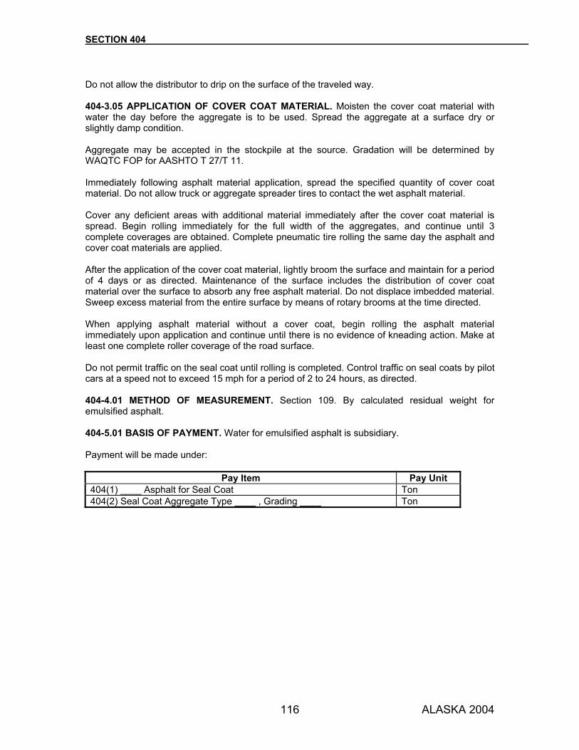
SECTION 404
ALASKA 2004 116
Do not allow the distributor to drip on the surface of the traveled way. 404-3.05 APPLICATION OF COVER COAT MATERIAL. Moisten the cover coat material with water the day before the aggregate is to be used. Spread the aggregate at a surface dry or slightly damp condition. Aggregate may be accepted in the stockpile at the source. Gradation will be determined by WAQTC FOP for AASHTO T 27/T 11. Immediately following asphalt material application, spread the specified quantity of cover coat material. Do not allow truck or aggregate spreader tires to contact the wet asphalt material. Cover any deficient areas with additional material immediately after the cover coat material is spread. Begin rolling immediately for the full width of the aggregates, and continue until 3 complete coverages are obtained. Complete pneumatic tire rolling the same day the asphalt and cover coat materials are applied. After the application of the cover coat material, lightly broom the surface and maintain for a period of 4 days or as directed. Maintenance of the surface includes the distribution of cover coat material over the surface to absorb any free asphalt material. Do not displace imbedded material. Sweep excess material from the entire surface by means of rotary brooms at the time directed. When applying asphalt material without a cover coat, begin rolling the asphalt material immediately upon application and continue until there is no evidence of kneading action. Make at least one complete roller coverage of the road surface. Do not permit traffic on the seal coat until rolling is completed. Control traffic on seal coats by pilot cars at a speed not to exceed 15 mph for a period of 2 to 24 hours, as directed. 404-4.01 METHOD OF MEASUREMENT. Section 109. By calculated residual weight for emulsified asphalt. 404-5.01 BASIS OF PAYMENT. Water for emulsified asphalt is subsidiary. Payment will be made under:
Pay Item Pay Unit 404(1) ____ Asphalt for Seal Coat Ton 404(2) Seal Coat Aggregate Type ____ , Grading ____ Ton

117 ALASKA 2004
SECTION 405
SURFACE TREATMENT
405-1.01 DESCRIPTION. Construct a single or multiple course asphalt surface treatment. 405-2.01 MATERIALS. Use materials that conform to the following:
Asphalt Section 702, for the type and grade specified Surface Treatment Aggregate Subsection 703-2.05, for the grading specified Blotter Material Suitable clean sand
CONSTRUCTION REQUIREMENTS 405-3.01 PRIME COAT. Apply prime coat, when specified, per Section 403, Prime Coat. Allow a curing period of up to 4 days between the application of the prime coat and the next application of asphalt material, as directed. Maintain the primed surface during the curing period. Repair all holes, ravels and areas deficient in prime with asphalt treated materials, by penetration methods, or other approved procedures. 405-3.02 SURFACE TREATMENT. Apply each course (asphalt and surface treatment aggregate per Section 404, Seal Coat. Allow each course to cure for a period of 4 days before applying additional courses. Surface treatment aggregate may be accepted in stockpile at the source. Gradation will be determined by WAQTC FOP for AASHTO T 27/T 11. 405-3.03 OPENING TO TRAFFIC. Keep the highway open to traffic at all times. As soon as the final layer is rolled, controlled traffic may be permitted as specified under Subsection 404-3.05. 405-4.01 METHOD OF MEASUREMENT. Section 109. By calculated residual weight for emulsified asphalt. 405-5.01 BASIS OF PAYMENT. Water for emulsified asphalt is subsidiary. Payment will be made under:
Pay Item Pay Unit 405(1) ______ Asphalt for Surface Treatment Ton 405(2) Aggregate for Surface Treatment, Grading ___ Ton
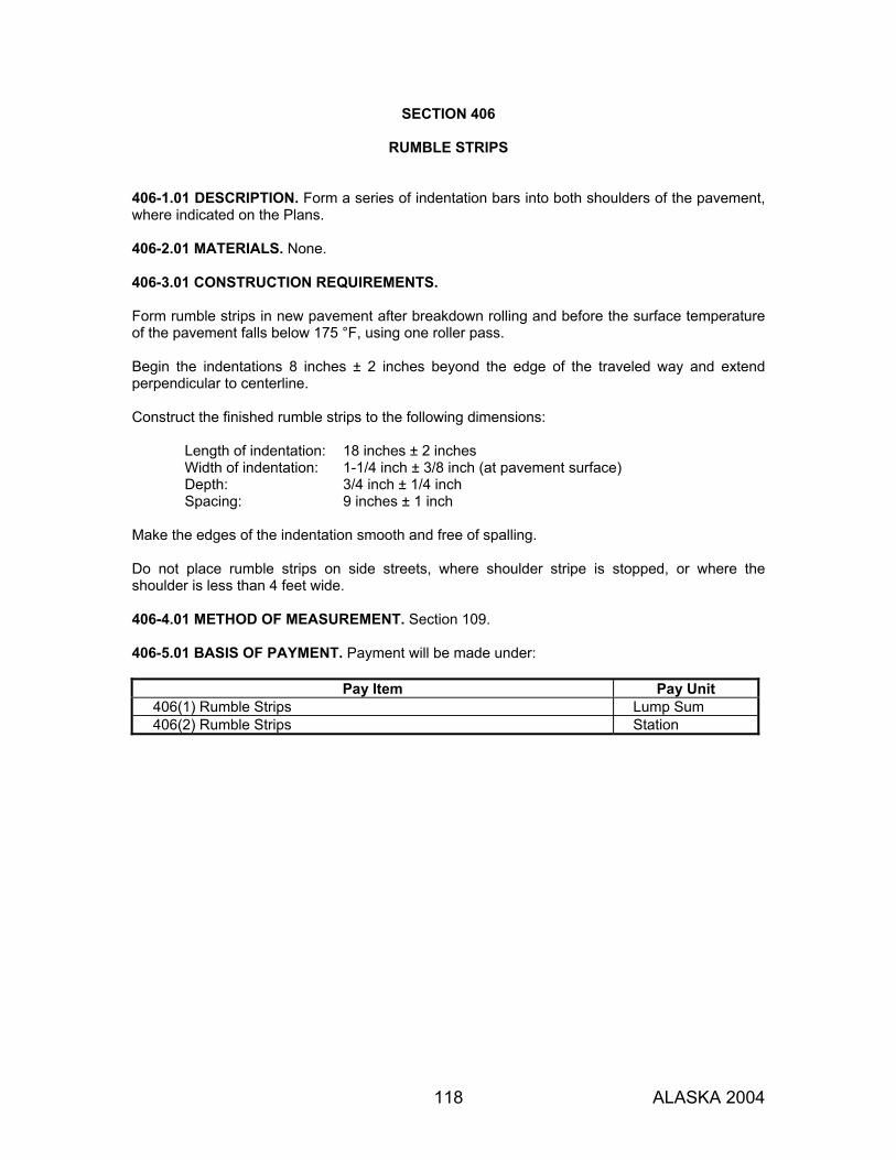
118 ALASKA 2004
SECTION 406
RUMBLE STRIPS
406-1.01 DESCRIPTION. Form a series of indentation bars into both shoulders of the pavement, where indicated on the Plans. 406-2.01 MATERIALS. None. 406-3.01 CONSTRUCTION REQUIREMENTS. Form rumble strips in new pavement after breakdown rolling and before the surface temperature of the pavement falls below 175 °F, using one roller pass. Begin the indentations 8 inches ± 2 inches beyond the edge of the traveled way and extend perpendicular to centerline. Construct the finished rumble strips to the following dimensions:
Length of indentation: 18 inches ± 2 inches Width of indentation: 1-1/4 inch ± 3/8 inch (at pavement surface) Depth: 3/4 inch ± 1/4 inch Spacing: 9 inches ± 1 inch
Make the edges of the indentation smooth and free of spalling. Do not place rumble strips on side streets, where shoulder stripe is stopped, or where the shoulder is less than 4 feet wide. 406-4.01 METHOD OF MEASUREMENT. Section 109. 406-5.01 BASIS OF PAYMENT. Payment will be made under:
Pay Item Pay Unit 406(1) Rumble Strips Lump Sum 406(2) Rumble Strips Station
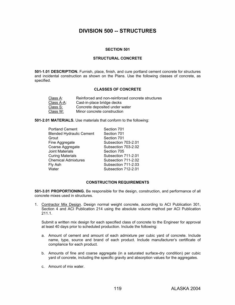
119 ALASKA 2004
DIVISION 500 -- STRUCTURES
SECTION 501
STRUCTURAL CONCRETE 501-1.01 DESCRIPTION. Furnish, place, finish, and cure portland cement concrete for structures and incidental construction as shown on the Plans. Use the following classes of concrete, as specified.
CLASSES OF CONCRETE
Class A: Reinforced and non-reinforced concrete structures Class A-A: Cast-in-place bridge decks Class S: Concrete deposited under water Class W: Minor concrete construction
501-2.01 MATERIALS. Use materials that conform to the following:
Portland Cement Section 701 Blended Hydraulic Cement Section 701 Grout Section 701 Fine Aggregate Subsection 703-2.01 Coarse Aggregate Subsection 703-2.02 Joint Materials Section 705 Curing Materials Subsection 711-2.01 Chemical Admixtures Subsection 711-2.02 Fly Ash Subsection 711-2.03 Water Subsection 712-2.01
CONSTRUCTION REQUIREMENTS 501-3.01 PROPORTIONING. Be responsible for the design, construction, and performance of all concrete mixes used in structures. 1. Contractor Mix Design. Design normal weight concrete, according to ACI Publication 301,
Section 4 and ACI Publication 214 using the absolute volume method per ACI Publication 211.1. Submit a written mix design for each specified class of concrete to the Engineer for approval at least 40 days prior to scheduled production. Include the following: a. Amount of cement and amount of each admixture per cubic yard of concrete. Include
name, type, source and brand of each product. Include manufacturer’s certificate of compliance for each product.
b. Amounts of fine and coarse aggregate (in a saturated surface-dry condition) per cubic
yard of concrete, including the specific gravity and absorption values for the aggregates.
c. Amount of mix water.
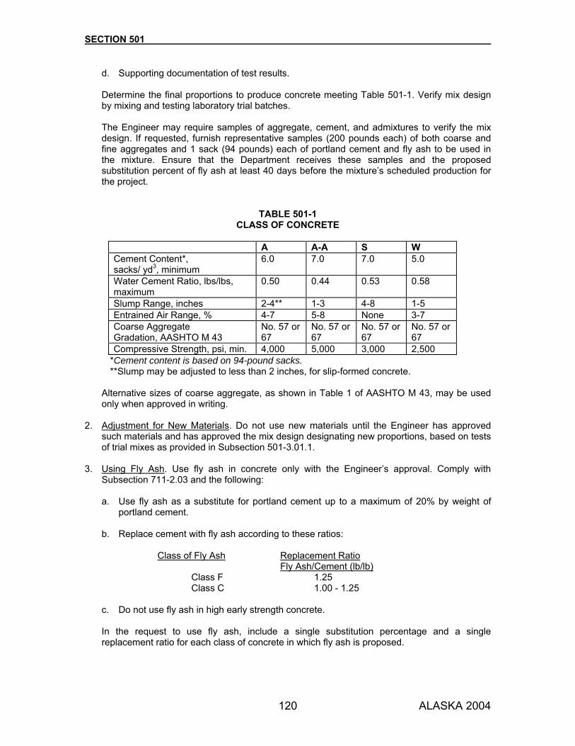
SECTION 501
ALASKA 2004 120
d. Supporting documentation of test results.
Determine the final proportions to produce concrete meeting Table 501-1. Verify mix design by mixing and testing laboratory trial batches. The Engineer may require samples of aggregate, cement, and admixtures to verify the mix design. If requested, furnish representative samples (200 pounds each) of both coarse and fine aggregates and 1 sack (94 pounds) each of portland cement and fly ash to be used in the mixture. Ensure that the Department receives these samples and the proposed substitution percent of fly ash at least 40 days before the mixture’s scheduled production for the project.
TABLE 501-1 CLASS OF CONCRETE
A A-A S W Cement Content*, sacks/ yd3, minimum
6.0 7.0 7.0 5.0
Water Cement Ratio, lbs/lbs, maximum
0.50 0.44 0.53 0.58
Slump Range, inches 2-4** 1-3 4-8 1-5 Entrained Air Range, % 4-7 5-8 None 3-7 Coarse Aggregate Gradation, AASHTO M 43
No. 57 or 67
No. 57 or 67
No. 57 or 67
No. 57 or 67
Compressive Strength, psi, min. 4,000 5,000 3,000 2,500 *Cement content is based on 94-pound sacks. **Slump may be adjusted to less than 2 inches, for slip-formed concrete.
Alternative sizes of coarse aggregate, as shown in Table 1 of AASHTO M 43, may be used only when approved in writing.
2. Adjustment for New Materials. Do not use new materials until the Engineer has approved
such materials and has approved the mix design designating new proportions, based on tests of trial mixes as provided in Subsection 501-3.01.1.
3. Using Fly Ash. Use fly ash in concrete only with the Engineer’s approval. Comply with
Subsection 711-2.03 and the following:
a. Use fly ash as a substitute for portland cement up to a maximum of 20% by weight of portland cement.
b. Replace cement with fly ash according to these ratios:
Class of Fly Ash Replacement Ratio
Fly Ash/Cement (lb/lb) Class F 1.25 Class C 1.00 - 1.25
c. Do not use fly ash in high early strength concrete.
In the request to use fly ash, include a single substitution percentage and a single replacement ratio for each class of concrete in which fly ash is proposed.
SECTION 501
ALASKA 2004 121
As an alternative to using fly ash and cement as separate components, you may use a blended hydraulic cement meeting Subsection 701-2.02.
4. Using Admixtures. Include test results demonstrating that the admixture conforms to these
Specifications.
When using two or more admixtures in the same mix from different manufacturers, provide manufacturer’s certifications showing that they are compatible.
5. Approval. Obtain the Engineer’s approval of all mix designs, prior to use. 501-3.02 ACCEPTANCE OF CONCRETE. 1. General. The Engineer may accept Class W concrete and minor quantities of other classes of
concrete based on Certificates of Compliance provided by the supplier as described in Section 501-3.02.2.
The Engineer will accept all other concrete based on conformance to the requirements for temperature, slump, air content, water cement ratio, and the specified 28-day strength for sublots as tested and determined by the Department. A sublot is defined as the material represented by an individual strength test. An individual strength test is the average strength of cylinders from the same sample of material. Each sublot will meet the specified strength requirement when both of the following conditions are met: a. Individual strength tests do not fall below the specified strength by more than 12.5% or
500 psi, whichever is least. b. An individual strength test averaged with the two proceeding individual strength tests
meets or exceeds specified strength (for the same class of concrete on the same contract).
2. Certification of Compliance. Provide a Certificate of Compliance for each truckload of
concrete. Certify that the delivered concrete is in compliance with the mix design and include the following information:
a. Manufacturer plant (batching facility) b. Department contract number c. Date d. Time batched e. Truck No. f. Initial revolution counter reading g. Quantity (quantity batched this load) h. Type of concrete by class and producer design mix number i. Cement producer, type, and manufacturer’s mill test report number j. Fly ash (if used) brand and Type k. Approved aggregate gradation designation l. Mix design weight per cubic yard and actual batched weights for:
(1) Cement (2) Fly ash (if used) (3) Coarse concrete aggregate and moisture content (each size) (4) Fine concrete aggregate and moisture content (5) Water (including free moisture in aggregates) (6) Admixtures brand and total quantity batched

SECTION 501
ALASKA 2004 122
(7) Air-entraining admixture (8) Water reducing admixture (9) Other admixture
The Certificate of Compliance must be signed by a responsible representative of the concrete producer, affirming the accuracy of the information provided.
3. Conformance to Mix Design. Produce a concrete mix which conforms to the approved mix
design, within the following tolerances:
a. Coarse Aggregate weights ±2% b. Fine Aggregate weights ±2% c. Fine Aggregate Fineness Modulus ±0.2 d. Cementitious Material weight ±1%
If the total cementitious material weight is made up of different components, keep the component weights within the following tolerances:
(1) Portland cement ±1% (2) Fly ash ±5% (3) Microsilica ±10%
4. Test Methods. Acceptance testing will be performed by the Department according to the
following test methods:
WAQTC TM 2 Sampling Freshly Mixed Concrete WAQTC FOP for AASHTO T 309 Temperature of Freshly Mixed Portland Cement Concrete AASHTO T 22 Compressive Strength of Cylindrical Concrete Specimens WAQTC FOP for AASHTO T 27/T 11 Sieve Analysis of Fine and Coarse Aggregates, and
Materials Finer Than No. 200 Sieve in Mineral Aggregate by Washing
WAQTC FOP for AASHTO T 23 Making and Curing Concrete Test Specimens in the Field WAQTC FOP for AASHTO T 119 Slump of Hydraulic Cement Concrete WAQTC FOP for AASHTO T 121 Mass per Cubic Foot, Yield, and Air Content of Concrete WAQTC FOP for AASHTO T 152 Air Content of Freshly Mixed Concrete by the Pressure
Method AASHTO T 231 Capping Cylindrical Concrete Specimens
5. Point of Acceptance. The Engineer will determine aggregate gradation for acceptance based
on random samples taken at the plant.
The Engineer will determine concrete strength, slump, temperature, and entrained air (if applicable) for acceptance based on samples taken at the discharge point of the placement system, except that Class S concrete will be sampled at the truck discharge. Provide adequate and representative samples of the fresh concrete as directed at locations designated by the Engineer for the testing of concrete properties and making of strength specimens.

SECTION 501
ALASKA 2004 123
Concrete with compressive strengths (fc) which fails to meet specified acceptance level requirements will be evaluated for structural adequacy. If the material is found to be adequate, payment will be adjusted according to Subsection 501-5.01.
6. Water/Cement Ratio Conformance. The Engineer will determine the actual water cement
ratio from the certified proportions of the mix. For slip-formed concrete, do not exceed the maximum water cement ratio in the mix design or the slump limits under 501-3.01.1.
7. Rejecting Concrete. The Engineer may reject any batch or load of concrete that fails to meet
the minimum specified acceptance levels for temperature, slump, or air content. The Engineer may reject any batch or load of concrete, prior to sampling, that appears defective in composition. Do not incorporate rejected material into the structure. The Engineer may reject any structure or portion of a structure containing concrete which fails to meet specified acceptance level for strength, failed to maintain the required curing conditions, or is cracked, spalled, or otherwise defective.
501-3.03 BATCHING. Except as provided in this specification, use a central batching plant to handle, measure, and batch the materials. 1. Portland Cement. Use either sacked or bulk cement. Do not use a fraction of a sack of
cement in a batch of concrete unless the cement is weighed.
Weigh bulk cement on a certified weighing device. Ensure that the bulk cement weighing hopper is properly sealed and vented to prevent dusting during operation. Do not suspend the discharge chute from the weighing hopper. Arrange the chute so that cement will not lodge in it or leak from it. Interlock the bulk cement hopper’s discharge mechanism against: a. opening before the full batch is in the hopper and while the hopper is being filled, b. closing before the hopper contents are entirely discharged and the scales are back in
balance, and c. opening if the batch in the hopper is either over or under weight by more than 1% of the
amount specified.
2. Water. Measure water either by volume or by weight. Unless the water is to be weighed, include with the water-measuring equipment an auxiliary tank that will fill the measuring tank. Use a measuring tank equipped with an outside tap and valve to help in checking the setting, unless another means can readily and accurately determine the amount of water in the tank.
3. Aggregates. When building up stockpiles, prevent segregation. Do not stockpile aggregates
from different sources and of different gradings together.
When transporting aggregates from stockpiles or other sources to the batching plant, maintain a uniform grading of the material. Do not use aggregates that have become segregated or mixed with earth or foreign material. If aggregates have been produced or handled by hydraulic methods, or if they have been washed, stockpile them or bin them for draining at least 12 hours before they are batched. Rail shipment requiring more than 12 hours is adequate as binning if the car bodies drain freely. If the aggregates contain high or non-uniform moisture content, storage or stockpile periods may require more than 12 hours. Do not use binned aggregates that contain ice, are frozen, or have been heated directly by gas or oil flame or on sheet metal over an open fire. When heating aggregates in bins, use steam-coil or water-coil heating. Use other methods only when approved. If using live steam to thaw frozen aggregate piles, completely drain excess moisture.

SECTION 501
ALASKA 2004 124
4. Bins and Scales. Include at the batching plant adequate bins for each required size of aggregate. Use bins that are designed to discharge freely into the weighing hoppers. Provide control so that as the material in the weighing hopper(s) approaches the desired quantity, the bin adds material slowly and shuts off with precision. Provide a means of removing any overload.
Use hoppers constructed to eliminate accumulations of tare materials and to fully discharge without jarring the scales. Include partitions between bins and hoppers to prevent spilling. Maintain batching plant structures at the level of accuracy required by the design of the weighing mechanism. Provide devices at the bins or at the concrete mixer for weighing or measuring air-entraining admixtures or other additives. Weigh aggregates and cement with a scale that is accurate within a tolerance of 0.5% and is certified annually. If using the beam type scales, provide a “tell-tale” dial to indicate to the operator that the required load in the weighing hopper is being approached. The device must indicate at least the last 200 pounds of load. Use poises designed to lock in any position and to prevent unauthorized removal. Ensure that while charging the hopper, the operator can see the weigh beam and “tell-tale” device and can easily access the controls. Provide enough clearance between the scale parts, hoppers, and bin structures to avoid displacing the parts or causing friction between the parts. Use pivot mountings designed to maintain the spacing of knife edges under all circumstances. Keep scales clean. Furnish ten 50-pound weights for checking.
5. Batching. When hauling batches to the mixer, transport bulk cement either in waterproof compartments or place it between the fine and coarse aggregates. Sacked cement may be transported on top of the aggregates.
Deliver batches to the mixer separate and intact. Dump each batch into the mixer without loss. When carrying more than one batch on the truck, avoid spilling material from one batch compartment into another while dumping. When placing a small volume of concrete, or when determining that proportioning by batching equipment is otherwise impractical, you may, with written approval, proportion the materials by weighing them on platform scales or by loose volume. Measure the quantities separately using equipment that will ensure uniform proportioning. Wheelbarrows or bottomless boxes, with carefully predetermined volumes, or other appropriate methods may be used. Do not proportion using shovels. When determining the volumes of the aggregates, consider the bulking effect of any moisture contained in the materials. Immediately before using liquid air entraining agents, stir and agitate them until they are mixed. Add the air entraining agent to the mix simultaneously with the water. However, when mixing with water heated above 80 °F, add the air entraining agent after the aggregate and water are mixed. Ensure that computerized batch plants do not include materials in a transit mixer from a previous load that was not completely used.
501-3.04 MIXING. Mix concrete at the construction site, at a central mixing plant, in a truck mixer, or by a combination of central plant and truck mixing. Conform to AASHTO M 157 and the following:
SECTION 501
ALASKA 2004 125
1. Mixing at Concrete Construction Site. Mix concrete in a batch mixer of the approved type and
capacity. Mix for at least 60 seconds after all component materials, including water, are in the drum.
Begin charging water into the mixer before the cement and aggregates enter the drum. During mixing, operate the drum at speeds specified by the manufacturer and shown on the name plate on the machine. Replace pickup blades in the drum of the mixer that, at any point, are worn down 3/4 inch or more. Discharge the entire contents of the mixer from the drum before placing materials for a succeeding batch into the drum. Use a mixer equipped with a mechanism that prevents aggregates from being added after mixing has begun. Use a mixer equipped with a timing device to mix for the minimum time specified. Do not allow the batch volume to exceed the manufacturer's rated capacity of the mixer. Do not use a mixer with a rated capacity of less than 1 cubic yard without written permission. Mix only the quantity of concrete required for immediate use. Do not retemper concrete. When stopping mixing for a considerable length of time, clean the mixer thoroughly. When resuming mixing, include with the first batch of concrete material placed in the mixer enough sand, cement, and water to coat the inside surface of the drum without diminishing the required cement content of the mix.
2. Central Plant Mixing. When mixing concrete at a central plant, use a mixer and methods
according to the requirements of Subsection 501-3.04.1.
Transport mixed concrete from the central mixing plant to the work site in agitator trucks of the approved design. Regulate concrete delivery to place concrete at a continuous rate. Keep the intervals between batch deliveries short enough to prevent the concrete in place from hardening partially. Do not allow the intervals to exceed 30 minutes. Use an agitator truck equipped with a closed, watertight, revolving drum that is suitably mounted and capable of transporting and discharging the concrete without segregation. Ensure that the drum agitating speed is at least 2 but not more than 6 revolutions per minute. Do not allow the volume of mixed concrete permitted in the drum to exceed the manufacturer's rating nor exceed 80% of the gross volume of the drum. With approval, you may use open-top revolving-blade truck mixers instead of agitator trucks to transport central plant mixed concrete. Furnish the mixer manufacturer’s data showing the gross volume of agitator bodies, expressed in cubic feet. Deliver the concrete to the work site and discharge it from the truck completely. Place the concrete in the forms ready for vibration within 1.5 hours after introducing the cement to the aggregates. If the Engineer approves, you may extend the above period 2 minutes for every degree of temperature the concrete is below 70 °F at the time it is ready for placement, to a maximum of 2 hours. In hot weather, or under conditions that cause the concrete to set quickly, the Engineer may require discharge of the concrete in less than 1.5 hours. Discharge concrete with a uniform consistency. Do not exceed a difference of 1 inch between slumps of samples from the 1/4 and 3/4 points of the discharged load.

SECTION 501
ALASKA 2004 126
All concrete, regardless of agitation time, must conform to the limitations of Table 501-1. Agitate the concrete mixture continuously until it is discharged from the truck.
3. Truck Mixing. Concrete may be mixed in a truck mixer. Use truck mixing according to the following provisions:
Use a truck mixer with either a closed, watertight, revolving drum or an open-top, revolving-blade or paddle that combines all ingredients into a thoroughly mixed and uniform mass and discharges concrete with a uniform consistency. Do not exceed a difference of 1 inch between slumps of samples from the 1/4 and 3/4 points of the discharged load. Mixing speed for the revolving-drum type mixer must be at least 4 revolutions per minute but do not exceed a peripheral velocity of the drum of 225 feet per minute. For the open-top type mixer, mixing speed must be between 4 and 16 revolutions per minute of the mixing blades or paddles. Agitation speed for both the revolving-drum and the revolving-blade type mixers must be between 2 and 6 revolutions per minute of the drum or mixing blades or paddles. Comply with the truck mixer manufacturer's rated capacity, but do not exceed the limitations in this specification. Normal rated capacities, expressed as percentages of the gross volume of the drum or container, must not exceed 57.5% for truck mixing and 80% for agitating. When truck mixing, a volume of concrete 10% greater than the normal rated capacity of 57.5% of the volume of the drum or container (that is, 63.25%) is acceptable provided the manufacturer guarantees that the increased volume will be adequately mixed and if you do additional mixing as stated in this specification. The manufacturer must attach to each truck mixer a metal plate that states the capacity of volume of mixed concrete as a mixer and as an agitator. When the manufacturer's ratings of capacity are less than the limits indicated above, use the manufacturer's ratings. Designate the mixing amount in number of revolutions. When mixing the concrete in a truck mixer loaded to its normal rated capacity, ensure that the drum or blades at mixing speed make at least 50 but no more than 100 revolutions after all materials, including mixing water, have been charged into the drum. If the batch is greater than normal rated capacity, but not more than 10% greater, ensure that the drum or blades at mixing speed make at least 70 but no more than 100 revolutions. All revolutions after 100 must be at agitating speed. Provide a counter that will indicate the number of revolutions of the drum or blades. Also, provide a locking device to prevent the mixer from discharging before the required number of drum revolutions are completed. Deliver the concrete to the work site and discharge it from the truck completely. Place the concrete in the forms ready for vibration within 1.5 hours after introducing the cement to the aggregates. With approval, you may extend the above period 2 minutes for every degree of temperature at which the concrete is delivered below 70 °F, to a maximum total time of 2 hours. In hot weather, or under conditions that cause the concrete to set quickly, the Engineer may require discharge of the concrete in less than 1.5 hours. All concrete regardless of agitation time must conform to the limitations in Table 501-1. Agitate the concrete mixture continuously until it is discharged from the truck.

SECTION 501
ALASKA 2004 127
Regulate concrete delivery to place concrete at a continuous rate. Keep the intervals between batch deliveries short enough to prevent the concrete in place from hardening partially. Do not allow the interval to exceed 30 minutes. When mixing the concrete in a truck mixer, begin mixing within 30 seconds after the cement has been intermingled with the aggregates. Except when using truck mixers exclusively as agitators, provide the mixers with a water-measuring device to accurately measure the water for each batch. Mount the device on the truck mixer or at the truck mixer loading point. Make the tank readily accessible to determine the amount of water delivered. The delivered amount of water must be within a tolerance of 1% of the indicated amount when the tank, if mounted on the truck mixer, is stationary and practically level. When using wash water (flush water) as a portion of the mixing water for the succeeding batch, accurately measure it and use it when determining the amount of additional mixing water required. With approval, you may use a properly calibrated combination materials transporter/mobile concrete mixing plant in good condition. Approval will be based on its ability to consistently produce specification concrete conforming with the manufacturer's published criteria. Furnish manufacturer's handbooks for the mixing plant proposed.
4. Hand Mixing. Use hand mixing only with written permission. When permitted, perform hand mixing only on watertight platforms. Measure the proper amount of coarse aggregate in a measuring box and spread it on the platform. Spread the fine aggregate on the coarse aggregate layer, with the two layers no more than 12 inches in total depth. Spread on this mixture the dry cement and then turn the whole mass at least two times dry. Add enough clean water, evenly distribute it, and turn the entire mass at least six times or until all coarse aggregate particles are covered thoroughly with mortar and the mixture is uniform in color and appearance. Hand-mixed batches must not exceed 0.5 cubic yard in volume. Do not hand-mix concrete that will be placed under water.
501-3.05 COLD WEATHER CONCRETE. Submit a written cold weather concreting plan when air temperatures are expected to fall below 35 °F during the cure period. Obtain the Engineer’s approval of the plan and put it into effect before placing any concrete when the descending air temperature in the shade, away from artificial heat, falls below 40 °F or, in the opinion of the Engineer, will likely do so within 24 hours after concrete is placed. Have in place the materials and equipment required to heat mixing water and aggregate and to protect freshly placed concrete from freezing. 1. Temperature of Concrete. When the air temperature falls below 40 °F, ensure that concrete
placed in forms has a temperature between 50 °F and 70°F. Obtain these temperatures by heating the mixing water and/or aggregate. Heat mixing water to no more than 160 °F. Heat aggregate as provided in Subsection 501-3.03.
When the temperature of the water or aggregate exceeds 100 °F, mix them together so that the temperature of the mix does not exceed 80 °F when the cement is added.
2. Admixtures. Use only admixtures shown in the approved mix design. Do not use calcium
chloride. 3. Cold Weather Placement. When placing concrete in cold weather, follow these precautions in
addition to the above requirements:

SECTION 501
ALASKA 2004 128
a. Heat forms and reinforcing steel before placing concrete to remove frost, ice, and snow from surfaces that will contact fresh concrete.
b. When fresh concrete will contact hardened concrete, warm the surface of the hardened
concrete to at least 35 °F and thoroughly wet. Remove free water before placing fresh concrete.
4. Protection of Concrete. When using Type I or II cement, maintain freshly placed concrete at a temperature of at least 70 °F for 3 days or at least 50 °F for 5 days. When using Type III cement, maintain concrete at a temperature of at least 70 °F for 2 days or at least 50 °F for 3 days. The above requirements do not apply when the concrete no longer is in danger of freezing or when air temperatures of 40 °F or higher are anticipated during the 2 weeks after concrete placement. Maintain the concrete temperature using methods such as insulated forms, enclosures, and indirect heat. Maintain curing moisture. Protect the structure from overheating and fire. At the end of the curing period, remove the protection so the concrete drops in temperature gradually and not more than 30 °F in the first 24 hours. When placing concrete within cofferdams and curing it by flooding with water, the above conditions do not apply if the water that contacts the concrete is not allowed to freeze. Wait to dewater until the Engineer determines that the concrete has cured enough to withstand freezing temperatures and hydrostatic pressure. Protect the concrete during cold weather operations. Remove and replace concrete injured by frost action or overheating at no cost to the Department.
501-3.06 HOT WEATHER CONCRETE. Provide concrete within the specified temperature limits as follows: 1. Shade or cool aggregate piles. Do not sprinkle fine aggregate piles with water. If sprinkling
coarse aggregates, monitor the moisture content and adjust the mixing water for the free water in the aggregate.
2. Refrigerate mixing water or replace all or part of the mixing water with crushed ice, provided
the ice is completely melted by concrete placing time. If the concrete temperature would probably exceed 90 °F using normal methods, take temperature-reduction measures as required by the Engineer before placing the concrete. If the air temperature exceeds 90 °F when placing concrete, use water spray or other methods to cool concrete-contact surfaces to less than 90 °F. These surfaces include forms, reinforcing steel, steel beam flanges, and others that touch the mix. Reduce the time between mixing and placing and do not permit mixer trucks to remain in the sun while waiting to discharge concrete. Shade chutes, conveyors, and pump lines. Finish the concrete without delay. Provide water-fogging equipment at the site if needed after finishing to prevent plastic cracks.
When placing deck concrete that is 80 °F or hotter, install equipment at the site to show relative humidity and wind velocity. If the evaporation rate at the concrete site is 0.2 lb/ft2/h or more (determined from Table 501-2), surround the fresh concrete with an enclosure. This enclosure will protect the concrete from wind blowing across its surface until the curing compound is applied.
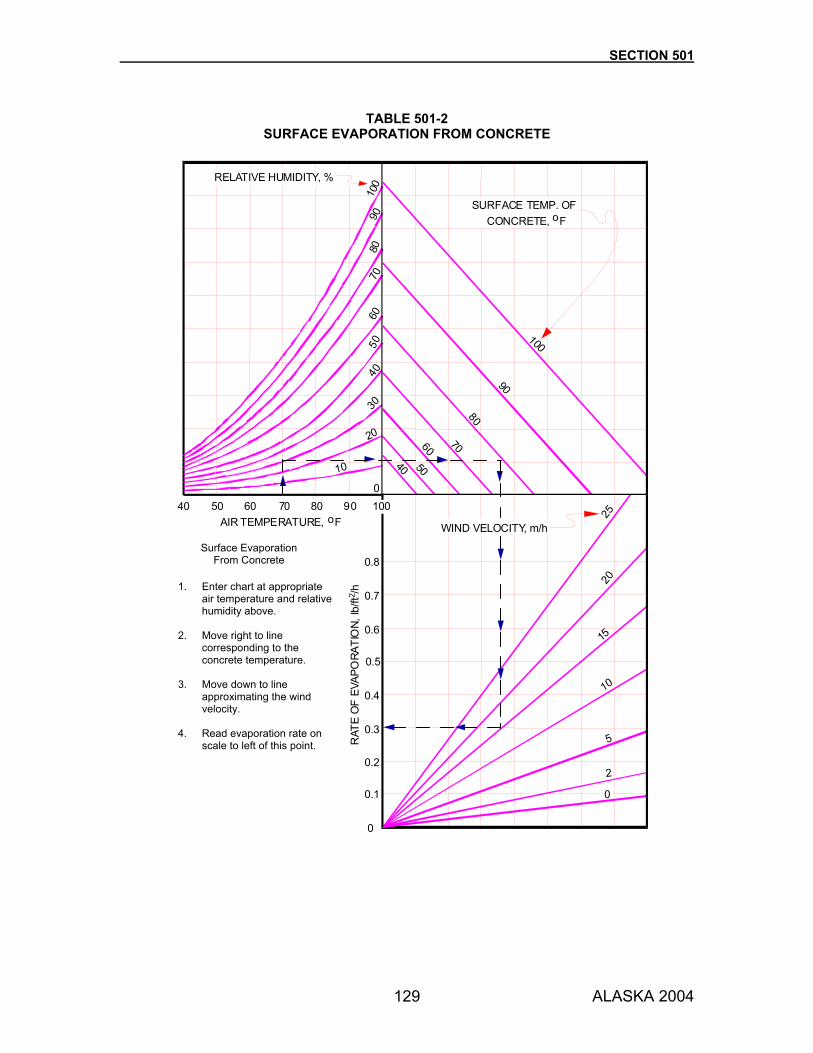
SECTION 501
ALASKA 2004 129
100
90
80
70605040
9010
080
7060
5040
30
20
10
040 50 60 70 80 90 100
2520
15
10
5
2
0
0
0.1
0.2
0.3
0.4
0.5
0.6
0.7
0.8
AIR TEMPERATURE, oF
RAT
EO
FEV
APO
RATI
ON,
lb/ft
2 /h
SURFACE TEMP. OFCONCRETE, oF
RELATIVE HUMIDITY, %
WIND VELOCITY, m/h
TABLE 501-2
SURFACE EVAPORATION FROM CONCRETE
Surface Evaporation From Concrete
1. Enter chart at appropriate air temperature and relative humidity above.
2. Move right to line
corresponding to the concrete temperature.
3. Move down to line
approximating the wind velocity.
4. Read evaporation rate on
scale to left of this point.
SECTION 501
ALASKA 2004 130
501-3.07 FORMS. Use forms and falsework designed and constructed according to Section 512. Do not use permanent metal forms for bridge deck construction. 501-3.08 PLACING CONCRETE. 1. General. Provide a placement plan. Place and consolidate the concrete mix in approved
forms to make a dense homogeneous concrete. Place concrete before it has initially set or within 30 minutes after mixing, except as permitted in Subsection 501-3.04. Place concrete continuously and compact each layer before the succeeding one is dumped to prevent unplanned cold joints or damage to newly set concrete.
Place concrete as near as possible to final position. Do not deposit a large quantity at any point and run or work it along the forms. Regulate concrete placement so that the pressures caused by wet concrete do not exceed those used in the design of the forms. Avoid segregating coarse or fine portions of the mixture while placing concrete. Limit lift thickness to no more than 2 feet, or the capacity of the vibrators to consolidate and merge the concrete with the previous lift. Use a tube with a hopper head or other approved device when dropping concrete more than 5 feet. Use clean, watertight equipment and material, but do not use those made of aluminum. Equip chutes on steep slopes with baffles or reverses.
Eliminate rock pockets and air bubbles. Vibrate along faces to obtain smooth surfaces. Prevent mortar from spattering on forms and reinforcing steel and from drying ahead of the final concrete covering.
Use troughs, pipes, or short chutes as aids in placing concrete. Where steep slopes are required, use troughs and chutes equipped with baffle boards or short enough to reverse the direction of movement. Keep chutes, troughs, and pipe clean and free of hardened concrete by flushing thoroughly with water after each run. Keep discharge water used for flushing clear of the concrete in place. When discharge must be intermittent, provide a hopper or other device for regulating the discharge. Consolidate all concrete, except underwater or other exempted placements, by mechanical vibration. Use internal vibration, except for thin sections, with forms designed for external vibration. Use proper sized vibrators with a minimum frequency of 5,000 cycles per minute and capable of visibly affecting a properly designed mixture with a 1-inch slump for a distance of at least 18 inches from the vibrator. Use enough vibrators to consolidate the fresh concrete within 15 minutes of placing it in the forms, with one or more spare vibrators in case of breakdown. Vibrate at point of deposit. Insert vibrators vertically and withdraw slowly to avoid segregation or grout pockets. Vibrate in a uniform pattern spaced less than 1.5 times the radius of visible effectiveness. Avoid vibration of hardened layers below the placement. Do not hold vibrators against forms or reinforcing steel or use them to flow the concrete or spread it into place. Manipulate vibrators to produce concrete that is free of voids and that has the proper texture on exposed faces and the maximum consolidation. Do not hold vibrators so long that the concrete segregates or laitance forms on the surface. Place concrete continuously throughout each section of the structure or between indicated joints. If an emergency forces you to stop placing concrete before a section is completed, place bulkheads as the Engineer may direct. Treat the resulting joint as a construction joint. Place and vibrate concrete in piles as specified in Subsection 505-3.06. Place concrete in the superstructure only after substructure forms are removed to allow inspection of supporting concrete.

SECTION 501
ALASKA 2004 131
Place concrete in precast member in a sequence to obtain a well-consolidated concrete and to prevent settlement or shrinkage cracks. Place the concrete in arch rings to load the centering uniformly and symmetrically. Place transverse arch sections so that each section is cast in one continuous operation. Bond each section together with suitable keys or dowels. Obtain approval for the sequence of placement and arrangement of sections. Structures with excessive honeycomb areas will be rejected. Upon written notice that a structure has been rejected, remove and rebuild the structure, in part or wholly as specified.
2. Concrete Decks. Hold a preconcreting conference at least 5 working days before placing concrete in decks. Discuss construction procedures, personnel, and equipment to be used. Include your superintendent and all foremen in charge of placing steel reinforcing bars, placing the concrete, and finishing it.
If the project includes more than one slab, and if your key personnel change between concreting operations, hold an additional conference to include replacement personnel before placing the next slab. Before placing concrete decks, obtain the Engineer’s approval of the concrete production and placement rates, screed operator, concrete foreman, and concrete finishers. Ensure that adequate finishing tools and equipment are at the site. Before placing any concrete, operate the finishing machine over the entire length of the slab to check screed deflection, reinforcing steel clearance, and concrete thickness. Begin placing concrete only after the Engineer approves this test. Check (and adjust if necessary) falsework and wedges to minimize settlement and deflection from the added weight of the concrete slab. Also, install devices, such as telltales, to enable the Engineer to readily measure settlement and deflection. Schedule the concrete placement to finish it during daylight. To finish after dark, obtain the Engineer’s approval and provide adequate lighting. The placement operation must cover the full width of the roadway and the full width between construction joints. Begin placing the concrete at the low end and proceed uphill. Do not place concrete for the deck surface more than 10 feet ahead of the strike off. Limit the rate of placing concrete to what can be finished before the beginning of the initial set. During precipitation, or when the Engineer determines that precipitation is likely before the finishing is completed, do not place concrete in decks or other sections requiring finishing on the top surface, unless the materials and equipment needed to protect the concrete and complete the finishing operations are readily available.
3. Pumping Concrete. You may place concrete by pumping if you demonstrate that the equipment will handle the class of concrete, with the slump and air content specified, and that no equipment vibrations will damage freshly placed concrete. Use a pump that produces a continuous stream of concrete without air pockets. When pumping is completed, the concrete remaining in the pipeline, if it will be used, must eject without contaminating the concrete or separating the ingredients. Discard concrete contaminated by priming or cleaning the pump. Take concrete samples for testing at the discharge end of the pipe. Provide the necessary samples of concrete as directed.
SECTION 501
ALASKA 2004 132
4. Vertical Members. Place concrete in columns, walls, substructures, and other similar vertical members in one continuous operation. Allow the concrete to set at least 12 hours before placing integral caps, slabs, or footings. Allow members to reach at least 80% of the ultimate strength (f 'c) shown on the Plans and have at least 7 days cure time before loading from horizontal members is applied.
5. Concrete Slab and Girder Spans. Cast slabs and girders with spans of 30 feet or less in one
continuous operation.
If casting girders spanning more than 30 feet in 2 operations, cast the girder stems to the bottom of the slab haunches, during the first operation. Provide approved shear keys at least 1-1/2 inches deep in the fresh concrete at the top of each girder stem. Provide enough keys to cover uniformly about one-half of the top surface of the girder stem. Remove the blocks as soon as the concrete has set enough to retain their shape. Wait at least 24 hours between the girder casting and the slab casting. Immediately before the slab casting, check falsework for shrinkage and settlement and tighten wedges to ensure minimum deflection of the stems from the added weight of the slab.
6. Deck Slabs on Steel Spans. Place the concrete deck slab on simple steel girder spans in not
more than 3 sections with the first section centered on the span.
On truss spans or continuous girder bridges, place the concrete deck slab as shown on the Plans or as directed. Subject to approval, you may deviate from the deck placing sequence shown on the Plans by casting the bridge deck continuously from one end to the other provided that you:
a. Do not use Type III cement for a continuous deck placement operation. b. Submit for approval a written proposal of the methods and means, equipment,
workers, and time schedule for conducting a continuous deck placement and finishing operation.
c. Stockpile the materials necessary to complete the placement and have the
equipment, incidentals, and workers on the site before beginning a continuous deck placement operation.
d. Ensure that the continuous deck placement and finishing operation proceeds at a
minimum rate of 30 feet per hour, measured longitudinally along the axis of the bridge.
Begin the continuous deck placement operation at the low end of the bridge and proceed uphill. If the Engineer approved the proposal for a continuous deck placement operation, the Department will observe and evaluate performance to the first planned construction joint in the sequence. At this point, the Engineer may authorize you to proceed with the continuous deck placement operation or suspend the placement and install a bulkhead. The Engineer's decision will be based on whether you can produce, deliver, and finish the deck concrete according to the Specifications and at a continuous rate that will permit the structure to accommodate final dead load deflections while the concrete is plastic. If the Engineer suspends the continuous deck placement operations after the first sequential pour placement, submit significant modifications for improving the continuous deck placement operations, beginning again at the other end of the bridge. Demonstrate this revised method as specified above for the initial placement.

SECTION 501
ALASKA 2004 133
If the Engineer suspends the continuous deck placement operation after the second attempt, abandon the method and follow the deck placing sequence shown on the Plans.
7. Underwater Placement. Only concrete used in cofferdams to seal out water may be placed
under water, unless otherwise specified or approved. Deposit concrete under water, using a tremie or pump. Carefully place the concrete in a compact mass and do not disturb it. Maintain still water at the point of deposit. Vent cofferdams during placement and curing to equalize hydrostatic pressure and prevent flow of water through the concrete during this period. Use watertight tremie tubes at least 10 inches in diameter and with a hopper at the top. When dumping a batch into the hopper, induce the flow of concrete by slightly raising the discharge end while keeping it in the deposited concrete. Use tremie tubes or pump discharge tubes equipped with a device that will prevent water from entering the tube while it is being charged with concrete. Support these tubes to permit the discharge end to move freely over the entire top surface of the work and to permit rapid lowering, when necessary, to retard or stop the flow of concrete. Fill the tubes using a method that will prevent washing the concrete. Completely submerge the discharge end in concrete at all times and ensure that the tube contains enough concrete to prevent water entry. Keep the flow continuous until the work is completed. Produce a concrete seal that is monolithic and homogeneous. The thickness of the seal will depend upon the hydrostatic head, bond and spacing of piles, size of cofferdam, and other related factors. However, the seal must be at least 2 feet thick. Before dewatering, allow the concrete in the seal to cure for at least 5 days after placing, or until the seal concrete achieves a minimum compressive strength of 2500 psi based on test cylinders cured under the same conditions, whichever occurs first. If placing a seal that must withstand hydrostatic pressure in water with a temperature below 45 °F, increase the curing time before dewatering as directed. Do not consider as curing time the time when the temperature of the water was continuously below 38 °F. After enough time has elapsed to ensure a strong concrete seal, dewater the cofferdam and clean the top of the concrete of scum, laitance, and sediment. Before depositing fresh concrete, remove local high spots as necessary to provide proper clearance for reinforcing steel.
8. Forming Construction Joints. Locate construction joints where shown on the Plans or as permitted. Make construction joints perpendicular to the principal lines of stress.
At horizontal construction joints, place gage strips 1-1/2 inches thick inside the forms along exposed faces to give the joints straight lines. Before placing fresh concrete, wash the surfaces of the construction joints, scrub them with a wire broom, drench them with water until saturated, and keep them saturated until the new concrete is placed. Immediately before placing new concrete, draw the forms tight against the existing concrete. Place the concrete in the substructures to create truly horizontal construction joints. If possible, place the joints where they will not be exposed to view in the finished structure. Where vertical construction joints are necessary, extend reinforcing bars across the joint to make the structure monolithic. Provide construction joints with concrete shear keys at least 1-1/2 inches deep and 1/3 of the concrete thickness wide.

SECTION 501
ALASKA 2004 134
9. Installing Expansion Joints. Locate and form expansion joints as shown on the Plans.
a. Open Joints. Place open joints where shown on the Plans. Remove forms without chipping or breaking the corners of the concrete. Do not extend reinforcement across an open joint, unless shown on the Plans.
b. Filled Joints. Construct expansion joints with premolded expansion joint filler as thick as
the width of the joint. Cut the joint filler to the same shape and size as the adjoining surfaces. Fix it against the concrete surfaces in place to keep it from displacing when concrete is deposited against it. Immediately after removing the forms, inspect the expansion joints. Remove concrete or mortar that has sealed across the joint. In deck joints, use the type of joint sealer shown on the Plans meeting the requirements of Section 705. Remove foreign matter, paint, curing compound, oils, greases, dirt, free water, and laitance from the faces of joints to be sealed.
c. Elastomeric Compression Seals. Shape the joint as shown on the Plans. Install the seal
according to the manufacturer’s instructions.
Install the seal in one piece for the full width of the roadway joint. Seal joints at curbs with additional adhesive. Install the seal immediately after the curing period of the concrete deck slab.
d. Strip Seals. Use expansion joint strip seals composed of a steel extrusion meeting ASTM
A 242 or A 588 and an extruded strip seal made of material meeting Section 705 and is one piece for the length of the joint.
Install the expansion joints according to the manufacturer's recommendations. Adjust the joint opening for the dimensions indicated on the Plans.
e. Steel Joints. At the shop, shape the plates, angles, or other structural shapes to conform
to the section of the concrete deck. Fabricate and paint structural shapes to meet the Specifications covering those items. Ensure that the surface in the finished plane is true and free of warping. Use positive methods when placing the joints to keep them in correct position during concrete placement. Meet the joint opening dimension shown on the Plans.
10. Placing Anchor Bolts. Secure anchor bolt assemblies where shown on the Plans before
placing concrete in the forms. Check the positions and make adjustments as soon as the concrete has been placed.
When installing anchor bolts in pipe sleeves or pre-cast holes, completely fill the cavity with grout meeting Subsection 701-2.03. Fill the cavity when constructing the grout pads or when placing the bearing assemblies or masonry plates. Do not allow water to freeze in the cavity.
11. Setting Shoes and Bearing Plates. Finish bridge seat bearing areas high and rub or grind them to elevation and grade. Set shoes, elastomeric bearing pads, and bearing plates as specified in Section 504. Set pier and abutment caps on bridges parallel to the roadway grade and parallel to the roadway cross slope or crown, unless otherwise shown on the Plans.

SECTION 501
ALASKA 2004 135
12. Drainage Holes and Weep Holes. Construct drainage and weep holes as shown on the Plans.
Form weep holes through concrete. If using wooden forms, remove them after the concrete is cured. If subsurface drainage is not shown on the Plans, provide weep holes in retaining walls and abutment walls where the height of the wall is over 5 feet measured from the top of the footing. Form weep holes 4 inches in diameter and space them no more than 15 feet apart. Place the outlet end of weep holes just above the finish ground line at the face of the wall, or as directed.
13. Pipes, Conduits, and Ducts. When pipes, conduits, and ducts will be encased in concrete,
install them in the forms before placing the concrete. Keep the pipe held rigidly so that it will not displace during concrete placement.
14. Foundations. Prepare foundations according to the requirements in Section 205. 501-3.09 FINISHING CONCRETE SURFACES. Give all concrete surfaces exposed in the completed work an ordinary finish, except as provided below, or as otherwise noted on the Plans or in the Special Provisions. 1. Ordinary Finish. An ordinary finish is the finish left on a surface after you have removed the
forms, filled the holes left by the form ties, and repaired the defects. Ensure that the surface is true and even and free from stone pockets and depressions or projections. Give a rubbed finish to surfaces that cannot be repaired satisfactorily.
Use a straightedge to strike off the concrete in caps and tops of walls and then float the concrete to a true grade. Do not use mortar topping for concrete surfaces. Immediately after removing the forms, remove the metal devices holding the forms in place and passing through the body of the concrete, or cut them back at least 1 inch beneath the surface of the concrete. Remove fins of mortar and irregularities caused by form joints. If small holes, depressions, and voids show after the forms have been removed, fill them with cement mortar mixed in the same proportions as that used in the body of the work. When patching larger holes and honeycombs, chip away coarse or broken material to obtain a dense, uniform surface of concrete exposing solid coarse aggregate. If chipping exposes more than half of the perimeter of a reinforcing bar, completely expose the bar with enough clearance around the bar to allow the patching material to encase it. Cut away feathered edges to form faces perpendicular to the surface. Saturate surfaces with water, then apply a thin layer of neat cement mortar. Fill the cavity with stiff mortar composed of 1 part of portland cement to 2 parts of sand. Thoroughly tamp the mixture into place. Pre-shrink the mortar by mixing it approximately 20 minutes before using it. Vary the length of time according to the brand of cement used, temperature, humidity, and other conditions. Float the surface of the mortar with a wooden float before it initially sets to make it neat in appearance. Cure the patch according to Subsection 501-3.10.1. When patching large or deep areas, add coarse aggregate to the patching material. When using mortar for patching surfaces that will be exposed to view in the completed structure, color match the mortar to the concrete. Conduct test patches for color matching on concrete that will be hidden from view. Obtain approval of the color.
2. Rubbed Finish. When forms can be removed while the concrete is still green, point and wet the surface and then rub it with a wooden float until all irregularities and form marks are removed and the surface is covered with a lather composed of cement and water. If
SECTION 501
ALASKA 2004 136
permitted, use a thin grout composed of 1 part cement and 1 part fine sand in the rubbing. Allow this lather to set for at least 5 days. Then, smooth the surface by rubbing it lightly with a fine carborundum stone. If the concrete has hardened before being rubbed, use a medium coarse carborundum stone to finish the surface at least 4 days after placing the concrete. Spread a thin grout composed of 1 part cement and 1 part fine sand over a small area of the surface. Immediately rub it with the stone until all form marks and irregularities are removed and the surface is covered with a lather. Finish the surface as described above for green concrete. The Engineer may waive the rubbing requirement if the concrete surfaces are satisfactory.
3. Concrete Decks. Obtain on bridge roadway decks a smooth riding surface of uniform texture that is true to the required grade and cross section. Use a self-propelled mechanical finishing machine a. capable of forward and reverse movement under positive control, b. with a rotating cylindrical single or double drum screed no more than 5 feet long, c. with necessary adjustments to produce the required cross-section, line, and grade, d. that allows all screeds to be raised and lowered under positive control, and e. with upper vertical limit of screed travel to permit the screed to clear the finished concrete
surface. When placing concrete abutting a previously placed slab, the side of the finishing machine adjacent to the existing slab must be equipped to travel on the existing slab. The Engineer may approve hand-operated strike-boards for special conditions and small areas (less than 10 feet and 200 feet long). Use sturdy boards that can strike off the full placement width without intermediate supports. Obtain the Engineer’s approval of strike-boards, screed rails, and other specially made equipment before using it. All finishing requirements in these Specifications apply to hand-operated finishing equipment. Have the screed rails rest on adjustable supports that are set at the surveyed grade and that can be removed with the least disturbance to the screeded concrete. Place the supports on structural members or on forms rigid enough to resist deflection. Supports must be removable to at least 2 inches below the finished surface. If possible, place screed rails outside the finishing area. If not possible, place them above the finished surface. Use screed rails (with their supports) that are strong and stiff enough for the finishing machine to operate effectively on them. Place and secure screed rails for the full length of the slab before the concreting begins. After placing and consolidating the concrete, carefully strike off the concrete surface using the finishing machine. Provide at least 2 hand finishers with tools to correct imperfections left on the deck. Hand finish from rigidly constructed transverse finishing bridges that completely span the deck area being finished. Provide enough finishing bridges to operate without undue delay. Give a float finish to surfaces that will receive a waterproof membrane. Texture all other surfaces with a heavy broom finish. Do not allow the finishers to use water during finishing. Immediately after completing the finishing operations, water cure the concrete deck as specified in Subsection 501-3.10.

SECTION 501
ALASKA 2004 137
Do not place finishing machines or other loads on the screed rail supports or on features that support fresh concrete after the concrete has been placed and finished and has initially set, and before the concrete attains at least 80% of the ultimate strength (f 'c) shown on the Plans. Wait to release falsework or wedges supporting pours on either side of a joint until each side has cured as these Specifications require. The Engineer will test the finished surface of the concrete using a straightedge 10 feet long. Correct variations from the testing edge, between any two contacts, of more than 0.01 foot. Use abrasives to remove high areas in the hardened surface. Grind until the surface of the concrete has a uniform texture with neat and approximately rectangular patterns.
4. Curb, Sidewalk, and Concrete Barrier Surfaces. Finish exposed faces of curbs, sidewalks, and concrete barriers to true surfaces. Work the concrete until the coarse aggregate is forced down into the body of the concrete and a layer of mortar is flushed on the top. Then, float the surface with a wooden float and texture it with a broom finish.
501-3.10 CURING CONCRETE. 1. Water Curing. Keep concrete surfaces wet for at least 7 days after placing concrete with Type
I or II cement, or for at least 3 days after placing concrete with Type III cement.
Completely cover the tops of concrete decks with wet burlap or wet cotton mats immediately after the final finishing. Cover the burlap or cotton mats with an impermeable plastic sheeting (visqueen) and keep it completely wet during the curing period. If covering the deck is delayed, keep the surface damp with a fine mist of water using an atomizing nozzle. Do not spray. Until the end of the curing period, keep other surfaces not protected by forms thoroughly wet, either by sprinkling or by using wet burlap, cotton mats, or other fabric. If wood forms can remain in place during the curing period, do not relax the form fasteners and keep the forms moist at all times to prevent opening at joints.
2. Membrane Curing. Use liquid membrane curing compound that meets the requirements of Subsection 711-2.01, except for concrete decks, for intermediate layers, or at construction joints. Finish concrete surfaces to the Engineer’s satisfaction before applying the membrane curing compound. Keep the concrete surfaces saturated with water until the membrane is applied. Follow the manufacturer's instructions when applying the membrane. Thoroughly mix the membrane curing compound immediately before applying it. Apply the membrane in 1 coat using 2 passes of the spray nozzle. Use a total coverage of between 135 and 150 ft2/gal. If the membrane becomes marred, worn, or damaged, repair it immediately by wetting the damaged area thoroughly and applying a new coat of the membrane curing compound.
3. Steam or Radiant Heat. Cure precast concrete members that are manufactured in
established plants with steam or radiant heat. Use saturated, low-pressure steam in a suitable enclosure to contain the live steam or the heat. Use temperature-recording devices to verify that temperatures are uniform and within specification throughout the enclosure. Apply the steam or heat between 2 and 4 hours after the placement of concrete to allow the initial set of the concrete to take place. Apply steam or heat cure between 4 and 6 hours after placement if retarders are used. Adjust cure time with approval based on AASHTO T 197. Maintain the temperature within the curing chamber 50 °F or more and keep the concrete wet during the waiting period.
SECTION 501
ALASKA 2004 138
Prevent steam from blowing directly onto the concrete or forms. Increase the ambient temperature within the curing enclosure at an average rate not exceeding 40 °F per hour until the curing temperature is reached. Limit curing temperature to 160 °F maximum within the enclosure. Cure the concrete until it reaches the desired strength. Decrease enclosure temperature not more than 40 °F per hour until reaching a temperature 20 °F above the temperature of the air to which the concrete will be exposed. Apply radiant heat by pipes circulating steam, hot oil, or hot water, or by electric heating elements. Use a suitable enclosure to contain the heat. Minimize moisture loss by covering all concrete surfaces with a plastic sheeting or by using an approved liquid membrane curing compound on all exposed concrete surfaces. Clear membrane curing compound residue from the surfaces of concrete members to which other materials will be bonded in the finished structure to prevent reducing bond below design limits. Transfer the stressing force to the concrete immediately after the steam curing or the heat curing has been discontinued, only when the ambient temperature is maintained above 60 °F.
501-3.11 PRECAST CONCRETE MEMBERS. 1. Working Drawings. Provide working drawings for precast members. Include in the drawings,
details not provided in the Plans for the construction and erection of the members. Cast members only after working drawings are approved. Use precast methods for cast-in-place elements when approved. Submit working drawings, showing construction joint details and any other information required. Construct and place precast concrete members according to the details specified.
2. Manufacture. Monitor the quality of the concrete when casting in an established yard.
Perform tests for materials and strength with appropriate AASHTO or ASTM methods. Place prestressing steel according to Section 502. Place reinforcing steel according to Section 503. Cast members on rigid beds or pallets. Cast the bearing surfaces so that they will join properly with other elements of the structure. Allow multiple casting of prestressed precast units in one continuous line and stress at one time. Leave space between ends of units to permit access to cut tendons after the concrete has attained the required strength. Remove side forms only after it will not distort the concrete surface or interrupt the curing. Lift members from casting beds only after their strength is sufficient to prevent damage. Finish surfaces to a coarse texture with a stiff coarse broom when cast-in-place concrete will later be cast against the top surfaces of precast beams or girders. Clean these surfaces of laitance or other foreign material by sandblasting or other approved methods prior to shipment. Match-cast each member with its adjacent segments to ensure proper fit during erection, when precast members are designed to abut together in the finished work. Align the match-cast segments to achieve the final structure geometry. Adjust during the alignment to compensate for deflections.
3. Curing. Cure precast members by the steam or radiant heat method, or by the water method.
4. Storage and Handling. Handle and move precast, prestressed concrete members very
carefully. Store and transport precast girders in an upright position with the directions of the support reactions on the member during storage or transport as if in the final position. Locate support points during transport and storage within 30 inches of their final position, or as

SECTION 501
ALASKA 2004 139
shown on approved shop drawings. Ship only after tests on specimens cured identically to the member show the member has attained the design strength. Replace any precast units that are damaged.
5. Erection. Lift members so they do not bend or twist. Secure the member to the structure, and
provide temporary braces necessary to resist wind or other loads. Erect and place precast deck form panels so that the mating surfaces do not allow excessive grout leakage. Dry-pack or seal with an acceptable caulking compound any joints where excessive grout leakage may occur prior to placing the cast-in-place concrete. Provide end panels on skewed structures to fit the skew. Place precast prestressed structural members in the structure according to the Plans and Special Provisions for the type of structure to be built. When the Plans require filling keyways between adjacent concrete members with grout, place grout meeting Subsection 701-2.03 and according to the manufacturer's written instructions. Do not place loads on the grouted members until the grout has reached 5000 psi. Tightly pack and rod the grout in the keys and spaces. Keep the grout surface smooth and neat. Ensure that the grout surface meets the girder edges throughout their lengths and matches the surface elevation of the girders with a tolerance of +1/8 inch. Patching and grinding may be required. Check the cumulative width of the girders as erection proceeds and grind contact surfaces as necessary to obtain the deck width shown. Set interchangeable girders so that the initial difference between the top surfaces of the edges of adjacent girders is no more than 1/2 inch at midspan and no more than 1/4 inch at the bearings. Set and crib deck bulb tee girders within a span or otherwise brace them securely before making design shear connections or diaphragm connections. Before allowing connections to be made, the Engineer may require additional adjustments to the girder positioning or the use of forcing devices as described below to meet erection tolerances. Provide and use forcing devices, as shown in the Plans, recommended by the girder manufacturer and approved. Use devices that will maintain the top edges of adjacent girders at the same elevation while casting or welding diaphragms, welding shear connector plates, and while placing and curing grout in the shear keys. Make field welds according to Section 504.
6. Mixing Epoxy and Installing Epoxy Bonded Precast Segments. Follow the manufacturer’s
recommendations. Apply the epoxy material to all surfaces to be joined. Check the joint immediately after erection to verify uniform joint width and proper fit. Remove excess epoxy from the joint where accessible. Swab all tendon ducts after stressing, while the epoxy is in the nongelled condition, to remove or smooth out any epoxy in the conduit and to seal any pockets or air bubble holes that have formed at the joint.
501-3.12 BACKFILLING AND OPENING TO TRAFFIC. Unbalanced backfilling against concrete structures is not permitted until the concrete has attained a compressive strength of at least 80% of the ultimate strength (f 'c) shown on the Plans, unless otherwise authorized by Subsection 205-3.03.

SECTION 501
ALASKA 2004 140
Keep concrete culverts and bridges closed to traffic until permission to open them is received. No load is allowed on any span until the concrete in the span has attained a compressive strength of at least 80% of the ultimate strength (f 'c) shown on the Plans. The Engineer will determine the compressive strength from informational test cylinders cured on the site under temperature and moisture conditions similar to the concrete in the structure. 501-3.13 CLEANUP. Upon completion of the structure and before final acceptance, remove falsework and remove falsework piling or cut it off at least 2 feet below the finished ground line. 501-4.01 METHOD OF MEASUREMENT. Section 109 and the following: Cubic Yard. The lesser of the actual volume or neat line volume of each class of concrete accepted in place in the finished structure. 501-5.01 BASIS OF PAYMENT. The quantities of reinforcing steel and other contract items included in cast-in-place structures will be measured for payment as prescribed for the items involved. Payment for reinforcing steel, prestressing steel, and other items included in precast concrete members is subsidiary to the Contract price for the member. Joint filler is subsidiary to concrete. Concrete Price Adjustment. Payment for concrete that fails to meet minimum acceptance levels for strength will be adjusted according to the following formula.
Pay adjustment = -2(f′c-fc)(PAB)(Q) f′c
where f 'c = Specified minimum compressive strength measured in psi
fc = Compressive strength as determined by acceptance tests in psi PAB* = Price Adjustment Base Q = Quantity of concrete represented by acceptance test in cubic yards
*PAB is the Contract unit price for the class of concrete involved. Where the Contract basis of payment for concrete is other than by unit price, PAB is $800.
Payment will be made under:
Pay Item Pay Unit 501(1) Class A Concrete Lump Sum 501(2) Class A-A Concrete Lump Sum 501(3) Class W Concrete Lump Sum 501(4) Class A Concrete Cubic Yard 501(5) Class S Concrete Cubic Yard 501(6) Class W Concrete Cubic Yard 501(7) Precast Concrete Member (identification) Each 501(8) Concrete Price Adjustment Contingent Sum
141 ALASKA 2004
SECTION 502
PRESTRESSING CONCRETE 502-1.01 DESCRIPTION. Furnish, place, and tension prestressing steel for pretensioning precast concrete or post-tensioning cast-in-place concrete. 502-2.01 MATERIALS. Use materials that conform to the following:
Concrete Section 501 Reinforcing steel Section 503 Portland Cement Section 701 Grout Section 701 Prestressing Steel and Fittings Section 721 Corrosion inhibitor Federal Specification MIL-P-3420F-87 Approved Ducts AASHTO LRFD Bridge Design Specifications
Expanded polyethylene material: Closed-cell expanded polyethylene planks with a density of 2.2 (±0.2) lb/ft3 as determined by ASTM C 271. Use planks that have a maximum compressive deflection of 50% at 15 (±3) psi, and that do not retain a compression set of more than 15% of the plank thickness after maintaining 50% compression deflection for 22 hours with a following 24-hour recovery period, as determined by ASTM D 1056. Use planks that have a maximum water absorption by weight of 10% as determined by ASTM C 272.
CONSTRUCTION REQUIREMENTS 502-3.01 PRESTRESSING METHODS. Select a prestressing method that provides the magnitude and distribution of prestressing force and ultimate strength without exceeding allowable temporary stresses, subject to the requirements in this specification. Perform the prestressing by either pretensioning or post-tensioning methods, or a combination of the two methods. 1. Submittals.
a. Working Drawings. Before casting members to be prestressed, submit for approval working drawings including complete details and substantiating calculations of the method, materials, and equipment proposed for use in the prestressing operations, any additions or rearrangement of reinforcing steel, and any revision in concrete dimensions.
Include an outline of the method and sequence of stressing, complete specifications and details of the prestressing steel and anchoring devices to be used, anchoring stresses, strand release sequence, type of enclosures, and other data pertaining to the prestressing operations, including the proposed arrangement of the prestressing units in the members. Include conformance test data for the post-tensioning system, conforming with Subsection 721-2.05. Compute the anticipated camber at the time of prestressing force transfer and at other significant times. Show the values on the shop drawings as a time/deflection curve, subject to approval. Include on working drawings embedded items such as the post-tensioning ducts, vents, anchorage reinforcement and hardware, reinforcing steel, anchor bolts, earthquake restrainers, deck joint seal assemblies, drainage systems, utility conduits and other such

SECTION 502
ALASKA 2004 142
items. Ensure there will be no conflict between the planned positions of any embedded items and that concrete cover will be adequate.
b. Quality Control Program. Submit for approval a quality control program that verifies that
all materials and workmanship incorporated into the precast prestressed concrete members conform with the requirements.
502-3.02 FABRICATION. 1. General. Place reinforcing steel according to the requirements of Section 503. Produce and
place concrete for prestressed concrete structural members according to the requirements of Section 501. Both are subject to the modifications and amendments contained in this specification.
Before depositing concrete in the forms, obtain an inspection and approval of the placement of the reinforcing, enclosures, anchorages, and prestressing steel. Provide a technician, skilled in the prestressing method, to aid and instruct in using the prestressing equipment and in installing the materials to obtain required results.
2. Placing Ducts, Prestressing Steel, and Anchorage Hardware. Rigidly support ducts in the
forms by ties, supplementary support bars, and hold-down ties to prevent displacement during concrete placement and to maintain proper alignment of the duct. Couple joints between sections of duct with positive connections that do not result in angle changes at the joints and that will prevent the intrusion of cement paste. Vent all ducts for continuous structures at the high points of the duct profile, except where the curvature is small. Install drains at low point in ducts. Remove the ends of vents and drains 1 inch below the surface of the concrete after grouting is completed. Fill the void with mortar. Install prestressing steel accurately in the forms and hold in place by the stressing jack or temporary anchors and, when tendons are to be draped, by hold-down devices. Set and hold anchorage devices or block-out templates for anchorages with their axes parallel to the axis of the tendon, and anchor plates perpendicular to the tendon. Ensure prestressing steel installed in members or ducts, but not grouted within 10 days, is continuously protected against rust or other corrosion by means of a corrosion inhibitor placed in the ducts or directly applied to the steel. Protect the prestressing steel until grouted or encased in concrete. Seal the openings at the ends of the ducts to prevent entry of moisture after tendons are placed in ducts. Install steel for post-tensioning until after steam curing is completed.
3. Tensioning. Tension prestressing steel using hydraulic jacks to produce the forces on the
approved working drawing with appropriate allowances for all losses. For post-tensioned work, the losses must also include the anchor set loss appropriate for the anchorage system employed.
You may use the following formula to estimate the stress losses due to friction between the duct and prestressing steel:

SECTION 502
ALASKA 2004 143
To = Tx e(KL+ua) Where: To = Steel stress at jacking end
Tx = Steel stress at any point x e = Base of Naperian logarithms u = Friction curvature coefficient a = Total angular change of prestressing steel profile in radians from jacking end to
point x L = Length of prestressing steel element from jacking end to point x K = Friction wobble coefficient per foot of prestressing steel
Values of K and u to be applied in the preceding formula are listed in Table 502-1.
TABLE 502-1
Type of Steel Type of Duct K u Bright metal sheathing 0.0020 0.30 Wire cables Galvanized metal sheathing 0.0015 0.25 Greased or asphalt- coated and wrapped 0.0020 0.30 Direct contact with concrete 0.0015 0.45 Bright metal sheathing 0.0003 0.20 High-strength Galvanized metal sheathing 0.0002 0.15 bars Direct contact with concrete 0.0005 0.40 Bright metal sheathing 0.0015 0.25 Galvanized Galvanized metal sheathing 0.0010 0.20 strand Direct contact with concrete 0.0015 0.50
Use jacks equipped with pressure gauges or other devices for measuring jacking force. Calibrate all devices, whether hydraulic jack gauges or otherwise. If necessary, recalibrate the devices to permit the stress in the prestressing steel to be computed at all times. Include a certified calibration curve with each device. Ensure that the tension load indicated by the gauge(s) is within 5% of the calculated tension load based on elongation measurements for each tendon. Limit the strand stress in pretensioned members before seating (jacking stress) to 80 percent of the minimum ultimate tensile strength (0.80 f ′s) of the prestressing steel. Limit the standard stress in post-tensioned members prior to seating (jacking stress) and the stress in the steel immediately after seating to the values allowed in AASHTO LRFD Bridge Design Specifications. Apply or transfer prestressing forces to the concrete after the concrete has attained the strength specified for initial stressing. Provide a record of gauge pressures and tendon elongations for each tendon for review. Determine the stress in tendons during tensioning by the gauge or load cell readings and verify with the measured elongations using the modulus of elasticity, based on nominal area, as furnished by the manufacturer for the lot of steel being tensioned, or as determined by a bench test of strands used in the work.

SECTION 502
ALASKA 2004 144
Use a dynamometer or other approved method to measure the initial force so that its amount can be used as a check against elongation computed and measured. Mark each strand prior to final stressing to permit measurement of elongation and to ensure all anchor wedges set properly. a. Pretensioning. Stress strands by either single strand stressing or multiple strand
stressing. Bring all strands to be stressed in a group (multiple strand stressing) to a uniform initial tension, prior to being given their full pretensioning, that is within the range specified and sufficient to eliminate all slack and equalize the stresses in the tendons. Use approved low-friction devices at all points of change in slope of tendon trajectory when tensioning draped pretensioned strands, regardless of the tensioning method used. Tension draped strand from both ends of the bed if the load, as determined by elongation measurements, is more than 5 percent less than that indicated by the jack gages. Ensure the computed load from the sum of elongation at both ends is within 5 percent of that indicated by the jack gages. Permit only one splice per strand when using single strand jacking. Splice all strands or splice no more than 10 percent of the strands when multistrand jacking is used. Splice strands with similar physical properties, from the same source, and with the same “twist” or “lay.” Locate all splices outside of the prestressed units. Keep the temperature of the strands during tensioning and concrete placement within 25 °F of the concrete temperature. During the interval between tensioning and concrete placement, do not let a temperature drop increase the stress level in the strands more than 0.05 GUTS (guaranteed ultimate tensile strength), nor cause the stress in the strand to exceed 0.75 GUTS. Cut all pretensioned-prestressing strands flush with the end of the member. Cut or release the elements in an order that minimizes the lateral eccentricity of the pre-stress. Clean and paint the exposed ends of the strand and a 1-inch strip of adjoining concrete.
b. Post-Tensioning. Stress all strands in each tendon simultaneously with a multi-strand jack, except for those in flat ducts with not more than four strands. Tension tendons in continuous post-tensioned members by jacking at each end of the tendon. Provide the prestressing steel with permanent protection and bond to the concrete by completely filling the void space between the duct and the tendon with grout.
4. Grouting. Flush ducts with concrete walls (cored ducts) to ensure that the concrete is
thoroughly wetted. Remove water from ducts with oil-free compressed air. Add water to the mixer first, followed by portland cement and admixture, or as required by the admixture manufacturer. Mix to obtain a uniform, thoroughly blended grout, without excessive temperature increase or loss of expansive properties of the admixture. Agitate grout continuously until it is pumped. Limit the water content to the minimum necessary for proper placement, and when Type I or II cement is used, to a water-cement ratio of 0.45. Open all grout and high-point vent openings when grouting starts. Allow grout to flow from the vent nearest the inlet pipe until any residual flushing water or entrapped air has been removed. Cap or otherwise close the vent. Inject grout at any vent that has been, or is ready to be, capped if the grouting pressure exceeds the maximum recommended pumping pressure to maintain a one-way flow of grout.

SECTION 502
ALASKA 2004 145
Pump grout through the duct and continuously waste at the outlet pipe until no visible slugs of water or air are ejected and the efflux time of the ejected grout, as measured by a flow cone test, if used, is not less than that of the injected grout. Close the outlet and build the pumping pressure to a minimum of 75 psi before the inlet vent is closed. Ensure the temperature of the concrete is 35 °F or higher from the time of grouting until job-cured 2-inch cubes of grout reach a minimum compressive strength of 800 psi. Ensure the temperature of the grout is below 90 °F during mixing or pumping.
5. Camber. Camber is the upward deflection which occurs in prestressed concrete flexural
members due to the combination of stressing forces and dead load. It does not include dimensional inaccuracies from manufacturing errors. Form girders so the roadway surface conforms to the indicated grade line with an allowance for 1/2 inch of positive camber at midspan. Form girders to adjust for the predicted long-term camber from loss of prestress and from dead load deflection. When estimating this adjustment, assume that future paving will be applied 3 years after erection. Control the concrete properties and the placing, curing, curing times, tensioning procedures, and the storage of precast prestressed beam sections. Control these elements so that the shape and amplitude of the deflection curves for all girders will be within specified tolerances and as nearly alike as possible. Measure camber with the girder supported at bearing points only. When it is impractical to support the girder on its bearing points, you may use alternative support points. Obtain approval of the alternative supports and submit calculations of the effects of the supports on girder camber. Measure actual camber during prestressing force transfer and compare it with computed values and tolerance.
502-3.03 TOLERANCES. Precast prestressed concrete members must conform to the following dimensional tolerances: 1. Length: ±3/4 inch (±1 inch for girders longer than 100 feet). 2. Girder Width (overall): ±1/4 inch, subject to item 11 below. 3. Depth: ±1/4 inch. 4. Width of Webs, Stems, and Bottom Flanges: -1/8 inch to +3/8 inch. 5. Flange Thickness: +1/4 inch, -1/8 inch. 6. Horizontal Alignment (deviation from straight line parallel to centerline of member): 1/2 inch,
subject to item 11 below. 7. Camber: Do not vary from approved camber more than ±1/8 inch per 10 feet of length with a
maximum of 1 inch. In addition, the camber of any girder may not differ from that of any other girder by more than 1 inch.
8. Position of Tendons: ±1/4 inch (±1/2 inch where harped strands exit the member). 9. Longitudinal Position of Deflection Point for Deflected Strands: ±12 inches.
10. Position of Weld Plates: ±1 inch measured along joint. ±1/8 inch transverse to joint.

SECTION 502
ALASKA 2004 146
11. Deck Width (measured out-to-out of all girders in the span): +2 inches, except not more than +1/2 inch where more precision is dictated by substructure details such as anchor bolts, parallel wing walls, etc.
12. Parallelism of Top and Bottom Flanges: Do not vary the depth of any deck type girder at any
transverse cross section more than 1/4 inch, when measured perpendicular from a line coincident with the surface of the bottom flange(s) to the deck surface at the edges of the girder.
502-4.01 METHOD OF MEASUREMENT. Section 109. 502-5.01 BASIS OF PAYMENT. The lump sum payment is full compensation for furnishing, placing, and tensioning the prestressing steel in post-tensioned cast-in-place concrete structures, complete in place. Payment for prestressing precast concrete members is included in the Contract price paid for the precast members, as provided for Section 501. Payment for furnishing and placing additional concrete and deformed bar reinforcing steel required by the particular system used, ducts, anchoring devices, distribution plates or assemblies and incidental parts, for furnishing samples for testing, working drawings, and for pressure grouting ducts is included in the Contract lump sum price paid for post-tensioning cast-in-place concrete or in the contract price for furnishing precast members. No additional compensation is allowed. Payment will be made under:
Pay Item Pay Unit 502(1) Post-Tensioning (Type) Lump Sum
147 ALASKA 2004
SECTION 503
REINFORCING STEEL 503-1.01 DESCRIPTION. Furnish and place reinforcing steel according to the Plans. 503-2.01 MATERIALS.
Reinforcing Steel Subsection 709-2.01 Substitute different reinforcing bars only when authorized. Ensure substitute bars have an area equivalent to the design area, or larger, and meet AASHTO LRFD Bridge Design Specifications.
CONSTRUCTION REQUIREMENTS 503-3.01 BAR LIST. When the Contract documents include bar lists and/or bending schedules, verify the quantity, size, and shape of all bar reinforcement against the structure drawings and make any corrections before ordering. Where bar lists and bending schedules do not appear on the Plans, furnish order lists and bending diagrams for approval according to Subsection 105-1.02. Despite approval of the order lists and bending diagrams, be responsible for their accuracy. Bear any expenses for revising material furnished according to lists and diagrams to make the material comply with the design drawings. 503-3.02 PROTECTION OF MATERIALS. Protect reinforcing steel from damage at all times. Before placing it in the work, ensure that the reinforcing steel is free of dirt, loose rust or scale, paint, oil, or other foreign substance. Handle epoxy-coated bars using systems with padded contact areas for the bars, wherever possible. Use padded bundling bands. Lift bundles with a strongback, multiple supports, or a platform bridge to prevent bar-to-bar abrasion from sags in the bar bundle. Do not drop or drag the bars or bundles. Protect epoxy-coated bars from sunlight, salt spray, and weather exposure. 503-3.03 BENDING. Cut and bend reinforcing bars to the shapes shown in the Contract documents. Reinforcing steel dimensions shown are out-to-out of bar, unless otherwise noted. Meet fabrication tolerances in ACI 315, Detailing Manual. Bend bars when they are cold. Do not field bend bars that are partially embedded in concrete except as shown on the Plans. If the Engineer approves applying heat for field bending reinforcing bars, take precautions to avoid materially altering the physical properties of the steel. Use hooks and bends that conform to the current CRSI Manual of Standard Practice. 503-3.04 PLACING AND FASTENING. Place reinforcing bars as shown on the Plans and securely hold them in position during concrete placing and setting. Tie the bars with No. 14 or No. 16 steel wire. Tie the bars at all intersections around the perimeter of each mat. Elsewhere, tie the bars at not less than 2-foot centers or at every intersection, whichever is greater. Obtain written authorization before welding reinforcing steel. Maintain distances from the forms using approved precast mortar blocks, metal or plastic chairs, spacers, metal hangers, or supporting wire strong enough to resist movement under construction loads. Use stainless steel metal supports if they extend to the surface of the concrete, or protect them with a plastic coating to prevent corrosion. Do not use wooden supports. Space supports under deck slab reinforcement not more than 4 feet apart in each direction.

SECTION 503
ALASKA 2004 148
Use coated hardware or plastic supports to support and fasten epoxy-coated reinforcing steel. Use hardware coated with plastic, epoxy, or similar material. As the work progresses, do not place bars on layers of fresh concrete or adjust bars while placing concrete. Securely fasten dowels in position before placing the concrete that will contain the dowels into the form. You may place curb or sidewalk dowels after the deck concrete has received the preliminary finish. Cover reinforcing steel, other than stirrups or spacers, with 2 inches of concrete, measured from the surface of the concrete to the outside of the bar, unless otherwise shown. Embed stirrups and spacers at least 1 inch clear, except when exposed to earth. The minimum embedment is 1-1/2 inches. Repair detectable coating damage on epoxy-coated reinforcing steel using patching material that is comparable to the coating material and inert in concrete. Apply according to the patching material manufacturer's recommendation. 503-3.05 SPLICING. Furnish all reinforcement in the full lengths specified. Obtain the Engineer’s written approval before splicing, except for splices shown on the Plans and splices for No. 16 or smaller bars. Stagger splices as far as possible. 1. Lap Splice. Lap bars to be spliced at least 50 bar diameters, unless otherwise shown on the
Plans. If bars are near the top of the beams and girders and have more than 12 inches of fresh concrete below them, lap them at least 70 bar diameters.
2. Welded Splice. Use welded splices only where shown on the Plans or authorized in writing.
Apply radiographic testing to all welded splices. Meet ANSI/AWS D1.4. 3. Mechanical Splice. Use mechanical splices only where shown on the Plans or authorized in
writing. Ensure that such mechanical splices develop at least 1.5 times the specified yield strength of the spliced bar. The Engineer may randomly sample and test mechanical splices.
503-4.01 METHOD OF MEASUREMENT. Section 109. 503-5.01 BASIS OF PAYMENT. Reinforcing steel will be paid for at the Contract lump sum price. The lump sum price is full compensation for furnishing, fabricating, splicing, and placing the reinforcing steel, including all incidental work and materials required. Payment for reinforcing steel used in precast or precast prestressed concrete structural members is included in the Contract price for the precast members, as provided for Section 501. Payment for reinforcing steel used in minor structures is subsidiary to the structure. Payment will be made under:
Pay Item Pay Unit 503(1) Reinforcing Steel Lump Sum 503(2) Epoxy-Coated Reinforcing Steel Lump Sum
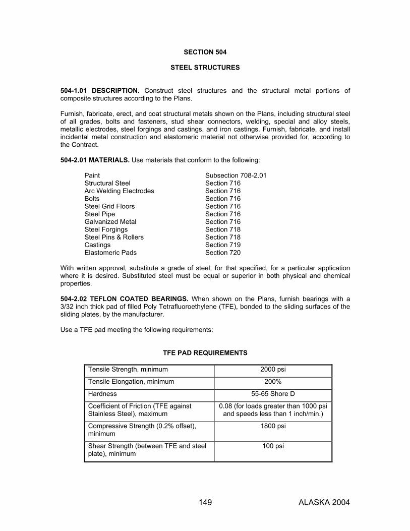
149 ALASKA 2004
SECTION 504
STEEL STRUCTURES 504-1.01 DESCRIPTION. Construct steel structures and the structural metal portions of composite structures according to the Plans. Furnish, fabricate, erect, and coat structural metals shown on the Plans, including structural steel of all grades, bolts and fasteners, stud shear connectors, welding, special and alloy steels, metallic electrodes, steel forgings and castings, and iron castings. Furnish, fabricate, and install incidental metal construction and elastomeric material not otherwise provided for, according to the Contract. 504-2.01 MATERIALS. Use materials that conform to the following:
Paint Subsection 708-2.01 Structural Steel Section 716 Arc Welding Electrodes Section 716 Bolts Section 716 Steel Grid Floors Section 716 Steel Pipe Section 716 Galvanized Metal Section 716 Steel Forgings Section 718 Steel Pins & Rollers Section 718 Castings Section 719 Elastomeric Pads Section 720
With written approval, substitute a grade of steel, for that specified, for a particular application where it is desired. Substituted steel must be equal or superior in both physical and chemical properties. 504-2.02 TEFLON COATED BEARINGS. When shown on the Plans, furnish bearings with a 3/32 inch thick pad of filled Poly Tetrafluoroethylene (TFE), bonded to the sliding surfaces of the sliding plates, by the manufacturer. Use a TFE pad meeting the following requirements:
TFE PAD REQUIREMENTS
Tensile Strength, minimum 2000 psi
Tensile Elongation, minimum 200%
Hardness 55-65 Shore D
Coefficient of Friction (TFE against Stainless Steel), maximum
0.08 (for loads greater than 1000 psi and speeds less than 1 inch/min.)
Compressive Strength (0.2% offset), minimum
1800 psi
Shear Strength (between TFE and steel plate), minimum
100 psi

SECTION 504
ALASKA 2004 150
CONSTRUCTION REQUIREMENTS 504-3.01 FABRICATION. 1. Shop Inspection. Furnish 30 days notice of when work will begin at the fabrication shop to
allow for an inspection.
Furnish 4 signed copies of mill reports covering all steel used on the project. 2. General. Fabricate steel main members subject to tensile stress and fracture critical
members, except for rolled shapes, at a plant certified under the American Institute of Steel Construction (AISC) Quality Certification Program as “Major Steel Bridge,” with endorsement “F.”
Provide workmanship and finish that equal the best general practice in modern bridge shops. Neatly finish portions of the work exposed to view. Carefully and accurately perform shearing, flame cutting, and chipping.
Store plain or fabricated structural material at the fabricating shop above the ground on platforms, skids, or other supports. Keep it free from dirt, grease, or other foreign matter. Protect it from corrosion.
Ensure that rolled material is straight before being laid off or worked. If straightening is necessary, use methods that will not injure the metal. Do not use material with sharp kinks or bends. Steel or wrought iron may be flame cut provided a mechanical guide is used to secure a smooth surface. Flame cut by hand only where approved, and smooth the surface by planing, chipping, or grinding. Manipulate the cutting flame to avoid cutting beyond the prescribed lines. Fillet re-entrant cuts to a radius of at least 3/4 inch. Ensure that finished members are true to line and free from twists, bends, and open joints. Plane sheared edges of plates more than 5/8 inch thick and carrying calculated stresses to a depth of 1/4 inch deep. Fillet re-entrant cuts before cutting. Make sure the surface finish of bearing and base plates and other bearing surfaces that will contact each other or concrete meets the surface roughness requirements as defined in ANSI/ASME B-46.1, surface roughness, waviness and lay, Part I:
Steel slabs ANSI 2,000 Heavy plates in contact in shoes to be welded ANSI 1,000 Milled ends of compression members, stiffeners, and fillers ANSI 500 Bridge rollers and rockers ANSI 250 Pins and pin rockers ANSI 125 Slide bearings ANSI 125

SECTION 504
ALASKA 2004 151
Face and bring to an even bearing abutting joints in compression members and girder flanges, and in tension members where specified on the drawings. Where joints are not faced, keep the opening at 1/4 inch or less. Build floor beams, stringers, and girders with end construction angles to the exact length shown on the Plans, as measured between the heels of the connection angles. The permissible tolerance is plus 0 inch to minus 1/16 inch. Where continuity is required, face end connections. Cold bend load-carrying rolled-steel plates as follows:
Take the rolled-steel plates from the stock plates so that the bendline is at right angles to the direction of rolling. Bend until the radius of the bends, measured to the concave face of the metal, is not less, and preferably more, than shown in the following table, where T is the thickness of the plate.
Angle Through Which Plate is Bent Minimum Radius 61-90 degrees 1.0 T
91-120 degrees 1.5 T 121-150 degrees 2.0 T
If a shorter radius is essential, bend the plates when hot, but not shorter than a radius of 1.0 T. Before bending, round the edges of the plate to a radius of 1/16 inch throughout the portion of the plate to be bent.
Fit up and attach end and intermediate stiffeners as shown on the Plans. Do not weld ends of stiffeners and other attachments to flanges unless shown on the Plans. Where called for on the Plans, stress relieve welded members according to the requirements of the AWS specifications.
3. Shop Splices. In addition to those shown on the Plans, girder webs and flanges may contain
a maximum of 2 shop splices per plate per span. Indicate all splices on the shop drawings. These splices are subject to approval and are subject to the following limitations:
Make splices complete penetration butt welds. Grind flange splices flush. Grind web splices flush on the outside face of exterior girders only. Grind parallel to the longitudinal axis of the girder. Do not place a bottom flange splice within the middle third of any span. Use tension flange splices only as shown on the Plans or as approved. Completely weld each element of a girder, such as flange or web, before attaching it to another element. Make all splices at least 6 inches from the nearest stiffener plate. Offset web and flange splices at least 6 inches.
4. Pins and Rollers. Turn pins and rollers to the dimensions shown on the drawings. Keep them
straight, smooth, and free from flaws.

SECTION 504
ALASKA 2004 152
In pins larger than 9 inches in diameter, bore a hole at least 2 inches in diameter full length along the axis. Bore the hole after the forging has cooled to a temperature below the critical range and before it is annealed. Bore under conditions that prevent injury from too rapid cooling. Bore pin holes true to the specified diameter, smooth and straight, at right angles with the axis of the member, and parallel with each other. Finish cut the final surface. Do not vary the distance outside to outside of holes in tension members and inside to inside of holes in compression members more than 1/32 inch from that specified. Bore the holes in built-up members after completing the assembly. The diameter of the pin hole must not exceed that of the pin by more than 1/50 inch, for pins 5 inches or less in diameter, or 1/32 inch for larger pins. Furnish 2 pilot nuts and 2 driving nuts for each size of pin.
5. Bolt Holes. Either drill or punch bolt holes. Make finished bolt holes 1/16 inch larger than the
nominal diameter of the bolt. Ensure holes are clean cut and without burrs or ragged edges. Material with poorly matched holes will be rejected.
When material forming parts of a member is composed of not more than 5 thicknesses of metal, and whenever the thickness of the metal is not greater than 3/4 inch for structural carbon steel or 5/8 inch for alloy steel, either punch or drill the holes to full size.
When there are more than 5 thicknesses or when any of the main material is thicker than 3/4 inch in carbon steel, or 5/8 inch in alloy steel, or when required under paragraph 5 below, subpunch or subdrill the holes 3/16 inch smaller. After assembling, ream them to size or drill them from the solid to full size. For punched holes, the diameter of the die must not exceed the diameter of the punch by more than 1/16 inch. Ream any holes that must be enlarged to admit bolts. Ream holes cylindrical and perpendicular to the member. Direct reamers mechanically, where practicable. Ream and drill using twist drills. Assemble connecting parts requiring reamed or drilled holes and securely hold them while reaming or drilling them. Match mark them before disassembling. Subpunch (or subdrill if required) holes for field connections and field splices of main truss or arch members, continuous beams, towers (each face), bents, plate girders, and rigid frames while assembled in the shop according to paragraph 9 of this Subsection. Obtain approval of the assembly, including camber, alignment, and accuracy of holes and milled joints before beginning reaming. Subpunch and ream holes for floor beam and stringer field end connections to a steel template, or ream them while assembled. When partial assembly is permitted, as provided in paragraph 9 of this Subsection, ream holes for web member connections to steel templates. When using templates to ream field connections of web members of a truss, arch, bent or tower, mill or scribe at least one end of each web member normal to the long axis of the member. Accurately set the templates at both ends from this milled or scribed end. Accurately set and locate templates for reaming gussets of a truss before reaming or drilling them to their true geometric dimensions, as shown on the shop plans.

SECTION 504
ALASKA 2004 153
Ream or drill the full size of the field connection through templates after carefully locating the templates as to position and angle and firmly bolting them. Use exact duplicate templates used to ream matching members or the opposite faces of one member. Accurately locate templates for connections that duplicate so that like members are duplicates and require no matchmarking. Accurately punch holes full-size, subpunch them, or subdrill them so that after assembling (before reaming), a cylindrical pin 1/8 inch smaller in diameter than the nominal size of the punched hole may be entered perpendicular to the face of the member, without drifting, in at least 75% of the contiguous holes in the same plane. If the requirement is not fulfilled, the badly punched pieces will be rejected. If any hole will not pass a pin 3/16 inch smaller in diameter than the nominal size of the punched hole, the material will be rejected. Ream or drill holes so that 85% of the holes in any contiguous group after being reamed or drilled show no offset greater than 1/32 inch between adjacent thicknesses of metal. Provide in steel templates hardened steel bushings in holes accurately dimensioned from the center lines of the connection as inscribed on the template. Use the center lines to locate accurately the template from the milled or scribed ends of the members.
6. Shop Assembling. Except as modified below, assemble in the shop each main truss, arch
member, continuous beam, tower (each face), bent plate girder, and rigid frame. Make milled ends of compression members in full bearing before starting reaming. Completely shop assemble an entire structure, including floor system, when indicated on the Plans or in the Special Provisions. When the Plans or Special Provisions indicate “partial assembly,” assemble trusses, continuous beams, plate girders, and open spandrel arches in lengths of 3 or more abutting panels. The assembled length must be at least 150 feet.
Clean metal surfaces in contact before assembling them. Assemble, pin well, and firmly draw together the parts of a member with bolts before beginning reaming. Take apart assembled pieces, if necessary, to remove burrs and shavings produced by reaming. Keep the members free of twists, bends, and other deformities. To prepare to shop bolt material punched full-size, spear-ream the bolt holes, if necessary, to admit the bolts. Make the reamed holes no more than 1/16 inch larger than the nominal diameter of the bolts. Secure end connection angles, stiffeners, and similar parts using shipping bolts to prevent damage in shipment and handling. Furnish a camber diagram showing the camber at each panel for each truss. Take the camber from actual measurement while the truss is assembled, or base it on calculated values when full assembly is not required. Allow holes to drift during assembly only as needed to position the parts, and not enough to enlarge the holes or distort the metal. To enlarge holes to admit the bolts, ream them. Match mark connecting parts assembled in the shop to allow for reaming holes in field connections. Furnish to the Engineer a diagram showing the marks.
7. Bolted Connections, High-Strength Bolts. Determine bolt lengths by adding the values given
in Table 504-1 to the total thickness of connected material. These values compensate for thickness of nut, bolt point, and washers. Add 5/32 inch to the grip length per each additional flat washer. Adjust the total length to the next longer 1/4 inch increment up to a 5 inch length and to the next longer 1/2 inch increment for lengths over 5 inches.

SECTION 504
ALASKA 2004 154
Fit bolted parts solidly together when assembling them and do not separate them by gaskets or other interposed compressible material. Place hardened washers under the turned element.
TABLE 504-1
BOLT LENGTH DETERMINATION
Bolt Diameter (inches)
Added Length (inches)
1/2 11/16 5/8 7/8 3/4 1 7/8 1-1/8 1 1-1/4
1-1/8 1-1/2 1-1/4 1-5/8
Keep assembled joint surfaces, including those adjacent to washers, free of scale except tight mill scale. Clean off dirt, loose rust, burrs, and other defects that would prevent the parts from seating. Keep contact surfaces free of oil, paint, or lacquer. When the outer face of the bolted parts has a slope of more than 1:20, use a smooth beveled washer in contact with the sloped surface. Tighten fasteners to give at least the required minimum tension values shown in Table 504-2 when the joint is completed. Use bolts and nuts made by the same manufacturer in a connection.
TABLE 504-2
REQUIRED BOLT TENSION
Bolt Size (inches)
Required Minimum Tension (pounds)
3/4 28,400 7/8 39,250 1 51,500
To achieve the minimum tension values shown in Table 504-2, use direct load indicating washers that conform to ASTM F 959. Demonstrate the suitability of the device by testing a representative sample of at least three devices for each diameter and grade of fastener used in the structure. Test with a calibration device capable of indicating bolt tension. Include in the test assembly flat, hardened washers, if required in the actual connection, arranged as those in the actual connection to be tensioned. Demonstrate with the calibration test that the device indicates a tension at least 5% greater than that required by Table 504-2. Follow manufacturer's installation procedures when installing bolts in the calibration device and in all connections. Be careful to properly install flat, hardened washers when using load indicating devices with bolts installed in oversized or slotted holes and when using the load indicating devices under the turned element. The load indicating device will count as one washer for the purpose of determining bolt length. Place the load indicating device under the bolt head and turn only the nut when tightening the bolt. The device must indicate full tensioning of the bolt when the opening reaches zero. Install bolts in all holes of the connection and bring them to a snug tight condition. Then, tighten fasteners, progressing systematically from the most rigid part (usually near the center)
SECTION 504
ALASKA 2004 155
of the connection to the free edges, or as directed. Keep previously tightened fasteners from relaxing. Multiple systematic tightening cycles may be required. Do not reuse high-strength bolts. Remove previously fully tightened bolts that were loosened by tightening adjacent bolts. Replace them with new bolts, nuts, and load indicating devices.
8. Welding. Perform all welding and Nondestructive Examination (NDE) as specified or shown
on the Plans to meet ANSI/AASHTO/AWS Bridge Welding Code D1.5, except meet AWS D1.1 when welding steel poles, piles, tubes, railing, grates, grate frames, deck expansion joints, and existing structures. Prior to welding, submit for approval a welding plan consisting of the following: a. Quality Control personnel qualifications b. Welding Procedure Specifications (WPS) c. Procedure Qualification Records (PQR) d. Welder Performance Qualification Records (WPQR) with documentation of current
welder certification e. Sample daily inspection sheet f. Type and extent of NDE to be conducted, as required in the specifications Perform all Quality Control inspection necessary to ensure the materials and workmanship meet the requirements of the contract documents. Correct all deficiencies in materials and workmanship revealed by Quality Control and Quality Assurance inspections without additional compensation. Furnish all completed Quality Control inspection documents to the Quality Assurance representative designated by the State. Follow Charpy V-notch impact test requirements as shown on the Plans, except that the impact energy values for filler metals must not be less than that of the base metals to be joined, when tested at the same temperature as the base metal.
504-3.02 ERECTION. 1. General. Provide the falsework and all tools, machinery, and appliances, including driftpins
and fitting-up bolts, needed to perform the work efficiently. Erect the structural steel, remove the temporary construction, and do the work to complete the structure, as required by the Contract and according to these Plans and Specifications. Make temporary field welds to structural steel according to the procedures required by these Specifications. Steel with sharp kinks or bends will be rejected. Heat straightening of A 514 or A 517 steel will be governed by special provision when used.
Install stud shear connectors on beams, stringers, girders, diaphragms, and other surfaces that may be used as walkways. Install stud shear connectors after erecting the structural steel and placing the concrete deck forms and before placing the deck reinforcing steel.
2. Handling and Storing Materials. Store material on skids above the ground. Keep it clean and
properly drained. Place girders and beams upright and shore them. Adequately support long members, such as columns and chords, on skids to prevent injury from deflection.
3. Falsework. Use falsework according to Section 512.
SECTION 504
ALASKA 2004 156
4. Method and Equipment. Before starting erection work, inform the Engineer of the proposed erection method and the proposed amount and character of the equipment.
Follow handling and erection procedures so as to avoid inducing critical buckling stresses in the girders. Submit plans for approval showing the erection method. For trusses, except for simple span trusses supported throughout by falsework during erection, submit stress sheets showing the calculated stresses and deflections resulting from the planned erection sequence. Revise the truss as necessary to suit this erection method. Furnish stress sheets and deflection diagrams for any other unusual design or erection method. The above methods and equipment are subject to the Engineer’s approval. However, even with this approval, maintain responsibility for the safety of the method or equipment and complete the work according to the Plans and Specifications. Obtain approval before doing any work.
5. Straightening Bent Material. Straighten plates and angles or other shapes using methods not
likely to fracture or injure the material. Heat the metal only when the Engineer permits. Do not heat to a higher temperature than what produces a “dark, cherry-red” color.
After heating, cool the metal as slowly as possible. After straightening a bend or buckle, carefully inspect the metal surface for fractures.
6. Assembling Steel. Accurately assemble the parts as shown on the Plans and follow match-
marks. Handle the material carefully to avoid bending, breaking, or otherwise damaging the parts. Do not hammer if doing so will injure or distort the members. Clean bearing surfaces and surfaces to be in permanent contact before assembling the members. Unless erecting by the cantilever method, erect truss spans on blocking placed to give the trusses proper camber. Leave the blocking in place until the tension chord splices have been fully bolted and pinned and all other truss connections have been bolted. Wait to tighten the bolts in splices of butt joints of compression members and bolts in railing until the span has been swung. Fit up and tighten bolted joints as specified in Subsection 504-3.01.7.
7. Pin Connections. Furnish pilot and driving nuts for use in driving pins. Drive pins so that the
members will take full bearing on them. Screw up tight and secure pin nuts as shown on the Plans.
8. Setting Shoes and Bearings. Place shoes, bearing plates, and elastomeric bearing pads set
directly on concrete surfaces on properly finished bearing areas. Float the concrete surfaces on a level plane that varies no more than 1/16 inch from a straightedge placed in any direction across the area. Limit the variation of the finished surface to 1/8 inch from the elevation shown on the Plans. Set the shoes, elastomeric bearing pads, and bearing plates as shown on the Plans in exact position with full and even bearing.
Place under masonry plates grout that meets Subsection 701-2.03. Mix and place grout according to the manufacturer’s written recommendations. Clean concrete areas that will contact the grout. Remove loose or foreign matter that would prevent the bond between the mortar and the concrete surfaces. Tightly pack the grout under the masonry plates to provide full bearing. After placing, cover exposed surfaces of grout pads with a heavy thickness of burlap saturated with water for 3 days. Do not place a load on the grout until it has attained a compressive strength of 5000 psi.

SECTION 504
ALASKA 2004 157
Locate the anchor bolts in relation to the slotted holes in the expansion shoes to correspond with the temperature during erection. Adjust the nuts on anchor bolts at the expansion ends of spans to permit the span to move freely. Apply epoxy adhesive, meeting AASHTO M 235, to the bottom surface of the elastomeric bearing pads before placing them. Do not move the pad until the epoxy has cured and full adhesion is achieved.
9. Attachment of Formwork. When approved, use 1-inch maximum diameter holes in steel
girder webs for attaching formwork. Place holes 6 inches minimum clear distance from all horizontal or vertical welds and space them at least 4 feet center to center. Drill or subpunch and ream holes. They may be left open.
Include in the request enough detail of the formwork for determining the stresses that will be imposed on the girder.
504-3.03 PAINTING. 1. Preparing Metal Surfaces for Painting. Prepare metal surfaces according to Specification
SSPC-SP 10, Near White Blast Cleaning to a profile depth of 1 to 3 mils. Use a profile comparator to ensure minimum profile depth. Do not reuse sand or flint abrasives.
Clean grit or shot of contamination before reusing it. Blow dust and grit from the surface with clean dry air. Remove weld spatter and round sharp edges to a smooth curve. To remove contamination, jet wash or scrub with a stiff brush and clear water or brush blast. Remove light rust with a steel brush or mechanical tool.
2. Schedule of Paint Coats for Metals. Unless otherwise specified, if structural steel will be
exposed to weathering, shop-paint it at least 3 coats: prime coat, intermediate coat, and finish coat.
3. Painting Metal Surfaces.
a. Time of Application. Apply 1 or more applications of prime coat. Apply the initial application within 4 hours after blast cleaning. Allow at least 30 minutes of drying time between primer applications. Before painting and after preparing the surface, remove any oil, grease, soil, dust, or foreign matter on the surface. If rusting occurs after the surface is prepared, clean the surface again.
Avoid contaminating cleaned surfaces with salts, acids, alkali, or other corrosive chemicals before applying the prime coat and between applications of the remaining coats of paint. Remove any contamination from the surface.
b. Storage of Paint and Thinner. Store paint and thinner in a separate building or in a room
that is well ventilated and free from excessive heat, sparks, flame, or direct sun rays. Keep paints susceptible to damage from freezing in a heated storage space when necessary.
Leave paint containers unopened until required for use. Use open containers first. Seal left-over, partial containers. Do not use paint that has begun to polymerize, solidify, gel, or deteriorate.

SECTION 504
ALASKA 2004 158
c. Mixing and Thinning. Mix paint thoroughly before use and agitate often during application. Do not transfer paint mixed in the original container until all settled pigment is incorporated into the vehicle. Pouring off part of the vehicle temporarily to simplify mixing, is permitted. Mix by mechanical methods, except use hand mixing for containers up to 5 gallons. Do not use an air stream bubbling under the paint surface to mix paint or keep it in suspension. Remove and discard any skin that has formed in the container. Do not use the paint if the skin exceeds 2% of the paint volume. When mixing paint, break up all lumps, completely disperse settled pigment, and create a uniform composition. If mixing by hand, pour off most of the vehicle into a clean container. Lift the pigment in the paint from the bottom of the container using a broad, flat paddle. Break up lumps and thoroughly mix the pigment with the vehicle. Return the poured-off vehicle to the paint by simultaneously stirring or pouring repeatedly from one container to another until the composition is uniform. Inspect the bottom of the container for unmixed pigment. Wet tinting pastes or colors with a small amount of thinner, vehicle, or paint and thoroughly mix them. Add the thinned mixture to the large container of paint and mix until the color is uniform. If paint does not have a limited pot life, or does not deteriorate on standing, mix it at any time before use. However, if it has settled, remix it immediately before use. Do not keep paint in spray pots, painters' buckets, etc., overnight. Gather it into a container and remix it before use. When the engineer deems it necessary to obtain satisfactory application, add paint thinner according to the manufacturer's instructions.
d. Application of Paint. Use the oldest of each kind of paint first. Apply paint by spraying.
Use brushes, daubers, or sheepskins when no other method can properly apply paint in difficult access areas. Use dipping, roller coating, or flow coating only when authorized. Blast clean all areas with mudcracking in the zinc-rich primer and then paint them with primer to the specified thickness. After applying the prime coat, apply the intermediate and finish coats to exposed surfaces according to the manufacturer's recommendations. Apply the intermediate coat in 2 applications. Apply the first application as a mist coat. Apply the second application after the mist coat has dried to a set-to-touch condition. Apply the finish coat in 1 application. Apply paint within the environmental limitations specified by the coating manufacturer. Do not apply paint when the temperature of the steel surface is less than 40 °F or more than 125 °F. Do not apply paint in fog or mist, when it is raining or snowing, or when the relative humidity exceeds the manufacturer’s recommendations. Do not apply paint to wet or damp surfaces. Do not apply paint on frosted or ice-coated surfaces.

SECTION 504
ALASKA 2004 159
With approval, apply paint in damp or cold weather, and only under the following conditions. Paint the steel under cover and protect and shelter it, or heat the surrounding air and the steel to a satisfactory temperature. Meet the above temperature and humidity conditions. Keep the steel under cover or protected until it is dry or until weather conditions permit its exposure. Allow to dry any applied paint exposed to freezing, excess humidity, rain, snow, or condensation. Then, remove damaged areas of paint, prepare the surface again, and repaint it with the same kind as the undamaged areas. Stripe paint before applying each coat of paint. Spot paint edges, corners, crevices, rivets, bolts, welds, and sharp edges before applying the full coat of paint on the steel. Extend striping for at least 1 inch from the edge. Let this stripe coat dry before applying the full coat, if possible. Otherwise, set-to-touch the stripe coat before applying the full coat. However, do not permit the stripe coat to dry long enough to allow the unprimed steel to rust. Apply each coat of paint as a continuous film of uniform thickness, free of pores. Repaint any thin spots or areas missed in the application. Allow them to dry before applying the next coat. Wait until each coat of paint is in the proper state of cure or dryness before applying the next coat. Ensure a minimum dry film thickness of 3 mils and a maximum dry film thickness of 5 mils for each coat of paint. The dry film thickness of the paint will be measured in place with a calibrated magnetic film thickness gauge. If any coat of paint is thinner than specified, obtain the minimum dry film thickness by applying additional coats of paint. A Tooke gauge may be used to perform destructive testing of each coat’s dry film thickness. Repair damaged areas.
e. Brush Application. Brush paint areas inaccessible to a spray gun. Work paint into
crevices and corners. Paint surfaces not accessible to brushes using daubers or sheepskins. Brush out runs or sags. Leave a minimum of brush marks in the applied paint.
f. Spray Application of Paint. To apply paint by spraying, use equipment capable of properly
atomizing the paint to be applied. Use equipment with pressure regulators and gauges and use air caps, nozzles, and needles recommended by the equipment manufacturer for the material being sprayed. Keep the equipment in satisfactory condition to permit proper paint application. In closed or recirculating paint spray systems, where gas is used under pressure over the liquid, use an inert gas, such as nitrogen. Provide adequately sized traps or separators to remove oil and water from the compressed air. Drain them periodically during operations. Ensure that the air from the spray gun impinging against the surface shows no water or oil. Keep paint ingredients properly mixed in the spray pots or containers while applying the paint. Use either continuous mechanical agitation or frequent intermittent agitation. Adjust the pressure on the material in the pot and adjust the air pressure at the gun for optimum spraying effectiveness. Adjust the pressure on the material in the pot when changing the elevation of the gun above the pot. Keep the atomizing air pressure at the

SECTION 504
ALASKA 2004 160
gun high enough to atomize the paint properly but not so high as to cause the paint to fog or the solvent to evaporate, or to cause loss by overspray. Keep spray equipment clean to avoid depositing dirt, dried paint, and other foreign materials in the paint film. Remove any solvents left in the equipment before applying paint to the surface. Apply paint in a uniform layer, overlapping at the edge of the spray pattern. During application, hold the gun perpendicular to the surface and at a distance that will deposit a wet layer of paint on the surface. Release the gun’s trigger at the end of each stroke. Apply coats free of runs, sags, and dry spray.
g. Shop Painting. Perform shop painting after fabrication and before the surface is damaged from weather or other exposure. Do not paint shop contact surfaces. Paint surfaces to be in contact after field erection. Apply only a mist coat (0.5 to 0.8 mil dry film thickness) of inorganic zinc-rich primer, meeting SSPC Paint Specification No. 30, Weld-Through Inorganic Zinc Primer, Class 5, on the following surfaces: 1. High strength bolted connection contact surfaces 2. Top flange steel surfaces 3. Areas within 2 inches from the edges to be welded 4. Areas where the full 3 coats of paint will interfere with field assembly Apply the full paint coats specified to steel surfaces that will contact wood. Remove anti-weld spatter coatings before painting. Before abrasive blasting, grind smooth all metal defects, fins, slivers, burrs, weld spatter, and sharp edges from shearing or similar operations, including flame hardened edges from cutting or burning. Grind flame hardened edges to a 1/16 inch minimum radius. Repair defects that become evident after abrasive blasting or prime coat application. Retexture the surface to match the blasted profile. Copy erection marks and weight marks on areas that have been previously painted with the shop coat.
h. Field Painting. If steel surfaces have not received the full paint coats, paint them as soon as possible after erection. Touch up metal that has been shop coated with the same type of paint as the shop coat. Touch up by cleaning and painting field connections, welds, bolts and all damaged or defective paint and rusted areas. If concreting or other operations damage any paint, clean the surface and repaint it. Remove concrete spatter and drippings before applying paint. Protect wet paint against damage from dust or other detrimental foreign matter.
i. Drying of Painted Metal. Allow the paint to dry before recoating or exposing it. Do not add a dryer to paint on the job unless the paint specification calls for one. Do not immerse painted metal until the paint has dried. Protect paint from rain, condensation, contamination, snow, and freezing until dry.
SECTION 504
ALASKA 2004 161
j. Handling of Painted Steel. Do not handle painted steel until the paint has dried except for
turning it for painting or stacking it for drying. Minimize damage to paint films from stacking steel members.
Remove paint that is damaged during handling and touch it up with the same number of coats and kinds of paint previously applied. Wait until painted steel is dry before loading it for shipment. Repair damaged galvanized coating per AASHTO M 36, Section 11. Use inorganic zinc rich primer meeting Subsection 708-2.01.
k. System Durability and Certification. Have the coating manufacturer review the project and
the proposed service environment and issue you written recommendations and instructions to properly prepare the surface, apply the coating, and achieve maximum durability on this project. Certify to the Department that the system was applied according to the manufacturer’s recommendations and instructions. Enclose a copy of the recommendations and instructions with the certificate.
504-3.04 CLEANUP. Upon completion and before final acceptance of the structure, remove falsework and falsework piling down to 2 feet below the finished ground line. 504-4.01 METHOD OF MEASUREMENT. Section 109 and as follows: Structural steel measured by weight, will include castings, forgings, alloy steels, steel plates, high-strength bolts and nuts, anchor bolts and nuts, stud shear connectors, shoes, rockers, rollers, pins and nuts, expansion dams, roadway drains and scuppers, weld metal, and structural shapes for expansion joints and pier protection. The weight of the metal in the completed structure will be computed, based on the following: 1. Unit Weights, pounds per cubic foot:
Aluminum, cast or rolled 173 Bronze or copper alloy 536 Copper sheet 558 Iron, cast 445 Iron, malleable 470 Lead, sheet 707 Steel, cast or rolled, including alloy, copper bearing, and stainless 490 Zinc 450
2. Shapes, Plates, Railing and Flooring. By their nominal weights and dimensions as shown on the contract drawings, deducting for copes, cuts and open holes, exclusive of bolt holes. The weights of plates more than 36 inches wide will include an estimated overrun computed as one-half the “permissible variation in thickness and weight” as tabulated in ASTM A 6. The weight of railing will be included as structural steel unless the bid schedule contains a pay item for bridge railing under Section 507. The weight of steel grid flooring will be computed separately.

SECTION 504
ALASKA 2004 162
3. Castings. From the dimensions shown on the Plans, deducting for open holes. To this weight will be added 5% for fillets and overruns. Scale weights may be used for castings of small complex parts, since it would be difficult to compute their weight accurately.
4. Welds. From the following for shop and fillet welds:
Size of weld (inches) Pounds per linear foot
1/4 0.20 5/16 0.25 3/8 0.35 1/2 0.55 5/8 0.80 3/4 1.10 7/8 1.50 1 2.00
The weight of other welds will be computed on the basis of the theoretical volume from dimensions of the welds, adding 50% to the weight to allow for overrun.
5. High-Strength Bolts. From the following for bolt heads and nuts for high-strength bolts:
Bolt Diameter (inches) Pounds per 100 Heads or Nuts
5/8 15 3/4 25 7/8 37 1 50 1-1/8 75
6. Excluded Items. The weight of the following will not be measured: erection bolts, shop and
field paint, galvanizing; boxes, crates, and other containers used for shipping; together with sills, struts, and rods used for supporting members during transportation; and bridge hardware connectors used for joining timber members.
504-5.01 BASIS OF PAYMENT. If no pay item is included in the bid schedule for structural steel, the quantities of metal drains, scuppers, conduits, ducts and structural shapes for expansion joints and pier protection measured as provided above, will be paid for as reinforcing steel under Section 503. No additional payment will be made for increases in structural steel quantities due to your erection method. Structural steel for precast or prestressed concrete bridges is subsidiary. Payment will be made under:
Pay Item Pay Unit 504(1) Structural Steel Lump Sum 504(2) Structural Steel Pound

163 ALASKA 2004
SECTION 505
PILING 505-1.01 DESCRIPTION. Furnish and drive piles, including test piles, as specified. Furnish piles sufficient in length to obtain the required ultimate bearing capacity and to extend to the minimum tip elevation shown on the Plans. Drive additional test piles, make borings, or make other investigations needed to determine pile lengths required, without extra compensation. 505-2.01 MATERIALS. Use materials that conform to the following:
Concrete Section 501 Reinforcing Steel Section 709 Timber Piles Section 713 Preservatives for Timber Section 714 Steel Shell Section 715 Steel Pipe Section 715 Structural Steel Piles Section 715 Sheet Piles Section 715
CONSTRUCTION REQUIREMENTS 505-3.01 TEST PILES. When called for in the bid schedule, furnish and drive test piles at the locations designated. Drive test piles to the specified tip elevation or bearing value, as directed, and as follows: 1. Before driving the pile, excavate the ground at the test piles to the elevation of the bottom of
the footing. 2. Drive test piles using the same hammer you will use for service piles. 3. Drive required test piles before beginning any other pile driving work on the structure. Test piles may be included as part of the completed structure if they conform to the requirements for service piles. Cut off test piles not included in the completed structure as directed. 505-3.02 LOAD TESTS. When called for on the Plans, perform pile load tests according to the Special Provisions. 505-3.03 PILE BEARING VALUES. Drive piles to the required ultimate bearing capacity. The required ultimate bearing capacity is the design pile load as indicated on the Plans multiplied by a factor of safety. The Engineer will determine the pile driving criteria using wave equation analysis. When the wave equation is not used, drive all piles to a bearing value not less than the design load, as shown on the Plans. When called for in the bid schedule, check bearing values using load tests as specified above. Determine the safe bearing value of each pile using the applicable dynamic formula from those listed below. 1. Gravity hammers: P = 2WH S+1

SECTION 505
ALASKA 2004 164
2. Single-acting hammers with unrestricted rebound of ram: P = 2WH S+0.1 3. Double-acting hammers with enclosed rams: P = 2E S+0.1 Where: P = Safe bearing value, in pounds
W = Weight of the striking parts of the hammer, in pounds H = Effective height or fall of the ram, in feet S = Average penetration per blow, in inches, for the last 5 to 10 blows for gravity
hammers and the last 10 to 20 blows for steam, air, or diesel hammers E = The actual energy delivery by the hammer per blow, in foot-pounds
The above formulas are applicable only when 1. the hammer has free fall, 2. the head of the pile is square and in good condition, 3. the penetration rate is reasonably quick and uniform, 4. there is no appreciable bounce of gravity hammers after the blow, and 5. a follower is not used. If there is appreciable bounce for gravity hammers, deduct twice the height of bounce from H to determine its value in the formula. 505-3.04 JETTED PILES. Do not use jets during the test blows when determining the safe bearing values of jetted piles. 505-3.05 MINIMUM PENETRATION. Make all efforts to drive each pile to the minimum desirable tip elevation and to the desired bearing, as shown on the Plans. 505-3.06 CAST-IN-PLACE CONCRETE PILES. Build cast-in-place concrete piles to the design shown on the Plans. Drive steel shells or pipes and fill with Class A Concrete. Use the type of steel shell or closed-end pipe and the minimum thicknesses of material shown on the Plans. Do not allow water to freeze in cylinder-type piles. Before placing concrete, inspect the shells for damage or distortion. Furnish a suitable light for this purpose. Do not fill shells or pipe with concrete until all adjacent shells, pipes, or piles within a radius of 5 feet or 4.5 times the average pile diameter, whichever is greater, have been driven to the required resistance. Place concrete as follows: 1. Remove all water and foreign material from shells and pipes. 2. Place the concrete in one continuous operation from bottom to top. Concrete may be
discharged directly into the pile and permitted to free-fall into place. 3. Use interior reinforcement where shown on the Plans. 4. Vibrate the top 20 feet of concrete.

SECTION 505
ALASKA 2004 165
5. After filling a shell or pipe with concrete, do not drive any shell, pipe, or pile within 20 feet for at least 7 days after filling.
505-3.07 EXTENSIONS, SPLICES, AND BUILD-UPS. When necessary, make extensions, splices, and build-ups as shown on the Plans and according to the following: 1. Steel Piles. If the length of a steel pile is not sufficient to obtain the required bearing capacity,
splice an additional length to it. Use additions with cross sections identical to the pile cross sections.
Make splices with complete penetration butt welds over the entire cross section. If approved, piles may be spliced using pile cut-offs and short pieces if no piece used is less than 10 feet long.
2. Shell or Pipe for Cast-in-Place Piles. If pile shell or pipe must be extended to reach desired
penetration or required bearing capacity, splice additional lengths to the shell or pipe using complete penetration butt welds over the entire cross section or other splice details recommended by the manufacturer and approved.
Meet the welding requirements of Subsection 504-3.01.8. 505-3.08 TIMBER PILE BENTS. Distribute piles of various sizes within each bent to obtain uniform strength and rigidity in the bents of each structure and to avoid undue bending or distortion of the sway bracing. Make accurate cut-offs to ensure full bearing between the caps and piles. 505-3.09 DRIVING PILES. Size the pile driving equipment to drive the piles to the required minimum depth and ultimate bearing capacity without damage. Use the approved hammer and pile cushions recommended in the hammer manufacturer’s guidelines. Limit the compressive driving stresses as indicated by a wave equation analysis to 90% of the pile yield stress. Submit a pile driving plan at least 15 days before driving piles. Include a completed Pile Driving Equipment Data (Form 25D-098) and any attachments necessary to describe all pile driving equipment and techniques to be used. The Department will base approval of the pile driving equipment on a wave equation analysis and the Engineer’s recommendations. Submit changes to the approved pile driving plan on a revised Pile Driving Equipment Data form with necessary attachments. Allow at least 5 working days for the Engineer’s approval. Steel piles when placed in the leads must not exceed the camber and sweep permitted by allowable mill tolerance. Piles bent or otherwise injured will be rejected. Drive all piles as shown on the Plans or as ordered in writing. Drive abutment piles and pier piles in footings within an allowed variation as to direction of pile of not more than 1/4 inch per foot. Position the piles at the bottom of the footing within 6 inches of the position shown on the Plans. Do not vary the distance between any 2 piles more than 6 inches from that shown on the Plans, and keep the clear distance from the edge of pile to the edge of footing to at least 9 inches. Place exposed pile bents within 1/2 inch of the plan position at cut-off elevation and within 3 inches of the plan position at the original ground line elevation. Limit the rotation of such steel piles about their longitudinal axis to 15 degrees from the plan position. Install piles in groups starting from the center of the group and proceed outward in either direction. Use a metal collar on every timber pile, except when the head is fitted into a steel head block. Protect the heads of the piles with caps of approved design, when needed.

SECTION 505
ALASKA 2004 166
Provide driving heads, mandrels, or other devices according to the manufacturer’s recommendations so that the pile may be driven without damage. Use cast steel combination driving heads and pilots with suitable cushion blocks. Ensure that the driving heads closely fit the top of a steel H-pile or steel pipe pile, and cut the steel piles squarely. Provide a driving cap to hold the axis of the pile in line with the axis of the hammer. Use full-length piles where practical. Where splices are required, follow the provisions of Subsection 505-3.07. Use metal shoes or reinforced tips of the design shown on the Plans or as ordered in writing. Use impact hammers or a combination of hammers to drive piles. However, with written permission, use gravity hammers to drive timber piles. The Department will consider the use of vibratory hammers when requested by the Contractor and when circumstances permit the determination of bearing capacity and required penetration by means other than a dynamic driving formula. Remove inefficient hammers from the work. Do not use followers to drive piles. Use pile driver leads that allow the hammer to move freely. To ensure rigid lateral support to the pile during driving, hold the pile driver leads in position at the top and bottom by using guys or steel braces or by securely fastening them to the ground. Except where piles are driven through water, use leads that are long enough to avoid using a follower. The design of the leads must permit proper placing of batter piles. If you cannot obtain the desirable penetration shown on the Plans by using the specified driving methods and equipment, or if the Engineer believes structural damage to the piling is likely to result from continuing these methods, attempt other methods (as approved in writing) to obtain penetration. These methods may include, but are not necessarily limited to: 1. Pre-boring 2. Blasting 3. Spudding 4. Jetting 5. Using a heavier or faster striking hammer Attempt all approved methods before starting work on more than 5 piles or 50% of the piles, whichever is lesser, in any one substructure unit (such as pier or abutment), or within a 30 foot length of retaining wall. After exhausting all practicable means to obtain the desired penetration but without success, the Engineer may consider accepting the piling at a lesser penetration if the Engineer believes the adequacy and safety of the resulting structure will not be jeopardized by such acceptance. Obtain written approval before employing any alternative methods of pile driving or variations from the desirable tip elevation accepted. When driving piles through new embankment and the depth of the embankment at the pile location is in excess of 5 feet, drive the pile in a hole made through the embankment. Make the hole diameter not less than the nominal size of the pile plus 6 inches. After driving the pile, fill the annular space around the pile with dry sand or pea gravel. Dispose of excess excavated material as provided in Subsection 203-3.01. 505-3.10 DEFECTIVE PILES. Use a pile driving method which does not subject the piles to excessive and undue abuse producing crushing and spalling of the concrete, injurious splitting, splintering, and brooming of the wood or deformation of the steel. Do not manipulate the piles to force them into proper position. Correct damaged or improperly driven piles by one of the following approved methods:
SECTION 505
ALASKA 2004 167
1. Withdraw and replace the pile with a new and, when necessary, longer pile. 2. Drive a second pile adjacent to the defective pile. 3. Splice or build up the pile as provided in Subsection 505-3.07, or extend a sufficient portion of
the footing to properly imbed the pile. Do not splice timber piles without specific permission. Drive down all piles pushed up by driving adjacent piles or by any other cause.
505-3.11 CUTTING OFF PILES. Cut off the piles at the elevations indicated on the Plans. Ensure that all injured material is removed. 505-3.12 PROTECTING TREATED TIMBER PILES. Carefully handle the treated piles. Do not drop the piles, break the outer fibers, bruise the surface, or penetrate the piles with tools. Carefully trim all cuts and abrasions in treated piles and coat with at least 3 applications of hot creosote oil and cover with hot roofing pitch. Treat all bolt holes according to AWPA standards before driving bolts. After treating the holes, plug all unfilled holes with treated plugs. After cutting each treated pile to receive the cap, give the sawed surface 3 coats of hot creosote oil. Cover it with hot tar pitch and place 2 layers of 20 inches x 20 inches heavy canvas saturated with hot pitch over the surface. Place a 28 gage galvanized metal cover which overlaps the pile at least 6 inches in each direction. Bend the metal cover down over the edges and secure it with galvanized roofing nails. 505-3.13 COATING OF STEEL PILES AND SHELLS. Galvanize steel piles and steel pile shells from the top to a distance not less than 10 feet below the ground line. Galvanize according to AASHTO M 111 and to a thickness of 4 mils. Steel piles and pile shells that do not protrude above the final ground line do not require galvanizing. 505-4.01 METHOD OF MEASUREMENT. Section 109 and as follows: Furnish Piles. The sum of the lengths of the piles in place in the completed structure, conforming to the Contract, measured along the centerline of piles from the tip of pile to the intersection with the cut-off elevation shown on the Plans. Drive Piles. The number of piles driven in place in the completed structure conforming to the Contract. Test Piles. The number of test piles driven, as required in the bid schedule or ordered in writing, which are not included in the finished structure as service piles. Load Tests. The number of load tests completed, as required in the bid schedule or ordered in writing. Sheet Piles. The projected area of furnished and driven sheet piles remaining in place in the permanent structure as called for on the Plans, measured in final position. 505-5.01 BASIS OF PAYMENT. Furnish Piles The contract price includes pile materials delivered to the site; pile crew time, including payroll and administrative additives; and equipment rental for the driving crane, leads and hammer. All other costs associated with pile work are paid under Drive Piles. Drive Piles. The contract price includes all items related to pile work that are not included in Furnish Piles, including but not limited to: equipment movements, pile splices, cutoffs, templates, crane or work platforms, pile cleanout, jetting or drilling to specified depths, reinforcing steel, concrete fill, and other fixed or variable items. This pay item is independent of pile length and, therefore, will not change with variations from estimated pile tip elevations. No adjustment in the

SECTION 505
ALASKA 2004 168
contract unit price for Drive Piles, will be made as a result of revisions ordered to the pile tip elevations. Test Piles. Test piles included in the structure as service piles will be paid for at the contract prices for furnishing and driving piles and not as test piles. Sheet Piles. Sheet piles used as temporary shoring for excavation, whether removed or left in place at your option with permission of the Engineer, are subsidiary. Pile shoes, reinforced tips, and splices are subsidiary. Payment will be made under:
Pay Item Pay Unit 505(1) Furnish Untreated Timber Piles Linear Foot 505(2) Drive Untreated Timber Piles Each 505(3) Furnish Treated Timber Piles Linear Foot 505(4) Drive Treated Timber Piles Each 505(5) Furnish Structural Steel Piles Linear Foot 505(6) Drive Structural Steel Piles Each 505(7) Furnish Cast-In-Place Concrete Piles Linear Foot 505(8) Drive Cast-In-Place Concrete Piles Each 505(9) Structural Steel Sheet Piles Square Foot 505(10) Test Piles (Type) Each 505(11) Load Test Each
169 ALASKA 2004
SECTION 506
TIMBER STRUCTURES
506-1.01 DESCRIPTION. Construct timber structures and the timber portions of composite structures. Furnish, prepare, fabricate, erect, treat and/or paint timber and hardware, as specified. 506-2.01 MATERIALS. Use materials that conform to the following:
Timber Section 713 Preservatives for Timber Section 714 Structural Shapes, Rods, and Plates Section 716
Glued-Laminated Timber Members. Construct of Douglas Fir produced and inspected in conformance with the requirements of ANSI/AITC A 190.1. Use laminating adhesives for timber to be used in wet conditions. Use Industrial-Grade glued-laminated members that have been treated with pressure preservative. Bolts, Screws and Drive Spikes. Conform to ASTM A 307 (ANSI/ASME B 18.2.1). Galvanize meeting AASHTO M 232. Use standard timber fasteners manufactured with economy heads and spiral threads as drive spikes for fastening glued-laminated deck panels. Preservatives. Use pressure treatment preservatives for timber bridges as specified. Mastic Sealer. Use Koppers Bitumastic Super Service Black, Chevron Wet Plastic Cement, ATCO 1714 Plastic Fibre Seal, Seal Tight 158 Rubber Asphalt Sealer, or approved equal. Steel Dowels. Use uncoated steel dowels with a minimum yield strength of 36,000 psi on glued-laminated deck panels. Timber Connectors. Conform to the requirements of the AASHTO Standard Specifications for Highway Bridges, Division II, Section 16.2.6, Timber Connectors.
CONSTRUCTION REQUIREMENTS 506-3.01 GENERAL. Employ competent bridge carpenters. Framing must be true and exact. Set the heads of nails and spikes flush with the wood surface. Workmanship on all metal parts must conform to specified requirements. Stack all lumber and timber at the worksite to prevent warping. Open-stack untreated material at least 12 inches above the ground surface so that the pile will shed water. When required, cover untreated timber to protect it from the weather. Close-stack treated timber above the ground on blocks or lagging. Clear weeds and rubbish underneath and around all stacks. Locate all non-removable erection marks on fabricated timber so they are hidden from view in the completed work. Do not drag or drop timber members. Use web-belting slings and chokers to handle timber members. Protect corners with protection angles or blocking at pickup points. The estimated quantity of treated timber shown on the Plans is approximate only and no guarantee is made that it is the exact quantity to be furnished. Glued-laminated timber quantities shown on the Plans indicate gross quantities of timber, based on nominal dimensions and actual lengths before final planing of the laminated member.
SECTION 506
ALASKA 2004 170
506-3.02 TREATED TIMBER. Fabricate timber (including all cutting, shaping, and boring) before treatment. Handle timber carefully without dropping, breaking the outer fibers, or bruising or penetrating the surface with tools. In coastal waters, avoid cutting and boring below the high-water mark. Carefully trim all abrasions and treat all cuts in treated piles according to AWPA standard M 4. Before driving bolts, treat all holes bored after treatment according to the applicable AWPA standards. Plug remaining holes with treated plugs. 506-3.03 UNTREATED TIMBER. In structures of untreated timber, thoroughly coat the following surfaces with an AWPA-approved preservative before the timbers are assembled: 1. Ends, tops, and all contact surfaces of posts, sills, caps, floor beams, and stringers 2. All ends, joints, and contact surfaces of bracing and truss members 3. All surfaces of timber bumpers 4. The back faces of bulkheads 5. All other timber that will come in contact with earth 506-3.04 HOLES FOR BOLTS, DOWELS, RODS, AND LAG SCREWS. Bore holes for round drift-bolts and dowels with a bit 1/16 inch smaller in diameter than the bolt or dowel to be used. Bore holes for square drift-bolts or dowels equal to one side of the bolt or dowel. Bore holes for machine bolts 1/16 inch wider than the bolt. Bore holes for lag screws with a bit not larger than the body of the screw at the root of the thread. Bore holes for deck dowels in glued-laminated timber deck panels 1/2 inch deeper than the dowel embedment and no more than 1/16 inch oversize. 506-3.05 BOLTS AND WASHERS. Use washers of the type and size specified to protect wood from bolt heads and nuts. Use cast-iron washers with a thickness equal to the diameter of the bolt and with a diameter 4 times its thickness. Use malleable or plate washers with diameter or side dimensions of the square equal to 4 times the diameter of the bolt, and thickness equal to 1/2 the diameter of the bolt. Use cast-iron washers when the timber is in contact with the earth. Check or burr all nuts with a pointed tool after final tightening to prevent turning. 506-3.06 COUNTERSINKING. Countersink bolts where smooth faces are required. Paint recesses formed for countersinking, except in railing, with pentachlorophenol or creosote oil. After bolts or screws are in place, fill the recesses with hot pitch or mastic sealer. Countersink fasteners for attaching glu-lam deck panels to their supporting members below the top surface of the deck. After installation, fill all fastener recesses in the top surface of the deck with mastic sealer. 506-3.07 FRAMING. Cut all lumber and timber accurately and frame to a close fit so that the joints bear weight evenly over all contact surfaces without shimming. 506-3.08 FRAMING BENTS. Bed mud sills firmly and evenly to solid bearing. Tamp them in place. Carefully finish concrete pedestals for supporting framed bents so that posts will bear evenly on them. Set dowels for anchoring posts when the concrete is cast. 506-3.09 STRINGERS. Size stringers at bearings and place them in position so that knots near edges are in the top portions of the stringer. Separate the lapped ends of untreated stringers by at least 1/2 inch for air circulation. Securely fasten the lapped ends by drift-bolting where specified. Stagger the joints when stringers are two panels in length.
SECTION 506
171 ALASKA 2004
Securely toe-nail cross-bridging between stringers with at least two nails in each end. Place cross-bridging at the center of each span. 506-3.10 PLANK FLOORS. Lay the planks heart side down. For seasoned material, use 1/4 inch openings between planks. For unseasoned material, use tight joints. Securely spike each plank to each stringer. Carefully grade the planks for thickness and lay them so that adjacent planks vary in thickness by no more than 1/16 inch. 506-3.11 LAMINATED OR STRIP FLOORS. Lay each piece vertically and tightly against the preceding piece. Each piece must bear evenly on all the stringers. Use pieces long enough to bear on at least four stringers. Make end joints on any one stringer no closer than every third piece. Place end joints in adjoining pieces no closer than every second stringer. Coat joints between adjacent glu-lam timber deck panels with mastic sealer before drawing the panels together. 506-3.12 TRUSSES. Check completed trusses to ensure that they show no irregularities of line. Chords must be straight and true from end to end in horizontal projection. Ensure that chords show a smooth curve through panel points conforming to the correct camber in vertical projection. Accurately fit all bearing surfaces and joints. The Engineer will reject pieces with uneven or rough cuts at the points of bearing. 506-3.13 PAINTING. Paint the structure only when specified. 506-4.01 METHOD OF MEASUREMENT. Section 109. 506-5.01 BASIS OF PAYMENT. Mastic sealer, elastomeric bearing pads, and hardware are subsidiary. Structural steel is subsidiary unless shown on the bid schedule. Payment will be made under:
Pay Item Pay Unit 506(1) Treated Timber Lump Sum 506(2) Untreated Timber Lump Sum 506(3) Treated Timber MBM 506(4) Untreated Timber MBM

172 ALASKA 2004
SECTION 507
BRIDGE RAILING 507-1.01 DESCRIPTION. Construct concrete, timber, or steel bridge railing and pedestrian railing as shown on the Plans. Furnish and install bridge number plates as shown on the Plans. 507-2.01 MATERIALS. Use materials that conform to the following:
Steel Railing Section 722 Timber Railing Section 506 Concrete Section 501 Reinforcing steel Subsection 709.-2.01 (Epoxy-Coated)
507-3.01 CONSTRUCTION REQUIREMENTS. 1. General. Construct railing to the line and grade shown on the Plans. Ensure that the rail does
not reflect any unevenness of the bridge structure. Set rail posts normal to the grade. Place railing after all falsework is removed and the span is self-supporting. Do not paint bridge railing.
Furnish and install concrete curbing, associated reinforcing steel, and the approach rail transition bracket for steel bridge railing.
2. Steel. Erect steel railing in conformance with Subsection 504-3.02. Weld in conformance with
Subsection 504-3.01.8. Complete welding before galvanizing the railing. 3. Timber. Fabricate and install timber railing in conformance with Section 506. 4. Concrete. Construct concrete railing to meet applicable requirements of Sections 501 and
503. Base concrete mix design on Class A, except use a minimum 28-day compressive strength of 3000 psi. Apply a rubbed finish to exposed surfaces of concrete.
507-4.01 METHOD OF MEASUREMENT. Section 109. 507-5.01 BASIS OF PAYMENT. The contract price includes all rail elements, rail posts, brackets, spacers, fastenings and anchors required to attach the railing to the structure; concrete and associated reinforcing steel included or partially contained within the limits of the concrete rail section or within the limits of the concrete curb for the steel bridge rail section; and bridge number plates. Payment will be made under:
Pay Item Pay Unit 507(1) Steel Bridge Railing Linear Foot 507(2) Pedestrian Railing Linear Foot 507(3) Thrie Beam Bridge Railing Linear Foot 507(4) Concrete Bridge Railing Linear Foot 507(5) Timber Bridge Railing Linear Foot
173 ALASKA 2004
SECTION 508
WATERPROOFING MEMBRANE 508-1.01 DESCRIPTION. Furnish and install preformed waterproofing membrane on concrete bridge decks, as specified. 508-2.01 MATERIALS. Use materials that conform to the following:
Membrane Material Manufactured type single or multiple component elastomeric material from the Department's Approved Products List.
Pavement Overlay Material Section 401
CONSTRUCTION REQUIREMENTS 508-3.01 APPLICATION OF MEMBRANE WATERPROOFING. 1. General. Install membranes under the on-site supervision of a representative from the
membrane manufacturing company and according to the manufacturer's published instructions. Achieve the following results:
a. Complete bond between the membrane and the concrete surface of deck and curb face b. Unbroken waterproof membrane in place between the concrete deck surface and the
asphalt overlay c. Complete bond between the membrane and the asphalt overlay
2. Preparation of Concrete Deck. Before applying membrane:
a. Ensure that all concrete to receive membranes has achieved at least 80% of the 28 day ultimate strength (f ’c) indicated on the Plans.
b. Ensure that grout in keyways between precast concrete deck components has cured at least 5 days.
c. Remove any contaminants such as grease, oil, or paint with solvents, detergents, or by sand blasting.
d. Correct any sharp concrete edges on the deck surface that may puncture the membrane. e. Power sweep the deck to remove all foreign materials such as dirt, dust, moisture, and
loose concrete. f. Before applying the tack coat, primer, or emulsion, thoroughly clean the deck with
compressed air.
3. Weather and Moisture Limitations. Apply membrane only when:
a. The deck is completely dry b. The temperature of the deck and ambient air is above 40 °F
4. Overlaying and Protection of Membrane. When overlaying membrane, observe the following
requirements:
a. Do not place the asphalt overlay until the membrane has cured enough to prevent damage from the overlaying operation.
b. Do not operate vehicles, except the asphalt paver and trucks used for hauling the asphalt overlay mix, on the membrane.
SECTION 508
ALASKA 2004 174
c. Use only rubber-tired or rubber-tracked paving machines over the membrane. d. Use only steel-wheeled rollers to compact the asphalt paving on the bridge decks. e. Do not use vibratory rollers with vibrator turned on. f. Place, spread, and roll the asphalt so that the membrane will not be damaged. g. Adhere to the manufacturer’s published minimum and maximum temperature limitations
for asphalt overlay material. 508-4.01 METHOD OF MEASUREMENT. Section 109. 508-5.01 BASIS OF PAYMENT. If no pay item is included in the bid schedule for waterproofing membrane, it is subsidiary to the asphalt overlay. Asphalt overlay is paid for under the appropriate paving items. Payment will be made under:
Pay Item Pay Unit 508(1) Waterproofing Membrane Lump Sum

175 ALASKA 2004
SECTION 509
MICROSILICA MODIFIED CONCRETE OVERLAY
509-1.01 DESCRIPTION. Furnish and install microsilica modified concrete (MMC) overlay, as specified, at the location(s) shown in the Plans. 509-2.01 MATERIALS. Use materials that conform to the following:
Portland Cement Section 701 (Type I or Type IA) Fine Aggregate Subsection 703-2.01 Coarse Aggregate Quality: Subsection 703-2.02 Gradation: AASHTO M 43 (Gradation No. 7) Sand For Abrasive Finish Crushed sand, oven dried, and stored in
moisture-proof bags. Meet the following gradation requirements when tested according to WAQTC FOP for AASHTO T 27/T 11:
Sieve Percent Passing No. 8 100
No. 30 97-100 No. 200 0-5
High Molecular Weight Subsection 705-2.06 Methacrylate (HMWM) Resin Microsilica Admixture Subsection 711-2.04 Epoxy Resin Mortar AASHTO M 235, Type I, Grade 3
CONSTRUCTION REQUIREMENTS 509-3.01 QUALITY CONTROL AND TESTING. 1. Technical Representative. Have a technical representative from the microsilica admixture
manufacturer present during initial proportioning, mixing, placing and finishing operations. The technical representative must:
a. Remain on site for at least the first 2 days of placement.
b. Be able to perform, demonstrate, inspect and test all of the functions required for placing
the MMC as specified and approved by the Engineer.
c. Aid in properly installing the MMC. Adhere to recommendations made by the technical representative as approved by the Engineer.

SECTION 509
ALASKA 2004 176
2. Test Slab. Make a trial batch of the MMC which meets the Specifications at least 4 days before placing the first section of the overlay. Make the trial batch the same size to be batched per truck. Place a test slab at a location approved by the Engineer. Cast the slab 12 feet wide, the same thickness of the overlay, and long enough to place the trial batch. Furnish individual batch weights to the Engineer. Finish and cure the test slab according to all the requirements of these Specifications.
Notify the Engineer 7 days before preparing the test batch. The Engineer will sample for slump, air entrainment and unit weight and conduct all the required tests to determine if the MMC meets specifications before field placement. The test slab remains the Contractor’s property. Remove and dispose of the test slab after testing is complete.
3. Production Testing. The Engineer will perform the following tests:
a. Daily Start-up Tests. Slump and entrained air tests according to WAQTC FOPs for AASHTO T 119 and T 152, respectively, on each of the first two loads of each day before the concrete is placed. Discharge and set aside a wheelbarrow load of concrete for this purpose.
b. Operational Control Tests. Slump and entrained air tests for concrete on random
samples, selected according to AASHTO T 141, with at least one set of tests for every 20 cubic yards.
c. Quality Assurance Tests. Compressive strength and permeability tests. The Engineer will
select the concrete specimens and perform permeability tests according to AASHTO T 277 for concrete samples aged to 28 days. The charge passed through the sample must not exceed 1000 coulombs.
Remove and dispose of test samples when testing is complete. 509-3.02 SUBMITTALS. Submit a list of proposed materials to be used in the mix, 20 days before placement. Do not begin placing concrete without written approval. Use a mix design according to Subsection 509-3.03. 509-3.03 PROPORTIONING MATERIALS. Mix the concrete into a workable mix that is uniform in composition and consistency and within the proportioning tolerances in Subsection 501-3.01. Use the following mix proportions per cubic yard:
Portland cement 660 lb. Microsilica Fume 52 lb. Fine aggregate (determined from mix design) Coarse aggregate (determined from mix design) Air 6% ±1.5% Water/cement ratio 0.33 lb./lb. max.
Calculate the water/cement ratio using all of the available mix water, including the free water in both the coarse and fine aggregate and in the microsilica slurry, if a slurry is used. Mix the concrete to a maximum slump of 7 inches. Adjust the slump to accommodate the gradient of the deck. Add water-reducing admixtures, air-entraining admixtures, and superplasticizers according to the microsilica admixture supplier’s recommendations.
SECTION 509
177 ALASKA 2004
509-3.04 STORAGE OF MATERIALS. Store materials per Subsection 106-1.06 and the following: 1. Aggregate. Prevent variations of more than 1.0% in the stockpile moisture content. 2. High Molecular Weight Methacrylate (HMWM) Resin. Store the HMWM resin in a cool, dry
place. Protect resin from freezing and exposure to temperatures greater than 100 °F. If the promoter and initiator are supplied separately from the resin, store them so that they do not contact each other directly. Do not store containers of promoters and initiators together in a way that allows leakage or spillage from one to contact containers or materials of the other.
509-3.05 EQUIPMENT. Use equipment that complies with the applicable requirements of Section 510 and the following: 1. Air Compressor. Equipped with oil traps to eliminate oil from being blown onto the roadway
deck during sandblasting and air-cleaning. 2. Vacuum Machine. Capable of collecting all dust, concrete chips, free-standing water and
other debris encountered during deck cleaning and preparation. Equipped with collection systems that can operate in air pollution sensitive areas and will not contaminate the deck during final preparation for concrete placement.
3. Water Blast Equipment. High-pressure water blasting equipment capable of removing dust,
debris, and loose, disintegrated concrete. Must produce a minimum pressure of 5000 psi. 4. Water Spraying System. A portable high-pressure sprayer with a separate water supply.
Make the sprayer readily available to all parts of the deck being overlaid. The sprayer must discharge water in a fine mist to prevent accumulation of free water on the deck. Make sure enough water is available to thoroughly soak the deck being overlaid and keep the deck wet until concrete is placed. Certify that the water spraying system meets the following minimum requirements:
Pressure 2200 psi Flow Rate 5 gallons per minute Fan Tip 15 to 25 degree range
5. Fogging Equipment. Water fogging equipment capable of increasing humidity in the area of
placement. Use nozzles that produce a fine fog mist to maintain a sheen of moisture on the overlay surface without ponding. Limit flow rate to approximately 1 gallon per minute. Use “Fog-it” triple head nozzle by the Fogg-it Nozzle Co., San Francisco, CA, or approved equal.
6. Finishing Machine. A self-propelled finishing machine that:
a. Can move forward and in reverse under positive control.
b. Provide for raising and lowering all screeds under positive control. Ensure the upper vertical limit of screed travel permits the screed to clear the finished concrete surface.
c. Is adjustable to produce the required cross-section, line, and grade. When placing
concrete abutting a previously placed lane or strip, ensure the side of the finishing machine is equipped to travel on the completed lane or strip.
d. Is equipped with a rotating cylindrical double-drum screed not more than 5 feet long,
preceded by a vibrating pan. Use a finishing machine with a metal vibrating pan long and wide enough to consolidate the mixture properly. The vibrating frequency of the vibrating
SECTION 509
ALASKA 2004 178
pan must be variable with positive control between 3,000 and 6,000 rpm. The Engineer will consider approving a machine with a vibrating pan as an integral part, if it is proposed.
509-3.06 DECK PREPARATION. 1. Clean. Thoroughly clean the lane or strip being overlaid of all loose particles, dust, oil,
grease, rust, or other foreign materials that may reduce the bond of new concrete to old concrete. Use detergent cleaning, water blast, sandblast or another approved method.
2. Protect. Prevent equipment from contaminating the surface with oil or grease before placing the overlay. When using an air supply system for blast cleaning and blowing, ensure there is an oil trap in the air line.
Confine hydrodemolition to areas at least 100 feet from the defined limits of any final cleaning or overlay placement in progress. If the Engineer determines that hydrodemolition is impeding or interfering in any way with final cleaning or overlay placement, stop the hydrodemolition work immediately and move hydrodemolition equipment far enough from the area being prepared or overlaid. If the water and contaminates from hydrodemolition could flow into the area being prepared or overlaid because of the grade, suspend the hydrodemolition for the first 24 hours of curing time after the concrete is placed. When final preparation begins, stop removing concrete by mechanical methods and stop cleaning in areas adjacent to a lane or strip being cleaned. Do not resume removing concrete by mechanical methods until placing the concrete and satisfying the curing-time requirement. Suspend sandblasting and cleaning for the first 24 hours of curing time after the concrete is placed. If the lane or strip being overlaid becomes contaminated after final cleaning, flush the surface with high-pressure water or sandblast (shotblast) the surface before placing the overlay. Begin concrete placement within 24 hours of completing deck preparation for the portion of the deck to be overlaid. Do not permit traffic (other than required construction equipment) on any portion of the lane or strip prepared for concrete placement, without approval. To prevent contamination from equipment after final cleaning, place polyethylene sheeting over prepared lanes or strips.
3. Keep Wet. After cleaning the lane or strip to be overlaid, and at least 6 hours before placing
concrete, thoroughly soak the lane or strip with water. Remove all free-standing water. Keep the lane or strip moist until concrete is placed.
509-3.07 BATCHING AND MIXING CONCRETE. Batch concrete to conform with Subsection 501-3.03. Mix concrete to conform with Subsection 501-3.04, but do not use a truckload that contains more than 4 cubic yards of concrete without approval. 509-3.08 FORMS. Conform with Section 512.

SECTION 509
179 ALASKA 2004
509-3.09 PLACING CONCRETE. Before placing concrete, review equipment, procedures, personnel, previous results, and inspection procedures with the Engineer. Place concrete according to Subsection 501-3.08 and the following: 1. Do not place concrete under the following conditions:
a) When the concrete surface temperature is less than 45 °F or greater than 80 °F.
b) When the combination of air temperature, relative humidity, fresh concrete temperature, and wind velocity at the construction site produces an evaporation rate of 0.15 lb/ft2 per hour as determined from Table 501-2.
c) When rain is expected. Protect freshly placed concrete in case rain begins during
placement. Remove and replace rain-damaged concrete to the satisfaction of the Engineer.
2. Use enough concrete delivery trucks to deliver and place concrete consistently and
continuously throughout the pour. 3. Use bulkheads for all joints. Before placing concrete against previously placed concrete,
check the joint for bond. Remove and replace unbonded concrete as specified in Subsection 509-3.13.
4. If concrete placement is stopped for one half hour or more, install a bulkhead transverse to
the direction of placement at a position where the overlay can be finished full width up to the bulkhead. Install the bulkhead at full depth of the overlay and to grade. Finish and cure concrete according to these Specifications.
Wait at least 12 hours before placing more concrete, unless there is a gap in the lane or strip. The gap must be wide enough for the finishing machine to clear the transverse bulkhead installed where concrete placement was stopped. Saw back the previously placed concrete from the bulkhead to straight and vertical edges as designated by the Engineer. Sandblast or water-blast the previously placed concrete before placing new concrete.
5. Do not place concrete against the edge of an adjacent lane or strip less than 36 hours old. 6. Use epoxy resin mortar to patch overhead blow-throughs after placing the overlay. 509-3.10 FINISHING CONCRETE. Finish the concrete according to Subsection 501-3.09.3 and the following requirements: Place rails on which the finishing machine travels outside the area to be overlaid. Use interlocking rail sections or other approved methods of providing rail continuity. Submit plans for anchoring rails for approval according to Subsection 105-1.02. Do not shoot hold-down devices into the concrete unless the concrete is to be subsequently overlaid. Do not penetrate the existing deck with hold-down devices by more than 3/4 inch. Remove rails any time after the concrete has taken an initial set. Protect the new surface edges when removing the finishing machine and rails. Set screed control to obtain the nominal overlay thickness or specified profile grade and meet finished surface smoothness requirements. The Engineer will verify or adjust the overlay profile before concrete placement. After verifying the profile, the Engineer will not permit changes in the finishing machine elevation controls.

SECTION 509
ALASKA 2004 180
Place and strike off concrete approximately 1/2 inch above the final grade. Consolidate and finish the concrete to final grade with a single pass of the finishing machine to provide a dense, uniform surface. Hand finish concrete to close up or seal off the surface, when required. Do not allow the concrete surface to dry out. Throughout the finishing process, fog the air over the concrete as needed to maintain a visible moisture sheen on the surface. Use an evaporation reducer, such as “Confilm” by Master Builders, Inc., Seattle, WA, if desired, until the wet burlap is applied. Separate construction bulkheads from the newly placed concrete, as follows: Pass a pointing trowel along the inside surfaces of the bulkheads. After the concrete has stiffened enough so it does not flow back, carefully make the trowel cut for the entire depth and length of bulkheads. 509-3.11 CURING CONCRETE. As the finishing operation progresses, immediately cover the concrete with a single layer of clean, wet burlap. Use burlap cloth that meets the requirements of AASHTO M 182, Class 4 and is no wider than 6 feet. The Engineer will determine if the burlap can be reused, based on its cleanliness and absorption ability. Make sure the burlap is well drained and laid flat with no wrinkles on the deck surface. Place adjacent strips of burlap with a minimum overlap of 6 inches. Once the burlap is in place, apply a light fog mist of water. Immediately place a separate layer of white, reflective-type polyethylene sheeting over the wet burlap. Wet cure the concrete by leaving the polyethylene sheeting and burlap in place for at least 72 hours, keeping the burlap wet. After the polyethylene sheeting and burlap are removed and the concrete surface has dried, fill and seal all joints and visible cracks with a high-molecular-weight methacrylate (HMWM) resin. Use two applications of HMWM in cracks 1/16 inch and wider. Immediately after applying HMWM, coat the wetted surface with sand for an abrasive finish. After meeting the curing requirements, use compressed air to accelerate deck-surface drying, crack identification, and sealing. Do not permit traffic on the finished concrete until the specified curing time is satisfied and the concrete reaches a minimum compressive strength of 3000 psi. Determine compressive strength from informational test cylinders cured on site under temperature and moisture conditions similar to those of the concrete in the structure. 509-3.12 PROTECTING CONCRETE. Protect microsilica concrete when placing it in cold weather. Cold weather is defined as when the average daily air temperature for 3 consecutive days is less than 45 °F. The average daily air temperature is the average of the highest and lowest temperatures from midnight to midnight. After placing MMC, maintain it at a temperature above 50 °F for at least 3 days. If the air temperature drops below 35 °F while curing, place insulating blankets over the curing materials. Use insulating blankets 2 inches thick with tough, impermeable cover material. When the deck temperature is lower than 45 °F, pour microsilica concrete only under the following conditions: 1. Use a concrete mixture between 55 °F and 75 °F at the time of placement. 2. If using heated water to obtain proper placement temperatures, add air-entraining agents
after the last heated water.

SECTION 509
181 ALASKA 2004
3. Clear the deck of snow, ice, or frost. 4. Maintain the temperature of the deck receiving concrete at 35 °F, minimum. 5. Maintain the temperature of the rebar at 35 °F, minimum. 6. Cover placed concrete with burlap, plastic sheeting and insulated mats immediately after
finishing of the surface. Keep the covering in place for 3 days. Monitor concrete temperature hourly for 3 days. Add 1 day to the covered time for any day in which the recorded surface temperature of the concrete is less than 50 °F.
7. If heated enclosures are used, vent combustion heaters to the outside of the enclosure.
Locate heaters and ducts to avoid overheating or drying areas of the concrete surface. 8. As an alternative to the requirements of step 6, monitor the slab’s compressive strength. Use
in-place, non-destructive testing. After 3 days, uncover the concrete, regardless of temperature, when the concrete reaches a compressive strength of 3000 psi.
9. If any freezing temperature is recorded during the first 24 hours that it is covered, promptly
remove concrete. To pour concrete when rain is predicted, observe the following conditions:
• Have materials on hand to cover the work in case of rain. • Halt the pour and immediately cover all work when rain drops affect the slab finish.
509-3.13 CHECKING FOR BOND. After deck curing is complete, the Engineer will test the entire overlaid surface for total bonding of concrete to the bridge deck. Remove concrete from unbonded areas and replace it with MMC without extra compensation. 509-4.01 METHOD OF MEASUREMENT. Section 109 and the following: MMC overlay pay volume is the difference between the total volume (as indicated by the batch quantity tickets for the ready-mix trucks), minus any remnant, as determined by the Engineer. Remnant includes the volume of MMC remaining in the drum of the last ready-mix truck for each pour. 509-5.01 BASIS OF PAYMENT. The contract price includes full payment for preparing the existing bridge deck, disposing of the debris, constructing the overlay and finishing, curing, and protecting the surface, as specified. Overhead patches of hydrodemolition blow-through areas are paid for as specified in the order authorizing the work. Trial batch and test slab are subsidiary. Payment will be made under:
Pay Item Pay Unit 509(1) MMC Overlay Cubic Yard 509(2) Overhead Patches Contingent Sum

182 ALASKA 2004
SECTION 510
REMOVAL OF CONCRETE BRIDGE DECK 510-1.01 DESCRIPTION. Remove, wholly or in part, and satisfactory dispose of bridge deck concrete to the depth and limits shown on the Plans and/or as directed. Remove all unsound (spalled, cracked and/or delaminated) concrete. 510-2.01 MATERIALS. Use falsework meeting Section 512.
CONSTRUCTION REQUIREMENTS 510-3.01 GENERAL. Perform work to meet the applicable requirements of Section 202. Prevent damage to reinforcing steel designated to remain in place. Following the concrete removal, the Engineer will inspect any exposed reinforcing steel. Remove and replace bars or sections of bars that are damaged or deteriorated at any point to less than 80% of their original cross section, including cracked or broken bars. Remove sufficient concrete to allow for splicing of a new piece of reinforcing steel. Extend the spliced reinforcing steel 32 inches beyond each end of the damage or deterioration. Replace damaged or deteriorated steel reinforcing bars under Subsection 109-1.05, if 1. not damaged by Contractor operations, or 2. damage from milling is a result of the concrete cover being 1 inch or less. 510-3.02 METHOD OF REMOVAL. Remove concrete to specified depth using hydrodemolition equipment. For areas of the deck not accessible to hydrodemolition, use mechanical impact methods. You may use power operated rotary milling machines to scarify the upper deck to a nominal depth of 3/4 inch. 510-3.03 MILLING. Use rotary type milling machines, capable of scarifying a minimum width of 4 feet per pass. 510-3.04 HYDRODEMOLITION. 1. Equipment. Use high-pressure water pumping system, low-pressure water filtration and feed
systems, and remote-control stations for two remote-controlled demolishing units. Ensure a nozzle pressure of 25,000 psi.
Employ qualified personnel, certified by the equipment manufacturer, to operate the equipment. Submit operator certification(s) to the Engineer for approval before beginning concrete removal operation.
2. Concrete Removal. Perform concrete deck removal as shown on the Plans. Perform
hydrodemolition removal resulting in a rough finished surface, free of debris.
Before concrete removal begins, the Engineer will select a trial area of sound concrete of the deck approximately 30 ft2 in size. Advance the demolishing unit over this area and establish the operating parameters to achieve the depth of removal called for on the Plans. Submit a list of operating parameters to be used for production work to the Engineer for approval.
SECTION 510
183 ALASKA 2004
During production work, the Engineer may require recalibration of the equipment if, in the Engineer’s opinion, satisfactory concrete removal is not being obtained. Remove debris immediately after demolition operation to prevent rebonding to the surface of sound concrete. Remove any material which is allowed to rebond without extra compensation and with no contract time extension. Avoid damage to remaining sound concrete and reinforcing steel. Furnish and erect rigid safety shields adjacent to hydrodemolition equipment, or otherwise protect adjacent traffic and property from flying debris. Protect traffic from hazardous glare of work lights during nighttime operations. Furnish water to operate the hydrodemolition equipment.
3. Controlling Wastewater and Debris. Submit a Wastewater Treatment Plan no less than 5 working days prior to the preconstruction conference. Include methods for containment, collection, filtration, storage, and disposal of wastewater and debris. The plan must be stamped by an Engineer registered in the State of Alaska and must be acceptable to the Alaska Department of Environmental Conservation. Perform the following: a. Capture and contain all wastewater and debris within the work area. b. Filter wastewater to ensure that it is free of concrete particles and sediment before being
discharged.
4. Reinforcing Steel. Clean all reinforcing steel that is to remain in place and has been exposed by removal operations. Remove all rust and corrosive products immediately prior to concrete placement. Remove oil, dirt, concrete fragments, laitance, loose scale, and other coating that would destroy or inhibit the bond with the new concrete. Protect cleaned reinforcing steel from the elements and from contamination. Sandblast reinforcing steel contaminated as a result of your failure to provide adequate protection, at your expense.
510-3.05 MECHANICAL METHODS. In areas not accessible to hydrodemolition remove concrete by mechanical impact methods to the same depth as adjacent areas. Avoid damage to sound concrete structures by the improper use of mechanical tools. Repair, cracked or damaged structures, as required. Also use mechanical methods if either of the following conditions exists: 1. There is unsound concrete remaining after the hydrodemolition is done in an area 2. There is a lack of bond between the existing concrete and the reinforcing steel If unsound concrete exists or if the bond is broken around existing reinforcing steel, remove concrete to provide a 3/4 inch minimum clearance around the reinforcing steel. Do not damage any of the existing reinforcing steel that is to remain in place. Operate the mechanical impact tool at angles less than 45 degrees as measured from the deck surface to the tool. Do not use jack hammers heavier than the nominal 30 lb class or chipping hammers heavier than the nominal 15 lb class. 510-3.06 CLEANUP. Following concrete removal, clean the job site and remove debris. Dispose of debris at a Department of Environmental Conservation approved landfill. Remove dust and loose particles by flushing with water and/or vacuum cleaning.

SECTION 510
ALASKA 2004 184
510-4.01 METHOD OF MEASUREMENT. Section 109, by the area of removed surface, regardless of the depth of removal. 510-5.01 BASIS OF PAYMENT. The contract price includes full compensation for containment structures, debris collection systems, wastewater filtration systems, disposal of debris, and incidentals required to complete the work. Removal and disposal of incidental items such as deck drains or dowels, repair of electrical conduits, replacement of electrical conduit expansion fittings, removal and reinstallation of pipe hangers, and removal and reinstallation of light fixtures or illuminated signs, are subsidiary. Payment for falsework is covered under Section 512. Payment will be made under:
Pay Item Pay Unit 510(1) Removal of Concrete Bridge Deck Square Foot
185 ALASKA 2004
SECTION 511
MECHANICALLY STABILIZED EARTH (MSE) WALL 511-1.01 DESCRIPTION. Furnish and install mechanically stabilized earth wall. 511-2.01 MATERIALS. Meet the following:
Class A Concrete Section 501 Precast and Cast-in-Place Concrete Panels Section 501 Reinforcing Steel Section 503 Structural Steel AASHTO M 270 Pipe and Perforated Pipe Section 706 Geotextile for Drainage Subsection 729-2.02 Geogrid Subsection 729-2.05 Geocomposite Drainage System As Specified Porous Backfill Material Subsection 703-2.10
1. Structure Backfill and Foundation Fill. Meet Subsection 703-2.07, Selected Material, Type A.
Use materials with a sodium sulfate soundness loss less than 30% after four cycles as determined by AASHTO T 104 and free of shale or other particles of low durability.
When using backfill material with 80% passing the 3/4 inch sieve, the minimum angle of internal friction on the portion of the material finer than the No. 10 sieve must be 34 degrees, as tested by AASHTO T 236. When using steel soil reinforcement, use backfill material meeting the following electrochemical requirements:
• pH of 5 to 10 (AASHTO T 289) • Resistivity not less than 30 ohmmeters (AASHTO T 288) • Chlorides not greater than 100 ppm (AASHTO T 291) • Sulfates not greater than 200 ppm (AASHTO T 290)
2. Wall Members. Provide facing consisting of precast concrete panels, modular units, cast-in-
place concrete, or welded wire fabric, as specified.
Manufacture concrete panels with a minimum concrete compressive strength of 4,000 psi. Finish the exposed face with ordinary finish. For the face not exposed to view, provide a uniform surface finish free of open pockets of aggregate or surface distortions in excess of 1/4 inch. Locate soil reinforcement connection hardware during concrete placement to avoid contact with the panel reinforcing steel. Shop-fabricate welded wire fabric reinforcement from cold-drawn wire meeting AASHTO M 32, and the finished fabric meeting AASHTO M 55.
3. Soil Reinforcement. Use approved geogrid reinforcement.
Galvanize all steel soil reinforcement and any steel connection hardware to meet AASHTO M 111. Manufacture steel strip reinforcement by hot rolling to meet ASTM A 572, Grade 450, or approved alternate.
4. Working Drawings. Submit all working drawings and design calculations, including:
a. Earthwork requirements including specifications for material and compaction of backfill. b. Details of revisions or additions to drainage systems or other facilities required to
accommodate the system. c. Existing ground elevations verified by the Contractor for each location involving
construction wholly or partially in original ground.

SECTION 511
ALASKA 2004 186
d. Complete design calculations substantiating that all proposed designs satisfy the design parameters in the Contract documents.
e. Complete details of all elements required for the proper construction of the system, including complete material specifications.
Prohibit work on earth retaining systems for which working drawings are required until such drawings have been approved.
511-3.01 CONSTRUCTION. 1. Excavation and Backfill. Excavate and backfill earth retaining systems to meet Section 205.
Replace excavated material with structure backfill material meeting Section 205. Compact the material as specified under Subsection 203-3.04.
2. Drainage. Provide outlet works at sags in the profile and at the low ends of the gutter.
a. Weep Holes. Place a minimum of 2 cubic feet of porous backfill material encapsulated with geotextile at each weep hole. Cover joints between retaining wall panels, which function as weep holes, with geotextile. Dry and thoroughly clean the face panels that are to receive the geotextile.
b. Drainage Blankets. Construct drainage blankets consisting of porous backfill material
encapsulated in geotextile, collector pipes, outlet pipes, and cleanout pipes. Construct and compact the subgrade to receive the geotextile so it is free of loose or extraneous material and sharp objects that may damage the geotextile. Stretch, align, and place the fabric in a wrinkle-free manner. Overlap adjacent borders of the fabric from 12 to 18 inches. Repair torn or punctured fabric by covering the damaged area with a piece of fabric large enough to cover the damaged area and meet the overlap requirement.
Place the porous backfill material in horizontal layers and thoroughly consolidate by the same methods specified for structure backfill. Prohibit ponding or jetting of porous backfill material or structure backfill material. Maintain a minimum of 6 inches of porous backfill material, structure backfill, or embankment material between the fabric and the equipment during spreading and compaction of the porous backfill material. Place perforated collector pipe, when required, within the porous backfill material to the flow line elevations shown. Place outlet pipes at sags in the flow line and at the low end of the collector pipe. Construct rock slope protection, when required, at the end of outlet pipes, as shown on the Plans. Place cleanout pipes at the high ends of collector pipes.
c. Geocomposite Drainage Systems. Place and secure the geocomposite drainage material
tightly against the excavated face, lagging or back of wall. Protect the drainage material against physical damage and grout leakage when concrete is to be placed against geocomposite drainage material.
3. Retaining Wall Construction. Construct mechanically stabilized earth walls consisting of a
facing system to which steel or polymeric soil reinforcement is connected. Provide facing of precast concrete panels, cast-in-place concrete or welded wire fabric. Install polymeric soil reinforcement under Section 634. When constructing cast-in-place concrete facing, embed soil reinforcement which extends beyond the temporary facing into the facing concrete. Form welded wire facing by bending the horizontal soil reinforcement 90 degrees upward to form the wire face. Connect the vertical portion of the welded fabric forming the face to the

SECTION 511
187 ALASKA 2004
next upper level of soil reinforcement. Place a separate backing mat and hardware cloth immediately behind the vertical portion of soil reinforcement. Provide a precast reinforced or cast-in-place concrete leveling pad at each panel foundation level. Place panels or wire fabric and support to achieve the final position. Place and compact structure backfill material at the same time as placement of facing and soil reinforcement, without distortion, damage, or displacement of the facing or soil reinforcement. Backfill to an elevation approximately 1-1/4 inch above the facing connection level before placing the next level of soil reinforcement. Roughly level the backfill material before placing the soil reinforcement. Uniformly tension all soil reinforcement to remove any slack in the connection or material. Install joint filler, bearing pads, and joint-covering material concurrently with face panel placement. Furnish and install instrumentation for monitoring corrosion, where specified.
511-4.01 MEASUREMENT. Section 109, by the square foot of wall face. The vertical height of each section is measured on the outer face from the bottom of the lowermost face element to the top of the wall. 511-5.01 PAYMENT. Excavation and backfill are paid for under Section 205. Payment will be made under:
Pay Item Pay Unit 511(1) Mechanically Stabilized Earth Wall Square Foot
188 ALASKA 2004
SECTION 512
FORMS AND FALSEWORK 512-1.01 DESCRIPTION. Design, construct, and remove forms and falsework to temporarily support structural concrete, girders, and other major structural elements. 512-2.01 MATERIALS. As specified or approved.
DESIGN AND CONSTRUCTION REQUIREMENTS 512-3.01 DRAWINGS. When complete details for forms and falsework are not shown, prepare and submit drawings according to Subsection 105-1.02. Include the following, as applicable: 1. Design and show the details for constructing safe and adequate forms and falsework that
provide the necessary rigidity, support the loads imposed, and produce in the finished structure the required lines and grades. See Subsection 512-3.02 for design loads. See Subsection 512-3.03 for design stresses, loadings, and deflections. See Subsection 512-3.04 for manufactured assemblies.
2. Show the maximum applied structural load on the foundation material. Include a drainage
plan or description of how foundations will be protected from saturation, erosion, and/or scour. See Subsection 512-3.05.
3. Precisely describe all proposed material. Describe the material that is not describable by
standard nomenclature (such as AASHTO or ASTM specifications) based on manufacturer's tests and recommended working loads. Evaluate falsework material and ascertain whether the physical properties and conditions of the material is such that it can support the loads assumed in the design.
4. Furnish design calculations and material specifications showing that the proposed system will
support the imposed concrete pressures and other loads. Provide an outline of the proposed concrete placement operation listing the equipment, labor, and procedures to be used for the duration of each operation. Include proposed placement rates and design pressures for each pour. Include a superstructure placing diagram showing the concrete placing sequence and construction joint locations.
5. Provide design calculations and drawings for proposed bridge falsework signed and sealed
by a professional engineer proficient in structural design and registered in the State of Alaska. Show the stresses and deflections in load supporting members in the falsework design calculations.
6. Show anticipated total settlements of falsework and forms. Include falsework footing
settlement and joint take-up. Design for anticipated settlements not to exceed 1 inch. Design and detail falsework supporting deck slabs and overhangs on girder bridges so there is no differential settlement between the girders and the deck forms during placement of deck concrete. Design and construct the falsework to elevations that include anticipated settlement during concrete placement and required camber to compensate for member deflections during construction.
7. Show the support systems for form panels supporting concrete deck slabs and overhangs on
girder bridges. 8. Show details for strengthening and protecting falsework over or adjacent to roadways and
railroads during each phase of erection and removal. See Subsection 512-3.06.

SECTION 512
189 ALASKA 2004
9. Include intended steel erection procedures with calculations in sufficient detail to substantiate
that the girder geometry will be correct. See Subsection 512-3.07. 10. Submit details of proposed anchorage and ties for void forms. See Subsection 512-3.09 for
void form requirements. Submit separate falsework drawings for each structure, except for identical structures with identical falsework design and details. Do not start construction of any unit of falsework until the drawings for that unit are reviewed and approved. 512-3.02 DESIGN LOADS. 1. Vertical Design Loads. Dead loads include the weight of concrete reinforcing steel, forms,
and falsework. Consider the entire superstructure, or any concrete mass being supported by falsework to be a fluid dead load with no ability to support itself. If the concrete is to be prestressed, design the falsework to support any increased or readjusted loads caused by the prestressing forces.
Assume the density of concrete, reinforcing steel, and forms to be not less than 160 lb/ft3 for normal concrete and not less than 130 lb/ft3 for lightweight concrete. Consider live loads to be the actual weight of equipment to be supported by falsework applied as concentrated loads at the point of contact plus a uniform load of not less than 20 lb/ft2 applied over the area supported, plus 75 lb/ft applied at the outside edge of deck falsework overhangs. The total vertical design load for falsework is the sum of vertical dead and live loads. Use a total vertical design load of not less than 100 lbs/ft2.
2. Horizontal Design Loads. Use an assumed horizontal design load on falsework towers, bents,
frames, and other falsework structures to verify lateral stability. The assumed horizontal load is the sum of the actual horizontal loads due to equipment, construction sequence, or other causes and an allowance for wind. However, in no case is the assumed horizontal load to be less than 2% of the total supported dead load at the location under consideration.
The minimum wind allowance for each heavy-duty steel shoring having a vertical load-carrying capacity exceeding 30,000 pounds per leg is the sum of the products of the wind impact area, shape factor, and the applicable wind pressure value for each height zone. The wind impact area is the total projected area of all the elements in the tower face normal to the applied wind. Assume the shape factor for heavy-duty shoring to be 2.2. Determine wind pressure values from Table 512-1.
TABLE 512-1
DESIGN WIND PRESSURE - HEAVY-DUTY STEEL SHORING
Height Zone (ft)
Wind Pressure Value (lb/ft2)
Above Ground Adjacent to Traffic
At Other Locations
0 30 - 50 50 - 100 Over 100
20 25 30 35
15 20 25 30

SECTION 512
ALASKA 2004 190
The minimum wind allowance on all other types of falsework, including falsework supported on heavy-duty shoring, is the sum of the products of the wind impact area and the applicable wind pressure value for each height zone. The wind impact area is the gross projected area of the falsework and unrestrained portion of the permanent structure, excluding the areas between falsework posts or towers where diagonal bracing is not used. Use design wind pressures from Table 512-2.
TABLE 512-2
DESIGN WIND PRESSURE - OTHER TYPES OF FALSEWORK
Height Zone (ft)
Wind Pressure Value (lb/ft2)
Above Ground For Members Over and Bents Adjacent to Traffic Openings
At Other
Locations 0
30 - 50 50 - 100 Over 100
2.0 Q 2.5 Q 3.0 Q 3.5 Q
1.5 Q 2.0 Q 2.5 Q 3.0 Q
NOTE: Determine the value of Q, if applicable, in the above table as follows:
Q = 1 + 0.2W, but not more than 10. W is the width of the falsework system in feet measured in the direction of the wind force being considered.
Design the falsework so the falsework has sufficient rigidity to resist the assumed horizontal load without vertical dead load. Neglect the effects of frictional resistance.
3. Lateral Fluid Pressure. Design forms, form ties, and bracing for concrete with retarding
admixture, fly ash, or other pozzolan replacement for cement, for a lateral fluid pressure based on concrete with a density of 150 lb/ft3. Determine the lateral fluid pressure for concrete containing no pozzolans or admixtures, which affect the time to initial set, based on concrete temperature and rate of placement according to ACI standard 347, Formwork for Concrete.
512-3.03 DESIGN STRESSES, LOADS, AND DEFLECTIONS. The allowable maximum design stresses and loads listed in this Section are based on the use of undamaged, high-quality material. Reduce the allowable stresses and loads if lesser quality material is used. Do not exceed the following maximum stresses, loads, and deflections in the falsework design: 1. Timber.
Compression perpendicular to the grain = 450 psi
Compression parallel to the grain = 480,000 psi (Not to exceed 1600 psi) (L/d)2
Where:
L = The unsupported length d = The least dimension of a square or rectangular column or the width of a square of
equivalent cross-sectional area for round columns
Flexural stress = 1800 psi (Reduced to 1450 psi for members with a nominal depth of 8 inches or less.)
Horizontal shear = 190 psi

SECTION 512
191 ALASKA 2004
Axial tension = 1200 psi Deflection due to the weight of concrete may not exceed 1/500 of the span even if camber strips compensate for the deflection. The modulus of elasticity (E) for timber = 1.6 x 10⁶ psi Maximum axial loading on timber piles = 45 tons Design timber connections according to the stresses and loads allowed in the National Design Specification for Wood Construction, published by the National Forest Products Association except:
(1) Reductions in allowable loads required therein for high moisture condition of the lumber and service conditions do not apply. (2) Use 75% of the tabulated design value as the design value of bolts in two member connections (single shear).
2. Steel. For identified grades of steel, do not exceed the design stresses (other than stresses
due to flexural compression) specified in the AISC Manual of Steel Construction.
When the grade of steel cannot be positively identified, do not exceed the design stresses, other than stresses due to flexural compression, either specified in the AISC Manual of Steel Construction for ASTM A 709, Grade 36 steel or the following: Tension, axial and flexural = 22,000 psi Compression, axial = 16,000 - 0.38(L/r)2 psi (except that L/r may not exceed 120) Shear on the web gross section of rolled shapes = 14,500 psi Web crippling for rolled shapes = 27,000 psi For all grades of steel, do not exceed the following design stresses and deflection: Compression, flexural* = 12x106 psi
Ld/bt
(*Not to exceed 22,000 psi for unidentified steel or steel meeting ASTM A 709. Not to exceed 0.6 Fy for other identified steel.)
Where: L = The unsupported length, inches d = The least dimension of a square or rectangular column or the width of a square of
equivalent cross-sectional area for round columns or the depth of beams, inches b = The width of the compression flange, inches t = The thickness of the compression flange, inches r = The radius of gyration of the member Fy = The specified minimum yield stress for the grade of steel used
Deflection due to the weight of concrete may not exceed 1/500 of the span even if camber strips compensate for the deflection. The modulus of elasticity (E) for steel = 30x106 psi
SECTION 512
ALASKA 2004 192
3. Other Requirements. Limit falsework spans supporting T-beam girder bridges to 14 feet plus
8.5 times the overall depth of T-beam girder. 512-3.04 MANUFACTURED ASSEMBLIES. For jacks, brackets, columns, joists and other manufactured devices, do not exceed the manufacturer's recommendations or 40% of the ultimate load carrying capacity of the assembly based on the manufacturer's tests or additional tests ordered. Limit the maximum allowable dead load deflection of joists to 1/500 of their spans. Furnish catalog or equivalent data showing the manufacturer's recommendations or perform tests, as necessary, to demonstrate the adequacy of any manufactured device proposed for use. Do not substitute other manufacturer's components unless the manufacturer's data encompasses such substitutions or field tests reaffirm the integrity of the system. If a component of the falsework system consists of a steel frame tower exceeding 2 or more tiers high, do not exceed a differential leg loading within the steel tower unit of 4 to 1. An exception may be approved if the manufacturer of the steel frame certifies, based on manufacturer's tests, that the proposed differential loadings are not detrimental to the safe load carrying capacity of the steel frame. 512-3.05 FALSEWORK FOUNDATIONS. Field verify all ground elevations at proposed foundation locations before design. Where spread footing type foundations are used, determine the bearing capacity of the soil. The maximum allowable bearing capacity for foundation material, other than rock, is 4000 lb/ft2. Do not locate the edge of footings closer than 12 inches from the intersection of the bench and the top of the slope. Unless shoring adequately supports the excavation for footings, do not locate the edge of the footings closer than 4 feet or the depth of excavation, whichever is greater, from the edge of the excavation. When a pile type foundation is used, use according to Section 505. When falsework is supported by footings placed on paved, well-compacted slopes of berm fills, do not strut the falsework to columns unless the column is founded on rock or supported by piling. Size spread footings to support the footing design load at the assumed bearing capacity of the soil without exceeding anticipated settlements. Provide steel reinforcement in concrete footings. When individual steel towers have maximum leg loads exceeding 30,000 pounds, provide for uniform settlement under all legs or each tower under all loading conditions. Protect the foundation from adverse effects for the duration of its use. Advise the Engineer of actions that will be taken to protect the foundation. 512-3.06 FALSEWORK OVER OR ADJACENT TO ROADWAYS AND RAILROADS. Design and construct the falsework to be protected from vehicle impact. This includes falsework posts that support members crossing over a roadway or railroad and other falsework posts if they are located in the row of falsework posts nearest to the roadway or railroad and if the horizontal distance from the traffic side of the falsework to the edge of pavement or to a point 10 feet from the centerline of track is less than the total height of the falsework. Provide additional features to ensure that this falsework will remain stable if subjected to impact by vehicles. Use vertical design loads for these falsework posts, columns, and towers (but not footings) that are not less than either:

SECTION 512
193 ALASKA 2004
1. 150% of the design load calculated according to Subsection 512-3.02, but not including any increased or readjusted loads caused by prestressing forces, or
2. the increased or readjusted loads caused by prestressing forces. Install temporary traffic barriers before erecting falsework towers or columns adjacent to an open public roadway. Locate barriers so that falsework footings or pile caps are at least 3 inches clear of concrete traffic barriers and all other falsework members are at least 12 inches clear. Do not remove barriers until approved. Use falsework columns that are steel with a minimum section modulus about each axis of 9.5 in3) or sound timbers with a minimum section modulus about each axis of 250 in3. Mechanically connect the base of each column or tower frame supporting falsework over or immediately adjacent to an open public road to its supporting footing or provide other lateral restraint to withstand a force of not less than 2000 pounds applied to the base of the column in any direction. Mechanically connect such columns or frames to the falsework cap or stringer to resist a horizontal force of not less than 1000 pounds in any direction. Neglect the effects of frictional resistance. Brace or tie exterior girders, upon which overhanging bridge deck falsework brackets are hung, to the adjacent interior girders as necessary to prevent rotation of the exterior girders or overstressing the exterior girder web. Mechanically connect all exterior falsework stringers and stringers adjacent to the end of discontinuous caps, the stringer or stringers over points of minimum vertical clearance and every fifth remaining stringer, to the falsework cap or framing. Provide mechanical connections capable of resisting a load in any direction, including uplift on the stringer, of not less than 500 pounds. Install connections before traffic is allowed to pass beneath the span. Use 5/8 inch diameter or larger bolts to connect timber members used to brace falsework bents located adjacent to roadways or railroads. Sheath falsework bents within 20 feet of the centerline of a railroad track solid in the area between 3 and 17 feet above the track on the side facing the track. Construct sheathing of plywood not less than 5/8 inch thick or lumber not less than 1 inch nominal thickness. Provide adequate bracing on such bents so that the bent resists the required assumed horizontal load or 5000 pounds, whichever is greater, without the aid of sheathing. Provide at least the minimum required vertical and horizontal clearances through falsework for roadways, pedestrians, and boats. 512-3.07 FALSEWORK FOR STEEL STRUCTURES. 1. Use falsework design loads consisting of the weight of structural steel, the load of supported
erection equipment, and all other loads supported by the falsework. 2. Design falsework and forms for concrete supported on steel structures so that loads are
applied to girder webs within 6 inches of a flange or stiffener. Distribute the loads in a manner that does not produce local distortion of the web.
3. Strut and tie exterior girders supporting overhanging deck falsework brackets to adjacent
interior girders to prevent distortion and overstressing of the exterior girder web.

SECTION 512
ALASKA 2004 194
4. Do not apply loads to existing, new, or partially completed structures that exceed the load carrying capacity of any part of the structure according to the Load Factor Design methods of the AASHTO Bridge Design Specifications using Load Group IB.
5. Build supporting falsework that will accommodate the proposed method of erection without
overstressing the structural steel, as required, and will produce the required final structural geometry, intended continuity, and structural action.
512-3.08 FALSEWORK CONSTRUCTION. Construct falsework to conform to the approved drawings. Build camber into the falsework to compensate for falsework deflection and anticipated structure deflection. Camber shown on the Plans or specified by the Engineer is for anticipated structure deflection only. Attach tell-tales to soffit of concrete forms in enough systematically placed locations to be able to determine from the ground the total settlement of the structure while concrete is placed. Do not apply dead loads, other than forms and reinforcing steel, to any falsework until authorized. Discontinue concrete placement and take corrective action, if unanticipated events occur, including settlements that cause a deviation of more than 0.325 inches from those shown on the falsework drawings. If satisfactory corrective action is not taken before initial set, remove all unacceptable concrete. 512-3.09 FORMS. For exposed concrete surfaces, use U.S. Product Standard PS 1 for Exterior B-B (Concrete Form) Class I Plywood or other approved material that will produce a smooth and uniform concrete surface. Use only form panels in good condition free of defects on exposed surfaces. If form panel material other than plywood is used, it must have flexural strength, modulus of elasticity, and other physical properties equal to or greater than the physical properties for the type of plywood specified. Furnish and place form panels for exposed surfaces in uniform widths of not less than 2 feet and in uniform lengths of not less than 4 feet except where the width of the member formed is less than 2 feet. Arrange panels in symmetrical patterns conforming to the general lines of the structure. Place panels for vertical surfaces with the long dimension horizontal and with horizontal joints level and continuous. For walls with sloping footings which do not abut other walls, placement of panels with the long dimension parallel to the footing is permitted. Increase the thickness of concrete members that receive an architectural finish to maintain the specified minimum cover to reinforcing steel. Precisely align form panels on each side of the panel joint by means of supports or fasteners common to both panels. Provide 3/4 inch triangular filets at all sharp edges of the concrete. Devices may be cast into the concrete for later use in supporting forms or for lifting precast members. Do not use driven devices for fastening forms or form supports to concrete. Use form ties consisting of form bolts, clamps, or other devices necessary to prevent spreading of the forms during concrete placement. Do not use form ties consisting of twisted wire loops. Use form ties and anchors that can be removed without damaging the concrete surface. Construct metal ties or anchorages within the forms to permit their removal to a depth of at least 1 inch from the face without damage to the concrete. Fill cavities with cement mortar and finish to a sound, smooth, uniform colored surface.

SECTION 512
195 ALASKA 2004
Construct all exposed concrete surfaces that will not be completely enclosed or hidden below the permanent ground surface so the formed surface of the concrete does not undulate more than 0.1 inch or 1/360 of the center to center distance between studs, joists, form stiffeners, form fasteners, or wales. Interior surfaces of underground drainage structures are considered to be completely enclosed surfaces. Form all exposed surfaces for each element of a concrete structure with the same forming material or with materials that produce similar surface textures, color, and appearance. Support roadway slab forms of box girder type structures on wales or similar supports fastened, as nearly as possible, to the top of the web walls. Construct concrete forms mortar-tight, true to the dimensions, lines, and grades of the structure, and of sufficient strength to prevent appreciable deflection during placement of concrete. Place all material required to be embedded in the concrete before concrete placement. Clean inside surfaces of forms of all dirt, mortar and foreign material. Remove all loose material before the completion of forming for the roadway deck slab of cast-in-place box girders or cells or voids of other members in which the forms are to either remain in place or be removed. Coat forms to be removed with form oil. Use commercial quality form oil or an equivalent coating that permits release of the forms and does not discolor the concrete. Do not place concrete in forms until the forms have been inspected and approved. Store void forms in a dry location to prevent distortion. Secure the forms using anchors and ties which leave a minimum of metal or other supporting material exposed at the bottom of finished slab. Make the outside surface of void forms waterproof. Cover the ends with waterproof mortar tight caps. Use a premolded 1/4 inch thick rubber joint filler around the perimeter of the caps to permit expansion. Provide a PVC vent near each end of each void form. Construct vents so the vent tubes do not extend more than 1/2 inch below the bottom surface of the finished concrete after form removal. Protect void forms from the weather until concrete is placed. 512-3.10 REMOVAL OF FORMS AND FALSEWORK. Remove all forms except as follows: 1. Interior soffit forms for roadway deck slabs of cast-in-place box girders. 2. Forms for the interior voids of precast members. 3. Forms for abutments or piers when no permanent access is available into the cells or voids. Remove forms that do not support the dead load of concrete members, other than railings and barriers, only after the concrete for the member has been in place for at least 24 hours and the concrete has sufficient strength to resist damage to the surface. Protect exposed concrete surfaces from damage. Do not begin the removal of forms and falsework until the requirements specified in Table 512-3 for concrete strength or minimum time in the forms, when applicable, have been met. Remove falsework for arch bridges uniformly and gradually, beginning at the crown and working toward the springing. Remove falsework for adjacent arch spans simultaneously. Do not release falsework for cast-in-place prestressed portions of structures until after the prestressing steel has been tensioned. Do not remove falsework supporting the deck of rigid frame structures excluding box culverts, until compacted backfill material has been placed against vertical legs of the frame.

SECTION 512
ALASKA 2004 196
Falsework supporting the sides of girder stems with slopes steeper than 1:1 may be removed before placing deck slab concrete, providing a reshoring system is installed. Design the lateral supports of the reshoring system to resist all rotational forces acting on the stem, including those caused by the placement of deck slab concrete. Install the lateral supports immediately after each form panel is removed and before release of supports for the adjacent form panel.
TABLE 512-3 FORM/SUPPORT RELEASE CRITERIA
Structural Element
Percent of Specified 28-Day
Strength (f ’c), min.
Days Since Last Pour,
min.
(a) Columns and wall faces (not yet supporting loads) 50 3 (b) Mass piers and mass abutments not yet supporting loads (except pier caps)
50 3
(c) Box girders 80 14 (d) Simple span girders, T-beam girders, slab bridges, cross beams, caps, pier caps not continuously supported, struts, and top slabs of concrete box culverts
80 14
(e) Trestle slabs where supported on wood stringers 70 10 (f) Slabs and overhangs where supported on steel stringers or prestressed concrete girders
70 10
(g) Pier caps continuously supported 60 7 (h) Arches, continuous span bridges, rigid frames 90 21
Completely remove falsework material. Remove falsework piling at least 2 feet below the surface of the original ground or original stream bed. Where falsework piling is driven within the limits of ditch or channel excavation, remove the piling to at least 2 feet below the bottom and side slopes of the excavated areas. Leave the forms for footings constructed within a cofferdam or crib in place when their removal would endanger the safety of the cofferdam or crib, and where the forms will not be exposed to view in the finished structure. Remove all other forms whether above or below groundline or water level. 512-4.01 METHOD OF MEASUREMENT. Section 109. 512-5.01 BASIS OF PAYMENT. When either Item 512(1) Forms or 512(2) Falsework, does not appear in the bid schedule, all work required for that item is subsidiary to the structure. Payment will be made under:
Pay Item Pay Unit 512(1) Forms Lump Sum 512(2) Falsework Lump Sum
197 ALASKA 2004
SECTION 513
FIELD PAINTING OF STEEL STRUCTURES 513-1.01 DESCRIPTION. Clean and paint the structural steel on existing bridges. Contain, collect, and dispose of waste materials and protect existing facilities, vehicles, the environment, and the public from damage due to this work. 513-2.01 MATERIALS. Use materials that conform to the following: 1. Paint. Section 708. Use approved contrasting colors for each coat. 2. Abrasives. Use an abrasive that is free of oil, moisture, and salts and will produce a minimum
profile of 1.5 mils on the surface of the cleaned steel.
a. Non-Steel Abrasives. Meet SSPC-AB1 (Abrasive Specification No. 1), Mineral and Slag abrasives. Do not use abrasives containing more than 1% “free” silica.
b. Steel Abrasives. Recycle and reclean after each use. Must produce a profile approved by
the coating's manufacturer. 513-2.02 COMPONENT ORIGIN. Use only components that are the standard, regularly produced product of a single manufacturer and meet or exceed the requirements in this Section. Paint systems must be the same generic type, be field applicable under the environmental constrictions of the site and structure, and have been used successfully in the field for at least 2 years on similar structures in a similar environment as this project. Submit the following information on paint systems for approval: 1. Description of product 2. Intended uses and exposures of the product 3. Technical data on the formulation and components 4. Description of surface preparation required 5. Application information, including written recommendations and instructions for this project 6. Safety information and precautions, including Material Safety Data Sheets 7. List of references of previous bridge projects that used the proposed system, including
applicator and owner contacts If the proposed equivalent system literature requires a higher degree of surface preparation/profile or greater film thickness than specified in this Section, follow the submittal requirements, with no additional compensation.
CONSTRUCTION REQUIREMENTS 513-3.01 SYSTEM DURABILITY AND CERTIFICATION. Require the coating manufacturer to review the project and the proposed service environment and issue written recommendations and instructions to the applicator to ensure maximum durability, proper surface preparation, and proper coating application. Make these documents available at the prepainting conference. Require the coating system manufacturer to have a technical representative on the job site during the prepainting conference and also be available and on-call during construction.

SECTION 513
ALASKA 2004 198
Do not deviate from the coating manufacturer's written recommendations and instructions unless the manufacturer’s technical representative authorizes the change in writing, and the Engineer approves. After the project is completed, certify to the Department that the system was applied according to the manufacturer's recommendations and instructions. 513-3.02 PAINT APPLICATOR'S CERTIFICATIONS. Hire only paint crew members that are certified by the Alaska Department of Labor for completing the Alaska Hazardous Painting Certificate Course within the last 3 years. Contact the Alaska Department of Labor for certification information. Crew members must provide either a resume showing experience with the paint system components specified in this Section or a letter of acceptance of experience from the paint system manufacturer. Provide copies of certificates, resumes or letters to the Engineer at the prepainting conference. 513-3.03 REQUIRED CONTRACTOR EXPERIENCE. Hire a paint superintendent with experience with the coating system. Submit a list of the paint superintendent’s projects and references at least 7 days before the prepainting conference. For projects requiring removal of paint containing lead and/or chromium, hire a paint superintendent with experience in removing lead and/or chromium from steel structures. Include these references in the paint superintendent’s list of references described above. The paint superintendent must know all current standards and regulations about containing hazardous debris generated during paint removal operations and disposing of contaminated surface preparation debris. 513-3.04 PREPAINTING CONFERENCE. Attend a prepainting conference at the Engineer’s office after the preconstruction conference and before mobilizing on the site and beginning any work under this Section. Submit a Containment and Disposal Plan to the Engineer for approval 30 days before the prepainting conference. Include plans and written guidelines for the following: 1. Containment structures and attachments to the bridge 2. Ventilation 3. Rigging 4. Handling and disposing of hazardous and non-hazardous waste An Engineer registered in the State of Alaska must stamp all containment and rigging plans. The engineer must design the containment structures and rigging to include attachments to the bridge and to accommodate maximum high wind loads and maximum daily weight loads of abrasive blast grit, dry or wet. Include in the Containment and Disposal Plan all measures necessary to contain paint during painting operations. Require the following personnel to attend the prepainting conference: 1. Site Superintendent and/or Applicator Foreman 2. Quality Control Inspector 3. Chief Blast Cleaner 4. Chief Paint Applicator 5. Technical representative of the coating system manufacturer for this project

SECTION 513
199 ALASKA 2004
At the prepainting conference, submit the following in writing and discuss in detail: 1. Work plan for safety, health, containment, ventilation, pressure washing, rigging, lighting,
abrasive blast cleaning, coating application, curing all coats, and quality control 2. Work plan for handling hazardous and non-hazardous waste, including but not limited to
testing, handling, treatment, temporary storage, transportation, disposal, and applicable regulations and laws governing hazardous waste
3. Plans for record keeping for all work performed 4. Work schedule, including hours per shift, number of shifts and all manpower 5. List of all equipment in detail, including compressor sizes, number of blast personnel per
shift, and coating applicators Immediately after the prepainting conference, all parties must visit the project site. On site, explain the proposed methods of cleaning, coating, containing hazardous waste, and making attachments to the bridge. Submit the planned schedule of work typical of all sequences. Submit all required certificates and resumes/letters for approval, including the paint manufacturer’s written recommendations and instructions. Following receipt of written final approval of all submittals, notify the Engineer in writing of the actual project mobilization or start up. The Engineer will determine the minimum notification time at the end of the prepainting conference. 513-3.05 QUALITY CONTROL AND QUALITY ASSURANCE. Comply with the following quality control and quality assurance rules: 1. Use the best practices of the trade. 2. Use applicable portions of the SSPC-PA Volume 1, Shop, Field and Maintenance Painting
when they do not conflict with contract Specifications. 3. Have current copies of SSPC-PA Volumes 1, 2, and 3 on site at all times. Supply them to
your crew and Department personnel for reference. 4. Require your Quality Control Inspector to monitor and document daily all equipment,
manpower, materials, surface preparation, ambient conditions, paint application and product millage to conform with the Specifications and with the coating system manufacturer's written recommendations and instructions given at the prepainting conference. Deliver a copy of each daily report to the Engineer on the following morning.
5. Prior to requesting an inspection by the Engineer, submit a report signed by the Quality
Control Inspector, certifying that all work complies with the Plans and Specifications. Correct the following defects without additional compensation or contract time: 1. Coats thinner than minimum dry film thickness specified 2. Coats with excessive millage (Remove coats with excessive millage according to the coating
manufacturer's written instructions and recoat to Specifications.) 3. Unauthorized paint application (Remove and reclean the underlying surface.)

SECTION 513
ALASKA 2004 200
4. Incomplete stripe coat 5. Overspray, spatter, runs, and sags 6. Defects in the top coat, including abrasives or dust Provide equipment and an operator for safe access to all areas of the work for quality assurance inspections by the State, as necessary. The Engineer may hire a National Association of Corrosion Engineers (NACE) Certified Coating Inspector to inspect the work. Results of all such inspections will be documented. As a minimum, the following points will be inspected: 1. After pressure washing 2. After abrasive blast surface preparation and blowing all surfaces clean 3. After applying and curing the prime coat 4. After applying and curing the intermediate coat. 5. After applying and curing the finish coat 6. During final inspection of all work at the end of the project 513-3.06 MEASUREMENT OF DRY FILM THICKNESS. Measure and completely document coating thickness by calibrated magnetic film thickness gauge according to the requirements of SSPC-PA Volume 2, Method for Measurement of Dry Paint Thickness with Magnetic Gauges. Destructive testing of the dry film thickness of each coat may be performed with a Tooke gauge. Repair damaged areas. 513-3.07 TRAINING. Train all crafts personnel, including three Department Inspectors, to comply fully with the General Industry Lead Standard 29 CFR 1910.1025. Furnish the necessary supplies, equipment, instruments, and facilities. Include the following subjects in the training: 1. Action Level 2. Permissible Exposure Limit 3. Exposure Monitoring 4. Compliance Plan 5. Respiratory Protection 6. Protective Work Clothing and Equipment 7. Housekeeping 8. Hygiene Facilities and Practices 9. Medical Surveillance 10. Medical Removal Protection 11. Employee Information and Training 12. Signs 13. Record Keeping 14. Observation of Monitoring 513-3.08 HEALTH AND SAFETY. Follow and enforce safety rules and requirements of the State, Resource Conservation and Recovery Act (RCRA), Federal codes, EPA, local laws, and SSPC-PA Guide 3, A Guide to Safety in Paint Application. 1. Equipment. Use explosion-proof lighting and electrical equipment in cleaning and applying
coatings.
Use compressors with in-line dryers that are rated to match the compressor's rated capacity. Regularly test the compressor's discharge air to make sure it is oil-free.
2. Air Alert. Notify all personnel and the Engineer when work on painted surfaces may
contaminate the air above the action level, including, but not limited to, the following:

SECTION 513
201 ALASKA 2004
a. Rivet busting b. Power tool cleaning without a vacuum system c. Welding d. Cutting or torch burning e. Abrasive blasting f. Clean-up activities, including containment structure movement
3. Data Sheets. Conspicuously post Material Safety Data Sheets at the work site. 4. Overspray. Take all necessary measures to contain paint during painting operations. Take
appropriate action to prevent overspray paint or coating damage to adjacent property. Take remedial action for all overspray.
5. Sampling and Testing. Conduct an acceptable abrasive blast test before startup.
Take a sample of blast abrasives from the accumulation of the first day's blast. Send the sample to an independent testing laboratory to determine contaminant levels. Deliver the report immediately to the Engineer. Take additional samples when the project is 25% and 75% complete or as the Engineer directs.
Test with the Toxicity Characteristic Leaching Procedure (TCLP). Classify levels at or above 5 ppm of leachable lead as hazardous waste and levels below 5 ppm as non-hazardous. Until the lab confirms test results, consider all debris hazardous and implement all safety precautions. Take soil, water, and sediment samples at approved locations at the bridge site before beginning work and after completing the project. Send these samples to an independent testing lab for analysis. Submit the results to the Engineer. If the samples taken at the end of the project contain higher lead concentrations than the samples taken before beginning work, clean up the area to reduce the lead concentration to or below the level found before work began. Perform additional sampling and testing as results dictate, including tests for plant and aquatic life.
6. Adjacent Property. Coordinate bridge cleaning and painting operations with adjacent property
owners before beginning. 7. Confined Spaces. At a minimum, whenever sandblasting and/or painting in confined area,
ventilate area and furnish positive pressure respirators. Use the positive pressure respirators according to the coating manufacturer's written instructions.
8. Housekeeping. Maintain good housekeeping practices. Keep the work area, including the
work platform, roadway, and adjacent areas, clean and uncluttered. Deposit all debris and rubbish in suitable containers at the end of each work day or as directed.
9. Final Clean Up. At the end of the project, clean all areas, including adjacent areas, and
remove all debris. Ensure that the top coat on the complete bridge is free from abrasives and dust generated from the project.
513-3.09 CONTAINMENT AND DISPOSAL. Ensure that surface preparation debris test results fall below RCRA regulatory levels. Treat debris on-site using blast media additives that react with the lead to make it non-leachable in the abrasive blast media. Obtain a site-specific EPA identification number for transporting and disposing of hazardous waste. List the Department as the waste generator for the project.
SECTION 513
ALASKA 2004 202
Use containment for all other structural steel work involving grinding, welding, or burning of the existing lead-based paint. Provide all labor, equipment, and material for compliance with Specifications and regulations of RCRA, State, Federal, EPA, Local Laws, SSPC-Guide 6 (CON) Guide for Containing Debris Generated During Paint Removal Operations, and SSPC-Guide 7 (DIS) Guide for Disposal of Lead-Contaminated Surface Preparation Debris. Use SSPC Guides when they do not conflict with these Specifications. These regulations apply to sampling, testing, storing, containing, treating on site, transporting and disposing of all hazardous and non-hazardous waste. Use filter fabric, drapes, or other appropriate methods to recover and contain loose paint and other debris generated during pressure washing. Maintain liners, tarps, and drapes used to contain debris in good condition. If they are punctured, stop the work, repair the puncture, and capture the debris. Stop abrasive blast cleaning and coating during high wind or precipitation, when containment is not in compliance, and when otherwise directed. Use containment procedures meeting the following subsections of SSPC-Guide 6 (CON): 5.3 CONTAINMENT STRUCTURES FOR ABRASIVE BLASTING
5.3.1 Containment Materials, Type A1 (Rigid) 5.3.2 Air Impenetrable, Type B1 5.3.3 Support Structure, Type C1 (Rigid) 5.3.4 Joints, Type D1 (Full Seal) 5.3.5 Entryway, Type E3 (Overlapping)
5.4 VENTILATION SYSTEM COMPONENTS
5.4.1 Input Air Flow, Type G1 (Forced) 5.4.2 Air Pressure, Type H2 (Visual) 5.4.3 Air Movement, Type I1 (Minimum Specified) 5.4.4 Exhaust Air Flow/Dust Collection, Type J1 (Air Filtration Required)
5.5 METHODS FOR ASSESSING QUANTITY OF EMISSIONS
5.5.1 Visible Emissions, General Surveillance, 200 feet from containment structure and Level 2 Emissions
5.5.5 Soil Analysis for Toxic Metals 5.6 METHOD OF ASSESSING EFFICIENCY OF DEBRIS COLLECTION AND BULK
ABRASIVE RECOVERY 5.6.1 Weight In/Weight Out Method
Dispose of waste according to Sections 5, 6 and 7 of SSPC-Guide 7 (DIS). 513-3.10 SURFACE PREPARATION. Before beginning any other cleaning, pressure wash all surfaces scheduled for painting. Remove all dirt, grease, loose chalky paint, salts, or other foreign material. Do not pressure wash surfaces more than 2 weeks before painting or cleaning. Use a pressure washer with at least 3000 psi at all elevations. Keep the nozzle tip no more than 12 inches from the surface during all phases of power washing.

SECTION 513
203 ALASKA 2004
Perform pressure washing with potable water. If needed, add a biodegradable detergent to the pressure washer feed water or apply it directly to the surface to be cleaned. Apply the detergent using methods that remove all surface contaminants. Before abrasive blasting, grind smooth all metal defects, fins, slivers, burrs, weld spatter, and sharp edges resulting from shearing or similar operations, including flame-hardened edges resulting from cutting or burning. Grind flame-hardened edges a minimum of 1/16 inch. Document all weld defects and report them to the Engineer immediately. Abrasive blast clean all metal to be coated to SSPC-SP10/NACE #2, Near-white Blast Cleaning. Remove all mill scale. Match the appearance of the abrasive blast cleaned area to Pictorial Standard SSPC-VIS-1-89 and NACE TMO170/NACE #2. Produce a surface profile neither detrimental to the coating performance nor contrary to the coating manufacturer's written instructions. Repair all defects that become evident after abrasive blasting or applying a prime coat. Retexture the surface to match the blasted profile. Clean all abrasive-blast-cleaned surfaces and staging surfaces by brushing, vacuum cleaning, or blowing with dry, oil-free compressed air. Do not wipe down surfaces with rags. Remove all loose blast material from the work area. Make sure all surfaces to be coated are free of contaminants and moisture. Coat all abrasive blast cleaned surfaces in the same working shift. Reclean and inspect all surfaces not coated within 12 hours or if they show contamination or rust bloom. The Engineer may approve additional time between abrasive blast cleaning and coating under controlled humidity conditions. To prevent contaminating cleaned or coated surfaces, do not pressure wash or abrasive blast clean in adjacent areas when also applying coatings or drying coated surfaces. Prevent contaminating the cleaned surfaces with any oil, grease, soil, dust, foreign matter, salts, acids, alkali, or other corrosive chemicals before applying the prime coat and remaining coats. Remove any contamination from the surface before applying other coats. 513-3.11 WEATHER LIMITATIONS. Apply coatings within the environmental limitations recommended by the coating manufacturer. Do not apply coatings: 1. where dust is generated; 2. in fog, snow, or rain; 3. on surfaces that are wet or damp; or 4. when surface temperature is below 35 °F or above 120 °F. When necessary, control the containment environment to comply with material specifications and meet the completion date. 513-3.12 PAINTING METAL SURFACES. Supply enough materials on the job site to satisfy all coat time windows and recoating requirements. Do not open paint containers until ready to use. Keep partial containers sealed. Do not use paints that have begun to polymerize, solidify, gel or deteriorate. Remove and discard paint skin before mixing. Do not use paint if the volume of skin on the surface or sides of the container exceeds 2%.
SECTION 513
ALASKA 2004 204
Use the oldest paint or component first. Apply coating by spraying. Use daubers or sheepskins when no other application method is practical in places that are difficult to access. Use dipping, roller coating, or flow coating only when specifically authorized. Apply stripe coating before applying each coat. Spot paint or stripe all edges, corner crevices, rivets, bolts, welds, and sharp edges before fully coating the steel. Make sure that striping extends at least 2 inches from the edge. Evenly distribute the stripe coat and work it well into joints, corners, and crevices. Use coating techniques that result in a uniform wet pattern or that comply with the coating manufacturer's written instructions. Apply paint to the following dry film thickness(DFT):
Prime Coat: 3 to 5 mils Intermediate Coat: 3 to 5 mils Top Coat: 3 to 5 mils
If necessary, apply several coats to achieve the proper thickness. Apply each coat as a continuous film of uniform thickness, free of pores. Make sure all coats are free of runs, sags, and dry spray. Repaint any thin spots or areas missed in the application. Make sure each coat is properly cured or dried before applying the next coat. If any applied coating is damaged, mud cracked, bubbling or blistering, permit it to dry first. Remove damaged areas of paint and prepare the surface again. Feather the edges of existing paint out to 1/2 inch surrounding the spot-cleaned area. Make sure no loose or abrupt edges of paint remain. Repaint the area with the same kind and number of coats as the undamaged area according to the manufacturer's written recommendations. Evenly blend the final spot coat of repair with the surrounding coating. For final inspection, make sure the top coat is uniform and complete in coverage and appearance. The Engineer will visually inspect the top coat and determine acceptance by total DFT. 513-4.01 METHOD OF MEASUREMENT. Section 109. 513-5.01 BASIS OF PAYMENT. Testing, sampling, and treatment of soil, washing water, stream water, sediment, and blast abrasive are subsidiary. Containing, handling, and disposing of waste material is subsidiary. Payment will be made under:
Pay Item Pay Unit 513(1) Field Painting of Steel Structures Lump Sum

205 ALASKA 2004
DIVISION 600 -- MISCELLANEOUS CONSTRUCTION
SECTION 601
METAL FLUME DOWNDRAINS
601-1.01 DESCRIPTION. Furnish and install tapered inlet assemblies, metal flume downdrains, and anchor assemblies, at the locations shown on the Plans. 601-2.01 MATERIALS. Fabricate tapered inlets and flume downdrains using any one of the base metals listed in AASHTO M 36 or AASHTO M 196. Use a minimum sheet thickness of 0.060 inches. Use steel nuts and bolts, galvanized according to AASHTO M 232. 601-3.01 CONSTRUCTION REQUIREMENTS. Fabricate downdrains according to the details and dimensions shown on the Plans. Weld bulkheads and flume pieces to the inlet assembly to form watertight connections. Do not use dissimilar metal at any one installation. Anchor assemblies shown on the Plans may be used with an aluminum installation if the anchor assemblies are electrically insulated. Connect flume downdrain sections together and to the inlet assembly using galvanized bolts as shown on the Plans. 601-4.01 METHOD OF MEASUREMENT. Section 109, measured along the invert from the lower end of the inlet assembly, not including flume stub, to the lower end of the flume. 601-5.01 BASIS OF PAYMENT. The contract price includes the inlet, anchor assemblies, miscellaneous hardware, and excavation for the installation. Payment will be made under:
Pay Item Pay Unit 601(1) Metal Flume Downdrain Linear Foot

206 ALASKA 2004
SECTION 602
STRUCTURAL PLATE PIPE 602-1.01 DESCRIPTION. Construct galvanized corrugated steel plate or aluminum alloy plate pipes, at the locations shown on the Plans. 602-2.01 MATERIALS. Use materials that conform to the following:
Pipe Subsection 707-2.04 Bedding and backfill Subsection 204-2.01
602-3.01 CONSTRUCTION REQUIREMENTS. Lay field-assembled plate pipes in conformance to the lines and grades approved by the Engineer. Excavation, grading, and backfill must conform to Subsection 204-3.01. Repair damage to the zinc coating according to AASHTO M 36. Pre-shape bedding material to fit the lower portion of the pipe. Pre-shape to a depth of one-tenth of the pipe height and wide enough to permit compaction under the haunches. Strutting is not permitted. When elongated pipes are specified, form the plate sections at the factory so that the pipe’s vertical dimension is increased by 5% of the specified diameter. Provide the Engineer with a copy of the manufacturer's recommendations and instructions and comply with them. 602-4.01 METHOD OF MEASUREMENT. Section 109, measured along the invert of each pipe of the type and size specified. 602-5.01 BASIS OF PAYMENT. Structure excavation, bedding, and backfill for structural plate pipe is paid for under Section 204. Payment will be made under:
Pay Item Pay Unit 602(1) Structural Plate Pipe __ Diameter, __ Gage Linear Foot 602(2) Structural Plate Pipe-Arch __ Span, __ Rise, __ Gage Linear Foot 602(3) Structural Plate Arch __ Span, __ Rise, __ Gage Linear Foot
207 ALASKA 2004
SECTION 603
CULVERTS AND STORM DRAINS 603-1.01 DESCRIPTION. Construct or reconstruct culverts and storm drains (pipe), to the lines and grades shown on the Plans. 603-2.01 MATERIALS. Use materials that conform to the following:
Bedding and Backfill Subsection 204-2.01 Joint Mortar Subsection 705-2.04 Flexible Watertight Gaskets Subsection 705-2.05 Non-Reinforced Concrete Pipe Subsection 706-2.01 Reinforced Concrete Pipe Subsection 706-2.02 Corrugated Polyethylene Pipe Subsection 706-2.07 Corrugated Steel Pipe and Pipe Arches Subsection 707-2.01 Bituminous Coated Corrugated
Steel Pipe and Pipe Arches Subsection 707-2.02 Corrugated Aluminum Pipe Subsection 707-2.03
When Item 603(17), Pipe, is listed in the bid schedule, furnish either Corrugated Steel Pipe (CSP), Corrugated Aluminum Pipe, Reinforced Concrete Pipe, or Corrugated Polyethylene Pipe. End Sections for Metal Pipe must be of the same material as the pipe. When extending in-place metal culverts and/or reattaching end sections with dissimilar metal, provide an electrical insulating material to separate the dissimilar materials. The insulating material must be at least 1/16 inch thick and be approved by the Engineer. Select pipe for each installation which meets or exceeds the requirements shown on the Plans for height of cover.
CONSTRUCTION REQUIREMENTS 603-3.01 GENERAL. Excavation, bedding, and backfill must conform to the requirements of Subsections 204-2.01 and 204-3.01, and the details on the Plans. 603-3.02. LAYING PIPE. Begin the pipe laying at the downstream end of the pipe. Keep the lower segment of the pipe in contact with the shaped bedding throughout its full length. Place bell or groove ends of rigid pipe and outside circumferential laps of flexible pipe facing upstream. Lay paved or partially lined pipe so that the longitudinal center line of the paved segment coincides with the flow line. Install elliptical conduit and circular conduit reinforced with other than a full circular cage or cages so the orientation of a vertical plane through the longitudinal axis of the conduit does not vary more than 5 degrees from the design orientation. Repair damaged metallic coating on metal pipe according to AASHTO M 36. 603-3.03 JOINING PIPE. 1. Rigid Pipe. Use either bell and spigot or tongue and groove joints. Join pipe sections so that
the ends are fully entered and the inner surfaces are reasonably flush and even.
Use one or more of the following joint materials, or any other if approved: a. Portland cement mortar b. Portland cement grout

SECTION 603
ALASKA 2004 208
c. Rubber gaskets d. Oakum and mortar e. Oakum and joint compound f. Coupling bands g. Preformed plastic sealing compound
Make mortar joints using an excess of mortar to form a bead around the outside of the pipe. Finish the joint smooth on the inside. For grouted joints, use molds or runners to retain the poured grout. Install rubber ring gaskets to form a flexible, watertight seal. When using oakum, caulk the joint and then seal it with the specified material. When using portland cement mixtures, protect the completed joints against rapid drying using suitable covering material.
2. Metal Pipe. Join metal pipe firmly using one of the following types of coupling bands. Use
bands that are no more than two nominal sheet thicknesses lighter than the pipe being joined, and in no case more than 0.052 inches lighter.
a. Primary Band. Furnish and install corrugated bands so that the band corrugations match
and conform to the corrugations of the pipe. Conform to the following guidelines:
(1) The gap between the pipe being joined is in the center of the band and is no wider than one corrugation width.
(2) Bands for 12-inch through 30 inch diameter pipe are at least 12 inches wide.
(3) Bands for pipe with diameters greater than 30 inches are at least 22 inches wide.
b. Secondary Band. Use this band only where it is not physically possible to use primary bands, such as on field-cut pipe ends, joining new pipe to existing pipe, etc. Furnish and install deformed metal sheet bands (dimple bands) so that the projections match and are the same depth as the pipe corrugations. Form these projections in circumferential rows with one projection for each corrugation of the helical pipe.
Conform to the following guidelines:
(1) The gap between the pipe being joined is in the center of the band and is no wider
than 2 inches.
(2) Bands for 12-inch diameter pipe are at least 12 inches wide and have one circumferential row of projections for each pipe end being joined.
(3) Bands for pipe with diameters greater than 12 inches are at least 24 inches wide and have two circumferential rows of projections for each pipe end being joined.
(4) Furnish and install these bands with a gasket that resists infiltration and leakage. 3. Polyethylene Pipe. Ensure that polyethylene pipe couplings are corrugated to match the pipe
corrugations and that their width is not less than one half the nominal pipe diameter. Furnish all bolted connections on coupling bands with cutwashers placed between the nut and the angle bracket or use nuts with integral washers. Take up any pipe that is out of alignment, unduly settled, or damaged and re-lay or replace it.
SECTION 603
209 ALASKA 2004
603-4.01 METHOD OF MEASUREMENT. Section 109, and as follows: 1. Culvert Pipe. The length of pipe, measured in place, along the invert. 2. Pipes for Storm Drains. The length of pipe, measured in place, along the invert, from center
to center of structures. No deduction will be made for length through inlets, catch basins, or manholes.
3. End Sections. The number of units installed. 4. Branch Connections and Elbows. The number of units installed when listed on the bid
schedule. Included in the length measurement for pipe when not listed on the bid schedule. 603-5.01 BASIS OF PAYMENT. Coupling bands and other items necessary for the proper joining of the sections are subsidiary. Excavation, bedding, and backfill are paid for under Section 204. Payment will be made under:
Pay Item Pay Unit 603(1) __Inch CSP Linear Foot 603(2) __Inch CSP Arch Linear Foot 603(3) End Section for __ Inch CSP Each 603(4) End Section for __ Inch CSP Arch Each 603(5) __ Inch Bituminous Coated CSP Linear Foot 603(6) __ Inch Bituminous Coated CSP Arch Linear Foot 603(7) End Section for __ Inch Bituminous Coated CSP Each 603(8) End Section for __ Inch Bituminous Coated CSP Arch Each 603(9) __ Inch Corrugated Aluminum Pipe Linear Foot 603(10) __ Inch Corrugated Aluminum Pipe Arch Linear Foot 603(11) End Section for __ Inch Corrugated Aluminum Pipe Each 603(12) End Section for __ Inch Corrugated Aluminum Pipe Arch Each 603(13) __ Inch Reinforced Concrete Pipe Class__ Linear Foot 603(14) __ Inch Reinforced Concrete End Section Each 603(15) (Type & Size) Elbow Each 603(16) (Type & Size) Branch Connection Each 603(17) __ Inch Pipe Linear Foot 603(18) __ Inch Bituminous Coated Paved Invert CSP, __ Ga. Linear Foot 603(19) __Inch Pipe Arch Linear Foot 603(20) End Section for __ Inch Pipe Each 603(21) __ Inch Corrugated Polyethylene Pipe Linear Foot

210 ALASKA 2004
SECTION 604
MANHOLES AND INLETS 604-1.01 DESCRIPTION. Construct, reconstruct, relocate, or adjust manholes and inlets. 604-2.01 MATERIALS. Use materials that conform to the following:
Concrete Section 501 Clay or Shale Brick Subsection 704-2.01 Concrete Brick Subsection 704-2.02 Concrete Masonry Block Subsection 704-2.03 Joint Mortar Subsection 705-2.04 Flexible Watertight Gaskets Subsection 705-2.05 Reinforcing Steel Subsection 709-2.01 Precast Concrete Manhole Sections Subsection 712-2.05 Frames, Grates, Covers, & Ladder Rungs Subsection 712-2.06 Corrugated Metal Units Subsection 712-2.07
604-3.01 CONSTRUCTION REQUIREMENTS. Install precast concrete manholes consisting of a base, risers, cone or flat top; with ladder rungs, pipe boots, frame and cover as shown on the Plans. Use flexible watertight gaskets between concrete sections. Tighten watertight boots over all pipes, then grout pipes in place. Install inlets consisting of a precast concrete catch basin box, risers, metal frame and grate as shown on the Plans. Grout pipes into place. Construct poured concrete manholes and inlets to conform to the requirements of Section 501 and the details shown on the Plans. Use full mortar joints no more than 1/2 inch wide. Set metal frames in full mortar bed. When specified, plaster the outside face of concrete structures with a 1/2 inch thick cement-sand mortar coat. Cure exposed surfaces of concrete and masonry with wet burlap for at least 48 hours. Fit each pipe section flush on the inside of the structure wall and to project far enough outside to connect properly with the next pipe section. Fit masonry neatly and tightly around the pipe. Construct invert channels in all manholes used for sanitary or combined sanitary and storm sewers. Construct channels to be smooth and semicircular to conform to the inside of the adjacent sewer sections. Make changes in flow direction along a smooth curve with as large a radius as the manhole size permits. Make gradual and even changes in channel size and grade. Form invert channels by using any of the following methods: 1. Directly in manhole concrete base 2. Built up with brick and mortar 3. Laying half tile in concrete
SECTION 604
211 ALASKA 2004
4. Breaking out the top one-half of full sections of pipe, laid through the manhole, after the surrounding concrete has hardened
Construct smooth floor outside the invert channel so that it slopes towards the channel not less than 1 inch or more than 2 inches per foot. Adjust existing manhole or inlet by raising or lowering the frame or ring casting 12 inches or less, without reconstructing the cone section. Reconstruct existing manhole by using one or more of the following methods: 1. Bring the manhole frame and cover to grade if you remove the cone for lowering. 2. Raise the manhole frame and cover more than 12 inches. 3. Reconstruct a portion of the manhole with no change in line or grade. 4. Tap one or more additional pipes into an existing manhole. 5. Rotate the manhole cone to align the lid to the shoulder, lane line, or middle of driving lane. 6. Rotate the manhole cone to align the inlet casting to the curb line. 7. Align the access stairs by rotating the barrel sections or install new steps. Reconstruct the manhole to the required elevation so that it conforms to plan details. Complete this work according to the requirements for new construction. Reuse material only if the Engineer approves. Align manholes designed to fall within the paved roadway surface so that the casting is not in the driving lane wheel path or in the gutter pan flow line. In roadways, set the manhole frame and cover flush with or no more than 3/8 inch below the finished pavement surface. In walkways and bike paths, set the manhole frame flush with the surface. Do not impede existing sewer flow during construction. Relocate inlet by removing and reinstalling inlet box, frame, and grate at new location. Relocate manhole by removing and reinstalling manhole barrel, cone, frame, and cover at new location. 604-4.01 METHOD OF MEASUREMENT. The number of units installed and accepted. 604-5.01 BASIS OF PAYMENT. Excavation and backfill are paid for under Section 204. Payment will be made under:
Pay Item Pay Unit 604(1) Storm Sewer Manhole Each 604(2) Sanitary Sewer Manhole Each 604(3) Reconstruct Existing Manhole Each 604(4) Adjust Existing Manhole Each 604(5) Inlet, Type __ Each 604(6) Relocate Inlet Each 604(7) Relocate Manhole Each

212 ALASKA 2004
SECTION 605
UNDERDRAINS 605-1.01 DESCRIPTION. Construct underdrains and blind drains, underdrain outlets, cleanouts, and marker posts. 605-2.01 MATERIALS. Use materials that conform to the following:
Porous Backfill Material Subsection 703-2.10 Perforated Concrete Pipe Subsection 706-2.03 Perforated PVC Pipe Subsection 706-2.06 Perforated Corrugated Polyethylene Pipe Subsection 706-2.07 Corrugated Steel Pipe Subsection 707-2.01 Bituminous Coated Corrugated Steel Pipe Subsection 707-2.02 Corrugated Aluminum Pipe Subsection 707-2.03 Gray Iron Casting Subsection 719-2.02 Marker Post Subsection 730-2.05
CONSTRUCTION REQUIREMENTS 605-3.01 PIPE INSTALLATION. Excavate trenches to the dimensions and grade required by the Plans or as directed. Place and compact a 3-inch minimum bedding layer of porous backfill material in the bottom of the trench for its full width and length. Use coupling bands for 6 inch, 8 inch, and 10 inch diameter corrugated underdrain that are 2 piece, 7 inch minimum width and corrugated to match the corrugations of the pipe. Place perforated pipe with the perforations down. Join pipe end sections securely with the appropriate coupling fittings or bands. Plug or cap up-grade ends of subdrain pipe to prevent entry of soil materials. After the pipe installation has been inspected and approved, place porous backfill material to a height of 12 inches above the top of pipe. Place and compact the remainder of the porous backfill material as specified in Section 204, to the required height. Fill trench above the porous backfill with specified material. 605-3.02 UNDERDRAIN OUTLETS. Excavate trenches for underdrain outlets to the width and depth shown on the Plans. Lay pipe in the trench with ends firmly joined. Backfill the trench after inspection and approval of the pipe installation. 605-3.03 BLIND DRAINS. Excavate trenches for blind drains to the width and depth shown on the Plans. Fill the trench with specified backfill materials to the depths required by the Plans. Compact all backfill material. 605-4.01 METHOD OF MEASUREMENT. Section 109 and as follows: Underdrains, including outlets, and blind drains are measured along the invert. Porous backfill material is measured by calculated volume, using Plan dimensions for trench width, depth, and measured invert length of perforated pipe.
SECTION 605
213 ALASKA 2004
605-5.01 BASIS OF PAYMENT. When not listed in the bid schedule, porous backfill material is subsidiary. Pipe cleanouts, including the cast iron cover and marker post are subsidiary. Excavation is paid for under Section 204. Payment will be made under:
Pay Item Pay Unit 605(1) __ Inch Perforated Corrugated Steel Pipe for Underdrain Linear Foot 605(2) __ Inch Perforated Corrugated Aluminum Pipe for Underdrain Linear Foot 605(3) __ Inch Perforated Pipe Underdrain Linear Foot 605(4) Blind Drain Linear Foot 605(5) Porous Backfill Material Cubic Yard 605(6) __ Inch Perforated Corrugated Polyethylene Pipe for Underdrain Linear Foot 605(7) __ Inch Perforated PVC Pipe for Underdrain Linear Foot
214 ALASKA 2004
SECTION 606
GUARDRAIL
606-1.01 DESCRIPTION. Construct new guardrail, terminal sections, and guardrail/bridge rail connections of the kind and type specified. Remove and reconstruct or remove and dispose of existing guardrail, terminal sections, and guardrail/bridge rail connections. 606-2.01 MATERIALS. Use materials that conform to the following:
Concrete, Class A or W (or an approved, pre-mixed, sacked concrete) Subsection 501-3.01 Wire Cable Subsection 709-2.02 Metal Beam Rail Subsection 710-2.04 Guardrail Posts and Blocks Subsection 710-2.06 Guardrail Hardware Subsection 710-2.07 Terminals Subsection 710-2.11 Flexible Markers. Use plastic tubes that are
1. designed for use as snow poles 2. impact-resistant to minus 75 °F (ASTM D 746) 3. colored "Maintenance Orange" (UV stable) 4. internally cross-braced 5. 1-1/8 to 1-5/8 inch diameter by 48 inches long Furnish flexible markers with two 3-inch wide strips of white reflective sheeting, covered by a weather-resistant clear film, completely around the pole. Place the first strip 1 inch from the top of the pole and the second 1-1/2 inch below the first. Use attachment hardware made of either stainless or galvanized steel.
Fabricate guardrail reflector assembly brackets from alloy 6061-T or alloy 5155-H36 (as specified in ASTM B 209), galvanized steel, or high-impact plastic. Fabricate metal guardrail reflectors according to the base metal preparation, edge sealing, finish, and testing requirements of Section 730. Use reflective sheeting that is AASHTO M 268 Type III, IV, or V.
CONSTRUCTION REQUIREMENTS
606-3.01 GENERAL. Install guardrail and terminals at the locations shown on the Plans. Conform with the Standard Drawings and these Specifications. When possible, proceed with construction of guardrails with the direction of traffic. Where necessary, adjust the height of existing guardrail to provide a smooth transition to new guardrail. After shaping the slopes and staking proposed guardrail terminal section locations, request the Engineer to field verify their locations. Receive approval of the staked locations before installing terminal sections. Treat field cuts to timber posts and blocks according to AWPA standard M 4.

SECTION 606
215 ALASKA 2004
Install synthetic blocks according to manufacturer’s recommendations. Install side-mounted guardrail reflectors as follows: 1. At intervals noted on the Standard Drawings, starting with the first standard guardrail post 2. With the reflective sheeting facing approaching traffic 3. With both faces reflectorized, on two-way roadways 4. Not on the terminal sections At the end of each work shift, install drums or Type II barricades with flashing warning lights to delineate incomplete sections of guardrail and terminal sections. 606-3.02 POSTS. Set posts to accommodate the line, grade, and curvature shown on the Plans. Use either wood or steel posts when allowed by the type of guardrail specified, subject to the following: 1. Use one type of post material on the project unless extending an existing run of guardrail. 2. Match existing post material to extend an existing run of guardrail. Set posts as follows: 1. Set posts plumb, in the location and to the depth shown on the Plans or Standard Drawings. 2. Choose an installation method that does not damage the post, adjacent pavement,
structures, utility conduits, and final slopes. Repair all damage to the satisfaction of the Engineer, or replace the damaged item, as per subsection 105-1.11.
3. Set wood or steel posts in dug, drilled, or pre-punched holes. Steel posts may also be set by ramming or driving if: a. The embankment aggregate is no larger than six inch; and b. The posts are not damaged during installation.
4. Backfill and compact around posts with acceptable material, to firmly support the post laterally and vertically. Compact under and around posts to the Engineer’s satisfaction.
5. In solid rock or in broken rock embankment, construct holes for posts, no ramming or driving in the rock will be allowed.
6. In new roads, install posts before final shoulder or median compaction, surfacing, and paving. 606-3.03 BEAM RAIL. Fabricate metal work in the fabricator’s shop. Bend curved guardrail elements with radii less than or equal to 150 feet in the fabricator’s shop or with an approved bending apparatus. Receive approval before field punching, cutting, or welding. Repair damaged spelter coat areas on galvanized rail elements according to AASHTO M 36. Lap rail elements so that the exposed ends face away from approaching traffic. Use bolts long enough to extend at least 1/4 inch beyond the nuts. Except where required for adjustments, do not extend bolts more than 1 inch beyond the nuts. Locate bolts at expansion joints at the center of the slotted holes. Tighten bolts at expansion joints to snug-tight. Make all other bolts fully-tight. 606-3.04 CABLE RAIL. Install cable guardrail according to the Plans and Specifications. Install at the locations shown on the Plans.

SECTION 606
ALASKA 2004 216
606-3.05 TERMINAL SECTIONS. Install terminal sections according to the manufacturer’s recommendations. Install where shown on the Plans. Install the 25-foot slotted rail section, which does not have the cable anchor assembly attached, with the slotted end farthest away from the terminal section. Follow Section 203 for excavation and embankment requirements. Attach flexible markers, in a vertical position, to the last post of each guardrail terminal using two pipe bracket holders spaced 24 inches apart. Attach to wooden guardrail posts with wood screws and to steel guardrail posts with hex bolts. 606-3.06 REMOVAL AND RECONSTRUCTION OF GUARDRAIL. Remove and reconstruct guardrail as specified. Replace lost or damaged materials without extra compensation. 606-3.07 REMOVAL AND DISPOSAL OF EXISTING GUARDRAIL. Remove the existing guardrail shown on the Plans, including the rail, cable elements, terminal sections, hardware, posts, concrete bases, and steel tubes. Backfill resulting holes with material in 6-inch layers that is similar to the existing embankment and compact to the same approximate density. Removed items become your property. 606-3.08 RAISING EXISTING GUARDRAIL. When called for on the Plans, reset existing guardrail to the height shown on the applicable Standard Drawing, measured from the top of the rail to the finished shoulder surface below the rail. Raise and lower the posts several times to prevent settlement and then re-drive them to the height shown on the Plans. Use other methods if approved. 606-4.01 METHOD OF MEASUREMENT. Section 109 and as follows: 1. Guardrail. Measured along the face of the rail or cable, from the center of the end posts.
When the guardrail is connected to a terminal section, the pay limit for the rail ends where the specified terminal section begins.
2. Terminals. Per each, installed in place. 3. Guardrail/Bridge Rail Connection. Per each accepted connection. 606-5.01 BASIS OF PAYMENT. 1. Guardrail. Guardrail reflectors, flexible markers for terminal sections, posts, blocks, and
associated hardware are subsidiary.
Adjusting the height of existing guardrail as needed to extend guardrail is subsidiary. 2. Terminal Sections.
a. Slotted Rail Terminals (SRT-350). The contract price includes rail elements, posts, blocks, tube sleeves, cable terminal assembly, object markers, and associated hardware required for a complete installation.
b. Extruder Terminals (ET-2000). The contract price includes rail elements, posts, blocks,
pipe sleeves, cable assemblies, guardrail extruders, object markers, and associated hardware required for a complete installation.
SECTION 606
217 ALASKA 2004
c. Controlled Release Terminals (CRT). The contract price includes all materials from the terminal anchor to and including the modified breakaway cable terminal assembly, terminal posts, CRT posts, rail elements, object markers, and associated hardware required for a complete installation.
3. Guardrail/Bridge Rail Connection. The contract price includes all brackets, beam sections,
transition pieces, and all posts and associated hardware required for a complete connection of the guardrail section to a bridge rail.
All material required for embankment widening for guardrail and terminal sections is paid for under the appropriate pay items shown in the bid schedule. Payment will be made under:
Pay Item Pay Unit 606(1) W-Beam Guardrail Linear Foot 606(2) Thrie Beam Guardrail Linear Foot 606(3) Box Beam Guardrail Linear Foot 606(4) Cable Guardrail Linear Foot 606(5) Removing and Reconstructing Guardrail Linear Foot 606(6) Removing and Disposing of Guardrail Linear Foot 606(7) Raising Existing Guardrail Linear Foot 606(8) Double-faced, W-Beam Guardrail Linear Foot 606(9) Controlled Release Terminal (CRT) Each 606(10) Slotted Rail Terminal (SRT-350) Each 606(11) Extruder Terminal (ET-2000) Each 606(12) Guardrail/Bridge Rail Connection Each

218 ALASKA 2004
SECTION 607
FENCES 607-1.01 DESCRIPTION. Construct fence and gates. Reconstruct fences previously removed. Include barbed wire, where shown on the Plans. Woven wire fence consists of galvanized woven wire fence fabric, metal posts, and all fittings and hardware. Chain link fence consists of chain link fence fabric, metal posts, and all fittings and hardware. The height of chain link fences must conform to the Plans or as designated in the bid schedule. Barbed wire consists of galvanized barbed wire and all fittings and hardware required for fastening to either a woven wire fence or a chain link fence, as shown on the Plans. 607-2.01 MATERIALS. Use materials that conform to the following:
Concrete (or an approved, pre-mixed, sacked concrete) Subsection 501-3.01 Barbed Wire Subsection 710-2.01 Woven Wire Subsection 710-2.02 Chain link Fabric Subsection 710-2.03 Fence Posts Subsection 710-2.05
Any one of the types of chain link fabric specified in Section 710 may be furnished under Item 607(3), Chain link Fence. Intermixing fabric types is not allowed. 607-3.01 CONSTRUCTION REQUIREMENTS. Clear and grub as necessary to construct the fence to the required grade and alignment. Before installing fence, grade the existing ground along the fence line to a smooth, uniform surface so there are no abrupt grade changes between adjacent fence posts. At locations where breaks in a run of fencing are required, or at intersections with existing fences, adjust post spacing to conform to the requirements for the type of closure indicated. When the Plans require that posts, braces, or anchors be imbedded in concrete, install temporary guys or braces as required to hold the posts in proper position until the concrete has set sufficiently to hold the posts. Do not install any materials on posts or place strain on guys and bracing set in concrete until 7 days after placing the concrete. Set the tops of all posts to the required grade and alignment. Do not cut the tops of the posts. In areas where muck excavation is designated on the Plans or in unstable areas as determined by the Engineer, drive fence posts as shown on the Plans or as directed. Attach the required size and type of wire or fencing firmly to the posts and braces in the manner indicated. Stretch all wire taut and install it to the required elevations. At each location where an electric transmission, distribution, or secondary line crosses any of the types of fences covered by these Specifications, furnish and install a ground rod and connection to the fence meeting the requirements of Section 9 of the NESC.
SECTION 607
219 ALASKA 2004
Place ground rods and connectors at maximum intervals of 400 feet along the fence. When fence runs are less than 400 feet long, place one ground rod with connection to the fence. Coordinate fence construction operations so that livestock do not escape. Connect existing cross fences to the new posts. Place braces for every direction of strain at the junction with existing fences. Fasten the wire in both fences properly to the posts. At bridges, cattle passes, and at culverts if shown on the Plans, connect the new fence to the structure so that livestock can pass freely through or under the structure. Fasten fence fabric and wire to the highway side of the posts. Treat changes in line where the angle of deflection is 30 degrees or more as a corner. Install corner posts. Treat changes in line where the angle deflection is between 15 and 30 degrees as alignment angles. Fasten adjacent posts to the angle posts using wire. If using wire is impracticable, brace the posts as detailed on the Plans for gate, end, and center posts. At all grade deflections and alignment angles where stresses tend to pull the posts from the ground, snub or guy the fencing at the critical point using a double strand of 9 gage galvanized wire. Connect the wire to each horizontal line of barbed wire, or to the top and bottom of wire mesh fabric, and to a deadman weighing approximately 100 pounds, buried in the ground not less than 2 feet. Pull the fencing snug to the ground before snubbing or guying. Erect reconstructed fences carefully using approved salvaged materials. Match any new materials required for reconstructed fence with the existing materials as closely as possible. 607-4.01 METHOD OF MEASUREMENT. Section 109 and as follows: Fence. Measured at the base of the fence parallel to the ground, not including gates. Barbed Wire. Measured at the base of the fence parallel to the ground, not including gates, for each strand. Gate. Each complete unit of the size and type specified. 607-5.01 BASIS OF PAYMENT. Concrete post foundations, fence posts, ground rods, and connections are subsidiary. Clearing, grubbing, and grading are subsidiary. New materials necessary for reconstructed fence are subsidiary. Payment will be made under:
Pay Item Pay Unit 607(1) Barbed Wire Linear Foot 607(2) Woven Wire Fence Linear Foot 607(3) Chain Link Fence Linear Foot 607(4) Reconstructed Fence Linear Foot 607(5) Drive Gate Each 607(6) Walk Gate Each
220 ALASKA 2004
SECTION 608
SIDEWALKS 608-1.01 DESCRIPTION. Construct asphalt or concrete sidewalks and curb ramps. 608-2.01 MATERIALS. Use materials that conform to the following: 1. Concrete Sidewalk
Bed Course Material Subsection 703-2.03 Joint Fillers Subsection 705-2.01 Joint Sealer Subsection 705-2.02 Concrete, Class A Section 501* * Except that in Subsection 501-3.02.3, delete a., b., and c.
2. Asphalt Sidewalk
Bed Course Material Subsection 703-2.03 Asphalt Cement, PG 52-28 Subsection 702-2.01 Aggregate, Type II or III Subsection 703-2.04
Mix design Requirements (ATM 417):
Marshall Stability, lb., min. 1000 Percent Voids, Total Mix 2-5 Compaction, Blows/side 50
CONSTRUCTION REQUIREMENTS 608-3.01 CONCRETE SIDEWALKS. Excavate to the required depth and to a width necessary to install and brace the forms. Shape and compact the foundation to a firm, even surface conforming to the section shown on the Plans. Replace soft and yielding material with approved material. Compact bed course material according to Subsection 203-3.04. Use full depth forms made of wood or metal. Use forms that are straight, free from warp, and strong enough to resist the pressure of the concrete without springing. Coat forms with an approved form-release agent. Brace and stake the forms so that they maintain their position until their removal. Thoroughly moisten the foundation immediately before placing the concrete. Finish the surface under Subsection 501-3.09.4. Do not plaster the surface. Edge all outside slab edges and all joints to a 1/4 inch radius. Make expansion joints to the dimensions and spacing shown on the Plans and fill with the type of preformed expansion joint filler specified. Divide the sidewalk into specified sections using dummy joints formed by a jointing tool or other acceptable means. Make dummy joints 1/3 the depth of the concrete and approximately 1/8 inch wide. Form construction joints around all appurtenances such as manholes, utility poles, buildings, or bridges, extending into and through the sidewalk. Install preformed expansion joint filler 1/2 inch thick in construction joints. Extend the expansion joint material the full depth of the walk. Apply joint sealer evenly to completely seal all joints.
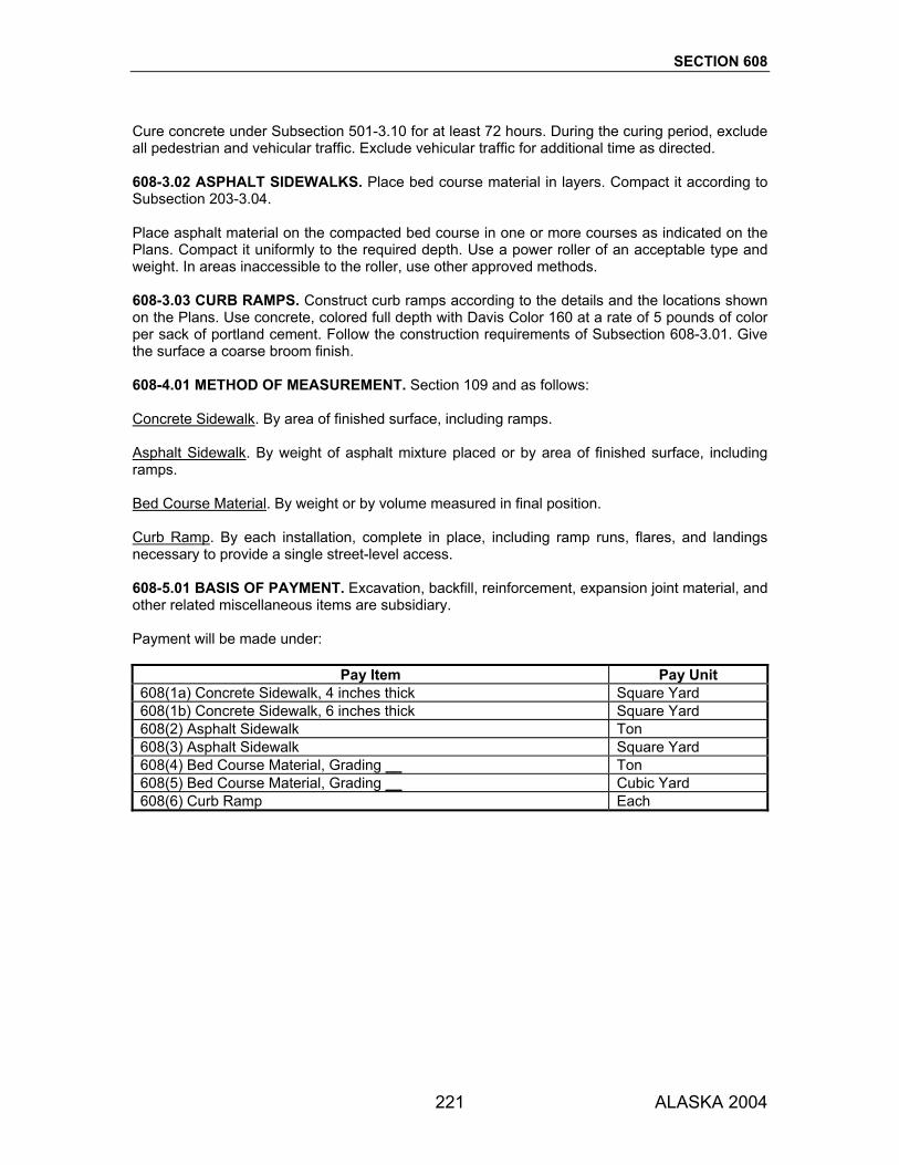
SECTION 608
221 ALASKA 2004
Cure concrete under Subsection 501-3.10 for at least 72 hours. During the curing period, exclude all pedestrian and vehicular traffic. Exclude vehicular traffic for additional time as directed. 608-3.02 ASPHALT SIDEWALKS. Place bed course material in layers. Compact it according to Subsection 203-3.04. Place asphalt material on the compacted bed course in one or more courses as indicated on the Plans. Compact it uniformly to the required depth. Use a power roller of an acceptable type and weight. In areas inaccessible to the roller, use other approved methods. 608-3.03 CURB RAMPS. Construct curb ramps according to the details and the locations shown on the Plans. Use concrete, colored full depth with Davis Color 160 at a rate of 5 pounds of color per sack of portland cement. Follow the construction requirements of Subsection 608-3.01. Give the surface a coarse broom finish. 608-4.01 METHOD OF MEASUREMENT. Section 109 and as follows: Concrete Sidewalk. By area of finished surface, including ramps. Asphalt Sidewalk. By weight of asphalt mixture placed or by area of finished surface, including ramps. Bed Course Material. By weight or by volume measured in final position. Curb Ramp. By each installation, complete in place, including ramp runs, flares, and landings necessary to provide a single street-level access. 608-5.01 BASIS OF PAYMENT. Excavation, backfill, reinforcement, expansion joint material, and other related miscellaneous items are subsidiary. Payment will be made under:
Pay Item Pay Unit 608(1a) Concrete Sidewalk, 4 inches thick Square Yard 608(1b) Concrete Sidewalk, 6 inches thick Square Yard 608(2) Asphalt Sidewalk Ton 608(3) Asphalt Sidewalk Square Yard 608(4) Bed Course Material, Grading __ Ton 608(5) Bed Course Material, Grading __ Cubic Yard 608(6) Curb Ramp Each

222 ALASKA 2004
SECTION 609
CURBING
609-1.01 DESCRIPTION. Construct curb, gutter, or combination curb and gutter. The types of curbing are designated as follows:
Type 1: Cast-in-place concrete curb Type 2: Precast concrete curb Type 3: Asphalt curb
609-2.01 MATERIALS. Use materials that conform to the following:
Concrete, Class A Section 501* Bed Course Material Subsection 703-2.03 Joint Filler Subsection 705-2.01 Joint Sealer Subsection 705-2.02 Joint Mortar Subsection 705-2.04 Precast Concrete Curb Subsection 712-2.04 * Except that in Subsection 501-3.02.3, delete a., b., and c.
Asphalt material for curbing must conform to the following requirements:
Asphalt Cement, PG 52-28 Subsection 702-2.01 Aggregate, Type II or III Subsection 703-2.04
Mix design Requirements (ATM 417): Marshall Stability, lb., min. 1000 Percent Voids, Total Mix 2-5 Compaction, Blows/side 50
CONSTRUCTION REQUIREMENTS 609-3.01 GENERAL. Excavate to the required depth. Compact the base upon which curbs, gutters, and ramps are to be set to a firm, even surface according to Subsection 203-3.04. Make expansion joints in concrete units that comply with the dimensions and spacing shown on the Plans. Fill expansion joints with the type of preformed expansion joint filler specified. Make repairs to concrete units by removing and replacing the entire unit between scoring lines or joints. Clean all discolored concrete. The Engineer will test the finished surface with a 10-foot straightedge. Variations of more than 1/4 inch from the edge of the straightedge to the top or face of the curb or the surface of gutters and ramps, except at grade changes or curves, are unacceptable. 609-3.02 CAST-IN-PLACE CONCRETE CURBING. Use full-depth forms made of wood or metal that are straight, free from warp, and constructed so that they will not interfere with the inspection of grade or alignment. Brace and secure forms to prevent deflection from alignment or grade during concrete placement. Coat forms with an approved form-release agent. Thoroughly moisten the foundation immediately before placing the concrete.

SECTION 609
223 ALASKA 2004
Compact concrete in the forms by vibration or other acceptable methods. Leave forms in place until the concrete sets sufficiently so that the forms can be removed without damaging the concrete. Finish the surface under Subsection 501-3.09.4. Immediately upon removing the forms, rub the exposed face to a uniform surface. Do not plaster the surface. Make weakened plane contraction joints, spaced at 13 feet maximum intervals. Form each joint as a minimum 1/8 inch wide by 1/2 inch deep slot, continuous across the top and down the sides of the section. Make this slot either by sawing or scoring with a tool that will leave the corners rounded. If approved, construct the curb using a curb forming or slip-form machine. Cure concrete under Subsection 501-3.10 for at least 72 hours. During the curing period, exclude all pedestrian and vehicular traffic. Exclude vehicular traffic for additional time as directed. After the concrete sets sufficiently, refill the spaces in front and back of the curb to the required elevation with the specified material and thoroughly compact it. 609-3.03 PRECAST CONCRETE CURB. Set the curb so that the front, top line conforms to the line and grade required. Lay curb with joints 3/8 inch to 1 inch wide. Fill the joints with joint mortar. After the mortar has set, backfill any remaining excavated areas with the specified material and thoroughly compact it. 609-3.04 ASPHALT CURB. When the curb is to be constructed on a cured or aged portland cement concrete base, asphalt pavement, or asphalt treated base, thoroughly sweep and clean the bed using compressed air. Thoroughly dry the surface and, immediately before placing the asphalt mixture, place a tack coat of asphalt material of the approved type and grade onto the surface. Construct asphalt curb using an approved, self-propelled automatic curb machine or a paver with curbing attachments that is heavy enough to compact the curb without riding above the foundation. For short sections or sections with short radii, use other approved means. Make the curb uniform in texture, shape, and density. If painting or sealing is required, curb must be clean, dry, and at ambient temperature. 609-3.05 BACKING CURB. Construct backing curb at curb ramp locations, according to the details and the locations shown on the Plans. 609-4.01 METHOD OF MEASUREMENT. Section 109 and as follows: Curb and Curb and Gutter. Measured along the front face of the curb at the finished grade elevation. No deduction in length will be made for drainage structures or ramps installed in the curb. Backing Curb. Measured along the front face of the curb. Bed Course Material. By weight or by volume measured in final position.

SECTION 609
224 ALASKA 2004
609-5.01 BASIS OF PAYMENT. Payment will be made under:
Pay Item Pay Unit 609(1) Curb, Type __ Linear Foot 609(2) Curb and Gutter, Type __ Linear Foot 609(3) Backing Curb Linear Foot 609(4) Asphalt Curb Linear Foot 609(5) Bed Course Material, Grading __ Ton 609(6) Bed Course Material, Grading __ Cubic Yard

225 ALASKA 2004
SECTION 610
DITCH LINING 610-1.01 DESCRIPTION. Construct ditch lining at the locations on the Plans or as staked. 610-2.01 MATERIALS. Use stones that are sound and durable, are no larger than 8 inches in greatest dimension, and not more than 50% by weight passing a 3-inch sieve as determined by WAQTC FOP for AASHTO T 27/T 11. 610-3.01 CONSTRUCTION REQUIREMENTS. Excavate to the dimensions shown on the Plans. Place and spread ditch lining materials so that the finished face is reasonably uniform and conforms with the lines and slope shown on the Plans or as directed. 610-4.01 METHOD OF MEASUREMENT. Section 109. 610-5.01 BASIS OF PAYMENT. Excavation required below normal ditch grade is subsidiary. Payment will be made under:
Pay Item Pay Unit 610(1) Ditch Lining Cubic Yard 610(2) Ditch Lining Ton 610(3) Ditch Lining Station

226 ALASKA 2004
SECTION 611
RIPRAP 611-1.01 DESCRIPTION. Construct riprap bank and slope protection. 611-2.01 MATERIALS. Evenly graded stones that are hard, angular, and have no more than 50% wear at 500 revolutions as determined by AASHTO T 96. Use stones with breadth and thickness at least 1/4 of its length. Do not use rounded boulders or cobbles on slopes steeper than 2:1. Meet the following gradation for the class specified. Percents are by total weight, weights are for each stone: 1. Class I 0-50% weighing up to 25 pounds 0-10% weighing more than 50 pounds 2. Class II 50-100% weighing 200 pounds or more 0-15% weighing up to 25 pounds 0-10% weighing more than 400 pounds 3. Class III 50-100% weighing 700 pounds or more 0-15% weighing up to 25 pounds 0-10% weighing more than 1400 pounds 4. Class IV 50-100% weighing 2000 pounds or more 0-15% weighing up to 400 pounds 0-10% weighing more than 5400 pounds 611-3.01 CONSTRUCTION REQUIREMENTS. Provide a level, compact area large enough to dump and sort typical loads of riprap at approved location(s). Dump the loads specified in this area and assist the Engineer as needed to sort and measure the stones in the load to determine if the riprap is within specifications. Provide the equipment needed to assist in this sorting. Excavate a footing trench along the toe of the slope as shown on the Plans. Place stones to the thickness, height, and length shown on the Plans, or as staked, in a well-graded mass with a minimum of voids. Fill in unacceptable voids with smaller stones. Place riprap to its full course thickness in one operation. Avoid displacing the underlying material. Do not place riprap in layers or use methods likely to cause segregation. Manipulate the rock sufficiently using a backhoe, rock tongs, or other suitable equipment to secure a reasonably regular surface and stability. 611-4.01 METHOD OF MEASUREMENT. Section 109, by neat line volume or by weight. 611-5.01 BASIS OF PAYMENT. Excavation and backfill are subsidiary. Payment will be made under:
Pay Item Pay Unit 611(1) Riprap, Class __ Cubic Yard 611(2) Riprap, Class __ Ton
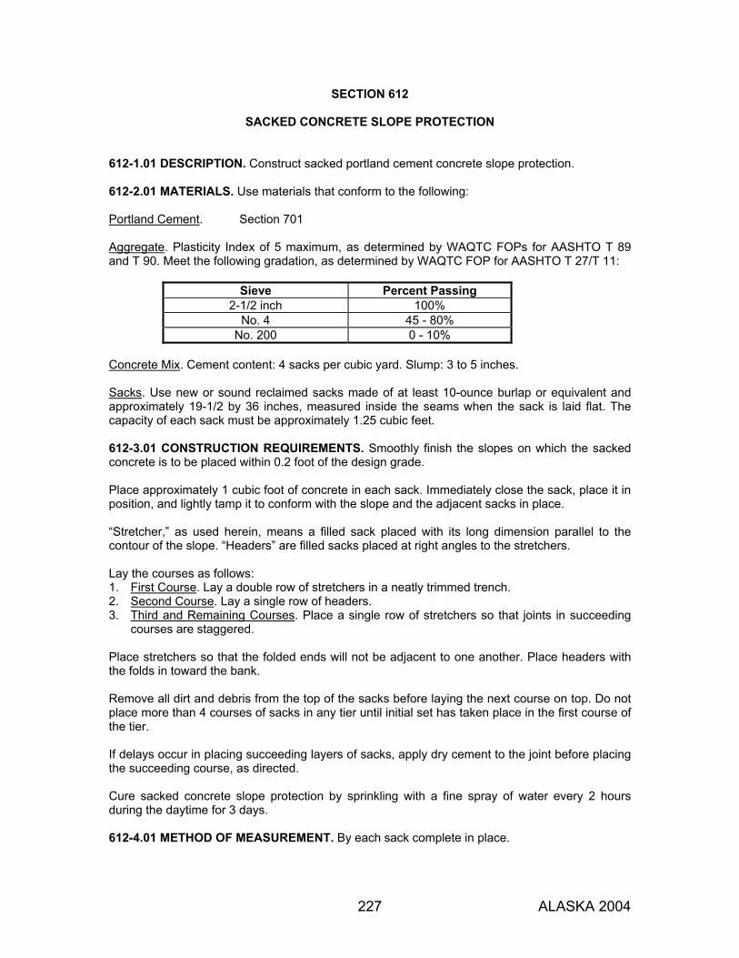
227 ALASKA 2004
SECTION 612
SACKED CONCRETE SLOPE PROTECTION 612-1.01 DESCRIPTION. Construct sacked portland cement concrete slope protection. 612-2.01 MATERIALS. Use materials that conform to the following: Portland Cement. Section 701 Aggregate. Plasticity Index of 5 maximum, as determined by WAQTC FOPs for AASHTO T 89 and T 90. Meet the following gradation, as determined by WAQTC FOP for AASHTO T 27/T 11:
Sieve Percent Passing 2-1/2 inch 100%
No. 4 45 - 80% No. 200 0 - 10%
Concrete Mix. Cement content: 4 sacks per cubic yard. Slump: 3 to 5 inches. Sacks. Use new or sound reclaimed sacks made of at least 10-ounce burlap or equivalent and approximately 19-1/2 by 36 inches, measured inside the seams when the sack is laid flat. The capacity of each sack must be approximately 1.25 cubic feet. 612-3.01 CONSTRUCTION REQUIREMENTS. Smoothly finish the slopes on which the sacked concrete is to be placed within 0.2 foot of the design grade. Place approximately 1 cubic foot of concrete in each sack. Immediately close the sack, place it in position, and lightly tamp it to conform with the slope and the adjacent sacks in place. “Stretcher,” as used herein, means a filled sack placed with its long dimension parallel to the contour of the slope. “Headers” are filled sacks placed at right angles to the stretchers. Lay the courses as follows: 1. First Course. Lay a double row of stretchers in a neatly trimmed trench. 2. Second Course. Lay a single row of headers. 3. Third and Remaining Courses. Place a single row of stretchers so that joints in succeeding
courses are staggered. Place stretchers so that the folded ends will not be adjacent to one another. Place headers with the folds in toward the bank. Remove all dirt and debris from the top of the sacks before laying the next course on top. Do not place more than 4 courses of sacks in any tier until initial set has taken place in the first course of the tier. If delays occur in placing succeeding layers of sacks, apply dry cement to the joint before placing the succeeding course, as directed. Cure sacked concrete slope protection by sprinkling with a fine spray of water every 2 hours during the daytime for 3 days. 612-4.01 METHOD OF MEASUREMENT. By each sack complete in place.

SECTION 612
228 ALASKA 2004
612-5.01 BASIS OF PAYMENT. Excavation and backfill are subsidiary. Payment will be made under:
Pay Item Pay Unit 612(1) Sacked Concrete Slope Protection Each
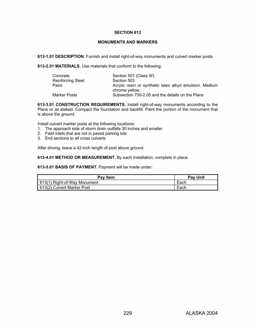
229 ALASKA 2004
SECTION 613
MONUMENTS AND MARKERS 613-1.01 DESCRIPTION. Furnish and install right-of-way monuments and culvert marker posts. 613-2.01 MATERIALS. Use materials that conform to the following:
Concrete Section 501 (Class W) Reinforcing Steel Section 503 Paint Acrylic resin or synthetic latex alkyd emulsion. Medium
chrome yellow. Marker Posts Subsection 730-2.05 and the details on the Plans
613-3.01 CONSTRUCTION REQUIREMENTS. Install right-of-way monuments according to the Plans or as staked. Compact the foundation and backfill. Paint the portion of the monument that is above the ground. Install culvert marker posts at the following locations: 1. The approach side of storm drain outfalls 30 inches and smaller 2. Field inlets that are not in paved parking lots 3. End sections to all cross culverts After driving, leave a 42-inch length of post above ground. 613-4.01 METHOD OR MEASUREMENT. By each installation, complete in place. 613-5.01 BASIS OF PAYMENT. Payment will be made under:
Pay Item Pay Unit 613(1) Right-of-Way Monument Each 613(2) Culvert Marker Post Each

230 ALASKA 2004
SECTION 614
CONCRETE BARRIER
614-1.01 DESCRIPTION. Furnish and install concrete barrier. 614-2.01 MATERIALS. Use materials that conform to the following:
Concrete, Class A Subsection 501-3.01 Reinforcing Steel and Wire Rope Subsection 709-2.01 Reflective Sheeting Material AASHTO M 268, Type III, IV, or V Reflector Assemblies Side-mounted or top-mounted as shown in the Plans.
614-3.01 CONSTRUCTION REQUIREMENTS. Use precast or cast-in-place concrete barrier meeting the lines, dimensions, and requirements shown on the Plans. Give all exposed surfaces a smooth finish. Where the concrete barrier is not placed on pavement, shape, compact, and finish the supporting material to the lines and grades shown on the Plans or as directed. Attach reflector assemblies to concrete barriers according to the manufacturer’s recommendations at 50-foot intervals on the side(s) and top as shown in the Plans. Reflector assemblies are required on both sides of median barriers. 614-4.01 METHOD OF MEASUREMENT. Section 109. 614-5.01 BASIS OF PAYMENT. Reflector assemblies and hardware required to install the barrier are subsidiary. Unless otherwise noted, all material required to widen embankment for concrete barrier as detailed in the Plans and Special Provisions will be measured and paid for under the appropriate pay items shown in the bid schedule. Payment will be made under:
Pay Item Pay Unit 614(1) Concrete Barrier Linear Foot

231 ALASKA 2004
SECTION 615
STANDARD SIGNS
615-1.01 DESCRIPTION. Furnish and install standard signs and delineators. Remove and relocate or remove and dispose of existing signs and markers, as specified. 615-2.01 MATERIALS. Use materials that conform to the following Subsections:
Sheet Aluminum 730-2.01 High Density Overlaid Plywood 730-2.02 Reflective Sheeting 730-2.03 Sign Posts 730-2.04 Delineator Posts 730-2.05 Acrylic Prismatic Reflectors 730-2.06
1. Shop Drawings. Submit shop drawings, for all signs that must meet the ASDS letter width
and spacing charts, for approval before fabrication. Submit 4 sets of collated shop drawings prepared according to Subsection 105-1.02. Show the following on each sign drawing: a. Dimensions of all horizontal and vertical characters and spaces b. Overall dimensions c. Sign material and sheeting material type d. Panel thickness e. Legend and letter series f. Whether the sign will be framed
2. Sign Fabrication. Use Type III reflective sheeting (for lettering, symbols, borders, and
background) on sheet aluminum panels for all signs except the following: a. Orange Background Signs: Use either Type II or Type III reflective sheeting on sheet
aluminum, plastic, or plywood panels. Use sheet aluminum if the sign is for permanent installation.
b. Railroad Crossbucks and Vertical Crossbuck Support Panels: Use 3M "Dimond Grade VIP", Stimsonite 6200, or approved equal.
c. Non-Illuminated Overhead Signs: Use 3M "Dimond Grade VIP", Stimsonite 6200, or approved equal on sheet aluminum panels.
Use a manufacturer-recommended clear coat on all screened signs. Use sign layouts (including characters, symbols, corner radii, and borders) that conform to the ASDS. Frame all rectangular signs over 53 inches (measured along the horizontal axis) and all diamond shape signs 60 x 60 inches and larger. Construct the frames of aluminum as indicated on the Plans.
3. Sign Posts and Bases. Use sign posts and bases of the types specified. The structural
aspects of design and materials for sign supports must comply with the AASHTO Standard Specifications for Structural Supports for Highway Signs, Luminaires, and Traffic Signals. Do not splice sign posts.
Use Class A concrete for steel-reinforced slip base and breakaway base foundations meeting the requirements of Section 501. Concrete for other sign foundations may be Class W.
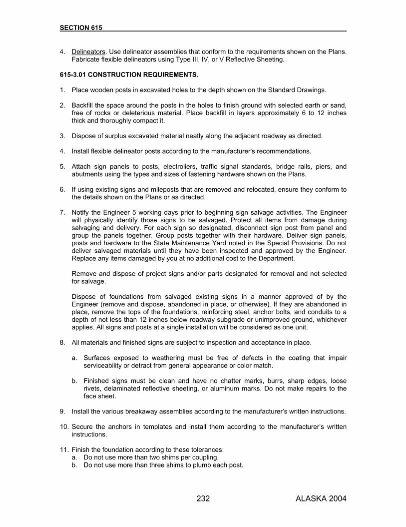
SECTION 615
232 ALASKA 2004
4. Delineators. Use delineator assemblies that conform to the requirements shown on the Plans. Fabricate flexible delineators using Type III, IV, or V Reflective Sheeting.
615-3.01 CONSTRUCTION REQUIREMENTS. 1. Place wooden posts in excavated holes to the depth shown on the Standard Drawings. 2. Backfill the space around the posts in the holes to finish ground with selected earth or sand,
free of rocks or deleterious material. Place backfill in layers approximately 6 to 12 inches thick and thoroughly compact it.
3. Dispose of surplus excavated material neatly along the adjacent roadway as directed. 4. Install flexible delineator posts according to the manufacturer's recommendations. 5. Attach sign panels to posts, electroliers, traffic signal standards, bridge rails, piers, and
abutments using the types and sizes of fastening hardware shown on the Plans. 6. If using existing signs and mileposts that are removed and relocated, ensure they conform to
the details shown on the Plans or as directed. 7. Notify the Engineer 5 working days prior to beginning sign salvage activities. The Engineer
will physically identify those signs to be salvaged. Protect all items from damage during salvaging and delivery. For each sign so designated, disconnect sign post from panel and group the panels together. Group posts together with their hardware. Deliver sign panels, posts and hardware to the State Maintenance Yard noted in the Special Provisions. Do not deliver salvaged materials until they have been inspected and approved by the Engineer. Replace any items damaged by you at no additional cost to the Department.
Remove and dispose of project signs and/or parts designated for removal and not selected for salvage.
Dispose of foundations from salvaged existing signs in a manner approved of by the Engineer (remove and dispose, abandoned in place, or otherwise). If they are abandoned in place, remove the tops of the foundations, reinforcing steel, anchor bolts, and conduits to a depth of not less than 12 inches below roadway subgrade or unimproved ground, whichever applies. All signs and posts at a single installation will be considered as one unit.
8. All materials and finished signs are subject to inspection and acceptance in place.
a. Surfaces exposed to weathering must be free of defects in the coating that impair serviceability or detract from general appearance or color match.
b. Finished signs must be clean and have no chatter marks, burrs, sharp edges, loose rivets, delaminated reflective sheeting, or aluminum marks. Do not make repairs to the face sheet.
9. Install the various breakaway assemblies according to the manufacturer’s written instructions. 10. Secure the anchors in templates and install them according to the manufacturer’s written
instructions. 11. Finish the foundation according to these tolerances:
a. Do not use more than two shims per coupling. b. Do not use more than three shims to plumb each post.

SECTION 615
233 ALASKA 2004
12. Remove and replace all foundations requiring more than three shims to plumb a post without extra compensation.
13. Construct the top of any foundation located on a slope so that the finished slope passes
through the top center of the foundation. Grade the area 24 inches up and down slope of the foundation edge so that no portion of the foundation projects above the surrounding slope and water will drain away from the foundation.
14. Attach a label to the back of all standard signs in the lower right corner. Make the label at
least 15 square inches and show the year the sign was purchased from the manufacturer. Show the last two digits of the year in clear and bold numbers. Make the label from Type I or brighter reflective sheeting. Use background and legend colors meeting Table 615-1.
TABLE 615-1 DECAL COLORS
YEAR BACKGROUND COLOR LEGEND COLOR XXX1 Yellow Black XXX2 Red White XXX3 Blue White XXX4 Green White XXX5 Brown White XXX6 Orange Black XXX7 Black White XXX8 White Black XXX9 Purple White XXX0 Strong Yellow-Green Black
Central values and tolerance limits for each color, as referenced in the MUTCD, are available from the Federal Highway Administration, (HHS-30), 400 7th St. SW, Washington, D.C. 20590
615-3.02 SIGN PLACEMENT AND INSTALLATION. The location and type of installation will be as shown on the Plans. Sign locations are approximate and subject to field adjustment by the Engineer. Do not allow the top of the embedded steel tube to extend more than 2 inches above the surrounding ground and concrete foundation. On all signs, install 2-inch diameter wind washers, colored to match the sign face, between the fastener head and the sign. Use rust-resistant washers fabricated from a material equal in strength to the sign blank. Mount signs on mast arms level. Bring existing signs that are to remain, into conformance with Standard Drawing S-05. Keep existing signs in service until they are no longer needed.
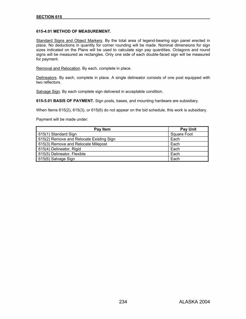
SECTION 615
234 ALASKA 2004
615-4.01 METHOD OF MEASUREMENT. Standard Signs and Object Markers. By the total area of legend-bearing sign panel erected in place. No deductions in quantity for corner rounding will be made. Nominal dimensions for sign sizes indicated on the Plans will be used to calculate sign pay quantities. Octagons and round signs will be measured as rectangles. Only one side of each double-faced sign will be measured for payment. Removal and Relocation. By each, complete in place. Delineators. By each, complete in place. A single delineator consists of one post equipped with two reflectors. Salvage Sign. By each complete sign delivered in acceptable condition. 615-5.01 BASIS OF PAYMENT. Sign posts, bases, and mounting hardware are subsidiary. When Items 615(2), 615(3), or 615(6) do not appear on the bid schedule, this work is subsidiary. Payment will be made under:
Pay Item Pay Unit 615(1) Standard Sign Square Foot 615(2) Remove and Relocate Existing Sign Each 615(3) Remove and Relocate Milepost Each 615(4) Delineator, Rigid Each 615(5) Delineator, Flexible Each 615(6) Salvage Sign Each

235 ALASKA 2004
SECTION 616
THAW PIPE AND THAW WIRES 616-1.01 DESCRIPTION. Furnish, fabricate, and install thaw pipes or electric thaw wire.
MATERIALS 616-2.01 THAW PIPE. Use materials that conform to the following:
Pipe and Fittings ASTM A 53, galvanized per AASHTO M 111 Pipe Hangers ASTM A 47, galvanized per AASHTO M 111 Braces for Standpipe ASTM A 36, galvanized per AASHTO M 111 Bolts and Nuts ASTM A 307, galvanized per AASHTO M 232
616-2.02 THAW WIRE. Provide materials, devices, fittings, and hardware meeting NEMA standards and bearing the approval of a third party certification, meeting ANSI Z 34.1. Deliver all warranties and guarantees provided by the manufacturer to the Engineer before acceptance of this work. 1. Conduit and Fittings.
a. Use conduit, couplings, elbows, and nipples that are rigid, hot-dip galvanized steel meeting ANSI C80.1. Install them as indicated on the applicable drawings. Use threaded type couplings, elbows, and nipples.
b. Use fittings and miscellaneous conduit hardware that are vapor-proof, galvanized cast
iron or steel meeting ANSI/NEMA FB-1 and are compatible with the rigid conduit furnished and installed. Use threaded type fittings.
2. Heat Cable.
a. Use heat cable that meets the following standards: (1) Parallel-circuit, 120 or 240 VAC, 16 AWG minimum copper bus wire, with self-limiting
conductive core
(2) Modified polyolefin inner jacket, tinned copper or nickel-clad metallic braid, and fluoropolymer overjacket
(3) Rated in conduit at 8 W/ft. at 50 °F
(4) UL Listed or FM approved specifically as a culvert deicing system in conduit
b. Use connection components that are rated at NEMA 4X. Use power connections and
seals specifically designed for use with the particular type and size of heat cable. 3. Controls.
a. Use a thermostat that is heavy duty, single stage, line voltage type. Operating temperature range: 25 to +125 °F. Provide with NEMA 1 enclosure and capillary bulb for remote sensing.

SECTION 616
236 ALASKA 2004
b. Use a contactor that is electrically held, 30 amp rated, lighting type, with NEMA 1 enclosure.
c. Use a switch that is heavy duty hand-off-auto type with a gloved hand selector switch
knob and NEMA 1 enclosure. 4. Conductors. Use copper conductors with insulation rated for 300 volt minimum where the
impressed voltage is 100 volts or less and 600 volt where the impressed voltage is between 100 and 600 volts.
a. Service and Feeder Cables. Use No. 8 AWG, or larger, with type USE, THWN, THHN, or
XHHW insulation. b. Underground Wire. Use No. 6 AWG with type XHHW or USE insulation where buried in
conduit. c. Branch Circuit Wire. Use No. 12 AWG with type USE or XHHW insulation. d. Control Wire. Use No. 16 AWG with stranded conductor with type SIS insulation within
control panels. e. Splices for Copper Conductors. Use solderless, preinsulated, compression set type only
with heat-shrink tubing jacket. When making splices between power leads and heat cable cold leads, use splicing kits designed specifically for that purpose.
f. Terminations. Use compression set or bolted type.
5. Device, Junction, and Pull Boxes.
a. Boxes Installed Above Grade. Use boxes that are hot dipped galvanized cast iron or corrosion resistant alloy complete with conduit hubs. Use boxes designed for damp or wet locations.
b. Boxes Installed Below Grade (exposed to earth). Use concrete boxes as required or
shown in the drawings. Provide covers constructed of ribbed cast metal alloy. c. Cast Thermoplastic or Fiberglass Boxes. Use where indicated in the drawings.
6. Receptacles, Remote Power. Use remote power receptacles that are 2-pole, 3-wire
grounding, male, 30 amp, 120 or 240 VAC, NEMA L6-30. 7. Circuit Breakers.
a. Provide 1- or 2-pole circuit breakers as scheduled in the drawings. Multiple breakers must operate all poles simultaneously. Use circuit breakers that operate manually for normal ON-OFF switching and automatically for overload and short-circuit conditions. Ensure that the operating mechanism will not prevent trip action when held in the ON position. Provide 10,000-ampere symmetrical interrupting capacity minimum. Provide bolt-in type with a molded case.
b. Use Ground Fault Interrupter (GFI) circuit breakers that sense ground fault current, that
trip at 30±1 milliamperes within 2 cycles, and that have the following: (1) Internal circuitry to prevent nuisance tripping caused by voltage spikes, radio
frequency interference, and electromagnetic interference.
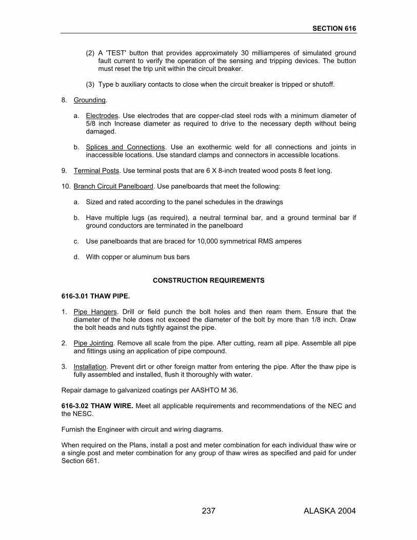
SECTION 616
237 ALASKA 2004
(2) A 'TEST' button that provides approximately 30 milliamperes of simulated ground fault current to verify the operation of the sensing and tripping devices. The button must reset the trip unit within the circuit breaker.
(3) Type b auxiliary contacts to close when the circuit breaker is tripped or shutoff.
8. Grounding.
a. Electrodes. Use electrodes that are copper-clad steel rods with a minimum diameter of 5/8 inch Increase diameter as required to drive to the necessary depth without being damaged.
b. Splices and Connections. Use an exothermic weld for all connections and joints in
inaccessible locations. Use standard clamps and connectors in accessible locations. 9. Terminal Posts. Use terminal posts that are 6 X 8-inch treated wood posts 8 feet long. 10. Branch Circuit Panelboard. Use panelboards that meet the following:
a. Sized and rated according to the panel schedules in the drawings
b. Have multiple lugs (as required), a neutral terminal bar, and a ground terminal bar if ground conductors are terminated in the panelboard
c. Use panelboards that are braced for 10,000 symmetrical RMS amperes
d. With copper or aluminum bus bars
CONSTRUCTION REQUIREMENTS 616-3.01 THAW PIPE. 1. Pipe Hangers. Drill or field punch the bolt holes and then ream them. Ensure that the
diameter of the hole does not exceed the diameter of the bolt by more than 1/8 inch. Draw the bolt heads and nuts tightly against the pipe.
2. Pipe Jointing. Remove all scale from the pipe. After cutting, ream all pipe. Assemble all pipe
and fittings using an application of pipe compound. 3. Installation. Prevent dirt or other foreign matter from entering the pipe. After the thaw pipe is
fully assembled and installed, flush it thoroughly with water. Repair damage to galvanized coatings per AASHTO M 36. 616-3.02 THAW WIRE. Meet all applicable requirements and recommendations of the NEC and the NESC. Furnish the Engineer with circuit and wiring diagrams. When required on the Plans, install a post and meter combination for each individual thaw wire or a single post and meter combination for any group of thaw wires as specified and paid for under Section 661.
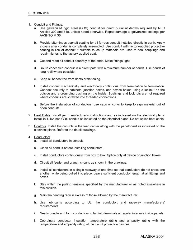
SECTION 616
238 ALASKA 2004
1. Conduit and Fittings. a. Use galvanized rigid steel (GRS) conduit for direct burial at depths required by NEC
Articles 300 and 710, unless noted otherwise. Repair damage to galvanized coatings per AASHTO M 36.
b. Provide bituminous asphalt coating for all ferrous conduit installed directly in earth. Apply
2 coats after conduit is completely assembled. Use conduit with factory-applied protective coating in lieu of asphalt if suitable touch-up materials are used to seal couplings and repair injuries to the factory-applied coat.
c. Cut and ream all conduit squarely at the ends. Make fittings tight. d. Route concealed conduit in a direct path with a minimum number of bends. Use bends of
long radii where possible. e. Keep all bends free from dents or flattening. f. Install conduit mechanically and electrically continuous from termination to termination.
Connect securely to cabinets, junction boxes, and device boxes using a locknut on the outside and a grounding bushing on the inside. Bushings and locknuts are not required where conduits are screwed into threaded connections.
g. Before the installation of conductors, use caps or corks to keep foreign material out of
open conduits. 2. Heat Cable. Install per manufacturer’s instructions and as indicated on the electrical plans.
Install in 1-1/2 inch GRS conduit as indicated on the electrical plans. Do not splice heat cable. 3. Controls. Install the controls in the load center along with the panelboard as indicated on the
electrical plans. Refer to the detail drawings. 4. Conductors.
a. Install all conductors in conduit. b. Clean all conduit before installing conductors. c. Install conductors continuously from box to box. Splice only at device or junction boxes. d. Circuit all feeder and branch circuits as shown in the drawings. e. Install all conductors in a single raceway at one time so that conductors do not cross one
another while being pulled into place. Leave sufficient conductor length at all fittings and boxes.
f. Stay within the pulling tensions specified by the manufacturer or as noted elsewhere in
this division. g. Maintain bending radii in excess of those allowed by the manufacturer. h. Use lubricants according to UL, the conductor, and raceway manufacturers’
requirements. i. Neatly bundle and form conductors to fan into terminals at regular intervals inside panels. j. Coordinate conductor insulation temperature rating and ampacity rating with the
temperature and ampacity rating of the circuit protection devices.
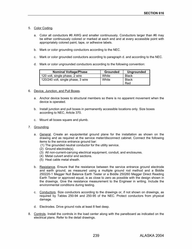
SECTION 616
239 ALASKA 2004
5. Color Coding.
a. Color all conductors #6 AWG and smaller continuously. Conductors larger than #6 may be either continuously colored or marked at each end and at every accessible point with appropriately colored paint, tape, or adhesive labels.
b. Mark or color grounding conductors according to the NEC. c. Mark or color grounded conductors according to paragraph d. and according to the NEC. d. Mark or color ungrounded conductors according to the following convention:
Nominal Voltage/Phase Grounded Ungrounded
120 volt, single phase, 2 wire White Black 120/240 volt, single phase, 3 wire White Black Red
6. Device, Junction, and Pull Boxes.
a. Anchor device boxes to structural members so there is no apparent movement when the device is operated.
b. Install junction and pull boxes in permanently accessible locations only. Size boxes
according to NEC, Article 370. c. Mount all boxes square and plumb.
7. Grounding.
a. General. Create an equipotential ground plane for the installation as shown on the drawing and as required at the service meter/disconnect cabinet. Connect the following items to the service entrance ground bar: (1) The grounded neutral conductor for the utility service. (2) Ground electrode(s). (3) All non-current-carrying electrical equipment, conduit, and enclosures. (4) Metal culvert and/or end sections. (5) Heat cable metal sheath.
b. Resistance. Ensure that the resistance between the service entrance ground electrode
and earth ground, as measured using a multiple ground rod method and a Biddle 250220-1 Megger Null Balance Earth Tester or a Biddle 250260 Megger Direct Reading Earth Tester or approved equal, is as close to zero as possible with the design shown in the drawings. Give the resistance measurement to the Engineer in writing. Include the environmental conditions during testing.
c. Conductors. Size conductors according to the drawings or, if not shown on drawings, as
required by Tables 250-94 and 250-95 of the NEC. Protect conductors from physical damage.
d. Electrodes. Drive ground rods at least 8 feet deep. 8. Controls. Install the controls in the load center along with the panelboard as indicated on the
electrical plans. Refer to the detail drawings.

SECTION 616
240 ALASKA 2004
9. Branch Circuit Panelboard.
a. Mounting. Mount panelboard interiors inside load center cabinet after the enclosure has been installed as shown on the Plans and as described under Section 661.
b. Circuit Breakers. Install circuit breakers in the order specified in the drawing panelboard
schedules. Type the circuit directory with circuit descriptions as they are shown in the drawing panelboard schedules. Make the directory configuration identical to the circuit breaker configuration.
616-4.01 METHOD OF MEASUREMENT. Section 109 and as follows: Thaw Pipe. By the length, measured along the line and grade of the thaw pipe, complete in place, or by each complete unit. Thaw Wire. By the measured length of the heated sections complete in place, or by each complete unit. 616-5.01 BASIS OF PAYMENT. All fittings, including standpipes, are subsidiary. Payment will be made under:
Pay Item Pay Unit 616(1) __ Inch Diameter Thaw Pipe Linear Foot 616(2 __ Inch Diameter Thaw Pipe Each 616(3) Thaw Wire Installation Linear Foot 616(4) Thaw Wire Installation Each
241 ALASKA 2004
SECTION 617
RAILROAD CROSSINGS 617-1.01 DESCRIPTION. Construct railroad grade crossings and foundations for automatic signal equipment. 617-1.02 DEFINITIONS. 1. Railroad. The corporation or agency responsible for managing and operating the railroad. 2. Chief Engineer. The Railroad’s Chief Engineer. 617-2.01 MATERIALS. Use materials that conform to the kind, grade, type, and size specified on the Plans or listed below:
Anchor Bolts ASTM A 307. Galvanize per AASHTO M 232, Class A Rigid Metal Conduit, UL Standard UL-6, ANSI Standard C 80.1, hot-dip Couplings, and Fittings galvanized Concrete Section 501 (Class A) Railroad Crossing Pads Rubber or high density polyethylene as manufactured by
the Goodyear Tire and Rubber Co., St. Mary's, Ohio; Railroad Friction Products Corp., Wilmerding, Pennsylvania 15148; Red Hawk Rubber Company, Inc., 3911 Dayton Street, McHenry, Illinois 60050; Omni Rubber Products, Inc., P.O. Box 2788, Portland, Oregon 97208-2788; or an approved equal
Repair damage to galvanized coatings according to AASHTO M 36. 617-3.01 CONSTRUCTION REQUIREMENTS. 1. General.
a. Conduct all work on the railroad crossing in strict accordance with the rules and regulations governing the railroad and according to Subsection 107-1.08.
b. Remove the track from service only at the times authorized by the Chief Engineer.
Restore the track to service within the time period specified. Should the embankment construction not be completed on time, liquidated damages will be charged at the rate specified in the written authorization allowing the excavation or at the rate specified in Paragraph 6, Train Delays, Subsection 107-1.08 of the Special Provisions, whichever is greater. The Department will collect the amount of liquidated damages from the Contractor and pay them to the Railroad.
c. The Railroad will accomplish all track work involving, but not limited to, removing and
replacing ties, rails, and appurtenances. The Department will pay for all costs for this work.
d. The Railroad will furnish and install conduit runs from junction boxes to railroad signal
bases only, except advance flasher bases. The Railroad will furnish and install all wire,

SECTION 617
242 ALASKA 2004
signal equipment, and all other work and materials necessary to obtain a complete and operational system. The Department will pay all costs for this work.
2. Railroad Signal and Relay Case Foundation.
a. Perform foundation work for automatic signal equipment, according to the applicable sections of these Specifications.
b. After completing each signal foundation, install a protective cap securely over the
foundation to protect the conduit end and anchor bolt threads. Fabricate the protective cap using wood, galvanized sheet metal, or other approved material.
3. Electrical Conduit.
a. Trench Excavation. Excavate trenches to the depth shown on the Plans and the necessary width for proper placement of conduit. Make the sidewalls of the trenches as vertical as practicable. Grade the bottom of the trenches accurately to provide a uniform bearing and support for the conduit along its entire length. Remove material unsuitable for bedding, to 6 inches below the bedding surface. Replace with suitable material and compact it according to Subsection 203-3.04.
b. Placing Conduit.
(1) Lay conduit on a firm foundation in the trench without damage to the coating.
(2) Ream the ends of all conduits, whether shop or field cut, to remove burrs and rough
edges. Make cuts square and true so that the ends will butt or come together for their full circumference. Do not use slip joints or running threads for coupling conduit. When you cannot use a standard coupling, use an approved threaded union coupling. Paint the threads on all conduit with a rust preventative paint before couplings and fittings are made up. Draw all couplings tight until the ends of the conduits are brought together, providing a good electrical connection throughout the entire length of the conduit run.
(3) Repair any damage to conduit coating with a rust preventative paint. Cap all conduit
ends.
(4) Install a No. 12 AWG galvanized pull wire in all conduits. Double back at least 2 feet of pull wire into the conduit at each termination.
(5) Install all electrical conduit to conform to the NEC.
c. Backfilling. Do not backfill the trenches until conduit placement is approved. Backfill the
trenches carefully with the excavated materials approved for backfilling consisting of earth, loam, sandy clay, sand and gravel, soft shale, or other approved materials. Use materials that are free from large clods of earth, large stones, roots, and sticks. Place the backfill material in 6-inch layers and compact it thoroughly and carefully for the entire depth of the trench. Use extreme care when backfilling the bottom 12 inches of the trench to prevent injury or damage to the conduit. Compact backfill according to Subsection 203-3.04.
4. Railroad Crossing. Confine work to the construction limits of each crossing. Railroad crossing
construction consists of removing the existing crossing surface, excavating to the depth shown on the Plans, furnishing and installing geotextile material, furnishing and backfilling with railroad ballast to the original elevation, and furnishing and installing new railroad crossing pads. Furnish and install detours as required.
SECTION 617
243 ALASKA 2004
The Railroad is responsible to remove the existing track material before excavation, raise the grade when called for on the Plans, and furnish and install new track material at their expense. The Railroad will raise the grade in 3- to 4-inch lifts. Provide a front end loader for use by the Railroad to lift out the existing track assembly. Coordinate the crossing construction and the grade raise through the Chief Engineer. After each lift of the grade raise, furnish and install a wood plank crossing, grade the approaches to the crossing, and temporarily open the roadway to traffic. Remove the wood planks before each lift of the grade raise. The type of planking material required will be specified in the Plans. After completing the grade raise and before final surfacing of the crossing, allow a minimum of 3 days’ rail traffic over the crossing. During this time, furnish and install a wood plank crossing, grade the approaches, and open the crossing to vehicular traffic. The Railroad will huckbolt the rail joints after final surfacing. Install the Railroad crossing pads according to the manufacturer’s recommendations.
617-4.01 METHOD OF MEASUREMENT. Section 109 and as follows: Cantilever Signal Foundations, Railroad Furnished Signal Bases, Type IA and Type II Junction Boxes, and Railroad Signal Load Centers. Per each, complete in place and accepted. Rigid Metal Conduit with pull wire. By the linear foot installed in place and accepted. The measurement will be straight line from the center of one junction box or foundation to the center of another junction box or foundation. 617-5.01 BASIS OF PAYMENT. Lump sum items include all excavation and backfill required. Payment will be made under:
Pay Item Pay Unit 617(1) Railroad Crossing Lump Sum 617(2) Railroad Signal and Relay Case Foundations Lump Sum 617(3) Cantilever Signal Foundation Each 617(4) Railroad Furnished Signal Base Each 617(5) Rigid Metal Conduit with pull wire Linear Foot 617(6) Type IA Junction Box Each 617(7) Type II Junction Box Each 617(8) Railroad Signal Load Center Each

244 ALASKA 2004
SECTION 618
SEEDING 618-1.01 DESCRIPTION. Establish a perennial stand of grass or other specified living vegetative cover, by seeding, in the areas indicated on the Plans. Maintain the cover for the term of the Contract. 618-2.01 MATERIALS. Use materials that conform to the Special Provisions and the following:
Seed Section 724 Fertilizer (20-20-10) Section 725 Water Subsection 712-2.01
CONSTRUCTION REQUIREMENTS 618-3.01 SOIL PREPARATION. Clear all areas to be seeded of stones 4 inches in diameter and larger and of all weeds, plant growth, sticks, stumps, and other debris or irregularities that might interfere with the seeding operation, growth of grass, or subsequent maintenance of the grass-covered areas. Make areas to be seeded reasonably free of ruts, holes, and humps. When specified, apply topsoil according to Section 620. Roughen the surface slightly by means of dozer-tracking or other approved method. 618-3.02 SEEDING SEASONS. Seed and fertilize during the local growing season. Do not seed during windy conditions or when climatic conditions or ground conditions would hinder placement or proper growth. 618-3.03 APPLICATION. Apply seed mix at the rate specified in the Special Provisions. Apply fertilizer at the rate of 400-450 pounds per acre. Apply mulch at the rate specified in the Special Provisions. Use any of the following methods: 1. Hydraulic Method.
a. Furnish and place a slurry made of seed, fertilizer, water, and other components as required by the Special Provisions.
b. Use hydraulic seeding equipment that will maintain a continuous agitation and apply a
homogeneous mixture through a spray nozzle. The pump must produce enough pressure to maintain a continuous, nonfluctuating spray that will reach the extremities of the seeding area with the pump unit located on the roadbed. Provide enough hose to reach areas not practical to seed from the nozzle unit situated on the roadbed.
c. If mulch material is required, it may be added to the water slurry in the hydraulic seeder
after adding the proportionate amounts of seed and fertilizer. Add seed to the slurry mixture no more than 30 minutes before application.

SECTION 618
245 ALASKA 2004
d. Mix the slurry and apply it evenly.
2. Dry Methods.
a. Use mechanical spreaders, seed drills, landscape seeders, aircraft, cultipacker seeders, fertilizer spreaders, or other approved mechanical spreading equipment when seed and fertilizer are to be applied in dry form.
b. Spread fertilizer separately at the specified rate.
618-3.04 PLANT ESTABLISHMENT AND MAINTENANCE. Protect seeded areas against traffic and erosion. Promptly repair surfaces that are gullied or otherwise damaged following seeding by regrading, reseeding, and remulching as needed. Water and maintain seeded areas in a satisfactory condition until final inspection and acceptance of the work. Use equipment that can water all seeded areas without damaging the seed bed. Reseed any areas not showing evidence of satisfactory growth within 3 weeks of seeding. 618-4.01 METHOD OF MEASUREMENT. Section 109 and as follows: Seeding by the Acre. By the area of ground surface acceptably seeded and maintained. Seeding by the Pound. By the weight of seed acceptably placed. Water for Seeding. If weighed, a conversion factor of 8.34 pounds per gallon will be used to convert weights to gallons. 618-5.01 BASIS OF PAYMENT. Mulching will be paid for under Section 619. Seeding by the Acre. Seed, water, and fertilizer are subsidiary. Seeding by the Pound. Additional work required will be measured separately. Payment will be made under:
Pay Item Pay Unit 618(1) Seeding Acre 618(2) Seeding Pound 618(3) Water for Seeding M Gal.
246 ALASKA 2004
SECTION 619
SOIL STABILIZATION 619-1.01 DESCRIPTION. Furnish, place, and maintain mulch or matting material where shown on the Plans. 619-2.01 MATERIALS. Use materials that conform to the following:
Mulch Subsection 727-2.01 Matting Subsection 727-2.02 Staples Subsection 727-2.03
CONSTRUCTION REQUIREMENTS 619-3.01 SURFACE PREPARATION. Smooth the surface and backfill all gullies and potholes before application. Remove all sticks and other foreign material that prevent contact of the mulch or matting and surface. Ensure that the surface is moist at the time of placement. 619-3.02 APPLICATION. Apply mulch material at the rate specified in the Special Provisions. If seeding is specified, complete the application of mulch or matting within 24 hours after seed is placed. Staple matting every 5 feet at joints and edges or as recommended by the manufacturer. Do not use vehicles or equipment which cause rutting or displacement of the subgrade or topsoil. 619-3.03 MAINTENANCE. Reshape and reseed any damaged areas and repair the mulch or matting as required. Maintain the mulch or matting until all work on the project is complete and accepted. 619-4.01 METHOD OF MEASUREMENT. Section 109, measured on the slope of the ground surface. 619-5.01 BASIS OF PAYMENT. Water, maintenance, and repair are subsidiary. Payment will be made under:
Pay Item Pay Unit 619(1) Mulching Square Yard 619(2) Matting Square Yard
247 ALASKA 2004
SECTION 620
TOPSOIL 620-1.01 DESCRIPTION. Furnish and spread topsoil where shown on the Plans. 620-2.01 MATERIALS. Use materials that conform to the following:
Topsoil Section 726 620-3.01 PLACING. Spread the topsoil evenly on the designated areas to the depth (after settlement) shown on the Plans. Do not place when the ground or topsoil is frozen, excessively wet, or in a condition detrimental to the work. Keep the roadway surfaces clean of topsoil during hauling and spreading operations. 620-3.02 MAINTENANCE AND REPAIR. Maintain the areas covered by topsoil until subsequent seeding or landscaping is accomplished. Complete any repairs or topsoil replacement, including damage or loss resulting from winter shutdown, without extra compensation. 620-4.01 METHOD OF MEASUREMENT. Section 109, measured on the slope of the ground surface. 620-5.01 BASIS OF PAYMENT. Stockpiling and rehandling of topsoil during the stripping operations or during placement are subsidiary. Topsoil repair, maintenance, and replacement are subsidiary. Payment will be made under:
Pay Item Pay Unit 620(1) Topsoil Square Yard

248 ALASKA 2004
SECTION 621
PLANTING TREES AND SHRUBS 621-1.01 DESCRIPTION. Furnish, plant or transplant, and maintain trees, shrubs, and other plants on prepared areas in conformance with the Plans.
MATERIALS 621-2.01 PLANT STOCK. Use plants that are true to type and name according to the current edition of Standardized Plant Names, American Joint Committee on Horticultural Nomenclature. Label each bundle, or each plant if not bundled, with scientific name and size. Use the variety and species specified in the Special Provisions. Use plants that are typical of the species or variety and that conform to ANSI-Z 60.1 of the American Nursery and Landscape Association of (ANLA) for type and grade. Use plants free from disease, injurious insects, mechanical wounds, broken branches, decay, or other defects. 1. Nursery Stock.
a. Use trees and shrubs furnished from a nursery that have been root pruned during their growing period in the nursery according to standard nursery practice to produce a fibrous compact root system suitable for the various species and sizes called for on the Plans. Use nursery stock that has been growing for at least 2 full growing seasons.
b. Use container grown plants that have been growing for at least 1 year but no more than 2
years in the same container. Only ground cover plants may exhibit a “pot-bound” condition.
2. Collected Stock. Follow ANLA Handbook collection procedures. Collect healthy plants
growing under natural conditions in soils and in locations which lend themselves to proper collecting practices. Ensure that the root systems or balls for collected stock is at least 25% larger than those specified for nursery-grown material.
3. Balled and Burlapped Plants.
a. Meet the ball diameters and depths specified in the American Standard for Nursery Stock of the ANLA.
b. Furnish plants with a firm ball of earth from the original and undisturbed soil in which the
plant was growing. Wrap the ball with burlap or similar approved material and lace it tightly to hold the ball firm and intact. Plant material that arrives at the planting site with broken or loose balls or with manufactured earth, are unacceptable.
4. Substitutions. No substitutions are permitted without written approval. 5. Storage and Packing. Handle and pack all plant material according to good nursery practices
as required by soil and climatic conditions. Plants that show signs of improper storage or handling are unacceptable.
6. Inspection.
a. Make all planting stock available for inspection in the nursery or collecting field before it is dug. At least 10 working days before digging operations, furnish complete and detailed information about the supply source for each item of plant materials.
SECTION 621
249 ALASKA 2004
b. Final inspection and acceptance for size of ball or roots, color, absence of defects, and
for other requirements will be made at the planting site before placing the plants in their permanent positions.
621-2.02 FERTILIZER. Use fertilizer that meets Section 725. Meet the chemical proportions specified in the Special Provisions. 621-2.03 LIMESTONE. Use limestone that meets Subsection 712-2.03. 621-2.04 MULCH. Use mulch that meets Section 727. 621-2.05 BACKFILL MIX. Use backfill mix that meets Section 726. 621-2.06 STAKES. Use stakes that are strong and fit for the purpose intended. 621-2.07 TREE WOUND DRESSING. Use tree wound dressing that is antiseptic, waterproof, and contains no materials harmful to the living tissue of trees.
CONSTRUCTION REQUIREMENTS 621-3.01 TEMPORARY STORAGE. Where temporary storage or heeling-in of plants is required, provide and prepare a suitable heeling-in ground or a well-ventilated and cool storage shed, located near the planting site, before shipping planting stock. Heel-in or properly store all acceptable planting stock if not planted within 24 hours, as follows: 1. Balled and Burlapped Plants. Temporarily store in a protected area with balls 6 inches apart.
Fill voids with moist mulch up to and including the top of the ball. 2. Bare-Rooted Plants. Puddle immediately, then heel-in by placing the plants, properly spread,
in a trench and covering the roots with moist topsoil. Protect bare root plants adequately at all times. Plants left out of the ground unprotected overnight, left with roots exposed to the sun, or improperly protected during transit, unloading, heeling-in, or during the planting operation, are unacceptable. Protect the roots of plants stored in a shed at all times using moist straw or other approved material. Water as required. 621-3.02 ADVANCE PREPARATION AND CLEANUP. After clearing and grubbing of the area is complete, remove any stones, sticks, stumps, clods, and other debris which might interfere with growth or maintenance. Repair any subsequent damage from erosion or other causes. Prepare areas which will receive group plantings with generally curving outlines. 621-3.03 PLANTING. Perform all planting work using good horticultural practices. 1. Plant Season.
a. Locally Grown: Transplant Alaska-grown native or exotic species in the fall of the year, following leaf drop.
b. Imported: Handle and transplant out-of-state plants, according to the nursery
recommendations.

SECTION 621
250 ALASKA 2004
2. Excavation.
a. Keep topsoil separate from underlying layers and render it loose and friable. Remove any material detrimental to plant growth and waste it at approved locations.
b. Make pits for trees at least 2-5 times the diameter of the root ball or the spread root
system of bare-root trees. Make the depths of pits for trees at least 2 feet and as much deeper as may be necessary to provide a minimum depth of 9 inches below the bottom of the ball or spread root system of the tree when placed at the proper elevation.
c. Make pits for shrubs at least 2 times the diameter of the root ball or spread root system.
Keep the depths of pits for shrubs at least 12 inches and as much deeper as may be necessary to provide 6 inches minimum below the bottom of the ball or spread root system when the shrub is placed at the proper elevation.
d. Ensure that the dimensions of pits, pockets, or trenches for vines, ground covers, and
similar types of plants will provide space for the spread root system. Keep the depth and width at least 6 inches below and around the root system.
3. Pruning.
a. Roots. Prune all damaged or broken main roots with a clean, oblique cut immediately above the point of damage.
b. Branches. Use pruning techniques that conform to the best horticultural practices with
due regard to natural or desired form and growth characteristics of the individual species. Preserve a single terminal leader when pruning. On all deciduous plants, remove 1/3 to 1/2 of the potential leaf-bearing surface. Treat all cut surfaces that are 3/4 inch or more in diameter with tree wound dressing.
4. Transplanting. Relocate plant material, within the limits of the project, designated for
transplanting to areas shown on the drawings or as specified. Dig this material with root systems or balls as specified for collected stock and replant it the same way as new stock.
5. Placing Plants.
a. Set plants plumb on lightly tamped backfill mix and at a level so that the root collar will bear the same relation to the planting site as it bore to the ground from which it was dug.
b. Handle balled and burlapped plants by the earth ball and not by the plant itself. Place the
plants in holes without removing the burlap. c. Fill the hole with water before placing the plant. Place the backfill gradually, allowing the
soil to soak up the water. 6. Backfilling. Work backfill mix around the roots and firmly tamp it as it is filled into the holes to
eliminate air pockets. Avoid bruising or breaking the roots while tamping or firming the backfill mix about them. Hold upright plants plumb during the backfilling operation. When the backfilling is 2/3 completed, loosen the exposed burlap and lay it back from the ball or cut off excess. After thorough watering, complete the backfilling. During backfilling, remove stocks, sod, clods, or other material that tend to form air pockets. Except in areas for shrub beds, construct a shallow basin of backfill mix approximately 3 inches deep and as wide as the diameter of the hole around each plant. On steep slopes, pull enough soil to the lower side of the plants to form shallow basins to catch and hold water. After the backfilling is completed, water the plant basins thoroughly.
SECTION 621
251 ALASKA 2004
7. Wrapping. When specified, wrap the trunks of all deciduous shade and flowering trees with 4-
inch-wide waterproof paper, overlapping 1-1/2 inches, between the lowest main branches to the ground line. Tie the wrapping in at least 5 places, including top, middle, and bottom. Complete these protective measures within 4 days after planting.
8. Staking and Guying.
a. Immediately after planting, brace all evergreen trees 4 to 6 feet high and all deciduous trees 6 feet and over in height and less than 1-1/2 inch in diameter. Use a single stake measuring at least 2 inches by 2 inches by 6 feet and place it 2 feet deep into the ground on the windward side to avoid injury to the root system. Connect the stake to the tree using approved binding straps.
b. Immediately guy all deciduous trees 1-1/2 inches and over in diameter, and all evergreen
trees 6 feet and over in height using 3 cables spaced approximately 120 degrees apart around the tree. Use cables each made of 2 No. 12 galvanized steel wires, free from bends and kinks, twisted into a strand. Fasten cables around the trunk immediately above a substantial limb wherever possible. Fasten cables around the trunk at a distance from the ground equal to 1/2 to 2/3 of the total height of the tree. Anchor cables to the ground at an equal distance away from the trunk. Protect the tree from damage caused by the cable using an approved method.
c. Use other anchor stakes that are at least 2 inches x 2 inches x 2 feet. Drive the stakes at
right angles to the guy wire. Ensure that the stakes do not extend more than 3 inches above the ground. Notch or drill the stakes to prevent cables from slipping.
621-3.04 PERIOD OF ESTABLISHMENT. Establishment periods extend for one complete growing season following acceptable planting. Employ all possible means to preserve the plants in a healthy and vigorous condition to ensure successful establishment. During this period, perform the necessary weeding, spraying (with approved insecticides or fungicides), cultivating, remulching, and tightening or replacing guy wires and stakes as may be required. Water all shade, evergreen, and flowering trees as frequently as necessary to keep the immediate root areas moist at all times. 621-3.05 CLEANUP. Remove from planting sites any quantities of subsoil, rock, and other spoils resulting from excavation after planting. Dispose of them as directed. On slopes 3:1 and steeper, you may scatter or waste material other than rock and coarse debris. Leave all planting sites in an acceptable condition. 621-3.06 PLANT REPLACEMENTS. Before project completion, replace all trees, shrubs, crowns, and vines that are not alive and healthy with plants of the same species, size, and quality without extra compensation. Where replanting is performed, the Engineer may accept all plant material in a living, healthy condition, including replacements, at the time of final inspection. 621-3.07 MAINTENANCE. Protect the planted areas using signs, barricades, or other approved means. Keep the planted areas watered. 621-4.01 METHOD OF MEASUREMENT. Section 109, by the number of plants or length of hedge alive and healthy at the time of final inspection. 621-5.01 BASIS OF PAYMENT. Excavation, top soil, backfill, fertilization, and disposal of all unsuitable and surplus material are subsidiary. Water for maintenance will be paid for under item 618(3).

SECTION 621
252 ALASKA 2004
Payment will be made under:
Pay Item Pay Unit 621(1) Tree Each 621(2) Shrub Each 621(3) Hedge Linear Foot 621(4) Vine Each
253 ALASKA 2004
SECTION 622
REST AREA FACILITIES 622-1.01 DESCRIPTION. Construct one or more of the following rest area facilities at locations shown on the Plans: 1. Sanitary facilities with screen fences 2. Wooden picnic tables and shelter houses 3. Litter can racks with litter cans, lids, and locking devices 4. Fireplaces 5. Well, casing (if required), pump cylinder, and hand pump assembly 6. Treated timber curb 7. Rest area signs 8. Litter barrels
MATERIALS 622-2.01 GENERAL. Use only new materials that conform to plan details, or as specified. 622-2.02 GALVANIZING. Meet AASHTO M 111 or M 232. Repair damage to galvanized coatings according to AASHTO M 36. 622-2.03 HAND PUMP DRINKING FOUNTAIN. Use a sanitary drinking fountain pump stand meeting details shown on the Plans. Provide a pump complete with an Ohio pattern base, stuffing box, air vent, and drainpipes. Use a brass or brass-lined pump cylinder with an inside diameter of 1-11/16 inch, 6-inch minimum stroke. Provide a plunger with two leathers. Thread the top and bottom of the cylinder to 2-inch pipe size. Use ball or spool valves. Tap the plunger valve to allow screwing to the top of the check valve. Use a check valve designed to be withdrawn through the cylinder and drop pipe with the plunger. Use a check valve equipped with a cup leather similar to the plunger cup leathers. 622-2.04 WELL CASINGS. Case the well with standard weight black or galvanized steel pipe, 6-inch diameter, meeting ASTM A 53. 622-2.05 WELL SCREENS. Determine screen length, area, size of openings, and material after exploring water-bearing strata and analyzing samples from the strata. The Engineer will approve screen criteria depending on thickness and uniformity of water-bearing strata, analysis of aquifer samples, well requirements, and the screen manufacturer’s recommendations. Obtain representative samples of sands and water in the aquifer. Take the sand sample after obtaining a satisfactory yield according to Subsection 622-3.05. Submit the samples and a copy of the drilling log to the screen manufacturer. Give the Engineer copies of transmittals to and from the screen manufacturer. Use a final length of screen as recommended by the screen manufacturer and approved by the Engineer. Use the largest diameter that can be installed in the casing. Use a screen made of either silicon steel or stainless steel, based on chemical analysis of the well water. Screen must be strong enough to resist damage during installation and external force after installation. Do not change screen alignment after installation. Provide fittings of the same material as the screen needed to seal top of screen tightly to casing and to close bottom of screen. If screen is installed inside casing, provide a lead packer seal at top of screen with 12-inch minimum overlap of casing and screen. If screen is attached to casing, provide suitable coupling or weld screen to casing.
SECTION 622
254 ALASKA 2004
622-2.06 DROP PIPE. Use 2-inch galvanized steel pipe with galvanized couplings meeting ASTM A 53. Ream the ends of the pipe before installation so that you can withdraw the pump rod and valves through the drop pipe. Drill a 1/8 inch diameter weep hole in the drop pipe below the frost level as shown on the Plans. 622-2.07 PUMP ROD. Use a minimum 3/8 inch galvanized rod on all installations up to 50 feet deep. If the well is deeper than 50 feet, install first quality 1-1/8 inch octagon ash wood pump rod with butt-type galvanized coupling to the nearest even length below the weep hole. From this point to the surface, use 1/2 inch galvanized rod as shown on the Plans. 622-2.08 LUMBER. Meet the requirements in Section 713. 622-2.09 TREATED TIMBER. Meet Section 714 and details on the Plans. 622-2.10 CONCRETE. Use either Class W concrete meeting requirements in Subsection 501-3.01, or approved, pre-mixed sacked concrete. 622-2.11 LITTER BARRELS. Use clean, rust-free and undamaged 55 gallon steel barrels with tops removed and free of projections or sharp edges. Paint litter barrels highway orange and stencil “Litter” on both sides in white letters 5 inches high. 622-2.12 REST AREA SIGNS AND POSTS. Meet all applicable requirements of Section 615.
CONSTRUCTION REQUIREMENTS 622-3.01 GENERAL. Locate all specified rest area facilities approximately as shown on the Plans. Make minor location adjustments if topographic conditions dictate better placement. 622-3.02 CLEARING AND GRUBBING. Clear and grub to conform to the applicable portions of Section 201. Make every effort to retain the natural state of the landscape within the rest area. Do not damage natural ground cover. 622-3.03 GENERAL PATHS. Construct all foot paths and picnic table areas with a gravel mat as shown on the Plans, to the length and width as directed. Place, level, and compact material to a firm surface using mechanical compaction. 622-3.04 EXCAVATION. Make excavations for support posts, curbs, and screen fences large enough to allow working space for tamping backfill. Dispose of excess excavated material away from the rest area. 622-3.05 CONSTRUCTING WATER WELL. 1. General. Drill, develop, case, and test wells. Furnish and place all materials at the sites as
detailed on the Plans. Procure all required permits, certificates, and licenses.
Well depth shown on the Plans is approximate. The Department does not guarantee the presence of water at the anticipated depth. The exact depth will depend on adequate yield.
2. Protection of Site. Protect all structures, trees, shrubbery, etc., during the work. Remove from
the site all cuttings, drillings, debris, and unused materials. After completing the work, restore the site as nearly as possible to its original condition. Conduct water pumped from the well to

SECTION 622
255 ALASKA 2004
a designated place where you can dispose of it without causing erosion or other damage to property or creating a nuisance.
3. Bore and Casing. Drill the well straight, plumb, and large enough to receive the size of casing
specified. Either weld or thread casing joints. Make the inside of the casing reasonably smooth and watertight.
4. Boring Log. Keep an accurate log of all materials encountered and the depths at which the
changes in the formations occur, together with other information as required. Take samples of the materials found in each stratum at intervals of 5 feet or less. Preserve samples in your own receptacles. Mark the samples plainly to show the depth below the ground surface at which the sample was obtained. Include full, descriptive notes of everything found during drilling and of all difficulties or unusual conditions. Describe all waterbearing strata in detail. Indicate whether the material is loose or compact, what color it is, and, if the material is gravel, whether it is water-worn or angular. Note the presence of any clay. After completing the well, deliver one copy of the log and results of the yield test to the Engineer for transmittal to the State according to AS 41.08.
5. Protecting Water Supply. Take all precautions as directed or necessary to prevent
contaminated water, or water with undesirable physical or chemical characteristics, from entering the stratum from which the well will draw its supply through the opening you made. Take all necessary precautions during construction to prevent contaminated water, gasoline, etc., from entering the well through the opening or seeping through the ground surface.
6. Corrective Work. If the well becomes contaminated, or if water with undesirable physical or
chemical characteristics enters the well due to your neglect, perform corrective work at your expense. Supply casings, seals, sterilizing agents, or other necessary materials to eliminate the contamination or shut off the undesirable water.
7. Temporary Capping. At all times during the work, protect the well to prevent tampering or
contamination with foreign matter. After completing the well, provide and set a substantial screwed or flanged cap at least 12 inches but not more than 24 inches above the normal ground surface, or as directed.
8. Developing and Testing.
a. Yield Test. After completing the bore or as directed, bail or pump to determine the yield. The Engineer will determine the approximate level of water in the well before and immediately after you complete the yield test. The desired yield is 4 gallons per minute with a sustained yield of 25 gallons per hour. Furnish, install, and operate equipment of approved size and type for measuring the flow of water and depth to the water level in the well. Use a suitable flow measuring device such as a weir box, orifice, or water meter. If the yield test is unsuccessful, allow 10 working days for the State to evaluate the geologic and hydrologic well data and decide on another course of action. After receiving approval for a satisfactory yield test, but before developing the well, take a water sample and submit it to the Alaska Department of Environmental Conservation for a bacteriological and chemical examination. Pay for all costs of samples and analysis.
b. Developing. After completing drilling, develop and clean out the well. Develop the well with a suitable surge plunger or other device designed to develop wells in the waterbearing formation you encounter. Develop to give the maximum practical yield of water per foot of drawdown. Develop to extract from the water-bearing formation the

SECTION 622
256 ALASKA 2004
practical maximum quantity of such fine materials that may, during the life of the well, be drawn into the casing when the well is pumped under maximum drawdown conditions. After completing developing, remove all sediment to the full depth of the well. Your equipment and material remain your property; remove them at the end of the work.
9. Grouting.
a. When the well is accepted, ream the upper 10 feet of the bore to a diameter at least 8 inches greater than the casing OD. Center the casing in this section and hold it in place with enough spacers to maintain true alignment. Place grout in the area around the casing. Use grout consisting of 1 part portland cement and 3 parts sand mixed with only enough water to form a workable mix. Place the grout so that surface water and other impurities cannot infiltrate the well along the bore and casing. Use an approved grouting method. Force grout from the bottom of grout space toward the ground surface. Use a continuous grouting operation. Use continuous spacers of clean, durable material suitable for concrete aggregate.
b. Allow the grout to set for 3 days before doing any work that may disturb it or cause it to
crack. Take care to protect the grout from damage and ensure proper curing during the 3-day setting period.
10. Abandonment of Well.
a. If water supply is not satisfactory, abandon the well. Plug the abandoned well bore with impervious material as required. Compensation for abandoning well bores and deleting other items of work necessary for completing the well and pump assembly will be made under Subsection 109-1.05.
b. If you must abandon drilling at one location and begin drilling at another because of your
operations, or if you fail to complete a satisfactory well bore as specified or required, plug the abandoned bore as specified. No compensation will be made for any work performed at the abandoned site. Salvaged materials remain your property.
622-3.06 HAND PUMP ASSEMBLY. Install the well screen, drop pipe, pump rod, and cylinder as detailed on the Plans. Set the pump plumb on the casing. Furnish and install the hand pump and all required miscellaneous hardware not specified or detailed so that the water system will operate properly. On the basis of the yield test, the Engineer will stipulate the depth to the bottom of casing and the depth to which you must set the pump cylinder. Construct a concrete pump platform and drain as shown on the Plans. 622-3.07 DISINFECTION. After completing the pump assembly, disinfect the well. Use the following amount for each 100 gallons of water in the well:
Chlorinated Lime 2.5 teaspoons Chlorine Laundry Bleach 1 pint HTH 12 tablespoons
Mix the disinfectant with 5 gallons of water. Pour the disinfectant mixture into the well, down the sides of the casing and the drop pipe. Let the disinfectant stand overnight. Pump out the well until the water no longer tastes of chlorine. Obtain sample bottles from the State Department of Health and Social Services. Collect water samples and submit them to their Public Health Laboratory for testing. If the sample does not

SECTION 622
257 ALASKA 2004
meet Public Health requirements, disinfect again and draw more samples until results are satisfactory. 622-4.01 METHOD OF MEASUREMENT. Section 109 and as follows: 622(4) Treated Timber Curb. By the length of curb, excluding gaps. 622(5) Well and Casing. By the length of casing installed or the depth of hole measured from the ground surface if the well is abandoned. 622(6) Rest Area Signs. By the area of legend-bearing sign panel erected in place. No deductions will be made for corner rounding. Nominal dimensions for sign sizes indicated on the Plans will be used to calculate sign pay quantities. 622(7)-(14) Rest Area Facilities. By the number of facilities completed and accepted. 622-5.01 BASIS OF PAYMENT. Excavation, backfill, grading, and cleanup are subsidiary. 622(1) Rest Area. The contract price includes rest area site, all facilities, paths, and picnic areas. Clearing will be measured under Section 201. Subbase and borrow will be measured under Section 304 and 203 respectively. 622(2) Water System Complete. The contract price includes well, casing, pumping facilities and all incidentals specified or required to complete the installation. Payment will be made under:
Pay Item Pay Unit 622(1) Rest Area Lump Sum 622(2) Water System Complete Lump Sum 622(3) Screen Fence Linear Foot 622(4) Treated Timber Curb Linear Foot 622(5) Well and Casing Linear Foot 622(6) Rest Area Signs Square Foot 622(7) Pit Toilet __ Seat Each 622(8) Table, Class __ Each 622(9) Litter Can with Rack Each 622(10) Fireplace, Class __ Each 622(11) Special Vault Toilet Each 622(12) Shelter House, Case __ Each 622(13) Hand Pump Assembly Each 622(14) Litter Barrel Each

258 ALASKA 2004
SECTION 623
BLOCK SODDING
623-1.01 DESCRIPTION. Establish a perennial stand of grass or other specified living vegetative cover, by sodding, in areas shown on the Plans. Maintain the cover for the term of the Contract. 623-2.01 MATERIALS. Sod. Use living native plants and grasses that grow in the more fertile soils near the project. Preferred plants include willow, alder, fireweed, calamagrostis, bearberry, red top, and other natural species. Establish fertility by observing the quality and quantity of the plants and grasses in their natural location. Collect sod out of sight of the roadway and within the right-of-way if possible. Obtain authority to remove sod from areas outside the right-of-way. Obtain approval of the sod in its original position before cutting. Cut sod in blocks of at least 6 ft2. Obtain approval to use different dimensions. Include an intact root system with natural soil at least 4 inches thick. Fertilizer. Use a 28-8-4 mixture in 300-grain pellets, meeting the requirements of Section 725. 623-3.01 CONSTRUCTION REQUIREMENTS. Prepare the area to be sodded by removing oversize rocks, logs, wood, soil clods, paper, and other debris. Dispose of debris out of sight of the roadway. Smooth any rivulets eroded into the face of the slope, by tapering the edges into the depressions. Smooth the area enough to allow planting sod. 1. Keep sod moist at all times. Water sod if necessary prior to cutting. Keep as much soil as
possible in the natural state around the roots during digging, hauling and planting. 2. Use approved mechanized methods wherever possible to obtain and place sod. 3. Place sod on the designated slopes without excavating holes and within 6 inches of the
locations specified on the Plans. Place each piece tightly against adjoining pieces. On slopes steeper than 3:1, peg sod pieces as directed.
4. Fill and pack voids with suitable soil from the sod source. Tamp or roll sod firmly in place, to
eliminate air pockets provide a smooth plane, level with the adjacent slope. 5. Fertilize the sod using 2 pellets per sod block. Water sod within one hour of placing. Continue
watering sod blocks until project completion. 623-4.01 METHOD OF MEASUREMENT. Section 109, measured on the slope of the ground surface. 623-5.01 BASIS OF PAYMENT. Watering will be paid for under item 618(3). The contract price includes all cutting, hauling, placing, slope preparation, fertilizing, and cleanup. Payment will be made under:
Pay Item Pay Unit 623(1) Sodding Square Yard

259 ALASKA 2004
SECTION 624
CALCIUM CHLORIDE FOR DUST CONTROL
624-1.01 DESCRIPTION. Furnish and apply calcium chloride on the subgrade, base, or aggregate surface course to control dust during construction operations. Use calcium chloride at locations and times specified or directed. 624-2.01 MATERIALS. Use materials that conform to the following:
Calcium Chloride AASHTO M 144, Type S, Grade 3 624-3.01 CONSTRUCTION REQUIREMENTS. Moisten the surface as directed before and after applying dry calcium chloride. Uniformly distribute and mix dry or liquid calcium chloride in the top 1-1/2 inches of road surface. Spread first application of calcium chloride at a rate of 1 pound per square yard of dry form equivalent for the full width of roadway. Apply additional calcium chloride at a rate of 1/2 pound per square yard for the full width of previously treated roadway. Shape and compact the roadway surface to final grade as specified in Section 203. Keep traffic off of the treated surface for 2 hours after application, or as directed. 624-4.01 METHOD OF MEASUREMENT. Section 109 and as follows: Bulk. By weighing in dry form. Packaged. By manufacturer’s packed net weight. 624-5.01 BASIS OF PAYMENT. Payment will be made under:
Pay Item Pay Unit 624(1) Calcium Chloride Ton
260 ALASKA 2004
SECTION 625
PIPE HAND RAIL
625-1.01 DESCRIPTION. Furnish and place pipe handrail with galvanized steel pipe members, concrete bases, and other required materials in conformance with the Plans. 625-2.01 MATERIALS. Use materials that conform to the following:
Concrete Section 501 (Class W) Pipe ASTM A 53, Schedule 40, galvanized per AASHTO M 111
625-3.01 CONSTRUCTION REQUIREMENTS. Set posts plumb in concrete base. Weld galvanized steel pipe members at rail-to-post connections and intermediate rail connections, as shown on the Plans. Erect railing smoothly and continuously so that it is parallel to the sidewalk grade. Repair all welds and damaged galvanizing to conform to AASHTO M 36. 625-4.01 METHOD OF MEASUREMENT. Section 109. 625-5.01 BASIS OF PAYMENT. Payment will be made under:
Pay Item Pay Unit 625(1) Pipe Hand Rail Linear Foot

261 ALASKA 2004
SECTION 626
SANITARY SEWER SYSTEM
626-1.01 DESCRIPTION. Construct or reconstruct sanitary sewers and appurtenances to conform to the Plans. This Section refers to conduit used for sanitary sewers as “sewer conduit.” 626-2.01 MATERIALS. Use materials that conform to the following:
Bedding and Backfill Subsection 204-2.01 PVC Pipe Subsection 706-2.05 HDPE Pipe Subsection 706-2.08 Ductile Iron Pipe Subsection 707-2.05
626-3.01 CONSTRUCTION REQUIREMENTS. Complete the sanitary sewer system and make sure it operates properly at the time of acceptance of the work. Furnish and install all incidental parts not shown on the Plans or specified in this Section that are necessary to complete the sanitary sewer system. Meet the applicable provisions of Sections 201, 204, and 603 for all clearing and grubbing, excavation, bedding, backfill, conduit, and appurtenances. If sewer conduit is directly connected to or supported by rigid structures such as manholes, it must have a joint or flexible connection located 5 feet or less from the point of connection or support. Lay sewer conduit accurately to the staked line and grade. Install all service connections as indicated on the Plans. Provide suitable fittings and adapters when connecting existing service sewers. Clean all foreign matter from sewer conduit. Keep water out of trenches until joints are completed. Plug or cover open ends of conduit and fittings when work is not in progress to keep out foreign matter and rodents. Join pipe according to manufacturer’s recommendations, or as detailed on the Plans. When sewer conduit is laid within a 10-foot horizontal radius of an existing or a new water main, and is above or 3 feet below the water main, use cast-iron pipe. Remove trench sheeting and bracing above the elevation of the conduit. Do not pull, remove, or disturb sheeting below the conduit. 626-3.02 TESTING. With the Engineer present, test the sewer for grade, alignment, and leakage. Grade and alignment must conform to staking with no deviation allowed that would inhibit flow. Test for infiltration if the normal groundwater table lies above the invert of the sewer conduit. Infiltration must not exceed 4 gallons per inch of conduit diameter per 1000 feet of pipe per day. Test for exfiltration when no groundwater exists above the conduit invert. Leakage must not exceed 5 gallons per inch of conduit diameter per 1000 feet of pipe per day. Use minimum test pressure of 4 feet of water column above the crown at the upper end of the conduit. Correct all leakage before backfilling.
SECTION 626
262 ALASKA 2004
After backfilling, test each run of conduit for obstructions and alignment by placing a light at one end. The light must be visible through the sewer conduit at the next manhole. 626-4.01 METHOD OF MEASUREMENT. Slopes of 10% or less. By the length of the horizontal projection of the conduit from center to center of manholes or cleanouts. Slopes of more than 10%. By the length along the centerline of the conduit from center to center of manholes or cleanouts. 626-5.01 BASIS OF PAYMENT. Branch connections and service fittings are subsidiary. Excavation, bedding, and backfill are paid for under Section 204. Payment will be made under:
Pay Item Pay Unit 626(1) Sanitary Sewer Conduit, __ Inch Linear Foot 626(2) Sewer Service Connection Each
263 ALASKA 2004
SECTION 627
WATER SYSTEM
627-1.01 DESCRIPTION. Furnish and place water main improvements and replacements, including all appurtenances, as shown on the Plans or specified in this Section. Remove, salvage and reinstall or abandon existing fire hydrants, valve boxes, and water meters, as specified. The term “water conduit” refers to all conduits used for water mains. The term “service pipe” refers to service lines. 627-2.01 MATERIALS. Use materials that conform to the following:
Bedding and Backfill Subsection 204-2.01 HDPE Pipe Subsection 706-2.08 Ductile Iron Pipe Subsection 707-2.05 Service Pipe Subsection 707-2.06 Corporation Stops Subsection 712-2.09 Gate Valves Subsection 712-2.10 Valve Boxes Subsection 712-2.11 Hydrants Subsection 712-2.12
CONSTRUCTION REQUIREMENTS
627-3.01 GENERAL. Complete the water system and make sure it operates properly at the time of acceptance of the work. Furnish and install all incidental parts not shown on the Plans or specified in this Section that are necessary to complete the water system. Meet the applicable provisions of Sections 201, 204, and 603 for all clearing and grubbing, excavation, bedding, backfill, conduit, and appurtenances. Consult the Plans for estimated locations of existing sewers, water mains, and other utilities near the construction. Use this data for information only. The Department does not guarantee their accuracy. Confirm and mark the exact locations of all existing utilities before starting work. Excavate, bore, or probe by hand ahead of your work where necessary to determine the exact location of underground conduit or other features that might interfere with construction. Support and protect conduits or other services that cross the trench. Immediately repair or replace any existing utilities that you break or damage. Immediately replace any existing valves, valve boxes, or water lines that you break or damage. Notify the local Fire Department at least 24 hours before removing or interrupting service to fire hydrants. Give at least 24 hours’ notice before interrupting water service to any area. Restore disrupted water service as soon as possible, or make temporary service connections. Use hoses or other suitable methods. If your operations cause service interruptions, you are responsible for all damages. Furnish and install concrete thrust blocks as shown on the Plans or specified in this Section. Place blocks against firm natural ground at the trench site. When the trench is in soft, unstable soil, remove the soft soil and replace it with a ballast backing large and heavy enough to resist the thrust.

SECTION 627
264 ALASKA 2004
Connect to existing water lines and structures, avoiding contamination of water in lines that are in use. Where water mains under this contract approach within 10 feet horizontal clearance and are below or less than 3 feet above existing sanitary sewers, encase the sanitary sewer with a jacket of Class A concrete 3 inches thick for 10 feet on each side of the crossings, as shown on the Plans. Concrete encasement is not required if the existing sewer is constructed of ductile iron pipe with joints at least 8 feet from the water main, or if you replace the existing sewer with such ductile iron pipe. 627-3.02 INSTALLATION OF CONDUIT. Install conduit and fittings according to these Specifications or the manufacturer's recommendations. Lay conduit to the grades and lines shown on the Plans. Remove all foreign matter from conduit interiors before lowering conduit into the trench. When work is not in progress, securely close all open ends of conduit and fittings to keep out trench water, earth, rodents or other substances. Keep trenches dry to avoid laying conduit in water. Do not lay conduit when weather or trench conditions are unsuitable. Keep water away from new joints, until the joint materials have hardened. Use methods to cut conduit that will produce tight joints and will not damage the conduit. Inspect conduit before lowering it into the trench. Replace defective, damaged, or unsound conduit. Place conduit bedding to conform to plan details. Place bedding, if required, to give conduit a uniform bearing for its full length. Do not permit couplings to rest on solid or original trench bottoms. Conduit bends must not exceed the manufacturer’s recommended limits. If the specified or required alignment requires deflections beyond the limits, furnish special bends or enough shorter lengths of conduit to provide angular deflection within the limits. Use standard lengths of conduit except where fittings require short lengths, or where conduit passes through a rigid structure. Make service and other connections to conform to the Plans. Valve, plug or cap conduit ends for future connections as shown on the Plans and provide thrust blocks. 627-3.03 FIRE HYDRANTS. Install, relocate, or adjust fire hydrants to the locations and grades shown on the Plans. Where required, furnish and install new fire hydrant extensions and any required conduit. Clean all foreign matter from inside hydrants before installation. Connect the hydrant to the main with 6-inch ductile iron conduit or the same size as the main, whichever is smaller. Provide with an auxiliary valve and cast iron valve box of the same size as the connecting conduit. Use a mechanical connection between the hydrant and the auxiliary valve. Set hydrants at elevations that drain the connecting conduit to the main. Set the hydrant on a slab of stone or concrete at least 4 inches thick and 15 inches square. Firmly block the back of the

SECTION 627
265 ALASKA 2004
hydrant with concrete at least 1 square foot in area against the vertical face of the trench. If the character of the soil does not allow the hydrant to be securely wedged, use bridle rods and rod collars of at least 3/4 inch stock and coated with acid-resisting paint. Place at least 7 cubic feet of approved broken stone or clean gravel around the base of the hydrant to ensure drainage. Thoroughly compact the backfill around hydrant to the grade line in a satisfactory manner. Tighten stuffing boxes and inspect the hydrants in opened and closed positions to make sure that all parts are in working condition. When removing a fire hydrant from an existing main, plug the tee in the main and test for leakage according to Subsection 627-3.06. Adjust existing fire hydrants for grade, using barrel extensions according to the hydrant manufacturer's recommendations. 627-3.04 VALVES. Install gate valves as shown on the Plans, on a firm base, and plumb. Remove all foreign matter from the interior before installation. 627-3.05 VALVE BOXES. Install valve boxes over the gate valves as shown on the Plans. Center box over valve and rest base section on well-compacted backfill. Set top section to allow equal movement above and below finished grade, with final elevation 1 inch below finished grade. Set top of base section approximately on line with nut at top of valve stem. The entire assembly must be plumb. Place a concrete collar on valve boxes installed in pavement, as shown on the Plans. Adjust existing valve boxes by raising or lowering to conform to the final grade and the details shown on the Plans. Salvage and reuse the existing cast iron valve box and cover. If the valve box is adjustable, adjust it with adaptable extension pieces. If the valve box is constructed with steel conduit, weld additional steel conduit to raise the cover. Lower by cutting the existing valve box pipe. 627-3.06 TESTING WATER SYSTEM. Test all water main and service connection work for both pressure and leakage after laying. Leave conduit joints fully exposed. Place only enough backfill between joints to hold the conduit in place during testing. Test services before insulation. Open corporation stops after successful tests. Conduct all tests with the Engineer present. Furnish all testing equipment, labor, materials, and supplies. The Engineer has the right to test and approve all gauges used. Where connection is made to an existing main with no valve present, blank off or plug the outlet leading to the existing main before testing. Conduct tests after completing installation of the system or any portion thereof, before backfilling and after thoroughly flushing the test portion. Fill all lines with water and eliminate all air. Use test pressure equal to the strength classification of the pipe. Use either pneumatic or hydraulic pressure. Maintain pressure on the tested portion for at least 2 hours. Allowable leakage during the test must not exceed the amount established by the AWWA. If visible leakage other than minor sweating occurs, immediately stop the test and tighten the joint to eliminate leakage when pressure is resumed. Replace leaking fittings, nipples, or lengths of conduit. Do not caulk or use paints, asphalts, enamels or other types of compounds to eliminate leaks. Complete backfilling after acceptance of the tests.
SECTION 627
266 ALASKA 2004
627-3.07 DISINFECTION. After acceptance of pressure and leakage tests, disinfect all portions of the water system, including valves and stops and any portion of the existing connecting system that may have been contaminated during construction. Use calcium hypochlorite as the disinfecting medium. Use “HTH,” Perchloron, or a similar commercial product with approximately 70% available chlorine. Make a 5% solution by mixing 5% of powder with 95% water (by weight). Mix the solution into a paste, thin it to slurry by adding water, and add it to the system. Place enough disinfecting material in the system to ensure a chlorine dosage of 50 ppm. This dosage is equivalent to 10 ounces of commercial hypochlorite powder to each 1,000 gallons of water. After adding the chlorine solution, open and leave open all taps, valves, etc., until you notice a strong chlorine odor in the water coming from the outlets; then close the taps, valves, etc. Keep chlorinated water in the system for at least 24 hours; then thoroughly flush the system. During the retention period, operate all valves, stops, and other appurtenances to assist disinfection. After treating the system, thoroughly flush. Then take samples from representative points in the system. Place samples in sterile bottles and submit them to proper authorities as directed for bacteriological examination. If the bacteriological examination report is unsatisfactory, repeat disinfection until you obtain satisfactory results. 627-4.01 METHOD OF MEASUREMENT. 1. Water Conduit. By the length, along the slope of the conduit, from center to center of fittings
and valves, and center of tee in main to center of fire hydrant gate valve. No deduction in length will be made for valves and fittings.
2. Fire Hydrant Adjustment. By the number of fire hydrants adjusted only for grade. 3. Fire Hydrant Installation, Relocation, or Removal. By the number of fire hydrants installed,
relocated, or removed. 4. Water Service Connection. By the number of water services installed. 5. Gate Valves and Valve Boxes. By the number of valves and valve boxes adjusted or
installed. 627-5.01 BASIS OF PAYMENT. Barrel extensions for fire hydrant adjustment are subsidiary. The contract prices for Fire Hydrant Installation, Relocation, and Removal include the tee in the main, auxiliary gate valve with service box, conduit between the fire hydrant and the gate valve and all fittings and materials required. If no item for water conduit exists, then all conduit removal or installation required between the main and the auxiliary gate valve is subsidiary The contract price for Water Service Connection includes installation of a curb stop, valve box, service pipe and connection to a new or existing water main with a service saddle, tapped coupling or corporation stop, as shown on the Plans. Excavation, bedding, and backfill are paid for under Section 204. Clearing and grubbing, landscaping, disinfection, testing, couplings and/or thrust blocks, and encasement or replacement of existing sewer lines are subsidiary. Any costs involved in service changeovers and providing temporary water service are subsidiary.
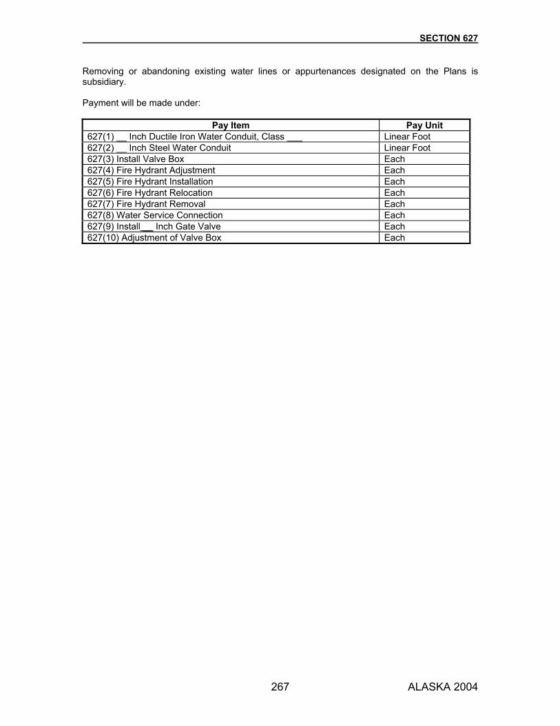
SECTION 627
267 ALASKA 2004
Removing or abandoning existing water lines or appurtenances designated on the Plans is subsidiary. Payment will be made under:
Pay Item Pay Unit 627(1) __ Inch Ductile Iron Water Conduit, Class ___ Linear Foot 627(2) __ Inch Steel Water Conduit Linear Foot 627(3) Install Valve Box Each 627(4) Fire Hydrant Adjustment Each 627(5) Fire Hydrant Installation Each 627(6) Fire Hydrant Relocation Each 627(7) Fire Hydrant Removal Each 627(8) Water Service Connection Each 627(9) Install __ Inch Gate Valve Each 627(10) Adjustment of Valve Box Each

268 ALASKA 2004
SECTION 630
GEOTEXTILE FOR EMBANKMENT SEPARATION AND STABILIZATION
630-1.01 DESCRIPTION. Prepare surfaces and furnish and place geotextiles for embankment separation and/or stabilization as shown in the Plans. 630-2.01 MATERIALS. Use materials that conform to the following:
Geotextiles and Sewing Thread Subsection 729-2.01 630-3.01 CONSTRUCTION. 1. Surface Preparation. Prepare surface by removal of stumps, brush, boulders, and sharp
objects. Fill holes and large ruts with material shown on the Plans or as approved. 2. Geotextile Placement. Unroll geotextile directly onto the prepared surface. Stretch geotextile
to remove any creases or wrinkles. Do not expose geotextiles to the elements for longer than 5 days after removal of protective covering.
a. Separation. Lay geotextile for embankment separation parallel to roadway centerline. On
horizontal curves, place in segment lengths not exceeding those listed in Table 630-1, with butt ends cut to match and sewn or overlapped. On tangents, straighten the geotextile and sew or overlap butt ends.
b. Stabilization. Lay geotextile for embankment stabilization perpendicular to the roadway
centerline. Join segments by sewing or an approved bonding or attachment process.
TABLE 630-1 GEOTEXTILE PLACEMENT ON CURVES
Degree of Curve Maximum Segment Length (ft.)
1 125 2 90 3 75 4 65 5 55 6 50
3. Joining. Join geotextile for embankment separation by sewing or overlapping. Join geotextile
for stabilization by sewing. Use other attachment methods, if approved.
a. Sew seams with a Butterfly or J-Seam. Use a double-thread chain stitch (lock stitch) Bring adjacent sections of geotextile together and fold so that the stitching penetrates four layers of geotextile for the full seam length. Make the stitching line 1-1/4 inches (± 1/4 inch) from the folded edge of the seam and at least 1/2 inch from the free edge of the geotextile. Illustrations showing correct stitch formation and seam configurations are provided in Figure 1.2 (page 21) of the FHWA publication, Geosynthetic Design & Construction Guidelines, FHWA-HI-95-038, May 1995.
b. Overlapped sections must overlap a minimum of 3 feet.

SECTION 630
269 ALASKA 2004
4. Material Placing and Spreading. During placing and spreading, maintain a minimum depth of 12 inches of cover material at all times between the fabric and the wheels or tracks of the construction equipment.
Spread the material in the direction of the fabric overlap. Maintain proper overlap and fabric continuity. If sewn or bonded seams are used, place the cover material and spread in only one direction for the entire length of the geotextile. On weak subgrades spread the cover material simultaneously with dumping to minimize the potential of a localized subgrade failure. Compact using a smooth drum roller. Do not allow construction equipment to make sudden stops, starts, or turns on the cover material.
5. Geotextile Repair.
a. Separation. Overlay torn area with geotextile with a minimum 3 foot overlap around the edges of the torn area. Ensure that the patch remains in place when material is placed over the affected area.
b. Stabilization. Sew or bond according to Subsection 630-3.01.3.
630-4.01 METHOD OF MEASUREMENT. By multiplying plan neat line width by the measured length in final position parallel to installation centerline along the ground surface. No allowance will be made for overlap, whether at joints or patches. 630-5.01 BASIS OF PAYMENT. Material used to fill ruts and holes will be paid for at the unit price for the type of material used. Payment will be made under:
Pay Item Pay Unit 630(1) Geotextile, Separation Square Yard 630(2) Geotextile, Stabilization Square Yard
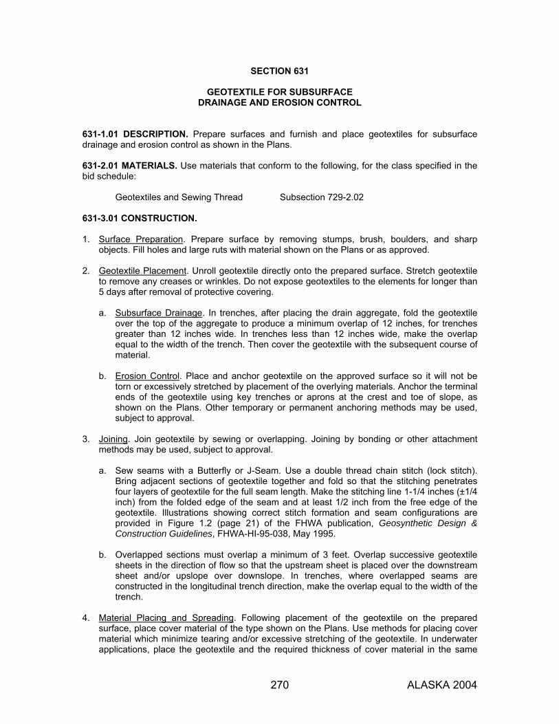
270 ALASKA 2004
SECTION 631
GEOTEXTILE FOR SUBSURFACE DRAINAGE AND EROSION CONTROL
631-1.01 DESCRIPTION. Prepare surfaces and furnish and place geotextiles for subsurface drainage and erosion control as shown in the Plans. 631-2.01 MATERIALS. Use materials that conform to the following, for the class specified in the bid schedule:
Geotextiles and Sewing Thread Subsection 729-2.02 631-3.01 CONSTRUCTION. 1. Surface Preparation. Prepare surface by removing stumps, brush, boulders, and sharp
objects. Fill holes and large ruts with material shown on the Plans or as approved. 2. Geotextile Placement. Unroll geotextile directly onto the prepared surface. Stretch geotextile
to remove any creases or wrinkles. Do not expose geotextiles to the elements for longer than 5 days after removal of protective covering.
a. Subsurface Drainage. In trenches, after placing the drain aggregate, fold the geotextile
over the top of the aggregate to produce a minimum overlap of 12 inches, for trenches greater than 12 inches wide. In trenches less than 12 inches wide, make the overlap equal to the width of the trench. Then cover the geotextile with the subsequent course of material.
b. Erosion Control. Place and anchor geotextile on the approved surface so it will not be
torn or excessively stretched by placement of the overlying materials. Anchor the terminal ends of the geotextile using key trenches or aprons at the crest and toe of slope, as shown on the Plans. Other temporary or permanent anchoring methods may be used, subject to approval.
3. Joining. Join geotextile by sewing or overlapping. Joining by bonding or other attachment
methods may be used, subject to approval.
a. Sew seams with a Butterfly or J-Seam. Use a double thread chain stitch (lock stitch). Bring adjacent sections of geotextile together and fold so that the stitching penetrates four layers of geotextile for the full seam length. Make the stitching line 1-1/4 inches (±1/4 inch) from the folded edge of the seam and at least 1/2 inch from the free edge of the geotextile. Illustrations showing correct stitch formation and seam configurations are provided in Figure 1.2 (page 21) of the FHWA publication, Geosynthetic Design & Construction Guidelines, FHWA-HI-95-038, May 1995.
b. Overlapped sections must overlap a minimum of 3 feet. Overlap successive geotextile
sheets in the direction of flow so that the upstream sheet is placed over the downstream sheet and/or upslope over downslope. In trenches, where overlapped seams are constructed in the longitudinal trench direction, make the overlap equal to the width of the trench.
4. Material Placing and Spreading. Following placement of the geotextile on the prepared
surface, place cover material of the type shown on the Plans. Use methods for placing cover material which minimize tearing and/or excessive stretching of the geotextile. In underwater applications, place the geotextile and the required thickness of cover material in the same
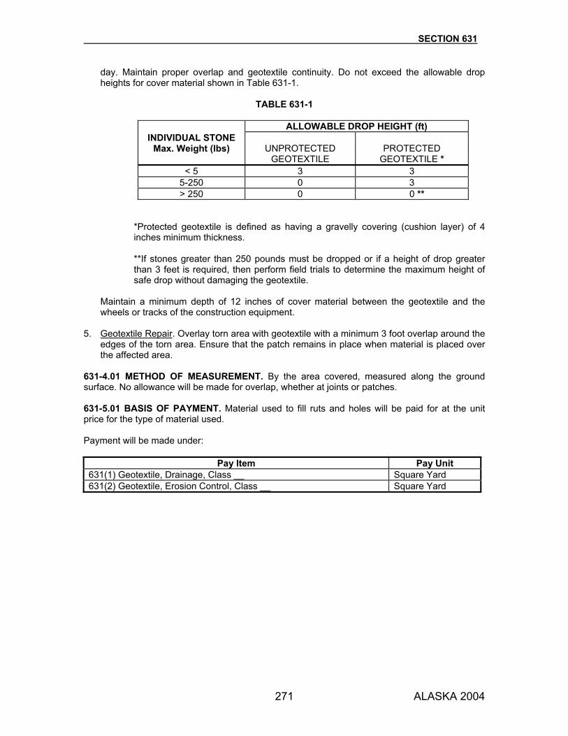
SECTION 631
271 ALASKA 2004
day. Maintain proper overlap and geotextile continuity. Do not exceed the allowable drop heights for cover material shown in Table 631-1.
TABLE 631-1
ALLOWABLE DROP HEIGHT (ft)
INDIVIDUAL STONE Max. Weight (lbs) UNPROTECTED PROTECTED
GEOTEXTILE GEOTEXTILE * < 5 3 3
5-250 0 3 > 250 0 0 **
*Protected geotextile is defined as having a gravelly covering (cushion layer) of 4 inches minimum thickness. **If stones greater than 250 pounds must be dropped or if a height of drop greater than 3 feet is required, then perform field trials to determine the maximum height of safe drop without damaging the geotextile.
Maintain a minimum depth of 12 inches of cover material between the geotextile and the wheels or tracks of the construction equipment.
5. Geotextile Repair. Overlay torn area with geotextile with a minimum 3 foot overlap around the
edges of the torn area. Ensure that the patch remains in place when material is placed over the affected area.
631-4.01 METHOD OF MEASUREMENT. By the area covered, measured along the ground surface. No allowance will be made for overlap, whether at joints or patches. 631-5.01 BASIS OF PAYMENT. Material used to fill ruts and holes will be paid for at the unit price for the type of material used. Payment will be made under:
Pay Item Pay Unit 631(1) Geotextile, Drainage, Class __ Square Yard 631(2) Geotextile, Erosion Control, Class __ Square Yard
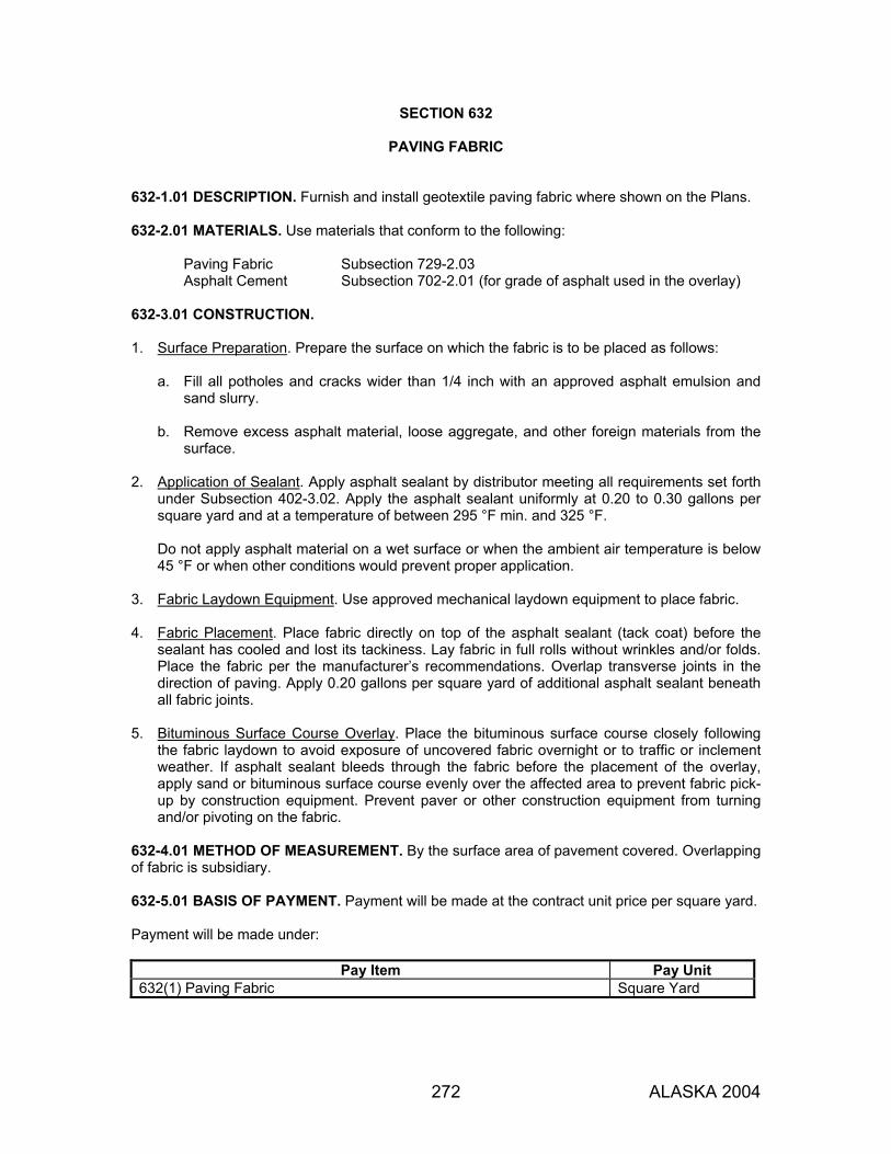
272 ALASKA 2004
SECTION 632
PAVING FABRIC 632-1.01 DESCRIPTION. Furnish and install geotextile paving fabric where shown on the Plans. 632-2.01 MATERIALS. Use materials that conform to the following:
Paving Fabric Subsection 729-2.03 Asphalt Cement Subsection 702-2.01 (for grade of asphalt used in the overlay)
632-3.01 CONSTRUCTION. 1. Surface Preparation. Prepare the surface on which the fabric is to be placed as follows:
a. Fill all potholes and cracks wider than 1/4 inch with an approved asphalt emulsion and sand slurry.
b. Remove excess asphalt material, loose aggregate, and other foreign materials from the
surface. 2. Application of Sealant. Apply asphalt sealant by distributor meeting all requirements set forth
under Subsection 402-3.02. Apply the asphalt sealant uniformly at 0.20 to 0.30 gallons per square yard and at a temperature of between 295 °F min. and 325 °F.
Do not apply asphalt material on a wet surface or when the ambient air temperature is below 45 °F or when other conditions would prevent proper application.
3. Fabric Laydown Equipment. Use approved mechanical laydown equipment to place fabric. 4. Fabric Placement. Place fabric directly on top of the asphalt sealant (tack coat) before the
sealant has cooled and lost its tackiness. Lay fabric in full rolls without wrinkles and/or folds. Place the fabric per the manufacturer’s recommendations. Overlap transverse joints in the direction of paving. Apply 0.20 gallons per square yard of additional asphalt sealant beneath all fabric joints.
5. Bituminous Surface Course Overlay. Place the bituminous surface course closely following
the fabric laydown to avoid exposure of uncovered fabric overnight or to traffic or inclement weather. If asphalt sealant bleeds through the fabric before the placement of the overlay, apply sand or bituminous surface course evenly over the affected area to prevent fabric pick-up by construction equipment. Prevent paver or other construction equipment from turning and/or pivoting on the fabric.
632-4.01 METHOD OF MEASUREMENT. By the surface area of pavement covered. Overlapping of fabric is subsidiary. 632-5.01 BASIS OF PAYMENT. Payment will be made at the contract unit price per square yard. Payment will be made under:
Pay Item Pay Unit 632(1) Paving Fabric Square Yard

273 ALASKA 2004
SECTION 633
SILT FENCE 633-1.01 DESCRIPTION. Furnish, place, maintain, and remove temporary silt fence as shown in the Plans or as directed. 633-2.01 MATERIALS. Use materials that conform to the following:
Geotextile Subsection 729-2.04 Posts Wood, steel, or approved synthetic material.
633-3.01 CONSTRUCTION. 1. Post Installation. Place posts a maximum of 8 feet apart and drive a minimum of 18 inches
into the ground. 2. Geotextile Placement. Install geotextile on posts in a vertical position and support by a wire
mesh fence or self-support system. Set at the height specified in the Contract. Secure the bottom 18 inches of the geotextile on the upslope side of the fence as shown on the Plans. Backfill trench with tamped soil. Join adjacent sections of geotextile only at posts with a minimum of 6 inches overlap.
633-3.02 MAINTENANCE. Maintain the integrity of the fence as long as it is necessary to contain sediment runoff. Inspect daily and correct any deficiencies immediately. Remove and dispose of fence when adequate vegetative growth insures no further erosion of the slopes. Cut off the fabric at ground level and remove the wire and posts. When thickness of trapped sediment is in excess of 4 inches above the ground, either remove sediment from the site or spread sediment uphill of the fence and seed all exposed soil immediately, following the requirements of Section 618. 633-4.01 METHOD OF MEASUREMENT. Section 109. 633-5.01 BASIS OF PAYMENT. The contract price includes maintenance, removal and disposal of the fence, and seeding. Payment will be made under:
Pay Item Pay Unit 633(1) Silt Fence Linear Foot

274 ALASKA 2004
SECTION 634
GEOGRID SOIL REINFORCEMENT 634-1.01 DESCRIPTION. Furnish and install geogrid material at locations shown on the Plans. 634-2.01 MATERIALS. Use materials that conform to the following:
Geogrid Subsection 729-2.05
CONSTRUCTION REQUIREMENTS 634-3.01 WEATHER LIMITATIONS. Do not expose geogrid to the elements for longer than 14 days after removal of protective covering. 634-3.02 SURFACE PREPARATION. 1. Soft Ground (CBR 1-3). Prepare surface by removal of stumps, brush, boulders, and sharp
objects. Fill holes and large ruts with material shown on the Plans or as approved. 2. Firm Ground (CBR >3). Compact and finish subgrade or subbase prior to placement of the
geogrid. 634-3.03 GEOGRID PLACEMENT. Unroll geogrid directly onto the prepared surface. 1. Soft Ground. Overlap geogrid panels a minimum of 24 inches at all joints, in the direction that
fill will be placed. Tie panels together securely with cable ties or hog rings at 20 foot intervals. 2. Firm Ground. Overlap geogrid panels at all joints a minimum of 12 inches, in the direction that
fill will be placed. Tie panels together securely with manufacturer-recommended pins or bars. Hand-tension geogrid and stake to the ground at the edges, overlaps, and in the center of each roll, at 30 foot intervals.
634-3.04 PLACING AND SPREADING COVER MATERIAL. Do not operate equipment on the unprotected geogrid. Spread fill material in the direction of the fabric overlap. 1. Soft Ground. Back dump material onto the geogrid. Spread material ahead with a low ground
pressure dozer to the depth permitted. 2. Firm Ground. Maintain a minimum depth of 6 inches of cover material at all times between
the fabric and the wheels or tracks of the construction equipment. Compact using a smooth drum roller. Do not allow construction equipment to make sudden stops, starts, or turns on the cover material. 634-3.05 GEOGRID REPAIR. Overlay torn area with geogrid with a minimum 3 foot overlap around the edges of the torn area and secure as recommended by the geogrid manufacturer. 634-4.01 METHOD OF MEASUREMENT. By the square yard, in final position, determined by multiplying plan neat line width by the measured length parallel to installation centerline along the ground surface, for installations acceptably completed. No allowance will be made for overlap, whether at joints or patches.

SECTION 634
275 ALASKA 2004
634-5.01 BASIS OF PAYMENT. At the contract unit price per square yard. Material used to fill ruts and holes will be paid for at the unit price for the type of material used. Payment will be made under:
Pay Item Pay Unit 634(1) Geogrid, Type __ Square Yard

276 ALASKA 2004
SECTION 635
INSULATION BOARD 635-1.01 DESCRIPTION. Furnish and install polystyrene insulation board where shown on the Plans. 635-2.01 MATERIALS. Use materials that conform to the following: Insulation Board. AASHTO M 230, Type VI, except that extrusion is not required and the maximum water absorption by weight is 10%, as determined by ASTM C 272. Meet or exceed the specified R value. Sand Blanket. Subsection 703-2.12. 635-3.01 CONSTRUCTION REQUIREMENTS. Prior to placing the insulation board, blade, shape, and compact the area per Section 203. Place a sand blanket leveling course at least 2 inches thick. Set each board accurately to the line and grade established and anchor firmly in place by driving a minimum of 2 wood dowels per panel. Place insulation to the required thickness, using a minimum of two layers. Stagger all joints between layers. Cover the insulation board with 4 inches of sand blanket material prior to placing subsequent lifts. Use approved spreading and compacting equipment. 635-4.01 METHOD OF MEASUREMENT. Section 109. Sand blanket material is subsidiary. 635-5.01 BASIS OF PAYMENT. Payment will be made under:
Pay Item Pay Unit 635(1) Insulation Board MBM

277 ALASKA 2004
SECTION 636
GABIONS 636-1.01 DESCRIPTION. Construct wire gabion bank protection at locations shown on the Plans. 636-2.01 MATERIALS. Use materials that conform to the following:
Wire Subsection 712-2.13 Gabion Backfill Subsection 703-2.11
636-3.01 CONSTRUCTION REQUIREMENTS. Construct gabions to the lines and grades as staked. Meet the details shown on the Plans. Assemble gabion baskets per the manufacturer's recommended procedures. Align each row or tier of gabion baskets before filling the baskets. Install tie wires in both directions horizontally so that layers between ties are not more than 14 inches thick. Space tie wires not more than 14 inches apart horizontally within any gabion basket cell. Loop tie wires around at least 3 meshes of the gabion basket and tie or twist securely. Fill each gabion basket so the lid, when secure, will bear on the gabion filler. Securely fasten gabion baskets to all adjacent baskets, using sufficient wire to provide the same strength as the body of the mesh. Meet Section 204 for all excavation and backfill for gabions. 636-4.01 METHOD OF MEASUREMENT. By the calculated neat line volume of gabion baskets in place using the manufacturer's specified dimensions. 636-5.01 BASIS OF PAYMENT. Excavation for gabions will be paid for under Section 204. Payment will be made under:
Pay Item Pay Unit 636(1) Gabion Cubic Yard

278 ALASKA 2004
SECTION 639
DRIVEWAYS 639-1.01 DESCRIPTION. Construct residential or commercial driveways at the locations shown on the Plans. 639-2.01 MATERIALS. Use materials that conform to the standards for the main roadway. 639-3.01 CONSTRUCTION. Construct driveways to the dimensions shown on the Plans. 639-4.01 METHOD OF MEASUREMENT. By the number of driveways constructed as shown on the Plans or as directed. 639-5.01 BASIS OF PAYMENT. Excavation required beyond the limits of the adjacent mainline is subsidiary. Materials required to construct driveways will be paid for separately under the respective items listed in the bid schedule. Payment will be made under:
Pay Item Pay Unit 639(1) Residence Driveway Each 639(2) Commercial Driveway Each

279 ALASKA 2004
SECTION 640
MOBILIZATION AND DEMOBILIZATION 640-1.01 DESCRIPTION. Perform work and operations necessary to 1. move personnel, equipment, supplies, and incidentals to the project site; 2. establish offices, buildings, and other facilities, except as provided under Section 644; 3. perform other work and operations and pay costs incurred, before beginning construction; 4. complete similar demobilization activities; and 5. furnish required submittals such as as-builts, certificates, payrolls, civil rights reports, and
equipment warranties. 640-2.01 MATERIALS. None. 640-3.01 CONSTRUCTION REQUIREMENTS. None. 640-4.01 METHOD OF MEASUREMENT. 1. When you earn 4% of the original contract amount from other bid items: 40% of the amount
bid for mobilization and demobilization, or 4% of the original contract amount, whichever is less, will be paid.
2. When you earn a total of 8% of the original contract amount from other bid items: An
additional 40% of the amount bid for mobilization and demobilization, or an additional 4% of the original contract amount, whichever is less, will be paid.
3. The remaining balance of the amount bid for this item will be paid after all submittals required
under the Contract are received and approved. 640-5.01 BASIS OF PAYMENT. Payment will be made under:
Pay Item Pay Unit 640(1) Mobilization and Demobilization Lump Sum
280 ALASKA 2004
SECTION 641
EROSION, SEDIMENT, AND POLLUTION CONTROL 641-1.01 DESCRIPTION. Plan, provide, inspect, and maintain control of erosion, sedimentation, water pollution, and hazardous materials contamination. 641-1.02 DEFINITIONS. 1. BMP (Best Management Practices). A wide range of project management practices,
schedules, activities, or prohibition of practices, that when used alone or in combination, prevent or reduce erosion, sedimentation, and/or pollution of adjacent water bodies and wetlands. BMP include temporary or permanent structural and non-structural devices and practices. The Department describes common BMPs in its Alaska Storm Water Pollution Prevention Plan Guide.
2. ESCP (Erosion and Sediment Control Plan). The general plan for control of project-related
erosion and sedimentation. The ESCP normally consists of a general narrative and a map or site plan. It is developed by the Department and included in the project plans and specifications. It serves as a resource for bid estimation and a framework from which the Contractor develops the project SWPPP.
3. Final Stabilization. A point in time when all ground-disturbing activities are complete and
permanent erosion and sediment controls are established and functional. The stabilized site is protected from erosive forces of raindrop impact and water flow. Typically, all unpaved areas except graveled shoulders, crushed aggregate base course, or other areas not covered by permanent structures are protected by either a uniform blanket of perennial vegetation (at least 70% cover density) or equivalent permanent stabilization measures such as riprap, gabions or geotextiles.
4. HMCP (Hazardous Material Control Plan). The Contractor's detailed plan for prevention of
pollution that stems from the use, containment, cleanup, and disposal of hazardous material, including petroleum products generated by construction activities and equipment.
5. NOI. Notice of Intent to commence ground-disturbing activities under the NPDES General
Permit. Use EPA Form 3510-9. 6. NOT. Notice of Termination of coverage under the NPDES General Permit. Use EPA Form
3510-713. 7. NPDES General Permit. The Storm Water General Permit for Large and Small Construction
Activities, issued by the Environmental Protection Agency (EPA) under the National Pollutant Discharge Elimination System (NPDES). It requires an approved SWPPP and NOIs listed as active status by the EPA prior to ground-disturbing activities for the project.
8. SPCC Plan (Spill Prevention, Control and Countermeasure). The Contractor’s detailed plan for oil spill prevention and control measures, that meets the requirements of 40 CFR 112.
9. SWPPP (Storm Water Pollution Prevention Plan). The Contractor’s plan for erosion and sediment control and storm water management under the NPDES General Permit. The SWPPP is developed by the Contractor and describes site-specific controls and management of issues identified for the project. The approved SWPPP replaces the ESCP.

SECTION 641
281 ALASKA 2004
641-1.03 SUBMITTALS. For all projects that disturb one acre or more of ground submit three copies each of your SWPPP and HMCP to the Engineer for approval. Submit one copy of your SPCC Plan (if required under Subsection 641-2.03) to the Engineer. Sign all submittals. Deliver these documents to the Engineer no less than five calendar days prior to the preconstruction conference. The Department will review the SWPPP and HMCP submittals within 14 calendar days. Submittals will be returned to you as either requiring modification, or as approved by the Department. The approved SWPPP must contain a certification, and be signed by you according to the Standard Permit Conditions of the NPDES General Permit, Part 8, Appendix G. You must receive an approved SWPPP before you submit your NOI. For projects that disturb five acres or more of ground, submit a copy of your approved and signed SWPPP, with the required permit fee to the Alaska Department of Environmental Conservation (ADEC) Storm Water Coordinator. Transmit proof of this submission to the Engineer. Submit your signed NOI to EPA (electronic submission may be available). Submit copies of your signed NOI to the Engineer and to ADEC. Transmit proof of your ADEC submission to the Engineer. The Department will transmit the Department’s NOI to the EPA. Allow adequate time for state and federal processing, prior to commencing ground-disturbing activities. The active status NOIs, approved SWPPP, approved HMCP, and submitted SPCC Plan (when required) become the basis of the work required for the project’s erosion, sediment, and pollution control. When the Project is stabilized, as determined by the Engineer, submit your signed NOT to EPA with a copy to the Engineer. The Department will transmit the Department’s NOT to the EPA. 641-2.01 STORM WATER POLLUTION PREVENTION PLAN (SWPPP) REQUIREMENTS. For projects that disturb one acre or more of ground, you must prepare a Storm Water Pollution Prevention Plan. Use the Department's ESCP to develop a SWPPP based on your scheduling, equipment, and use of alternative BMPs. Follow the format presented in the Alaska Storm Water Pollution Prevention Plan Guide. The plan must consider first preventing erosion, then minimizing erosion, and finally trapping sediment before it enters waterways. The plan must address your site-specific controls and management plan for the construction site as well as for all material sites, waste disposal sites, haul roads, and other affected areas, public or private. The plan must also incorporate all the requirements of the project permits. Specify the line of authority and designate your field representative for implementing SWPPP compliance. Designate one representative for each subcontractor who performs earth disturbing activities, or who install and maintain erosion and sediment control measures. 641-2.02 HAZARDOUS MATERIAL CONTROL PLAN (HMCP) REQUIREMENTS. Prepare a HMCP for the handling, storage, cleanup, and disposal of petroleum products and other hazardous substances. (See 40 CFR 117 and 302 for listing of hazardous materials.) List and give the location of all hazardous materials, including office materials, to be used and/or stored on site, and their estimated quantities. Detail your plan for storing these materials as well as disposing of waste petroleum products and other hazardous materials generated by the project. Identify the locations where storage, fueling and maintenance activities will take place, describe the maintenance activities, and list all controls to prevent the accidental spillage of oil, petroleum products and other hazardous materials.

SECTION 641
282 ALASKA 2004
Detail your procedures for containment and cleanup of hazardous substances, including a list of the types and quantities of equipment and materials available on site to be used. Detail your plan for the prevention, containment, cleanup, and disposal of soil and water contaminated by accidental spills. Detail your plan for dealing with unexpected contaminated soil and water encountered during construction. Specify the line of authority and designate your field representative for spill response and one representative for each subcontractor. 641-2.03 SPILL PREVENTION, CONTROL AND COUNTERMEASURE (SPCC) PLAN REQUIREMENTS. Prepare and implement a SPCC Plan that is certified by a licensed Professional Engineer, when required by 40 CFR 112, including: 1. When oil spills may reach navigable waters; and 2. Your total above ground oil storage capacity is greater than 1,320 gallons. Comply with 40 CFR 112 and address the following issues in your SPCC Plan: 1. Operating procedures that prevent oil spills; 2. Control measures installed to prevent a spill from reaching navigable waters; and 3. Countermeasures to contain, clean up, and mitigate the effects of an oil spill. 641-3.01 CONSTRUCTION REQUIREMENTS. Do not begin ground-disturbing work until the EPA has acknowledged receipt of your NOI and Department’s NOI, and has listed them as active status. The EPA will post the status of the NOIs on the EPA website. Post at the construction site: 1. NPDES Permit number, if available, and a copy of the NOI, 2. Name and phone number of your local contact person, and 3. Location of a SWPPP available for viewing by the public. Comply with all requirements of the approved HMCP, the submitted SPCC Plan, and all state and federal regulations that pertain to the handling, storage, cleanup, and disposal of petroleum products or other hazardous substances. Contain, clean up, and dispose of all discharges of petroleum products and/or other materials hazardous to the land, air, water, and organic life forms. Perform all fueling operations in a safe and environmentally responsible manner. Comply with the requirements of 18 AAC 75 and AS 46, Oil and Hazardous Substances Pollution Control. Report oil spills as required by federal, state and local law, and as described in your SPCC Plan. Comply with all requirements of the NPDES General Permit, implement all temporary and permanent erosion and sediment control measures identified in the SWPPP, and ensure that the SWPPP remains current. Maintain all temporary and permanent erosion and sediment control measures in effective operating condition. Perform inspections and prepare inspection reports in compliance with the project SWPPP and the NPDES General Permit. 1. Joint Inspections. Prior to start of construction, conduct a joint on-site inspection with the
Engineer and the Contractor’s field representative to discuss the implementation of the SWPPP.
Conduct the following additional joint on-site inspections with the Engineer: a. During construction, inspect the following at least once every seven days and within 24
hours of the end of a storm exceeding 1/2 inch in 24 hours (as recorded at or near the project site): (1) Disturbed areas that have not been finally stabilized

SECTION 641
283 ALASKA 2004
(2) Areas used for storage of erodible materials that are exposed to precipitation (3) Sediment and erosion control measures (4) Locations where vehicles enter or exit the site
b. Prior to winter shutdown, to ensure that the site has been adequately stabilized and
devices are functional.
c. At project completion, to ensure final stabilization of the project. 2. Winter Inspections. During winter shutdown, conduct inspections at least once every month
and within 24 hours of a storm resulting in rainfall of 1/2 inch or greater. The Engineer may waive monthly inspection requirements until one month before thawing conditions are expected to result in a discharge, if all of the following requirements are met: a. Below-freezing conditions are anticipated to continue for more than one month. b. Land disturbance activities have been suspended. c. The beginning and ending dates of the waiver period are documented in the SWPPP.
3. Inspection Reports. Prepare and submit, within three working days of each inspection, a
report on state Form 25D-100, with the following information: a. A summary of the scope of the inspection b. Name(s) of personnel making the inspection c. The date of the inspection d. Observations relating to the implementation of the SWPPP e. Any actions taken as the result of the inspection f. Incidents of non-compliance
Where a report does not identify any incidents of non-compliance, certify that the facility is in compliance with the SWPPP and NPDES General Permit. You and the Engineer will sign the report according to the Standard Permit Conditions of the NPDES General Permit, Part 8, Appendix G. Include all reports as an appendix to the SWPPP.
Retain copies of the SWPPP, and all other records required by the NPDES General Permit, for at least three years from the date of final stabilization. If unanticipated or emergency conditions threaten water quality, take immediate suitable action to preclude erosion and pollution. Submit amendments to the SWPPP to correct problems identified as a result of any: 1. Storm or other circumstance that threatens water quality, and 2. Inspection that identifies existing or potential problems. Submit SWPPP amendments to the Engineer within seven days following the storm or inspection. Detail additional emergency measures required and taken, to include additional or modified measures. If modifications to existing measures are necessary, complete implementation within seven days. Stabilize all areas disturbed after the seeding deadline within seven days of the temporary or permanent cessation of ground-disturbing activities. Submit a signed NOT to EPA and the Engineer: 1. When the project site (including all material sources, disposal sites, etc.) has been finally
stabilized and all storm water discharges from construction activities authorized by this permit have ceased, or
2. When the construction activity operator (as defined in the NPDES General Permit) has
changed.

SECTION 641
284 ALASKA 2004
If you fail to coordinate temporary or permanent stabilization measures with the earthwork operations in a manner to effectively control erosion and prevent water pollution, the Engineer may suspend your earthwork operations and withhold monies due on current estimates for such earthwork items until all aspects of the work are coordinated in a satisfactory manner. If you fail to: 1. Pursue work required by the approved SWPPP, 2. Respond to inspection recommendations and/or deficiencies in the SWPPP, or 3. Implement erosion and sedimentation controls identified by the Engineer, the Engineer may, after giving you written notice, proceed to perform such work and deduct the cost thereof, including project engineering costs, from your progress payments. 641-4.01 METHOD OF MEASUREMENT. Section 109 and as follows: Items 641(2) and (4) will be measured as specified in the contract or directive authorizing the work. 641-5.01 BASIS OF PAYMENT. The Bid Schedule will include either items 641(1) and (2) or items 641(1), (3), and (4). 1. Item 641(1) Erosion and Pollution Control Administration. At the contract lump sum price for
administration of all work under this Section. Includes, but is not limited to, plan preparation, plan amendments and updates, inspections, monitoring, reporting and record keeping.
2. Item 641(2) Temporary Erosion and Pollution Control. At the prices specified in the Contract
to install and maintain temporary erosion, sedimentation, and pollution control measures. 3. Item 641(3) Temporary Erosion and Pollution Control. At the lump sum price shown on the
bid schedule to install and maintain all temporary erosion, sedimentation, and pollution control measures under the original approved SWPPP and HMCP.
4. Item 641(4) Temporary Erosion and Pollution Control Amendments. At the prices specified in
the Directive for extra, additional, or unanticipated work to install and maintain temporary erosion, sedimentation, and pollution control measures. All work paid under this Item will be shown as amendments to the original approved SWPPP or HMCP.
Temporary erosion and pollution control measures that are required at Contractor-furnished sites are subsidiary. Perform temporary erosion and pollution control measures that are required due to your negligence, carelessness, or failure to install permanent controls as a part of the work as scheduled or ordered by the Engineer, or for your convenience, at your own expense. Permanent erosion and pollution control measures will be measured and paid for under other contract items, when shown on the bid schedule. Payment will be made under:
PAY ITEM PAY UNIT 641(1) Erosion and Pollution Control Administration Lump Sum 641(2) Temporary Erosion and Pollution Control Contingent Sum 641(3) Temporary Erosion and Pollution Control Lump Sum 641(4) Temporary Erosion and Pollution Control Amendments Contingent Sum

285 ALASKA 2004
SECTION 642
CONSTRUCTION SURVEYING AND MONUMENTS
642-1.01 DESCRIPTION. Perform surveying and staking essential for the completion of the project and perform the necessary calculations required to accomplish the work in conformance with the Plans and Specifications and standard engineering and survey practice. Furnish and install survey monuments and monument cases in conformance with the Plans or as directed. Adjust existing monuments and monument cases to conform to the new elevations. 642-1.02 DEFINITIONS. 1. Monument: A fixed physical object marking a point on the surface of the earth; used to
commence or control a survey; mark the boundaries of a parcel of land; or the centerline of a right-of-way corridor. Monuments will be Primary or Secondary, as shown on the Plans.
2. Point: An identified spot located on the surface of the earth. For purposes of this definition, a
point can be a PK nail, wooden hub, rebar, large nail or other structure capable of being utilized as a marker.
3. Witness Corner: A material mark or point usually placed on a property or survey line, at a
known distance from a property corner or other survey point. A witness corner is employed to witness the location of a corner/point that cannot be monumented at its true location.
4. Reference Monument: A material mark or point placed at a known distance and direction
from a property corner or other survey point, usually not on a property or survey line. A reference monument is employed to perpetuate a corner/point that cannot be monumented at its true location or where the corner monument is subject to destruction.
5. Surveyor: The Contractor’s Professional Land Surveyor, currently registered in the State of
Alaska. 642-2.01 MATERIALS. 1. Monument Cases: Use castings meeting AASHTO M 105, Class No. 30A. Coat castings with
a bituminous damp-proof coating. Use tops that bear evenly on the frames. 2. Primary Monument: A minimum 2-inch diameter nonferrous pipe at least 30 inches long, with
a minimum 4-inch flange at the bottom and having magnets attached at the top and bottom. A minimum 2-3/8 inch diameter nonferrous metal cap must be permanently attached to the top. Mark the cap around the outside edge with the words “STATE OF ALASKA DOT&PF". Permanently stamp every monument with the Surveyor’s registration number, the year set, and the point/corner identification. Orient cap so that the data may be read when the reader is facing north, except for centerline monuments that will be oriented to be read facing up-station.
3. Secondary Monument: A minimum 5/8 inch x 30 inches rebar with a 2-inch aluminum cap
attached to the top. Permanently stamp every secondary monument with the Surveyor’s registration number, the point/corner identification, and the year set.

SECTION 642
286 ALASKA 2004
CONSTRUCTION REQUIREMENTS 642-3.01 GENERAL. Use competent, qualified personnel and suitable equipment for the layout work required and furnish traffic control, stakes, templates, straight-edges and other devices necessary for establishing, checking and maintaining the required points, lines and grades. Furnish computer services to accomplish the work. Check data received from the computer for completeness and accuracy. As soon as practical after completion of the work, and in no case later than acceptance of the project, deliver field books, computer forms and computer output data to the Engineer. This data becomes the property of the Department. Supervise construction surveying personnel. Correct errors resulting from the operations of said personnel at your expense. The Contractor is responsible for the accuracy of the work. Work classified as Land Surveying under AS 08.48, and work involving the location, control, and monumentation of construction centerline and right-of-way, must be performed by or under the responsible charge of a Professional Land Surveyor. Follow the Department’s Construction Surveying Requirements. The Department will provide sufficient centerline or reference thereto, and at least 2 benchmarks per mile to enable the establishment of planned elevations and centerline. Keep field notes in standard hardbound notebooks in a clear, orderly, and neat manner consistent with Departmental procedures, including titles, numbering, and indexing. Make field books available for inspection by the Engineer’s project personnel at any time. Store the field books in the Engineer’s Project Office during periods of non-use. Perform the following: 1. Staking necessary to delineate clearing and/or grubbing limits. 2. Cross sections necessary for determination of excavation and embankment quantities,
including intermediate and/or remeasure cross sections as needed. Take cross sections after clearing and grubbing has been completed.
3. Slope staking. 4. Staking of signs, culverts, minor drainage structures and other appurtenances, including the
necessary checking to establish the proper location and grade to best fit the conditions on site.
5. Bridge staking. 6. Setting finishing stakes. 7. Measurement of pay quantities that require measurement. 8. Staking of right-of-way and material source limits. 9. Staking, referencing and other actions required to preserve or restore land monuments and
property corners. 10. Other surveying and staking necessary to complete the project.

SECTION 642
287 ALASKA 2004
When the project centerline points have been established as a part of the Department’s Preconstruction surveys, the Department will furnish the Contractor with copies of the reference field books or control sheets depicting reference point information. Recover these control points and independently verify these references. Reestablish missing points from the Department’s references before clearing, grubbing, or excavation. When the Department has not established the project centerline points but the survey control points were established as a part of the Department’s Preconstruction surveys (as detailed on the project Survey Control Sheet) recover these points and use them as the basis for establishing the project centerline. Verify the position of these points and establish new points where required to replace missing points, before clearing, grubbing, or excavation. Notify the Engineer immediately if a Department-established reference point is discovered to be in error or a reset point is not in harmonious relationship to the adjacent centerline points. Furnish a notekeeper to record field survey notes, including documentation for quantity computations for payment. Ensure that the notekeeper is thoroughly familiar with generally accepted standards of good survey notekeeping practice and the Department’s Construction Surveying Requirements. The Engineer may randomly spot check surveying, staking and computations. After the survey or staking has been completed, provide the Engineer with a minimum of 72 hours notice before performing work, and furnish the appropriate data, to allow for random spot checking. The Department assumes no responsibility for the accuracy of the work. 642-3.02 CROSS-SECTION SURVEYS. When required, obtain right-angle cross sections to the construction centerline at the interval detailed in the Department’s Construction Surveying Requirements. The Department will supply following: 1. Construction Plans and Specifications 2. Design Cross Sections, if any 3. State of Alaska Land Survey Monument Record forms 4. Department’s Construction Surveying Requirements (one copy) 5. Design centerline grades, unless Item 642(2), Office Engineering is used
Perform the following: 1. Furnish hardbound field books (Level, Cross-Section, Slope Stake, etc. ). Use “Rite-in-the-
Rain” or similar weather resistant books. Field books become the property of the Department upon completion of the work.
2. Label the books and number the pages. Make a heading in the appropriate book (date,
weather, names and duties of crew members) at the beginning of each day's work. 3. Update the index of the appropriate book at the end of each day's work. 4. Reduce, check, and adjust level notes. 5. The notekeeper shall compute the cross-section level notes and slope stake catches and a
different crew member shall check the computation on a continual basis in the field. 6. Enter the grade data, shoulder width and/or ditch distance, stationing, slope, etc., in the slope
stake books.

SECTION 642
288 ALASKA 2004
7. Maintain the position and identifying marks of slope stakes and reference points until used for their intended purpose.
8. Correct errors by drawing a line through them and writing the correct entry directly above.
Erasures are not allowed. 9. Return field books or copies of the field books to the Project office at the end of each work
day or as directed. 10. Provide copies of grade sheets and temporary bench mark elevations to the Engineer 48
hours before beginning work on unclassified excavation or embankment. 11. Ensure that survey crews comply with approved traffic control plans. Coordinate crews
activities with the Worksite Traffic Supervisor. 12. Keep a daily survey Party Chief diary, and give a copy of the diary to the Engineer each day.
The diary shall contain the following information: a. Date b Weather c. Crew members’ names and duties d. Type and location of work performed e. Hours worked f. Type of equipment used (brand) and date equipment was double centered or “peg” test
was performed g. Signature of person in responsible charge
13. Submit the survey field notes for the specific area, relating to monument referencing, before
beginning clearing, grubbing, or excavation. 642-3.03 MONUMENTS. Install primary and secondary monuments, as called for in the Plans, at the positions determined by the Department. Reference property markers/corners, monuments, or accessories that may be disturbed or buried during construction. Prepare and record Monument Record Forms in the appropriate Recorder’s Office before disturbing monuments. Monument Record Forms may be obtained from the Engineer. Reestablish monuments in their original position before completion of the project. Prepare and file a Monument Record Form for each reestablished monument. Keep records and report to the Engineer evidence that a monument has been disturbed and is no longer reliable or cannot be located and is presumed to be lost or obliterated. Establish a minimum of two in-line reference points, or three swing-tie reference points in situations where in-line referencing is not desirable. Set reference points outside of the construction limits. Measure distances from the monument to the nearest 0.01 foot. Record referencing of monuments in a separate field book stamped by the Surveyor. Replace existing monuments disturbed by construction with Primary or Secondary Monuments meeting the requirements of subsection 642-2.01. When it is impractical to establish a monument in its original position, install a witness corner (WC). Place the WC to a property corner on the property line when the other property corner that defines said line is existing or there has been sufficient retracement to define said line. In other cases, place a reference monument (RM) perpendicular to the centerline at the station of the original position and at a distance from the original position measured in whole feet. Replacing monuments not shown on the Plans will be considered additional work and paid by 642(3), Three Person Survey Party. Those monuments found that are not shown on the Plans will be recognized by the Department when the Surveyor provides timely field notes identifying type

SECTION 642
289 ALASKA 2004
and location of the monument, and a description of the point the monument marks, with the reason to preserve its location. The Surveyor must complete and stamp a State of Alaska Land Survey Monument Record form for each primary and secondary monument removed, installed, relocated, or replaced. Provide the required survey information on the form in accordance with statutory requirements, including section, township, and range. Meet requirements for recording at the District Recorder’s Office in which the project is located for each monument record. Deliver conforming copies of the recorded forms to the Engineer before monument removal or disturbance and after setting any final monuments requiring monument records. Set each monument and monument case accurately to lines established at the required location and in a manner as to ensure being held firmly in place. Set existing monuments and monument cases to be adjusted to new elevations in the manner and at the elevations directed. 642-3.04 OFFICE ENGINEERING. Calculate finish grades for the roadway as specified according to Plans and/or Specifications. Use information available in the field, on as-builts, or as provided by the Engineer. Perform the work by or under the responsible charge of a Professional Land Surveyor or a Professional Engineer currently Registered in the State of Alaska. 642-3.05 FINAL TRAVERSE. Within 30 days after the Engineer receives a letter stating that construction activities that may disturb the monuments have ceased, the Surveyor shall run a final closed traverse to verify the positional accuracy of installed survey monuments. Begin and end this traverse at different Department-provided control points. Tie into the traverse the primary and secondary monuments placed or replaced and undisturbed Department-provided control points. Do not run the final traverse more than 2.5 miles without a tie to a Department-provided monument/control point. Meet the requirements of a secondary monument for traverse points established during this work. Have the Surveyor sign and stamp a letter that lists each monument and its coordinates and certify that the monuments are each located within 0.2 feet of their proposed position based on the project survey control points provided by the Department. Deliver the certification letter and field notes for this work to the Engineer. 642-4.01 METHOD OF MEASUREMENT. Section 109 and as follows: Item 642(2) Office Engineering. By the project mile along centerline for completed office engineering accepted. Item 642(3) Three Person Survey Party. By the hour for extra, additional, or unanticipated work made necessary by changes in the project, as directed, and as supported by certified payrolls. If staking for extra, additional or unanticipated work, as stated above, is performed by a two person survey party, measurement will be made at 75% of the hours worked and paid under Item 642(3), Three Person Survey Party. If a single person is required for additional office computations or other work requiring only one person, payment will be made at 32% of the hours worked and paid under Item 642(3). Item 642(3A) Three Person Survey Party. Contingent sum work will be measured according to subsections 101-1.03 and 109-1.05. This item, when appearing on the Bid Schedule, will be used only for additional or unanticipated work made necessary by changes in the Contract. Payment will be made according to subsection 109-1.05 Compensation for Extra Work. Items 642(4) through 642(8). The actual number of monuments installed, replaced, or adjusted as shown on the “State of Alaska Land Survey Monument Record” forms delivered to and accepted by the Engineer.

SECTION 642
290 ALASKA 2004
Item 642(9) Reference Existing Monument. The actual number of monuments referenced as shown in the recorded Monument Record Forms delivered to and accepted by the Engineer. Items 642(10) and 642(11). The actual number of monument cases furnished and installed, or adjusted to new elevation, and accepted. Department personnel will perform calculations of pay quantities. 642-5.01 BASIS OF PAYMENT. Construction Surveying and Final Traverse includes field and office work required to accomplish the work, including furnishing necessary personnel, equipment, transportation and supplies. Payment for Final Traverse is based on the Engineer’s acceptance of the Surveyor’s certification letter and field notes. When bid item 642(9) Reference Existing Monument does not appear in the bid schedule, work necessary to reference existing monuments, and prepare and file Monument Record Forms is subsidiary to Item 642(1) Construction Surveying. Five percent of the contract lump sum bid price for Item 642(1) will be withheld until the Monument Record Forms are prepared and recorded in the local Recorder’s Office and accepted by the Engineer. When bid item 642(9) Reference Existing Monument appears in the bid schedule, payment will be made after the Monument Record Forms are prepared and recorded in the local Recorder’s Office and accepted by the Engineer. Office Engineering when required is in addition to Construction Surveying. Both items will appear on the bid schedule. Traffic control devices necessary for the survey parties are considered subsidiary. Survey monuments placed on bridges are subsidiary. Payment for Traffic Control Plans will be paid under Section 643, Traffic Maintenance. Payment will be made under:
Pay Item Unit 642(1) Construction Surveying Lump Sum 642(2) Office Engineering Mile 642(3) Three Person Survey Party Hour 642(3A)Three Person Survey Party Contingent Sum 642(4) Set Primary Monument Each 642(5) Set Secondary Monument Each 642(6) Replace Existing with Primary Monument Each 642(7) Replace Existing with Secondary Monument Each 642(8) Adjust Existing Monument Each 642(9) Reference Existing Monument Each 642(10) Monument Case Each 642(11) Adjust Existing Monument Case Each 642(12) Final Traverse Lump Sum
291 ALASKA 2004
SECTION 643
TRAFFIC MAINTENANCE 643-1.01 DESCRIPTION. Protect and control traffic during the contract. Furnish, erect, maintain, replace, clean, move and remove the traffic control devices required to ensure the traveling public’s safety. Perform all administrative responsibilities necessary to implement this work. Maintain all roadways and pedestrian and bicycle facilities affected by the work in a smooth and passable condition. Construct and maintain approaches, crossings, intersections, and other necessary features throughout the project for the life of the contract. 643-1.02 DEFINITIONS. ATM. When used in this Section, ATM stands for the Alaska Traffic Manual, which is the MUTCD with Alaska Supplement. Construction Phasing Plan. A plan for each phase of the project showing how you will accommodate traffic. Show the sequence of work by segment or phase, if required. Traffic. The movement of vehicles, pedestrians, and bicyclists through road construction, maintenance operations, utility work, or similar operations. Traffic Control Plan (TCP). A drawing or drawings indicating the method or scheme for safely guiding and protecting motorists, pedestrians, bicyclists, and workers in a traffic control zone. The TCP depicts the traffic control devices and their placement and times of use. Traffic Control Zone. A portion of a road construction project, maintenance operation, utility work or similar operation that affects traffic and requires traffic control to safely guide and protect motorists, pedestrians, bicyclists, or workers. 643-1.03 TRAFFIC CONTROL PLAN. Implement an approved TCP before beginning work within the project limits. The TCP includes, but is not limited to, signs, barricades, traffic cones, plastic safety fence, sequential arrow panels, portable changeable message board signs, special signs, warning lights, portable concrete barriers, crash cushions, flaggers, pilot cars, interim pavement markings, temporary lighting, temporary roadways and all other items required to direct traffic through or around the traffic control zone according to these Specifications and the ATM. Address in the TCPs placement of traffic control devices, including location, spacing, size, mounting height and type. Include code designation, size, and legend per the ATM and the ASDS. When a TCP is included in the Plans, use it, modify it, or design an alternative TCP. When a TCP is omitted from the Plans, provide one according to this Section and the ATM. Submit new or modified TCPs to the Engineer for approval. Allow 1 week for the Engineer to review any TCP or each subsequent correction. You may change an approved TCP during construction provided you allow 48 hours for review and the Engineer approves the changes. Certify by signature of the Worksite Traffic Supervisor that all TCPs conform with the ATM and Specifications. The Engineer will not accept the TCP without Worksite Traffic Supervisor’s certification. Have your superintendent review and sign all TCPs before you submit them. In all TCPs you submit, include the periods for which the TCP will be in effect. Provide the name and 24-hour telephone number of the Worksite Traffic Supervisor.

SECTION 643
292 ALASKA 2004
The TCPs, Plans, and Standard Drawings show the minimum required number of traffic control devices. If unsafe conditions occur, the Engineer may require additional traffic control devices. Use of oversize and overweight equipment within the project must conform to an approved TCP, including all traffic control devices these operations require. 643-1.04 WORKSITE TRAFFIC SUPERVISOR. Provide a Worksite Traffic Supervisor responsible for maintaining 24-hour traffic operations. 1. Qualifications. Ensure the Worksite Traffic Supervisor understands ATM requirements, the
Plans, the Specifications, your proposed operations, and is certified as one of the following:
a. Worksite Traffic Supervisor certified by the American Traffic Safety Services Association (ATSSA)
b. Level One Signs and Markings Specialist certified by the International Municipal Signal
Association (IMSA)
Item b requires documentation of at least 12 months of supervisory-level worksite traffic control or 12 months of responsible charge of such work. "Responsible charge" means that the Worksite Traffic Supervisor has been accountable for selecting devices and placing them in the traffic control system, or for continued system operation. The Worksite Traffic Supervisor satisfies this requirement if they have supervised persons performing this labor.
Renew certification no less frequently than every 4 years, and be able to show their certification anytime they are on the project.
2. Duties.
a. Prepare the TCPs and public notices and coordinate traffic control operations between the Project Superintendent and the Engineer.
b. Physically inspect the condition and position of all traffic control devices used on the
project at least once each day and once each night. Ensure that traffic control devices work properly, are clean and visible, and conform to the approved TCP. Complete and sign a detailed written report of each inspection on the form provided by the Engineer within 24 hours.
c. Supervise the repair or replacement of damaged or missing traffic control devices. d. Review and anticipate traffic control needs. Make available proper traffic control devices
necessary for safe and efficient traffic movement. e. Review work areas, equipment storage, and traffic-safety material handling and storage. f. Hold traffic safety meetings with superintendents, foremen, subcontractors, and others as
appropriate before beginning construction, prior to implementing a new TCP, and as directed. Invite the Engineer to these meetings.
g. Supervise all traffic control workers, flaggers, and pilot car drivers. h. Certify that all flaggers are certified as required by Subsection 643-3.04.4. Submit a copy
of all flagger certifications to the Engineer.

SECTION 643
293 ALASKA 2004
643-1.05 CONSTRUCTION PHASING PLAN. Submit a Construction Phasing Plan for approval no less than 5 working days prior to the preconstruction conference. Include the following: 1. Name and 24-hour telephone numbers of the Worksite Traffic Supervisor. Also include their
resume and written verification of their credentials. 2. A plan for each phase or segment of the project. 3. TCPs for the first phase of the project. Show permanent and temporary traffic control
measures, including the times each TCP will be used. Submit any changes to the Engineer for approval 7 days before proposed implementation. 643-1.06 TRAFFIC MAINTENANCE SETUP. When shown on the bid schedule, Traffic Maintenance Setup items are site specific and are detailed as individual TCPs on the plan sheets. They depict the method or scheme required to route traffic safely and efficiently when any of the following restrictions occur: 1. Lane Closure. The closure of one or more lanes on a roadway. 2. Detour. The redirection of traffic through or around a traffic control zone. 3. Road Closure. The closure of a roadway with or without a specified detour route. 4. One Lane Road. A two-way roadway reduced to a single-lane roadway with flaggers, pilot
cars, traffic signals, stop signs, or yield signs. 643-2.01 MATERIALS. Provide traffic control devices meeting the following requirements: 1. Signs. Use signs, including sign supports, that conform to Section 615, the ATM, and ASDS.
a. Construction Signs: Regulatory, guide, or construction warning signs designated in the ASDS.
b. Permanent Construction Signs: As designated on the Plans or an approved TCP. c. Special Construction Signs: All other signs are Special Construction Signs. Neatly mark
the size of each sign on its back in 3-inch black numerals.
2. Portable Sign Supports. Use wind-resistant sign supports with no external ballasting. Use sign supports that can vertically support a 48 X 48 inch traffic control sign at the height above the adjacent roadway surface required by the ATM.
3. Barricades and Vertical Panels. Use barricades and vertical panel supports that conform to
the ATM. Use Type III Barricades at least 8 feet long. Use reflective sheeting that meets AASHTO M 268 Type II or III.
4. Portable Concrete Barriers. Use portable concrete barriers that conform to the Plans. For
each direction of traffic, equip each 10-foot section of barrier with at least two side-mounted retroreflective reflectors or a continuous 4-inch wide horizontal retroreflective stripe mounted 6 inches below the top of the barrier. Use yellow reflectors or stripe if you use barriers at centerline. Use white reflectors or stripe if you use barriers on the roadway shoulder.
5. Warning Lights. Use Type A (low intensity flashing), Type B (high intensity flashing) or Type
C (steady burn) warning lights that conform to the ATM. 6. Drums. Use plastic drums that conform to the requirements of the ATM. Use reflective
sheeting that meets AASHTO M 268 Type II or III. 7. Traffic Cones and Tubular Markers. Use reflectorized traffic cones and tubular markers that
conform to the requirements of the ATM. Use traffic cones and tubular markers at least 28 inches high. Use reflective sheeting that meets AASHTO M 268 Type II or III.

SECTION 643
294 ALASKA 2004
8. Interim Pavement Markings. Apply markings according to Section 670 and the manufacturer's recommendations. Use either: a. Paint meeting Subsection 708-2.03 with glass beads meeting Subsection 712-2.08, b. Preformed Marking Tape (removable or non-removable) meeting Subsection 712-2.14, or c. Temporary Raised Pavement Markers meeting Subsection 712-2.15 or 712-2.16, as
appropriate. 9. High-Level Warning Devices. Use high-level warning devices that conform to the ATM. 10. Temporary Crash Cushions. Use approved temporary crash cushions meeting the ATM. Use
reflective sheeting that meets AASHTO M 268 Type II or III. Do not use permanent crash cushions as temporary crash cushions. Use sand or water filled crash cushions only when the forecasted temperature during their use is above 40 oF.
11. Sequential Arrow Panels. Use Type A (24 X 48 inch), Type B (30 X 60 inch) or Type C (48 X
96 inch) panels that conform to the ATM. 12. Portable Changeable Message Board Signs. Use truck or trailer mounted portable
changeable message board signs with a self contained power supply for the sign and with the following features: a. Message sign panel large enough to display 3 lines of 9 inch high characters b. Eight character display per message line c. Fully programmable message module d. The capacity to create, preview, and display new messages and message sequences e. A waterproof, lockable cover for the controller keyboard f. An operator’s manual, a service manual, and a wiring diagram g. Quick release attachments on the display panel cover h. Variable flash and sequence rates i. Manual and automatic dimming capabilities on lamp bulb matrix models j. Locate the bottom of the sign panel at least 7 feet above the pavement k. Operate with a battery pack a minimum of 2 hours under full load
13. Plastic Safety Fence. Use 4 foot high construction orange fence manufactured by one of the
following companies, or an approved equal: a. “Safety Fence” by Services and Materials Company, Inc., 2200 South “J” Street,
Elwood, Indiana, 46036. Phone (800) 428-8185. b. “Flexible Safety Fencing” by Carsonite, 1301 Hot Springs Road, Carson City,
Nevada, 89706. Phone (800) 648-7974. c. “Warning Barrier Fence” by Plastic Safety Systems, Inc. P.O. Box 20140, Cleveland,
Ohio, 44120. Phone (800) 662-6338. 14. Temporary Sidewalk Surfacing. Provide temporary sidewalk surfacing as required by an
approved TCP and the following: a. Use plywood at least 1/2 inch thick for areas continuously supported by subgrade. Use
plywood at least 1 inch thick for areas that are not continuously supported. b. Do not use unsupported 1-inch plywood longer than 30 inches. c. Use plywood with regular surfaces. Do not overlap plywood joints higher than 1 inch. d. Use a method that will withstand 25 mph wind velocities to hold temporary surfacing in
place. 15. Temporary Guardrail. Use temporary guardrail that meets Section 606, except that posts may
require placement under special conditions, such as in frozen ground. 16. Flagger Paddles. Use flagger paddles with 24 inches wide by 24 inches high sign panels, 8
inch Series C lettering (see ASDS for definition of Series C), and otherwise conform to the ATM. Use reflective sheeting that meets AASHTO M 268 Type II or III.
SECTION 643
295 ALASKA 2004
643-2.02 CRASHWORTHINESS. Submit documentation, by the method indicated, that the following devices comply with the requirements of National Cooperative Highway Research Program (NCHRP) Report 350 (Test Level 3) on the given schedule.
Work Zone Traffic Control Device Compliance with NCHRP 350 Category
Devices
Compliance Required for New Devices*
Full Compliance Required**
Method of Documentation
1 Cones, candles, drums w/o attachments, delineators
10/1/98 1/1/02 Manufacturer's Certification for devices exceeding height and weight limits
2 Barricades, portable sign supports, drums w/lights, other devices weighing less than 100 pounds but not included in category 1
10/1/00 1/1/04 FHWA approval letter
3 Truck mounted attenuators and portable crash cushions
10/1/98 1/1/02 FHWA approval letter
Portable concrete barriers 10/1/02 1/1/08 FHWA approval letter * All devices purchased after this date ** All devices used after this date Category 1 devices that exceed the following weights and heights require certification that they meet the evaluation criteria of NCHRP Report 350, Test Level 3. This certification may be a one-page affidavit signed by the vendor. Documentation supporting the certification (crash tests and/or engineering analysis) must be kept on file by the certifying organization. No certification is required for devices within the weight and height limitations.
Device Composition Weight Height Cones Rubber 20 lb. 36 in. Plastic 20 lb. 48 in. Candles Rubber 13 lb. 36 in. Plastic 13 lb. 36 in. Drums Hi Density Plastic 77 lb. 36 in. Lo Density Plastic 77 lb. 36 in. Delineators Plastic or Fiberglass N/A 48 in.
Category 2 and the listed category 3 devices may be documented by submitting an official letter from the Federal Highway Administration stating that the device meets NCHRP 350 Test Level 3 requirements. FHWA acceptance letters for many devices may be found on the FHWA’s web site (http://www.fhwa.dot.gov/), under FHWA Programs, Safety, NCHRP Report 350 - Roadside Hardware. Submit documentation of compliance to the Engineer before using devices on the project. 643-3.01 GENERAL CONSTRUCTION REQUIREMENTS. Keep the work, and portions of the project affected by the work, in good condition to accommodate traffic safely. Provide and maintain traffic control devices and services inside and outside the project limits, day and night, to guide traffic safely. Unless otherwise provided in this Section, keep all roadways, business accesses, and pedestrian facilities within the project limits open to traffic. Obtain the Engineer’s approval before temporarily closing residential, commercial, or street approaches. Provide access through the project for
SECTION 643
296 ALASKA 2004
emergency vehicles and school and transit buses. Properly sign and/or flag all locations where you must redirect or stop the traveling public. Stop your equipment at all points of intersection with the traveling public unless an approved TCP shows otherwise. Continue to operate all illumination and signalization according to the requirements of Subsection 660-3.09. When moving approach lanes, realign signal heads as necessary according to the ATM. Coordinate any modifications to existing traffic signals with the agency that maintains and operates them. Operate flood lighting at night according to the ATM. Adjust flood lighting so that it does not shine into oncoming traffic. Provide and maintain safe routes for pedestrians and bicyclists through or around traffic control zones at all times, except when regulations prohibit pedestrians or bicyclists. 643-3.02 ROADWAY CHARACTERISTICS DURING CONSTRUCTION. Obtain an approved TCP before reducing existing roadway lane and shoulder widths before starting construction. Maintain a clear area with at least 2 feet between the edge of traveled way and the work area. Use barricades, traffic cones, or drums to delineate this area. Place traffic control devices on the work side of the clear area. Space them according to the ATM. If you are allowed to maintain traffic on an unpaved surface, conduct construction to provide a smooth and even surface that public traffic can use at all times. Properly crown the roadbed surface for drainage. Before beginning other grading operations, place sufficient fill at culverts and bridges to permit traffic to cross smoothly and unimpeded. Use part-width construction techniques when routing traffic through roadway cuts or over embankments under construction. Excavate the material or place it in layers. Alternate construction activities from one side to the other. Route traffic over the side opposite the one under construction. You may detour traffic when the Plans or an approved TCP allows it. Maintain detour routes so that traffic can proceed safely. When detours are no longer required, obliterate the detour. Topsoil and seed appropriate areas. If you cannot maintain two-way traffic on the existing roadway or detour, you may use half-width construction or a road closure if it is shown on an approved TCP. Make sure the TCP indicates closure duration and conditions. Schedule roadway closures so you do not delay school buses and peak-hour traffic. For road closures, post closure-start and road-reopen times at the closure site, within view of waiting traffic. 643-3.03 PUBLIC NOTICE. Make sure the Worksite Traffic Supervisor gives notices of major changes, delays, lane restrictions, or road closures to local officials and transportation organizations, including but not necessarily limited to:
• Alaska Carriers Association • Alaska Trucking Association • Alaska State Troopers • Division of Measurement Standards • Local Police Department • Local Fire Department • Local Government Traffic Engineer • School and Transit Authorities • Local Emergency Medical Services • Local Media (newspapers, radio, television) • Railroads (where applicable) • U.S. Postal Service
SECTION 643
297 ALASKA 2004
• Major Tour Operators
Provide local traffic enforcement and maintenance agencies 24 hour notice before shutting down a traffic signal system. Provide the Alaska State Troopers, local police and fire department with the radio frequencies used on the project and the 24-hour telephone numbers of the Worksite Traffic Supervisor and the Project Superintendent. Tell them to use these numbers to alert you when emergency vehicles must pass through the project. When notified of emergencies, use all equipment and make every necessary effort to expedite rapid passage. 643-3.04 TRAFFIC CONTROL DEVICES. Before starting construction, erect permanent and temporary traffic control devices required by the approved TCPs. Use traffic control devices only when they are needed. The Engineer will determine advisory speeds when necessary. For lane closures on multilane roadways, use sequential arrow panels. During hours of darkness when required by the approved TCP use flashing warning lights to mark obstructions or hazards and steady-burn lights for channelization. Use only one type of traffic control device in a continuous line of delineating devices, unless otherwise noted on an approved TCP. Use drums or Type II barricades for lane drop tapers. During non-working hours and after completing a particular construction operation, remove all unnecessary traffic control devices. Store all unused traffic control devices in a designated storage area which does not present a nuisance or visual distraction to traffic. If sign panels are post mounted and cannot be readily removed, cover them entirely with either metal or plywood sheeting. Completely cover signal heads with bags. Keep signs, drums, barricades, and other devices clean at all times. Use only traffic control devices that meet the requirements of the “Acceptable” category in ATTSA “Quality Standards for Work Zone Traffic Control Devices”. Immediately replace any devices provided under this Section that are lost, stolen, destroyed, inoperable or deemed unacceptable while used on the project. Stock repair parts for each Temporary Crash Cushion used on the project. Repair damaged crash cushions within 24 hours. All items paid under this Section remain your property. Remove them after completing the project. 1. Embankments. Install portable concrete barrier, plastic drums, barricades, tubular markers,
plastic safety fence, and cones as specified on the Plans or TCPs to delineate open trenches, ditches, other excavations and hazardous areas when they exist along the roadway for more than one continuous work shift.
2. Adjacent Travel Lane Paving. Limit pavement-edge and lane-edge drop-offs as specified in
Section 401. When paving is deeper than 2 inches and you cannot finish paving adjacent travel lanes or paved shoulders to the same elevation before the end of the paving shift, install one of the following, as appropriate: CW24-1 (Uneven Lanes), CW8-9A (Low Shoulder), CW14-3 (No Passing Zone), R4-1 (Do Not Pass), and R4-2 (Pass with Care). If the section is longer than 1/2 mile, place additional signs every 1500 feet.
3. Fixed Objects. Use flashing warning lights on all vehicles when they are working within 15
feet of the edge of traveled way. Use emergency flashers, flashing strobes or rotating beacons.

SECTION 643
298 ALASKA 2004
Locate private vehicles, idle construction equipment, construction material stockpiles and other items deemed by the Engineer to be fixed objects at least 30 feet from the edge of traveled way at all times. Do not park equipment in medians. If you cannot meet the preceding restrictions because of land features or lack of right-of-way, park equipment as far away as practical but at least 15 feet from the edge of traveled way, as approved by the Engineer. Use drums or Type II barricades with flashing warning lights to delineate parked equipment. These traffic control devices are subsidiary.
4. Flagging. Furnish trained and competent flaggers and all necessary equipment, including
lighting of the flagging position during nighttime operations, to control traffic through the traffic control zone. The Engineer will approve each flagging operation before it begins and direct adjustments as conditions change.
Flaggers must be certified by one of the following: a. Flagging Level I Certification by IMSA b. Flagger Certification by ATTSA
Acceptable substitutions for items a. and b. are certified ATSSA Worksite Traffic Supervisors, IMSA Work Zone Traffic Safety Specialists, IMSA Signs and Markings Specialists and ATSSA Flagging Instructors. Renew flagger training and certification no less frequently than every 4 years. Flaggers must be able to show their flagger certification anytime they are on the project. Flaggers must maintain their assigned posts at all times, unless another qualified flagger relieves them, or you no longer need to flag traffic. Remove, fully cover, or lay down flagger signs when no flagger is present. Keep the flaggers’ area free of encumbrances, such as parked vehicles, so that flaggers can be seen easily. Provide approved equipment for two-way radio communications between flaggers when flaggers are not in plain, unobstructed view of each other.
Obtain the Engineer’s written approval before flagging signalized intersections. When you flag a signalized intersection, either turn off and cover the traffic signal or place it in the All-Red Flash mode. Coordinate changing traffic signal modes and turning off or turning on traffic signals with the agency responsible for signal maintenance and operation and the Engineer. Get their written approval in advance. Use double sided stop/stop paddles when flagging a signalized intersection.
5. Pilot Cars. You may use pilot cars if the route through a traffic control zone which is
particularly hazardous, involved, or frequently altered to preclude adequate signing, or if the Engineer deems one-way traffic necessary. Do not use pilot cars to avoid localized traffic control at several locations.
Organize construction operations so the total of all stoppages experienced by a vehicle traveling through a project does not exceed 20 minutes. However, this does not imply that you may allow 20 minutes in all cases. Coordinate multiple pilot-car operations within a project or adjoining projects to minimize inconvenience to the traveling public. You may use two or more pilot cars to provide two-way traffic through the traffic control zone to reduce the waiting period. The flagger or pilot car operator must record each pilot car’s departure time in a bound field book furnished by the Engineer. Whenever practical, the flagger should tell the motorist the reason for and approximate length of the delay. Make every reasonable effort to yield right-of-way to the public and prevent excessive delay.

SECTION 643
299 ALASKA 2004
Use an automobile or pickup as the pilot car, with your company logo prominently displayed. Equip the pilot car with a two-way radio for contact with flaggers and other pilot cars. Mount a G20-4 sign (Pilot Car Follow Me) on the rear at least 5 feet above the driving surface. Identify the last vehicle in the column. When pilot cars are authorized, use them before beginning work and continue until no longer necessary or until you have properly placed and checked functioning of all traffic control devices required for non-working hours.
6. Street Sweeping and Power Brooming. Keep free of loose material all paved portions of the
roadway and haul routes open to the public, including sections of roadway off the project where your operations have deposited loose material. Use a power broom that can eject the material outside the traveled way. Use a street sweeper that can collect the material.
7. Watering. Furnish, haul, and place water for dust control and pavement flushing, as directed.
Use water trucks that can provide a high-pressure water stream to flush the pavement and a light-water spray to control dust. If the flushing operations contaminate or fill adjacent catch basins, clean and restore them to their original condition. This requirement includes sections of roadway off the project where flushing is required. The Engineer will control water application.
If you take water from a lake, stream, or other natural water body, first obtain a water removal permit from the Alaska Department of Natural Resources. Comply with the Alaska Department of Fish and Game screening requirements for all water removal operations.
8. Portable Changeable Message Board Signs. Furnish Changeable Message Signs when
approved on a TCP. Display only messages approved on the TCP. Follow application guidelines in the ATM.
643-3.05 AUTHORITY OF THE ENGINEER. When the Engineer believes existing conditions may adversely affect the traveling public’s safety and/or convenience, you will receive a written notice. The notice will state the defect(s), the corrective action(s) required, and the time required to complete such action(s). If you fail to take corrective action(s) within the specified time, the Engineer will immediately close down the offending operations until you correct the defect(s). The Engineer may require outside forces to correct unsafe conditions. The cost of work by outside forces will be deducted from any monies due under the terms of this Contract. 643.3.06 TRAFFIC PRICE ADJUSTMENT. A Traffic Price Adjustment, under Item 643(23), will be assessed for unauthorized lane closures or reductions. Authorized lane closures and/or lane reductions are those shown in the Contract, an approved TCP, or authorized in writing. Unauthorized lane reductions include unacceptable driving surfaces, such as severe bumps, ruts, washboarding, potholes, excessive dust or mud, and non-conforming or out of place traffic control devices. The Engineer will make the sole determination as to whether the roadway is acceptable for full unimpeded use by the public. Adjustment Rates are listed in Table 643-1. These rates are liquidated damages which represent highway user costs, based on Average Daily Traffic (ADT). The Engineer will use the rate shown for the current ADT for this project, as published in the Regional Traffic Volume Report prepared by the Department's Planning Section.
SECTION 643
300 ALASKA 2004
TABLE 643-1 ADJUSTMENT RATES
Published ADT
Dollars/Minute of Delay/Lane
Less than 1,000
$2 1,000-4,999
$10
5,000-9,999
$30 10,000+
$40
643-3.07 MAINTENANCE OF TRAFFIC DURING SUSPENSION OF WORK. Approximately one month before you suspend work for the season, schedule a preliminary meeting with the Engineer and Maintenance & Operations to outline the work you expect to complete before shutdown and the anticipated roadway condition. Schedule a field review with the Department for winter maintenance acceptance. At the field review the Engineer will prepare a punch list for implementation before acceptance. To be relieved of winter maintenance responsibility, leave all roads with a smooth and even surface for public use at all times. Properly crown the roadbed surface for drainage and install adequate safety facilities. Make sure all illumination and signals, including vehicle detectors, are in good working order. After the project is accepted for winter maintenance and until you are ordered to resume construction operations, the Department is responsible for maintaining the facility. The Department will accept maintenance responsibility only for portions of the work that are open to the public, as determined by the Engineer. The Department will not accept maintenance responsibility for incomplete work adjacent to accepted roads. You are responsible for maintaining all other portions of the work. The Engineer will issue a letter of “Acceptance for Winter Maintenance” that lists all portions of the work that the Department will maintain during a seasonal work suspension. You retain all contractually required maintenance responsibilities until you receive this letter. If you suspend work due to unfavorable weather (other than seasonal) or due to your failure to correct unsafe conditions, carry out Contract provisions, or carry out the Engineer’s orders, you must bear all costs for traffic maintenance during the suspended period. When you resume work, replace or renew any work or materials lost or damaged during temporary use. If the Department caused damage during winter suspension, payment will be made for repairs by unit pay item or in accord with Subsection 109-1.05, Compensation for Extra Work. When the Engineer directs, remove any work or materials used in the temporary maintenance. Complete the project as though work has been continuous. 643-3.08 CONSTRUCTION SEQUENCING. The construction sequencing detailed in these provisions, the Special Provisions, and the Plans is suggested only. You may propose alternative construction sequencing. Throughout the project, maintain the existing roadway configuration (such as the number of lanes and their respective widths) except for restrictions to traffic allowed in the Special Provisions or on the Plans, and addressed through approved TCPs. A restriction to traffic is any roadway surface condition, work operation, or traffic control setup that reduces the number of lanes or impedes traffic. Obtain an approved TCP before restricting traffic. Do not restrict traffic or shut down signals during the times listed in the Special Provisions.

SECTION 643
301 ALASKA 2004
643-3.09 INTERIM PAVEMENT MARKINGS. Place permanent or interim pavement markings according to this Subsection, details shown on the Plans, approved TCPs, and Parts III and VI of the ATM before opening existing paved roadways, temporary paved roadways, detours, interim paving lifts, and roadways with seal coats and surface treatments for more than one continuous work shift. This work may include restriping the existing roadway before beginning construction, before seasonal suspension, and/or after seasonal suspension. Remove conflicting pavement markings according to Subsection 670-3.04, Paint Removal, or cover them with black removable preformed marking tape. Mark existing roadway sections that will be opened to traffic during the winter. Mark over the existing lines and markings, unless shown otherwise on the Plans or an approved TCP. Maintain all interim pavement markings for their intended life including reapplication when necessary. There will be no compensation to upgrade interim pavement markings required for work operations lasting up to 2 weeks. Use only temporary raised pavement markers or removable preformed retroreflective marking tape as interim pavement markings on final pavement surfaces. Completely remove and dispose of them when you place the final markings. Completely remove any residual adhesive that might misguide motorists. Place final pavement markings on finished pavement surfaces and interim pavement surfaces before suspending work for the winter. Stage construction to avoid routing traffic over conflicting markings for more than one continuous workshift. If you route traffic over conflicting markings during a workshift, delineate the roadway with a complement of warning signs, channelizing devices, and flaggers as required by the ATM. Use only temporary raised pavement markers meeting Subsection 712-2.16 as interim markings on seal coat and surface treatment pavements. Install the markers according to the manufacturer’s instructions before applying the asphalt surface material and cover coat. Remove the vinyl protective covers after applying the asphalt pavement. On multicourse surface treatments, install the temporary raised pavement markers after applying the full width of the first layer of cover coat. Install the markers on each day's completed surface before removing the pilot car operations and allowing unescorted traffic on the surface treatment. Do not place final pavement markings until traffic has traveled over the seal coat or surface treatment for at least 14 days. Apply final pavement markings within 10 days of completing the final sweeping or brooming of the mainline seal coat or surface treatment. 643-4.01 METHOD OF MEASUREMENT. Section 109 and as follows. Quantities will not be measured during winter suspension of work. 1. Traffic Maintenance. Calendar Day: Every day shown on the calendar, beginning and ending
at midnight. Measurement begins on the day following your receipt of the Notice to Proceed or on the first day of work at the project site, whichever is later, and ends on the date of project completion.
2. Traffic Control Device Items. By the number of units of each bid item shown on the bid
schedule (or the Traffic Control Rate Schedule, if item 643(25), Traffic Control, is included) that are installed, accepted, and operational. Incomplete or unsatisfactory devices will not be measured. Special Construction Signs are measured by the total area of legend-bearing sign panel, as determined under Subsection 615-4.01. Items measured by the day are for each item per 24-hour period.

SECTION 643
302 ALASKA 2004
3. Traffic Maintenance Setup Items. By each lane closure or one-lane road in place per hour. By each detour or road closure in place per 24-hour period.
4. Portable Concrete Barrier. By each nominal 10-foot section placed to protect or channelize
traffic as specified on the approved TCPs. Each transition piece (sloping end) will be measured as a single section. For the initial placement and each subsequent relocation when moved more than 10 feet in any direction.
5. Temporary Crash Cushion. By each acceptable installation. 6. Interim Pavement Marking. By the single-stripe station. A single stripe is a marking or a
temporary raised pavement marker 4 inches wide. Wider striping is measured in multiples of 4 inches. Centerline gaps are not deducted from measurements.
7. Flagging and Pilot Car. By the number of approved hours, supported by certified payroll. 8. Street Sweeping and Power Brooming. By the number of operated hours, supported by
certified payroll and approved by the Engineer. 9. Watering. By the 1,000 gallons (M-Gallon) of water applied. The Engineer may specify
measurement by weight or volume. If by weight, convert to gallons at 8.34 pounds per gallon. If by volume, convert to gallons at 7.48 gallons per cubic foot.
10. Traffic Price Adjustment. By each minute that any lane of traffic is not open to full use by the
traveling public, measured to the nearest minute. The Engineer will determine whether the roadway is opened to full use.
11. Traffic Control. By the units specified in the Special Provisions. 12. Portable Changeable Message Board Sign. By the 24-hour period for each sign, as shown on
an approved TCP and displaying an approved message. 13. Plastic Safety Fence. By the linear foot, as placed, to protect or channelize pedestrian traffic
as shown on an approved TCP. Any adjustments in configuration of the fence at the same location that does not result in an increased amount of fence is not measured. Opening and closing the fence to gain access to and from the worksite is not measured.
14. Temporary Sidewalk Surfacing. By the square yard as shown on an approved TCP. 15. Temporary Guardrail. By the linear foot, including end treatments, as shown on an approved
TCP. 643-5.01 BASIS OF PAYMENT. 1. Traffic Maintenance. The contract price includes all resources required to provide the
Worksite Traffic Supervisor, all required TCPs and public notices, the Construction Phasing Plan, and the maintenance of all roadways, approaches, crossings, intersections and pedestrian and bicycle facilities, as required. This item also includes any Traffic Control Devices required but not shown on the bid schedule.
Items required by the Contract that are not listed on the bid schedule or not included in other items are subsidiary to Item 643(1) or 643(2) Traffic Maintenance, except the following:
Traffic Price Adjustment Traffic Maintenance Setup

SECTION 643
303 ALASKA 2004
2. Traffic Control Device Items. The contract price includes all resources required to provide, install, maintain, move, and remove the specified devices. Warning lights, high-level warning devices, vertical panels, and sign supports required for traffic control devices are subsidiary.
3. Traffic Maintenance Setup Items. Each setup consists of all traffic control devices, flaggers,
pilot cars, and subsidiary items necessary to implement the TCP shown on the Plans. Warning lights, high-level warning devices, vertical panels, and sign supports required for traffic control devices are subsidiary.
Construction and obliteration of temporary roadways, when required on the Plans or approved TCP under a traffic maintenance setup item, is paid for under their respective roadway pay items. When topsoil or seeding is required for detours, payment will be made under Sections 620 and/or 618.
4. Portable Concrete Barrier. The contract price includes all resources required to provide,
install, maintain, move 10 feet or less, and remove each barrier. 5. Temporary Crash Cushion. The contract price includes all resources required to provide,
install, maintain, repair, and remove each crash cushion. 6. Interim Pavement Marking. The contract price includes all resources required to provide,
install, maintain, and remove the specified markings. Installation of word and symbol markings are subsidiary. The No-Passing Zone signing, described in Subsection 643-3.04, is subsidiary.
7. Flagging and Pilot Car. The contract price includes all required labor, vehicles, radios, flagger
paddles and pilot car signs, and transportation to and from the worksite. 8. Street Sweeping and Power Brooming. The contract price includes all resources required to
keep the roadway free of loose material. Time required to empty the street sweeper is subsidiary.
9. Watering. The contract price includes all resources required to provide watering, as directed. 10. Traffic Price Adjustment. If Item 643(23), Traffic Price Adjustment, is shown on the bid
schedule, the total value of this contract will be adjusted, for lane closures or delays at the rates listed in Table 643-1.
11. Traffic Control. Payment for Item 643(25), Traffic Control, will be made at the unit rate value
contained in the Traffic Control Rate Schedule shown in the Special Provisions for the accepted units of traffic control devices.
12. Portable Changeable Message Board Sign. The contract price includes all resources required
to furnish, move, and operate the sign. 13. Plastic Safety Fence. The contract price includes all resources required to install, maintain,
and remove the fence. 14. Temporary Sidewalk Surfacing. The contract price includes all resources required to
construct, maintain, and remove the surfacing. 15. Temporary Guardrail. The contract price includes all resources required to construct,
maintain, and remove the guardrail.

SECTION 643
304 ALASKA 2004
Payment will be made under:
Pay Item
Pay Unit 643(1) Traffic Maintenance
Calendar Day
643(2) Traffic Maintenance Lump Sum
643(3) Permanent Construction Signs Lump Sum
643(4) Construction Sign Day
643(5) Type II Barricade Day
643(6) Type III Barricade Day
643(7) Traffic Cone/Tubular Marker Day
643(8) Plastic Safety Fence Linear Foot
643(9) Drum Day
643(10) Sequential Arrow Panel, Type C Day
643(11) Special Construction Signs Square Foot
643(12) Portable Concrete Barrier Each
643(13) Temporary Crash Cushion Each
643(14) Interim Pavement Marking Station
643(15) Flagging Hour
643(16) Pilot Car Hour
643(17) Street Sweeping Hour
643(18) Watering M-Gallon
643(19) Lane Closure Hour
643(20) Detour Day
643(21) Road Closure Day
643(22) One Lane Road Hour
643(23) Traffic Price Adjustment Contingent Sum
643(24) Portable Changeable Message Board Sign Day
643(25) Traffic Control Contingent Sum
643(26) Temporary Sidewalk Surfacing Square Yard 643(27) Temporary Guardrail Linear Foot 643(28) Power Brooming Hour

305 ALASKA 2004
SECTION 644
SERVICES TO BE FURNISHED BY THE CONTRACTOR 644-1.01 DESCRIPTION. Furnish and maintain facilities and services specified in the Contract for the Department’s project administrative personnel to use during the project. Services include heat, electrical power (NEC compliant), water and any others required to operate the facilities. All furnished facilities remain your property when you complete the work. 644-2.01 FIELD OFFICE. Furnish and maintain a suitable office for the Engineer to use during construction. If this office is part of your building, completely partition it from the rest of the structure and provide a separate outside door equipped with a lock. Provide a suitable stove or other heating device with fuel. Furnish adequate electrical lighting and 120-volt, 60-cycle power. Construct the office with at least 500 ft2 of floor space and at least 60 ft2 of window area, along with adequate ventilation. Provide at least 12 feet of shelf space. Equip the field office with sanitary facilities. Provide janitorial services at least weekly. Provide at least one designated handicap parking space. Make the field office accessible according to the requirements of Americans with Disabilities Act Accessibility Guidelines (ADAAG). Make the field office available for occupancy 2 weeks before commencing work on the project through one week after project completion. 644-2.02 FIELD LABORATORY. Furnish and maintain a field laboratory for the Engineer to use exclusively throughout the contract. Provide a completely functional installation 2 weeks before commencing construction work. 1. Grade and compact a site for the lab acceptable to the Engineer. Locate and level the
structure on this site. If subsequent ground movement causes an unlevel or unstable condition, re-level or re-locate the facility as directed.
2. Provide a weatherproof structure suitable to field test construction materials, with the
following minimum functional requirements: a. Floor space of 300 ft2 b. Two 10-ft2 windows that open and lock c. Lockable door(s) d. Work bench(es), 2-1/2 X 16 feet total, 3 feet high e. Shelf space, 1 X 16 feet f. One 18-inch deep sink with attached faucet and approved drain g. A gravity-fed 250-gallon tank or pressurized constant water supply of acceptable quality h. Electrical service and facilities as follows:
(1) Electrical current, 120/240 VAC, 60-cycle on 24-hour basis. (2) Wiring system to support a 40-amp user load demand with at least one 15-amp and
one 20-amp circuit, both GFI protected (3) Outlets, 6 conveniently spaced around the lab, consistent with local codes (4) Lights, four 100-watt incandescent or eight 40-watt fluorescent (5) Exhaust fan, 5 cfs
i. Heating equipment suitable to maintain a uniform room temperature of 70 F j. Storage cabinet, 3 ft X 3 ft X 3 ft, lockable, securely fixed to an inside wall with a hinged
door opening outward k. Office desk and 2 chairs
3. If the lab is a mobile unit mounted on axles and wheels, block the structure under the frame
so that the wheels do not touch the ground and the blocking rests firmly on the prepared site.

SECTION 644
306 ALASKA 2004
4. Provide a separate weatherproof shed within 20 feet of the main lab structure with the
following minimum functional requirements: a. Floor 8 ft X 12 ft, ceiling height 8 ft b. Door 4 ft wide and window 5 ft2 that opens, both lockable c. Electrical service and facilities as in 2.h, except for the following:
(1) Lighting fixtures, 2 ea. (2) Outlets, 3 conveniently spaced around the structure (3) Wiring system with each circuit GFI protected to satisfy a 20-amp user load demand
d. Work table 3 ft X 1-1/2 ft X 3 ft high, capable of supporting 250 pounds and affixed to an inside wall as directed
e. Concrete-slab floor, 8 ft X 8 ft X 4 inches thick, cast-in-place or pre-cast. Install anchor bolts in the floor to accommodate the mounting pattern of the Gilson sieving machine at a location as directed. (1) Comply with 1. above for slab foundation requirements. (2) Found the slab directly on the prepared site.
5. For all types of installations, if the entryway is located higher than a single 7-inch rise, provide
the following: a. Stairway, 3 feet wide X 11-inch tread X 7-inch rise b. Landing, 4 ft X 4 ft centered on the entryway c. Handrail(s) firmly affixed to the stairway
6. Provide the following lab equipment and services:
a. Propane necessary for the lab operation, including two 100-lb tanks, regulators, hoses, fittings, and incidentals for a functional system
b. Specialized sampling equipment such as belt templates or belt sampling devices as required
c. Fuel and power necessary to continuously operate the facilities 644-2.03 CURING SHED. Furnish and maintain a suitable weather tight shed for curing concrete test cylinders, with a suitable box or bins for curing concrete test cylinders. Provide a box large enough or enough bins to contain at least 6 test cylinders from each pour that you propose to make during any 28-day period. Use a box or bins at least 18 inches high and constructed of sturdy wood. Line the box or bins with a canvas or plastic liner to help retain moisture in the sand. Construct a lid to provide access to the box or bins. Provide suitable heating to maintain the temperature in the box (or shed) between 60 and 80 °F at all times when curing the test cylinders. In addition, provide a suitable room thermometer in the shed to check the temperature. Provide enough sand at the shed to fill the box or bins to be used for curing and enough water to keep the sand in the box or bins moist during the curing period. 644-2.04 MEALS AND LODGING. When Items 644(4) and 644(5) appear in the bid schedule, furnish, and maintain suitable boarding facilities, at or near the project, for State employees. State employees include Department employees assigned to the project and other personnel authorized by the Engineer. The Special Provisions will list an estimated number of State employees. Provide facilities meeting the Alaska Administrative Code 8 AAC 61.1010 and 8 AAC 61.1040 Occupational Safety and Health Standards, 18 AAC 31 Alaska Food Code, and U.S Code of Federal Regulations 29 CFR 1910.142 Temporary Labor Camps.
SECTION 644
307 ALASKA 2004
Boarding facilities may include a Contractor Camp or the use of roadhouses or lodges located near the project, providing the accommodations conform with Contract requirements and the applicable requirements of State employee labor union agreements. Provide as a minimum, the following facilities: 1. Meals
a. Three well balanced meals per day per person b. Food, drinks, and bottled water for employees to pack a mid-shift lunch
2. Kitchen and Dining Area
a. Kitchen capable of preparing meals so that all portions are served at one time b. Separate dining area with 50 ft2 per person based on full capacity
3. Lodging (Room and Bedding) a. Heated, well ventilated housing of 60 ft2 of floor area for each person with twin size bed
frame, box spring, mattress, mattress pad, sheets, pillow, and a heavy blanket or comforter
b. A weekly change of sheets c. Lockable room door with keys d. Lockable storage space in the room of 35 ft3 for each person
4. Common Area (reading/recreation area) a. A “common” area with furnishings at the rate of 10 ft2 per person based on full capacity b. Satellite TV access or equal with a minimum number of 30 channels and a VCR c. Furnishings to include adequate couches, easy chairs, padded folding chairs, and a
regulation size pool table or other recreational/entertainment activities
5. Sanitary Facilities and Services a. Toilets, showers, and sinks at the rate of 1 each per 10 persons b. Separate bathroom units for males and females at the rate specified above c. Clothes washers and dryers at the rate of 1 each per 30 persons d. Adequate hand soap, toilet paper, paper towels, bath towels, and wash cloths e. Clean bathrooms and empty garbage daily f. Vacuum rooms, launder towels and sheets, and do other cleaning as required
6. Safety Facilities a. First aid facilities b. Emergency response plan c. Emergency evacuation plan d. Fire alarms, smoke alarms, and fire extinguishers according to “Occupational Safety &
Health Administration, U.S. Department of Labor”
7. Other facilities and services required by codes, regulations, and labor union agreements Make boarding facilities available for use by State employees starting 2 weeks before commencing work on the project through one week after project completion. Require State employees to sign a meal and/or lodging sheet to document receipt of each meal and each night's lodging. 644-2.05 VEHICLES. Furnish and maintain vehicles for exclusive use of the Department throughout the project. Provide vehicles from 2 weeks before commencing the work through 1 week after the final inspection. During seasonal shut-down, provide vehicles 1 week before commencing work through 1 week after the shut-down.

SECTION 644
308 ALASKA 2004
Provide full-size four-wheel drive pickups or sport utility vehicles. Provide vehicles less than 3 model years old, in good condition and with less than 36,000 miles on the odometer. Furnish all fuels, maintenance, and insurance. The Special Provisions will state the required number and type of vehicles. You are responsible for normal wear and tear, and any other incidental damage including broken windshields, occurring during the Department’s operation and use. The Department is responsible for damage to any vehicle caused by its own negligent operation. The Department will provide non-owned auto liability insurance providing third party liability coverage for any accident during the Department’s operation and use. 644-3.01 METHOD OF MEASUREMENT. Section 109 and as follows: Meal. By each meal served to authorized personnel, based on signed meal sheets. Lodging. By each night's lodging received by authorized personnel based on signed lodging sheets. Vehicle. By the 24-hour day for each vehicle. 644-4.01 BASIS OF PAYMENT. Meal. Includes all resources required to provide meals to all authorized personnel assigned to, or associated with, the project. Lodging. Includes all resources required to provide lodging for all authorized personnel assigned to, or associated with, the project. Vehicle(s). Includes all resources, including fuel, oil, maintenance, and insurance to furnish the specified number of fully operational vehicles for the duration specified in the contract. Payment will be made under:
Pay Item Pay Unit 644(1) Field Office Lump Sum 644(2) Field Laboratory Lump Sum 644(3) Curing Shed Lump Sum 644(4) Meal Each 644(5) Lodging Each 644(6) Vehicles Lump Sum 644(7) Vehicle Day
309 ALASKA 2004
SECTION 646
CPM SCHEDULING 646-1.01 DESCRIPTION. Provide and maintain a Critical Path Method (CPM) progress schedule for the project. Use the schedule in coordinating and monitoring of all work under the Contract including activity of subcontractors, manufacturers, suppliers, and utility companies, and reviews by the Department. Update CPM, as required. Provide work plans. 646-2.01 SUBMITTAL OF SCHEDULE. Submit a detailed initial CPM schedule at least 5 working days prior to the preconstruction conference, for the Engineer's approval. Meet the requirements set forth below. The construction schedule, for the entire project, may not exceed the specified contract time. Following the Engineer's review, if revisions to the proposed CPM schedule are required, do so promptly. The CPM schedule must be finalized within 60 days of the Notice to Proceed. 646-3.01 REQUIREMENTS AND USE OF SCHEDULE. 1. Schedule Requirements. Prepare the CPM schedule as a Precedence Diagram Network
developed in the activity-on-node format which includes: a. Activity description b. Activity duration c. Resources required for each of the project activities, including:
(1) Labor (showing work days per week, holidays, shifts per day, and hours per shift) (2) Equipment (including the number of units of each type of equipment) (3) Materials
Show on the activity-on-node diagram the sequence and interdependence of all activities required for complete performance of all items of work under this Contract, including shop drawing submittals and reviews and fabrication and delivery activities. No activity duration may be longer than 15 work days without the Engineer's approval. The Engineer reserves the right to limit the number of activities on the schedule. Consider that schedule float time is shared equally with the Department. The contract completion time will be adjusted only for causes specified in this Contract. As determined by CPM analysis, only delays in activities which affect milestone dates or contract completion dates will be considered for a time extension.
2. 60-Day Preliminary Schedule. Before proceeding with any work on site, prepare, submit, and
receive the Engineer's approval of a 60-Day Preliminary Schedule. Provide a detailed breakdown of activities scheduled for the first 60 days of the project and include mobilization, submittals, procurement, and construction.
No contract work may be pursued at the site without an approved 60-Day Preliminary Schedule or an approved CPM schedule.

SECTION 646
310 ALASKA 2004
3. Schedule Updates. Hold monthly job site progress meetings with the Engineer for the purpose of updating the CPM schedule. Review progress and verify finish dates of completed activities, remaining duration of uncompleted activities, and any proposed logic and/or time estimate revisions. Submit a revised CPM schedule, within 5 working days after this meeting, showing the finish dates of completed activities and updated times for the remaining work, including any addition, deletion, or revision of activities required by Contract modification.
4. Work Plans. In addition to the CPM schedule, submit a work plan every two weeks during
construction detailing your proposed operations for the forthcoming two weeks. Include: a. work activities b. manpower involved by trade c. work hours d. equipment involved e. location of the work to be performed
646-4.01 METHOD OF MEASUREMENT. Section 109. 646-5.01 BASIS OF PAYMENT. Payment will be made under:
Pay Item Pay Unit 646(1) CPM Scheduling Lump Sum

311 ALASKA 2004
SECTION 660
SIGNALS AND LIGHTING
660-1.01 DESCRIPTION. Furnish and install, modify, remove, or salvage one or more traffic signal systems, flashing beacon systems, highway lighting systems, sign illumination systems, traffic count systems, electrical equipment on structures, falsework lighting, partial installations for future systems, or combinations thereof, as specified. Where an existing system is to be modified, reuse the existing material in the revised system as shown on the Plans or specified in the Special Provisions, and salvage or dispose of all other materials. When required by the Special Provisions, provide an on-site manufacturer’s representative to: 1. Turn on and adjust the electrical system. 2. Provide acceptable instruction for the operation and maintenance of the electrical system. 660-1.02 DEFINITIONS. Use the definitions in NEMA TS 1-1989, Traffic Control Systems, Section 1, Definitions, along with the following: 1. Electrolier. The complete assembly of pole, mast arm, luminaire, ballast, and lamp. 2. Luminaire. The assembly which houses the light source and controls the light emitted from
the light source. Luminaires consist of hood (including socket), reflector, and glass globe or refractor.
3. Lighting Standard. The pole and mast arm which supports the luminaire. 4. Vehicle. Any motor vehicle licensed for highway use by the State of Alaska. 660-2.01 MATERIALS. Use materials that conform to Section 740, the Materials Certification List, the Plans, specifications, and the following:
Concrete Section 501 (Class A) Grout Subsection 701-2.03 Reinforcing Steel Section 503 Paint Subsection 708-2.01 Steel Pipe Pile Section 715 Anchor Plate ASTM A 709 Galvanizing Subsection 716-2.07
1. Equipment List(s) and Drawings. Within 30 days after the Contract award, submit 8 collated copies of a portfolio of equipment and materials proposed for installation to the Department for review and approval. Include a table of contents in the portfolio(s) that includes each item’s intended use(s) and the following:
a. Materials on the Approved Products List: A description that includes product name,
manufacturer, model or part number, and the conditions listed for approval.
b. Materials Not on the Approved Products List: Catalog cuts that include the manufacturer’s name, type of product, size, model number, conformance specifications, and other data as may be required, including manufacturer’s maintenance and operations manuals, or sample articles.
SECTION 660
312 ALASKA 2004
c. Pole Package. A complete set of design, fabrication, and installation proposals for each signal and lighting pole. Include stamped engineering calculations, shop drawings, welding plans, equipment lists, and pole installation plans.
d. Materials Not Requiring Certification: Incidental materials incorporated into the work
(such as nuts, ties, bolts, washers, etc.) must meet all applicable Specifications and be installed per all manufacturer’s recommendations. Certification is not needed unless required by the Special Provisions or requested by the Engineer.
2. As-Built Plans. Prepare 3 complete sets of red lined as-built plans and keep them current with
the construction. Detail in the as-built plans all construction changes made to the Plans. Include the following information on the appropriate sheets: a. Location and depth of conduit runs b. Station and offset of all junction boxes c. Heights of signal faces and overhead signs d. A list of equipment, including manufacturer, brand, and model number installed in each
controller cabinet Furnish copies of the as-built plans at least twice a month during construction so that they may be reviewed for accuracy and completeness. Furnish any additional information required to clarify the as-built plans and correct all discrepancies. The Department will not make progress payments for the signal and illumination work completed until reviewing accurate as-built plans reflecting the construction progress. Correct any deficiencies before payment. Before final inspection of the work, submit 3 complete sets of as-built plans to the Engineer. You may substitute 2 colored copies of the as-built plans in lieu of keeping the 3 separate original copies. If you elect to do this, a sample of the method of copying must be approved before starting any work on the signal and lighting items.
3. Warranties, Guarantees, and Instruction Sheets. Deliver to the Engineer all manufacturers’
warranties, guaranties, instruction sheets, and parts furnished with materials used in the work before the Department assumes maintenance responsibilities.
CONSTRUCTION REQUIREMENTS 660-3.01 GENERAL. 1. Scheduling of Work. Complete each new traffic signal system, highway lighting system, and
sign illumination system and ensure it is ready for operation before opening to traffic the corresponding section of new alignment. Do not place traffic signal systems in operation until the street lighting is energized at controlled intersections. Install detector loops and underground conduit before applying new pavement. Do not pull conductors into conduit until the junction boxes are set to grade, crushed rock sumps are installed, grout is placed around the conduit, and metallic conduit is bonded. In vehicular undercrossings, place soffit lights in operation as soon as practicable after removing falsework from the structure. Place lighting for pedestrian structures in operation before opening the structure to pedestrian traffic.
2. Safety Precautions. Before starting work on existing street lighting circuits, de-energize the system by opening disconnect switches, and/or opening bypass switch plugs, and tagging
SECTION 660
313 ALASKA 2004
each opened device as detailed in Part 4, Section 44, Article 440 of NESC. Where said circuits are under the control of an electric utility, obtain written assurance daily from the utility that the circuit being worked on has been de-energized. Post suitable signs at load centers when any of the circuits from that load center are being worked on.
3. Excavating and Backfilling. Excavate as required for the installation of junction boxes,
conduits, foundations, and other appurtenances. Avoid unnecessary damage to streets, sidewalks, landscaping, and other improvements. Do not excavate wider than necessary for the proper installation of conduits, junction boxes, and foundations. Do not perform excavation until immediately before installing conduit and other appurtenances. Excavate trenches for installing rigid metal conduit to a depth 6 inches below the bottom of the rigid metal conduit. Embed conduit between two 6-inch lifts of material that are free of rocks exceeding a 1-inch maximum dimension. Place the material from the excavation where it will not cause damage or obstruction to vehicular and pedestrian traffic or interfere with surface drainage. Dispose of all surplus excavated material according to Subsection 203-3.01. Backfill excavations according to Section 204. Keep excavations after backfilling well-filled and maintained in a smooth and well-drained condition until permanent repairs are made.
4. Welding. Conform to Subsection 504-3.01.8, and the requirements of the individual items.
5. Removing and Replacing Improvements. Replace or reconstruct improvements damaged by your operations such as sidewalks, curbs, gutters, pavement, base material, lawns and plants, and other improvements that are removed or broken with the same kind of material as found on the work, or with materials of equal or better quality. Leave the new work in satisfactory and serviceable condition. Whenever a part of a square or slab of existing sidewalk, curb and gutter, or driveway is broken or damaged, remove the entire square, section, or slab and reconstruct the concrete as above specified. Before removing the sidewalk, driveways, or pavement material, cut the outline of all areas to be removed in concrete sidewalks, driveways, and in pavements through completely with a saw. Make cuts neat and true and prevent shatter outside the removal area.
6. Salvaging or Reusing Electrical Equipment. Salvage and deliver existing electrical equipment, including controller assemblies, signal equipment, luminaires, lighting standards, signal poles and mast arms, service equipment, and junction box lids to a location indicated on the Plans, the Special Provisions, or by the Engineer. Jointly inventory, with the Engineer, all equipment and materials to be salvaged or reused. Perform the inventory within 15 days following the Notice to Proceed. Note on the inventory the location and condition of all materials to be salvaged or reused. When a controller assembly is to be salvaged, the salvaged material includes the controller unit, timing modules, switches, detector control units, conflict monitor unit, and all other equipment contained in the controller cabinet before Contract award.
SECTION 660
314 ALASKA 2004
When existing electrical equipment is to be reused, furnish and install all necessary materials and equipment, including signal mounting brackets, new tap wires, fused disconnect kits, anchor bolts, nuts, washers, and concrete as required to complete the new installation. Clean, relamp, and recondition all traffic signal, flashing beacon, and lighting fixtures to be reinstalled according to Subsection 660-3.01.8.b. You may elect to use new equipment if you determine that it will be more cost effective than reusing the old equipment called for in the Plans and/or Special Provisions. If using new equipment, notify the Engineer when submitting the equipment list(s) and drawings per Subsection 660-2.01.1. Include the submittals for the items proposed for use in lieu of the reused equipment with this submittal. Replace salvaged materials required to be reused and found to be unsatisfactory by the Engineer with new material. Replacement will be paid for as extra work under Subsection 109-1.05. Remove and salvage electrical equipment without damage. Replace at your expense any of the above-mentioned electrical equipment that has been damaged or destroyed by your operations. Underground conduit, conductors, foundations, junction boxes, and detectors not reused become your property and must be removed from the highway right-of-way. If said materials, except conductors and cables, do not interfere with other construction they may, with approval, be abandoned in place with a credit taken by the Department. To limit future operation and maintenance concerns, remove all cables and conductors from any conduits that will be abandoned in place. Meet Subsection 660-3.02 for foundations abandoned in place. Repair holes left in the shafts of existing metal poles, due to removal of equipment or mast arms, by welding in a suitable disk, grinding smooth, and painting as provided for repair of damaged coatings in AASHTO M 36. As directed, repair or replace damaged existing metal poles that are to be relocated or reused in place. The Engineer will determine the extent of repairs or replacements. The Department will pay for the repairs or replacements ordered as extra work according to Subsection 109-1.05. Refinish poles according to Subsection 660-3.01.8. Fill holes formed by removing junction boxes and foundations with material equivalent to the surrounding material and compact to the same density.
7. Field Tests. Before acceptance of the work, perform the following tests on all electrical systems under this Section, in the presence of the Engineer. Furnish the necessary equipment needed to perform these tests. The Department reserves the right to retest, and the test results will govern the acceptance or rejection of the installation. Replace or repair at your expense, and in an approved manner, any faults in material or any part of the installation revealed by these tests. Repeat the same test until no fault appears.
a. Continuity. Test each circuit for continuity.
Test each loop detector circuit for continuity at two locations: (1) Loop detector at the junction box before splicing with the loop detector lead-in cable
must have a value less than 0.5 ohms. (2) Loop detector and lead-in cable system at the traffic signal controller cabinet or
detector cabinet after splicing in the junction box must have a value less than 5 ohms for single pair lead-in cable and 10 ohms for multi-pair lead-in cable. The continuity test ohm reading at the traffic signal controller cabinet or detector cabinet must be greater than the ohm reading measured at the loop detector at the junction box.

SECTION 660
315 ALASKA 2004
b. Grounds. Test for grounds in each circuit by physically examining the installation to
ensure that all required grounding bushings, bonding jumpers, and ground rods have been installed and are mechanically firm.
c. Insulation Resistance Test. Perform a megohm test on each circuit, between circuits, and
between the circuit and a ground. Measure each detector loop and lead-in cable system at the traffic signal controller cabinet or at the detector cabinet between one loop detector lead-in conductor and the cabinet ground rod. Ensure the insulation resistance is not less than 100 megohms or the minimum specified by the manufacturer, measured at 500 volts DC. Disconnect all lamps and magnetometer sensing probes prior to the megger test. Document these tests in writing, for each circuit, and submit to the Engineer prior to acceptance of the system.
d. Inductance Test. Measure each detector loop and lead-in cable system at the traffic signal controller cabinet or detector cabinet. The inductance must be in the range of 50 to 500 microhenries.
e. Circuit. Energize every signal indication circuit with lamps installed before installing the
load switches.
f. Functional. Perform the following tests on each signal and lighting system after all of the component circuits have satisfactorily passed the tests for continuity, grounding, insulation integrity and circuitry.
(1) Perform the functional test for each new traffic signal system by running at least 24
hours of flashing operation, followed by not less than 5 days of continuous, satisfactory operation. You may omit the flashing portion of the test for a modified signal system or if there was an existing signal maintained at this location during the construction activity. The Engineer and the final owner of the signal system will determine if the flashing operation will be required. If the system performs unsatisfactorily, correct the condition and repeat the test until the system runs for 5 days with continuous satisfactory operation.
Do not start signal functional tests on a Friday, Saturday, Sunday, a legal holiday, or the day before the legal holiday. Initially turn on the system between 9:00 a.m. and 2:00 p.m. Before turning it on, ensure all equipment is installed and operable. This includes, but is not limited to, pedestrian signals and push buttons; signal face backplates and visors; vehicle detectors; highway lighting; and all regulatory, warning, and guide signs. Aim all signal faces as required by Subsection 660-3.08.
(2) Perform the functional test for each highway lighting system and sign illumination
system until the systems burn continuously 5 days without the photocell, followed by a 5-day operational test using the photocell.
(3) Perform the functional test for each flashing beacon system for not less than 5 days
of continuous, satisfactory operation.
(4) Perform a continuous 5-day burning test on each pedestrian overcrossing and undercrossing lighting system before final acceptance.

SECTION 660
316 ALASKA 2004
A shut down of the electrical system due to a power interruption does not constitute discontinuity of the functional test if the system is functional when the power is returned.
8. Repairing Damaged Finishes. Examine all exterior surfaces for damage in the field, including new, reused, and State-furnished equipment. Repair damaged finishes as follows:
a. Galvanized. Repair damage to galvanized coatings in conformance with AASHTO M 36. b. Painted.
(1) Wash the equipment with a stiff bristle brush using a solution of water containing 2
tablespoons of heavy-duty detergent powder per gallon. After rinsing, wire brush all surfaces to remove all poorly bonded paint, rust, scale, corrosion, grease, or dirt. Remove any dust or residue remaining after wire brushing before priming.
(2) You may use factory or shop cleaning methods for metals if equal to the methods specified herein.
(3) Immediately after cleaning, coat all bare metal with pre-treatment, vinyl wash primer, followed by 2 prime coats of zinc chromate primer for metal.
(4) Give signal equipment, excluding standards, a spot-finishing coat on newly primed areas, followed by 1 finishing coat over the entire surface.
(5) Give ungalvanized standards 2 spot-finish coats on newly primed areas. You may apply all paint coats either by hand brushing or by approved spraying machines. Perform the work in a neat and workmanlike manner. The Engineer reserves the right to require the use of brushes for the application of paint, should the work done by the paint spraying machine prove unacceptable.
660-3.02 FOUNDATIONS. 1. Cast-in-Place Foundations. Cast-in-place foundations for posts and poles in drilled holes.
Use either precast or cast-in-place foundations for cabinets.
a. Form the entire controller foundation and the top 12 inches of pole or post foundations and give the top a smooth steel trowel finish.
b. Place conduits in the center of the pole-post foundations with clearance allowed for
bushings. If subsurface conditions prevent completing a drilled hole, and when approved, use a corrugated metal pipe (CMP) form as a substitute for the drilled hole. Consider the savings in concrete to offset the cost of supplying and installing the CMP form. No additional payment will be made for the CMP formed foundation.
c. When a CMP is used, over-excavate the area around the form enough to allow for proper
compaction around the form. Perform backfill operations according to Section 204. Do not use water for drilling operations or for any other purpose where it may enter the hole.
d. Use controller cabinet anchor bolts as recommended by cabinet manufacturer and set
with a template.
e. Place Class A concrete meeting Section 501. Place reinforcing steel meeting Section 503. If required, use corrugated steel pipe that is at least 14 gage, meeting Subsection 707-2.01.

SECTION 660
317 ALASKA 2004
f. Drill holes or use forms that are vertical and true to the locations shown in the Plans. When foundation excavation is complete, but before placing the concrete, remove all loose material to ensure that the foundation rests on firm, undisturbed ground.
g. If a reinforcing steel cage is required, place and secure it symmetrically about the vertical
axis and securely block it to clear the sides of the foundation. Use a template to securely support all anchor bolt assemblies and conduit ends so they do not move during concrete placement.
h. Do not permit surface water to enter the hole. Before placing concrete, remove all water
that may have infiltrated in the hole. Thoroughly moisten both the forms and the ground before placing concrete. Pour each foundation in one continuous pour.
i. Do not erect or place posts, poles, and pedestals on the foundation until 7 days after
placing the concrete. Plumb the assembly by adjusting the nuts on the anchor bolts prior to grouting.
j. Replace, with no additional compensation, all finished concrete pile caps with anchor
bolts that do not match the base plate of the pole or are out of plumb. Do not modify the anchor bolts or base plate to get the base plate set on the leveling nuts.
k. Install the bottoms of the bottom leveling nuts in a level plane within one inch of the top of
concrete pile cap. Generously lubricate the bearing surface and internal threads of all top nuts with beeswax and tighten the top nuts according to the anchor bolt tightening procedure included in the contract documents.
2. Pile Foundations.
a. Install pipe piles according to Section 505. b. Install pipe piles open-ended and to a minimum depth of 15 feet (less top projection). c. Use CJP groove welds for all circumferential welds. d. Inspect 100% of CJP welds using UT or RT. e. Backfill and compact the work hole around upper portion of each pile in 8-inch lifts with a
soil-cement mixture. (minimum of 3 sacks of cement per cubic yard of soil). f. Certify steel pipe piles by matching the stencils on the pipe piles (by 300 foot lots) to the
physical and chemical tests for the applicable lot. 3. All Foundations.
a. Install frangible couplings according to the manufacturers written installation instructions. Use shims furnished by the coupling manufacturer.
b. Provide new foundations and anchor bolts of the proper type and size for standards that
are to be relocated. Install the anchor bolts on a bolt circle that matches the base plate.
c. Install a raised Type III junction box on the door side of the controller cabinet, and butt it against the cabinet’s foundation unless installing a one-piece cabinet/junction box foundation. Extend the top of the controller cabinet foundation 18 inches above the junction box and provide it with a 1-inch diameter drain. The drain connected to the cabinet interior must empty to the rear and above the ground. Place all conduits in the door side half of the foundation to provide adequate terminal block clearance.
d. Existing foundations may be abandoned-in-place. However, remove the tops of the
foundations, reinforcing steel, anchor bolts, and conduits to at least 12 inches below the roadway subgrade, sidewalk, or unimproved ground. Backfill the resulting hole with material equivalent to and compacted to the density of the surrounding ground.
SECTION 660
318 ALASKA 2004
660-3.03 CONDUIT. Run electrical conductors in conduit, except for overhead wiring, wiring inside poles, and when otherwise specified. Use galvanized conduit and fittings that are rigid metal type and manufactured of mild steel or wrought iron. 1. If called for in the Plans, use rigid non-metallic type conduit. Where nonmetallic conduit is to
be installed, use a rigid metal type conduit to run between a load-center and the nearest junction box. Use conduit routing as noted or detailed on the Plans; when it is not shown, use the routing as directed.
2. If conduit and fittings to be installed will be exposed to sunlight on the surfaces of poles or in
structures and foundations, use rigid metal type. 3. Thread and ream the ends of all conduits, whether shop or field cut, to remove burrs and
rough edges. Make cuts square and true so that the ends butt together for the full circumference. Do not use slip joint or running threads for coupling conduit. When a standard coupling cannot be used for coupling metal type conduit, use an approved threaded union coupling. Where the coating on ferrous metal conduit has been damaged, paint such damaged places with rust preventative paint.
4. Until wiring is started, cap all conduit ends with standard pipe caps or approved plug and
coupling combinations. When caps are removed, provide the threaded ends with approved conduit grounding bushings.
5. Bury conduit at least 30 inches below the finished grade. However, under paved areas
behind a curb, bury the conduit at least 18 inches below the top back of curb or abutting pavement, whichever is lower. See Subsection 660-3.01.3 for backfill requirements.
6. Install rigid metal conduit under existing pavements which are 30 feet wide or less by jacking.
Unless trenching is called for in the Plans, install conduits under existing pavements greater than 30 feet wide by boring or drilling methods.
7. When encountering obstructions during jacking or drilling operations, obtain approval and cut
small test holes in the pavement to clear the obstruction. Locate the bottom inside face of the borepit no closer than the catch point of a 1-1/4:1 slope from the edge of pavement. Do not leave these pits unattended until the means of protection has been approved.
8. Keep the bottom of trenches for non-metallic conduit relatively free of sharp irregularities that
would cause pinching and excessive bending of the conduit. 9. Ensure that the first 6 inches of backfill is free of rocks exceeding 1 inch maximum
dimension. 10. Terminate the conduit entering the bottom of concrete junction boxes with a 90-degree sweep
inside the box wall. Terminate conduit openings not less than 5 inches above the bottom of all boxes, a minimum of 6 inches below the top of the Type IA boxes, and 12 inches below the top of Type II and Type III boxes. Extend conduits entering through the junction box wall a minimum of 2 inches beyond the inside box wall, and ensure it is a minimum of 6 inches above the bottom of the box.
11. Furnish foundations with conduits as shown on the Plans. Extend the conduits a maximum of
2 inches vertically above the foundation and slope towards the handhole opening. 12. At low points in all conduit runs, install a drain and sump containing approximately 2 ft3 of
coarse concrete aggregate material. Compact aggregate used for sump as directed to prevent settlement of foundations, junction boxes, or adjacent improvements. Place

SECTION 660
319 ALASKA 2004
additional drains adjacent to all junction boxes and structures, regardless of the method of conduit placement used. The drains must be a 3/8-inch hole drilled in the bottom of the lower straight section of the sweep elbow. Prevent scraping of conductors by deburring drilled drain holes in conduit. Wrap the exterior of the hole with approved filter cloth material and secure it as directed or approved by the Engineer.
13. Provide conduits for future use with grounding bushings, bonded to ground, and capped with
an approved plastic insert type plug. Install a polypropylene pull rope with 200 pound minimum tensile strength in all conduits that are to receive future conductors. Double back at least 2 feet of pull rope into the conduits at each end.
14. Mark all underground conduit with a continuous strip of polyethylene marker tape that is 4
mils thick and 6 inches wide. Mark the tape with a black legend on a red background and bury it 9 inches (±3 inches) below the finished grade. Lay two strips of marker tape side-by-side under all road crossings.
15. Where new junction boxes are placed in existing rigid metal conduit runs, fit the conduit with
threaded bushings and bond them. 16. Seal the conduit leading to soffit, wall, or other lights or fixtures below the grade of the
junction box by using an approved sealing fitting and sealing compound. 17. Clean existing underground conduit to be reused in the new system before pulling in the new
cables, as follows: a. Conduits with reused conductors. Wherever the Plans show reusing existing conduits
that contain in service cables, clean them using compressed air. Existing cables that will be reused may be left in the conduits while you clean them.
b. Conduits with no reused conductors. Ream with a mandrel or cylindrical wire brush and blow out with compressed air.
c. Use a heavy-duty air compressor that delivers at least 125 cubic feet per minute of air at 110 psi.
18. Use conduit of larger size than shown on the Plans, when desired. If used, it must be for the
entire length of the run from junction box to junction box. Reducing couplings are not allowed. Increase the size of the junction boxes and perform any additional work at the foundations due to the use of larger size conduit, without extra compensation.
19. Conduits may require routing under or over existing culverts or storm drain systems and other
underground utilities with additional drains and aggregate sumps at the low spots. 20. When extending existing conduits or installing junction boxes in existing conduit runs, extend
the conduit into the proposed junction box or foundation using drains, elbows, and bonding as required for new installations. When adjusting junction boxes, shorten or lengthen existing conduits to meet clearance requirements. Complete extensions and modifications to existing conduits using the same size and types of materials.
21. Cut off abandoned conduits flush with the inside wall or bottom of junction boxes. 22. Install expansion fittings, as detailed on the structure plans, where the conduit crosses an
expansion joint in the structure. Provide each expansion fitting with a bonding jumper equivalent to a stranded, No. 6 AWG, copper wire, or equivalent copper braid. Use expansion-deflection fittings that are waterproof and permit a 3/4 inch expansion and contraction and a 3/4 inch deflection without deformation.
660-3.04 JUNCTION BOXES. Furnish pre-cast reinforced concrete junction boxes of the sizes and details shown on the Plans. Use cast iron lids.
SECTION 660
320 ALASKA 2004
Emboss the word TRAFFIC on the lids of all junction boxes that contain any traffic signal conductors. Emboss the word LIGHTING on the lids of all other junction boxes. Install junction boxes at the approximate locations shown on the Plans or when a location is not specific, locate the junction boxes as directed. You may, at your expense, install additional junction boxes to facilitate the work. Locate junction boxes so they are not in the roadway, sidewalk, or pathway surfaces. Where practical, place junction boxes shown in the vicinity of curbs adjacent to the back of curb with their long dimension parallel to the curb. Do not locate junction boxes in drainage collection areas. Effectively ground the covers of all junction boxes with metal covers. Use a 3-foot tinned copper braid for Type IA Junction Boxes and a 6-foot tinned copper braid for Type II and Type III Junction Boxes. Bed the entire bottom of all junction boxes on coarse concrete aggregate material of a minimum depth of 18 inches. Place the top of junction boxes flush with the sidewalk grade or top of adjacent curb. When located in an unpaved section adjacent to a paved shoulder, locate the junction box 1 inch below the finished grade. Install flush with the surface in paved areas. Adjust as directed the junction boxes located in areas requiring grading. Adjust junction boxes located in seeded areas to 2 inches below the surface. Locate junction boxes immediately adjacent to the pole or fixture they serve with the following limitations: 1. 300 feet maximum for any single cable conduit run or any conduit run that exclusively
contains 2 or fewer 2-conductor No. 12 loop lead-in cables. 2. 190 feet maximum for any other conduit runs. 3. If the limitations require additional junction boxes, locate them on equal spacing subject to the
above limitations. 660-3.05 WIRING. Wire all cabinets with conductors sized to handle the amperage drawn under full cabinet use. Make wiring neat in cabinets by cabling wires together with self-clinching nylon ties. Terminate all spare conductors on terminal blocks. Attach all conductors, including spares, to terminal blocks with “spade” type terminal lugs. Furnish additional terminal blocks if enough locations are unavailable in existing terminal blocks. Do not splice conductors within cabinets, poles, signal heads, and luminaires. Pull conductors into conduit only after junction boxes are set to grade, crushed rock sumps are installed, grout is placed around the conduit, and grounding bushings have been installed on all conduits. 1. Pull conductors by hand or by approved commercially built cable-pulling equipment that is
specially designed for that purpose. Do not pull cable by any other means. Equip the cable pulling device with a force limiting circuit and force gauge.
2. Use wire-pulling lubricant when placing the cables and conductors in conduit. Do not allow
the tension of the wire or cable to exceed the manufacturer’s recommend allowable tension for the conductor or cable.
3. When adding new conductors to a conduit with existing conductors, remove all conductors
and clean the conduit with a mandrel or brush. Pull both old and new conductors through as a unit. In a new installation, pull all conductors through the conduit as a unit.
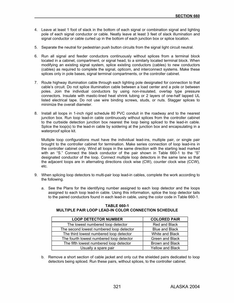
SECTION 660
321 ALASKA 2004
4. Leave at least 1 foot of slack in the bottom of each signal or combination signal and lighting pole of each signal conductor or cable. Neatly leave at least 3 feet of slack illumination and signal conductor or cable curled up in the bottom of each junction box or splice location.
5. Separate the neutral for pedestrian push button circuits from the signal light circuit neutral. 6. Run all signal and feeder conductors continuously without splices from a terminal block
located in a cabinet, compartment, or signal head, to a similarly located terminal block. When modifying an existing signal system, splice existing conductors (cables) to new conductors (cables) as required to complete the signal, opticom, and interconnect systems. Make these splices only in pole bases, signal terminal compartments, or the controller cabinet.
7. Route highway illumination cable through each lighting pole designated for connection to that
cable’s circuit. Do not splice illumination cable between a load center and a pole or between poles. Join the individual conductors by using non-insulated, overlap type pressure connectors. Insulate with mastic-lined heat shrink tubing or 2 layers of one-half lapped UL listed electrical tape. Do not use wire binding screws, studs, or nuts. Stagger splices to minimize the overall diameter.
8. Install all loops in 1-inch rigid schedule 80 PVC conduit in the roadway and to the nearest
junction box. Run loop lead-in cable continuously without splices from the controller cabinet to the curbside detection junction box nearest the loop being spliced to the lead-in cable. Splice the loop(s) to the lead-in cable by soldering at the junction box and encapsulating in a waterproof splice kit. Multiple loop configurations must have the individual lead-ins, multiple pair, or single pair brought to the controller cabinet for termination. Make series connection of loop lead-ins in the controller cabinet only. Wind all loops in the same direction with the starting lead marked with an “S.” Connect the black conductor of the pair shown in Table 660-1 to the “S” designated conductor of the loop. Connect multiple loop detectors in the same lane so that the adjacent loops are in alternating directions clock wise (CW), counter clock wise (CCW), etc.
9. When splicing loop detectors to multi-pair loop lead-in cables, complete the work according to
the following.
a. See the Plans for the identifying number assigned to each loop detector and the loops assigned to each loop lead-in cable. Using this information, splice the loop detector tails to the paired conductors found in each lead-in cable, using the color code in Table 660-1.
TABLE 660-1
MULTIPLE PAIR LOOP LEAD-IN COLOR CONNECTION SCHEDULE
LOOP DETECTOR NUMBER COLORED PAIR The lowest numbered loop detector Red and Black
The second lowest numbered loop detector Blue and Black The third lowest numbered loop detector White and Black
The fourth lowest numbered loop detector Green and Black The fifth lowest numbered loop detector Brown and Black
Usually a spare pair Yellow and Black b. Remove a short section of cable jacket and only cut the shielded pairs dedicated to loop
detectors being spliced. Run these pairs, without splices, to the controller cabinet.

SECTION 660
322 ALASKA 2004
c. Strip the insulation from the ends of the conductors. With the loop and lead-in conductors parallel to one another, twist the bare ends together and then solder them together.
d. Insulate and seal each soldered connection with a mastic lined heat shrink tubing; crimp
the ends of the heat shrink tubing with a pair of needle nose pliers. e. First, crimp and then solder spade terminals to the ends of the shielded pairs in the
controller cabinet. 10. Maintain the electrical isolation between shields and do not allow the drain wires to come in
contact at any point other than the ground bus in the cabinet. Tie all drain wires to the ground bus at the controller cabinet.
11. Encapsulate illumination cable conductor splices in a rigid, 2-piece, transparent, snap
together, plastic mold specifically designed for each splice type. Encapsulate all loop lead-in cable splices in rigid, transparent, PVC molds filled with re-enterable polyurethane electrical insulating and sealing compound. Furnish splice kits rated for 1000 volts AC operation and direct burial. Provide re-useable four piece molds that are held together with stainless steel hose clamps. Two pieces form a cylinder and two flexible end caps seal the ends and allow the conductor entry. Use molds with dimensions suitable for the splice made, encase the cable jackets, and have fill and vent funnels. Insert a loose woven polyester web that allows a full 1/4 inch of insulating compound to flow between the splice and the inside of the mold. Fill the PVC molds with re-enterable polyurethane electrical insulating and sealing compound that cures transparent, is nontoxic, is non-corrosive to copper, and does not support fungi or mold growth.
12. Use molds with dimensions suitable for the splice, to encase the cable jackets, to be rated for 600 volts, and have fill and vent funnels for epoxy resin. Fill the splice mold bodies with epoxy resin that is resistant to weather, aromatic and straight chain solvents, and that will not sustain combustion. When filling the mold bodies of loop lead-in and telemetry cable splices, use a compound that provides re-entry capabilities.
13. Permanently identify all cables and single wire conductors by labeling all pole bases and
cabinets, at each detector loop tail/lead-in cable and illumination cable splices, and in junction boxes adjacent to lighting and signal poles. When modifying an existing system, label all new and existing lighting cables/conductors with circuit numbers at locations noted above. If the existing circuits are not identified, the Engineer will provide the required circuit numbers.
14. Label the cables used in the signal and illumination systems with the following legends:
a. Use the legends included in Table 740-2, for the cables listed.
b. Use the loop number shown on the Plans to label each tail of all loop detectors and the paired loop lead-in conductors in the controller cabinet.
c. For interconnect cables, use the first letter of the direction the cable follows to the
adjacent intersection on each cable. Add a number suffix if more than one cable is routed to the adjacent intersection.
Furnish the two types of identification tags listed below that feature hand written legends. Write the legends specified neatly and legibly, using a black marking pen recommended by
SECTION 660
323 ALASKA 2004
the tag manufacturer. Replace at no expense to the State all identification tags the Engineer deems illegible. a. Use identification cable ties for labeling loop detector tails and the paired conductors
included in each loop lead-in cable in the controller cabinet. Furnish identification cable ties made of nylon that feature a nonmagnetic stainless steel locking device embedded in the head and a tag attached "flag style" to the head. Use cable ties consisting of a single strap with a minimum size tag of 3/4 inch by 3/8 inch.
b. To label all other cables, use cable tags made of nylon reinforced vinyl impervious to the
elements and which will not tear. Provide tags with a 4 inch by 1-3/4 inch minimum size that attach flag style at one corner to a single strap. Furnish yellow tags for labeling all signal and interconnect cables and red tags for labeling lighting and feeder cables.
15. Terminate the control and power cables as shown in Table 740-2. 16. Connect telemetry cable to a Type No. 66B3-50 terminal block. Start the wiring at the top with
Pair No. 1. Connect the incoming cable from the computer to the left side of the terminal block, and connect the outgoing cable to the next intersection to the right side.
17. Wire luminaires using No. 10 AWG illumination tap conductors that run from the fused
disconnect kit in the pole base. Install a fused splice connector between the line and luminaire ballast tap conductors in the base of every pole equipped with a luminaire. Attach the conductors to the connector halves with setscrew type pressure connectors. Provide the plug and socket assembly so that the fuse remains in the load side plug without exposing live metal parts when the connector separates and the coil springs are not included in the current carrying circuit. Make the fused connectors readily accessible from the handhole. Install tap conductors to prevent slack when their ends touch the top of the foundation.
660-3.06 BONDING AND GROUNDING. Make the following mechanically and electrically secure: metallic cable sheaths, metal conduit, non-metallic conduit grounding wire, ballast and transformer cases, service equipment, sign switches, pedestrian push buttons, metal poles, and pedestals. These items must form a continuous system and be grounded. Ground metal conduit, service equipment, and neutral conductor at service point as required by the Code and the serving utility, except that grounding electrode conductor must be No. 6 AWG, or equal. Use copper wire or copper braid bonding and grounding jumpers of the same cross-sectional area as No. 8 AWG for all other systems. When installing conduit as a spare for future use, you may omit the grounding conductor. Furnish threaded-type grounding bushings made of malleable iron or steel with a zinc or galvanized finish. Use bushings with an insulated throat, a tin-plated copper saddle for attaching the grounding conductors, and stainless steel set screws. Retrofit all existing spare conduits that will contain new cables exclusively with new grounding bushings. Whenever you reuse an existing conduit that contains no ground conductor, install a bare size 8 AWG copper wire as the ground conductor. Where conduits are installed for future conductors, the above mentioned copper wire may be omitted. Install a bare copper conductor in all conduit as the grounding conductor. Attach grounding conductors to each end of the metal conduit using insulated throat grounding bushings. Leave 12

SECTION 660
324 ALASKA 2004
inches of slack between each grounding bushing. Allow clearance for bushings when installing conduits in foundations. Bond slip-base type standards and pedestals by using 2 conductors from the conduit, one attached with a ground rod clamp to an anchor bolt and the other connected to the lower portion of the shaft. Bond standards with frangible coupling type bases by attaching one conductor from the conduit to the lower portion of the shaft. Use conductor from the conduit to the shaft that is 48 inches long. Ground one side of the secondary circuit of a transformer. 660-3.07 TRAFFIC CONTROLLER ASSEMBLIES. Prepare each solid-state, traffic controller assembly to operate various traffic signal devices as shown on the Plans. The controller must provide right-of-way, clearance, and other indications using duration and sequence as determined by preset programming. Details of operation for the complete controller assembly must be according to the traffic phases; preferential phase sequence and concurrence; signal indications; signal indication sequence; detection requirements; and other details shown on the Plans or as specified herein. At the time the controller cabinet and equipment are delivered for testing, or if ordered prior to purchase, submit the following for each controller assembly called for in the Plans:
• Two blackline sets of controller cabinet schematic wiring diagrams • Two copies of the manufacturer’s maintenance and operations manuals for the
equipment in the cabinet The schematic wiring diagrams must show all circuits and parts in detail. Clearly identify all parts by name or number. Submit the final wiring diagrams for each controller assembly in an AutoCad Drawing Interchange File format (DXF, DWG, etc.) on 3.5-inch floppy disk. Use only the default font style and line type distributed with a basic AutoCad package. 1. Shop Tests. Deliver the controller units, auxiliary equipment, and fully wired cabinet (including
wiring diagrams and manuals) to a designated test location. All items must arrive together. Partial shipments will not be accepted and will be returned to the vendor. Allow 6 weeks for shop testing. All equipment must meet the operational and functional requirements of the Plans and Specifications when tested according to NEMA Standard TS 1-1989, Traffic Control Systems. If a partial failure occurs at any step in the test (physical, environmental, or operational), you may make on-site repairs within 10 days after notification of the malfunction. The test will then be restarted at the beginning of the category in which malfunction occurred. Failing to make repairs within 10 days after notification will result in rejection. If equipment malfunctions twice in the same category, the equipment will be rejected. When equipment is rejected, return the entire package (including the cabinet) freight collect to the vendor. Submit the new equipment, with a different serial number, for testing. Do not use rejected equipment on signal projects within the State of Alaska. Testing after equipment rejection for failure to comply with specification requirements will be at your expense. The Department will make deductions to cover the costs of such testing from any moneys due or which may become due to you under this Contract.

SECTION 660
325 ALASKA 2004
A failure is any occurrence that results in other than normal equipment operation. The equipment is considered to have failed if any of the following occur:
• The controller unit malfunctions • The load switch produces incorrect signal indications • The signal conflict monitor fails to satisfy the contract requirements
After the shop test is satisfactorily completed, you will be notified to pick up the tested and marked equipment at the test site. Pick up the successfully tested equipment within 2 weeks of notification and deliver to the work site. Successful test completion does not relieve you of equipment warranty obligations as specified in Subsection 660-2.01.3 or field testing as specified in Subsection 660-3.01.7. Copies of shop test results will be sent to you, the vendor, and the State Materials Engineer.
2. Controller Cabinet Installation.
a. Where the cabinet is mounted on a concrete pedestal foundation, place a 1-inch drain hole or pipe with screen in the foundation, connecting to the cabinet and emptying above the ground line.
b. Place a 3/8-inch fillet of silicone caulking between each controller cabinet and the
concrete slab foundation to prevent dust and dirt from entering the cabinet.
c. When called for in the Plans or Special Provisions, add 2 inches of approved foam insulation within the bottom of the cabinet between the control equipment and the concrete base. Design all wiring, terminals, and other items to allow sufficient room for the insulation.
d. On Precast Controller Foundations. When called for in the Plans or Special Provisions,
place a 3/8-inch thick, 2-piece exterior grade plywood board on the bottom of the cabinet and under the foam insulation. Place the plywood within the controller cabinet, and do not extend under it. Make holes to allow for the conduits entering the cabinet. Place a pliable sealant composed of a silicon caulking compound between the plywood board and the cabinet and between the plywood board and all the conduits.
e. Place a ground rod in the Type III junction box next to the cabinet or in the foundation of
the cabinet if it is precast foundation. f. See Subsection 660-3.05 and Section 740 for wiring requirements.
3. Controller Operation. Provide the following operations.
a. Wire the controller cabinet to flash the yellow signals on the main street or highway, and the red signals on the cross streets and left turn lanes.
b. Make the flashing circuit independent of the controller unit. They must remain in
operation upon shutdown of the controller or removal of the controller from the cabinet.
c. Wire the controller cabinet so that removal of the conflict monitor causes the intersection to go into flashing operation.
d. Accomplish transfer to flashing operation by relays between the normal load switching
device and the field terminals.
e. Do not operate pedestrian pushbuttons at more than 24 volts.

SECTION 660
326 ALASKA 2004
f. Controller Priorities. Prioritize the drives, controls and equipment so that each device, control, or item of equipment overrides the operation of those items listed below it: (1) Power failure (2) Power restart (3) Flashing (4) Railroad preemptor (5) Emergency vehicle preemptor (6) Phase selector (7) Interconnect (8) Time switch (9) Normal controller unit operation
Provide the following preemption operations when called for on the Plans or as specified in the Special Provisions. a. General. Preemption units must use the controller unit functional inputs and timings to the
largest extent possible. Signal load switching control must remain with the controller unit.
b. Railroad Preemption. The Railroad Preemption Routine must consist of 4 functional intervals in the order listed below:
(1) Enter Preemption Interval.
(a) Energize a 120 VAC alarm circuit which may be used for a sign, bell, or beacon. (b) Immediately advance to the pedestrian clearance interval of any walk that is
being displayed. On any phase other than the track clearance phase(s), abbreviate the pedestrian clearance interval by a timer with a minimum range of 0-30 seconds.
(c) Following the pedestrian clearance period, the controller must advance into and time normally the vehicle clearance intervals.
(d) If the preemption is received while in the track clearance phase(s), skip step (b) and (c) above.
(2) Track Clearance Interval.
(a) Provide a timing period to allow sufficient green clearance time for any vehicles that may be stopped on or immediately behind the railroad tracks. The timing must be adjustable over a range of 0 to 30 seconds.
(b) Following the track clearance period, the controller must advance into and time normally the vehicle clearance interval(s).
(3) During Preemption Interval. Allow the controller to operate normally with the
exception of not serving those phases that conflict with the railroad crossing. Keep this interval in effect until the preemption call is removed.
(4) Leaving Preemption Interval.
(a) De-energize alarm circuit. (b) Immediately advance to the active phase normal pedestrian and/or vehicle
clearance interval(s). (c) The controller must advance to those phases that were omitted under
preemption control when complete control is returned to the controller unit.
c. Emergency Equipment Preemption. The Emergency Equipment Preemption Routine must consist of 3 functional intervals in the order listed below:

SECTION 660
327 ALASKA 2004
(1) Enter Preemption Interval.
(a) Energize a 120 VAC alarm circuit which may be used for a sign, bell, or beacon. (b) Immediately advance to the pedestrian clearance interval of any walk that is
being displayed. On any phase other than the track clearance phase(s), abbreviate the pedestrian clearance interval by a timer with a minimum range of 0-30 seconds.
(c) Following the pedestrian clearance period, the controller must advance into and time normally the vehicle clearance intervals.
(d) If the preemption call is received while in the preempt phase(s), skip step (b) and (c) above.
(2) Preempt Phase Interval. Hold the controller in the preempt phase(s) until the call is removed.
(3) Leaving Preemption Interval. When the preemption call is removed, the controller unit
must immediately revert to normal operation.
660-3.08 SIGNAL AND LIGHTING STRUCTURES. Install signal and lighting equipment according to the details shown on the Plans and the following: Remove all burrs and sharp edges from inside and outside of all holes before passing conductors through the walls of posts, poles, mast arms, signal heads, and other equipment. Install photoelectric control units to face the north sky. When installed on the top of steel poles, install the bracket in the center of the rain cap. Secure it with a locknut and make watertight with a fillet of silicone caulking compound. When installed on wood poles or Type 1 or 1A Load Centers, couple the bracket to the end of a rigid metal conduit. 1. Electrolier Installation. Before installation, check the socket position in the luminaire to verify
that it corresponds to the setting indicated in the instructions for the light distribution type shown on the Plans. Set the pole with a slight rake, by plumbing the side of the tapered pole away from the road. After the pole has been plumbed, level the luminaire as recommended by the manufacturer.
2. Wood Pole Installation. Place the poles in the ground to at least 6 feet deep. After setting each wood pole in the ground, backfill the space around the pole with selected earth or sand, free of rocks 4 inches or larger, or deleterious material. Place in layers approximately 4 inches thick and thoroughly compact with mechanical tampers. Provide overhead equipment a minimum vertical clearance of 18 feet from bottom of equipment to the pavement.
3. Signal Pole Installation. Install signal poles with the centerline of the pole plumb. Provide a 1-inch drain hole in the grouted base. Run this drain from below the top of the conduits to outside of the grouted area.
4. Signal Head Mounting. Support bracket mounted signal heads, as shown on the Plans, by mounting brackets consisting of watertight assemblies of 1-1/2 inch nominal diameter standard steel pipe and malleable iron or brass pipe fittings. All members must be either plumb or level, symmetrically arranged, and securely assembled. Construct these so that all conductors are concealed within the assembly.

SECTION 660
328 ALASKA 2004
Attach vehicle and pedestrian signal head mounting hardware to the side of pole that faces away from traffic. Aim through-phase vehicle signal faces at a point located a distance from the face as shown in Table 660-2. If 2 through-signal faces are not visible from this point at a height of 42 inches above finished grade, consult the Engineer for corrective measures. Direct pedestrian signal heads at the center of the crosswalk on the opposite side of the street.
TABLE 660-2 THROUGH-SIGNAL AIMING POINT
85th Percentile Speed
(mph) Minimum Visibility Distance
(feet) 20 175 25 215 30 270 35 325 40 390 45 460 50 540 55 625 60 715
The horizontal dimension between the center of a terminal compartment or axis of a signal face and the axis of an immediately adjacent signal face must be a minimum of 22 inches in side mounted frames and 11 inches in post top installations. At each signal location, construct a terminal compartment into the mounting brackets. Fit each compartment with a terminal block containing 12 poles, each with 2 screw-type terminals. Each terminal must accommodate at least 3 No. 14 AWG conductors. Provide a rain-tight cover, giving ready access to the terminal block. Provide a bronze terminal compartment of sufficient strength to remain intact in event the pole is knocked down. Provide cast-iron slip-fitters, where used without integral terminal compartment. For post-top mounting of bracket mounted signals, cast the terminal compartment with an integral slip-fitter. For post-top mounting of a 1 way signal head, you may use a slip-fitter without a terminal compartment. The slip-fitter must fit over a 4-inch standard pipe or 4-1/2 inch outside diameter end of tapered standard. Provide each slip-fitter with 2 rows of cadmium plated steel set screws, with 3 screws in each row to secure the assembly in plumb position. Where signal heads are side mounted on poles, the terminal compartment must be designed for and securely bolted to the pole. Mount pole side mounted pedestrian and traffic signal heads on the back side of pole unless noted or detailed otherwise on the Plans. Mount the pole/post mounted traffic signal heads so that no portion of the backplates are hidden by the pole/post. Equip the signal heads with positive brass lock rings and fittings designed to prevent heads from turning due to external forces. Lock ring and connecting fittings must have serrated contacts.

SECTION 660
329 ALASKA 2004
Equip signal head assembly for suspension from mast arm with a ferrous or bronze plumbizer. Do not mount signal heads within 12 inches either side of a mast arm extension splice. Do not install signal heads at any intersection until all other signal equipment, including the controller, is in place and ready for operation at that intersection, unless the faces are not directed toward traffic or unless the faces are adequately covered. Side-mount pedestrian signals using a 2-piece, hinge connected, cast aluminum bracket that mounts directly between the pole and the side of the signal head housing. Limit clearance between the head and pole to 3 inches. The bracket must properly fit round poles 4 inches or greater in diameter and allow a minimum rotation of 30 degrees when mounted on a 4-inch pole. Include a rain-tight 12-position terminal block within the mounting bracket.
5. Pedestrian Push Button Installation. Install the push button and sign on the crosswalk side of the pole. Install indicator lights when specified. Pedestrian push button signs must conform to the details in the ASDS. Install push button signs and The Meaning of Pedestrian Signals stickers, R9-4, above each push button. Use R10-4B (R or L) push button signs with the arrow pointing in the direction of the appropriate crosswalk. Install the sticker immediately above the push button and below the sign. When channel is used for mounting push button signs, tap the top and bottom sign bolts into the pole.
6. High Tower Lighting System Installation. Install the high tower poles as recommended by the manufacturer. Provide the erection plan to the Engineer prior to installing poles. Attach the luminaire to the bracket arm by means of a bracket entry and lamp support assembly. Install the lowering system including head frame, luminaire support ring, winch(s), hoisting assembly, and electric motor. Adjust the luminaire reflectors until all are oriented in the same direction and they provide the asymmetrical light distribution pattern shown on the illumination sheets.
7. Underpass Lighting System Installation. Mount the fixture as detailed on the drawings so that the axis of the lamp is perpendicular to the axis of the underpass.
8. Flashing Beacon Installation. When installing flashing beacons adjacent to or in conjunction
with a traffic signal system, install the flasher control in the controller cabinet. 660-3.09 MAINTAINING TEMPORARY AND EXISTING ELECTRICAL SYSTEMS. Keep in effective operation during the progress of the work all existing electrical systems (traffic signal, highway and street lighting, flashing beacon, and sign illumination), and approved temporary replacements except when shutdown is permitted to allow for alterations or final removal of the systems. Temporary replacement equipment must be compatible with existing equipment used in the Region. Limit traffic signal shutdowns to the period Sunday through Thursday between the hours of 9:00 p.m. to 6:00 a.m., unless otherwise specified in Subsection 643-3.08. Do not allow lighting system shutdowns to interfere with the regular lighting schedule. Obtain written approval before performing any work on existing systems. Notify the local traffic enforcement and maintenance agencies at least 24 hours before the operational shutdown of a traffic signal system. Provide necessary traffic control under Section 643.

SECTION 660
330 ALASKA 2004
Where an existing system is being modified, the Department will pay for work not shown on the Plans or Special Provisions that is considered necessary to keep all or part of the existing system in effective operation as extra work as provided in Subsection 109-1.05. Once commencing work on the project, provide all maintenance for temporary and existing electrical facilities. The State will pay for the electrical power for the above mentioned electrical systems. The above maintenance does not include previous damage such as burned out lamps, non-operative detection, or other malfunctioning equipment. Present written documentation of all non-functioning and malfunctioning electrical equipment before commencing work on the project. You and the Engineer will inspect this equipment jointly. If work begins on the Project and the Engineer does not receive written notice, this is considered evidence that all equipment is functional and operational. Give the Engineer the name and 24-hour phone number of the person maintaining the existing and temporary electrical facilities. Commence repair work within 1 hour of notification for traffic signal systems. Ascertain the exact location of existing conduit runs, direct burial cable, junction boxes, and all underground utilities before using equipment that may damage such facilities or interfere with any system. Where roadways are to remain open to traffic and existing lighting systems are to be modified, complete work each day so the lighting system will be in operation by sunset. When you work on a traffic signal system, keep a record of all work performed in a diary located in the controller cabinet. Furnish a diary for each temporary system. Make sure each entry is printed legibly and includes: 1. The dates and times you began and completed your work, and the names of the
crewmembers completing the work.
2. The characteristics of the equipment failure or faulty operation evident before repair.
3. The changes made or corrective actions taken.
4. The printed name and signature of the person responsible for making the repairs or changes. Keep temporary electrical installations in effective operation until they are no longer required. Salvage all original and Department-provided equipment according to the provisions in Subsection 660-3.01.6 and remove all other materials from the project. 660-3.10 FALSEWORK LIGHTING. When required by the Special Provisions, install falsework lighting where vehicular traffic with or without pedestrian traffic crosses through or under structure falsework. Provide illumination of the portal faces of falsework during the hours from dusk to dawn. Provide illumination of the pavement and pedestrian openings through or under falsework 24 hours a day. Submit a plan for the proposed lighting installations and do not commence falsework construction until the Engineer has reviewed such plans. The Engineer will make a subsequent review after you place falsework lights in operation. Falsework lighting equipment remains your property and must be removed from the site of the work upon completion of the project or when directed.

SECTION 660
331 ALASKA 2004
660-4.01 METHOD OF MEASUREMENT. Section 109 and the following: Item 660(9), Bored Casing. By the linear foot along the slope of the bored or jacked casing for the actual length bored or jacked, in place. Item 660(11), Traffic Loop. By each loop unit, complete and in place, including all conduit, conductors, and other equipment to the nearest junction box. Item 660(13), Relocate Electrolier. By each complete unit, removed, relocated, reinstalled, and functional. 660-5.01 BASIS OF PAYMENT. Sign removal and reinstallation required to install foundations, conduits, and junction boxes is subsidiary. Minor conduit routing changes as directed are subsidiary to existing contract pay items. All concrete required to complete the foundations is subsidiary. If no item for Bored Casing is included in the bid schedule, boring is subsidiary to other items of work. If the Engineer orders soffit lights or lighting for pedestrian structures placed in operation before permanent power service is available, the Department will pay the cost of installing and removing temporary power service as extra work under Subsection 109-1.05. Furnishing, installing, maintaining (including power), and removing falsework lighting is subsidiary to the items of work involved in the structure that requires the falsework lighting. Payment will be made under:
Pay Item Pay Unit 660(1) Traffic Signal System Complete Lump Sum 660(2) Flashing Beacon System Complete Lump Sum 660(3) Highway Lighting System Complete Lump Sum 660(4) Sign Illumination System Complete Lump Sum 660(5) Structure Illumination System Complete Lump Sum 660(6) Traffic Count System Complete Lump Sum 660(7) Temporary Signal System Complete Lump Sum 660(8) Temporary Illumination System Complete Lump Sum 660(9) Bored Casing __Inch Minimum Diameter Linear Foot 660(10) High Tower Lighting System Complete Lump Sum 660(11) Traffic Loop Each 660(12) Underpass Lighting System Complete Lump Sum 660(13) Relocate Electrolier Each

332 ALASKA 2004
SECTION 661
ELECTRICAL LOAD CENTERS
661-1.01 DESCRIPTION. Furnish and install load center assemblies at the locations indicated in the Plans. Modify existing load centers when indicated. Use load centers of the following types as shown on the load center detail sheets:
Type 1: Pad mounted with underground service (large) Type 1A: Pad mounted with underground service (small) Type 2: Post mounted with underground service Type 3: Pole mounted with overhead service
661-2.01 MATERIALS. Use materials that conform to Section 740, the Materials Certification List, the Plans, specifications, and the following.
Concrete Section 501 (Class A) Grout Subsection 701-2.03 Reinforcing Steel Section 503
Wood Posts. Construction grade, 6 x 6 inch nominal dimension S4S Douglas Fir, Hem-Fir, Western Larch, Western Hemlock, Mountain Hemlock or Southern Pine meeting Standard Grading and Dressing Rules, West Coast Lumber Inspection Bureau. Treat the posts according to Section 714. Load Center. NEMA 3R enclosure constructed of zinc-coated A60 finish sheet steel per ASTM A 653 and ASTM A 924, with no external screws, bolts, or nuts. Shop coat cabinet components with a 2-part urethane paint undercoat and 2-part urethane finish coats. Finish coats must be standard white for removable panels and non-gloss silver-gray, closely matching FSS No. 5950 Color No. 36622, for the enclosure. The load center must be labeled as a unit by an approved independent electrical testing laboratory (such as UL, ETL, CSA, etc.) defined by ANSI Standard Z34.1 Third-Party Certification Programs for Products Processes and Services and conform to applicable published standards noted herein, the Plans, and Special Provisions. The load center must be labeled as service entrance equipment. Panelboards. Load panels in load centers must conform to FSS W-P-115C, Type 1 - Circuit Breaker Panelboards; UL 67 - Panelboards; and NEMA PB1 - Panelboards with Molded Case Circuit Breakers. The rated voltage of the panels must be as noted on the load center summary in the Plans, 120/240 volts or 240/480 volt single phase or 120/208 volt or 277/480 volt three-phase. The ampacity rating of panels must not be less than the ampacity noted on the load center summary, 100 amps minimum, at rated voltage. Circuit Breakers. Use bolt-in type circuit breakers with a copper bus. Provide separate neutral and ground busses. The series rated interrupting capacity of the circuit breakers in the panels must not be less than shown on the load center summary, or 10,000 AIC minimum, at rated voltage. Use circuit breakers that are molded-case thermal-magnetic types with single-trip indicating switch handle. They must have an enclosed toggle type operating mechanism with quick-make/quick-break action and have a trip-free disconnect from the switch handle that will prevent the contacts from being held in the closed position. The circuit breakers must have the frame size, interrupting capacities, and trip rating clearly marked on the breaker. Multi-pole circuit

SECTION 661
333 ALASKA 2004
breakers must have a common trip mechanism. Contacts must be silver alloy enclosed in an arc quenching chamber. Overload trip ratings must be self compensating for ambient temperatures from 14 °F to 140 °F. Circuit breakers must be 240 or 277 volt maximum rated for 120/240/277 volt circuits, which ever is applicable, and have an interrupting capacity (RMS - symmetrical) of not less than 10,000 amperes. They must have not less than 480 volt rated for circuits above 277 volts and have an interrupting capacity (R.M.S.- symmetrical) of not less than 14,000 amperes. Contactor. Electrically-held type consisting of an operating coil, a laminated armature, contacts, and terminals. Contacts must be fine silver, silver alloy, or superior alternative material rated to switch the specified load, 30 ampere minimum at rated voltage, and be normally open, unless otherwise noted. Contactor coils must be rated for operation at 240 VAC. Meters. Equip all meter sockets mounted in Type-1 and Type-1A load centers with internal mounted meters with manual circuit closing devices. The devices may be either the link or lever type. Do not use the horn and sliding types. Equip all load centers with internal mounted meters with safety sockets (that is, provisions for de-energizing the meter jaws). The test section cover must be sealable with a 0.047-inch stainless steel bail. Transformers. Transformers in load centers containing load panels of different nominal voltages must be isolated winding type with primary and secondary voltages and KVA ratings as noted on the Plans. Transformers must carry rated volt amperes continuously without exceeding a 240 °F temperature rise above a 100 °F ambient temperature. Where installed outside of the load center enclosure, use a non-ventilated transformer fabricated from aluminum, stainless steel, or galvanized steel and filled with high-melting point, thermal setting, or epoxy insulating compounds to prevent moisture from entering the winding enclosure. Coat enclosures fabricated from sheet metal with moisture-resistant paint. Insulate transformer leads with non-hygroscopic material and extend them 9 inches beyond the winding chamber seal. Conductors. Stranded copper with either type XHHW-2 or RHW insulation. Conduit. Galvanized rigid conduit made of mild steel meeting UL standard UL-6. Terminals. Size all terminals according to the amperage ratings of the conductor used. They must be suitable for termination of copper and aluminum conductors. Photoelectric Controls. Use photoelectric controls rated for operation at 240 VAC. Galvanizing. Galvanize steel materials according to Subsection 716-2.07. Repair damage to galvanized coatings per AASHTO M 36. Welding. Perform welding according to Subsection 504-3.01, and the requirements of the individual items. Equipment List(s) and Drawings. Within 30 days after the Contract award, submit 8 collated copies of a portfolio of equipment and materials proposed for installation to the Department for review and approval. Include a table of contents in the portfolio(s) that includes each item’s intended use(s) and the following: 1. Materials on the Approved Products List: A description that includes product name,
manufacturer, model or part number, and the conditions listed for approval. 2. Materials Not on the Approved Products List: Catalog cuts that include the manufacturer’s
name, type of product, size, model number, conformance specifications, and other data as may be required, including manufacturer’s maintenance and operations manuals, or sample articles.

SECTION 661
334 ALASKA 2004
3. Materials Not Requiring Certification: Incidental materials incorporated into the work (such as
nuts, ties, bolts, washers, etc.) must meet all applicable Specifications and be installed per all manufacturer’s recommendations. Certification is not needed unless required by the Special Provisions or requested by the Engineer.
661-3.01 CONSTRUCTION REQUIREMENTS. Install load centers at the location and position shown on the Plans. Any deviation from the plan location must be coordinated with and approved by the serving utility and the Engineer. Furnish conduit, conductors, contactors, breakers, transformers, and all other necessary materials at all new and modified load centers to complete the installation. Install a rigid metal conduit of the size shown in the Plans at a 30-inch depth from the load center and extend it to a location 2 feet from the power source. Install a pull rope in the conduit, cap the end, and mark the terminus with a 2- x 4-inch stake or 1-inch rebar, 3 feet long. Extend the end of the stake or bar 1 inch above the ground. When the servicing utility requires the complete conduit and weather head to be in place on the designated service pole, furnish and install all materials required by the utility. The additional work and materials are subsidiary to the load center bid item. Where the service is to be installed on a utility-owned pole, coordinate the positioning of the riser and service equipment with the service utility. House circuit breakers, switches, and contactors in a NEMA 3R type enclosure listed by an approved independent electrical testing laboratory as service equipment with a hinged and locking front cover. Indelibly label panel covers with the circuit number. Legend plates, labels, and signs must be engraved plastic or metal fastened with screws, non-cold-susceptible adhesive, or component mounting hardware. Size and wire load center cabinets to serve the combination of highway lighting, traffic signal, and thaw wire circuits shown in the Plans. Each cabinet must be a single box subdivided to form compartments as required. Include hinged lockable door(s) or panel cover(s) with provision for a padlock with a 5/16 inch diameter shackle for each compartment. Circuit breaker ratings must be as shown in the load center summary for each location. Wire and equip load centers with commonly metered thaw wire and lighting circuits with separate contactors, selector switches, and terminal blocks for lighting and thaw wire circuits. Control the thaw wires as described in Section 616. Where a meter is required, furnish and install a meter socket that is acceptable to the serving utility, complete with sealing rings. Do not mount the meter socket on doors or removable panels. Load centers containing contactors must have contactor control switches mounted in the load distribution section. Control switches for systems having automatic controls (for example, photo cell, thermostats, or time controls) must be 3-position types with the positions labeled “On”, “Off” and “Auto”. Control switches for manual control only must be a 2-position type with positions labeled “On” and “Off”. Label each switch to identify function being controlled. Mount transformer fuses in dead-front fuse holders with lighted blown fuse indicators, where required. Label them to indicate function and fuse amp rating. Install a 3/4-inch x 10-foot copper clad ground rod inside the base readily accessible thru the removable cover, or adjacent supporting post. Connect ground rod to neutral bus with a soft-drawn copper conductor sized per NEC, No. 6 AWG minimum. Bond all non-current carrying metal parts of the load center to the ground bus.

SECTION 661
335 ALASKA 2004
Locate the photo cell for lighting control on the nearest light standard or top of the load center as shown on the load center summary. Orient it to the unobstructed northern sky. Submit for approval the method of attachment of the conduit to the load center. Use a 5-conductor No. 14 AWG wire to connect the photo cell to the load center. When the photo cell is on a lighting standard with a slip base or frangible coupling style base, use an approved break-away disconnect in the base of the light standard. Restrain the cable in a similar manner as the lumination cable in the pole base. Provide a typed circuit directory for each load panel inside of the load center door, protected with a plastic cover, describing each circuit, with even and odd numbered circuit breaker positions shown on separate parts of the directory. Provide a power and control one-line diagram protected by a laminated plastic cover inside the load center. Include the following information on the directory and one-line diagram: Load center identification (A, B, etc.), Project Name, Project number (Federal/State) and Service Voltage. 661-4.01 METHOD OF MEASUREMENT. By the actual number of load centers, modified load centers, and transformers completed and accepted shown on the Plans or as directed. 661-5.01 BASIS OF PAYMENT. Load circuits, consisting of conduits and conductors attached to the load centers and photoelectric controls, and terminations of field wiring, are subsidiary to other items of work. Payment will be made under:
Pay Item Pay Unit 661(1) Load Center, Type 1 Each 661(2) Load Center, Type 1A Each 661(3) Load Center, Type 2 Each 661(4) Load Center, Type 3 Each 661(5) Modify Existing Load Center Each 661(6) Transformer, ____ KVA Each

336 ALASKA 2004
SECTION 670
TRAFFIC MARKINGS 670-1.01 DESCRIPTION. Furnish and place traffic markings of the type, color, dimensions, and at the locations shown on the Plans. Meet these specifications and the applicable portions of the Alaska Traffic Manual. 670-2.01 MATERIALS. Use materials that conform to the following:
Traffic Paint Subsection 708-2.03 Glass Beads Subsection 712-2.08 Preformed Pavement Markings Subsection 712-2.14 Raised and Recessed Pavement Markers Subsection 712-2.15 Methyl Methacrylate Markings Subsection 712-2.17 Glass Beads for Methyl Methacrylate Markings Subsection 712-2.18
Construct the iron casting for the raised pavement markers of modular iron meeting ASTM A 536. Submit a manufacturer certification for both the Methyl Methacrylate material and glass beads to certify that the materials furnished conform to these Specifications. 670-3.01 CONSTRUCTION REQUIREMENTS. Install interim pavement markings meeting Section 643 if permanent markings are not installed prior to opening the roadway to traffic. 1. Paint.
a. Apply paint only to pavements that are clean, dry, and warmer than 40 °F. b. Remove all dirt, oil, grease, and other foreign matter from the surfaces to be painted in a
satisfactory manner. c. Apply the paint at the rate of 80 ft2/gal (approximately 20 mils wet film thickness). This
rate is effectively 22 gallons of paint per mile of solid 4-inch stripe. A tolerance not to exceed 10% is allowed for film thickness or yield.
d. Apply glass beads over the wet painted stripes in a uniform pattern at the rate of 6
pounds (± 0.1 pound) of beads per gallon of paint. Pressure-apply the beads using a mechanical dispenser mounted not more than 12 inches behind the paint dispenser.
e. Use approved equipment for highway lane striping that is specifically designed and manufactured for that purpose by a company experienced in the design and manufacture of such equipment. Minimum requirements include the capability of striping two 4-inch yellow centerlines and one 4-inch white edge line simultaneously. Apply markings with clear-cut edges, true and smooth alignment, and uniform film thickness.
2. Preformed Marking Tapes (PMT). Apply the PMT material as directed by the manufacturer by
either the inlay or overlay method. Use the inlay method whenever new asphalt concrete is placed. Use the overlay method to apply markings to existing pavement.
Store all PMT materials between 60 °F and 85 °F for at least 24 hours prior to installation. During installation, maintain field stockpiles at the required storage temperature. For the inlay method, embed the pavement markings in the asphalt concrete surface with a conventional steel wheeled roller. Apply when the surface temperature of the mat is the
SECTION 670
337 ALASKA 2004
warmest possible without deforming the marking. The minimum allowable surface temperature, taken within 3/8 inch of the top of the mat, is 140 °F.
If the application of the PMT materials falls behind the paving operation to the extent that the markings are not being applied at the minimum acceptable temperature, slow the paving operation to match the rate of the marking laydown. Resume full paving operations after demonstrating that you have sufficiently skilled personnel to install the markings within the required temperature limits. When applying pavement markings by the overlay method, ensure the surface is clean and dry and is at least 60 °F and rising. Broom the surface clean. Remove any dust using compressed air. Apply a coat of primer/adhesive activator according to the manufacturer’s recommendations. Install and roll the markings with a minimum 200-pound pneumatic roller.
3. Raised and Recessed Pavement Markers. Install raised and recessed pavement markers per
the manufacturer’s instructions.
Cut or dado the finished pavement surface with a concrete saw to produce a slot with dimensions as shown on the Plans or recommended by the manufacturer. Clean and dry the slots using compressed air. Install a reflective marker of the color indicated with an epoxy adhesive recommended by the marker manufacturer.
4. Methyl Methacrylate Pavement Markings.
a. General. Provide installation instructions for the methyl methacrylate markings a minimum of 15 days prior to application. Retain a copy of the instructions for use on the project. Ensure the on-site presence of a manufacturer's representative on the first day of striping and any additional days as required.
b. Preparation. Prepare the roadway areas to receive methyl methacrylate pavement markings according to the manufacturer's recommendations. Clean and dry roadway surface. Remove contaminants such as curing agents, surface oils, or existing road marking materials prior to applying pavement marking material. Do not apply marking to new asphalt until the asphalt has cured for at least 15 days.
c. Application. Apply methyl methacrylate marking material according to the manufacturer's
installation instructions and the recommendations of the manufacturer's representative. Use equipment designed and capable of properly mixing at the point and time of application. (1) Longitudinal Markings. Apply markings for lane lines, edge lines, and centerlines at a
thickness of 60 ± 5 mils. Apply glass beads at the drop rate specified in Subsection 712-2.18 by double bead gun, one gun directly in front of the spray unit and another directly behind.
(2) Transverse Markings. Apply markings for crosswalks, stop bars, symbols, transverse
markings between gore and channelization striping, and legend markings at a thickness of 120 ± 5 mils. Apply Sinker beads as specified in Subsection 712-2.18 at a minimum drop rate of 1 lb/yd2.
d. Sampling. Collect a representative sample of spray material by placing a flat sheet of
aluminum in the path of the striping guns. Collect the sample without glass beads. Measure the thickness of the sample without glass beads utilizing a wet film thickness gage.
SECTION 670
338 ALASKA 2004
670-3.04 PAVEMENT MARKING REMOVAL. Remove all existing traffic markings that are in conflict with the striping details shown on the Plans, an approved TCP, or any temporary striping as directed. Do not paint over existing markings. Do not use open flame on the final paving lift. Remove pavement markings to the fullest extent possible without materially damaging the pavement surface, color, or texture. As the work progresses, remove sand or other material deposited on the pavement as a result of removing markings. Remove accumulations of sand or other material that might interfere with drainage or constitute a hazard to traffic. Before making any change in the traffic pattern, remove or obliterate pavement markings that may create confusion to motorists. Where using blast cleaning to remove pavement markings or objectionable material within 10 feet of a lane occupied by public traffic, immediately remove the residue (including dust) after contact between the sand and the surface being treated. For such removal, use a vacuum attachment operating concurrently with the blast cleaning operation or by other approved methods. Repair any damaged pavement or surfacing caused by the pavement marking removal operation. 670-3.05 PRELIMINARY SPOTTING. Provide the necessary control points at intervals including all changes of direction and changes in the basic configuration of striping, such as at the beginning and ending of no-passing zones on a 2-way, 2-lane roadway. Use these points in preliminary spotting of lines before striping is commenced. Perform preliminary spotting of the lines to be painted and obtain approval for all spotting before striping begins. Preliminary spotting is required for all longitudinal striping, with spacing of spots not to exceed 50 feet. Reference the lines and markings to be replaced at their existing locations prior to performing any work that may disturb them. 670-3.06 TOLERANCES FOR LANE STRIPING. 1. Length of Stripe. ±6 inches in 40 feet 2. Width of Stripe. ±1/4 inch 3. Lane Width. ±4 inches from the widths shown on the Plans (measured from the edge of
pavement or edge of traveled way to center of lane line or between the centers of adjacent lane lines)
4. Stripes on Tangent. Do not vary more than 1 inch laterally within a distance of 100 feet when
using the edge of the stripe as a reference. 5. Stripes on Curves. Uniform in alignment with no apparent deviations from the true curvature 6. All Stripes. Keep the center of the stripe within 4 inches from the planned alignment. Traffic markings not within the above tolerances are unacceptable under Subsection 105-1.11. 670-4.01 METHOD OF MEASUREMENT. Section 109 and the following: 1. Mile Basis. By the horizontal distance along centerline from beginning to end of each stripe
pattern, excluding gaps for intersections or other openings. Skip stripes will be measured as 1/4 of this distance.

SECTION 670
339 ALASKA 2004
a. Single Stripe: A longitudinal marking less than 6 inches wide, such as, but not limited to, a single center line or edge stripe.
b. Double or Wide Stripe: A longitudinal marking greater than 6 inches wide, such as, but
not limited to, double center lines, and auxiliary lane lines. 2. Square Foot Basis. Transverse pavement marking lines 6 inches or more wide will be
measured by nominal width times actual length. 3. Each. All other transverse markings will be measured on a unit basis with each separate
word or symbol constituting a unit.
Raised or recessed pavement markers will be measured per each unit installed complete. 670-5.01 BASIS OF PAYMENT. At the contract price per unit of measurement for those items listed below that appear on the bid schedule. Accept payment as full compensation for cleaning of pavement, painting traffic markings, application of preformed pavement markings, glass beads, installing raised or recessed pavement markers, furnishing paint, glass beads, preformed marking tape and all other materials necessary to complete the work prescribed in this Section. When Item 670(9) Removal of Pavement Markings is not shown on the bid schedule, it is subsidiary to other items of work. For traffic markings which do not conform to the requirements of this Section but which are allowed to remain in place, payment will be adjusted as follows: 1. Lump Sum. When payment is on a lump sum basis the price reduction will be the product of
the lump sum price times the length of non-conforming markings divided by the total length of markings. For the purpose of this calculation, stripe lengths will be considered as continuous with no deduction for skips or breaks, for each 4-inch width stripe being applied, except that a double centerline stripe (No Pass) will be considered as one stripe.
2. Unit Prices. When payment is on a unit price basis, no payment will be made for those units
which are not in conformance. Payment will be made under:
Pay Item Pay Unit 670(1) Painted Traffic Markings Lump Sum 670(2) Single Stripe Mile 670(3) Double or Wide Stripe Mile 670(4) Transverse Pavement Marking Lines Square Foot 670(5) Transverse Markings, Words and Symbols Each 670(6) Preformed Pavement Markings Lump Sum 670(7) Raised Pavement Marker Each 670(8) Recessed Pavement Marker Each 670(9) Removal of Pavement Markings Mile 670(10) Methyl Methacrylate Pavement Markings Lump Sum 670(11) Methyl Methacrylate Transverse Pavement Marking Lines Square Foot 670(12) Methyl Methacrylate Transverse Markings, Words and Symbols Each
340 ALASKA 2004
DIVISION 700 -- MATERIALS
SECTION 701
HYDRAULIC CEMENT 701-1.01 GENERAL. Meet the following general requirements for all cement furnished: Provide product from only one mill for any brand and type of hydraulic cement except to reduce excessive air entrainment when using air-entraining cement. Cement may be shipped from pretested approved bins. Before using, retest cement that has been stored longer than 60 days in unsealed bins or silos. Store separately different types or brands of cement, or cement from different mills. Protect cement from dampness during shipment and storage. Do not use partially set cement or cement which contains caked lumps. Do not use cement salvaged from discarded or used bags. 701-2.01 PORTLAND CEMENT. Meet AASHTO M 85, Type I, II, or III, including the low-alkali cement requirement shown in Table 2. 701-2.02 BLENDED HYDRAULIC CEMENT. Meet AASHTO M 240, Type IP (Portland-pozzolan cement), modified as follows: 1. Cement constituent: meet Subsection 701-2.01. 2. Pozzolan constituent: fly ash meeting Subsection 711-2.03 and constituting between 15%
and 20% (by weight) of the blended cement. 3. Furnish a certificate of compliance meeting AASHTO M 240, Section 14 as required by
Subsection 106-1.05. 701-2.03 GROUT. Non-shrink, non-corrosive, non-metallic, cement-based grout meeting ASTM C-1107, Grade C. Meet the requirements of ATM 520. Develop a 28-day compressive strength of 9,000 psi.

341 ALASKA 2004
SECTION 702
ASPHALT MATERIALS 702-2.01 ASPHALT CEMENTS. Meet AASHTO M 320 and the following:
ADDITIONAL REQUIREMENTS FOR PERFORMANCE GRADED ASPHALTS
PG 58-28 PG 64-28 Softening Point, min. (AASHTO T 53) 120 oF 125 oF Toughness, min. (ASTM D 5801) 110 in-lbs. 110 in-lbs. Tenacity, min. (ASTM D 5801) 75 in-lbs. 75 in-lbs.
702-2.02 CUT-BACK ASPHALTS. Meet AASHTO M 81 and M 82 except as follows: In Table 1 of M 82, reduce the minimum absolute viscosity on residue from distillation at 60 °C to 100, in the MC-30 and MC-250 columns, and revise the maximum distillate percentage by volume of total distillate at 225 °C for MC-30 to read: 35%. 702-2.03 EMULSIFIED ASPHALTS. Meet AASHTO M 140 and the following: Cationic Emulsified Asphalt. Meet AASHTO M 208. Special Tack Emulsion, STE-1. Meet the following, when tested using ASTM D 244:
TESTS ON EMULSION Viscosity @ 77 °F, SSF 30, max. Storage Stability, I day, % 1, max. Demulsibility, 35 mL 0.8% SDS, % 25, min. Particle Charge Positive* Sieve Test, % Retained 0.10, max. Distillation Oil by Vol. of Emulsion, % 5, max. Distillation Residue by Wt. of Emulsion, % 45, min. TESTS ON RESIDUE Penetration @ 77 °F 100-200 Ductility @ 77 °F, 5 cm/min., cm 40, min. Solubility in TCE, % 97.5, min.
* If particle charge test is inconclusive, material having a max. pH value of 6.7 is acceptable. 702-2.04 STORAGE AND APPLICATION TEMPERATURES. Store, mix, and apply asphalt materials within the following temperature ranges:
TABLE 702-1 STORAGE AND APPLICATION TEMPERATURES
Type and Grade of Material Spray °F Mix °F Storage °F
MC-30 85+ 140, max. MC-250 165+ 165-220 240, max. RC-800 200+ 200, max. CRS-2 125-175 100-175 CMS-2 125-175 120-160* 100-175

SECTION 702
342 ALASKA 2004
Type and Grade of Material Spray °F Mix °F Storage °F CSS-1 90-120 90-160* 50-125 STE-1 70-140 70-150 50-125
* Temperature of the emulsified asphalt in the pugmill mixture. ** As required to achieve Kinematic viscosity of 150-300 centistokes.
Store, mix, and apply Performance-Graded Asphalt within the temperature ranges recommended by the manufacturer or shown on the approved Job Mix Design.

343 ALASKA 2004
SECTION 703
AGGREGATES 703-2.01 FINE AGGREGATE FOR CONCRETE. Meet AASHTO M 6, Class A, except as follows: Delete paragraph 8.2 of AASHTO M 6. Delete the following methods of sampling and testing: AASHTO T 11 Amount of Material Finer than No. 200 Sieve AASHTO T 27 Sieve Analysis AASHTO T 103 Soundness (freezing and thawing) And substitute the following: WAQTC FOP for AASHTO T 27/T 11 Sieve Analysis of Fine and Coarse Aggregates and
Material Finer Than No. 200 Sieve in Mineral Aggregates by Washing
Add the following: Meet AASHTO T 104 using sodium sulfate solution. In AASHTO M 6, Section 7.1, table entitled “Deleterious Substances Limits”, change the maximum percent of material by mass finer than No. 200 Sieve in a. (concrete subject to surface abrasion), from 2.0 to 3.0. 703-2.02 COARSE AGGREGATE FOR CONCRETE. AASHTO M 80, class B, except as follows: Delete the following methods of sampling and testing: AASHTO T 11 Amount of Material Finer than No. 200 Sieve AASHTO T 27 Sieve Analysis And substitute the following: WAQTC FOP for AASHTO T 27/T 11 Sieve Analysis of Fine and Coarse Aggregates and
Material Finer Than No. 200 Sieve in Mineral Aggregates by Washing
Add the following: Meet AASHTO T 104 using sodium sulfate solution. 703-2.03 AGGREGATE FOR BASE AND SURFACE COURSE. Crushed stone or crushed gravel, consisting of sound, tough, durable pebbles or rock fragments of uniform quality. Free from clay balls, vegetable matter, or other deleterious matters. Meet the following requirements:
TABLE 703-1
PROPERTY BASE COURSE SURFACE COURSE TEST METHOD L.A. Wear,% 50, max. 45, max. AASHTO T 96 Degradation Value 45, min. 45, min. ATM 313 Fracture,% 70, min. 70, min. WAQTC FOP for
AASHTO TP 61 Liquid Limit --- 35, max. WAQTC FOP for
AASHTO T 89 Plastic Index 6, max. 10, max. WAQTC FOP for
AASHTO T 90 Sodium Sulfate Loss,% 9, max. (5 cycles) 9, max. (5 cycles) AASHTO T 104

SECTION 703
344 ALASKA 2004
Meet the following gradations, as determined by WAQTC FOP for AASHTO T 27/T 11:
TABLE 703-2 AGGREGATE FOR BASE AND SURFACE COURSE
Percent Passing By Weight SIEVE GRADATION
BASE COURSE SURFACE COURSE C-1 D-1 E-1 F-1
1-1/2 in. 100 1 in. 70-100 100 100 100
3/4 in. 60-90 70-100 70-100 85-100 3/8 in. 45-75 50-80 50-85 60-100 No. 4 30-60 35-65 35-65 50-85 No. 8 22-52 20-50 20-50 40-70
No. 50 8-30 8-30 15-30 25-45 No. 200 0-6 0-6 8-15 8-20
703-2.04 AGGREGATE FOR ASPHALT CONCRETE PAVEMENT. Coarse Aggregate (retained on the No. 4 sieve). Crushed stone or crushed gravel consisting of sound, tough, durable rock of uniform quality. Free from clay balls, vegetative matter, or other deleterious matters. Not coated with dirt or other finely divided mineral matter. Meet the following requirements: L.A. Wear, % AASHTO T 96 45, max. Degradation Value ATM 313 30, min. Sodium Sulfate Loss,% AASHTO T 104 9, max. (5 cycles) Fracture,% WAQTC FOP for AASHTO TP 61 80, min. (single face) Flat - Elongated Pieces,% ATM 306 8%, max.
Fine Aggregate (passing the No. 4 sieve). Meet the quality requirements of AASHTO M 29, including S1.1, Sulfate Soundness. Blended Aggregate. Blend the aggregate fractions to meet the grading requirements of Table 703-3, as determined by WAQTC FOP for AASHTO T 27/T 11. Ensure that the fraction actually retained between any two consecutive sieves larger than the No. 100 sieve is not less than 2% of the total.
TABLE 703-3 BROAD BAND GRADATIONS FOR ASPHALT CONCRETE PAVEMENT AGGREGATE
Percent Passing by Weight SIEVE GRADATION
Type I Type II Type III 1 in. 100
3/4 in. 80-90 100 1/2 in. 60-84 75-90 100 3/8 in. 48-78 60-84 80-90 No. 4 28-63 33-70 44-81 No. 8 14-55 19-56 26-70
No. 16 9-44 10-44 16-59 No. 30 6-34 7-34 9-49 No. 50 5-24 5-24 6-36 No. 100 4-16 4-16 4-22 No. 200 3-7 3-7 3-7

SECTION 703
345 ALASKA 2004
703-2.05 AGGREGATE FOR COVER COAT AND SURFACE TREATMENT. Crushed stone or crushed gravel, consisting of sound, tough, durable pebbles or rock fragments of uniform quality. Free from clay balls, vegetable matter, or other deleterious matters, and with no adherent films or coatings of dirt, clay, dust or other deleterious matter that could impede adherence of the bituminous material. Wash the aggregate if necessary. Meet the following requirements: L.A. Wear,% AASHTO T 96 45, max. Degradation Value ATM 313 50, min. Sodium Sulfate loss,% AASHTO T 104 9, max. (5 cycles) Fracture,% WAQTC FOP for AASHTO TP 61 90, min. (single face)
At least 15 days before beginning work, submit a representative 30-pound sample of the aggregate and 1-quart sample of the bituminous material proposed for use in the work. The Department will test the materials using ATM 414 as submitted (that is, without addition of anti-stripping additives). The Department will reject materials failing to meet or exceed 70% retention of the asphalt, unless you provide approved anti-stripping additives or employ other approved measures which correct this deficiency. Cover Coat Material. Meet the gradation requirements of Table 703-4, as determined by WAQTC FOP for AASHTO T 27/T 11.
TABLE 703-4 REQUIREMENTS FOR GRADING OF COVER COAT MATERIAL
Percent Passing By Weight
SIEVE TYPE 2 COVER TYPE 3 COVER AGGREGATE AGGREGATE Grading A Grading B Grading C
1/2 in. -- -- -- 100 3/8 in. 100 100 100 90-100 No. 4 85-100 85-100 60-100 10-30 No. 8 -- 0-25 0-10 0-8 No. 50 0-20 -- -- --
No. 200 0-1 0-1 0-1 0-1 Surface Treatment Material. Meet the gradation requirements of Table 703-5, as determined by WAQTC FOP for AASHTO T 27/T 11.
TABLE 703-5 REQUIREMENTS FOR GRADING OF AGGREGATE FOR ASPHALT SURFACE TREATMENT
SIEVE GRADING Percent Passing by Weight
A B C D E F G 1-1/2 in. 100 -- -- -- -- -- --
1 in. 90-100 100 -- -- -- -- -- 3/4 in. -- 90-100 100 -- -- -- -- 1/2 in. 0-15 20-55 90-100 100 100 -- -- 3/8 in. -- 0-15 40-75 90-100 90-100 100 100 No. 4 -- -- 0-15 0-10 10-30 75-100 85-100 No. 8 -- -- 0-5 0-5 0-8 0-10 60-100
No. 200 0-1 0-1 0-1 0-1 0-1 0-1 0-10 703-2.06 MINERAL FILLER. Meet AASHTO M 17.
SECTION 703
346 ALASKA 2004
703-2.07 SELECTED MATERIAL. Meet the following requirements for the type specified. Obtain the Engineer’s approval for the intended purpose, prior to use on the project. 1. Type A. Aggregate containing no muck, frozen material, roots, sod or other deleterious matter
and with a plasticity index not greater than 6 as tested by WAQTC FOPs for AASHTO T 89 and T 90. Meet the following gradation as tested by WAQTC FOP for AASHTO T 27/T 11:
Sieve Percent Passing by Weight No. 4 20-55% No. 200 0-6%, determined on the minus 3-inch portion of the sample
2. Type B. Aggregate containing no muck, frozen material, roots, sod or other deleterious matter
and with a plasticity index not greater than 6 as tested by WAQTC FOPs for AASHTO T 89 and T 90. Meet the following gradation as tested by WAQTC FOP for AASHTO T 27/T 11:
Sieve Percent Passing by Weight No. 200 0-10% determined on the minus 3-inch portion of the sample
3. Type C. Earth, sand, gravel, rock, or combinations thereof containing no muck, peat, frozen
material, roots, sod, or other deleterious matter and is compactable under the provisions of Subsections 203-3.04 or 203-3.05.
703-2.08 FILTER BLANKET. Meet AASHTO M 80, Class A. Meet the following gradation: AASHTO M 43, size No. 467. 703-2.09 SUBBASE. Hard, durable particles or fragments of stone or gravel. Do not use materials that break up when alternately frozen and thawed or wetted and dried. Do not include muck, frozen material, roots, sod, or other deleterious matter. Meet the following requirements:
L.A. Wear,% AASHTO T 96 50 max. Liquid Limit WAQTC FOP for AASHTO T 89 25 max. Plasticity Index WAQTC FOP for AASHTO T 90 6 max. Degradation ATM 313 40 min.
Meet the grading requirements of Table 703-6 (WAQTC FOP for AASHTO T 27/T 11). Grading C and Grading D: Crushed aggregate with at least 50% by weight of the particles retained on the No. 4 sieve having at least one fractured face as tested by WAQTC FOP for AASHTO TP 61.
TABLE 703-6 REQUIREMENTS FOR GRADING FOR SUBBASE
Percent Passing by Weight
GRADING SIEVE A B C D E 4 in. 100 -- -- -- -- 2 in. 85-100 100 -- -- -- 1 in. -- -- 100 -- --
3/4 in. -- -- -- 100 -- No. 4 20-55 20-55 40-75 45-80 -- No. 16 -- -- 20-43 23-50 --
No. 200 * 10 Max. 0-6 4-10 4-12 0-6 * Gradation shall be determined on that portion passing the 3-inch screen.

SECTION 703
347 ALASKA 2004
703-2.10 POROUS BACKFILL MATERIAL. Gravel consisting of crushed or naturally occurring granular material containing not more than 1% clay lumps or other readily decomposed material (AASHTO T 112). Meet the grading requirements of Table 703-7 (WAQTC FOP for AASHTO T 27/T 11).
TABLE 703-7 REQUIREMENTS FOR GRADING FOR POROUS BACKFILL MATERIAL
SIEVE PERCENT PASSING BY WEIGHT 3 in. 100 1 in. 0-10
No. 200 0-5 703-2.11 GABION BACKFILL. Stone and gravel, uniformly graded from 4 to 12 inches in least dimension and having no more than 60% wear (AASHTO T 96). 703-2.12 SAND BLANKET. Sand containing no muck, frozen material, roots, sod or other deleterious matter and with a plasticity index not greater than 6 as determined by WAQTC FOPs for AASHTO T 89 and T 90. Meet the grading requirements of Table 703-8 as determined by WAQTC FOP for AASHTO T 27/T 11:
TABLE 703-8 REQUIREMENTS FOR GRADING FOR SAND BLANKET MATERIAL
SIEVE PERCENT PASSING BY WEIGHT 3/8 in. 100 No. 4 95-100
No. 200 0-6
SECTION 704
MASONRY UNITS 704-2.01 CLAY OR SHALE BRICK. Meet one of the following specifications:
Sewer Brick AASHTO M 91, Grade SM or SS Building Brick AASHTO M 114, Grade MW
704-2.02 CONCRETE BRICK. Meet ASTM C 55, Grade N. 704-2.03 CONCRETE MASONRY BLOCK. Meet ASTM C 90. Use rectangular or segmented block, When shown on the Plans, shape ends to provide interlock at vertical joints. Meet the dimensions and tolerances shown on the Plans.
348 ALASKA 2004
SECTION 705
JOINT MATERIALS 705-2.01 JOINT FILLERS. Meet AASHTO M 213. 705-2.02 JOINT SEALER.
Silicone Joint Sealer FSS TT-S-001543A, Class A Hot Pour Joint Sealer AASHTO M 173
705-2.03 BRIDGE SEAL. Use seals constructed with only virgin natural polyisoprene (natural rubber) as the raw polymer in the elastomeric compound. Do not use neoprene. 1. Elastic Compression Seals. Preformed material meeting the following requirements of ASTM
D 2000:
M4AA 514 A13B13C12F19 2. Extruded Strip Seals (for the bridge expansion joints). Material meeting the following
requirements of ASTM D 2000:
M4AA 514 A13B13C12F19 705-2.04 JOINT MORTAR. Use a mixture of one part portland cement and two parts approved sand with water as necessary to obtain the required consistency. Use mortar within 30 minutes after its preparation. 705-2.05 FLEXIBLE WATERTIGHT GASKETS. 1. Ring gaskets for rigid pipe and precast manhole sections meeting AASHTO M 198. 2. Ring gaskets for flexible metal pipe meeting ASTM C 443. Continuous flat gaskets for flexible
metal pipe meeting ASTM D 1056, Grade 2B3. Use gaskets with a thickness 1/2 inch greater than the nominal depth of the corrugation for bands with projections or flat bands and 3/8 inch for corrugated bands.
705-2.06 High Molecular Weight Methacrylate (HMWM) Resin. Meet the following:
Viscosity, min.: 25 cps (Brookfield RVT w/UL adapter, 50 rpm at 75 °F (CA Test 434)
Density: 8.5 to 8.75 lb/gal at 75 °F (ASTM D 1475)
Flash Point, min.: 200 °F PMCC (Pinsky-Martens CC)
Vapor Pressure, max.: 0.04 in. Hg at 75 °F (ASTM D 323)
Tg (DSC), min.: 135 °F (ASTM D 3418)
Gel Time, min.: 60 minutes
Use a promoter/initiator system for the HMWM resin consisting of a metal dryer and peroxide.
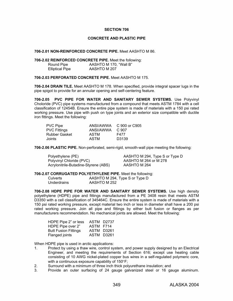
349 ALASKA 2004
SECTION 706
CONCRETE AND PLASTIC PIPE 706-2.01 NON-REINFORCED CONCRETE PIPE. Meet AASHTO M 86. 706-2.02 REINFORCED CONCRETE PIPE. Meet the following:
Round Pipe AASHTO M 170, “Wall B” Elliptical Pipe AASHTO M 207
706-2.03 PERFORATED CONCRETE PIPE. Meet AASHTO M 175. 706-2.04 DRAIN TILE. Meet AASHTO M 178. When specified, provide integral spacer lugs in the pipe spigot to provide for an annular opening and self-centering feature. 706-2.05 PVC PIPE FOR WATER AND SANITARY SEWER SYSTEMS. Use Polyvinyl Choloride (PVC) pipe systems manufactured from a compound that meets ASTM 1784 with a cell classification of 12454B. Ensure the entire pipe system is made of materials with a 150 psi rated working pressure. Use pipe with push on type joints and an exterior size compatible with ductile iron fittings. Meet the following:
PVC Pipe ANSI/AWWA C 900 or C905 PVC Fittings ANSI/AWWA C 907 Rubber Gasket ASTM F477 Joints ASTM D3139
706-2.06 PLASTIC PIPE. Non-perforated, semi-rigid, smooth-wall pipe meeting the following:
Polyethylene (PE) AASHTO M 294, Type S or Type D Polyvinyl Chloride (PVC) AASHTO M 264 or M 278 Acrylonitrile-Butadine-Styrene (ABS) AASHTO M 264
706-2.07 CORRUGATED POLYETHYLENE PIPE. Meet the following:
Culverts AASHTO M 294, Type S or Type D Underdrains AASHTO M 252
706-2.08 HDPE PIPE FOR WATER AND SANITARY SEWER SYSTEMS. Use high density polyethylene (HDPE) pipe and fittings manufactured from a PE 3408 resin that meets ASTM D3350 with a cell classification of 345464C. Ensure the entire system is made of materials with a 150 psi rated working pressure, except material two inch or less in diameter shall have a 200 psi rated working pressure. Join all pipe and fittings by either butt fusion or flanges as per manufacturers recommendation. No mechanical joints are allowed. Meet the following:
HDPE Pipe 2” or less ASTM D2737 HDPE Pipe over 2” ASTM F714 Butt Fusion Fittings ASTM D3261 Flanged joints ASTM D3261
When HDPE pipe is used in arctic applications: 1. Protect by using a thaw wire, control system, and power supply designed by an Electrical
Engineer, and meeting the requirements of Section 616; except use heating cable consisting of 10 AWG nickel-plated copper bus wires in a self-regulated polymeric core, with a continuous exposure capability of 150°F;
2. Surround with a minimum of three inch thick polyurethane insulation; and 3. Provide an outer surfacing of 24 gauge galvanized steel or 16 gauge aluminum.
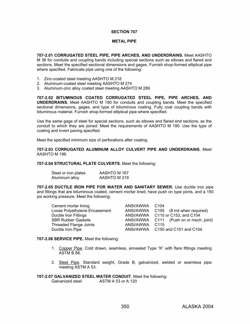
350 ALASKA 2004
SECTION 707
METAL PIPE 707-2.01 CORRUGATED STEEL PIPE, PIPE ARCHES, AND UNDERDRAINS. Meet AASHTO M 36 for conduits and coupling bands including special sections such as elbows and flared end sections. Meet the specified sectional dimensions and gages. Furnish shop-formed elliptical pipe where specified. Fabricate pipe using one of the following: 1. Zinc-coated steel meeting AASHTO M 218 2. Aluminum-coated steel meeting AASHTO M 274 3. Aluminum-zinc alloy coated steel meeting AASHTO M 289 707-2.02 BITUMINOUS COATED CORRUGATED STEEL PIPE, PIPE ARCHES, AND UNDERDRAINS. Meet AASHTO M 190 for conduits and coupling bands. Meet the specified sectional dimensions, gages, and type of bituminous coating. Fully coat coupling bands with bituminous material. Furnish shop-formed elliptical pipe where specified. Use the same gage of steel for special sections, such as elbows and flared end sections, as the conduit to which they are joined. Meet the requirements of AASHTO M 190. Use the type of coating and invert paving specified. Meet the specified minimum size of perforations after coating. 707-2.03 CORRUGATED ALUMINUM ALLOY CULVERT PIPE AND UNDERDRAINS. Meet AASHTO M 196. 707-2.04 STRUCTURAL PLATE CULVERTS. Meet the following:
Steel or iron plates AASHTO M 167 Aluminum alloy AASHTO M 219
707-2.05 DUCTILE IRON PIPE FOR WATER AND SANITARY SEWER. Use ductile iron pipe and fittings that are bituminous coated, cement mortar lined, have push on type joints, and a 150 psi working pressure. Meet the following:
Cement mortar lining ANSI/AWWA C104 Loose Polyethylene Encasement ANSI/AWWA C105 (8 mil when required) Ductile Iron Fittings ANSI/AWWA C110 or C153, and C104 SBR Rubber Gaskets ANSI/AWWA C111 (Push on or mech. joint) Threaded Flange Joints ANSI/AWWA C115 Ductile Iron Pipe ANSI/AWWA C150 and C151 and C104
707-2.06 SERVICE PIPE. Meet the following:
1. Copper Pipe. Cold drawn, seamless, annealed Type “K” with flare fittings meeting ASTM B 88.
2. Steel Pipe. Standard weight, Grade B, galvanized, welded or seamless pipe
meeting ASTM A 53. 707-2.07 GALVANIZED STEEL WATER CONDUIT. Meet the following:
Galvanized steel ASTM A 53 or A 120
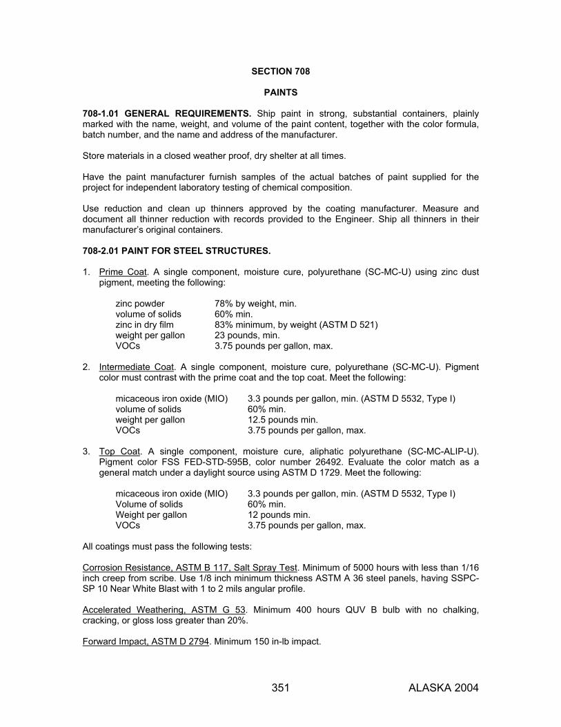
351 ALASKA 2004
SECTION 708
PAINTS 708-1.01 GENERAL REQUIREMENTS. Ship paint in strong, substantial containers, plainly marked with the name, weight, and volume of the paint content, together with the color formula, batch number, and the name and address of the manufacturer. Store materials in a closed weather proof, dry shelter at all times. Have the paint manufacturer furnish samples of the actual batches of paint supplied for the project for independent laboratory testing of chemical composition. Use reduction and clean up thinners approved by the coating manufacturer. Measure and document all thinner reduction with records provided to the Engineer. Ship all thinners in their manufacturer’s original containers. 708-2.01 PAINT FOR STEEL STRUCTURES. 1. Prime Coat. A single component, moisture cure, polyurethane (SC-MC-U) using zinc dust
pigment, meeting the following:
zinc powder 78% by weight, min. volume of solids 60% min. zinc in dry film 83% minimum, by weight (ASTM D 521) weight per gallon 23 pounds, min. VOCs 3.75 pounds per gallon, max.
2. Intermediate Coat. A single component, moisture cure, polyurethane (SC-MC-U). Pigment
color must contrast with the prime coat and the top coat. Meet the following:
micaceous iron oxide (MIO) 3.3 pounds per gallon, min. (ASTM D 5532, Type I) volume of solids 60% min. weight per gallon 12.5 pounds min. VOCs 3.75 pounds per gallon, max.
3. Top Coat. A single component, moisture cure, aliphatic polyurethane (SC-MC-ALIP-U).
Pigment color FSS FED-STD-595B, color number 26492. Evaluate the color match as a general match under a daylight source using ASTM D 1729. Meet the following:
micaceous iron oxide (MIO) 3.3 pounds per gallon, min. (ASTM D 5532, Type I) Volume of solids 60% min. Weight per gallon 12 pounds min. VOCs 3.75 pounds per gallon, max.
All coatings must pass the following tests: Corrosion Resistance, ASTM B 117, Salt Spray Test. Minimum of 5000 hours with less than 1/16 inch creep from scribe. Use 1/8 inch minimum thickness ASTM A 36 steel panels, having SSPC-SP 10 Near White Blast with 1 to 2 mils angular profile. Accelerated Weathering, ASTM G 53. Minimum 400 hours QUV B bulb with no chalking, cracking, or gloss loss greater than 20%. Forward Impact, ASTM D 2794. Minimum 150 in-lb impact.

SECTION 708
352 ALASKA 2004
Abrasion Resistance, ASTM D 4060. Less than 90 mg loss on CS-17 wheel, 1 kg/load, 1000 cycles. Moisture Resistance, ASTM D 4585. Minimum 1000 hours at 100 °F with no change in appearance. Flexibility, ASTM D 522, Cylindrical Mandrel Bend Test. Bend around 1/2 inch diameter mandrel with no cracking. Adhesion, ASTM D 4541. Minimum 500 psi on a certified pull test. Cyclic Weathering, ASTM D 5894. Minimum 5000 hours, 15 cycles with less than 1/16 inch creep from scribe. Use 1/8 inch minimum thickness ASTM A 36 steel panels, having SSPC-SP 10 Near White Blast with 1 to 2 mils angular profile. 708-2.02 PAINT FOR TIMBER. Meet FSS TT-P-19D(1), Paint, Latex (Acrylic Emulsion, Exterior). 708-2.03 PAINT FOR TRAFFIC MARKINGS. Use one of the following: 1. AASHTO M 248, Type F (Alkyd Resin), or 2. FSS TT-P-19D(1) Paint, Latex (Acrylic Emulsion, Exterior), or 3. The current State of Alaska DOT&PF maintenance specification for pavement marking paint. 708-2.04 PAINT FOR CONCRETE. Meet FSS TT-P-19D(1), Paint, Latex (Acrylic Emulsion, Exterior).
SECTION 709
REINFORCING STEEL AND WIRE ROPE 709-2.01 REINFORCING STEEL. Furnish the type, grade, and size specified.
Deformed and Plain Billet-Steel Bars for Concrete Reinforcement AASHTO M 31 Fabricated Deformed Steel Bar Mats for Concrete Reinforcement AASHTO M 54 Steel Welded Wire Fabric, Plain, for Concrete Reinforcement AASHTO M 55 Steel Wire, Plain, for Concrete Reinforcement AASHTO M 32 Epoxy-Coated Reinforcing Bars AASHTO M 284
Use deformed reinforcing bars for concrete structures meeting the tensile properties for the grade specified. Plain bars may be used for spirals and ties. 709-2.02 WIRE ROPE OR WIRE CABLE. Meet AASHTO M 30, for the type specified.

353 ALASKA 2004
SECTION 710
FENCE AND GUARDRAIL
710-2.01 BARBED WIRE. Meet AASHTO M 280, 12.5 gage wire, with 4-point round 14-gage barbs, spaced at 5 inches, Class 1 coating. 710-2.02 WOVEN WIRE. Meet AASHTO M 279, Grade 60, Class 1 coating. 710-2.03 CHAIN LINK FABRIC. Meet AASHTO M 181, Type I (Class D coating), Type II, or Type III, including fittings and hardware. Use 9-gage fabric wire, 2-inch mesh. 710-2.04 METAL BEAM RAIL. Meet AASHTO M 180, Class A, Type II. 710-2.05 FENCE POSTS. Meet AASHTO M 181, Grade 1 or Grade 2, including rails and braces. 710-2.06 GUARDRAIL POSTS AND BLOCKS. Furnish posts and blocks, as specified, meeting the following requirements. 1. Wood Posts and Blocks. Use timber with a stress grade of 1200 psi or more. Testing must
meet the standards of the West Coast Lumber Inspection Bureau. Use timber for posts and blocks that is either rough sawn (unplaned) or S4S with nominal dimensions indicated. Allowable size tolerance of rough sawn blocks in the direction of the bolt holes is ±1/4 inch. Only one combination of post and block finish may be used for any one continuous length of guardrail. Treat all timber to meet Section 714.
2. Steel Posts and Blocks. Meet the section and length specified or shown on the Plans. Use
copper bearing steel when so specified. Use steel meeting the requirements of ASTM A 36 and galvanized per AASHTO M 111.
3. Synthetic Blocks. Products made from alternate materials may be used if accepted by the
FHWA for use on the National Highway System. 710-2.07 GUARDRAIL HARDWARE. Meet AASHTO M 180. Galvanize after fabrication fittings, bolts, washers, and accessories meeting AASHTO M 111 or AASHTO M 232, whichever applies. 710-2.08 WIRE MESH. Galvanized 2-inch mesh (poultry netting), 20 gage wire. 710-2.09 ANCHOR WIRE. Galvanized 9 gage steel wire. 710-2.10 PIPE COUPLINGS. Galvanized nonrecessed, taper tapped, extra heavy couplings. 710-2.11 GUARDRAIL TERMINALS. 1. Slotted Rail Terminal. SRT-350 manufactured by Syro, Inc., Western Division, P.O. Box 99,
Centerville, Utah 84014, Telephone 801-292-4461. Conform to the Syro, Inc. drawings approved by the Department.
2. Extruder Terminal. ET-2000 manufactured by Syro, Inc., Western Division, P.O. Box 99,
Centerville, Utah 84014, Telephone 801-292-4461. Conform to the Syro, Inc. drawings approved by the Department. Use slotted rail for both 25-foot sections for the cable anchor assembly attachment. See Subsection 606-3.05 for installation. Include an object marker, Part No. 3177B, with each ET-2000 installation.
3. Controlled Release Terminal. CRT meeting Standard Drawing G-25.
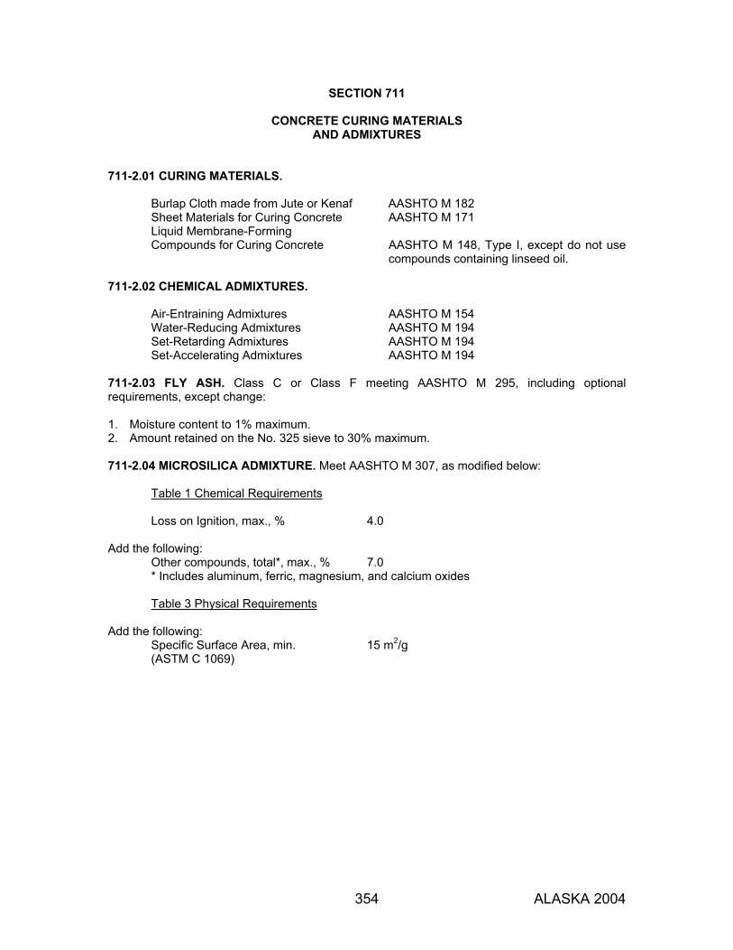
354 ALASKA 2004
SECTION 711
CONCRETE CURING MATERIALS AND ADMIXTURES
711-2.01 CURING MATERIALS.
Burlap Cloth made from Jute or Kenaf AASHTO M 182 Sheet Materials for Curing Concrete AASHTO M 171 Liquid Membrane-Forming Compounds for Curing Concrete AASHTO M 148, Type I, except do not use
compounds containing linseed oil. 711-2.02 CHEMICAL ADMIXTURES.
Air-Entraining Admixtures AASHTO M 154 Water-Reducing Admixtures AASHTO M 194 Set-Retarding Admixtures AASHTO M 194 Set-Accelerating Admixtures AASHTO M 194
711-2.03 FLY ASH. Class C or Class F meeting AASHTO M 295, including optional requirements, except change: 1. Moisture content to 1% maximum. 2. Amount retained on the No. 325 sieve to 30% maximum. 711-2.04 MICROSILICA ADMIXTURE. Meet AASHTO M 307, as modified below:
Table 1 Chemical Requirements Loss on Ignition, max., % 4.0
Add the following: Other compounds, total*, max., % 7.0 * Includes aluminum, ferric, magnesium, and calcium oxides
Table 3 Physical Requirements
Add the following: Specific Surface Area, min. 15 m2/g (ASTM C 1069)

355 ALASKA 2004
SECTION 712
MISCELLANEOUS 712-2.01 WATER. Use water in mixing or curing concrete that is clean and free of oil, salt, acid, alkali, sugar, vegetable or other substances injurious to the finished product. Meet the suggested requirements of AASHTO T 26. Use mix water that contains less than 500 parts per million of chlorides as CI or of sulphates as SO4. Water known to be of potable quality will not require testing. Where the source of water is relatively shallow, enclose the intake to exclude silt, mud, grass, or other foreign materials. Use water for irrigating trees, plants, and seeded areas that is free of elements harmful to plant growth. 712-2.02 CALCIUM CHLORIDE. AASHTO M 144. 712-2.03 LIMESTONE. Use limestone containing not less than 85% of calcium and magnesium carbonates. Meet the standards of the Association of Official Agricultural Chemists. Meet the following gradation for agricultural ground limestone suitable for application by a fertilizer spreader:
Sieve Percent Passing, by Weight, Min. No. 10 100 No. 20 90
No. 100 50 Use soluble or ground limestone in a hydraulic sprayer. Ground limestone must permit complete suspension of insoluble particles in water. 712-2.04 PRECAST CONCRETE CURBING. Portland cement concrete curb units conforming to the lengths, shapes, and other details of the Plans. Use steel reinforcement, where shown on the Plans, meeting Subsection 709-2.01. Furnish a depressed or modified section of curb, when shown on the Plans, for driveways, crossing, closures, or for other reasons. 712-2.05 PRECAST CONCRETE MANHOLE SECTIONS. Meet AASHTO M 199, except that the absorption test will not be required. Reject units with cracks and honeycombed or patched areas in excess of 30 square inches. 712-2.06 FRAMES, GRATES, COVERS, AND LADDER RUNGS. Conform to the plan dimensions and to the following materials requirements.
Gray iron castings AASHTO M 105, Class 35 B. Carbon-steel castings AASHTO M 103. Grade is optional. Structural steel ASTM A 709 Galvanizing AASHTO M 111 Malleable iron castings ASTM A 47. Grade is optional.
712-2.07 CORRUGATED METAL UNITS. Meet AASHTO M 36. When bituminous coating is specified, meet AASHTO M 190, Type A. 712-2.08 GLASS BEADS. Meet AASHTO M 247 Type I, with a moisture resistant coating.

SECTION 712
356 ALASKA 2004
712-2.09 CORPORATION STOPS AND CURB STOPS. Use threaded corporation stops meeting AWWA C800. Use tapped couplings and service saddles as detailed on the Plans and per the manufacturer's recommendations. 712-210 GATE VALVES. All valves must open counter-clockwise, and have ends corresponding to the type of conduit being used. Valves Larger than 3-inch. Iron body, fully bronze mounted, double disc, parallel seat valves, as manufactured to meet AWWA Specifications C500. Valves 3-inch and Smaller. Meet ASTM B 62. Solid bronze, wedge disc, non-rising stem, Class 125, with threaded ends. 712-2.11 VALVE SERVICE BOXES. Furnish the specific style box, stem, and cover shown on the Plans. Inscribe cover with “water” or “W”. Furnish service box of sufficient length to be adjusted an equal amount above and below the final ground surface. Dip boxes in coal tar pitch. Furnish special wrenches, keys, or other tools needed to operate valve and to open valve box lid. Furnish a minimum of one of each type for each style and size of box and lid. Boxes for Valves Larger than 3-inch. Cast iron, not less than 5-1/4 inch shaft, with extension stem adjustable for elevation. Boxes for Valves, 3-inch and Smaller. Cast iron, not less than 4-1/4 inch shaft, with screw type extension stem. 712-2.12 HYDRANTS. Meet AWWA Specifications C-502, “Dry-Barrel Fire Hydrants”. Equip hydrants with 5-inch main valve openings and 6-inch standard mechanical joint hub ends for connection to the auxiliary gate valve. Equip hydrants with an auxiliary gate valve and valve box as shown on the standard details. Use mechanical joints for all connections. Furnish the following types of hose connections, as indicated on the drawings and bid schedule: Single Pumper Hydrants. Two 2-1/2 inch hose connections and one 4-1/2 inch pumper connection. Double Pumper Hydrants. One 2-1/2 inch hose connection and two 4-1/2 inch pumper connections. Furnish hydrants in lengths indicated on the drawings. Furnish hydrants with working parts made of bronze or non-corrodible metal. Paint and coat to meet the cited AWWA Specifications. 712-2.13 GABIONS. Wire Mesh: Use 11 gage minimum wire, except that the selvedge may be heavier. Meet or exceed ASTM A 641 medium hardness and tensile strength; Class 3 coating. Furnish at least one sample of each component of the mesh for testing. Use mesh with 4-inch openings in the longest dimension. Use wire mesh that is designed to be nonraveling. It must resist pulling apart at any of the connections forming the mesh when a single wire strand in a section of mesh is cut. Tie and Connecting Wire: Conform to the same specifications as wire used in the mesh except that it may be not more than 2 gauges smaller. Supply sufficient quantity for securing and fastening all edges of the gabion baskets and diaphragms, for fastening adjacent gabion baskets together, and to provide cross connecting wires in each gabion cell as specified below.

SECTION 712
357 ALASKA 2004
Gabion Baskets. Supply baskets, as specified, in various lengths and heights. Make the lengths multiples (2, 3, or more) of the horizontal width. Furnish all gabion baskets in uniform width of not less than 24 inches or more than 48 inches. Fabricate the sides, ends, lid, and diaphragms for field assembly into a rectangular basket of the required size. Construct gabions as a unit. The base, ends and sides are either to be woven into a single unit or one edge of these members connected to the base so that strength and flexibility at the point of connection is at least equal to that of the mesh. Diaphragms. Where the length of the gabion exceeds its horizontal width, divide the gabion equally with diaphragms of the same mesh and gage as the gabion basket and make compartments of a length approximately equal to horizontal width. Furnish the gabion with the necessary diaphragms secured in proper position on the base section so that no additional tying at this juncture is necessary. Securely selvedge or bind all perimeter edges so that the joints formed by tying the selvedges have approximately the same strength as the body of the mesh. 712-2.14 PREFORMED PAVEMENT MARKING TAPE. 1. General Requirements:
a. Reflectorized plastic pavement markings and legends. Furnish a pliant polymer or homogenous preformed ribbon, 60 mils thick and of specified width, containing glass spheres uniformly distributed throughout the entire cross section. Furnish type that is designed to be inlayed on hot asphalt pavement or attached to existing bituminous pavement with a precoated pressure adhesive or liquid contact cement as herein specified.
b. Use legends and symbols meeting the applicable shapes and sizes in the Alaska Traffic
Manual and the Plans. c. Ensure that the plastic marker will mold itself to pavement contours, breaks, faults, etc. at
normal pavement temperatures and fuse with itself and with previously applied markings of the same composition under normal conditions of use.
2. Composition Requirements: Furnish marker with the following materials uniformly distributed
throughout its cross-sectional area, and with a reflective layer of beads bonded to the top surface:
Material (Composition by Weight, min.) Resins & Plasticizers 20% Pigments 30% Graded Glass Beads 25%
3. Physical Requirements:
a. Tensile Strength. Minimum tensile strength of 100 psi when tested according to ASTM D 638.
b. Plastic Pull Test. A test specimen made by cutting two 1-inch by 3-inch pieces of the
plastic and attaching a 1-inch by 1-inch area at the end of each piece to the other, must support a dead weight of 4 pounds for not less than 5 minutes at a temperature between 70 °F and 80 °F.

SECTION 712
358 ALASKA 2004
c. Pigmentation. Select and blend the pigments to provide a marking film which includes titanium dioxide for white markers and medium chrome yellow for yellow markers meeting standard highway colors through the expected life of the film.
d. Glass Beads. Colorless glass with a minimum index of refraction of 1.50 when tested
using the liquid oil immersion method. Use beads of size and quality to meet the performance requirements for the plastic.
e. Skid Resistance. Meet a minimum skid resistance value of 40 BPN for the surface of the
plastic using ASTM E 303. f. Reflectance. Meet the following initial minimum reflectance values for white and yellow
films at 0.2° and 0.5° observation angles and 86.0° entrance angle using FSS FED-STD-370. Use a test distance of 50 feet and a 2-foot x 2.5-foot rectangular sample. Express specific luminance (SL) as millicandelas per ft2 per foot candle.
Use an angular aperture of both the photoreceptor and light projector of 6 minutes of arc. Use the geometric center of the sample as the reference center and the reference axis perpendicular to the test sample.
White Yellow
Observation Angle 0.2° 0.5° 0.2° 0.5° Specific Luminance 550 380 410 250
g. Reflectivity Retention Tests. Meet the following test requirements:
(1) Taber Abraser Simulation Test. Using a taber abraser with an H-18 wheel and a 125-gram load, inspect the sample at 50, 100 and 200 cycles, under a microscope, to observe the extent and type of bead failure.
No more than 10% of the beads may be lost due to popout and the predominant mode of failure must be “wear down” of the beads.
(2) Qualitative Test. Judge bead bond strengths under a microscope with a magnification
of 5X. The beads when removed must show a portion of the polymer bead bond retained with the beads.
h. Certification. In lieu of running the tests required by this Subsection, provide a
certification from the manufacturer stating the product conforms to these requirements. i. Effective Performance Life. Provide a neat, durable marking that will not flow or distort
due to temperature if the pavement surface remains stable.
The plastic must be weather resistant and through normal traffic wear, show no appreciable fading, lifting or shrinkage and show no significant tearing, roll back, or other signs of poor adhesion.
4. Application. Use a vendor-furnished mechanical applicator for the installation of a 4-inch wide
pressure sensitive adhesive coated material. Provide the mechanical applicator on location for the duration of the installation period. Ensure that a manufacturer's representative is present during the time of the installation to provide technical assistance.
712-2.15 RAISED AND RECESSED PAVEMENT MARKERS. Use reflectors for both raised and recessed pavement markers consisting of an acrylic plastic shell filled with tightly adherent potting compound. Use shells containing one or two glass-covered prismatic reflective faces as called for on the Plans to reflect incidental light from a single or opposite directions.

SECTION 712
359 ALASKA 2004
1. Shell. Molded Methyl Methacrylate meeting ASTM D 788, Gr. 8. 2. Overall Dimensions. 4 x 2 x 3/8 inches. 3. Reflective Surface. Each reflective surface must have a minimum area of 3-1/4 in2 and be
located on a 30-degree angle from a horizontal plane. 4. Optical Requirements. Meet the following minimum optical requirements of the reflective
faces for an observation angle of 0.2 degrees, with the incident light parallel to the base of the reflector:
Horizontal Entrance Angle
Specific Intensity*
White Yellow Red 0 degrees 3 1.8 0.75 20 degrees 1.2 0.72 0.30
*Candelas per footcandle of illumination at the reflector on a plane perpendicular to the incident light.
5. Adhesive. Install pavement markers with an epoxy adhesive recommended by the marker
manufacturer and approved by the Engineer. 6. Color. Match the color of the raised pavement markers to the color of the marking for which
they supplement, substitute, or serve as a positioning guide. 7. Filler. Use a potting compound filler selected for strength, resilience, and adhesion. Bond thin, smooth, untempered glass to the prismatic reflective faces to provide an extremely hard and durable abrasion resistant surface. 712-2.16 TEMPORARY RAISED PAVEMENT MARKERS FOR SHORT-TERM OPERATIONS, SEAL COATS, AND SURFACE TREATMENTS. 1. Marker. L-shaped polyurethane body with retroreflective tape on the top vertical section, with
a self-adhesive base. Reflectorize both faces of the yellow marker and one face of the white marker. Make the marker body of 60 mil minimum thickness polyurethane meeting Table 712-1 with vertical leg approximately 2 inches high by 4 inches wide and base approximately 1-1/4 inch wide.
TABLE 712-1
PROPERTY RESULT ASTM TEST METHOD
Specific Gravity (min.) 1.19 D 792 Hardness 80A D 2240
Tensile Strength (psi, min.) 4600 D 412 Ultimate Elongation (%, min.) 330 D 412 Modulus @ 300% (psi, min.) 1000 D 412
Stiffness @ -20 °F (psi, min.) @ 72 °F (psi, min.)
1700 900
D 1053 D 1053
Compression Set 22 hrs @ 160 °F max. %
65
D 395
Taber Abrasion CS17 wheel

SECTION 712
360 ALASKA 2004
wt loss mg/1000 cycles 3 ---- 2. Reflective Tape. Metalized polycarbonate microprism retroreflective material with acrylic
backing or equal, a minimum 1/4-inch wide by 4 inches long. Provide the minimum optical performance shown in Table 712-2, for an observation angle of 0.2 degrees.
TABLE 712-2
Horizontal Specific Intensity *
Entrance Angle White Yellow 0 degrees 3.5 3.0 30 degrees 2.7 1.7
*Candelas per footcandle of illumination at the reflector on a plane perpendicular to the incident light.
3. Protective Cover. Where chip seals, slurry seals or tack coats are to be utilized after
placement of the temporary raised pavement markers, furnish markers with a protective cover made of clear flexible polyvinyl chloride.
4. Adhesive. Pressure-sensitive material, a minimum of 1/8 inch thick and 3/4 inch wide, factory-
applied to the marker base with release paper.
712-2.17 METHYL METHACRYLATE PAVEMENT MARKINGS. 1. Quality Requirements: Use a marking material formulated for spray application without
reflective beads or anti-skid aggregate. Use glass beads and aggregate designed to be applied to freshly applied material to meet the specified retroreflectance and anti-skid properties.
Use a marking material manufactured from new materials and free from dirt and other foreign material. Use a methyl methacrylate-based resin system for Part "A". Use benzoyl peroxide liquid plasticizer for Part "B".
Submit a manufacturer certification for both the methyl methacrylate material and glass beads to ensure that the materials furnished conform to these Specifications.
2. Performance Properties:
a. No Track Time: Material must be track free after 15 minutes when applied at 40 mils (ASTM D 711).
b. Hardness: Shore Durometer, A-1, 80 minimum after 24 hours. c. Tensile Strength: At break, minimum 125 psi (ASTM D 638). d. Percent Elongation: Minimum 20% (ASTM D 638). e. Water Absorption: Maximum 0.5% (ASTM D 570). f. Chemical Resistance: The material must show no effect after 7-day immersion in anti-
freeze, motor oil, diesel fuel, gasoline, calcium chloride, sodium chloride or transmission fluid.
g. Ultra-violet Light: Ultra-violet light must have no effect. h. Skid Resistance: Minimum 45 units, British pendulum (ASTM E 303). i. Reflectivity: 200 millicandelas, minimum initial j. Viscosity: Spray Material: 5 - 12 Pa•s (ASTM D 2196 Method B, LV Model, Spindle #4 at
60 RPM).

SECTION 712
361 ALASKA 2004
3. Composition: The composition is at the discretion of the manufacturer, but must be essentially comprised of resins, reactive monomers, pigments, plasticizer, benzoyl peroxide, aggregate and glass beads. When mixed in the stated ratio, the material must cure to 99% minimum by weight and volume solids.
712-2.18 GLASS BEADS FOR METHYL METHACRYLATE PAVEMENT MARKINGS. Meet the following requirements:
Beadgun Position►
Front ▼
Rear ▼
Glass Type►
1.5 RI*, Sinker
1.5 RI*, Floater Coating►
Adhesion (ACO2)
Fluorocarbon
Sieve Size ▼
Percent Passing
by Weight ▼
Percent Passing
by Weight ▼
No. 16
100
100 No. 20
90-100
100
No. 30
75-95 No. 40
10-35
No. 50
0-10
15-35 No. 80
0-5
No. 100
0-5 Drop Rate, lb/ft3► 65 40
* Refractive Index

362 ALASKA 2004
SECTION 713
STRUCTURAL TIMBER, LUMBER, AND PILING 713-2.01 Meet AASHTO M 168. Use the grade and species shown on the Plans, or if not shown on the plans use Douglas Fir No. 1 or equal for timber, lumber and piling.
SECTION 714
PRESERVATIVES FOR TIMBER 714-2.01 Apply preservative to all timber that is exposed to weather, water, or soil. Meet the following: 1. Timber. Use the preservatives and treatment processes of AASHTO M133 and Best
Management Practices for the Use of Treated Wood in Aquatic Environments (BMPs), published by the Western Wood Preservers Institute, 601 Main Street, Suite 405, Vancouver, WA 98660 (Phone: 800-279-9663). Use Copper Naphthenate with a retention of preservative conforming to AWPA Use Category 4B for highways and bridges, and Use Category 4A for non-highway. Pressure treat by empty cell method in accordance with AWPA Standards C1 and C2.
2. Glued-Laminated Timber. Use Copper Naphthenate with a retention of preservative
conforming to AWPA Use Category 4B for highways and bridges. Pressure treat by empty-cell process after gluing, in accordance with AWPA Standards C1 and C28.
3. Timber Piling. Use 17 pcf creosote treatment for ground contact or 20 pcf creosote treatment
for marine use, treated in accordance with AWPA Standards C1 and C3. When oil-borne preservatives are used, treat all lumber and timber, including glued-laminated members, by the empty-cell process, except treat material subject to salt water immersion by the full-cell process.

363 ALASKA 2004
SECTION 715
STEEL FOR PILES
715-2.01 SCOPE. Steel used for Structural Steel Piling, Sheet Piling, and Steel Shells for Cast-in-Place Concrete Piles. 715-2.02 GENERAL REQUIREMENTS. Conform to the dimensions, weights, grades, and cross-sections shown on the Plans. Meet the applicable impact test requirements of Subsection 716-2.02 for Zone 3 fracture critical impact testing. 1. Structural Steel for Piling.
a. Meet ASTM A 709, Grade 50T3. Piles 14 inches in diameter or less must be seamless. Fabricate according to the American Petroleum Institute (API) Specification 2B.
b. Meet American Petroleum Institute Specification 5L. c. Meet ASTM A 53 grade B. Piles 14 inches in diameter or less must be seamless.
2. Steel Shells for Cast-in-Place Concrete Piles. Use steel shells of sufficient strength and
rigidity to permit their driving and to prevent distortion caused by soil pressures or the driving of adjacent piles, until filled with concrete. Ensure pipe is sufficiently tight to exclude water during the placing of the concrete.
3. Sheet Piling. Meet the requirements of AASHTO M 202 for sheet piles to be a permanent part
of the structure. Maintain the integrity of the interlock when the piles are in place. 715-2.03 CERTIFICATION. Furnish 4 copies of a certified mill test report covering chemical and physical tests conducted on the steel to the Department for each heat number of metal included in the shipment.

364 ALASKA 2004
SECTION 716
STRUCTURAL STEEL 716-2.01 SCOPE. Structural steel for highway bridges and other structural purposes. 716-2.02 GENERAL REQUIREMENTS. Meet the following: 1. General requirements for delivery of rolled steel plates, shapes, sheet piling, and bars for structural use ASTM A 6 2. Structural Steel ASTM A 709 3. High Strength Low-Alloy Columbium Vanadium Steels of Structural Quality ASTM A 709 4. High Strength Low-Alloy Steel with 50,000 psi minimum yield point to 4 inches thick ASTM A 709 5. High Yield Strength, Quenched and Tempered Alloy Steel Plate Suitable for Welding ASTM A 709 6. Welded and Seamless, High Strength, Low-Alloy Tubing ASTM A 618 7. Filler Metal for Applicable Arc-Welding Electrodes AWS Specifications 8. Stud Shear Connectors ASTM A 108 Gr. 1015, or 1020 9. Raised Pattern Plate. Where shown on the Plans, use plates for steel expansion joints
fabricated from steel plate, with a raised pattern surface meeting the following requirements:
a. Use diagonal type pattern, with the intersecting diagonals at right angles to one another. Use the same material for the raised portions of the pattern as the base metal of the plate. The raised pattern must be an inherent part of the plate. The pattern must be continuous throughout the surface of the plate and the projections along any diagonal must be spaced alternately with the projections along the normal diagonals.
b. Use plate with projections that are self-draining and self-cleaning and provide a skid-
resistant surface from all angles of approach. The projections must have flat tops and be designed not to chip, crack, split, or buckle at their intersection with the base metal.
10. Impact Test Requirements.
a. Meet the supplemental requirements for impact toughness testing (Charpy V-Notch) and marking under ASTM A 709, Zone 3. These supplemental requirements are mandatory for material designated on the Plans as fracture critical (F) or as main members subject to tensile stress (T).
b. Submit impact test reports to the Engineer. 716-2.03 HIGH TENSILE STRENGTH BOLTS. Meet the following:
High Strength Bolts for Structural Steel Joints AASHTO M 164 Nuts for AASHTO M 164 bolts AASHTO M 292 Hardened Steel Washers AASHTO M 293

SECTION 716
365 ALASKA 2004
716-2.04 STEEL GRID FLOORS. Meet ASTM A 709, Grade 36. Unless the material is galvanized, it must have a copper content of 0.2% minimum. Unless painting of floors is specified in the Special Provisions, open type floors must be galvanized. 716-2.05 MACHINE BOLTS. Meet ASTM A 307. 716-2.06 STEEL PIPE. Meet ASTM A 53. 716-2.07 GALVANIZING. Hot-dip galvanize structural steel shapes, plates, bars and their products according to AASHTO M 111. Galvanize tubes and piles on inside and outside surfaces. Hot-dip galvanize steel poles, mast arms, pedestals, and posts, according to AASHTO M 111. Submerge each component in the galvanizing kettle in one dip. Use only the dry kettle method of fluxing for high tower poles. Hot-dip galvanize all anchor bolts, nuts, washers, tie-rods, clamps, and other miscellaneous ferrous parts in conformance with AASHTO M 232. After galvanizing, ensure that the bolt threads accept galvanized standard nuts without requiring tools or causing removal of protective coatings. Galvanize rigid metal conduit in conformance with AASHTO M 232. For Steel Bridge members, apply 10 mils zinc galvanizing by spray-metalizing process according to Steel Structures Painting Council (SSPC) Coating System Guide No. 23.00. Prepare surfaces before galvanizing in accordance with SSPC-SP 5 White Metal Blast Cleaning. 716-2.08 CERTIFICATION. Submit 5 copies of a certified mill test report covering chemical and physical tests conducted on all structural steel to the Department for the material in each shipment.

366 ALASKA 2004
SECTION 718
STEEL FORGINGS 718-2.01 SCOPE. Steel forgings from which pins, rollers, trunnions or other forged parts are to be fabricated. 718-2.02 GENERAL REQUIREMENTS. Meet the dimensions shown on the Plans and the following specifications. 1. Alloy Steel Forgings (general industrial use): AASHTO M 102, Class G. 2. Carbon Steel Forgings (general industrial use): AASHTO M 102, Class C. 3. Pins and Rollers
a. More than 7 inches in Diameter: Annealed carbon-steel forgings meeting AASHTO M 102, Class C.
b. 7 inches or Less in Diameter: Either annealed carbon-steel forgings meeting
AASHTO M 102, Class C or cold finished carbon-steel shafting meeting AASHTO M 169, Grade 1016 to 1030, inclusive, with a minimum Rockwell Scale B hardness of 80. Material not meeting the specifications for hardness may be accepted provided it develops a minimum tensile strength of 66,000 psi and a minimum yield point of 33,000 psi.
4. Threads for Pins: ANSI B 1.1, Class 2A coarse thread series. Thread pin ends, having a
diameter of 1-3/8 inch or more, 6 threads to the inch. 718-2.03 CERTIFICATION. Submit 5 copies of a certified mill test report covering chemical and physical tests for the material in each shipment.
SECTION 719
STEEL, GRAY-IRON AND MALLEABLE-IRON CASTINGS
719-2.01 SCOPE. Steel, gray-iron and malleable-iron castings intended for various uses as shown on the Plans. 719-2.02 GENERAL REQUIREMENTS. Meet the size and dimensions shown on the Plans, be true to pattern in form, and conform to the following specifications.
Carbon Steel Castings AASHTO M 103, Grade 65-35 Chromium Alloy Steel Castings AASHTO M 163, Grade CA-15 Gray-Iron Castings AASHTO M 105, Class 30B Malleable-Iron Castings ASTM A 47, Grade 24018

367 ALASKA 2004
SECTION 720
ELASTOMERIC PADS
720-2.01 Meet AASHTO M 251, with the following revisions: 4.1 Properties of the Elastomer. Replace the first sentence with the following: Use elastomeric compound in the construction of the bearings containing only virgin natural polyisoprene (natural rubber) as the raw polymer. Do not use neoprene. Properties and requirements elsewhere in AASHTO M 251 pertaining solely to polychloroprene (neoprene) do not apply. Use elastomer compound classified as low temperature Grade 5 and meeting the requirements of the Shear Modulus Test, paragraph 9.4. Amend Table 1 as follows: Replace “25” with “50” in the row labeled “Ozone Resistance, Concentration of ozone during test”. Replace “48” with “100” in the row labeled “Ozone resistance, Duration of test”. Add the following paragraph: 5.5. Fabricate pads over 3/4 inch thick with alternating laminations of elastomer and metal or fabric reinforcements. The outside laminations must be metal or fabric with a minimum elastomer cover as shown on the Plans. Use elastomer laminations 1/2 inch thick ±1/8 inch.

368 ALASKA 2004
SECTION 721
PRESTRESSING STEEL AND FITTINGS 721-2.01 SCOPE. Prestressing steel and fittings used in pre-tensioned and post-tensioned concrete construction. 721-2.02 PRESTRESSING STEEL. Meet the following:
Strand AASHTO M 203 Wire AASHTO M 204. Do not use oil-tempered wires. High Strength Alloy Steel Bars AASHTO M 275
721-2.03 ANCHORAGES. Use an anchorage system in post-tensioned concrete construction designed to limit the bearing stresses created by the anchorage to the following values: 1. At working load: fcp= 0.6 f 'c Ab'/Ab but not greater than f 'c
2. At transfer load: fcp= 0.8 f 'c i (Ab'/Ab) - 0.2 but not greater than 1.25 f 'c i where fcp= permissible compressive concrete stress
f 'c= compressive strength of concrete
f 'c i = compressive strength of concrete at time of initial prestress
Ab' = maximum area of the portion of the concrete anchorage surface that is geometrically similar to and concentric with the area of the anchorage
Ab = bearing area of the anchorage
3. As used in the above equations, fcp is the average bearing stress (P/A) in the concrete
computed by dividing the force P of the prestressing steel by the net projected area Ab between the concrete and the bearing plate or other structural element of the anchorage which has the function of transferring the force to the concrete.
The anchorages must develop at least 90% of the specified minimum ultimate strength of the prestressing steel. Localized yielding of anchor components is permitted; however, generalized permanent yielding or deformation is not permitted. 721-2.04 COUPLINGS. Use coupling of tendons only when approved. All couplings must develop at least 95% of the specified minimum ultimate strength of the prestressing steel without permanent deformation. Localized yielding of coupling components is permitted; however, generalized permanent yielding is not permitted. The coupling of tendons must not reduce the elongation at rupture below the requirements of the tendon itself. Enclose couplings and/or coupling components in housings large enough to permit the necessary movements. Provide fittings to allow complete grouting of all the coupling components. 721-2.05 CONFORMANCE TESTING. Have the post-tensioning system supplier submit data from conformance tests to confirm the adequacy of the system. Minimum requirements for the conformance tests are listed in the following paragraph. Use a test assembly consisting of standard production quality components with tendons at least 10 feet long. Test the assembly to accurately determine the yield strength, ultimate strength, and percent elongation of the complete system, to insure compliance with this specification.

369 ALASKA 2004
SECTION 722
BRIDGE RAILING 722-2.01 BRIDGE RAILING.
Steel tube rail elements ASTM A 500, Grade B Steel Thrie Beam elements AASHTO M 180, Class B, Type II Posts ASTM A 709, Grade 36 Machine bolts, cap screws, nuts and washers ASTM A 307 High strength bolts, nuts and washers AASHTO M 164 and Subsection 716-2.03 Anchor studs AASHTO M 169, Gr. 1015, or 1020 Shims, plates and sleeves ASTM A 709, Grade 36 Galvanize steel portions of railing Meet AASHTO M 111 or M 232, after fabrication. whichever is applicable.
SECTION 723
WATER STOPS 723-2.01 WATER STOPS. 1. Rubber water stops, either molded or extruded from plain rubber or synthetic rubber. Meet
the requirements of ASTM D 2000. 2. Use water stops formed with an integral cross section. No splices are permitted in straight
strips. Strips and special connection pieces must be free from all porosity. All junctions in the special connection pieces must be full molded. During the vulcanizing period securely hold the joints with suitable clamps. The material at the splices must be dense and homogeneous throughout the cross section.
3. Full mold all field splices and bevel splice faces at an angle of 45 degrees or flatter. All
finished splices must have a tensile strength of not less than 50% of the unspliced material. 4. Obtain the Engineer’s approval to use water stops of materials other than those specified.
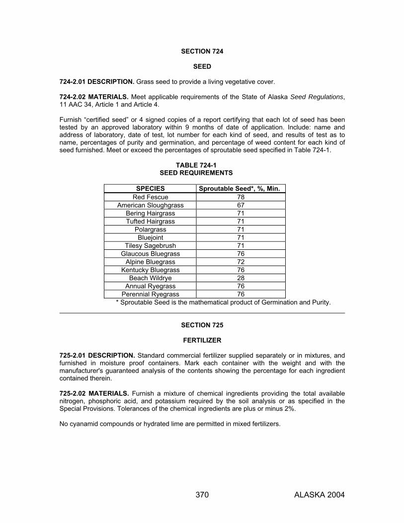
370 ALASKA 2004
SECTION 724
SEED 724-2.01 DESCRIPTION. Grass seed to provide a living vegetative cover. 724-2.02 MATERIALS. Meet applicable requirements of the State of Alaska Seed Regulations, 11 AAC 34, Article 1 and Article 4. Furnish “certified seed” or 4 signed copies of a report certifying that each lot of seed has been tested by an approved laboratory within 9 months of date of application. Include: name and address of laboratory, date of test, lot number for each kind of seed, and results of test as to name, percentages of purity and germination, and percentage of weed content for each kind of seed furnished. Meet or exceed the percentages of sproutable seed specified in Table 724-1.
TABLE 724-1 SEED REQUIREMENTS
SPECIES Sproutable Seed*, %, Min.
Red Fescue 78 American Sloughgrass 67
Bering Hairgrass 71 Tufted Hairgrass 71
Polargrass 71 Bluejoint 71
Tilesy Sagebrush 71 Glaucous Bluegrass 76
Alpine Bluegrass 72 Kentucky Bluegrass 76
Beach Wildrye 28 Annual Ryegrass 76
Perennial Ryegrass 76 * Sproutable Seed is the mathematical product of Germination and Purity.
SECTION 725
FERTILIZER
725-2.01 DESCRIPTION. Standard commercial fertilizer supplied separately or in mixtures, and furnished in moisture proof containers. Mark each container with the weight and with the manufacturer's guaranteed analysis of the contents showing the percentage for each ingredient contained therein. 725-2.02 MATERIALS. Furnish a mixture of chemical ingredients providing the total available nitrogen, phosphoric acid, and potassium required by the soil analysis or as specified in the Special Provisions. Tolerances of the chemical ingredients are plus or minus 2%. No cyanamid compounds or hydrated lime are permitted in mixed fertilizers.

371 ALASKA 2004
SECTION 726
TOPSOIL
726-2.01 TOPSOIL. Furnish a natural friable surface soil without admixtures of undesirable subsoil, refuse, or foreign materials. Meet the following: 1. Reasonably free from roots, clods, hard clay, noxious weeds, tall grass, brush, sticks, stubble
or other litter, and be free-draining and non-toxic. 2. Contain between 3% and 20% organic matter as determined by loss-on-ignition of oven dried
samples according to ATM 203. 3. Grading requirements:
Sieve Percent Passing 2 in. 100 No. 4 75-100 No. 10 60-100
No. 200 10-70 Notify the Engineer of the source of topsoil at least 30 days prior to delivery of topsoil to the project from that location. The Engineer will inspect and test the topsoil and its source before approval will be granted for its use. Unsuitable topsoil sources may be used if, prior to delivery to the project, sufficient organic matter in the form of pulverized peat moss or rich organic soil from other sources is thoroughly mixed with the topsoil to provide a product meeting the above requirements. Use the application rates, determined by the Engineer, of fertilizer and limestone per acre of ground area of topsoil, based on soil analysis tests so that the total natural and applied chemical constituents are as follows:
Nitrogen 45 - 65 pounds per acre Phosphoric Acid 45 - 90 pounds per acre Potassium 45 - 90 pounds per acre
TABLE 726-1
LIMESTONE REQUIREMENTS
Soil pH Limestone, tons/acre Above 6.0 0
5.0-6.0 1.5 Below 5.0 3.0
372 ALASKA 2004
SECTION 727
SOIL STABILIZATION MATERIAL 727-2.01 MULCH. Use one of the following: 1. Wood Cellulose Fiber or Natural Wood Fiber. Processed wood fiber with the following
characteristics:
a. Contains no germination- or growth-inhibiting factors. b. Will remain in uniform suspension in water under agitation and will blend with grass seed,
fertilizer and other additives to form a homogeneous slurry. c. Will form a blotter-like ground cover on application, having moisture absorption and
percolation properties and the ability to cover and hold grass seed in contact with soil. d. Dyed a suitable color to facilitate inspection of its placement.
Ship the mulch material in packages of uniform weight (plus or minus 5%) and bearing the name of the manufacturer and the air-dry weight content. Use a commercial tackifier on all slopes steeper than 2:1. Use the amount recommended by the manufacturer.
2. Dried Peat Moss. Partially decomposed fibrous or cellular stems and leaves of any of several
species of Sphagnum mosses with the following characteristics:
a. Chopped or shredded to allow distribution through normal hydraulic type seeding equipment and capable of being suspended in water to form part of a homogeneous slurry.
b. Free from woody substances and mineral matter such as sulfur or iron and with a pH
value of between 4.0 and 6.5. c. Furnished in an air dry condition and contain less than 35% moisture by weight. Have a
water holding capacity of not less than 800% by weight on an oven dry basis. d. Non-toxic.
727-2.02 MATTING. Use one of the following: 1. Burlap. Standard weave with a weight of 3.5 to 10 oz/ yd2. 2. Jute Mesh Fabric. Cloth of a uniform, open, plain weave of undyed and unbleached single
jute yarn. Use yarn that is loosely twisted and not varying in thickness more than one-half its normal diameter. Furnish jute mesh in rolled strips meeting the following requirements:
a. Width: 45 to 48 inches, ± 1 inch b. 78 warp-ends per width of cloth (minimum) c. 41 weft-ends per yard (minimum) d. Weight: 20 ounces per linear yard, ± 5%
SECTION 727
373 ALASKA 2004
3. Woven Paper or Sisal Mesh Netting. Woven from twisted yarns available in rolls 45 to 48 inches wide. Mesh may vary from closed to open weave, ranging from 1/8 to 1/4 inch openings. Shrinkage after wetting may not exceed 20% of the surface area.
4. Knitted Straw Mat. Commercially manufactured erosion control blanket. Use photodegradable
netting and biodegradable thread. Use straw from oats, wheat, rye, or other approved grain crops that are free from noxious weeds, mold, or other objectionable material. May contain coconut or fiber to reinforce the straw. Follow the manufacturer's published recommendations.
5. Woven/Curled Wood Blanket. Machine produced mat of curled wood shavings with a
minimum of 80% 6-inch or longer fibers, with consistent thickness and the fibers evenly distributed over the entire area of the blanket. Smolder resistant without the use of chemical additives. Cover the top side of the blanket with biodegradable extruded plastic mesh.
727-2.03 STAPLES. U-shaped staples for anchoring matting, approximately 6 inches long and 1 inch wide. Machine-made: No. 11 gage or heavier steel wire. Hand-made: 12-inch lengths of No. 9 gage or heavier steel wire.

374 ALASKA 2004
SECTION 729
GEOSYNTHETICS 729-2.01 GEOTEXTILE, SEPARATION AND STABILIZATION. 1. Separation. Meet AASHTO M 288 for Separation, except provide a minimum permittivity of
0.05 sec-1
2. Stabilization. Meet AASHTO M 288 for Stabilization, except provide a minimum permittivity of
0.08 sec-1
729-2.02 GEOTEXTILE, SUBSURFACE DRAINAGE AND EROSION CONTROL. 1. Subsurface Drainage. Meet AASHTO M 288 for Subsurface Drainage. 2. Erosion Control. Meet AASHTO M 288 for Permanent Erosion Control. 729-2.03 PAVING FABRIC. Meet AASHTO M 288 for Paving Fabric. 729-2.04 SILT FENCE. Meet AASHTO M 288 for Temporary Silt Fence. 729-2.05 GEOGRID. Biaxial polymer grid, specifically fabricated for use as a soil reinforcement, having high tensile strength, modulus, and stiffness in both principal directions. Use a single-layered, integrally-formed grid structure. Use either extruded or punched and drawn polypropylene or high density polyethylene. Geogrid must be UV-stabilized, chemically inert, and meet the physical requirements in Table 729-1. Package, label, handle, and store geogrid material according to ASTM D 4873.
TABLE 729-1 GEOGRID PHYSICAL REQUIREMENTS
PROPERTY REQUIREMENT TEST METHOD Average Aperture Size, MD(1) XD(2)
0.8-2.0 in. 0.8-2.0 in.
I.D Calipered Maximum Inside Dimension
Installation Damage Resistance
80% (3) Sample per D5818 Test per D6637
Rib Thickness, min. (Nominal) 40 mils Rib Thickness Calipered Minimum
Tensile Strength, min. At 2% Strain At 5% Strain
MD & XD 400 lb/ft 800 lb/ft
ASTM D6637
Junction Strength, min. 90%(4) GRI GG-GG2 (1) MD: Machine Direction which is along roll length. (2) XD: Cross machine direction which is across roll width. (3) 80% relative to pre-installation Tensile Strength values. Perform Test install using GP or GW Class soil. (4) 90% relative to Ultimate Tensile Strength as determined by ASTM D6637
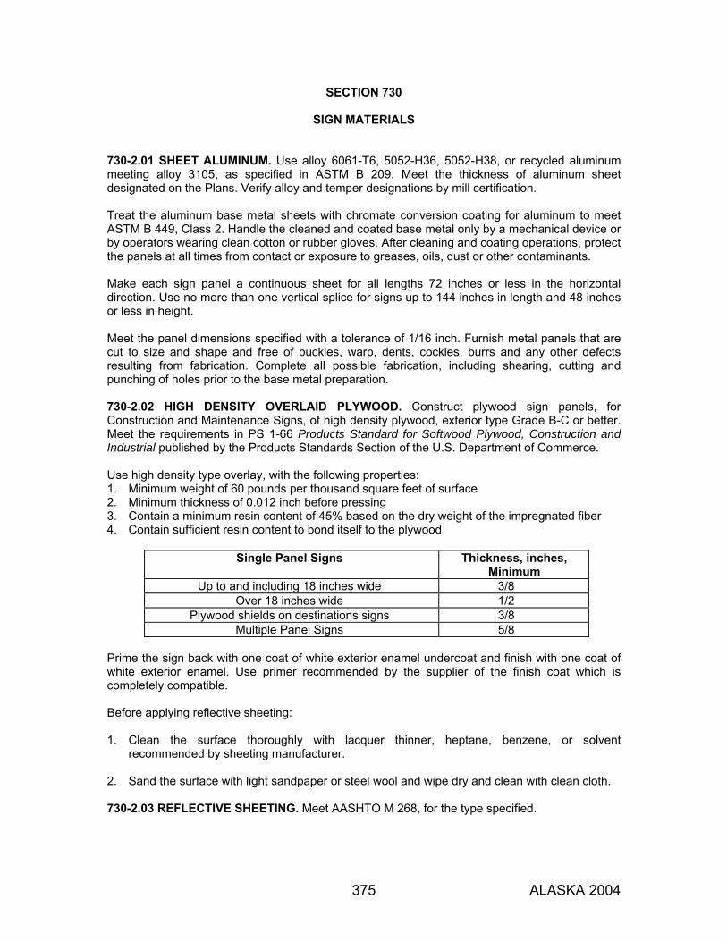
375 ALASKA 2004
SECTION 730
SIGN MATERIALS 730-2.01 SHEET ALUMINUM. Use alloy 6061-T6, 5052-H36, 5052-H38, or recycled aluminum meeting alloy 3105, as specified in ASTM B 209. Meet the thickness of aluminum sheet designated on the Plans. Verify alloy and temper designations by mill certification. Treat the aluminum base metal sheets with chromate conversion coating for aluminum to meet ASTM B 449, Class 2. Handle the cleaned and coated base metal only by a mechanical device or by operators wearing clean cotton or rubber gloves. After cleaning and coating operations, protect the panels at all times from contact or exposure to greases, oils, dust or other contaminants. Make each sign panel a continuous sheet for all lengths 72 inches or less in the horizontal direction. Use no more than one vertical splice for signs up to 144 inches in length and 48 inches or less in height. Meet the panel dimensions specified with a tolerance of 1/16 inch. Furnish metal panels that are cut to size and shape and free of buckles, warp, dents, cockles, burrs and any other defects resulting from fabrication. Complete all possible fabrication, including shearing, cutting and punching of holes prior to the base metal preparation. 730-2.02 HIGH DENSITY OVERLAID PLYWOOD. Construct plywood sign panels, for Construction and Maintenance Signs, of high density plywood, exterior type Grade B-C or better. Meet the requirements in PS 1-66 Products Standard for Softwood Plywood, Construction and Industrial published by the Products Standards Section of the U.S. Department of Commerce. Use high density type overlay, with the following properties: 1. Minimum weight of 60 pounds per thousand square feet of surface 2. Minimum thickness of 0.012 inch before pressing 3. Contain a minimum resin content of 45% based on the dry weight of the impregnated fiber 4. Contain sufficient resin content to bond itself to the plywood
Single Panel Signs Thickness, inches, Minimum
Up to and including 18 inches wide 3/8 Over 18 inches wide 1/2
Plywood shields on destinations signs 3/8 Multiple Panel Signs 5/8
Prime the sign back with one coat of white exterior enamel undercoat and finish with one coat of white exterior enamel. Use primer recommended by the supplier of the finish coat which is completely compatible. Before applying reflective sheeting: 1. Clean the surface thoroughly with lacquer thinner, heptane, benzene, or solvent
recommended by sheeting manufacturer. 2. Sand the surface with light sandpaper or steel wool and wipe dry and clean with clean cloth. 730-2.03 REFLECTIVE SHEETING. Meet AASHTO M 268, for the type specified.
SECTION 730
376 ALASKA 2004
730-2.04 SIGN POSTS. Use the type and size of posts designated on the Plans. 1. Metal Pipe Posts.
a. Fabricate from steel pipe to meet ASTM A 53 Standard Weight (Schedule 40), Type E or S, Grade B. Furnish square posts with 7/16 inch diameter holes drilled or punched as necessary to permit mounting of the sign.
b. Hot dip galvanize to meet AASHTO M 111 after fabrication. When cutting metal posts
after hot dip galvanizing, minimize damage to the zinc coating and protect all exposed surfaces by treating the exposed area.
c. Repair galvanized surfaces that are abraded or damaged at any time after the application
of the zinc coating to meet the applicable provisions of AASHTO M 36. 2. Perforated Steel Posts.
a. Fabricate posts from 0.105-inch (12 gauge) thick cold-rolled carbon steel sheets, commercial quality, to meet ASTM A 653 and ASTM A 924. Zinc coat, both sides, to meet coating designation G90. Form posts into a steel tube, roll to size, and weld in the corner.
b. Perforate all members for their entire length with 7/16 inch diameter holes on 1 inch
centers. c. Furnish members that are straight and with a smooth, uniform finish, with no splices. d. Ensure that all perforations and cut off ends are free from burrs. e. Ensure that consecutive sizes will telescope freely with a minimum of play.
3. Finished Wooden Posts.
a. Meet AASHTO M 168, except limit the sweep (circular deviation from a straight line) to 0.08 foot in 10 feet.
b. Pressure treat wooden posts with one of the following:
(1) Pentachlorophenol in light oil solvent (2) Acid Copper Chromite (3) Ammoniacal Copper Arsenate (4) Chromated Copper Arsenate (5) Chromated Zinc Arsenate (6) Chromated Zinc Chloride (7) Copperized Chromated Zinc Chloride
Use the methods specified in Section 714, except do not incise lumber posts for signs. Meet the minimum retention of preservative specified for “Posts.”
c. Treat all field cuts and holes in wooden posts by thoroughly swabbing, spraying or
brushing with two coats of the same type of preservative as initially used. Apply wood preservative when the moisture content of the wood is less than 25% and there is no free moisture on the surface. Protect posts treated during wet weather from moisture. Apply wood preservative with suitable brush or other means that will result in adequate penetration.

SECTION 730
377 ALASKA 2004
4. Wide Flange Posts.
a. Steel. Meet ASTM A 36. b. Hot dip galvanize to meet AASHTO M 111 after fabrication. When cutting galvanized
metal posts, minimize damage to the zinc coating and treat the exposed area as follows. c. Repair galvanized surfaces that are abraded or damaged at any time after the application
of the zinc coating to meet the applicable provisions of AASHTO M 36. 5. Flanged Channel Posts. Use either of the following:
a. Aluminum meeting ASTM B 221, alloy 6061-T6. b. Steel meeting ASTM A 36. Galvanize steel posts per AASHTO M 111.
6. Square Non-Perforated Steel Tubes.
a. Fabricate from 3/16 inch thick cold-rolled carbon steel sheets, commercial quality, to meet ASTM A 500, Grade B. Form posts into a steel tube, roll to size, and weld in the corner. Furnish with 7/16-inch diameter holes drilled or punched as necessary to permit mounting of the sign.
b. Hot dip galvanize to meet AASHTO M 111 after fabrication. When cutting metal posts
after hot dip galvanizing, minimize damage to the zinc coating and protect all exposed surfaces by treating the exposed area.
c. Repair galvanized surfaces that are abraded or damaged at any time after the application
of the zinc coating to meet the applicable provisions of AASHTO M 36. 730-2.05 FLEXIBLE DELINEATOR POSTS. Durable plastic material meeting the dimensions and colors shown on the Plans. Resistant to ultraviolet light, ozone and hydrocarbon damage and remain flexible at a temperature of minus 40 °F. Provide posts with reflectors that are capable of self-erecting and remaining serviceable after 5 head-on impacts at 55 mph and 10 impacts at 35 mph with an automobile at an air temperature of plus 40 °F. 730-2.06 ACRYLIC PRISMATIC REFLECTORS. Meet AASHTO M 290 and the dimensions and colors shown on the Plans.

378 ALASKA 2004
SECTION 740
SIGNALS AND LIGHTING MATERIALS
740-2.01 GENERAL. Use electrical materials, devices, fittings, and hardware that conform to applicable NEMA and ANSI standards. Use electrical products that are Third Party Labeled or Listed (by an approved independent electrical testing laboratory such as UL, ETL, CSA, etc.), unless otherwise indicated on the Materials Certification List (MCL). Ensure that all material and workmanship, as determined by the Department, conform to the standards of the NEC, the NESC, and local safety codes as adopted and amended by the authority having jurisdiction. 740-2.02 SIGNAL AND LIGHTING STRUCTURES. 1. Design. Design structures for highway lighting and traffic signals to conform to the 1994
Edition of AASHTO Standard Specifications for Structural Supports for Highway Signs, Luminaires and Traffic Signals. Design high tower lighting structures to conform to the 2001 Edition of AASHTO Standard Specifications for Structural Supports for Highway Signs, Luminaires and Traffic Signals.
All plans and calculations must be performed and stamped by a registered professional engineer. Submit the stamped plans and calculations for each pole to the Engineer for approval. Design for all stresses on the completed structure with all hardware in place. Show the design wind loads, projected areas, wind drag coefficients, material properties, and other design information on the plans. Include a summary of the loads used in each pole’s design. Design each electrolier to include a traffic sign, 48 inches by 48 inches, located with its centroid 14 feet above the base of the pole. Determine the shaft lengths and mast arm connector plate locations of all poles to meet the plan mounting heights of luminaires and traffic heads. Design signal mast arms so that no signal heads or signs will be mounted within 12 inches either side of a mast arm extension splice. Design all poles and mast arms with a round or 16-sided cross section, except high tower poles may also be 12-sided cross section.
2. Fabrication. Fabricate all posts, poles, and mast arms from tapered steel tubes. Fabricate tubes with walls up to ½-inch thick from the pre-qualified base metals listed in AWS D1.1 and which feature maximum yield strengths of 70,000-psi. Fabricate all elements greater than ½-inch thick from steel that conforms to ASTM A 709 and meets the Fracture Critical Impact Test requirements for zone 3. Fabricate 10 feet long signal posts from sheet steel that features a minimum thickness of 11 US Standard Gage. Fabricate each post with a minimum inside diameter of five inches at the base plate. Use a three and one-half inch long piece of 4-inch schedule 40 pipe that conforms to ASTM A 53 Grade B as a post-top adapter. Fabricate poles from full length sheets or shorter sections. Fabricate each section from not more than 2 pieces of sheet steel. When using 2 pieces, place the longitudinal welded seams directly opposite one another. Place the welded seams on adjacent sections to form continuous straight seams from the base to the top of the pole. The Department will not accept poles and mast arms made with laminated steel elements.

SECTION 740
379 ALASKA 2004
Hot dip galvanize all pole segments and attachments to meet AASHTO M 111, 4 mil thickness and these specifications. Completely submerge pole segments in one dip in a kettle of concentrated zinc ammonium chloride flux solution heated to 130 oF, then completely submerge in one dip in a separate kettle of prime western grade zinc heated to approximately 825 oF. Galvanize all bolts and fasteners to meet AASHTO M 232.
Poles must be straight, with sweep not exceeding 3/4 inch throughout the length of the pole. Do not put holes in the pole segments unless shown on the design drawings and provided for in the engineering calculations. Fabricate pile cap adapters from grade X42 steel line pipe that conforms to API 5L and from steel plate that conforms to ASTM A 709 Grade 50. Attach the anchor plate to the pile section with a complete joint penetration (CJP) weld. Fabricate the anchor plate to match the base plate of the lighting standard.
3. Mill Certification. Submit the mill certification for all steel items (piles, plates, bolts, and all
other related items) to the Engineer for approval. 4. Welding. Perform all welding to conform to Subsection 504-3.01, Item 8. Welding and the
following:
a. Make all welds continuous. Grind all exposed welds flush with the base metal, except fillet welds and seam welds on top of mast arms. Grinding the seam welds on 16- sided poles is not required.
b. Use complete Joint Penetration (CJP) groove welds for all circumferential welds. Only
one-time repair of circumferential welds is allowed without written permission of the Engineer.
c. Use CJP groove welds on longitudinal seams within 6 inches of CJP circumferential
welds. Use partial joint penetration (PJP) longitudinal seam welds in all other seam weld locations. PJP welds must provide at least 60% penetration.
d. Welded support to base plate connections must be either (1) CJP groove welds or (2)
socket-type joints with two fillet welds. When CJP groove welds are used, additional fillet welds may be used when deemed necessary by the designer.
e. Inspect 100 percent of CJP welds by either radiography (RT) or ultrasound (UT). Inspect
a random 25 percent of all fillet and PJP welds by magnetic particle (MT). If a defect is found, inspect 100 percent of all fillet and PJP welds made to fill the order. Show NDE symbols on the plans.
5. Miscellaneous. Neatly round all exposed corners of the plates that make up the base
assembly to a 1/8-inch radius and finish smooth all exposed edges. Provide shafts with slip-fitter shaft caps. Orient hand holes to face down-stream of the traffic flow. Furnish anchor bolts and nuts required for relocating existing poles. Identify critical information for all poles and arms with visible permanent aluminum tags that contain the information shown in Table 740-1. The measurements shown are for illustration purposes only. The tags must be 1-1/2 inches by 3 inches for a 1-line message and 1-1/2 x 4 inches for a 2-line message. The letter size must be 1/4 inch high and the spacing between the edge of the tag and text and between text must be 3/8 inch. Secure the tags with two 1/8-inch blind rivets at the base of poles and the underneath side of mast arms. If a signal mast arm extension is required, mark it with a tag with the same message as the signal mast arm.
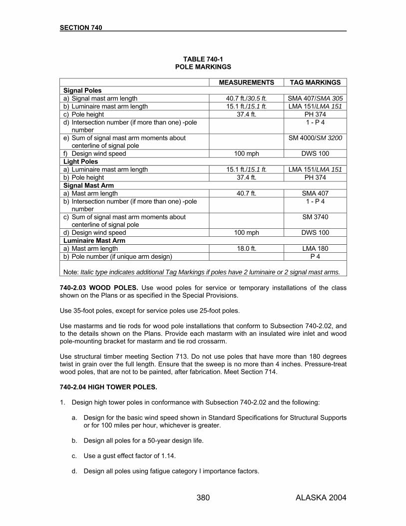
SECTION 740
380 ALASKA 2004
TABLE 740-1
POLE MARKINGS MEASUREMENTS TAG MARKINGS Signal Poles a) Signal mast arm length 40.7 ft./30.5 ft. SMA 407/SMA 305 b) Luminaire mast arm length 15.1 ft./15.1 ft. LMA 151/LMA 151 c) Pole height 37.4 ft. PH 374 d) Intersection number (if more than one) -pole
number 1 - P 4
e) Sum of signal mast arm moments about centerline of signal pole
SM 4000/SM 3200
f) Design wind speed 100 mph DWS 100 Light Poles a) Luminaire mast arm length 15.1 ft./15.1 ft. LMA 151/LMA 151 b) Pole height 37.4 ft. PH 374 Signal Mast Arm a) Mast arm length 40.7 ft. SMA 407 b) Intersection number (if more than one) -pole
number 1 - P 4
c) Sum of signal mast arm moments about centerline of signal pole
SM 3740
d) Design wind speed 100 mph DWS 100 Luminaire Mast Arm a) Mast arm length 18.0 ft. LMA 180 b) Pole number (if unique arm design) P 4 Note: Italic type indicates additional Tag Markings if poles have 2 luminaire or 2 signal mast arms.
740-2.03 WOOD POLES. Use wood poles for service or temporary installations of the class shown on the Plans or as specified in the Special Provisions. Use 35-foot poles, except for service poles use 25-foot poles. Use mastarms and tie rods for wood pole installations that conform to Subsection 740-2.02, and to the details shown on the Plans. Provide each mastarm with an insulated wire inlet and wood pole-mounting bracket for mastarm and tie rod crossarm. Use structural timber meeting Section 713. Do not use poles that have more than 180 degrees twist in grain over the full length. Ensure that the sweep is no more than 4 inches. Pressure-treat wood poles, that are not to be painted, after fabrication. Meet Section 714. 740-2.04 HIGH TOWER POLES. 1. Design high tower poles in conformance with Subsection 740-2.02 and the following:
a. Design for the basic wind speed shown in Standard Specifications for Structural Supports or for 100 miles per hour, whichever is greater.
b. Design all poles for a 50-year design life. c. Use a gust effect factor of 1.14. d. Design all poles using fatigue category I importance factors.
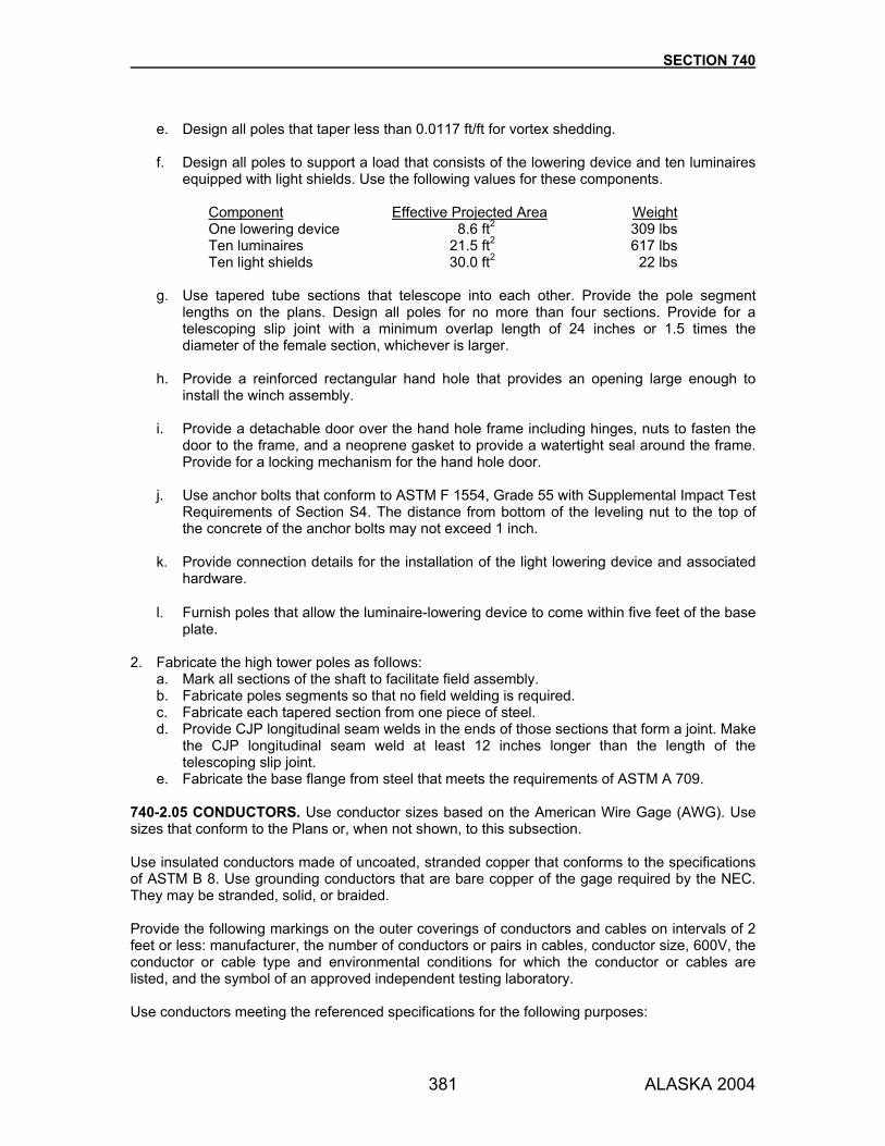
SECTION 740
381 ALASKA 2004
e. Design all poles that taper less than 0.0117 ft/ft for vortex shedding. f. Design all poles to support a load that consists of the lowering device and ten luminaires
equipped with light shields. Use the following values for these components.
Component Effective Projected Area Weight One lowering device 8.6 ft2 309 lbs Ten luminaires 21.5 ft2 617 lbs Ten light shields 30.0 ft2 22 lbs
g. Use tapered tube sections that telescope into each other. Provide the pole segment
lengths on the plans. Design all poles for no more than four sections. Provide for a telescoping slip joint with a minimum overlap length of 24 inches or 1.5 times the diameter of the female section, whichever is larger.
h. Provide a reinforced rectangular hand hole that provides an opening large enough to
install the winch assembly. i. Provide a detachable door over the hand hole frame including hinges, nuts to fasten the
door to the frame, and a neoprene gasket to provide a watertight seal around the frame. Provide for a locking mechanism for the hand hole door.
j. Use anchor bolts that conform to ASTM F 1554, Grade 55 with Supplemental Impact Test
Requirements of Section S4. The distance from bottom of the leveling nut to the top of the concrete of the anchor bolts may not exceed 1 inch.
k. Provide connection details for the installation of the light lowering device and associated
hardware.
l. Furnish poles that allow the luminaire-lowering device to come within five feet of the base plate.
2. Fabricate the high tower poles as follows:
a. Mark all sections of the shaft to facilitate field assembly. b. Fabricate poles segments so that no field welding is required. c. Fabricate each tapered section from one piece of steel. d. Provide CJP longitudinal seam welds in the ends of those sections that form a joint. Make
the CJP longitudinal seam weld at least 12 inches longer than the length of the telescoping slip joint.
e. Fabricate the base flange from steel that meets the requirements of ASTM A 709. 740-2.05 CONDUCTORS. Use conductor sizes based on the American Wire Gage (AWG). Use sizes that conform to the Plans or, when not shown, to this subsection. Use insulated conductors made of uncoated, stranded copper that conforms to the specifications of ASTM B 8. Use grounding conductors that are bare copper of the gage required by the NEC. They may be stranded, solid, or braided. Provide the following markings on the outer coverings of conductors and cables on intervals of 2 feet or less: manufacturer, the number of conductors or pairs in cables, conductor size, 600V, the conductor or cable type and environmental conditions for which the conductor or cables are listed, and the symbol of an approved independent testing laboratory. Use conductors meeting the referenced specifications for the following purposes:
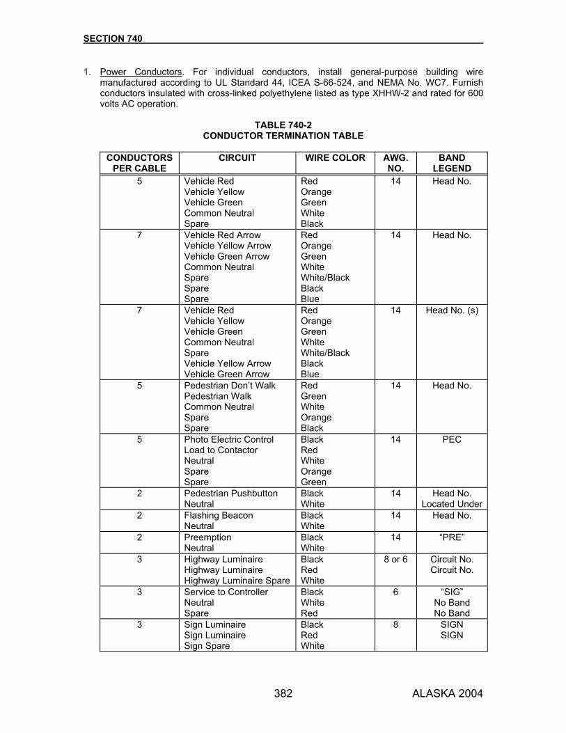
SECTION 740
382 ALASKA 2004
1. Power Conductors. For individual conductors, install general-purpose building wire manufactured according to UL Standard 44, ICEA S-66-524, and NEMA No. WC7. Furnish conductors insulated with cross-linked polyethylene listed as type XHHW-2 and rated for 600 volts AC operation.
TABLE 740-2
CONDUCTOR TERMINATION TABLE
CONDUCTORS PER CABLE
CIRCUIT WIRE COLOR AWG. NO.
BAND LEGEND
5 Vehicle Red Vehicle Yellow Vehicle Green Common Neutral Spare
Red Orange Green White Black
14 Head No.
7 Vehicle Red Arrow Vehicle Yellow Arrow Vehicle Green Arrow Common Neutral Spare Spare Spare
Red Orange Green White White/Black Black Blue
14 Head No.
7 Vehicle Red Vehicle Yellow Vehicle Green Common Neutral Spare Vehicle Yellow Arrow Vehicle Green Arrow
Red Orange Green White White/Black Black Blue
14 Head No. (s)
5 Pedestrian Don’t Walk Pedestrian Walk Common Neutral Spare Spare
Red Green White Orange Black
14 Head No.
5 Photo Electric Control Load to Contactor Neutral Spare Spare
Black Red White Orange Green
14 PEC
2
Pedestrian Pushbutton Neutral
Black White
14 Head No. Located Under
2 Flashing Beacon Neutral
Black White
14 Head No.
2 Preemption Neutral
Black White
14 “PRE”
3 Highway Luminaire Highway Luminaire Highway Luminaire Spare
Black Red White
8 or 6
Circuit No. Circuit No.
3 Service to Controller
Neutral Spare
Black White Red
6 “SIG” No Band No Band
3 Sign Luminaire Sign Luminaire Sign Spare
Black Red White
8 SIGN SIGN

SECTION 740
383 ALASKA 2004
Use size 10 AWG wire for illumination tap conductors. In an electrolier, the illumination tap conductors run from the fused disconnect kit to the ballast in the luminaire. Furnish conductors with black, red, or white colored insulation as required to identify the two phase and neutral conductors, respectively. If conductors in controller cabinets carry the full signal load circuit, use size 10 AWG or larger conductors. Use orange colored conductors from the flash transfer relay to program emergency flashing operation.
2. Illumination Cables. For cables that consist of three size 6 or 8 AWG conductors, furnish
power cables that feature three conductors, each insulated with cross-linked polyethylene, and a black, low density, high molecular weight polyethylene jacket. Use insulated conductors listed as type XHHW-2. Furnish these cables with one black, one white, and one red colored conductor and no grounding conductor. Use cables rated for 600 volts AC operation. Use insulated conductors meeting ICEA S-66-524 and UL Standard 44. The jacket must also meet ICEA S-66-524.
3. Power Cables. For cables that consist of three size 4 AWG and larger conductors, furnish tray cables that feature three conductors, each insulated with cross-linked polyethylene that meets the requirements of XHHW-2, and a PVC jacket. Furnish these cables without an integral grounding conductor. Use cables manufactured according to UL Standard 1277, ICEA S-95-658, and NEMA No. WC70. Provide cables listed for direct burial and resistance to sunlight and rated for 600 volts AC operation. Furnish these cables with black conductor insulation with one printed number (1, 2, or 3) identifying each conductor.
4. Control Cables. Wire with signal cable meeting IMSA 20-1 all vehicular signal heads, pedestrian signal heads, pedestrian push button detectors, flashing beacons, hardwired local coordination and preemption devices, and photoelectric controls.
5. Detector Loops. Use No. 12 AWG conductors for detector inductive loops that meet IMSA
Specification 51-3, Type RHW/USE, or IMSA Specification 51-5, when called for on the Plans or specified in the Special Provisions.
6. Loop Lead-In Cables. Unless otherwise specified, use a tray cable that conforms to the
following specifications to connect the loop detectors to the terminal blocks in the controller cabinet. Furnish this cable, also known as Snyder Cable; manufactured according to UL Standard 1277. Supply these cables third party certified as Type TC and certified for use in underground conduit or as an aerial cable supported by a messenger, and rated for 600 volts AC operation. Use size 18 AWG, 16 strand, tinned copper conductors per ASTM B-33 insulated with wet-rated, cross-linked polyethylene similar to XHHW. Furnish conductors with insulation colors that match Table 660-1 twisted into pairs. Provide each twisted pair with an overall aluminum foil coated mylar shield that provides 100% coverage and a 20 AWG tinned copper drain wire that is in constant contact with the foil side of the shield. Apply a tight fitting polyvinyl chloride jacket over the conductor assembly. Only use the following loop lead-in cable, also known as shielded data cable, to rewire existing traffic signals when specified. Use cables that consist of 6 twisted pairs that consist of stranded, size 18 AWG tinned copper wire and polyethylene or polypropylene insulation.

SECTION 740
384 ALASKA 2004
Furnish each pair covered with an aluminum foil shield, stranded copper drain wire, and an overall PVC or PE jacket. Use cable rated for 300 volts and whose colored pairs match those specified in Table 660-1.
7. Telemetry Cable. Use interconnect cable that consists of solid copper conductors of the number of pairs called for in the Plans meeting the requirements of Rural Utilities Service (formerly the Rural Electrification Administration (REA) specification PE-39 for filled telephone cables. The shield may be either copper or aluminum.
TABLE 740-3
INTERCONNECT TERMINATION TABLE
TELEMETRY CABLE: Type PE-39, No. 19 or No. 22 AWG, Solid Copper, as noted on the Plans or in the Special Provisions.
PAIR No. COLOR PAIR No. COLOR PAIR No. COLOR 1 Blue
White 9 Brown
Red 17 Orange
Yellow 2 Orange
White 10 Gray
Red 18 Green
Yellow 3 Green
White 11 Blue
Black 19 Brown
Yellow 4 Brown
White 12 Orange
Black 20 Gray
Yellow 5 Gray
White 13 Green
Black 21 Blue
Violet 6 Blue
Red 14 Brown
Black 22 Orange
Violet 7 Orange
Red 15 Gray
Black 23 Green
Violet 8 Green
Red 16 Blue
Yellow 24 Brown
Gray 25 Gray
Violet
HARDWIRE CABLES: IMSA Type 20-1, (2) 7 conductor No. 14 AWG Cable No. 1 Cable No. 2
Circuit Color Circuit Color Cycle 2 Green Offset 1 Green Cycle 3 Orange Offset 2 Orange Cycle 4 Red Offset 3 Red
Free Blue Split 2 Blue Common White Common White
Spare Black Spare Black Spare White/Black Spare White/Black
740-2.06 ELECTRICAL CONDUIT. 1. Rigid Metallic Conduit. Use UL Standard UL-6 galvanized conduit and fittings that are rigid
metal type and manufactured of mild steel or wrought iron. 2. Rigid Nonmetallic Conduit. Use UL Standard UL-651 Schedule 40 and 80 rigid polyvinyl
chloride (PVC) conduit. Use PVC fittings meeting NEMA TC 3.

SECTION 740
385 ALASKA 2004
740-2.07 FUSED SPLICE CONNECTORS. Use fused, quick disconnect, splice connector that is weather tight and has two halves: a single-unit line side socket and a load-side plug. Use fuses that are 10 ampere, midget (13/32” x 1-1/2“) ferrule type with a fast acting current limiting (KTK type) design. 740-2.08 SIGN SWITCHES. Provide a NEMA 3R non-fused disconnect switch as shown on the Plans for each sign illumination installation. 740-2.09 CONTROLLER ASSEMBLIES. Use solid-state, traffic controller assembly meeting the requirements of NEMA Standard. TS 1-1989, Traffic Control Systems, and designated sections of NEMA Standard TS 2-1992, Traffic Controller Assemblies. Use non-incandescent indicators for all electronic devices covered under Subsections 740-2.10 through 740-2.13. 740-2.10 CONTROLLER UNIT. 1. Actuated Controller Units. Actuated Controller Units must conform to the NEMA Standard TS
1-1989, Traffic Control Systems, Section 13 Interface Standards for Advance Two-Phase through 8-Phase Solid-State Traffic Controller Units and Section 14, Definitions and Physical and Functional Standards for Advance Two-Phase through 8-Phase Solid-State Traffic Signal Controller Units of the Vehicle-Actuated Type, and the following modifications:
a. Use single ring 4 phase or dual ring 8 phase controller units as shown on the Plans.
b. Make dual ring controller units user-programmable for dual entry and single-entry
operation.
c. TS 1-1989, Traffic Control Systems, 14.3.7.2 Overlap Programming. In item 1, insert “providing the function is field programmable without the use of external tools or devices” after the word “manufacturer”.
740-2.11 CONTROLLER CABINET. Use a controller cabinet that meets the requirements of NEMA Standard TS 2-1992, Traffic Controller Assemblies, Section 7, Cabinets and NEMA Standard TS 1-1989, Traffic Control Systems, Section 10, Terminals and Facilities. Apply 2 factory finishing coats of aluminum paint to the outside of the controller cabinets. Paint the interior surfaces of the controller cabinet with 2 factory finish coats of a suitable white exterior grade paint. 1. Standard Features. Supply the following standard features:
a. Cabinet Lock. Use a cabinet that has a main door equipped with a construction core lock. The lock must accept a Best CX series core that will be installed by the State after the contract is complete.
b. Cabinet Ventilation.
(1) Furnish the fan and cabinet vent with internally mounted metal covers that are
fabricated to close off the flow of air during winter operation.
(2) Equip the cabinet with a selectable, 750/1500-watt cabinet heating device. The heating device must have a remote air-sensing thermostat. The contacts must be rated 20 amps, 120 volts.
SECTION 740
386 ALASKA 2004
Construct the thermostat so that contacts close on descending temperature and are adjustable between 0 and 30 °F ±5 °F. The contacts must open on rising temperatures of 15 °F above the closing temperature. The adjustment must have an indicating pointer. Connect the thermostat in series with an electrical resistance heater and blower fan. The blower fan must be rated for continuous duty. The heater and fan must be connected in parallel and rated 120 volts, 60 Hertz. Mount the unit in the horizontal position at a location beneath the lowest shelf. Do not block the air intake or outlet. Provide the unit with a SPST manual override switch that bypasses the thermostat to enable the fan and heater to operate at warmer temperatures.
c. Cabinet Wiring. (1) Neatly arrange the wiring within controller cabinets to conform to the requirements of
Subsections 660-3.05 and 740-2.05.
Wire and equip all controller cabinets to handle the full capacity of the controller and cabinet configuration (see NEMA TS 1-1989, Traffic Control Systems, Section 10, Table 10-2 Wired Sockets) specified on the Plans or Special Provisions. Use configuration 4 for a 4-phase controller, and configuration 8 for an 8-phase controller.
Equip the cabinet with all required control and auxiliary equipment connecting cables to operate the phases and detection indicated on the Plans, including future use. Size all wiring, switches, surge protectors, flash relays, flashers, etc., to handle the necessary amperage required under full cabinet use. Use orange colored wires to run from the flash transfer relay used for emergency flash programming.
(2) Intersection flash operation must be programmable by rearranging interconnecting
jumpers between the load switches, flash transfer relays, and field signal wire terminal blocks. Make these changes by moving the jumpers at the terminal blocks.
(3) Field Terminal Blocks.
(a) Provide 2 or more insulated terminal blocks to terminate field conductors. Provide
each block with 12 poles with 10-32 screw type terminals. Use a terminal block that is a barrier type with removable shorting bars in each of the 12 positions and with integral-type marking strips. Terminate all conductors to a terminal block.
(b) Terminate conductors from the controller unit in ring-type terminal lugs or solder
them to a through panel solder lug on the rear side of the terminal. Terminate all other conductors in spade-type terminal lugs.
(c) Do not bring more than 3 conductors to any one terminal. Two flat metal jumpers,
straight or U shaped, may also be placed under a terminal screw. Fully engage at least 2 full threads of all terminal screws when the screw is tightened. Do not extend live parts beyond the barrier.
(d) Terminate all interconnect cable conductors on individual terminals.
(e) Include a 16-position neutral terminal bus bar on each side of the cabinet.

SECTION 740
387 ALASKA 2004
d. Cabinet Accessories. See NEMA Standard TS 2-1992, Section 5 Terminals and Facilities, Figure 5.4.2-1 Cabinet Power Distribution Schematic for items (1) through (5). (1) Disconnecting Means.
(a) Main circuit breaker must be a single pole, 50 ampere, 10,000 amperes
interrupting capacity for 8 phase cabinets or a single pole, 30 ampere, 10,000 amperes interrupting capacity for 4 phase cabinets.
(b) Auxiliary circuit breaker(s) must be single pole, 20 ampere, 10,000 amperes
interrupting capacity to protect fan, heater, light and convenience outlet(s). The rating of the main disconnect means with overcurrent protection must be not less than 125% of the maximum anticipated continuous load. When using disconnecting means, use the “trip-indicating trip-free” type.
(2) Signal Bus. Connect the signal bus to the incoming AC line through a signal bus mercury contactor and an overcurrent protection device. Energize the signal bus mercury contactor to provide power to the signal bus. The current rating of the signal bus mercury contactor must be at least the current rating of the main overcurrent protection device.
(3) AC Service Transient Suppression. Connect the transient suppression device for the
primary feed of the cabinet on the load side of the cabinet overcurrent protection device. The transient voltage suppression device connected to the controller power circuit must provide protection against voltage abnormalities of 1 cycle or less duration. The suppressor must be solid state high energy circuit containing no spark gap, gas tube, or crow bar component. The current rating of the device must be 15 amps minimum. The device must provide transient protection between neutral and ground, line and ground, as well as line and neutral. If the protection circuits fail, they must fail to an open circuit condition. The device must meet all requirements of UL standard 1449. The suppressed voltage rating must be 600 volts or less when subject to an impulse of 6,000 volt, 3,000 amp source impedance, 8.0/20 microsecond waveform as described in UL 1449. In addition, the device must withstand, without failure or permanent damage, one full cycle at 264 volts RMS. The device must contain circuitry to prevent self-induced regenerative ringing. There must be a failure warning indicator light which must illuminate when the device has failed and is no longer operable. The transient suppression device must withstand a 20,000 ampere surge current with a 8x20 microsecond (time to crest x time to second halfcrest) waveform 20 times at 3-minute intervals between surges without damage or degradation to the suppressor. Output voltage must not exceed 500 volts at any time during the test. Use a device that is a solid state, high-energy circuit with no spark gap, gas tube, or bar component.
(4) Radio Interference Suppression. Equip each traffic cabinet, flasher, and other current
interrupting device with a suitable radio interference suppressor installed at the input power point. Install the radio interference suppressor after the AC service transient suppression unit described in Subsection 740-2.11.1.d.(3). It must provide a minimum attenuation of 50 decibels over a frequency range from 200 kilohertz to 75 megahertz, when used with normal installations. The interference suppressor must be hermetically sealed in a substantial metal case filled with suitable insulating compound. Terminals must be nickel-plated, 10-24 brass studs of sufficient external length to provide space for connecting two No. 8 conductors and must be so mounted that the terminals cannot be turned in the case. Ungrounded terminals must be properly insulated from each other and must maintain

SECTION 740
388 ALASKA 2004
a surface leakage distance of not less than 1/4 inch between any exposed current conductor and any other metallic part, with an insulation factor of 100 to 200 megohms dependent on external circuit conditions.
The radio interference suppressor must have a current rating equal to, as a minimum, the rating of the main disconnect means as specified in Subsection 740-2.11.1.d.(1). It must be designed for operation on 120 volts, 60 hertz, single phase circuits and be UL and EIA compliant. Connect the ground connection of the radio interference suppressor only to AC neutral. Do not connect to Earth Ground directly.
(5) Light Fixture. Mount a fluorescent lighting fixture on the inside of the cabinet near the
front edge. Use a fixture rated to accommodate a F15T8 lamp operated from a high power factor ballast. The lamp must be included. The lighting fixture “ON-OFF” switch must be a toggle switch mounted on an inside control panel. Include in the circuit a door-actuated switch that turns the light ON when the door is open and OFF when the door is closed.
(6) Communications Transient Suppression. Provide a transient suppressor for the
system interface communications lines when used. This suppressor must withstand a 100 ampere 10 x 700 microsecond waveform 20 times at 30 second intervals between surges without damage or degradation to the suppressor. Apply the transient surge both line to line and line to ground. Output voltage must not exceed 8 volts line to line and line to ground. Output voltage must not exceed 8 volts line to line or 250 volts line to ground at any time during the test.
(7) Control Panel. Provide and label a control panel assembly that is readily accessible
from the front of the cabinet. The control panel assembly must consist of:
(a) “controller power” switch to energize the controller while the signal lights are off or are being operated by the flasher. Label and rate the switch for load current.
(b) convenience outlet with independent ground fault circuit protection. Use a duplex,
3-prong, NEMA Type 5-20R grounding type outlet.
(c) “auto/flash” switch which when placed in the “flash” position provides flashing operation without interrupting the controller unit power. When the switch is placed in the “auto” position the controller unit must provide normal operation.
(d) “stop time/off/on” switch which when placed in the “stop time” position causes the
controller unit to stop time. In the “off” position the controller unit must be active regardless of external commands. In the “on” position the timing must be normal but subject to external command interruptions.
(e) “heater by-pass” switch to by-pass the remote heater thermostat.
(f) momentary contact test switches to place calls on each vehicle and pedestrian
phase. Switches must provide tactile feedback and be rated at 1 ampere, minimum, for a resistive load at 120 volts AC and at 28 volts DC. Contacts must be coin silver or gold plated and be enclosed and labeled as to their function.
e. Police Panel Assembly. Provide a labeled police panel assembly located behind the
auxiliary door, consisting of:

SECTION 740
389 ALASKA 2004
(1) “flash/automatic” switch which when placed in the “flash” position causes the intersection displays to go into the flashing mode. When placed in the “automatic” position, the signal system must resume normal operation.
(2) “signals /off” switch which when placed in the “off” position removes power from the
signal bus. Do not allow power on the bus when either “automatic” or “flash” operation is selected by any means.
(3) removable, rigid metal cover on the back of the police panel to cover the live switch
terminals.
f. Warning Sign. The cabinet must contain a conspicuous warning sign against operation without the conflict monitoring device being installed.
2. Special Features. Provide special features if called for on the Plans or as specified in the Special Provisions.
a. Intersection Display Panel. Connect the display panel to the field wiring terminals, and
include the following features: (1) LED indicators for 8 vehicle phase displays (R-Y-G) (2) LED indicators for 4 pedestrian phase displays (W-DW) (3) A door activated switch that turns off the display panel when the cabinet door is
closed (4) Momentary detector tests switches to enter 8 vehicle phase calls and 4 pedestrian
phase calls (5) A display panel that is plug connected to the cabinet and is completely removable
without disconnecting individual wires (6) Approaches labeled with the street names and the northerly direction indicated
b. Manual Phase Selector Controls. Provide the traffic signal system with manual phase
selector control that permits the system to advance to any phase, including pedestrian indications, with all clearance periods timed by the controller units. Phases must be selected by a momentary contact switch, which plugs into a standard 1/4 inch 2-circuit telephone jack located in the police panel. Changes from “automatic” to “manual” phase selector control mode must be controlled by a toggle switch. Mount the toggle switch for the manual phase selector control in the police panel and clearly label it “Automatic/Manual.”
c. Coordination “Remote/Time of Day/Free” Switch. When the switch is in the “Remote” position, all supervisory functions performed on the controller unit from a master coordinator or central computer must operate normally. When the switch is in the “Time of Day” position, the local controller must use the local coordinators time of day plan. When the switch is in the “Free” position it must be possible to remove any or all coordination devices and maintain normal, non-coordinated controller operation without wire jumpers, jumper plugs or other special devices. Provide this switch if a local coordination or system modem/interface unit is shown on the Plans.
740-2.12 STANDARD AUXILIARY EQUIPMENT. 1. Solid State Flasher. Use a NEMA Type III flasher unit that conforms to NEMA Standard TS 2-
1992, Traffic Controller Assemblies, Section 6.3 Solid State Flashers.

SECTION 740
390 ALASKA 2004
2. Three-Circuit Solid State Load Switches. Use load switches that conform to NEMA Standard TS 2-1992, Traffic Controller Assemblies, Section 6.2 Three Circuit Solid State Load Switches and as a minimum be supplied with Light Emitting Diode indicators on the DC input circuitry. The load switch must have 3 independent switching circuits, each being an individually replaceable solid state module.
3. Conflict Monitors.
a. Use conflict monitors that are NEMA Type 12 with 12 fully programmable input channels.
b. Use a low impedance device external to the unit between the input and AC (Common) if the circuit connected to the sensing input of the unit exhibits high impedance characteristics caused by dimmers or burned-out lamps.
c. Use a unit that verifies each yellow change interval for a minimum display period of at least 2.7 ±0.1 seconds. The yellow change interval is the time which the yellow field terminal input is active. When the minimum yellow change interval is not satisfied, the conflict monitor must transfer the output relay contacts to the fault condition.
4. Flash Transfer Relay. Use flash transfer relays that meet the requirements of NEMA
Standard TS 2-1992, Traffic Controller Assemblies, Section 6.4 Flash Transfer Relays. 740-2.13 SPECIAL AUXILIARY EQUIPMENT. Use the following special auxiliary equipment when called for on the Plans and/or Special Provisions: 1. Inductive Loop Detectors. Provide inductive loop detectors that conform to the requirements
of NEMA Standard TS 1-1989, Traffic Control Systems, Section 15, Inductive Loop Detectors.
2. Local Coordination Units. Provide local coordination units that are solid-state, utilizing digital
timing. The units must be compatible with existing master systems.
a. Controls. Each coordination unit must provide the following minimum supervisory control of the local controller unit: (1) 3 cycles (2) 3 offsets for each cycle (3) Free Call results in independent operation of the local controller unit (4) 3 permissive periods (5) 3 split selections (6) Short direction offset seeking (7) Call to non-actuation during coordinated operation
b. Cycle. Adjustable over a minimum range of 40 to 150 seconds in a maximum of 5 second
increments. c. Offsets. Selectable as a percentage of the cycle length in 1% increments from 0% to
99%, or in 1 second increments. d. Free Call. By suitable connections at the local controller, the effect of “Free Call” may be
omitted. In this case, when the System Master calls for free operation, the local coordinating unit must operate to provide the shortest cycle and the associated average offset.

SECTION 740
391 ALASKA 2004
e. Permissive Periods. (1) First Vehicle Permissive. During this period, the coordinator must yield the controller
to the selected, non-actuated phase(s). The end of this period must be capable of being set at any 1% or 1 second interval.
(2) First Pedestrian Permissive. This period may be of fixed duration and must start
concurrently with the First Vehicle Permissive. It must terminate no more than 7% later. During this period, the coordinator must yield the controller to the selected, non-actuated vehicle plus pedestrian phase(s). When the coordinator yields to a vehicle during this period, the associated phase must be inhibited until the following cycle.
(3) Second Vehicle Permissive. Both the start and end of this cycle must be capable of
being set at 1% or 1 second increment of the cycle. During this period, the controller must respond to pedestrian and vehicle calls, for the pre-selected phases.
f. Force Offs.
(1) Equip the coordinator with 2 independent, ring-related, force off functions. (2) The force off function must cause the local controller to terminate the right-of-way of
the appropriate phase. (3) Force off points must be selectable to any 1% or 1 second increments of the cycle.
g. Offset Seeking. The coordination unit must seek any new offset in the shortest direction
at a rate not to exceed 20 percentage points per cycle. h. Call to Non-Actuation. The coordinator must provide an output that may be used to
energize the call to non-actuation and inhibit the maximum termination inputs to the local controller.
i. Connectors. Provide a front panel mounted, MS-type connector for all input/output circuit
connections.
3. System Modem/Interface Unit. Supply a system modem/interface unit assembly that is compatible with the existing computerized traffic control system.
4. Preemption Units. Provide preemption units that are solid-state with digital timing. Equipment
must be shelf-mounted, with a front panel MS-type connector. Design preemption equipment to use the controller functions and timing capabilities to the maximum extent. Installing the preemption equipment must not alter the internal wiring of the controller unit. The preemption units may be an integral part of the controller unit.
5. Special Logic.
a. Use special logic circuits that are solid-state with digital timing. b. Build solid-state logic or timing circuits (external to the controller unit) on edge-connected,
plug-in, printed circuit boards. Build up logic circuits by plugging logic circuit boards into wired connectors. When using 5 or less plug-in logic circuit boards, install the circuit board connectors in a chassis or rack mounted on a cabinet wall. Provide MS-type connectors to permit removal of the chassis or rack without unsoldering connections or removing wires or cables from the cabinet.

SECTION 740
392 ALASKA 2004
When using more than 5 plug-in logic circuit boards, install the circuit board connectors on a chassis designed for shelf mounting. Provide this chassis with a Type MS connector. It must be shelf-mounted.
c. Obtain approval when using special logic circuits before the controller cabinet and
equipment are fabricated by the supplier.
740-2.14 VEHICULAR SIGNAL HEADS. Conform to Chapter 2 of Equipment and Material Standards of the ITE (Publication ST-0017A), Vehicle Traffic Control Signal Heads (VTCSH). Each signal head must: be adjustable, vertical type with the number and type of lights specified; provide a light indication in one direction only; be adjustable through 360 degrees about a vertical axis; and be mounted at the location and in the manner shown on the Plans. Except for optically programmed signal heads, all vehicular signal heads at any one intersection must be of the same make and type. 1. Conventional Signal Heads. Use LED optical units for red and green indications. Use
incandescent optical units for yellow indications.
Provide a removable aluminum tunnel visor with an open slot at the bottom for each optical unit. When shown on the Plans or specified in the Special Provisions, construct the visor of polycarbonate resin with the color (black) pigment completely impregnated throughout the resin material. Factory finish signal heads, signal head mountings, brackets and fittings, and outside of visors with 2 coats of dark olive green enamel. Painting is not required where the color is an integral part of the component material. Factory finish signal visor interiors with 2 coats of flat black enamel. a. Incandescent Optical Units.
(1) Furnish each optical unit complete with lens, reflector, lamp holder, and clear
incandescent traffic signal lamp.
(2) Provide standard glass prismed traffic signal lenses.
(3) Secure the lamp holder to the reflector to provide a dust and moisture-proof seal.
(4) Hold the reflector and lamp holder securely in place with the outer edge of the reflector engaging the lens gasket to provide a light and moisture seal for the entire optical assembly.
(5) Wire all lamp holders so that a white wire will be connected to the shell of the lamp
holder and a black or colored wire to the bottom or end terminal of the lamp holder. Connect these wires, in turn, to the terminal block mounted inside at the back of the housing. The terminal block must have sufficient screw type terminals to terminate all field wires and lamp wires independently, with separate screws. Permanently identify the terminals to which field wires are attached or color-code the wiring to facilitate field work. Locate the terminal block in the center section of the head.
(6) Lamps for the 12-inch units must be 1,950 lumen minimum initial output, 120 volt,
6,000 hour rated life, clear, traffic signal lamps.
(7) Lamps for the 8-inch units must be 665 lumen minimum initial output, 120 volt, 6,000 hour rated life, clear, traffic signal lamps.

SECTION 740
393 ALASKA 2004
(8) Use reflectors made of Alzak finished aluminum. The thickness of the anodic coating must be a minimum of 0.0001 inches, or its equivalent, spun or drawn from metal not less than 0.025 inches thick and equipped with a bead or flange on the outer edge to stiffen the reflector to ensure it is held true to shape. The reflecting surface must be totally free of flaws, scratches, defacements, or mechanical distortion.
b. LED Optical Units. Use red and green LED signal modules that meet the requirements of
Chapter 2a of Equipment and Material Standards of the ITE (Publication ST-0017A), Vehicle Traffic Control Signal Heads (VTCSH2), and the following: Designed as retrofit replacement for existing optical unit of signal lamp and fits in the doorframe of a standard traffic signal section built to meet the VTCSH, without modification to the housing and not requiring on-site assembly or special tools for installation. Do not use incandescent lamp socket, reflector, reflector holder, or lens with an LED signal module. Single, self-contained, sealed unit with two conductors for connecting to power, a printed circuit board, power supply, a lens and gasket. Module must be weather proof after installation and connection and protect all internal components against dust and moisture intrusion according to NEMA Standard 250-1991 for Type 4 enclosures. Use a one-piece EPDM (ethylene propylene rubber) gasket to seal the module in the doorframe. Use AllnGaP technology and are the ultra bright type rated for 100,000 hours of continuous operation from -40 °F to 165 °F. Do not use AlGaS LEDs. Use wiring and terminal blocks meeting VTCSH Section 13.02. (1) Lens. The lens may be tinted or use transparent film or materials with similar
characteristics to enhance ON/OFF contrasts, provided that it does not affect chromaticity and is uniform across the face of the lens. If a polymeric lens is used, provide a surface coating or chemical surface treatment to the front surface to resist abrasion. Furnish modules with an integral lens that features a smooth convex outer surface made of ultraviolet stabilized plastic or glass. The lens must withstand ultraviolet (direct sunlight) exposure for a minimum period of 7 years without exhibiting evidence of deterioration.
(2) Photometric Requirements. Meet the following:
• Chromaticity coordinate requirements of VTCSH2, Section 4.2 • Luminous intensity values of VTCSH2, Section 4.1 after 72 months of continuous
use in a traffic signal system (3) Markings. Permanently mark the back of each LED signal module with:
• Manufacturer’s name, trademark, and other necessary identification • Warranty information • Rated voltage and power consumption in volt-amperes • An up arrow or the word “UP” or “TOP” for orientation within a signal housing
(4) Electrical. Operate from a 60 Hz (±3 Hz) AC line over a voltage range of 80 to 135
volts. The circuitry must prevent perceptible flicker over the voltage range specified above. The fluctuations of line voltage must have no visible effect on the luminous intensity of the indications. Rated voltage for all measurements must be 120 volts. Units must not produce light when the voltage drops to less than 45 volts AC.

SECTION 740
394 ALASKA 2004
Furnish each signal module with two secured, color-coded, 600 V, 20 AWG minimum, jacketed wires that conform to the NEC and are rated for service at +220 °F. Furnish 4-foot long conductors fitted with fork type terminal connectors. On-board circuitry must include voltage surge protection to withstand high-repetition noise transients as stated in Section 2.1.6 of NEMA Standard TS-2, 1992. The failure of an individual LED in a string must not result in the loss of the entire string or indication. LED signal modules must be operationally compatible with currently used controller assemblies (solid state load switches, flashers, and conflict monitors). LED signal modules and on-board circuitry must meet Federal Communications Commission (FCC) Title 47, Subpart B, Section 15 regulations concerning the emission of electronic noise. The LED signal module must provide a power factor of 0.90 or greater. Total harmonic distortion (current and voltage) inducted into an AC power line by a LED signal module must not exceed 20 percent.
(5) Production Testing Requirements. Require the manufacturer to energize each new
LED module for a minimum of 24 hours at operating voltage and at a temperature of 140 °F before shipment, to ensure electronic component reliability. After completing the burn-in procedure, require the manufacturer to test each LED lamp unit for rated initial intensity at rated operating voltage.
(6) Warranty. Provide a manufacturers written warranty that covers defects in materials
and workmanship for the LED signal modules for a period of 84 months. The warranty period will begin on the date the traffic signal satisfactorily completes the functional test prescribed in Subsection 660-3.01.7., Field Tests. The warranty period for modules that replace failed modules will begin on the date installed. Require the manufacturer to replace failed LED modules with new LED modules at no cost to the Department, including the cost of shipping failed modules. The warranty does not include the cost of removing failed modules from or reinstalling new modules in a traffic signal system. Require the manufacturer, upon notification a module has failed, to send, via next day delivery, the Department prepaid authorization to return the failed module. Require the manufacturer to deliver replacement LED modules, within 5 working days of receiving failed modules, to the location designated by the Department. Submit all warranty documents before installing the LED modules, including the manufacturer’s toll free telephone number for returning failed LED modules.
2. Programmed Visibility Signal Heads. Conform to the requirements for conventional signal
heads with incandescent optical units, except as modified below. Each signal section must provide a nominal 12-inch diameter circular or arrow indication. Meet the ITE Standard Specifications for color and arrow configuration. Provide each section with a 1-inch cutaway visor.
SECTION 740
395 ALASKA 2004
Provide each signal section with an adjustable connection that permits incremental tilting from 0 to 10 degrees above or below the horizontal while maintaining a common vertical axis through couplers and mounting axis in 5-degree increments. The signal must be mountable with ordinary tools and capable of being serviced without tools. Preset the adjustment at 4 degrees below the horizontal. The visibility of each signal face must be capable of adjustment or programming within the face. When programmed, each signal face’s indication must be visible only in those areas or lanes to be controlled. During dusk and darkness a faint glow to each side will be permissible. Before programming, each signal section with a yellow indication must provide a minimum luminous intensity of 3,000 candela on the optical axis, and a maximum intensity of 30 candela at 15 degrees horizontal from the axis. Each signal section must be capable of having its visibility programmed to achieve the following luminous intensities: a minimum of 3,000 candela on the optical axis, a maximum of 100 candela at from 1/2 to 2 degrees horizontal from the axis and a maximum of 10 candela at from 2 to 15 degrees horizontal from the axis. Under the same conditions, the intensities of the red indication and the green indication must be at least 19% and 38% respectively of the yellow indication. Each signal face or signal section must include integral means for regulating its luminous intensity between limits in proportion to the individual background luminance. Lamp intensity must not be less than 97% of uncontrolled intensity at 10,765 lux, and must reduce to 15±2% of maximum intensity at less than 10.8 lux. The dimming device must operate over an applied voltage range of 95 to 130 volts, 60 Hz and a temperature range of -40 °F to 165 °F. Program the head as recommended by the manufacturer and as directed by the Engineer.
3. Housing.
a. All parts of the housing, including the doors and end plates, must be of die cast aluminum meeting ASTM B 85, and all parts must be clean, smooth, and free from flaws, cracks, blow holes, or other imperfections.
b. The housing of each signal section must be one piece with integral top, bottom and sides,
with square doors.
c. All exposed bolts, screws, hinges, pins, and door locking devices must be stainless steel. All interior screws and fittings must be stainless steel or approved non-ferrous, corrosion-resistant material.
d. The top and bottom of each housing must have an opening to accommodate standard 1-
1/2 inch pipe fittings and brackets.
e. The top and bottom opening of the housing must have an integral serrated boss that will provide positive positioning of the signal head in 5-degree increments so as to eliminate undesirable rotation or misalignment of the signal head as well as between sections. A total of 72 teeth must be provided in the serrated boss. The teeth must be clean and sharp to provide positive positioning with the grooves of the mating section or framework.
f. Fasten together individual signal sections with a cadmium-plated tri-stud connector,
lockwashers, and nuts with access holes for the passage of electrical conductors from one section to another.

SECTION 740
396 ALASKA 2004
g. Each signal housing must have 2 integral hinge lugs located on the left side for mounting the door.
h. Provide 1 or 2 latches on the right side of each signal housing with stainless steel wing
nut assemblies to engage the door latches.
i. Each signal housing must have a door opening for the periphery with a soft closed cell neoprene gasket to provide a weather tight seal with the mating door.
j. Provide the door of each signal housing with a round opening designed to accommodate
any standard traffic signal lens. 4. Backplates. Furnish and attach backplates to all vehicle signal heads except post-mounted
flashers. Construct backplates of 0.051-inch minimum thickness aluminum alloy sheet meeting ASTM B 209, alloy 3003-H14. Backplates extensions for 12-inch displays must be 8 inches wide and for 8-inch display must be 5-1/2 inches wide. Where a backplate consists of 2 or more sections, fasten them together with aluminum rivets or bolts, peened after assembly to prevent loosening. All post mounted and pole side mounted vehicle signal heads must have 5 or 5-1/2 inch wide backplate extensions (borders). All 5 section overhead cluster mounted signals must have nominal 5-inch wide backplate extensions (borders). All combination 8-inch/12-inch vertical mounted signal heads must have backplates with nominal borders of 8 inches for the 8-inch sections and 5 inches for 12-inch sections. Factory finish the back faces of back plates with 2 coats of dark olive green enamel. Factory finish front faces of back plates with 2 coats of flat black enamel.
740-2.15 PEDESTRIAN SIGNALS. Conform to the ITE Standard for Adjustable Face Pedestrian Signal Heads. Use the international "HAND/WALKING PERSON" symbol. Use LED type message modules. 1. Signal Head Dimensions: Maximum overall dimensions of 18-1/2 inches wide, 18-3/4 inches
high, and 9 inches deep, including visor and hinges. 2. Message Symbols: Portland orange “HAND” and the lunar white “WALKING PERSON.”
Minimum of 12 inches high and 7 inches wide. 3. Message Module: Supply LED modules that display the “HAND” and WALKING PERSON”
symbols that comply with ITE Pedestrian Traffic Control Signal Indications (PTCSI) standard for these symbols. Furnish LED pedestrian signal modules designed as retrofit replacements for existing neon type pedestrian signals (ICC 4090 and/or 4094).
Furnish LED pedestrian signal modules that use AllnGaP technology and are the ultra bright type rated for 100,000 hours or more at 77 °F and 20 mA. Do not use AlGaS LEDs. Ambient operating temperature range of -40 F° to +140 °F.
Furnish one piece, self-contained, LED pedestrian signal modules that require no on-site assembly for installation in existing pedestrian signal housings. Furnish LED pedestrian signal modules designed to protect all internal LED, electronic, and electrical components against dust and moisture intrusion, when properly installed with gasket, and meet the requirements of NEMA Standard 250-1991, sections 4.7.2.1 and 4.7.3.2, for type 4 enclosures.
SECTION 740
397 ALASKA 2004
Furnish pedestrian LED traffic signal modules to replace neon type message modules found in 18-1/2 inch by 18-3/4 inch pedestrian signal housing built to the PTCSI Standard. Furnish LED modules that maintenance personnel can remove from the housing without damaging the module. The LED pedestrian signal modules must not require special tools for installation. LED pedestrian signal modules must fit into the existing pedestrian signal housings built to the PTCSI standard without any modifying the housing. Furnish LED pedestrian signal modules that fit securely in the housing, connect directly to existing electrical wiring, and form a weather-tight seal. Retrofitting an existing pedestrian signal must only require the removal of the existing neon message module, gasket, and power supply and installation of the new LED module. Each retrofit must include all necessary components to complete conversion including a one-piece gasket. Each pedestrian module must have a sticker attached stating compliance to the ITE Standard for color.
a. Lens. Furnish LED pedestrian signal modules with field-replaceable UV stabilized
polycarbonate lenses. The exterior of the lens must be smooth and frosted to prevent sun phantom.
b. Photometric Requirements. Furnish LED pedestrian signal modules that, when operated
over the specified ambient temperature and voltage range, pedestrians can read both day and night at all distances from 10 feet to the full width of the crossing. Meet the chromaticity coordinate of requirements of PTCSI Section 5.3 and Figure C. Luminous intensity must not vary more than +10% for voltage range of 80 to 135 VAC.
c. Markings. Meet the requirements of Subsection 740-2.14.1.b.(3).
d. Electrical. Meet the requirements of Subsection 740-2.14.1.b.(4). e. Production Testing Requirements. Meet the requirements of Subsection 740-2.14.1.b.(5). f. Warranty. Meet the requirements of Subsection 740-2.14.1.b.(6).
4. Housing.
a. Provide a dustproof and weatherproof housing that allows easy access to and replacement of all components.
b. Provide a one-piece, corrosion-resistant, aluminum-alloy die-cast case complete with
integrally cast top, bottom, sides and back. Provide 4 integrally cast hinge lug pairs, 2 at the top and 2 at the bottom of each case, for operation of a swing-down door.
c. Provide 3 versions of the case. The first and second versions need not include upper and
lower openings, but when provided must be plugged to be weather-tight.

SECTION 740
398 ALASKA 2004
(1) clamshell mount, with hardware, for installation of “pole left of message”
(2) clamshell mount, with hardware, for installation of “pole right of message”
(3) suitable for either post top or bracket mounting with upper and lower openings to accommodate standard 1-1/2 inch pipe brackets. Integrally cast a shurlock boss into the bottom opening of the signal case. Make the dimensions of the shurlock boss as follows: outside diameter, 2.625 inches; inside diameter, 1.969 inches; number of radial teeth, 72; and depth of teeth, 5/64 inch. The teeth must be clean and sharp and provide full engagement to eliminate rotation or misalignment of the signal.
d. Make the door frame a one-piece, corrosion-resistant, aluminum-alloy die-casting,
complete with 2 hinge lugs cast at the bottom and 2 latch slots cast at the top of each door. Attach the door to the case by means of two Type 304 stainless steel spring pins. Attach 2 stainless steel hinged bolts with captive stainless steel wingnuts and washers to the case with the use of stainless steel spring pins. The door must latch and unlatch without the use of tools.
5. Conductors. No. 14 AWG or larger meeting IMSA specifications 20-1. 6. Place all load switches for operation of the “WALK/WALKING PERSON” signals in the
controller cabinet. 7. Use machine screws, studs, and washers that are stainless steel. 8. Use gaskets that conform to ASTM D 1056, Grade 2C2. 9. Mount a terminal block in the unit for field wiring, as specified in Subsection 740-2.14. 10. Factory finish the outside of pedestrian signal head housings and visors with 2 coats of dark
olive green enamel. Painting is not required where the color is an integral part of the component material. Factory finish signal visor interiors with 2 coats of flat black enamel.
11. Pedestrian signals must show the following:
a. Steady “WALKING PERSON” during the pedestrian interval b. Flashing “HAND” during the pedestrian clearance interval c. Steady “HAND” after the pedestrian clearance and during the associated yellow and all
red vehicle clearance phase intervals d. Dark during intersection flash
740-2.16 PEDESTRIAN PUSH BUTTONS. Tamper-proof with a 2-inch minimum diameter concave or convex chrome or stainless steel telescoping-type plunger. Construct a weatherproof assembly designed to prevent an electrical shock under any weather condition and grounded per the NEC. Push button switch. Provide a phenolic-enclosed precision snap-acting type, switching unit, single-pole, double-throw, with screw type terminals, rated 15 amperes at 125 volts, AC. Must have the following characteristics: 1. Switching unit with a stainless steel plunger actuator and a U-frame to permit recessed
mounting in push button housing. 2. Switch operating force of 9 to 13 ounces and a minimum release force of 4 ounces.

SECTION 740
399 ALASKA 2004
Where a pedestrian push button is to be attached to a pole, shape the housing to fit the curvature of the pole to provide a rigid installation. Provide saddles to make a neat fit. Where a pedestrian push button is to be mounted on top of a 2-1/2 inch diameter post, provide the housing with a slip-fitter with screws for securing to the post. Factory finish pedestrian push button housings, mountings, brackets and fittings with 2 coats of dark olive green enamel. Painting is not required where the color is an integral part of the component material. 740-2.17 FLASHING BEACONS. Each beacon consists of a single section traffic signal head, meeting the provisions in Subsection 740-2.14 with yellow or red lens as shown on the Plans. Each flashing beacon control unit consists of a circuit breaker, flasher, and terminal block housed in a single enclosure. Provide a NEMA Type 3R enclosure with top-hinged cover, hasp for sealing cover, and provisions for locking. Furnish and install a radio interference and transient suppressor in the enclosure, meeting the requirements of Subsection 740-2.11.1.d.(3) and (4). Mount 20 amp, single-pole, 120 volt AC switches at the top and center of the dead front panel. Use a solid state NEMA Type 3 flasher meeting the requirements of NEMA Standard TS 1-1989, Traffic Control Systems. Use 20 amp, 600 volt barrier-type terminal blocks, molded from phenolic material, with plated brass screw-type terminals and integral-type marking strips. 740-2.18 LUMINAIRES. 1. Mast Arm Mounted Luminaires.
Furnish luminaires that: a. Have high pressure sodium lamps with a rated life of 24,000 hours based on 10 hours
per start b. Include a terminal block for terminating the illumination tap conductors c. Feature an easily removed hinged door or tray used exclusively for mounting the ballast d. Provide the illumination levels and uniformity specified (or better) in the arrangements
listed on the Plans when calculated according to the American National Standard Practice for Roadway Lighting, A.N.S.I./I.E.S RP-8, dated 1983
e. Include a lamp-starting aid that plugs into a socket for easy replacement f. Feature a wire way meeting NEC requirements for installing three size 10 AWG
conductors with type XHHW-2 insulation between the pole and a terminal block located in the luminaire
g. Have reflectors free of substances (such as paint) that affect photometric performance Furnish the Engineer with manufacturer’s current electronic photometric data in Illuminating Engineering Society (I.E.S.) format to verify illumination levels and uniformity ratios. Provide mast arm mounted luminaires with slip-fitters designed for mounting on 2-inch nominal diameter standard pipe. Use refractor-type lenses made of borosilicate glass, unless polycarbonate resin refractors are called for in the Plans or Special Provisions.
SECTION 740
400 ALASKA 2004
When polycarbonate resin lenses are called for, mold the lens in a single piece from polycarbonate resin when approved for use by the manufacturer. Do not use reworked compound whose properties have been impaired by previous molding operations. Use lenses free from cracks, blisters, burns, and flow lines, and furnished with the natural molded surface. Lenses must be of uniform density throughout and be free from air, gas, or moisture pockets, and uncured areas, as consistent with good manufacturing practice. Lenses must be transparent with a clear bluish tint, produced from resin which has been suitably ultraviolet stabilized to reduce the effects of ultraviolet radiation on their color properties. Use resins which meet the requirements for the self-extinguishing classification of ASTM D 635. Resin must have a minimum impact strength, Izod notched of 12 foot-pounds per inch when tested according to ASTM D 256, Method A, using a 1/8 inch x 1/2 inch bar molded according to ASTM recommended practice. Furnish a certificate of compliance from the lens fabricator that all requirements contained in the paragraph above have been met. Mount the refractor in a door frame assembly which is hinged to the luminaire at the house side and fastened at the street side with an automatic type latch. Force the refractor and door frame assembly upward at the street side by spring pressure, against the gasket seat, when in the closed and latched position. Gasket material must be capable of withstanding the temperatures involved and be securely held in place. Manufacture all parts of the luminaire from corrosion-resistant materials. When cut off fixtures are specified, the optical assembly must provide 90-degree cutoff and shielding; consist of a die cast aluminum lens holder with a aluminum alglas finish, hydroformed gasketed reflector, and a heat impact resistant mogul multiple screw shell socket with lamp grips. Provide an adjustable socket holder with 2 vertical positions. Furnish an activated charcoal filter in the optical assembly to prevent particulate and gaseous contamination. Use a reflector that is specifically designed to produce an ANSI, IES (MC-III, S-C-II) light distribution when used with 200 through 400 Watt High Pressure Sodium lamps. Use a flat plate glass lens on the fixture. No part of the lens may project below the metal housing of the luminaire. Submit the manufacturer’s luminaire specifications and photometric data for approval, per Subsection 660-2.01.
2. High Tower Luminaires. Use luminaires with 480-volt, 1,000-watt, high pressure sodium lamps. Lamps must provide 140,000 minimum initial lumens with a rated life of 24,000 hours. Provide luminaires with double fused ballasts. Furnish fuses of the size recommended by the luminaire manufacturer. Use a filtered design fixture with borosilicate glass refractor. Use a reflector with a smooth, non-porous inner surface, encased within a spun and sealed aluminum cover. Firmly attach the reflector with aluminum cover to a cast ring. The ring must be designed so that the reflector/refractor assembly may be readily attached to, or detached from, the luminaire bracket entry and lamp support assembly without completely removing the support bolts. Enclose the luminaire ballast within a die-cast aluminum housing that integrally attaches to the luminaire bracket entry and lamp support assembly. It must be readily removable without removing the luminaire from the bracket arm. Furnish the assembly with a side entry slipfitter designed for 2-inch nominal diameter pipe with provision for ±3 degree adjustment for leveling the luminaire. Prevent the lamp from

SECTION 740
401 ALASKA 2004
backing out by means of a stainless steel lamp clamp attached to the assembly but separate from the socket. Include an enclosed terminal block which protects all electrical connections from exposure to weather. Attach an aluminum rolled rain shield to the outside of this assembly. Furnish the luminaire distribution type shown on the Plans or specified in the Special Provisions. Submit manufacturer’s luminaire specifications and photometric data for the fixture for approval prior to ordering.
740-2.19 SIGN LIGHTING FIXTURES. 1. Incandescent Down Light. Provide the type of sign lighting fixture, with incandescent lamp,
shown on the Plans or as specified in the Special Provisions.
a. Hood. Cadmium plated, finished with aluminum paint, and side outlet tapped for conduit.
b. Reflector. Symmetrical 8-inch steel. Porcelain enameled green finish on the outside and white on the inside.
c. Lamp. Provide 2,900 lumen. 2. Mercury Vapor. Fully enclosed, rain-tight, dust-tight, and corrosion-resistant. Design each
fixture for mounting at the bottom of the sign on an overhead sign structure as shown on the Plans. Painting of fixture is not required.
a. Housing. Cast aluminum alloy or other non-corrosive material conforming to the Plans.
Finish all housings in a workmanlike manner with no exposed burrs or sharp edges.
b. Refractor. Glass having inner prisms with a smooth exposed face. Mount the refractor in a door frame assembly which is hinged to the body of the fixture and fastened with an automatic type latch.
c. Gaskets. Made of a material capable of withstanding the temperatures involved, and
securely held in place.
d. Light Distribution. Light distribution over the sign face must conform to the isolux distribution patterns shown in the Plans. Accomplish light distribution entirely by refraction through the lens with no additional refractors or reflectors.
e. Miscellaneous. All ballasts, lampholders, lamps, terminal blocks, and necessary fuses
must conform to applicable requirements of Subsection 740-2.21 or to the Plans.
f. Lamps. Color-improved to provide good color rendition of signs. 740-2.20 ILLUMINATION CONTROL. Use photoelectric controls capable of directly switching multiple lighting systems. Furnish photoelectric units designed for pole top mounting which include a slip-fitter, terminal block, and cable supports or clamps to support pole wires. 1. Photoelectric Unit. A light sensitive element connected directly to a normally closed, single-
pole throw control relay without intermediate amplifications. Plug the unit into a phenolic resin twist lock receptacle set in a cast aluminum mounting bracket with a threaded base. Screen photoelectric units to prevent artificial light from causing cycling.
Use either horizontal sensing or zenith sensing type units meeting the following: a. A supply voltage rating of 60 Hz, 105-277 volts b. A maximum rated load at a minimum of 1,800 volt-amperes c. An operating temperature range from -40 °F to +150 °F d. A power consumption of less than 10 watts

SECTION 740
402 ALASKA 2004
e. A unit base with a 3-prong, EEI-NEMA standard, twist-lock plug mounting Furnish units for highway lighting that have a “turn-on” between 10.8 and 54 lux and a “turn-off” at between 1.5 and 5 times “turn-on.” Furnish units for illuminated signs that have a “turn-on” level of between 215 and 270 lux. (“Turn-on” level specified above corresponds to a switching level of approximately 430 to 540 lux measured in the horizontal plane.) "Turn-off" level must not exceed 3 times “turn-on” level. Measurements must meet the procedures in EEI-NEMA Standards for Physical and Electrical Interchangeability of Light-Sensitive Control Devices Used in the Control of Roadway Lighting.
2. Temperature Switch. When mercury vapor sign lighting fixtures are used, provide a temperature switch in each photoelectric control circuit for lighting systems which will:
a. bypass the photoelectric unit when the ambient temperature drops to -13 °F, and
energize the mercury vapor light circuits; b. return switching functions to the photoelectric unit upon a temperature rise of 5 to 10 °F
above the turn-on temperature; and c. have a minimum range of (-40 °F to +40 °F), and be setable in increments no greater
than 5 °F. 740-2.21 BALLASTS. Include ballasts for high intensity discharge lamps as an integral part of each luminaire and design for the voltages and lamp types specified in the Plans or Special Provisions. Ensure that the current needed to start the lamps is less than the operating current. Furnish regulator-type ballasts with copper windings electrically isolated from each other, which will start and operate the lamps in temperatures down to -40 °F. The allowable line voltage variation is plus and minus 10%. Equip high-pressure sodium luminaires, except those with 1000 watt lamps, with magnetic regulator ballasts with the following additional operating characteristics: 1. The lamp wattage regulation spread at any time over the life of the lamp must not exceed
18% of nominal lamp watts at plus and minus 10% line voltage variations. 2. With nominal line and lamp voltages, the ballast must regulate the lamp output to within 5%
of the ballast design center, and sustain lamp operation with a minimum 60% voltage drop lasting 4 seconds or less.
Equip luminaires with 1000 watt high pressure sodium lamps with auto-regulator ballasts that provide a maximum 30% lamp regulation spread, a minimum 35% voltage dip tolerance, and with nominal line and lamp voltages regulate lamp output to within 5% of the ballast design center. Furnish ballasts, for soffit luminaires, with mounting brackets attached and equip with terminal blocks for primary connections and lamp socket preconnected to the secondary for flush mounted luminaires and with terminal blocks for both primary and secondary connections for use with suspended luminaires. Submit the ballast manufacturer’s specification sheets for review and approval.

SECTION 740
403 ALASKA 2004
740-2.22 HIGH TOWER LUMINAIRE LOWERING SYSTEM. Furnish an integral luminaire lowering device that is compatible with the high tower design and consists of a head frame assembly, luminaire ring assembly, and winch assembly complete with electric motor. Provide a manufacturer’s on-site installation technician to oversee the assembly and final adjustment of all lowering system components. Furnish a complete service manual with instructions on installation, operation, and maintenence for each lowering device, winch assembly, and power drive system furnished on the project. Install one of the following high mast lowering devices wired for a single circuit, rated 480 VAC single-phase, on each high tower pole shown on the Plans. Furnish all power cords with four #8 AWG conductors.
Manufacturer Model No. Options to be furnished Eagle High Mast Lighting Co. ELC-XX-GV Hot dip galvanized masthead assembly
and transition plate, and integral motor Holophane Corporation LD25 Stainless steel hoist and winch cables Millerbernd Manufacturing SSLD-2 Integral winch and motor assembly
The Plans will indicate the number of luminaires on each pole, each pole’s height, and whether FAA approved obstruction lights are required. 740-2.23 UNDERPASS LIGHTING SYSTEM. Use underpass luminaires that have vandal-resistant surface-mounted fixtures installed in a galvanized welded steel enclosure as detailed on the Plans. The lamp must be a mogul based 150-watt, clear, ANSI/NEMA C78.1355, horizontal mount, high pressure sodium type. The lamp must provide a minimum of 15,000 initial lumens with a rated life of 24,000+ hours based on a minimum burn period of 3 hours. Mount the ballast within the body of the fixture with a constant wattage autoregulator CWA type meeting ANSI/NEMA C78.1355 operating characteristics. See Plans for input voltage. Provide a square lens that is semi-recessed, extra thick, injection molded polycarbonate prismatic type, with internal specular aluminum reflector. The lens must provide the uniformity specified in the Plans or Specifications with a minimum spacing to mounting height ratio (S/MH) of 3.5:1, in the plane defined by the axis of the lamp, and a minimum S/MH ratio of 1:1 in the plane passing vertically through the length of the lamp axis. Provide a lens frame and side housing made of ASTM B 209, alloy 6061-T6 tempered aluminum a minimum of 0.177 inch thick, or equivalent stainless steel, secured with tamper proof screws requiring a special manufacturer’s tool to remove. Provide fixtures that are Third Party listed for wet, damp, and dry locations. Fasten the fixture into the mounting enclosure with stainless steel screws accessible only from within the fixture housing. Fabricate the mounting enclosure from 0.138 inch thick mild steel with continuous welded seams and hot-dipped galvanized, as detailed on the Plans. Use wiring within the enclosure that might come in contact with the ballast rated at 390 °F [type SR-2]. Provide a grounding screw or lug within the enclosure for a maximum No. 8 AWG ground conductor. Submit the manufacture’s fixture specifications, photometric data, and a computer-generated lighting layout for approval prior to ordering. Calculate, by the point-to-point method, the light level

SECTION 740
404 ALASKA 2004
on the walkway surface through the underpass with no wall, ceiling, or walkway reflectances. The calculated light level on the walking surface and the calculated average-to-minimum uniformity ratio may not be worse than the light level and uniformity ratio noted on the drawings. Center the calculation area on the light fixtures and base it on the width of the walkway less 12 inches, and the length of the walkway equal to the distance between the first and last fixtures plus a distance equal to 50% of the spacing between the fixtures added to each end of the walkway. You may substitute fixtures having similar construction, electrical, and light distribution characteristics, if approved. In the case of a substitution, construct the enclosure shown on the drawing to match the mounting requirements of the submitted fixture. Submit shop drawings for the enclosure for approval along with the fixture shop drawings.
405 ALASKA 2004
INDEX
A Page Acceptance
of bid...........................................................................................................................................2 of materials......................................................................................................................... 31-36 of work................................................................................................................................45, 46 partial..................................................................................................................................28, 45 final........................................................................................................................ 29, 40, 48, 67 final........................................................................................................................ 29, 40, 48, 67 substantial completion....................................................................................... 7, 28, 45, 52, 53 testing.................................................................................................................................32, 35
Acronyms..........................................................................................................................................1 Active voice.......................................................................................................................................1 Addenda
definition of.................................................................................................................................2 requirements ............................................................................................................................11
Adjustment and Disputes, Claims for .......................................................................................29, 30 Administrative Permit Manual.........................................................................................................28 Admixture
air-entraining ................................................................................................. 119, 121, 176, 354 chemical .........................................................................................................................119, 354 concrete .................................................................................................................................354 for topsoil................................................................................................................................371 microsilica .............................................................................................................. 175, 176,354 retarding .........................................................................................................................190, 354 water-reducing ...................................................................................................... 122, 176, 354
Advertisement...............................................................................................................................2, 4 Aggregate Base and Surface Course.............................................................................................86 Aggregate for
concrete .................................................................................................................................343 base and surface course........................................................................................................343 asphalt concrete pavement....................................................................................................344 cover coat and surface treatment ..........................................................................................345 mineral filler............................................................................................................................345 selected material ....................................................................................................................346 filter blanket............................................................................................................................346 subbase..................................................................................................................................346 porous backfill ........................................................................................................................347 gabion backfill ........................................................................................................................347 sand blanket...........................................................................................................................347 subgrade modification..............................................................................................................88 riprap ......................................................................................................................................226
Air Entraining Agents....................................................................................................................124 Alaska Test Methods / Manual ....................................................................................................1, 2 Alaska Traffic Manual .................................................................................................. 291, 336, 357 Altered Quantities, Compensation for ............................................................................................64 Anchorages.................................................................................................. 141, 142, 189, 194, 368 Anchor Bolts ........................134, 141, 146, 157, 161, 232, 241, 306, 314, 316, 317, 365, 379, 381 Anchor Wire ..................................................................................................................................353 Anti-Strip Additives .......................................................................... 93, 95, 101, 102, 106, 110, 345

Page
406 ALASKA 2004
Appeals...............................................................................................................................30, 56, 57 Approved Products List ......................................................................................... 31, 173, 311, 333 Archaeological or Historical Discoveries ........................................................................................43 Arrow Panels ............................................................................................................... 291, 294, 297 Asphalt
application ............................................................................... 95, 112, 113, 115, 117, 272, 341 cement ............................................................................................ 93, 101, 220, 222, 272, 341 compaction................................................................................... 94, 96, 98, 104, 174,221, 223 cut-back..................................................................................................................................341 emulsified .......................................................................................... 95, 98, 113, 116, 117, 341 materials.........................................................................................................................341, 342 mixing.................................................................................................................. 93, 95, 98, 103 pavers.............................................................................................................................102, 103 plants................................................................................................................... 93, 95, 96, 102 preparation of surface ................................................................................... 103, 112, 113, 115 price adjustment............................................................................................................. 105-111 prime coat ..................................................................................................... 103, 113, 117, 341 rollers............................................................................................. 93, 94, 96, 98, 103, 104, 115 seal coat.........................................................................................................................115, 117 spreading equipment..........................................................................................................93, 96 spreading and finishing ...................................................................................... 94, 96, 103-105 surface treatment ...................................................................................................................117 storage ...................................................................................................................................103 tack coat.................................................................. 94, 103, 105, 110, 112, 272, 341, 342, 360 treated base course (ATB).......................................................................................................93
Asphalt Concrete Pavement aggregates ............................................................................................................ 101, 107, 344 composition ....................................................................................................................100, 101 construction requirements.............................................................................................. 102-105 price adjustment............................................................................................................. 105-111 surface tolerance....................................................................................................................105 temperature............................................................................................................................106
Assignment of Contract ............................................................................................................47, 53 Audit..........................................................................................................................................22, 57 Authority of
Contracting Officer .....................................................................................................................3 engineer ...............................................................................................................................4, 22 superintendent ...................................................................................................................23, 49 inspector...............................................................................................................................4, 27 EEO officer and DBE officer ....................................................................................................49 safety officer.......................................................................................................................42, 49
Award definition of.................................................................................................................................2 contract ....................................................................................................................................14 intent...................................................................................................................................14, 17
B
Backfill
conduits and minor structures..................................................................................................80 culverts and storm drains.........................................................................................................80 curbing ...................................................................................................................................223 electrical conduit ............................................................................................. 80, 242, 296, 318 excavation ................................................................................................................................77 gabion.............................................................................................................................277, 347

Page
407 ALASKA 2004
grubbing ...................................................................................................................................69 guardrail posts........................................................................................................................215 manholes and inlets .........................................................................................................80, 211 plant materials........................................................................................................................250 poles.......................................................................................................................................327 porous ..................................................................................................... 83, 185, 186, 212, 347 riprap ......................................................................................................................................226 sanitary sewers ......................................................................................................................261 sign posts ...............................................................................................................................232 structural plate pipe................................................................................................................206 structures ................................................................................................ 82, 139, 185, 195, 316 structures and obstructions......................................................................................................71 underdrains ............................................................................................................................212 water system..........................................................................................................................263
Backplates ................................................................................................................... 315, 328, 396 Ballast .......................................................................................... 242, 263, 293, 311, 323, 400, 402 Bankruptcy..........................................................................................................................13, 17, 53 Barbed Wire..........................................................................................................................218, 353 Barricades............................................................................................. 215, 251, 291, 293, 295-304 Barrier, Portable Concrete............................................................ 193, 291, 293, 295, 297, 301-304 Base Course
aggregate ...................................................................................................... 86, 93, 95, 98, 280 asphalt treated .........................................................................................................................93 crushed asphalt........................................................................................................................98 emulsified asphalt treated ........................................................................................................95
Batching asphalt concrete.....................................................................................................................103 microsilica modified concrete.................................................................................................178 plants......................................................................................................... 47, 95, 107, 121, 123 portland cement concrete.......................................................................................................124
Beam Rail .................................................................................................................... 214, 215, 353 Bearings
girder ......................................................................................................................................139 Teflon coated .........................................................................................................................149 setting.....................................................................................................................................156
Bedding............................................................................ 80, 82, 206, 207, 212, 242, 261, 263, 307 Best Management Practices.................................................................................................280, 362 Bid
bond ...............................................................................................................................2, 10, 14 consideration of........................................................................................................................13 definition of.................................................................................................................................2 delivery of.................................................................................................................................11 form ...................................................................................................................................... 9-11 guaranty (security) .............................................................................................. 2, 9, 10, 14, 17 guaranty, return of....................................................................................................................14 package......................................................................................................................................9 preparation of ...........................................................................................................................10 protest of ............................................................................................................................11, 13 receipt and opening of..............................................................................................................11 rejection of....................................................................................................................10, 13, 14 responsive/nonresponsive ...................................................................................... 6, 10, 11, 13 unauthorized additions, conditions or alternatives...................................................................10 withdrawal or revision of.....................................................................................................11, 13
Bidder definition of.................................................................................................................................2 disqualification of................................................................................................................11, 12

Page
408 ALASKA 2004
registration ...........................................................................................................................9, 47 qualification of ............................................................................................................................9
Bidding requirements and conditions ...............................................................................................9 Bid Schedule, Interpretation of Quantities in ....................................................................................9 Blasting
abrasive..........................................................................................................................160, 201 controlled..................................................................................................................................75 laws, regulations, permits, notices and liability ........................................................................43 plan...........................................................................................................................................75 production ................................................................................................................................76 sand........................................................................................................................................173 water.......................................................................................................................................177
Blind Drains ..................................................................................................................................212 Block
concrete masonry...........................................................................................................210, 347 sodding...................................................................................................................................258 terminal ...................................................................................................317-329, 334, 383-398 thrust ..................................................................................................................... 263, 264, 266
Blotter Material......................................................................................................................113, 117 Bolt
holes...................................................................................................... 152, 161, 167, 237, 353 length..............................................................................................................................153, 154 tension....................................................................................................................................154
Bolted Connections ..............................................................................................................153, 208 Bolts
anchor ...................134, 141, 146, 157, 161, 232, 241, 306, 314, 316, 317, 324, 365, 379, 381 high-strength ................................................................................. 153, 155, 161, 162, 364, 369
Bond bid...................................................................................................................................2, 10, 14 performance and payment .......................................................................... 5, 14, 15, 29, 47, 65
Bonding electrical systems.................................................................................................. 315, 319, 323 steel........................................................................................................................................144
Borrow ............................................................................................... 19, 47, 74, 75, 77, 78, 79, 257 Breakaway
cable terminal assembly.........................................................................................................216 sign post base ................................................................................................................231, 232
Brick......................................................................................................................................210, 347 Bridge
deck........................................................... 7, 104, 107, 119, 130, 132, 173, 174, 181, 182, 193 definition of.................................................................................................................................3 forms and falsework ............................................................................................... 130, 188-196 number plates ........................................................................................................................172 railing............................................................................................................. 161, 172, 260, 369 removal of ................................................................................................................ 72, 182-184 seal.........................................................................................................................................348 steel.................................................................................................................149-162, 364-366 timber ..................................................................................................................... 169-171, 362
Burlap ............................................................................ 83, 137, 156, 180, 210, 227, 248, 354, 372 Burning ............................................................................................................ 45, 70, 160, 201, 315
C Cable Rail .....................................................................................................................................215 Calcium Chloride ................................................................................................. 127, 259, 355, 360

Page
409 ALASKA 2004
Calendar Day.......................................................................................... 3, 4, 8, 24, 51-53, 281, 301 Camber
forms and falsework .............................................................................................. 188, 191, 194 prestressed concrete structures.....................................................................................141, 145 piles ........................................................................................................................................165 steel structures...................................................................................................... 152, 153, 156 timber structures ....................................................................................................................171
Camp ....................................................................................................................... 45, 65, 306, 307 Castings............................................................................................... 149, 167, 168, 285, 355, 366 Cement
hydraulic........................................................................................................ 119, 121, 122, 340 Portland...........................95, 119, 123, 135, 144, 176, 207, 221, 223, 227, 256, 340, 348, 355
Certificate of Compliance ................................................................ 31, 40, 101, 119, 121, 340, 400 Chain Link.............................................................................................................................218, 353 Change Order ................................................................... 3, 4, 18-23, 25, 26, 31, 33, 34, 43, 56, 66 Changes .............................................................................................................................2, 3, 4, 18 Character of Workers, Methods & Equipment................................................................................50 Charpy V-Notch (Impact Test)..................................................................... 155, 363, 364, 378, 381 Claims
for adjustment & disputes ..................................................................................................29, 30 responsibility for damage .........................................................................................................45 termination ......................................................................................................................... 54-58
Cleanup ......................................................20, 29, 44, 140, 161, 183, 249, 251, 257, 258, 280-282 Clearing
and grubbing ....................................................................... 69, 74, 81, 249, 254, 263, 266, 286 hand ...................................................................................................................................69, 70 selective tree removal ..............................................................................................................69
Cofferdams .................................................................................................................... 82, 128, 133 Collusion .........................................................................................................................................11 Common Excavation ................................................................................................................74, 77 Compaction
aggregate base and surface course ........................................................................................86 asphalt concrete pavement....................................................................................................104 asphalt treated base course.....................................................................................................94 conduits & minor structures .....................................................................................................80 crushed asphalt base course ...................................................................................................98 embankment ......................................................................................................................77, 78 emulsified asphalt treated base ...............................................................................................96 structures .................................................................................................................................82 subbase....................................................................................................................................91 subgrade modification..............................................................................................................88
Compensation for Altered Quantities..............................................................................................64 Compensation for Extra Work .................................................................................................. 64-66 Completion Date....................................................................................... 3, 20, 24, 51-53, 203, 209 Concrete
admixtures..............................................................................................................................354 aggregate ...............................................................................................................................343 barrier .....................................................................137, 144, 230, 291, 293, 295, 297, 302-304 classes ...................................................................................................................................120 cold weather...................................................................................................................127, 180 curbing .................................................................................................................. 172, 222, 355 curing materials..................................................................................................... 119, 180, 354 hot weather ............................................................................................................................128 overlay, microsilica modified ..................................................................................................175 pipe........................................................................................................................ 207, 212, 349 precast manholes.................................................................................................. 210, 348, 355

Page
410 ALASKA 2004
structural ........................................................................................................................119, 188 structures, prestressed.................................................................. 138, 141, 145, 148, 162, 195
Conductors ......................................................................25, 236, 312, 314, 318-331, 333, 381-403 Conduits
excavation for.................................................................................................... 25, 80, 242, 313 PVC, electrical........................................................................................................................384 rigid metal, electrical ..............................................................................................................384 sewer..................................................................................................................... 261, 349, 350 thaw wire ....................................................................................................... 235, 237, 334, 349 water.............................................................................................................. 263, 266, 349, 350
Cones manhole .................................................................................................................................211 traffic.............................................................................................................. 291, 293, 295, 297
Conference preblast ....................................................................................................................................75 preconcreting .........................................................................................................................131 preconstruction...................................................................... 5, 35, 49, 183, 198, 281, 293, 309 prepainting .....................................................................................................................197, 199
Conflict Monitor............................................................................................ 313, 325, 389, 390, 394 Conflict of Interest...........................................................................................................................46 Conformity with Plans & Specifications ....................................................................................22, 23 Construction
joints ............................................................................... 130-133, 137, 138, 188, 220, 222, 223 embankment ............................................................................................................................77 maintenance during............................................................................................................28, 45 over or adjacent to navigable waters .......................................................................................43 phasing plan.................................................................................................... 49, 291, 293, 302 sequencing.............................................................................................................................300 surveying............................................................................................................ 25, 27, 285-290
Containment and Disposal .................................................................... 44, 198, 201, 202, 281, 282 Contents of Bid Package ..................................................................................................................9 Contingent Sum..........................................................................................................................3, 59 Contract
award of ............................................................................................................................. 11-14 default of ............................................................................................................................53, 54 definition of.................................................................................................................................3 execution and approval of ........................................................................................................17 form ....................................................................................................................................14, 17 intent of ....................................................................................................................................18 item, definition of ........................................................................................................................3 subletting of....................................................................................................... 7, 13, 23, 47, 48 time...........................................................................3, 18, 23, 26, 29, 30, 49-54, 183, 199, 309
Contracting Officer, Definition of.......................................................................................................3 Contracting Officer's Decision ..................................................................................................29, 30 Contractor
definition of.................................................................................................................................3 furnished sources.....................................................................................................................33 questionnaire..............................................................................................................................9 registration .................................................................................................................................9 responsibility for work...................................................................................................28, 45, 46 responsibility for utility, property & services....................................................................... 24-26 services to be furnished by ............................................................................................ 305-308
Control cables.....................................................................................................................................383 of material .......................................................................................................................... 31-40 of work................................................................................................................................ 22-30
Page
411 ALASKA 2004
panel...............................................................................................................................236, 388 points..................................................................................................................... 285, 287, 338 quality .................................................... 32, 35, 49, 67, 101, 102, 104, 142, 155, 175, 198, 199 strip............................................................................................................................ 96, 98, 105 wire.........................................................................................................................................236
Controlled Blasting ...................................................................................................................75, 76 Controller
assembly .................................................................................................313, 324-327, 385-398 cabinet.....................................................................................................312-330, 383, 385-398 circuit ......................................................................................................................................387 unit.................................................................................................................. 313, 324, 385-398
Controlling Item.....................................................................................................................3, 51, 52 Cooperation
between contractors.................................................................................................................26 by contractor ............................................................................................................................23 with utilities...............................................................................................................................24
Coordination of plans, specifications & special provisions..............................................................................23 device.......................................................................................................................................383 switch.......................................................................................................................................389 unit ...........................................................................................................................................390
Corporation Stops and Curb Stops...............................................................................................356 Corrugated Metal Pipe................................................................. 206, 207, 210, 212, 316, 350, 355 Cover Coat........................................................................................................... 115, 117, 301, 345 Crash Cushions ................................................................................... 291, 294, 295, 297, 302, 303 Critical Path Method (CPM)............................................................................................. 3, 309, 310 Crushed Asphalt Base Course .......................................................................................................98 Culvert(s)
and storm drains ....................................................................................................................207 definition of.................................................................................................................................4 marker posts ..........................................................................................................................229 removal of ................................................................................................................................72 thaw pipe & thaw wires ..........................................................................................................235
Curbing .................................................................................................................................222, 355 Curb Ramps................................................................................................................. 220, 221, 223 Curbs, Removal of ..........................................................................................................................72 Curing
compound ..................................................................................................... 128, 134, 137, 138 concrete ................................................................................................ 137, 180, 306, 354, 355 EATB........................................................................................................................................96 materials................................................................................................................ 119, 180, 354 membrane ......................................................................................................................137, 138 paint................................................................................................................................199, 200 prime coat ............................................................................................................. 103, 117, 200 shed........................................................................................................................................306 steam..................................................................................................................... 137, 138, 142 water.............................................................................................................. 136, 137, 138, 355
Cushion Blasting.............................................................................................................................75
D Damage Claims ..............................................................................................................................45 Damages, Liquidated............................................................................................. 53, 241, 299, 300 Days, definition of .............................................................................................................................4

Page
412 ALASKA 2004
DBE Officer.....................................................................................................................................49 Deck
bridge ........................................................ 7, 104, 107, 119, 130, 132, 173, 174, 181, 182, 199 concrete ................................................................................. 119, 131-137, 155, 173, 182, 188 glu-lam............................................................................................................................170, 362 removal of concrete bridge ............................................................................................ 182-184
Default ........................................................................................................... 11, 15, 17, 53, 54, 324 Definitions and Terms................................................................................................................... 1-8 Degradation .............................................................................................. 77, 93, 343-346, 387, 388 Delay........... 3, 7, 14, 21, 24-27, 30, 49, 51-55, 67, 75, 76, 128, 136, 227, 241, 296, 300, 303, 309 Delineator Post ............................................................................................................ 231, 232, 377 Delineator .................................................................................................................... 232, 234, 295 Density ................................................................................................................. (See Compaction) Department, Definition of..................................................................................................................4 Department-Furnished Material................................................................................................31, 40 Designated Sources .......................................................................................................................33 Detector Loop ...................................................................................................... 312, 315, 322, 383 Detours ................................................................................................... 28, 242, 293, 296, 300-304 Diesel Hammers, Piling ................................................................................................................164 Differing Site Conditions ...........................................................................................................18, 19 Directive............................................................................. 3, 4, 17, 22, 23, 48, 55, 59, 94, 110, 284 Discharges........................................................................................................... 126, 280, 282, 283 Dishonesty ......................................................................................................................................11 Disinfection ...........................................................................................................................256, 266 Disposal
areas/sites................................................................................................... 41, 74, 75, 281, 283 excess material ............................................................................................. 19, 20, 74, 81, 251 of hazardous material............................................................... 44, 198, 199, 201, 202, 280-282 of debris .......................................................................................................... 70, 183, 184, 202 plan.........................................................................................................................................198 unsuitable material .................................................................................. 32, 34, 74, 81, 88, 251
Disputes & Claims ....................................................................................................................29, 30 Disqualification of Bidders ..............................................................................................................11 Distributor, Asphalt ................................................................................ 95, 112, 113, 115, 116, 272 Ditch Lining ...................................................................................................................................225 Downdrains, Metal Flume.............................................................................................................205 Drainage Structures, Removal of ...................................................................................................72 Drawings, Plans and Working ........................................................................................................22 Driveways ...................................................................................................... 72, 103, 278, 313, 355 Drums ................................................................................................................... 215, 293, 295-298 Dry Film Thickness ...................................................................................... 159, 160, 199, 200, 204 Dust Control..........................................................................................................................259, 299
E Eagle Nest ......................................................................................................................................43 Earthwork....................................................................................................................... 69, 185, 283 EEO Officer.....................................................................................................................................49 Elastomeric
compound ......................................................................................................................348, 367 pads....................................................................................................... 134, 149, 156, 171, 367 seals .......................................................................................................................................134
Electrical Load Centers ........................................................................................................ 332-335 Electrolier............................................................................................. 232, 311, 327, 331, 378, 383 Eliminated Items .............................................................................................................................68

Page
413 ALASKA 2004
Embankment compaction of...........................................................................................................................78 construction........................................................................................................................77, 78 excavation and .........................................................................................................................74
Emulsified Asphalt treated base (EATB) ................................................................................................................95 material ............................................................................................................. 96, 98, 113, 341 prime coat ..............................................................................................................................113 seal coat.................................................................................................................................116 surface treatment ...................................................................................................................117 tack coat.................................................................................................................................112
Engineer authority of ...............................................................................................................................22 definition of.................................................................................................................................4
Equipment character of ..............................................................................................................................50 definition of.................................................................................................................................4 rental rates ...................................................................................................... 29, 56, 57, 65, 66
Equitable Adjustment............................................... 4, 17, 18, 19, 25, 26, 33, 34, 52, 56, 57, 64, 68 Erosion, Sediment, & Pollution Control ................................................................................ 280-284 Errors or Omissions........................................................................................................................23 Escrow Account ..............................................................................................................................14 Excavation
borrow ......................................................................................................................................74 common ...................................................................................................................................74 controlled blasting ....................................................................................................................75 for structures ............................................................................................................................72 for conduit & minor structures ..................................................................................................80 muck.........................................................................................................................................74 rock......................................................................................................................................74,75 unclassified ..............................................................................................................................74
Execution of Contract ...........................................................................................................2, 13, 17 Expansion Joints...........................................................134, 155, 161, 215, 220-222, 319, 348, 364 Explosives.................................................................................................................................43, 75 Extension, Contract Time ........................................................................ 3, 29, 46, 51, 52, 183, 309 Extra Work
changes........................................................................................................................18, 52, 64 compensation for.......................................................................................................... 18, 64-66 definition of.................................................................................................................................4 paid for as .............................................27, 43, 52, 64, 65, 79, 81, 84, 289, 300, 314, 330, 331
F
Failure to Complete On Time ...................................................................................................52, 53 Failure to Execute Contract ............................................................................................................17 Falsework .............................................................................130, 155, 161, 182, 188-196, 311, 330 Fax..................................................................................................................................................11 Federal Aid Provisions....................................................................................................................42 Federal Specifications and Standards (FSS) ...................................................................................2 Fence
and guardrail materials...........................................................................................................353 chain link ........................................................................................................................218, 353 fabric...............................................................................................................................218, 353 posts...............................................................................................................................218, 353 safety..................................................................................................... 291, 294, 297, 302, 303
Page
414 ALASKA 2004
screen for Rest Area ..............................................................................................................253 silt ...................................................................................................................................273, 374 woven wire .....................................................................................................................218, 353
Fertilizer ....................................................................................... 244, 249, 258, 355, 370, 371, 372 Field
laboratory ...............................................................................................................................305 locate..................................................................................................................................25, 26 office.......................................................................................................................................305 operating procedure (FOP) ........................................................................................................2 painting................................................................................................................... 160, 197-204 weld....................................................................................................................... 139, 155, 381
Filter Blanket...........................................................................................................................85, 346 Final
acceptance.............................................................................. 29, 40, 46, 48, 67, 140, 161, 315 inspection .................................................................. 28, 29, 200, 204, 245, 249, 251, 307, 312 payment .......................................................................................................... 15, 29, 41, 59, 68 stabilization ........................................................................................................... 280, 282, 283 traverse ..........................................................................................................................289, 290
Finishing asphalt concrete pavement....................................................................................................105 asphalt treated base.................................................................................................................94 emulsified asphalt treated base ...............................................................................................96 concrete .........................................................................................................................135, 179 subgrade ..................................................................................................................................88
Fire Hydrants .......................................................................................................... 25, 263-266, 356 Fireplaces .....................................................................................................................................253 First Deed of Trust ..........................................................................................................................15 Fixtures, Light .............................................................................................................. 184, 388, 403 Flagging ....................................................................................................................... 298, 302, 303 Flash
point........................................................................................................................................348 transfer relay ......................................................................................................... 383, 386, 390
Flashers ....................................................................................................... 297, 386, 389, 394, 396 Flashing Beacons ................................................................................ 311, 314, 315, 329, 382, 399 Fly Ash.......................................................................................................... 119-122, 190, 340, 354 Forest Protection ............................................................................................................................45 Forms
and falsework ......................................................................................................... 130, 188-196 concrete ..................................................125-138, 142, 147, 155, 178, 188-196, 220, 222, 317
Foundation Fill .......................................................................................................... 82-84, 185, 346 Foundation, structure..........71, 82, 83, 135, 188, 192, 219, 231, 241, 243, 313, 316-319, 324, 331 Fraud ..................................................................................................................................11, 30, 53 Frozen.............................................................. 24, 49, 77, 93, 96, 98, 102, 123, 247, 294, 346, 347
G Gabions ....................................................................................................................... 277, 280, 356 Galvanize..............................................................167, 169, 185, 241, 333, 353, 365, 369-377, 379 Galvanizing .......................................................... 162, 167, 172, 253, 260, 311, 333, 355, 365, 376 Gaskets................................................................................ 154, 207, 208, 210, 348, 350, 398, 401 Gate Valves ......................................................................................................... 263, 265, 266, 356 Geogrid ........................................................................................................................ 185, 274, 374 Geotextile
drainage and erosion control ........................................................................ 185, 270, 271, 374 embankment separation and stabilization............................................................. 268, 269, 374

Page
415 ALASKA 2004
joining.................................................................................................................... 268, 270, 273 paving.............................................................................................................................272, 374 repair ..............................................................................................................................269, 271 silt fence .........................................................................................................................273, 374
Glass Beads ......................................................................... 294, 336-339, 355, 357, 358, 360, 361 Grates .................................................................................................................. 155, 210, 211, 355 Gratuity & Conflict of Interest..........................................................................................................46 Grounding ......................................................................................236-239, 315-324, 381, 383, 388 Grout...... 76, 119, 130, 134, 136, 139, 144-146, 156, 173, 186, 207, 256, 311, 312, 320, 332, 340 Grubbing ...............................................................69, 70, 74, 81, 219, 249, 254, 263, 266, 286-288 Guaranty, bid ..........................................................................................................................2, 9, 10
definition of.................................................................................................................................2 forfeiture of ...............................................................................................................................17 return of ....................................................................................................................................14
Guardrail hardware ........................................................................................................................214, 353 materials.................................................................................................................................353 posts...................................................................................................................... 214, 215, 353 raising existing .......................................................................................................................216 removal ............................................................................................................................71, 216 terminals................................................................................................................. 214-217, 353
Gutter..................................................................................................... 72, 103, 186, 211, 222, 313
H Hammers, Pile ...................................................................................................................... 163-167 Hand
clearing...............................................................................................................................69, 70 pump ..............................................................................................................................253, 256 rail...........................................................................................................................................260
Hauling of Materials................................................................................... 28, 32, 33, 47, 48, 62, 63 Hazardous Material Control Plan................................................................................... 49, 280, 281 Hazardous Materials....................................................................... 44, 198, 199, 201, 202, 280-282 Health Provisions............................................................................................................................42 High Molecular Weight Methacrylate Resin ................................................................ 175, 177, 348 High Tower Lighting System................................................................ 329, 365, 378, 380, 400, 402 Highway, Street or Road, Definition of .............................................................................................4 Historical and Archeological Discoveries .......................................................................................43 Holidays, Definition of.......................................................................................................................4 Hydrants ................................................................................................................. 25, 263-266, 356 Hydraulic Cement ................................................................................................ 119, 121, 122, 340 Hydrodemolition............................................................................................................ 178, 181-183
I Illumination
cable...................................................................................................................... 321, 322, 383 control.............................................................................................................................401, 402 sign........................................................................................................ 311, 312, 315, 329, 385
Impact Test Requirements .......................................................................... 155, 363, 364, 378, 381 Incentive ...................................................................................................................................21, 36 Individual Surety .................................................................................................................11, 14, 15 Inductive Loop Detectors......................................................................................................383, 390 Inlets ......................................................................................................... 72, 80, 205, 209-211, 229 Inspection of Work..........................................................................................................................27

Page
416 ALASKA 2004
Inspector definition of.................................................................................................................................4 duties of....................................................................................................................................27
Insulation Board............................................................................................................................276 Insurance
automobile........................................................................................................................16, 308 casualty ....................................................................................................................................15 certificate of..............................................................................................................................16 liability.................................................................................................................. 16, 21, 65, 308 professional liability ..................................................................................................................21 requirements ...................................................................................................................... 15-17 title............................................................................................................................................15 unemployment..........................................................................................................................65 workers’ compensation ......................................................................................................16, 64
Integrated Contract.........................................................................................................................17 Intent of Contract ............................................................................................................................18 Intent to Award......................................................................................................................5, 14, 17 Interim Pavement Markings.......................................................................... 291, 294, 300-303, 336 Interim Work Authorization .....................................................................................................3, 4, 22 Invitation to Bid ........................................................................................................ 1, 3, 4, 9, 10, 11
J Jetted Piles ...................................................................................................................................164 Jetting .............................................................................................................. 80, 83, 166, 167, 186 Job Mix Design ................................................................................................. 93, 95, 100-111, 342 Joint Materials...................................................................................................... 119, 207, 264, 348 Joints
asphalt............................................................................................................................103, 104 curbing ...........................................................................................................................222, 223 sidewalks................................................................................................................................220 structural concrete......................................................................... 130, 133, 134, 137, 139, 186
Junction Boxes .............................................236, 238, 239, 241, 243, 312, 314, 318-320, 322, 330 Jute Mesh Fabric ..........................................................................................................................372
L Laboratory, Field...........................................................................................................................305 Ladder Rungs .......................................................................................................................210, 355 Landscape, Protection & Restoration of.........................................................................................44 Latex
acrylic emulsion..............................................................................................................229, 352 alkyd emulsion .......................................................................................................................229
Laws to be Observed......................................................................................................................41 LED Signal Heads ................................................................................................................393, 396 Legal
relations and responsibility to public .................................................................................. 41-46 rights, no waiver of ...................................................................................................................46
License business .................................................................................................................. 9, 12, 13, 48 driver’s......................................................................................................................................48
Lighting falsework ........................................................................................................................311, 330 high tower...................................................................... 329, 365, 378, 380, 381, 400, 402, 403 sign.................................................................................................................................401, 402

Page
417 ALASKA 2004
signals and .....................................................................................................................311, 378 standard ........................................................................................................ 311, 313, 335, 379 temporary ...............................................................................................................................291 underpass ......................................................................................................................329, 403
Limestone .................................................................................................................... 249, 355, 371 Limitation of Operations..................................................................................................................50 Liquidated Damages...................................................................................................... 53, 241, 299 Litter Barrels .........................................................................................................................253, 254 Load
centers ................................................................................................... 243, 313, 327, 332-335 indicating washers..................................................................................................................154 restrictions..........................................................................................................................28, 63 switches ................................................................................................ 315, 386, 390, 394, 398 tests................................................................................................................................163, 167
Local Coordination Units ............................................................................................. 383, 389, 390 Lodging, and Meals ..............................................................................................................306, 307 Logic Circuits ................................................................................................................................391 Loop Detector ............................................................................... 314, 315, 321-323, 383, 389, 390 Lumber......................................................................... 169, 170, 191, 193, 254, 332, 353, 362, 376 Luminaire .......................................................................311, 323, 327, 329, 378, 380-382, 399-403 Lump Sum ............................................................................................................. 10, 21, 56, 59, 66
M Mailboxes........................................................................................................................................71 Maintenance
during construction.......................................................................................................28, 29, 45 during suspension of work ........................................................................................ 28, 46, 300 of seeded areas ............................................................................................................. 244-247 traffic..........................................................................................................96, 290-293, 300-303
Major Contract Item ..............................................................................................................5, 64, 68 Manholes and Inlets .............................................................................................................210, 211 Marker Posts, Culvert .................................................................................................. 212, 229, 377 Markers
boundary ..................................................................................................................................69 flexible ............................................................................................................................214, 216 monuments and .....................................................................................................................229 object..............................................................................................................................216, 234 pavement .................................................................................294, 300-303, 336-339, 357-361 property ..................................................................................................................................288 tubular ............................................................................................................................293, 297
Markings preformed pavement ..................................................... 104, 294, 300, 336, 337, 339, 357, 358 traffic...................................................................................................................... 336, 338, 352
Masonry Units...............................................................................................................................347 Materials
certification list............................................................................................. 5, 40, 311, 332, 378 control of ..................................................................................................................................31 definition of.................................................................................................................................5 department-furnished.........................................................................................................31, 40 found on the work, rights in and use of ....................................................................................19 local sources ...................................................................................................................... 32-35 payment for, on hand ...............................................................................................................67 report ..............................................................................................................................9, 33, 34

Page
418 ALASKA 2004
stockpiled .....................................................................................................................19, 67, 92 storage of .................................................................................................................. 40, 67, 176
Material Safety Data Sheet.......................................................................................... 101, 197, 201 Matting ......................................................................................................................... 246, 372, 373 Maximum Specific Gravity (MSG) ......................................................................... 93, 100, 104, 109 Meals and Lodging ............................................................................................................... 306-308 Measurement and Payment ..................................................................................................... 59-68 Measurement of Quantities ...................................................................................................... 59-63 Median, Definition of.........................................................................................................................5 Meetings (between contractor and workers or engineer).............. 5, 42, 49, 75, 102, 292, 300, 310 Membrane Curing........................................................................................................ 137, 138, 337 Membrane Waterproofing.............................................................................................................173 Metal Beam Rail ...................................................................................................................214, 353 Metal Flume Downdrains..............................................................................................................205 Methyl Methacrylate ............................................................................................. 336, 337, 359-361 Microsilica Modified Concrete (MMC)................................................................................... 175-181 Mileposts.......................................................................................................................................232 Milling............................................................................................................................................182 Mineral Filler .................................................................................................................................345 Mine Safety...............................................................................................................................32, 42 Mining and Reclamation Plan.........................................................................................................35 Minor Contract Item ....................................................................................................................5, 68 Mix Design .................................................93, 95, 100-111, 119-123, 127, 172, 176, 220, 222, 342 Mixing
asphalt concrete.....................................................................................................................103 ATB ..........................................................................................................................................93 base and surface course....................................................................................................86, 98 EATB........................................................................................................................................95 structural concrete.......................................................................................................... 124-127 plant.......................................................................................... 33, 47, 48, 93-96, 101, 102, 124
Mobilization and Demobilization .............................................................................................56, 279 Modem/Interface Unit ...........................................................................................................389, 391 Moisture and Density Control .........................................................................................................78 Monuments
and markers ...........................................................................................................................229 centerline............................................................................................................... 285, 286, 288 construction surveying and ................................................................................... 285, 286, 288 land...................................................................................................................................44, 286 right-of-way ............................................................................................................................229 survey..................................................................................................................... 285, 288-290
Mortar blocks .....................................................................................................................................147 cement .................................................................................................................. 135, 194, 207 epoxy resin.....................................................................................................................175, 179 joint................................................................................................................ 207, 210, 222, 348
MSE Wall .............................................................................................................................. 185-187 Muck Excavation.....................................................................................................................74, 218 Mulch ........................................................................................................... 244, 246, 249, 251, 372
N Nonresponsive (bid) ...........................................................................................................10, 11, 13 Notice
of appeal ..................................................................................................................................30 of intent ................................................................................................................. 5, 14, 52, 280
Page
419 ALASKA 2004
of termination ............................................................................................................. 54-56, 280 Notice to Proceed .................................................................................. 5, 21, 49, 51, 301, 309, 313 No Waiver of Legal Rights..............................................................................................................46
O Obliteration of Roadways .......................................................................................................75, 303 Obstructions, Removal of ...............................................................................................................71 Office Engineering ................................................................................................................287, 289 Opening Sections of the Project to Traffic......................................................................................45 Operations, Limitation of.................................................................................................................50 Oral Statements........................................................................................................................10, 17 Original Ground (OG), Definition of ..................................................................................................5 Outlier Test ...................................................................................................................................108 Overbreak .................................................................................................................................79, 82 Overload .................................................................................................... 28, 61, 63, 124, 236, 333 Owner-Operators......................................................................................................................48, 66
P Pads
bearing .................................................................................................. 134, 156, 157, 171, 187 railroad crossing..................................................................................................... 241-243, 326
Paint concrete .........................................................................................................................229, 352 removal ................................................................................................. 134, 198, 202, 301, 338 steel structures...................................................................... 149, 197, 311, 314, 332, 351, 352 timber .............................................................................................................................169, 352 traffic...................................................................................................................... 294, 336, 352
Painting steel structures........................................................................157-161, 197-204, 314, 332, 385 timber .....................................................................................................................................171 traffic markings...............................................................................................................294, 336 traffic signals ......................................................................................................... 316, 392, 399
Paleontological Remains ................................................................................................................43 Partial Acceptance....................................................................................................................28, 45 Patching Defective Areas .............................................................................................................105 Patented Devices, Materials & Processes ...............................................................................20, 42 Pavement
asphalt concrete............................................................................................................. 100-111 markers ....................................................................................294, 300-303, 336-339, 357-361 removal of ................................................................................................................................72 structure, definition of.................................................................................................................6
Pavement Markings interim.................................................................................................... 291, 294, 300, 301, 336 preformed.......................................................................................................................336, 339
Paving Plan...........................................................................................................................102, 104 Pay Item (Contract Item), Definition of .............................................................................................3 Payment
bond ........................................................................................................................ 5, 14, 15, 29 final.................................................................................................................. 15, 29, 41, 59, 68 for material on hand .................................................................................................................67 measurement and .............................................................................................................. 59-63 progress ................................................................................................ 52, 53, 59, 66, 284, 312

Page
420 ALASKA 2004
proof of ...............................................................................................................................41, 65 royalties..............................................................................................................................19, 33 scope of....................................................................................................................................64
Peat Moss.............................................................................................................................371, 372 Pedestrian
push button ........................................................................... 315, 321, 323, 329, 383, 398, 399 railing......................................................................................................................................172 signals ............................................................................................ 315, 328, 329, 383, 396-398
Perforated pipe................................................................................................................ 185, 186, 212, 349 steel posts ......................................................................................................................376, 377
Performance Bond......................................................................................................... 5, 14, 15, 29 Period of Establishment..........................................................................................................29, 251 Permits...................................................9, 24, 28, 33, 35, 41, 43-45, 70, 71, 74, 254, 280-283, 299 Personal Liability of Public Officials................................................................................................46 Picnic Tables ............................................................................................................... 253, 254, 257 Pilot Car .........................................................................................................116, 291-293, 298-303 Pile
bearing values................................................................................................................163, 164 bents, timber ..........................................................................................................................165 extensions, splices, and build-ups .........................................................................................165 foundations.............................................................................................................................317 materials................................................................................................................ 163, 362, 363 minimum penetration..............................................................................................................164
Piles cast-in-place.......................................................................................................... 164, 165, 363 concrete .........................................................................................................................164, 345 defective.................................................................................................................................166 driving.....................................................................................................................................165 jetted.......................................................................................................................................164 sheet........................................................................................................ 81, 163, 167, 168, 363 steel........................................................................................................ 163, 165-168, 363, 379 test......................................................................................................................... 163, 167, 168 timber ..................................................................................................... 163, 166-168, 191, 362
Piling .........................................................................77, 83, 140, 161, 163, 166, 192, 196, 362-364 Pipe
aluminum....................................................................................................... 206, 207, 212, 350 arches...................................................................................................................... 80, 207, 350 bedding and backfill .................................80, 206, 207, 209, 212, 242, 262-264, 266, 346, 347 concrete ................................................................................................................ 207, 212, 349 copper ....................................................................................................................................350 couplings ............................................................................................................... 208, 209, 353 culverts and storm drains............................................................................................... 207-209 downdrains.............................................................................................................................205 hand rail .................................................................................................................................260 high density polyethylene...................................................................................... 261, 263, 349 polyethylene .................................................................................................. 207, 208, 212, 349 PVC....................................................................................................... 212, 261, 321, 349, 384 removal of ................................................................................................................................72 service............................................................................................................... 6, 263, 266, 350 steel.................................71, 149, 163, 166, 207, 212, 253, 260, 311, 316, 327, 350, 365, 376 structural plate......................................................................................................... 80, 206, 350 underdrains ..................................................................................................... 80, 212, 349, 350
Plans and working drawings ..............................................................................................................22 clarification by addenda .......................................................................................................2, 11

Page
421 ALASKA 2004
conformity with .........................................................................................................................23 coordination of..........................................................................................................................23 definition of.................................................................................................................................5 examination of............................................................................................................................9
Planting Trees and Shrubs ................................................................................................... 248-252 Plant Inspection (manufacturing and fabrication) ...........................................................................40 Plastic
candles...................................................................................................................................295 cement ...................................................................................................................................169 chairs (for reinforcing steel)....................................................................................................147 cones......................................................................................................................................295 delineator posts..............................................................................................................295, 377 drums .................................................................................................................... 293, 295, 297 flexible markers ......................................................................................................................214 guardrail reflector brackets ....................................................................................................214 index (for aggregate)..................................................................................... 227, 343, 346, 347 lens.........................................................................................................................................393 pavement markings........................................................................................................357, 358 pipe.........................................................................................................................................349 safety fence................................................................................................... 291, 294, 302, 303 sealing compound..................................................................................................................208 sheeting................................................................................................................. 137, 138, 181 sign panels .....................................................................................................................231, 334 splice mold .............................................................................................................................322 supports (for reinforcing steel) ...............................................................................................148
Plywood ....................................................................................... 193, 194, 231, 294, 297, 325, 375 Pneumatic Rollers.................................................................................... 94, 96, 103, 115, 116, 337 Poles
signal and lighting ...................................................................................313-329, 378-381, 399 utility .......................................................................................................................................220 wood.......................................................................................................................................327
Police Panel Assembly .........................................................................................................388, 389 Pollution ............................................................................................................ 32, 35, 177, 280-284 Polymer................................................................................................ 235, 348, 357, 358, 367, 374 Porous Backfill Material ....................................................................................... 185, 186, 212, 347 Portland Cement....................95, 119, 123, 135, 144, 176, 207, 221, 223, 227, 256, 340, 348, 355 Posts
delineator .......................................................................................................................231, 377 fence...............................................................................................................................218, 353 guardrail ................................................................................................................ 214, 216, 353 marker ............................................................................................................................212, 229 sign........................................................................................................................ 231, 376, 377
Post-Tensioning............................................................................................................ 141-146, 368 Power Brooming .......................................................................................................... 299, 302, 303 Power Conductors and Cables............................................................................................. 381-384 Power of Attorney ...........................................................................................................................11 Preconstruction Conference ........................................................ 5, 35, 49, 183, 198, 281, 293, 309 Preemption Units ..................................................................................................................326, 391 Preformed
expansion joint filler............................................................................................... 134, 220, 222 marking tape ................................................................................. 104, 294, 301, 336, 339, 357 pavement markings........................................................................................................336, 339 seals .......................................................................................................................................348 waterproofing membrane .......................................................................................................173
Prehistoric Artifacts.........................................................................................................................43 Preservatives for Timber ............................................................................................. 163, 169, 362

Page
422 ALASKA 2004
Preshear .........................................................................................................................................75 Pressure Washing ................................................................................................................ 199-203 Prestressed Concrete Structures ................................................................ 138, 141, 144, 148, 162 Prestressing Steel & Fittings ................................................................................................141, 368 Price Adjustment.................................................................23, 36, 64, 104-111, 140, 299, 302, 303 Prime Coat............................................................103, 113, 117, 157-160, 200, 203, 204, 316, 351 Professional
appraisal...................................................................................................................................15 engineer .................................................................................................. 82, 101, 188, 289, 378 land surveyor......................................................................................................... 285, 286, 289 liability insurance......................................................................................................................21
Profile Grade, Definition of ...............................................................................................................5 Programmed Visibility Signal Heads ....................................................................................394, 395 Progress Payments ..................................................................................... 52, 53, 59, 66, 284, 312 Progress Schedule .............................................................................................. 24, 26, 30, 49, 309 Project
definition of.................................................................................................................................6 completion....................................................... 20, 28, 29, 44, 51, 251, 258, 282, 301, 305, 307 limits ................................................................................................ 27, 28, 44, 50, 72, 291, 295 weighing system................................................................................................................. 60-63
Prosecution and Progress .................................................................................................. 47-58, 49 Protection
property and landscape............................................................................................................44 forest ........................................................................................................................................45 of materials.......................................................................................................................67, 147
Publications ......................................................................................................................................1 Public Notice................................................................................................................ 292, 296, 302 PVC Pipe ..................................................................................................... 212, 261, 321, 349, 384
Q Qualification of Bidders.....................................................................................................................9 Quality
control.................................................... 32, 35, 49, 67, 101, 102, 104, 142, 155, 175, 198, 199 index........................................................................................................................... 36-39, 109 of materials......................................................................................................................... 31-34 level analysis (QLA) ............................................................................................ 36-39, 108-110 requirements ................................................................................................... 31, 101, 344, 360
Quantities compensation for altered..........................................................................................................64 interpretation of ..........................................................................................................................9 measurement of ................................................................................................................. 59-63
Questionnaire, Contractor’s..............................................................................................................9
R Rail
hand .......................................................................................................................................260 metal beam ....................................................................................................................214, 354
Railing, Bridge ..................................................................................... 161, 172, 214, 216, 232, 369 Railroad Crossings ....................................................................................................... 241-243, 326 Railway-Highway Provisions ..........................................................................................................43 Raised Pavement Markers .................................................................. 294, 301, 302, 336, 359, 360 Ramp, Curb ................................................................................................................. 220, 221, 223 Receipt and Opening of Bids..........................................................................................................11

Page
423 ALASKA 2004
Reconditioning........................................................................................................................90, 112 Record Retention......................................................................................................................29, 48 Reflective Sheeting................................................................. 71, 214, 215, 230-233, 293, 294, 375 Reflectors................................................71, 214-216, 231, 234, 293, 329, 358, 377, 392, 399, 401 Registration
contractor .............................................................................................................................9, 12 subcontractor .....................................................................................................................13, 47 surveyor’s...............................................................................................................................285 truck..........................................................................................................................................48
Reinforcing Steel ......................................................................................................... 147, 148, 352 Removal of
bridges, culverts, drainage structures ......................................................................................72 pavement, sidewalks and curbs...............................................................................................72 pipe...........................................................................................................................................72 structures & obstructions.................................................................................................... 71-73 trees .........................................................................................................................................69 unacceptable & unauthorized work....................................................................................27, 28
Resources, Definition of ...................................................................................................................6 Responsibility
contractor’s, for work................................................................................................................45 for damage claims....................................................................................................................45
Responsible Bidder, Definition of .....................................................................................................6 Responsive Bid, Definition of............................................................................................................6 Rest Area Facilities............................................................................................................... 253-257 Restoration of Property & Landscape ............................................................................................44 Retainage ................................................................................................................................. 66-68 Right-of-Way
definition of.................................................................................................................................6 furnishing..................................................................................................................................46 monuments ............................................................................................................................229
Rights, No Waiver of Legal.............................................................................................................46 Riprap ...................................................................................................................................226, 280 Roadbed, Definition of ......................................................................................................................6 Roadside, Definition of .....................................................................................................................6 Roadway, Definition of......................................................................................................................6 Rock Excavation.......................................................................................................................75, 76 Rollers......................................................78, 93, 94, 96, 98, 103-105, 115, 149-151, 161, 174, 366 Rubbed Finish, Concrete............................................................................................. 135, 136, 172 Rumble Strips ...............................................................................................................................118
S Sacked Concrete Slope Protection.......................................................................................227, 228 Safety
fence....................................................................................................... 291, 294, 297, 302-304 meetings.................................................................................................................... 42, 75, 292 officer..................................................................................................................................42, 49 plan or program..................................................................................................................42, 75
Sand blanket............................................................................................................................276, 347 blasting...................................................................................................................................173
Sanitary facilities ................................................................................................................. 253, 305, 307 health & safety provisions ................................................................................................42, 200 sewer system .................................................................................. 73, 211, 261, 262, 349, 350

Page
424 ALASKA 2004
Scales ............................................................................................................... 60-62, 102, 123, 124 Scaling ............................................................................................................................................76 Schedule
bending ..................................................................................................................................147 progress ........................................................................................................ 24, 26, 30, 49, 309 traffic control rate ...........................................................................................................301, 303
Scope of Payment ..........................................................................................................................64 Scope of Work ................................................................................................................................18 Seal Coat .............................................................................................................. 115-117, 301, 359 Seasonal Suspension.............................................................................................................28, 301 Sediment Control .................................................................................................................. 280-284 Seed ..................................................................................................... 244-246, 273, 296, 370, 372 Seeding.....................................................................................35, 46, 244-247, 273, 283, 303, 372 Selected Material ......................................................................................... 19, 77, 80, 82, 185, 346 Selective Tree Removal ...........................................................................................................69, 70 Service Boxes, Valve............................................................................................................266, 356 Services to be Furnished by the Contractor ......................................................................... 305-308 Sewer, Sanitary ..................................................................................... 73, 211, 261, 262, 349, 350 Shear Connectors, Stud ...................................................................................... 149, 155, 161, 364 Sheet Aluminum ...................................................................................................................231, 375 Sheeting
concrete ...................................................................................................................................83 polyethylene .......................................................................................... 137, 138, 178, 180, 181 reflective........................................................................... 71, 214, 215, 230-233, 293, 294, 375
Sheet Piles..................................................................................................... 81, 163, 167, 168, 363 Shop Drawings .................................................................... 5, 8, 139, 141, 151, 231, 309, 312, 404 Shoulder, Definition of ......................................................................................................................6 Shrubs .................................................................................................................... 69, 248, 250-252 Sidewalk
asphalt................................................................................................................... 103, 220, 221 concrete ........................................................................................................ 137, 220, 221, 313 definition of.................................................................................................................................6 removal of ..........................................................................................................................72, 73
Signal Heads .................................................................296, 297, 320, 327-329, 378, 383, 392-396 Signal Pole........................................................................................................... 313, 322, 327, 380 Signals
and lighting............................................................................................................. 311-331, 378 pedestrian ...................................................................................... 315, 328, 329, 383, 396-398 traffic.................231, 232, 293, 296-298, 311-315, 327-331, 378, 383, 385, 389, 392-397, 399
Signs construction........................................................................................................... 293, 301, 304 materials................................................................................................................. 231, 375-377 rest area ................................................................................................................ 253, 254, 257 standard ......................................................................................................................... 231-234
Silt Fence..............................................................................................................................273, 374 Sisal Mesh Netting........................................................................................................................373 Site Conditions....................................................................................................................10, 18, 19 Site of Work, Examination of ............................................................................................................9 Sodding...............................................................................................................................5, 46, 258 Soils Investigation Reports .........................................................................................................9, 34 Soil Stabilization .......................................................................................................... 246, 372, 373 Source of Supply ............................................................................................................................31 Sources, Material.......................................................................................... 3, 9, 20, 32-35, 79, 283 Special Provisions
coordination of..........................................................................................................................23 definition of.................................................................................................................................6

Page
425 ALASKA 2004
examination of............................................................................................................................8 Special Tack Emulsion .................................................................................................................341 Specialty Item .............................................................................................................................6, 47 Specifications
conformity with ...................................................................................................................22, 23 coordination of..........................................................................................................................23 definition of.................................................................................................................................6 examination of............................................................................................................................9
Spill Prevention, Control and Countermeasure Plan............................................................ 280-282 Splice Connectors.................................................................................................................323, 385 Splicing
conductors............................................................................................................. 236, 314, 321 piling............................................................................................................................... 165-168 reinforcing steel..............................................................................................................148, 182
Staking construction.............................................................................................................. 25, 285-290 guardrail .................................................................................................................................214 land monuments and property corners .................................................. 229, 285, 286, 288-290 trees and shrubs ....................................................................................................................251
Standard drawings, definition of ................................................................................................................6 modifications, definition of..........................................................................................................6 signs............................................................................................................................... 231-234 specifications, definition of .........................................................................................................6
Staples, Soil Matting.............................................................................................................246, 373 State, Definition of ............................................................................................................................6 State Funded Projects ......................................................................................................................9 Station, Definition of .........................................................................................................................6 Steel
castings ................................................................. 149, 161, 162, 211, 212, 285, 336, 355, 366 for piles...........................................................................................................................163, 363 forgings ................................................................................................................. 149, 161, 366 grid floors .............................................................................................................. 149, 161, 365 painting...........................................................................157, 160, 197-204, 314, 365, 392, 399 prestressing.................................................................................................... 138-146, 195, 368 reinforcing ............................................................................................................. 147, 148, 352 structural ...................................49, 149, 155, 157, 161-163, 168, 171, 193, 194, 355, 363-365 structures ....................................................................... 149-162, 193, 197, 198, 204, 351, 365
Stockpiled Material ...................................................................................................... 19, 40, 67, 92 Storage of Materials ................................................................................................ 40, 67, 176, 177 Storm
culverts and drains ................................................................................... 80, 207-209, 349, 350 manholes and inlets .............................................................................................. 210, 211, 355 water pollution prevention plan (SWPPP).................................................... 25, 35, 49, 280-284
Straw Mat, Knitted ........................................................................................................................373 Streams ................................................................................... 43, 44, 70, 72, 82, 83, 196, 204, 299 Street Sweeping ........................................................................................................... 299, 302-304 Stripping..................................................................................................................... 35, 77, 79, 247 Structural
concrete ................................................................................................................. 119-140, 188 plate pipe................................................................................................................. 80, 206, 350 steel...........................................49, 149, 155, 157, 161-163, 168, 171, 193, 194, 355, 363-365 timber .............................................................................................................................362, 380
Structure Excavation ................................................................................................. 80, 81, 84, 206 Structures
concrete .................................................................................. 80, 119, 139, 146, 183, 195, 352

Page
426 ALASKA 2004
definition of.................................................................................................................................6 removal of .......................................................................................................................... 71-73 steel................................................................................149-162, 193, 197, 198, 204, 351, 365 timber ............................................................................................................................. 169-171
Stud Shear Connectors ....................................................................................... 149, 155, 161, 364 Subbase..................................................................................................... 2, 5, 7, 91, 257, 274, 346 Subcontractor
definition of.................................................................................................................................7 list .............................................................................................................................................13
Subgrade definition of.................................................................................................................................7 modification ........................................................................................................................88, 89
Subletting of Contract ...............................................................................................................47, 48 Subsidiary, Definition of....................................................................................................................7 Substantial Completion............................................................................................ 7, 28, 45, 52, 53 Substructure, Definition of ................................................................................................................7 Superintendent ...................................................................... 7, 23, 24, 49, 131, 198, 291, 292, 297 Superstructure, Definition of .............................................................................................................7 Supplemental Agreement .......................................................................................................3, 7, 18 Surcharge .................................................................................................................................78, 79 Surety
definition of.................................................................................................................................7 individual ......................................................................................................................11, 14, 15 corporate ..................................................................................................................................15
Surface Course........................................................................2, 5-7, 86-88, 90, 259, 272, 343, 344 Surface, finished
aggregate base and surface course ........................................................................................86 asphalt concrete pavement................................................................................... 102, 103, 105 asphalt treated base course (ATB) ..........................................................................................94 crushed asphalt base course ...................................................................................................98 curbing ...................................................................................................................................222 emulsified ATB .........................................................................................................................96 reconditioning...........................................................................................................................90 subgrade ..................................................................................................................................78 subgrade modification..............................................................................................................88 concrete ........................................................................................ 136, 137, 179, 182, 221, 222
Surface Treatment........................................................................ 100-111, 117, 301, 345, 359, 393 Survey Control ............................................................................................................... 27, 287, 289 Surveying, Construction ....................................................................................................... 285-290 Survey Monuments....................................................................................................... 229, 285-290 Surveyor ............................................................................................................................... 285-290 Suspension of Work (or stop work) ........................................... 22, 28, 45, 46, 51, 52, 55, 300, 301 Switches
control.....................................................................................................................................334 disconnect ..................................................................................................... 239, 312, 314, 385 load........................................................................................ 315, 325, 326, 386, 390, 394, 398 sign.................................................................................................................................323, 385
T
Tack Coat ...................................................... 94, 103, 105, 110, 112, 173, 223, 272, 341, 342, 360 Tape
pavement marking..................................................................................................................357 retroreflective ........................................................................................................ 301, 359, 360
Taxes ..................................................................................................................................29, 41, 65
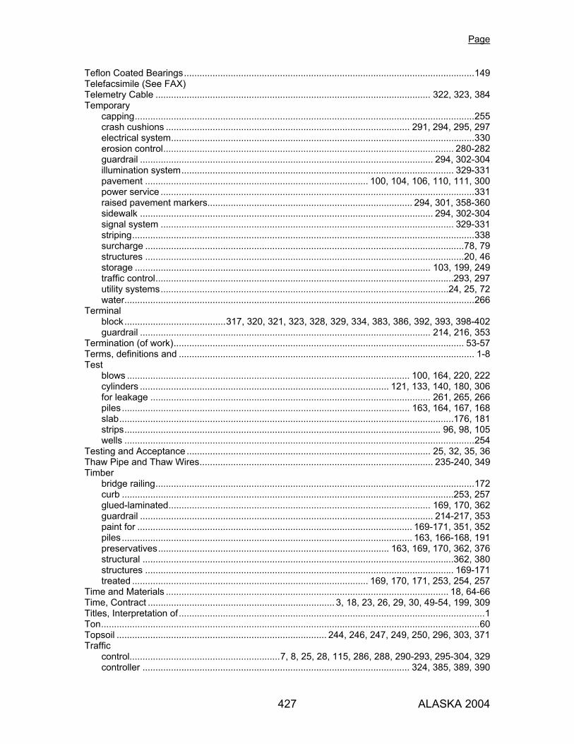
Page
427 ALASKA 2004
Teflon Coated Bearings................................................................................................................149 Telefacsimile (See FAX) Telemetry Cable .......................................................................................................... 322, 323, 384 Temporary
capping...................................................................................................................................255 crash cushions .............................................................................................. 291, 294, 295, 297 electrical system.....................................................................................................................330 erosion control................................................................................................................ 280-282 guardrail ................................................................................................................. 294, 302-304 illumination system......................................................................................................... 329-331 pavement ...................................................................................... 100, 104, 106, 110, 111, 300 power service .........................................................................................................................331 raised pavement markers............................................................................... 294, 301, 358-360 sidewalk ................................................................................................................. 294, 302-304 signal system ................................................................................................................. 329-331 striping....................................................................................................................................338 surcharge ...........................................................................................................................78, 79 structures ...........................................................................................................................20, 46 storage .................................................................................................................. 103, 199, 249 traffic control...................................................................................................................293, 297 utility systems...............................................................................................................24, 25, 72 water.......................................................................................................................................266
Terminal block.......................................317, 320, 321, 323, 328, 329, 334, 383, 386, 392, 393, 398-402 guardrail ................................................................................................................ 214, 216, 353
Termination (of work)................................................................................................................ 53-57 Terms, definitions and .................................................................................................................. 1-8 Test
blows ............................................................................................................. 100, 164, 220, 222 cylinders ................................................................................................ 121, 133, 140, 180, 306 for leakage ............................................................................................................ 261, 265, 266 piles ............................................................................................................... 163, 164, 167, 168 slab.................................................................................................................................176, 181 strips.......................................................................................................................... 96, 98, 105 wells .......................................................................................................................................254
Testing and Acceptance .............................................................................................. 25, 32, 35, 36 Thaw Pipe and Thaw Wires.......................................................................................... 235-240, 349 Timber
bridge railing...........................................................................................................................172 curb ................................................................................................................................253, 257 glued-laminated..................................................................................................... 169, 170, 362 guardrail ................................................................................................................. 214-217, 353 paint for .......................................................................................................... 169-171, 351, 352 piles ................................................................................................................ 163, 166-168, 191 preservatives......................................................................................... 163, 169, 170, 362, 376 structural ........................................................................................................................362, 380 structures ....................................................................................................................... 169-171 treated ........................................................................................... 169, 170, 171, 253, 254, 257
Time and Materials ............................................................................................................. 18, 64-66 Time, Contract ........................................................................ 3, 18, 23, 26, 29, 30, 49-54, 199, 309 Titles, Interpretation of......................................................................................................................1 Ton..................................................................................................................................................60 Topsoil ................................................................................. 244, 246, 247, 249, 250, 296, 303, 371 Traffic
control..........................................................7, 8, 25, 28, 115, 286, 288, 290-293, 295-304, 329 controller ....................................................................................................... 324, 385, 389, 390

Page
428 ALASKA 2004
control devices ........................................................................................................... 7, 290-304 control plan (TCP) .....................................................7, 8, 25, 288, 290-294, 296, 297, 299-303 control zone................................................................................................... 291, 293, 296, 298 maintenance............................................................................................................. 96, 291-304 markings........................................................................................................ 336, 338, 339, 352 price adjustment..................................................................................................... 299, 302-304 signal heads ............................................................296, 297, 320, 327-329, 378, 383, 392-396 supervisor, worksite (see superintendent) ..................................... 288, 291, 292, 296-298, 302
Traveled Way, Definition of ..............................................................................................................7 Tree Removal, Selective ..........................................................................................................69, 70 Trees, Planting...................................................................................................................... 248-252 Tremie Tubes................................................................................................................................133
U Unacceptable & Unauthorized Work, Removal of ....................................................................27, 28 Unbalanced
backfill ..............................................................................................................................83, 139 bid...................................................................................................................................5, 10, 64
Unclassified Excavation....................................................................................... 74, 76, 77, 79, 288 Underdrains ................................................................................................... 80, 212, 213, 349, 350 Underpass Lighting...................................................................................................... 329, 331, 403 Unit Price ..................................................................................................... 9, 10, 47, 56, 63, 64, 66 Utilities
Bid Considerations ...................................................................................................................24 Compensation ....................................................................................................................25, 26 Cooperation with Utility Owners...............................................................................................24 Utility Work .........................................................................................................................25, 72
Utility, Definition of ............................................................................................................................7
V Valve Boxes................................................................................................................. 263, 265, 266 Value Engineering Proposal .....................................................................................................20, 21 Vehicles ................................................................................................................................307, 308 Vibrating Concrete............................................................................................... 130, 164, 177, 223 Voids in Mineral Aggregate (VMA) ...............................................................................................100 Volatile Organic Compounds (VOCs)...........................................................................................351
W Wage Rates ..............................................................................................................................42, 47 Warning Lights..................................................................................... 215, 291, 293, 297, 298, 303 Warranties ....................................................................... 29, 34, 235, 279, 312, 325, 393, 394, 397 Wastewater Treatment Plan .........................................................................................................183 Water
conduit................................................................................................... 263, 266, 267, 349, 350 for compaction................................................................................................. 77, 79, 87, 88, 91 for concrete ........................................................................................... 119, 121, 123, 176, 355 stops.......................................................................................................................................369 system............................................................................................. 72, 256, 257, 263, 265, 266 storm .............................................................................................................. 2, 25, 49, 280-284 construction over................................................................................................................16, 43 pollution.......................................................................................................... 2, 25, 49, 280-282
Watering ....................................................................................................... 133, 250, 258, 302-304
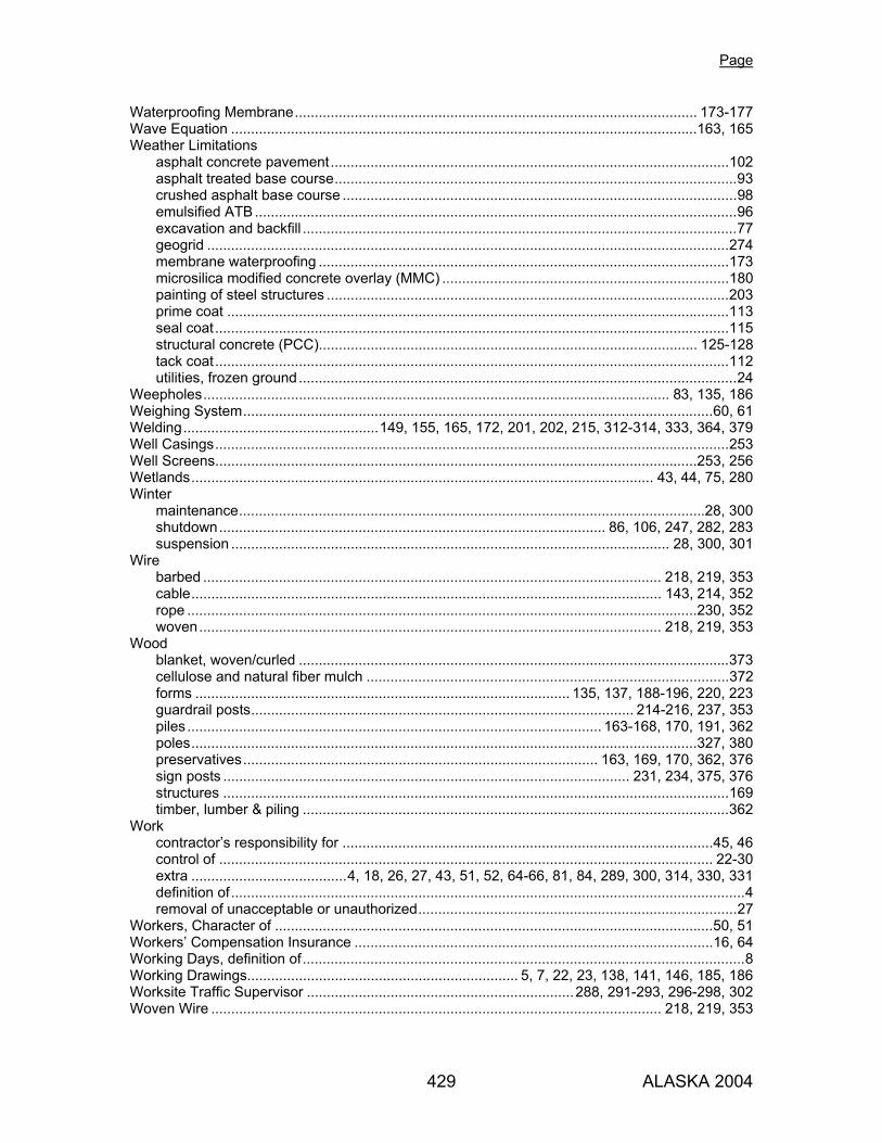
Page
429 ALASKA 2004
Waterproofing Membrane..................................................................................................... 173-177 Wave Equation .....................................................................................................................163, 165 Weather Limitations
asphalt concrete pavement....................................................................................................102 asphalt treated base course.....................................................................................................93 crushed asphalt base course ...................................................................................................98 emulsified ATB .........................................................................................................................96 excavation and backfill .............................................................................................................77 geogrid ...................................................................................................................................274 membrane waterproofing .......................................................................................................173 microsilica modified concrete overlay (MMC) ........................................................................180 painting of steel structures .....................................................................................................203 prime coat ..............................................................................................................................113 seal coat.................................................................................................................................115 structural concrete (PCC)............................................................................................... 125-128 tack coat.................................................................................................................................112 utilities, frozen ground..............................................................................................................24
Weepholes..................................................................................................................... 83, 135, 186 Weighing System......................................................................................................................60, 61 Welding.................................................149, 155, 165, 172, 201, 202, 215, 312-314, 333, 364, 379 Well Casings.................................................................................................................................253 Well Screens.........................................................................................................................253, 256 Wetlands.................................................................................................................... 43, 44, 75, 280 Winter
maintenance.....................................................................................................................28, 300 shutdown................................................................................................. 86, 106, 247, 282, 283 suspension .............................................................................................................. 28, 300, 301
Wire barbed ................................................................................................................... 218, 219, 353 cable...................................................................................................................... 143, 214, 352 rope ................................................................................................................................230, 352 woven.................................................................................................................... 218, 219, 353
Wood blanket, woven/curled ............................................................................................................373 cellulose and natural fiber mulch ...........................................................................................372 forms .............................................................................................. 135, 137, 188-196, 220, 223 guardrail posts................................................................................................ 214-216, 237, 353 piles ........................................................................................................ 163-168, 170, 191, 362 poles...............................................................................................................................327, 380 preservatives......................................................................................... 163, 169, 170, 362, 376 sign posts ...................................................................................................... 231, 234, 375, 376 structures ...............................................................................................................................169 timber, lumber & piling ...........................................................................................................362
Work contractor’s responsibility for .............................................................................................45, 46 control of ............................................................................................................................ 22-30 extra .......................................4, 18, 26, 27, 43, 51, 52, 64-66, 81, 84, 289, 300, 314, 330, 331 definition of.................................................................................................................................4 removal of unacceptable or unauthorized................................................................................27
Workers, Character of ..............................................................................................................50, 51 Workers’ Compensation Insurance ..........................................................................................16, 64 Working Days, definition of...............................................................................................................8 Working Drawings.................................................................... 5, 7, 22, 23, 138, 141, 146, 185, 186 Worksite Traffic Supervisor ...................................................................288, 291-293, 296-298, 302 Woven Wire ................................................................................................................. 218, 219, 353

Page
430 ALASKA 2004
Y Yarn ......................................................................................................................................372, 373 Yield
sign.........................................................................................................................................293 strength ................................................................................................. 148, 169, 364, 368, 378 stress..............................................................................................................................165, 191 test..................................................................................................................................255, 256
Z
Zinc
arsenate .................................................................................................................................376 chloride...................................................................................................................................376 chromate ................................................................................................................................316 coating................................................................................................................... 206, 376, 377 galvanizing (see galvanizing)....................................................................................................... powder ...................................................................................................................................351 -rich primer ............................................................................................................ 158, 160, 161
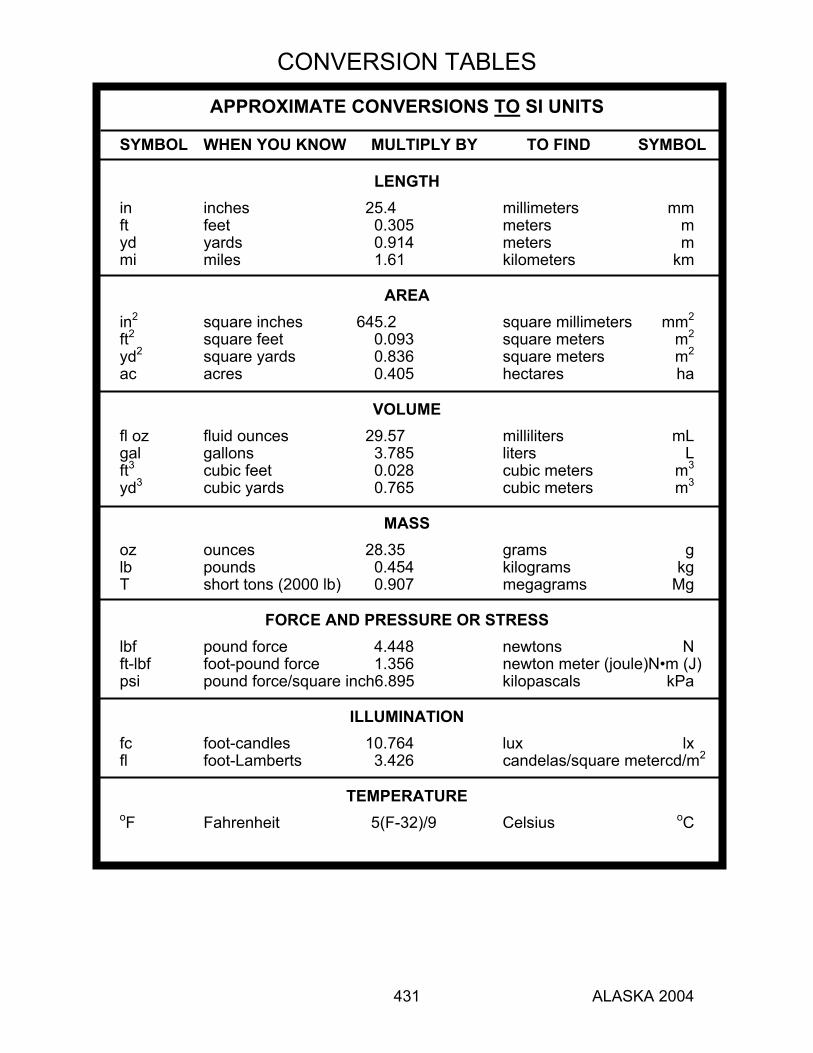
CONVERSION TABLES
431 ALASKA 2004
APPROXIMATE CONVERSIONS TO SI UNITS
SYMBOL WHEN YOU KNOW MULTIPLY BY TO FIND SYMBOL
LENGTH in inches 25.4 millimeters mm ft feet 0.305 meters m yd yards 0.914 meters m mi miles 1.61 kilometers km
AREA in2 square inches 645.2 square millimeters mm2 ft2 square feet 0.093 square meters m2 yd2 square yards 0.836 square meters m2 ac acres 0.405 hectares ha
VOLUME fl oz fluid ounces 29.57 milliliters mL gal gallons 3.785 liters L ft3 cubic feet 0.028 cubic meters m3 yd3 cubic yards 0.765 cubic meters m3
MASS oz ounces 28.35 grams g lb pounds 0.454 kilograms kg T short tons (2000 lb) 0.907 megagrams Mg
FORCE AND PRESSURE OR STRESS lbf pound force 4.448 newtons N ft-lbf foot-pound force 1.356 newton meter (joule)N•m (J) psi pound force/square inch6.895 kilopascals kPa
ILLUMINATION fc foot-candles 10.764 lux lx fl foot-Lamberts 3.426 candelas/square metercd/m2
TEMPERATURE oF Fahrenheit 5(F-32)/9 Celsius oC

CONVERSION TABLES
432 ALASKA 2004
APPROXIMATE CONVERSIONS FROM SI UNITS
SYMBOL WHEN YOU KNOW MULTIPLY BY TO FIND SYMBOL
LENGTH mm millimeters 0.039 inches in m meters 3.281 feet ft m meters 1.094 yards yd km kilometers 0.621 miles mi
AREA mm2 square millimeters 0.0016 square inches in2 m2 square meters 10.764 square feet ft2 m2 square meters 1.196 square yards yd2 ha hectares 2.471 acres ac
VOLUME mL milliliters 0.034 fluid ounces fl oz L liters 0.264 gallons gal m3 cubic meters 35.314 cubic feet ft3 m3 cubic meters 1.308 cubic yards yd3
MASS g grams 0.035 ounces oz kg kilograms 2.205 pounds lb Mg megagrams 1.102 short tons (2000 lb) T
FORCE AND PRESSURE OR STRESS N•m (J) newton meter (joule) 0.738 foot-pound force ft-lbf N newtons 0.225 pound force lbf kPa kilopascals 0.145 pound force/square inchpsi
ILLUMINATION lx lux 0.093 foot-candles fc cd/m2 candelas/square meter 0.292 foot-Lamberts fl
TEMPERATURE oC Celsius 1.8C + 32 Fahrenheit oF
32 98.6 212 oF -40 0 40 80 120 160 200 240 280 320 360 oC -40 -20 0 20 40 60 80 100 120 140 160 180 37