Embed Size (px)
Citation preview

2/4/8 ZONE CONVENTIONAL FIRE ALARM CONTROL PANEL
CHANNEL SAFETY SYSTEMS t: 0845 884 7000Petersfi eld Business Park f: 0845 884 6000Bedford RoadPetersfi eldHampshire e: [email protected] 3QA w: www.channelsafety.co.uk
AlarmSense
2/4/8 ZONE CONVENTIONAL FIRE ALARM
CONTROL PANEL

2/4/8 ZONE CONVENTIONAL FIRE ALARM CONTROL PANEL | 2
Contents
Safety ................................................................................................................................ 3
Important information regarding the safe use of this fi re alarm panel
Key Features ......................................................................................................................3
Lists the diff erent features available on the range of conventional fi re alarm panels
Fire Alarm Systems - An Overview ...................................................................................4
How fi re alarm systems operate and a general overview of their key features
User Responsibilities .........................................................................................................5
General guidelines on what the user is expected to do
Panel Layout/Accessing the Controls ...............................................................................6A summary of the controls and indicators available on this fi re alarm panel, including:Control level defi nitionHow to access the panel’s secure user functionsWhat the indicator lights mean
Fire Conditions ..................................................................................................................8How an alarm is indicated, and how to deal with itHow to silence the alarm soundersHow to manually activate the alarm sounders (i.e. to evacuate the building)How to reset a fi re alarm condition
Fault Conditions ................................................................................................................9
The diff erent types of fault that may occur, what they mean and how to deal with them
Disablements ........................................................................................................................10
How to inhibit the functionality of certain parts of the fi re alarm system
Notes on Delays ...................................................................................................................12
Important information about delays, what they mean and what you should do about them

2/4/8 ZONE CONVENTIONAL FIRE ALARM CONTROL PANEL | 3
System Set-Up Data Chart ...................................................................................................13
Details of how the system has been set-up
Fire Alarm Log Book ............................................................................................................14
A place for you to record details of events such as fi res, false alarms, call outs, etc.
Certifi cate of Installation .................................................................................................................19
Certifi cate of Commissioning ...........................................................................................................20
2/4/8 ZONE CONVENTIONAL FIRE ALARM CONTROL PANEL | 4
SAFETYThe fi re alarm panel is safe to operate provided it has been installed in compliance with the manufacturer’s instructions and used in accordance with this user manual.Do not operate the fi re alarm panel with its enclosure open. There is no need to open the enclosure except to carry out com-missioning, maintenance and remedial work. This work must only be carried out by competent service personnel who are fully conversant with the contents of the separate engineering manual for this product and have the necessary skills for maintain-ing this equipment.If the enclosure is damaged in any way, expert advice should be sought regarding its repair.Regular servicing of the fi re alarm system is highly recommended, preferably on a continuous maintenance contract and by a competent organisation. A full-itemised report of the installation should be obtained at least annually.
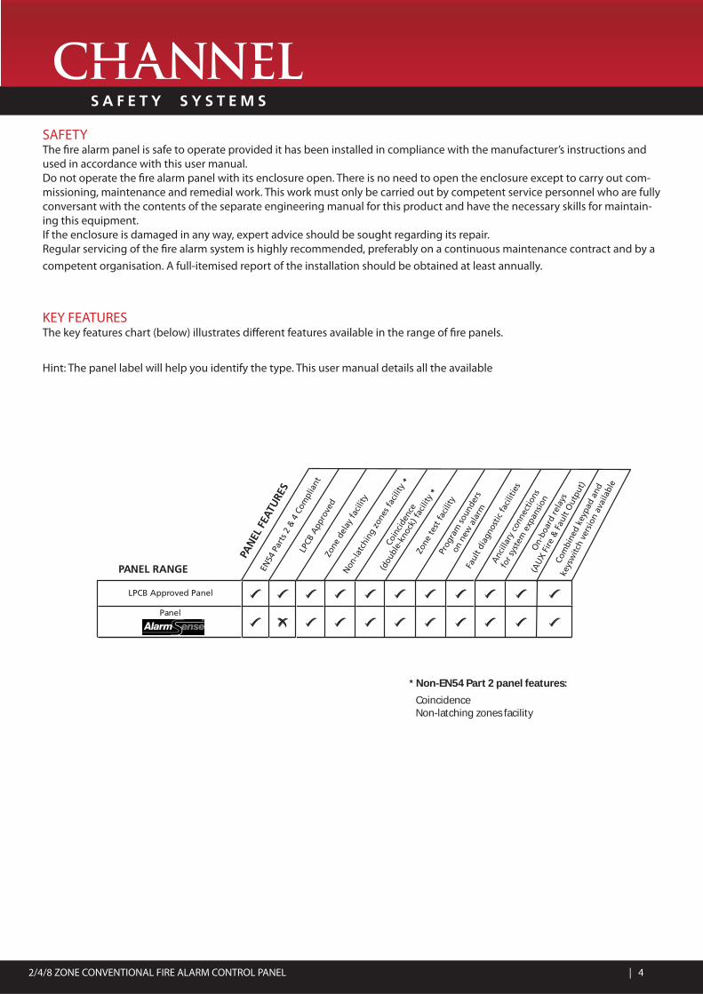
KEY FEATURESThe key features chart (below) illustrates diff erent features available in the range of fi re panels.
Hint: The panel label will help you identify the type. This user manual details all the available
Non
-latc
hing
zon
es fa
cilit
y *
Zone
del
ay fa
cilit
y
Coin
cide
nce
(dou
ble-
knoc
k) fa
cilit
y *
Zone
test
faci
lity
Faul
t dia
gnos
tic fa
cilit
ies
Anc
illar
y co
nnec
tions
for s
yste
m e
xpan
sion
On-
boar
d re
lays
(AU
X Fi
re &
Fau
lt O
utpu
t)PANEL RANGE
PAN
EL F
EATU
RES
Com
bine
d ke
ypad
and
keys
witc
h ve
rsio
n av
aila
ble
Panel
LPCB Approved Panel
Prog
ram
soun
ders
on n
ew a
larm
EN54
Par
ts 2
& 4
Com
plia
nt
LPCB
App
rove
d
* Non-EN54 Part 2 panel features:
Coincidence Non-latching zones facility

2/4/8 ZONE CONVENTIONAL FIRE ALARM CONTROL PANEL | 5
FIRE ALARM SYSTEMS – AN OVERVIEWThe primary purpose of a fi re alarm system is to provide an early warning of a fi re so that people and animals can be evacu-ated and action taken to stop the fi re as soon as possible - all according to a predetermined plan.Alarms may be raised automatically by smoke or heat detectors, or manually by a person operating a manual call point.To ensure an alarm is dealt with in an orderly manner, it is important to know where the alarm is coming from. To aid this func-tion, fi re alarm systems are usually split into zones, each covering a diff erent area of a building.When an alarm has been raised, the fi re alarm panel responds by indicating the zone in which the alarm has occurred and activating all relevant sounders, bells and other alarm outputs to provide a warning of the fi re.Additional alarm outputs available on the CFP range of fi re alarm panels (which may, or may not be used depending on the requirements of the site) are:• A Remote Output: this output is activated when the panel is in alarm and is returned to normal when the alarm sound-ers are silenced. It may be used to signal an alarm condition to other parts of the fi re alarm system. If used, its function will be declared on the System Set-Up Data Chart (page 13) of this manual. This output may be disabled if required.• An Auxiliary Output: this output is activated when the panel is in alarm and is returned to normal when the panel is reset. It may be used to signal an alarm condition to other parts of the fi re alarm system. If used, its function will be declared on the System Set-Up Data Chart (page 13) of this user manual. This output may be disabled if required.The building’s fi re management plan should always be executed when the fi re alarm panel goes into alarm.See User Responsibilities (page 5) for further details.Fault monitoringFor obvious reasons, the reliability of the fi re alarm system is paramount. To this end, the fi re alarm panel continuously moni-tors all connections between detectors, manual call points and sounders and also checks it’s own power supply and back-up batteries for faults.If a fault is detected anywhere on the system, the panel responds by illuminating one or more of the Fault light(s) located on the panel front and sounding its internal fault buzzer. The panel’s fault output is also activated, sending notifi cation of the fault (if connected) to a remote manned monitoring centre or other electronic equipment, as required.DelaysCertain zones on a fi re alarm system can be prone to conditions that lead to frequent and unavoidable false alarms, a common example being a loading bay fi lled with vehicle smoke. In such areas it may be acceptable to delay the activation of the alarm sounders and other outputs to give a responsible person time to investigate the cause of the alarm. If the cause is found to be a true fi re hazard, the delay can be overridden.In the event of a false alarm, the panel can be reset. Should the delay period expire without any user intervention, the alarm sounders will automatically sound to evacuate the premises. To ascertain if any delays have been programmed into the panel, refer to the System Set-Up Data Chart (page 13).DisablementsIn abnormal conditions, certain parts of the fi re alarm system can be temporarily turned off (disabled) to suit prevailing condi-tions. For example, if there is a risk of a false alarm occurring in a zone, say from vehicle exhaust smoke in a loading bay, it is possible to disable that zone during the risk period, then enable it again afterwards. Another example is the disablement of outputs during a routine test or temporary fault.CoincidenceThe consequence of a false alarm on some fi re alarm systems, particularly those connected to sprinkler or gas extinguishant systems, can be onerous. To help reduce the risk of a false alarm, certain zones on the system can be coupled together so that the alarm sounders and outputs only activate when there is a fi re condition on both zones. The only way to tell if and how this feature has been utilised is to refer to the System Set-up Data Chart (page 13).

2/4/8 ZONE CONVENTIONAL FIRE ALARM CONTROL PANEL | 6
USER RESPONSIBILITIESBS5839-1 is the British Standard code of practice for the design, installation, commissioning and maintenance of fi re detection and fi re alarm systems for buildings. Section 7 of the standard (UserResponsibilities) states that a named responsible person should be appointed to supervise all matters pertaining to the fi re alarm system {clause 47.2a}.Highlighted below is a summary of the main functions of the responsible person is expected to carry out with regard to BS5839-1 only. It does not highlight any other responsibilities that may be required of the user or responsible person that is listed in documentation such as the Employers Guide to Fire Safety, theFire Precautions (Workplace) regulations and/or any other legislation relevant to the premises. If in doubt, the fi re authority can advise on the fi re legislation that applies to any given building.For countries outside the UK, diff erent user responsibilities may apply.
BS5839-1 states the responsible person should:(The bracketed numbers {xx} identify the BS5839-1 clauses to which the summary refers).1 Ensure the fi re alarm panel is checked daily to confi rm there are no faults on the system {47.2b}.2 Ensure arrangements are in place for the test, maintenance and regular servicing of the system with regard to Section 6 of the standard {47.2c}.Important: Clause 44 of BS5839-1 recommends weekly and monthly tests that should be carried out by the user/responsible person - please refer to the bottom of this section for further details.3 Ensure the system log book is kept up to date by recording fi re signals, fault signals, work on the system, etc, and make sure it is available for inspection at all times {47.2d/48}.4 Ensure that all relevant occupants of the protected premises are instructed in the proper use of the system {47.2e}.5 Take steps to limit the number of false alarms on the system {47f }.6 Ensure the eff ectiveness of the system is not impaired by ensuring there is a space of at least 500mm in all directions around and below every fi re detector and that all manual call points are unobstructed and easy to see {47g}.7 Liaise with all relevant building engineers, decorators, etc., to ensure any changes to (or maintenance of ), the building’s fabric does not compromise the protection given by the fi re alarm system, create faults or false alarms {47h}.8 Ensure that any structural or occupancy changes planned for the building are done so with due and early consideration given to any changes that may be required to the fi re system {47h}.9 Ensure that a selection of spare parts are held as appropriate within the premises {47j}.
Routine weekly and monthly testing to be undertaken by the user/responsible person:To meet the requirements of Clause 44 of BS5839-1 we recommend the following tests are carried out at approximately the same time each week, during normal working hours:Note: It is essential any alarm receiving centre is contacted before and after these tests to avoid unwanted alarms and to con-fi rm the fi re signal is correctly received.• Carry out an indicator lamp test to check all Zone lights show and the beeper sounds.• Operate a manual call point or smoke/heat detector to test the fi re alarm.• Check that the alarm sounders operate.• Reset the system by pressing the Silence/Resound Sounders button and Control Panel Reset button.• Verify that no manual call points or smoke/heat detectors are obstructed in any way.• Test a diff erent zone each week using a diff erent call point or detector so all are tested in rotation.
Monthly attention: Ensure authorised service personnel verify the system’s standby power supply (or supplies) are in good working order.
Quarterly and periodic inspection, testing, servicing and maintenanceIt is the user’s responsibility to ensure that an ongoing periodic plan is in place that meets Clause 45(Inspection and Servicing) of BS5839-1. The work required to meet this Clause must be carried out by a competent person with specialist knowledge of fi re detection and alarm systems.The standard recognises this will normally be an outside specialist fi re alarm servicing organisation.
Please note: the above summaries do not replace Sections 6 and 7 of BS5839-1 but are intended to help the user gain a greater understanding of his or her responsibilities. We strongly recommend the named responsible person familiarises them-selves with the full and current standard.

2/4/8 ZONE CONVENTIONAL FIRE ALARM CONTROL PANEL | 7
PANEL LAYOUT/ACCESSING THE CONTROLSThe fi re alarm panel allows both keyswitch and keypad entry methods for entering access level two.Note: Repeater Fault and Output Delays lights are not on the CFP Economy Panel.
Two levels of control are available to user(s) of this fi re alarm panel; General User and Authorised User.
1. General User Controls (access level one)When the panel is in access level one, the indicator lights on the panel front give a comprehensive overview of the system’s current status. Any fi re and fault conditions are clearly displayed, disablements highlighted and the status of all outputs re-ported. For detailed descriptions of what each light means, see page 7.The only functions that can be performed by the user when the panel is in access level one are:• Muting the panel’s internal sounder by pressing the Silence Internal Sounder button;• Overriding any delays (CFP model dependent - see page 3) which may have been programmed into the panel by pressing the Silence/Resound Sounders button (only applicable when the panelis in alarm); or• Putting the panel into access level two (the Authorised User state) - see below.
2. Authorised User Controls (access level two)To avoid unauthorised changes to critical parts of the fi re alarm system, controls such as silencing the sounders, resetting an alarm condition and setting disablements are only accessible via a secure methodof entry which puts the panel into access level two.To put the panel into access level two using keypad entry:Enter the code 2 1 4 3 using the keypad buttons on the panel front. During the code entry sequence, the panel’s Accessed light will pulse. If an incorrect sequence of numbers is entered after four button presses the Accessed light will stop pulsing and you must enter the code again. When the correct code is entered, the Accessed light will be lit steady to indicate that the controls are operative. To exit access level two, press the Exit Access Mode button.
To put the panel into access level two using the keyswitch:Turn the key to the ‘I’ position (Note: The key cannot be removed when in this position). When the keyis in the ‘I’ position, the Accessed light will be lit steady to indicate that the controls are operative.To exit access level two, turn the key back to the ‘O’ position.Details of how to use the Authorised User controls can be found on pages 8 to 11 of this user manual.

2/4/8 ZONE CONVENTIONAL FIRE ALARM CONTROL PANEL | 8
What the indicator lights mean
The table below summarises the various indicators available on the fi re alarm panel and what they mean in their various states. The fi nal column highlights the pages(s) you should turn to for further information.
LIGHT STATUS OF LIGHT WHAT THIS MEANS FURTHER READING
(General Fire)
Flashing Red The panel has detected a fire alarm condition, orthe Silence/Resound Sounders button has beenpressed to evacuate the building
Page 8 (Fire Conditions)
Steady Red There is a silenced fire alarm condition on thesystem
Fire Zones1 to 8
Flashing Red A fire alarm condition has been detected on thezones which are flashing
Steady Red There is a silenced fire alarm condition on thezones which are lit steady
Zone Fault/Disable/Test1 to 8
Flashing Yellow(in sync. with the
General Fault light)
Faulty wiring has been detected on the zoneswhich are flashing
Page 9 (Fault Conditions)
Flashing Yellow(in sync. with the
Test light)
The zones which are flashing are in test mode
Steady Yellow The zones which are lit steady have been disabled Page 10 (Disablements)
Supply Present Steady Green The panel is supplied with power Page 4 (Overview)
Remote Output Steady Red The remote output has been activated
Test Flashing Yellow The panel is in test mode
Accessed Flashing Yellow The access code is in the process of being entered Page 6 (Accessing the Controls)
Steady Yellow The panel is in access level two
General Disablement Flashing Yellow The panel is in the disablement selection state Page 10 (Disablements)
Steady Yellow Part of the system has been manually disabledand/or one or more of the fire zones have a delayapplied to them (CFP model dependent - see page 3)
Page 10 (Disablements)Page 12 (Notes on Delays)
Fault Output Status Steady Yellow The fault output has been disabled Page 10 (Disablements)
Remote Output Status Flashing Yellow A fault has been detected on the output’s auxiliary24V supply
Page 9 (Fault Conditions)
Steady Yellow The remote output has been disabled Page 10 (Disablements)
General Fault Flashing Yellow A fault has been detected on the system Page 9 (Fault Conditions)
Power Supply Fault Flashing Yellow The panel has detected a fault with its powersupply, battery charger or back-up batteries
System Fault Flashing Yellow The panel has detected a microprocessor fault
Repeater Fault (modeldependent - see page 3)
Flashing Yellow The panel has detected a wiring/communicationfault on the repeater network
Sounder Status Flashing Yellow Faulty wiring has been detected on the panel’ssounder circuits
Steady Yellow The alarm sounders have been disabled Page 10 (Disablements)
Auxiliary Output Status Steady Yellow The panel’s auxiliary output has been disabled Page 10 (Disablements)
Output Delays (CFPmodel dependent - seepage 3)
Steady Yellow Delays have been programmed into the panel Page 12 (Notes on Delays)
Flashing Yellow A delay is running
FIRE
Testing the indicator lights
To test the panel’s indicator lights are working correctly, press the Lamp Test button when the panel is in the accessed state. The panel’s internal beeper also sounds when pressing this button to show it is working correctly.

2/4/8 ZONE CONVENTIONAL FIRE ALARM CONTROL PANEL | 9
FIRE CONDITIONS
When the fi re alarm panel receives an alarm trigger from a detector or manual call point located in a zone that is not already in a fi re state, it will:• Flash the general fi re and appropriate Fire Zone light(s) on the panel front.• Activate its internal sounder.• Start the alarm sounders and outputs including, if enabled, the remote and auxiliary outputs (provided there are no delays applicable to the zone which is in alarm - model dependent, see page 3).
At this point the building’s fi re management plan should be executed!Important Note: Zones which have been disabled cannot be triggered into an alarm condition (see page 10 for further infor-mation on disablements).
Silencing the alarm sounders• The alarm sounders may be silenced by putting the panel into access level two and pressing theSilence/Resound Sounders button.The alarm sounders and the panel’s internal sounder will stop sounding and the light(s) for the zone(s) in alarm and the Gen-eral Fire light will be lit steady. The remote output will turn off , but the auxiliary output will stay on.New zone in alarmShould a new zone be triggered into alarm whilst the alarm sounders are silenced, the panel will:• Automatically reactivate the alarm sounders (if programmed to do so).• Flash the General Fire light and appropriate Fire Zone light(s) for any new zone(s) in alarm.• Keep the light(s) for the previous zone(s) in fi re lit steady.
Manually activating the alarm sounders (i.e. to evacuate the building• Momentarily pressing the Silence/Resound Sounders button when the panel is in access level two (see page 6) will cause the alarm sounders to sound. Note: The panel’s remote and auxiliary fi re outputs will not be triggered when the building is manu-ally evacuated in this way.Pressing the Silence/Resound Sounders button again will silence the alarm sounders.Note: If the sounders have been disabled, pressing the Silence/Resound Sounders button will have no eff ect.
Resetting the panel• After the cause of the alarm has been investigated and cleared and the alarm sounders have been silenced, the panel can be reset by pressing the Control Panel Reset button.The panel will give a double beep to indicate the reset process has started and, after a few seconds, theFire Zone and General Fire lights will go out to indicate the process is complete. If there are still alarm triggers on any zone the panel will go back into alarm as before.
Fire Zone LightsGeneral Fire Light
27 35 4618Fire Zones
Fire

2/4/8 ZONE CONVENTIONAL FIRE ALARM CONTROL PANEL | 10
FAULT CONDITIONS
When a fault occurs on a critical part of the fi re alarm system, the panel responds by activating its internal sounder and il-luminating the General Fault light and any other Fault light(s) relating to the fault. The panel’s fault output will also activate (provided it hasn’t been disabled). The type of faults typically indicated at the fi re alarm panel are described below:
In the event of a fault condition:
• Mute the panel’s internal sounder by pressing the Silence Internal Sounder button (the panel does not have to be in access level two to do this).• Record the fault(s) in the Fire Alarm Log Book (page 14) and take appropriate action to correct it/them.See User Responsibilities (page 5).When a fault has been rectifi ed the indicator light for that fault is automatically turned off . If all faults are cleared, the General Fault light will go out, and the panel’s internal sounder will be silent (if not already muted). If the fi re alarm panel is reset any existing fault(s) will reappear as before and the silencing process will have to be repeated.

2/4/8 ZONE CONVENTIONAL FIRE ALARM CONTROL PANEL | 11
DISABLEMENTS
Certain fi re alarm panel functions can be temporarily disabled (i.e. switched off ) to suit certain conditions. For example, if there is a risk of a false alarm in a zone, e.g. from vehicle exhaust smoke in a loading bay, it is possible for the user to disable that zone during the risk period and enable it again afterwards. Another example is the disablement of outputs during a rou-tine test or temporary fault.The following is a list of options that may be disabled by a level two user at the fi re alarm panel and the eff ect their disable-ment will have on how the system works:
To disable or enable any of the above options:1. Put the fi re alarm panel into access level two (see Authorised User Controls - page 6).2. Start the selection process by pressing and holding the Next Option button for 3 seconds.The General Disablement light will fl ash and the Fault light relating to the fi rst option in the above table will fl ash to show it is selected.If the light fl ashes at a slower rate than the General Disablement light, the option is enabled.If the light fl ashes at the same rate as the General Disablement light, the option is disabled.3. If necessary, press the Enable/Disable button to toggle the selected option between disabled and enabled.4. To confi rm your choice, press the Next Option button.This will move the selection process on to the next available option in the above table and the Fault light relating to this new option will fl ash to show it is selected. The previous option’s Fault light will now be lit steady to confi rm it is disabled, or switched off to confi rm it is enabled.5. Repeat steps 3 & 4 for every available option until the selection process is complete.The disablement/enablement process is complete when all available options have been selected in turn and theNext Option button is pressed for the last time. At this point all disabled options will be lit steady and all enabled options will have their lights switched off .Note: The selection process can be exited at any time by pressing the Exit Access Mode button, or by turning the keyswitch to ‘O’ position. The only changes that will be saved will be those made prior to the last press of the Next Option button.

2/4/8 ZONE CONVENTIONAL FIRE ALARM CONTROL PANEL | 12
Notes about disablements
(a) The option of disabling or enabling zones 3 & 4 and zones 5, 6, 7 & 8 is only available if these zones are fi tted. If they are not fi tted, the selection process will skip to the next available option.(b) The option of disabling or enabling output delays is only available if delays have been programmed into the fi re alarm panel by the installation engineer. If a delay has been programmed into the panel the Output Delays light will be lit when the panel is in the normal (i.e. non-accessed) state.Important: Please refer to the ‘Notes on Delays’ (page 12) before proceeding to make any changes to the way the delays func-tion operates.
Diagram to show the disablement/enablement selection sequence

2/4/8 ZONE CONVENTIONAL FIRE ALARM CONTROL PANEL | 13
NOTES ON DELAYS
What is a delay?
A delay can be programmed into the fi re alarm panel to postpone the activation of the alarm sounders and other outputs for a predetermined length of time. The delay period gives a responsible person time to investigate the cause of an alarm, usually in areas which are prone to false alarm (such as vehicle exhaust smoke in a loading bay) before the building is evacuated. If the cause of the alarm is found to be a true fi re hazard, the delay can be overridden and the alarm sounders activated immedi-ately.Alternatively, in the case of a false alarm, the panel can be reset.
Delay options
One, some or all of the zones on the fi re alarm panel can have a delay applied to them to suit the requirements of the site. The same delay period applies to all delayed zones and is adjustable to a maximum of 10 minutes. The programming of delays must only be carried out by competent service personnel who are advised to record all relevant delay data on the System Set-Up Data Chart (page 13) of this user manual. Delays should only be used with the prior knowledge and consent of all relevant authorities, i.e. fi re offi cer, building control, etc.
Delay indication
If delays have been programmed into the panel the Output Delays light and the General Disablement light will be lit steady. This means the immediate turning on of the alarm sounders and other outputs on one or more zones has been disabled. The only way to ascertain which zones have been programmed with a delay is to refer to the System Set-Up Data Chart (page 13)
What happens when there is a fi re alarm condition on a delayed zone?
Should an alarm occur on a delayed zone, the panel will:• Flash its General Fire and appropriate Fire Zone light(s)• Sound its internal sounder• Start the delay countdown sequence• Indicate a delay is running by fl ashing its Output Delays light
How to override a delay in the event of a true fi re alarm condition
• If, on investigation, the cause of the alarm on the delayed zone is found to be a true fi re hazard, pressing the Silence/Resound Sounders button at any time will override the delay and activate the alarm sounders and outputs with immediate eff ect.
How to reset the system in the event of a false alarm
• If, on investigation, the cause of the alarm is found to be false, put the panel into access level two (see Authorised User Con-trols - page 6) and press the Control Panel Reset button.
How to turn the delays function on or off
Any delays that have been programmed into the panel can be turned on or off by putting the panel into access level two and following the disablement/enablement selection process as described on pages 10 and 11.Selecting the Output Delays option and then pressing the Enable/Disable button so that the OutputDelays light fl ashes in synchronisation with the General Disablement light shows that the delays are on.Pressing the Enable/Disable button again will make the Output Delays light fl ash slower than the GeneralDisablement light, showing that the delays are off .Having chosen the desired setting, pressing the Next Option button will exit the disablement/enablement selection process. The Output Delays light will now be lit steady with theGeneral Disablement light, showing that delays are on, or the Output Delays light will be off , showing that delays are off .

2/4/8 ZONE CONVENTIONAL FIRE ALARM CONTROL PANEL | 14
SYSTEM SET-UP DATA CHART
Important: This page should be carefully completed by an authorised engineer prior to system hand-over.
THE INFORMATION ABOVE WAS COMPLETED BY (name) _______________________________OF (company) _________________________________________ ON (date) __________________(*) NOTES ON COINCIDENCE: The following applies to all pairs of zones which are set up for coincidence. There must be alarms on both zones (i.e. zone 1 and zone 2) before the alarm sounders and outputs turn on. If only one of the zones (i.e. zone 1) goes into alarm, the panel indicates the alarm by illuminating the relevant light on the panel front and sounding its internal sounder, thus prompting the user to investi-gate. If found to be false, the alarm can be reset or, if found to be a true fi re condition, the sounders can be manually activated by pressing theSilence/Resound Sounders button - as detailed on page 8.

2/4/8 ZONE CONVENTIONAL FIRE ALARM CONTROL PANEL | 15
FIRE ALARM LOG BOOK
It is recommended that this log book be maintained by a responsible person, who should ensure that every entry is properly recorded. In the UK, this is necessary to satisfy the recommendations of BS5839-1, compliance with which may be a require-ment of legislation. If your premises are certifi cated under the Fire Precautions Act 1971, failure to keep a suitable log book may be a breach of the requirements of the certifi cate, which is a criminal off ence. In order to satisfy the requirements of BS5839-1 the following must be recorded:
• The name of the responsible person;• Brief details of the maintenance arrangements;• Dates and times of all tests, including fi re drills;• Dates and times of all fi res to which the system responds;• Dates and times of all false alarms;• Causes, circumstances surrounding, and category of false alarms (if known);• The identity of any manual call point or fi re detector that triggers any of the above fi re alarm signals (if known);• Dates, times and type of all faults and defects.• Dates and times of all maintenance (e.g service visit or non-routine attention).

2/4/8 ZONE CONVENTIONAL FIRE ALARM CONTROL PANEL | 16
Details of tests (including fi re drills), actual fi re alarms, disablements or enablements and faults should be recorded here. False alarms and maintenance work should also be recorded on page 18

2/4/8 ZONE CONVENTIONAL FIRE ALARM CONTROL PANEL | 17

2/4/8 ZONE CONVENTIONAL FIRE ALARM CONTROL PANEL | 18

2/4/8 ZONE CONVENTIONAL FIRE ALARM CONTROL PANEL | 19
False alarms
Maintenance work

2/4/8 ZONE CONVENTIONAL FIRE ALARM CONTROL PANEL | 20
BS5839-1 recommends that certifi cates be issued for all aspects of the fi re alarm system including design, installation, commissioning, acceptance, verifi cation (optional) and maintenance. Therefore, before this user manual is handed over, the following installation certifi cate and commissioning certifi cate (overleaf ) should be completed as appropriate by the relevant installation/commissioning engineer(s). Please ensure that the System Set-Up Data Chart (page 13) and the relevant parts of the Fire Alarm Log Book (page 14) are also completed as appropriate. For countries outside the UK, diff erent certifi cation requirements may apply.

2/4/8 ZONE CONVENTIONAL FIRE ALARM CONTROL PANEL | 21
BS5839-1 recommends that certifi cates be issued for all aspects of the fi re alarm system including design, installation, commissioning, acceptance, verifi cation (optional) and maintenance. Therefore, before this user manual is handed over, the following commissioning certifi cate and the installation certifi cate (overleaf ) should be completed as appropriate by the relevant installation/commissioning engineer(s). Please ensure that the System Set-Up Data Chart (page 13) and the relevant parts of the Fire Alarm Log Book (page 14) are also completed as appropriate. For countries outside the UK, diff erent certifi cation requirements may apply.

2/4/8 ZONE CONVENTIONAL FIRE ALARM CONTROL PANEL
CHANNEL SAFETY SYSTEMS t: 0845 884 7000Petersfi eld Business Park f: 0845 884 6000Bedford RoadPetersfi eldHampshire e: [email protected] 3QA w: www.channelsafety.co.uk


![MULTI CHANNEL AV RECEIVER STR-DN1070MULTI CHANNEL AV RECEIVER STR-DN1070 Partes y controles Receptor Panel delantero (sección superior) [1] Panel delantero (sección inferior) [2]](https://img.dokumen.tips/doc/110x75/5e5274aef6440a00df157f31/multi-channel-av-receiver-str-dn1070-multi-channel-av-receiver-str-dn1070-partes.jpg)