Embed Size (px)
Citation preview

AKO-52067 AKO-52068
Alarma para cámara frigorífica con salida para 1 foco
Cold room store alarm with output for 1 lamp
E GB 5206H701 Ed.03
Instrucciones / Instructions
1.- Introducción
2.- Versiones y referencias
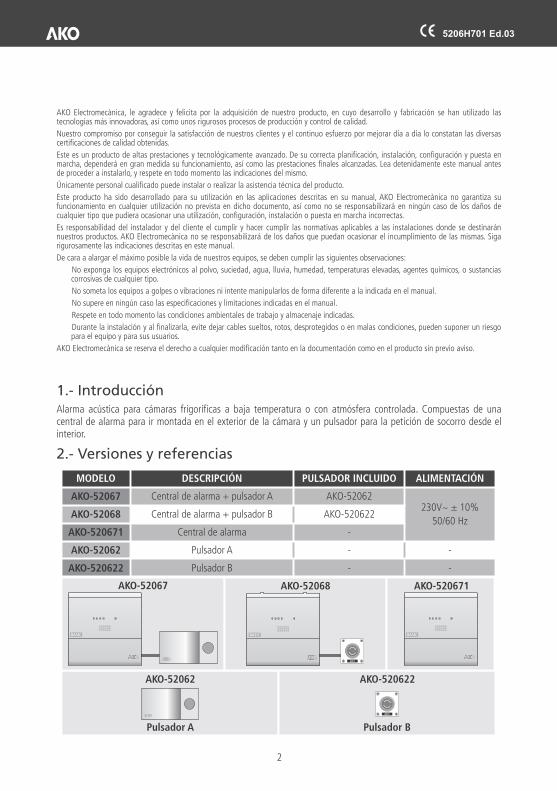
Alarma acústica para cámaras frigoríficas a baja temperatura o con atmósfera controlada. Compuestas de una central de alarma para ir montada en el exterior de la cámara y un pulsador para la petición de socorro desde el interior.
MODELO DESCRIPCIÓN PULSADOR INCLUIDO ALIMENTACIÓN
AKO-52067 Central de alarma + pulsador A AKO-52062230V~ ± 10%
50/60 HzAKO-52068 Central de alarma + pulsador B AKO-520622
AKO-520671 Central de alarma -
AKO-52062 Pulsador A - -
AKO-520622 Pulsador B - -
AKO-52062
Pulsador A Pulsador B
AKO-520622
AKO-52068AKO-52067
BASIC BASIC
AKO-520671
BASIC
AKO Electromecànica, le agradece y felicita por la adquisición de nuestro producto, en cuyo desarrollo y fabricación se han utilizado las tecnologías más innovadoras, así como unos rigurosos procesos de producción y control de calidad.
Nuestro compromiso por conseguir la satisfacción de nuestros clientes y el continuo esfuerzo por mejorar día a día lo constatan las diversas certificaciones de calidad obtenidas.
Este es un producto de altas prestaciones y tecnológicamente avanzado. De su correcta planificación, instalación, configuración y puesta en marcha, dependerá en gran medida su funcionamiento, así como las prestaciones finales alcanzadas. Lea detenidamente este manual antes de proceder a instalarlo, y respete en todo momento las indicaciones del mismo.
Únicamente personal cualificado puede instalar o realizar la asistencia técnica del producto.
Este producto ha sido desarrollado para su utilización en las aplicaciones descritas en su manual, AKO Electromecànica no garantiza su funcionamiento en cualquier utilización no prevista en dicho documento, así como no se responsabilizará en ningún caso de los daños de cualquier tipo que pudiera ocasionar una utilización, configuración, instalación o puesta en marcha incorrectas.
Es responsabilidad del instalador y del cliente el cumplir y hacer cumplir las normativas aplicables a las instalaciones donde se destinarán nuestros productos. AKO Electromecànica no se responsabilizará de los daños que puedan ocasionar el incumplimiento de las mismas. Siga rigurosamente las indicaciones descritas en este manual.
De cara a alargar el máximo posible la vida de nuestros equipos, se deben cumplir las siguientes observaciones:
No exponga los equipos electrónicos al polvo, suciedad, agua, lluvia, humedad, temperaturas elevadas, agentes químicos, o sustancias corrosivas de cualquier tipo.
No someta los equipos a golpes o vibraciones ni intente manipularlos de forma diferente a la indicada en el manual.
No supere en ningún caso las especificaciones y limitaciones indicadas en el manual.
Respete en todo momento las condiciones ambientales de trabajo y almacenaje indicadas.
Durante la instalación y al finalizarla, evite dejar cables sueltos, rotos, desprotegidos o en malas condiciones, pueden suponer un riesgo para el equipo y para sus usuarios.
AKO Electromecànica se reserva el derecho a cualquier modificación tanto en la documentación como en el producto sin previo aviso.
2
5206H701 Ed.03

5206H701 Ed.03
3.- InstalaciónLa alarma debe ser instalada en un sitio protegido de las vibraciones, del agua y de los gases corrosivos, donde la temperatura ambiente no supere el valor reflejado en los datos técnicos y en algún lugar donde se garantice la presencia de al menos una persona durante el tiempo de trabajo en la cámara.
Para que las alarmas tengan un grado de protección IP65, se deben utilizar los prensaestopas adecuados.
Montaje de la central
- Retirar la tapa T del equipo (Fig.1)- Abrir el equipo y separar el frontal de la caja (Fig.2)- Realizar los taladros para los prensaestopas necesarios para entrada de los cables guiándose por los centros
pretroquelados en los laterales de la caja.- Realizar los 3 taladros en la pared siguiendo los agujeros de fijación 1,2,3. (Fig.3).- Fijar los prensaestopas en el equipo.- Insertar y apretar los 3 tornillos+taco a través de la caja, en los 3 taladros de la pared.- Insertar los cables en los prensaestopas.- Montar el frontal en la caja (Fig.2).- Insertar y apretar los tornillos D, F (Fig.1)- Conectar los cables según el esquema de conexionado, cerrar la tapa T, insertar y apretar los tornillos A, C (Fig.1)
FIG. 2
FIG. 1
222,1 mm
140 mm
222,
1 m
m
140
mm
FIG. 3
Españ
ol
3
BASICBASIC

5206H701 Ed.03
Montaje del pulsador
El pulsador debe instalarse en el interior de la cámara, en un lugar visible y a una altura no superior a 125 cm desde el suelo.
AKO-52062
- Retirar la tapa del pulsador (Fig.4).- Realizar el taladro para el prensaestopas necesario para entrada de los cables, guiándose por los centros
pretroquelados en la parte inferior de la base.- Realizar los 3 taladros en la pared siguiendo los taladros de fijación (Fig.5).- Fijar el prensaestopa en la base.- Insertar y apretar los 3 tornillos+taco a través de la base, en los 3 taladros de la pared.- Insertar los cables en el prensaestopa y conectarlos según el esquema de conexionado.- Insertar la tapa y presionar ligeramente hasta escuchar “click”.
AKO-520622
Fijelo a la pared mediante los orificios destinados a tal fin (A), conectelo al equipo siguiendo el esquema de conexión y cierre la tapa mediante los tornillos incluidos (B).
Se incluye prensaestopas para cables de entre 6 y 12 mm Ø
Detalle taladrosfijación
Presionar ligeramente
94 60
Max. Ø 3,7FIG. 4
FIG. 5
Taladros de fijación adecuadospara caja de empotrar universal 171
125,535
41,5
B
B
A
A
Instalación recomendada
El cable debe salir del pulsador hacia abajo dibujando una curva de 180 º (según muestra la imagen) para evitar que pueda llegar agua a la entrada de cables.
180º180º
4
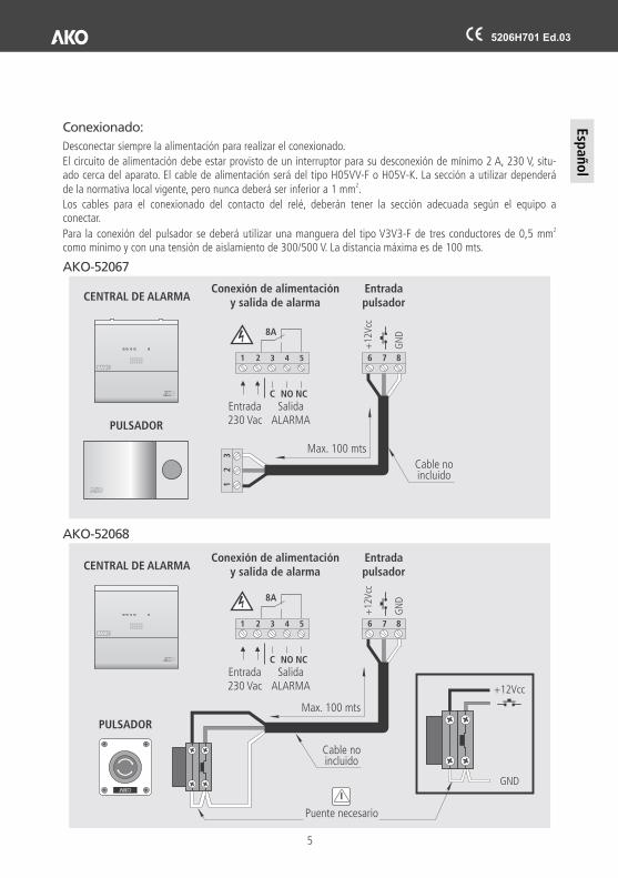
Conexionado:
Desconectar siempre la alimentación para realizar el conexionado.
El circuito de alimentación debe estar provisto de un interruptor para su desconexión de mínimo 2 A, 230 V, situ-ado cerca del aparato. El cable de alimentación será del tipo H05VV-F o H05V-K. La sección a utilizar dependerá
2de la normativa local vigente, pero nunca deberá ser inferior a 1 mm .
Los cables para el conexionado del contacto del relé, deberán tener la sección adecuada según el equipo a conectar.
2Para la conexión del pulsador se deberá utilizar una manguera del tipo V3V3-F de tres conductores de 0,5 mm como mínimo y con una tensión de aislamiento de 300/500 V. La distancia máxima es de 100 mts.
AKO-52067
6
6
1
7
7
2
8
8
3
CENTRAL DE ALARMA
AKO-52068
CENTRAL DE ALARMA
PULSADOR
PULSADOR
Conexión de alimentacióny salida de alarma
Conexión de alimentacióny salida de alarma
Entrada230 Vac
Entrada230 Vac
SalidaALARMA
SalidaALARMA
Entradapulsador
Entradapulsador
Puente necesario
Cable no incluido
Cable no incluido
Max. 100 mts
Max. 100 mts
+12
Vcc
+12
Vcc
GN
DG
ND
+12Vcc
GND
1
1
2
2
3
3
C
C
4
4
NO
NO
8A
8A
5
5
NC
NC
Españ
ol
5
BASIC
BASIC
5206H701 Ed.03

BASIC
4.- Descripción del equipo
ALARMA VISUAL
ALARMA ACÚSTICA
5.- Funcionamiento
6.- Datos técnicos
En reposo, el indicador luminoso del pulsador estará permanentemente encendido.
Para activar la alarma, presionamos el pulsador, la alarma acústica y visual se pone en funcionamiento.
Para desactivar la alarma, girar el pulsador en el sentido de las agujas del reloj hasta liberarlo, la alarma se detendrá.
La salida de alarma permite activar equipos externos de alerta (alarmas a distancia, sirenas auxiliares, etc.).
Alimentación...............................................................................................................230 V ~ ± 10%, 50/60 Hz
Potencia máxima absorbida ........................................................................................................................10 VA
Relé auxiliar ......................................................................................................................230 Vac, 8A, cos j =1
Temperatura ambiente de trabajo de la central de alarma..................................................................0 ºC a 50 ºC
Temperatura ambiente de almacenaje de la central de alarma........................................................-30 ºC a 70 ºC
Temperatura ambiente de trabajo del pulsador A (AKO-52062).....................................................-50 ºC a 50 ºC
Temperatura ambiente de almacenaje del pulsador A (AKO-52062) ..............................................-50 ºC a 70 ºC
Temperatura ambiente de trabajo del pulsador B (AKO-520622)...................................................-20 ºC a 70 ºC
Temperatura ambiente de almacenaje del pulsador B (AKO-520622) ............................................-20 ºC a 70 ºC
Grado de protección de la fuente de alimentación........................................................................................IP 65
Grado de protección del pulsador A (AKO-52062).......................................................................................IP 65
Grado de protección del pulsador B (AKO-520622).....................................................................................IP 65
Categoría de instalación .............................................................................................................II s/ EN 61010-1
Grado de polución......................................................................................................................II s/ EN 61010-1
Distancia máxima del cable de pulsador.....................................................................................................100 m
Aislamiento doble entre alimentación, circuito secundario y salida relé.
Alarma visual .................................................................................................LEDs amarillos de alta luminosidad
Alarma acústica ............................................................................................................2 x buzzer piezoeléctricos
Nivel acústico a 1 m ...................................................................................................................................90 dB
PULSADOR DE ALARMA B
PULSADOR DE ALARMA A
CENTRAL DE ALARMAAKO-520671
AKO-52062
AKO-520622
COMBINACIÓN AAKO-52067
COMBINACIÓN BAKO-52068
6
5206H701 Ed.03
1.- Introduction
2.- Versions and references
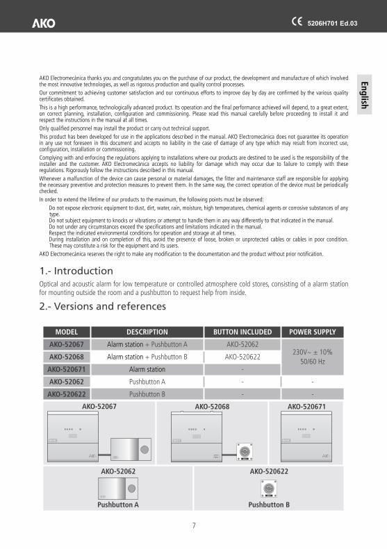
Optical and acoustic alarm for low temperature or controlled atmosphere cold stores, consisting of a alarm station for mounting outside the room and a pushbutton to request help from inside.
MODEL DESCRIPTION BUTTON INCLUDED POWER SUPPLY
AKO-52067 Alarm station + Pushbutton A AKO-52062230V~ ± 10%
50/60 HzAKO-52068 Alarm station + Pushbutton B AKO-520622
AKO-520671 Alarm station -
AKO-52062 Pushbutton A - -
AKO-520622 Pushbutton B - -
AKO-52062 AKO-520622
AKO-52068AKO-52067
BASIC BASIC
AKO-520671
BASIC
AKO Electromecànica thanks you and congratulates you on the purchase of our product, the development and manufacture of which involved the most innovative technologies, as well as rigorous production and quality control processes.
Our commitment to achieving customer satisfaction and our continuous efforts to improve day by day are confirmed by the various quality certificates obtained.
This is a high performance, technologically advanced product. Its operation and the final performance achieved will depend, to a great extent, on correct planning, installation, configuration and commissioning. Please read this manual carefully before proceeding to install it and respect the instructions in the manual at all times.
Only qualified personnel may install the product or carry out technical support.
This product has been developed for use in the applications described in the manual. AKO Electromecànica does not guarantee its operation in any use not foreseen in this document and accepts no liability in the case of damage of any type which may result from incorrect use, configuration, installation or commissioning.
Complying with and enforcing the regulations applying to installations where our products are destined to be used is the responsibility of the installer and the customer. AKO Electromecànica accepts no liability for damage which may occur due to failure to comply with these regulations. Rigorously follow the instructions described in this manual.
Whenever a malfunction of the device can cause personal or material damages, the fitter and maintenance staff are responsible for applying the necessary preventive and protection measures to prevent them. In the same way, the correct operation of the device must be periodically checked.
In order to extend the lifetime of our products to the maximum, the following points must be observed:
Do not expose electronic equipment to dust, dirt, water, rain, moisture, high temperatures, chemical agents or corrosive substances of any type.Do not subject equipment to knocks or vibrations or attempt to handle them in any way differently to that indicated in the manual.Do not under any circumstances exceed the specifications and limitations indicated in the manual.Respect the indicated environmental conditions for operation and storage at all times.During installation and on completion of this, avoid the presence of loose, broken or unprotected cables or cables in poor condition. These may constitute a risk for the equipment and its users.
AKO Electromecànica reserves the right to make any modification to the documentation and the product without prior notification.
Eng
lish
7
Pushbutton A Pushbutton B
5206H701 Ed.03
5206H701 Ed.03
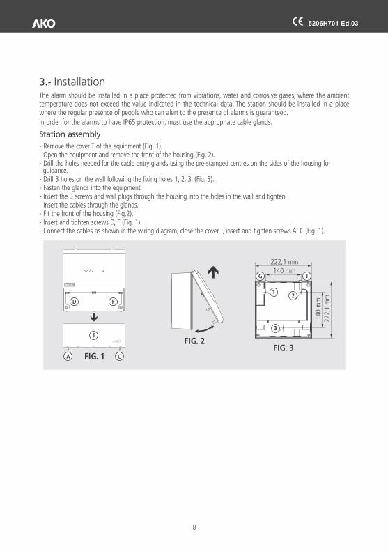
3.- InstallationThe alarm should be installed in a place protected from vibrations, water and corrosive gases, where the ambient temperature does not exceed the value indicated in the technical data. The station should be installed in a place where the regular presence of people who can alert to the presence of alarms is guaranteed.
In order for the alarms to have IP65 protection, must use the appropriate cable glands.
- Remove the cover T of the equipment (Fig. 1).- Open the equipment and remove the front of the housing (Fig. 2).- Drill the holes needed for the cable entry glands using the pre-stamped centres on the sides of the housing for
guidance.- Drill 3 holes on the wall following the fixing holes 1, 2, 3. (Fig. 3).- Fasten the glands into the equipment.- Insert the 3 screws and wall plugs through the housing into the holes in the wall and tighten.- Insert the cables through the glands.- Fit the front of the housing (Fig.2).- Insert and tighten screws D, F (Fig. 1).- Connect the cables as shown in the wiring diagram, close the cover T, insert and tighten screws A, C (Fig. 1).
Station assembly
8
FIG. 2
FIG. 1
222,1 mm
140 mm
222,
1 m
m
140
mm
FIG. 3
BASICBASIC

5206H701 Ed.03
Pushbutton assembly
The pushbutton should be installed inside the coldroom, in a visible place and no higher than 125 cm from the floor.
AKO-52062
-Remove the pushbutton's cover (Fig. 4).-Drill the hole for the included gland needed for the cable entry following the pre-stamped centres on the bottom of the base.
-Drill 3 holes on the wall following the fixing holes. (Fig. 5).-Fasten the gland onto the base.-Insert the 3 screws+plugs through the base, into the 3 holes on the wall and tighten.-Insert the cables into the gland and connect them according to the wiring diagram.-Insert the cover and gently press it until you hear a “click”.
AKO-520622
Fix to the wall using the holes for this purpose (A), connect it to the alarm station by following the wiring diagram and close the lid with screws included.
Cable gland is included for cables between 6 and 12 mm Ø.
Fixing hole detailPress gently
94 60
Max. Ø 3,7FIG. 4
FIG. 5
Fixing holes suitable for universal built-in housing 171
125,535
41,5
B
B
A
A
Eng
lish
Recomended installation
The cable must make a 180º bend after exiting from the bottom of the pushbutton (as seen in the image) to prevent water from reaching the wires.
180º180º
9
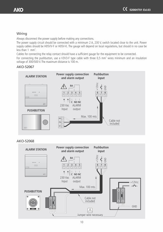
Wiring
AKO-52067
Always disconnect the power supply before making any connections.
The power supply circuit should be connected with a minimum 2 A, 230 V, switch located close to the unit. Power supply cables should be H05VV-F or H05V-K. The gauge will depend on local regulations, but should in no case be
2less than 1 mm .
Cables for connecting the relay contact should have a sufficient gauge for the equipment to be connected.2For connecting the pushbutton, use a V3V3-F type cable with three 0,5 mm wires minimum and an insulation
voltage of 300/500 V. The maximum distance is 100 m.
6
6
1
7
7
2
8
8
3
ALARM STATION
AKO-52068
ALARM STATION
PUSHBUTTON
PUSHBUTTON
Power supply connectionand alarm output
Power supply connectionand alarm output
230 VacInput
230 VacInput
ALARMoutput
ALARMoutput
Pushbuttoninput
Pushbuttoninput
Jumper wire necessary
Cable notincluded
Cable notincluded
Max. 100 mts
Max. 100 mts
+12
Vcc
+12
Vcc
GN
DG
ND
+12Vcc
GND
1
1
2
2
3
3
C
C
4
4
NO
NO
8A
8A
5
5
NC
NC
10
BASIC
BASIC
5206H701 Ed.03
BASIC
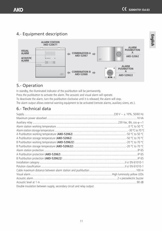
4.- Equipment description
VISUALALARM
ACOUSTIC ALARM
5.- Operation
6.- Technical data
In standby, the illuminated indicator of the pushbutton will be permanently.
Press the pushbutton to activate the alarm. The acoustic and visual alarm will operate.
To deactivate the alarm, turn the pushbutton clockwise until it is released; the alarm will stop.
The alarm output allows external warning equipment to be activated (remote alarms, auxiliary sirens, etc.).
.........................................................................................................................230 V ~ ± 10%, 50/60 Hz
.........................................................................................................................10 VA
...................................................................................................................230 Vac, 8A, cos j =1
.................................................................................................0 ºC to 50 ºC
...................................................................................................-30 ºC to 70 ºCA Pushbutton (AKO-52062) .......................................................................-50 ºC to 50 ºC
A Pushbutton (AKO-52062) ........................................................................-50 ºC to 70 ºC
B Pushbutton (AKO-520622) .....................................................................-20 ºC to 70 ºC
B Pushbutton (AKO-520622) ......................................................................-20 ºC to 70 ºC
Alarm station protection ..............................................................................................................................IP 65
A Pushbutton protection (AKO-52062) .......................................................................................................IP 65
B Pushbutton protection (AKO-520622) .....................................................................................................IP 65
...................................................................................................................II s/ EN 61010-1
.................................................................................................................II s/ EN 61010-1
C
Supply
Maximum power absorbed
Auxiliary relay
Alarm station working temperature
Alarm station storage temperatureworking temperature
storage temperature
working temperature
storage temperature
Installation category
Polution classification
able maximum distance between alarm station and pushbutton...............................................................100 m
Visual alarm..............................................................................................................High luminosity yellow LEDs
Acoustic alarm .................................................................................................................2 x piezoelectric buzzer
Acoustic level at 1 m ..................................................................................................................................90 dB
Double insulation between supply, secondary circuit and relay output.
ALARM PUSHBUTTON
A
ALARM PUSHBUTTON
A
ALARM STATIONAKO-520671
AKO-52062
AKO-520622
COMBINATION AAKO-52067
COMBINATION BAKO-52068
Eng
lish
11
5206H701 Ed.03

355206701 R
EV.0
2 2
014
Nos reservamos el derecho de suministrar materiales que pudieran diferir levemente de los descritos en nuestras Hojas Técnicas. Información actualizada en nuestra web.We reserve the right to supply materials that might vary slightly to those described in our Technical Sheets. Updated information is available on our website.
AKO ELECTROMECÁNICA , S.A.L.
Avda. Roquetes, 30-3808812 • Sant Pere de Ribes.Barcelona • Spain.
Tel.: +34 902 333 145Fax: +34 938 934 054www.ako.com