Embed Size (px)
Citation preview
Tyco Safety Products 47 Gilby Road Mt Waverley, Vic, 3149 AUSTRALIA Telephone: 61 3 9538 7204 Facsimile: 61 3 9538 7255 Website: www.tycosafetyproducts-anz.com
Safety Products
Alarm Signalling Equipment General Overview
Peter Parsons 2003-09-08

Tyco Alarm Signalling Equipment General Overview
Table of Contents 1. General Description .....................................................................................................................1 2. Functions......................................................................................................................................1 3. Monitoring Fire Alarm Systems ..................................................................................................2
3.1. Voltage-Free Relay Contacts ...............................................................................................2 3.2. Serial Data Interface.............................................................................................................3
4. Reporting Events..........................................................................................................................3 5. Indicators......................................................................................................................................4
5.1. ASE Status Indicators ..........................................................................................................4 5.2. ASE Input indicators............................................................................................................4 5.3. Fire Alarm System Status indicators....................................................................................5 5.4. Indicator Operation ..............................................................................................................5
6. Telecommunications Protocol......................................................................................................5 7. Testing..........................................................................................................................................5 8. Keys .............................................................................................................................................6
8.1. Test Key ...............................................................................................................................6 8.2. Isolate Key ...........................................................................................................................6 8.3. RSSI Key .............................................................................................................................6
9. Networks Supported.....................................................................................................................6 9.1. Radio ....................................................................................................................................6 9.2. Terrestrial .............................................................................................................................7
10. Signal Loss...............................................................................................................................7 11. Re-try Strategies.......................................................................................................................8 12. Radio Network Failure Recovery ............................................................................................8 13. Event History ...........................................................................................................................8 14. Control Program.......................................................................................................................8 15. Power Supply ...........................................................................................................................9 16. Enclosure Options ....................................................................................................................9
16.1. Standard Enclosure ..........................................................................................................9 16.2. 19" Rack Mounting ........................................................................................................10 16.3. With Power Supply ........................................................................................................10
17. Approvals ...............................................................................................................................11 18. Electromagnetic Compatibility ..............................................................................................11 19. Installation and Commissioning ............................................................................................11 20. Other Applications .................................................................................................................11 21. Specifications .........................................................................................................................12
2003-09-08
Tyco Alarm Signalling Equipment General Overview
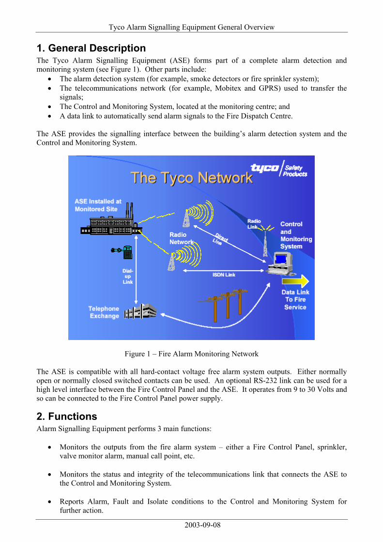
1. General Description The Tyco Alarm Signalling Equipment (ASE) forms part of a complete alarm detection and monitoring system (see Figure 1). Other parts include:
• The alarm detection system (for example, smoke detectors or fire sprinkler system); • The telecommunications network (for example, Mobitex and GPRS) used to transfer the
signals; • The Control and Monitoring System, located at the monitoring centre; and • A data link to automatically send alarm signals to the Fire Dispatch Centre.
The ASE provides the signalling interface between the building’s alarm detection system and the Control and Monitoring System.
Figure 1 – Fire Alarm Monitoring Network The ASE is compatible with all hard-contact voltage free alarm system outputs. Either normally open or normally closed switched contacts can be used. An optional RS-232 link can be used for a high level interface between the Fire Control Panel and the ASE. It operates from 9 to 30 Volts and so can be connected to the Fire Control Panel power supply.
2. Functions Alarm Signalling Equipment performs 3 main functions:
• Monitors the outputs from the fire alarm system – either a Fire Control Panel, sprinkler, valve monitor alarm, manual call point, etc.
• Monitors the status and integrity of the telecommunications link that connects the ASE to
the Control and Monitoring System.
• Reports Alarm, Fault and Isolate conditions to the Control and Monitoring System for further action.
2003-09-08

Tyco Alarm Signalling Equipment General Overview
3. Monitoring Fire Alarm Systems
3.1. Voltage-Free Relay Contacts The ASE monitors up to six different fire alarm systems using the relay contact inputs (see Figure 2). It is compatible with any make or model of Fire Control Panel that have relay outputs. It can also be used for fire sprinkler systems, sprinkler valve tamper switches, gas discharge systems and mechanical ventilation systems.
Figure 2 – Six fire alarm systems can be connected to the ASE A resistor network (see Figure 3) interfaces between the ASE and the Fire Control Panel and allows four separate conditions to be monitored over a single pair of wires. Common Alarm, Fault, Isolate (disable) and Normal conditions can be monitored from the Fire Control Panel. The relay interface is available immediately and can operate with either normally-open contacts or normally-closed contacts.
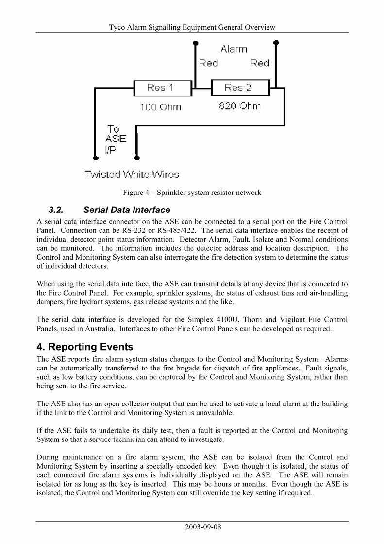
Figure 3 – Fire Control Panel resistor network For simple systems, like a sprinkler, the ASE may only be required to monitor for the Alarm condition. A separate resistor network is available for a single Alarm output from a system (see Figure 4).
2003-09-08
Tyco Alarm Signalling Equipment General Overview
Figure 4 – Sprinkler system resistor network
3.2. Serial Data Interface A serial data interface connector on the ASE can be connected to a serial port on the Fire Control Panel. Connection can be RS-232 or RS-485/422. The serial data interface enables the receipt of individual detector point status information. Detector Alarm, Fault, Isolate and Normal conditions can be monitored. The information includes the detector address and location description. The Control and Monitoring System can also interrogate the fire detection system to determine the status of individual detectors. When using the serial data interface, the ASE can transmit details of any device that is connected to the Fire Control Panel. For example, sprinkler systems, the status of exhaust fans and air-handling dampers, fire hydrant systems, gas release systems and the like. The serial data interface is developed for the Simplex 4100U, Thorn and Vigilant Fire Control Panels, used in Australia. Interfaces to other Fire Control Panels can be developed as required.
4. Reporting Events The ASE reports fire alarm system status changes to the Control and Monitoring System. Alarms can be automatically transferred to the fire brigade for dispatch of fire appliances. Fault signals, such as low battery conditions, can be captured by the Control and Monitoring System, rather than being sent to the fire service. The ASE also has an open collector output that can be used to activate a local alarm at the building if the link to the Control and Monitoring System is unavailable. If the ASE fails to undertake its daily test, then a fault is reported at the Control and Monitoring System so that a service technician can attend to investigate. During maintenance on a fire alarm system, the ASE can be isolated from the Control and Monitoring System by inserting a specially encoded key. Even though it is isolated, the status of each connected fire alarm systems is individually displayed on the ASE. The ASE will remain isolated for as long as the key is inserted. This may be hours or months. Even though the ASE is isolated, the Control and Monitoring System can still override the key setting if required.
2003-09-08

Tyco Alarm Signalling Equipment General Overview
The ASE has a back-up telephone link in the event that the primary link is unavailable. The ordinary telephone line can be utilised in the event that the radio link is unavailable. The use of these diverse paths (radio and land based) provides a significant improvement over any monitoring system that uses a single link (or even two links using the same technology).
5. Indicators The ASE indicators are grouped into:
• ASE Status indicators • ASE Input indicators • Fire Alarm System Status indicators
Figure 5 – ASE indicators
5.1. ASE Status Indicators The ASE Status indicators are located in the top left-hand area and the bottom right hand area of the ASE. These provide the overall status of the ASE. The top left hand indicators show:
• Comms– whether the radio link, the telephone link, both, or neither is available. When communications are normal, the Comms indicator is on steady. If communications is lost to either the radio network or the backup network, then the Comms indicator flashes using a coded sequence to enable a service technician to determine where the fault has occurred.
• Power– that power is available to the ASE. • Fault– whether the ASE is operating correctly or not.
The bottom right hand indicators show:
• Wiring fault – a fault in the wiring between the ASE and the fire alarm system. • ASE Isolate – whether the whole ASE is isolated or not. • ASE Test Mode – when the ASE is in Test Mode.
5.2. ASE Input indicators The ASE Inputs each have individual indicators. Up to six separate fire alarm systems may be monitored by a single ASE.
2003-09-08
Tyco Alarm Signalling Equipment General Overview
There is area on the ASE label to describe the Alarm Type, and perhaps its location.
5.3. Fire Alarm System Status indicators The status of individual fire alarm systems connected to the ASE is displayed in the top right-hand corner. Alarm conditions, Faults conditions reported by the fire alarm system and whether the fire alarm is isolated from the Control and Monitoring System are all indicated.
5.4. Indicator Operation The ASE indicators are clear and easy to interpret. When a condition initially occurs, say an alarm activation, the ASE input indicator will come on and the red Alarm indicator will flash. This shows that the ASE has received the alarm, but is yet to transfer the alarm to the Control and Monitoring System. When the condition has been received by Control and Monitoring System, and confirmed back to the ASE, the indicator will change from flashing to steady. If more than one conditions is present at any time, the relevant ASE Inputs will cycle from one to the other, displaying the status of the relevant Input.
6. Telecommunications Protocol The monitoring application uses an event-initiated protocol. There is no polling of the equipment. This means that when an event occurs, the ASE immediately transmits the event to the monitoring centre for processing. It does not have to wait for a cyclic poll. This provides both rapid and efficient notification of events. Whilst this is fast and efficient, failure of the telecommunications link may go un-noticed for some time. A backup telephone line is required to reduce the time that buildings are not being monitored. The telephone is constantly monitored, tested once per day and used to report any failures of the radio link. The ASE can be configured to operate with just the radio or just the backup link.
7. Testing Testing of the ASE occurs automatically at a preset time. The backup line is used for the daily test. The test time is set when the ASE is installed, but this can be changed at any time from the Control and Monitoring System. Manual testing of the connected alarm detection systems is undertaken using a special encoded key. The ASE displays the status of the test so that engineers receive visual feedback of successful tests to the Control and Monitoring System.
2003-09-08

Tyco Alarm Signalling Equipment General Overview
8. Keys Three keys are available for use with the ASE (see Figure 6). All keys are encoded with a unique identifier to enable tracking of who uses the key and when.
Figure 6 – Keys
The keys can be configured to permit or prevent operation of designated ASE units and provide building owners with greater control over who has authority to perform certain functions with the ASE.
8.1. Test Key A Test Key is used to simulate an Alarm, Fault or Isolate condition to Control and Monitoring System. When the Test Key is inserted into the ASE, the ASE Test Mode indicator comes on and simulated conditions can be checked for successful transmission to the Monitoring Centre.
8.2. Isolate Key An Isolate Key is used to isolate all the ASE Inputs from transmitting messages to the Control and Monitoring System. When the Isolate Key is inserted into the ASE, the ASE Isolate indicator comes on. The ASE will remain isolated for as long as the Isolate Key is plugged in.
8.3. RSSI Key For the Mobitex network, the RSSI key causes the ASE to display the signal strength of the two most powerful radio base stations, using the columns of LED indicators as a bar graph. This key is used during the commissioning of the ASE unit.
9. Networks Supported
9.1. Radio The following radio networks are supported by the ASE.
9.1.1. Mobitex The Mobitex network is fully supported by the ASE. Mobitex provides a fast, reliable and robust network for mission critical applications such as fire alarm monitoring. Alarm messages are
2003-09-08
Tyco Alarm Signalling Equipment General Overview
received in approximately 2 seconds. No connection establishment procedures are required once the ASE is on-line and the ASE continually monitors for contact with the radio network. Additional features available with Mobitex include the ability to measure the radio signal strength from the radio base stations. This enables the installer to quickly locate the best position for the radio antenna to ensure strong and reliable contact with the network. Tyco owns and operates the Mobitex network in Australia and has more than five years of experience with operating a fire alarm monitoring network.
9.1.2. GPRS The GPRS network is fully supported by the ASE. GPRS provides a cheap solution. It is best suited to non-critical applications where life safety is not a priority. It may be more vulnerable to congestion due to a large number of consumer users.
9.1.3. PLANET The PLANET network GRFM100 radio is currently being interfaced to the ASE. It is expected that the engineering integration will be completed within one month.
9.2. Terrestrial The following terrestrial networks are supported by the ASE.
9.2.1. PSTN The Public Switched Telephone Network (PSTN) using a normal dial-up telephone line is fully supported. Either a PABX extension or a direct outside telephone line can be used. The line is continuously monitored for voltage from the telephone exchange equipment and any loss of the line is reported to the Control and Monitoring System via the radio link. Where there is no radio coverage, the ASE can be configured to operate with two PSTN connections or one PSTN connection and one leased line connection.
9.2.2. ADSL ADSL connection is not supported, however an Ethernet connection, using an RJ-45 connector, is under development. The Ethernet connection point can be used to connect to an ADSL or ISDN modem, or another connection point to the internet. The Ethernet connection point will provide the level of flexibility needed to ensure the Tyco ASE meets future changes in telecommunications technologies.
9.2.3. Leased Line A direct leased line option is fully support.
10. Signal Loss In the event of the loss of one of the transmission paths, the ASE signals the failure to the Control and Monitoring System via the other link. If both paths fail, the ASE can be configured to initiate a warning signal at the building. Even if power fails, the ASE will still attempt to send events to the Control and Monitoring System until the ASE receives an acknowledgement. In addition, as the ASE undertakes a daily automatic test, if the test is missed, then the Control and Monitoring System can alert the monitoring centre staff.
2003-09-08
Tyco Alarm Signalling Equipment General Overview
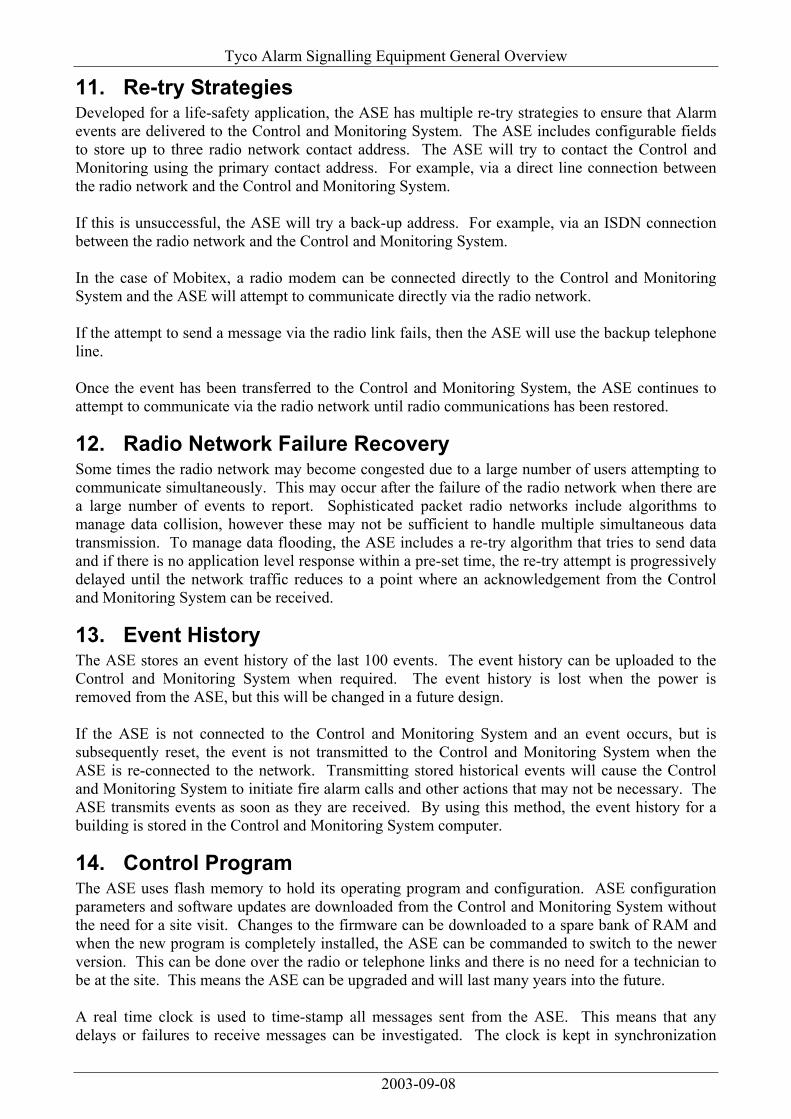
11. Re-try Strategies Developed for a life-safety application, the ASE has multiple re-try strategies to ensure that Alarm events are delivered to the Control and Monitoring System. The ASE includes configurable fields to store up to three radio network contact address. The ASE will try to contact the Control and Monitoring using the primary contact address. For example, via a direct line connection between the radio network and the Control and Monitoring System. If this is unsuccessful, the ASE will try a back-up address. For example, via an ISDN connection between the radio network and the Control and Monitoring System. In the case of Mobitex, a radio modem can be connected directly to the Control and Monitoring System and the ASE will attempt to communicate directly via the radio network. If the attempt to send a message via the radio link fails, then the ASE will use the backup telephone line. Once the event has been transferred to the Control and Monitoring System, the ASE continues to attempt to communicate via the radio network until radio communications has been restored.
12. Radio Network Failure Recovery Some times the radio network may become congested due to a large number of users attempting to communicate simultaneously. This may occur after the failure of the radio network when there are a large number of events to report. Sophisticated packet radio networks include algorithms to manage data collision, however these may not be sufficient to handle multiple simultaneous data transmission. To manage data flooding, the ASE includes a re-try algorithm that tries to send data and if there is no application level response within a pre-set time, the re-try attempt is progressively delayed until the network traffic reduces to a point where an acknowledgement from the Control and Monitoring System can be received.
13. Event History The ASE stores an event history of the last 100 events. The event history can be uploaded to the Control and Monitoring System when required. The event history is lost when the power is removed from the ASE, but this will be changed in a future design. If the ASE is not connected to the Control and Monitoring System and an event occurs, but is subsequently reset, the event is not transmitted to the Control and Monitoring System when the ASE is re-connected to the network. Transmitting stored historical events will cause the Control and Monitoring System to initiate fire alarm calls and other actions that may not be necessary. The ASE transmits events as soon as they are received. By using this method, the event history for a building is stored in the Control and Monitoring System computer.
14. Control Program The ASE uses flash memory to hold its operating program and configuration. ASE configuration parameters and software updates are downloaded from the Control and Monitoring System without the need for a site visit. Changes to the firmware can be downloaded to a spare bank of RAM and when the new program is completely installed, the ASE can be commanded to switch to the newer version. This can be done over the radio or telephone links and there is no need for a technician to be at the site. This means the ASE can be upgraded and will last many years into the future. A real time clock is used to time-stamp all messages sent from the ASE. This means that any delays or failures to receive messages can be investigated. The clock is kept in synchronization
2003-09-08

Tyco Alarm Signalling Equipment General Overview
with the master clock in the Control and Monitoring System and is used to ensure that pre-programmed testing occurs within the required time. A watchdog timer monitors the correct operation of the control program. If the program execution fails, the watchdog will re-start the program.
15. Power Supply The ASE is normally powered from a DC supply (9.5 to 29 V). The power supply normally comes from the Fire Control Panel, so it is not necessary to have a separate battery. A separate internal battery is not required by Australian Standards. If an internal battery is required, the cost will be higher. If a separate external battery is required, the cost will be higher.
16. Enclosure Options The ASE has three enclosure options.
16.1. Standard Enclosure The standard enclosure is a rugged die-cast metal enclosure rated to IP51. It is resistant to ingress of water and dust and provides good mechanical protection in harsh environments and is designed to be surface mounted adjacent to, or within the alarm detection system enclosure at the remote monitored site (see Figure 7).
Figure 7 – Standard ASE in metal enclosure The compact size makes the ASE suitable for mounting within existing fire alarm systems where space is difficult to obtain. Cable glands are fitted to simplify installation. A label is provided to write identifying details of the monitored alarm detection systems, and Test Instructions are printed on the front of the unit to guide personnel through the simple test procedure.
2003-09-08

Tyco Alarm Signalling Equipment General Overview
16.2. 19" Rack Mounting The 19" rack mount enclosure is ideal where the ASE is required to be mounted as part of an existing equipment rack. The 3U panel is hinged at one end to enable the panel to be swung open to access the ASE and its terminations (See Figure 8).
Figure 8 – 19" rack mount
16.3. With Power Supply Where DC power is not available, the ASE can be mounted within a power supply cabinet (see Figure 9). The power supply includes a battery charger and complies with Australian Standards for electrical safety. A number of different size batteries can be fitted to the power supply, providing a backup time of several hours to several days.
Figure 9 – ASE with power supply unit
Both the 19" rack mount plate and the power supply have mounting points for the antenna.
2003-09-08
Tyco Alarm Signalling Equipment General Overview
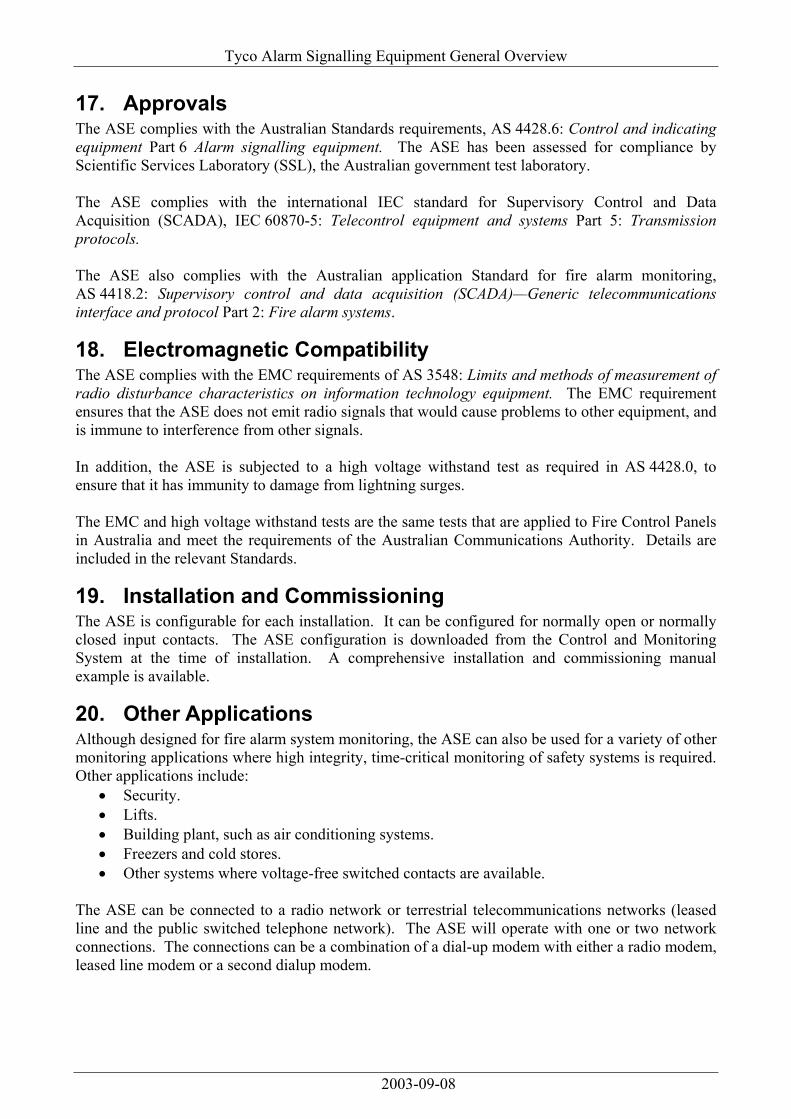
17. Approvals The ASE complies with the Australian Standards requirements, AS 4428.6: Control and indicating equipment Part 6 Alarm signalling equipment. The ASE has been assessed for compliance by Scientific Services Laboratory (SSL), the Australian government test laboratory. The ASE complies with the international IEC standard for Supervisory Control and Data Acquisition (SCADA), IEC 60870-5: Telecontrol equipment and systems Part 5: Transmission protocols. The ASE also complies with the Australian application Standard for fire alarm monitoring, AS 4418.2: Supervisory control and data acquisition (SCADA)—Generic telecommunications interface and protocol Part 2: Fire alarm systems.
18. Electromagnetic Compatibility The ASE complies with the EMC requirements of AS 3548: Limits and methods of measurement of radio disturbance characteristics on information technology equipment. The EMC requirement ensures that the ASE does not emit radio signals that would cause problems to other equipment, and is immune to interference from other signals. In addition, the ASE is subjected to a high voltage withstand test as required in AS 4428.0, to ensure that it has immunity to damage from lightning surges. The EMC and high voltage withstand tests are the same tests that are applied to Fire Control Panels in Australia and meet the requirements of the Australian Communications Authority. Details are included in the relevant Standards.
19. Installation and Commissioning The ASE is configurable for each installation. It can be configured for normally open or normally closed input contacts. The ASE configuration is downloaded from the Control and Monitoring System at the time of installation. A comprehensive installation and commissioning manual example is available.
20. Other Applications Although designed for fire alarm system monitoring, the ASE can also be used for a variety of other monitoring applications where high integrity, time-critical monitoring of safety systems is required. Other applications include:
• Security. • Lifts. • Building plant, such as air conditioning systems. • Freezers and cold stores. • Other systems where voltage-free switched contacts are available.
The ASE can be connected to a radio network or terrestrial telecommunications networks (leased line and the public switched telephone network). The ASE will operate with one or two network connections. The connections can be a combination of a dial-up modem with either a radio modem, leased line modem or a second dialup modem.
2003-09-08
Tyco Alarm Signalling Equipment General Overview
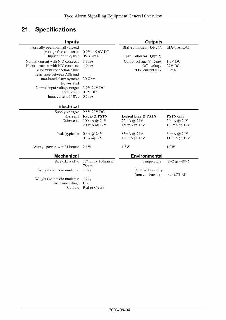
21. Specifications
Inputs Outputs Normally open/normally closed
(voltage free contacts): 0.0V to 9.0V DC Dial up modem (Qty: 1): EIA/TIA RJ45
Input current @ 0V: 0V 4.2mA Open Collector (Qty: 2): Normal current with N/O contacts: 1.8mA Output voltage @ 15mA: 1.0V DC Normal current with N/C contacts: 4.0mA “Off” voltage: 29V DC
Maximum connection cable resistance between ASE and
monitored alarm system: 30 Ohm
“On” current sink: 30mA
Power Fail Normal input voltage range: 3.0V-29V DC
Fault level: 0.9V DC Input current @ 0V: 0.5mA
Electrical
Supply voltage: 9.5V-29V DC Current Radio & PSTN Leased Line & PSTN PSTN only
Quiescent: 100mA @ 24V 75mA @ 24V 50mA @ 24V 200mA @ 12V 150mA @ 12V 100mA @ 12V
Peak (typical): 0.4A @ 24V 85mA @ 24V 60mA @ 24V 0.7A @ 12V 160mA @ 12V 110mA @ 12V
Average power over 24 hours: 2.5W 1.8W 1.0W
Mechanical Environmental Size (HxWxD): 174mm x 100mm x
78mm Temperature: -5°C to +45°C
Weight (no radio modem): 1.0kg Relative Humidity (non condensing): 0 to 95% RH
Weight (with radio modem): 1.2kg Enclosure rating: IP51
Colour: Red or Cream
2003-09-08