Embed Size (px)
Citation preview

INGECON SUN STORAGE 1PLAY
ABH2010IMC03_F.docx 09/10/2019
1/61
INGECON SUN STORAGE 1PLAY
Alarm Interpretation and Troubleshooting Guide

INGECON SUN STORAGE 1PLAY
ABH2010IMC03_F.docx 09/10/2019
2/61
Table of contents
1 INTRODUCTION .......................................................................................................................................... 5
1.1 Revision History ...................................................................................................................................... 5
2 EVENTS ....................................................................................................................................................... 6
2.1 DEFINITIONS ......................................................................................................................................... 6
2.1.1 Alarms ............................................................................................................................................ 6
2.1.2 Unit Operating Codes (Code1 and Code2) .................................................................................... 7
2.1.3 Stop Event ..................................................................................................................................... 7
2.1.4 Warning .......................................................................................................................................... 7
2.1.5 LEDS MEANING ............................................................................................................................ 7
3 Origin and description of the events ............................................................................................................. 8
4 INCIDENT WORKFLOW ............................................................................................................................ 16
4.1 Alarm 0x00000001, Code 2 0x0080: Stop Event 1 Vbat Low .............................................................. 17
4.2 Alarm 0x00000001 Code 2 0x0100: Stop Event 1 Vbat High .............................................................. 18
4.3 Alarm 0x00000002 and Alarm 0x0000004 ........................................................................................... 19
4.4 Alarm 0x00000008: Stop Event 7 DC/AC Converter´s Overcurrent or Fault ....................................... 20
4.5 Alarm 0x00000010: DC/DC Converter´s Overcurrent (Stop Event 9) or Fault (Stop Event 8) ............ 21
4.6 Alarm 0x00000020: Insulation failure ................................................................................................... 22
4.7 Alarm 0x00000040: Stop Event 22. Synchronization alarm in 3 Phase Systems. ............................... 23
4.8 Alarm 0x00000080: Temperature. Stop Events 16 and 17. ................................................................. 24
4.9 Alarm 0x00000100: DC Bus Overvoltage. Stop Event 6. ..................................................................... 25
4.10 Alarm 0x00000200: Configuration Change. Stop Event 25. ............................................................ 26
4.11 Alarm 0x00000400: Stop Inverter Command. .................................................................................. 26
4.12 Alarm 0x00000800: HW Failure. ...................................................................................................... 27
4.13 Alarm 0x00001000: Repetitive DC/DC or DC/AC Error. Stop Event 23. ......................................... 28
4.14 Alarm 0x00002000: Overload in AC Grid Port. Stop Events 26. ..................................................... 28
4.15 Alarm 0x00004000: High Battery Temperature. Stop Events 17. .................................................... 29
4.16 Alarm 0x00010000: Overload in AC Loads Port. Stop Events 11 and 12. ...................................... 30
4.17 Alarm 0x00020000: Short circuit in AC Loads. Stop Event 13. ....................................................... 30
4.18 Alarm 0x00040000: PT100 Temperature sensor. ............................................................................ 31
4.19 Alarm 0x00080000 and 0x00400000: Communication Error with the BMS. .................................... 32
4.20 Alarm 0x00100000: Wrong Inverter Serial Number. ........................................................................ 33
4.21 Alarm 0x00200000: High Instantaneous Grid Voltage. Stop Event 5. ............................................. 33
4.22 Alarm 0x00800000: Alarm in the BMS. Stop Event 30. Code 2 0x2000 .......................................... 34
4.23 Alarm 0x01000000: Overcurrent in PV array input. Stop Event 11. ................................................ 35
4.24 Alarm 0x02000000, Code 3 0x0040: Stop Event 1 Battery SOC Low (SOCdescx). ....................... 35
4.25 Warning: Code 3 0x0004: DC/DC converter cannot elevate. .......................................................... 36

INGECON SUN STORAGE 1PLAY
ABH2010IMC03_F.docx 09/10/2019
3/61
4.26 Warning: Code 3 0x0008: Synchronization with the grid not successful. ........................................ 36
4.27 Warning: Code 3 0x0020: Bus CAN Communication Error. ............................................................ 37
5 TRAINING INSTRUCTIONS ...................................................................................................................... 38
5.1 CHECKING MEASURES ..................................................................................................................... 38
5.1.1 Inverter measures Vbat measurement is correct? ....................................................................... 38
5.1.2 All battery cells are functional? .................................................................................................... 39
5.1.3 Check the communication between de battery and the inverter.................................................. 39
5.1.4 Check that the display is working correctly. ................................................................................. 39
5.1.5 Check the battery temperature sensor (PT100). ......................................................................... 40
5.1.6 Check internal CAN Bus Wire. ..................................................................................................... 40
5.2 MEASUREMENTS ON INVERTER ...................................................................................................... 41
5.2.1 Measure the Battery Voltage with a voltimeter on the Inverter´s terminals. ................................ 41
5.2.2 Check the Battery´s Insulation. .................................................................................................... 41
5.2.3 Measure PV panel´s open circuit Voltage.................................................................................... 41
5.2.4 Check the PV Array´s Insulation. ................................................................................................. 42
5.2.5 Measure the Grid/Genset Voltage and Frequency on the Inverter´s terminals. .......................... 42
5.2.6 Check the Load Port´s Insulation. ................................................................................................ 42
5.2.7 Check the Grid/Genset Port´s Insulation ..................................................................................... 43
5.2.8 Measure the Voltage between Loads and Grid/Genset Ports ..................................................... 43
5.2.9 Measure the Impedance between Loads and Grid/Genset Ports ............................................... 43
5.2.10 Measure the DC/AC Inductor´s Current. ...................................................................................... 45
5.3 BASIC CONFIGURATION CHANGES ................................................................................................. 46
5.3.1 Set COUNTRY/REGULATION .................................................................................................... 46
5.3.2 Set TYPE OF GRID ..................................................................................................................... 46
5.3.3 Set NOMINAL VAC AND FAC ..................................................................................................... 47
5.3.4 Set GENERATOR VAC/FAC SETTINGS .................................................................................... 47
5.3.5 Set GRID VAC/FAC SETTINGS .................................................................................................. 48
5.3.6 Set BATTERY CAPACITY VALUES (C20h and C5h) ................................................................. 49
5.3.7 Set Inverter´s configuration for the AC Phase of the Inverter ...................................................... 49
5.3.8 Check and Change BATTERY´S MAXIMUM DISCHARGING CURRENT SETTING ................ 50
5.3.9 Set TYPE OF BATTERY .............................................................................................................. 50
5.3.10 Check the RS485 Communication Timeout. ................................................................................ 51
5.3.11 Check Battery Type Config .......................................................................................................... 51
5.4 BASIC INSTRUCTIONS INGECON SUN MANAGER (ISM) ............................................................... 51
5.4.1 Access ISM as Service Level ...................................................................................................... 51
5.4.2 Sending MODBUS COMANDS via ISM ...................................................................................... 52
5.4.3 Downloading datalogger through ISM ......................................................................................... 53

INGECON SUN STORAGE 1PLAY
ABH2010IMC03_F.docx 09/10/2019
4/61
5.4.4 Identify STOP REASON through ISM .......................................................................................... 54
5.4.5 Read/Set the INVERTER SERIAL NUMBER through ISM ......................................................... 55
5.4.6 Read/Set CONFIGURATION PARAMETERS trough ISM .......................................................... 56
5.4.7 UPGRADE FW through ISM ........................................................................................................ 57
5.5 OTHER TESTS ..................................................................................................................................... 58
5.5.1 Fan´s Test .................................................................................................................................... 58
5.5.2 Start/Stop Inverter ........................................................................................................................ 58
6 ANEX .......................................................................................................................................................... 59
6.1 Safety requirements ............................................................................................................................. 59
6.2 Required elements ............................................................................................................................... 61
6.2.1 Instrumentation ............................................................................................................................ 61
6.2.2 Documentation ............................................................................................................................. 61
6.2.3 PC Software ................................................................................................................................. 61
6.2.4 Accesories ................................................................................................................................... 61

INGECON SUN STORAGE 1PLAY
ABH2010IMC03_F.docx 09/10/2019
5/61
1 INTRODUCTION
The purpose of this document is to guide through the different ways of resolution for the events that can
appear in inverters of the family of Ingecon Sun Storage 1 Play.
The document is divided in three big blocks:
- EVENTS: In this section all events are defined. Alarms, stop events and warnings are included as
events.
- INCIDENT WORKFLOW: Each event has a diagram guide to solve the problem that is causing the
event. Along the different diagrams there are instructions that are defined and explained in the next
block
- TRAINING INSTRUCTIONS: Explanation of different operations to do in the inverter. This block is
divided in other sub blocks
1.1 Revision History
Revision Date Change Description Author
_ 02/11/2016 Initial document D.B.R.
_A 25/01/2017 Added: Combination of Alarm 0x0800 + Code1 0x0002 and
Combination of Alarm 0x0800+Code2 0x4000 D.B.R.
_B 10/08/2017 Added: Troubleshooting for all alarms with an “Incident
Workflow” J.E.A.
_C 25/10/2017 Minor changes J.E.A.
_D 21/03/2019 Added: Alarm 0x10000000, Stop Event 11, Warning Code3
0x0004 and Warning Code3 0x0008 D.B.R.
_E 24/04/2019 Added: Warning Code3 0x0010 J.E.A.
_F 03/10/2019
Added: Warning Code3 0x0020.
Added hyperlinks to troubleshooting in the alarms and warnings
descriptions.
J.E.A.

INGECON SUN STORAGE 1PLAY
ABH2010IMC03_F.docx 09/10/2019
6/61
2 EVENTS
2.1 DEFINITIONS
2.1.1 Alarms
Alarms are events that produce the stop of the normal working state of the ISS 1Play. An alarm event may be
transient or maintained in time as a stable condition.
It is important to understand that stopping the normal working state of the ISS 1Play does not lead to the
device to be completely stopped, only part of all the alarms may force the ISS 1Play to stop. For example,
while with an Alarm0x0004H (grid voltage out of range) the device will not stop in some operation modes, with
an Alarm0x0008H (HW failure) will always do.
The alarm is defined by a 32bit code. Every alarm code has a display text associated and is intended to be
general; so to get its complete meaning will be necessary to use the “Unit Operating Codes” (Code 1 and
Code 2) and the “Stop Event” parameter too.
Every time that an alarm is produced the associated bit in the 32bit code will set. The active state of the bit will
last until a new connection will be attempted. This way to process alarms without resetting the bit, will lead to
a situation where it is impossible to know if the alarm displayed has occurred once or maybe it is happening
continuously, on the other hand, it will let to know if transient alarms have happened.
In case that more than one alarm is shown at the same time, both hexadecimal codes will be shown together.
An example with the two grid alarms (Alarm 0x0002 and Alarm 0x0004) is included below:
Alarm 0x00000002 Hex = 0x 0000 0000 0000 0000 0000 0000 0000 0010
Alarm 0x00000004 Hex = 0x 0000 0000 0000 0000 0000 0000 0000 0100
➔
➔
➔
➔
➔
➔
➔
➔
➔
Alarm 0x00000006 Hex = 0x 0000 0000 0000 0000 0000 0000 0000 0110
Alarms can be checked through:
• LED: the orange led permanently glowing (ON state) will indicate the presence of an alarm.
• Display: a specific menu lets to check the alarms in the device, it is accessible through MAIN MENU >
MONITORING > ALARM MONIT.
• Datalogger. It can be checked using the Ingecon Sun Manager software.
For further information see the “Installation and Operation Manual”.

INGECON SUN STORAGE 1PLAY
ABH2010IMC03_F.docx 09/10/2019
7/61
2.1.2 Unit Operating Codes (Code1 and Code2)
The Unit Operating Codes are intended to give more information about the reason why an alarm occurred.
Each code is defined in a 16 bit variable, in hexadecimal and named as Code1 and Code2.
As it happens in Alarms, if more than a unit operating code is happening at the same time they are added as
shown previously.
Code1 and Code2 can be checked through:
• Display: a specific menu lets to check the alarms in the device, it is accessible through MAIN MENU >
MONITORING > ALARM MONIT.
• Datalogger. It can be checked using the Ingecon Sun Manager software.
For further information see the Installation and Operation Manual.
2.1.3 Stop Event
Since alarm code are intended to be general events and something understandable by users, stop events are
also defined. Stop events are more specific and more descriptive codes. Therefore, one alarm code may be
associated to several stop event codes. At the end, stop event will fully describe the produced alarm. It will
depend on the hardware, device and any factor the developer might take into account.
Stop event is defined by a 32bit code, where the bit position means the number of the stop event.
An example, with the two stop event (1 and 10) is included below:
Stop event 1 and 10 = 0000 0000 0000 0000 0000 0010 0000 0001
Stop events can be checked through:
• Datalogger. It can be checked using the Ingecon Sun Manager software.
2.1.4 Warning
A warning is a situation of the unit that requires maintenance. However, it does not mean a stop event.
A warning event will be highlighted by the blinking of the orange led and the corresponding bit code in the unit
operating codes.
2.1.5 LEDS MEANING
The LEDs meaning is explained in the “Installation and Operation Manual”

INGECON SUN STORAGE 1PLAY
ABH2010IMC03_F.docx 09/10/2019
8/61
3 Origin and description of the events
ALARMS UNIT OPERATING CODES STOP EVENT DESCRIPTION
0x00000001
Battery voltage out
of range
Code 2: 0x0080
Low battery voltage
(Vmin).
Troubleshooting
Stop Event: 1
The stop event is active only when
the inverter is with this alarm and is
not connected to a grid/genset
This is because the battery is the
only energy source available to feed
the loads, but it is already to the
minimum so the inverter must stop.
It may be caused by the battery
protection, Vbat < Vbatmin (Minimum
Voltage) during a temporization time (80
seconds by default).
The alarm will be active until Vbat >=
Vbatnom (Nominal Voltage). The battery
needs to be charged from PV or
Grid/Genset.
Code 2: 0x0100
High battery voltage.
Troubleshooting
Stop Event: 2 The high limit is above a temporized limit
or an instantaneous limit.
Each limit depends on the type of
battery:
• Lead-Acid: the high limit is defined
as Vnom x 125%.
If the lead-acid allows an
equalization charge, the high limit is
defined as Vequalzation x 106%.
• Lithium: the high limit is defined by
the battery manufacturer.
0x00000002
Grid frequency out of
range
Troubleshooting
Code 2: 0x0008 Stop Event: 5
The stop event is active only when
the inverter is with this alarm, is
connected to a grid/genset and the
backup function is disabled.
Frequency out of the configured limits.
These limits depends on the type of grid:
• Genset: the limits are defined by
the genset manufacturer.
• Grid: the limits are defined by the
grid standards.
If the backup function is enabled, the
inverter disconnects from the grid and
generates the grid itself.
If the backup function is disabled, the
inverter stops.
0x00000004
Grid voltage out of
range
Code 2: 0x0040 Stop Event: 5
The stop event is active only when
the inverter is with this alarm, is
connected to a grid/genset and the
backup function is disabled.
Voltage out of the configured limits.
These limits depends on the type of grid:
• Genset: the limits are defined by
the genset manufacturer.
• Grid: the limits are defined by the
grid standards.

INGECON SUN STORAGE 1PLAY
ABH2010IMC03_F.docx 09/10/2019
9/61
Troubleshooting
If the backup function is enabled, the
inverter disconnects from the grid and
generates the grid itself.
If the backup function is disabled, the
inverter stops.
0x00000008
DC/AC converter
overcurrent or fault
Troubleshooting
Not used. Stop Event: 7 DC/AC converter has detected an
overcurrent or an IGBT fault.
0x00000010
DC/DC converter
overcurrent or fault
Troubleshooting
Not used. Stop Event: 8 DC/DC converter has detected an IGBT
fault.
Stop Event: 9 DC/DC converter has detected an
overcurrent.
0x00000020
Insulation failure
Troubleshooting
Code 1: 0x0004 Stop Event: 21 Insulation failure to positive or negative
PV or Battery terminals.
Code 1: 0x0400 Stop Event: 19 RMS differential current failure:
>240mA.
Code 1: 0x0800 Stop Event: 18 Incremental differential current failure:
25, 50 or 125mA.
Code 1: 0x1000 Stop Event: 20 Instantaneous differential current
failure:
>330mA.
0x00000040
Synchronization
alarm in 3 Phase
systems
Troubleshooting
Code 2: 0x0002 Stop Event: 22 In three phase systems:
Synchronization wire not properly
connected or one of the inverters has a
stop event.
0x00000080
Not used. Stop Event: 16 Low temperature in Sink:
<= -20.5ºC.

INGECON SUN STORAGE 1PLAY
ABH2010IMC03_F.docx 09/10/2019
10/61
Temperature alarm
Troubleshooting
Stop Event: 17 High temperature in PCB or Sink.
0x00000100
DC bus overvoltage
Troubleshooting
Not used. Stop Event: 6 DC bus voltage over the limits:
>550Vdc
0x00000200
Configuration
change
Troubleshooting
Not used. Stop Event: 25 Change in the configuration done.
0x00000400
Inverter stopped
Troubleshooting
Code 1: 0x2000 Stop Event: 10 Inverter stopped by the display or
remote communication.
Code 2: 0x8000 Stop Event: 4 Inverter stopped by the digital input.
0x00000800
HW failure
Troubleshooting
Not used. Stop Event: 24 Bad readings from analog/digital
converter (ADC).
Code 1: 0x0002 Not used.
This alarm is active before the
inverter start-up.
Averaged grid current out of the 25%-
75% full scale range.
Code 1: 0x0020
Averaged DC/DC boost converter
current out of the 25%-75% full scale
range.
Code 1: 0x0040
DC offset in the DC/AC converter current
cannot be compensated.
Code 1: 0x0080 Grid voltage measurement is out of the
25%-75% full scale range.
Code 1: 0x0100 Averaged differential current out of 25%-
75% of full scale range.
Code 1: 0x0200 Instantaneous differential current over
25% of full scale.
INGECON SUN STORAGE 1PLAY
ABH2010IMC03_F.docx 09/10/2019
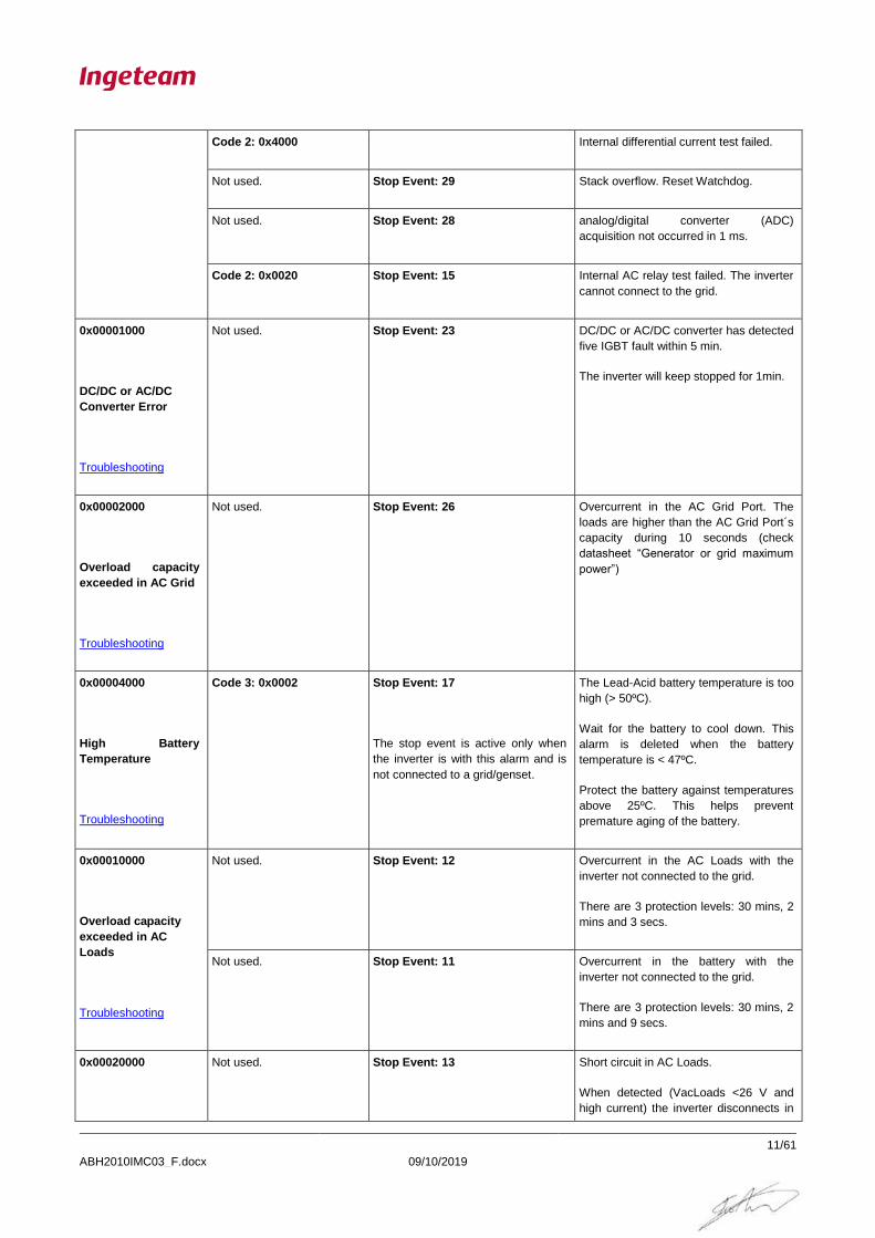
11/61
Code 2: 0x4000 Internal differential current test failed.
Not used. Stop Event: 29 Stack overflow. Reset Watchdog.
Not used. Stop Event: 28 analog/digital converter (ADC)
acquisition not occurred in 1 ms.
Code 2: 0x0020 Stop Event: 15 Internal AC relay test failed. The inverter
cannot connect to the grid.
0x00001000
DC/DC or AC/DC
Converter Error
Troubleshooting
Not used. Stop Event: 23 DC/DC or AC/DC converter has detected
five IGBT fault within 5 min.
The inverter will keep stopped for 1min.
0x00002000
Overload capacity
exceeded in AC Grid
Troubleshooting
Not used. Stop Event: 26 Overcurrent in the AC Grid Port. The
loads are higher than the AC Grid Port´s
capacity during 10 seconds (check
datasheet “Generator or grid maximum
power”)
0x00004000
High Battery
Temperature
Troubleshooting
Code 3: 0x0002 Stop Event: 17
The stop event is active only when
the inverter is with this alarm and is
not connected to a grid/genset.
The Lead-Acid battery temperature is too
high (> 50ºC).
Wait for the battery to cool down. This
alarm is deleted when the battery
temperature is < 47ºC.
Protect the battery against temperatures
above 25ºC. This helps prevent
premature aging of the battery.
0x00010000
Overload capacity
exceeded in AC
Loads
Troubleshooting
Not used. Stop Event: 12 Overcurrent in the AC Loads with the
inverter not connected to the grid.
There are 3 protection levels: 30 mins, 2
mins and 3 secs.
Not used. Stop Event: 11 Overcurrent in the battery with the
inverter not connected to the grid.
There are 3 protection levels: 30 mins, 2
mins and 9 secs.
0x00020000
Not used. Stop Event: 13 Short circuit in AC Loads.
When detected (VacLoads <26 V and
high current) the inverter disconnects in

INGECON SUN STORAGE 1PLAY
ABH2010IMC03_F.docx 09/10/2019
12/61
Short circuit in AC
Loads
Troubleshooting
40 ms.
0x00040000
PT100 sensor
Troubleshooting
Code 3: 0x0001 Not used. The PT100 temperature sensor can be
disconnected or short-circuited or cable
break.
Ensure that the battery temperature
sensor is correctly connected.
0x00080000
Communication
Error with the BMS
Troubleshooting
Code 2: 0x0200 Stop Event: 3
The stop event is active only when
the inverter is with this alarm and is
disconnected to a grid/genset.
When the inverter is disconnected to the
grid, it will stop within 5 seconds after
loss of communication occurs.
The inverter will recover automatically
when communication is established
again.
If the inverter is connected to the grid, it
will keep connected without using the
battery.
0x00100000
Wrong inverter serial
number
Troubleshooting
Not used. Not used.
This alarm is active before the
inverter start-up.
The inverter has a wrong serial number.
0x00200000
High grid voltage
Troubleshooting
Not used. Stop Event: 5
The stop event is active only when
the inverter is with this alarm, is
connected to a grid/genset and the
backup function is disabled.
Instantaneous Vac High protection:
If the backup function is enabled, the
inverter disconnects from the grid and
generates the grid itself.
If the backup function is disabled, the
inverter stops.
0x00400000
Wrong type of
battery configuration
Not used. Stop Event: 27 The inverter keeps stopped if a frame of
a Battery Management Systems (BMS)
is detected with the configuration set to
Lead Acid.
The battery settings must be corrected.

INGECON SUN STORAGE 1PLAY
ABH2010IMC03_F.docx 09/10/2019
13/61
Troubleshooting
0x00800000
BMS alarm
Troubleshooting
Code 2: 0x2000 Stop Event: 30 When the inverter is disconnected to the
grid, it will stop. The inverter will recover
automatically when alarm in the BMS
disappears.
If the inverter is connected to the grid, it
will keep connected without using the
battery.
0x01000000
Overcurrent
exceeded in PV input
Troubleshooting
Not used. Stop Event: 11 Overcurrent in the PV input. The PV
current is higher than the PV Input´s
capacity during 60 seconds (check
datasheet “PV array input (DC)”)
0x02000000
Full Battery
Discharge
Troubleshooting
Code 3: 0x0040
Low battery SOC
(SOCdescx)
Stop Event: 1
The stop event is active only when
the inverter is with this alarm and is
working in off-grid (grid/genset
disconnected).
This is because the battery is the
only energy source available to feed
the loads, but it is already to the
minimum so the inverter must stop.
It may be caused by the battery
protection, SOC <= SOCdescx
(disconnection SOC).
In three phase systems there is not SOC
estimation, so the condition is Vbat <=
Vbatdescx (disconnection Voltage).
The alarm will be active until SOC >=
SOCrecx (reconnection SOC). The
battery needs to be charged form PV or
Grid/Genset.
In three phase systems there is not SOC
estimation, so the condition is Vbat >=
Vbatrecx (reconnection Voltage).

INGECON SUN STORAGE 1PLAY
ABH2010IMC03_F.docx 09/10/2019
14/61
WARNINGS
UNIT OPERATING CODES
DESCRIPTION
Code 1: 0x0008 Internal fan has detected a fault.
The fan will keep stopped while it is
blocked.
Code 1: 0x0010 External fan has detected a fault.
The fan will keep stopped while it is
blocked.
Code 2: 0x0001 Inverter has detected high temperature in
PCB or Sink.
If the inverter is connected to the grid, it
will regulate AC output power.
Code 2: 0x0010 DC offset in the DC/AC converter current
has been compensated without enough
accuracy.
Code 2: 0x0800 Error in the phase sequence of the three-
phase system.
Inverter configurated as Phase S or
Phase T has detected error in the phase
sequence of the grid.
The inverter will not connect to the grid
while this warning is active.
Code 2: 0x1000 The digital input of the inverter has
detected an error in the status of the
external AC grid contactor.
Code 3: 0x0004
Troubleshooting
DC/DC converter cannot elevate.
Code 3: 0x0008
Troubleshooting
Synchronization with the grid not
successful.
Code 3: 0x0010 Grid Transient Disconnection in Backup
Function.
Code 3: 0x0020
Troubleshooting
Bus CAN Communication is not working
correctly.

INGECON SUN STORAGE 1PLAY
ABH2010IMC03_F.docx 09/10/2019
15/61

INGECON SUN STORAGE 1PLAY
ABH2010IMC03_F.docx 09/10/2019
16/61
4 INCIDENT WORKFLOW
This section shows the workflow diagram necessary to follow to resolve the incidents that could be detected
through the different events explained above.
HW COMPROBATIONS
HW REPLACEMENTS
CALIBRATIONS
WORKFLOW RESOLUTION
CHECKING MEASURES
MEANING OF COLOR WORKFLOW ELEMENTS
POSSIBLE ABNORMAL INVERTER SITUATION
WORKFLOW COMPROBATION
WORKFLOW INSTRUCTION
HW FAILURE

INGECON SUN STORAGE 1PLAY
ABH2010IMC03_F.docx 09/10/2019
17/61
4.1 Alarm 0x00000001, Code 2 0x0080: Stop Event 1 Vbat Low (Vmin).
ALARM 0x00000001
Code 2 0x0080 Vbat low
Fix the battery bank
Measure the Battery Voltage with a voltimeter
on the Inverter´s terminals.
Learn in 5.2.1 how to do it
Name this measure “Vbat_Inv”
Is Vbat_Inv > Vnom*0.9?
Get the Nominal Voltage of your whole Battery
Bank.
Name this value “Vnom”
Measure the Battery Voltage with a voltimeter
on the Battery Bank´s terminals.
Name this measure “Vbat”
Stop the inverter and disconnect the PV
Array from the ISS 1Play
NO Is |Vbat_Inv – Vbat| > 2V? Very Important keeping the
inverter stopped.
Check the wires between the
battery and the inverter
Is Vbat_Inv > Vbat_min?
Check the Minimum Battery Voltage on the
Inverter´s configuration
Learn in 5.4.6 how to do it
Name this value “Vbat_min”
YES
YES
Set a correct Vbat_min value in
the Inverter´s Configuration
Does that Vbat_min make sense with your battery
specifications?
NO
YES
NO
NO
YES
Obtain the State of Charge (“SOC”)
value from the Inverter´s monitoring
data
Obtain the Disconnection State of Charge
(“SOCdescx”) and Reconnection State of
Charge (“SOCrecx”) value from the
Inverter´s Configuration
Is SOC >= SOCrecx?
YES
Does SOCrecx and SOCdescx make sense for
your desired strategy?
Fully charge the battery bank to
reset the SOC estimation. For Lead
Acid Batteries, it is essential setting
correctly C20h and C5h parameters
for a good SOC estimation
See how to it in the FAQ chapter
Fix the SOCrecx and
SOCdescx settings to more
suitable ones
NO
YES
The battery bank needs to
be charged
Are battery cells functional? Learn in 5.1.2 how to do it
YES NO
Is there the Alarm 0x80000 “BMS COM” showing as
well?
Fix before the 0x80000 alarm
“BMS COM ERROR”
Does the problem
dissapear?
The problem is solved with the
FW update
YES NO
Upgrade INVERTER FW
See 5.4.7
Contact INGETEAM Technical
Support
YES
NO
YES
NO
INGECON SUN STORAGE 1PLAY
ABH2010IMC03_F.docx 09/10/2019
18/61
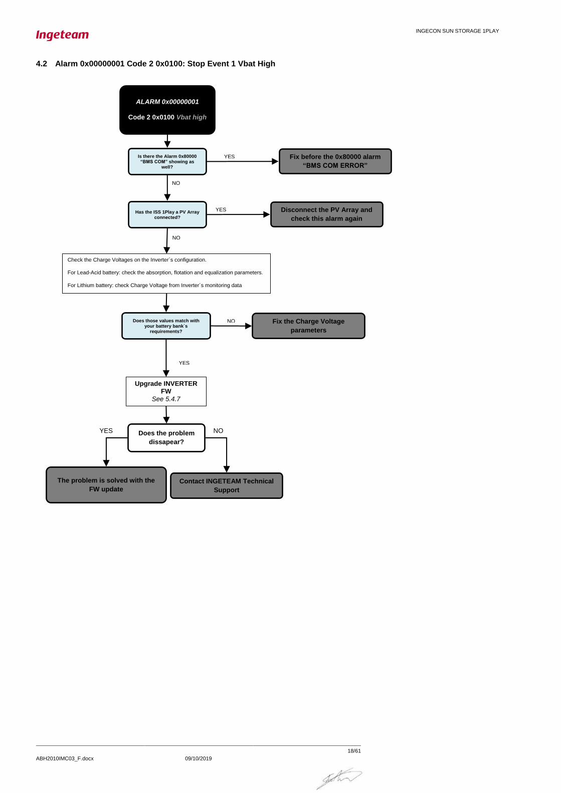
4.2 Alarm 0x00000001 Code 2 0x0100: Stop Event 1 Vbat High
ALARM 0x00000001
Code 2 0x0100 Vbat high
Check the Charge Voltages on the Inverter´s configuration.
For Lead-Acid battery: check the absorption, flotation and equalization parameters.
For Lithium battery: check Charge Voltage from Inverter´s monitoring data
Does those values match with your battery bank´s
requirements?
Fix the Charge Voltage
parameters
NO
Is there the Alarm 0x80000 “BMS COM” showing as
well?
Fix before the 0x80000 alarm
“BMS COM ERROR”
YES
Does the problem
dissapear?
The problem is solved with the
FW update
YES NO
Upgrade INVERTER FW
See 5.4.7
Contact INGETEAM Technical
Support
YES
NO
Has the ISS 1Play a PV Array connected?
Disconnect the PV Array and
check this alarm again
YES
NO

INGECON SUN STORAGE 1PLAY
ABH2010IMC03_F.docx 09/10/2019
19/61
4.3 Alarm 0x00000002 and Alarm 0x0000004
ALARM:
0x00000002 Fac out of range 0x00000004 Vac out of range
The COUNTRY/REGULATION
configured is correct?
YES
YES. IT IS “GRID”
SI The V/FSETTINGS configured are correct?
YES
NO
Access inside the inverter
Measure the Grid/Genset Voltage and Frequency on the
Inverter´s Terminal with a multimeter See 5.2.5
Set a correct COUNTRY/REGULATION
See 5.3.1
Set a correct NOMINAL GRID VOLTAGE
NOMINAL GRID FRECUENCY See 5.3.3
Set correct
GRID VAC/FAC LIMITS See 5.3.5
Does the configured Type of Grid
match with your installation?
The V/FSETTINGS match with the Genset´s datasheet?
Set a correct TYPE OF GRID See 5.3.2
NO
YES. IT IS “GENERATOR”
NO
NO Set correct GENERATOR VAC/FAC LIMITS
See 5.3.4
YES
Compare these measurements with the V/F Settings. Are they
out of limits?
Wait until the Vac or Fac returns within Limits
Contact INGETEAM Technical
Support
It might has been a transient: If your
grid is too weak, avoid sudden
connection/disconnection of big loads
Is the alarm showing now?
YES NO
NO

INGECON SUN STORAGE 1PLAY
ABH2010IMC03_F.docx 09/10/2019
20/61
4.4 Alarm 0x00000008: Stop Event 7 DC/AC Converter´s Overcurrent or Fault
ALARM Code:
0x00000008 DC/AC Overcurrent or Fault
Is it the positive or negative pole
of the PV panel (See 5.2.4) or
battery (See 5.2.2) GROUNDED?
Due to the inverter´s topology, it is NOT
ALLOWED.
Use ungrounded PV and battery solutions.
YES
Does the problem
disappear?
The problem is solved with the
FW update
YES
NO
NO
Upgrade INVERTER FW
See 5.4.7
Has Vac suffered an abrupt transient?
Try to measure the Grid´s Vac (See 5.2.5) in an oscilloscope.
Transients in the AC installation affect the inverter
NO Contact INGETEAM Technical
Support. Send them if possible a
oscilloscope capture
YES
Is the Inverter not working anymore, showing as well the Alarm 0x00001000?
Contact INGETEAM Technical
Support
YES
NO

INGECON SUN STORAGE 1PLAY
ABH2010IMC03_F.docx 09/10/2019
21/61
4.5 Alarm 0x00000010: DC/DC Converter´s Overcurrent (Stop Event 9) or Fault (Stop Event 8)
ALARM Code:
0x00000010 DC/DC Overcurrent or Fault
Is the Battery POLARITY in the
correct position on the Inverter?
Fix the Battery POLARITY
NO
Does the problem
dissapear?
The problem is solved with the
FW update
YES
YES
NO
Upgrade INVERTER FW
See 5.4.7
Which is the Stop Event?
See 5.4.4
Nº 9.
OVERCURRENT
Contact INGETEAM Technical
Support
Nº 8. IGBT
FAULT
INGECON SUN STORAGE 1PLAY
ABH2010IMC03_F.docx 09/10/2019
22/61
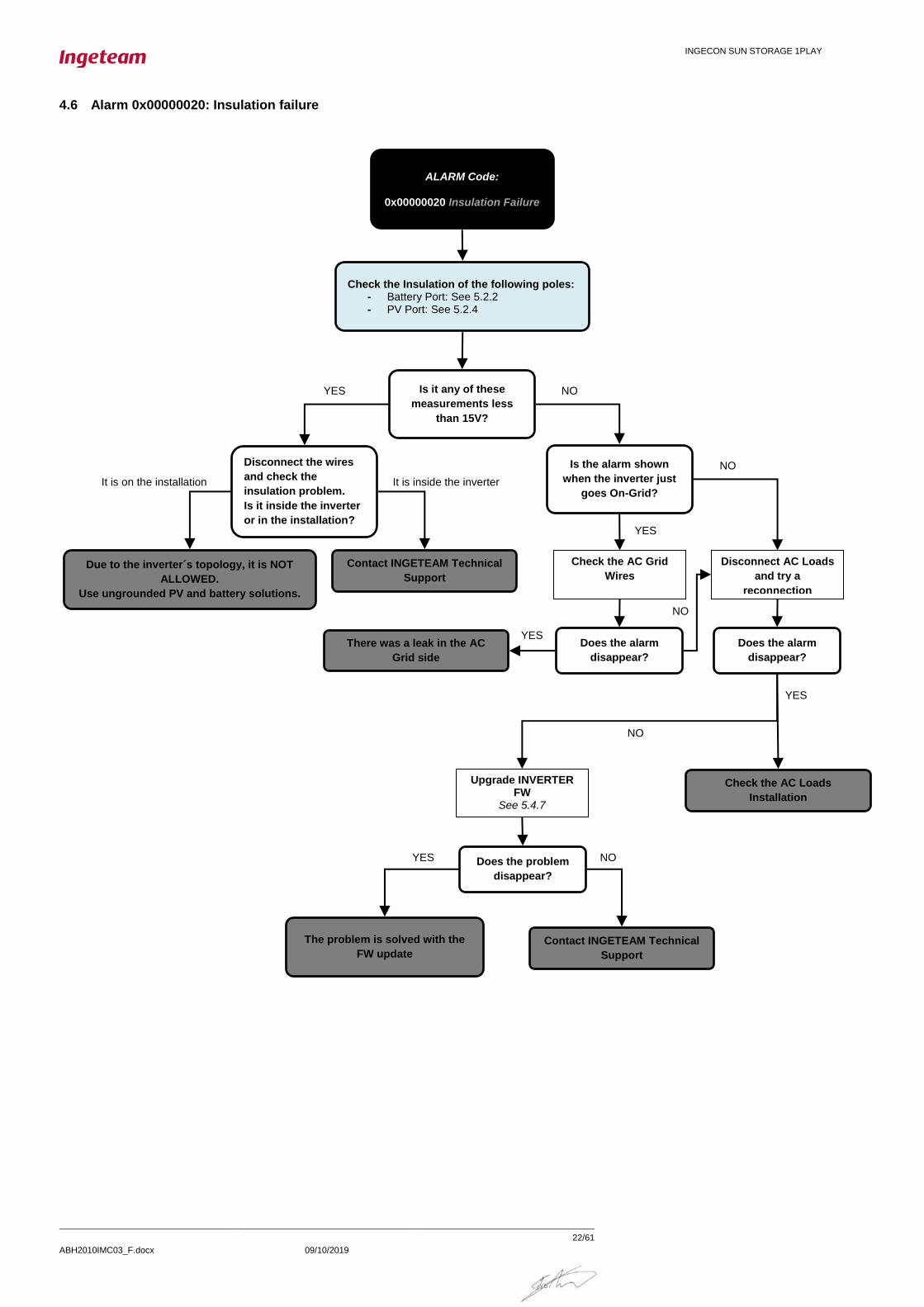
4.6 Alarm 0x00000020: Insulation failure
ALARM Code:
0x00000020 Insulation Failure
Check the Insulation of the following poles: - Battery Port: See 5.2.2 - PV Port: See 5.2.4
Is it any of these
measurements less
than 15V?
Disconnect the wires
and check the
insulation problem.
Is it inside the inverter
or in the installation?
YES
Due to the inverter´s topology, it is NOT
ALLOWED.
Use ungrounded PV and battery solutions.
It is on the installation
Is the alarm shown
when the inverter just
goes On-Grid? It is inside the inverter
Check the AC Grid
Wires Contact INGETEAM Technical
Support
Disconnect AC Loads
and try a
reconnection
NO
YES
NO
Does the alarm
disappear?
Does the alarm
disappear?
There was a leak in the AC
Grid side
YES
NO
Check the AC Loads
Installation
YES
Does the problem
disappear?
The problem is solved with the
FW update
YES NO
Upgrade INVERTER FW
See 5.4.7
Contact INGETEAM Technical
Support
NO

INGECON SUN STORAGE 1PLAY
ABH2010IMC03_F.docx 09/10/2019
23/61
4.7 Alarm 0x00000040: Stop Event 22. Synchronization alarm in 3 Phase Systems.
ALARM Code:
0x00000040 Synchronization
Before dealing with this alarm, read carefully the chapter dedicated to
three-phase systems in the “Installation and Operation Manual”
Very Important
Check the Inverter´s configuration for the “AC Phase of the Inverter”
See 5.3.7
For Single Phase Installation → Set Single Phase
For Three-Phase Installation →R,S,T. Each one for each inverter
Does the alarm
disappear?
The inverters were wrongly
configured
YES
NO
Is it any of the 3
inverters showing an
additional alarm?
Fix that alarm first YES
Which types of
Hardware do you have? See in the “Installation and
Operation” Manual How to do it
NO
- Check that the Phase of the
previous inverter is correctly
connected in J61.
- Check that the previous inverter is
Generating the expected voltage. It
can be done seeing the Inverter´s
AC Load Vac.
Are those
checking OK?
The previous inverter must be
generating and the
synchronization cable correctly
wired
- Check that the RX/TX of the
previous inverter is correctly
connected in J75.
- Check that the previous inverter is
Generating the expected voltage. It
can be done seeing the Inverter´s
AC Load Vac.
Are those
checking OK?
NO NO
3 INVERTERS WITH TYPE B
Contact INGETEAM Technical
Support
DIFFERENT
TYPES
3 INVERTERS WITH TYPE A
Disconnect all the Loads to let the
Inverters generating in open circuit
After 30 seconds, do
the 3 inverters
generate correctly?
Does the problem
disappear?
The problem is solved with the
FW update
YES NO
Upgrade INVERTER FW
See 5.4.7
Contact INGETEAM Technical
Support
YES YES
The loads transients seem to affect the
inverter. Check that they are correctly
sized. Ingeteam recommends the use of
frequency drives to avoid transient
voltage drops (2-3 seconds) during their
connection
YES NO

INGECON SUN STORAGE 1PLAY
ABH2010IMC03_F.docx 09/10/2019
24/61
4.8 Alarm 0x00000080: Temperature. Stop Events 16 and 17.
ALARM Code:
0x00000080 Temperature
The environment of the unit is appropriate as is described in the section
ENVIRONMENTAL CONDITIONS of the “Installation and Operation Manual”?
Inverter is working at not enough refrigeration or
heating conditions
RECONSIDER THE LOCATION of the unit
Has Code 1 = 0x0008 or
Code 1 = 0x0010
appeared during the
test?
Perform the Fan´s Test See 5.5.1
Check visually the fan´s. If there is an object blocking the fans, remove it.
Otherwise, Contact INGETEAM Technical Support
YES
The ventilation conduct is free of dust and the air can flow through the radiator correctly?
Clean up the inverter
NO
NO
YES
NO
Does the problem
disappear?
The problem is solved with the
FW update
YES NO
Upgrade INVERTER FW
See 5.4.7
Contact INGETEAM Technical
Support
YES
INGECON SUN STORAGE 1PLAY
ABH2010IMC03_F.docx 09/10/2019
25/61
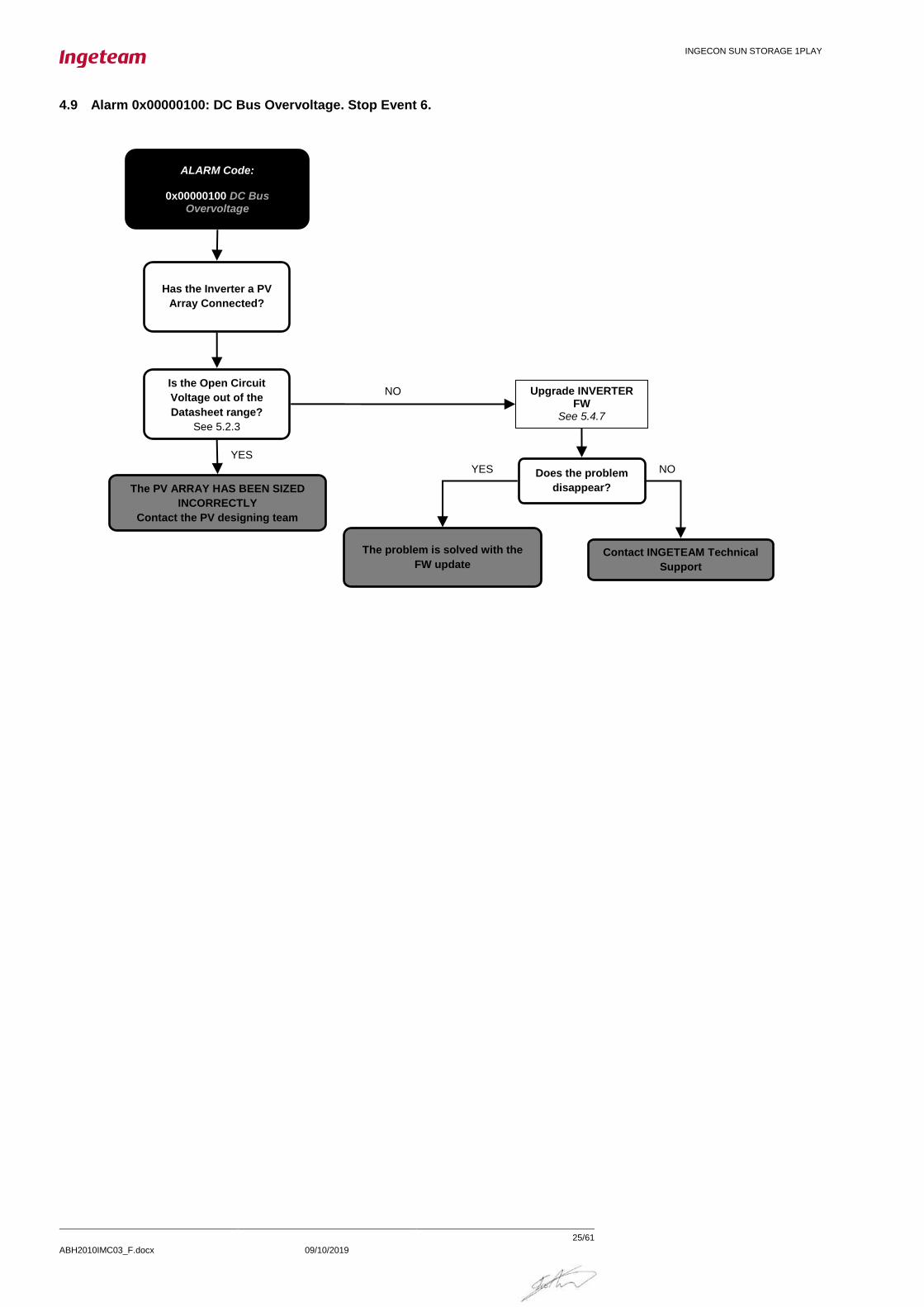
4.9 Alarm 0x00000100: DC Bus Overvoltage. Stop Event 6.
ALARM Code:
0x00000100 DC Bus Overvoltage
The PV ARRAY HAS BEEN SIZED
INCORRECTLY
Contact the PV designing team
Has the Inverter a PV
Array Connected?
NO Is the Open Circuit
Voltage out of the
Datasheet range?
See 5.2.3
YES
Does the problem
disappear?
The problem is solved with the
FW update
YES NO
Upgrade INVERTER FW
See 5.4.7
Contact INGETEAM Technical
Support

INGECON SUN STORAGE 1PLAY
ABH2010IMC03_F.docx 09/10/2019
26/61
4.10 Alarm 0x00000200: Configuration Change. Stop Event 25.
4.11 Alarm 0x00000400: Stop Inverter Command.
ALARM Code:
0x00000400 Inverter Stopped
Command the Inverter to Start See 5.5.2
Which is the Stop Event?
See 5.4.4
Code 1 and 2 also give this
information
Nº 4. DIGITAL INPUT
CODE 2 = 0x8000
Nº10. DISPLAY OR COMMS
CODE 1 = 0x2000
Fix the Digital Input Configuration. If you don´t have
any digital input, set it to No Configured
Do you really want a
digital input that stops
the inverter?
Check the Digital Input´s
configuration
NO
Is the digital input
status commanding a
stop?
Switch it to start
YES
YES
Check the digital input´s connection. There are some digital input´s, such as DRM0, that cause the stop when they are wrongly connected.
NO
ALARM Code:
0x00000200 Configuration Change
NORMAL Alarm and Stop Event due to a change in the inverter settings

INGECON SUN STORAGE 1PLAY
ABH2010IMC03_F.docx 09/10/2019
27/61
4.12 Alarm 0x00000800: HW Failure.
ALARM Code:
0x00000800 HW Failure
Which is the Stop Event?
See 5.4.4
Code 1 and 2 also give this
information
Stop Events = 24, 28 or 29
Does the problem
disappear?
The problem is solved with the
FW update
YES NO
Upgrade INVERTER FW
See 5.4.7
Contact INGETEAM Technical
Support
Code 1 = 0x0002, 0x0020, 0x0040, 0x0080, 0x0100 or 0x0200
Code 2 = 0x4000
Stop the Inverter. See 5.5.2
Very Important!
Measure the Impedance
between Loads and
Grid/Genset Ports
See 5.2.9
Is Line to Line and
Neutral to Neutral
Impedance greater
than 30kOhms?
Does your Grid
Installation use a TT or
TN type topology?
Disable partially or totally the
Relay Test.
NOTE: This instruction can be
performed only by a qualified
installer. Contact to INGETEAM
Technical Support anyway
YES
NO
TN
TT
Stop Event 15 Code 2 0x0020

INGECON SUN STORAGE 1PLAY
ABH2010IMC03_F.docx 09/10/2019
28/61
4.13 Alarm 0x00001000: Repetitive DC/DC or DC/AC Error. Stop Event 23.
4.14 Alarm 0x00002000: Overload in AC Grid Port. Stop Events 26.
ALARM Code:
0x00002000 Overload in Grid Port
Disconnect one by one the loads
connected
Does the alarm
disappear?
- Check the “Generator or grid maximum power” 1Play Datasheet - Estimate the power consumed by your loads
Is the Loads Power greater
than the AC Grid Port
capacity?
To show the alarm they must
be greater during 10 seconds
The installation is not able to
feed such a big load. Reduce
the consumption.
Contact INGETEAM Technical
Support
YES NO
YES
NO
ALARM Code:
0x00001000 Repetitive Error
This Alarm is because there has been
several consecutive Alarm 0x0008 or
Alarm 0x0010. The Inverter is kept
stopped for 1 min and then
automatically restarted. Solve Alarms
0x0008 or 0x0010

INGECON SUN STORAGE 1PLAY
ABH2010IMC03_F.docx 09/10/2019
29/61
4.15 Alarm 0x00004000: High Battery Temperature. Stop Events 17.
ALARM Code:
0x00004000 High Battery Temperature
Wait for the battery to cool down. This alarm is deleted when
the battery temperature is < 47ºC.
Protect the battery against temperatures above 25ºC. This
helps prevent premature aging of the battery.
Does the alarm
disappear?
Check the battery temperature sensor (PT100). See 5.1.3
Is the Battery Temperature
Sensor (PT100) correctly
connected?
The battery temperature has
been too high.
Contact INGETEAM Technical
Support
YES NO
YES
NO Ensure that the battery
temperature sensor (PT100)
is correctly connected.

INGECON SUN STORAGE 1PLAY
ABH2010IMC03_F.docx 09/10/2019
30/61
4.16 Alarm 0x00010000: Overload in AC Loads Port. Stop Events 11 and 12.
4.17 Alarm 0x00020000: Short circuit in AC Loads. Stop Event 13.
ALARM Code:
0x00020000 Short Circuits in Loads
Review the Loads Connected
to the Inverter. A short circuit
has been detected
Contact INGETEAM Technical
Support
Disconnect all the Loads from the Inverter´s AC Loads Port
Does the alarm
disappear?
NO
YES
ALARM Code:
0x00010000 Overload in Loads
Set correctly the parameter
Disconnect one by one the loads
connected
Does the alarm
disappear?
NO
Check the Battery´s Discharge Current on
the configuration See 5.3.8
Check the Output (AC) Current on the ISS 1Play Datasheet
Which is the Stop Event?
See 5.4.4
Stop Event 11 Stop Event 12
Is it correctly set according
with your installation
specifications?
The installation is not able to
feed such a big load. Reduce
the consumption.
Contact INGETEAM Technical
Support
YES NO
YES

INGECON SUN STORAGE 1PLAY
ABH2010IMC03_F.docx 09/10/2019
31/61
4.18 Alarm 0x00040000: PT100 Temperature sensor.
ALARM Code:
0x00040000 PT100 Sensor
This Alarm is because there is a short
circuit or cable break in the battery
temperature sensor.

INGECON SUN STORAGE 1PLAY
ABH2010IMC03_F.docx 09/10/2019
32/61
4.19 Alarm 0x00080000 and 0x00400000: Communication Error with the BMS.
ALARM Code:
0x00080000 Battery Com Error 0x00400000 Wrong type of battery config
Review you type of battery. Set it
to No configured if there is no
battery or to Lead Acid for
Batteries without BMS
See 5.3.9
Have you got a
battery with BMS?
NO
YES
Is the type of
Battery Correctly
Configured?
See 5.3.9
Check the communication between the Battery and the Inverter. See 5.1.3
Was it correctly done? The communication was not
correctly wired
Set a battery type according
with the battery connected
NO
NO
Is the display
working correctly?
See 5.1.4
YES
Contact INGETEAM Technical
Support
NO
Does the problem
disappear?
The problem is solved with the
FW update
YES NO
Upgrade INVERTER FW
See 5.4.7
Contact INGETEAM Technical
Support
YES
Which protocol is used to communicate the BMS
Information to the Inverter?
CAN RS485
Does the BMS refresh
the communication
within the timeout?
Check the RS485 Communication Timeout on the ISS 1Play´s Configuration.
See 5.3.10
NO
YES YES
Set a correct timeout
according to the BMS
communication period.

INGECON SUN STORAGE 1PLAY
ABH2010IMC03_F.docx 09/10/2019
33/61
4.20 Alarm 0x00100000: Wrong Inverter Serial Number.
4.21 Alarm 0x00200000: High Instantaneous Grid Voltage. Stop Event 5.
ALARM Code:
0x00200000 Instantaneous High Vac
One of the possible causes could be that the Grid´s Circuit Breaker is opened.
Check your grid installation
and switch on again the Circuit
Breaker
Is the Grid´s Circuit
Breaker tripped?
YES
NO
The Grid voltage is higher than
the maximum limit allowed by
the grid code.
ALARM Code:
0x00100000 Wrong Inverter Serial Number
Check the Inverter´s Serial Number reading it with Ingecon Sun Manager or Display
Does it match with
the one in the
rating plate?
Contact INGETEAM Technical
Support indicating the result of
this question
YES
NO
INGECON SUN STORAGE 1PLAY
ABH2010IMC03_F.docx 09/10/2019
34/61
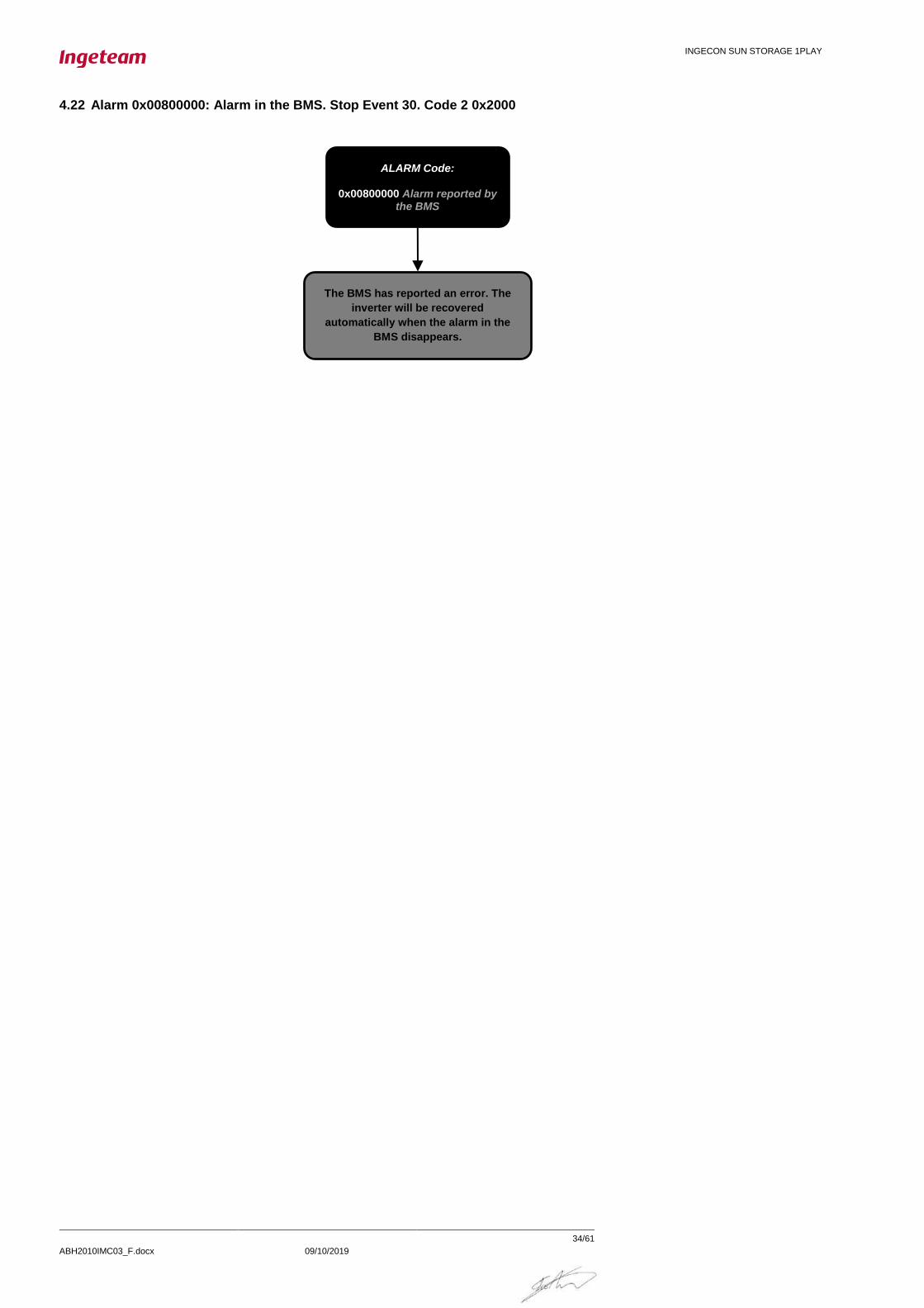
4.22 Alarm 0x00800000: Alarm in the BMS. Stop Event 30. Code 2 0x2000
ALARM Code:
0x00800000 Alarm reported by the BMS
The BMS has reported an error. The
inverter will be recovered
automatically when the alarm in the
BMS disappears.

INGECON SUN STORAGE 1PLAY
ABH2010IMC03_F.docx 09/10/2019
35/61
4.23 Alarm 0x01000000: Overcurrent in PV array input. Stop Event 11.
4.24 Alarm 0x02000000, Code 3 0x0040: Stop Event 1 Battery SOC Low (SOCdescx).
ALARM 0x02000000
Code 3 0x0040 Battery
SOC low
Obtain the State of Charge (“SOC”)
value from the Inverter´s monitoring
data
Obtain the Disconnection State of Charge
(“SOCdescx”) and Reconnection State of
Charge (“SOCrecx”) value from the
Inverter´s Configuration
Is SOC >= SOCrecx?
YES
Does SOCrecx and SOCdescx make sense for
your desired strategy?
Fully charge the battery bank to
reset the SOC estimation. For Lead
Acid Batteries, it is essential setting
correctly C20h and C5h parameters
for a good SOC estimation
See how to it in the FAQ chapter
Fix the SOCrecx and
SOCdescx settings to more
suitable ones
NO
YES
Is there the Alarm 0x80000 “BMS COM” showing as
well?
Fix before the 0x80000 alarm
“BMS COM ERROR”
Does the problem
dissapear?
The problem is solved with the
FW update
YES NO
Upgrade INVERTER FW
See 5.4.7
Contact INGETEAM Technical
Support
YES
NO
NO
ALARM Code:
0x01000000 Over-current in PV array input
PV ARRAY SIZED INCORRECTLY. The
PV current is higher than the PV
Input´s capacity during 60 seconds
(check datasheet “PV array input
(DC)”)

INGECON SUN STORAGE 1PLAY
ABH2010IMC03_F.docx 09/10/2019
36/61
4.25 Warning: Code 3 0x0004: DC/DC converter cannot elevate.
4.26 Warning: Code 3 0x0008: Synchronization with the grid not successful.
Warning Code 3:
0x0008 Synchronization with the grid not successful
The Grid or Generator voltage is
sporadically outside the limiting value.
Set the limiting values for voltage and
frequency of the grid/genset.
Warning Code 3:
0x0004 DC/DC converter cannot elevate
Does the problem
disappear?
The problem is solved with the
FW update
YES NO
Upgrade INVERTER FW
See 5.4.7
Contact INGETEAM Technical
Support
One of the possible causes could be that a high output power in AC LOAD may lead to the inverter not being able to raise the loads voltage to the grid
voltage.
Reduce the power of the loads.
Is the AC LOADS´s
power higher than
battery can deliver?
YES
NO

INGECON SUN STORAGE 1PLAY
ABH2010IMC03_F.docx 09/10/2019
37/61
4.27 Warning: Code 3 0x0020: Bus CAN Communication Error.
Warning Code 3:
0x0020 Bus CAN Comms Error
Does the problem
disappear?
Solve those alarms first.
Is this warning together with
- 0x00080000 Battery Com Error - 0x00400000 Wrong type of battery config
alarms?
NO
YES
Solve the config first. If any of
those devices has no
firmware, please update it
YES
Contact INGETEAM Technical
Support
Is the Battery Config the same both in
Display and Inverter? See 5.3.11
NO
NO
Check Internal Bus CAN Wire See 5.1.6
Is the display
working correctly?
See 5.1.4
YES
INGECON SUN STORAGE 1PLAY
ABH2010IMC03_F.docx 09/10/2019
38/61
5 TRAINING INSTRUCTIONS
5.1 CHECKING MEASURES
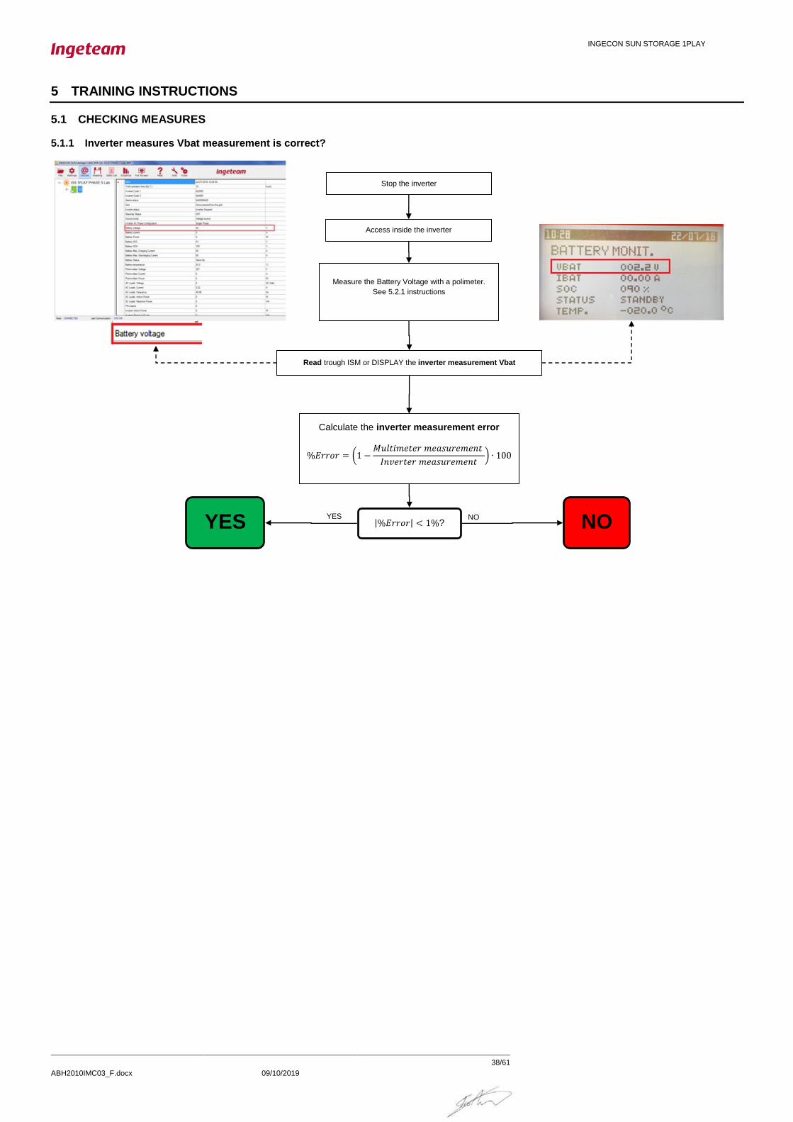
5.1.1 Inverter measures Vbat measurement is correct?
|%𝐸𝑟𝑟𝑜𝑟| < 1%?
Calculate the inverter measurement error
%𝐸𝑟𝑟𝑜𝑟 = (1 −𝑀𝑢𝑙𝑡𝑖𝑚𝑒𝑡𝑒𝑟 𝑚𝑒𝑎𝑠𝑢𝑟𝑒𝑚𝑒𝑛𝑡
𝐼𝑛𝑣𝑒𝑟𝑡𝑒𝑟 𝑚𝑒𝑎𝑠𝑢𝑟𝑒𝑚𝑒𝑛𝑡) ∙ 100
NO YES
Read trough ISM or DISPLAY the inverter measurement Vbat
YES NO
Measure the Battery Voltage with a polimeter.
See 5.2.1 instructions
Access inside the inverter
Stop the inverter

INGECON SUN STORAGE 1PLAY
ABH2010IMC03_F.docx 09/10/2019
39/61
5.1.2 All battery cells are functional?
5.1.3 Check the communication between de battery and the inverter.
The communication between the battery and the ISS 1Play can be with CAN or RS485 Protocol.
Batteries with CAN Protocol
This point asks for reviewing the wiring of the CAN communication between the battery and the inverter. For a correct communication the following points must be all
right:
- The battery and the inverter must be switched ON.
- The wiring must be well connected. Check the “Installation and Operation Manual” of the Inverter to see in which position are placed. Compare it with the
Battery´s BMS´s wire convention.
For some batteries, such as LG Resu model, Ingeteam released a dedicated commissioning guide. For getting those guides, Contact with Ingeteam
Technical Service.
Depending on the CAN Battery connector, the text on the PCB change.
Batteries with RS485 Protocol
For a correct communication the following points must be all right:
- The battery and the inverter must be switched ON.
- The RS485 wiring must be well connected in the Inverter´s communication board. For further details, Contact Ingeteam Technical Service.
5.1.4 Check that the display is working correctly.
The display is connected to the inverter´s Printed Circuit Board through a set of wires to provide the electrical power supply and the CAN communication.
When a display is not working correctly, it is not turned on or just after turning on it starts with the hour at “00:00”.
A battery cell is not defective?
0,9*VnomCell > Vcell > 1,4*VnomCell
Get the Nominal Cell Voltage
from the Battery´s Datasheet
Name this “VnomCell”
YES NO
Measure with a voltimeter each battery cell
Name this “Vcell”
Keep the inverter stopped.
YES NO

INGECON SUN STORAGE 1PLAY
ABH2010IMC03_F.docx 09/10/2019
40/61
5.1.5 Check the battery temperature sensor (PT100).
This point asks for reviewing the wiring of the battery temperature sensor. For a correct temperature of the battery bank the following points must be all right:
- The wiring must be well connected. Check the “Installation and Operation Manual” of the Inverter to see in which position are placed.
- If the type of PT100 sensor is 2-wires, it is necessary short circuit the R-R pins and the PT100 (2-wires) is installed between R-W pins.
- If the type of PT100 sensor is 3-wires, the PT100 is installed in R-R-W pins.
5.1.6 Check internal CAN Bus Wire.
The internal CAN Bus Wire connects the main PCB (connector J14) to the control PCB (connector J19). Check that this wire is OK.

INGECON SUN STORAGE 1PLAY
ABH2010IMC03_F.docx 09/10/2019
41/61
5.2 MEASUREMENTS ON INVERTER
NOTE: The multimeter have to be connected on the measuring points during the entire process,
calibration or checking inverter measures.
Insert and remove the multimeter on these points could affect the measures because of its internal
impedance.
All the measurements must be done with the inverter powered up, if other thing is not expressly
indicated. See the Safety Requiremets in the annex.
5.2.1 Measure the Battery Voltage with a voltimeter on the Inverter´s terminals.
Depending on the type of Battery Connector, the test point to place the voltimeter changes:
5.2.2 Check the Battery´s Insulation.
This measuremen´st goal is to check the voltage between the Positive and Negative to Ground.
Depending on the type of Battery Connector, the test point to place the voltimeter changes:
5.2.3 Measure PV panel´s open circuit Voltage.
In order to have an accessible point to place the voltimeter´s probe, it is recommended to disconnect the
multicontacts. To avoid an electric arc, put before the disconnection the inverter in Manual Stop.
Measure the voltage between the two Multicontact aereal conectors.

INGECON SUN STORAGE 1PLAY
ABH2010IMC03_F.docx 09/10/2019
42/61
5.2.4 Check the PV Array´s Insulation.
This measurement´s goal is to check the voltage between the Positive and Negative to Ground.
In order to have an accessible point to place the voltimeter´s probe, it is recommended to disconnect the
multicontacts. To avoid an electric arc, put before the disconnection the inverter in Manual Stop.
5.2.5 Measure the Grid/Genset Voltage and Frequency on the Inverter´s terminals.
Depending on the type of Grid Connector, the test point to place the voltimeter changes:
5.2.6 Check the Load Port´s Insulation.
This measurement´s goal is to check the voltage between the Line and Neutral to Ground.

INGECON SUN STORAGE 1PLAY
ABH2010IMC03_F.docx 09/10/2019
43/61
Depending on the type of Battery Connector, the test point to place the voltimeter changes:
5.2.7 Check the Grid/Genset Port´s Insulation
This measurement´s goal is to check the voltage between the Line and Neutral to Ground.
Depending on the type of Battery Connector, the test point to place the voltimeter changes:
5.2.8 Measure the Voltage between Loads and Grid/Genset Ports
Measure the Voltage between Loads and Grid/Genset Ports. Do it without disconnecting the Loads Port and
Grid/Genset Port´s wires but with the inverter in Manual Stopped (Very Important!).
Depending on the type of Battery Connector, the test point to place the voltimeter changes:
With the voltmeter in red is measured the L-L and with the one in black the N-N
5.2.9 Measure the Impedance between Loads and Grid/Genset Ports
Measure the Impedance between Loads and Grid/Genset Ports. Do it without disconnecting the Loads Port
and Grid/Genset Port´s wires but with the inverter in Manual Stopped (Very Important!).

INGECON SUN STORAGE 1PLAY
ABH2010IMC03_F.docx 09/10/2019
44/61
Depending on the type of Battery Connector, the test point to place the voltimeter changes:
With the ohmeter in red is measured the L-L and with the one in black the N-N

INGECON SUN STORAGE 1PLAY
ABH2010IMC03_F.docx 09/10/2019
45/61
5.2.10 Measure the DC/AC Inductor´s Current.
Embrace the wire of the picture with a current probe:

INGECON SUN STORAGE 1PLAY
ABH2010IMC03_F.docx 09/10/2019
46/61
5.3 BASIC CONFIGURATION CHANGES
5.3.1 Set COUNTRY/REGULATION
Select the country where the inverter will be installed. If the country is not on the list, select Worldwide. Then,
select the applicable regulation.
This can be done using the “Ingecon Sun Manager” software package (downloadable on www.ingeteam.com)
or through the display:
Using Ingecon Sun Manager:
Settings → 4.- GRID SETTINGS
Figure 1: Country Regulation Selection on Ingecon Sun Manager
Click on the “Send” button. A screen informing that the configuration was successfully saved must appear
when the settings are correctly applied to the inverter.
Using Display:
To perform any configuration change through the display, the required installer password must be entered on:
MAIN MENU > CONFIGURATION > ENTER PASSWORD
The password (0332) is indicated on the “Installation and Operation Manual”, on the chapter dedicated to
configuration.
When the permission is given, go to:
MAIN MENU > CONFIGURATION > GRID/GENSET > TYPE OF GRID > GRID > COUNTRY REGULATION
Confirm the desired selection by pressing the “OK” button. A message to confirm the modification will pop up.
A final screen that shows that the process has been completed will be shown on the display.
5.3.2 Set TYPE OF GRID
Select the type of grid that the ISS 1PLAY STORAGE is connected to in this moment.
This can be done using the “Ingecon Sun Manager” software package (downloadable on www.ingeteam.com)
or through the display:
Using Ingecon Sun Manager:
Settings → 2.-AC INSTALLATION TYPE: Type of Grid
Click on the “Send” button. A screen informing that the configuration was successfully saved must appear
when the settings are correctly applied to the inverter.
Using Display:
To perform any configuration change through the display, the required installer password must be entered on:
MAIN MENU > CONFIGURATION > ENTER PASSWORD

INGECON SUN STORAGE 1PLAY
ABH2010IMC03_F.docx 09/10/2019
47/61
The password (0332) is indicated on the “Installation and Operation Manual”, on the chapter dedicated to
configuration.
When the permission is given, go to:
MAIN MENU > CONFIGURATION > GRID/GENSET > TYPE OF GRID
Confirm the desired selection by pressing the “OK” button. A message to confirm the modification will pop up.
A final screen that shows that the process has been completed will be shown on the display.
5.3.3 Set NOMINAL VAC AND FAC
Selecting a correct nominal AC Voltage and Frequency are essential because otherwise some
malfunctionings may occur.
This can be done using the “Ingecon Sun Manager” software package (downloadable on www.ingeteam.com)
or through the display:
Using Ingecon Sun Manager:
Settings → 2.- AC INSTALLATION TYPE: Nominal Voltage
Settings → 2.- AC INSTALLATION TYPE: Nominal Frequency
Click on the “Send” button. A screen informing that the configuration was successfully saved must appear
when the settings are correctly applied to the inverter.
Using Display:
To perform any configuration change through the display, the required installer password must be entered on:
MAIN MENU > CONFIGURATION > ENTER PASSWORD
The password (0332) is indicated on the “Installation and Operation Manual”, on the chapter dedicated to
configuration.
When the permission is given, go to:
MAIN MENU > CONFIGURATION > INVERTER > RMS VOLTAGE
MAIN MENU > CONFIGURATION > INVERTER > FREQUENCY
Confirm the desired selection by pressing the “OK” button. A message to confirm the modification will pop up.
A final screen that shows that the process has been completed will be shown on the display.
5.3.4 Set GENERATOR VAC/FAC SETTINGS
Selecting a correct AC Voltage and Frequency Limits are essential for avoiding malfunctioning and protecting
the genset.
This can be done using the “Ingecon Sun Manager” software package (downloadable on www.ingeteam.com)
or through the display:
Using Ingecon Sun Manager:
Settings → 3.- GENERATOR SETTINGS

INGECON SUN STORAGE 1PLAY
ABH2010IMC03_F.docx 09/10/2019
48/61
Set there the Generator parameters according to the one you are using.
Click on the “Send” button. A screen informing that the configuration was successfully saved must appear
when the settings are correctly applied to the inverter.
Using Display:
To perform any configuration change through the display, the required installer password must be entered on:
MAIN MENU > CONFIGURATION > ENTER PASSWORD
The password (0332) is indicated on the “Installation and Operation Manual”, on the chapter dedicated to
configuration.
When the permission is given, go to:
MAIN MENU > CONFIGURATION > GRID/GENSET > TYPE OF GRID > GENERATOR
Set there the Generator parameters according to the one you are using.
Confirm the desired selection by pressing the “OK” button. A message to confirm the modification will pop up.
A final screen that shows that the process has been completed will be shown on the display.
5.3.5 Set GRID VAC/FAC SETTINGS
Selecting a correct AC Voltage and Frequency Limits are essential for avoiding malfunctioning and complying
with the grid standard.
This can be done using the “Ingecon Sun Manager” software package (downloadable on www.ingeteam.com)
or through the display:
Using Ingecon Sun Manager:
Settings → 4- GRID SETTINGS
Check all that are the Grid Settings are correct. Bear in mind that the values are referred to the Nominal
Voltage and Frequency.
Click on the “Send” button. A screen informing that the configuration was successfully saved must appear
when the settings are correctly applied to the inverter.
Using Display:
To perform any configuration change through the display, the required installer password must be entered on:
MAIN MENU > CONFIGURATION > ENTER PASSWORD
The password (0332) is indicated on the “Installation and Operation Manual”, on the chapter dedicated to
configuration.
When the permission is given, go to:
MAIN MENU > CONFIGURATION > GRID/GENSET > TYPE OF GRID > GRID >V/F SETTINGS
Check all that all the Grid Settings are correct and then confirm the desired selection by pressing the “OK”
button. A message to confirm the modification will pop up. A final screen that shows that the process has
been completed will be shown on the display.
INGECON SUN STORAGE 1PLAY
ABH2010IMC03_F.docx 09/10/2019
49/61
5.3.6 Set BATTERY CAPACITY VALUES (C20h and C5h)
In the batteries without Battery Management System (BMS), such as the Lead Acid ones, the State of Charge
(SOC) estimation must be made by the inverter. In order to do it correctly, it is essential setting correctly the
C20h and C5h parameters.
This can be done using the “Ingecon Sun Manager” software package (downloadable on www.ingeteam.com)
or through the display:
Using Ingecon Sun Manager:
Settings → 4- GRID SETTINGS
Check all that are the Grid Settings are correct. Bear in mind that the values are referred to the Nominal
Voltage and Frequency.
Click on the “Send” button. A screen informing that the configuration was successfully saved must appear
when the settings are correctly applied to the inverter.
Using Display:
To perform any configuration change through the display, the required installer password must be entered on:
MAIN MENU > CONFIGURATION > ENTER PASSWORD
The password (0332) is indicated on the “Installation and Operation Manual”, on the chapter dedicated to
configuration.
When the permission is given, go to:
MAIN MENU > CONFIGURATION > GRID/GENSET > TYPE OF GRID > GRID >V/F SETTINGS
Check all that all the Grid Settings are correct and then confirm the desired selection by pressing the “OK”
button. A message to confirm the modification will pop up. A final screen that shows that the process has
been completed will be shown on the display.
5.3.7 Set Inverter´s configuration for the AC Phase of the Inverter
This parameter indicates if the inverter is installed in a Single Phase Installation or in a Three Phase One.
In the last case, the phase in which the inverter is installed must be specified (R,S,T). So it must be checked
in the 3 inverters.
This can be done using the “Ingecon Sun Manager” software package (downloadable on www.ingeteam.com)
or through the display:
Using Ingecon Sun Manager:
Settings → 2- AC INSTALLATION TYPE → AC Phase Inverter
Click on the “Send” button. A screen informing that the configuration was successfully saved must appear
when the settings are correctly applied to the inverter.
Using Display:
To perform any configuration change through the display, the required installer password must be entered on:
INGECON SUN STORAGE 1PLAY
ABH2010IMC03_F.docx 09/10/2019
50/61
MAIN MENU > CONFIGURATION > ENTER PASSWORD
The password (0332) is indicated on the “Installation and Operation Manual”, on the chapter dedicated to
configuration.
When the permission is given, go to:
MAIN MENU > CONFIGURATION > INVERTER > AC PHASE
Check all that all the Grid Settings are correct and then confirm the desired selection by pressing the “OK”
button. A message to confirm the modification will pop up. A final screen that shows that the process has
been completed will be shown on the display.
5.3.8 Check and Change BATTERY´S MAXIMUM DISCHARGING CURRENT SETTING
Reading the Maximum Discharging current for the Battery
Read the Input Register 30021. It can be done with the Manager searching the name
“Battery.Max.Discharging Current” in Online Data Section.
Changing the Maximum Discharging current for the Battery
The Maximum Discharging Current is specified in the configuration for Lead Acid Batteries (Using Ingecon
Sun Manager: Settings → 1.1. - Lead Acid Battery Settings: Max Discharge current) or is given by the BMS for
Lithium Batteries.
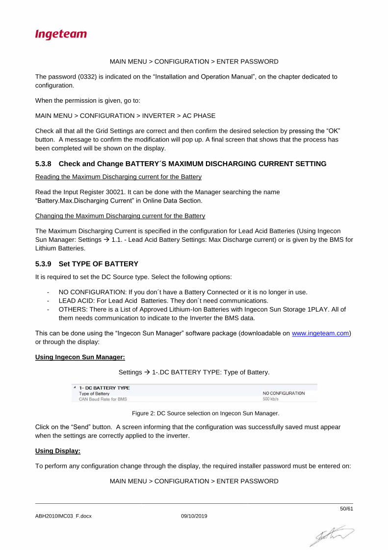
5.3.9 Set TYPE OF BATTERY
It is required to set the DC Source type. Select the following options:
- NO CONFIGURATION: If you don´t have a Battery Connected or it is no longer in use.
- LEAD ACID: For Lead Acid Batteries. They don´t need communications.
- OTHERS: There is a List of Approved Lithium-Ion Batteries with Ingecon Sun Storage 1PLAY. All of
them needs communication to indicate to the Inverter the BMS data.
This can be done using the “Ingecon Sun Manager” software package (downloadable on www.ingeteam.com)
or through the display:
Using Ingecon Sun Manager:
Settings → 1-.DC BATTERY TYPE: Type of Battery.
Figure 2: DC Source selection on Ingecon Sun Manager.
Click on the “Send” button. A screen informing that the configuration was successfully saved must appear
when the settings are correctly applied to the inverter.
Using Display:
To perform any configuration change through the display, the required installer password must be entered on:
MAIN MENU > CONFIGURATION > ENTER PASSWORD
INGECON SUN STORAGE 1PLAY
ABH2010IMC03_F.docx 09/10/2019
51/61
The password (0332) is indicated on the “Installation and Operation Manual”, on the chapter dedicated to
configuration.
When the permission is given, go to:
MAIN MENU > CONFIGURATION > BATTERY
Confirm the desired selection by pressing the “OK” button. A message to confirm the modification will pop up.
A final screen that shows that the process has been completed will be shown on the display.
5.3.10 Check the RS485 Communication Timeout.
For Batteries that use RS485 protocol, it is necessary updating the communication within the configured
Timeout.
This timeout can be checked or configured with Ingecon Sun Manager.
Settings → 8.1-.Communication Settings: Timeout for Grid Support Limit
The default value is 1800 ms.
Click on the “Send” button. A screen informing that the configuration was successfully saved must appear
when the settings are correctly applied to the inverter.
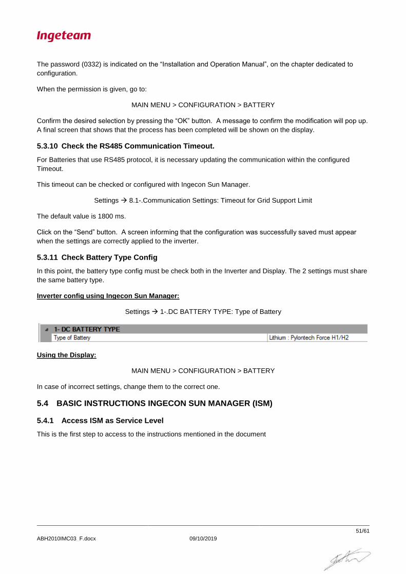
5.3.11 Check Battery Type Config
In this point, the battery type config must be check both in the Inverter and Display. The 2 settings must share
the same battery type.
Inverter config using Ingecon Sun Manager:
Settings → 1-.DC BATTERY TYPE: Type of Battery
Using the Display:
MAIN MENU > CONFIGURATION > BATTERY
In case of incorrect settings, change them to the correct one.
5.4 BASIC INSTRUCTIONS INGECON SUN MANAGER (ISM)
5.4.1 Access ISM as Service Level
This is the first step to access to the instructions mentioned in the document

INGECON SUN STORAGE 1PLAY
ABH2010IMC03_F.docx 09/10/2019
52/61
5.4.2 Sending MODBUS COMANDS via ISM
(*)Inverter node number HEXADECIMAL
Ej: Inverter Node 1
Press ENTER
Sending command through ISM console TOOLS → CONSOLA
Correct answer frame
ingeconauth Password
Acces as Sevice Level FILE → ACCESS LEVEL

INGECON SUN STORAGE 1PLAY
ABH2010IMC03_F.docx 09/10/2019
53/61
5.4.3 Downloading datalogger through ISM
Select the day and click Download
Showing datalogger trough ISM DATA LIST
Downloading datalogger and identify the alarms READING
Alarm, Codes and StopEvents

INGECON SUN STORAGE 1PLAY
ABH2010IMC03_F.docx 09/10/2019
54/61
5.4.4 Identify STOP REASON through ISM
Identify STOP REASON Data List → Datalogger
Stop events field is a 30 bit variable. Each bit defines a stop reason, starting from the least significant bit
(LSB).
NOTE: the first bit means the first stop reason
Example, in the picture above the stop reason 10 is indicated.

INGECON SUN STORAGE 1PLAY
ABH2010IMC03_F.docx 09/10/2019
55/61
5.4.5 Read/Set the INVERTER SERIAL NUMBER through ISM
Read/Set the serial number TOOLS → SET SERIAL NUMBER
To send a new S/N
NOTE: All
configuration
parameters will be
erased
After changing de S/N the inverter configuration must be reloaded

INGECON SUN STORAGE 1PLAY
ABH2010IMC03_F.docx 09/10/2019
56/61
5.4.6 Read/Set CONFIGURATION PARAMETERS trough ISM
Read INGECON SUN Settings Right click on INVERTER → INGECON SUN settings
SEND button have to be pressed for the change to be effective
Press READ to see the actual inverter configuration
INGECON SUN STORAGE 1PLAY
ABH2010IMC03_F.docx 09/10/2019
57/61
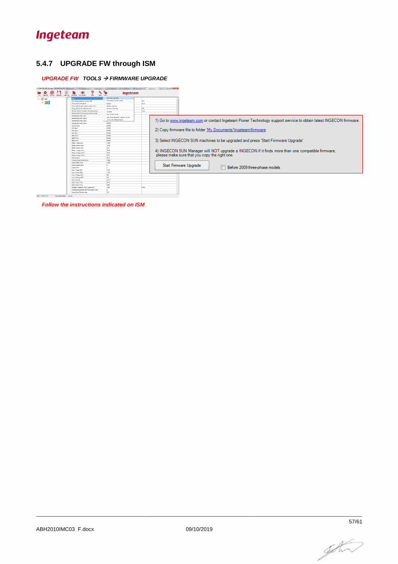
5.4.7 UPGRADE FW through ISM
UPGRADE FW TOOLS → FIRMWARE UPGRADE
Follow the instructions indicated on ISM

Ingeteam Power Technology S. A. ABH2010IMC03_F.docx
5.5 OTHER TESTS
5.5.1 Fan´s Test
Perform this test to check the unit´s fans. When the test is finished, they will be switched off automatically.
This can be done with Ingeteam Commands or through the display:
Ingeteam Commands:
Send the command NUMBER 32 to launch the test.
Using Display:
The path for launching the test is the following:
MAIN MENU > MORE OPTIONS > TEST FANS
Press “OK” to confirm.
5.5.2 Start/Stop Inverter
The inverter can be commanded to Start or Stop. This can be done with Ingeteam Commands or through the
display:
Ingeteam Commands:
Send the following commands:
o NUMBER 5 to Stop the Inverter.
o NUMBER 6 to Start the Inverter.
Using Display:
The path for launching the test is the following:
MAIN MENU > START/STOP
Press “OK” to confirm.

INGECON SUN STORAGE 1PLAY
ABH2010IMC03_F.docx 09/10/2019
59/61
6 ANEX
6.1 Safety requirements

INGECON SUN STORAGE 1PLAY
ABH2010IMC03_F.docx 09/10/2019
60/61

INGECON SUN STORAGE 1PLAY
ABH2010IMC03_F.docx 09/10/2019
61/61
6.2 Required elements
6.2.1 Instrumentation
- Multimeter (Minimun requirements: 600V Cat IV / 1000V Cat III)
6.2.2 Documentation
- Installation and Operation Manuals ABH2013 for Sun Storage 1PLAY.
- Frequently Asked Questions FAQ Guide for Sun Storage 1PLAY.
- Technical guide for installations with INGECON SUN STORAGE 1Play.
6.2.3 PC Software
- Ingecon Sun Manager (downloadable on www.ingeteam.com).
6.2.4 Accesories
- Last versión Inverter FW
- Last versión Display FW