Embed Size (px)
Citation preview

~Alamos NATIONAL LABORATORY
Risk Reduction & Environmental Stewardship Division Water Quality & Hydrology Group (RRES-WQH) PO Box 1663, MS K497 Los Alamos, New Mexico 87545
(505) 665-1859/Fax: (505) 665-9344
Mr. Kevin Krause Environmental Scientist New Mexico Environment Department Hazardous Waste Bureau P.O. Box 26110
SUBJECT:
Dear Mr. Krause:
Date: May 30,2003 Refer to: RRES-WQH: 03-117
On April3, 2003, the Laboratory's Water Quality and Hydrology Group (RRES-WQH) notified your office of the discovery of diesel contaminated soil during the installation of cathodic protection near the TA-3-26 Power Plant Aboveground Storage Tank (AST). This notification was pursuant to the New Mexico Water Quality Control Commission (NMWQCC) Regulations (20 NMAC 6.2). As part of the associated initial assessments, the Laboratory obtained contract services to conduct integrity testing on the tank. The following tests were conducted on the T A-3-26 AST:
• Floor Ultrasonic Thickness Measurements • Tank Floor Elevation Measurements • Visual Inspection of the RoofUnderside
The "In-Service Internal Floor Inspection Report" provides information on the tests conducted and associated conclusions/results. Test conclusions of this report indicate that no floor integrity issues were detected (Please see Enclosure 1).
Please contact Mark Haagenstad at (505) 665-2014 or Mike Saladen at (505) 665-6085 should you have any questions on this report.
Sincerely,
Steven Rae Group Leader Water Quality & Hydrology Group
An Equal Opportunity Employer I Operated by the University
@ Printed on Recycled Paper 1/ll/1/lllllllllllllllllll/111 5708

Mr. Kevin Krause RRES-WQH:03-117
SR:MH/tml
Enclosures: a/s
- 2-
Cy: John Young, NMED-HWB, Santa Fe, NM, w/enc. Vickie Maranville, NMED-HWB, Santa Fe, NM, w/enc. Steve Y anicak, NMED-OB, w/enc., MS J993 Joseph Vozella, DOE-OLASO, w/o enc., MS A316 Gene Turner, DOE-OLASO, w/enc., MS A316 Tony Stanford, FWO-DO, w/o enc., MS K492 David Padilla, FWO-UI, w/o enc., MS K718 Jerome Gonzales, FWO-UI, w/enc., MS K718 Beverly Ramsey, RRES-DO, w/o enc., MS J591 Kenneth Hargis, RRES-DO, w/o enc., MS J591 Tori George, RRES-DO, w/o enc., MS J591 Doug Stavert, RRES-EP, w/o enc., MS J591 Mike Saladen, RRES-WQH, w/enc., MS K497 Mark Haagenstad, RRES-WQH, w/enc., MS K497 Suzanne Moore, KSL-HENV, w/enc., MS A199 Bruce Baumgartner, KSL-HENV, w/enc. MS A199 RRES-WQH File, w/enc., MS K497 IM-5, w/enc., MS AlSO
An Equal Opportunity Employer I Operated by the University of California
@ Printed on Recycled Paper
May 30,2003
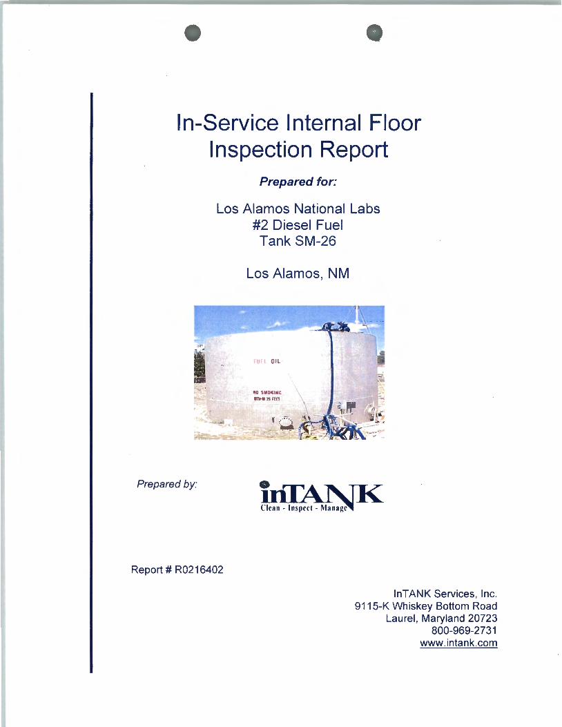
In-Service Internal Floor Inspection Report
Prepared by:
Prepared for:
Los Alamos National Labs #2 Diesel Fuel Tank SM-26
Los Alamos, NM
U l Oil
HO SMO'<IHC lmt«?Srm
Report# R0216402
lnTANK Services, Inc. 9115-K Whiskey Bottom Road
Laurel , Maryland 20723 800-969-2731
www.intank.com
'W Los Alamos National Labs Tank SM-26
In-Service Internal Floor Inspection Report
In-Service Internal Floor Inspection Report
Los Alamos National Labs
Armando Gonzalez
Inspection Dates:
April 29, 2003 to April 30, 2003
It is recommended that this document, containing valuable historical information,
be retained for the lifetime of the tank.
API 653 Aboveground Tank Inspector Certificate# 23988
Proprietary Information 2

""-" Los Alamos National Labs Tank SM-26 In-Service Internal Floor Inspection Report
Table of Contents
1 TANK DESCRIPTION ..................................................................................................................................... 4
2 JOB SUMMARY ................................................................................................................................................ 5
2.1 ULTRASONIC FLOOR THICKNESS RESULTS .................................................................................................. 5 2.2 TANK FLOOR ELEVATION MEASUREMENTS ................................................................................................ 6 2.3 VISUAL INSPECTION ................................................................................................•...•............................... 6
2.3.1 Quik-Look™ Video Results .................................................................................................................... 6
3 CONCLUSION AND RECOMMENDATIONS ............................................................................................. 7
3.1 FLOOR INSPECTION RESULTS ...................................................................................................................... 7
4 UT FLOOR RUNS ............................................................................................................................................. 8
4.1 PLATE THINNING AREAS ............................................................................................................................. 9 4.2 UT RUN DATA FOR CORROSION POINTS ................................................................................................... ! 0 4.3 MINIMUM THICKNESS CALCULATIONS ...................................................................................................... 11
5 ELEVATION DATA ....................................................................................................................................... 12
5.1 CONTOUR MAP .......................................................................................................................................... 12 5.2 SURFACE MAPS ......................................................................................................................................... 13
6 PHOTOGRAPHS ............................................................................................................................................. 17
APPENDIX A- REFERENCE INFORMATION .................................................................................................. 20
A.l FOUR PHASES OF TANK INSPECTION .............................................................................................. 21
A.2 OTIS INSPECTION ................................................................................................................................... 23
A.3 INTERNAL FLOOR INSPECTION EQUIPMENT ............................................................................... 25
A.4 UT RUN DATA ........................................................................................................................................... 26
A.5 XY COORDINATES VEHICLE POSITION TABLE ............................................................................ 28
A.6 OTIS ELEVATION METHODOLOGY ................................................................................................... 30
A.7 REFERENCES ............................................................................................................................................ 32
A.8 WARRANTY ............................................................................................................................................... 33
A.9 INTANK SERVICES, INC. INSPECTION STAFF ................................................................................ 34
Proprietary Information 3

...., Los Alamos National Labs Tank SM-26
In-Service Internal Floor Inspection Report
1 Tank Description
The physical characteristics of Tank SM-26 are summarized below.
GENERAL:
TANK NUMBER:
OWNER: TANK LOCATION:
MANUFACTURER:
PRODUCT:
Table 1-1
Tank Description
SM-26
Los Alamos National Labs Los Alamos, NM
Horton Tank, Chicago Bridge & Iron Co.
#2 Diesel Fuel CATHODIC PROTECTION: No
DATA PLATE PRESENT: Yes
DIMENSIONS: DIAMETER: 35 feet
HEIGHT: 22 feet
GEOMETRY:
FOUNDATION: Concrete Ringwall
BOTTOM: Lap Welded
SHELL: Butt Welded FIXED ROOF: Cone
DATES:
YEAR BUILT: 1950
LAST INSPECTION: 2002,External API 653; *
ACCESS:
FIXED ROOF: Spiral Stairway COATINGS:
BOTTOM: Lined;Type Unknown
SHELL: Silver Paint
FIXED ROOF: Silver Paint
*Previous inspection report was prov1ded to lnTANK Serv1ces, Inc.
Proprietary Information 4
2 Job Summary
....., Los Alamos National Labs Tank SM-26
In-Service Internal Floor Inspection Report
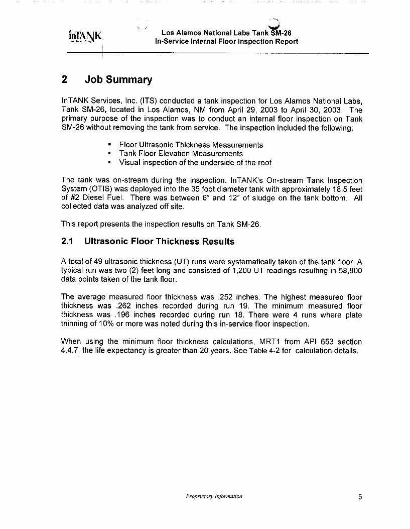
lnTANK Services, Inc. (ITS) conducted a tank inspection for Los Alamos National Labs, Tank SM-26, located in Los Alamos, NM from April 29, 2003 to April 30, 2003. The primary purpose of the inspection was to conduct an internal floor inspection on Tank SM-26 without removing the tank from service. The inspection included the following:
• Floor Ultrasonic Thickness Measurements • Tank Floor Elevation Measurements • Visual inspection of the underside of the roof
The tank was on-stream during the inspection. lnTANK's On-stream Tank Inspection System (OTIS) was deployed into the 35 foot diameter tank with approximately 18.5 feet of #2 Diesel Fuel. There was between 6" and 12" of sludge on the tank bottom. All collected data was analyzed off site.
This report presents the inspection results on Tank SM-26.
2.1 Ultrasonic Floor Thickness Results
A total of 49 ultrasonic thickness (UT) runs were systematically taken of the tank floor. A typical run was two (2) feet long and consisted of 1 ,200 UT readings resulting in 58,800 data points taken of the tank floor.
The average measured floor thickness was .252 inches. The highest measured floor thickness was .262 inches recorded during run 19. The minimum measured floor thickness was .196 inches recorded during run 18. There were 4 runs where plate thinning of 10% or more was noted during this in-service floor inspection.
When using the minimum floor thickness calculations, MRT1 from API 653 section 4.4.7, the life expectancy is greater than 20 years. See Table 4-2 for calculation details.
Proprietary Information 5

...., Los Alamos National Labs Tank SM-26
In-Service Internal Floor Inspection Report
2.2 Tank Floor Elevation Measurements
Tank floor elevation variations were calculated using the elevation data gathered during this in-service inspection. The data consisted of 53 runs, 49 of which were UT runs and four (4) runs of additional elevation data. The maximum measured depth change has suggested that the floor is out of level by approximately 1 .4 inches. See Section 5 for visual representation of the elevation profile.
The elevation runs taken did not reveal excessive deviation. Bottom settlement was within acceptable limits according to API 653 Appendix B (Evaluation of tank bottom).
2.3 Visual Inspection
2.3.1 Quik-Look™ Video Results
The fixed roof underside plates and joints appear to be in acceptable condition. No mechanical damage or distortion is evident in the video.
Initial stages of corrosion seem to be developing in areas of the fixed roof underside plates, shell walls, and roof rafters. Consideration should be given to cleaning and coating these areas at the next opportunity.
The central column support and the joint areas between roof rafters and shell walls appear to be in satisfactory condition.
The vapor space of the tank appears to be in acceptable condition.
Proprietary Jriformation 6

..., Los Alamos National Labs Tank SM-26
In-Service Internal Floor Inspection Report
3 Conclusion and Recommendations
3.1 Floor Inspection Results
Rummel, Klepper and Kahl, LLP Consulting Engineers has reviewed all the data provided in the In-Service Internal Floor Inspection Report prepared by lnTank, Inc. for the Los Alamos National Labs #2 Diesel Fuel Tank SM-26 in Los Alamos, NM. The engineering review included checking all the provided data and calculations and ensuring their compliance with applicable standards.
Based on the data provided from the internal inspections no tank floor integrity issues were detected. Over the fifty-three (53) years that the tank has been in service it has experienced a 0.001 0-inch per year corrosion rate. Approximately 8% of the floor ultrasonic thickness runs indicated bottomside corrosion. The most severe of the pitting areas has experienced a 21.6% metal loss.
Using the minimum remaining thickness (MRT) calculations from API 653 4.4.7.1 the tank floor has an estimated life in excess of twenty (20) years. Based on the calculated corrosion rate for the tank floor and in accordance with API Standard 653 paragraph 6.4.2, the next internal floor inspection should not exceed twenty (20) years. It is also recommended that monthly inspections and five (5) year external inspections be conducted as recommended in API 653.
The Quik-Look™ camera system identified some areas in the fixed roof underside plates, shell walls, and roof rafters that show the initial stages of localized internal corrosion. Based on the results of the internal inspection we recommend an internal inspection of these areas the next time the tank is out of service.
Proprietary Information 7

4 UT Floor Runs
Los Alamos National Labs Tank ~-26 In-Service Internal Floor Inspection Report
The following shows the UT run distributions taken during the in-service inspection.
20" Vertical Manway
4" Supply
4" Return
Varec Gauge Stairs Roof Manway
Figure 4-1
Distribution of All UT Runs
2" Draw With Sump
Note: Numeric values represent run numbers. Each run is approximately 2 feet long. The grid represented above is in 5.14 foot increments. See Table A.S-1.
Proprietary Information 8

...., Los Alamos National Labs Tank SM-26
In-Service Internal Floor Inspection Report
4.1 Plate Thinning Areas
The following shows the UT runs where plate loss was at least 10% less than design.
20" Vertical Manway
4" Supply
4" Return
Varec Gauge
2" Draw With Sump
Stairs Roof Manway
Figure 4-2
Distribution of Plate Thinning Areas Greater than 10% of Nominal Plate Thickness
Note: Numeric values represent run numbers. Each run is approximately 2 feet long. The grid represented above is in 5.14 foot increments.
Proprietary Information 9
Run#
17 18 28 3 1
Los Alamos National Labs Tank SM-26 In-Service Internal Floor Inspection Report
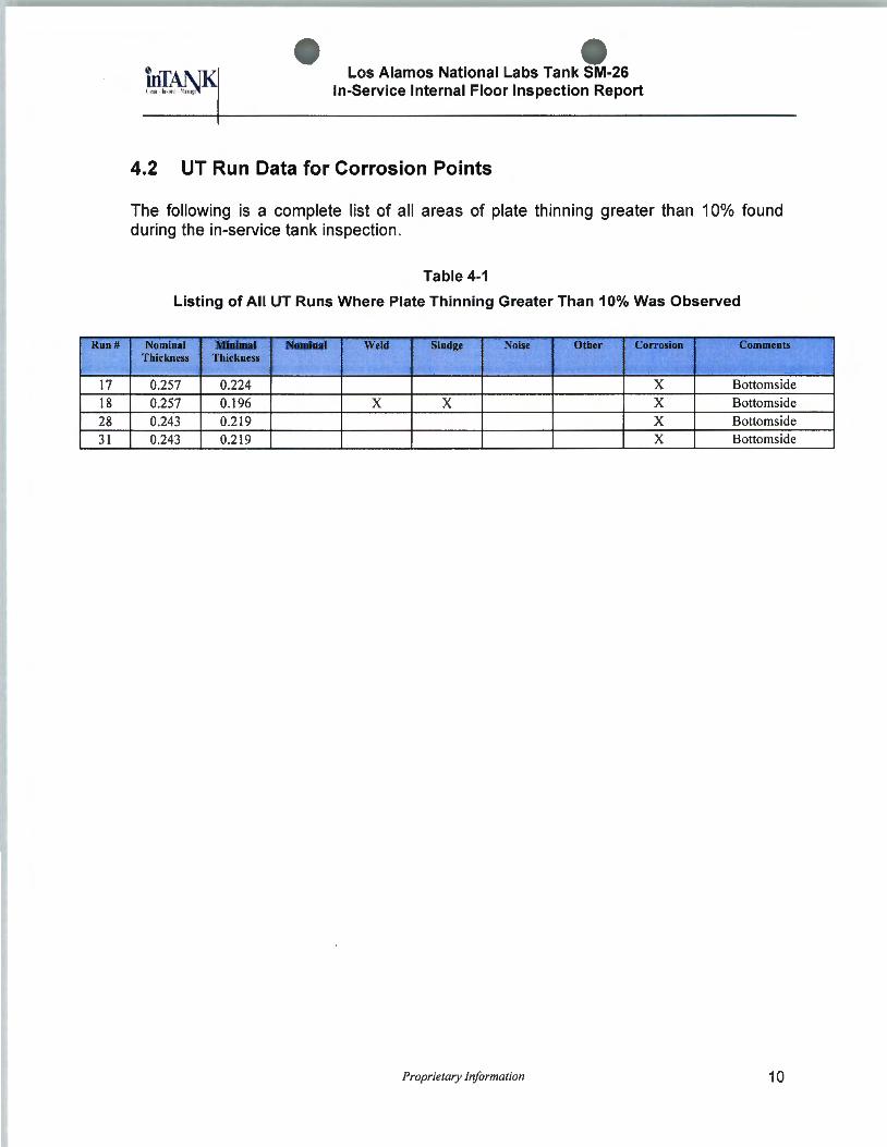
4.2 UT Run Data for Corrosion Points
The following is a complete list of all areas of plate thinning greater than 10% found during the in-service tank inspection .
Table 4-1
Listing of All UT Runs Where Plate Thinning Greater Than 10% Was Observed
Nominal Minimal Nominal Weld Sludge Noise Other Corrosiou Commeuts Thickness Thickness
0.257 0.224 X Bottoms ide 0.257 0.196 X X X Bottomside 0.243 0.2 19 X Bottomside 0.243 0.2 19 X Bottoms ide
Proprietary Information 10

Los Alamos National Labs Tank SM-26 In-Service Internal Floor Inspection Report
4.3 Minimum Thickness Calculations
The following provides a summary of the tank bottom life expectations based on the results of the in-service UT inspection.
Table 4-2
Minimum Remaining Thickness Table
Course Material:
In-service Date: Last Inspected Date (LID)
Full Repairs After LID? To: Design Nominal
(inches):
Average Nominal (inches):
Internal Lining?
StPa: Average Depth of Internal Pitting
UPa: Average Depth of Underside Pitting
StPr: Maximum internal pitting rate per year
RTip: Minimum Floor Thickness considering topside corrosion only.
Or: Per API 653 4.4.7.1
Or1: Maximum Underside/Average Topside
MRT Calculation: *Or:
Carbon Steel
1950 Unknown
No 0.250
0.252
Yes
0.000
0.036
0.0000
0.2500
>20 years
>20 years
-(MRT- (Minimum of RTbc or RTip))/(StPr+UPr)
* OR1 : -(MRT1 -To+StPa+Upm)/(StPr+Upr)
* OR2: -(MRT2-To+StPm+Upa)/(StP2+Upr)
Number of Readings:
In-service Years: Years Since Last Brought to Design
Nominal:
MRT 1: Minimum Remaining Thickness
MRT 2: Minimum Remaining Thickness
Cathodic Protection?
StPm: Maximum Depth of Internal Pitting
UPm: Maximum Depth Underside Pitting
UPr: Maximum underside pitting rate per year
RTbc: Minimum Floor Thickness considering bottomside corrosion only.
Or2: Maximum Topside/Average Underside
Proprietary Information
58,800
53 53
0.050
0.050
No
0.000
0.054
0.0010
0.1960
>20 years
11

5 Elevation Data
5.1 Contour Map
Los Alamos National Labs Tank SM-26 In-Service Internal Floor Inspection Report
The following is a contour map of the tank bottom floor that was generated during the internal floor inspection .
20
15
10
.... Qi) 5 Qi)
u.. c ... Q) 0 -Q)
E (Q
Q .5
-10
-15
-20
-20 -15 -10 0 5
Diameter in Feet
Figure 5-1
Elevation Data
10
·, ~
~ . N
Scale in Inches
15 20
Note: Scale is noted in feet for the diameter of the tank and in inches for the noted depth change.
Proprietary Information 12
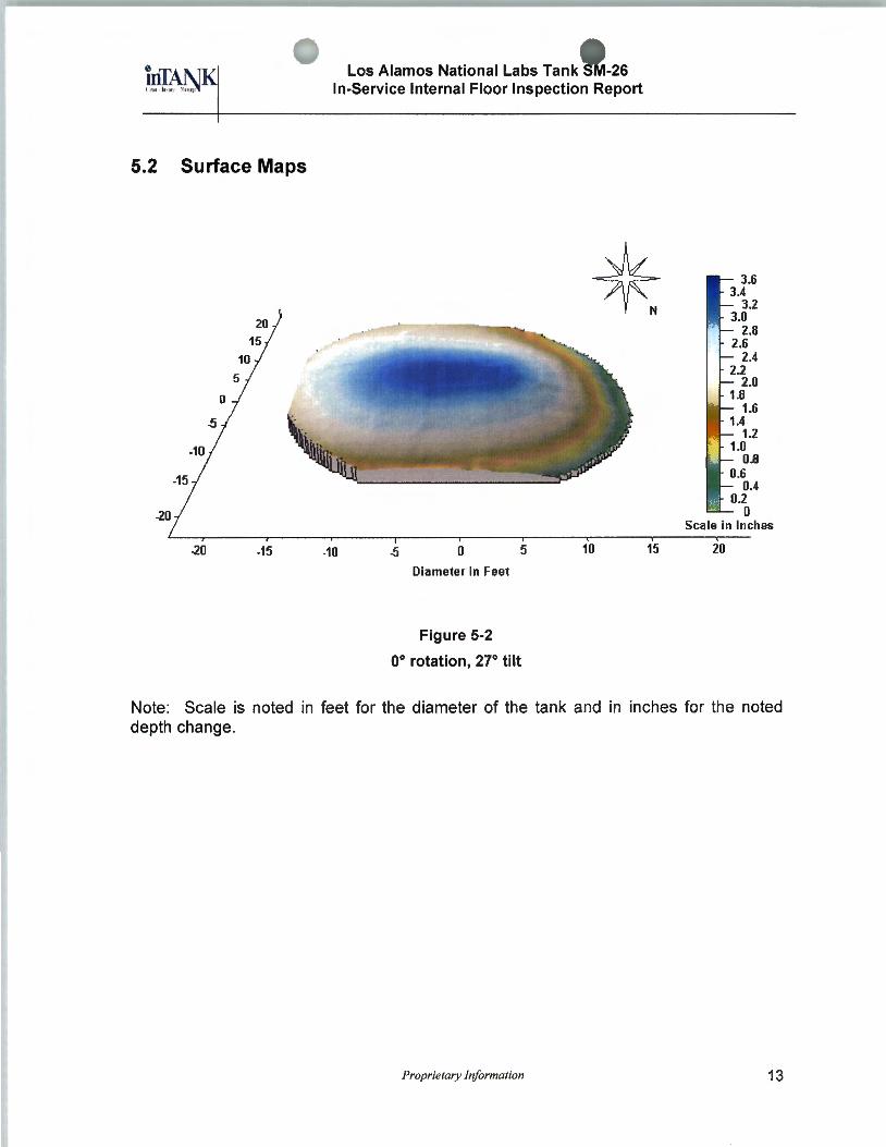
5.2 Surface Maps
-20 -15
Los Alamos National Labs Tank S -26 In-Service Internal Floor Inspection Report
-10 0 5 10
Diameter in Feet
Figure 5-2
0° rotation, 27° tilt
15 20
Note: Scale is noted in feet for the diameter of the tank and in inches for the noted depth change.
Proprietary Information 13

-20
-20 -15
Los Alamos National Labs Tank SM-26 In-Service Internal Floor Inspection Report
-10 0 5 10 15
Diameter in Feet
Figure 5-3
90° rotation, 27° tilt
Scale in Inches
20
Note: Scale is noted in feet for the diameter of the tank and in inches for the noted depth change.
Proprietary Information 14

0
-20 -15
Los Alamos National Labs Tank S -26 In-Service Internal Floor Inspection Report
-10 0 5 10
Diameter in Feet
Figure 5-4
180° rotation, 27° tilt
Scale in Inches
15 20
Note: Scale is noted in feet for the diameter of the tank and in inches for the noted depth change.
Proprietary Information 15
0
-1111
-15
-20
-20 -15
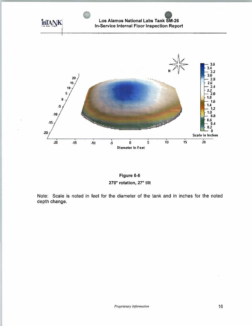
Los Alamos National Labs Tank SM-26 In-Service Internal Floor Inspection Report
-10 0 Diameter in Feet
Figure 5-5
5
270° rotation, 27° tilt
10
Scale in Inches
15 20
Note: Scale is noted in feet for the diameter of the tank and in inches for the noted depth change.
Proprietary Information 16

6 Photographs
Los Alamos National Labs Tank S'M-26 In-Service Internal Floor Inspection Report
FUEL OIL
flO S~lO~IHC ·
zsrrrr
Tank
Foundation
Proprietary Information 17

Los Alamos National Labs Tank -26 In-Service Internal Floor Inspection Report
Varec Gauge
Spiral Stairway
Proprietary Information 18

Los Alamos National Labs TankS -26 In-Service Internal Floor Inspection Report
Roof
Data Plate
Proprietary Information 19
Los Alamos National Labs Tank~-26 In-Service Internal Floor Inspection Report
Appendix A- Reference Information
Proprietary Information 20
~ ~ ~ ,, Los Alamos National Labs Tank ~-26
In-Service Internal Floor Inspection Report
A.1 Four Phases of Tank Inspection
There were four major phases to the OTIS inspection process. These phases include plant briefing and safety training, initial system rig-up, scanning operations, and rigdown. The following events occurred within each phase.
1. Plant/Terminal Briefing:
a. An introduction to the OTIS inspection process was presented to the customer.
b. ITS personnel completed required safety training. c. Equipment safety review was completed.
2. Rig-Up:
a. The OTIS truck arrived on site. b. Safety tape and cones were set up around the work site. c. OTIS gear was prepared for crane lift. d. OTIS operators in the van prepared the OTIS software and input the required
tank dimensions into the display system. e. Outside of the tank, the OTIS technicians installed temporary magnetic
transducers used for OTIS navigation to the side of the tank. f. OTIS personnel on top of the tank removed the top man way and prepared
OTIS for entrance into the tank.
3. Scanning Operations:
a. The operator drove the OTIS machine across the tank bottom along a predefined path.
b. The pre-defined path consisted of multiple 2-foot "runs." The number of runs made depended on the amount of data that the tank owner wanted to acquire.
c. In all cases, sufficient data was taken to satisfy API 653 requirements. d. OTIS collected 1,200 ultrasonic samples for each data run. e. Ultrasonic data was acquired every 0.16 inch during each run. f. All data was reviewed and analyzed off site.
Proprietary Information 21
Los Alamos National Labs Tank ~-26 In-Service Internal Floor Inspection Report
4. Rig-Down Operations:
a. During the initial data analysis process in the OTIS van, rig-down operations began.
b. The OTIS vehicle was removed from the tank and the umbilical stored into its container.
c. The navigation transducers were removed from the tank walls. d. Two crane lifts removing the equipment from the top of the tank to the ground
were required. e. All cabling and instrumentation was stored into the OTIS van.
Proprietary Information 22
Los Alamos National Labs Tank S -26 In-Service Internal Floor Inspection Report
A.2 OTIS Inspection
The tank floor inspection was conducted with a remotely controlled machine. The primary objective of OTIS was to inspect aboveground storage tanks while they are inservice. The only tank access required by OTIS was a roof man-way. No modifications were necessary. The fluids may be transferred to and from the tank while the inspection takes place. OTIS inspection and Quik-Look™ methodology and UT readings adhere to API 653 guidelines.
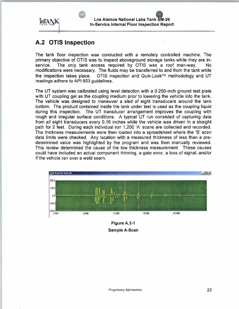
The UT system was calibrated using level detection with a 0.250-inch ground test plate with UT coupling gel as the coupling medium prior to lowering the vehicle into the tank. The vehicle was designed to maneuver a sled of eight transducers around the tank bottom. The product contained inside the tank under test is used as the coupling liquid during this inspection. The UT transducer arrangement improves the coupling with rough and irregular surface conditions. A typical UT run consisted of capturing data from all eight transducers every 0.16 inches while the vehicle was driven in a straight path for 2 feet. During each individual run 1,200 'A' scans are collected and recorded . The thickness measurements were then loaded into a spreadsheet where the 'B' scan data limits were checked. Any location with a measured thickness of less than a predetermined value was highlighted by the program and was then manually reviewed . This review determined the cause of the low thickness measurement. These causes could have included an actual component thinning , a gate error, a loss of signal , and/or if the vehicle ran over a weld seam.
250.0
125.0
0.0
-125.0
-250.0 0.000 6.000 12.000
Figure A.2-1
Sample A-Scan
Proprietary Information
- Cl ~
18.000 24.000
23

Los Alamos National Labs Tank SM-26 In-Service Internal Floor Inspection Report
!::3 8 Stan Samples I to ISO (Seletted Sample -64 oll5l).IIB·Scan extends beyond white area, click on white ar
•• II I& ;ga 4 MilA ~~ r 8 141fih12EF&l S m&&l &£) 4 'tfi! ill:;;;:;;;;; AP#GlhMh£ 6 Q
·••'----------------------------------'
•• ~iiiiiiiiiiiiiiiiiiiiiiiiiiiiiiiiiiiiiiiiiiiiiiiiiiiiiiiiiiiiiiiiii"iiiiiiiiiiiiiiiiiiiiiiiiij ~· .... ~· ~· .,.L___ _ _ ________________________ ___,
~.·.~:~ rmv ., I : L A pgpp;g;; Iii &ii&&l .
··~iiiiii .. iiinii~miiiiiiini~~~iiiiiiiiiBiBBiBi~--~ ~L....r ____ *_lillii_'*_•_MM_ M&Ma ____ '_*_w_"'_:AQMN ___ , _._~_• _______ &&_aaaa _ ___,l 0.000 4.BOO 9.BOO 14 .400
Figure A.2-2
Sample B-Scan
19.200 24 .000
UT readings were taken based on a grid pattern overlaid onto a computer-aided design drawing of the tank. The drawing was generated after actual measurements are made of the tank circumference and the location of appurtenances including the roof manway. The number of UT readings taken depends on the requirements of the tank owner, the size of the tank and the condition of the tank.
In Figure A.2-1 , the example of an A Scan shows the front and rear walls from which manual spatial measurements were derived. A shift of the first A-Scan returns or the lack of a shift used to determine the presence of topside or bottom-side corrosion.
At the conclusion of the tank inspection , a map of the tank floor was generated indicating the location of pitting and/or corrosion . Some estimation of the amount of sludge in the tank was provided as well.
Proprietary Information 24
Los Alamos National Labs Tank S'"M-26 In-Service Internal Floor Inspection Report
A.3 Internal Floor Inspection Equipment
OTIS was designed to inspect the bottoms of aboveground storage tanks to meet API and regulatory tank inspection requirements without the need for removing the tank from service and without personnel entry. The remotely controlled system was composed of a sludge removal vacuum system, a robotic vehicle with an in-tank navigation system, an eight-transducer array ultrasonic system and a video system. The vehicle was designed to operate in both fixed and floating roof storage tanks, and can be deployed through a 20-inch man-way.
When deployed inside of the tank, the robot simultaneously vacuumed sludge and performed an ultrasonic inspection of the tank floor. The position and orientation of the vehicle were determined in real-time using onboard and tank external shell-mounted navigation transducers, which enabled the vehicle to be mapped on a display of the tank floor plates. Position resolution was on the order of a few inches. During the inspection, the vehicle location for each bottom plate thickness measurement was recorded along with the ultrasonic returns from the tank floor. Though some data evaluation was conducted while the vehicle was in the tank, the majority of the data analysis was conducted post-test. In addition to the thickness map of the floor, the UT data analysis software allows for the identification of bottom-side and topside corrosion. The vehicle was also capable of detecting tank bottom settlement with onboard pressure transducers. The system was deployed with the tank full of product.
Deployment operations consisted of locating the equipment van and associated utilities adjacent to the tank outside the berm area. The deployment process required three crane lifts to the top of the tank. Equipment located at the top of the tank included the submersible vehicle and umbilical, pumping systems and in-tank deployment gear. A 350-foot umbilical was used to support vehicle operations.
The OTIS approach can be used to satisfy a number of objectives, from general integrity testing to in-service API 653 inspections. OTIS methodology responds to the American Petroleum Institute 653 alternative internal inspection approaches to determine bottom corrosion rates.
Proprietary Information 25

A.4 UT Run Data
Los Alamos National Labs Tank SM-26 In-Service Internal Floor Inspection Report
The following table is a complete list of all UT run areas taken during the in-service tank inspection. Each run is approximately two (2) feet long
Table A.4-1
UT Data for All UT Runs
Run# Nominal Minimal Nominal Weld Sludge Noise Other Corrosion Comments Thickness Thickness
1 0.248 0.233 X 2 0.252 0.242 X 3 0.257 0.247 X X 4 0.257 0.247 X 5 0.252 0.238 X X 6 0.243 0.233 X 7 0.248 0.233 X 8 0.252 0.238 X 9 0.248 0.233 X 10 0.257 0.252 X II 0.257 0.247 X 12 0.248 0.238 X 13 0.257 0.238 X 14 0.257 0.238 X 15 0.252 0.233 X 16 0.257 0.247 X X 17 0.257 0.224 X Bottomside 18 0.257 0.196 X X X Bottomside 19 0.262 0.256 X 20 0.257 0.252 X 21 0.257 0.233 X 22 0.248 0.242 X 23 0.248 0.237 X 24 0.248 0.237 X 25 0.257 0.247 X 26 0.243 0.237 X X 27 0.248 0.237 X X 28 0.243 0.219 X Bottoms ide 29 0.252 0.242 X 30 0.252 0.247 X 31 0.243 0.219 X Bottoms ide 32 0.257 0.247 X 33 0.252 0.242 X
Proprietary information 26
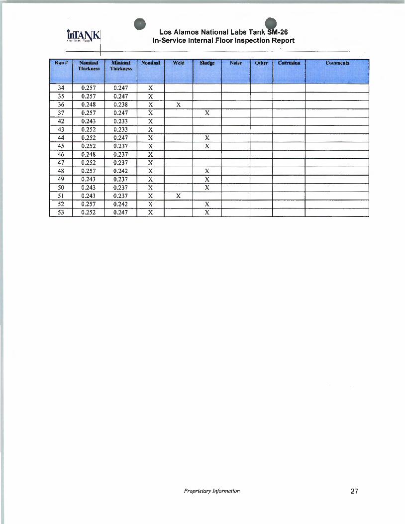
Run# Nominal Minimal Thickness Thickness
34 0.257 0.247 35 0.257 0.247 36 0.248 0.238 37 0.257 0.247 42 0.243 0.233 43 0.252 0.233 44 0.252 0.247 45 0.252 0.237 46 0.248 0.237 47 0.252 0.237 48 0.257 0.242 49 0.243 0.237 50 0.243 0.237 51 0.243 0.237 52 0.257 0.242 53 0.252 0.247
Los Alamos National Labs Tank S -26 In-Service Internal Floor Inspection Report
Nominal Weld Sludge Noise Other Corrosion
X X X X X X X X X X X X X X X X X X X X X X X X X X
Proprietary Information
Comments
27

Los Alamos National Labs Tank · -26 In-Service Internal Floor Inspection Report
A.5 XY Coordinates Vehicle Position Table
The following represents the x,y coordinates of the OTIS vehicle during data collection. The tank grid represented is in 5.14 foot increments. The x,y coordinates 0,0 represent the center of the tank. The Start x,y coordinates indicate the vehicles starting position and the End x,y coordinates indicate the vehicles stopping position of each run . This table allows the tank owner and future inspectors the capability to evaluate specific areas of concern in the future.
Table A.5-1 XY Coordinate Data for All UT Runs
Run X Start YStart X End VEnd (feet) (feet) (feet) (feet)
1 -6.329 7.063 -6.347 6.135 2 -8.114 -1 0.042 -8.043 -9.326 3 -7.815 -7.289 -7.778 -6.686 4 -5.227 -4.065 -7.309 -3.050 5 -6.856 0.542 -6.794 1.368 6 -6.483 5.390 -6.456 6.292 7 -6.384 8.291 -6.366 8.336 8 -3.960 -11 .720 -3.900 -11 .114 9 -3.553 -8.371 -3.397 -7.466 10 -3.362 -4.218 -3.425 -3.416 11 -3.548 0.754 -3.552 1.459 12 -3.890 5.605 -3.742 6.551 13 -11 .915 -6.979 -12.209 -6.128 14 -13.696 -2.008 -13.986 -1 .247 15 -13.920 0.990 -14.094 2.053 16 -8.331 -13.971 -9.174 -13.494 17 -11 .238 -11 .921 -12.020 -11 .196 18 -14.013 -8.419 -14.493 -7.565 19 -15.124 -5.867 -15.631 -5.023 20 -16.139 -2.683 -16.030 -2.511
21 -16.309 1.024 -16.121 1.620 22 2.785 -11 .687 2.801 -10.991
23 3.607 -8.326 3.923 -7.467
24 4.100 -4.294 4.074 -3.544 25 4.131 0.790 4.115 1.699 26 3.996 5.890 4.035 6.427
27 6.971 -11 .087 7.060 -10.304
28 7.721 -4.321 7.755 -3.691
29 8.023 0.938 8.075 1.632
30 8.293 5.116 8.307 5.948 31 11 .358 -8.197 11 .659 -7.414
32 11 .210 -4.210 11 .126 -3.441
33 11.482 1.294 11 .639 2.006
Proprietary Information 28

Run X Start (feet)
34 8.844 35 12.674 36 15.629 37 17.189 38 2.468 39 1.530 40 -3.516 41 -1 .175 42 -1 .919 43 -6.488 44 -11 .188 45 -11 .505 46 -2.959 47 7.625 48 7.725 49 4.812 50 2.603 51 2.757 52 12.133 53 12.258
Los Alamos National Labs Tank SM-26 In-Service Internal Floor Inspection Report
YStart X End (feet) (feet)
-15.071 9.820 -12.824 12.703 -7.177 16.100 -3.485 16.883 -2.635 15.971 -2.277 -0.679 0.098 -15.332 5.007 -2.633 10.467 -2.043 10.227 -6.505 6.040 -11.444 10.968 -10.986 14.430 -3.068 6.061 7.583 10.475 7.754 9.010 4.418 12.573 2.983 12.275 2.441 5.016 12.556
10.355 11.975
Proprietary Information
VEnd (feet)
-14.480 -11.982 -6.269 -4.568 3.022
-16.511 4.135 14.772 11 .182 10.860 6.678 11 .528 15.108 6.706 11 .238 9.757
11 .829 12.987 5.762 10.621
29
Los Alamos National Labs Tank SM-26 In-Service Internal Floor Inspection Report
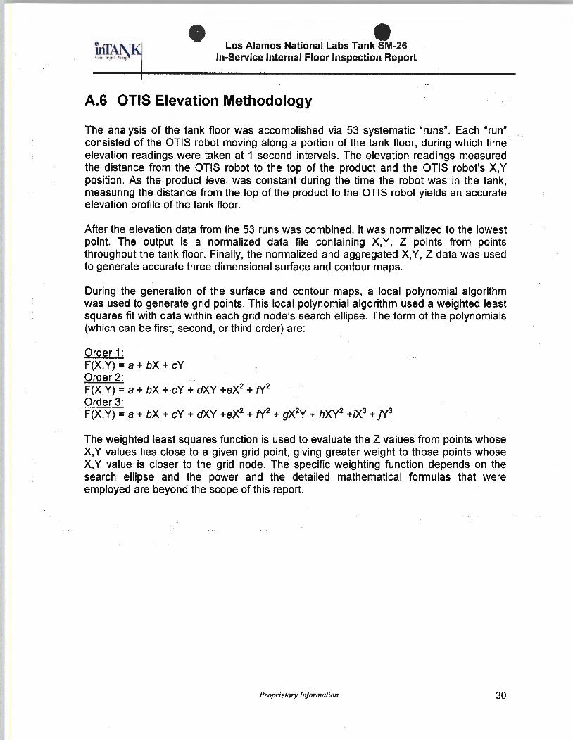
A.6 OTIS Elevation Methodology
The analysis of the tank floor was accomplished via 53 systematic "runs". Each "run" consisted of the OTIS robot moving along a portion of the tank floor, during which time elevation readings were taken at 1 second intervals. The elevation readings measured the distance from the OTIS robot to the top of the product and the OTIS robot's X,Y position. As the product level was constant during the time the robot was in the tank, measuring the distance from the top of the product to the OTIS robot yields an accurate elevation profile of the tank floor.
After the elevation data from the 53 runs was combined , it was normalized to the lowest point. The output is a normalized data file containing X,Y, Z points from points throughout the tank floor. Finally, the normalized and aggregated X,Y, Z data was used to generate accurate three dimensional surface and contour maps.
During the generation of the surface and contour maps, a local polynomial algorithm was used to generate grid points. This local polynomial algorithm used a weighted least squares fit with data within each grid node's search ellipse. The form of the polynomials (which can be first, second, or third order) are:
Order 1: F(X,Y) =a+ bX + cY Order 2: F(X,Y) =a+ bX + cY + dXY +eX2 + fY2
Order 3: F(X,Y) =a+ bX + cY + dXY +eX2 + fY2 + gX2Y + hXY2 +tX3 + JY3
The weighted least squares function is used to evaluate the Z values from points whose X,Y values lies close to a given grid point, giving greater weight to those points whose X,Y value is closer to the grid node. The specific weighting function depends on the search ellipse and the power and the detailed mathematical formulas that were employed are beyond the scope of this report.
Proprietary Information 30

Los Alamos National Labs Tank M-26 In-Service Internal Floor Inspection Report
The following table shows the minimum and maximum normalized height for each of the 53 runs taken.
Table A.G-1
Minimum and Maximum Normalized Height
Run Min Max Run Min Max 1 2.472 2.728 38 0.487 3.435 2 2.265 2.460 39 0.645 3.276 3 2.813 2.923 40 2.436 3.654 4 3.313 3.386 41 1.279 2.777 5 2.996 3.094 42 1.827 1.924 6 2.631 2.801 43 1.754 1.937 7 2.314 2.448 44 2.180 2.412 8 2.034 2.144 45 1.705 1.803 9 2.533 2.826 46 1.669 1.778 10 3.276 3.398 47 1.815 1.961 11 3.240 3.361 48 1.364 1.559 12 2.679 2.826 49 1.778 1.973 13 2.229 2.436 50 1.535 1.596 14 2.277 2.448 51 1.462 1.583 15 2.509 2.570 52 1.194 1.328 16 1.145 1.340 53 0.512 0.597 17 1.535 1.754 18 1.559 1.839 19 1.754 1.875 20 1.620 1.668 21 1.827 1.949 22 1.668 1.863 23 2.436 2.643 24 3.179 3.361 25 3.496 3.581 26 2.533 2.704 27 1.547 1.668 28 2.753 2.874 29 2.655 2.777 30 1.985 2.229 31 1.340 1.425 32 1.839 2.095 33 1.693 1.863 34 0.292 0.402 35 0.414 0.475 36 0.012 0.158 37 0.000 0.158
Proprietary Information 31

A. 7 References
Los Alamos National Labs Tank SM-26 In-Service Internal Floor Inspection Report
American Petroleum Institute:
API Standard 650, Welded Steel Tanks for Oil Storage.
API Recommended Practice 651, Cathodic Protection of Aboveground Petroleum Storage Tanks.
API Standard 653, Tank Inspection. Repair. Alteration. and Reconstruction .
American Society of Mechanical Engineers Codes:
ASME Boiler and Pressure Vessel Code; Section V, Non Destructive Examination .
ASME Boiler and Pressure Vessel Code; Section IX, Welding and Brazing Qualifications.
Code of Federal Regulations:
29 CFR 1910, Permit-Required Confined Spaces for General Industry.
National Association of Corrosion Engineers:
NACE Recommended Practice, RP0184-91 , Repair of Lining Systems.
NACE Recommended Practice, RP0193-93, External Cathodic Protection of OnGrade Metallic Storage Tank Bottoms.
NACE Recommended Practice, RP0288-94, Inspection of Linings on Steel and Concrete.
National Fire Protection Association:
NFPA-30, Flammable and Combustible Liquids Code
Proprietary Information 32

A.8 Warranty
Los Alamos National Labs Tank SM-26 In-Service Internal Floor Inspection Report
While our evaluation accurately describes the condition of the tank at the time of inspection, the tank owner/operator must independently assess the inspection information/report provided by lnTANK Services, Inc. Any conclusions reached by the tank owner/operator and any action taken or omitted to be taken are the sole responsibility of the owner/operator. With respect to inspection and testing, lnTANK Services, Inc. warrants only that the services have been performed in accordance with accepted industry practice. If any such services fail to meet the foregoing warranty, lnTANK Services, Inc. shall re-perform the service to the same extent and on the same conditions as the original service.
The preceding paragraph sets forth the exclusive remedy for claims based on failure or of defect in materials or services, whether such claim is made in contract or tort (including negligence) and however instituted , and, upon expiration of the warranty period, all such liability shall terminate. The foregoing warranty is exclusive and in lieu of all other warranties, whether written , oral , implied or statutory. NO IMPLIED WARRANTY OF MERCHANTABILITY OR FITNESS FOR PURPOSE SHALL APPLY, nor shall lnTANK Services, Inc. be liable for any loss or damage whatsoever by reason of its failure to discover, report, repair or modify latent defects or defects inherent in the design of any tank inspected . In no event, whether a result of breach of contract, warranty or tort (including negligence) shall lnTANK Services, Inc. be liable for any consequential or incidental damages including , but not limited to , loss of profit or revenues, loss of use of equipment tested or services by lnTANK Services, Inc. or any associated damage to facilities , down-time costs or claims of other damages.
Proprietary Information 33

Los Alamos National Labs Tank M-26 In-Service Internal Floor Inspection Report
A.9 lnTANK Services, Inc. Inspection Staff
The following people were involved , in part or whole, during internal inspection and report generation.
Person Gary Buck
Gerrald Stennett
Rob McGinn
Jim Brady
Title Project Manager
Ultrasonic Data Collector
Vehicle Operator
UT Data Analyst
Proprietary information 34