Embed Size (px)
Citation preview
3/29/2018
Alabama Minimum Specifications
for School Buses
Alabama State Department of Education
Division of Administrative and Financial Services
Pupil Transportation Section
Montgomery, Alabama 334-242-9730
Ed Richardson - Interim
State Superintendent of Education
Chad Carpenter
Program Administrator
Pupil Transportation
The Alabama Minimum Specifications for School Buses can be found on the Alabama State Department
of Education website at www.alsde.edu under Department Offices/Division of Policy and Budget/Office
of Supporting Programs/Pupil Transportation/Publications.
2019
Effective Date: April 1, 2018

3/29/2018
Alabama Minimum Specifications for School Buses
Changes Document
New requirements and changes in the Alabama Minimum Specifications for School Buses for 2018 are found on the following pages and headings. All changes appear in bold italics with the
exception of deletions. For noted deletions refer to the 2018 specifications for comparison.
NOTE: Page numbers in 2018 specifications and 2019 specifications may not coincide
Page Section General Description of Change
2 New Technology No Supervisor should allow any aftermarket item that is not already approved on an Alabama School Bus to be installed
without consulting ALSDE. 5 Brakes All buses shall either have a parking pawl in the transmission or
a brake interlock that requires the service brake to be applied to allow release of the parking brake.
17 Child Check System New Requirement
22 Additional Emergency Exits Removed “In the following vehicles” added, “based on the maximum designed capacity”.
26 Identification Soundoff 7500 Driver Alert Sign.
28 Lamps and Signals Any light not integrated with the Manufacturer’s headlamp assembly shall be L.E.D.
29 Lamps and Signals Changed “shall” to “may”.
37 Trash Container and Holding Device
“Shall be required” and “The trash container shall”.
43 Special Needs General Requirements
Added sections a, b, and c. to section 3.
55 Alternative Fuel Standards Removed Gasoline from list.
59 Guidelines for Pre School Addition of Guideline for the SAFE Transportation of Pre-School Age Children in School Buses.

Specifications Committee 2018
INTRODUCTION
Alabama law (32-5-8) requires the Alabama State Board of Education to adopt minimum standards to
govern the specifications for all new school buses and the overall operation of all school buses in the state of Alabama. This responsibility also extends to the inspection of school buses being sold and operated in the state of Alabama. The primary reason for the development of specifications and the inspection of school buses is to enhance the safety of Alabama’s school buses. Every effort must be made to ensure
that Alabama school buses continue to provide the safest transportation available for our most precious cargo—our students. On behalf of the Alabama State Department of Education (ALSDE), I want to express great appreciation
to each member of the Alabama School Bus Specifications Committee for their service, hard work, and commitment to the task. Special thanks are also extended to Specifications Committee Chairperson, Jeff Duke. His many years of experience, leadership, and dedication helped to ensure a successful committee meeting resulted in another set exceptional specifications.
Special thanks must also be expressed to Alabama's school bus dealers, their school bus manufacturers and the many vendors and others in the school bus industry that assisted in the development of these standards. Without their participation, the specifications process would be significantly weakened.
School bus specifications always begin as a product of many individual thoughts and ideas. However, they culminate in standards, which help assure the safest school buses possible as well as vehicles, which provide a true value for Alabama's taxpayers.
The Alabama Minimum Specifications for School Buses become effective on April 1, 2018. If you have questions or recommendations regarding any of the specifications in this document, please contact Mr. Jeff Duke at the ALSDE or any member of the specifications committee. Committee members are listed
on the page after the Mission Statement.
Chad Carpenter, Program Administrator
Pupil Transportation Alabama State Department of Education
Montgomery, Alabama 36130 334-242-9730

Specifications Committee 2018
MISSION STATEMENT
The mission of the Alabama State Department of Education (ALSDE), Pupil Transportation Department is to ensure safe transportation for the children of Alabama.
Concerning the competitive bidding of school buses, the ALSDE supports the Code of Alabama, 16-13B-1, as cited below as a guideline for local Boards of Education to purchase safe school buses at an affordable price. “School buses” shall be classified in the category “materials, equipment, supplies” and should only include components which are tangible.
The Code of Alabama
Section 16-13B-1
COMPETITIVE BIDDING FOR CERTAIN CONTRACTS OF COUNTY AND CITY BOARDS OF EDUCATION
Applicability; local preference zone; joint agreement; bid bond.
(a) This chapter shall apply to county boards of education and city boards of education, or any
combination of city and county boards of education as herein provided for the competitive bidding of certain contracts. With the exception of contracts for public works whose competitive bidding requirements are governed exclusively by Title 39, all expenditure of funds of whatever nature for labor, services, work, or for the purchase of materials, equipment, supplies, or other personal property involving
fifteen thousand dollars ($15,000) or more, and the lease of materials, equipment, supplies, or other personal property where the lessee is, or becomes legally and contractually, bound under the terms of the lease, to pay a total amount of fifteen thousand dollars ($15,000) or more, made by or on behalf of any city or county board of education, except as hereinafter provided, shall be made under contractual
agreement entered into by free and open competitive bidding, on sealed bids, to the lowest responsible bidder. (Text bolded or underlined for emphasis; not in the original)

Specifications Committee 2018
Alabama State Department of Education (ALSDE) School Bus Specifications Committee
January 1, 2018
Kenneth Allen
Lee County Schools
614 Magazine Avenue Opelika, AL 36801
334-745-4351
Joe Avilez
[email protected] Baldwin County Schools
2600-A Hand Avenue
Bay Minette, AL 36507
251-580-1894
Jackilyn Barefield
Ozark City Schools
860 N. US Highway 231
Ozark, AL 36360
334-774-5197
Kevin Brooks
Cleburne County Schools
93 Education Street Heflin, AL 36264
256-463-2457
Josh Dunn
[email protected] Jefferson County Schools
2513 Cedar Hill Drive
Birmingham, AL 35217
205-379-4605
Henry Hampton [email protected]
Athens City Schools
1300 Armory Street
Athens, Alabama 35613
256-233-6637
Claude Massey [email protected]
Trussville City Schools
113 N. Chalkville Road Trussville, Alabama 35173
205-228-3002
Neil Messick
Autauga County Schools 153 W. 4th Street Prattville, Alabama 36067
334-361-3897
Jeff Nichols
[email protected] Alabaster City Schools
1953 Municipal Way, Suite 200
Alabaster, Alabama 35007
205-288-2199
Hank Summerford
Morgan County Schools
375 East Cave Springs Rd.
Decatur AL. 35603 256-309-2135
Jerry Jones
Tuscaloosa County Schools
3700 68th Avenue Northport, Alabama 35473
205-342-2636
Shea White
[email protected] Pell City Schools
1000 Bruce Etheredge
Pell City, Alabama 35128
205-884-4800
Chad Carpenter
Administrator
State Department of Education 334-850-1812
Jerome Cook
State Department of Education 251-581-0236
Jeff Duke, Chairman
State Department of Education 256-264-3726
Obie Fuller
State Department of Education
334-321-1620
Jerry Harper
Hoover City Schools
205-439-1120
Jerry Lassiter
State Department of Education
334-467-6051
Bobby Beane
State Department of Education
205-259-0099
Jerry Davidson [email protected]
State Department of Education
205-601-0513
Ray Jones [email protected]
State Department of Education
706-586-1050
The Alabama School Bus Inspection Handbook was developed by the Alabama State Department of
Education (ALSDE) Pupil Transportation Section as a standard for school bus safety inspections at the local school system level. This handbook is provided as a guideline for local school system school bus inspectors, shop foremen, technicians, maintenance supervisors, and transportation directors in conducting the monthly inspections required by Alabama law and the Rules of the Alabama State Board of Education.
The goal of this handbook is to provide uniform standards for state and local school bus inspections. The manual also identifies the critical items to be inspected on Alabama school buses, how they are to be inspected, and which items should remove a school bus from service until the item is repaired (“out of service” items).
Copies of the handbook have been distributed to all local school systems. Additional copies of the document are available from the ALSDE, Pupil Transportation Section at 334-242-9730 or on the ALSDE website at www.alsde.edu under Department Offices/Division of Policy and Budget/Office of Supporting Programs/Pupil
Transportation/ Publications.
ALABAMA SCHOOL BUS INSPECTION
HANDBOOK
PREPARED BY
ALABAMA STATE DEPARTMENT OF EDUCATION DIVISION OF ADMINISTRATIVE AND FINANCIAL SERVICES
TRANSPORTATION SECTION
MONTGOMERY, ALABAMA
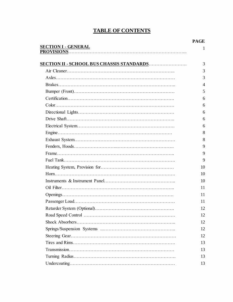
TABLE OF CONTENTS
PAGE
SECTION I - GENERAL PROVISIONS…………………………………………………………………...
1
SECTION II - SCHOOL BUS CHASSIS STANDARDS……………………. 3
Air Cleaner…………………………………………………………….. 3
Axles…………………………………………………………………… 3
Brakes………………………………………………………………….. 4
Bumper (Front)………………………………………………………… 5
Certification……………………………………………………………. 6
Color…………………………………………………………………… 6
Directional Lights……………………………………………………… 6
Drive Shaft…………………………………………………………….. 6
Electrical System………………………………………………………. 6
Engine………………………………………………………………… 8
Exhaust System………………………………………………………… 8
Fenders, Hoods………………………..………………………………. 9
Frame………………………………………………………………….. 9
Fuel Tank………………………………………………………………. 9
Heating System, Provision for………………………………………… 10
Horn……………………………………………………………………. 10
Instruments & Instrument Panel……………………………………….. 10
Oil Filter……………………………………………………………….. 11
Openings………………………………………………………………. 11
Passenger Load………………………………………………………… 11
Retarder System (Optional)……………………………………………. 12
Road Speed Control …………………………………………………… 12
Shock Absorbers……………………………………………………….. 12
Springs/Suspension Systems ...……………………………………….. 12
Steering Gear…………………………………………………………… 12
Tires and Rims…………………………………………………………. 13
Transmission…………………………………………………………… 13
Turning Radius…………………………………………………………. 13
Undercoating…………………………………………………………… 13

Weight Distribution…………………………………………………….. 14
SECTION III - SCHOOL BUS BODY STANDARDS PAGE
Air Conditioning………………………………………………………… 15
Aisle……………………………………………………………………… 15
Back-up Warning Alarm……………………………...…………………. 16
Battery/Batteries………………………………………………………… 16
Bumper (Front)………………………………………………………….. 16
Bumper (Rear)…………………………………………………………… 16
Ceiling…………………………………………………………………… 16
Certification……………………………………………………………… 17
Chains (Tire)…………………………………………………………….. 17
Child Check System……………………………………………………..
Color……………………………………………………………………..
17
17
Communication Systems ………………………………………………. 18
Construction……………………………………………………………… 18
Crossing Control Arm………………………………………………….. 19
Defrosters………………………………………………………………… 19
Doors………..…………………………………………………………… 20
Emergency Exits…………………………………………………………. 21
Emergency Equipment…………………...……………………………… 22
Fire Extinguishers…………………………………………………….. 22
First-Aid Kit………………………………………………………….. 23
Body Fluid Clean-up Kit……………………………...……………… 23
Warning Devices……………………...……………………………… 23
Fire Suppression ………………………………………………………… 23
Floor and Floor Coverings……………………………………………….. 23
Handrail(s) ……………………………………………………………… 24
Heaters…………………………………………………………………… 24
Hinges ………………………………………………………………….. 25
Identification…………………………………………………………….. 26
Inside Height……………………………………………………………. 27
Insulation………………………………………………………………… 27
Interior…………………………………………………………………… 27
Lamps and Signals……………………………………………………….. 28
Metal Treatment…………………………………………………………. 30

Mirrors…………………………………………………………………… 30
Mounting………………………………………………………………… 31
Noise Suppression Switch……………………………………………… 31
Overall Length………………………………………………………….. 31
Overall Width…………………………………………………………... 31
Public Address System ………………………………………………… 31
Retro Reflective Material………………..……………………………….. 31
Rub Rails……………………………………..…………………………. 32
Seat Belt for Driver...……………………………………………………. 33
Seats and Crash Barriers…………………………………………………. 33
Steering Wheel (See Chassis Standards)……………………………….. 34
Steps……………………………………………………………………. 35
Step Treads……………………………………………………………… 35
Stirrup Step……………………………………………………………... 35
Stop Arm Signal…………………………………...……………………. 36
Stop Arm Signal-Rear (Optional) …………………..………………….. 36
Storage Compartment……………………………………………………. 36
Sun Shield……………………………………………………………….. 36
Tailpipe………………………………………………………………….. 36
Traction-Assisting Devices………………...…………………………….. 36
Trash Container and Holding Device……………………...…………….. 37
Undercoating…………………………………………………………….. 37
Ventilation……………………………………………………………….. 38
Video Surveillance Equipment………………………………………….. 38
Wheel Housing…………………………………..………………………. 38
Windshield and Windows……………………………………………….. 39
Windshield Washers…………………………………………………….. 39
Windshield Wipers……………………...……………………………….. 39
Wiring……………………………………………………………………. 40

SECTION IV - SPECIAL NEEDS SCHOOL BUS STANDARDS
Introduction……………………………………………………………… 42
Definition – Specially Equipped School Bus …………………………… 42
General Requirements……………...……………………………………. 42
Air Conditioning……………………………………………………. 43
Aisles…………………………………………………………………. 43
Communication System …………………………………………….. 43
Crash Barriers ……………………………………………………….. 43
Evacuation Blanket………..………………………………………….. 44
Glazing………………………………………………………………. 44
Identification ………………………………………………………... 44
Passenger Capacity Rating…………………………………………. 44
Power Lift…………………………………………………………….. 44
Ramp………………………………………….……………………… 47
Regular Service Entrance…………………………………………….. 47
Restraining Devices………………………………………………….. 48
Seating Arrangements………………………………………………… 48
Securement and Restraint System for Wheelchair/Mobility Aid and
Occupant………………………………………………………………
48
Special Light…………………………………………………………….. 52
Special Service Entrance………………………………………………. 52
Support Equipment and Accessories…………………………………….. 53
SECTION V - ALTERNATE FUEL SOURCE STANDARDS 55
SECTION VI - OPTIONS………………………………………………………. 55
Locking Fuel Compartment Door ……………………………………… 55
Storage Compartment for Required Emergency Equipment…………….. 56

SECTION VII – MULTIFUNCTIONAL SCHOOL ACTIVITY BUS
Definition ………………………………………………………………. 56
Identification ………………………………………………………….… 56
Color ………………………………………………………………… 56
Seating …………………………………………………………….… 56
Lighting and Warning Devices. ……………………………………. 57
Inspections …………………………………………………………….. 57
Regulations ……………………………………………………………. 57
DISPOSAL OF USED SCHOOL BUSES
GUIDELINE FOR THE SAFE TRANSPORTATION OF PRESCHOOL
AGE CHILDRENIN SCHOOL BUSES
SECTION VIII – QUICK REFERENCE CHART
58
59
64

1
ALABAMA MINIMUM SPECIFICATIONS FOR SCHOOL BUSES EFFECTIVE April 1, 2018
SECTION I - GENERAL PROVISIONS
Standards
1. All school buses ordered by local education agencies beginning April 1, 2018, shall (1) meet the applicable Federal Motor Vehicle Safety Standards (FMVSS), and (2) meet
Alabama Minimum Specifications for School Buses. In the event of a conflict between
the requirements of an applicable Federal Motor Vehicle Safety Standard, as referred to in this section, and the Alabama minimum specifications, the requirements of the FMVSS shall control. School buses not meeting minimum specifications will not be
certified by the Alabama State Department of Education (SDE). Under unusual
circumstances and with adequate justification, exceptions to these specifications
may be granted by the SDE Director of Pupil Transportation. Alabama Minimum
Specifications for School Buses shall not be considered as options.
Certification
2. All school buses shall display a durable, legible certification data plate mounted in the driver's compartment of the vehicle. On this data plate, the manufacturer shall certify to the SDE and the local education agency that the school bus meets or exceeds all standards as specified herein, is in compliance with the applicable FMVSS, and is
manufactured from all new components. All chassis and body information shall appear on this certification data plate. The bus body data plate shall specify the maximum design capacity of the body. The maximum design capacity of any bus body size shall be the number of passengers the bus can transport before special needs modifications.
Used School Buses
3. Used school buses purchased for use by a school system in Alabama shall meet all of the legal Federal and Alabama requirements for school buses that were in effect on the date the vehicle was manufactured. It is recommended that school systems contact the SDE Pupil Transportation Office prior to the purchase of any used school bus.
Bid Requirements
4. In order to be in compliance with the State Bid Law, school bus purchases shall be by competitive bidding. Bid forms to the body manufacturer shall contain certain options required by the chassis manufacturer, which may result in changes in normal Gross Vehicle Weight Rating (GVWR) or alterations to the body. For special needs buses, the
school system shall provide the dealers with detailed information regarding desired floor plan. The school bus body manufacturer shall submit floor plans which include dimensions at the time bid quotations are submitted showing:
A. Location of the emergency door, emergency windows and roof hatches.
2
B. Aisle and staging areas and seat spacing.
C. Track locations and/or wheelchair securement positions.
D. Location of air conditioning evaporator(s) for all buses ordered with air conditioning.
5. Service Manual/Diagnostic Equipment
Body and/or chassis suppliers, including integral (forward control) suppliers, shall provide each school district purchasing school buses with one complete set of the most
current service manuals, as specified by the school system, available to include both body and chassis at no additional cost upon delivery of bus. Provisions for manuals and diagnostic equipment, including, but not limited to code books, software, and training, etc., shall be agreed upon during the pre-bid process. Diagnostic equipment shall not be
included as a part of the bus bid and cannot be used to determine low bidder.
6. New Technology
New technology, excluding alternative fuels (see page 51), not in the present specifications shall have written approval from SDE Pupil Transportation prior to the
bid, in collaboration with the School Bus Specifications Committee. No Supervisor
should allow any aftermarket item that is not already approved on an Alabama School
Bus to be installed without consulting ALSDE. A copy of any waiver granted shall be
included in the original bid specifications. In considering such new technology, the
following criteria must be met:
A. The effectiveness or integrity of any major safety system shall not be compromised (i.e., compartmentalization, the eight-lamp warning system, emergency exits, the
approved color scheme). B. The safety of the interior of the bus shall not be diminished. C. No additional risk to students who are boarding or exiting the bus, or are near the
school bus loading zone, shall be created.
D. No undue additional activity and/or responsibility for the driver shall be required. E. The technology, equipment, or component shall:
a. Increase efficiency and/or safety of the bus; b. Provide for a safer, more pleasant experience for the occupants and/or
pedestrians in the bus vicinity; or c. Enhance the driver’s ability to perform his/her many tasks.
3
7. School Bus Definitions
School bus capacity is determined based on body size before modifications are made. TYPE A: A Type A school bus is a conversion or body constructed upon a van-type or
cutaway front-section vehicle with a left side driver’s door designed for
carrying more than 10 persons. This definition shall include two classifications: Type A-I with a GVWR of 10,000 or under; and Type A-II, with a GVWR over 10,000 pounds. All Type A buses shall have dual rear wheels. Type A buses under 14,500 pounds GVWR shall have four-wheel
disc brakes. Type A buses exceeding a GVWR of 14,500 pounds shall have air brakes.
TYPE C: A Type C school bus is a body installed upon a flat back cowl chassis with a GVWR of more than 10,000 pounds and designed for carrying more than 10 persons. The entire engine is in front of the windshield and the entrance door is behind the front wheels. Any type C school bus designed for transporting
37 passengers or more shall be equipped with air brakes. Type C buses may not exceed 78-passenger capacity without prior, written
SDE approval.
TYPE D: A Type D school bus is a body installed upon a chassis, with the engine mounted in the front, midship, or rear, with a gross vehicle weight rating of
more than 10,000 pounds and designed for carrying more than 10 persons. The engine may be behind the windshield and beside the driver's seat, at the rear of the bus, behind the rear wheels, or midship between the front and rear axles. The entrance door is ahead of the front wheels.
Type D buses may not exceed 84-passenger capacity without prior,
written SDE approval.
SECTION II - SCHOOL BUS CHASSIS STANDARDS
Air Cleaner 1. The engine intake air cleaner shall be furnished and properly installed by the chassis
manufacturer to meet engine specifications. The intake air system for diesel engines shall have an air cleaner restriction indicator
properly installed by the chassis manufacturer to meet engine specifications.
Axles 1. The front and rear axles and suspension systems shall have a gross axle weight rating
(GAWR) at ground commensurate with the respective front and rear weight loads of the
bus loaded to the rated passenger capacity.
4
2. Vehicle minimum axle capacities at ground when loaded shall meet the body manufacturer's GVWR specified by the FMVSS. Axle assemblies shall have minimum capacities at ground as shown on the chart on the last page of this booklet.
3. Front wheel bearings must be oil filled on all Type C and D buses.
Brakes 1. A braking system, including service brake and parking brake, shall be provided and shall
comply with all CDL pre-trip inspection requirements. All Type A-1 and A-II school
buses below 14,500 pounds GVWR shall be built to manufacturer’s specifications. 2. Buses using air in the operation of the brake system shall be equipped with warning
signals located within the interior of the driver compartment and clearly audible and
visible to the driver, that will give a continuous warning when the air pressure available in the system for braking is 60 psi (pounds per square inch) or less. An air pressure gauge shall be provided in the instrument panel capable of complying with CDL pre-trip inspection requirements.
3. Antilock brake systems for either air or hydraulic brakes shall include control of all
axles in compliance with FMVSS 105 or 121.
A. Air brakes shall be installed on all buses designed to transport more than 36 passengers. As an option, air-disc brakes may be installed on Type C and D school buses. On buses with a capacity of 36 or less, if hydraulic brakes are used, they must be four-wheel disc.
All air-operated brake systems shall:
(1) Meet all Federal Motor Vehicle Safety Standards (FMVSS) for air brakes.
(2) Be S-cam or four-wheel-disc-type brakes. Air-disc brakes may be installed on
Type C and D school buses with approval from the SDE. If S-cam-type, the camshaft, when applying brakes, shall rotate in the same direction as the wheels.
Automatic slack adjusters shall be the same design on all wheels. Dust covers shall be installed on all wheels unless deleted through local option at the time of the bid.
(3) Have at least a 12 CFM air compressor.
(4) Be equipped with a parking and emergency brake. A manual control, clearly identified, shall be within easy reach of the driver. The parking brake valve shall
comply with CDL pre-trip inspection requirements.

5
(5) Have brake lining sizes as shown on the chart on the last page of this booklet (S-cam air brakes)
(6) Have a reservoir capacity, which is equal to or greater than two (2) times total volume of all brake activators at full travel.
(7) Be equipped with air dryers with a heated automatic drain valve (Bendix AD-9
or AD/IP) or prior approved equal. Air dryers shall be serviceable at the local level.
B. Buses using a hydraulic assist-booster in the operation of the brake system shall be
equipped with warning signals, readily audible and visible to the driver, that will provide continuous warning in the event of a loss of fluid flow from the primary source, or loss of electric source powering the back-up system.
(1) The system shall be equipped with a source of hydraulic pressure, automatically initiated upon loss of power from primary source, and operating independently of the primary power source.
(2) All brake systems shall be designed to permit visual inspection of brake lining wear without the removal of any chassis components.
4. All buses shall have either a parking pawl in the transmission or a park brake
interlock that requires the service brake to be applied to allow release of the parking
brake.
Bumper, Front
1. The front bumper shall be furnished by the chassis manufacturer for all school bus types, unless there is specific agreement between the chassis manufacturer and the body manufacturer. When Type D chassis are supplied to a body company by a chassis manufacturer, the body company shall supply the front bumper as part of the body
installation.
2. The front bumper shall be of pressed steel channel or equivalent material at least
3/16 inch thick, not less than 8 inches wide (high) and shall extend beyond forward- most part of the body, grille, hood, and fenders and shall extend to the outer edges of the fenders at the bumper's top line. Bumpers on Type A buses may be built to manufacturers’ specifications.
3. Tow eyes or hooks shall be furnished and attached so as not to project beyond the front
bumper. Tow eyes or hooks, attached to the frame chassis, shall be furnished by the chassis manufacturer. This installation shall be in accordance with the chassis
manufacturer's standards. Type A buses are exempt from tow hook requirements.

6
4. The bumper shall be designed or reinforced so that it will not deform, when the bus is lifted by a chain that is passed under the bumper (or through the bumper if holes are provided for this purpose) and attached to both tow eyes. For the purpose of meeting
this standard, the bus shall be empty and positioned on a level, hard surface, and both tow eyes shall share the load equally. The front bumper shall not be deformed when lifted by a bumper jack positioned on the bumper attachment points.
Certification The chassis manufacturer shall certify to the SDE and local education agency having pupil transportation jurisdiction that their product meets minimum standards on items
not covered by certification issued under requirements of the National Traffic and Motor Vehicle Safety Act.
Color 1. The chassis, including the front bumper, shall be black. The hood, cowl and fenders
shall be in national school bus yellow. The hood may be painted with non-reflective paint.
2. Wheel rims shall be painted black, gray, or yellow on all buses.
3. Multifunctional School Activity Buses (MFSAB) shall be exempt from these requirements. (See MFSAB specifications on page 53.)
Directional Lights 1. Each Type C chassis may be equipped with Type A front directional lights of the two-
faced type mounted on the top of the fender and the hood side panel, or have an amber
turn signal and marker light that is an integral part of the headlight assembly. This turn signal/marker light shall be seen from the front and the side of the vehicle.
Drive Shaft
1. Torque capacity of the drive shaft assembly shall at least equal maximum engine torque as developed through lowest transmission gear reduction.
2. Each drive shaft shall be equipped with protective metal guard or guards to reduce the
possibility of it whipping through the floor or dropping to the ground if broken. (The body manufacturer is responsible for Mini Buses.)
Electrical System
1. Battery A. Storage batteries shall have a minimum total of 1,500 cold cranking amps at 0
degrees Fahrenheit. Type A buses shall be built to manufacturer’s specifications.
B. All school buses shall have a battery-disconnect device installed. On Type C and D school buses, the disconnect switch shall be located in the battery compartment. The location of the disconnect switch on Type A school buses shall be agreed upon by the local school system and the bus supplier. A battery disconnect decal shall be
placed on the outside of the bus to identify the location.

7
2. Alternator
A. All Type A buses up to 15,000 lbs. GVWR shall have a minimum 130 amperes
alternator. B. All C and D buses over 15,000 lbs. GVWR shall be equipped with a heavy-duty
truck or bus-type alternator capable of producing a minimum output rating of 200
amperes. The alternator shall be capable of producing a minimum of 50 percent of its maximum rated output at the engine manufacturer's recommended idle speed.
C. All C and D buses equipped with an air conditioner or electrical power lift shall have
a minimum 270 amperes alternator. D. A direct-drive alternator is permissible in lieu of a belt drive. A belt drive shall be
capable of handling the rated capacity of the alternator with no detrimental effect on
other driven components. E. Refer to SBMTC Design Objectives, most current edition, for estimating required
alternator capacity.
3. Wiring
A. All wiring shall conform to current applicable recommended practices of the Society of Automotive Engineers.
(1) All wiring shall use standard colors and number coding and each chassis shall be delivered with a wiring diagram that coincides with the wiring of the chassis.
All wires passing through metal openings shall be protected by a grommet or loom.
B. The chassis manufacturer shall install a readily accessible terminal strip or plug on
the body side of the cowl, or at an accessible location in the engine compartment of vehicles designed without a cowl, that shall contain the following terminals for the body connections:
(1) Main 100-amp body circuits (2) Tail lamps (3) Right turn signal (4) Left turn signal
(5) Stop lamps (6) Back-up lamps (7) Instrument panel lights (rheostat controlled)
C. Daytime running lamps shall be provided.
4. Circuits A. An appropriate identifying diagram (color and number coded) for electrical circuits
shall be provided to the body manufacturer for distribution to the end user.
8
Engine Fire Extinguisher (Optional)
See Fire Suppression System page 22.
Engine Information
1. Buses shall be equipped with diesel engines with minimum horsepower requirements as follows:
Type A buses under 29 passenger – manufacturer’s specifications Type C or D buses –210 hp minimum Type D buses 78 passengers and above – 230 hp minimum
An engine heater may be installed as per the manufacturer's specifications.
Alternative-fuel engine information can be found on page 51, under Alternative Fuel
Standards.
The retro-fitting of existing school bus engines for alternative fuel use is prohibited.
Exhaust System 1. The exhaust pipe, muffler after treatment device, and tail pipe shall be outside the bus
body and securely attached to the bus frame. The chassis manufacturer shall furnish
an exhaust system with a tail pipe of sufficient length to exit the rear of the bus or at the left side of the bus body no more than 18 inches forward of the front edge of the rear wheelhouse opening. If designed to exit on the side of the bus, the tailpipe shall extend to the skirt line with a turndown angle of approximately 45 degrees. With the
exception of special needs buses, Type A vehicles may have the manufacturers standard exhaust system. The bus shall not automatically begin to regenerate the diesel particulate filter while the bus is not moving. The switch to regenerate the diesel particulate filter shall be readily accessible to the technician, but not accessible
to the driver 2. The muffler and the tail pipe shall be constructed of aluminized, or equivalent
corrosion resistant material. The tailpipe shall be made of at least 16 gauge material
and shall be mounted in such a way that it will not cause damage to brake lines
3. The muffler after treatment device, and exhaust pipe shall be properly insulated from the fuel tank, lines, and connections by a protective shield at any point where it is 4
inches or less from the fuel tank, lines or connections. 4. The tailpipe on all special needs vehicles shall be routed to the left of the left frame
rail to allow for the installation of a lift on the right side of the vehicle.
5. No exhaust pipe shall exit beneath an emergency exit or the fuel fill.

9
6. On all Type C and D buses, the tailpipe shall exit at the bottom edge of the rear bumper or through the rear bumper. If the tailpipe exits through the rear bumper, sufficient clamps or brackets must be provided to eliminate rattles. If the tailpipe
exits beneath the rear bumper, it shall be turned down approximately 45 degrees and positioned in such a way that it cannot be crushed beneath the rear bumper.
The opening in the tailpipe shall direct all exhaust gases clear of the perimeter of the bus
body. Manufacturers must make reasonable efforts to ensure that exhaust gases will not produce burns on students or other individuals present.
Fenders, Hoods
1. The total spread of outer edges of front fenders, measured at the fender line, shall exceed the total spread of the front tires when the front wheels are in a straight-ahead position.
2. Front fenders shall be properly braced and free from any body attachments.
3. A fiberglass or other reinforced resin composite tilt hood shall be provided. The hood
opening and closing effort shall be minimized to aid the driver with pre-trip inspections and service. If the hood is not designed to remain secure in the open position, a safety
prop will be required. The wiring harness shall be a “quick disconnect” type to aid with servicing.
Frame
1. The frame or equivalent shall be of such design and strength characteristics as to correspond at least to standard practice for trucks of the same general load characteristics, which are used for highway service.
2. Any secondary manufacturer that modifies the original chassis frame shall guarantee the performance of workmanship and materials resulting from such modification.
3. Any frame modification shall not be for the purpose of extending the wheelbase.
4. Holes in top or bottom flanges or side units of the frame, and welding to the frame, shall
not be permitted except as provided or accepted by the chassis manufacturer.
5. Frame lengths shall be provided in accordance with current SBMTC Design Objectives.
Fuel Tank 1. All Type C and D chassis above a 170-inch wheelbase shall have a minimum 60-gallon
fuel tank with a 55-gallon actual draw. The tank shall be filled and vented to the outside of the body, the location of which shall be so that accidental fuel spillage will not drip or drain on any part of the exhaust system.
2. No portion of the fuel system, which is located to the rear of the engine compartment, except the filler tube, shall extend above the top of the chassis frame rail. Fuel lines shall be mounted to obtain maximum possible protection from the chassis frame.

10
3. Fuel filters shall be installed as per manufacturer's specifications. Fuel filtration shall
include water detection and separation. At least one fuel filter shall have a replaceable
spin-on or cartridge-type element.
4. Fuel tank installation shall be in accordance with current SBMTC Design Objectives for location on the chassis right frame rail or between frame rails; the filler tube shall be
located on the right side of the bus. 5. Type A buses may meet manufacturer's specifications.
6. The fuel tank on vehicles constructed with a power lift unit may be mounted on the left chassis rail or behind the rear wheels.
7. Installation of alternative fuel tanks shall comply with all applicable fire codes.
8. The fuel tank shall be designed to prevent fuel starvation on inclines.
Heating System, Provision for 1. The chassis engine shall have plugged openings for the purpose of supplying hot water
for the bus heating system. The opening shall be suitable for attaching a pipe thread/hose connector. The engine shall be capable of supplying water having a
temperature of at least 170 degrees Fahrenheit at a flow rate of 50 pounds/per minute at the return end of 30 feet of one inch inside diameter automotive hot water heater hose (SBMI Standard No. 001--Standard Code for Testing and Rating Automotive Bus Hot Water Heating and Ventilating Equipment).
Horn Buses shall be equipped with a horn or horns of standard make with each horn capable of producing a complex sound in bands of audio frequencies between 250 and 2,000 cycles per
second and tested per the Society of Automotive Engineers Standard J--377. There shall be no air horns.
Instruments and Instrument Panel
1. Chassis shall be equipped with the following instruments and gauges (lights in lieu of gauges are not acceptable except as noted):
A. Speedometer
B. Odometer (shall show accrued mileage to six digits not including tenths)
C. Tachometer
D. Voltmeter
(1) An ammeter with graduated charge and discharge and its wiring compatible with generating capacities is permitted in lieu of a voltmeter.
11
E. Oil-pressure gauge
F. Water temperature gauge
G. Fuel gauge
H. Upper beam headlight indictor
I. Air brake indicator gauge
(1) A light indicator in lieu of a gauge is permitted on vehicles equipped with a hydraulic-over-hydraulic brake system.
J. Turn signal indicator
K. Glow-plug indicator light where appropriate
L. A twelve-volt accessory outlet with cover
2. All instruments shall be easily accessible for maintenance and repair.
3. Instruments and gauges shall be mounted on the instrument panel in such a manner that each is clearly visible to the driver while in a normal seated position in accordance with current SBMTC Design Objectives.
4. The instrument panel shall have lamps of sufficient candlepower to illuminate all instruments and gauges and the shift selector indicator for an automatic transmission.
Oil Filter
An oil filter with replaceable element shall be provided and connected by flexible oil lines if it is not of built-in or engine-mounted design. The oil filters shall have a capacity of at least one (1) quart.
Openings All openings in the floorboard or firewall between the chassis and the passenger-carrying compartment, such as for gearshift selector and parking brake lever, shall be sealed.
Passenger Load 1. Actual GVW is the sum of the chassis weight, plus the body weight, plus the driver's
weight, plus total seated pupil weight. For purposes of calculation, the driver's weight
is 150 pounds. For purposes of calculation, the pupil weight is 120 pounds per pupil. 2. Actual GVW shall not exceed the chassis manufacturer's GVWR for the chassis, nor shall the actual weight carried on any axle exceed the chassis manufacturer’s Gross
Axle Weight Rating. (GAWR)

12
Retarder System (Optional) A retarder system, if used, shall limit the speed of the fully loaded school bus at 19.0 mph or 30 km/hr on a 7% grade for 3.6 miles or 6 km.
Road Speed Control When it is necessary to control vehicle maximum speed, a vehicle speed limiter shall be utilized. For Type C and D buses, and where feasible on Type A buses, bus road speed shall
not exceed a maximum of 70 miles per hour.
Shock Absorbers Buses shall be equipped with front and rear double-action shock absorbers compatible with
the manufacturer’s rated axle capacity at each wheel location.
Springs/Suspension Systems 1. The capacity of the springs or suspension assemblies shall be commensurate with the
chassis manufacturer’s GVWR.
2. Front springs shall be of the leaf type, shall have a stationary eye at one end, and shall be protected by a wrapper leaf in addition to the main leaf. Rear leaf springs shall be of
the progressive type. 3. Air ride suspension may be used on the front and rear of Type C and D buses in lieu of
leaf-type springs. Body and chassis parts must clear tires with air bags in fully deflated
condition or steering wheel turned fully to the left or right. If brake dust covers are used, inspection holes of adequate size and location for easily viewing brake linings shall be provided.
Steering Gear 1. The steering gear shall be approved by the chassis manufacturer and designed to assure
safe and accurate performance when the vehicle is operated with maximum load and at maximum speed.
2. If external adjustments are required, the steering mechanism must be accessible to
accomplish the same.
3. No changes shall be made in the steering apparatus, which are not approved by the chassis manufacturer.
4. There shall be a clearance of at least two inches between the steering wheel and the
cowl, instrument panel, windshield, or any other surface. 5. Power steering is required and shall be of the integral type with integral valves.
6. The steering system shall be designed to provide a means for lubrication of all wear-points, if wear-points are not permanently lubricated.

13
7. The steering wheel shall meet manufacturer’s specifications.
Tires and Rims 1. Radial tubeless tires, rims of proper size and tires with a load rating commensurate with
chassis manufacturer’s GVWR shall be provided. Hubcaps are not permitted.
2. Dual rear tires shall be provided on all school buses.
3. All tires on any given vehicle shall be of the same size and the load range of said tires shall meet or exceed the gross axle weight rating as required by FMVSS 120. Low profile tires are acceptable. However, they must meet the load range and ply
requirements as shown on the chart on the last page of this booklet. It is recommended that dish-type rims be used with low profile tires.
4. If the vehicle is equipped with a spare tire and rim assembly, it shall be of the same size as those mounted on the vehicle.
5. If a tire carrier is required, it shall be suitably mounted in an accessible location outside the passenger compartment.
Transmission
An automatic transmission shall be required on all school buses, and shall be designed to perform the functions of school bus operation Type A buses may be built to manufacturer’s specifications. Types C, and D buses must have a PTS 2000 series. Allowable transmissions will include Allison 2000 series, Allison 3000 series, Ford 6R140, and Eaton Procision
automatic transmissions. The automatic transmission shall have at least four forward-gear ratios. The transmission shift quadrant shall provide at least four forward drive ranges plus neutral and reverse ranges. Within the range selected, ratio changes shall be effected automatically and at full engine power if desirable, and without use of an engine disconnect
clutch. A PTS3000 or prior approved equal is required for chassis over 33,000 pounds GVWR.. Please refer to the “New Technology” section for any exceptions.
Turning Radius
1. A chassis with a wheelbase of 264 inches or less shall have a right and left turning radius of not more than 42 1/2 feet, curb-to-curb measurement.
2. A chassis with a wheelbase of 265 inches or more shall have a right and left turning
radius of not more than 44 and 1/2 feet, curb-to-curb measurement.
Undercoating The chassis manufacturer, or agent thereof, shall coat the undersides of steel or metallic-
constructed front fenders with a rust-proofing compound for which compound manufacturers have issued notarized certification of compliance to the chassis builder that the compound meets or exceeds all performance and qualitative requirements of paragraph 3.4 of Federal Specification TT-C520B using modified tests.

14
Weight Distribution The weight distribution of a fully loaded bus on a level surface shall be such as not to exceed the manufacturer’s front gross axle rating and rear gross axle weight rating.

15
SECTION III - SCHOOL BUS BODY STANDARDS
Air Conditioning All special needs buses shall be equipped with air conditioning. Other buses may be
equipped with an air conditioning unit at the discretion of the local school system. Type A school buses may be built to manufacturers standards to include dash mounted evaporator and air duct systems. All Type C and D buses are required to have bulkhead
mounted rear air conditioner evaporator systems. Front mounted evaporator units on Type C and D buses may include bulkhead-mounted or dash-mounted evaporator units. All other evaporator units shall be side-mounted so as not to interfere with the entrance or exit or any wheelchair position. Evaporator placement shall be agreed upon by the school system and the
school bus manufacturer. Low profile, roof-mount condenser units may be installed upon agreement between the manufacturer and the local school system.
All buses ordered with air conditioning shall meet the following minimum specifications:
1. All flooring shall be 5/8-inch exterior-grade plywood over steel flooring.
2. All passenger windows shall be tinted with 28% light transmission. 3. All buses shall meet insulation standards as per Alabama bus specifications. 4. Mud flaps shall be installed behind both the front and rear axles on all buses equipped
with skirt-mounted air conditioning.
5. All buses/engines shall be equipped with an automatic high-idle feature. 6. All air conditioning components must be rated to meet minimum BTU specifications
shown below.
Minimum BTU air conditioning system per passenger size (per shell size):
10-30-passenger - 60,000 BTU includes a minimum of one, 13 cubic inch displacement compressor
31-48-passenger – 75,000 BTU includes a minimum of two, 10 cubic inch displacement compressors
or a single minimum 400cc compressor
49-66-passenger - 96,000 BTU includes a minimum of two, 10 cubic inch displacement compressors
or a single minimum 400cc compressor 67passenger and over - 120,000 BTU includes a minimum of two, 13 cubic inch displacement
compressors or a single minimum 400cc compressor
7. Skirt-mounted condenser units shall be designed so as to draw sufficient fresh air from
outside the skirt area and shall have a shroud installed to protect the condenser unit from road dirt and debris. Condensers must have continuous ducting or shrouding from the condenser to the grating at the body side to ensure that condensers do not recirculate the hot air leaving the condenser.
Aisle All emergency doors shall be accessible by a 12-inch minimum aisle. The aisle shall be unobstructed at all times.

16
Back-Up Warning Alarm An automatic, audible alarm with a minimum of 87dbA and maximum of 112dbA shall be installed behind the rear axle and shall comply with the Society of Automotive Engineers
published Back-up Alarm Standards (SAE 994). The alarm shall have a protective deflector shield.
Battery/Batteries 1. Batteries are to be furnished by the chassis manufacturer.
2. Batteries are to be mounted as described in the Chassis Standard (see Electrical System 1B).
3. On type C and D buses, the body manufacturer shall securely attach the battery on a slide-out or swing-out tray in a closed, vented compartment in the body skirt, so that
the battery is accessible for convenient servicing from the outside. The battery compartment door or cover shall be hinged at the front and secured by an adequate and conveniently-operated latch or other type fastener.
Bumper (Front) On a Type D school bus, if the chassis manufacturer does not provide a bumper, it shall be provided by the body manufacturer. The bumper will conform to the standards in the chassis section.
Bumper (Rear) 1. Bumpers shall be of pressed steel channel or equivalent material, at least 3/16-inch
thick, and shall be a minimum of 9-1/2 inches wide (high) on all Types C, and D buses.
Type A buses shall have a minimum of an 8-inch rear bumper. 2. Bumpers shall be wrapped around the back corners of the bus. It shall extend forward at
least 12 inches, measured from the rear-most point of the body at the floor line.
3. Bumpers shall be attached to the chassis frame in such a manner that it may be easily
removed. It shall be so braced as to withstand impact from a rear or side impact. It shall be so attached as to discourage hitching of rides.
4. Bumpers shall extend at least one inch beyond the rear-most part of the body surface
measured at the floor line.
5. Tow eyes or hooks may be furnished on the rear and attached so they do not project beyond the rear bumper. The installation shall be in accordance with the chassis manufacturer’s specifications.
6. The bottom of the rear bumper shall not be more than 30 inches above ground level.
Ceiling See Insulation and Interior, Body Standard.

17
Certification The body manufacturer shall certify to the SDE and the local education agency having pupil
transportation jurisdiction that their product meets minimum standards on items not covered by certification issued under requirements of the National Traffic and Motor Vehicle Safety Act.
Chains (Tire) See Wheel Housing Body Standard.
Child Check System – (not brand specific)
A child check system shall be provided meeting the following specifications:
The child check system shall activate when the eight-way warning lights have been activated and fully cycled.
Once the child check system has been activated, the following procedures must take place
before the driver can exit the bus (open the entrance door) without the horns sounding until
the system is deactivated. 1. The door must be closed before the ignition is turned off, and the Parking Brake must
be set.
2. After the ignition is turned off or the key is turned to the accessory position, the driver
must walk to the rear of the bus and manually operate a deactivation switch, which
shall be located above the rear door in the rear bulkhead and clearly labeled.
3. Immediately upon deactivating, the interior dome light or such indicators shall
activate to identify the system has disarmed.
4. The interior dome light shall illuminate and remain on for a minimum of 60 seconds
after deactivating.
5. Any attempt to exit the bus by opening the entrance door will sound the horn until the
system has been de-activated.
Color
1. The school bus body shall be painted National School Bus Yellow. 2. The body exterior paint trim, bumper, lamp hoods and lettering shall be black.
3. The roof of the bus must be painted white not to extend below the drip rails on the sides of the body.
4. Multifunctional School Activity Buses shall be exempt from this requirement. (See
MFSAB specifications on page 53.)
18
Communication Systems Each bus shall be equipped with a two-way, voice communication system capable of
providing communication with the operational base. Where technologically feasible, the communication system shall also communicate with 911 operators. CB radio systems will not meet this requirement. It is the responsibility of the local school system to comply with this specification.
Construction 1. Construction shall be of prime commercial quality steel or other material with strength
at least equivalent to all-steel as certified by the bus body manufacturer. All such
construction materials shall be fire resistant. No exterior structural, fiberglass roof or side panels are allowed. All Type C and D school buses shall meet the requirements of Section A below.
A. Side Intrusion Test: The bus body shall be constructed to withstand an intrusion force equal to the curb weight of the vehicle or 20,000 pounds, whichever is less. Each vehicle shall be capable of meeting this requirement when tested in accordance with the procedures set forth below. The complete body structure, or a representative seven-body
section mock up with seats installed, shall be load-tested at a location 24±2 inches above the floor line, with a maximum 10 inch diameter cylinder, 48 inches long, mounted in a horizontal plane.
The cylinder shall be placed as close as practical to the mid-point of the tested structure, spanning two internal vertical structural members. The cylinder shall be statically loaded to the required force of curb weight or 20,000 pounds, whichever is less, in a horizontal plane with the load applied from the exterior toward the interior of the test structure.
When the minimum load has been applied, the penetration of the loading cylinder into the passenger compartment shall not exceed 10 inches from its original point of contact. There can be no separation of lapped panels or construction joints. Punctures, tears or breaks in the external panels are acceptable but are not permitted on any adjacent interior
panel. Body companies shall certify compliance with this intrusion requirement to the Alabama State Department of Education and include test results, as requested.
2. Construction shall be dust proof and watertight, so the bus does not leak under normal
operating conditions. 3. Body joints present in that portion of a Type A school bus body furnished exclusively by
the body manufacturer shall conform to the performance requirements of FMVSS 221,
“School Bus Body Joint Strength.” This does not include the body joints created when body components are attached to components furnished by the chassis manufacturer.
4. Type A school bus bodies shall be equipped with restraining barriers conforming to
FMVSS 222, “School Bus Passenger Seating--Crash Protection,” Sections 5.2 and 5.3.

19
Crossing Control Arm 1. Buses shall be equipped with a crossing control arm mounted on the right side of the
front bumper, which shall not open more than 90 degrees.
2. All components of the crossing control arm and all connections shall be
weatherproofed.
3. The crossing control arm shall incorporate system connectors (electrical or air) at the gate and shall be easily removable to allow for towing of the bus.
4. The crossing control arm shall meet or exceed SAE Standard J1133.
5. The crossing control arm shall be constructed of non-corrosive or nonferrous material
or treated in accordance with the body sheet metal standard (see Metal Treatment).
6. There shall be no sharp edges or projections that could cause hazard or injury to students.
7. The crossing control arm shall extend at least 70” from the front bumper when in the
extended position. 8. The crossing control arms shall extend simultaneously with the stop arm(s) by means of
the stop arm controls. An automatic recycling interrupt switch shall be installed to
allow the driver to deactivate the control arm when necessary. 9. An electromagnetic device or a stowed bracket shall be installed to stabilize the arm
when in the stored position.
10. The crossing control arm shall be Specialty Manufacturing Company, Part #58600,
Transpec 4000 series, or prior approved equal.
Defrosters 1. The windshield defroster and defogging system shall provide defogging of the entire
windshield, driver’s side window, and entrance door glasses by utilizing hot air taken
from the heater core with vents across the entire windshield. 2. The defrosting system shall conform to Society of Automotive Engineers’ Standards
J381.
3. The defroster and defogging system shall be capable of furnishing heated outside
ambient air.
4. Auxiliary fans are not considered defrosting or defogging systems. 5. Portable heaters shall not be used.

20
Doors 1. Service Door:
A. The service door shall be in the driver’s control, designed to afford easy release and
provide a positive latching device on manual operating doors to prevent accidental opening. When a hand lever is used, no part shall come together that will shear or
crush fingers. Manual door controls shall not require more than 25 pounds of force to operate at any point throughout the range of operation.
B. The service door shall be located on the right side of the bus, opposite and within
direct view of the driver. C. The service door shall have a minimum horizontal opening of 24 inches and a
minimum vertical opening of 68 inches.
D. The service door shall be a split type, both sections opening outward. E. Lower and upper door panels shall be of approved safety glass. The bottom of each
lower glass panel shall not be more than 10 inches from the top surface of the bottom step. The top of each upper glass panel shall not be more than 6 inches from the top of the door.
F. Vertical closing edges on split type entrance doors shall be equipped with flexible material to protect students’ fingers.
G. There shall be no door to the left in driver compartment on Types C or D vehicles.
H. All doors shall be equipped with padding at the top edge of each door opening. The
pad shall be at least three inches wide and one inch thick and extend the full width of the door opening.
I. If air or electric doors are used, the amber warning lights shall be activated from a
momentary switch. A three-position switch, located on the panel to the right side of the driver, shall activate the sequence as follows:
Position One – door closed; lights off. Position Two – activate red lights, stop arm, and crossing control arm. Position Three – red lights activated, door open, stop arm activated, and crossing control arm activated.

21
Emergency Exits 1. Emergency Door:
A. The emergency door shall be hinged on the right side if in the rear end of bus and on the front side if on left or right side of the bus. It shall open outward and be labeled inside to indicate how it is to be opened. If double emergency doors are used on Type A vehicles, they shall be hinged on the outside edge and shall have a three-
point fastening device. A device shall be used that holds the door open to prevent the emergency door from closing during emergencies and school bus evacuation drills. If emergency door locks are used, the vehicle ignition must be disabled until the emergency door lock is deactivated.
B. The upper portion of the emergency door shall be equipped with approved safety
glazing, the exposed area of which shall be at least 400 square inches. The lower portion of the rear emergency door on Types C and D vehicles shall be equipped
with a minimum of 350 square inches of approved safety glazing. C. There shall be no steps leading to an emergency door.
D. The words EMERGENCY DOOR in letters at least two inches high shall be placed at the top of or directly above the emergency door or on the door in the metal panel above the top glass, both inside and outside of the bus. The words EMERGENCY
EXIT in letters at least 2 inches high shall be placed on the exterior body directly
above each emergency window. E. The emergency door shall be equipped with padding at the top edge of each door
opening. Padding shall be at least three inches wide and one inch thick, and extend
the full width of the door opening. F. The side emergency door, if installed, must meet the requirements as set forth in
FMVSS 217 (a), regardless of its use with any other combination of emergency
exits.
(1) A left side emergency door shall have a 20 inch unobstructed passageway, and no flip seat is to be used. A barrier shall be used just before the door opening.
G. There shall be no obstruction higher than 1/4 inch across the bottom of any
emergency door opening.
22
2. Additional Emergency Exits: A. All school buses shall be equipped with emergency exits based on the maximum
designed capacity:
0 to 54 passenger: one emergency window exit per side and one roof hatch located midpoint.
55 passenger and above: two emergency window exits per side, and two roof hatches.
B. Each emergency exit shall comply with FMVSS 217. These emergency exits are in
addition to the rear emergency door or exit. Roof hatches must be Transpec Standard Vent, Model 1970, Specialty Manufacturing 8600, 8900, or 9000 series, Spheros #550886A or 550887A, or prior approved equal.
(1) Emergency exit windows shall be as evenly spaced as possible under FMVSS 217 guidelines and shall not be obstructed by any devices.
C. In addition to the audible warning required on emergency doors by FMVSS 217,
additional emergency exits shall also be like protected. Warnings for these exits shall be clearly audible to the bus driver.
D. School bus emergency exits shall be marked with a minimum one inch wide strip of
red, white, or yellow retro-reflective tape, to be placed around the outside perimeter of the emergency exit opening, not the emergency exit itself. The words EMERGENCY EXIT, in letters at least two inches high, shall be placed on the body directly above each emergency window.
Emergency Equipment All emergency equipment shall be installed forward of the front barriers with the exception of the warning devices.
1. Fire Extinguishers:
A. The bus shall be equipped with at least one steel-cased, pressurized, dry chemical fire extinguisher complete with hose to meet Underwriters Laboratories, Inc.,
approval. A pressure gauge shall be mounted on the extinguisher and easily read without moving the extinguisher from its mounted position. Replacement fire extinguishers should also meet this specification.
The bracket shall be a heavy-duty, snap-in, spring type. Band type holders are not acceptable. Fire extinguisher brackets shall be Brooks Equipment Company # 4SC or Ridgeway Bus Products # 51-05 or prior approved equal.
B. The fire extinguisher shall have a capacity of five pounds with an Underwriters Laboratories total rating of 2A10BC or greater. The operating mechanism shall be sealed with a type of seal that will not interfere with the use of the fire extinguisher.
C. Fire extinguishers must comply with State Fire Codes.
23
2. First-Aid Kit:
A. Each bus shall have a removable, moisture-proof and dust-proof first-aid kit stored
in a metal container and mounted with a separate bracket in an accessible place in the driver’s compartment. This place shall be marked to indicate its location. Strap-type mounting brackets are not acceptable.
B. Contents shall include: 2 1” x 2 1/2 yards adhesive tape rolls 24 sterile gauze pads 3” x 3” 100 3/4” x 3” adhesive bandages
8 2” bandage compress 10 3” bandage compress 2 2” x 6” sterile gauze roller bandages 2 non-sterile triangular bandages approximately 40” x 36” x 54” with
2 safety pins 3 sterile gauze pads 36” x 36” 3 sterile eye pads 1 pair rounded-end scissors
1 pair latex gloves 1 mouth-to-mouth airway
3. Body Fluid Clean-up Kit:
Each bus shall have a removable and moisture-proof body fluid clean-up kit stored in a metal container. Strap-type mounting brackets are not acceptable. It shall be properly mounted and identified as a body fluid clean-up kit and must meet OSHA regulations.
4. Warning Devices:
Each bus shall contain at least three (3) reflectorized triangle road warning devices mounted in an accessible place in the driver’s compartment or the outside storage
compartment. The mounting location in Type A vehicles is optional. These devices must meet requirements in FMVSS 125.
Fire Suppression (Optional)
When a fire suppression system is used, nozzles for suppression systems shall be located in the engine compartment, under the bus, in the electrical panel, or under the dash, but shall not be located in the passenger compartment. The system must include a light or buzzer to alert the driver that the system has been activated.
Floor and Floor Coverings 1. The floor in the under-seat area, including the tops of the wheel housing, driver’s
compartment and toe board, shall be covered with a rubber floor covering or equivalent,
having a minimum overall thickness of 1/8 inch and a calculated burn rate of 0.1 or less using the test measures, procedure and formulas in FMVSS 302 Flammability of Interior Materials.

24
2. The floor covering in the aisle shall be of aisle-type rubber or equivalent, wear resistant,
and ribbed. The minimum overall thickness shall be 3/16 inch measured from the tops
of the ribs. 3. The floor covering must be permanently bonded to the floor and must not crack when
subjected to sudden changes in temperature. Bonding or adhesive material shall be
waterproof and shall be of a type recommended by the manufacturer of the floor-covering material. All seams must be sealed with waterproof sealer.
4. For Type C and D school buses, the manufacturer shall provide a screw-down plate to
access the fuel tank sending unit that is secured and insulated. The plate shall be mounted so that access is readily available to repair personnel and so that the floor covering is not disturbed during the repair process.
5. The floor shall be of metal or alloy at least equal in strength to 14-gauge prime commercial quality steel and so constructed that exhaust gases cannot enter the passenger compartment.
6. All closures between the bus body and the engine compartment shall be fitted with gas-tight gaskets and pedal openings shall be closed bellows type, gas-tight boots.
7. There shall be a plate of adequate size provided to allow for transmission access
or service.
Handrail(s) At least one handrail shall be installed. The handrail(s) shall assist passengers during entry
or exit, and shall be designed to prevent entanglement as evidenced by the passage of the NHTSA string and nut test. A right-hand side assist rail may be provided at the discretion of the local school system.
Heaters 1. The heating system shall be capable of maintaining the temperature throughout the
bus of not less than 55 degrees Fahrenheit during average minimum January temperatures as established by the U. S. Department of Commerce, Weather Bureau,
for the area in which the vehicle is to be operated. It shall be capable of defrosting the total windshield area and the service door glass within thirty minutes after initial start with the engine at idle speed. The system shall exceed SAE standards J-381performance requirements. Fuel-fired auxiliary heaters will not be allowed.
Heater performance shall be measured by the following: A temperature measurement shall be taken at three locations within the body in the center
aisle, thirty-six inches above the floor. The first location is to be thirty-nine inches from the windshield; the second location midpoint of the passenger compartment and the third will be thirty-nine inches from the rear emergency door.

25
After soaking the bus at twenty degrees F. for fifteen (15) hours, the bus will be started and after thirty (30) minutes, the temperature at each measuring point shall be fifty-five
(55) degrees F.
2. If only one heater is used, it shall be a fresh-air or combination fresh-air and recirculation type.
3. If more than one heater is used, additional heaters shall be a recirculating-air type.
4. All heaters installed by body manufacturers shall bear a name plate affixed by the heater
manufacturer that shall indicate the heater rating in accordance with SBMI Standard No. 001.The heater manufacturer shall constitute certification that the heater performance is as shown on the plate.
5. Heater hoses shall be adequately supported to guard against excessive wear due to vibration. The hoses shall not dangle or rub against the chassis or sharp edges and shall not interfere with or restrict the operation of any engine function. Heater hoses shall conform to the Society of Automotive Engineers’ Standard J20c. Heater lines on the
interior of the bus shall be shielded to prevent scalding of the driver or passengers.
6. Each hot water system installed by a body manufacturer shall include one shut-off valve in the pressure line and one shut-off valve in the return line with both valves at or near
the engine in an accessible location. 7. There shall be a water flow-regulating valve, or an electronic valve actuator, installed in
the pressure line for convenient operation by the driver while seated.
8. Accessible bleeder valves shall be installed in an appropriate place in the return lines of
the body company-installed heaters to remove air from the heater lines.
9. Access panels shall be provided to make heater motors, cores, and fans readily accessible for service. An outside access panel may be provided for the driver’s heater.
Hinges
All exterior metal door hinges which do not have stainless steel, brass, or nonmetallic hinge pins or other designs that prevent corrosion shall be designed to allow lubrication to be channeled to the center 75% of each hinge loop without disassembly.

26
Identification 1. School bus bodies shall bear the words SCHOOL BUS in eight-inch black letters on
National School Bus Yellow, on the front and back of the bus (lettering between flasher
lights). (See page 51 for Multifunctional School Activity Bus identification requirements.) The name of the school system shall be on each side of the bus in at least 5-inch, black standard, unshaded letters. Lettering shall conform to “Series B” of Standard Alphabets for Highway Signs. Each bus shall be numbered on both sides,
front left side and the rear, before being put into service. Bumper numbers may be white or yellow. An agreement between the manufacturer and the purchaser shall be reached at the time the order is placed as to who will put the numbers on the buses. Any other numbering shall be optional.
2. Only signs and lettering approved by state law or regulation, limited to the name of the
owner or operator and any marking necessary for identification, shall appear on the bus.
3. School bus bodies shall display a high quality 6” x 9” warning sticker on permanent, adhesive, vinyl, bumper-sticker material. To increase visibility, this sticker shall be mounted just under the first or second rub rail at the left side of the passenger entrance door. This sticker shall be worded as follows:
NO TRESPASSING O N THIS SCHO OL BUS
O FFENDERS WILL BE PRO SECUTED TO THE FULLEST EXTENT O F THE LAW PUNISHMENT CO ULD RESULT IN A FINE O F UP TO $6000 AND UP TO O NE YEAR IN JAIL
Charles “Chuck” Poland, Jr. Act (Alabama Act 2013-347)
4. Driver Alert Transpec Model 7500, SoundOff 7500 Driver Alert Sign or prior approved
equal electronic signage warning traffic when the school bus stops to load or unload
students and at railway grade crossings is required. 5. A high quality, 4” x 6”, permanent, adhesive, vinyl, warning sticker prompting drivers
that driver seat belt use is mandatory on all school buses shall be affixed in the driver
compartment in a highly visible location. This sticker shall be worded as follows:
DRIVER SEAT BELT USE REQUIRED
The driver of a school bus while transporting pupils on a public street or highway or
elsewhere shall wear a properly fastened seat belt when the bus is in motion.
Failure of a bus driver to comply with this requirement shall be prima facie
evidence of nonfeasance of duty, and any driver who fails to comply with this
requirement shall be subject to dismissal. ALABAMA CODE 16-27-6
6. A “NO TRESPASSING” decal shall be placed in the entrance doorstep well in a highly
visible location. Lettering shall be a minimum of 2” high and shall be a contrasting color. These decals must be provided by the school bus dealer or manufacturer.
NO TRESPASSING
Outside “No Trespassing” decals and “Driver Seat Belt Use” Decals are provided by the
Alabama State Department of Education.

27
7. Battery disconnect decal shall be placed on the outside of the bus to identify the location.
8. A decal (or lettering of at least 1” in height), identifying fuel type, must be placed on or adjacent to the fuel door, in addition to any Federal requirements.
Inside Height The inside body height shall be 72 inches or more, measured metal to metal, at any point on the longitudinal center line from the front vertical bow to the rear vertical bow. The inside
body height of Type A buses shall be 62 inches or more.
Insulation 1. Ceilings and walls shall be insulated with proper material to deaden sound and reduce
vibration to a minimum. If thermal insulation is specified, it shall be fire-resistant and approved by Underwriters Laboratories, Inc. If buses are equipped with air conditioning, walls and ceilings must be insulated to improve air conditioner efficiency.
2. If floor insulation is required, it shall be either 5-ply nominal 19/32 inches thick plywood, or a material of equal or greater strength and insulation R value, and it shall equal or exceed properties of exterior-type softwood plywood, C-D Grade as specified in standards issued by U. S. Department of Commerce. When plywood is used, all exposed edges shall
be sealed.
Interior 1. The interior of the bus shall be free of all unnecessary projections, which includes luggage
racks and attendant handrails, likely to cause injury. This standard requires inner lining on ceilings and walls. If the ceiling is constructed to contain lapped joints, the forward panel shall be lapped by the rear panel and exposed edges shall be beaded, hemmed, flanged, or otherwise treated to minimize sharp edges.
2. The driver’s area forward of the foremost padded barriers will permit the mounting of
required safety equipment and vehicle operation equipment.
3. Every school bus shall be constructed so that the noise level taken at the ear of the occupant nearest to the primary vehicle noise source shall not exceed 85 dbA when tested.
4. Any added equipment shall be flush mounted with the exception of the video system.

28
Lamps and Signals 1. L.E.D. lighting shall be used in all interior lamps which adequately illuminate the aisle
and the step well. Step well lights shall be illuminated by a service door operated
switch, to illuminate only when headlights and clearance lights are on and the service door is opened. As an option, exterior lighting at the passenger entry door may be installed only when used in conjunction with the step well light. Any additional lighting with a separate switch may be installed at the discretion of the local school
system. 2. Clearance lamps shall automatically illuminate when the headlights are in the “on”
position.
3. L.E.D. lighting shall be used in all exterior body lamps and signals. Eight-way flashing
lights and the stop arm shall be strobe-type L.E.D. Any light not integrated with the
manufacturer’s headlamp assembly shall be L.E.D.
4. Definition--School bus alternately flashing red and amber signal lamps are lamps
mounted at the same horizontal level, intended to identify the vehicle as a school bus and to inform other users of the highway that such vehicle is preparing to stop, or is
stopped, on the roadway to take on or to discharge schoolchildren.
A. Master switches will not be allowed on the eight-way, alternately flashing signal lamps.
B. Buses shall be equipped with two red lamps and two amber lamps at the rear of the vehicle and two red lamps and two amber lamps at the front of the vehicle. One amber lamp shall be located near each red signal lamp at the same level, but closer to the
vertical centerline of the bus. C. The signaling system, including red and amber signal lamps and a stop arm with alternating flashing lamps, shall be so designed and wired as to have the following
characteristics:
(1) When the entrance door is closed, a manual push button may be depressed and the amber pilot light and amber warning lights will flash.
(2) When the entrance door is opened, the amber pilot and amber warning lights will go off, and the red pilot and red warning lights will flash; also, the stop arm will be extended and lights on the stop arm will flash.
(3) On closing the entrance door, all lights will go out and the stop arm will retract automatically.
(4) If the entrance door is opened without depressing the manual push button, no lights will flash, nor will the stop arm be extended.
29
D. The area around the lenses of alternately flashing signal lamps may have a readily visible black border for contrast purposes. Hoods/guards may be provided over front and rear amber warning lights and red warning lights.
5. The bus body shall be equipped with amber rear turn signal lamps at least seven inches
in diameter, or if in a shape other than round, a minimum of 38 square inches of illuminated area. These signal lamps must be connected to the chassis hazard-warning
switch to cause simultaneous flashing of signal lamps when needed as a vehicular traffic hazard warning.
6. Rear directional lights shall be mounted not more than 15 inches from the plane of the
side of the body, and not more than 14 inches below the glass in the rear of the body. All buses shall have side turn indicators on both sides located within six inches of the floor line.
7. Buses shall be equipped with two red brake/tail combination lights at least seven inches in diameter, or if in a shape other than round, a minimum of 38 square inches of illuminated area and shall be mounted on the rear of the bus just inside the turn signal lamps.
A. Type A conversion vehicle lamps must be 21 square inches in the lens area. Two combination lamps with a minimum diameter of four inches, or if a shape other than round, a minimum 12 square inches of illuminated area, shall be placed on the rear of
the body between the beltline and the floor line. The rear license plate lamp may be combined with one lower tail lamp. Stop lamps shall be activated by the service brakes and shall emit a steady light when illuminated.
B. In addition to these requirements, all lamps and signals shall comply with applicable SAE specifications.
8. On all buses equipped with a monitor for the front and rear lamps of the school bus, the
monitor shall be mounted in full view of the driver. If the full circuit current passes through the monitor, each circuit shall be protected by a fuse or circuit breakers or other equivalent technology against any short circuit or intermittent shorts.
9. A white flashing strobe light shall be installed on the roof of a school bus not to exceed 1/3 the body length forward from the rear of the roof edge. This light shall have a single white lens emitting light 360 degrees around its vertical axis and may not extend above the roof more than the maximum legal height. A momentary, latching-type switch and a
pilot light of low intensity must be included to indicate when the light is in operation. The pilot light shall be incorporated into the switch.
10. If alternating headlights are used (i.e., wig-wag), they must operate in conjunction with
the red overhead flashers and stop arm. 11. As an option, other lighting devices may be used with prior approval from the SDE.

30
Metal Treatment 1. All metal used in construction of a bus body shall be zinc-coated or aluminum-coated or
treated by an equivalent process before the bus is constructed. Included are such items as structural members, inside and outside panels, door panels and floor sills. Excluded are such items as door handles, grab handles, interior decorative parts and other interior plated parts.
2. In addition to the above requirements, all metal parts that will be painted shall be chemically cleaned, etched, zinc-phosphate-coated and zinc-chrome or epoxy primed or
conditioned by equivalent process.
3. In providing for these requirements, particular attention shall be given to lapped
surfaces, welded connections of structural members, cut edges punched or drilled hole areas in sheet metal, closed or box sections, unvented or undrained areas and surfaces subjected to abrasion during vehicle operation.
4. As evidence that the above requirements have been met, samples of materials and sections used in construction of the bus body, when subjected to 1,000-hour salt spray
test as provided for in latest revision of ASTM Standard B-117 “Standard Method of Salt Spray (Fog) Testing” shall not lose more than 10 percent of its material by weight.
Mirrors 1. Interior mirrors shall be either clear laminated glass or clear view glass bonded to a
backing which retains the glass in the event of breakage. Mirrors shall have rounded corners and protected edges. Type A buses shall have a minimum of a 6” x 16” mirror
and Type C and D buses shall have a minimum of a 6” x 30” mirror. It shall be securely attached on the windshield header and so located as to give the driver a clear view of the entire interior of the bus and the road behind.
2. Each school bus shall be equipped with a system of exterior mirrors as defined in FMVSS 111.
A. Rear vision mirrors shall be capable of providing a view along the left and right sides of the vehicle which will provide the driver with a view of the rear tires at
ground level, a minimum distance of 200 feet to the rear of the bus and at least 12 feet perpendicular to the side of the bus at a distance of 32 feet back from the front bumper.
B. The cross view mirror system shall provide the driver with indirect vision of an area at ground level from the front bumper forward and the entire width of the bus to a point where the driver can see by direct vision. The cross view system shall also
provide the driver with direct vision of the area at ground level around the left and right front corners of the bus to include the tires and service entrance on all types of buses to a point where it overlaps with the rear vision mirror system. A metal reinforcement plate shall be installed under the hood area of fiberglass or other
reinforced resin composite hoods in order to reinforce cross view mirror mounting base area.
31
C. This system of mirrors shall be easily adjustable but be rigidly braced to reduce vibration.
3. Heated and/or remote controlled external, rearview mirrors may be used.
Mounting
1. The chassis frames shall support the rear body cross member. The bus body shall be attached to the chassis frame at each main floor sill, except where chassis components interfere, in such a manner as to prevent shifting or separation of the body from the chassis under severe operating conditions.
2. Insulation material shall be placed at all contact points between the body and chassis frame on Types A, C and D buses, and shall be so attached to the chassis frame or body
that it will not move under severe operating conditions.
Noise Suppression Switch There shall be a manual noise suppression switch installed in the control panel. This switch
or switch background shall be red or yellow and labeled. This switch shall be an on/off-type (not momentary) that deactivates all body equipment that produces noise including at least the AM/FM radio, heaters, air conditioners, fans and defrosters. This switch shall not deactivate safety systems such as windshield wipers, lighting or warning systems. For Type
A buses, all radios or communication devices shall be ordered as a body accessory and must be wired thru the noise suppression switch.
Overall Length The overall length of the bus shall not exceed 45 feet excluding accessories.
Overall Width The overall width of the bus shall not exceed 102 inches excluding accessories.
Public Address System Buses may be equipped with a public address system having interior and exterior speakers. Interior speakers shall be flush mounted with the bulkhead. No internal speakers other than the driver’s communication systems may be installed within four feet of the driver’s seat
back in its rearmost, upright position.
Retro reflective Material 1. The front and/or rear bumper may be marked diagonally 45 degrees down to the
centerline of the pavement with 2” x 1/4” wide strips of non-contrasting retro reflective material.

32
2.The rear of the bus body shall be marked with strips of retro reflective National School Bus Yellow (NSBY) material to outline the perimeter of the back of the bus using material which conforms to the requirements of FMVSS 571.131 (Table I). The perimeter
marking of rear emergency exits per FMVSS 217 and/or the use of retro reflective SCHOOL BUS signs partially accomplish the objective of this requirement. To complete the perimeter marking of the back of the bus, strips of at least one-inch retro reflective NSBY material shall be applied horizontally above the rear windows and
above the rear bumper, extending from the rear emergency exit perimeter marking outward to the left and rear corners of the bus. Vertical strips shall be applied at the corners connecting these horizontal strips.
3. SCHOOL BUS signs, if not of a lighted design, shall be marked with retro reflective NSBY material comprising a background for lettering of the front and/or rear SCHOOL
BUS signs.
4. The sides of the bus body shall be marked with retro reflective NSBY material at least one inch in width, extending the length of the bus body and located (vertically) between the floor line and the belt line.
Rub Rails 1. There shall be one rub rail located on each side of the bus approximately at seat level
which shall extend from the rear side of the entrance door completely around the bus body (except the emergency door or any maintenance access door) to a point of
curvature near the outside cowl on the left side. 2. There shall be one additional rub rail located approximately at the floor line which shall
cover the same longitudinal area as the upper rub rail, except at the wheel housing, and
shall extend only to the radii of the right and left rear corners.
3. Rub rails above the floor line shall be attached at each body post and all other upright structural members.
4. Each rub rail shall be 4 inches or more in width in their finished form, shall be of 16-
gauge metal or other suitable material of equivalent strength, suitable to protect the body side panels from damage. Rub rails shall be constructed in a corrugated or ribbed
fashion.
5. Rub rails shall be applied to the outside of the body or outside body posts. Pressed-in or snap-on rub rails do not satisfy this requirement. For Type A1 vehicles using a chassis
manufacturer’s body, or for Types A2, C, and D buses using rear luggage or rear engine compartments, rub rails need not extend around rear corners.
6. The bottom edge of the body side skirts shall be stiffened by application of a rub rail, or
the edge may be stiffened by providing a flange or other stiffeners.

33
Seat Belt for Driver 1. The driver’s seat shall be equipped with the seat belt anchored to the floor, housed in a
scabbard and equipped with an emergency locking retractor (one side only). The driver’s
seat shall be equipped with a Type II occupant protection (lap and shoulder belt). Adjustability of the mounting point for the driver’s seat belt pillar loop shall be provided to accommodate all heights and weights of bus drivers without interference with the driver’s face or neck. The requirements of FMVSS 209 and 210 shall be met. Integrated
seat belts in the driver’s seat may be used at the discretion of the local school system. 2. All buses must be equipped with at least one belt cutter. Buses equipped with
lap/shoulder seat belts for student seating shall contain at least two belt cutters. One belt
cutter must be properly secured in a location within reach of the driver while belted into the driver’s seat. Belts cutters shall be durable, designed to eliminate the possibility of the operator or others being cut during use, and must have a full handgrip.
3. The driver’s seat belt shall be high visibility orange or lime green in color on all
buses except Type A. All Type C and D buses must be equipped with a continuous
audible and visual warning signal activated when the driver’s seat belt is not
fastened and the ignition is in the on position. The warning signal shall be different
from the low air or the emergency exit buzzer. Type A buses must be equipped with
warning buzzers as per manufacturer’s standard.
Seats and Crash Barriers All Type A1 buses, 14,500 pounds GVWR and under shall be equipped with lap/shoulder belts and must meet FMVSS 209 requirements.
1. Seats shall be spaced to obtain a minimum of 24-inch hip-to-knee room measured horizontally at the seat cushion level at the transverse centerline of the seat. In making this measurement from the back of the seat cushion to the back of the seat or barrier in front, upholstery may be placed against padding both forward and rear but padding may
not be compressed. Greater seat spacing may be specified on local bids not to exceed the maximum allowable per FMVSS 222.
2. In determining seating capacity of standard school buses, the allowable average rump
width shall be 13 inches where a 3-3 seating plan is used, and 13 or 15 inches where 3-2 seating plan is used on specially-equipped buses.
3. All seats shall be bench style, forward facing, have a minimum depth of 15 inches and
conform to the seatback height requirements of FMVSS 222. No transit or activity seat shall be used. There shall be no armrest on student seats. No bus shall be equipped with jump seats or portable seats.

34
4. All seat frames attached to the seat rail shall be fastened with two (2) bolts, washers and nuts or flange-headed nuts. Each seat leg shall be secured to the floor by a minimum of two (2) bolts, washers and nuts. Flange-head nuts may be used in lieu of nuts and
washers, or seats may be track-mounted in conformance with FMVSS 222. If track seating is installed, the manufacturer shall supply minimum and maximum seat spacing dimensions applicable to the bus, which comply with FMVSS 222. This information shall be on a label permanently affixed to the bus.
5. The forward most pupil seat on the right side of the bus shall be located so as not to
interfere with the driver’s vision, not farther forward than the barrier behind the driver or the rear of the driver’s seat when adjusted to its rear-most position.
6. All seats and backs shall be a standard color unless changed by purchaser. Seat and
back cushions of all seats shall be designed to safely support the designated number of passengers under normal road conditions encountered in school-bus service.
All seat coverings shall meet FMVSS regulations and School Bus Manufacturer Technical Council Guidelines.
7. The driver seat shall be of the high back, air or mechanical suspension, box pedestal-
type with a minimum seat back adjustment of 15 degrees and with a head restraint to accommodate a 95 percentile adult male (95 percentile adult male as defined in FMVSS 208). The driver’s seat shall be secured with nuts, bolts, and washers or flanged-headed nuts. The driver’s seat shall have a minimum distance between the steering wheel and
seatback of not less than eleven inches, with a minimum aft adjustment of six inches. The seat shall be contoured with adequate padding and support on the sides and shall have a cloth cover. It shall be designed to provide lumbar support and shall be positioned on the centerline of the steering wheel.
8. All restraining barriers and passenger seats shall be constructed with materials that, at
a minimum, meet the criteria contained in the School Bus Seat Upholstery Fire Resistant Test.
9. A driver storage pouch shall be provided on the front of the barrier behind the driver’s
seat. This pouch shall be fire resistant and the same color as the bus seats.
10. Crash barriers shall be placed behind the driver’s seat and step well. An aluminized courtesy panel on the right side of the bus shall extend to the floor and to the wall. Stanchions are not acceptable.
11. Passenger seats designed to accommodate a child or infant carrier seat shall comply with FMVSS 225. These seats shall be in compliance with NHTSA’s “Guidelines for the Safe Transportation of Pre-School-age Students in School Buses.” Convertible passenger seating meeting FMVSS 225 requirements may be used in Type C and D buses.
Steering Wheel See Chassis Standard.

35
Steps 1. The first step at the service door shall be no less than 10 inches and no more than 14
inches from the ground measured from the top of the first step. Ground clearance shall
be no less than 10 inches. Type D vehicles shall have the first step at the service door 12 to 16 inches from the
ground measured from the top of the first step.
2. The service door entrance shall use a three-step step well. Risers shall be of equal
height and depth. When a plywood floor is used on steel, the differential may be increased by the thickness of plywood.
3. Steps shall be enclosed to prevent accumulation of ice and snow. 4. Steps shall not protrude beyond the side bodyline.
Step Treads 1. All steps, excluding the floor line platform area, shall be covered with a 3/16-inch
pebble-tread-type, rubber floor covering or other materials equal in wear and abrasion resistance to top grade rubber.
2. The backing of the step tread may be a minimum 24-gauge cold roll steel or polymer and shall be permanently bonded to the rubber surface.
3. The step tread shall have a 1 and 1/2 inch white nosing as an integral piece without any joint.
4. The rubber portion of step treads shall have the following characteristics:
A. Special compounding for good abrasion resistance and high coefficient of friction.
B. Flexibility so that it can be bent around a 1/2 inch mandrel both at 130 degrees Fahrenheit and 20 degrees Fahrenheit without breaking, cracking, or crazing.
C. Show a durometer hardness of 85 to 95.
PLEASE NOTE: A spray on application type material may be used in lieu of item 1
that meets the requirement of item 2 through 4. The material shall be applied not only
to the interior surfaces of the service door step treads but also to the exterior if not
covered by undercoating.
Stirrup Step There shall be one stirrup step on all Types C and D buses on each side of the front of the
body for use in cleaning the windshield and lamps. There shall be one handle on each side, at least eight inches in length, suitably located for the driver to use while cleaning the windshield and lamps. The stirrup steps and the handles shall be of rust-resistant material. Transit buses shall have provisions for cleaning the windshield. Toe eyes in the bumper with
a handle(s) above the windshield are acceptable.
36
Stop Arm Signal All stop arm signals shall be of the LED, strobe-type, and have high-intensity, retro reflective coating. The stop signal arm(s) shall comply with the requirements of FMVSS 131.
Stop Arm Signal - Rear (Optional) A rear stop arm is permissible when used in conjunction with the original stop arm. The rear
stop arm location on dual stop arm-equipped buses shall be on the left side of the bus, as close as is practical to the left rear corner of the body. Air lines, if used, must not be readily accessible to students inside or outside of the bus.
Storage Compartment A lockable, waterproof, exterior storage compartment may be located on the bus body at the discretion of the local school system. The minimum size of the storage compartment shall be
12 inches high, 15 inches deep, and 25 inches wide and shall be marked “storage”. Alternate storage compartment locations should be specified in local school system bid specifications. All lockable interior storage compartments containing emergency equipment shall be
equipped with a warning buzzer installed so as to activate when the ignition switch is on and the compartment is locked. All such compartments shall be clearly labeled as to containing emergency equipment.
Sun Shield Each Type C and D school bus shall have an interior adjustable sun visor with minimum measurements of 6 inches by 30 inches. It shall be installed in a position convenient for use by the driver, anchored on both ends, and shall be tinted transparent plastic or phlex-o-glass.
On all Type A buses, the sun shield shall be the manufacturer’s standard. An additional sun shield may be added over the left side driver window at the option of the local school system.
Tailpipe
See Chassis Standard.
Traction-Assisting Devices 1. Where required or used, sanders shall:
A. Be of the hopper cartridge-valve type.
B. Have a metal hopper with all interior surfaces treated to prevent condensation of
moisture.
C. Be of at least 100-pound (grit) capacity.
D. Have a cover on the filler opening of the hopper, which screws into place, sealing the unit airtight.
E. Have discharge tubes extending to the front of each rear wheel under the fender.
F. Have no-clogging discharge tubes with slush-proof, non-freezing rubber nozzles.

37
G. Be operated by an electric switch with a telltale pilot light mounted on the
instrument panel.
H. Be exclusively driver controlled.
I. Have a gauge to indicate the hopper needs refilling when it is down to one quarter
full. 2. Automatic traction chains may be installed.
Trash Container and Holding Device Shall Be Required
1. The trash container shall:
A. Be of fire resistant polyethylene or equivalent material. B. Be no greater than 14-quart capacity.
C. Be secured to the floor to prevent movement and allow easy removal and replacement.
D. Be installed in an accessible location in the driver’s compartment, not obstructing
passenger use of the service door or access to emergency equipment.
Undercoating 1. The entire underside of the bus body, including floor sections, the cross member and
below floor line side panels, shall be coated with rust-proofing the compound for which the compound manufacturer has issued notarized certification of compliance to the bus body builder that the compound meets or exceeds all performance and qualitative requirements of paragraph 3.4 of Federal Specification TT-C-250b using modified test
procedures for the following requirements*:
A. Salt spray resistance-pass modified to 5% salt and 1000 hours.
B. Abrasion resistance-pass. C. Fire resistance-pass.
*Test panels are to be prepared in accordance with paragraph 4.6.12 of TT-C-520b with the modified procedure requiring that the test be made on a 48-hour air-cured film at a thickness recommended by the compound manufacturer.
2. The undercoating compound shall be applied with suitable airless or conventional spray equipment to recommend film thickness and shall show no evidence of voids in cured film.

38
Ventilation 1. Auxiliary fans, if installed, shall meet the following requirements:
A. Fans for left and right sides shall be placed in a location where they can be adjusted for maximum effectiveness and do not obstruct vision to any mirror. NOTE: All Type A buses may be equipped with one fan.
B. Fans shall be a nominal 6” diameter.
C. Fan blades shall be covered with a protective cage. Each fan shall be controlled by a separate switch.
2. The body shall be equipped with a suitably controlled ventilating system of sufficient
capacity to maintain the proper quantity of air under operating conditions, without having to open windows except in extremely warm weather.
3. A static-type, non-closeable exhaust ventilator shall be installed in the roof.
Video Surveillance Equipment
1. Video equipment shall be installed on all school buses and must meet the most current minimum specifications in effect at the time of installation. All video equipment shall be digital with a minimum of four camera positions on Type C and D school buses and a minimum of three camera positions on Type A school buses. One camera position must
show the driver compartment, to include the entrance door area. All camera systems must be installed by the school bus dealer, the school bus dealer’s authorized representative or the camera vendor.
2. While video equipment does not have to be flush mounted, positioning of video surveillance equipment shall not interfere with the safe operation of the bus or student safety. It is recommended that the SDE be contacted prior to the installation of new video equipment.
Wheel Housing 1. The wheel housing opening shall allow for easy tire removal and service.
2. The wheel housing shall be attached to the floor sheets in such a manner as to prevent any dust, water or fumes from entering the body. The wheel housing shall be constructed
of at least 16-gauge steel or other material of equal tensile strength.
3. The inside height of the wheel housing above the floor line shall not exceed 12 inches.
4. The wheel housing shall provide clearance for installation and use of tire chains on single and dual (if so equipped) power-driving wheels.
5. No part of a raised wheel housing shall extend into the emergency door opening.
39
Windshield and Windows 1. All glass in the windshield, the windows, and doors shall be of approved safety glass so
mounted that a permanent mark is visible and of sufficient quality as to prevent distortion
of view in any direction. 2. The windshield shall be heat absorbent, laminated plate glass. The windshield shall be
large enough to permit the driver to see the roadway clearly, shall be slanted to reduce
glare, and shall be installed between the front corner posts that are so designed and placed as to afford minimum obstruction to the driver’s view of the roadway.
3. All full side windows shall open vertically so as to provide an unobstructed opening of
not less than 9 inches high and 22 inches wide, obtained by lowering the window. Windows shall be a split-sash type and so installed as to provide an emergency exit. There shall be no horizontal, transit or activity-style windows in the student compartment.
4. All exposed edges of glass shall meet FMVSS requirements.
5. A tinted and shaded windshield with 73% light transmitted and a six-inch shaded band
across the top shall be installed at the factory. Type A-I and A-II buses utilizing the chassis manufacturer’s one-piece windshield may be equipped with an O.E.M. shade band windshield with a band of approximately 4 inches in height.
6. All windows in the passenger compartment shall be tinted with 28% light transmitted. The driver’s compartment side window and entrance door windows shall be tinted with 70- 75% light transmitted.
Windshield Washers A windshield washer system shall be provided that will service the entire wiped surface area.
Windshield Wipers 1. A windshield wiping system, two speed or variable speed, with an intermittent feature
shall be provided. The wipers shall meet the requirements of FMVSS 104. 2. The wipers shall be operated by one or more air or electric motors of sufficient power to
operate the wipers. Type A-I and A-II buses utilizing the chassis manufacturer's one-piece windshield may be equipped with two wipers driven by either one or two electric motors.
40
Wiring 1. All wiring shall conform to current standards of the Society of Automotive Engineers.
2. Circuits
A. Wiring shall be arranged in circuits as required with each circuit protected by a circuit breaker or electronic protection device. A system of color and number coding
shall be used and an appropriate identifying diagram shall be provided to the end user along with the wiring diagram provided by the chassis manufacturer. A system
of color and number coding shall be used on buses. The following body
interconnecting circuits shall be color-coded as noted:
Function Color Left Rear Directional Light Yellow
Right Rear Directional Light Dark Green Stoplights Red Back-up Lights Blue Taillights Brown
Ground White Ignition Feed, Primary Feed Black
The color of cables shall correspond to SAE J1128.
B. Wiring shall be arranged in at least six regular circuits as follows:
(1) Head, tail, stop (brake) and instrument panel lamps.
(2) Clearance and step well lamps. The step well lamp shall be actuated when the service door is opened.
(3) Dome lamp.
(4) Ignition and emergency exits signal.
(5) Turn signal lamps.
(6) Alternately flashing signal lamps.
C. Any of the above combination circuits may be subdivided into additional independent circuits.
D. Each heater and defroster shall have its own circuit breakers or other equivalent
technology.
E. Whenever possible, all other electrical functions (such as sanders and electric-type windshield wipers) shall be provided with independent and properly protected circuits.

41
F. Each body circuit shall be coded by number or letter on a diagram of circuits and
shall be attached to the body in a readily accessible location.
G. There shall be a manual noise suppression switch installed in the control panel. The
switch shall be labeled and alternately colored. This switch shall be an on/off-type that deactivates all body equipment that produces noise including at least the
AM/FM radio, heaters, air conditioners, fans and defrosters. This switch shall not deactivate safety systems such as windshield wipers, lighting or warning systems. The noise suppression switch on Type AI buses shall be limited to bus body accessories.
3. The entire electrical system of the body shall be designed for the same voltage as the
chassis on which the body is mounted.
4. All wiring shall have an amperage capacity equal to or exceeding the designed load. All wiring splices are to be done at an accessible location and noted as splices on the wiring diagram.
5. A body-wiring diagram of easily readable size shall be furnished with each bus body or affixed in an area convenient to the electrical accessory control panel.
6. The body power wire shall be attached to a special terminal on the chassis.
7. All wires passing through metal openings shall be protected by a grommet. 8. Wires and tubing shall be enclosed within body panels.
42
SECTION IV –SPECIAL NEEDS SCHOOL BUS STANDARDS
Introduction Equipping buses to accommodate students with special needs is discretionary depending upon the needs of the passengers. While one bus may be fitted with a lift, another may have seat belts installed to secure child seats. Buses so equipped are not to be considered a
separate class of school bus, but simply a regular school bus, which is equipped for special accommodations.
The specifications in this section are intended to be supplementary to specifications in the chassis and body sections. In general, specially equipped buses shall meet all the requirements of the preceding sections plus those listed in this section. It is recognized by the entire industry that the field of special transportation is characterized by varied needs for
individual cases and by a rapidly emerging technology for meeting those needs. A flexible, “common sense” approach to the adoption and enforcement of specifications for these vehicles, therefore, is prudent.
By federal regulation, buses, including school buses, are defined as vehicles designed to carry eleven or more passengers, including the driver. Vehicles designed with 10 or fewer passenger positions (including the driver) cannot be certified as buses. For this reason, the
federal vehicle classification Multipurpose Passenger Vehicle, or MPV, must be used by manufacturers for these vehicles in lieu of the School Bus. In determining passenger capacity, wheelchair positions are counted as passenger positions. This classification system, while requiring compliance with a less stringent set of Federal Standards for MPV’s, does
not preclude state or local agencies or these specifications from requiring compliance of school bus-type MPV’s with the more stringent Federal Standards for school buses.
The following standards address modifications as they pertain to school buses that, with a standard seating arrangement prior to modification, would accommodate more than 10 persons. If by addition of a power lift, mobile seating device positions or other modifications, the capacity is reduced such that vehicles become MPV’s, the intent of these
standards is to have these vehicles be required to meet the same standards they would have had to meet prior to such modifications, and such MPV’s are included in all references to school buses and requirements for school buses which follow.
Definition – Specially-Equipped School Bus A specially-equipped school bus is any school bus that is primarily designed, equipped, or modified to accommodate students with special needs.
General Requirements 1. School buses designed for transporting students with special transportation needs shall
comply with these specifications and with FMVSS applicable to their GVWR category.
2. Any school bus to be used for the transportation of students who utilize a wheelchair or other mobile positioning device, or who require life support equipment which prohibits use of the regular service entrance, shall be equipped with a power lift, unless a ramp is needed for unusual circumstances related to passenger needs.

43
3. School buses used to transport students who utilize wheelchairs or other mobile positioning devices shall have a 30 inch aisle throughout the bus. Type A school
buses 14,500 lbs. GVWR and below are exempt from this requirement.
a. Type C and D buses equipped with a wheelchair lift, and
wheelchair seating positions shall have air-ride suspension on the
rear.
b. All school buses equipped with a power lift shall provide a
minimum 30” pathway leading from any wheelchair position to at
least one 30” wide emergency exit door.
c. Special needs school buses must have a minimum of 21” aisle,
(39”-30”) seating in all areas that do not require a 30” aisle.
A locking storage compartment shall be provided in the driver area suitable to store an 8.5” x 11”, 3-ring binder.
Air Conditioning Special needs buses shall be equipped with air conditioning. Refer to page 14, School Bus
Body Standards, for minimum air conditioning standards.
Aisles All buses equipped with a power lift shall provide sufficient aisle space to enable emergency evacuation through front and rear exits. For specific requirements refer to 3A and 3B in the General Requirements above.
Communication System Each special needs bus shall be equipped with a two-way, voice communication system capable of providing communication with the operational base. Where technologically
feasible, the communication system shall also communicate with 911 operators. CB radio systems will not meet this requirement. It is the responsibility of the local school system
to comply with this specification.
Crash Barriers 1. A crash barrier shall be placed between the lift and any seat position on a front-mounted
lift (bench seat or wheelchair position). Stanchions are not acceptable.
2. There shall be a padded crash barrier approximately 8 inches in front of the forward edge of the seat cushion of all passenger seats that do not have another seat approximately 27 inches in front of them. There shall be a padded crash barrier or seat in front of any wheelchair position unless it is contiguous with and behind another
wheelchair position. The forward-most barrier on both sides of the bus shall have a full-width, aluminized courtesy panel extending to the floor.

44
Evacuation Blanket
A minimum of two fire-retardant, evacuation blankets, Tie Tech Evacuation Transporter Part # 1013, or equal, and a minimum of two storage pouches shall be provided on buses equipped with a lift. The location to secure the evacuation blanket shall be easily
accessible and determined by the purchaser at the time of the bid.
Glazing Tinted glazing may be installed in all doors, windows and windshield consistent with federal, state, and local regulations.
Identification Buses with power lifts used for transporting physically handicapped students shall display three universal handicapped symbols located below the windowpane. Such emblems shall be
white on blue background, shall not exceed 12 inches in size, and shall be of a high-intensity retro reflectorized material meeting U. S. Department of Transportation FHWA FP-85 Standards. Symbols shall be located on the lift door, the rear of the bus, and the front left side of the bus.
Passenger Capacity Rating In determining the passenger capacity of a school bus for purposes other than actual passenger load (i.e., vehicle classification, or various billing/reimbursement models), any
location in a school bus intended for securing an occupied wheelchair/mobility aid during vehicle operations may be regarded as four designated seating positions. Similarly, each lift area may be regarded as four designated seating positions.
Power Lift 1. The option shall be provided to the local purchaser to have the lift located either in front
of or behind the rear wheels, on the right side of the bus, but confined within the bus body when not extended. A device shall be installed to prevent the lift from deploying if
hydraulic pressure leaks down. If a lift is installed in the front of the bus, the lift platform shall not impede or hinder the vision out the right side of the bus.
2. All lifts shall be fully automatic with sufficient clearances to permit a wheelchair or
other mobility device user to reach a securement location. 3. The design load of the lift shall be at least 600 pounds. Working parts, such as cables,
pulleys, and shafts, which can be expected to wear, and upon which the lift depends for
support of the load, shall have a safety factor of at least 6 (six), based on the ultimate strength of the material. Non-working parts, such as the platform, frame, and attachment hardware, which would not be expected to wear, shall have a safety factor of at least 3 (three), based on the ultimate strength of the material.
4. The lifting mechanism and platform shall be able to lift a minimum of 800 pounds.

45
5. Controls shall be provided that enable the operator to activate the lift mechanism from either inside or outside the bus. The controls shall be interlocked with the vehicle brakes, transmission, or door, as required by FMVSS 403 and 404. The lift shall deploy
to all levels (i.e., ground, curb, and intermediate positions) normally encountered in the operating environment. Where provided, each control for deploying, lowering, raising, and stowing the lift and lowering the roll-off barrier shall be of a momentary contact type requiring continuous manual pressure by the operator and shall not allow improper
lift sequencing when the lift platform is occupied. The controls shall allow reversal of the lift operation sequence, such as raising or lowering a platform that is part way down, without allowing an occupied platform to fold or retract into the stowed position.
6. The lift shall incorporate an emergency method of deploying, lowering to ground level with a lift occupant, and raising and stowing the empty lift if the power to the lift fails. No emergency method, manual or otherwise, shall be capable of being operated in a
manner that could be hazardous to the lift occupant or to the operator when operated according to manufacturer’s instructions and shall not permit the platform to be stowed or folded when occupied. No manual emergency operation shall require more than 2 (two) minutes to lower an occupied wheelchair to ground level.
7. Platforms stowed in a vertical position, and deployed platforms when occupied, shall
have provisions to prevent their deploying, falling, or folding any faster than 12 inches per second or their dropping of an occupant in the event of a single failure of any load
carrying component. 8. The lift platform shall be equipped with barriers to prevent any of the wheels of a
wheelchair or mobility aid from rolling off the platform during its operation. A movable
barrier or inherent design feature shall prevent a wheelchair or mobility aid from rolling off the edge closest to the vehicle until the platform is in its fully raised position. Each side of the lift platform, which extends beyond the vehicle in its raised position, shall have a barrier a minimum 1 and 1/2 inches high. Such barriers shall not interfere with
maneuvering into or out of the aisle. The loading-edge barrier (outer barrier), which functions as a loading ramp when the lift is at ground level, shall be sufficient when raised or closed, or a supplementary system shall be provided, to prevent a power wheelchair or mobility aid from riding over or defeating it. The outer barrier of the lift
shall automatically raise or close, or a supplementary system shall automatically engage, and remain raised, closed, or engaged at all times that the platform is more than 3 inches above the roadway or sidewalk and the platform is occupied. Alternatively, a barrier or system may be raised, lowered, opened, closed, engaged, or disengaged by the lift
operator, provided an interlock or inherent design feature prevents the lift from rising unless the barrier is raised or closed or the supplementary system is engaged.
9. The platform surface shall be free of any protrusions over 1/4 inch high and shall be slip
resistant. The platform shall have a minimum width of 34 inches at the platform, a minimum clear width of 30 inches measured from 2 inches above the platform surface to 30 inches above the surface of the platform, and a minimum clear length of 48 inches measured from 2 inches above the surface of the platform to 30 inches above the surface
of the platform.

46
10. Any openings between the platform surface and the raised barriers shall not exceed 5/8
inches in width. When the platform is at vehicle floor height with the inner barrier (if
applicable) down or retracted, gaps between the forward lift platform edge and the vehicle floor shall not exceed 1/2 inches horizontally and 5/8 inches vertically.
11. The outboard entrance ramp or loading-edge barrier used as a ramp and the transition
plate from the inboard edge of the platform to the vehicle floor shall not exceed a slope of 1:8, measured on level ground, for a maximum rise of three inches, and the transition from roadway or sidewalk to ramp may be vertical without edge treatment up to 1/4 inches.
Thresholds between 1/4 inch and 1/2 inch high shall be beveled with a slope no greater
than 1:2.
12. The lift platform (not including the entrance ramp) shall not deflect more than three degrees (exclusive of vehicle roll or pitch) in any direction between its unloaded position and its position when loaded with 60 pounds applied through a 26” by 26” test pallet at the centroid of the platform.
13. No part of the platform shall move at a rate exceeding 6 inches per second during
lowering and lifting an occupant, and shall not exceed 12 inches per second during deploying or stowing. This requirement does not apply to the deployment or stowage
cycles of lifts that are manually deployed or stowed. The maximum platform horizontal and vertical acceleration when occupied shall be 0.3 g.
14. Platforms on lifts shall be equipped with handrails on two sides, which move in tandem
with the lift, and which shall be graspable. Handrails shall have a usable component at least 8 inches long with the lowest portion a minimum 30 inches above the platform and the highest portion a maximum 38 inches above the platform. The handrails shall be capable of withstanding a force of 100 pounds concentrated at any point on the handrail
without permanent deformation of the rail or its supporting structure. The handrails shall have a cross-sectional diameter between 1 and 1/4 inches and 1 and 1/2 inches or shall provide an equivalent grasping surface, and have eased edges with corner radii of not less than 1/8 inch. Handrails shall be placed to provide a minimum 1 and 1/2”
knuckle clearance from the nearest adjacent surface. Handrails shall not interfere with wheelchair or mobility aid maneuverability when entering or leaving the vehicle. Any wheelchair frame utilizing a horizontal overhead support shall have padding at least 1” in thickness extending the full width of support.
15. Re-settable circuit breakers or other equivalent technology shall be installed between the
power source and the lift motor if electrical power is used. It shall be located as close to the power source as possible, but not within the passenger/driver compartment.
16. Lift design shall prevent excessive pressure that could damage the lift system when the
platform is fully lowered or raised, or that could jack the vehicle.
47
17. The following information shall be provided with each vehicle equipped with a lift:
A. A phone number where information can be obtained about installation, repair, and parts. (Detailed written instructions and a parts list shall be available upon request.)
B. Detailed instructions regarding use of the lift, readily visible when the lift door is
open, including a diagram showing the proper placement and positioning of wheelchair/mobility aids on lift.
18. The lift manufacturer shall make available training materials to ensure the proper use
and maintenance of the lift. These may include instructional videos, classroom curriculum, system test results, or other related materials.
19. Each lift shall be permanently and legibly marked or incorporate a non-removable label
or tag which states that it conforms to all applicable requirements of the current National Standards for School Buses. In addition, the lift manufacturer, or an authorized representative, upon request of the original titled purchaser, shall provide a Notarized
Certificate of Conformance, either original or photocopied, which states that the lift
system meets all the applicable requirements of the current National Standards for School Buses.
Ramp Emergency ramps may be used with prior approval from the SDE.
Regular Service Entrance
1. Steps
A. The first step at the service door shall be not less than 10 inches and not more than 14 inches from the ground when measured from the top of the step based on standard
chassis specifications.
B. Type D vehicles shall have the first step at the service door 12 to 16 inches from the ground.
2. The service door entrance shall use a three-step step well. Risers shall be of equal
height and depth. When a plywood floor is used on steel, the differential may be increased by thickness of plywood.
3. Steps shall be enclosed to prevent accumulation of ice and snow. 4. Steps shall not protrude beyond the side bodyline.
5. At least one handrail shall be installed. The handrail(s) shall assist passengers during
entry or exit, and shall be designed to prevent entanglement as evidenced by the passage of the NHTSA string and nut test.

48
6. An assist rail shall be provided on the right-hand side.
Restraining Devices
1. On power-lift equipped vehicles, seat frames may be equipped with attachments or devices to which belts, restraining harnesses or other devices may be attached. Attachment framework or anchorage devices, if installed, shall conform to FMVSS 210.
2. Seat belt assemblies are optional. Seat belt assemblies may be installed on special needs buses. If seat belt assemblies are installed on special needs buses, they shall be of the lap/shoulder belt configuration. Seat belt assemblies shall be installed by the manufacturer, and must conform to FMVSS 209. Type A school buses with a GVWR
of 14,500 pounds or below are required to have lap/shoulder belt assemblies.
4. Child restraint systems, which are used to facilitate the transportation of students who in other modes of transportation would be required to use a child, infant, or booster seat,
shall conform to FMVSS 213 and 222.
4. Passenger seats designed to accommodate a child or infant carrier seat shall comply with FMVSS 225. School bus seats designated for CSRSs shall be located starting at the
forward most seat of the vehicle to provide drivers with quick access to and a clear view of the CSRS occupants. These seats shall be in compliance with NHTSA’s “Guidelines
for the Safe Transportation of Pre-School-Age Children in School Buses.” (See p. )
Seating Arrangements Flexibility in seat spacing to accommodate special circumstances shall be permitted to meet passenger requirements. All seating shall be forward facing. Floor plans for special needs
buses shall be designed with emphasis on placing wheelchair positions forward of the
rear axle.
Securement and Restraint System for Wheelchair/Mobility Aid and Occupant For purposes of better understanding the various aspects and components of this section, the
term securement or phrase securement system is used exclusively in reference to the device(s), which secure the wheelchair/mobility aid. The term “restraint” or phrase “restraint system” is used exclusively in reference to the device(s) used to restrain the occupant of the wheelchair/mobility aid. The phrase “securement and restraint system” is used to refer to the
total system, which secures and restrains both the wheelchair/mobility aid and the occupant. 1. Securement and restraint system--general
A. The Wheelchair/Mobility Aid Securement and Occupant Restraint System shall be designed, installed, and operated to accommodate passengers in a forward-facing orientation within the bus and shall comply with all applicable requirements of FMVSS 222 and Section 18 of RESNA Wheelchair Standards, Volume 4,
Wheelchairs and Transportation (otherwise known as WC18). Gurney-type devices shall be secured parallel to the side of each bus.
49
B. The securement and restraint system, including the system track, floor plates, pockets, or other anchorages shall be provided by the same manufacturer, or be certified to be compatible by manufacturers of all equipment/systems used.
C. When a wheelchair/mobility aid securement device and an occupant restraint share a
common anchorage, including occupant restraint designs that attach the occupant restraint to the securement device or the wheelchair/mobility aid, the anchorage shall
be capable of withstanding the loads of both the securement device and occupant restraint applied simultaneously, in accordance with FMVSS 222 (see Sections 2 and 3 of this section).
D. When a wheelchair/mobility aid securement device (webbing or strap assembly) is shared with an occupant restraint, the wheelchair/mobility aid securement device (webbing or strap assembly) shall be capable of withstanding a force twice the amount as specified in Section 4.4(a) of FMVSS 209 (see Sections 2 and 3 of this
section).
E. The bus body floor and sidewall structures where the securement and restraint system anchorages are attached shall have equal or greater strength than the load
requirements of the system(s) being installed. F. The occupant restraint system shall be designed to be attached to the bus body either
directly or in combination with the wheelchair/mobility aid securement system, by a
method, which prohibits the transfer of weight or force from the wheelchair/mobility aid to the occupant in the event of an impact.
G. When an occupied wheelchair/mobility aid is secured in accordance with the
manufacturer’s instructions, the securement and restraint system shall limit the movement of the occupied wheelchair/mobility aid to no more than 2 inches in any direction under normal driving conditions.
H. The securement and restraint system shall incorporate an identification scheme, which will allow for the easy identification of the various components and their functions. It shall consist of one of the following, or combination thereof:
(1) The wheelchair/mobility aid securement (webbing or strap assemblies) and the occupant restraint belt assemblies shall be of contrasting color or color shade.
(2) The wheelchair/mobility aid securement device (webbing or strap assemblies)
and occupant restraint belt assemblies shall be clearly marked to indicate the proper wheelchair orientation in the vehicle, and the name and location for each device or belt assembly; i.e., front, rear, lap belt, shoulder belt.
I. All attachment or coupling devices designed to be connected or disconnected frequently shall be accessible and operable without the use of tools or other mechanical assistance.

50
J. The securement and restraint system hardware and components shall be free of sharp
or jagged areas and shall be of a non-corrosive material or treated to resist corrosion
in accordance with Section 4.3(a) of FMVSS 209. K. The securement and restraint system shall be located and installed such that when an
occupied wheelchair/mobility aid is secured, it does not block access to the lift door
or emergency door. L. A device for storage of the securement and restraint system shall be provided. When
the system is not in use, the storage device shall allow for clean storage of the
system, shall keep the system securely contained within the passenger compartment, shall provide reasonable protection from vandalism, and shall enable the system to be readily accessed for use.
M. The entire securement and restraint system, including the storage device, shall meet the flammability standards established in FMVSS 302.
N. Each securement device (webbing or strap assembly) and restraint belt assembly
shall be permanently and legibly marked or incorporate a non-removable label or tag which states that it conforms to all applicable FMVSS requirements. In addition, the system manufacturer, or an authorized representative, upon request by the original titled purchaser, shall provide a notarized Certificate of Conformance, either original
or photocopied, which states that the wheelchair/mobility aid securement and occupant restraint system meets all of the requirements as specified in FMVSS 222.
O. The following information shall be provided with each vehicle equipped with a
securement and restraint system:
(1) A phone number where information can be obtained about installation, repair, and parts. (Detailed written instructions and a parts list shall be available upon
request.) (2) Detailed instructions regarding use, including a diagram showing the proper
placement of the wheelchair/mobility aids and positioning of securement devices
and occupant restraints, including correct belt angles.
P. The system manufacturer shall make available training materials to ensure the proper use and maintenance of the wheelchair/mobility aid securement and occupant
restraint system. These may include instructional videos, classroom curriculum, system test results, or other related materials.
51
2. Wheelchair/mobility aid securement system
A. Each securement system location shall consist of a minimum of four anchorage
points. A minimum of two anchorage points shall be located in front of the wheelchair/mobility aid and a minimum of two anchorage points shall be located in the rear. The securement anchorages shall be attached to the floor of the vehicle and shall not interfere with passenger movement or present any hazardous condition.
B. Each securement system location shall have a minimum clear floor area of
30” x 48”Additional floor area may be required for some applications. Consultation between the user and the manufacturer is recommended to ensure adequate area is
provided. C. The securement system shall secure common wheelchair/mobility aids and shall be
able to be attached easily by a person having average dexterity and who is familiar
with the system and wheelchair/mobility aid. D. As installed, each securement anchorage shall be capable of withstanding a
minimum force of 3,000 pounds (13,344 Newtons) when applied as specified in
FMVSS 222. When multiple securement devices share a common anchorage, the anchorage shall be capable of withstanding the force indicated above, multiplied by the number of securement devices sharing that anchorage.
E. Each securement device, if incorporating webbing or a strap assembly, shall comply with the requirements for Type 1 safety belt systems, in accordance with Sections 4.2, 4.3, and 4.4(a) of FMVSS 209.
F. The securement system shall secure the wheelchair/mobility aid in such a manner that the attachments or coupling hardware will not become detached when any wheelchair/mobility aid component deforms, when one or more tires deflate, and without intentional operation of a release mechanism (e.g., a spring clip on a
securement hook). G. Each securement device (webbing or strap assembly) shall be capable of
withstanding a minimum force of 2,500 pounds when tested in accordance with
FMVSS 209. H. Each securement device (webbing or strap assembly) shall provide a means of
adjustment of manufacturer’s design, to remove slack from the device or assembly.
I. Each securement device, webbing, or strap assembly shall be of the automatic,
retractable type.

52
3. Occupant restraint system
A. A Type II-A occupant restraint system, which meets all applicable requirements of
FMVSS 209 and 210, shall provide for restraint of the occupant. For buses equipped with track seating, the occupant restraint shoulder track for the lap shoulder belt assembly shall be installed the full length of all floor track.
B. The occupant restraint system shall be made of materials which do not stain, soil, or tear an occupant’s clothing, and which are resistant to water damage and fraying.
C. Each restraint system location shall have not less than one anchorage, of
manufacturer’s design, for the upper end of the upper torso restraint.
(1) The anchorage for each occupant’s upper torso restraint shall be capable of withstanding a minimum force of 1,500 pounds (6,672 Newtons) when applied
as specified in FMVSS 222.
D. Each wheelchair/mobility aid location shall have not less than two floor anchorages for the occupant pelvic and the connected upper torso restraint.
(1) Each floor anchorage shall be capable of withstanding a minimum force of 3,000
pounds (13,344 Newtons) when applied as specified in FMVSS 222.
(2) When multiple occupant restraints share a common anchorage, the anchorage shall be capable of withstanding a minimum force of 3,000 pounds (13,344 Newtons) multiplied by the number of occupant restraints sharing the common anchorage in accordance with FMVSS 222.
E. Each floor and wall anchorage which secures the occupant restraint to the vehicle
and which is not permanently attached, shall be of a “positive latch” design, and shall not allow for any accidental disconnection.
Special Light An LED light shall be installed inside the lift door opening, above the lift platform,
which shall be activated when the lift door is opened.
Special Service Entrance 1. Power lift equipped bodies shall have a special service entrance to accommodate the
power lift. Door materials, panels and structural strength shall be equivalent to the
conventional service and emergency doors. Color, rub rail extensions, lettering and other exterior features shall match adjacent sections of the body.
2. The special service entrance and door shall be located on the right side of the bus and
shall be designed so as not to obstruct the regular service entrance. All doors shall have positive fastening devices to hold doors in the open position.

53
3. Each door shall have windows, set in a waterproof manner, which are visually similar in size and location to adjacent non-door windows. Glazing shall be of the same type and tinting (if applicable) as standard fixed glass in other body locations.
4. A drip molding shall be installed above the opening to effectively divert water from the
entrance.
5. Door posts and headers from the entrance shall be reinforced sufficiently to provide support and strength equivalent to the areas of the side of the bus not used for special service entrance.
6. The special service entrance door shall be equipped with a device that will actuate a visible signal located in the driver’s compartment when the door is open and ignition is in “on” position.
7. A switch shall be installed so that the lifting mechanism will not operate when the lift platform door is closed.
8. The special service entrance door shall be equipped with padding at the top edge of the
door opening. The pad shall be at least three inches wide and one inch thick and extend the full width of the door opening.
Support Equipment and Accessories
1. Each bus shall contain at least two belt cutters, one properly secured in a location within reach of the driver while belted into his/her driver’s seat. The second belt cutter shall be stored in a location in the passenger compartment that is accessible to the bus aide or driver, but not accessible to students. The belt cutter shall be durable, designed to
eliminate the possibility of the operator or others being cut during use and must have a full handgrip.
2. Special equipment or supplies which are used on the bus for mobility assistance, health support, or safety purposes shall meet any local, federal, or engineering standards which may apply, including proper identification.
Equipment which may be used for these purposes includes, but is not limited to: A. Wheelchairs and other mobile seating devices (see section on Securement System for
Mobile Seating Devices/Occupant).
B. Crutches, walkers, canes, and other ambulating devices.
C. Medical support equipment. This may include respiratory devices such as oxygen bottles (which should be no larger than 22 cubic feet for liquid oxygen and 38 cubic
feet for compressed gas), or ventilators. Tanks and valves should be located and positioned to protect them from direct sunlight, bus heater vents, or other heat sources. Other equipment may include intravenous and fluid drainage apparatus. Appropriate medical placarding, if needed, shall be added by the LEA.

54
3. All portable equipment and special accessory items, including the equipment listed above, shall be secured at the mounting location to withstand a pulling force of five times the weight of the item, or shall be retained in an enclosed, latched compartment.
The compartment shall be capable of withstanding forces applied to its interior equal to five times the weight of its contents without failure to the box’s integrity and securement to the bus. Exception: If these standards provide specific requirements for securement of a particular type of equipment, the specific standard shall prevail (i.e., wheelchairs).

55
SECTION V – ALTERNATIVE FUEL STANDARDS
School systems considering the use or the purchase of alternative fuels such as bio-
diesel, liquefied petroleum gas (LPG), compressed natural gas (CNG), electric, or the purchase of alternative-fuel buses shall contact the Alabama State Department of Education, Pupil Transportation Section, Montgomery, Alabama, 36130 for information and written approval prior to initiating the bid process. Written requests must, at a
minimum, provide the SDE with detailed specifications including the specific design, performance criteria, alternative-fuel type and safety specifications for the alternative fuel or buses. . PLEASE NOTE: School systems requesting approval for the initial
purchase of buses using an alternative fuel will be limited to 10% of the number of
route buses. Additional purchases on an existing bid must also have SDE approval. A
copy of any waiver granted shall be included in the original bid specifications and
shall be presented to the SDE Inspector upon initial certification of the buses. 1. The guidelines contained herein shall pertain to school buses approved by the Alabama
State Department of Education to operate on alternative-fuel sources.
A. Any company or individual providing alternative-fuel school buses to school systems shall provide appropriate certifications as well as maintenance, repair and
trouble-shooting information and safety training for each system. All maintenance on alternative-fuel buses shall be performed by personnel who are certified by the appropriate regulatory agency for the alternative fuel.
B. These companies or individuals shall submit to the Alabama State Department of Education, Pupil Transportation Section, Montgomery, Alabama, 36130, documentation certifying that the requirements of this section have been met.
2. The retro-fitting of existing school bus engines for alternative fuel use is prohibited. 3. Fuel blends containing used cooking oil will not be allowed.
SECTION VI - OPTIONS School systems should contact their SDE school bus inspector or the Alabama State Department of Education, Pupil Transportation Section prior to the purchase and/or
installation of any optional or after-market equipment. This is to ensure that the equipment and/or its installation is in compliance with the current Alabama Minimum Specifications for School Buses.
Locking Fuel Compartment Door Provide at the option of the purchaser a lock and key to secure the fuel compartment door.

56
Storage Compartment for Required Emergency Equipment Provide at the option of the purchaser a storage compartment located in the driver’s compartment to house the emergency equipment. It shall be a locked compartment with a
warning buzzer attached so as to activate when the ignition switch is on and the compartment is locked.
SECTION VII - MULTIFUNCTIONAL SCHOOL ACTIVITY BUS (MFSAB)
DEFINITION:
A Multifunctional School Activity Bus (MFSAB) is a school bus constructed to Federal
Motor Vehicle Safety Standards (FMVSS) and Alabama Minimum School Bus Specifications. It must be purchased or leased as a new bus and may only be used for extracurricular activities. These buses may not be used to transport students to and from
schools or between schools for the purpose of attendance.
The following exceptions to the Alabama Minimum Specifications for School Buses for regular route buses shall be allowed for these vehicles.
Identification: 1. The bus body shall bear the words “ACTIVITY BUS” in a contrasting color at
least 8 inches high in the area where “school bus” is normally positioned. Lettering and numbering shall conform to FMVSS and Alabama Minimum
Specifications and shall meet reflectivity standards. Bus numbering on this bus may be of a contrasting color.
2. The name of the school system shall be displayed in at least five-inch letters on
both sides of the bus in the beltline area. NO SIGNS OR LOGOS shall be applied to any area of the bus including the bumpers. The name of the school may be displayed in the beltline area. No signs, logos, or other items shall be displayed on the windows of the bus.
Color: The local school with school system approval may determine the color of the activity bus. The color scheme may utilize any combination of up to THREE colors. This
combination may be in addition to an optional white roof. The color National School Bus Yellow (SBMTC-008 Publication) shall not be used as a part of the color scheme. School systems and/or vendors shall submit preliminary color schemes to the
Alabama State Department of Education, Pupil Transportation Section for approval prior to the purchase or manufacture of a Multifunctional School Activity Bus (MFSAB).
Seating: Transit style seats, which meet all aspects of FMVSS 222 and 302, may be used in lieu of regular school bus seats.

57
Lighting and Warning Devices: All activity buses shall meet state and federal standards for normal school bus
lighting and warning device requirements with the following exceptions: Multifunctional School Activity Buses (MFSAB) shall not be equipped with alternately flashing amber or red signal lamps used for loading and unloading
students. Multifunctional School Activity Buses (MFSAB) shall not be equipped with stop arm signals or crossing control arms.
INSPECTIONS: Annual inspection by Alabama State Department of Education (SDE) state school bus inspectors and monthly inspections by local school bus inspectors shall be performed on all
Multifunctional School Activity Buses (MFSAB) as required by Alabama law and the Rules of the Alabama State Board of Education.
REGULATIONS:
These buses shall be owned by the local school system or leased from private school bus transportation contractors. All Alabama laws, Rules of the State Board of Education, and other applicable regulations pertaining to the operation of school buses and certification of school bus drivers shall apply to Multifunctional School Activity Buses.
58
Disposal of Used School Buses
The procedures outlined in this document should be used in order to assure the proper disposal of school buses that are sold or otherwise removed from your school system’s school bus fleet.
If the bus is sold to another school system, private school, or other agency that will continue to use the vehicle as a school bus, only the name of your system, the state inspection sticker, and the tag should be removed. If the bus is sold or traded to a dealer only state
inspection sticker and the tag should be removed. The school bus dealer will remove the name of the school system, which could increase the value of the bus.
Alabama law requires that school buses be equipped with signal lamps and other visual signals and markings that clearly identify the vehicle as a school bus. School buses are also equipped with specialized equipment in order to help protect students, school bus drivers, and motorists. These visual markings, signals, and other specialized equipment, which
include amber and red flashing lights, stop signs, warning signs on the rear of the bus, school bus lettering, and crossing control arms, are peculiar to school buses and may not be used on other vehicles, except as provided under Alabama law. Accordingly, the disposal of school buses requires measures above and beyond those necessary for the disposal of other school
system vehicles.
To avoid possible liability, improve security, and also ensure compliance with the law, the
following procedures should be followed when disposing of buses that will no longer be used as school buses:
1. Disable the overhead amber and red flashing lamps and stop arm used when loading and unloading students.
2. Disable the crossing control arm.
3. Remove all references to the entire name of the system on the sides of the bus, not just the name of the county or city.
4. Remove the words “SCHOOL BUS” on the front and rear of the bus.
5. Remove the Alabama State Inspection Sticker from the windshield.
6. Remove the county or municipal tag from the vehicle before the sale.
Questions regarding the proper disposal of used school buses should be addressed to the Alabama State Department of Education, Pupil Transportation Section, Montgomery, Alabama
at 334-242-9730.

59
Guideline for the Safe Transportation of Pre-school Age Children in School Buses
National Highway Traffic Safety Administration February 1999
Introduction
School age children transported in school buses are safer than children transported in motor
vehicles of any other type. Large school buses provide protection because of their size and weight. Further, they must meet minimum Federal motor vehicle safety standards (FMVSSs) mandating compartmentalized seating, improved emergency exits, stronger roof structures and fuel systems, and better bus body joint strength.
As more pre-school age children are transported to school programs, often in school buses, the public is increasingly asking the National Highway Traffic Safety Administration
(NHTSA) about how to safely transport them. To help answer these questions, NHTSA conducted crash testing of pre-school age size dummies in school bus seats. The test results showed that pre-school age children in school buses are safest when transported in child safety restraint systems (CSRSs) that meets FMVSS 213, Child Restraint Systems, and are
correctly attached to the seats.
Based on its research, NHTSA recommends pre-school age children transported in school
buses always be transported in properly secured CSRSs. In partial response to questions from school (and child care) transportation offices, this Guideline seeks to assist school and other transportation managers in developing and implementing policies and procedures for the transportation of pre-school age children in school buses.
Note: The proper installation of CSRSs necessitates that a school bus seat have safety belts or other means of securing the CSRS to the seat. NHTSA recommends that lap belts or
anchorages designed to meet FMVSS 225, Tether Anchorages and Child Restraint Anchorage Systems, be voluntarily installed to secure CSRSs in large school buses.
RECOMMENDATIONS FOR THE TRANSPORTATION OF PRE-SCHOOL AGE
CHILDREN IN SCHOOL BUSES
When pre-school age children are transported in a school bus, NHTSA recommends these guidelines be followed:

60
(1) Each child should be transported in a Child Safety Restraint System (suitable for the child's weight and age) that meets applicable Federal Motor Vehicle Safety Standards (FMVSSs).
(2) Each child should be properly secured in the Child Safety Restraint System.
(3) The Child Safety Restraint System should be properly secured to the school bus seat, using anchorages that meet FMVSSs.
Child Safety Restraint System Defined
A Child Safety Restraint System is any device (except a passenger system lap seat belt or lap/shoulder seat belt), designed for use in a motor vehicle to restrain, seat, or position a child who weighs less than 50 pounds.
Child Safety Restraint Systems Guideline
1. Child Safety Restraint System Specifications
The provider of the CSRS should ensure:
Each pre-school age child to be transported has a CSRS appropriate
for the child’s weight, height, and age.
Each CSRS meets all applicable FMVSSs (look for the manufacturer’s
certification on the label attached to the system).
Each CSRS has been registered with the CSRS's manufacturer to
facilitate any recalls the manufacturer might conduct.
If the CSRS is the subject of a recall, any necessary repairs or
modifications have been made to the manufacturer's specifications.
Each CSRS is maintained as recommended by its manufacturer,
including disposal of any CSRS that has been involved in a crash.
61
2. Proper Securement
The transportation provider should ensure:
The CSRS is used and secured correctly in the school bus.
Each child is secured in CSRSs according to manufacturer’s instructions.
All CSRS attachment hardware and anchorage systems meet FMVSS 210, Seat Belt Assembly Anchorages or FMVSS 225, Tether
Anchorages and Child Restraint Anchorage Systems.
School bus seats designated for CSRSs meet FMVSS 225, or include
lap belts that meet FMVSS 209, Seat Belt Assemblies, and anchors that meet FMVSS 210 (designed to secure adult passengers or CSRS).
Personnel responsible for securing CSRSs onto school bus seats and children into CSRSs are properly trained and all personnel involved with CSRSs are provided up-to-date information and training.
When transported in the school bus, pre-school age children are supervised according to their developmental and functioning level.
3. School Bus Seats Designated for Child Safety Restraint Systems
The transportation provider should ensure:
School-bus seats designated for CSRSs are located starting at the front
of the vehicle to provide drivers with quick access to and a clear view of the CSRS occupants.
CSRS anchorages on school bus seats should meet all applicable FMVSSs.
When ordering new school buses, the maximum spacing specified under FMVSS No. 222, School Bus Passenger Seating and Crash Protection, (within 24 inches from the seating reference point) is recommended for seats designated for CSRSs to provide adequate
space for the CSRSs.
The combined width of CSRS and/or other passengers on a single seat
does not exceed the width of the seat.
If other students share seats with the CSRSs, the CSRSs are placed in
window seating position.

62
4. Retrofitting School Buses
The transportation provider should ensure:
Existing school bus seats should only be retrofitted with lap belts or
child restraint anchorages as instructed by the school bus manufacturer.
When a school bus is retrofitted with a seat to allow for proper securement of a CSRS, instructions obtained from the school bus or seat manufacturer on how to install the seat and restraint systems should be followed.
When a school bus is retrofitted, the bus owner should ensure that seat spacing is sufficient for the CSRS to be used.
5. Evacuation
The transportation provider should ensure:
The establishment of a written plan on evacuating pre-school age children and other passengers in CSRSs in the event of an emergency. This written plan should be provided to drivers, monitors, and emergency response personnel. The plan should explicitly state how
children (both in and out of the CSRS) should be evacuated from the school bus.
Evacuation drills are practiced on a scheduled basis, at least as often as that required for the school system’s school-aged children.
All personnel involved in transporting children are trained in evacuation and emergency procedures, including those in the written school bus evacuation plan.
All school buses carrying children in CSRSs carry safety belt cutters that are accessible only to the driver and any monitors.
CSRSs are not placed in school bus seats adjacent to emergency exits.
Local emergency response teams are provided copies of the written school bus evacuation plan, including evacuation of pre-school age children. Emergency response personnel should be invited to participate in evacuation drills.

63
6. Other Recommendations
The school transportation provider should establish a policy on whether they or the child’s guardian must supply a CSRS to be used on a school bus. School bus purchases should be based on the needs of a projected student population, taking into consideration projected ages, sizes, and other characteristics of the students, including any special needs, and whether
pre-school age children or medically fragile students will be transported.
Specified procedures should be established for loading and unloading children in CSRSs.
Procedures should be established for the periodic maintenance, cleaning, and inspection for damage of CSRSs. Procedures should be established to train personnel involved in direct
service delivery of infants, toddlers, and pre-school children on the physical day-to-day handling of these young children and means to handle potential exposure to contagious and communicable diseases.
When school bus procedures are established, it should be noted that some children in CSRSs may have special needs, including medical fragility that must be addressed on a child-by-child basis.

64
ALABAMA MINIMUM SPECIFICATIONS
QUICK REFERENCE CHART
**TYPE A-I SCHOOL BUS** Type A-I and A-II buses under 14,500 pounds GVWR shall be built to manufacturer’s specifications.
All type A buses under 14,500 pounds GVWR shall have four-wheel disc brakes.
**TYPE A-II SCHOOL BUS** (Over 14,500 pounds)
CAPACITY
BRAKE
LINING SIZE
GAWR
FRO NT
GAWR
REAR
GVWR
TO TAL
TIRE SIZE
10-47
4” Front 6” Rear
9,000
14,200
23,200
10R x 22.5 10 ply
Type A-II school buses exceeding 14,500 pounds GVWR shall have air brakes.
**TYPE C SCHOOL BUS**
10-47
48-54 55-78
4” Front 6” Rear
4” Front 6” Rear 4” Front 7” Rear
9,000
9,000 9,000
15,000
17,000 19,000
24,000
26,000 28,000
10R x 22.5 12ply
10R x 22.5 12 ply 10R x 22.5 14 ply
Type C school buses exceeding 78capacity shall have prior, written SDE approval.
**TYPE C SCHOOL BUS Hydraulic**
**TYPE D FRONT ENGINE** 10-53
54-66
67-78 79-84
4” Front 6” Rear
5” Front 7” Rear
5” Front 7” Rear 6” Front 8” Rear
10,000
11,000
13,000 13,000
17,000
17,000
19,000 20,000
27,000
28,000
32,000 33,000
10R x 22.5 12 ply
10R x 22.5 12 ply
11R x 22.5 14 ply 11R x 22.5 16 ply
**TYPE D REAR ENGINE**
42-66
67-78 79-84
5” Front 7” Rear
6” Front 7” Rear 6” Front 8” Rear
12,000
12,000 13,000
19,000
19,000 21,000
31,000
31,000 34,000
11R x 22.5 14 ply
11R x 22.5 14 ply 11R x 22.5 16 ply
Type D school buses exceeding 84-capacity shall have prior, written SDE approval.
10-36 Four-wheel disc 6,000 13,000 19,000 225 x 70R 19.5 - 12 Ply


![[Bos Lines ] Bus Lines (Conl'd) ) Buses—CliarlBr ] [Buses](https://img.dokumen.tips/doc/110x75/61cb52f5cae34a654467d956/bos-lines-bus-lines-conld-busescliarlbr-buses.jpg)