Embed Size (px)
Citation preview

Robert Bentley Governor
ALABAMA DEPARTMENT OF TRANSPORTATION Bridge Bureau, 1409 Coliseum Boulevard , Montgomery, Alabama 36110
Phone: (334) 242-6001 FAX: (334) 353-6502 Internet: http://www.dot.state.al.us
MEMORANDUM
October 20, 2014
John R. Cooper Transportation Director
To: Innovative Programs Bureau County Transportation Bureau Division/Region County Transportation Engineers
From: Buddy Cox, P.E. ?.1-L Materials and Tests Engineer
Buddy Black, P. E. Bridge Engineer
RE: Foundation Report Submittals for Innovative Programs and County Transportation Bridge Projects
In order to provide consistency and clarification to the Foundation Report Submittal Process for geotechnical investigations prepared by consultants and as outlined in the Revised Memorandum of Understanding (MOU) for Innovative Programs Projects, the following procedures shall be followed for the specific structure type that is being used .
Foundation Investigations for Precast Bridges • GFO 3-70 will be utilized to conduct the Geotechnical Investigation
for Precast Bridges. The borings required by GFO 3-70 should be surveyed to the nearest _±0.1 ft for stationing, offset, and elevation, so that accurate pile tip elevations can be determined .
• For geotechnical investigations performed by the County Engineer's consultant, the Consultant shall submit two (2) copies of the 1 00 % complete foundation report with the final bridge package for review by the Bridge Bureau. The geotechnical report shall be signed and stamped by the Geotechnical Engineer of Record. The Geotechnical Engineer of Record shall be a registered professional engineer licensed to practice in the State of Alabama. Any review of the geotechnical report shall be the responsibility of the county/city engineer or the authority that hired the Geotechnical Engineer of Record to produce the report.


Revised Memorandum ofUnderstanding
Between
The Federal Highway Administration
And
The Alabama Department of Transportation
PROJECT DEVELOPMENT GUIDELINES FOR THE
ALABAMA TRANSPORTATION REHABILITATION AND IMPROVEMENT PROGRAM
This Revised Memorandum of Understanding (MOU) is entered into between the Federal Highway Administration (FHWA), Alabama Division and the Alabama Department of Transportation (ALDOT) on this J 2 7:.1! day of M. AJ?.CH , 2014. This revised MOU supersedes the original MOU dated October 5, 2012 .
PURPOSE
The purpose of this revised MOU is to document procedures for management and oversight of project development utilized by Local Public Agency (LPA) sponsors participating in Title 23 eligible transportation projects comprising the Alabama Transportation Rehabilitation and Improvement Program (A TRIP) .
INTRODUCTION
ALDOT will undertake an approximately $1,000,000,000.00 federally funded program to rehabilitate and improve local transpot1ation infrastructure. ALDOT plans to use Grant Anticipation Revenue Vehicle (GARVEE) Bonds to finance a portion of the construction-related project costs. In accordance with GAR VEE Bond Guidelines published by FHW A in August 2000, the federal share of each project will be financed at a maximum of eighty (80) percent with GAR VEE Bonds, except where federal guidelines allow a different percentage. The twenty (20) percent matching funds required, except where federal guidelines allow a different percentage, will be provided through non-federal funding sources . Projects receiving these funds will be recommended by the A TRIP Advisory Committee based on criteria to include but not limited to safety, economic impact, industrial impact, educational impact, connectivity, project delivery, partnerships and innovation. Selected projects will follow current federal requirements.
PROJECT DEVELOPMENT
The LP A is responsible for the project development phase. The project development phase is defined as that work necessary to advance a project through construction authorization by FHW A. The various Bureaus, Divisions and Regions of ALDOT will work in conjunction with the LPA providing guidance and oversight during project development.
Once a project is selected , the LPA should contact the ALDOT Innovative Programs Bureau and their respective Division/Region office to begin project initiation and environmental coordination. ALDOT anticipates many of the A TRIP funded projects to qualify for a Programmatic Categorical Exclusion (PCE) through FHW A. For those projects not qualifying for a PCE, ALDOT will oversee the process of coordinating with FHW A and necessary resource agencies to obtain environmental clearances.
ATTACHMENT #1

ALDOT Division/Region offices will provide design management oversight for A TRIP plan development. These offices will work in combination with various ALDOT Bureaus on specific project phases, as warranted . The Division/Region office will advance projects through the Plans, Specifications and Estimates (PS&E) review phase and will then forward the construction plans to the appropriate Bureau. Those Bureaus will oversee the aspect of work associated with their office ' s involvement before final plans are approved and sent to the ALDOT Office Engineer Bureau for letting.
Projects involving bridge design shall be submitted for review and acceptance by the State Bridge Engineer. Bridges utilizing ALDOT's Precast Standards and pile bent construction shall be designed in accordance with ALDOT Guideline for Operation (GFO) 3-70. All other structures shall be designed using Allowable Stress Design methods following the 17111 Edition of the AASHTO Standard Specifications for Highway Bridges and latest interims and the ALDOT Structures Design Manual. Design flood frequencies will be addressed in accordance with ALDOT GFO 3-39.
For geotechnical investigations, ALDOT Procedure 398 shall be followed for structural designs, except for precast bridges on pile bent foundations, where GFO 3-70 shall govern. For projects which require new roadways, ALDOT Procedure 390 shall be followed . For projects which are strictly resurfacing in nature, ALDOT Procedure 390 and the requirements for performing Falling Weight Deflectometer (FWD) testing will not apply.
For materials testing, ALDOT Division/Region Materials Engineers will be responsible for approving materials reports for A TRIP projects. Materials testing will follow the ALDOT Testing Manual in regards to type and frequency of tests. Independent Assurance Samples & Tests (IAS&T) will be required for these projects as currently completed for county projects utilizing federal funds. The Division/Region will be responsible for ensuring that testing is performed per ALDOT testing procedures. The Division/Region Materials Engineer will be responsible for signing the IAS&T certificates for A TRIP projects.
Right of way acquisition processes will follow procedures as outlined in the LPA Right of Way Acquisition Manual as posted on the ALDOT Right of Way Bureau webpage.
RECOMMENDED:
Edward N . Austin, P.E.
Innovative Programs Engineer
Alabama Department of Transp011ation
APPROVED:
Mark D. Bartlett, P .E.
Alabama Division Administrator
Federal Highway Administration
Date: 03- •2- 2o 14
Ronald L. Baldwin, P.E.
Chief Engineer
Alabama Department of Transportation
Director
Alabama Department of Transportation
Date: 0~ -12- ZO/tj

SUBJECT:
ALABAMA
DEPARTMENT OF TRANSPORTATION
GUIDELINES FOR OPERATION
COUNTY BRIDGE PROJECTS USING PRECAST MEMBERS AND PILE BENT CONSTRUCTION
Precast bridges are intended for use on the State' s County Road system only. Precast bridges are not for use on curved or skewed alignments or if the bridge is to be constructed on grade or in vertical curvature. Precast bridges shall be constructed in normal crown using a 3/16" per foot slope from centerline in accordance with the Precast Bridge Standard Drawings.
General Design Requirements
Precast bridges shall be designed in accordance with the AASHTO Standard Specifications for Highway Bridges, 1 ih Edition and latest interims, and the latest ALDOT Construction Specifications unless otherwise noted in this guideline. Live Load used in design shall be HS20-44. No future wearing surface dead load is to be considered in the design since overlaying of the bridge deck units with asphalt, concrete, etc. is not allowed.
The 25 year flood event shall be used in establishing finished grade. A minimum of 2 feet of freeboard shall be provided above the 25 year stage elevation in determining the low chord elevation. For foundation design, minimum factor of safety of 2.0 shall be provided for the unscoured condition and a minimum factor of safety of 1.1 0 shall be provided for the maximum scour event.
Foundation Investigation
Subsurface information shall be collected in general accordance with AASHTO R 13 . Penetration tests ("N"-blow count) and split-barrel sampling shall be performed as given in AASHTO T 206. If auger refusal is reached within 20 feet of the drilling surface, coring below auger refusal elevation will be required. Cores shall be taken to a depth of 1 0 feet below auger refusal elevation in order to determine (1) the character of the nonaugerable material and (2) if pile bents using pre-drilled pilot holes are a viable design or if an alternative foundation design should be considered.
3-70
ATTACHMENT #2

A minimum of one boring per every three spans and one boring at each abutment shall be provided to determine soil types, soil layer thicknesses, and "N" (blow count) values. At least one boring shall be taken in or adjacent to the stream for the purpose of collecting soil samples to determine D50 values. D50 values shall be determined in accordance with ALDOT 442. Additional borings, testing and analyses such as settlement analysis may be necessary depending on geological site conditions and the presence of soft soils in the abutment area. (See Attachment "A")
If the County ' s Transportation Department has historical information on the existing bridge which includes sufficient engineering data regarding the subsurface conditions, then the county may simply gather D50 data from the streambed in order to calculate the anticipated scour depths. Sufficient engineering data would be defined as geotechnical borings with SPT-N values and soil descriptions for every five feet of penetration for the depth of the hole. The borings need to cover the entire bridge site and not be limited to a single location.
Scour
All precast bridges shall be designed for scour in accordance with FHWA's Hydraulic Engineering Circular No. 18 (HEC-18), Evaluating Scour at Bridges, 41
h Edition.
Minimum Pile Size Requirements
The Department' s Precast Standard Drawings are based on a minimum pile section of HP 12x53 for abutment piles and bent piles as well as wing and anchor piles. Design parameters satisfying this pile section are noted on the Precast Standard Drawings. The Designer of Record is responsible for determining the actual pile size requirements and any additional strengthening (bracing, encasements, etc.) that may be required when design parameters noted on the standard drawings are exceeded.
Pile Driving Requirements
All abutment piles, bent piles, and abutment anchor piles shall be installed in accordance with Section 505 ofthe Standard Specifications.
Wing piles shall be driven to refusal or 20 ', whichever is less. The minimum penetration for wing piles shall not be less than 10 feet into natural ground.
3-70.1

Test Piles and Loading Tests
Test piles and loading tests shall be provided in accordance with Section 505 of the Standard Specifications and as noted on the contract drawings.
Foundation Repmi
A foundation report, prepared by a licensed geotechnical engineer, shall be submitted on each project. The report, at a minimum, shall consist of an evaluation ofthe pile type that is recommended with a discussion of pile types considered and reason for not recommending. If drill shafts are the preferred foundation, then information on construction technique (wet/dry) shall be specified. The consultant shall make recommendations on pile/shaft tip elevations, minimum tips (where scour is considered), and estimated pile/shaft tips. The report shall also include recommendations on load test to include the number and location of each recommended test. Any unusual conditions or circumstances which could impact the foundation should be discussed. The report shall also include an evaluation of the approach fill to determine the amount of settlement and impacts on the bridge abutment.
Guideline Exceptions
All exceptions to this guideline shall have prior approval of the State Bridge Engineer.
RECOMMENDED FOR APPROVAL: ~~- /. 1· ~ z.....L ~NGINEER
APPRovAL: ~ m 1 ~--ACTING CHIEFE1tGmEER
APPROVAL:
3-70.2
p), hd~
No. of Spans
1 2 3 4 5 6 7 8 9 10
Min. No. of borings
1 2 3 3 3 4 4 4 4 5
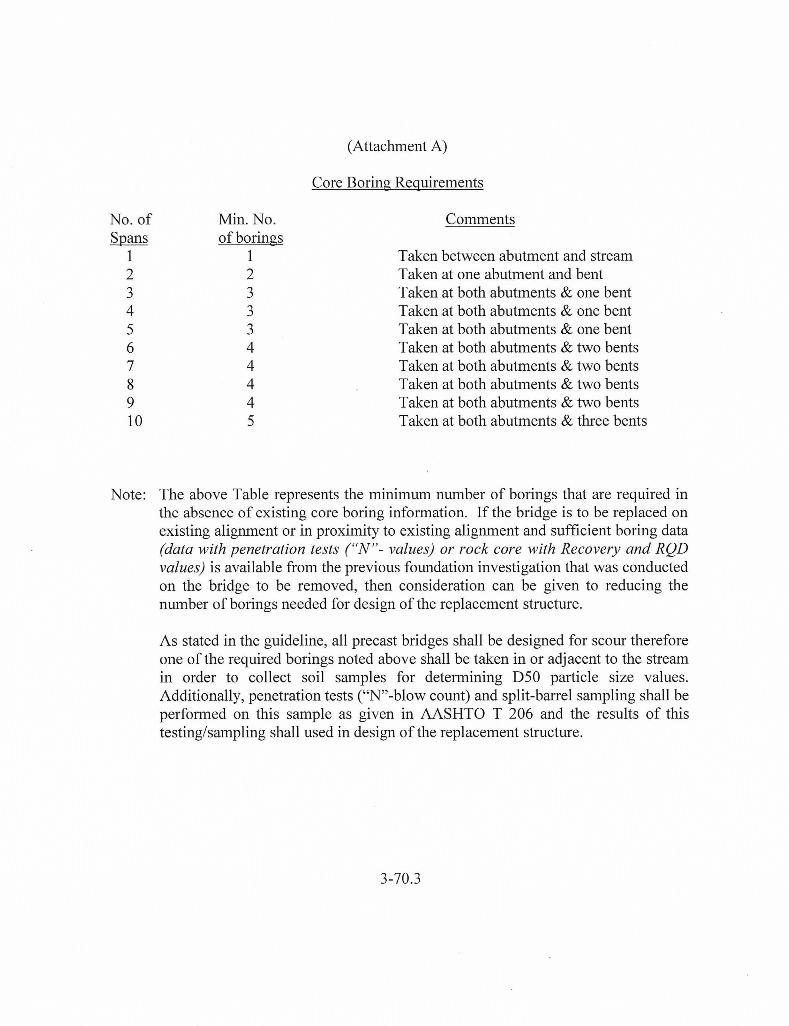
(Attachment A)
Core Boring Requirements
Comments
Taken between abutment and stream Taken at one abutment and bent Taken at both abutments & one bent Taken at both abutments & one bent Taken at both abutments & one bent Taken at both abutments & two bents Taken at both abutments & two bents Taken at both abutments & two bents Taken at both abutments & two bents Taken at both abutments & three bents
Note: The above Table represents the minimum number of borings that are required in the absence of existing core boring information. If the bridge is to be replaced on existing alignment or in proximity to existing alignment and sufficient boring data (data with penetration tests ("N "- values) or rock core with Recovery and RQD values) is available from the previous foundation investigation that was conducted on the bridge to be removed, then consideration can be given to reducing the number of borings needed for design of the replacement structure.
As stated in the guideline, all precast bridges shall be designed for scour therefore one of the required borings noted above shall be taken in or adjacent to the stream in order to collect soil samples for determining D50 particle size values. Additionally, penetration tests ("N"-blow count) and split-barrel sampling shall be performed on this sample as given in AASHTO T 206 and the results of this testing/sampling shall used in design of the replacement structure.
3-70.3

The Alabama Department of Transportation
ALDOT Guidance for Preconstruction Activities Procedure 398
Procedure for Conducting Subsurface Investigation and Foundation Reports
Bureau of Materials and Tests Geotechnical Section
Revised February 8, 2005
ATTACHMENT #3

ALDOT – 398 Revised-February 8, 2005
Page 2 of 17
TABLE OF CONTENTS
I. General Project Data 3
II. Bridge Foundations 4
III. Bridge Culverts 7
IV. Retaining Walls 8
V. Landslides 10
VI. Slope Studies 11
VII. Mine Studies 13
VIII. Soft Soils 13
IX. Reports 14
X. Referenced Documents 16
NOTES:
• For purposes of this document, the term “Engineer” shall refer either to theGeotechnical Engineer or the Consultant hired to perform the work for theGeotechnical Engineer.
• For County Bridge Bond projects, the terms Geotechnical Section andGeotechnical Engineer shall refer to the respective county engineer.
• For county bridges with span lengths of 41’ or less, the Engineer is referredto the March 20, 2001 memo entitled “Guidelines for Use in DevelopingCounty Bridge Project Plans” as produced by the County TransportationBureau Chief. Particular attention should be paid to the guideline foroperation at the back of the package entitled, “Policy for FoundationInvestigations for County Bridges with Span Lengths of 41 feet or Less UsingPile Bent Construction”.
• Should the plan assembly be metric, the Engineer shall complete allcalculations in metric and write the final report using metric units.

ALDOT – 398 Revised-February 8, 2005
Page 3 of 17
I. General Project Data
A plan and profile layout of the project site with planned fill heights and design flood elevations will be forwarded to the Engineer. The Engineer, using standard and accepted geologic and geotechnical engineering practices, shall investigate the site shown on the map included with the plan and profile layout. The Engineer shall conduct a geotechnical investigation, which includes all surveying, drilling, sampling, and laboratory testing, unless otherwise notified in writing. The Engineer shall use this data for the design calculations and foundation recommendations for the requested foundation report for the given structure.
The Engineer shall first conduct a reconnaissance of the site to determine any special characteristics, which could impact their plan of investigation. The Engineer shall also conduct a historical review of the site by reviewing geologic journals, available well logs, aerial photographs, construction logs and performance history of nearby existing structures or other similar documents to determine general geologic conditions that may exist in this area which could affect the project. In particular, the Engineer shall note geologic or man-made hazards such as limestone formations that could lead to sink hole development, underground mines, fault areas, etc., that could impact the project. The Engineer will also check with Bridge Bureau, Construction Bureau, Division Bridge Inspector, Maintenance Bureau (for Underwater Inspection Reports/Videos), District Engineer, and/or County Engineer as well as Materials & Tests Bureau files for the existence of any historical data including boring logs, foundation report, and pile driving records. The Engineer will document whom they contacted in each office and the results of that contact in the cost proposal.
After conducting the site reconnaissance, historical search, and review of the planned project, the Engineer shall submit an investigation plan which contains the boring pattern layout, proposed boring depth, boring method, sampling frequency and collection method, timetable for completion of the investigation, and any other information deemed pertinent. The investigation plan shall conform to the guidelines of this document and AASHTO R-13: Conducting Geotechnical Subsurface Investigation. The Engineer will specify all testing, with justification, that will be performed on the soils and the frequency with which such tests shall be conducted. The Geotechnical Engineer shall review the number and approximate location of borings and proposed testing. After negotiation of the work effort, a letter of formal approval of the cost estimate and work plan will be forwarded by the Materials & Tests Engineer.
Before initiation of the field work, the Engineer must determine if more than one acre of soil disturbance will be required in order to perform the work. Should the sum of all field disturbances exceed an acre or should the project site be located in the vicinity of a Tier 1 waterway as defined by ADEM Phase II Stormwater Regulations, a stormwater permit per ADEM regulations will be required. The Engineer shall prepare all pertinent applications and documentation for a stormwater permit and submit that information along with the appropriate fees to ADEM. Once approval of the stormwater permit is received, field work can commence. It shall be the responsibility of the Engineer to

ALDOT – 398 Revised-February 8, 2005
Page 4 of 17
perform all site inspections required to maintain the stormwater permit in good standing and to terminate the permit once field work is complete.
The Engineer shall insure that accurate and professional boring logs are maintained at all times, accurately depicting soil conditions encountered during drilling. All borings shall be performed in general accordance with AASHTO T-306: Progressing Auger Borings for Geotechnical Explorations and coring operations shall generally conform to AASHTO T-225. All borings will be surveyed in the field to within 0.3ft in station and offset and to within 0.1ft in elevation of their true locations and elevations, wherever possible. Station numbers and offsets shall be recorded in the log for each boring, as well as GPS Latitude and Longitude coordinates. In no case shall the test boring location be located >10 linear feet from the planned boring location without prior approval. All borings should be plotted on mylar, as outlined below in Section IX, Reports, and transmitted to the Geotechnical Engineer for inclusion in the final plan assembly. All borings shall have standard penetration tests per AASHTO T-206 taken at regular intervals throughout the length of the soil boring, and must show the water table level, if encountered. The water table elevation must be recorded in the log at the time of drilling and also at least 24 hours after the hole is completed, if possible. After a hole has been drilled, a temporary standpipe piezometer per AASHTO T-252 should be installed to full depth in selected borings, which are evenly spaced in the boring layout. In low permeability soils or rock, the static water level may have to be determined after a week or more. If artesian water conditions are encountered during the course of the investigation, a note should be placed on the boring logs along with an estimate of the pressure head and/or rate of flow. If the Engineer has another method that can be used to verify depth to groundwater in lieu of piezometers, then a request can be made, prior to implementation, for approval by the Geotechnical Engineer.
Using the results of the driller’s boring logs, the Engineer shall evaluate said data using appropriate engineering tools and judgement to determine the most appropriate foundation design for this project in conjunction with the designer. The Engineer shall evaluate various alternative foundation types if dictated by site specific conditions such as span arrangements, geology, etc.
II. Bridge Foundations
A. GENERAL
In the evaluation of the data gathered above, the Engineer shall consider the use of spread footings, pile footings, pile bents, and drilled shafts for foundation support as a minimum.
Borings: Typically, one boring per substructure unit should be taken to determine the site soil stratigraphy. If the use of drilled shafts is anticipated, the Engineer should plan to perform a boring for each planned drilled shaft location. Borings should be advanced through unsuitable materials into competent material for bearing capacity support. If

ALDOT – 398 Revised-February 8, 2005
Page 5 of 17
drilled shafts are anticipated and rock is encountered, borings should be extended at least 20 feet into the underlying bedrock. If artesian flow is encountered while investigating for deep foundations, the foundations must be designed to take into account the projected loss of skin friction due to the artesian water flowing up around the foundation. The Engineer shall use the following as guidance for their design recommendations: Corrosion Potential: The Engineer shall collect representative samples from ground and/or surface water encountered at the bridge site and analyzes the samples for sulfates, chlorides, resistivity and pH for the purpose of determining the appropriate pile or concrete type (steel or concrete piles or steel encased by concrete). Based on this data the Engineer shall recommend drilled shaft mix type 1, 2, or 3, pre-stressed pile concrete type PPM-02, or type AF-1a substructure concrete in corrosive environments. Scour Analysis: Where applicable, the Engineer shall provide soil D50 values to the ALDOT, which shall be used for scour analysis calculations. Using the D50 soil analysis data, the ALDOT shall provide the Engineer the scour estimate. Should the situation occur that the foundation is to be founded in rock, the Engineer, after consultation with the Geotechnical Engineer, may assume no formal scour analysis is required and thus the scour limit is the top of the rock. This assumption and its basis shall be included in the report. The Engineer shall evaluate the foundation alternatives using this scour estimate to calculate the minimum tip elevations at each selected foundation. B. PILE FOUNDATIONS (Pile footings and Pile bents) 1. The Engineer shall use a safety factor of 2.0 with respect to full axial loading. The
Engineer shall apply a safety factor of 1.2 for design of pile lengths for the estimated Q100 scour, (minimum tip elevation). Tip elevations shall also be checked for the Q500 scour. The Bridge Bureau will specify, usually on the bridge layout sheet, the design load to be used in the design calculations. In highly corrosive areas such as Mobile and Baldwin Counties, the Engineer shall evaluate the use of concrete piles.
2. The final foundation report should recommend the type of pile and reasons for the choice and/or exclusion of any pile types.
3. If difficult driving is anticipated, this should be noted in the foundation report along with the need for any pre-drilling or pile driving shoes.
C. SPREAD FOOTINGS 1. The Engineer shall determine the required depth for the bottom of the footing and
provide a reason for the recommendation. Spread footings are not generally considered economical at depths greater than 10 feet.
2. The Engineer shall determine the ultimate bearing capacity (qu) of the soil at the bottom of footing depth and recommend the safe allowable bearing capacity (qa) with a safety factor of 3.0, i.e., qa=qu/3.0.

ALDOT – 398 Revised-February 8, 2005
Page 6 of 17
3. The Engineer will discuss the need for dewatering, sheeting or shoring, and other construction considerations. This discussion will include a detailed description of the founding material so that the project inspector can verify the material is, as expected.
4. The Engineer will provide an estimate of the footing settlement and time rate of settlement. If significant settlement is expected, the Engineer shall recommend a method to decrease the amount of settlement.
D. DRILLED SHAFTS 1. The Bridge Bureau will specify, usually on the bridge layout sheet, the design load to
be used in the design calculations. The Engineer shall provide the Geotechnical Engineer with required depth for estimated tip elevations (safety factor of 3.0), minimum tip elevation for the estimated Q100 scour, (safety factor of 1.5). Tip elevations shall also be checked for the Q500 scour. These tip elevations should be set such that excessive settlement will not occur under the design load. Settlement calculations shall be performed per Appendix C of the FHWA Drilled Shaft manual. Excessive settlement will be defined as settlement which exceeds the tolerable total settlement and/or differential settlement for the particular superstructure as defined by the bridge designer. If the Bridge Bureau does not indicate a design load and size, the Engineer shall provide a range of sizes and allowable bearing capacities commensurate with the height and span length of the given bridge.
2. The Engineer shall make recommendations on the need for permanent casing and the depth for casing, if required. Casing should be self-supporting using skin friction alone with a safety factor of 1.5.
3. Suggestions of probable method of construction, whether the shaft may be cast using slurry, temporary or permanent casing or in the dry shall be included in the foundation recommendations. These suggestions shall not be statements of fact and shall contain caveats stating the suggestions are based upon interpreted site conditions.
4. If the drilled shaft will have a rock socket, the socket shall be one diameter into competent rock. Lateral analysis is the responsibility of the Bridge Bureau
5. The Engineer shall indicate whether probe/boring/core holes are required at planned tip elevation to verify subsurface conditions. Please specify which type of hole is needed, if any, and the number of holes required per shaft, if more than one is needed, a minimum depth of these holes. Please indicate in the foundation report if the holes need to be deeper than ten feet with supporting justification.
6. Should the Engineer recommend drilled shafts, the Engineer shall be prepared to evaluate and make recommendations on data collected from the cross hole sonic logging report, if required by the wet method of construction.
7. If coring is required to verify the cross-hole sonic logging results, the Engineer shall be prepared to evaluate and make recommendations on the cores collected.
E. REPORT The Engineer shall provide the Geotechnical Section, with a foundation report as outlined in Section IX. The final foundation report shall also include the following information:

ALDOT – 398 Revised-February 8, 2005
Page 7 of 17
1. Most suitable foundation type with justification2. Where feasible, foundation alternates3. Method of foundation support (end bearing, skin friction or combination)4. Foundation tip elevations to include range of variations in length, with scour
considerations take into account5. Software used in the design and/or sample calculations6. Settlement considerations to include down drag and/or surcharging of the fill7. Discussion of pile drivability, with particular attention paid to underlying soft soils
and/or boulders8. LPILE data for use by Bridge Bureau in determining the lateral load capacity of the
pile or shaft9. Advisability of using test piles to include best location of test piles to obtain
maximum information regarding length and driving stress considerations10. Recommendation on load tests to include location and test methods and procedures if
the test methods and procedures are different from those specified in the ALDOT’sStandard Specifications for Highway Construction
11. Effect of pile driving on adjacent structures12. Recommended elevations for base of spread and pile footings13. Evaluation of the safe allowable design loads giving full consideration to the bearing,
time-settlement relationships14. Evaluation of approach embankments by considering settlement of embankments due
to consolidation of sub-soil foundations, densification within the embankment,embankment stability, abutment rotation and horizontal component of verticalsettlement of approach embankments
15. Precautions that should be taken to reduce the possibility of damage to the structurecaused by activities associated with the approach embankment
16. Where applicable, recommendations on ways to accelerate drainage/settlement byevaluating items such as wick drains, surcharging, etc. The Engineer shall determinethe impact this activity may have on adjacent structures and streams
III. Bridge Culverts
A. DEFINITION
Bridge culverts are defined as culverts where the length of the culvert along centerline will equal or exceed 20 feet.
B. GUIDANCE
If drainage sections are not available and transmitted at the time of the request, use the tables Earth Slopes Horizontal to Vertical for Types of Terrain, found in Notes 106, 107 and/or 108 of the ALDOT Special Drawing No. GN-2 in conjunction with the applicable “typical roadway section” and planned roadway profile to establish the probable inlet and outlet locations of the culvert.

ALDOT – 398 Revised-February 8, 2005
Page 8 of 17
1. Culverts having a length of 300 feet or less should be drilled at mid-length and at each end.
2. Culverts exceeding 300 feet in length should be drilled so that the distance between inlet and outlet borings is equally divided into approximately 150 linear foot increments.
C. BORINGS 1. Extend borings to a depth of 1.5 times the expected fill height, a minimum of ten
vertical feet, or ten vertical feet into competent material, whichever occurs first. 2. Sufficient undisturbed samples (AASHTO T-207) should be recovered and tested to
permit calculation of the soil bearing capacity and expected settlement of the assumed culvert(s) as outlined in FHWA publication NHI-00-045 Soils & Foundations, Chapter 6.
3. Should soft soils be encountered, such that the execution of borings is prohibited, “soundings” should be performed to determine the depth and lateral extent of the soft soils, as outlined in Section VIII of this document.
D. REPORT A brief foundation report should be prepared for each investigated culvert location. The report shall include: 1. Expected site soil profile(s) 2. Results of soil bearing capacity calculations 3. Estimated settlement with analyses 4. The Engineer’s recommendations for subgrade improvement(s) should the available
bearing capacity appear to be inadequate and/or excessive differential settlement is anticipated.
IV. Retaining Walls A. GENERAL 1. The Engineer will receive the plan, profile and cross-sections for the proposed wall
location. The plans may or may not indicate whether the wall is to be cast-in-place (CIP), mechanically stabilized earth (MSE), etc. If the wall type is not specified, the Engineer should recommend the type wall to be used with supporting data or recommend the final plans contain alternates if several types are equally viable. Generally, the wall type selection should be left to the contractor, if at all possible.
2. Using the information provided, the Engineer should plan an appropriate number of boring and sampling locations to adequately determine the soil stratification beneath the proposed wall. Typically, borings should be placed every 100 to 200 feet along the length of the wall, and should extend to a depth of twice the wall height or ten feet into competent material, whichever occurs first.
3. Design of the actual wall elements will be the responsibility of the wall designer.

ALDOT – 398 Revised-February 8, 2005
Page 9 of 17
B. ENGINEER’S RESPONSIBILITIES 1. Provide the allowable bearing capacity 2. Check the factors of safety for all phases of global stability
a. Sliding, (FS=1.5) b. Overturning, (FS=2.0) c. External slope stability (FS=1.5), i.e., rotational failure beneath the wall. d. Stability of the construction excavation, (FS=1.2).
3. If soft soils are encountered such that bearing capacity for the height of wall specified is of concern, the Engineer will recommend a method of remediation. Recommendations may include but are not limited to: a. undercut and backfill b. founding of the footing on deep foundations c. stone columns d. proprietary options
4. The recommendations should contain the depth of undercut and specifications on the type of backfill to use per ALDOT Standard Specifications for Highway Construction. For further guidance on investigations in soft soils, please refer to Section VIII, Soft Soils.
5. The foundation report shall indicate an estimate of the total settlement, differential settlement, and time rate of settlement. The report shall also indicate if the type wall chosen will allow for the differential settlement and/or recommend alternatives.
6. Should site characteristics indicate the use of other types of retaining structures such as rock bolts, soil nails, tiebacks, gabions, or shotcrete surfacing, the Engineer will be required to write and/or review pertinent special provisions to the ALDOT Standard Specifications for Highway Construction. Special attention should be paid to the location of the ROW line as it pertains to rock bolts, soil nails, and tiebacks.
C. REPORT 1. The foundation report for retaining walls shall follow the guidelines outlined in
Section IX, Reports. 2. The Engineer shall provide a drawing, suitable for inclusion in the plans, with the
“wall envelope” shown. The wall envelope includes: a. A profile view of the wall with the top of wall, bottom of wall, bottom of footing,
and begin and end stations clearly indicated. b. The bearing capacity along the length of the wall, particularly if the bearing
capacity changes along the length of the wall. c. The limits (length and depth) of undercut and backfill or locations for other soil
remediation which may be necessary beneath the wall. 3. The foundation report shall also cover any construction details such as dewatering,
sheeting, shoring, etc. 4. The lateral earth pressures, which will be exerted on the wall, shall also be provided
so that the wall designer can account for these loads during the design phase.

ALDOT – 398 Revised-February 8, 2005
Page 10 of 17
5. If special, site specific, drainage details are needed; these shall also be covered in thefinal foundation report.
V. Landslides
A. PROJECT INFORMATION
1. For any landslide remediation request, the Engineer will receive a location andvicinity map along with cross-sections of the landslide, if available at the time of therequest.
2. The Engineer shall be expected to contact the ALDOT District Engineer and/orCounty Engineer to ascertain the maintenance history of the slide area, to include anyprevious corrective measures taken.
3. Once a site reconnaissance has been completed, the Engineer will propose aninvestigation plan including boring and instrumentation locations with rationale foreach sampling and testing location. If the use of slope inclinometers is proposed, theinstallation, monitoring and processing of the data shall conform to the guidelines inAASHTO T-254.
4. Once the Geotechnical Engineer has approved the investigation plan, the Engineershall proceed with the investigation phase.
B. DATA ANALYSIS
1. Perform field work per approved investigation plan2. Perform laboratory analyses3. Utilize design software to prepare a remediation procedure
C. REPORT
Once the Engineer has gathered, reviewed and analyzed all pertinent data, the Engineer shall provide a foundation report outlining the proposed remediation procedure. This foundation report shall include, but is not limited to, the following: 1. Site soil profile cross-section used for analysis2. Site plan indicating length, ground surface cracks, head scarp, toe bulge and general
location of slide, along with any springs emitting from the face of the slide3. Detailed narrative history of the slide area, including movement history, maintenance
work, and previous corrective measures4. Assumed or back calculated soil strength parameters and probable slide failure plane5. Proposed remediation technique with cross-section drawn to a reasonable scale and
showing dimensions with an estimated safety factor (>1.3 or >1.5 if a structure isinvolved), estimated cost, advantages and disadvantages. Remediation techniquesmay include but is not limited to :
a. Rock buttressb. Shear keyc. Rebuild slope

ALDOT – 398 Revised-February 8, 2005
Page 11 of 17
d. Surface drainage e. Subsurface drainage-interceptor f. Drain trenches g. Horizontal drains h. Retaining structures
6. Construction sequence and factor of safety for excavated slope during construction. 7. If special construction techniques or materials are to be used, the Engineer will write and/or review all special provisions related to the special construction techniques or materials. The Engineer shall also indicate what types of material to use for regular construction techniques and any gradation and/or compaction requirements, per ALDOT Standard Specifications for Highway Construction. VI. Slope Studies A. RECEIVE PROJECT INFORMATION Which will include but is not limited to:
• General Roadway Alignment • Plan & Profile of project, • Cross sections of project
B. DETERMINE BORING LOCATIONS AND DEPTHS 1. Borings should typically be spaced every 200 feet to 500 feet along centerline 2. At least one boring should be taken in each separate landform. 3. Borings shall be taken in the left and right ditch lines, extending approximately 3 feet
below the ditch line, in order to establish a geologic cross-section for analysis. 4. For large cuts, the geologic cross-sections should be taken at approximately the
quarter points of the cut or where considered most effective. 5. Borings in fill areas should be extended to 1.5 times the proposed fill height or to
augur refusal, whichever is shallowest, but no more than 10 feet into competent material. A limited amount of coring should be completed to ensure augur refusal did not occur on a boulder. If boulders are encountered, borings should be extended until true, competent is reached.
6. If soft soils are encountered, follow the guidelines under Section VIII, Soft Soils, below.
C. PERFORM FIELD WORK Once the Geotechnical Section has approved the boring location plan, the Engineer can proceed with the boring and sampling phase of the project. The information obtained during this phase of the project will be used by the Engineer and their Geologist to determine the appropriate slopes. Borings shall be plotted on cross-sections in order to provide site soil profiles through the cuts and fills.

ALDOT – 398 Revised-February 8, 2005
Page 12 of 17
If caves, sinkholes, and/or karst features are encountered on the project, the following steps should be included in the investigation process:
• Perform site inspection of the cave itself • Determine the exact location of the feature to include elevations • Gather historical data from Speological Society • Determine the impact of the proposed roadway construction on the feature • Determine if sink hole activity is current or dormant • Obtain a copy of the sink hole map for the county • Overlay the sinkhole/cave/karst feature on the project alignment maps
D. REPORT A slope study report shall be produced by the Engineer which includes the following items:
1. A table giving slope recommendations by station, left and right of centerline throughout the length of the project, with references to the figures associated with each station. Slope recommendations should be for the steepest slope that can be utilized and still remain stable.
2. Typical sections for each slope cross-section configuration, e.g. rock cuts and soil cuts.
3. Profiles along each cut as viewed from the centerline which graphically indicates the following:
a. approximate top of cut, b. ditch line, c. zone of weathered rock and/or soil with slope recommendation, d. approximate top of rock cut, e. zone of rock cut with slope recommendations f. bench locations. g. These profiles should cover each cut section from station to station, and
indicate the stations covered and approximate elevations. 4. If cuts are located on both sides of the projected roadway at any station, then two
profiles, one right and one left of centerline will be required. 5. Discussion of any evidence of springs and excessively wet areas, along with a
general note regarding the surface and subsurface drainage observed. 6. If slides, slumps, and faults are noted during the course of the investigation, these
should be discussed along with measures to prevent problems in the future. 7. If soil cut slopes are included on the project, a formal stability analysis may be
required in order to determine if the proposed slope has a sufficient factor of safety against failure
8. If any of the soil or rock materials encountered in the cuts are not suitable for reuse on the project, a plan note should be included detailing the station to station location and elevations of the unsuitable material.
9. Recommendations on the need for blasting for rock cuts and an evaluation of the effects of blast induced vibrations on adjacent structures.
10. Recommendations on the need for special rock slope stabilization measures such as rock fall catch ditch, wire mesh slope protection, shotcrete, rock bolts, etc.

ALDOT – 398 Revised-February 8, 2005
Page 13 of 17
11. Recommendations on the slope angle to use in fill areas. 12. Maps indicating the location of any caves/sinkholes/karst features encountered on
the project and recommendations to minimize impacts from said features. VII. Mine Studies In order to determine if a mining operation may impact the project area, the Engineer/Geologist shall conduct the following activities:
1. Evaluate the need for study: Make an initial evaluation of the study area by reviewing available topographic maps and regional geology to determine the possibility of underground or strip mines.
2. Historical research: After confirming the need to complete a study, the Engineer/Geologist shall conduct a detailed literature search to determine the possible locations, type, and extent of mining activities.
3. Agency search: The Engineer/Geologist shall visit the Mine Safety and Inspection Office, the Surface Mining Commission, the Alabama Geological Survey, other government offices or commercial facilities, such as USX, in order to find detailed maps and records of mining activity.
4. Field reconnaissance: The Engineer/Geologist shall walk the project area to evaluate potential impact of the suspected mining activity on the construction project.
5. Drilling confirmation: The Engineer/Geologist shall attempt to locate any suspected mines by using slope study drilling, soil profile drilling or additional drilling.
6. Present findings: The Engineer/Geologist shall submit a written report of their findings to include the mine location, type of mine, material mined, approximate mine depths, approximate mine alignment in relation to the proposed road way layout, potential impact on the road and construction, recommended method of treatment, if needed, and any other information that the Engineer/Geologist deems appropriate.
VIII. Soft Soils A. If during the course of an investigation, the Engineer encounters areas of muck,
unsuitable material, and/or soft soils, further investigation and analysis of the area shall be performed.
B. Where unsuitable material and/or muck is encountered, soundings or boring and sampling shall be taken along the centerline and right and left of centerline out to the limits of construction to determine the depth and extent of the unsuitable material and/or muck. Recommendations shall be made for removal and/or treatment of any unsuitable material and/or muck encountered.
C. In the case of soft soils, particularly those located beneath a proposed embankment, the stability and settlement of the fill must be carefully evaluated.

ALDOT – 398 Revised-February 8, 2005
Page 14 of 17
1. The factor of safety for stability of the embankment must be equal to or greaterthan 1.3 or 1.5 if a structure is involved.
2. If the soft soils preclude the embankment from meeting this criterion, theEngineer shall provide recommendations for treatment of the soft soils.Treatment options may include but are not limited to:a. change of alignment,b. change of grade,c. use of stabilizing counter berms,d. excavation and replacement of weak subsoil,e. staged construction with/without surcharging and/or wick drains,f. lightweight fill,g. geosynthetic reinforcement, etc.
3. The Engineer shall also provide cost comparisons and advantages anddisadvantages for the various treatment alternatives given.
4. Recommend the best alternate for the site, taking into account cost, timeliness,and safety.
D. The consolidation properties of the soft soils should be determined through laboratory testing so that an estimate of the amount of settlement and the time rate of settlement can be determined. 1. The Engineer shall provide an estimate of the delay time for the contractor due to
settlement.2. If instrumentation will be required to monitor the fill stability and/or settlement,
the specific location of the device(s) should be indicated in the report.3. The Engineer will also be responsible for developing and/or reviewing any special
provisions which are required for the instrumentation.
E. If excavation and replacement is the recommended option for remediating the soft soils, the Engineer shall provide mylar drawings indicating the vertical and lateral limits of the excavation.
F. If a surcharge program is recommended, the Engineer shall provide mylar plan and cross-section views of the treatment plan along with a recommendation of where to dispose of the surcharge material once settlement is complete.
IX. Reports
A. The final foundation report provided by the Engineer shall include the following items as a minimum:
1. A brief description of the field work to include such information/data as when andwho performed the work, site conditions at time work was performed, scope andpurpose of the investigation,
2. Brief description of in place structures to include foundation type, design load,pile tips, etc., the structure’s performance, and a copy of any boring logs anddriving records found during the historical search ,

ALDOT – 398 Revised-February 8, 2005
Page 15 of 17
3. A general description of subsurface soil, rock, and groundwater conditions,4. A geologic and physiographic description of the site to include location, geologic,
and topographic maps,5. Boring logs, boring location plan, field test data, summary of laboratory test data,
and subsurface profile with word descriptions of the various soil and rock typesalong with abbreviated boring logs and water levels indicated
6. Graphical and/or tabular information obtained through field soft soil soundings7. Specific engineering recommendations for design based upon the soil features
encountered at the site, to include:a. A listing of assumptions used in producing the report and recommendations,b. A description of software used in evaluating the various design alternatives,c. A thorough discussion of groundwater conditions at the site, to include
artesian conditions, if present, and impacts it may have on the project.8. A discussion of construction considerations to include:
a. Groundwater impacts on construction such as fluctuations in height of groundor surface water, control in excavations, well points, pumping, tremie seals,etc.
b. Adjacent structures and any damage that may result from excavation, piledriving, blasting, drainage, etc.
c. Evaluation of pile driving to include difficulties or unusual conditions whichmay be encountered (i.e. hard driving), special precautions which may berequired, special equipment, pile driving sequence
d. Excavation to include control of earth slopes, types of material to beencountered, and the need for a cofferdam or sheeting and shoring.
e. A sequence of construction for landslides and other special constructionsituations. The sequence of construction shall include but is not limited torecommended lengths for open excavations, placement of fill on specializedareas, recommended location to start construction (i.e., start downhill onexcavations so as not to create drainage problems), and any other instructionas deemed pertinent.
B. The Engineer will submit a draft copy of the foundation report for review by the Geotechnical Section. Along with the draft, the Engineer will submit a completed copy of the FHWA document “Checklists and Guidelines for Review of Geotechnical Reports and Preliminary Plans and Specifications”. Once the Geotechnical Section has returned comments, the Engineer will finalize the report and submit ten (10) copies of the final report to the Geotechnical Section for distribution.
C. BORING LOGS
1. A 24”x36” plan sheet depicting boring logs (mylar) produced by the GeotechnicalSection has been forwarded to the Engineer and should be the basis for the soildisplay used by the Engineer.
2. The Engineer shall prepare 24”x36” mylars depicting the boring information forinclusion in the final plan assembly. These boring logs shall be easily readablewhen produced as half-scale, quarter size prints and/or 11”x17” plots. The

ALDOT – 398 Revised-February 8, 2005
Page 16 of 17
appropriate font types and sizes as well as line weights for use in microstation are available on the ALDOT website under the Design Bureau.
3. All boring logs shall indicate the water level in the boring, depth to caving, if thehole caved in, and/or no water table encountered.
4. The boring log shall also indicate the make and model of the drill rig, method ofdrilling and/or coring, and the type of hammer used for SPT sampling.
5. A note should be placed on the boring log sheet indicating where the cores takenon the project, if any, will be stored.
a. Core shall be taken to the nearest district or division office to the projectsite and stored for review by potential contractors.
b. The boxes shall be labeled with the ALDOT project number on all foursides of the boxes.
c. The top of the box shall be labeled with the box number, boring number,hole depth, elevations, station number, and county.
6. All borings shall be identified sequentially referencing station numbers, offsetsand bent/abutment/pier numbers as designated on the bridge layout.
7. If soft soil “soundings” were obtained on the project, a graphical interpretation ofthis information should also be placed on mylar for inclusion in the final planassembly.
8. The Engineer can propose a different boring log product for review at time ofboring layout submittal as long as said proposal is accepted by the GeotechnicalEngineer, prior to initiation of the work.
X. Referenced Documents
• AASHTO T-206: Penetration Test and Split-Barrel Sampling of Soils• AASHTO T-207: Thin-Walled Tube Sampling of Soils• AASHTO T-225: Diamond Core Drilling for Site Investigation• AASHTO T-252: Measurements of Pore Pressures in Soils• AASHTO T-254: Installing, Monitoring, and Processing Data of the Traveling
Type Slope Inclinometer• AASHTO T-306: Progressing Auger Borings for Geotechnical Explorations• AASHTO R-13: Conducting Geotechnical Subsurface Investigations• ALDOT Special Drawing No. GN-2• FHWA Publication NHI-00-045 Soils & Foundations• ALDOT Standard Specifications for Highway Construction• FHWA Drilled Shafts: Construction Procedures & Design Methods• FHWA Checklists & Guidelines for Review of Geotechnical Reports &
Preliminary Plans & Specifications• ADEM Phase II Stormwater Regulations

ALDOT – 398 Revised-February 8, 2005
Page 17 of 17
REVISIONS
Revision #
1
2
3
Subject
Change of Title & Added Front Cover
Changed Title; Added historical checklist; Added items for inclusion on boring logs; Added settlement criteria for drilled shafts; Referenced the County Trans. Memo; Requested draft copy for review and 10 final copies
Added sections for Bridge Culverts, Retaining Walls, Landslides, Slope Studies, Mine Studies, and Soft Soils
Date
September 21, 1999
May 2, 2001
February 8, 2005