Embed Size (px)
DESCRIPTION
ambil laa
Citation preview

UNIVERSITI TEKNOLOGI MARAFAKULTI KEJURUTERAAN KIMIA
CHEMICAL ENGINEERING LABORATORY II( CHE 523 )
NAME : MOHAMAD ARIF BIN MUSA
STUDENT NO : 2008297884GROUP : EH2203DEXPERIMENT : FREE AND FORCED VORTEX (LAB3) DATE PERFORMED : 19th AUGUST 2009SEMESTER : 3PROGRAMME / CODE : EH220SUBMIT TO : PN. SYAFIZA ABD HASHIB
No. Title Allocated Marks % Marks1 Abstract / Summary 52 Introduction 53 Aims / Objectives 54 Theory 55 Apparatus 56 Methodology/Procedures 107 Results 108 Calculations 109 Discussion 2010 Conclusion 1011 Recommendations 512 References 513 Appendices 514 Attendance ( Hands-on works )
100
Remarks :
Checked by : ---------------------------Date
TOTAL MARKS

TABLE OF CONTENT
ABSTRACT…………………………………………………………..3
INTRODUCTION………………………………………………….4
OBJECTIVE………………………………………………………....5
THEORY……………………………………………………………...5
APPARATUS……………………………………………………….8
PROCEDURE……………………………………………………….8
RESULT……………………………………………………………...9
CALCULATION…………………………………………………...9
DISCUSSION……………………………………………………...15
CONCLUSION…………………………………………………….17
RECOMMENDATION…………………………………………18
REFERENCE……………………………………………………….19
APPENDICE………………………………………………………..20

ABSTRACT
The aim of this experiment is to determine the surface profile of a forced vortex and also to
investigate the physical phenomena associated with a free vortex. Vortex is a whirling mass of water or
air in which a force of suction operates, as a whirlpool or in the form of a visible column or spiral, as a
tornado. Vortex motion usually describes motions in a frictionless fluid. In such cases, the absence of
friction would make it impossible to create or to destroy vortex motion. In order to fulfil the objective of this
experiment, it has two kind of experiment was performed. Firstly for free vortex experiment, three different
size in diameter of arm pitot tube was used which are 15, 25 and 30 mm respectively. We made an
observation upon vortex that formed and found that small diameter of pitot tube created small vortex
whereas large diameter of orifice created larger vortex. The speed of circulation of vortex is slow,
moderate and fast depends on the size of pitot tube respectively. In the other hand, for the forced vortex
experiment, the revolution of the blade was calculated and the height of datum was computed and our
result was slightly different with the theoretical value. In the second part of this experiment, the propeller
was used to calculate the rotation as planned in procedure in order to find out the velocity head. After
that, the height of the datum was observed. By the end of this experiment, it is clearly stated that, the free
and force vortex had difference type of characteristic based on the way their created and factors that
affect their condition. The average velocity head, hc for the 10, 20, 30, 40, 50 and 60 revolutions in the
forced vortex experiment was determined to be 0.0350m, 0.0512m, 0.0710m, 0.0552m, 0.0428m and
0.0231m respectively.

INTRODUCTION
Fluid mechanics has developed as an analytical discipline from the application of the classical
laws of static, dynamics and thermodynamics, to situations in which fluids can be treated as continuous
media. The particular laws involved are those of the conservation of mass, energy and momentum and, in
each application, these laws may be simplified in an attempt to describe quantitatively the behavior of the
fluid. The hydraulics bench service module, F1-10, provide the necessary facilities to support a
comprehensive range of hydraulic models each of which is designed to demonstrate a particular aspect of
hydraulic theory. The Free and Forces Vortex Apparatus, F1-23 is the specific hydraulic model that we
are concerned with for this experiment.
In common usage, a fluid motion dominated by rotation about an isolated curved line in space, as
in a tornado, a whirlpool, a hurricane, or a similar natural phenomenon. The importance of vortices is due
to two characteristics: general fluid flows can be represented by a superposition of vortices; and vortices,
once created, have a persistence that increases as the effects of viscosity are reduced. The aerodynamic
lift forces and most other contributors to the forces and moments on aircraft and other bodies moving
through fluids do not exist in the absence of vortices. See also Aerodynamic force; Hurricane; Tornado;
Waterspout.
The strength of rotation is measured by a vector called the vorticity, ω, defined as the curl of the
velocity vector. A region of flow devoid of vorticity is known as irrotational. The spatial distribution of the
vorticity vector provides a precise characterization of the rotation effects in fluids, and the nature of what
subjectively and popularly would be called a vortex. See also Calculus of vectors; Laplace's irrotational
motion.
. A vortex is a spinning, often turbulent, flow (or any spiral motion) with closed streamlines. The
shape of media or mass swirling rapidly around a center forms a vortex. It flows in a circular motion. A
vortex can be seen in the spiraling motion of air or liquid around a center of rotation. Circular current of
water of conflicting tides form vortex shapes. Turbulent flow makes many vortices. A good example of a
vortex is the atmospheric phenomenon of a whirlwind or a tornado or dust devil. This whirling air mass
mostly takes the form of a helix, column, or spiral.

The rotation of a fluid, moving as a solid, about an axis is called forced vortex motion. Every particle of
fluid has the same angular velocity. This motion is to be distinguish from free vortex motion, where each
particles moves in a circular path with a speed varying inversely as the distance from the centre. The
centrifugal effect in a vortex throws heavy liquid/air out to the perimeter whilst lighter air or liquid are
pushed to the center. Electrically, the air polarized with negative ions or as electrons will be pushed to the
center and down, the air with positive ion content will move upward and outward.
Some of the important cases of forced vortexes are:
The movement of the liquids within the impeller of a centrifugal pump when there is no flow as, for
example, when the outlet valves are closed.
The rotation of the liquid within the confines of a stirrer in an agitated tank.
The rotation of liquids in the basket of centrifuge
Figure 1 : shows the example of force vortex formed
The discharge and the surrounding containment have to be regular in shape; otherwise more and
chaotic turbulences within the fluid accelerating through the discharge break the vortex symmetry and
hinder its progress. Regular does not mean a perfect cone, but a shape mimicking the structure of natural
turbulence. This shape is somewhat ropy walled parabolic cone as shown in the figure above.

OBJECTIVES
1. The main objective of this experiment is to determine the surface profile of a forced vortex.
2. Other goal of this experiment is to investigate the physical phenomena associated with a free
vortex.
THEORY
Based on the dictionary, vortex is a circular, spiral, or helical motion in a fluid (such as a gas) or
the fluid in such a motion. A vortex often forms around areas of low pressure and attracts the fluid (and
the objects moving within it) toward its center. Tornados are examples of vortexes; vortexes that form
around flying objects are a source of turbulence and drag. A vortex can be seen in the spiraling motion of
air or liquid around a center of rotation. Circular current of water of conflicting tides form vortex shapes.
Turbulent flow makes many vortices. A good example of a vortex is the atmospheric phenomenon of a
whirlwind or a tornado or dust devil. This whirling air mass mostly takes the form of a helix, column, or
spiral. Tornadoes develop from severe thunderstorms, usually spawned from squall lines and supercell
thunderstorms, though they sometimes happen as a result of a hurricane.
In the other hand, a vortex can be any circular or rotary flow that possesses vorticity. Vorticity is a
mathematical concept used in fluid dynamics. It can be related to the amount of "circulation" or "rotation"
in a fluid. In fluid dynamics, vorticity is the circulation per unit area at a point in the flow field. It is a vector
quantity, whose direction is (roughly speaking) along the axis of the swirl. Also in fluid dynamics, the
movement of a fluid can be said to be vortical if the fluid moves around in a circle, or in a helix, or if it
tends to spin around some axis. Such motion can also be called solenoidal. In the atmospheric sciences,
vorticity is a property that characterizes large-scale rotation of air masses. Since the atmospheric
circulation is nearly horizontal, the (3 dimensional) vorticity is nearly vertical, and it is common to use the
vertical component as a scalar vorticity. Mathematically, vorticity is defined as the curl of the fluid
velocity :

Free vortex
When water flows out of a vessel through a central hole in the base, a free vortex is formed. In a free
cylindrical vortex, the velocity varies inversely to the distance from the axis of rotation.
(1)
The equation governing the surface profile is derived from Bernoulli’s Theorem:
(2)
Thus, by substituting equation (1) into equation (2), it will give a new expression of equation
Which is the equation to a hyperbolic curve which is asymptotic to the axis of rotation and to the
horizontal through .
Forced vortex
For a constant speed of rotation,
Where = radius,
= velocity of flow at radius,
Then, head due to kinetic energy is equal to the velocity head,
Since this is a derivation from the Bernoulli’s theorem, the term of mass can be eliminated from above
equation.

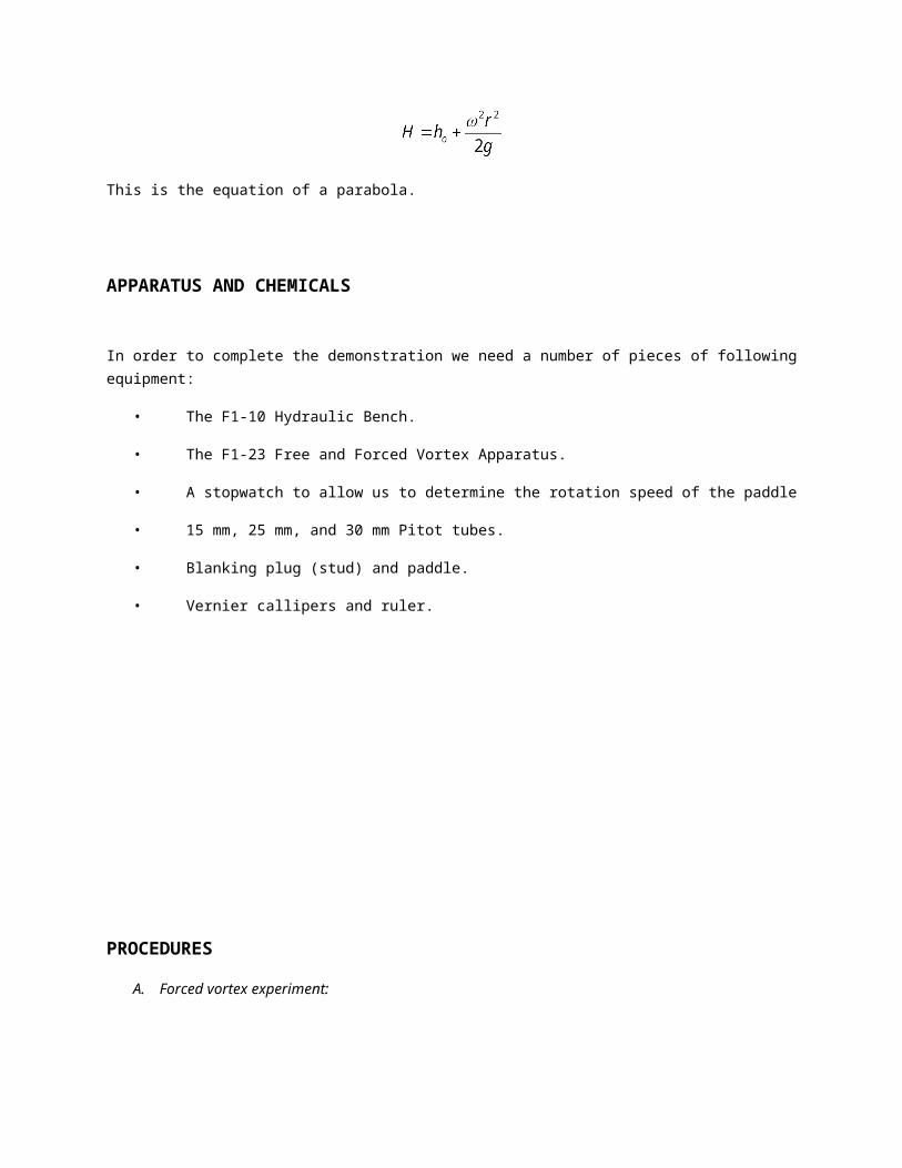
If the horizontal plane passing through the nadir (lowest point) of vortex is taken as datum, theory shows
that , substituted term :
This is the equation of a parabola.
APPARATUS AND CHEMICALS
In order to complete the demonstration we need a number of pieces of following equipment:
• The F1-10 Hydraulic Bench.
• The F1-23 Free and Forced Vortex Apparatus.
• A stopwatch to allow us to determine the rotation speed of the paddle
• 15 mm, 25 mm, and 30 mm Pitot tubes.
• Blanking plug (stud) and paddle.
• Vernier callipers and ruler.
PROCEDURES
A. Forced vortex experiment:

1) The apparatus was positioned into the working channel of the bench and the supply was
connected.
2) The blanking plug was placed into the central hole in the base of the cylinder. The paddle was
pressed onto the stud. A flexible hole was connected to the outlet pipe and the outlet valve was
closed.
3) The bench pump was switched on, the bench control valve and the three-way inlet valve was
opened so that water enters the cylinder from the 9 mm tangential inlet ports, set at 60 degrees,
and was leaves through the larger ports, discharging into this volumetric tank.
4) The outlet pipe was raising and it was allowed to fill with water, and then it was lowered into the
volumetric tank.
5) For each value of flow rate the outlet valve was adjusted until water just flows through the
overflow cutouts.
6) When the water level was maintained at the red scale/spot (designated on the profile) the bridge
was placed with the measuring needles across the top of the cylinder. The profile of the surface
was determined by lowering the measured needles until the just touch the water surface.
7) The speed of rotation of the paddle was measured by timing the revolutions number of paddle
rotations using the maker spot as a reference. The numbers of revolution are 10, 20, 30, 40, 50,
and 60 and the time for the paddle to complete each revolution was recorded.
8) The bridge was removed and the length of each needle was recorded.
B. Free Vortex experiment:
1) The apparatus was positioned into the working channel of the bench and the supply was
connected. An orifice was placed into the center hole in the base of the cylinder.
2) The bench pump was switched on, the bench control valve and the three-way inlet valve was
opened so that water enters the cylinder from the 12 mm diameter tangential inlet ports set at 150
degrees and was discharges through the orifice into the volumetric tank.
3) The profile-mid hole was implanted with the 15 mm radius pitot tube.
4) Pitot tube orifice was attached and immersed until the nose is at the core profile surface. The
water was allowed to flow and the water flow was maintained.
5) The diameter of the vortex was measuring and then the flow pattern of vortex was observed and
drawn on the paper.
6) The experiment was repeated with the 25 mm 30 mm pitot tube.
RESULTS AND CALCULATIONS

A. FREE VORTEX
Arm pitot diameter (mm)
Diameter of
the vortex (mm)Observations Surface profile
15.00 18.00Slow speed of circulation and small size of vortex
25.00 41.00Medium speed circulation with medium size of vortex
30.00 55.00Fast speed of circulation with big size of vortex
B. FORCED VORTEX
a) 10 number of revolution
Number of Time, t Revolutions Radius of Measured Height Calculated
revolutions, N
(s) per second, ω (rps)
measuring needles, r (m)
needles length, l (m)
from datum, hm
(m)
height, hc (m)
105.72 10.98
0.1100 0.1410 0.0530 0.07440.0900 0.1570 0.0370 0.04980.0700 0.1720 0.0220 0.03010.0500 0.1850 0.0090 0.01540.0300 0.1860 0.0080 0.00550.0000 0.1940 0.0000 0.0000
Average calculated height, hc 0.0350
b) 20 number of revolution
Number of revolutions, N
Time, t (s)
Revolutions per second, ω (rps)
Radius of measuring needles, r (m)
Measured needles length, l (m)
Height from datum, hm
(m)
Calculated height, hc (m)
209.47 13.27
0.1100 0.1410 0.0530 0.10860.0900 0.1570 0.0370 0.07270.0700 0.1720 0.0220 0.04400.0500 0.1850 0.0090 0.02240.0300 0.1860 0.0080 0.00810.0000 0.1940 0.0000 0.0000
Average calculated height, hc 0.0512
c) 30 number of revolution
Number of revolutions, N
Time, t (s)
Revolutions per second, ω (rps)
Radius of measuring needles, r (m)
Measured needles length, l (m)
Height from datum, hm
(m)
Calculated height, hc (m)
3012.06 15.63
0.1100 0.1410 0.0530 0.15070.0900 0.1570 0.0370 0.10090.0700 0.1720 0.0220 0.06100.0500 0.1850 0.0090 0.03110.0300 0.1860 0.0080 0.01120.0000 0.1940 0.0000 0.0000
Average calculated height, hc 0.0710
d) 40 number of revolution
Number of Time, t Revolutions Radius of Measured Height Calculated

revolutions, N
(s) per second, ω (rps)
measuring needles, r (m)
needles length, l (m)
from datum, hm
(m)
height, hc (m)
4018.22 13.79
0.1100 0.1410 0.0530 0.11730.0900 0.1570 0.0370 0.07850.0700 0.1720 0.0220 0.04750.0500 0.1850 0.0090 0.02420.0300 0.1860 0.0080 0.00870.0000 0.1940 0.0000 0.0000
Average calculated height, hc 0.0552
e) 50 number of revolution
Number of revolutions, N
Time, t (s)
Revolutions per second, ω (rps)
Radius of measuring needles, r (m)
Measured needles length, l (m)
Height from datum, hm
(m)
Calculated height, hc (m)
5025.87 12.14
0.1100 0.1410 0.0530 0.09090.0900 0.1570 0.0370 0.06080.0700 0.1720 0.0220 0.03680.0500 0.1850 0.0090 0.01880.0300 0.1860 0.0080 0.00680.0000 0.1940 0.0000 0.0000
Average calculated height, hc 0.0428
f) 60 number of revolution
Number of revolutions, N
Time, t (s)
Revolutions per second, ω (rps)
Radius of measuring needles, r (m)
Measured needles length, l (m)
Height from datum, hm
(m)
Calculated height, hc (m)
6042.25 8.92
0.1100 0.1410 0.0530 0.04910.0900 0.1570 0.0370 0.03280.0700 0.1720 0.0220 0.01990.0500 0.1850 0.0090 0.01010.0300 0.1860 0.0080 0.00360.0000 0.1940 0.0000 0.0000
Average calculated height, hc 0.0231
SAMPLE OF CALCULATIONS
Experiment forced vortex- part (a);

Number of revolutions, N = 10
Time, t (s) = 5.72
Revolution per second, ω (rps) = t
N 2
= s
rev
72.5
210
= 10.98 rps
Radius of measuring needle, r (m) = 0.1100 m, 0.0900m, 0.0700m, 0.0500m, 0.0300m and 0.0m.
Measured needle length, l (m) = 0.1410 m
Height from datum, hm (m) = h0 – hn ; hn = l
hm = mm 1410.01940.0 = m0530.0
Calculation of height or velocity head, hc = g
r
2
22
hc at r = 0.1100m =
2
22
/81.92
1100.098.10
sm
m
= m0744.0
hc at r = 0.0900m =
=
hc at r = 0.0700m =

=
hc at r = 0.0500m =
=
hc at r = 0.0300m =
=
hc at r = 0.0000m =
=
Average velocity head, hc =
=
DISCUSSIONS

This experiment was performed in order to determine the surface profile of a forced vortex and to
investigate the physical phenomena associated with a free vortex. Vortex is a circular, spiral, or helical
motion in a fluid, such as a gas or the fluid in such a motion. A vortex often forms around areas of low
pressure and attracts the fluid (and the objects moving within it) toward its center. This experiment
consists of two type of experiment which is free vortex and force vortex experiment. For free vortex
experiment, it have three type of pitot tube which is 15 mm, 25 mm and 30 mm in diameter. During the
experiment, every tube of the pitot will make a circular motion when water flow at the constant velocity in
the cylindrical container. The diameter of the vortex that was produced by pitot tube of 15 mm, 25 mm
and 30 mm in diameter pass through the circulation of the water flow was established to be 18 mm, 41
mm and 55 mm respectively.
The free vortex experiment needed us to make an observation upon the vortex formed while using
different size of pitot which will give also different shape of vortex. Three different in diameter of orifice
has been used in this experiment and it was found that the largest orifice’s diameter, give the larger and
fast vortex produced and follows by orifice’s with medium diameter and the smallest vortex produces
using smallest orifice diameter. This phenomena occurs because the vortex formed is depend on the size
of the orifice used. From the experiment, clearly the larger the orifice used, the larger the vortex formed.
This occurs because when the orifice size gets larger the more water can flow out from the tank and
caused it not accumulated. This vortex was formed by the force of water flow in the tank and the flow
pattern formed is in circumferential.
For the second experiment, the propeller was used to determine the revolution of the propeller per second
(rps). As water flow into the container, it will force the propeller to move. After increase the velocity, the
propeller will spin with more speed. Then, the velocity of the water need to be maintains and we put the
needle to touch the surface of the water. As for the forced vortex experiment, we calculate the number of
revolution based on the rotating blades that formed the forced vortex also the length of the needles when
it touched the water surface and compare its value to the calculated length using specified equation. The
average velocity head, hc for the 10, 20, 30, 40, 50 and 60 revolutions in the forced vortex experiment
was determined to be 0.0350m, 0.0512m, 0.0710m, 0.0552m, 0.0428m and 0.0231m respectively.
As we going through the forced vortex experiment, the height for datum, hm that we get from the
experiment is almost near with the calculated height. There are still differences since there were some

errors occur while doing this experiment which will be discussed further as we go through in this
discussion section. Based on the theory, we can see ω or rotational per second is getting fast as we
increase the number of revolution. This is means that the rotational of the paddle is increasing with time.
This can affect the result even the increasing is at a small rate.
The results that we obtained in this experiment was might deviate from the information from the theory.
Based on our final result, we realized that we have made some errors and have faced a lot of problems
that lead to the inaccuracy of the collected data throughout the whole experiment. For example, While
taking the time for the number of propeller rotation, error might be occur since the water force the
propeller to spin with a high velocity. This is difficult to get the accurate time because the propeller that
spin at high rate is hard to get the time when it reach at its level. It is the best to have more data collection
by repeating the experiment at least twice. So that, the average time for the number of rotation can be
pointed out with less error.
On the other hand, the velocity of the water for forced vortex experiment is playing an important role since
it will determine the rotation of the propeller. The velocity of the water need to be constant all the time and
can be performed by adjusting the pipe. If the velocity is too much, the water will overflow. This is vital to
get the best result. By our own carelessness, we might not have the constant velocity of the water which
affects our last result. Alongside with that, the inaccuracy also might happen if the needles are far from
the surface accurately. This situation will make the result not accurate and can’t get the best result. This
part is needed to be done in a very high patient since it is hard to touch the surface accurately. Besides
that, to get more accurate result, use appropriate equipment such as long ruler and try to get the average
reading. So that, the percentage of inaccuracy can be reduce. Nevertheless, the result of this experiment
is acceptable.
CONCLUSIONS
These experiments were carried out in order to determine the surface profile of a forced vortex and to
investigate the physical phenomena associated with a free vortex. For the free vortex experiment, we
attained the result for diameter of the vortex that was produced by pitot tube of 15 mm, 25 mm and 30

mm in diameter pass through the circulation of the water flow was established to be 18 mm, 41 mm and
55 mm respectively. We made an observation upon vortex that formed and found that small diameter of
pitot tube created small vortex whereas large diameter of orifice created larger vortex. The speed of
circulation of vortex is slow, moderate and fast depends on the size of pitot tube respectively. In the
forced vortex experiment, we obtained the result as the average velocity head, hc for the complete 10, 20,
30, 40, 50 and 60 revolutions was determined to be 0.0350m, 0.0512m, 0.0710m, 0.0552m, 0.0428m and
0.0231m respectively.
In this experiment, we have used the Hydraulic Bench Service Module and Free and Forced Vortex
Apparatus in order to achieve the objectives of this experiment. All of the criteria which are associated to
both forced and free vortices have been determined. From the result of this experiment, the conclusion
that can be made here is that the formation of the vortex is dependent on the size of the orifice used. The
disturbance can destroy the orifice is when some core object blocks the flow of water through the orifice.
The results that we attained from this experiment is might deviate compared to the information found from
the theory. The inaccuracy results occurred in this experiment may caused by some factor like human
mistakes, equipment efficiency and other things. However, we realized that we have faced a lot of
problem and made some errors while we performed this experiment. For example, we have not repeated
this experiment until to two or three trials in order to obtain the accuracy results by finding the average or
standard deviation for the data.
Beside the inaccuracy results, but I still consider this experiment has been a success since the objective
of experiment was achieved. After these experiments were carried out, I have gained some experiences
and new knowledge from it. I have understood the method to investigate the physical phenomena
associated with a free vortex and identify surface profile of forced vortex that is widely use especially in
industrial and engineering sector. Finally, I have gain some familiarity and become acquainted with the
basic laboratory procedures after experiment were done.
RECOMMENDATIONS

There are few recommendations that can be considered while doing this experiment in order to get more
accurate result:
Repeat the experiment at least twice to get more accurate result, the more data we get, we can
make comparison to determine the best result that can be pointed out.
Error might happen while taking the time for the number of revolutions since the paddle that
created the forced to the vortex is rotated at the fast rate and this is difficult for us to get the
accurate time. It is best to get the time average.
The velocity of water need to be constant to get the best result so the water flow need to be
adjust and be watched for the whole experiment.
We must make sure that the needles touch the water surface accurately to get precise data to be
used in the further calculations.
It is also important to make sure that the apparatus is in the good condition. It is because if the
apparatus is it not in the good condition its will affect our result.
When we measure the length of the needles, use appropriate ruler such as long ruler and try to
get the average reading which is more accurate.
A better (computerized/digital) mechanism is needed to read the revolution of paddle associated
with time which meant for more precise calculating number of revolution of paddle in forced
vortex at the exact time.
REFERENCES

Bruce R. Munson, Donald F. Young, John Wiley & son, Inc, FUNDAMENTAL OF FLUID
MECHANICS, 2nd edition.
Laboratory Manual of CHE 465 Chemical Engineering Laboratory 1. Fakulti Kejuruteraan Kimia,
Universiti Teknologi Mara.
Nevers N.de. (2005). Fluid Mechanics for Chemical Engineers. Fluid friction in steady, one-
dimensional flow. 3rd ed. New York : McGraw Hill, (175 – 176).
Cengel, Y.A. & Cimbala J.M. (2006). Fluid Mechanics : Fundamentals and Applications. Flow in
pipes. New York : McGraw Hill, (324).
John A. Roberson and Clayton T. Crowe, (1997). Engineering Fluid Mechanics (6th ed.). John
Wiley & Sons, Inc.
Coulson & Richardson’s Fluid Dlow, Heat Transfer and Mass Transfer
Bruce R. Munson, Donald F. Young, Theodore H. Okiishi (2002). Fundamental Of Fluid
Mechanics (4th ed.). John Wiley & Sons, Inc.
http://www.engineeringtoolbox.com/reynolds-number-d_237.html
http://www.engr.uiuc.edu/communications/engineering_research/2005/html.php?
year=2004&phrase=selig&submit=Search
http:// www.armfield.co.uk/f1-21-datasheet.html
APPENDICES

Free and Forced Vortex Apparatus

There are two types of vortices,
Forced vortex Free vortex
In a free vortex, the medium spirals toward the centre
In a forced vortex, fluid (or gas) circles around a centre.
If the vortex is to have any longevity, once the material arrives at the centre, it must exit the system (the red area). Without a constant supply of energy to remove the medium from the centre, the Free Vortex ceases to exist. If the fluid doesn't exit the system, it no longer has any spiral nature, and becomes a forced vortex.