Embed Size (px)
Citation preview

AISC Live WebinarNovember 14, 2013
Design of Reinforcement for Steel Members
1
Copyright © 2013American Institute of Steel Construction
Thank you for joining our live webinar today.We will begin shortly. Please standby.
Thank you.
Need Help? Call ReadyTalk Support: 800.843.9166
AISC Live Webinars
Today’s audio will be broadcast through the internet.
Alternatively, to hear the audio through the phone, dial 800 381 7839.
International callers, dial 00 +1 212 231 2900.
For additional support, please press *0 and you will be connected to a live operator.
AISC Live Webinars

AISC Live WebinarNovember 14, 2013
Design of Reinforcement for Steel Members
2
Copyright © 2013American Institute of Steel Construction
Today’s live webinar will begin shortly. Please standby.As a reminder, all lines have been muted. Please type any questions or comments through the Chat feature on the left portion of your screen.
Today’s audio will be broadcast through the internet.Alternatively, to hear the audio through the phone, dial800 381 7839.
International callers, dial 00+1 212 231 2900.
For additional support, please press *0 and you will be connected to a live operator.
AISC Live Webinars
AISC is a Registered Provider with The American Institute of Architects Continuing Education Systems (AIA/CES). Credit(s) earned on completion of this program will be reported to AIA/CES for AIA members. Certificates of Completion for both AIA members and non-AIA members are available upon request.
This program is registered with AIA/CES for continuing professional education. As such, it does not include content that may be deemed or construed to be an approval or endorsement by the AIA of any material of construction or any method or manner of handling, using, distributing, or dealing in any material or product.
Questions related to specific materials, methods, and services will be addressed at the conclusion of this presentation
AISC Live Webinars

AISC Live WebinarNovember 14, 2013
Design of Reinforcement for Steel Members
3
Copyright © 2013American Institute of Steel Construction
Copyright Materials
This presentation is protected by US and InternationalCopyright laws. Reproduction, distribution, display anduse of the presentation without written permission ofAISC is prohibited.
© The American Institute of Steel Construction 2013
AISC Live Webinars
Design of Reinforcement for Steel MembersPresented by Bo Dowswell, Ph.D., P.E.
November 14, 2013
This seminar presents practical guidance for designing reinforced wide flange members, both beams and columns, using the 2010 AISC Specification. The existing design procedures for reinforced members are based on the allowable stress approach; however, the 2010 Specification is based on strength design. A strength approach is presented that is compatible with the 2010 AISC Specification. Considerations that affect the strength and stability of reinforced members, such as residual stresses and welding distortion will be discussed; however, the main focus of the seminar is the presentation of practical design information.
Course Description

AISC Live WebinarNovember 14, 2013
Design of Reinforcement for Steel Members
4
Copyright © 2013American Institute of Steel Construction
• To learn and understand the strength design requirements for designing reinforced wide flange members.
• To gain familiarity with the design requirements in the 2010 AISC Specification for reinforcing steel members.
• To learn and understand the items that affects the strength and stability of reinforced steel members.
• Learn and understand design of reinforcing for steel members through the use of practical design information.
Learning Objectives
DESIGN OF REINFORCEMENT FOR STEEL MEMBERS
Bo Dowswell, P.E., Ph.D.
Principal
ARC International, LLC

AISC Live WebinarNovember 14, 2013
Design of Reinforcement for Steel Members
5
Copyright © 2013American Institute of Steel Construction
• General Information
• Column Design
• Beam Design
Course Description
9
GENERAL INFORMATION
10

AISC Live WebinarNovember 14, 2013
Design of Reinforcement for Steel Members
6
Copyright © 2013American Institute of Steel Construction
• Change in Service Conditions – Building expansions– Buildings used for purposes not
intended in the original design– Additional machinery – Higher capacity cranes– Etc.
Reasons for Reinforcement
11
• Repairs– Failures due to accidents or overloads– Reduction in cross section (corrosion)– Fatigue cracks– Seismic, fire, blast or impact damage– Foundation settlement– Etc.
Reasons for Reinforcement
12

AISC Live WebinarNovember 14, 2013
Design of Reinforcement for Steel Members
7
Copyright © 2013American Institute of Steel Construction
• Member Reinforcement: Cross section is enlarged to provide the properties required to resist the applied loads.
• Change the Load Path
• Composite Action, Prestressing. Etc.
Reinforcement Schemes
13
COLUMN DESIGN
14

AISC Live WebinarNovember 14, 2013
Design of Reinforcement for Steel Members
8
Copyright © 2013American Institute of Steel Construction
1. Determine the Reinforcement Type2. Estimate the reinforcement size3. Calculate the properties of the reinforced
cross section using the estimated reinforcement size from Step 2
4. Determine the effect of Geometric Imperfections on flexural buckling
(continued)
General Design Procedure
15
5. Determine the effect of Pre-Load on flexural buckling
6. Calculate the effect of Partial-Length Reinforcement
7. Check strength and stability using the AISC Specification
General Design Procedure
16

AISC Live WebinarNovember 14, 2013
Design of Reinforcement for Steel Members
9
Copyright © 2013American Institute of Steel Construction
Singly Symmetric Reinforcement • Axial Eccentricity
Reinforcement Type
17
Singly Symmetric Reinforcement • Weld Shrinkage Distortion Potentially
Significant
Reinforcement Type
18

AISC Live WebinarNovember 14, 2013
Design of Reinforcement for Steel Members
10
Copyright © 2013American Institute of Steel Construction
Doubly Symmetric Reinforcement • No Axial Eccentricity• Less Weld Shrinkage Distortion
Reinforcement Type
19
The flexural buckling strength is calculated with AISC Specification Section E3.
When Fy / Fe ≤ 2.25
When Fy / Fe > 2.25
n cr gP F A
0.658y
e
F
Fcr yF F
0.877cr eF F
AISC Specification
20

AISC Live WebinarNovember 14, 2013
Design of Reinforcement for Steel Members
11
Copyright © 2013American Institute of Steel Construction
Ag = cross sectional areaE = modulus of elasticityFy = yield strengthK = effective length factorL = unbraced lengthr = radius of gyration
2
2
πe
EF
KLr
AISC Specification Section E3 (continued)
AISC Specification
21
Geometric ImperfectionsSources• Rolling, fabrication and erection, δi
• P-δ deformations (prior to reinf.), δl
• Weld shrinkage deformation, δw
δd = total out-of-straightness after welding
δd = δi + δl + δw
22

AISC Live WebinarNovember 14, 2013
Design of Reinforcement for Steel Members
12
Copyright © 2013American Institute of Steel Construction
Geometric Imperfections
Influence of on column stability
23
Geometric Imperfections
If δd > δ0, design as a beam-column with combined axial load + moment per AISC Specification Chapter H
Pr = required axial compressive strengthδ0 = allowable out-of-straightness per COSP
= L/1,000
0δ δr dM P
24

AISC Live WebinarNovember 14, 2013
Design of Reinforcement for Steel Members
13
Copyright © 2013American Institute of Steel Construction
Geometric ImperfectionsSecond Order Moment
AISC Specification Appendix 8, Section 8.2
Cm = 1.0 = 1.00 for LRFD, 1.60 for ASD
1rM B M 1
1
1.01 α
m
r
e
CB
P
P
25
Geometric ImperfectionsElastic Buckling Load
E = modulus of elasticityI = moment of inertia of the built-up memberK = effective length factorL = unbraced length of the member
2
1 2
πe
EIP
KL
26

AISC Live WebinarNovember 14, 2013
Design of Reinforcement for Steel Members
14
Copyright © 2013American Institute of Steel Construction
Geometric Imperfections
Weld Distortion
27
2
200wAyL
I
A = total cross sectional area of the weldsI = moment of inertia of the built-up sectionL = length of member, plate and weld,
assuming full-length reinforcement
Weld Distortion REF: Blodgett (1966)
Geometric Imperfections
28
AISC Live WebinarNovember 14, 2013
Design of Reinforcement for Steel Members
15
Copyright © 2013American Institute of Steel Construction
Over-Welding
A = total cross sectional area of the welds
For two fillet welds, A = w2
w = size of weld leg
Distortion varies with the square of the weld size.
Geometric Imperfections
2
200wAyL
I
29
Geometric ImperfectionsWeld Distortion with Partial-Length Reinforcement
Treat non-welded ends as a straight, rigid link
30
AISC Live WebinarNovember 14, 2013
Design of Reinforcement for Steel Members
16
Copyright © 2013American Institute of Steel Construction
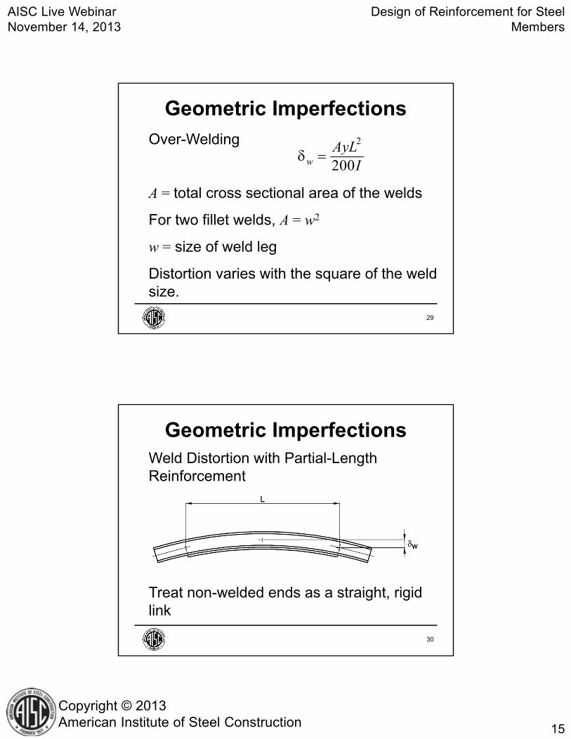
Rs = reduction factor for intermittent welds= L/P
For members welded under load, see Huenersen et al. (1990)
w s wR
Geometric Imperfections
31
Drawing Notes
• Welding shall be performed using techniques and sequences that minimize distortion
• Post-weld tolerances should be addressed
Geometric Imperfections
32

AISC Live WebinarNovember 14, 2013
Design of Reinforcement for Steel Members
17
Copyright © 2013American Institute of Steel Construction
Partial-Length Reinforcement
33
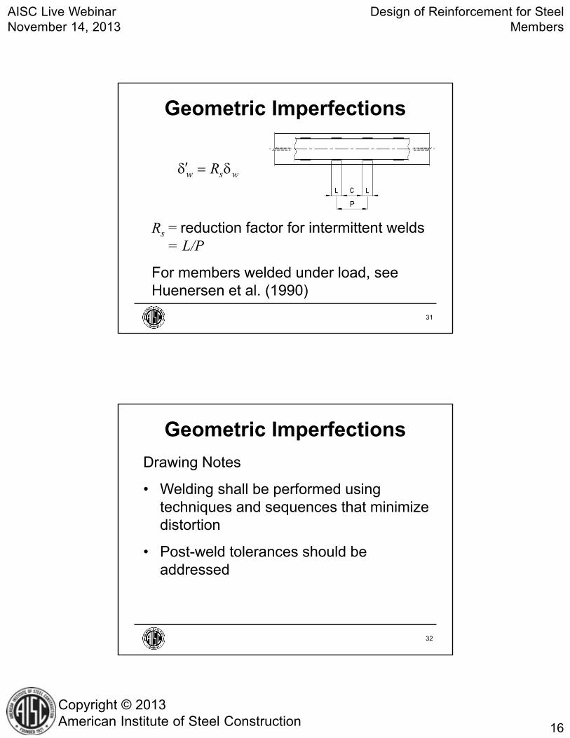
Supplementary reinforcement can be used at locations where primary reinforcement is obstructed.
Supplementary reinforcement is rarely required if a stepped column approach is taken.
Partial-Length Reinforcement
34
AISC Live WebinarNovember 14, 2013
Design of Reinforcement for Steel Members
18
Copyright © 2013American Institute of Steel Construction
Partial-Length Reinforcement
35
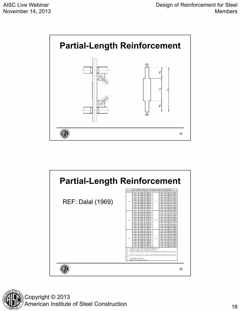
Table 6. Effective length factors for stepped columns from Dalal (1969).Ir / I0 Lr / L Ks2 Ks1 Ir / I0 Lr / L Ks2 Ks1
1.0
0.0 1.000 1.000
2.5
0.0 1.581 1.5810.1 1.000 1.000 0.1 1.486 1.5780.2 1.000 1.000 0.2 1.393 1.5590.3 1.000 1.000 0.3 1.302 1.5160.4 1.000 1.000 0.4 1.216 1.4460.5 1.000 1.000 0.5 1.139 1.3510.6 1.000 1.000 0.6 1.077 1.2400.7 1.000 1.000 0.7 1.034 1.1270.8 1.000 1.000 0.8 1.010 1.0410.9 1.000 1.000 0.9 1.001 1.0051.0 1.000 1.000 1.0 1.000 1.000
3.0
0.0 1.732 1.732
1.5
0.0 1.225 1.2250.1 1.617 1.7280.1 1.184 1.223
0.2 1.144 1.215 0.2 1.502 1.7060.3 1.107 1.196 0.3 1.390 1.6530.4 1.074 1.164 0.4 1.283 1.5690.5 1.046 1.123 0.5 1.185 1.4550.6 1.025 1.079 0.6 1.104 1.317
0.7 1.046 1.1730.7 1.011 1.0390.8 1.003 1.013 0.8 1.014 1.0570.9 1.000 1.002 0.9 1.002 1.0071.0 1.000 1.000 1.0 1.000 1.000
2.0
0.0 1.414 1.414
4.0
0.0 2.000 2.0000.1 1.344 1.412 0.1 1.850 1.9950.2 1.274 1.398 0.2 1.701 1.9660.3 1.207 1.365 0.3 1.553 1.8990.4 1.146 1.312 0.4 1.410 1.7910.5 1.092 1.241 0.5 1.276 1.6440.6 1.050 1.160 0.6 1.159 1.4650.7 1.022 1.082 0.7 1.071 1.2670.8 1.007 1.026 0.8 1.021 1.0920.9 1.000 1.003 0.9 1.002 1.0111.0 1.000 1.000 1.0 1.000 1.000
I = moment of inertia of the non-reinforced member, in.4
Ib = moment of inertia of the reinforced member, in.4
Ks1 = effective length factor for columns with reinforcement held back at one end, Fig.1a.Ks2 = effective length factor for columns with reinforcement held back at both ends, Fig.1b.L = total length of column, in.Lr = length of reinforced section, in.
REF: Dalal (1969)
Partial-Length Reinforcement
36

AISC Live WebinarNovember 14, 2013
Design of Reinforcement for Steel Members
19
Copyright © 2013American Institute of Steel Construction
Ks1 = effective length factor
for columns with reinforcement held back at one end
Ks2 = effective length factor for columns with reinforcement held back at both ends
Partial-Length Reinforcement
37
I0 = moment of inertia of the non-reinforced member, in.4
Ir = moment of inertia of the
reinforced member, in.4
Partial-Length Reinforcement
38

AISC Live WebinarNovember 14, 2013
Design of Reinforcement for Steel Members
20
Copyright © 2013American Institute of Steel Construction
L = total length of column, in.
Lr = length of reinforced section, in.
Partial-Length Reinforcement
39
Table 6. Effective length factors for stepped columns from Dalal (1969).Ir / I0 Lr / L Ks2 Ks1 Ir / I0 Lr / L Ks2 Ks1
1.0
0.0 1.000 1.000
2.5
0.0 1.581 1.5810.1 1.000 1.000 0.1 1.486 1.5780.2 1.000 1.000 0.2 1.393 1.5590.3 1.000 1.000 0.3 1.302 1.5160.4 1.000 1.000 0.4 1.216 1.4460.5 1.000 1.000 0.5 1.139 1.3510.6 1.000 1.000 0.6 1.077 1.2400.7 1.000 1.000 0.7 1.034 1.1270.8 1.000 1.000 0.8 1.010 1.0410.9 1.000 1.000 0.9 1.001 1.0051.0 1.000 1.000 1.0 1.000 1.000
3.0
0.0 1.732 1.732
1.5
0.0 1.225 1.2250.1 1.184 1.223 0.1 1.617 1.7280.2 1.144 1.215 0.2 1.502 1.7060.3 1.107 1.196 0.3 1.390 1.6530.4 1.074 1.164 0.4 1.283 1.5690.5 1.046 1.123 0.5 1.185 1.4550.6 1.025 1.079 0.6 1.104 1.317
0.7 1.046 1.1730.7 1.011 1.0390.8 1.003 1.013 0.8 1.014 1.0570.9 1.000 1.002 0.9 1.002 1.0071.0 1.000 1.000 1.0 1.000 1.000
2.0
0.0 1.414 1.414
4.0
0.0 2.000 2.0000.1 1.344 1.412 0.1 1.850 1.9950.2 1.274 1.398 0.2 1.701 1.9660.3 1.207 1.365 0.3 1.553 1.8990.4 1.146 1.312 0.4 1.410 1.7910.5 1.092 1.241 0.5 1.276 1.6440.6 1.050 1.160 0.6 1.159 1.4650.7 1.022 1.082 0.7 1.071 1.2670.8 1.007 1.026 0.8 1.021 1.0920.9 1.000 1.003 0.9 1.002 1.0111.0 1.000 1.000 1.0 1.000 1.000
I = moment of inertia of the non-reinforced member, in.4
Ib = moment of inertia of the reinforced member, in.4
Ks1 = effective length factor for columns with reinforcement held back at one end, Fig.1a.Ks2 = effective length factor for columns with reinforcement held back at both ends, Fig.1b.L = total length of column, in.Lr = length of reinforced section, in.
Partial-Length Reinforcement
40

AISC Live WebinarNovember 14, 2013
Design of Reinforcement for Steel Members
21
Copyright © 2013American Institute of Steel Construction
Partial-Length ReinforcementIr / I0 Lr / L Ks2 Ks1
2.5
0.0 1.581 1.5810.1 1.486 1.5780.2 1.393 1.5590.3 1.302 1.5160.4 1.216 1.4460.5 1.139 1.3510.6 1.077 1.2400.7 1.034 1.1270.8 1.010 1.0410.9 1.001 1.0051.0 1.000 1.000
41
Pre-Load: required load at the time of reinforcement
Two Cases• Column with Stabilizing Reinforcement:
Pre-load can be neglected
• Column with Non-Stabilizing Reinforcement: Pre-load must be considered
Pre-Load
42

AISC Live WebinarNovember 14, 2013
Design of Reinforcement for Steel Members
22
Copyright © 2013American Institute of Steel Construction
Definition of Stabilizing Reinforcement: For the axis of buckling: rr ≥ 0.85r0
r0 = r for original cross sectionrr = r for reinforced cross section
Pre-Load
43
Stabilizing Reinforcement Concept
Pre-Load
44

AISC Live WebinarNovember 14, 2013
Design of Reinforcement for Steel Members
23
Copyright © 2013American Institute of Steel Construction
Pre-LoadIf rr < 0.85r0, an allowable stress approach can be used.
= 0 + r
0 = stress in non-reinforced member using loads applied before the member is reinforced
r = stress in reinforced member using loads applied after the member is reinforced
45
Pre-Load
00
0
PA
1r
r
PA
For rr < 0.85r0 (non-stabilizing reinforcement)
46

AISC Live WebinarNovember 14, 2013
Design of Reinforcement for Steel Members
24
Copyright © 2013American Institute of Steel Construction
Experimental Results
• Nagaraja and Tall (1963)
• Marzouk and Mohan (1990)
Columns: W615, W818, W831L = 8.00 ft to 10.2 ftReinf. Plates: 0.315 in. to 0.375 in. thickType C Reinforcement
Pre-Load
Type C
47
rr > 0.85r0 for all tests
Notation
P0 = initial pre-load at the time of reinforcement
Pt = maximum total experimental load
Pn = nominal compression strength (AISC Specification Section E3 neglecting pre-load)
Pre-Load
48

AISC Live WebinarNovember 14, 2013
Design of Reinforcement for Steel Members
25
Copyright © 2013American Institute of Steel Construction
Specimen T-9 was not reinforced.
Pre-Load
Spec. KL/rP0
kipsPt
kipsPn
kipsPt / Pn
T-9 48 0 307 298 1.03T-17 48 0 517 475 1.09T-13 48 91 528 475 1.11
1 97 89 228 212 1.082 89 89 239 233 1.034 79 99 288 226 1.275 79 99 270 226 1.196 83 99 236 217 1.09
49
Wu and Grondin (2002)
• 317 FE models
• Pre-loads up to 60% of member strength
• Type C and D Reinforcement
• rr > 0.85r0 for all specimens
• Conclusion: The effect of pre-load is negligible
Pre-Load
Type C
Type D
50

AISC Live WebinarNovember 14, 2013
Design of Reinforcement for Steel Members
26
Copyright © 2013American Institute of Steel Construction
Design reinforcement for an existing W1490 column using LRFD.
Fy = 50 ksi (yield strength)
Lx = Ly = 18 ft (unbraced lengths)
P0 = 300 kips (factored pre-load)
Pu = 1,100 kips (total factored axial load)
Example
51
The available strength of the column without reinforcement is 929 kips.
Try 2 Plates ¾ in. 12 in. welded parallel to each flange. The properties of the reinforced cross section are
Ar = 44.5 in.2
Iry = 578 in.4
rry = 3.60 in.
Example
52

AISC Live WebinarNovember 14, 2013
Design of Reinforcement for Steel Members
27
Copyright © 2013American Institute of Steel Construction
To accommodate existing obstructions, the reinforcement standoff dimension at each end of the column, dr = 4 ft
Example
53
Check for stabilizing reinforcement
The y-axis radius of gyration of the W14×90 is, r0y = 3.70 in.
rr ≥ 0.85r0 ?
3.60 in. > (0.85)(3.70 in.); therefore, the 300 kip pre-load can be neglected
Example
54

AISC Live WebinarNovember 14, 2013
Design of Reinforcement for Steel Members
28
Copyright © 2013American Institute of Steel Construction
Calculate the effective length factor based on a stepped column approach.
The y-axis moment of inertia of the W14×90 is, I0y = 362 in.4
Iry / I0y = 578 in.4 / 362 in.4 = 1.60
(continued)
Example
55
Lr = 18 ft (2)(4 ft) = 10 ft
Lr / L = (10 ft) / (18 ft) = 0.556
Ky = 1.04 (interpolated from tables in Dalal, 1969)
Example
56

AISC Live WebinarNovember 14, 2013
Design of Reinforcement for Steel Members
29
Copyright © 2013American Institute of Steel Construction
1.04 18 ft 12 in./ft62.4
3.60 in.y
KL
r
22
2 2
π 29,000 ksiπ73.5 ksi
62.4e
EF
KLr
AISC Specification Section E3
Example
57
73.5 ksi (0.44)(50 ksi), Use Specification Eqn. E3-2
50 ksi
73.5 ksi
0.658
0.658 50 ksi
37.6 ksi
y
e
F
Fcr yF F
Example
58

AISC Live WebinarNovember 14, 2013
Design of Reinforcement for Steel Members
30
Copyright © 2013American Institute of Steel Construction
237.6 ksi 44.5 in.
1,670 kips
n cr gP F A
Example
0.9 1,670 kips
1,500 kipsnP
1,500 kips > 1,100 kips o.k.
59
Check non-reinforced segment of column for yielding
The area of the W14×90 is, A0 = 26.5 in.2
Pn = (0.9)(50 ksi)(26.5 in.2) = 1,190 kips
1,190 kips > 1,100 kips; therefore, supplementary reinforcement is
not required
Example
60

AISC Live WebinarNovember 14, 2013
Design of Reinforcement for Steel Members
31
Copyright © 2013American Institute of Steel Construction
BEAM DESIGN
61
1. Determine the Reinforcement Type2. Estimate the reinforcement size3. Calculate the properties of the reinforced
cross section using the estimated reinforcement size from Step 2
4. Determine if the compression flange is braced laterally. If so, Steps 5 and 6 are not necessary.
(continued)
General Design Procedure
62

AISC Live WebinarNovember 14, 2013
Design of Reinforcement for Steel Members
32
Copyright © 2013American Institute of Steel Construction
5. Determine the effect of Pre-Load on lateral-torsional buckling
6. Calculate the effect of Partial-Length Reinforcement on lateral-torsional buckling
7. Check strength and stability using the AISC Specification
8. Check serviceability
General Design Procedure
63
Reinforcement Type• Plate at Bottom Flange
– Plate easily clamped in place for fit-up– Welding in the horizontal position – Camber due to weld shrinkage is
upward
64

AISC Live WebinarNovember 14, 2013
Design of Reinforcement for Steel Members
33
Copyright © 2013American Institute of Steel Construction
• Plate at Both Flanges– More strength than a single plate– Top flange may not be accessible
Reinforcement Type
65
• Tee at Bottom Flange– High strength and stiffness– Overhead welding– Consider Stabilizers at Ends of Tee
Reinforcement Type
66

AISC Live WebinarNovember 14, 2013
Design of Reinforcement for Steel Members
34
Copyright © 2013American Institute of Steel Construction
Weak-Axis Bending
Reinforcement Type
67
Torsion
Reinforcement Type
68

AISC Live WebinarNovember 14, 2013
Design of Reinforcement for Steel Members
35
Copyright © 2013American Institute of Steel Construction
Lateral-Torsional Buckling
Reinforcement Type
69
AISC SpecificationFor flexural strength, AISC SpecificationSection F2 applies to doubly-symmetric I-shaped members. Section F4 must be used for singly-symmetric I-shaped members.
70

AISC Live WebinarNovember 14, 2013
Design of Reinforcement for Steel Members
36
Copyright © 2013American Institute of Steel Construction
AISC Specification Section F4
Lp = limiting Lb for yielding
rt = r of compression flange + 1/3 of web (Specification Eqn. F4-11)
1.1p ty
EL rF
AISC Specification
71
AISC Specification Section F4 (continued)
Lr = limiting Lb for inelastic LTB
2 2
1.95 6.76 Lr t
L xc o xc o
FE J JL rF S h S h E
AISC Specification
72

AISC Live WebinarNovember 14, 2013
Design of Reinforcement for Steel Members
37
Copyright © 2013American Institute of Steel Construction
AISC Specification Section F4 (continued)
FL = magnitude of flexural stress in the compression flange at which lateral-torsional buckling is influenced by yielding
When Sxt/Sxc ≥ 0.7
When Sxt/Sxc < 0.7
0.7L yF F
xtL y
xc
SF F
S
AISC Specification
73
AISC Specification Section F4 (continued)
Sxc = section modulus referred to compression flange
Sxt = section modulus referred to tension flange
AISC Specification
74

AISC Live WebinarNovember 14, 2013
Design of Reinforcement for Steel Members
38
Copyright © 2013American Institute of Steel Construction
AISC Specification Section F4 (continued)
ho = distance between the flange centroids
AISC Specification
75
AISC Specification Section F4 (continued)
J = torsion constant (for Iyc/Iy ≤ 0.23, J shall be taken as zero)
Iy = moment of inertia of the cross section about the y-axis
Iyc = moment of inertia of the compression flange about the y-axis
AISC Specification
76
AISC Live WebinarNovember 14, 2013
Design of Reinforcement for Steel Members
39
Copyright © 2013American Institute of Steel Construction
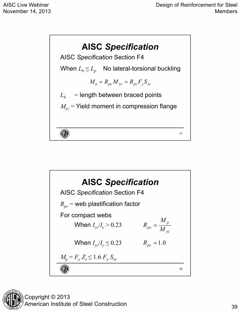
AISC Specification Section F4
When Lb ≤ Lp No lateral-torsional buckling
Lb = length between braced points
Myc = Yield moment in compression flange
AISC Specification
n pc yc pc y xcM R M R F S
77
AISC Specification Section F4
Rpc = web plastification factor
For compact webs
When Iyc/Iy > 0.23
When Iyc/Iy ≤ 0.23
Mp = Fy Zx ≤ 1.6 Fy Sxc
AISC Specification
ppc
yc
MR
M
1.0pcR
78

AISC Live WebinarNovember 14, 2013
Design of Reinforcement for Steel Members
40
Copyright © 2013American Institute of Steel Construction
AISC Specification Section F4 (continued)
When Lp < Lb ≤ Lr
Cb = lateral-torsional buckling modification factor (Specification Eqn. F1-1)
b pn b pc yc pc yc L xc
r p
pc yc
L LM C R M R M F S
L L
R M
AISC Specification
79
AISC Specification Section F4 (continued)
When Lb > Lr
n cr xc pc ycM F S R M
22
21 0.078b b
crxc o tb t
C E LJFS h rL r
AISC Specification
80

AISC Live WebinarNovember 14, 2013
Design of Reinforcement for Steel Members
41
Copyright © 2013American Institute of Steel Construction
AISC Specification Section F4 (continued)
Tension Flange Yielding
When Sxt ≥ Sxc tension flange yielding does not apply.
AISC Specification
81
AISC Specification Section F4 (continued)
When Sxt < Sxc
For compact webs
Myt = FySxt
n pt yt pM R M M
AISC Specification
ppt
yt
MR
M
82

AISC Live WebinarNovember 14, 2013
Design of Reinforcement for Steel Members
42
Copyright © 2013American Institute of Steel Construction
AISC Specification Section F4 applies only to I-shaped members. Can a beam with WT reinforcement be considered I-shaped?
AISC Specification
83
The answer can be found with the classical equation for singly-symmetric beams
Cw = warping constant
2 2 2
2 22 2y x x w b
cryb y
EI C GJLM
IL EI
AISC Specification
84

AISC Live WebinarNovember 14, 2013
Design of Reinforcement for Steel Members
43
Copyright © 2013American Institute of Steel Construction
x, y = centroidal coordinatesy0 = distance from the shear center to the
centroid of the cross section
2 20
1 2xx
A
y x y da yI
AISC Specification
85
Conclusion: AISC Specification Section F4 is slightly conservative if h0 is calculated as defined for the non-reinforced beam.
AISC Specification
The level of conservatism increases as the size of the WT increases relative to the size of the W.
86

AISC Live WebinarNovember 14, 2013
Design of Reinforcement for Steel Members
44
Copyright © 2013American Institute of Steel Construction
AISC Specification
Where the WT is large, relative to the W, an alternative definition of h0 may be appropriate.
87
Partial-Length Reinforcement
88

AISC Live WebinarNovember 14, 2013
Design of Reinforcement for Steel Members
45
Copyright © 2013American Institute of Steel Construction
b LTB bC C REF: Trahair and Kitipornchai (1971)
Partial-Length Reinforcement
89
021 1er
LTBer
MdL M
Partial-Length Reinforcement
90

AISC Live WebinarNovember 14, 2013
Design of Reinforcement for Steel Members
46
Copyright © 2013American Institute of Steel Construction
Mer = elastic lateral-torsional buckling moment of reinforced member assuming full-length reinforcement
Me0 = elastic lateral-torsional buckling moment of non-reinforced member
Use the actual value of J (not J = 0)
for all values of Iyc/Iy when calculating LTB
Partial-Length Reinforcement
91
Finite Element Results
• Lui and Gannon (2009b)• Beams: W12197.87 ft long• Reinf. Plates: 0.394 in. 5.32 in.• Type A and C Reinforcement
Partial-Length Reinforcement
Type A Type C
92

AISC Live WebinarNovember 14, 2013
Design of Reinforcement for Steel Members
47
Copyright © 2013American Institute of Steel Construction
Partial-Length Reinforcement
SpecNo.
ReinfType
dr
(in.)Lr / L
βFE
(%)βLTB
(%)βFE / βLTB
A1 A 1.89 0.96 100 98.6 1.01A2 A 15.6 0.67 89.4 88.8 1.01A3 A 31.6 0.33 74.3 77.4 0.960C1 C 1.89 0.96 100 97.0 1.03C2 C 15.6 0.67 90.3 75.2 1.20C3 C 31.6 0.33 75.4 49.7 1.52
βFE = reduction in FE models
βLTB = nominal reduction factor
93
The magnitude of pre-load has no effect on flexural yielding strength.
Pre-Load
94
AISC Live WebinarNovember 14, 2013
Design of Reinforcement for Steel Members
48
Copyright © 2013American Institute of Steel Construction
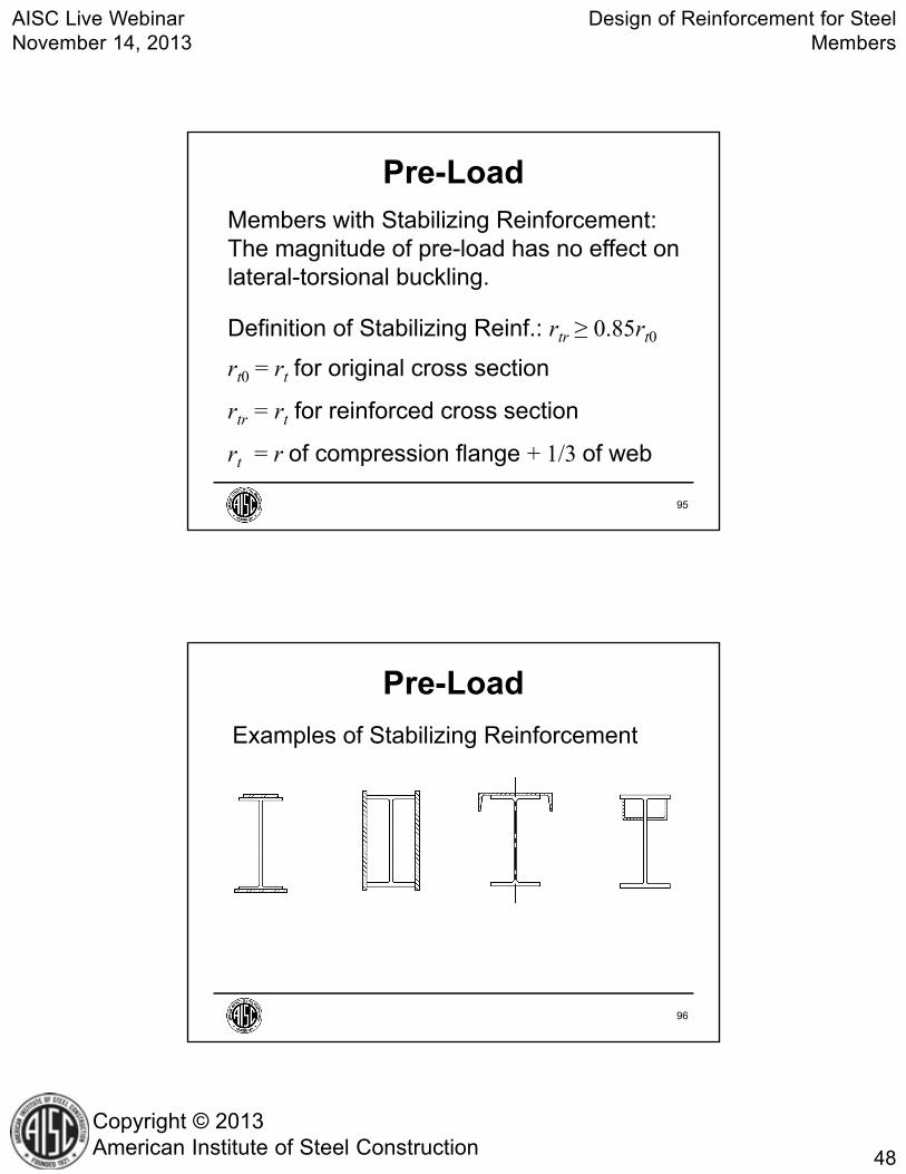
Members with Stabilizing Reinforcement: The magnitude of pre-load has no effect on lateral-torsional buckling.
Definition of Stabilizing Reinf.: rtr ≥ 0.85rt0
rt0 = rt for original cross section
rtr = rt for reinforced cross section
rt = r of compression flange + 1/3 of web
Pre-Load
95
Examples of Stabilizing Reinforcement
Pre-Load
96

AISC Live WebinarNovember 14, 2013
Design of Reinforcement for Steel Members
49
Copyright © 2013American Institute of Steel Construction
Examples of Non-Stabilizing Reinforcement
Pre-Load
97
Pre-Load
b pn b pc yc pc yc L xc
r p
pc yc
L LM C R M R M F S
L L
R M
Lateral-Torsional Buckling with non-stabilizing reinforcement, replace FL with F′L in AISC Specification Equation F4-2.
98

AISC Live WebinarNovember 14, 2013
Design of Reinforcement for Steel Members
50
Copyright © 2013American Institute of Steel Construction
Cbi = Cb for the pre-load moment diagramMxi = pre-load momentfbxi = flexural stress due to pre-loadSx = S for the non-reinf. member
Pre-Load
bxiL L
bi
fF F
C xi
bxix
Mf
S
99
Experimental Results
• Lui and Gannon (2009a)• Beams: W1219• Reinf. Plates: 0.374 in. 5.39 in.• Type A Reinforcement
Pre-Load
Type A
100

AISC Live WebinarNovember 14, 2013
Design of Reinforcement for Steel Members
51
Copyright © 2013American Institute of Steel Construction
Notation
M0= initial pre-load moment at the time of reinforcement
Me = maximum experimental moment
Mn= nominal moment calculated using AISC Specification Section F4 with F′L replacing FL in Equation F4-2.
Pre-Load
101
Specimens P1 and P2 were not reinforced.
Pre-Load
Spec.Lb
ftM0
kip-ftMe
kip-ftMn
kip-ftMe / Mn
P1 7.87 0 55.8 57.1 0.977P2 3.94 0 99.5 83.2 1.20A1 7.87 0 99.2 78.6 1.26A2 7.87 14.7 99.2 69.9 1.42A3 7.87 29.5 92.6 61.2 1.51C1 3.94 0 127 107 1.19C2 3.94 25.1 118 103 1.15C3 3.94 50.2 111 98.2 1.13
102

AISC Live WebinarNovember 14, 2013
Design of Reinforcement for Steel Members
52
Copyright © 2013American Institute of Steel Construction
Shear Flow
Ap = area of the reinforcing plateIrx = strong-axis moment of inertia of the
built-up memberVr = required shear forcev = shear force per unit length
r
rx
V Qv
I pQ A y
Welding Issues
103
For reinforcing plates with two welds, the shear force per unit length of weld is v/2
For shear flow at columns, see Goel and Aslani (1992)
Welding Issues
104

AISC Live WebinarNovember 14, 2013
Design of Reinforcement for Steel Members
53
Copyright © 2013American Institute of Steel Construction
Welding IssuesAnchor Force
rcA
rx
M QF
I
rcM rcM
105
Welding Issues
Mrc = required moment at the theoretical cutoff point
drt = development length
106

AISC Live WebinarNovember 14, 2013
Design of Reinforcement for Steel Members
54
Copyright © 2013American Institute of Steel Construction
Welding IssuesMembers Welded Under Load
•Consider the effects of welding heat on member strength during the welding operation.
•Elevated temperatures near the weld cause a reduction in material properties of the base material.
•See Huenersen et al. (1990)
107
Questions?
Bo Dowswell, P.E., Ph.D.
Principal
ARC International, LLC

AISC Live WebinarNovember 14, 2013
Design of Reinforcement for Steel Members
55
Copyright © 2013American Institute of Steel Construction
ReferencesBlodgett, O.W. (1966), Design of Welded Structures, The James F. Lincoln Arc Welding Foundation, Cleveland, OH.
Dalal, S.T. (1969), “Some Non-Conventional Cases of Column Design,” Engineering Journal, American Institute of Steel Construction, January.
Goel, S.C. and Aslani, F. (1992), “Analytical Criteria for Stitch Strength of Built-up Compression Members,” Engineering Journal, American Institute of Steel Construction, Third Quarter.
Huenersen, G., Haensch, H. and Augustyn, J. (1990), “Repair Welding Under Load,” Welding in the World, Vol. 28, No. 9/10, pp. 174-182.
109
ReferencesLui, Y. and Gannon, L. (2009a), “Experimental Behavior and Strength of Steel Beams Strengthened while Under Load,” Journal of Constructional Steel Research, Vol. 65, pp. 1346-1354.
Lui, Y. and Gannon, L. (2009b), “Finite Element Study of Steel Beams Reinforced while Under Load,” Engineering Structures, Vol. 31, pp. 2630-2642.
Marzouk, H. and Mohan, S. (1990), “Strengthening of Wide Flange Columns Under Load,” Canadian Journal of Civil Engineering, Vol. 17, pp. 835-843.
Nagaraja, N.R. and Tall, L. (1963), “Columns Reinforced Under Load,” Welding Research Supplement, April, pp. 177s-185s.
110

AISC Live WebinarNovember 14, 2013
Design of Reinforcement for Steel Members
56
Copyright © 2013American Institute of Steel Construction
ReferencesTrahair, N.S. and Kitipornchai, S. (1971), “Elastic Lateral Buckling of Stepped I-Beams,” Journal of the Structural Division, ASCE, Vol. 97, No. ST10.
Wu, Z. and Grondin, G.Y. (2002), Behavior of Steel Columns Reinforced with Welded Steel Plates, Structural Engineering Report Number 250, University of Alberta Department of Civil and Environmental Engineering, December.
111
Within 1 business day…
• You will receive an email on how to report attendancefrom: [email protected]
• Be on the lookout: Check your spam filter! Checkyour junk folder!
• Completely fill out online form. Don’t forget to checkthe boxes next to each attendee’s name!
OR…
CEU Certificates

AISC Live WebinarNovember 14, 2013
Design of Reinforcement for Steel Members
57
Copyright © 2013American Institute of Steel Construction
Access available in 24 hours…
• Go to:
http://www.wynjade.com/aiscspring13/webinarCEUUsername: Your Web ID (found on your reg. receipt)Password: Your Last Name
• Completely fill out online form. Don’t forget to checkthe boxes next to each attendee’s name!
• Questions? Please email us at [email protected].
CEU Certificates
Night School Course 4 – Fundamentals of Earthquake Engineering for Building Structures
Written and presented by Rafael Sabelli, S.E.
Class begins February 2014!
www.aisc.org/nightschool
AISC Night School

AISC Live WebinarNovember 14, 2013
Design of Reinforcement for Steel Members
58
Copyright © 2013American Institute of Steel Construction
100+ hours of recorded presentations
– 1 to 6 hour sessions available. – Free to view.– CEUs/PDHs available with purchase of a quiz.
www.aisc.org/webinars
AISC eLearning
Thank YouPlease give us your feedback!
Survey at conclusion of webinar.