Embed Size (px)
Citation preview

AirMax5N/ESD
802.11a/n 1T1R Wireless
Outdoor CPE
User’s Manual Version 3.0

Copyright and Disclaimer
AirLive AirMax5N User’s Manual
Version 3.0 This guide is written for firmware version 3.0 or later.
Copyright & Disclaimer No part of this publication may be reproduced in any form or by any means, whether electronic, mechanical, photocopying, or recording without the written consent of OvisLink Corp. OvisLink Corp. has made the best effort to ensure the accuracy of the information in this user’s guide. However, we are not liable for the inaccuracies or errors in this guide. Please use with caution. All information is subject to change without notice
This product requires professional installation. Please do not attempt to install the device without the necessary knowledge in regards to your country's wireless regulations.
Functions and features in your product’s firmware might be different due to regulations in your country.

Copyright and Disclaimer
AirLive AIRMAX5N/ESD User’s Manual ii
Federal Communication Commission Interference Statement This equipment has been tested and found to comply with the limits for a Class B digital device, pursuant to Part 15 of the FCC Rules. These limits are designed to provide reasonable protection against harmful interference in a residential installation.
This equipment generates, uses and can radiate radio frequency energy and, if not installed and used in accordance with the instructions, may cause harmful interference to radio communications. However, there is no guarantee that interference will not occur in a particular installation. If this equipment does cause harmful interference to radio or television reception, which can be determined by turning the equipment off and on, the user is encouraged to try to correct the interference by one of the following measures: . Reorient or relocate the receiving antenna. . Increase the separation between the equipment and receiver. . Connect the equipment into an outlet on a circuit different from that to which the receiver is connected. . Consult the dealer or an experienced radio/TV technician for help. FCC Caution: To assure continued compliance, any changes or modifications not expressly approved by the party responsible for compliance could void the user's authority to operate this equipment. (Example - use only shielded interface cables when connecting to computer or peripheral devices). FCC Radiation Exposure Statement
This equipment complies with FCC RF radiation exposure limits set forth for an uncontrolled environment. This equipment should be installed and operated with a minimum distance of 20 centimeters between the radiator and your body. This transmitter must not be co-located or operating in conjunction with any other antenna or transmitter. The antennas used for this transmitter must be installed to provide a separation distance of at least 20 cm from all persons and must not be co-located or operating in conjunction with any other antenna or transmitter. THIS DEVICE COMPLIES WITH PART 15 OF THE FCC RULES. OPERATION IS SUBJECT TO THE FOLLOWING TWO CONDITIONS:
(1) THIS DEVICE MAY NOT CAUSE HARMFUL INTERFERENCE AND
(2) THIS DEVICE MUST ACCEPT ANY INTERFERENCE RECEIVED, INCLUDING INTERFERENCE THAT MAY CAUSE UNDESIRED OPERATION. All Trademarks are properties of their respective holders.

Table of Contents
i
AirLive AirMax5N/ESD User’s Manual
Table of Contents
1. Introduction.............................................................................................. 1
1.1 Overview............................................................................................ 1
1.2 Special Notice.................................................................................... 1
1.3 How to Use This Guide ...................................................................... 2
1.4 Firmware Upgrade and Tech Support ................................................ 3
1.5 Features ............................................................................................ 4
1.6 Wireless Operation Modes................................................................. 4
1.6.1 Access Point Mode ......................................................................................5 1.6.2 Repeater Mode............................................................................................5 1.6.3 WDS Bridge Mode.......................................................................................6 1.6.4 WDS Repeater Mode (WDS + AP) ..............................................................6 1.6.5 Client Infrastructure Mode ...........................................................................7 1.6.6 WISP Router Mode......................................................................................7 1.6.7 AP Router Mode ..........................................................................................8
2. Installing the AirMax5N ........................................................................... 9
2.1 Before You Start................................................................................. 9
2.2 Package Content ............................................................................. 10
2.3 Knowing your AirMax5N................................................................... 10
2.4 Hardware Installation ....................................................................... 12
2.4.1 Standard Pole Mount .................................................................................13 2.4.2 Installing External Antenna ........................................................................13
2.5 Restore Settings to Default .............................................................. 15
3. Configuring the AirMax5N..................................................................... 16
3.1 Important Information....................................................................... 16
3.2 Prepare your PC.............................................................................. 16
3.3 Management Interface..................................................................... 17
3.4 Introduction to Web Management .................................................... 18
3.4.1 Welcome Screen and Login.......................................................................18
3.5 Initial Configurations ........................................................................ 20
3.5.1 Choose the wireless Operation Modes......................................................20 3.5.2 Change the Device’s IP Address ...............................................................21 3.5.3 Set the Time and Date...............................................................................22 3.5.4 Change Password .....................................................................................22

Table of Contents
AirLive AirMax5N/ESD User’s Manual ii
4. Web Management: Wireless and WAN Settings.................................. 23
4.1 About AirMax5N’s Menu Structure ................................................... 23
4.2 Operation Modes (Wireless and WAN Settings)............................... 24
4.2.1 Network SSID ............................................................................................25 4.2.2 Site Survey ................................................................................................26 4.2.3 Radio Mode (11a, 11a/n mixed, 11n) .........................................................27 4.2.4 Channel .....................................................................................................27 4.2.5 Channel Width ...........................................................................................27 4.2.6 Data Rate ..................................................................................................28 4.2.7 Security Settings........................................................................................28 4.2.8 Antenna Settings .......................................................................................33 4.2.9 Transmit Power..........................................................................................33 4.2.10 Advance Settings (Wireless)....................................................................33 4.2.11 Access Control (ACL)...............................................................................34 4.2.12 Multiple SSID...........................................................................................35 4.2.13 WMM QoS...............................................................................................37 4.2.14 Bandwidth Control ...................................................................................40
4.3 WDS Settings .................................................................................. 41
4.4 Router Mode Settings ...................................................................... 42
4.4.1 WISP Router Mode....................................................................................42 4.4.2 AP Router Mode ........................................................................................43 4.4.3 WAN Port Settings.....................................................................................43 4.4.4 Dynamic DNS Settings ..............................................................................44 4.4.5 Remote Management Settings ..................................................................44 4.4.6 DHCP Server .............................................................................................45 4.4.7 DMZ...........................................................................................................46 4.4.8 IP Routing Settings ....................................................................................46 4.4.9 Virtual Server Settings ...............................................................................48 4.4.10 IP Filtering Settings..................................................................................49
5. Web Management 2: System Configuration and Status ..................... 50
5.1 System Configuration ...................................................................... 50
5.1.1 Device IP Settings .....................................................................................50 5.1.2 Time Settings.............................................................................................52 5.1.3 Password Settings.....................................................................................52 5.1.4 System Management.................................................................................53 5.1.5 Ping Watchdog ..........................................................................................53 5.1.6 Firmware Upgrade.....................................................................................54 5.1.7 Configuration Save and Restore................................................................55 5.1.8 Factory Default ..........................................................................................56
5.2 Device Status................................................................................... 57
5.2.1 Device Information......................................................................................57 5.2.2 Wireless Information...................................................................................58 5.2.3 Internet Information.....................................................................................58

Table of Contents
iii
AirLive AirMax5N/ESD User’s Manual
5.2.4 Wireless Client Table .................................................................................59 5.2.5 System Log.................................................................................................59
6. Antenna Alignment................................................................................ 60
6.1 About AirMax5N’s Antenna .............................................................. 60
6.1.1 Mounting Adjustment .................................................................................60
6.2 Preparation before Installation ......................................................... 60
6.3 Antenna Alignment using Signal Survey........................................... 61
7. Application Example: Infrastructure .................................................... 63
7.1 Application Environment .................................................................. 63
7.2 Central AP: Access Point Mode ....................................................... 64
7.2.1 AP Wireless Settings .................................................................................64
7.3 Client: Client Mode .......................................................................... 67
7.3.1 Device C IP Address..................................................................................67 7.3.2 Client Wireless Settings.............................................................................68
8. Specifications ........................................................................................ 70
8.1 Features .......................................................................................... 70
8.1.1 General Feature ........................................................................................70
8.2 Specifications................................................................................... 70
9. Wireless Network Glossary................................................................... 73

1. Introduction
AirLive AirMax5N/ESD User’s Manual 1
1 1. Introduction
1.1 Overview
The AIRMAX5N is a 1T1R wireless outdoor multi-function device based on IEEE 802.11a/n 5-GHz radio technologies. When installed in upright position, it is rain and splash proof. It features an integrated 16dBi patch antenna and passive POE to simplify the installation. The built-in antenna can provide up to 3km* of distance depending on conditions. If more distance is required, an R-SMA antenna connector is available for external antenna. The firmware of the AP provides up to 7 operations modes* to satisfy different application environments.
1.2 Special Notice
This product requires professional installation. Please do not attempt to install the device without the necessary knowledge in regards to your country's wireless regulations.
Functions and features in your product’s firmware might be different due to regulations in your country.

1. Introduction
AirLive AirMax5N/ESD User’s Manual
2
1.3 How to Use This Guide
AirMax5N is an advanced wireless CPE with many functions. It is recommended that you read through the entire user’s guide whenever possible. The user guide is divided into different chapters. You should read at least go through the first 3 chapters before attempting to install the device. Recommended Reading
� Chapter 1
� 1.5 Operation Modes: This section explains the usage of each wireless operation mode. It is a must read.
� Chapter 2: This chapter is about hardware installation. You should read through the entire chapter.
� Chapter 3:
� 3.1 Important Information: This section has default settings information such as IP, password, SSID, and recommended browser
� 3.3 Management Interface: This section introduces Web, Telnet, and configurations.
� 3.4 Introduction to Web Management: This section tells you how to get into the Web UI using HTTP. In addition, it also explains about the basic menu structure.
� 3.5 Initial Configurations: This section guide you through the essential initial configurations such as choosing operation mode, set device IP, password, and change frequency domain.
� Chapter 4 Web Management – Wireless and WAN Settings: This chapter explain the wireless functions and router mode settings in the AirMax5N. If time permitted, you should read through the entire chapter.
� 4.2 Operation Mode (wireless): Operation mode is the page where all the wireless settings and router mode settings are. Therefore, it is advised that you must read through the entire section.
� 4.2.3 Site Survey: Site Survey is the connection wizard that will search for available networks and let you connect with the select network by simply clicking. It also includes RSSI signal survey for antenna alignment.
� 4.2.5 and 4.2.6 Channel and Channel Width: This part explains the concept of variable Channel Width and how to use them. Channel Width can be 40MHz, or 20MHz.
� 4.3 WDS Settings: Here explains the WDS setting page.

1. Introduction
AirLive AirMax5N/ESD User’s Manual 3
� Chapter 5: Web Management 2: Configurations and Status
This chapter explains all the non-wireless settings and status such as IP settings, Ping Watchdog.
� 5.1.5 PING Watchdog: PING watchdog is a crucial function to keep your wireless connection alive. When AirMax5N can’t get a response from remote devices, it will attempt to re-establish the connection.
� 5.1.7 Configuration Save and Restore: You should always backup your configurations so you can restore in the event of system crash.
� Chapter 7: Application Example: Infrastructure
In this chapter, you will learn how to use AP mode, Client Infrastructure Mode, and Bridge Infrastructure mode in one application example. In addition, you will also learn how to make multiple SSID and bandwidth control.
.
� Chapter 9: Wireless Network Glossary
Explanations on wireless network technical terms from A to Z. Highly recommended for referencing when you encounter an unfamiliar term.
1.4 Firmware Upgrade and Tech Support
If you encounter a technical issue that cannot be resolved by information on this guide, we recommend that you visit our comprehensive website support at www.airlive.com. The tech support FAQ are frequently updated with latest information. In addition, you might find new firmware that either increase software functions or provide bug fixes for AirMax5N. You can reach our on-line support center at the following link: http://www.airlive.com/support/support_2.jsp Since 2009, AirLive has added the “Newsletter Instant Support System” on our website. AirLive Newsletter subscribers receives instant email notifications when there are new download or tech support FAQ updates for their subscribed airlive models. To become an AirLive newsletter member, please visit: http://www.airlive.com/member/member_3.jsp

1. Introduction
AirLive AirMax5N/ESD User’s Manual
4
Figure 1.4: AirLive Newsletter Suppport System
1.5 Features
� 1T1R 150Mbps
� IEEE 802.11a/n
� Runs from 5.1GHz to 5.8GHz Spectrum
� 2 x 10/100 Ethernet Port with one Passive PoE port
� Built-in 16dBi Antenna
� AP, Repeater, Bridge, Client, Router, WISP Modes
� R-SMA Female Connector for External Antenna
� Passive PoE Powered
� Reset button on the POE Injector
� Support Wireless Access Control, Client Isolation
1.6 Wireless Operation Modes
The AirMax5N can perform as a multi-function wireless device. Through the AirLogic web interface, users can easily select which wireless mode they wish the AirMax5N to perform.
The AirMax5N can be configured to operate in the following wireless operation modes:

1. Introduction
AirLive AirMax5N/ESD User’s Manual 5
1.6.1 Access Point Mode
When operating in the Access Point mode, the AIRMAX5N becomes the center hub of the wireless network. All wireless cards and clients connect and communicate through AirMax5N. This type of network is known as “Infrastructure network”. Other AirMax5N or 802.11a/n CPE can connect to AP mode through “Client Infrastructure Mode”.
1.6.2 Repeater Mode
In Repeater mode, the AIRMAX5N functions as a repeater that extends the range of remote wireless LAN. The AirMax5N’s repeater mode is a universal repeater, not WDS repeater. Because the radio is divided into client + AP mode, the Repeater mode will have less performance and distance. We recommended using a dual radio product like Airlive Duo or A.Duo if you require full performance in this application.

1. Introduction
AirLive AirMax5N/ESD User’s Manual
6
1.6.3 WDS Bridge Mode
This mode is also known as “WDS Pure MAC mode”. When configured to operate in the Wireless Distribution System (WDS) Mode, the AIRMAX5N provides bridging functions with remote LAN networks in the WDS system. The system will support up to total of 8 bridges in a WDS network (by daisy chain). However, each bridge can only associate with maximum of 4 other bridges in the WDS configuration. This mode is best used when you want to connect LAN networks together wirelessly (for example, between office and warehouse). If you have more than 2 AP in WDS Bridges mode, please remember to avoid duple connection to one device, otherwise the network loop can be occurred. This mode usually delivers faster performance than infrastructure mode.
1.6.4 WDS Repeater Mode (WDS + AP)
In WDS Repeater mode, the AIRMAX5N functions as a repeater that extends the range of remote wireless LAN. In this mode, the remote Access Point must have WDS (Wireless Distribution System) capability. If you require the PC’s MAC addresses to be preserved when the data pass through the Repeater, it is necessary to use the WDS Repeater mode. Because the radio is divided into WDS + AP mode, the Repeater mode will have less performance and distance.

1. Introduction
AirLive AirMax5N/ESD User’s Manual 7
1.6.5 Client Infrastructure Mode
This mode is also known as “Client” mode. In Client Infrastructure mode, the AIRMAX5N acts as if it is a wireless adapter to connect with a remote Access Point. Users can attach a computer or a router to the LAN port of AirMax5N to get network access. This mode is often used by WISP on the subscriber’s side.
1.6.6 WISP Router Mode
In WISP Router Mode, AIRMAX5N connects to the remote Access Point as in Client Infrastructure Mode. On the LAN side, it acts like a wired router for IP sharing function. This mode is best used for IP sharing application for WISP subscribers. In this mode, the WAN is the wireless client side; the LAN is the wired side.

1. Introduction
AirLive AirMax5N/ESD User’s Manual
8
1.6.7 AP Router Mode
In AP Router Mode, the AirMax5N behaves like a wireless router. The non-PoE port of the AirMax5N will become WAN port. Both the wireless and the passive PoE port of AirMax5N becomes the LAN side. User can manage the AirMax5N through the wireless or passive PoE port. And if the remote management is opened, user can also get to manage AirMAx5N via the WAN side.

2. Installing the AirMax5N
AirLive AirMax5N/ESD User’s Manual 9
2 2. Installing the AirMax5N
This section describes the hardware features and the hardware installation procedure for the AIRMAX5N. For software configuration, please go to chapter 3 for more details.
2.1 Before You Start
It is important to read through this section before you install the AirMax5N
� The AirMax5N comes with everything you need to start installation with exception of the PoE Ethernet Cable. You can use a good quality CAT-5E outdoor graded Ethernet cable (shielded with anti-UV) according to the length you need.
� The AirMax5N must be installed in the upright position if the unit is located in outdoor or wet environments.
� The use of 5GHz spectrum, the allowed channels can be very in different country. Please consult with your country’s telecom regulation first.
� The integrated antenna has forward coverage angle of 20 degree in vertical and 30 degree in horizontal direction.
� The AirMax5N is a 5GHz CPE device only; it cannot operate in 2.4GHz.
� If you choose to use the external antenna, please remember to connect the external antenna first before power on AirMax5N.

2. Installing the AirMax5N
AirLive AirMax5N/ESD User’s Manual 10
2.2 Package Content
The AIRMAX5N package contains the following items:
� One AIRMAX5N main unit
� One 12V 1A DC power adapter
� Passive PoE DC Injector
� 1 x Plastic Straps
� User’s Guide CD
� Quick Start Guide
The PoE Ethernet cable is not included in the package. You may choose an outdoor specification Ethernet cable according to the length you need.
2.3 Knowing your AirMax5N
Below are descriptions and diagrams of the product:

2. Installing the AirMax5N
AirLive AirMax5N/ESD User’s Manual 11
LED Behavior
LED Indicator State Description
ON The WLAN Broadband Router is powered ON. 1. PWR LED
Off The WLAN Broadband Router is powered Off.
ON Wireless Radio ON.
Off Wireless Radio Off. 2. WLAN LED
Flashing Data is transmitting or receiving on the wireless.
ON Port linked.
Off No link. 3. WAN LED
Flashing Data is transmitting or receiving on the WAN interface.
ON Port linked.
Off No link. 4. LAN LED
Flashing Data is transmitting or receiving on the LAN interface.

2. Installing the AirMax5N
AirLive AirMax5N/ESD User’s Manual 12
2.4 Hardware Installation
Please prepare a screw driver and an outdoor graded PoE Ethernet cable with adequate length according to your need.
1. Push the button in the side to remove upper housing.
2. Pass through Ethernet cable from the hole; insert the cable to Secondary port.
3. Install the upper housing and make sure the housing is well installed.
4. Install POE Injector
2. Installing the AirMax5N
AirLive AirMax5N/ESD User’s Manual 13
2.4.1 Standard Pole Mount
Your AirMax5N comes standard with 1 plastic straps for pole mounting. Please follow the procedure below to install:
1. Put the plastic strap through the holes on the Pole Mount holders.
2. Thread the thinner end of the strap into the opening on the other end. Then tighten the strap around the pole as tightly as possible.
2.4.2 Installing External Antenna
The AirMax5N is equipped with a 16dBi built-in patch antenna. It has horizontal coverage angle of 30 and vertical coverage angle of 20 degree in the forward direction. If the built-in antenna cannot meet your requirement, you can connect AirMax5N with an external antenna via the Female R-SMA connector. Before you start, you would need an antenna converter cable. For example; if you want to connect directly to an outdoor antenna with female N-Type connector, you would need a Male R-SMA to Male N-Type connector. Please note that you should not connect the power until the external antenna is attached to avoid damaging the RF. Once you have the converter cable, please follow the installation steps below.

2. Installing the AirMax5N
AirLive AirMax5N/ESD User’s Manual 14
1. Remove the cover. 2. Connect the converter cable to the antenna port. Please run the cable through the cable hole
3. Push back the cover. 4. You should connect the AirMax5N to an external antenna before power on to avoid damaging the RF

2. Installing the AirMax5N
AirLive AirMax5N/ESD User’s Manual 15
5. Please go to the web configuration. Select “Wireless Settings” ->operation mode-> Advance Settings. Change the “Antenna Setting” to “External”.
2.5 Restore Settings to Default
If you have forgotten your AirMax5N’s IP address or password, you can restore your AirMax5N to the default settings by pressing on the “reset button” for more than 5 seconds. The reset button is located on the PoE Kit. Please see diagram below for details.

3. Configuring the AirMax5N
AirLive AirMax5N/ESD User’s Manual 16
In this chapter, we will explain AirMax5N’s available management interfaces and how to get into them. Then, we will provide the introduction on Web Management and recommended initial settings. For detail explanations on Web Management functions, please go to Chapter 4 and 5.
3.1 Important Information
The following information will help you to get start quickly. However, we recommend you to read through the entire manual before you start. Please note the password and SSID are case sensitive.
� The default IP address is: 192.168.1.1 Subnet Mask: 255.255.255.0
� The default user’s name is: admin
� The default password is: airlive
� The default wireless mode is : Client mode
� After power on, please wait for 2 minutes for AirMax5N to finish boot up
� Please remember to click on “Apply” for new settings to take effect
3.2 Prepare your PC
The AIRMAX5N can be managed remotely by a PC through either the wired or wireless network. The default IP address of the AIRMAX5N is 192.168.1.1 with a subnet mask of 255.255.255.0. This means the IP address of the PC should be in the range of 192.168.1.2 to 192.168.1.254.
To prepare your PC for management with the AirMax5N, please do the following:
1. Connect your PC directly to the LAN port on the DC Injector of AirMax5N 2. Set your PC’s IP address manually to 192.168.1.100 (or other address in the same
subnet)
3 3. Configuring the
AirMax5N

3. Configuring the AirMax5N
AirLive AirMax5N/ESD User’s Manual 17
You are ready now to configure the AirMax5N using your PC.
3.3 Management Interface
The AirMax5N can be configured using the web interfaces:
Web Management (HTTP): You can manage your AirMax5N by simply typing its IP address in the web browser. Most functions of AirMax5N can be accessed by web management interface. We recommend using this interface for initial configurations. To begin, simply enter AirMax5N’s IP address (default is 192.168.1.1) on the web browser. The default username is “admin” and password is “airlive”.

3. Configuring the AirMax5N
AirLive AirMax5N/ESD User’s Manual 18
3.4 Introduction to Web Management
3.4.1 Welcome Screen and Login
After the procedure above, the Welcome Screen will appear. Welcome Screen gives a brief introduction of the AirMax5N’s main function category. By click on the function category, it will direct you to the corresponding web management menu.
� Wireless Settings: Click on this part will bring you to the wireless operation mode menu. The AirMax5N’s wireless settings are different between wireless modes. Only functions that are applicable to the wireless mode will show to simplify configuration. For example, multiple SSID option is workable for Access Point, AP Router, WDS + AP mode. Therefore, the function will only appear in these 3 modes. For this reason, the first step to configure the AirMax5N is to select the wireless mode. The router mode specific functions are also in this menu category. For explanation of different wireless modes, please refer to Chapter 1.
� System Configuration: All non-wireless and router mode settings are in this category. The system configurations including changing password, upload firmware, backup configuration, settings PING watchdog, and setting management interface.
� Device Status: This section for monitoring the status of AirMax5N. It provides information on device status, Ethernet status, wireless status, wireless client table, and system log.
TIPS: You can choose any menu categories to begin; you can switch to other menu later
When you access to the AirMax5N, it will require you to enter the username and password. Please enter “admin” for the User Name, and “airlive” (all lower cases) for password.
3. Configuring the AirMax5N
AirLive AirMax5N/ESD User’s Manual 19
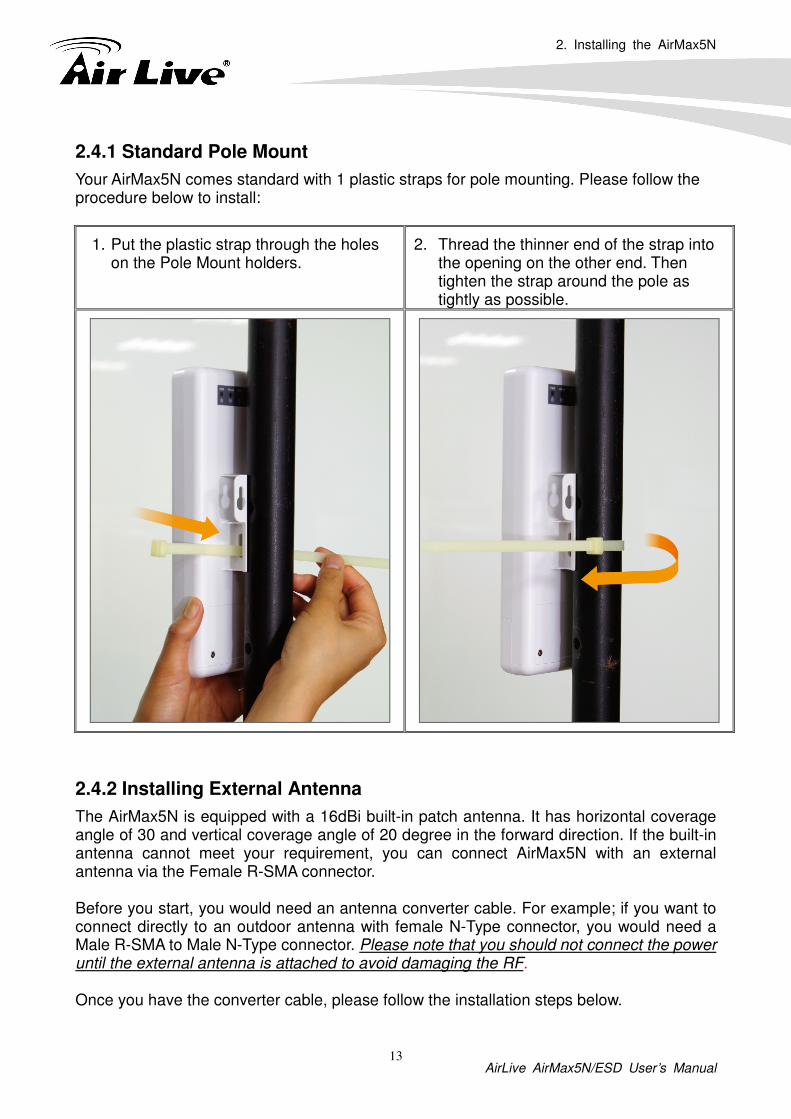
After you enter the correct password, the welcome screen will appear. Than chose the corresponding menu you needed, and the web interface will be arranged as below:
Wireless Settings
System Configuration

3. Configuring the AirMax5N
AirLive AirMax5N/ESD User’s Manual 20
3.5 Initial Configurations
We recommend users to browse through AirMax5N’s web management interface to get an overall picture of the functions and interface. Below are the recommended initial configurations for first time login:
3.5.1 Choose the wireless Operation Modes
The wireless settings of AirMax5N are dependent on the wireless operation mode you choose. Therefore, the first step is to choose the operation mode. For explanation on when to use what operation mode, please refer to Chapter 1
When you click on the “Wireless Settings” on the welcome screen or the “Operation Mode” on the top menu bar, the following screen will appear.
Follow the example below to change to “Client” mode
1. Select “Client” mode.
2. Click on “change mode” button
3. The AP will reboot, wait for about one minute
Current Wireless Mode
Click to configure wireless settings

3. Configuring the AirMax5N
AirLive AirMax5N/ESD User’s Manual 21
3.5.2 Change the Device’s IP Address
The default IP address is at 192.168.1.1. You should change it to the same subnet as your network. Also, if you want to manage AirMax5N remotely, you have to set the Gateway and DNS server information.
To setup the IP settings for AirMax5N, please select “System Configuration” -> Device IP Settings”. After entering the IP information, click on “Apply” to finish.
2
1
1
2
3

3. Configuring the AirMax5N
AirLive AirMax5N/ESD User’s Manual 22
3.5.3 Set the Time and Date
It is important that you set the date and time for your AirMax5N so that the system log will record the correct date and time information. Please go to “System Configuration” ->Time Settings. We recommend you choose “Enable NTP” so the time will be keep even after reboot. If your AirMax5N is not connected to Internet, please enter the time manually. Please remember to select your local time zone and click “Apply” to finish.
3.5.4 Change Password
You should change the password for AirMax5N at the first login. To change password, please go to “System Configuration” -> “Password Settings” menu.
5
4
3 2
1
6

4. Web Management-Wireless and WAN Settings
AirLive AirMax5N/ESD User’s Manual 23
In this chapter, we will explain about the wireless settings and router mode settings in web management interface. Please be sure to read through Chapter 3’s “Introduction to Web Management” and “Initial Configurations” first. For system configurations, device status, and other non-wireless related settings; please go to Chapter 5.
4.1 About AirMax5N’s Menu Structure
The AirMax5N’s web management menu is divided into 3 main menus: Operation Modes, System Configurations, and Device Status. The main menus are displayed in “Top Menu Bar”. Within each main menu category, there are sub-menu options which are displayed on the “Side Menu Bar”.
4 4. Web Management:
Wireless and WAN Settings
TOP Menu Bar: Main Menus
Side Menu Bar: Sub Menus
4. Web Management-Wireless and WAN Settings
AirLive AirMax5N/ESD User’s Manual 24
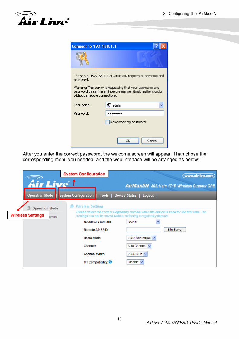
� Operation Mode: This menu is where you will find wireless and WAN settings. The AirMax5N’s wireless settings are dependent on the wireless operation mode you choose; only the applicable wireless settings for selected operation mode are shown. For example; WAN port setting is available only for AP Router and WISP Router mode, it will only be shown in those modes. To access wireless settings, click on the “Setup” button within each operation mode. For explanation on different wireless modes, please refer to Chapter 1. We will talk about functions in this menu for this chapter.
� System Configuration: All settings besides Wireless and WAN functions are in this category. The system configuration including changing password, upload firmware, backup configuration, settings PING watchdog, and setting management interface. We will talk about this menu’s function in Chapter 5.
� Device Status: This section for monitoring the status of AirMax5N. It provides information on device status, Ethernet status, wireless status, wireless client table, and system log.
� Logout: Please make sure to Logout after you finish all settings.
4.2 Operation Modes (Wireless and WAN Settings)
The wireless settings of AirMax5N are dependent on the wireless operation mode you choose. Therefore, the first step is to choose the operation mode. For explanation on when to use what operation mode, please refer to Chapter 1.
When you select “Wireless Settings” in the welcome screen, or click on the “Operation Mode” on the top menu; the following screen will appear:
This tells you what is the Current Operation Mode
Configure Wireless and WAN Settings
After you select the new operation mode, click here to Change.
Select one of the wireless operation modes here

4. Web Management-Wireless and WAN Settings
AirLive AirMax5N/ESD User’s Manual 25
� Mode: The available wireless operation modes for AirMax5N. Select one and click on “Change Mode” button to switch between modes.
� Setup: Click here to configure the Wireless and WAN (in router mode) settings.
� Radio: This explain how the radio function in the particular operation mode
� Ethernet: This shows whether the radio
Once you click on the “Setup” page, the wireless settings will appear.
4.2.1 Network SSID
Operation Mode -> Setup -> Network SSID
The SSID is the network name used to identify a wireless network. The SSID must be the same for all devices in the same wireless network. In AirMax5N; it is possible to create more than one SSID in AP, WDS + AP and AP Router mode, please check the “Multiple SSID ” section in this chapter. Conversely, several access points on a network can have the same SSID. The SSID length is up to 32 characters. The default SSID is “airlive”.
� Enable Wireless: The default wireless is on. You can uncheck this box to disable wireless interface.
� Disable SSID Broadcast: If you check this box, the SSID will be hidden; only users who know the SSID can associate with this network.

4. Web Management-Wireless and WAN Settings
AirLive AirMax5N/ESD User’s Manual 26
4.2.2 Site Survey
Operation Mode -> Setup -> Site Survey
The Site Survey function in AirMax5N provides 4 important functions
� In Client and Bridge Infrastructure mode, site survey will scan for available AP network. Then allow user to select and connect to the AP. This greatly simplify the installation
� Once Site Survey displays the available AP or Bridge networks, you can also check the signal strength to a particular SSID. Check the signal can be helpful for antenna alignment.
� For WDS Bridge mode, the Site Survey will scan for available AP and Bridge networks. User can then find the MAC address (BSSID) of the remote Bridges.
� For AP and AP router mode, the Site Survey allows administrator to check what channels are already occupied for choosing a cleaner channel.
When you click on Site Survey, the following screen will appear. It might take a few minutes to scan all the channels in the 5GHz spectrum.

4. Web Management-Wireless and WAN Settings
AirLive AirMax5N/ESD User’s Manual 27
� Add (to WDS): Please choose a SSID before click on this button. This button is available only in Client, WDS or WDS + AP modes. Once you click on this button, AirMax5N will attempt to make a connection with the selected network. If there is encryption needed, the AirMax5N will prompt you to enter the encryption key. Please make sure you enter the correct encryption key, the AirMax5N will not check whether the encryption key is correct.
� Signal Strength: This is a value to show the signal level of the AirMax5N. In general, remote APs with stronger signal will display higher level.
4.2.3 Radio Mode (11a, 11a/n mixed, 11n)
Operation Mode -> Setup -> Radio Mode AirMax5N has 3 different options for WLAN transmission.
4.2.4 Channel
Operation Mode -> Setup -> Channel The channel available for use in your device depends on your country’s regulations. This is subject to change depending on regulations of your country. Your device is preloaded with firmware according to the regulations. If your device’s firmware is not conforming to your country’s latest regulation, please write to [email protected].
4.2.5 Channel Width
Operation Mode -> Setup -> Channel Width Each channel will jump by number of 4 (i.e. 36, 40, 44…etc). You can change the Channel Width to 20 or 20/40MHz to either increase performance or reduce the interference problem.
Click here to select SSID for Association or Signal Survey
To connect with the selected SSID. This function is available only in Client or Bridge Mode
For antenna alignment. It will display signal value once a second.

4. Web Management-Wireless and WAN Settings
AirLive AirMax5N/ESD User’s Manual 28
4.2.6 Data Rate
Operation Mode -> Setup -> Data Rate Use this function; you can lock the data rate of your AirMax5N to a specified value. For 802.11a radio mode, the date rate supports from 1Mbps to 54Mbps. To 802.11n, the data rate will be specified in MCS value. For AirMax5N is a 1T1R wireless AP, is will support from MCS0 to MCS7.
4.2.7 Security Settings
Operation Mode -> Setup -> Security Settings Security settings allow you to use encryption to secure your data from eavesdropping. You can select different security policy to provide association authentication and/or data encryption. The AirMax5N features various security policies including WEP, 802.1x, WPA-RADIUS, WPA-PSK, WPA2-RADIUS, WPA2-PSK, and WPA-PSK. Please note not all security policies are available in all operation modes. All wireless devices on the same network must use the same security policy. We recommend using WPA-PSK or WPA2-PSK whenever possible. For WDS Bridge, we recommend using AES encryption.
WEP
WEP Encryption is the oldest and most available encryption method. However, it is also the least secure.
� Select one of the WEP key for wireless network: There are total of 4 possible keys for WEP encryption. You need to choose which key will be used for encryption. All wireless devices on the same network have to use the same settings. We recommend using WEP Key 1 as in default setting.
� WEP Keys: Please enter the WEP keys used for encryption. You need to fill at least the “Select WEP Key”. For example; if you choose “Select one of the WEP keys for the wireless network: Key 1” in the previous field, then it is necessary to fill WEP Key 1. The restriction to the Key length is depending on the Key type you selected.

4. Web Management-Wireless and WAN Settings
AirLive AirMax5N/ESD User’s Manual 29
� Hex: The Key length can be 10 or 26 character to Hex Key type, and the character can be 1~0, and A~F. If the Key length is not 10 nor 26, the alert message should pop up as below:
� ASCII: The Key length can be 5 or 13 character to ASCII Key type, and the character can be any ASCII character. If the length is not 5 nor 13, the alert message should pop up as below:
802.1x

4. Web Management-Wireless and WAN Settings
AirLive AirMax5N/ESD User’s Manual 30
802.1x allows users to leverage a RADIUS server to do association authentications. You can also enable dynamic WEP key (128 bit) to have data encryption. You do not have to enter the WEP key manually because it will be generated automatically and dynamically.
WPA-RADIUS, WPA2-RADIUS
Wi-Fi Protected Access (WPA) introduces the Temporal Key Integrity Protocol (TKIP) that provides added security. WPA2 adds full support for 802.11i standard and the CCMP (AES Encryption). ll 2 requires a RADIUS server available in order to do authentication (same as 802.1x), thus there is no shared key required.

4. Web Management-Wireless and WAN Settings
AirLive AirMax5N/ESD User’s Manual 31
� Encryption Type: There are two encryption types TKIP and AES (CCMP). While AES provides better security than TKIP, some wireless client stations may not be equipped with the hardware to support it. You can select TKIP/AES to allow TKIP clients and AES clients to connect to the Access Point at the same time.
� Key Renewal Interval: A group key is used for multicast/broadcast data, and the re-key interval is time period that the system will change the group key periodically. The shorter the interval is, the better the security is. The default is 3600 sec.
WPA-PSK, WPA2-PSK
Wi-Fi Protected Access (WPA) with Pre-Shared Key (PSK) provides better security than WEP keys. It does not require a RADIUS server in order to provide association authentication, but you do have to enter a shared key for the authentication purpose. The encryption key is generated automatically and dynamically. WPA2-PSK adds CCMP and AES encryption for even better security.

4. Web Management-Wireless and WAN Settings
AirLive AirMax5N/ESD User’s Manual 32
� Pre-shared Key: This is an ASCII string with 8 to 63 characters. Please make sure that both the AIRMAX5N and the wireless client stations use the same key.
� Encryption Type: There are two encryption types TKIP and AES (CCMP). While AES provides better security than TKIP, some wireless client stations may not be equipped with the hardware to support it. You can select TKIP/AES to allow TKIP clients and AES clients to connect to the Access Point at the same time.
� Key Renewal Interval: A group key is used for multicast/broadcast data, and the re-key interval is time period that the system will change the group key periodically. The shorter the interval is, the better the security is. The default is 3600 sec.

4. Web Management-Wireless and WAN Settings
AirLive AirMax5N/ESD User’s Manual 33
4.2.8 Antenna Settings
Operation Mode -> Setup -> Antenna Settings
� The AirMax5N is equipped with a 16dBi patch antennas. If it’s not enough for your application, you can also select a external antenna for making the radio signal be propagated further.
4.2.9 Transmit Power
Operation Mode -> Setup -> Transmit Power You can adjust the transmit output power of the AirMax5N’s radio from 5% to 10%. The higher the output power, the more distance AirMax5N can deliver. However, it is advised that you use just enough output power so it will not create excessive interference for the environment. Also, using too much power at close distance can create serious performance drop due to signal distortion.
4.2.10 Advance Settings (Wireless)
Operation Mode -> Setup -> Advance Settings This page includes all the wireless settings that change the RF behaviors of AirMax5N. It is important to read through this section before attempting to make changes.

4. Web Management-Wireless and WAN Settings
AirLive AirMax5N/ESD User’s Manual 34
� Beacon Interval: Beacon Interval: The device broadcasts beacon frames regularly to announce its existence. The beacon Interval specifies how often beacon frames are transmitted in time unit of milliseconds. The default value is 100, and a valid value should be between 1 and 65,535.
� RTS Threshold: RTS/CTS frames are used to gain control of the medium for
transmission. Any unicast (data or control) frames larger than specified RTS threshold must be transmitted following the RTS/CTS handshake exchange mechanism. The RTS threshold should have a value between 256-2347 bytes, with a default of 2347. It is recommended that this value does not deviate from the default too much.
� Fragmentation: When the size of a unicast frame exceeds the fragmentation
threshold, it will be fragmented before the transmission. It should have a value of 256-2346 bytes, with a default of 2346. If you experience a high packet error rate, you should slightly decrease the Fragmentation Threshold.
� DTIM Interval: The AIRMAX5N buffers packets for stations that operate in the
power-saving mode. The Delivery Traffic Indication Message (DTIM) informs such power-conserving stations that there are packets waiting to be received by them. The DTIM interval specifies how often the beacon frame should contain DTIMs. It should have a value between 1 to 255, with a default value of 3.
� TX Burst: AirMax5N will try to send a serial of packages with single ACK reply from
the clients. Enable this function to apply it.
4.2.11 Access Control (ACL)
Operation Mode -> Setup -> Access Control
The AIRMAX5N allows you to define a list of MAC addresses that are allowed or denied to access the wireless network. This function is available only for Access Point and AP Router modes.

4. Web Management-Wireless and WAN Settings
AirLive AirMax5N/ESD User’s Manual 35
� Disable MAC address control list: When selected, no MAC address filtering will be performed.
� Enable GRANT address control list: When selected, data traffic from only the specified devices in the table will be allowed in the network.
� Enable DENY address control list: When selected, data traffic from the devices specified in the table will be denied/discarded by the network.
To add a MAC address into the table, enter a Mnemonic Name and the MAC Address, and then click Add. The table lists all configured MAC Filter entries.
To delete entries, check the corresponding Select boxes and then press Delete Selected.
4.2.12 Multiple SSID
Operation Mode -> Setup -> Multiple SSID
This function is available only for Access Point and AP Router modes. Multiple SSID allows AirMax5N to create up to 4 different wireless networks (SSID). It is also known as “Virtual AP” function. Each SSID can have its Encryption type.

4. Web Management-Wireless and WAN Settings
AirLive AirMax5N/ESD User’s Manual 36
Configuring the Multiple SSID
When you click on the “Multiple SSID” button, the following screen will appear
How to add a SSID
You can add up to 4 SSID in AirMax5N. Please follow the procedure below:
1. Enter the SSID name (i.e. airlive1) and check if you needed to hide the SSID.
2. Click on “Apply” to add SSID
3. Go to the Security setting and select the SSID
4. Select the Security Policy (i.e. WPA2-PSK), and enter the Security Key (i.e. 12345678).
2
1

4. Web Management-Wireless and WAN Settings
AirLive AirMax5N/ESD User’s Manual 37
4.2.13 WMM QoS
Operation Mode -> Setup -> WMM QoS
Wi-Fi Multimedia (WMM) is a standard to prioritize traffic for multimedia applications. The
WMM Settings is to specify parameters on multiple data queue for better performance of
differentiated wireless traffic like Voice-over-IP (VoIP), other types of audio, video, and
streaming media as well as traditional IP data over the AP.
3
4

4. Web Management-Wireless and WAN Settings
AirLive AirMax5N/ESD User’s Manual 38
Configure the WMM QoS Parameters
� AC Type
The queue and associated priorities and parameters for transmission are as follows:
� AC_BE: Medium priority queue, medium throughput and delay. Most traditional
IP data is sent to this queue.
� AC_BK: Lowest priority queue, high throughput. Bulk data that requires
maximum throughput and is not time-sensitive is sent to this queue (FTP data,
for example):
� AC_VI: High priority queue, minimum delay. Time-sensitive data such as Video
and other streaming media are automatically sent to this queue.
� AC_VO: Highest priority queue, minimum delay. Time-sensitive data such as
Voice over IP (VoIP) is automatically sent to this queue.
Packets in a higher priority queue will be transmitted before packets in a lower
priority queue.

4. Web Management-Wireless and WAN Settings
AirLive AirMax5N/ESD User’s Manual 39
� CWmin and CWmax
If an access point detects that the medium is in use, it uses the DCF random backoff
timer to determine the amount of time to wait before attempting to access a given
channel again. Each access point waits some random period of time between retries.
The wait time (initially a random value within a range specified as the Minimum
Contention Window increases exponentially up to a specified limit Maximum
Contention Window.
The random delay avoids most of the collisions that would occur if multiple APs got
access to the medium at the same time and tried to transmit data simultaneously. The
more active users you have on a network, the more significant the performance gains
of the backoff timer will be in reducing the number of collisions and retransmissions.
The random backoff used by the access point is a configurable parameter. To describe the random delay, a "Minimum Contention Window" (CWMin) and a "Maximum Contention Window" (CWMax) is defined.
� CWmin: The value specified for the Minimum Contention Window is the upper
limit of a range for the initial random backoff wait time. The number used in the
random backoff is initially a random number between 0 and the number defined
for the Minimum Contention Window.
� CWmax: If the first random backoff time ends before successful transmission of
the data frame, the access point increments a retry counter, and doubles the
value of the random backoff window. The value specified in the Maximum
Contention Window is the upper limit for this doubling of the random backoff.
This doubling continues until either the data frame is sent or the Maximum
Contention Window size is reached.

4. Web Management-Wireless and WAN Settings
AirLive AirMax5N/ESD User’s Manual 40
� AIFSN
The Arbitration Inter-Frame Spacing (AIFs) specifies a wait time (in milliseconds) for
data frames. 802.11e uses interframe spaces to regulate which frames get access to
available channels and to coordinate wait times for transmission of different types of
data. The AIFs ensures that multiple access points do not try sending data at the same
time but instead wait until a channel is free. Valid values for AIFs are 1 through 255.
� Transmission Opportunity
The Transmission Opportunity (TXOP) is an interval of time when a WMM client station
has the right to initiate transmissions onto the wireless medium. This value specifies (in
milliseconds) the Transmission Opportunity (TXOP) for client stations; that is, the
interval of time when a WMM client station has the right to initiate transmissions on the
wireless network.
We recommend that you use the default settings on the WMM QoS page. Changing these values can lead to unexpected blockages of traffic on your wireless LAN, and the blockages might be difficult to diagnose.
4.2.14 Bandwidth Control
Operation Mode -> Setup -> Bandwidth Control
Bandwidth Control can limit the maximum speed of individual device. It is also known as Traffic Shaping. The AirMax5N provides Per-IP Bandwidth Control for both uplink and downlink speed. It controls the speed of both wireless and wired interface.

4. Web Management-Wireless and WAN Settings
AirLive AirMax5N/ESD User’s Manual 41
To configure, please click on the “Bandwidth Control” button under wireless settings. The following screen will appear:
� Enable: Seleck to enable Bandwidth Control. The default value is disabled.
� Local IP Address: Fill in the local IP address
� Uplink Bandwidth: Input uplink Maximum upload bandwidth
� Downlink Bandwidth: Input downlink Maximum upload bandwidth.
4.3 WDS Settings
Operation Mode -> Setup -> WDS Settings
WDS Bridge mode can make Point-to-Point and Multi-Point connections. Because of its faster performance, it is frequently used to build point-to-point bridge connection and backbone networks. In a WDS network, each node can have up to 4 connections. However, the total number of devices in a WDS network should not exceed 8.
In this section, we will talk about the WDS Settings which is available only in WDS Bridge mode. WDS Bridges are using BSSID (AP’s Wireless MAC address) to authenticate each other. Therefore, it is necessary to know the remote Bridge’s wireless MAC addresses. You can always do a “Site Survey” to find out the MAC Addresses.
When you click on WDS settings, the following screen will appear:
4. Web Management-Wireless and WAN Settings
AirLive AirMax5N/ESD User’s Manual 42
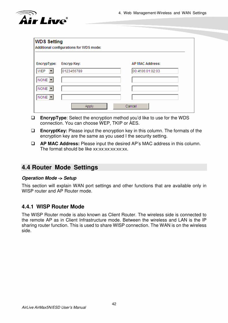
� EncrypType: Select the encryption method you’d like to use for the WDS connection. You can choose WEP, TKIP or AES.
� EncryptKey: Please input the encryption key in this column. The formats of the encryption key are the same as you used I the security setting.
� AP MAC Address: Please input the desired AP’s MAC address in this column. The format should be like xx:xx:xx:xx:xx:xx.
4.4 Router Mode Settings
Operation Mode -> Setup
This section will explain WAN port settings and other functions that are available only in WISP router and AP Router mode.
4.4.1 WISP Router Mode
The WISP Router mode is also known as Client Router. The wireless side is connected to the remote AP as in Client Infrastructure mode. Between the wireless and LAN is the IP sharing router function. This is used to share WISP connection. The WAN is on the wireless side.

4. Web Management-Wireless and WAN Settings
AirLive AirMax5N/ESD User’s Manual 43
4.4.2 AP Router Mode
In AP Router mode, the non-POE port of the AirMax5N will turn into the WAN port. The wireless interface will become the LAN side. It will turn AirMax5N into a wireless router. Since the Ethernet interface becomes WAN; the POE port also stands on the LAN side, and you can manage your AP via the POE port.
When you select the WISP Router or AP Router mode, additional wireless settings will appear for WAN port settings.
4.4.3 WAN Port Settings
Operation Mode -> Setup -> WAN Port Settings
The AirMax5N support different authentication and IP assignment standards for the WAN port. It includes fixed IP, DHCP, PPPoE, PPTP and L2TP protocols. Please consult with your ISP about what authentication type is used for the WAN port connection.
WAN
LAN

4. Web Management-Wireless and WAN Settings
AirLive AirMax5N/ESD User’s Manual 44
� Clone MAC Address: Some service provider (Cable Modem provider) lock to certain MAC address. In this situation, the WAN port of AirMax5N needs to clone the MAC address. Please check the “Clone MAC address” box and enter the address that need to be cloned.
4.4.4 Dynamic DNS Settings
Operation Mode -> Setup -> Dynamic DNS Settings
Dynamic DNS (DDNS) allows you to create a hostname that points to your dynamic IP or
static IP address or URL. AirMax5N provide Dynamic DNS client using DynDNS, please
visit http://www.dyndns.org for detail.
4.4.5 Remote Management Settings
Operation Mode -> Setup -> Remote Management Remote Management allows administrator to manage the AirMax5N from WAN side. You can enable or disable.

4. Web Management-Wireless and WAN Settings
AirLive AirMax5N/ESD User’s Manual 45
� HTTP Web Server Access: You can enable or disable HTTP service from WAN side
� Response to WAN ping: You can disable or enable whether AirMax5N will response to PING command.
4.4.6 DHCP Server
Operation Mode -> Setup -> DHCP Server Settings
DHCP Server Settings is to assign private IP address to the devices in your local area
network (LAN). The default LAN IP address of AirMax5N is 192.168.1.1, changing
AirMax5N’s IP address will also change the DHCP server’s IP subnet.

4. Web Management-Wireless and WAN Settings
AirLive AirMax5N/ESD User’s Manual 46
4.4.7 DMZ
Operation Mode -> Setup ->DMZ Settings
DMZ opens all TCP/UDP ports to particular IP address on the LAN side. It allows setting up servers behind the AirMax5N.
Enable the DMZ function and then enter the local DMZ IP address. A DMZ server is a common term used to describe the default virtual server. If the DMZ server is selected, Internet traffic not destined for a valid virtual server is redirected to this privately addressed LAN client. This can be used together with a separate firewall device to perform additional security functions.
4.4.8 IP Routing Settings
Operation Mode -> Setup -> IP Routing Settings The IP Routing Settings allows you to configure routing feature in the gateway � Dynamic Routing: Select the routing protocol scheme used for the router’s LAN / WAN port. � Static Routing: This allows you to manually configure static network routes. Static routes will override routes learned by standard routing protocol discover methods. � IP Routing Table: To delete a static route from the table, select the route and click Delete Selected.

4. Web Management-Wireless and WAN Settings
AirLive AirMax5N/ESD User’s Manual 47

4. Web Management-Wireless and WAN Settings
AirLive AirMax5N/ESD User’s Manual 48
4.4.9 Virtual Server Settings
Operation Mode -> Setup ->Virtual Setting This allows you to specify one or more applications running on server computers on the LAN that may be accessed by any Internet user. Internet data destined for the specified public port will be directed to the specified private port number on the LAN client with the specified private IP address.
4. Web Management-Wireless and WAN Settings
AirLive AirMax5N/ESD User’s Manual 49
4.4.10 IP Filtering Settings
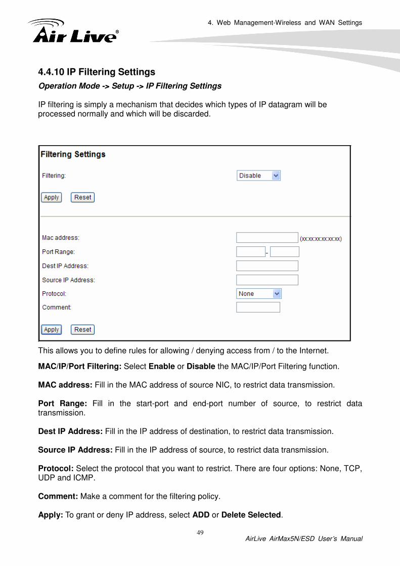
Operation Mode -> Setup -> IP Filtering Settings IP filtering is simply a mechanism that decides which types of IP datagram will be processed normally and which will be discarded.
This allows you to define rules for allowing / denying access from / to the Internet.
MAC/IP/Port Filtering: Select Enable or Disable the MAC/IP/Port Filtering function. MAC address: Fill in the MAC address of source NIC, to restrict data transmission. Port Range: Fill in the start-port and end-port number of source, to restrict data transmission. Dest IP Address: Fill in the IP address of destination, to restrict data transmission. Source IP Address: Fill in the IP address of source, to restrict data transmission. Protocol: Select the protocol that you want to restrict. There are four options: None, TCP, UDP and ICMP. Comment: Make a comment for the filtering policy. Apply: To grant or deny IP address, select ADD or Delete Selected.

5. Web Management 2: System Configuration and Status
AirLive AirMax5N/ESD User’s Manual 50
In this chapter, we will explain about System Configurations in web management interface. Please be sure to read through Chapter 3’s “Introduction to Web Management” and “Initial Configurations” first. .
5.1 System Configuration
When you click on the “System Configuration” menu on the top menu bar, the following screen will appear. The system configuration includes all non-wireless settings. We will explain their functions here.
5.1.1 Device IP Settings
System Configurations>> Device IP Settings
The Device IP Settings screen allows you to configure the IP address and subnet of the device. Although you can rely on a DHCP server to assign an IP address to the AIRMAX5N automatically, it is recommended that you configure a static IP address manually in most applications.
5 5. Web Management 2:
System Configuration and Status

5. Web Management 2: System Configuration and Status
AirLive AirMax5N/ESD User’s Manual 51
Assign Static IP to the Device
If you choose to assign the IP address manually, enable the checkbox of “Assign static IP to this device” and then fill in the following fields
� IP Address and IP Subnet Mask: Default values are 192.168.1.1 and 255.255.255.0 respectively. It is important to note that there are similar addresses falling in the standard private IP address range and it is an essential security feature of the device. Because of this private IP address, the device can no longer be accessed (seen) from the Internet.
� Gateway IP Address: Enter the IP address of your default gateway.
� DNS Server: The Domain Name System (DNS) is a server on the Internet that translates logical names such as “www.yahoo.com” to IP addresses like 66.218.71.80. In order to do this, a query is made by the requesting device to a DNS server to provide the necessary information. If your system administrator requires you to manually enter the DNS Server addresses, you should enter them here.
� Click APPLY to go to the next screen.
Use DHCP Client Protocol to Get IP automatically
If you choose to use a DHCP Server to acquire an IP address for the AIRMAX5N automatically, enable the checkbox “Use the DHCP client protocol to automatically get the IP address for this device”. Then click Apply to the next screen. As a reminder, you might loss the IP address of AirMax5N when IP is assigned dynamically.

5. Web Management 2: System Configuration and Status
AirLive AirMax5N/ESD User’s Manual 52
5.1.2 Time Settings
System Configuration ->Time Settings
It is important that you set the date and time for your AirMax5N so that the system log will record the correct date and time information. We recommend you choose “Enable NTP” so the time will be keep even after reboot. If your AirMax5N is not connected to Internet, please enter the time manually. Please remember to select your local time zone and click “Apply” to finish.
5.1.3 Password Settings
System Configuration ->Time Settings
To change password, please go to “System Configuration” -> “Password Settings” menu.

5. Web Management 2: System Configuration and Status
AirLive AirMax5N/ESD User’s Manual 53
5.1.4 System Management
System Configuration -> System Management
In this page, administrator can change the management parameters and disable/enable management interface.
� Telnet: Administrator can enable or disable the telnet interface here.
� UPnP: Administrator can enable or disable the UPnP function here.
� Syslog: To enable or disable the syslog here.
5.1.5 Ping Watchdog
System Configuration -> Ping Watchdog The Ping Watchdog will ping remote IP addresses to make sure the wireless connection is active, if not, it can either reconnect or reboot.

5. Web Management 2: System Configuration and Status
AirLive AirMax5N/ESD User’s Manual 54
� PING Frequency: means "How often the CPE will PING". For example, it will PING
once every "120" seconds. � Fail Tries means "How many times fails before the CPE will judge the PING failed".
For example "2" means the CPE will reconnect if the PING doesn't respond for 2 times. When you set the Ping Frequency to every "120" seconds and Fail Tries to "2". It means the CPE will ping every 120 seconds, after the second failure, it will reconnect.
Actions:
� Reconnect: the AirMax5N will attempt to re-establish the connection. It is recommend to use this option for WDS Bridge connection.
� Reboot: the AirMax5N will do a power recycle.
5.1.6 Firmware Upgrade
System Configuration -> Firmware Upgrade You can upgrade the firmware of your AIRMAX5N (the software that controls your AIRMAX5N’s operation). Normally, this is done when a new version of firmware offers new features that you want, or solves problems that you have encountered with the current version.

5. Web Management 2: System Configuration and Status
AirLive AirMax5N/ESD User’s Manual 55
� Upgrade Firmware:
To update the AIRMAX5N firmware, first download the firmware from AirLive web site to your local disk, and then from the above screen enter the path and filename of the firmware file (or click Browse to locate the firmware file). Next, Click the Upgrade button to start.
The new firmware will be loaded to your AIRMAX5N. After a message appears telling you that the operation is completed, you need to reset the system to have the new firmware take effect.
Do not power off the device while upgrading the firmware. It is recommended that you do not upgrade your AIRMAX5N unless the new firmware has new features you need or if it has a fix to a problem that you’ve encountered. For the data structure might be change after firmware upgrade, it’s better for the administrator to reset the device to factory default for cleaning the original configuration data.
5.1.7 Configuration Save and Restore
System Configuration -> Configuration Save and Restore
You can save system configuration settings to a file, and later download it back to the AIRMAX5N by following the steps.

5. Web Management 2: System Configuration and Status
AirLive AirMax5N/ESD User’s Manual 56
Step 1 Select Configuration Save and Restore from the System Configurations menu.
Step 2 Click the SAVEbutton to save the current configuration into the specified file.
Or click the Browse button to locate the configuration file ,then click the RESTORE button to restore the system configuration from the specified file.
5.1.8 Factory Default
System Configuration -> Factory Default
You can reset the configuration of your AIRMAX5N to the factory default settings.
Step 1 Select Factory Default from the System Configuration menu.
Step 2 Click YES to go ahead and restore the configuration to the factory default.

5. Web Management 2: System Configuration and Status
AirLive AirMax5N/ESD User’s Manual 57
5.2 Device Status
When you click on the “Device Status” on the top menu bar, the sub menu for device status will appear.
5.2.1 Device Information
This page shows the general information about AirMax5N such as firmware version, device IP/MAC, WAN IP/MAC(in router modes), Gateway IP(in router modes), DNS IP…etc. Below are some additional explanations on some status information of this page:
� CPU Loading Display the CPU usage.
� Memory Information Display how much memory is used and free.
� Firmware version: Shows the current firmware version installed in this AirMax5N
� Wireless MAC: This is the wireless MAC address (BSSID) of this AiMax5N.
� Uptime: This is the time that the AirMax5N has been running since last power up.
� ARP Table: Display the corresponding IP and MAC address Table.

0 Web Management 2: System Configuration and Status
AirLive AirMax5N/ESD User’s Manual 58
5.2.2 Wireless Information
This page shows the information about wireless status such as current operation mode, wireless traffic, error packets, device’s BSSD, connecting State, channel, and encryption used.
5.2.3 Internet Information
This page shows the information about WAN port of the AirMax5N. It includes the type of
WAN port authentication used and the IP address information about the WAN port.

5. Web Management 2: System Configuration and Status
AirLive AirMax5N/ESD User’s Manual 59
5.2.4 Wireless Client Table
This function displays the information about wireless clients that are associated with
AirMax5N. It includes signal strength, TX and RX data rate, MAC address, and the state.
5.2.5 System Log
The System Log displays the system activities, login, and system error report. If you need
to report a problem to Air Live, please be sure to send us the System Log information also.

6. Antenna Alignment
AirLive AirMax5N/ESD User’s Manual 60
It is important to align your antenna correctly with the remote device to get the best signal and performance. The AirMax5N is equipped with a 16dBi antenna. There is a connector for external antenna if more distance or different angle coverage is required. In this chapter, we will first explain the design and function of the built-in antenna.
We will provide instructions on the two alignment methods later in this chapter. It is recommended that you read through 4.2.12 on how to change antenna settings, and 4.2.20 about the RSSI LED Threshold before reading this chapter.
6.1 About AirMax5N’s Antenna
The AirMax’s built-in antenna has the following characteristics:
� Gain: 16dBi � Type: Patch Antenna � Vertical Coverage Angle: 20 degree forward � Horizontal Coverage Angle: 30 degree forward � External Antenna Connector: R-SMA
6.1.1 Mounting Adjustment
The degree you can adjust the AirMax5N’s antenna depends on what mounting kit you use. Using the standard strap mount allows you to rotate the CPE in the horizontal plane only. As long as 2 wireless devices are at about the same elevation, this adjustment is already enough.
6.2 Preparation before Installation
The antenna alignment is for small adjustment only, you should not use it find remote AP. The correct way is to use a Graphic Information System (GIS) program such as “Google Earth” to find the locations of the installation site and the nearest AP/Bridge. Then measure the approximate direction and angle. It will also help to bring a pair of hi power binocular for sight survey.
66. Antenna Alignment

6. Antenna Alignment
AirLive AirMax5N/ESD User’s Manual 61
6.3 Antenna Alignment using Signal Survey
Signal Survey function can display the Signal Strength value in real time to help you with antenna alignment. The Signal Survey is a subnet of the Site Survey function; you do not need to enter the wireless settings in advance. Please follow the example below to complete antenna alignment using Signal Survey function.
SSID: airlive3 Encryption: WPA-PSK
3 km

6. Antenna Alignment
AirLive AirMax5N/ESD User’s Manual 62
Step 1 Go to the Sit Survey function
Step 2 Check the Signal Strength of the desired AP. For identify the AP quicker, we suggest you to written the MAC address of the desired AP and using the MAC to filter out your target.
Step 3 If the Signal Strength is too weak to make a connection, please adjust the antenna.
Step 4 Refresh the Site Survey page and check the Signal Strength again.
Step 5 Once the Signal is good enough, please check the radio box in front of the desired AP and then click on the ASSOCIATE button for building the connection.

7. Application Example: Infrastructure
AirLive AirMax5N/ESD User’s Manual 63
In this chapter, you will learn how to utilize AirMax5N’s Access Point mode, Client Infrastructure Mode, and Bridge Infrastructure mode in one application example. In addition, you will also learn how to configure multiple SSID.
7.1 Application Environment
In this application example, an AirMax5N in Access Point mode is in the center of an infrastructure topology with two virtual wireless networks. Each wireless network has its own SSID, security Policy and Bandwidth policy. Below is the general description about the devices of the network.
Central AP: AirMax5N in Access Point Mode
� Using multiple SSID to create 2 wireless network
� AirLive01: A network for another CPE with WPA-PSK security policy.
� AirLive02: A network for wireless station with WPA-PSK2 security policy
Client: AirMax5N in Client Mode
� Associate the AirLive01 and share the bandwidth to remote LAN
7 7. Application Example:
Infrastructure

7. Application Example: Infrastructure
AirLive AirMax5N/ESD User’s Manual 64
7.2 Central AP: Access Point Mode
The configuration of Central AP involves the followings:
� Using multiple SSID to create 2 wireless network
� AirLive01: A network for remote AP with WPA-PSK security policy.
� AirLive02: A network with WPA-PSK2 security policy
7.2.1 AP Wireless Settings
AP : AirMax5N in AP Mode
� Set device IP to 192.168.1.1 with subnet mask of 255.255.255.248
� Connect to the Access Point using AP mode.

7. Application Example: Infrastructure
AirLive AirMax5N/ESD User’s Manual 65
Step 1 Click on “setup” button on the “Operation Mode” page
Step 2 On the wireless setting page, please enter the SSID and Channel. And then press
“Apply” to make changes.

7. Application Example: Infrastructure
AirLive AirMax5N/ESD User’s Manual 66
Step 3 Click on the “Multiple SSID”.
Step 4 Go to the Security Setting and set the security policy separately.
2000

7. Application Example: Infrastructure
AirLive AirMax5N/ESD User’s Manual 67
7.3 Client: Client Mode
Client : AirMax5N in Client Infrastructure Mode
� Set device IP to 192.168.1.100 with subnet mask of 255.255.255.248
� Connect to the Access Point using Client mode.
� Use Site Survey to connect and associate with the AP.
7.3.1 Device C IP Address
Step 1 Go to “System Configuration -> Device IP settings”. Select “Assign Static IP to this device”. Then enter the IP address and Subnet Mask as bellowed. Click Apply when finished.

7. Application Example: Infrastructure
AirLive AirMax5N/ESD User’s Manual 68
7.3.2 Client Wireless Settings
Step 1 Go to “Operation Mode” menu. Select “Client”, and then click on “Change Mode” button.
Step 2 Press “Setup” to enter the wireless settings page. Click on the Site Survey button for searching the remote AP.
2
1

7. Application Example: Infrastructure
AirLive AirMax5N/ESD User’s Manual 69
Step 3 After pressing “Site Survey” button, the following page should appear. Select “AirLive01” and press “Associate” button to connect
Step 4 The AirMax5N will prompt you to enter security policy information. Select WPA-PSK and enter your Pre-Shared Key.
Step 5 Click on “Apply”. After a few seconds, the following screen will appear to show successful connection.
You have now setup a successful Infrastructure network with AirMax5N in Access Point and Client modes

8. Specifications
AirLive AirMax5N/ESD User’s Manual 70
The specification of AirMax5N is subject to change without notice. Please use the information with caution.
8.1 Features
8.1.1 General Feature
� 1T1R 150Mbps � IEEE 802.11a/n � Runs from 5.1GHz to 5.8GHz Spectrum � 2 x 10/100 Ethernet Port with one Passive PoE port � Built-in 16dBi Antenna � Up to 25dBm Output Power Max(limited according to regulations in EU and U.S.) � AP, Bridge, Client, Router, WISP Modes � R-SMA Female Connector for External Antenna � Passive PoE Powered � Support Wireless Access Control, Client Isolation
8.2 Specifications
Hardware - 1T1R Wireless 802.11 a/n Standard - 2 x 10/100 Ethernet Port with one Passive PoE port - 4MB Flash, 32MB SDRAM - 12V Passive PoE (accept up to 18V) - Reset Button on PoE Injector Antenna Built-in Directional Antenna: 16dBi External (Optional): R-SMA Female Connector Frequency Band In 5GHz spectrum. Available frequency range varies according to the regulations in each country or region. Data Rate 802.11a: up to 54Mbps 802.11n (20MHz): up to 72Mbps 802.11n (40MHz): up to 150Mbps
8 8. Specifications

8. Specifications
AirLive AirMax5N/ESD User’s Manual 71
Power Supply - Power Adapter: 12V/1A - Advance Passive PoE (Accept 12 to 18 volts) - POE Adapter, DC Injector provided - POE port built-in on the PCB Transmission Rates - 802.11a: up to 54Mbps - 802.11n (20MHz): up to 72Mbps - 802.11n (40MHz): up to 150Mbps Media Access Control CSMA/CA Sensitivity - [email protected] - [email protected] Output Power (Limited according to regulation in EU and United States) 802.11a: up to 25± 1 dBm 802.11n: up to 22± 1 dBm Mode - AP, Bridge, Client, Router, WISP Modes Security - 64/128bit WEP - WPA (TKIP with IEEE 802.11x) - WPA2 (AES with IEEEE 802.11x) Software - Site Survey with RSSI Signal Survey - User Friendly Web Management - Channel list selection - Support adjustable output power - WEP over WDS support - Low Noise Amplifier (LNA) support - AP, Bridge, Client, Router, WISP Modes - Support DHCP Server, Client and Relay - Support Wireless Access Control, Client Isolation - Support Virtual Server, DMZ, Port Forwarding - Support Dynamic, Static IP, PPPoE, PPTP and L2TP - QoS bandwidth management - Software WPS function - Firewall, IP, Port, MAC and URL filtering - Support L2TP, IPSec, and PPTP VPN Pass through - Firmware upgrade and configuration backup via Web UI

8. Specifications
AirLive AirMax5N/ESD User’s Manual 72
Certificate - FCC, CE Product Size ( L x W x H (mm) ) - 220 x 80 x 35 mm
9. Wireless Network Glossary
AirLive AirMax5N/ESD User’s Manual 73
The wireless network glossary contains explanation or information about common terms used in wireless networking products. Some of information in this glossary might be outdated, please use with caution.
802.11a
An IEEE specification for wireless networking that operates in the 5 GHz frequency range
(5.425 GHz to 5.750 GHz) with a maximum of 54 Mbps data transfer rate. The 5 GHz
frequency band is not as crowded as the 2.4 GHz band. In addition, the 802.11a have 12
non-overlapping channels, comparing to 802.11b/g's 3 non-overlapping channels. This
means the possibility to build larger non-interfering networks. However, the 802.11a deliver
shorter distance at the same output power when comparing to 802.11g.
802.3ad
802.3ad is an IEEE standard for bonding or aggregating multiple Ethernet ports into one
virtual port (also known as trunking) to increase the bandwidth.
802.3af
This is the PoE (Power over Ethernet) standard by IEEE committee. 803.af uses 48V POE
standard that can deliver up to 100 meter distance over Ethernet cable.
802.11b
International standard for wireless networking that operates in the 2.4 GHz frequency band
(2.4 GHz to 2.4835 GHz) and provides a throughput up to 11 Mbps.
802.1d STP
Spanning Tree Protocol. It is an algorithm to prevent network from forming. The STP
protocol allows net work to provide a redundant link in the event of a link failure. It is advice
to turn on this option for multi-link bridge network.
9 9. Wireless Network
Glossary

9. Wireless Network Glossary
AirLive AirMax5N/ESD User’s Manual 74
802.11d
Also known as “Global Roaming”. 802.11d is a standard for use in countries where systems
using other standards in the 802.11 family are not allowed to operate.
802.11e
The IEEE QoS standard for prioritizing traffic of the VoIP and multimedia applications. The
WMM is based on a subset of the 802.11e.
802.11g
A standard provides a throughput up to 54 Mbps using OFDM technology. It also operates
in the 2.4 GHz frequency band as 802.11b. 802.11g devices are backward compatible with
802.11b devices.
802.11h
This IEEE standard define the TPC (transmission power control) and DFS(dynamic
frequency selection) required to operate WiFi devices in 5GHz for EU.
802.11i
The IEEE standard for wireless security. 802.11i standard includes TKIP, CCMP, and AES
encryption to improve wireless security. It is also know as WPA2.
802.11n
The IEEE 802.11 standard improves network throughput over 802.11a and 802.11g, with
a significant increase in the maximum data rate from 54 Mbps to 600 Mbps. 802.11n
standardized support for multiple-input multiple-output (MIMO) and frame aggregation, and
security improvements.
802.1Q Tag VLAN
In 802.1Q VLAN, the VLAN information is written into the Ethernet packet itself. Each
packet carries a VLAN ID(called Tag) as it traveled across the network. Therefore, the
VLAN configuration can be configured across multiple switches. In 802.1Q spec, possible
4096 VLAN ID can be created. Although for some devices, they can only view in frames of
256 ID at a time.

9. Wireless Network Glossary
AirLive AirMax5N/ESD User’s Manual 75
802.1x
802.1x is a security standard for wired and wireless LANs. In the 802.1x parlance, there are
usually supplicants (client), authenticator (switch or AP), and authentication server (radius
server) in the network. When a supplicants request a service, the authenticator will pass the
request and wait for the authentication server to grant access and register accounting. The
802.1x is the most widely used method of authentication by WISP.
Adhoc
A Peer-to-Peer wireless network. An Adhoc wireless network do not use wireless AP or
router as the central hub of the network. Instead, wireless client are connected directly to
each other. The disadvantage of Adhoc network is the lack of wired interface to Internet
connections. It is not recommended for network more than 2 nodes.
Access Point (AP)
The central hub of a wireless LAN network. Access Points have one or more Ethernet ports
that can connect devices (such as Internet connection) for sharing. Multi-function Access
Point can also function as an Ethernet client, wireless bridge, or repeat signals from other
AP. Access Points typically have more wireless functions comparing to wireless routers.
ACK Timeout
Acknowledgement Timeout Windows. When a packet is sent out from one wireless station
to the other, it will waits for an Acknowledgement frame from the remote station. The station
will only wait for a certain amount of time, this time is called the ACK timeout. If the ACK is
NOT received within that timeout period then the packet will be re-transmitted resulting in
reduced throughput. If the ACK setting is too high then throughput will be lost due to waiting
for the Ack Window to timeout on lost packets. If the ACK setting is too low then the ACK
window will have expired and the returning packet will be dropped, greatly lowering
throughput. By having the ability to adjust the ACK setting we can effectively optimize the
throughput over long distance links. This is especially true for 802.11a and 802.11g
networks. Setting the correct ACK timeout value need to consider 3 factors: distance, AP
response time, and interference. The AirMax5N provide ACK adjustment capability in form
of either distance or direct input. When you enter the distance parameter, the AirMax5N will
automatically calculate the correct ACK timeout value.

9. Wireless Network Glossary
AirLive AirMax5N/ESD User’s Manual 76
Bandwidth Management
Bandwidth Management controls the transmission speed of a port, user, IP address, and application. Router can use bandwidth control to limit the Internet connection speed of individual IP or Application. It can also guarantee the speed of certain special application or privileged IP address - a crucial feature of QoS (Quality of Service) function. The AirMax5N’s features both “Per-user Bandwidth Control” and “Total Bandwidth Control”. “Per-user Bandwidth Control” allow administrator to define the maximum bandwidth of each user by IP, IP Group, or MAC address. Total Bandwidth define the maximum bandwidth of wireless or Ethernet interface.
Bootloader
Bootloader is the under layering program that will start at the power-up before the device
loads firmware. It is similar to BIOS on a personal computer. When a firmware crashed, you
might be able to recover your device from bootloader.
Bridge
A product that connects 2 different networks that uses the same protocol. Wireless bridges
are commonly used to link network across remote buildings. For wireless application, there
are 2 types of Bridges. WDS Bridge can be used in Point-to-Point or Point-to-Multipoint
topology. Bridge Infrastructure works with AP mode to form a star topology.
Cable and Connector Loss: During wireless design and deployment, it is important to
factor in the cable and connector loss. Cable and connector loss will reduce the output
power and receiver sensitivity of the radio at connector end. The longer the cable length is,
the more the cable loss. Cable loss should be subtracted from the total output power during
distance calculation. For example, if the cable and connector loss is 3dBm and the output
power is 20dBm; the output power at the cable end is only 17dBm.
Client
Client means a network device or utility that receives service from host or server. A client
device means end user device such as wireless cards or wireless CPE.
CPE Devices
CPE stands for Customer Premises Equipment. A CPE is a device installed on the end
user's side to receive network services. For example, on an ADSL network, the ADSL
modem/router on the subscriber's home is the CPE device. Wireless CPE means a
complete Wireless (usually an AP with built-in Antenna) that receive wireless broadband
access from the WISP. The opposite of CPE is CO.

9. Wireless Network Glossary
AirLive AirMax5N/ESD User’s Manual 77
CTS
Clear To Send. A signal sent by a device to indicate that it is ready to receive data.
DDNS
Dynamic Domain Name System. An algorithm that allows the use of dynamic IP address for
hosting Internet Server. A DDNS service provides each user account with a domain name.
A router with DDNS capability has a built-in DDNS client that updates the IP address
information to DDNS service provider whenever there is a change. Therefore, users can
build website or other Internet servers even if they don't have fixed IP connection.
DHCP
Dynamic Hosting Configuration Protocol. A protocol that enables a server to dynamically
assign IP addresses. When DHCP is used, whenever a computer logs onto the network, it
automatically gets an IP address assigned to it by DHCP server. A DHCP server can either
be a designated PC on the network or another network device, such as a router.
DMZ
Demilitarized Zone. When a router opens a DMZ port to an internal network device, it opens
all the TCP/UDP service ports to this particular device. The feature is used commonly for
setting up H.323 VoIP or Multi-Media servers.
DNS
A program that translates URLs to IP addresses by accessing a database maintained on a
collection of Internet servers.
Domain Name
The unique name that identifies an Internet site. Domain Names always have 2 or more
parts, separated by dots. In www.airlive.com, the "airlive.com" is the doman name.
DoS Attack
Denial of Service. A type of network attack that floods the network with useless traffic. Many
DoS attacks, such as the Ping of Death and Teardrop attacks, exploit limitations in the
TCP/IP protocols.

9. Wireless Network Glossary
AirLive AirMax5N/ESD User’s Manual 78
Encryption
Encoding data to prevent it from being read by unauthorized people. The common wireless
encryption schemes are WEP, WPA, and WPA2.
ESSID (SSID)
The identification name of an 802.11 wireless network. Since wireless network has no
physical boundary liked wired Ethernet network, wireless LAN needs an identifier to
distinguish one network from the other. Wireless clients must know the SSID in order to
associate with a WLAN network. Hide SSID feature disable SSID broadcast,
so users must know the correct SSID in order to join a wireless network.
Firewall
A system that secures a network and prevents access by unauthorized users. Firewalls can
be software, router, or gateway. Firewalls can prevent unrestricted access into a network,
as well as restricting data from flowing out of a network.
Firmware
The program that runs inside embedded device such as router or AP. Many network
devices are firmware upgradeable through web interface or utility program.
FTP
File Transfer Protocol. A standard protocol for sending files between computers over a
TCP/IP network and the Internet.
Fragment Threshold
Frame Size larger than this will be divided into smaller fragment. If there are interferences
in your area, lower this value can improve the performance. If there are not, keep this
parameter at higher value. The default size is 2346. You can try 1500, 1000, or 500 when
there are interference around your network.
Full Duplex
The ability of a networking device to receive and transmit data simultaneously. In wireless
environment, this is usually done with 2 or more radios doing load balancing.

9. Wireless Network Glossary
AirLive AirMax5N/ESD User’s Manual 79
Gateway
In the global Internet network, the gateways are core routers that connect networks in
different IP subnet together. In a LAN environment with an IP sharing router, the gateway is
the router. In an office environment, gateway typically is a multi-function device that
integrates NAT, firewall, bandwidth management, and other security functions.
Hotspot
A place where you can access Wi-Fi service. The term hotspot has two meanings in
wireless deployment. One is the wireless infrastructure deployment; the other is the Internet
access billing system. In a hotspot system, a service provider typically need an
authentication and account system for billing purposes, and a wireless AP network to
provide access for customers.
IGMP Snooping
Internet Group Management Protocol (IGMP) is a Layer 3 protocol to report IP multicast
memberships to neighboring multicast switches and routers. IGMP snooping is a feature
that allows an Ethernet switch to "listen in" on the IGMP conversation between hosts and
routers. A switch support IGMP snooping has the possibility to avoid multicast traffic being
treated as broadcast traffic; therefore, reducing the overall traffic on the network.
Infrastructure Mode
A wireless network that is built around one or more access points to provide wireless clients
access to wired LAN / Internet service. The opposite of Infrastructure mode is Adhoc mode.
IP address
IP (Internet Protocol) is a layer-3 network protocol that is the basis of all Internet
communication. An IP address is 32-bit number that identifies each sender or receiver of
information that is sent across the Internet. An IP address has two parts: an identifier of a
particular network on the Internet and an identifier of the particular device (which can be a
server or a workstation) within that network. The new IPv6 specification supports 128-bit IP
address format.
IPsec
IP Security. A set of protocols developed by the IETF to support secure exchange of
packets at the IP layer. IPsec has been deployed widely to implement Virtual Private
Networks (VPNs). IPsec supports two encryption modes: Transport and Tunnel. Transport
mode encrypts only the data of each packet, but leaves the header untouched. The more
secure Tunnel mode encrypts both the header and the payload. On the receiving side, an
IPSec-compliant device decrypts each packet.

9. Wireless Network Glossary
AirLive AirMax5N/ESD User’s Manual 80
LACP (802.3ad) Trunking
The 802.3ad Link Aggregation standard defines how to combine the several Ethernet ports
into one high-bandwidth port to increase the transmission speed. It is also known as port
trunking. Both device must set the trunking feature to work.
MAC
Media Access Control. MAC address provides layer-2 identification for Networking Devices.
Each Ethernet device has its own unique address. The first 6 digits are unique for each
manufacturer. When a network device have MAC access control feature, only the devices
with the approved MAC address can connect with the network.
Mbps
Megabits Per Second. One million bits per second; a unit of measurement for data
transmission
MESH
Mesh is an outdoor wireless technology that uses Spanning Tree Protocol (STP) and
Wireless Distribution system to achieve self-forming, self-healing, and self-configuring
outdoor network. MESH network are able to take the shortest path to a destination that
does not have to be in the line of site.
MIMO
Multi In Multi Out. A Smart Antenna technology designed to increase the coverage and
performance of a WLAN network. In a MIMO device, 2 or more antennas are used to
increase the receiver sensitivity and to focus available power at intended Rx.
NAT
Network Address Translation. A network algorithm used by Routers to enables several PCs
to share single IP address provided by the ISP. The IP that a router gets from the ISP side
is called Real IP, the IP assigned to PC under the NAT environment is called Private IP.
Node
A network connection end point, typically a computer.

9. Wireless Network Glossary
AirLive AirMax5N/ESD User’s Manual 81
Packet
A unit of data sent over a network.
Passphrase
Used much like a password, a passphrase simplifies the WEP encryption process by
automatically generating the WEP encryption keys for the company products.
POE
Power over Ethernet. A standard to deliver both power and data through one single
Ethernet cable (UTP/STP). It allows network device to be installed far away from power
ource. A POE system typically compose of 2 main component: DC Injector (Base Unit) and
Splitter(Terminal Unit). The DC injector combines the power and data, and the splitter
separates the data and power back. A PoE Access Point or CPE has the splitter built-in to
the device. The IEEE 802.3af is a POE spec that uses 48 volt to deliver power up to 100
meter distance.
Port
This word has 2 different meaning for networking. � The hardware connection point on a computer or networking device used for plugging
in a cable or an adapter.
� The virtual connection point through which a computer uses a specific application on a
server.
PPPoE
Point-to- Point Protocol over Ethernet. PPPoE relies on two widely accepted standards:
PPP and Ethernet. PPPoE is a specification for connecting the users on an Ethernet to the
Internet through a common broadband medium, such as a single DSL line, wireless device
or cable modem.
PPTP
Point-to-Point Tunneling Protocol: A VPN protocol developed by PPTP Forum. With PPTP,
users can dial in to their corporate network via the Internet. If users require data encryption
when using the Windows PPTP client, the remote VPN server must support MPPE
(Microsoft Point-To-Point Encryption Protocol) encryption. PPTP is also used by some ISP
for user authentication, particularly when pairing with legacy Alcatel / Thomson ADSL
modem.

9. Wireless Network Glossary
AirLive AirMax5N/ESD User’s Manual 82
Preamble Type
Preamble are sent with each wireless packet transmit for transmission status. Use the long
preamble type for better compatibility. Use the short preamble type for better performance
Rate Control
Ethernet switches' function to control the upstream and downstream speed of an individual
port. Rate Control management uses "Flow Control" to limit the speed of a port. Therefore,
the Ethernet adapter must also have the flow control enabled. One way to force the
adapter's flow control on is to set a port to half-duplex mode.
RADIUS
Remote Authentication Dial-In User Service. An authentication and accounting system
used by many Internet Service Providers (ISPs). When you dial in to the ISP, you must
enter your username and password. This information is passed to a RADIUS server, which
checks that the information is correct, and then authorizes access to the ISP system.
Radius typically uses port 1812 and port 1813 for authentication and accounting port.
Though not an official standard, the RADIUS specification is maintained by a working group
of the IETF.
Receiver Sensitivity
Receiver sensitivity means how sensitive is the radio for receiving signal. In general; the
slower the transmission speed, the more sensitive the radio is. The unit for Receiver
Sensitivity is in dB; the lower the absolute value is, the higher the signal strength. For
example, -50dB is higher than -80dB.
RJ-45
Standard connectors for Twisted Pair copper cable used in Ethernet networks. Although
they look similar to standard RJ-11 telephone connectors, RJ-45 connectors can have up to
eight wires, whereas telephone connectors have only four.
Router
An IP sharing router is a device that allows multiple PCs to share one single broadband
connection using NAT technology. A wireless router is a device that combines the functions
of wireless Access Point and the IP sharing router.

9. Wireless Network Glossary
AirLive AirMax5N/ESD User’s Manual 83
RSSI Receiver Sensitivity Index. RSSI is a value to show the Receiver Sensitivity of the remote wireless device. In general, remote APs with stronger signal will display higher RSSI values. For RSSI value, the smaller the absolute value is, the stronger the signal. For example, “-50db” has stronger signal than “-80dB”. For outdoor connection, signal stronger than -60dB is considered as a good connection. RTS
Request To Send. A packet sent when a computer has data to transmit. The computer will
wait for a CTS (Clear To Send) message before sending data.
RTS Threshold
RTS (Request to Send). The RTS/CTS(clear to send) packet will be send before a frame
if the packet frame is larger than this value. Lower this value can improve the performance
if there are many clients in your network. You can try 1500, 1000 or 500 when there are
many clients in your AP’s network.
SNMP
Simple Network Management Protocol. A set of protocols for managing complex networks.
The SNMP network contains 3 key elements: managed devices, agents, and
network-management systems (NMSs). Managed devices are network devices that content
SNMP agents. SNMP agents are programs that reside SNMP capable device's firmware to
provide SNMP configuration service. The NMS typically is a PC based software such as HP
Openview that can view and manage SNMP network device remotely.
SSH
Developed by SSH Communications Security Ltd., Secure Shell is a program to log into
another computer over a network, to execute commands in a remote machine, and to move
files from one machine to another. It provides strong authentication and secure
communications over insecure channels. It is a replacement for rlogin, rsh, rcp, and rdist.
SSL
Secure Sockets Layer. It is a popular encryption scheme used by many online retail and
banking sites to protect the financial integrity of transactions. When an SSL session begins,
the server sends its public key to the browser. The browser then sends a randomly
generated secret key back to the server in order to have a secret key exchange for that
session. SSL VPN is also known as Web VPN. The HTTPS and SSH management
interface use SSL for data encryption.

9. Wireless Network Glossary
AirLive AirMax5N/ESD User’s Manual 84
Subnet Mask
An address code mask that determines the size of the network. An IP subnet are
determined by performing a BIT-wise AND operation between the IP address and the
subnet mask. By changing the subnet mask, you can change the scope and size of a
network.
Subnetwork or Subnet
Found in larger networks, these smaller networks are used to simplify addressing between
numerous computers. Subnets connect to the central network through a router, hub or
gateway. Each individual wireless LAN will probably use the same subnet for all the local
computers it talks to.
Super A
Super A is an Atheros proprietary turbo mode to increase speed over standard 802.11a
mode. It adds Bursting and Compression to increase the speed. If you live in countries that
prohibit the channel binding technology (i.e. Europe), you should choose “Super-A without
Turbo) if you need more speed than 11a mode
TCP
A layer-4 protocol used along with the IP to send data between computers over the Internet.
While IP takes care of handling the actual delivery of the data, TCP takes care of keeping
track of the packets that a message is divided into for efficient routing through
the Internet.
Turbo A
Turbo A is an Atheros proprietary turbo mode to increase speed over standard 802.11a
mode. It uses channel binding technology to increase speed. There are 2 types of Turbo A
modes: Dynamic Turbo and Static Turbo. In Dynamic Turbo, the channel binding will be
used only if necessary. In Static Turbo, the channel binding is always on. This protocol may
be combined with Super-A model to increase the performance even more. The used of
channel binding might be prohibited in EU countries.
TX Output Power
Transmit Output Power. The TX output power means the transmission output power of the
radio. Normally, the TX output power level limit for 2.4GHz 11g/b is 20dBm at the antenna
end. The output power limit for 5GHz 802.11a is 30dBm at the antenna end.

9. Wireless Network Glossary
AirLive AirMax5N/ESD User’s Manual 85
UDP
User Datagram Protocol. A layer-4 network protocol for transmitting data that does not
require acknowledgement from the recipient of the data.
Upgrade
To replace existing software or firmware with a newer version.
Upload
To send a file to the Internet or network device.
URL
Uniform Resource Locator. The address of a file located on the Internet.
VPN
Virtual Private Network. A type of technology designed to increase the security of
information transferred over the Internet. VPN creates a private encrypted tunnel from the
end user's computer, through the local wireless network, through the Internet, all the way to
the corporate network.
Walled Garden
On the Internet, a walled garden refers to a browsing environment that controls the
information and Web sites the user is able to access. This is a popular method used by
ISPs in order to keep the user navigating only specific areas of the Web
WAN
Wide Area Network. A communication system of connecting PCs and other computing
devices across a large local, regional, national or international geographic area. A WAN
port on the network device means the port (or wireless connection) that is connected to the
Internet side of the network topology.
WEP
Wired Equivalent Privacy. A wireless encryption protocol. WEP is available in 40-bit (64-bit),
108-bit (128-bit) or 152-bit (Atheros proprietary) encryption modes.

9. Wireless Network Glossary
AirLive AirMax5N/ESD User’s Manual 86
Wi-Fi
Wireless Fidelity. An interoperability certification for wireless local area network (LAN)
products based on the IEEE 802.11 standards. The governing body for Wi-Fi is called
Wi-Fi Alliance (also known as WECA).
WiMAX
Worldwide Interoperability for Microwave Access. A Wireless Metropolitan Network
technology that complies with IEEE 802.16 and ETSI Hiperman standards. The orginal
802.16 standard call for operating frequency of 10 to 66Ghz spectrum. The 802.16a
amendment extends the original standard into spectrum between 2 and 11 Ghz. 802.16d
increase data rates to between 40 and 70 Mbps/s and add support for MIMO antennas,
QoS, and multiple polling technologies. 802.16e adds mobility features, narrower
bandwidth (a max of 5 mhz), slower speed and smaller antennas. Mobility is allowed up to
40 mph.
WDS
Wireless Distribution System. WDS defines how multiple wireless Access Point or Wireless
Router can connect together to form one single wireless network without using wired
uplinks. WDS associate each other by MAC address, each device
WLAN
Wireless Local Area Network. A type of local-area network that uses high-frequency radio
waves rather than wires to communicate between nodes. The most popular standard for
WLAN is the 802.11 standards.
WMM
Wi-Fi Multimedia (WMM) is a standard to prioritize traffic for multimedia applications. The
WMM prioritize traffic\ on Voice-over-IP (VoIP), audio, video, and streaming media as well
as traditional IP data over the AP.
WMS
Wireless Management System. An utility program to manage multiple wireless AP/Bridges.

9. Wireless Network Glossary
AirLive AirMax5N/ESD User’s Manual 87
WPA
Wi-Fi Protected Access. It is an encryption standard proposed by WiFi for advance
protection by utilizing a password key (TKIP) or certificate. It is more secure than WEP
encryption. The WPA-PSK utilizes pre-share key for encryption/authentication.
WPA2
Wi-Fi Protected Access 2. WPA2 is also known as 802.11i. It improves on the WPA security
with CCMP and AES encryption. The WPA2 is backward compatible with WPA.
WPA2-PSK utilizes pre-share key for encryption/authentication.