Embed Size (px)
Citation preview

WL-2600CAM Wireless Pan-Tilt Night Vision
IP Camera
User’s Manual
AirLive WL-2600CAM User’s Manual 1
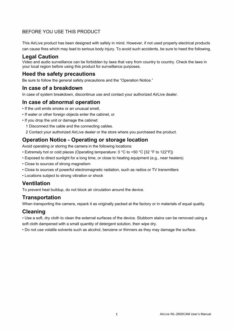
BEFORE YOU USE THIS PRODUCT This AirLive product has been designed with safety in mind. However, if not used properly electrical products can cause fires which may lead to serious body injury. To avoid such accidents, be sure to heed the following.
Legal Caution Video and audio surveillance can be forbidden by laws that vary from country to country. Check the laws in your local region before using this product for surveillance purposes.
Heed the safety precautions Be sure to follow the general safety precautions and the “Operation Notice.”
In case of a breakdown In case of system breakdown, discontinue use and contact your authorized AirLive dealer.
In case of abnormal operation • If the unit emits smoke or an unusual smell, • If water or other foreign objects enter the cabinet, or • If you drop the unit or damage the cabinet:
1 Disconnect the cable and the connecting cables. 2 Contact your authorized AirLive dealer or the store where you purchased the product.
Operation Notice - Operating or storage location Avoid operating or storing the camera in the following locations: • Extremely hot or cold places (Operating temperature: 0 °C to +50 °C [32 °F to 122°F]) • Exposed to direct sunlight for a long time, or close to heating equipment (e.g., near heaters) • Close to sources of strong magnetism • Close to sources of powerful electromagnetic radiation, such as radios or TV transmitters • Locations subject to strong vibration or shock
Ventilation To prevent heat buildup, do not block air circulation around the device.
Transportation When transporting the camera, repack it as originally packed at the factory or in materials of equal quality.
Cleaning • Use a soft, dry cloth to clean the external surfaces of the device. Stubborn stains can be removed using a soft cloth dampened with a small quantity of detergent solution, then wipe dry. • Do not use volatile solvents such as alcohol, benzene or thinners as they may damage the surface.
AirLive WL-2600CAM User’s Manual 2
Table of Contents CHAPTER 1 : MINIMUM SYSTEM REQUIREMENT……………………………………... …..3
CHAPTER 2 : USING IP CAMERA VIA WEB BROWSER……………………………………4 2.1Windows Web Browser.............................................................................................................................. 4 2.2 Mac Web Browser...................................................................................................................................... 7
CHAPTER3: SETTING UP WIRELESS CONFIGURATION…………………………………10 CHAPTER 4: USING IP CAMERA VIA MOBILE PHONE…………………………………...13 4.1 Using IP Camera via iPhone ................................................................................................................... 13 4.2 Mobile Phone Viewing.......................................................................................................................................... 14
CHAPTER 5: CONFIGURATION OF MAIN MENU………………………………………......15 5.1 Live View .................................................................................................................................................. 16 5.2 Setting....................................................................................................................................................... 18 5.3 Client Setting............................................................................................................................................ 19 5.4 Image Setup ............................................................................................................................................. 20 5.5 PT Control ................................................................................................................................................ 21
CHAPTER 6: SETTING-BASIC………………………………………………………………...22 6.1 System ...................................................................................................................................................... 23 6.2 Camera...................................................................................................................................................... 28 6.3 Network..................................................................................................................................................... 34 6.4 Security..................................................................................................................................................... 50
CHAPTER 7: SETTING-ADVANCE…………………………………………………………….53 7.1 PT Control ................................................................................................................................................ 54 7.2 Preset Position......................................................................................................................................... 55 7.3 Patrol......................................................................................................................................................... 56 7.4 FTP Client ................................................................................................................................................. 57 7.5 SMTP......................................................................................................................................................... 64 7.6 HTTP event ............................................................................................................................................... 73 7.7 Alarm Output............................................................................................................................................ 79 7.8 Schedule................................................................................................................................................... 83 7.9 Alarm Input............................................................................................................................................... 85 7.10 Motion Detection.................................................................................................................................... 86 7.11 System Log............................................................................................................................................. 88
AirLive WL-2600CAM User’s Manual 3
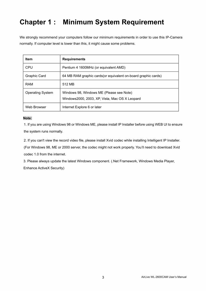
Chapter 1 : Minimum System Requirement We strongly recommend your computers follow our minimum requirements in order to use this IP-Camera
normally. If computer level is lower than this, it might cause some problems.
Item Requirements
CPU Pentium 4 1600MHz (or equivalent AMD)
Graphic Card 64 MB RAM graphic cards(or equivalent on-board graphic cards)
RAM 512 MB
Operating System Windows 98, Windows ME (Please see Note)
Windows2000, 2003, XP, Vista, Mac OS X Leopard
Web Browser Internet Explore 6 or later
Note:
1. If you are using Windows 98 or Windows ME, please install IP Installer before using WEB UI to ensure
the system runs normally.
2. If you can't view the record video file, please install Xvid codec while installing Intelligent IP Installer.
(For Windows 98, ME or 2000 server, the codec might not work properly. You’ll need to download Xvid
codec 1.0 from the internet.
3. Please always update the latest Windows component. (.Net Framework, Windows Media Player,
Enhance ActiveX Security)
AirLive WL-2600CAM User’s Manual
4
Chapter 2 : Using IP Camera via Web Browser
2.1 Windows Web Browser 1. Start your web browser, and enter the IP address or host name of the IP camera in the Location /
Address field of your browser.
Note :
If you only want to view the video without setting page, enter “http://<IP>/index2.htm” as your
web URL.
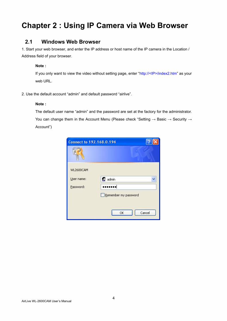
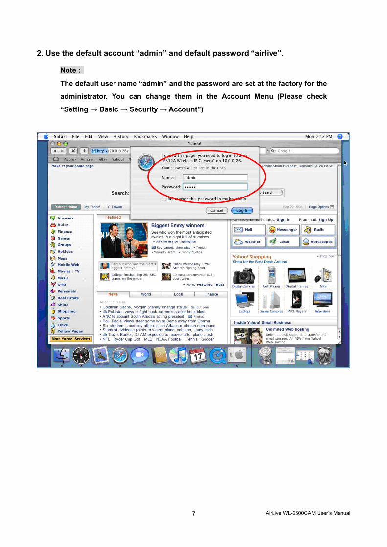
2. Use the default account “admin” and default password “airlive”.
Note :
The default user name “admin” and the password are set at the factory for the administrator.
You can change them in the Account Menu (Please check “Setting → Basic → Security →
Account”)
AirLive WL-2600CAM User’s Manual
5
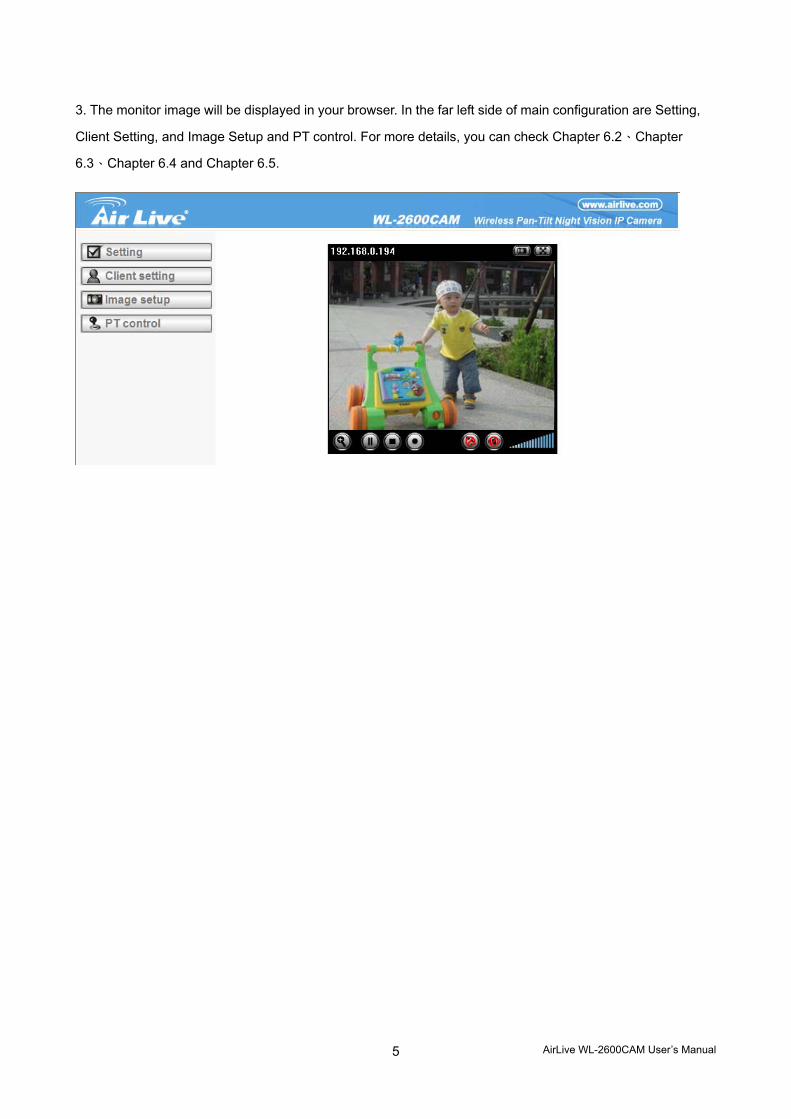
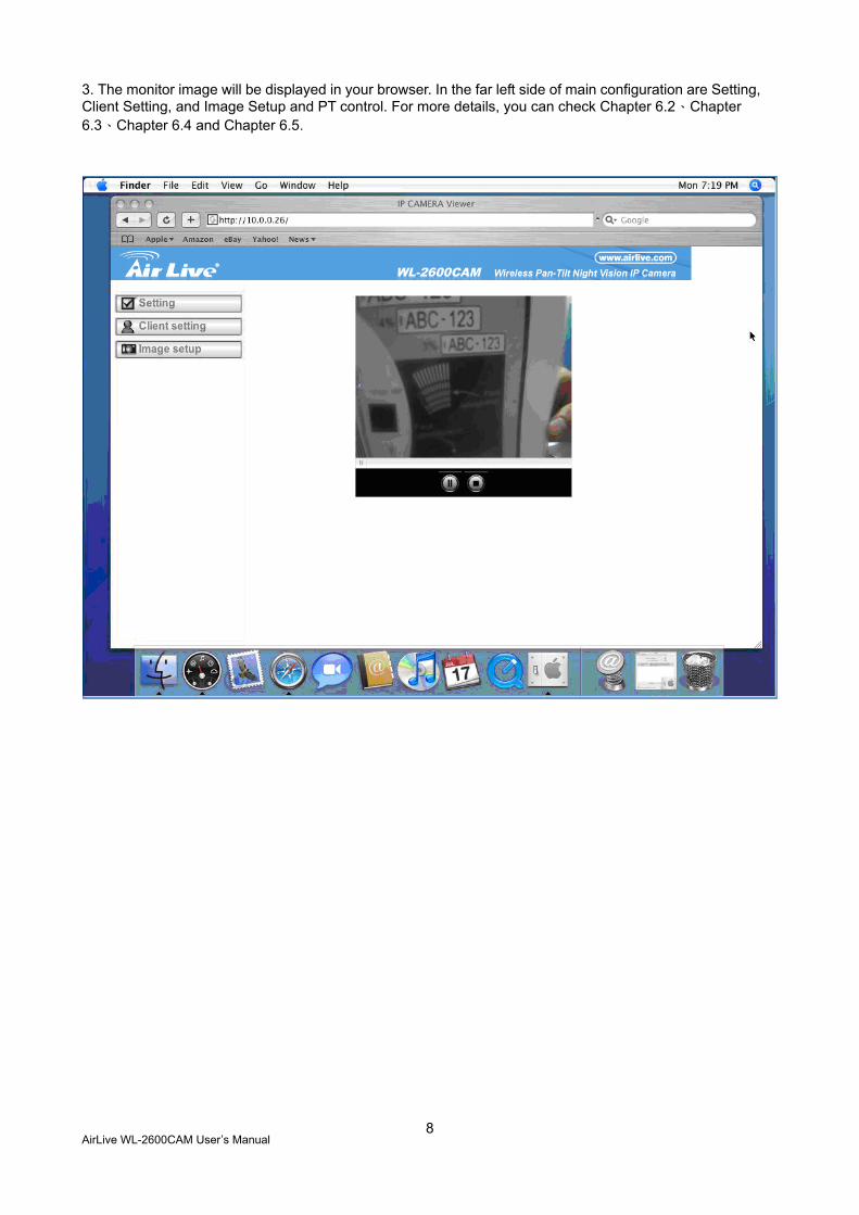
3. The monitor image will be displayed in your browser. In the far left side of main configuration are Setting,
Client Setting, and Image Setup and PT control. For more details, you can check Chapter 6.2、Chapter
6.3、Chapter 6.4 and Chapter 6.5.
AirLive WL-2600CAM User’s Manual
6
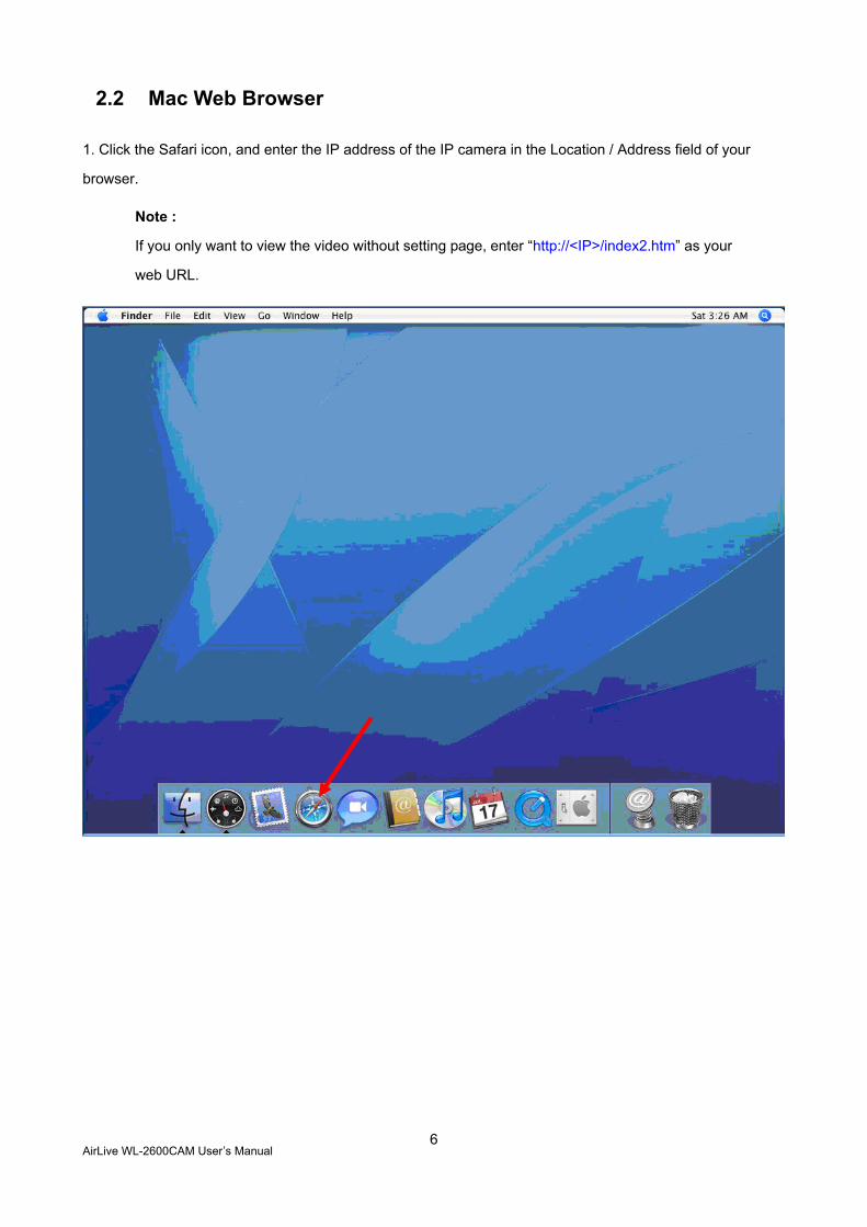
2.2 Mac Web Browser 1. Click the Safari icon, and enter the IP address of the IP camera in the Location / Address field of your
browser.
Note :
If you only want to view the video without setting page, enter “http://<IP>/index2.htm” as your
web URL.
AirLive WL-2600CAM User’s Manual
7
2. Use the default account “admin” and default password “airlive”.
Note :
The default user name “admin” and the password are set at the factory for the
administrator. You can change them in the Account Menu (Please check
“Setting → Basic → Security → Account”)
AirLive WL-2600CAM User’s Manual
8
3. The monitor image will be displayed in your browser. In the far left side of main configuration are Setting, Client Setting, and Image Setup and PT control. For more details, you can check Chapter 6.2、Chapter 6.3、Chapter 6.4 and Chapter 6.5.
AirLive WL-2600CAM User’s Manual
9
Chapter 3 Setting up Wireless Configuration The wireless network has to be set up by using cable network connection. After setting the camera
correctly, the wireless function can work without cable network connection. Please follow the setting
process below step by step:
1. Connect IP Camera with Ethernet connection. (Check chapter 7.3.6 for more details)
2.Go to Setting → Basic → Network → Wireless choose option “On”. You will see the wireless setting
page.
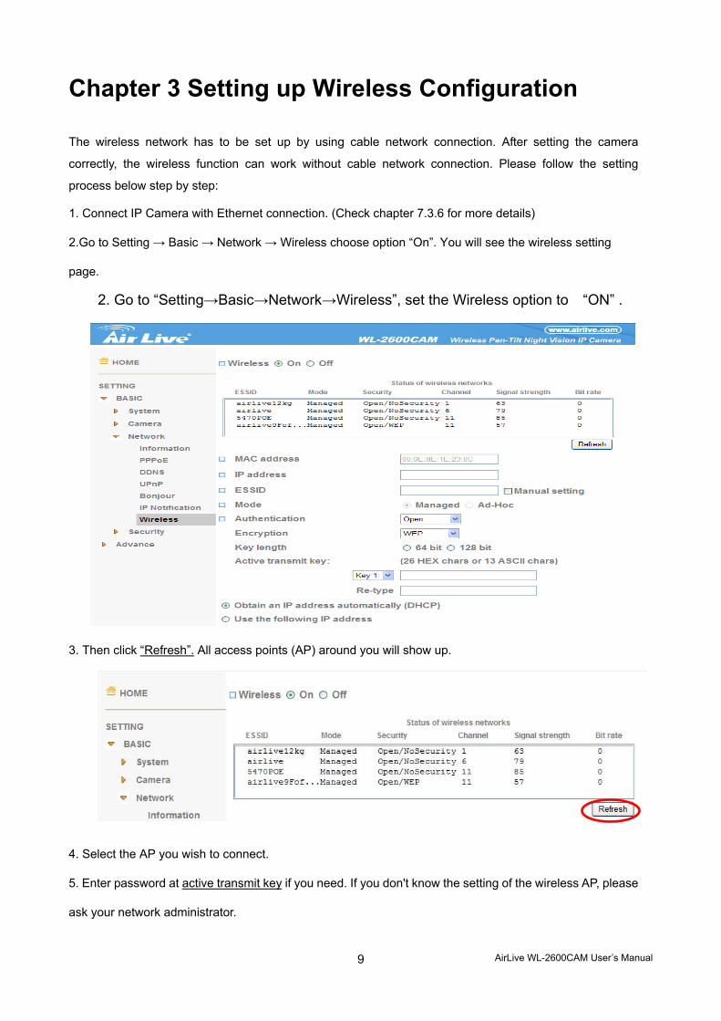
2. Go to “Setting→Basic→Network→Wireless”, set the Wireless option to “ON” .
3. Then click “Refresh”. All access points (AP) around you will show up.
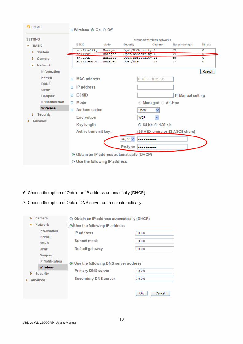
4. Select the AP you wish to connect.
5. Enter password at active transmit key if you need. If you don't know the setting of the wireless AP, please
ask your network administrator.
AirLive WL-2600CAM User’s Manual
10
6. Choose the option of Obtain an IP address automatically (DHCP).
7. Choose the option of Obtain DNS server address automatically.
AirLive WL-2600CAM User’s Manual
11
Use the following IP address: Select this when the fixed IP address is set.
IP address: Enter the IP address of the device. Subnet mask: Enter the subnet mask. Default gateway: Enter the default gateway.
Use the following DNS server address: Select this when you set the fixed address as the IP
address of DNS server.
Primary DNS server: Enter the IP address of the primary DNS server. Secondary DNS server: Enter the IP address of the secondary DNS server, if necessary.
8. Connect to the IP camera with wireless IP address, then you can remove the Ethernet connection.
AirLive WL-2600CAM User’s Manual
12
Chapter 4 : Using IP Camera via Mobile Phone 4.1. Using IP Camera via iPhone
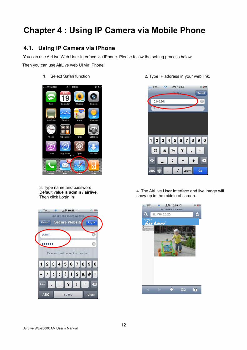
You can use AirLive Web User Interface via iPhone. Please follow the setting process below.
Then you can use AirLive web UI via iPhone.
1. Select Safari function 2. Type IP address in your web link.
3. Type name and password. Default value is admin / airlive. Then click Login In
4. The AirLive User Interface and live image will show up in the middle of screen.
AirLive WL-2600CAM User’s Manual
13
4.2. Mobile Phone Viewing To use IP cameras via mobile phones, please make sure your RTSP is set to “On” (Default is “On”).
To change the settings of IP cameras, Please check “Settings → Basic → Camera→ General.”
4.2.1. 3G Mobile Phone Streaming Viewing
For 3G mobile phone viewing, type “ rtsp://<IP>:<PORT>/video.3gp ” into your 3G Streaming Link.
<IP> is the Public IP address of your IP camera; <PORT> is the RTSP port of your IP camera (Default
value is 554.) Example: rtsp://100.10.10.1:554/video.3gp
Note: You can also use RTSP clients (RealPlayer, VLC, QuickTime Player…etc.) to view
RTSP streaming, just type in “rtsp://<IP>:<PORT>/video.3gp” as the Player URL
4.2.2. 2.5G Mobile Phone WAP Viewing
For 2.5G mobile phone viewing, type “ <IP>/mobile.wml ” into your 2.5G WAP Browser.
<IP> is the Public IP address of your IP camera.
4.2.3. 2.5G Mobile Phone Browser Viewing
For 2.5G mobile phone viewing, type “ <IP>/mobile.htm ” into your 2.5G Web Browser.
<IP> is the Public IP address of your IP camera.
Note: The image is contious snapshots not video. Therefore, you can’t record live image here.
AirLive WL-2600CAM User’s Manual
14
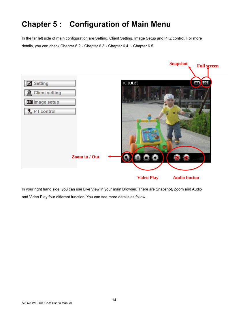
Chapter 5 : Configuration of Main Menu In the far left side of main configuration are Setting, Client Setting, Image Setup and PTZ control. For more
details, you can check Chapter 6.2、Chapter 6.3、Chapter 6.4.、Chapter 6.5.
In your right hand side, you can use Live View in your main Browser. There are Snapshot, Zoom and Audio
and Video Play four different function. You can see more details as follow.
Audio button
Zoom in / Out
Video Play
Snapshot Full screen
AirLive WL-2600CAM User’s Manual
15
5.1 Live View
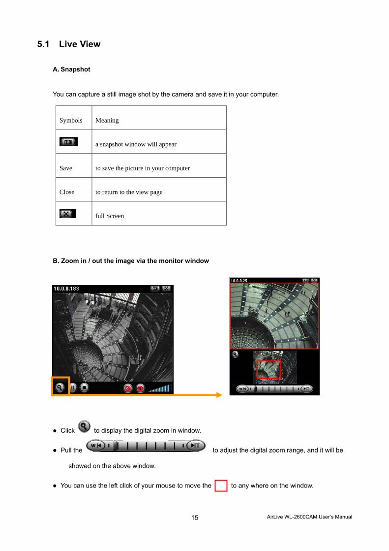
A. Snapshot
You can capture a still image shot by the camera and save it in your computer.
B. Zoom in / out the image via the monitor window
Click to display the digital zoom in window.
Pull the to adjust the digital zoom range, and it will be
showed on the above window.
You can use the left click of your mouse to move the to any where on the window.
Symbols Meaning
a snapshot window will appear
Save to save the picture in your computer
Close to return to the view page
full Screen
AirLive WL-2600CAM User’s Manual
16
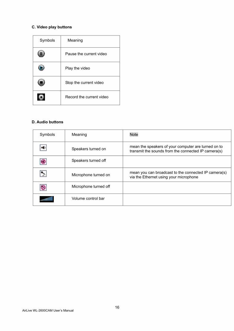
C. Video play buttons
Symbols Meaning
Pause the current video
Play the video
Stop the current video
Record the current video
D. Audio buttons
Symbols Meaning Note
Speakers turned on mean the speakers of your computer are turned on to transmit the sounds from the connected IP camera(s)
Speakers turned off
Microphone turned on mean you can broadcast to the connected IP camera(s) via the Ethernet using your microphone
Microphone turned off
Volume control bar
AirLive WL-2600CAM User’s Manual
17
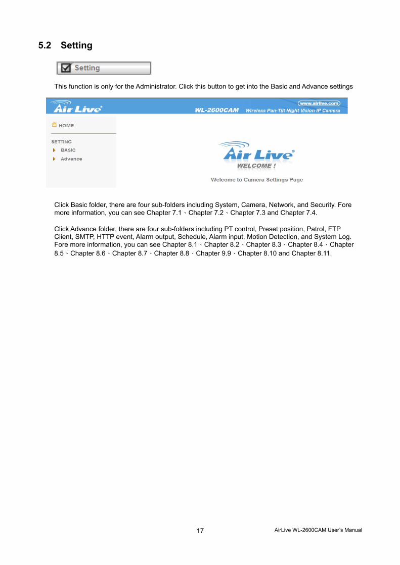
5.2 Setting
This function is only for the Administrator. Click this button to get into the Basic and Advance settings
menu.
Click Basic folder, there are four sub-folders including System, Camera, Network, and Security. Fore more information, you can see Chapter 7.1、Chapter 7.2、Chapter 7.3 and Chapter 7.4. Click Advance folder, there are four sub-folders including PT control, Preset position, Patrol, FTP Client, SMTP, HTTP event, Alarm output, Schedule, Alarm input, Motion Detection, and System Log. Fore more information, you can see Chapter 8.1、Chapter 8.2、Chapter 8.3、Chapter 8.4、Chapter 8.5、Chapter 8.6、Chapter 8.7、Chapter 8.8、Chapter 9.9、Chapter 8.10 and Chapter 8.11.

AirLive WL-2600CAM User’s Manual
18
5.3 Client Setting
This function is only for the client.
Click this button to control Mode, View Size, Protocol, and Video Buffer.
5.3.1 Mode
Click the pull-down box to choose between MPEG4 and MJPEG video compression mode.
MJPEG streaming is unavailable if RTSP mode is “On.”
(Please check Setting → Basic → Camera → General)
Note:MJPEG streaming is unavailable if RTSP mode is On.
5.3.2 View Size
Select the desired display image resolution to 640X480 or 320X240.
5.3.3 Protocol
Select the transferring protocol from TCP, UDP, HTTP and Multicast.
5.3.4 Video Buffer Turn the Video Buffer function ON / OFF. The Video Buffer function makes the streaming more smoothly in unsteady network environment, but might cause a little delay in live viewing.
AirLive WL-2600CAM User’s Manual
19
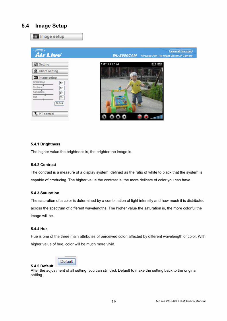
5.4 Image Setup
You can use the tool bar to optimize video Brightness, Contrast, Saturation and Hue.
5.4.1 Brightness
The higher value the brightness is, the brighter the image is.
5.4.2 Contrast
The contrast is a measure of a display system, defined as the ratio of white to black that the system is
capable of producing. The higher value the contrast is, the more delicate of color you can have.
5.4.3 Saturation
The saturation of a color is determined by a combination of light intensity and how much it is distributed
across the spectrum of different wavelengths. The higher value the saturation is, the more colorful the
image will be.
5.4.4 Hue
Hue is one of the three main attributes of perceived color, affected by different wavelength of color. With
higher value of hue, color will be much more vivid.
5.4.5 Default After the adjustment of all setting, you can still click Default to make the setting back to the original setting.
AirLive WL-2600CAM User’s Manual
20
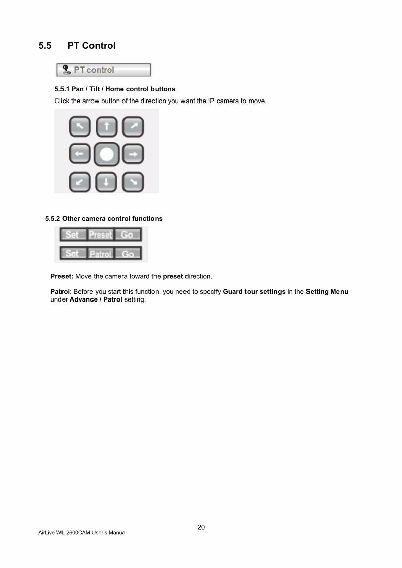
5.5 PT Control
5.5.1 Pan / Tilt / Home control buttons
Click the arrow button of the direction you want the IP camera to move.
5.5.2 Other camera control functions
Preset: Move the camera toward the preset direction. Patrol: Before you start this function, you need to specify Guard tour settings in the Setting Menu under Advance / Patrol setting.
AirLive WL-2600CAM User’s Manual
21
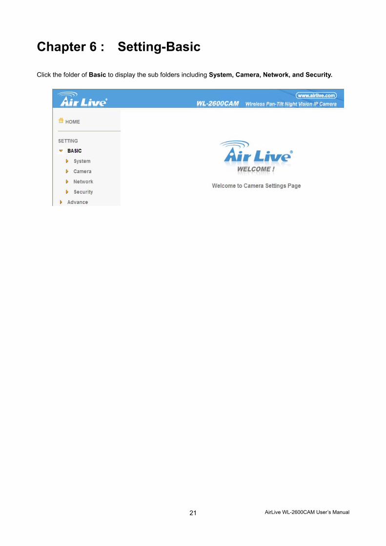
Chapter 6 : Setting-Basic Click the folder of Basic to display the sub folders including System, Camera, Network, and Security.
AirLive WL-2600CAM User’s Manual
22
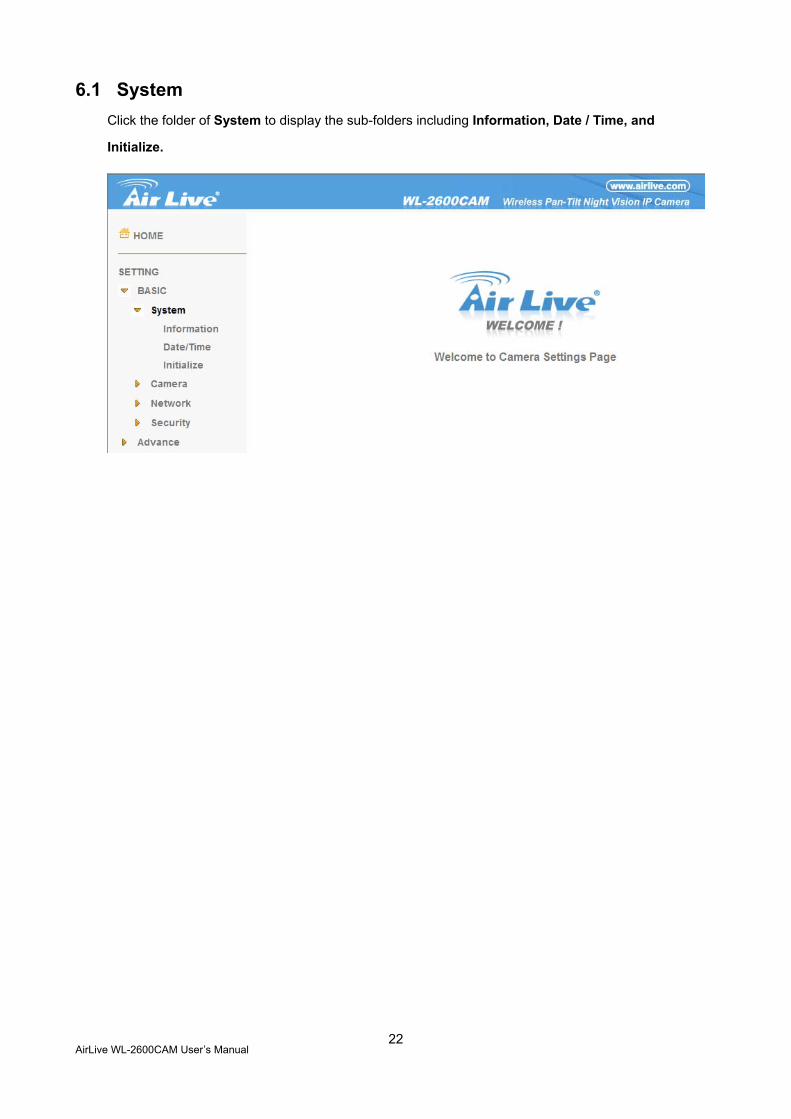
6.1 System Click the folder of System to display the sub-folders including Information, Date / Time, and
Initialize.
AirLive WL-2600CAM User’s Manual
23
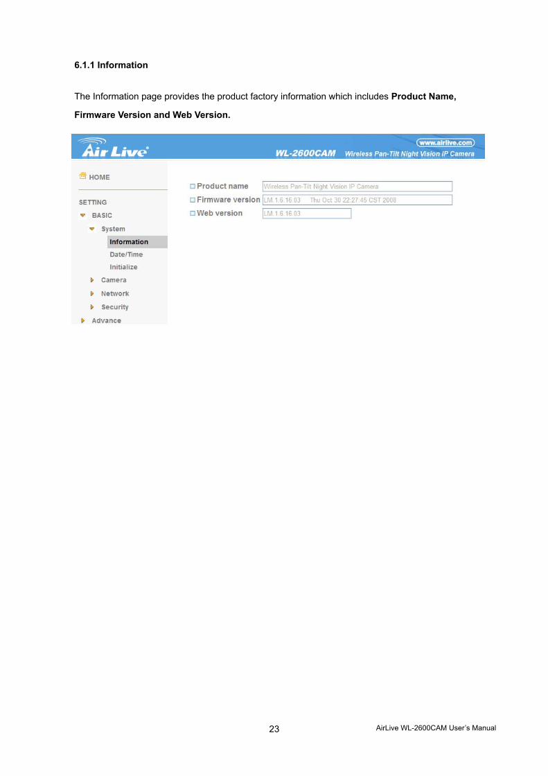
6.1.1 Information
The Information page provides the product factory information which includes Product Name,
Firmware Version and Web Version.
AirLive WL-2600CAM User’s Manual
24
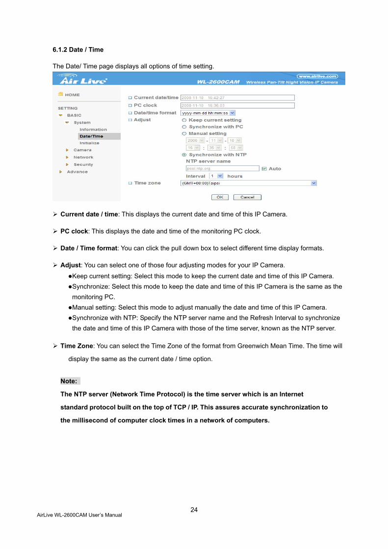
6.1.2 Date / Time
The Date/ Time page displays all options of time setting.
Current date / time: This displays the current date and time of this IP Camera.
PC clock: This displays the date and time of the monitoring PC clock.
Date / Time format: You can click the pull down box to select different time display formats.
Adjust: You can select one of those four adjusting modes for your IP Camera.
Keep current setting: Select this mode to keep the current date and time of this IP Camera. Synchronize: Select this mode to keep the date and time of this IP Camera is the same as the monitoring PC. Manual setting: Select this mode to adjust manually the date and time of this IP Camera. Synchronize with NTP: Specify the NTP server name and the Refresh Interval to synchronize the date and time of this IP Camera with those of the time server, known as the NTP server.
Time Zone: You can select the Time Zone of the format from Greenwich Mean Time. The time will
display the same as the current date / time option.
Note:
The NTP server (Network Time Protocol) is the time server which is an Internet
standard protocol built on the top of TCP / IP. This assures accurate synchronization to
the millisecond of computer clock times in a network of computers.
AirLive WL-2600CAM User’s Manual
25
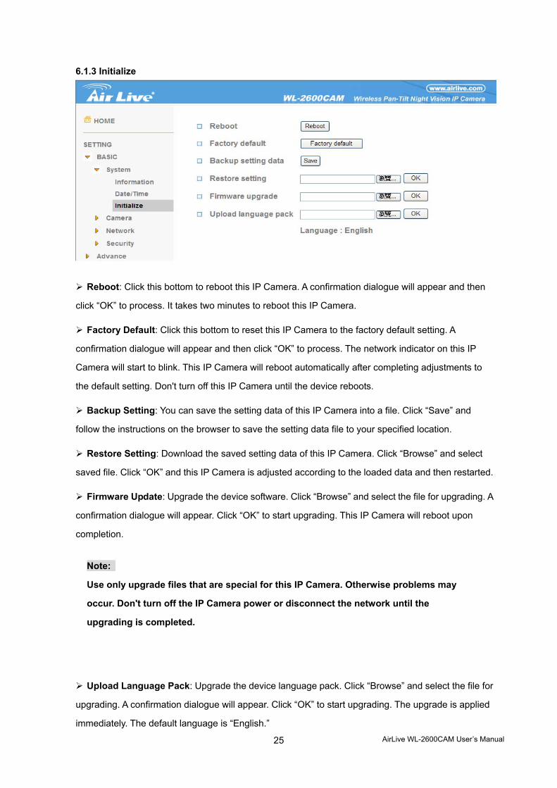
6.1.3 Initialize
Reboot: Click this bottom to reboot this IP Camera. A confirmation dialogue will appear and then
click “OK” to process. It takes two minutes to reboot this IP Camera.
Factory Default: Click this bottom to reset this IP Camera to the factory default setting. A
confirmation dialogue will appear and then click “OK” to process. The network indicator on this IP
Camera will start to blink. This IP Camera will reboot automatically after completing adjustments to
the default setting. Don't turn off this IP Camera until the device reboots.
Backup Setting: You can save the setting data of this IP Camera into a file. Click “Save” and
follow the instructions on the browser to save the setting data file to your specified location.
Restore Setting: Download the saved setting data of this IP Camera. Click “Browse” and select
saved file. Click “OK” and this IP Camera is adjusted according to the loaded data and then restarted.
Firmware Update: Upgrade the device software. Click “Browse” and select the file for upgrading. A
confirmation dialogue will appear. Click “OK” to start upgrading. This IP Camera will reboot upon
completion.
Note:
Use only upgrade files that are special for this IP Camera. Otherwise problems may
occur. Don't turn off the IP Camera power or disconnect the network until the
upgrading is completed.
Upload Language Pack: Upgrade the device language pack. Click “Browse” and select the file for
upgrading. A confirmation dialogue will appear. Click “OK” to start upgrading. The upgrade is applied
immediately. The default language is “English.”
AirLive WL-2600CAM User’s Manual
26
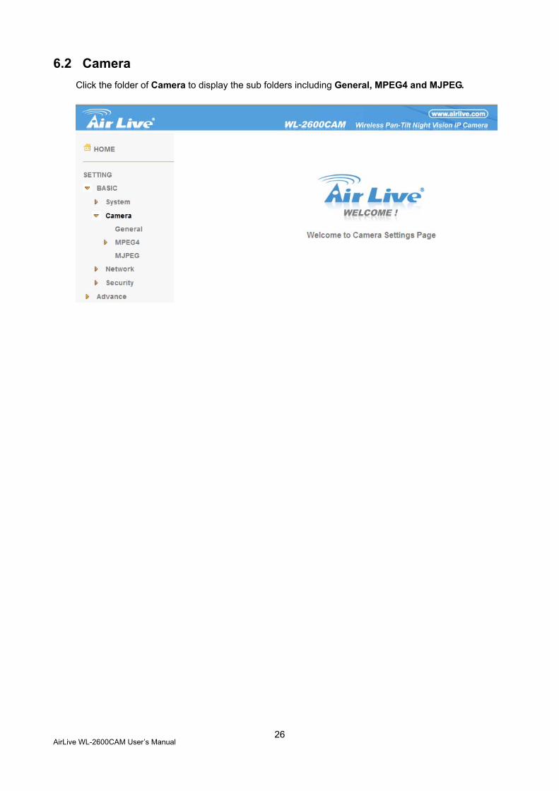
6.2 Camera Click the folder of Camera to display the sub folders including General, MPEG4 and MJPEG.
AirLive WL-2600CAM User’s Manual
27
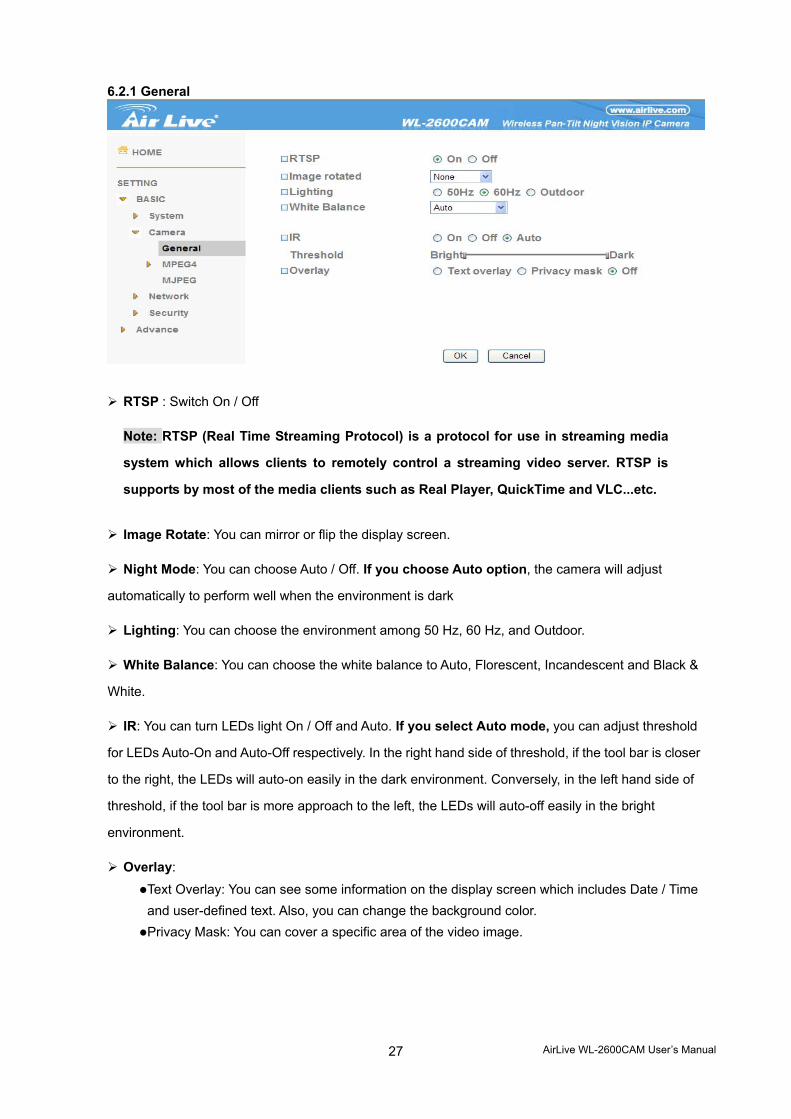
6.2.1 General
RTSP : Switch On / Off
Note: RTSP (Real Time Streaming Protocol) is a protocol for use in streaming media
system which allows clients to remotely control a streaming video server. RTSP is
supports by most of the media clients such as Real Player, QuickTime and VLC...etc.
Image Rotate: You can mirror or flip the display screen.
Night Mode: You can choose Auto / Off. If you choose Auto option, the camera will adjust
automatically to perform well when the environment is dark
Lighting: You can choose the environment among 50 Hz, 60 Hz, and Outdoor.
White Balance: You can choose the white balance to Auto, Florescent, Incandescent and Black &
White.
IR: You can turn LEDs light On / Off and Auto. If you select Auto mode, you can adjust threshold
for LEDs Auto-On and Auto-Off respectively. In the right hand side of threshold, if the tool bar is closer
to the right, the LEDs will auto-on easily in the dark environment. Conversely, in the left hand side of
threshold, if the tool bar is more approach to the left, the LEDs will auto-off easily in the bright
environment.
Overlay:
Text Overlay: You can see some information on the display screen which includes Date / Time and user-defined text. Also, you can change the background color. Privacy Mask: You can cover a specific area of the video image.
AirLive WL-2600CAM User’s Manual
28
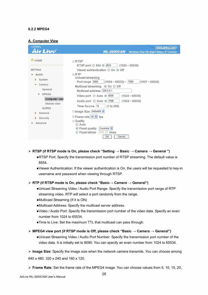
6.2.2 MPEG4
A. Computer View
RTSP (if RTSP mode is On, please check “Setting → Basic → Camera → General ”) RTSP Port: Specify the transmission port number of RTSP streaming. The default value is 8554. Viewer Authentication: If the viewer authentication is On, the users will be requested to key-in username and password when viewing through RTSP.
RTP (if RTSP mode is On, please check “Basic→ Camera → General“) Unicast Streaming Video / Audio Port Range: Specify the transmission port range of RTP streaming video. RTP will select a port randomly from the range. Multicast Streaming (If it is ON) Multicast Address: Specify the multicast server address. Video / Audio Port: Specify the transmission port number of the video data. Specify an even number from 1024 to 65534. Time to Live: Set the maximum TTL that multicast can pass through.
MPEG4 view port (if RTSP mode is Off, please check “Basic → Camera → General”) Unicast Streaming Video / Audio Port Number: Specify the transmission port number of the video data. It is initially set to 8090. You can specify an even number from 1024 to 65534.
Image Size: Specify the image size when the network camera transmits. You can choose among
640 x 480, 320 x 240 and 160 x 120.
Frame Rate: Set the frame rate of the MPEG4 image. You can choose values from 5, 10, 15, 20,
AirLive WL-2600CAM User’s Manual
29
25, and 30 fps. The unit “fps” stands for “frames per second”.
Quality: Auto: The quality and bitratee will be adjusted automatically according to the frame rate. Fixed Quality: You can select the value of quality among Medium, Good, Delicate and Excellent. Fixed Bitrate: Set the bitrate of MPEG4 image transmission for a line. You can select the values from 64, 128, 256, 384, 512, 768, 1024, 1280, 1536, and 2048 kbps.
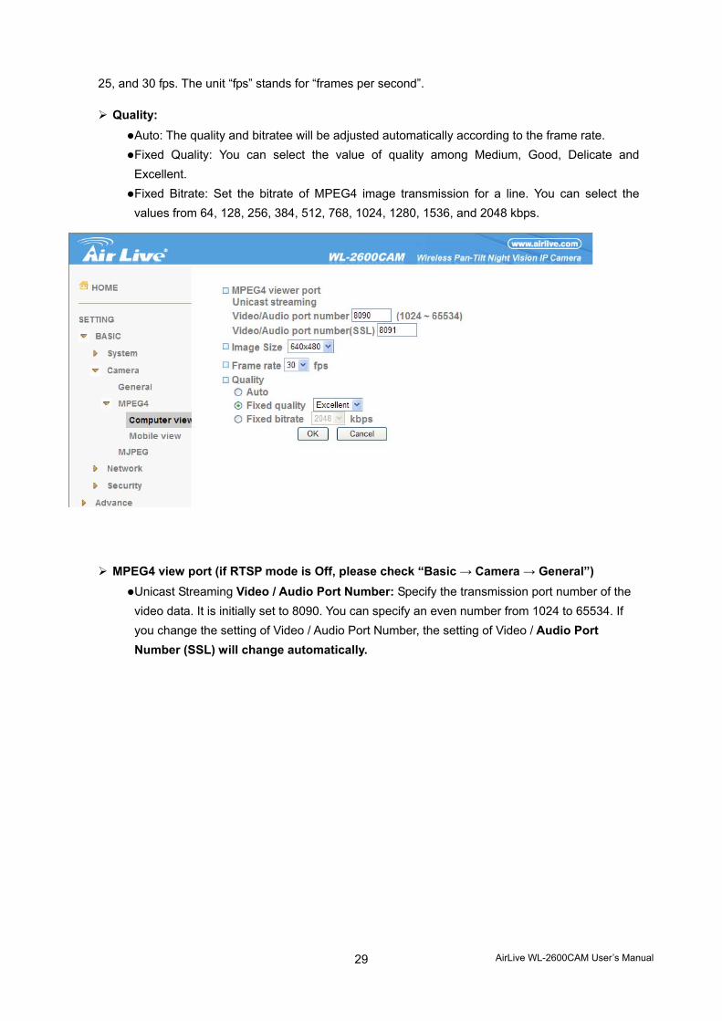
MPEG4 view port (if RTSP mode is Off, please check “Basic → Camera → General”) Unicast Streaming Video / Audio Port Number: Specify the transmission port number of the video data. It is initially set to 8090. You can specify an even number from 1024 to 65534. If you change the setting of Video / Audio Port Number, the setting of Video / Audio Port Number (SSL) will change automatically.
AirLive WL-2600CAM User’s Manual
30
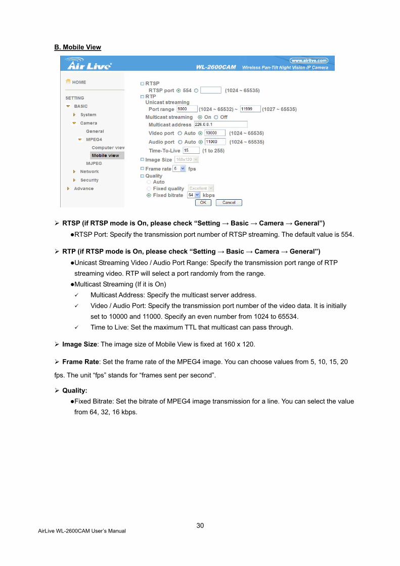
B. Mobile View
RTSP (if RTSP mode is On, please check “Setting → Basic → Camera → General”) RTSP Port: Specify the transmission port number of RTSP streaming. The default value is 554.
RTP (if RTSP mode is On, please check “Setting → Basic → Camera → General”) Unicast Streaming Video / Audio Port Range: Specify the transmission port range of RTP streaming video. RTP will select a port randomly from the range. Multicast Streaming (If it is On)
Multicast Address: Specify the multicast server address. Video / Audio Port: Specify the transmission port number of the video data. It is initially
set to 10000 and 11000. Specify an even number from 1024 to 65534. Time to Live: Set the maximum TTL that multicast can pass through.
Image Size: The image size of Mobile View is fixed at 160 x 120.
Frame Rate: Set the frame rate of the MPEG4 image. You can choose values from 5, 10, 15, 20
fps. The unit “fps” stands for “frames sent per second”.
Quality: Fixed Bitrate: Set the bitrate of MPEG4 image transmission for a line. You can select the value from 64, 32, 16 kbps.
AirLive WL-2600CAM User’s Manual
31
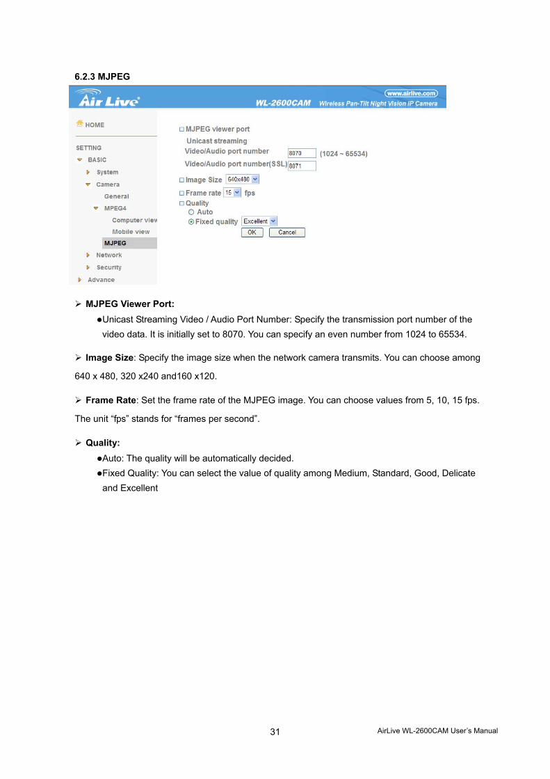
6.2.3 MJPEG
MJPEG Viewer Port: Unicast Streaming Video / Audio Port Number: Specify the transmission port number of the video data. It is initially set to 8070. You can specify an even number from 1024 to 65534.
Image Size: Specify the image size when the network camera transmits. You can choose among
640 x 480, 320 x240 and160 x120.
Frame Rate: Set the frame rate of the MJPEG image. You can choose values from 5, 10, 15 fps.
The unit “fps” stands for “frames per second”.
Quality: Auto: The quality will be automatically decided. Fixed Quality: You can select the value of quality among Medium, Standard, Good, Delicate and Excellent
AirLive WL-2600CAM User’s Manual
32
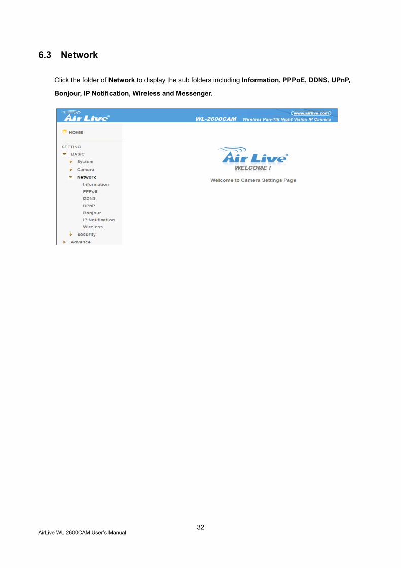
6.3 Network
Click the folder of Network to display the sub folders including Information, PPPoE, DDNS, UPnP,
Bonjour, IP Notification, Wireless and Messenger.
AirLive WL-2600CAM User’s Manual
33
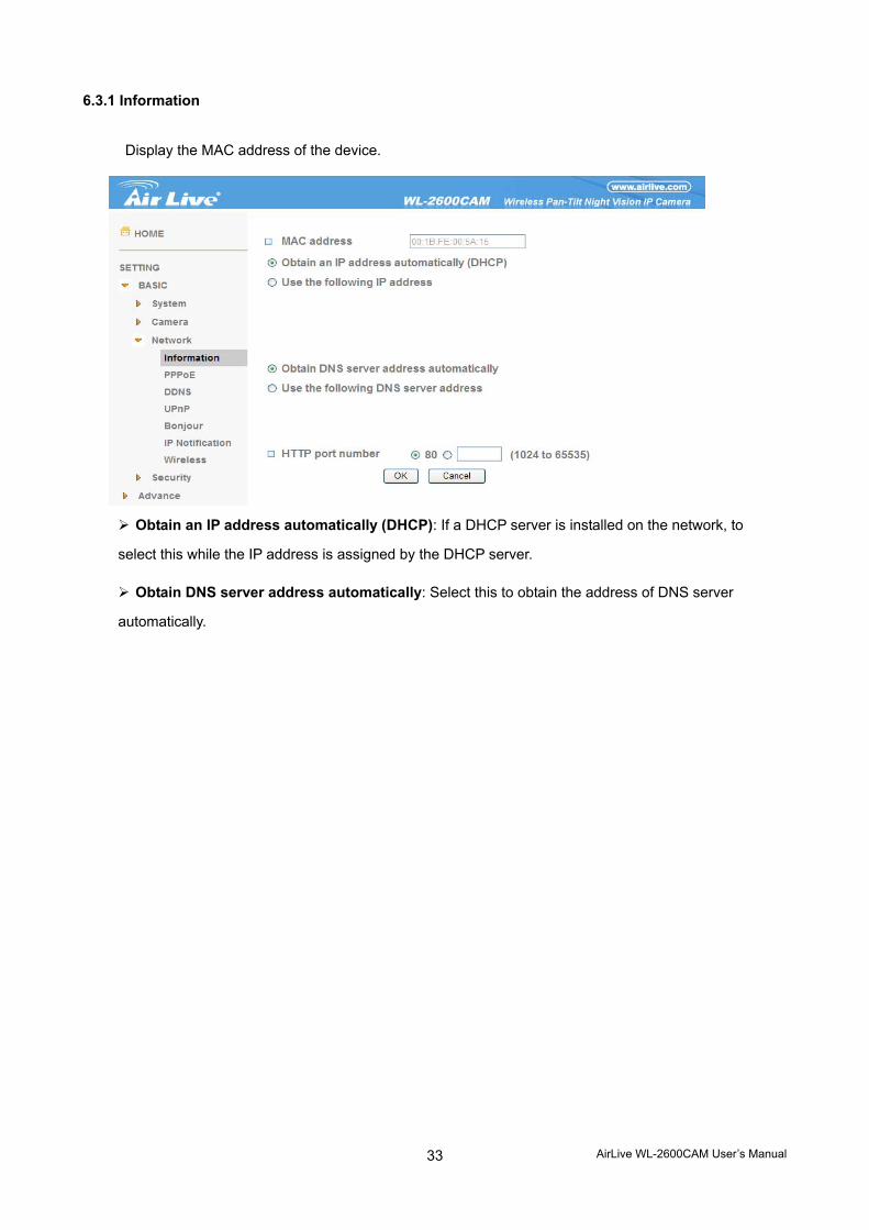
6.3.1 Information
Display the MAC address of the device.
Obtain an IP address automatically (DHCP): If a DHCP server is installed on the network, to
select this while the IP address is assigned by the DHCP server.
Obtain DNS server address automatically: Select this to obtain the address of DNS server
automatically.
AirLive WL-2600CAM User’s Manual
34
Use the following IP address: Select this when the fixed IP address is set.
IP address: Enter the IP address of the device. Subnet mask: Enter the subnet mask. Default gateway: Enter the default gateway.
Use the following DNS server address: Select this when you set the fixed address as the IP
address of DNS server.
Primary DNS server: Enter the IP address of the primary DNS server. Secondary DNS server: Enter the IP address of the secondary DNS server, if necessary.
HTTP port number: Select 80 in general situations. If you want to use a port number other than
80, select the text box and enter a port number between 1024 and 65535.
When you have set the HTTP port number to a number other than 80 on the Network setting page or in the Setup Program, access the device by typing the IP address of the device on the web browser as follows: Example: when HTTP port number is set to 2000 http://192.168.1.100:2000/
Note: The IP Camera needs to be rebooted after it finishes changing the network setting
completely.
Note: If you connect the IP Camera with your computer directly, the default network domain of
camera is 192.168.1.x
AirLive WL-2600CAM User’s Manual
35
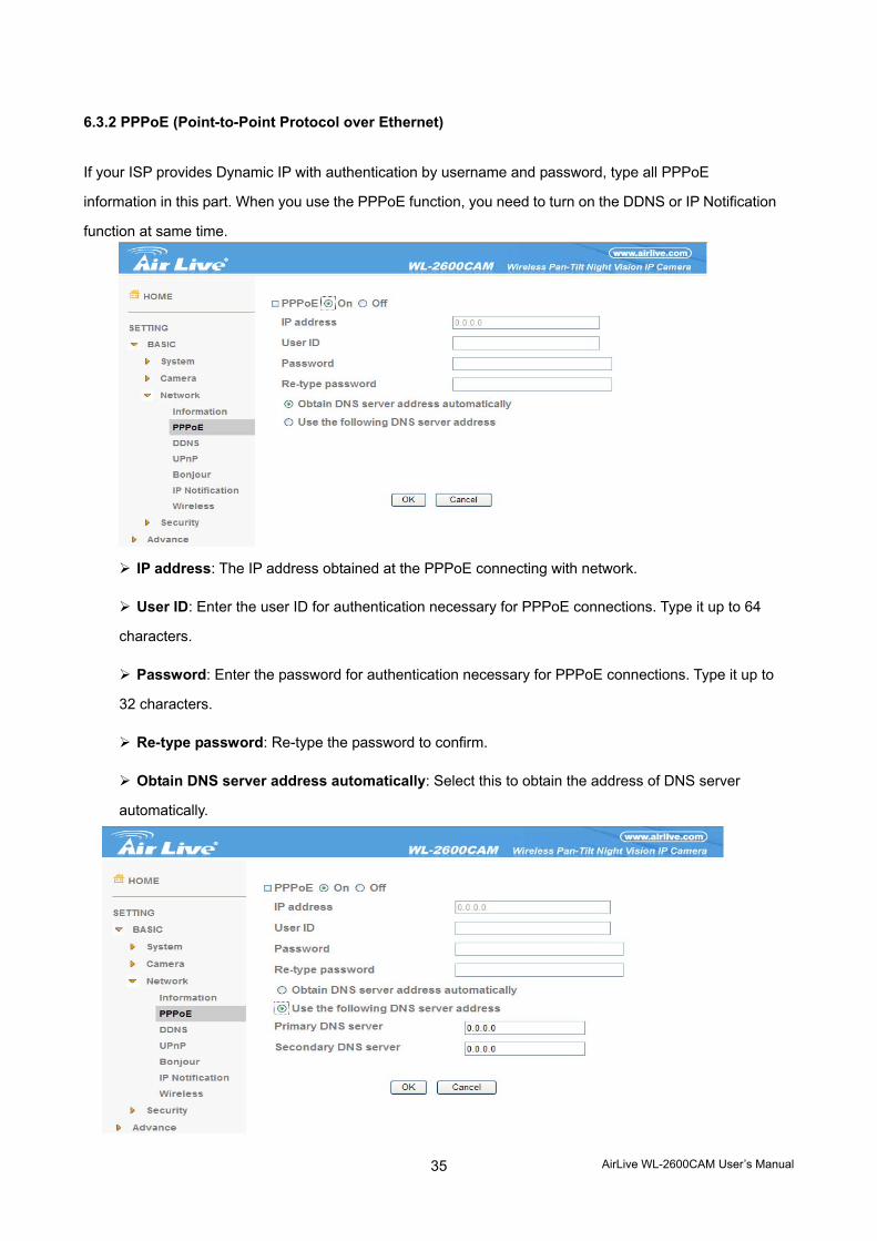
6.3.2 PPPoE (Point-to-Point Protocol over Ethernet)
If your ISP provides Dynamic IP with authentication by username and password, type all PPPoE
information in this part. When you use the PPPoE function, you need to turn on the DDNS or IP Notification
function at same time.
IP address: The IP address obtained at the PPPoE connecting with network.
User ID: Enter the user ID for authentication necessary for PPPoE connections. Type it up to 64
characters.
Password: Enter the password for authentication necessary for PPPoE connections. Type it up to
32 characters.
Re-type password: Re-type the password to confirm.
Obtain DNS server address automatically: Select this to obtain the address of DNS server
automatically.
AirLive WL-2600CAM User’s Manual
36
Use the following DNS server address: Select this when you set the fixed address as the IP
address of DNS server.
Primary DNS server: Enter the IP address of the primary DNS server. Secondary DNS server: Enter the IP address of the secondary DNS server.
Note :
1. PPPoE (Point-to-Point Protocol over Ethernet): PPPoE is a network protocol for
encapsulating Point-to-Point Protocol frames insider Ethernet frames. PPPoE
connection is used mainly with ADSL service where individual users connect to the
ADSL transceiver (modem) over Ethernet work. It also widely used in XDSL (digital
affiliate line such as ADSL, VDSL or SDSL)
2. The IP Camera needs to be rebooted after it finishes changing the network
completely.
3. The IP Camera with Intelligent IP Installer can’t be founded after turning on the
PPPoE and reboot.
AirLive WL-2600CAM User’s Manual
37
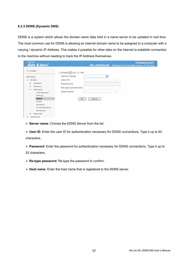
6.3.3 DDNS (Dynamic DNS)
DDNS is a system which allows the domain name data held in a name server to be updated in real time.
The most common use for DDNS is allowing an internet domain name to be assigned to a computer with a
varying / dynamic IP Address. This makes it possible for other sites on the internet to establish connection
to the machine without needing to track the IP Address themselves.
Server name: Choose the DDNS Server from the list.
User ID: Enter the user ID for authentication necessary for DDNS connections. Type it up to 64
characters.
Password: Enter the password for authentication necessary for DDNS connections. Type it up to
32 characters.
Re-type password: Re-type the password to confirm.
Host name: Enter the host name that is registered to the DDNS server.
AirLive WL-2600CAM User’s Manual
38
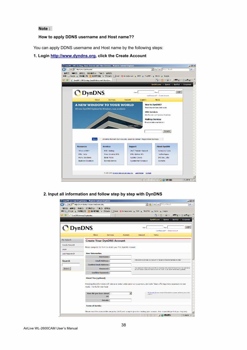
Note :
How to apply DDNS username and Host name??
You can apply DDNS username and Host name by the following steps:
1. Login http://www.dyndns.org, click the Create Account
2. Input all information and follow step by step with DynDNS
.
AirLive WL-2600CAM User’s Manual
39
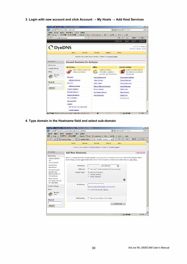
3. Login with new account and click Account → My Hosts → Add Host Services
4. Type domain in the Hostname field and select sub-domain
AirLive WL-2600CAM User’s Manual
40
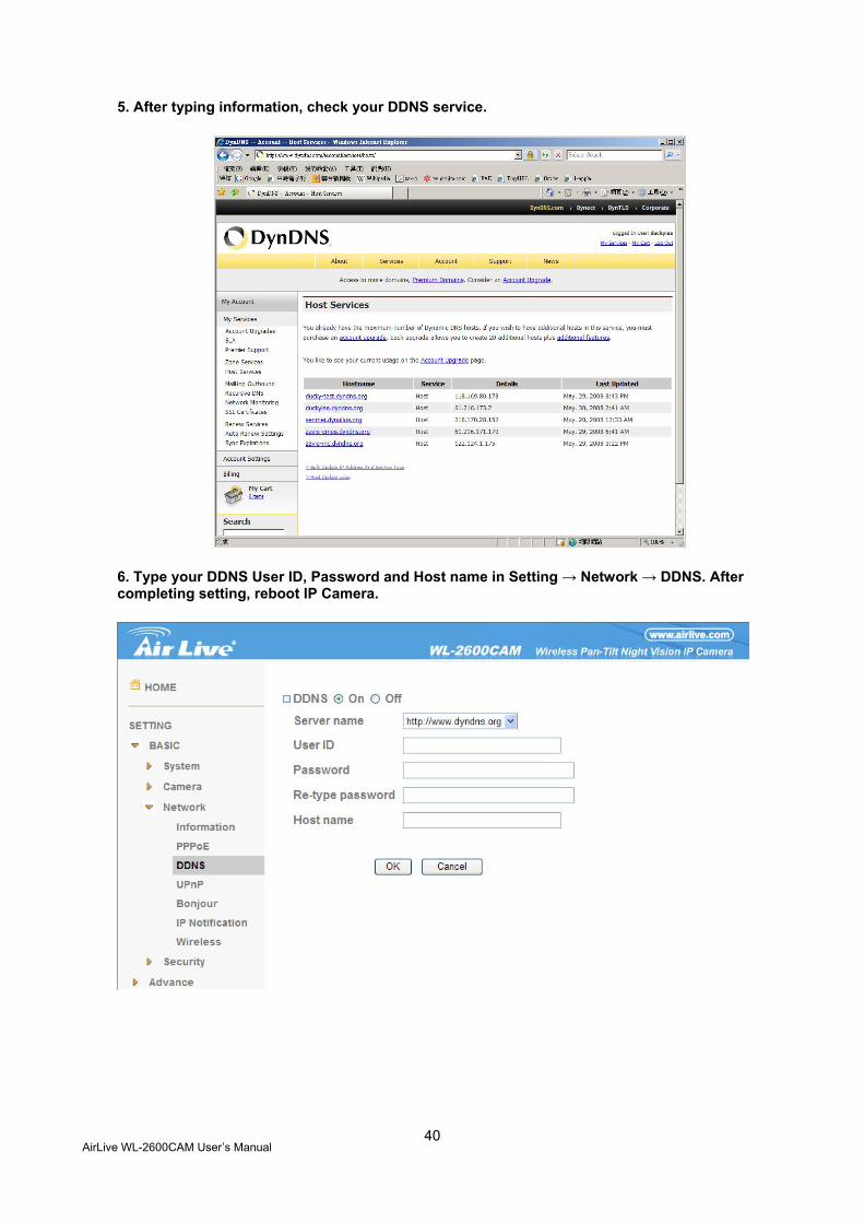
5. After typing information, check your DDNS service.
6. Type your DDNS User ID, Password and Host name in Setting → Network → DDNS. After completing setting, reboot IP Camera.
AirLive WL-2600CAM User’s Manual
41
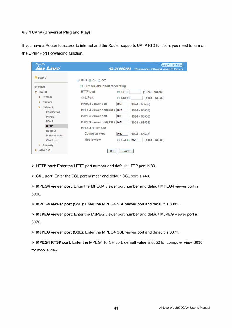
6.3.4 UPnP (Universal Plug and Play)
If you have a Router to access to internet and the Router supports UPnP IGD function, you need to turn on
the UPnP Port Forwarding function.
HTTP port: Enter the HTTP port number and default HTTP port is 80.
SSL port: Enter the SSL port number and default SSL port is 443.
MPEG4 viewer port: Enter the MPEG4 viewer port number and default MPEG4 viewer port is
8090.
MPEG4 viewer port (SSL): Enter the MPEG4 SSL viewer port and default is 8091.
MJPEG viewer port: Enter the MJPEG viewer port number and default MJPEG viewer port is
8070.
MJPEG viewer port (SSL): Enter the MPEG4 SSL viewer port and default is 8071.
MPEG4 RTSP port: Enter the MPEG4 RTSP port, default value is 8050 for computer view, 8030
for mobile view.

AirLive WL-2600CAM User’s Manual
42
Note :
UPnP (Universal Plug and Play): UPnP is a set of computer network protocol. It allows devices
to connect seamlessly and simplify the implementation of networks in the home and corporate
environments. The device supports UPnP which is enabled by default. The device will be
automatically detected and a new icon will be added to “My Network Place” if it also enables
on your computer. It provides Port Forwarding for opening a port in a router or firewall in a
private network in order to let a party from the outside world contact a inside user.
AirLive WL-2600CAM User’s Manual
43
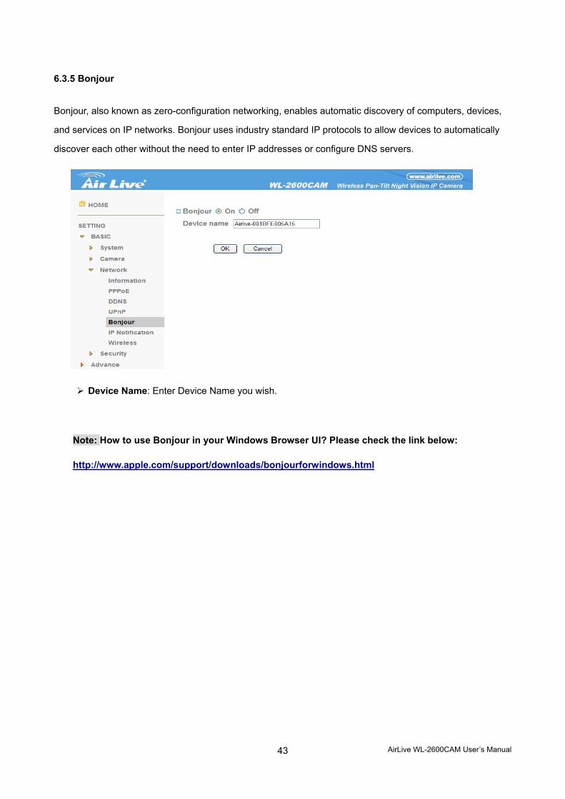
6.3.5 Bonjour
Bonjour, also known as zero-configuration networking, enables automatic discovery of computers, devices,
and services on IP networks. Bonjour uses industry standard IP protocols to allow devices to automatically
discover each other without the need to enter IP addresses or configure DNS servers.
Device Name: Enter Device Name you wish.
Note: How to use Bonjour in your Windows Browser UI? Please check the link below:
http://www.apple.com/support/downloads/bonjourforwindows.html
AirLive WL-2600CAM User’s Manual
44
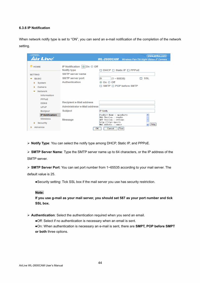
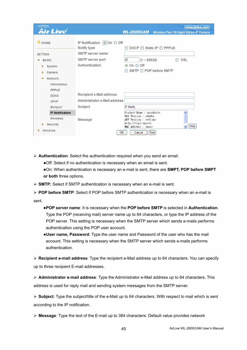
6.3.6 IP Notification
When network notify type is set to “ON”, you can send an e-mail notification of the completion of the network
setting.
Notify Type: You can select the notify type among DHCP, Static IP, and PPPoE.
SMTP Server Name: Type the SMTP server name up to 64 characters, or the IP address of the
SMTP server.
SMTP Server Port: You can set port number from 1~65535 according to your mail server. The
default value is 25.
Security setting: Tick SSL box if the mail server you use has security restriction. Note: If you use g-mail as your mail server, you should set 587 as your port number and tick SSL box.
Authentication: Select the authentication required when you send an email.
Off: Select if no authentication is necessary when an email is sent. On: When authentication is necessary an e-mail is sent, there are SMPT, POP before SMPT
or both three options.
AirLive WL-2600CAM User’s Manual
45
Authentication: Select the authentication required when you send an email.
Off: Select if no authentication is necessary when an email is sent. On: When authentication is necessary an e-mail is sent, there are SMPT, POP before SMPT
or both three options.
SMTP: Select if SMTP authentication is necessary when an e-mail is sent.
POP before SMTP: Select if POP before SMTP authentication is necessary when an e-mail is
sent.
POP server name: It is necessary when the POP before SMTP is selected in Authentication. Type the POP (receiving mail) server name up to 64 characters, or type the IP address of the POP server. This setting is necessary when the SMTP server which sends e-mails performs authentication using the POP user account. User name, Password: Type the user name and Password of the user who has the mail account. This setting is necessary when the SMTP server which sends e-mails performs authentication.
Recipient e-mail address: Type the recipient e-Mail address up to 64 characters. You can specify
up to three recipient E-mail addresses.
Administrator e-mail address: Type the Administrator e-Mail address up to 64 characters. This
address is used for reply mail and sending system messages from the SMTP server.
Subject: Type the subject/title of the e-Mail up to 64 characters. With respect to mail which is sent
according to the IP notification.
Message: Type the text of the E-mail up to 384 characters. Default value provides network
AirLive WL-2600CAM User’s Manual
46
information including IP, Port, MAC, Model, Firmware Version and Web Version.
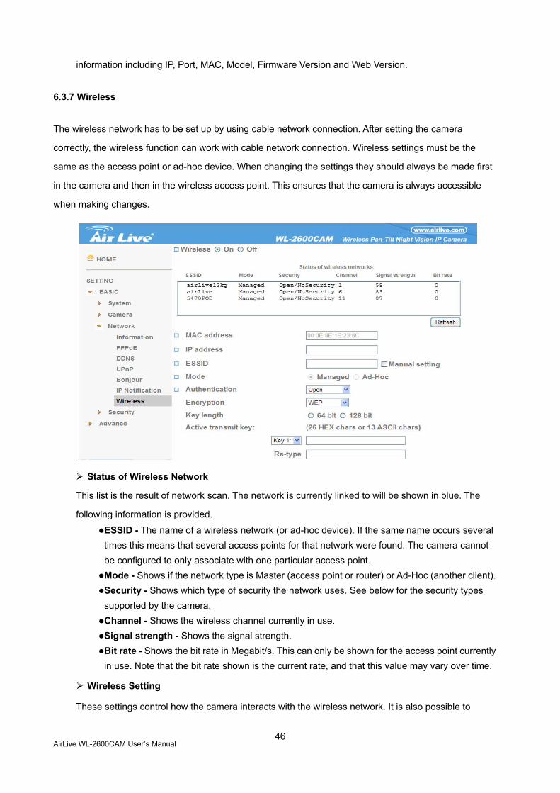
6.3.7 Wireless
The wireless network has to be set up by using cable network connection. After setting the camera
correctly, the wireless function can work with cable network connection. Wireless settings must be the
same as the access point or ad-hoc device. When changing the settings they should always be made first
in the camera and then in the wireless access point. This ensures that the camera is always accessible
when making changes.
Status of Wireless Network
This list is the result of network scan. The network is currently linked to will be shown in blue. The
following information is provided.
ESSID - The name of a wireless network (or ad-hoc device). If the same name occurs several times this means that several access points for that network were found. The camera cannot be configured to only associate with one particular access point. Mode - Shows if the network type is Master (access point or router) or Ad-Hoc (another client). Security - Shows which type of security the network uses. See below for the security types supported by the camera. Channel - Shows the wireless channel currently in use. Signal strength - Shows the signal strength. Bit rate - Shows the bit rate in Megabit/s. This can only be shown for the access point currently in use. Note that the bit rate shown is the current rate, and that this value may vary over time.
Wireless Setting
These settings control how the camera interacts with the wireless network. It is also possible to
AirLive WL-2600CAM User’s Manual
47
enable wireless encryption apart from identifying the wireless network.
IP Address – This displays blank, 0.0.0.0 or IP Address. When it is blank, the camera doesn’t establish physical link with access point yet. The 0.0.0.0 means that physical link was established but trying to get IP address. When it displays IP address, then user can use wireless network. ESSID (ESSID is sometimes written as SSID.) - This is the name of the wireless network the camera is configured for. The field accepts up to 32 alphanumeric characters. The name must be exactly the same as that used in the wireless access point or the connection will not be established. Leaving this field blank means the camera will attempt to access the nearest open network.
Mode - Setting this to Managed means the camera will attempt to access the nearest open access point. The Ad-hoc option allows the camera to connect to other wireless devices clients.
Note :
1. WPA-/WPA2-PSK (Wi-Fi Protected Access - Pre-Shared Key) the camera uses a
pre-shared key (PSK) to initiate WPA security. The pre-shared key is entered on the
access point and on each device on the wireless network. The key can be entered
either as Manual hex, as 64 hexadecimal (0-9, A-F) characters, or as a Passphrase,
using 8 to 63 ASCII characters. The access point keeps out unauthorized users by
requiring the key to communicate.
2. WEP (Wired Equivalent Protection) the original security standard used in wireless
networks that provides a minimal level of security that can deter minor trespasses.
The administrator can select the key length among 64 or 128 bits. 64bits is the default
setting.
AirLive WL-2600CAM User’s Manual
48
6.4 Security
Click the folder of Security to display the sub folders including Account and HTTPS.
AirLive WL-2600CAM User’s Manual
49
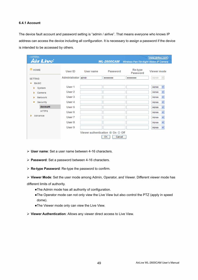
6.4.1 Account
The device fault account and password setting is “admin / airlive”. That means everyone who knows IP
address can access the device including all configuration. It is necessary to assign a password if the device
is intended to be accessed by others.
User name: Set a user name between 4-16 characters.
Password: Set a password between 4-16 characters.
Re-type Password: Re-type the password to confirm.
Viewer Mode: Set the user mode among Admin, Operator, and Viewer. Different viewer mode has
different limits of authority.
The Admin mode has all authority of configuration. The Operator mode can not only view the Live View but also control the PTZ (apply in speed dome). The Viewer mode only can view the Live View.
Viewer Authentication: Allows any viewer direct access to Live View.
AirLive WL-2600CAM User’s Manual
50
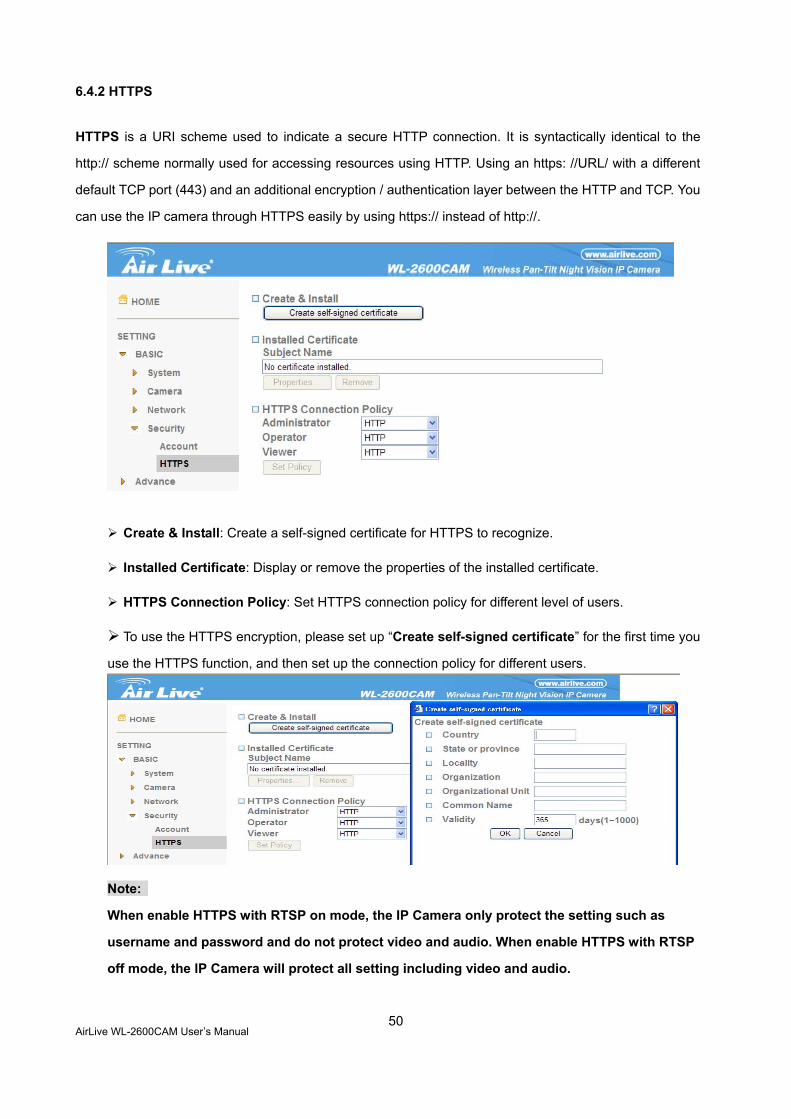
6.4.2 HTTPS
HTTPS is a URI scheme used to indicate a secure HTTP connection. It is syntactically identical to the
http:// scheme normally used for accessing resources using HTTP. Using an https: //URL/ with a different
default TCP port (443) and an additional encryption / authentication layer between the HTTP and TCP. You
can use the IP camera through HTTPS easily by using https:// instead of http://.
Create & Install: Create a self-signed certificate for HTTPS to recognize.
Installed Certificate: Display or remove the properties of the installed certificate.
HTTPS Connection Policy: Set HTTPS connection policy for different level of users.
To use the HTTPS encryption, please set up “Create self-signed certificate” for the first time you
use the HTTPS function, and then set up the connection policy for different users.
Note:
When enable HTTPS with RTSP on mode, the IP Camera only protect the setting such as
username and password and do not protect video and audio. When enable HTTPS with RTSP
off mode, the IP Camera will protect all setting including video and audio.
AirLive WL-2600CAM User’s Manual
51
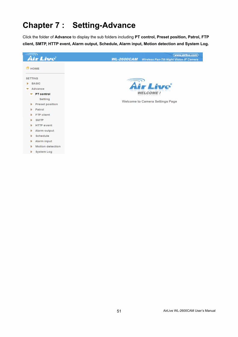
Chapter 7 : Setting-Advance Click the folder of Advance to display the sub folders including PT control, Preset position, Patrol, FTP client, SMTP, HTTP event, Alarm output, Schedule, Alarm input, Motion detection and System Log.
AirLive WL-2600CAM User’s Manual
52
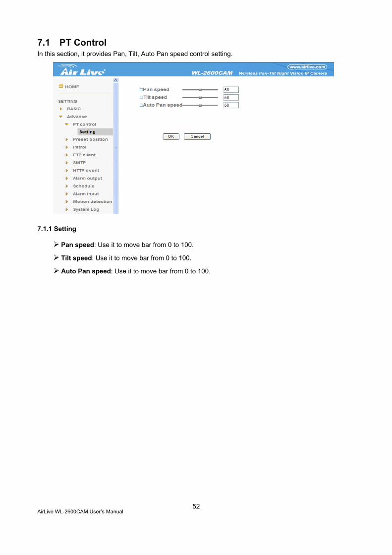
7.1 PT Control In this section, it provides Pan, Tilt, Auto Pan speed control setting.
7.1.1 Setting
Pan speed: Use it to move bar from 0 to 100.
Tilt speed: Use it to move bar from 0 to 100.
Auto Pan speed: Use it to move bar from 0 to 100.
AirLive WL-2600CAM User’s Manual
53
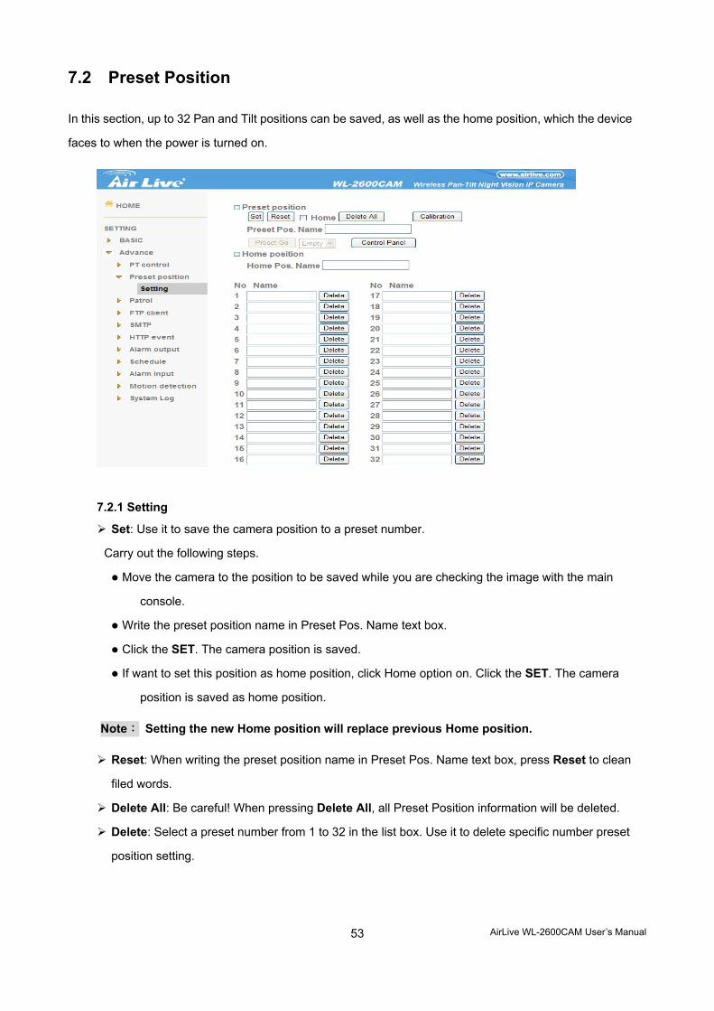
7.2 Preset Position
In this section, up to 32 Pan and Tilt positions can be saved, as well as the home position, which the device
faces to when the power is turned on.
7.2.1 Setting
Set: Use it to save the camera position to a preset number.
Carry out the following steps.
Move the camera to the position to be saved while you are checking the image with the main
console.
Write the preset position name in Preset Pos. Name text box.
Click the SET. The camera position is saved.
If want to set this position as home position, click Home option on. Click the SET. The camera
position is saved as home position.
Note: Setting the new Home position will replace previous Home position.
Reset: When writing the preset position name in Preset Pos. Name text box, press Reset to clean
filed words.
Delete All: Be careful! When pressing Delete All, all Preset Position information will be deleted.
Delete: Select a preset number from 1 to 32 in the list box. Use it to delete specific number preset
position setting.
AirLive WL-2600CAM User’s Manual
54
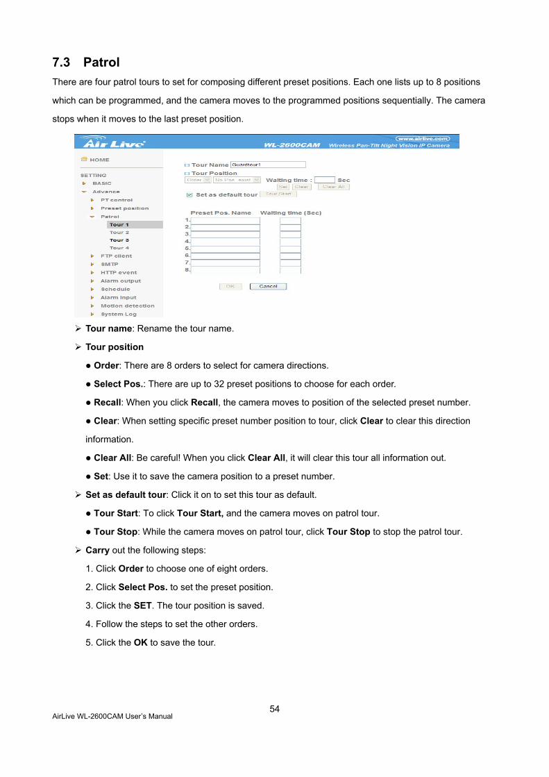
7.3 Patrol There are four patrol tours to set for composing different preset positions. Each one lists up to 8 positions
which can be programmed, and the camera moves to the programmed positions sequentially. The camera
stops when it moves to the last preset position.
Tour name: Rename the tour name.
Tour position
Order: There are 8 orders to select for camera directions.
Select Pos.: There are up to 32 preset positions to choose for each order.
Recall: When you click Recall, the camera moves to position of the selected preset number.
Clear: When setting specific preset number position to tour, click Clear to clear this direction
information.
Clear All: Be careful! When you click Clear All, it will clear this tour all information out.
Set: Use it to save the camera position to a preset number.
Set as default tour: Click it on to set this tour as default.
Tour Start: To click Tour Start, and the camera moves on patrol tour.
Tour Stop: While the camera moves on patrol tour, click Tour Stop to stop the patrol tour.
Carry out the following steps:
1. Click Order to choose one of eight orders.
2. Click Select Pos. to set the preset position.
3. Click the SET. The tour position is saved.
4. Follow the steps to set the other orders.
5. Click the OK to save the tour.
AirLive WL-2600CAM User’s Manual
55
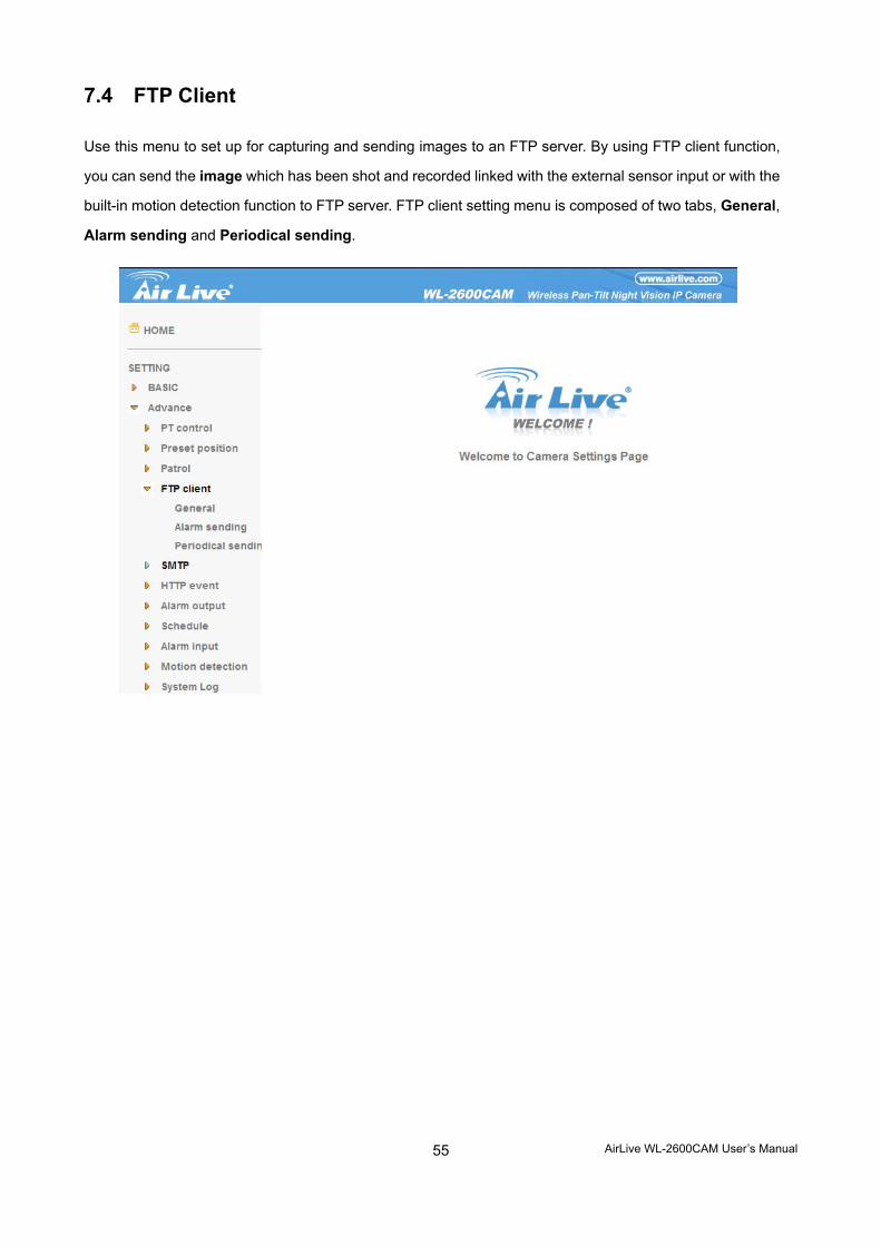
7.4 FTP Client
Use this menu to set up for capturing and sending images to an FTP server. By using FTP client function,
you can send the image which has been shot and recorded linked with the external sensor input or with the
built-in motion detection function to FTP server. FTP client setting menu is composed of two tabs, General,
Alarm sending and Periodical sending.
AirLive WL-2600CAM User’s Manual
56
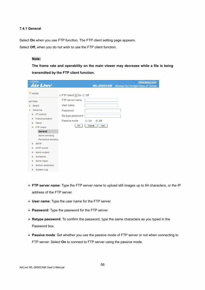
7.4.1 General
Select On when you use FTP function. The FTP client setting page appears.
Select Off, when you do not wish to use the FTP client function.
Note:
The frame rate and operability on the main viewer may decrease while a file is being
transmitted by the FTP client function.
FTP server name: Type the FTP server name to upload still images up to 64 characters, or the IP
address of the FTP server.
User name: Type the user name for the FTP server.
Password: Type the password for the FTP server.
Retype password: To confirm the password, type the same characters as you typed in the
Password box.
Passive mode: Set whether you use the passive mode of FTP server or not when connecting to
FTP server. Select On to connect to FTP server using the passive mode.
AirLive WL-2600CAM User’s Manual
57
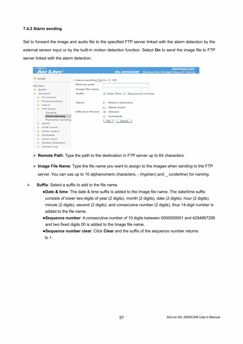
7.4.2 Alarm sending
Set to forward the image and audio file to the specified FTP server linked with the alarm detection by the
external sensor input or by the built-in motion detection function. Select On to send the image file to FTP
server linked with the alarm detection.
Remote Path: Type the path to the destination in FTP server up to 64 characters.
Image File Name: Type the file name you want to assign to the images when sending to the FTP
server. You can use up to 10 alphanumeric characters, - (hyphen) and _ (underline) for naming.
Suffix: Select a suffix to add to the file name
Date & time: The date & time suffix is added to the Image file name. The date/time suffix consists of lower two-digits of year (2 digits), month (2 digits), date (2 digits), hour (2 digits), minute (2 digits), second (2 digits), and consecutive number (2 digits), thus 14-digit number is added to the file name. Sequence number: A consecutive number of 10 digits between 0000000001 and 4294967295 and two fixed digits 00 is added to the Image file name. Sequence number clear: Click Clear and the suffix of the sequence number returns to 1.
AirLive WL-2600CAM User’s Manual
58
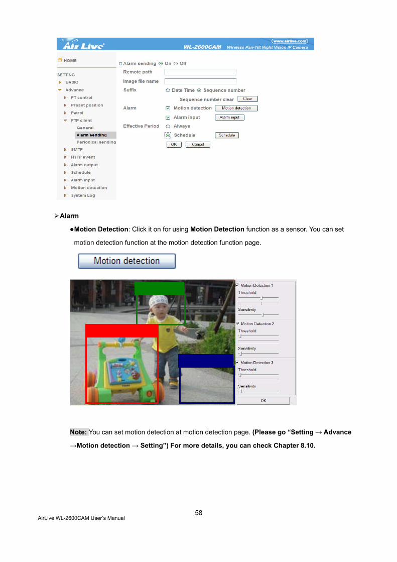
Alarm
Motion Detection: Click it on for using Motion Detection function as a sensor. You can set
motion detection function at the motion detection function page.
Note: You can set motion detection at motion detection page. (Please go “Setting → Advance
→Motion detection → Setting”) For more details, you can check Chapter 8.10.
AirLive WL-2600CAM User’s Manual
59
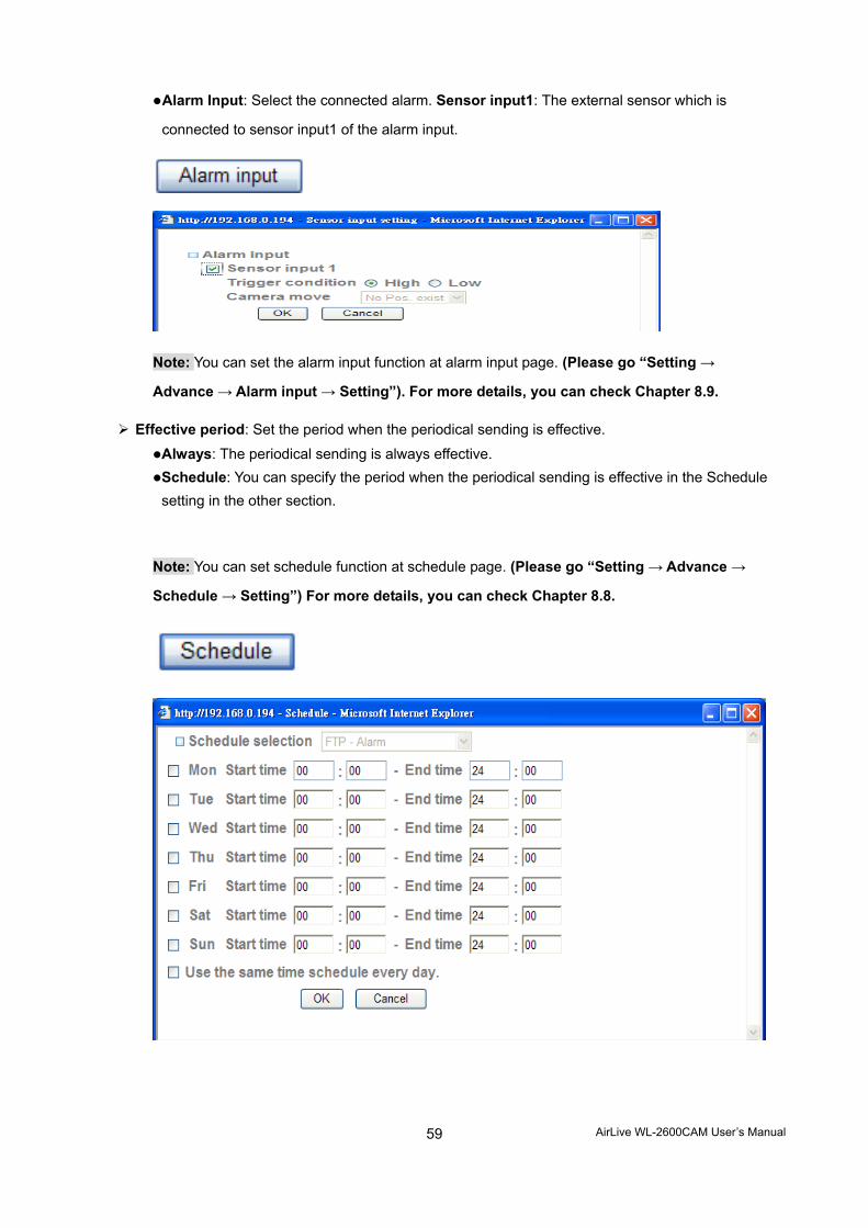
Alarm Input: Select the connected alarm. Sensor input1: The external sensor which is
connected to sensor input1 of the alarm input.
Note: You can set the alarm input function at alarm input page. (Please go “Setting →
Advance → Alarm input → Setting”). For more details, you can check Chapter 8.9.
Effective period: Set the period when the periodical sending is effective.
Always: The periodical sending is always effective. Schedule: You can specify the period when the periodical sending is effective in the Schedule setting in the other section.
Note: You can set schedule function at schedule page. (Please go “Setting → Advance →
Schedule → Setting”) For more details, you can check Chapter 8.8.
AirLive WL-2600CAM User’s Manual
60
7.4.3 Periodical sending
You can set to send an image file to FTP server periodically by selecting On to send the image file to FTP
server linked with setting period.
Image file name: Type the file name of the image sent by SMTP up to 10 alphanumeric
characters, - (hyphen) and _ (under score).
Suffix: Select a suffix to be added to the file name sent by SMTP.
None: The name of the sent file will be the Image file name. Date & time: The date & time suffix is added to the Image file name. The date & time suffix consists of lower two-digits of year (2 digits), month (2 digits), date (2 digits), hour (2 digits), minute (2 digits) and second (2 digits), and consecutive number (2 digits), thus 14-digit number is added to the file name. Sequence number: A consecutive number is added to the Image file name. Sequence number clear: Click Clear and the suffix of the sequence number returns to 1.
Interval: Set the periodical sending is effective interval. Min value is 1 min and Max value is 24
hour.
AirLive WL-2600CAM User’s Manual
61
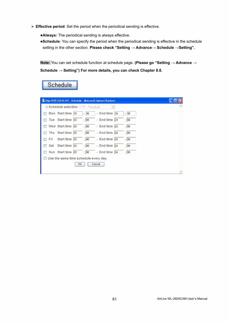
Effective period: Set the period when the periodical sending is effective.
Always: The periodical sending is always effective. Schedule: You can specify the period when the periodical sending is effective in the schedule setting in the other section. Please check “Setting → Advance→ Schedule →Setting”.
Note: You can set schedule function at schedule page. (Please go “Setting → Advance →
Schedule → Setting”) For more details, you can check Chapter 8.8.
AirLive WL-2600CAM User’s Manual
62
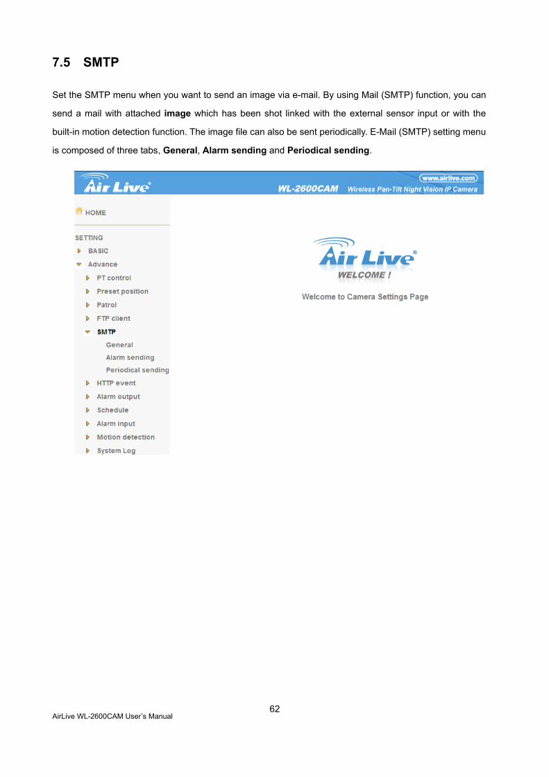
7.5 SMTP
Set the SMTP menu when you want to send an image via e-mail. By using Mail (SMTP) function, you can
send a mail with attached image which has been shot linked with the external sensor input or with the
built-in motion detection function. The image file can also be sent periodically. E-Mail (SMTP) setting menu
is composed of three tabs, General, Alarm sending and Periodical sending.
AirLive WL-2600CAM User’s Manual
63
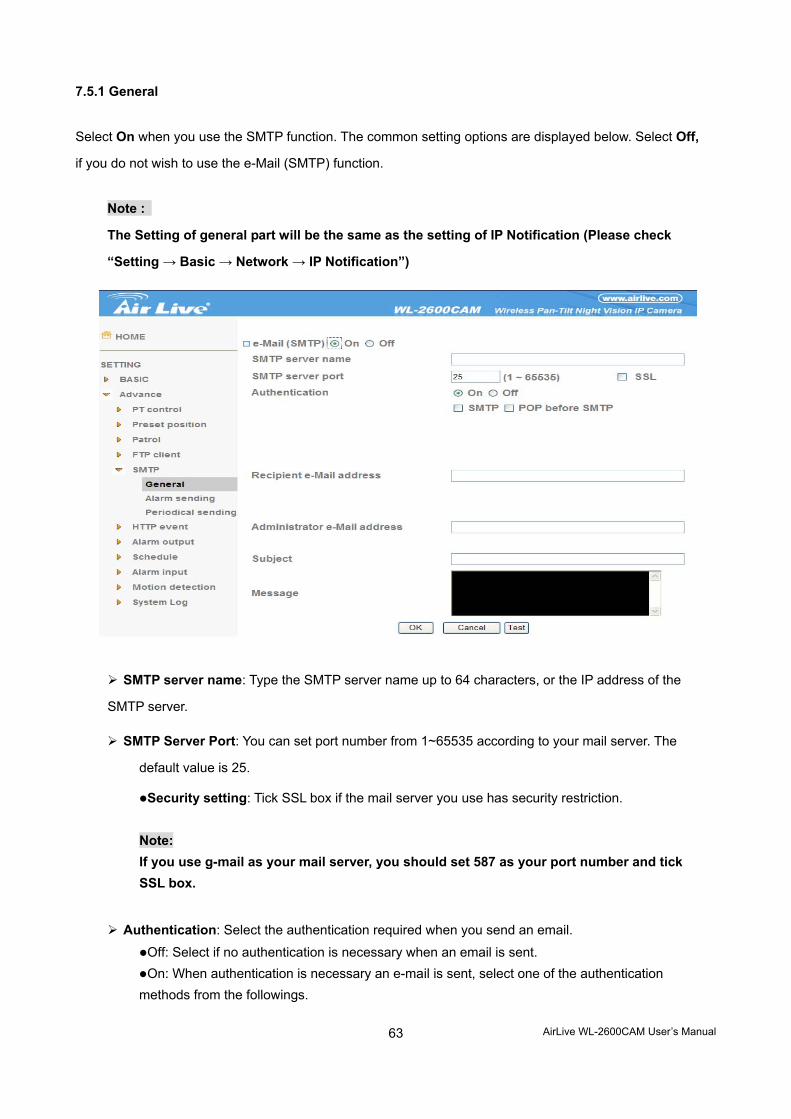
7.5.1 General
Select On when you use the SMTP function. The common setting options are displayed below. Select Off,
if you do not wish to use the e-Mail (SMTP) function.
Note :
The Setting of general part will be the same as the setting of IP Notification (Please check
“Setting → Basic → Network → IP Notification”)
SMTP server name: Type the SMTP server name up to 64 characters, or the IP address of the
SMTP server.
SMTP Server Port: You can set port number from 1~65535 according to your mail server. The
default value is 25.
Security setting: Tick SSL box if the mail server you use has security restriction. Note: If you use g-mail as your mail server, you should set 587 as your port number and tick SSL box.
Authentication: Select the authentication required when you send an email.
Off: Select if no authentication is necessary when an email is sent. On: When authentication is necessary an e-mail is sent, select one of the authentication
methods from the followings.
AirLive WL-2600CAM User’s Manual
64
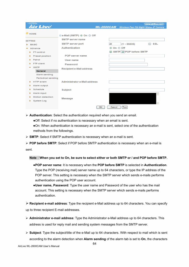
Authentication: Select the authentication required when you send an email.
Off: Select if no authentication is necessary when an email is sent. On: When authentication is necessary an e-mail is sent, select one of the authentication
methods from the followings.
SMTP: Select if SMTP authentication is necessary when an e-mail is sent.
POP before SMTP: Select if POP before SMTP authentication is necessary when an e-mail is
sent.
Note:When you set to On, be sure to select either or both SMTP or / and POP before SMTP.
POP server name: It is necessary when the POP before SMTP is selected in Authentication. Type the POP (receiving mail) server name up to 64 characters, or type the IP address of the POP server. This setting is necessary when the SMTP server which sends e-mails performs authentication using the POP user account. User name, Password: Type the user name and Password of the user who has the mail account. This setting is necessary when the SMTP server which sends e-mails performs authentication.
Recipient e-mail address: Type the recipient e-Mail address up to 64 characters. You can specify
up to three recipient E-mail addresses.
Administrator e-mail address: Type the Administrator e-Mail address up to 64 characters. This
address is used for reply mail and sending system messages from the SMTP server.
Subject: Type the subject/title of the e-Mail up to 64 characters. With respect to mail which is sent
according to the alarm detection when Alarm sending of the alarm tab is set to On, the characters

AirLive WL-2600CAM User’s Manual
65
standing for the sensor type added to the subject.
Message: Type the text of the E-mail up to 384 characters. (A line break is equivalent to 2
characters.)
AirLive WL-2600CAM User’s Manual
66
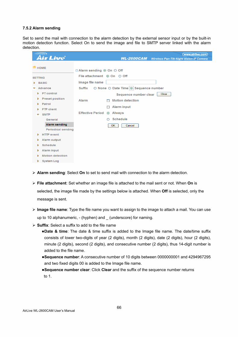
7.5.2 Alarm sending
Set to send the mail with connection to the alarm detection by the external sensor input or by the built-in motion detection function. Select On to send the image and file to SMTP server linked with the alarm detection.
Alarm sending: Select On to set to send mail with connection to the alarm detection.
File attachment: Set whether an image file is attached to the mail sent or not. When On is
selected, the image file made by the settings below is attached. When Off is selected, only the
message is sent.
Image file name: Type the file name you want to assign to the image to attach a mail. You can use
up to 10 alphanumeric, - (hyphen) and _ (underscore) for naming.
Suffix: Select a suffix to add to the file name Date & time: The date & time suffix is added to the Image file name. The date/time suffix consists of lower two-digits of year (2 digits), month (2 digits), date (2 digits), hour (2 digits), minute (2 digits), second (2 digits), and consecutive number (2 digits), thus 14-digit number is added to the file name. Sequence number: A consecutive number of 10 digits between 0000000001 and 4294967295 and two fixed digits 00 is added to the Image file name. Sequence number clear: Click Clear and the suffix of the sequence number returns to 1.
AirLive WL-2600CAM User’s Manual
67
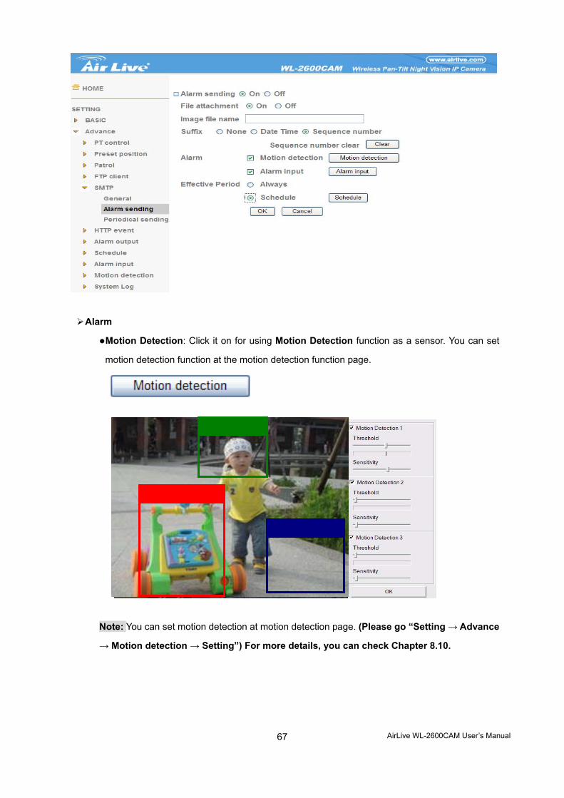
Alarm
Motion Detection: Click it on for using Motion Detection function as a sensor. You can set
motion detection function at the motion detection function page.
Note: You can set motion detection at motion detection page. (Please go “Setting → Advance
→ Motion detection → Setting”) For more details, you can check Chapter 8.10.
AirLive WL-2600CAM User’s Manual
68
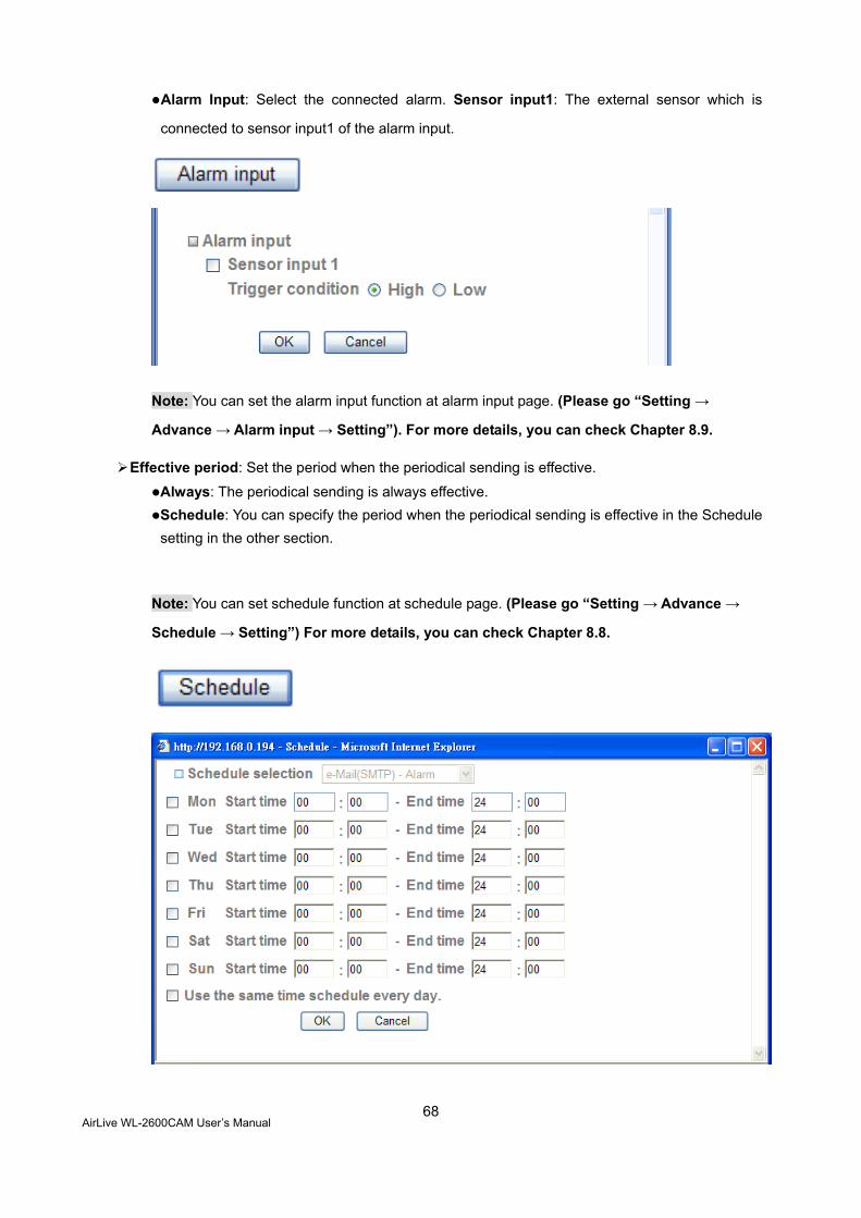
Alarm Input: Select the connected alarm. Sensor input1: The external sensor which is
connected to sensor input1 of the alarm input.
Note: You can set the alarm input function at alarm input page. (Please go “Setting →
Advance → Alarm input → Setting”). For more details, you can check Chapter 8.9.
Effective period: Set the period when the periodical sending is effective.
Always: The periodical sending is always effective. Schedule: You can specify the period when the periodical sending is effective in the Schedule setting in the other section.
Note: You can set schedule function at schedule page. (Please go “Setting → Advance →
Schedule → Setting”) For more details, you can check Chapter 8.8.
AirLive WL-2600CAM User’s Manual
69
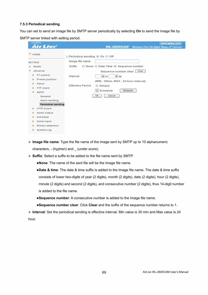
7.5.3 Periodical sending
You can set to send an image file by SMTP server periodically by selecting On to send the image file by
SMTP server linked with setting period.
Image file name: Type the file name of the image sent by SMTP up to 10 alphanumeric
characters, - (hyphen) and _ (under score).
Suffix: Select a suffix to be added to the file name sent by SMTP.
None: The name of the sent file will be the Image file name.
Date & time: The date & time suffix is added to the Image file name. The date & time suffix
consists of lower two-digits of year (2 digits), month (2 digits), date (2 digits), hour (2 digits),
minute (2 digits) and second (2 digits), and consecutive number (2 digits), thus 14-digit number
is added to the file name.
Sequence number: A consecutive number is added to the Image file name.
Sequence number clear: Click Clear and the suffix of the sequence number returns to 1.
Interval: Set the periodical sending is effective interval. Min value is 30 min and Max value is 24
hour.
AirLive WL-2600CAM User’s Manual
70
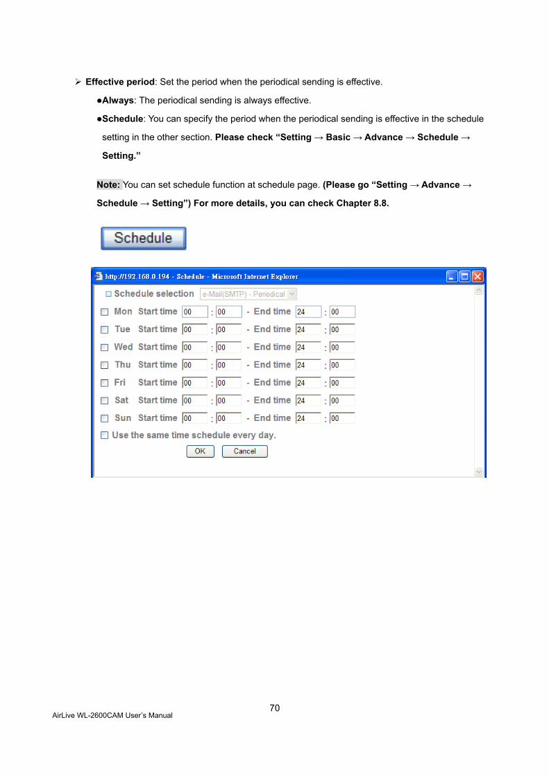
Effective period: Set the period when the periodical sending is effective.
Always: The periodical sending is always effective.
Schedule: You can specify the period when the periodical sending is effective in the schedule
setting in the other section. Please check “Setting → Basic → Advance → Schedule →
Setting.”
Note: You can set schedule function at schedule page. (Please go “Setting → Advance →
Schedule → Setting”) For more details, you can check Chapter 8.8.
AirLive WL-2600CAM User’s Manual
71
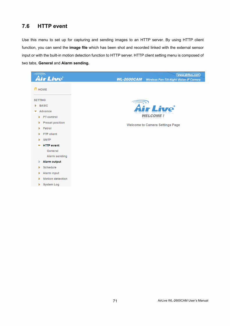
7.6 HTTP event
Use this menu to set up for capturing and sending images to an HTTP server. By using HTTP client
function, you can send the image file which has been shot and recorded linked with the external sensor
input or with the built-in motion detection function to HTTP server. HTTP client setting menu is composed of
two tabs, General and Alarm sending.
AirLive WL-2600CAM User’s Manual
72
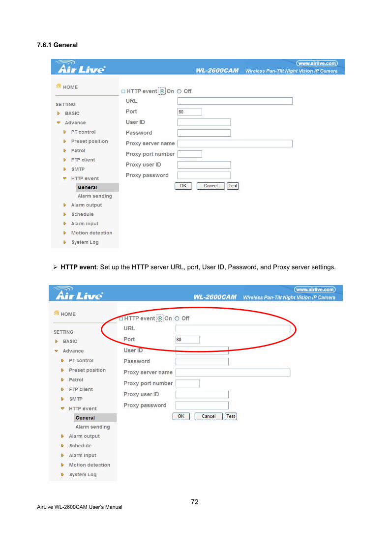
7.6.1 General
HTTP event: Set up the HTTP server URL, port, User ID, Password, and Proxy server settings.
For example: URL: 192.168.1.7/cgi-bin/operator/ptzset
Note: The setting of URL should be the same as CGI
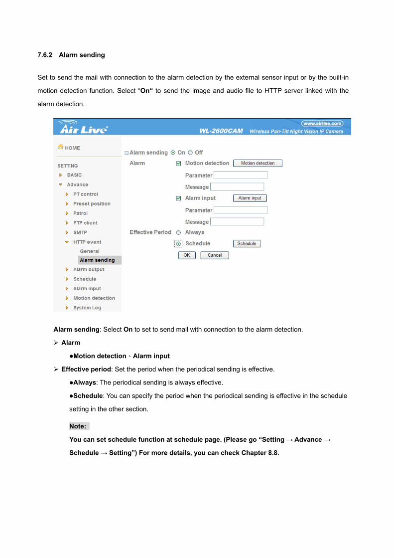
7.6.2 Alarm sending
Set to send the mail with connection to the alarm detection by the external sensor input or by the built-in
motion detection function. Select “On“ to send the image and audio file to HTTP server linked with the
alarm detection.
Alarm sending: Select On to set to send mail with connection to the alarm detection.
Alarm
Motion detection、Alarm input
Effective period: Set the period when the periodical sending is effective.
Always: The periodical sending is always effective.
Schedule: You can specify the period when the periodical sending is effective in the schedule
setting in the other section.
Note:
You can set schedule function at schedule page. (Please go “Setting → Advance →
Schedule → Setting”) For more details, you can check Chapter 8.8.
AirLive WL-2600CAM User’s Manual
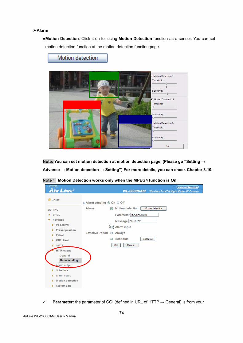
74
Alarm
Motion Detection: Click it on for using Motion Detection function as a sensor. You can set
motion detection function at the motion detection function page.
Note: You can set motion detection at motion detection page. (Please go “Setting →
Advance → Motion detection → Setting”) For more details, you can check Chapter 8.10.
Note: Motion Detection works only when the MPEG4 function is On.
Parameter: the parameter of CGI (defined in URL of HTTP → General) is from your
target device. For example, move=down.
Message: message will show up in the form of Message = PTZ down. If your target
device didn’t support the parameter of message, you can’t see the message. So you
can just take the message as a note. For example: PTZ down.
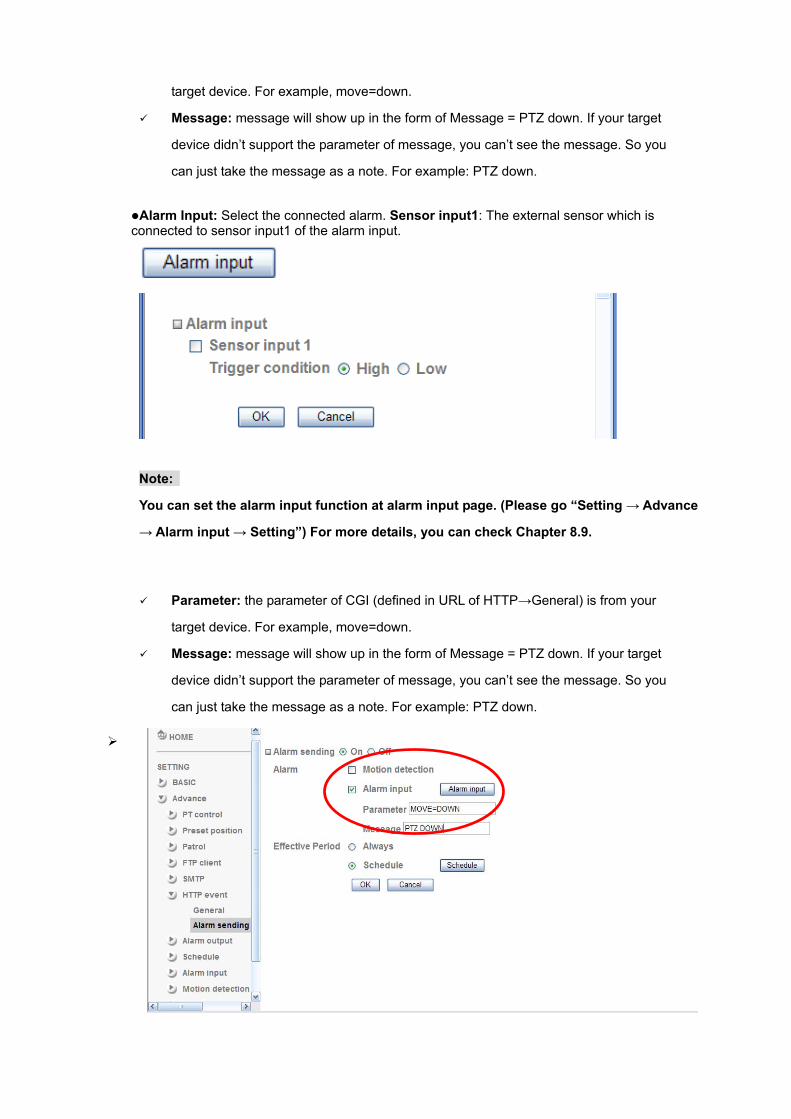
Alarm Input: Select the connected alarm. Sensor input1: The external sensor which is
connected to sensor input1 of the alarm input.
Note:
You can set the alarm input function at alarm input page. (Please go “Setting → Advance
→ Alarm input → Setting”) For more details, you can check Chapter 8.9.
Parameter: the parameter of CGI (defined in URL of HTTP→General) is from your
target device. For example, move=down.
Message: message will show up in the form of Message = PTZ down. If your target
device didn’t support the parameter of message, you can’t see the message. So you
can just take the message as a note. For example: PTZ down.
AirLive WL-2600CAM User’s Manual
76
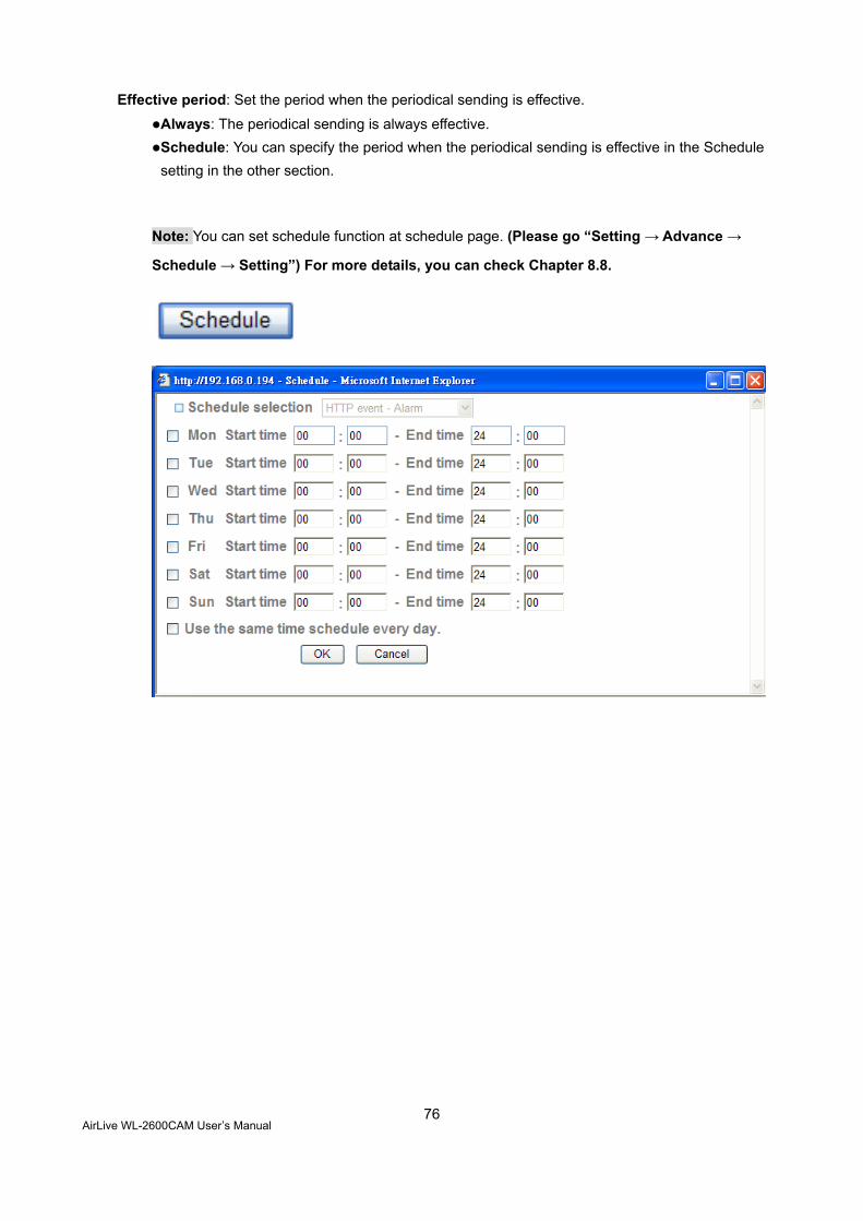
Effective period: Set the period when the periodical sending is effective.
Always: The periodical sending is always effective. Schedule: You can specify the period when the periodical sending is effective in the Schedule setting in the other section.
Note: You can set schedule function at schedule page. (Please go “Setting → Advance →
Schedule → Setting”) For more details, you can check Chapter 8.8.
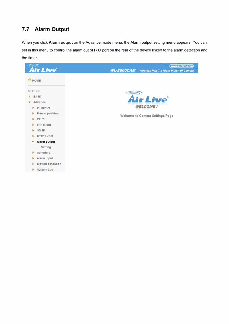
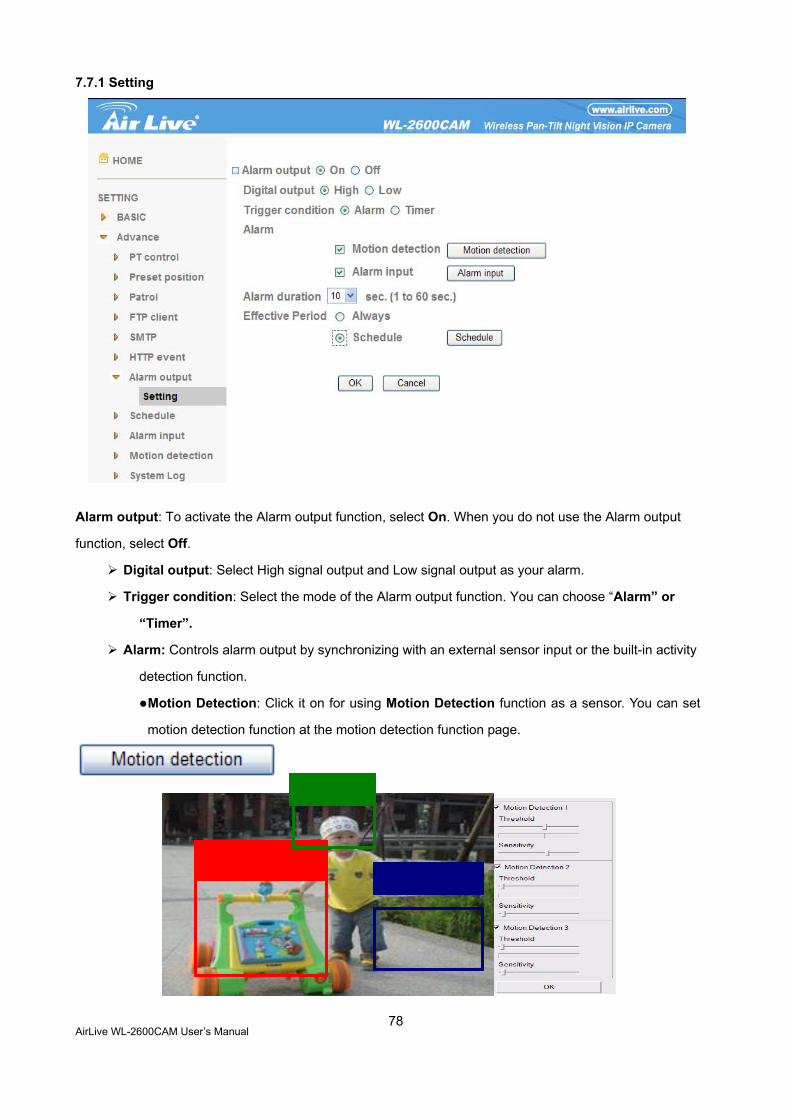
7.7 Alarm Output When you click Alarm output on the Advance mode menu, the Alarm output setting menu appears. You can
set in this menu to control the alarm out of I / O port on the rear of the device linked to the alarm detection and
the timer.
AirLive WL-2600CAM User’s Manual
78
7.7.1 Setting
Alarm output: To activate the Alarm output function, select On. When you do not use the Alarm output
function, select Off.
Digital output: Select High signal output and Low signal output as your alarm.
Trigger condition: Select the mode of the Alarm output function. You can choose “Alarm” or
“Timer”.
Alarm: Controls alarm output by synchronizing with an external sensor input or the built-in activity
detection function.
Motion Detection: Click it on for using Motion Detection function as a sensor. You can set
motion detection function at the motion detection function page.
Note: You can set motion detection at motion detection page. (Please go “Setting →
Advance → Motion detection → Setting”). For more details, you can check Chapter 8.10.
Note:Motion Detection works only when the Video mode is set to MPEG4 and the
Cropping is set to Off.
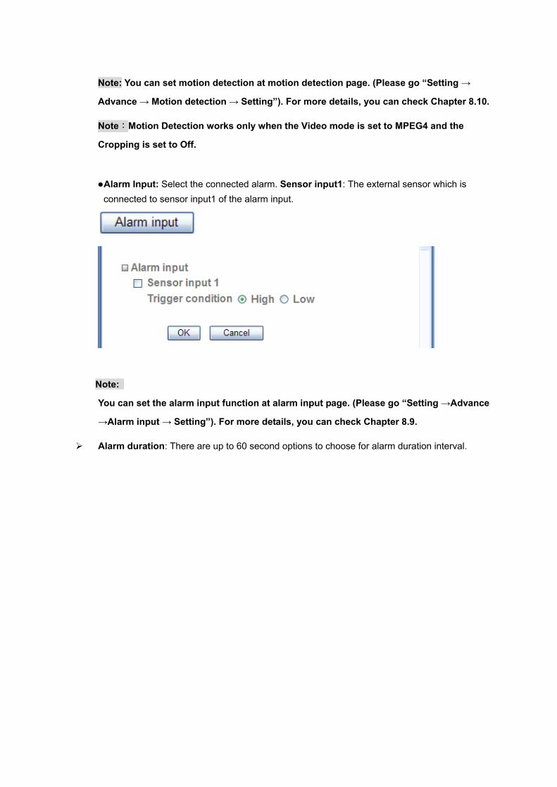
Alarm Input: Select the connected alarm. Sensor input1: The external sensor which is connected to sensor input1 of the alarm input.
Note:
You can set the alarm input function at alarm input page. (Please go “Setting →Advance
→Alarm input → Setting”). For more details, you can check Chapter 8.9.
Alarm duration: There are up to 60 second options to choose for alarm duration interval.
AirLive WL-2600CAM User’s Manual
80
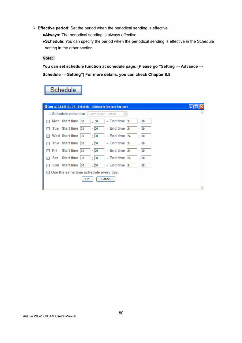
Effective period: Set the period when the periodical sending is effective.
Always: The periodical sending is always effective. Schedule: You can specify the period when the periodical sending is effective in the Schedule setting in the other section.
Note:
You can set schedule function at schedule page. (Please go “Setting → Advance →
Schedule → Setting”) For more details, you can check Chapter 8.8.
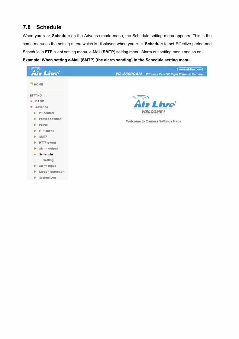
7.8 Schedule When you click Schedule on the Advance mode menu, the Schedule setting menu appears. This is the
same menu as the setting menu which is displayed when you click Schedule to set Effective period and
Schedule in FTP client setting menu, e-Mail (SMTP) setting menu, Alarm out setting menu and so on.
Example: When setting e-Mail (SMTP) (the alarm sending) in the Schedule setting menu.
AirLive WL-2600CAM User’s Manual
82
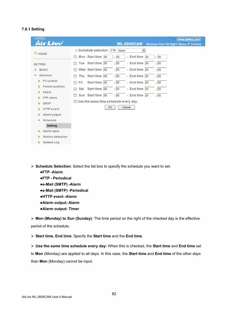
7.8.1 Setting
Schedule Selection: Select the list box to specify the schedule you want to set. FTP -Alarm FTP - Periodical e-Mail (SMTP) -Alarm e-Mail (SMTP) -Periodical HTTP event -Alarm Alarm output- Alarm Alarm output- Timer
Mon (Monday) to Sun (Sunday): The time period on the right of the checked day is the effective
period of the schedule.
Start time, End time: Specify the Start time and the End time.
Use the same time schedule every day: When this is checked, the Start time and End time set
to Mon (Monday) are applied to all days. In this case, the Start time and End time of the other days
than Mon (Monday) cannot be input.
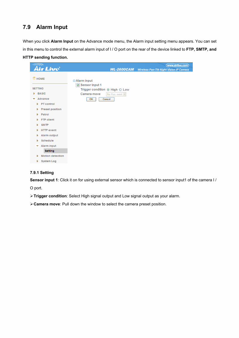
7.9 Alarm Input
When you click Alarm Input on the Advance mode menu, the Alarm input setting menu appears. You can set
in this menu to control the external alarm input of I / O port on the rear of the device linked to FTP, SMTP, and
HTTP sending function.
7.9.1 Setting
Sensor input 1: Click it on for using external sensor which is connected to sensor input1 of the camera I /
O port.
Trigger condition: Select High signal output and Low signal output as your alarm.
Camera move: Pull down the window to select the camera preset position.
AirLive WL-2600CAM User’s Manual
84
7.10 Motion Detection There are three Motion Detection functions as sensors to set for different detecting zones. Each one has
Threshold and Sensitivity inputs which you can adjust to specific zone sequentially. Motion Detection
function can support to FTP, SMTP and Alarm output for capturing and sending images or starting alarm
output.
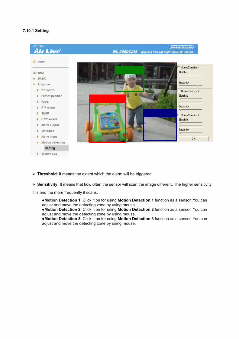
7.10.1 Setting
Threshold: It means the extent which the alarm will be triggered.
Sensitivity: It means that how often the sensor will scan the image different. The higher sensitivity
it is and the more frequently it scans.
Motion Detection 1: Click it on for using Motion Detection 1 function as a sensor. You can adjust and move the detecting zone by using mouse.
Motion Detection 2: Click it on for using Motion Detection 2 function as a sensor. You can adjust and move the detecting zone by using mouse.
Motion Detection 3: Click it on for using Motion Detection 3 function as a sensor. You can adjust and move the detecting zone by using mouse.
AirLive WL-2600CAM User’s Manual
86
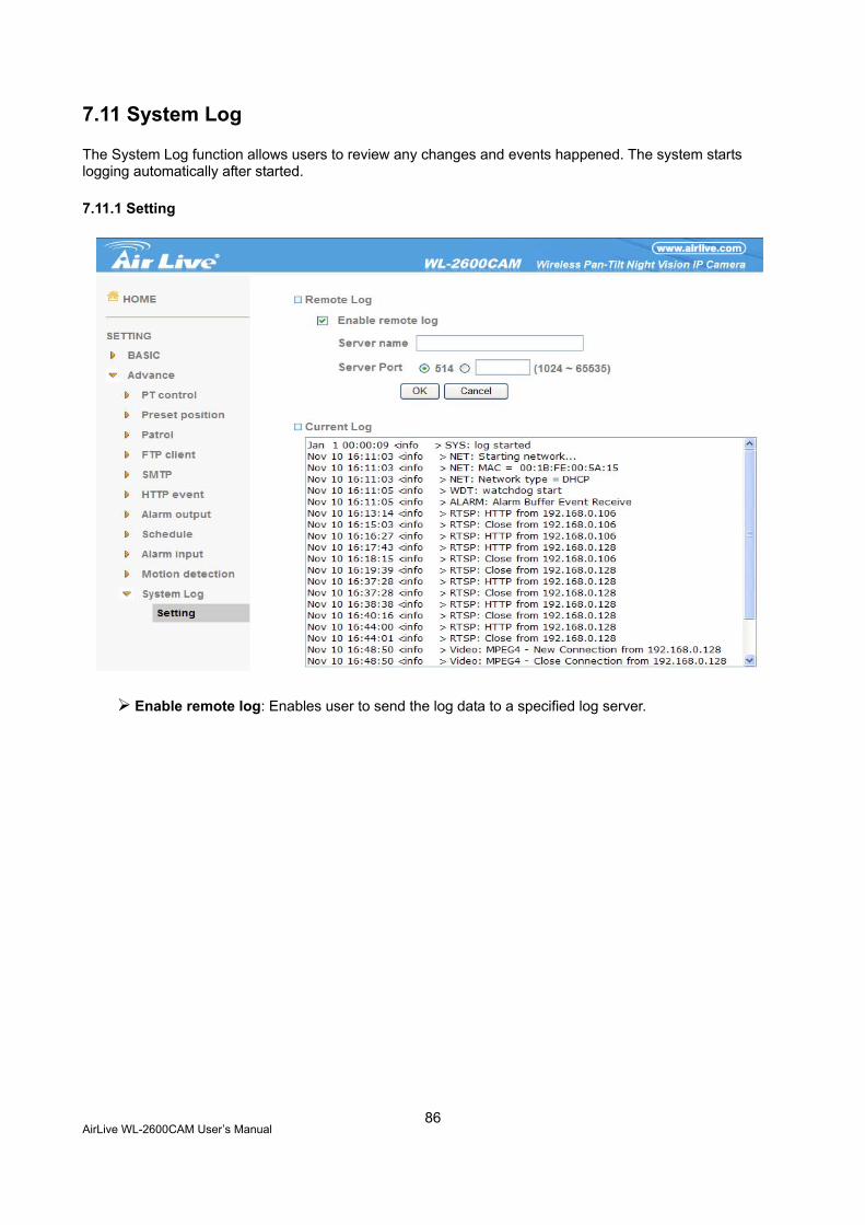
7.11 System Log
The System Log function allows users to review any changes and events happened. The system starts logging automatically after started.
7.11.1 Setting
Enable remote log: Enables user to send the log data to a specified log server.
CHAPTER 8 : APPENDIX
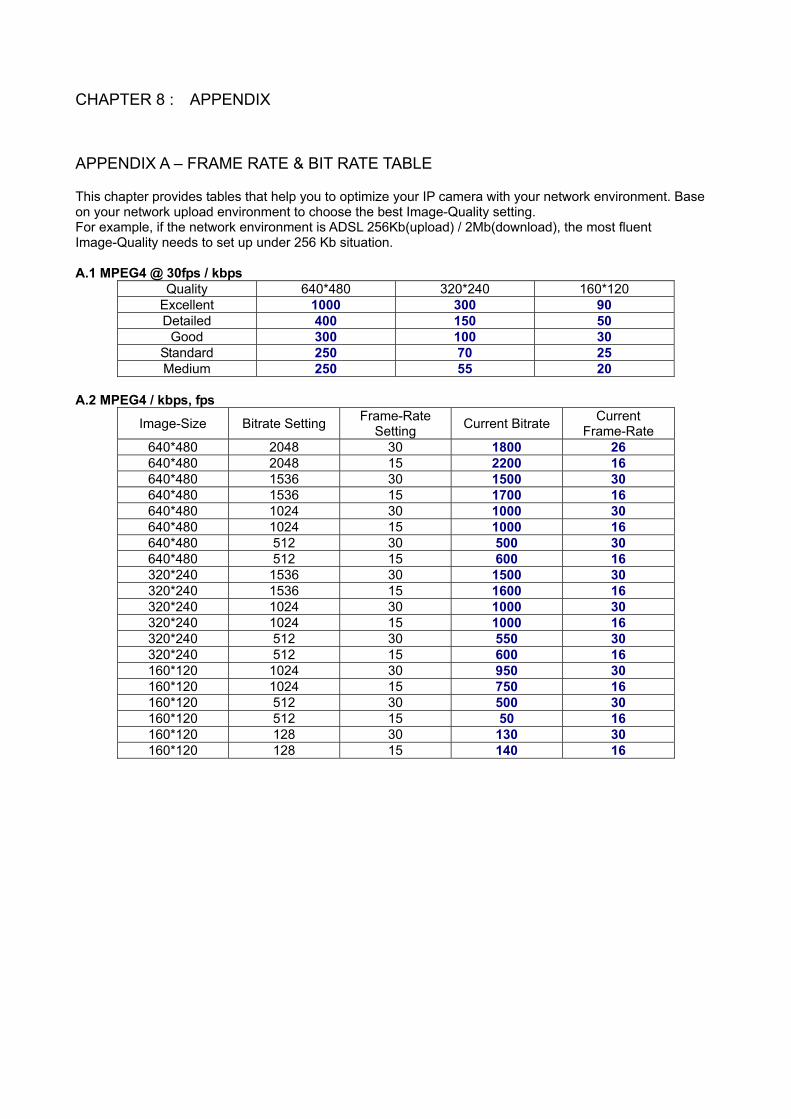
APPENDIX A – FRAME RATE & BIT RATE TABLE This chapter provides tables that help you to optimize your IP camera with your network environment. Base on your network upload environment to choose the best Image-Quality setting. For example, if the network environment is ADSL 256Kb(upload) / 2Mb(download), the most fluent Image-Quality needs to set up under 256 Kb situation. A.1 MPEG4 @ 30fps / kbps
Quality 640*480 320*240 160*120 Excellent 1000 300 90 Detailed 400 150 50
Good 300 100 30 Standard 250 70 25 Medium 250 55 20
A.2 MPEG4 / kbps, fps
Image-Size Bitrate Setting Frame-Rate Setting Current Bitrate Current
Frame-Rate 640*480 2048 30 1800 26 640*480 2048 15 2200 16 640*480 1536 30 1500 30 640*480 1536 15 1700 16 640*480 1024 30 1000 30 640*480 1024 15 1000 16 640*480 512 30 500 30 640*480 512 15 600 16 320*240 1536 30 1500 30 320*240 1536 15 1600 16 320*240 1024 30 1000 30 320*240 1024 15 1000 16 320*240 512 30 550 30 320*240 512 15 600 16 160*120 1024 30 950 30 160*120 1024 15 750 16 160*120 512 30 500 30 160*120 512 15 50 16 160*120 128 30 130 30 160*120 128 15 140 16
AirLive WL-2600CAM User’s Manual
88
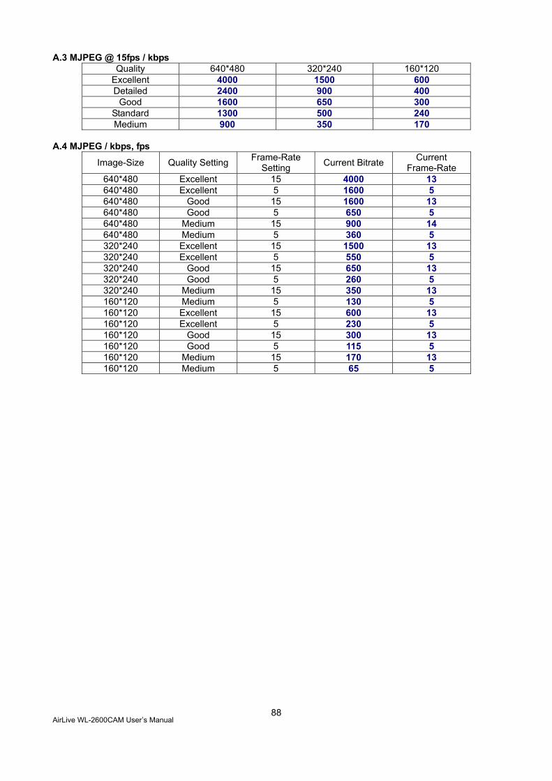
A.3 MJPEG @ 15fps / kbps Quality 640*480 320*240 160*120
Excellent 4000 1500 600 Detailed 2400 900 400
Good 1600 650 300 Standard 1300 500 240 Medium 900 350 170
A.4 MJPEG / kbps, fps
Image-Size Quality Setting Frame-Rate Setting Current Bitrate Current
Frame-Rate 640*480 Excellent 15 4000 13 640*480 Excellent 5 1600 5 640*480 Good 15 1600 13 640*480 Good 5 650 5 640*480 Medium 15 900 14 640*480 Medium 5 360 5 320*240 Excellent 15 1500 13 320*240 Excellent 5 550 5 320*240 Good 15 650 13 320*240 Good 5 260 5 320*240 Medium 15 350 13 160*120 Medium 5 130 5 160*120 Excellent 15 600 13 160*120 Excellent 5 230 5 160*120 Good 15 300 13 160*120 Good 5 115 5 160*120 Medium 15 170 13 160*120 Medium 5 65 5
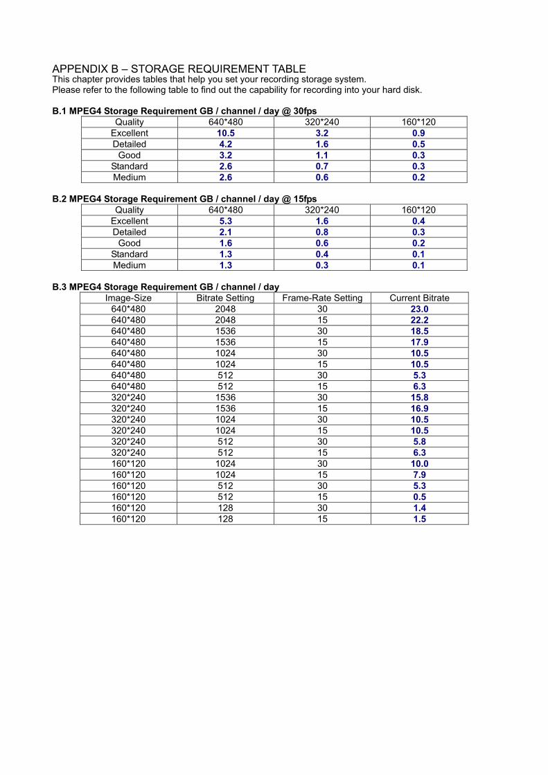
APPENDIX B – STORAGE REQUIREMENT TABLE This chapter provides tables that help you set your recording storage system. Please refer to the following table to find out the capability for recording into your hard disk. B.1 MPEG4 Storage Requirement GB / channel / day @ 30fps
Quality 640*480 320*240 160*120 Excellent 10.5 3.2 0.9 Detailed 4.2 1.6 0.5
Good 3.2 1.1 0.3 Standard 2.6 0.7 0.3 Medium 2.6 0.6 0.2
B.2 MPEG4 Storage Requirement GB / channel / day @ 15fps
Quality 640*480 320*240 160*120 Excellent 5.3 1.6 0.4 Detailed 2.1 0.8 0.3
Good 1.6 0.6 0.2 Standard 1.3 0.4 0.1 Medium 1.3 0.3 0.1
B.3 MPEG4 Storage Requirement GB / channel / day
Image-Size Bitrate Setting Frame-Rate Setting Current Bitrate 640*480 2048 30 23.0 640*480 2048 15 22.2 640*480 1536 30 18.5 640*480 1536 15 17.9 640*480 1024 30 10.5 640*480 1024 15 10.5 640*480 512 30 5.3 640*480 512 15 6.3 320*240 1536 30 15.8 320*240 1536 15 16.9 320*240 1024 30 10.5 320*240 1024 15 10.5 320*240 512 30 5.8 320*240 512 15 6.3 160*120 1024 30 10.0 160*120 1024 15 7.9 160*120 512 30 5.3 160*120 512 15 0.5 160*120 128 30 1.4 160*120 128 15 1.5


![AirLive WL-5470AP User · PDF fileWL-5470AP CE Declaration Statement Country Declaration Country Declaration cs Česky [Czech] OvisLink Corp. tímto prohlašuje, že tento WL-5470AP](https://img.dokumen.tips/doc/110x75/5a767e437f8b9a1b688d4630/airlive-wl-5470ap-user-manual-wl-5470ap-ce-declaration-statement-country-declaration.jpg)