Embed Size (px)
Citation preview
AIRCRAFT SHAPES AND THEIR AERODYNAMICS
FOR FLIGHT AT SUPERSONIC SPEEDS
By D. It L'CIEMANN
Royal Aircraft Establishment (Farnborough)
Summary — For the task of achieving a given flight range, and with some overall assump-tions about the structural and propulsive elements and a simple set of supersonic aero-dynamics, box sizes with certain relations between span and length are determined, intowhich a supersonic aircraft must fit. Various layouts are then discussed, with suitabletypes of flow which not only give the required performance but are also acceptable forengineering purposes. The yawed wing, the swept wing-fuselage combination, and theslender wing are shown to offer potential solutions, each of these designed to have thesame type of flow throughout its flight range. Slender wing aircraft are considered inmore detail and some theoretical and experimental results are given.
• Introduction
As seen in retrospect, the first 50 years of aeronautical engineering havebeen dominated by one characteristic shape of the practical aeroplane
on the one hand and Prandtl's boundary-layer and aerofoil theories on
the other. With these two aspects, aerodynamic theory and aircraft design
most happily complemented one another. It is now time to realize that
the classical aircraft shape constitutes a highly restrictive class of bodies
and that classical aerodynamics amounts to the study of one special case
of general fluid flow only. The future of aeronautics, with the pros-
pect of almost unlimited available power and attainable speeds, there-
fore. requires not only the extension of existing theories to include thermo-
dynamic and real-gas effects; it also requires the introduction and thestudy of new characteristic shapes and new types of flow, which again
should suit one another as perfectly as was true for the classical aircraftand classical aerodynamics.
To explain the procedure we adopt in arriving at such new shapes,now for supersonic flight speeds, we begin with a brief recapitulation
of how this procedure can be applied to the classical aircraft, for the
simplest task: that to achieve a given flight range. After that, we are going
to discuss the changes brought about by new means of propulsion and
by the new set of supersonic aerodynamics. This is followed by a discussion
[221
222 D. KtiCHEMANN
of some possible solutions, which include swept wing-fuselage combi-nations, yawed wings, and slender wings. Only the latter involve an entirelynew type of flow and this is discussed in some detail.
It is gratefully acknowledged that many of the findings reported hereare the results of a concerted research effort on a large scale, in whichmost British aircraft firms and research establishments have been engagedover the last 3 or 4 years. The responsibility for the presentation and theconclusions is, of course, the author's.
2. Prolegomena Concerning the Classical Aircraft
We consider the simplest and most obvious task which an aircraft isrequired to perform, namely, to fly from one place to another and soto achieve a given flight range. Hence, according to Bréguet, a certainvalue of
Range = /—V,x(L.D)xln (1171,.W.1-1 (1 )
must be obtained. This equation contains a structural component—theratio between the initial weight and the final weight, including fuel; anaerodynamic component the ratio LD between lift and drag at cruise;a speed term—the cruising speed V0; and a propulsion term—taken hereas the specific impulse, I, of the powerplant; I is inversely proportionalto the specific fuel consumption. It is evident from Bréguet's equationalone that aircraft design is a compromise between structural, propulsive,and aerodynamic ingredients. However, our contention is that, with onlya rudimentary knowledge of the structural and propulsive components,the aerodynamic component alone is sufficient to determine the generallayout of the vehicle in the cases considered.
We now introduce some restrictions and stipulate that the aircraftshould fly at subsonic speeds and, further, that it should be so designedthat the means for providing stowage volume, lift, and propulsion areseparate. If propulsion is to be obtained by propellers driven by pistonengines, then we are concerned with what are basically constant-horse-power engines so that for each individual engine the product of / andVo remains roughly constant, not / itself. Again, for the whole familyof piston-propeller engines, a higher required thrust at some higher flightspeed implies a higher specific fuel consumption and a lower specificimpulse so that, to a first order, the value of /x170 may be taken as lyingwithin a certain band, independent of the flight speed. On the structuralside, it is sufficient to assume it to be known that no drastic changes inthe weight factor occur with flight speed so that the value of W :IV canbe taken to lie within a certain band again, somewhere between 1 and2, say. We are then left with the aerodynamic side where it is required
Aircraft Shapes and their Aerodynamics
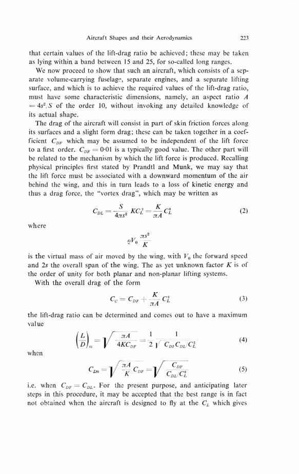
that certain values of the lift-drag ratio be achieved; these may be takenas lying within a band between 15 and 25, for so-called long ranges.
We now proceed to show that such an aircraft, which consists of a sep-arate volume-carrying fuselage, separate engines, and a separate lifting
surface, and which is to achieve the required values of the lift-drag ratio,
must have some characteristic dimensions, namely, an aspect ratio A
— 4s', S of the order 10, without invoking any detailed knowledge of
its actual shape.
The drag of the aircraft will consist in part of skin friction forces alongits surfaces and a slight form drag; these can be taken together in a coef-
ficient C„ which may be assumed to be independent of the lift forceto a first order. C„ = 0.01 is a typically good value. The other part will
be related to the mechanism by which the lift force is produced. Recallingphysical principles first stated by Prandtl and Munk, we may say that
the lift force must be associated with a downward momentum of the air
behind the wing, and this in turn leads to a loss of kinetic energy andthus a drag force, the "vortex drag'', which may be written as
CDL KCZ - (2)
where
is the virtual mass of air moved by the wing, with Vo the forward speed
and 2s the overall span of the wing. The as yet unknown factor K is ofthe order of unity for both planar and non-planar lifting systems.
With the overall drag of the form
C. — - Cj2 (3) :TA
the lift-drag ratio can be determined and comes out to have a maximum
value
f A1
4;CDF 2 j CDIICDL
when
:TA C CD,- -
K„
C„
i.e. when C„, = CD„. For the present purpose, and anticipating later
steps in this procedure, it may be accepted that the best range is in fact not obtained when the aircraft is designed to fly at the C, which gives

224 D. KCCIIEMANN
the maximum value of LID but that engine and weight considerations
lead one to fly at a CL-value slightly below that, typically at
CL= I 2 CL„ = - I 2 1/ - CDF2 ' 2 r K
in which case
L\ / 2:TAD 9 \ Dj„, 9K CDF
Because it is immaterial to the present investigation which value of LID
is takcn, it is this value of LID that is considered in most numerical
examples, unless otherwise stated.
For a required value of LID, equation (7) may be regarded as deter-
mining the aspect ratio which is needed:
A = KCDF(L)29D
•
Typical values of A obtained in this way with K= 1 are:
Values of A (and of C1)
15
6
for LID —
when CDF :-- 0-01 3 (0-22)
25
9(0.38)(0-30)
when Cor 0.015 5913(0.34)(0.45)(0.56)
On the whole, these values are of the order of 10 (i.e., not 1, nor 100),and even drastic changes in the values of K and GI, cannot alter this
basic result.*
Proceeding further with this hypothetical aerodynamic development of
the classical aircraft, we now come to the aerodynamic design problem,
namely, to investigate Whether shapes can be found which have, in fact,
the assumed physical properties and whether the type of flow implied
is usable in engineering practice, i.e., whether it is steady and control-
lable and whether it can be maintained also in off-design conditions,
preferably throughout the whole flight range, limiting our attention from
now on to relatively thin wings, the spanwise extent of which is of an
* It should be borne in mind that equation (8) determines a "minimum aspect ratiofor a given set of conditions and that the designer is at liberty to choose a higher aspectratio. In that case, a higher payload may be carried provided that the saving in fueldue to the higher aspect ratio was greater than the cost in structure weight of achieving it.In the present context, this only strengthens the conclusion that classical aircraft arelikely to have wings of moderate or large aspect ratio.
Aircraft Shapes and their Aerodynamics 225
order greater than its streamwise extent, and to which a volume—pro-viding fuselage and engines can be attached without any first-order inter-
ference. It will suffice here to recall that classical aerodynamics in the
dual form of classical aerofoil theory and boundary-layer theory is admir-
ably suited to deal with the wings of high aspect ratio with classical aerofoil
sections that emerged, and fits the required conditions perfectly.
In particular, it is recalled that the shapes under consideration allow
the assumption to be made that the flow over the wing is dominated bythe characteristics of a two-dimensional flow in streamwise planes; and
that the flow over the fuselage is basically that past an essentially non-
lifting body of revolution. Further, there exists a two-dimensional type
of flow in which viscous effects are confined to a thin boundary layer
and wake. The body which gives rise to this flow possesses a sharp trailing
edge so that the separation is confined and fixed to the trailing edge.
Therefore, the trailing vorticity which is associated with the lift force
is shed in the form of an essentially planar sheet. Also, it is possible to
control this flow and its associated forces and moments so as to achieve
a sufficient range of practical flight manoeuvres while keeping the sep-
aration at the wing trailing edge and, thus, maintaining essentially the
same type of flow throughout. This type of flow also gives the best per-
formance and handling qualities, compared with any other possible flow,
and it has been generally agreed for 50 years that the greatest efforts should
be made to maintain it. For a further discussion of the aerodynamic design
problem, we refer to a paper by Maskellm and for an account of the
relevant theories and observations in this light to a recent book by
Thwaitest2).In the present context, we note that within the aerodynamic system
with the classical type of flow, equation (2) and the subsequent relations
are very good approximations to the observed facts so that the procedure
adopted is both consistent and realistic. Also, none of the often drastic
developments in the fields of structural design, propellers and piston
engines have changed the fundamental aerodynamic characteristics of
the family of aircraft so obtained. Indeed, so successful was this family
of aircraft that many of its features have come to be regarded as funda-
mental to any aircraft, whether supersonic, hypersonic, or of the VTO
type, and, when jet engines made supersonic flight possible, it was assumed
as a matter of course that a volume-providing non-lifting fuselage wouldhave to be attached to a separate thin wing to do the lifting, with separate
engines for propulsion. On the aerodynamic side, we thus proceeded
automatically to investigate bodies of revolution and thin two-dimensional
aerofoils at supersonic speeds and although it was found that their prop-
erties radically differed from those which, at low speeds, had led to the
15

226 D. KOCHEMANN
classical aircraft, missiles and aircraft of the same basic layout were, andstill are, actively pursued. As a consequence, we had to live with whathas been described as "lousy flows".
We believe that this development was a mistake and propose, therefore,to start again and investigate whether a procedure similar to that justexplained but with different initial assumptions may lead us to morenatural and more efficient solutions for flight at supersonic speeds.
3. New Aerodynamic Requirements
We still consider the simple task of achieving a given flight range, ac-cording to equation (1), but now at mainly supersonic speeds. There isno reason to suppose that the structural term will radically change byan order of magnitude. But the propulsion term differs fundamentallyfrom that of the propeller-piston engine combination if we now considerjet engines that are the outcome of the one major development withoutwhich supersonic flight could not be contemplated. For jet-engine pro-pulsion, the specific impulse, and the specific fuel consumption, stayroughly constant over a certain speed range for each individual engineas well as for the whole family of eneines. They are basically "constant-thrust" rather than "constant-power" engines. Thus the value of I inequation (1) lies within a certain band, independent of the flight speed.As a consequence on the aerodynamic side, the product Vx(LID) orR= Mx(LID) is required to have certain N,alues rather than LID itself.
In principle, this aerodynamic requirement may be considered to applythrough the whole Mach number range where air-breathing engines canbe used, up to M = 10 perhaps. We must be prepared to find, however,that additional conditions, under which the given flight range is to beachieved, may be made such as those which may result from considerationsof aerodynamic heating. Further, engine performance is likely to changewith Mach number, to a second order, and while we can say that typicalvalues of R= MLID lie between 15 and 30, a practical variation of therequired value of LID with Mach number may be less drastic. As a roughguide, values of R= 4 (M+3) may be regarded as "good" ones for longranges of the transatlantic order up to M = 5 or 6, say. This gives
LID 14 10• 8Î 7 6
for M 1.2 2Î 3' 4 6
Slightly lower values can probably be tolerated. The drop in the requiredvalue of LID with Mach number has far-reaching consequences on thelayout of the aircraft.

Aircraft Shapes and their Aerodynamics 227
4. A Set of Supersonic Aerodynamics
Whereas we can see already that the reduction in the required value ofL D at supersonic speeds should lead to smaller values of the aspect ratio—A would be less than q at M = 2 if equation (8) would still apply, withK = 1 and CDF = 0.01 — still another aspect demands our attention,namely, that a new set of aerodynamics is needed, because equation (8)and its basis can no longer be considered adequate. This must take accountof the fact that wave drag terms appear, resulting from the volume andfrom the lift of the aircraft and depending primarily on the lengths ofthe volume and of the lifting surface. Most of what now follows will beexplained by means of the simplest example where the length of the volumeis the same as that of the lifting surface, in contrast to common practice.This is also the most realistic case because we shall find that it is verydifficult, if not impossible, to make a volume-providing body non-liftingand to provide a lifting surface without volume. In this sense, most con-figurations cannot help being such that volume and lifting surface are"integrated".
A suitable set of eeometric parameters is needed first. Apart from thewing area, S, three further parameters must account for the overalllenght, 1, the overall span, 2s, and the overall volume, V, of the wingor body, whatever its shape. Following Collingbourne, a consistent andconvenient set is given by:
the semispan-length ratio
p = a planform shape parameter2s1
VT — a volume parameter
S312
p is the ratio betw een the wing plan-area and the area of the circumscribedrectanele with the same span and length. p =112 for wings of delta plan-form. Note that the aspect ratio is then
A 2 Sfl— (11)
It is not an independent parameter. A is increased by increasing the semi-span-length ratio for constant p or by decreasing the planform shapeparameter for constant sll.
Four principal terms contribute to the overall drag of the aircraft inthe set of aerodynamics considered here:
(1) Skin-friction drag along the surface of the aircraft, leading to thedrag coefficient CDF as before.
15.

228 D. KÜCHEMANN
(2) Wave drag resulting from the volume of the aircraft. This canconveniently be defined as:
128 V2 512 \2
T2 P2—. 1) K°(12)
where K, is a non-dimensional factor which can be determined by theory orexperiment. Equation (12) takes account of the fact that V2 and 1// arethe dominant factors for many configurations; the value of K, then dependsprimarily on the shape of the body enclosing the given overall volume.A value for K0 of unity is typical for well-shaped bodies of revolution;in fact, K, = 1 corresponds to the Sears-Haack body.
(3) Wave drag resulting from the lift on the aircraft. This can be writtenin the form:
2 1CDLW =
S C- - L K C2 p 132 K
Again, it is convenient to isolate the dominant factors cy,, 1112and /32for most configurations; the drag factor K, then depends primarily onhow the given overall lift is distributed over the surface at the given Machnumber. For slender wings, K0. — 1 when the load is elliptically distributedalong the length, corresponding to the well-known "lower bound" ofR. T. Jones"). Thus the definition of Kw is consistent with that of K,,both K„ = 1 and K = 1 being obtained with the same kind of approxi-mation.
(4) Vortex drag resulting from the lift on the aircraft. This can be leftin the classical form, as in equation (2),
S C2,
1 pC2CDLV
v4:7 s
V2
27r LS11Ky (14)
because it is still convenient for many configurations which fly at super-sonics speeds to isolate C and 1/s2 as the dominant parameters. Kv — 1is still obtained in inviscid flow for certain wings with planar vortex sheetswhen the load is elliptically distributed along the span.
We note here, and shall explain in some more details later, that valuesof unity for any of the drag factors K„, Kw , and 4. must not be regardedas minimum values. It will be possible in all cases to obtain values belowunity. K, = Kw = KV = 1 only serve as convenient standard units.
In what follows, only these four drag terms will be used and the im-portant assumption will be made that they are additive. Hence
s 2CD = CDF+
512-1-2132
)Ko
1 pCy, [4+ ICW2,82(s)]2 (15)
7r / 27r 1
CDW
(13)
Aircraft Shapes and their Aerodynamics 229
which replaced equation (3) and has been derived in much the same wayand with similar approximations. Adding the drag terms is a convenientand adequate approximation for many configurations; it is slightly lessconvenient for configurations where interference terms play a major partsuch as those where part of a volume-providing body is meant to interferewith a lifting surface or whether a propulsion unit is installed so as tointerfere favourably with volume and lifting surface; it is also less con-venient for configurations where essentially non-linear lift forces occurat cruise. However, equation (15) can still be used in all these cases pro-vided care is taken in determining the values for the drag factors. Forexample, Kv may depend on CL.
5. Drag Forces and Overall Dimensions Obtained with this Set of Aerodynamics
We can now determine some characteristic dimensions for all aircraftithin this set of aerodynamics, without specifying detailed shapes and
properties. To begin with, we realize that a compromise must be foundbetween overall span and length of the aircraft, for a given wing area,because the drag tends to be very large when the span is too small (thirdterm in equation (15)) and again when the length is too small (second andfourth terms in equation (15)). There must be a value of the ratio betweenspan and length, i.e., of sll for given p or of f3s11 for given M, at whichCE, is smallest.
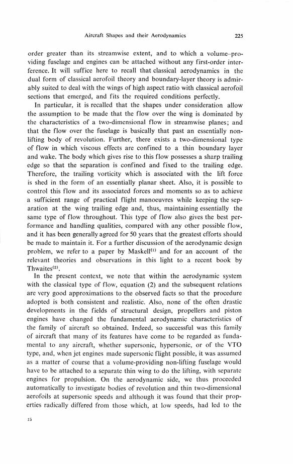
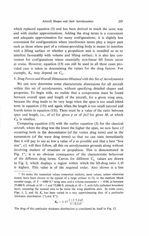
Comparing equation (15) with the earlier equation (3) for the classicalaircraft, where the drag was the lower the higher the span, we now have s,'Ioccurring both in the denominator (of the vortex drag term) and in thenumerators (of the wave drag terms) so that we can state immediatelythat it will pay to use as low a value of p as possible and that a best "boxsize", sd, will then follow, all this on aerodynamics grounds along withoutinvolving matters of structure or propulsion. This is demonstrated inFig. 1*; it is an obvious consequence of the characteristic behaviourof the different drag terms. Curves for different C, values are drawnin Fig. 2, which displays a region within which the lift-drag ratio LIDis highest. This value is of the required order. Also shown is a line
* To make the numerical values somewhat realistic, most values, unless otherwisestated, have been chosen to be typical of a large airliner to fly in the medium Machnumber range, of S = 6000 ft.' wing area and a volume parameter r = 0.04, at between35,000 ft. altitude at M — 1 and 75,000 ft. altitude at M = 5, with fully turbulent boundarylayer, assuming the wanted area to be twice the wing planform area. In some cases,Figs. 1, 2, and 14, IC, has been varied in a way approximating that of a particularthickness distribution ("Lord V"):
1 —1• 5 I.Ly/1K0 = 1. 17
1, 4
The drag of this particular thickness distribution is considered by itself in Fig. 12.

230 D. KOCHEMANN
CL along which the CL value is a given fraction of the value,
CL„„ at which the highest LID is reached for As = const.; as stated
earlier, one might cruise near this line, for non-aerodynamic reasons. Along such a line (C, = CL„,/I 2), LID reaches a maximum value for
a certain sll or fis/1, for a given value of T. Similarly, values of -r can be
0-025Co 0-1
0-020
0 • 015
CD
0-010
0 • 005
.. •LIFT VORTEX •••••
• THICKNESS- WAVE
FRICTION
0-2 0.4 0-6 s 0-8 1-0
A
FIG. 1. Typical drag coefficients at Af - - 2 p = 1/2 j = 0.04 A — 1 — I
S 6000 FT 2.
plotted along again along such lines, for required values of LID andthese curves show again maxima, i.e., thickest wings, for values of 511,which are very close to those obtained before.
The main conclusion to be drawn from these results is that the bestlift-drag ratios or thickest wings are obtained when 19.5,11 is well belowunity—near 0.35 in this case where M = 2, so that is near 0-2. Wethus obtain a "box size", into which the aircraft must fit. This varieswith Mach number, and typical values are = 0.4 for M = 1.2; = 0.2for M = 2; = 0-1 for M = 5. So the box becomes narrower as the design Mach number is increased. As the main geometric characteristic,
0
Aircraft Shapes and their Aerodynamics 231
this box size assumes for supersonic configurations the part played by theaspect ratio for the classical aircraft.
As a result of many similar calculations we find that the best box sizeis not very sensitive to the actual values of the other parameters and dragfactors, and that even drastic changes in the latter make very little differ-
0- 025
0-0 20
0-015
CD
Coo-15
evia
449'
cri•/
0005
0
9
0•20.4 0-6 9 0.8A Z
1•0
FIG. 2. Typical drag coefficients at Af = - 2 p = 1/2 fl = 0.04 K,, = K„, ---1 S = 6000 FT 2.
ence. Smaller values of the planform parameter p correspond to slightlywider boxes; better (i.e. smaller) values of Ko allow wider boxes; as dobetter values of K„, and worse values of IC, . Generally, worse (i.e. higher)values of Ko, K,„ and K eive lower LID for a given -r or restrict T to lowervalues for given L !D; whereas lower values of p improve matters. Further,if the wetted area is essentially mater than twice the planform area, thenLID is generally lower and best values occur at slightly higher values of
This general result is not substantially changed if configurations areconsidered where the length of the volume differs from that of the liftingsurface, assuming for the moment that such configurations could be realizedin practice. The extreme case of this kind is evidently obtained when onlythe last two terms in equation (15) are assumed to depend on s/I or, what is
232 D. KOCHEMANN
equivalent, when x is assumed to be zero. In that case dC,10(sll) = 0,
i.e., the drag is lowest and LID highest, when
R s // K,(16)
/ 2Kw
so that < 0-707 since in most cases K e K. A small but non-zero
thickness will bring the value of PsIl for the best LID well below 0.707.
We can, therefore, draw an important conclusion without knowing any
details of actual configurations, namely, that the box size into which anaerodynamically efficient supersonic aircraft must fit is always less wide
than long and that the box becomes the narrower the higher the Mach
number. As a rough guide,
sIl lies between 0.3 and 0.4 and t3s,'Iis about 0.2 at M = 1.2;
lies between 0.15 and 0.25 and tisll is about 0.35 at M = 2;
lies between 0.05 and 0.15 and usll is about 0.5 at M = 5.
This means that the aircraft, whatever its detail shape, should always lie
well within the Mach cone from its nose.
This result corresponds to that obtained earlier: that the classical air-craft normally has wings of moderate or large aspect ratio; and in the
same way as that allowed us to restrict ourselves to what we call classical
aerodynamics, we shall now attempt to use this new result to select such
shapes which appear promising and cultivate their aerodynamics, and to
leave others out altogether. At the same time, we shall try to follow the
classical example in directing our attention towards the aerodynamics of
such flomrs which physically exist and which are acceptable for engineering
purposes. With this approach we differ from much of past practice in
supersonic aerodynamics and design in two main respects: As a rule,
thickness and lift effects have been treated and "optimized" separately;
all too often, "optimum" layouts have been devised on the basis of theo-
retical flow s to which nothing corresponded in nature.* When, as a result,
the actual flows were "lousy", some of us resigned ourselves to this
as an apparently unavoidable state of affairs and so a long string of
patent-cures-in-a-small-way has appeared over the last 10 or 15 years.
6. Some Possible Solutions
Our next task is to fill with realistic aircraft shapes the boxes previously
determined. Some of these are shown in Fig. 3, with some slight adjust-
ments depending on the particular configuration used in anticipation
of later results. As will be seen, we propose to deal with a swept wing-
* A typical example of this was given in Fig. 7 of R. T. Jones paper") at the lastCongress.

Aircraft Shapes and their Aerodynamics 233
fuselage combination, with a slender wing, and with a yawed wing as
suggested 20 years ago by E. von Ho1st and taken up again by R. T. Jones")at the first Congress of this Council.
r - --, — --1.
i , . I ir — —;
k -
-- .4 1 ..,' 1.7i, .1
‘ i .1.. - --I 557)1 I
I I II I II I II I I
68° I
. I.
1
IIIIII
k os ko.3 49 F0.35 =0-Z *03 f=047
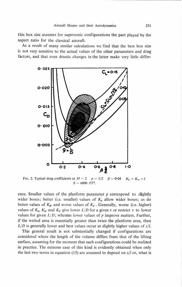
/31=0.4 1.20 •23 M = 2Flo. 3. Some typical aircraft shapes.
We do not propose to deal with a number of other layouts. Near-rec-tangular thin wings on a discrete fuselage are left out because their neces-
sarily short lifting length must lead to high values of at least Kw so that
their performance is altogether too poor, if the fuselage is non-lifting.
If a fuselage with usually near-circular cross-sections is meant to lift,
it must be ruled out as unsuitable for engineering applications because
it is known that the separation lines cannot then be fixed so that the flow
=0• at =0.6w
=025 U-038
M = 1.2
At=0-25 i=oas
234 D. Ki.:ICHEMANN
is essentially unsteady and liable to lead to asymmetries and the sheddingof free vortices. Further, the flow over wing and fuselage is bound tochange radically throughout the flight range. Similar reasons can be ad-vanced against the use of other combinations of fuselages and thin wingswith supersonic leading and/or trailing edges, such as some wings withplanforms of delta, lozenge, or arrowhead shape. In some cases, flow
14
70°yt =75
12 -[
I r1 1
Ia.
ilo 1
b/ IL / '
1. 1
/- :5 I i
i
II /
•
. I8 I
1
I-
2 s
6
4
= a8 6
12
CIRCLE(-o.b
)
2
00-2 0.4 0.6 /S 0-8
0.1 0-2 0.3 0.4 0.5Ste
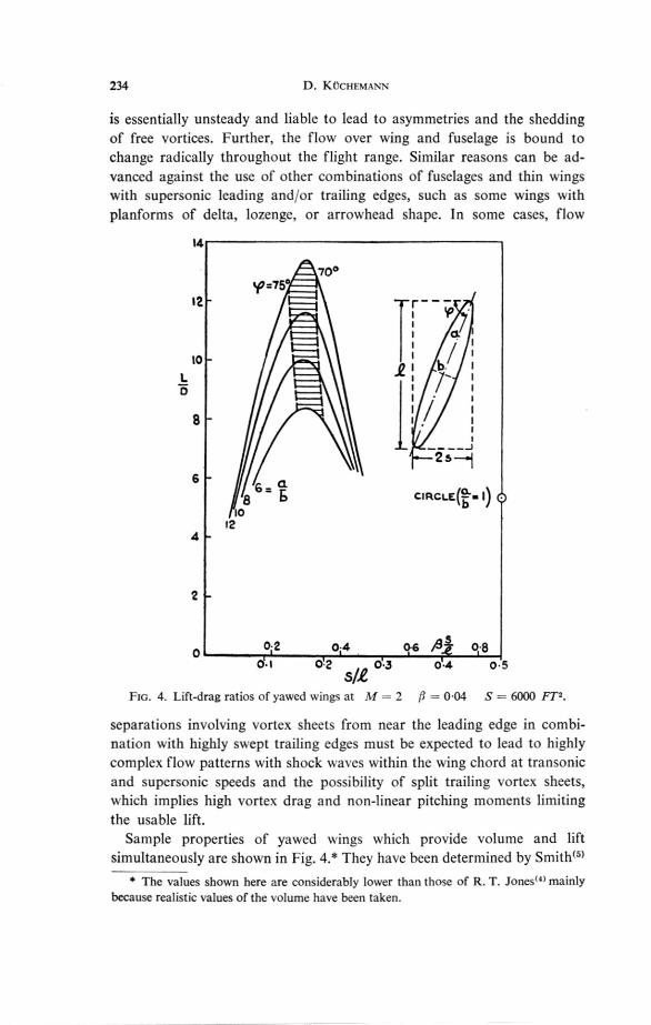
FIG. 4. Lift-drag ratios of yawed wings at M — 2 /3 — 0.04 S = 6000 FT, .
separations involving vortex sheets from near the leading edge in combi-nation with highly swept trailing edges must be expected to lead to highlycomplex flow patterns with shock waves within the wing chord at transonicand supersonic speeds and the possibility of split trailing vortex sheets,which implies high vortex drag and non-linear pitching moments limitingthe usable lift.
Sample properties of yawed wings which provide volume and liftsimultaneously are shown in Fig. 4• * They have been determined by Smith(51
* The values shown here are considerably lower than those of R. T. Jones") mainlybecause realistic values of the volume have been taken.
Aircraft Shapes and their Aerodynamics 235
who extended earlier theories to cover thick wings. We find that the generallevel of LID is of the order required from earlier performance considera-tions. We also find that the angle of yaw should lie within a fairly narrowband for best efficiency. The lift-drag ratio falls steeply if the angle of yaw istoo high and the enclosing box too narrow (q- = 90° where the curves endon the left-hand side), and again if the angle of sweep is too low and thebox too wide (the mean spanwise direction is sonic where the curves endon the right-hand side). So this particular example confirms the earliergeneral statement that wings should lie well within the Mach cone from
900
tic 0.1CI.= 0 3
COS 0.20.1
so°
0.6
3 0.7
0 0 • 5 1.0 1• 5 2.0 2-5
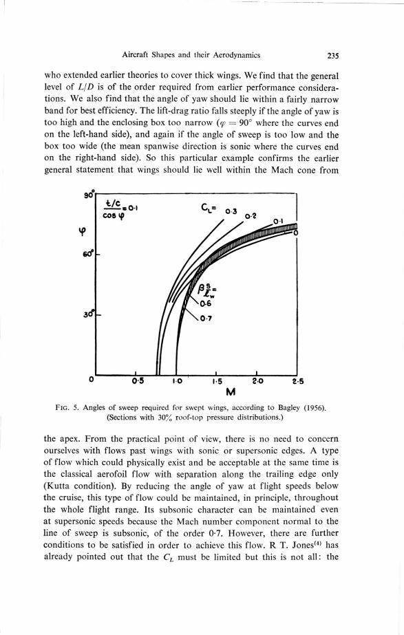
FIG. 5. Angles of sweep required for swept NA.ings, according to Bagley (1956). (Sections with 30% roof-top pressure distributions.)
the apex. From the practical point of view, there is no need to concernourselves with flows past wings with sonic or supersonic edges. A typeof flow which could physically exist and be acceptable at the same time isthe classical aerofoil flow with separation along the trailing edge only(Kutta condition). By reducing the angle of yaw at flight speeds belowthe cruise, this type of flow could be maintained, in principle, throughoutthe whole flight range. Its subsonic character can be maintained evenat supersonic speeds because the Mach number component normal to theline of sweep is subsonic, of the order 0.7. However, there are furtherconditions to be satisfied in order to achieve this flow. R T. Jones") hasalready pointed out that the CL must be limited but this is not all: the
236 D. KCCHEMANN
thickness of the wing and the details of the pressure distribution alone
the surface come into it, too. Bagley's work(61 is relevant here and we
quote one of his results for wings of infinite span in Fig. 5, showing values
of tic, 9, CI, and M which, in the right combination, can keep the flow
just subcritical and of the classical type.
There are a great many other, as yet unsolved, difficulties to be over-
come in order to maintain this type of flow, and failure to solve thesewould make results such as those in Fig. 4 meaningless and the whole
scheme unacceptable in practice. Some are related to the design of theends of the wing where the full sweep of the isobars must be maintained.
Others are concerned with the stability and control of such wings and,
by no means least of all, the economic utilization of the volume inside
the wing for the purpose of accommodating passengers and other loads
will present an exceedingly difficult task. At present, therefore, the yawed-
wing aircraft would appear to be a very instructive example but not a really
practical proposition.
A much more promising picture emerges when considering swept wing-
fuselage combinations. This is the one case so far where it is reasonable
to make a distinction between the length, 1, of the volume-providing body
or fuselage and the lifting length, /, of the wing: In the first place, the
fuselage can be so designed as to carry no load except in the region of the
wing; secondly, we know") that the thickness of the wing and fuselage
together can be so designed, mainly by fuselage shaping, that the wave
drag due to volume is, to a first order, that of the original fuselage alone.
There is then in effect no wave drag which depends on the volume con-
tained in the wing and on its shape.
Some typical results* are shown in Fig. 6. The drag factors chosen are:
= I. because one would attempt to approach this value of the best
body of revolution of the given length and overall volume; and Kv = = 1, because one would hope to find wing shapes with nearly elliptic
loading both spanwise and lengthwise. The planform shape parameter,
now refers to the planform of the wing along its surrounding box,
and one would attempt to find shapes with p„- < ',I,. The results in FiR. 6
are twain of the order required from earlier performance considerations.
They also confirm that the most efficient configurations lie well within
the Mach cone from the nose, and the overall box size is again much the
same as stated above. In addition, we find that the wing itself is also sub-
sonic: There would seem to be no point in going to a sonic leading edge,
* To make the results roughly comparable with those for the other layouts, a fuselageof 180 ft length has been chosen with an overall volume parameter T = 0.06; and a wingarea of 3600 ft2. CDF = 0.036 instead of about 0.003 because of the relatively largerwetted area.

Aircraft Shapes and their Aerodynamics 237
say. (We may mention here that, for a sonic or supersonic leading edge,
the values of the drag factors assumed are too good so that the actual
D-values must be expected to be lower than those shown.) Near the
maximum values of LID, the Mach number component normal to the
line of sweep is again around 0-7 and thus the classical aerofoil flow again
offers itself as one which is both consistent with the assumption made
in arriving at these results and also usable in engineering practice.
12
10
k , 1, 1
I IIt
0-2 0-4 0-6 0-80
-1 0-2 0-3 0-4 0-5
FIG. 6. Lift-drag ratios of swept wing-body combinations AI = 2 ;I 0.06
Cdf = 0.006 S — 3600 FT 2 Ko — 1 K„.i„o - - I.
Having stipulated the general layout and the type of flow, the design
aims are clear. The planform shape; camber and thickness distribution of
the basic section which must again conform to Bagley's criterion, Fig. 5;and further, the spanwise variations of thickness, camber and twist; the
shapes of the upper and lower wing-fuselage junctions; and the shapes
of the fuselage cross-sections and of its own camber line can all be used
to this end. The development of the three-dimensional boundary layer
and the occurrence of shock waves on the wing appear to be the main
4
2
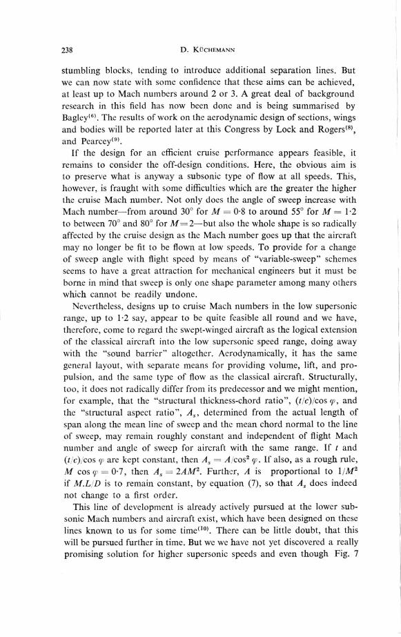
238 D. KYCHEMANN
stumbling blocks, tending to introduce additional separation lines. Butwe can now state with some confidence that these aims can be achieved,at least up to Mach numbers around 2 or 3. A great deal of backgroundresearch in this field has now been done and is being summarised byBagley"). The results of work on the aerodynamic design of sections, wingsand bodies will be reported later at this Congress by Lock and Rogerso),and Pearcey").
If the design for an efficient cruisc performance appears feasible, itremains to consider the off-design conditions. Here, the obvious aim isto preserve what is anyway a subsonic type of flow at all speeds. This,however, is fraught with some difficulties which are the greater the higherthe cruise Mach number. Not only does the angle of sweep increase withMach number—from around 30° for M = 0.8 to around 55° for M = 1.2to between 70° and 80° for M= 2—but also the whole shape is so radicallyaffected by the cruise design as the Mach number goes up that the aircraftmay no longer be fit to be flown at low speeds. To provide for a changeof sweep angle with flight speed by means of "variable-sweep" schemesseems to have a great attraction for mechanical engineers but it must beborne in mind that sweep is only one shape parameter among many otherswhich cannot be readily undone.
Nevertheless, designs up to cruise Mach numbers in the low supersonicrange, up to 1.2 say, appear to be quite feasible all round and we have,therefore, come to regard the swept-winged aircraft as the logical extensionof the classical aircraft into the low suNrsonic speed range, doing awaywith the "sound barrier" altogether. Aerodynamically, it has the samegeneral layout, with separate means for providing volume, lift, and pro-pulsion, and the sante type of flow as the classical aircraft. Structurally,too, it does not radically differ from its predecessor and we might mention,for example, that the "structural thickness-chord ratio", (rc),cos cp, andthe "structural aspect ratio", As, determined from the actual length ofspan along the mean line of sweep and the mean chord normal to the lineof sweep, may remain roughly constant and independent of flight Machnumber and angle of sweep for aircraft with the same range. If t and(t c) cos 9 are kept constant, then As= A cos2 9,. If also, as a rough rule,M cos q = OE7, then As= 2AM2. Further, A is proportional to 1/M2if MI. D is to remain constant, by equation (7), so that As does indeednot change to a first order.
This line of development is already actively pursued at the lower sub-sonic Mach numbers and aircraft exist, which have been designed on theselines known to us for some time('°). There can be little doubt, that thiswill be pursued further in time. But we we have not yet discovered a reallypromising solution for higher supersonic speeds and even though Fig. 7
Aircraft Shapes and their Aerodynamics 239
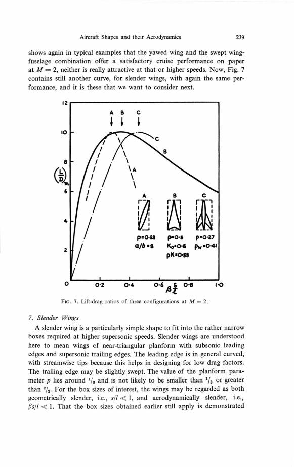
shows again in typical examples that the yawed wing and the swept wing-fuselage combination offer a satisfactory cruise performance on paperat M = 2, neither is really attractive at that or higher speeds. Now, Fig. 7contains still another curve, for slender wings, with again the same per-formance, and it is these that we want to consider next.
12
A B C
10
// \ 8
8 / \
(i )
// / \A
/ \6 / /
rA
rB-1
rC
- 1./ 1 i 1 1 1
14 / I
--J
I-
I)2043 p.o.s pso.v
2 / a/b .13 Kos04 pw 604 1piCa0-56
0 02 0•4 0.6 S 0 •8 1.0AZ
FIG. 7. Lift-drag ratios of three configurations at M = 2.
7. Slender Wings
A slender wing is a particularly simple shape to fit into the rather narrowboxes required at higher supersonic speeds. Slender wings are understoodhere to mean wings of near-triangular planform with subsonic leadingedges and supersonic trailing edges. The leading edge is in general curved,with streamwise tips because this helps in designing for low drag factors.
The trailing edge may be slightly swept. The value of the planform para-meter p lies around V, and is not likely to be smaller than 1/3 or greaterthan 2/3. For the box sizes of interest, the wings may be regarded as bothgeometrically slender, i.e., sI I 1 , and aerodynamically slender, i.e.,gsll < 1. That the box sizes obtained earlier still apply is demonstrated
240 D. KUCHEMANN
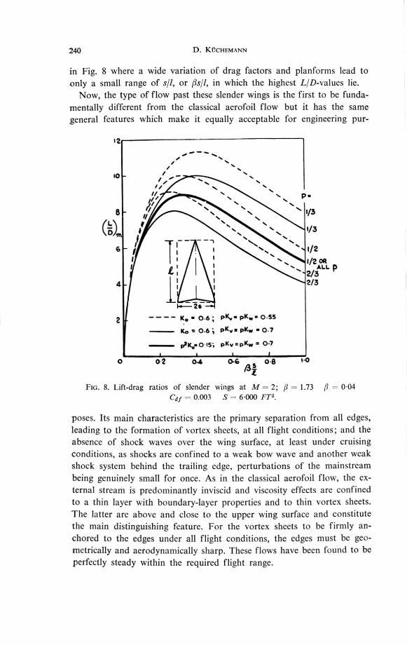
in Fig. 8 where a wide variation of drag factors and planforms lead toonly a small range of or 16s1l, in which the highest L/D-values lie.
Now, the type of flow past these slender wings is the first to be funda-
mentally different from the classical aerofoil flow but it has the samegeneral features which make it equally acceptable for engineering pur-
12
10 / '...
/„.""— ......
--.. --..I, ----- s..
I/ — --.. ...... P./ /
/. ---
-....--.. ....
....
8 / ---.. ........
%.i/
(1715) :
N.a a.
5. -
a.*.
*a.i/3
il r — -, ."...
.
., 7, , ...•... 112 OR
6 f i i ••• . 1/2
./. :1
1.. .....- v3ALLI
ill 1
12/34
2 — — — — K. 0.6 ; pIÇ.pK .. 0.55
Ko = 0.6 ; PKv. PKw • 0.7
p2K.=0 15; PKv =0(.4 = 0.7
0 2 0-4 0-6 0-8 t.0
FIG. 8. Lift-drag ratios of slender wings at M — 2; ,8 = 1.73 fl 0.04
Caf = 0.003 S = 6-000 FT2 .
poses. Its main characteristics are the primary separation from all edges,leading to the formation of vortex sheets, at all flight conditions; and theabsence of shock waves over the wing surface, at least under cruisingconditions, as shocks are confined to a weak bow wave and another weakshock system behind the trailing edge, perturbations of the mainstream
being genuinely small for once. As in the classical aerofoil flow, the ex-ternal stream is predominantly inviscid and viscosity effects are confinedto a thin layer with boundary-layer properties and to thin vortex sheets.The latter are above and close to the upper wing surface and constitutethe main distinguishing feature. For the vortex sheets to be firmly an-
chored to the edges under all flight conditions, the edges must be geo-metrically and aerodynamically sharp. These flows have been found to beperfectly steady within the required flight range.
Aircraft Shapes and their Aerodynamics 241
The main features of this flow have been first described by Roy(") andMaske1102) and Maskell and Weber"3) have considered it and the aero-dynamic design principles involved in some detail. This type of flow mustneces2,arily include one condition (i.e. one value of CI and M), underwhich the leading edges are attachment lines. Above or below this Ccvalue,the vortex sheets lie either wholly above or wholly below the wing. Thisoccurs at CL = 0 with symmetrical wines and at CL 0 with cambered,or warped, wings. To achieve this attachment at one CL is one of theimportant design conditions. The flow then happens to be the same asthat assumed in supersonic linearized theory, with trailing-edge separationonly and a near-planar trailing vortex sheet. This appears to be one ofthe few cases in which this otherwise hypothetical flow has a real counter-part in nature. Thus a considerable body of theoretical work becomesavailable for the purpose of designing slender wings, notably the workof Ward and Lighthill (11,16),Weber"5) and R. T. Jones"), Lord andBrebneruu) and others.
Some indication of the cruise performance of these w ings is gi% en inFig. 8. The dashed lines are based on the assumption that the factor Ko
into the zero-lift wave drag can always be kept below unity, thus makinguse of Lighthill's theoretical prediction("). For simplicity of presentation thelift-dependent drag factors are taken to be equal and to have a value whichmust be considered as rather good (Kr = K, =1-1 for p = 1/2). Good valuesof L'D, amply sufficient for lona-range aircraft, are then achieN edwith wings in the whole p-range, although there remains an incentiveto use wings with a low value of p. The full lines are based on the sameassumption for K, but on less favourable assumptions for the lift-dependentdrag, typical for wings where the camber is not very effective. Obviously,an efficient camber is worth striving for. Lastly, the thick line is obtainedif K, is assumed to vary with p in such a way that it increases as p de-creases, as an indication of increasing difficulties in the design. In thiscase, the distinction between wings of different p-values disappears andwings with lower p-values no longer offer an advantage. But even inthis case, the performance is acceptable for long-range aircraft. With thispotential performance, together with a perfectly usable type of flow, thereis hardly any incentive left to try to make yawed or swept wings workat higher Mach numbers, as they do not offer a better performance. Thereis no incentive to use current conventional layouts, as their performanceis certainly inferior.
There is unfortunately no time left to discuss the important and interestinglow-speed aspects of slender wings in any detail (see e.g. Thwaites")).The main feature is, of course, that the coiled vortex sheets abovethe w ing produce a non-linear lift force which may be considerably greater
Is

242 D. KIDCHEMANN
than the linear lift obtained on wings with trailing edge separation only.In practice, this non-linear lift makes a good take-off performance andlow approach speeds possible, in spite of the low aspect ratio these wingshave. How much the non-linear lift matters may be demonstrated byassuming the lift to be of the approximate form
C"I = Aa+2a2 = cr a+2a22 (17)
and determining the wing area needed to sustain a given overall weight L at a given dynamic head q and angle of incidence a. This comes out as
lq 1S =
L (18)
2a sll a
2p — :7T
where the term
Llqcc=
2aa
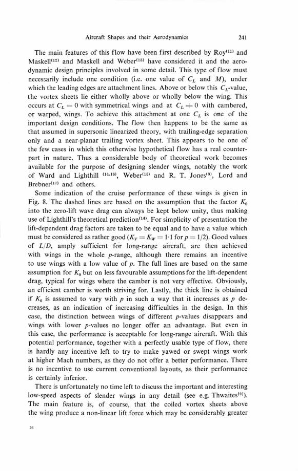
is the area needed with an unswept wing of infinite span. Values of S1S,,are shown in Fig. 9, where the upper curve indicates the increase in wingarea, which is necessary if sll is reduced in the case of linear lift only,whereas the lower curve includes the non-linear lift obtainable at a =as an example. However, this curve still rises as all is decreased or thedesign Mach number increased, but it must be borne in mind that someincrease in wing area, or decrease in wing loading, will be needed anywaybecause the faster aircraft will also fly higher. Since, further, the decreasein sill Nsith M may well be less than indicated in Fig. 8, there is no unduediscrepancy between low-speed and cruise performances on this countalone. There are, however, other problems, notably in the field of flightdynamics, which we have no time to discuss here.
We turn now to a brief discussion of some of the aerodynamic problemswhich are typical of slender wings. The shedding of vorticity from sideedges presents a new kind of problem altogether. Early work in this fieldis discussed by Thwaites(2), and Maskell"8) has established similaritylaws for the initial rate of shedding of vorticity for conical bodies as itdepends on the angles of incidence and sweep, on the edge angle and itsdroop, and on the cross-sectional shape. The first of these—that similarflow s are obtained when al(s1l) is the same—is already well-known. Ob-servations of non-conical flow patterns, including some which lead toan asymmetric shedding of vorticity, have been described by Maltby(19).The results of this work have a bearing on a variety of aspects: on flightdynamics, on forces and moments, and also on vortex drag. We note,
(19)
Aircraft Shapes and their Aerodynamics 243
for example, that K, = 1 can no longer be regarded as a lower bound,as it relates to the minimum vortex drag for wings of given overall liftand span, which leave a plane sheet of trailing vortices behind them,whereas the shape of the sheet behind slender wings is essentially non-planar.
0
a p 4
St& —
FROM NON— LINEAR LIFT.
00a
M= 54 3 2 FOR Ern 0.3.5
0'1 0.2 0.3 0.4 0.5 0.6Sit
Flo. 9. Wing areas required for low-speed performance. P - 1/2. a : R. T. Jones lift, b: with non-linear lift at a — ;00. c: including practical allowance.
Another set of problems is concerned with the development of theboundary layer which is essentially three-dimensional. New methods forcalculating these must be devised, and the present state of our knowledgehas been summarized by Cooke and Hall(20). Further, new criteria mustbe found to define what constitutes pressure fields which are either favour-able or unfavourable to separation occurring somewhere on the surface,apart from the separation from the edges. Such secondary separationsare obviously undesirable. The relevant criteria have been established byMaskel and Weber(13).
Further problems arise when considering the wave drag at zero liftfor thick wings. Lighthill's prediction" that the wave drag can be reducedbelow that of the corresponding body of revolution by spreading the volume
6
"ke
4
0
16.

244 D. KUCHEMANN
spanwise has been followed up and typical results, by Weber"6 ), are shownin Fig. 10. Depending on the slope and the curvature at the trailing edgeof a family of area distributions, the drag factor Ko is found to be boundedbelow by an envelope. Then tw o further problems arise: Firstly, the re-liability of such results, as some of the shapes implied may cease to be
SIM n=1-2
2 468
1-0
0-8
-
_ ••••• •• • as.
• •
ENVELOPE FOR
DELTA WINGS WITH
04 RHOMBIC CROSS-SECT.
KoTHIN-WING THEORY
0-4
ENVELOPE
0-2
0-4
0-100 -50 0 +50 s110)+100 +150
v/e3
FIG. 10. Zero-lift wave drag according to slender wing theory for a family of sNings.3S(.0
— (1 — X) Y2 y x", k = 1.85.0
slender and smooth, and as different theories may give different numericalanswers. Secondly, the question of how low the drag factor can be de-signed to be, as numerical results depend on the particular family of shapeschosen. Thus optimization procedures appear in a new light and someof these, such as some popular "area rules", become suspect.
Similar problems occur with regard to the wave drag due to lift and,as an illustration, Fig. 11 shows some results from an extension of Adams

Aircraft Shapes and their Aerodynamics 245
and Sears(21) not-so-slender wing theory, due to Weber, for the drag factorKw for a family L(x) of loadings along the chord of the wing, which havedifferent values of the load L(1) at the trailing edge and different positionsx of the centre of pressure. Again, the curves are bounded below byC. Q.
an envelope and some of the values of K1, along this envelope are well
1.6
L (1).o
1.4 1
2
0
0-8
0 6 ENvELOPE
o 4
4
/0-4
1:
o0-40 0-4.5 0-50 0 55 0.60 3c. 0-65 0-70
c. P.
FIG. 11. Lift-dependent wave drag according to not-so-slender wing theory for a family of wings.
below R. T. Jones") "lower bound". This kind of result has some bearingnot only on the drag itself but also on the trim problem. Evidently, fore-planes which invariably introduce a trim-drag penalty and considerablecomplications in the flow pattern and flight behaviour are no longerneeded with properly designed slender wings.
To end this discussion of slender wings, we might look at some of theexperimental results obtained. Fig. 12 gives measured values of the
246 D. KÜCHFMANN
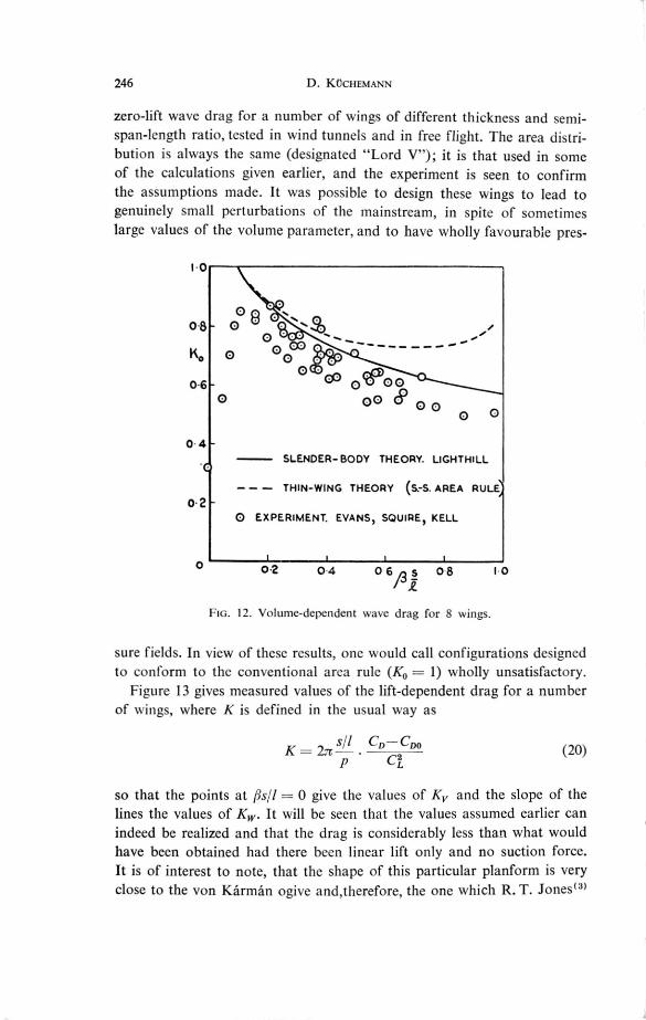
zero-lift wave drag for a number of wings of different thickness and semi-span-length ratio, tested in wind tunnels and in free flight. The area distri-bution is always the same (designated "Lord V"); it is that used in someof the calculations given earlier, and the experiment is seen to confirmthe assumptions made. It was possible to design these wings to lead togenuinely small perturbations of the mainstream, in spite of sometimeslarge values of the volume parameter, and to have wholly favourable pres-
1.0
. •
0 00-8 0 Q
0
0
0-6 0 sec)0o 00 6) 0 0
0 4SLENDER-BODY THEORY. LIGHTHILL
— — — THIN-WING THEORY (S.-S. AREA RULE
0.20 EXPERIMENT. EVANS, SQUIRE, KELL
O 0 •2 04 0 6 A s 0 8 1 0
FIG. 12. Volume-dependent wave drag for 8 wings.
sure fields. In view of these results, one would call configurations designed to conform to the conventional area rule (K,= 1) wholly unsatisfactory.
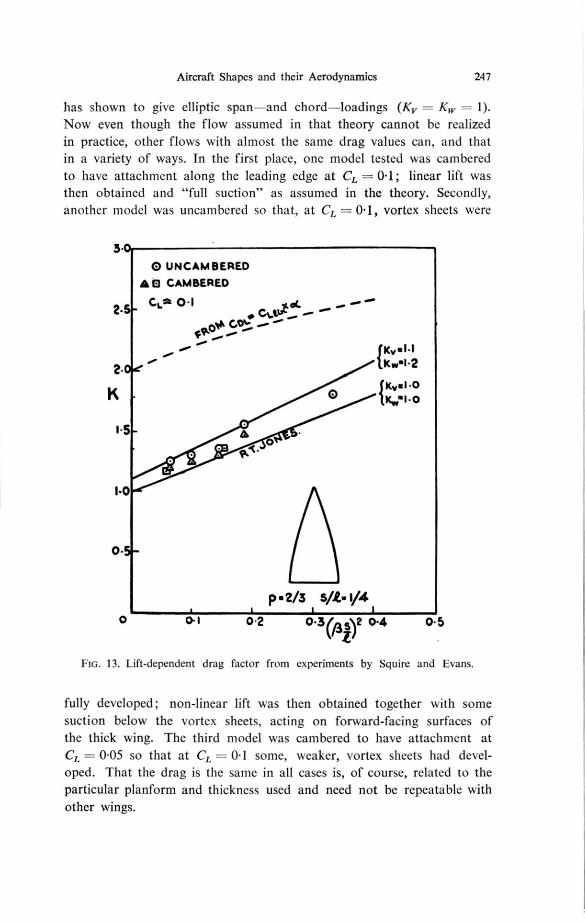
Figure 13 gives measured values of the lift-dependent drag for a numberof wings, where K is defined in the usual way as
sll CD—CmK = 27 .
C2(20)
so that the points at fisll = 0 give the values of Kv and the slope of thelines the values of K. It will be seen that the values assumed earlier canindeed be realized and that the drag is considerably less than what wouldhave been obtained had there been linear lift only and no suction force.It is of interest to note, that the shape of this particular planform is veryclose to the von Kármán ogive and,therefore, the one which R. T. Jones")
O
Aircraft Shapes and their Aerodynamics 247
has shown to give elliptic span—and chord—loadings (K = K, — 1).
Now even though the flow assumed in that theory cannot be realizedin practice, other flows with almost the same drag values can, and thatin a variety of ways. In the first place, one model tested was camberedto have attachment along the leading edge at CI = 0.1; linear lift wasthen obtained and "full suction" as assumed in the theory. Secondly,another model was uncambered so that, at CL = 0.1, vortex sheets were
3.
O UNCAMBERED
A 0 CAMBERED
CI.* 0.1 ••••• "*.• eutut
'NO*
fKv•I-11.Kw.1.2
{Kval.00 Kwal.0
1.5
2.
2.
1.0
0.
p • vs sft. 1/40 0.1 0.2 0-3 (p5 )2 0 •4 0.5
FIG. 13. Lift-dependent drag factor from experiments by Squire and Evans.
fully developed; non-linear lift was then obtained together with somesuction below the vortex sheets, acting on forward-facing surfaces ofthe thick wing. The third model was cambered to have attachment atCL = OE05 so that at CL = 0.1 some, weaker, vortex sheets had devel-oped. That the drag is the same in all cases is, of course, related to theparticular planform and thickness used and need not be repeatable withother wings.
248 D. KCCHEMANN
8. Conclusions
In conclusion, we may say that it has been shown to be worthwhile
to bear in mind the practical application at an early stage. If the task
is the simplest, namely, to achieve a given range, then even the crudest
knowledge of the structural, propulsive, and aerodynamic components
of an aircraft is sufficient to define some overall dimension into which
the aircraft must fit. We have seen that, in the case of the classical aircraft,
this leads to the conclusion that we need to concern ourselves only with
wings of moderate or large aspect ratios. In the case of supersonic flight,
with different means of propulsion and a new set of aerodynamics, this
leads to the definition of box sizes with certain relations between span
0-5
0-4
0-3
L/D = 100-2
0.1
0i.01•5
9
9
2.0
8
8
8
2.5
•
3-0
cvb-e
L10=.9
3-5 4.0
_
4.5
0.04
0.05
0-06
0-07
0.07 0.04
5-0
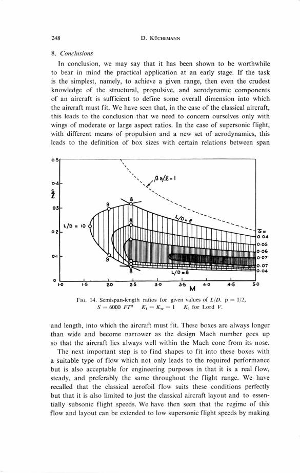
Flo. 14. Semispan-length ratios for gken values of 171). p 1 1,S 6000 FT' K, K, —1 K., for Lord V.
and length, into which the aircraft must fit. These boxes are always longer
than wide and become nartower as the design Mach number goes up
so that the aircraft lies always well within the Mach cone from its nose.
The next important step is to find shapes to fit into these boxes with
a suitable type of flow which not only leads to the required performance
but is also acceptable for engineering purposes in that it is a real flow,
steady, and preferably the same throughout the flight range. We have
recalled that the classical aerofoil flow suits these conditions perfectly
but that it is also limited to just the classical aircraft layout and to essen-
tially subsonic flight speeds. We have then seen that the regime of this
flow and layout can be extended to low supersonic flight speeds by making

Aircraft Shapes and their Aerodynamics 249
use of sweep. And, finally, we have discussed an entirely new type of flow,
that past slender wings, and shown that this leads to a natural solution
for supersonic aircraft.
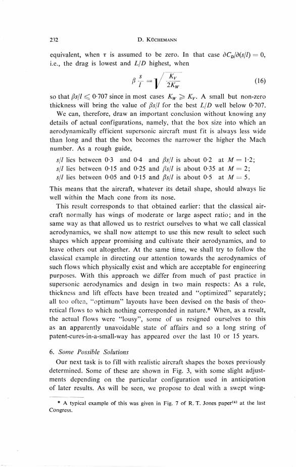
As we have been mainly concerned with examples at lower supersonic
speeds and at Mach numbers around 2, we would end with a last Fig. 14,
which gives box sizes and expected aerodynamic performances for slender-
wing layouts up to higher Mach numbers. Lines along which LID8 for r = 0.04 are closed at the lower end by a curve along which L'D
varies in a manner which is typically needed to balance the loss of pro-
pulsive efficiency of turbojet engines as the Mach number decreases.
Within this band lie all the wings which give a better performance or
allow a greater volume. Such a diagram gives not a few pointers to future
developments and makes it clear at the same time that the aerodynamic
design of supersonic aircraft is, as always, as much a matter of low-speed
aerodynamics as of high-speed aerodynamics. But whereas we can see
real aircraft emerge now at the lower Mach numbers, the higher speeds
will demand not only the integration of volume and lifting surface but
also of propulsion. We also realize that research into fluid dynamics and
chemical kinetics must go together with that into structures, materials
and systems. There can be little doubt, however, that human flight will
in time far exceed its present limitations.
REFERENCES
MASKELL, E. C., Aerod). namic Design. Progress in Aeronautical Sciences, vol. 1.
Pergamon Press
THWAITES, B. (Editor), Incompressible Aerodynamics. Fluid Motion Memoirs.Oxford, 1960
JONES, R. T., The minimum drag of thin wings in frictionless flow. J. Aero. Sci.,
vol. 18, p. 75, Febr. 1951
JONES, R. T., Aerodynamic design for supersonic speeds. Advances in Aeronautical
Sciences. Proceedings of the First International Congress in the Aeronautical Scien-
ces. Madrid Sept. 1958, vol. 1, p.34. Pergamon Press, 1959
SMITH, J. H. B., The wave drag of thick yawed wings. Unpublished M.O.A. Report
1960
BAGLEY, J. A., The aerodynamic design of swept wings. To be published in vol. 2
of Progress in Aeronautical Sciences. Pergamon Press
KÜCHEMANN, D., Methods of reducing the transonic drag of sweptback wings
at zero lift. J. Roy. Aero. Sci., vol. 61, p.37, Jan. 1957
Loci:, R. C. and ROGERS, E. W. E., Aerodynamic design of swept wings and bodies
for transonic speeds. Proceedings of the Second International Congress in the
Aeronautical Sciences. Zürich, 1960. To be published
PEARCEY, H. H., The design:of wing sections for swept wings at transonic and super-
sonic speeds. Proceedings of the Second International Congress in the Aeronautical
Sciences. Zürich, 1960. To be published
250 D. KUCHEMANN
KCCHEMANN, D. and WEBER, J., The subsonic flow past swept w ngs at zero
lift without and with body. R. and M, 2908, March 1956
Roy, M., Caractères de l'écoulement autour d'une aile en flèches accentuées.
C.R. Acad. Sci. Paris, vol. 26, p.I59, 1952
MASKELL, E. C., Flow separation in three dimensions. Unpublished M.O.A. Report,1951
MASKELL, E. C. and WEBER., J. On the aerodynamic design of slender wings.J. Roy. Aero. Soc., vol. 63, p.709, Dec. 1959
LIGHTHILL, M. J., The wave drag at zero-lift of slender delta w.ings and similarconfigurations. J. Fluid. Mech., vol. 1, p.337, Sept. 1956
LIGHTHILL, M. J., Mathematics and Aeronautics. 48th Wilbur Wright MemorialLecture, May 1960. To be published in J. Roy. Aero. Soc.
WEBER, J., Some notes on the zero-lift wave drag of slender wings with unswept
trailing edge. Unpublished. M.O.A. Report, Dec. 1959
LORD, W. T. and BREBNIR, G. G., Supersonic flow past slender pointed N4 ings
with "similar" cross sections at zero lift. Aeronaut. Quart., vol. 10, p. 79,
Feb. 1959
MASKELL, E. C., Similarity laws governing the initial growth of leading-edge vortexsheets in conical flow past sharp-edged slender bodies. Proc. of X. Int. Congressof Appl. Mechs. Stresa, Sept. 1960
MALTBY,R.L. The behaviour of coiled vortex sheets arising from two closelyspaced edge separations. Proc. of X. Int. Congress of Appl. Mechs. Stresa, Sept. 1960
COOKE,J. C. and HALL., M. G. Boundary layers in three dimensions. UnpublishedM.O.A. Report, Febr. 1960. To be published in vol. 2 of Progress in Aeronautical
Sciences. Pergamon PressMACADAMS, C. and SEARS, W. R., Slender-body theory. Review and extension.J. Aero. Sci., vol. 20, p.85, 1953
DISCUSSION
G. H. LEE: Dr. Küchemann has referred to the possibilities of the yawed aerofoilas a configuration for supersonic flight. My Company has given some considerationto this idea recently and I would like to present to you, briefly, some of the results wehave obtained, for I think that an International Conference such as this is a suitableoccasion for discussing new aircraft concepts, even though, as in this case, the ideamay seem bizarre at first sight; it was, after all, at the first I.C.A.S. in Madrid thatR. T. Jones introduced the yawed wing idea to many of us for the first time.
As we see it, the yawed wing aeroplane consists of a wing large enough to containthe passengers within the basic aerofoil contour; this means that it must be a fairlylarge aeroplane, probably at least 300 ft. from tip to tip. The crew v,ould be housedin a nacelle (or small fuselage) at the forward tip and there would be a fin at the rear-ward tip to give directional stability. Control would be obtained by means of "ailerons"(capable of moving symmetrically or anti-symmetrically as required) and a rudder.The engines would be mounted near the centre of the trailing edge.
The yawed wing is not only an efficient aeroplane when cruising supersonically,but should be thought of as the ideal solution to the problem of variable geometrysince the angle of yaw can be changed in flight, the main loads being supported ona perfect "air bearing" with only secondary loads having to be taken through mechanicalbearings; for to change the angle of yaw, it will be necessary only to change the angleof the fin, to rotate the crew cabin and to alter the angle of the jet issuing from the
Aircraft Shapes and their Aerodynamics 251
engines by means of some sort of adjustable propelling nozzle. This should be comparedwith "conventional" variable geometry aeroplanes in which major loads have to betaken through mechanical joints, with consequent problems of design, extra weight,and maintenance. The yawed wing indeed poses some aerodynamic problems, but oncethese have been overcome, the solution is permanent; the air does not need maintenance.
M 0
L /D
14
13
12
Il
10
9
\4 131—ss, •- HANDLEY P E
3" \I , ••eZ" \
'•
R.A.E.
\•
V
t.
765° 700 750
ANGLE OF YAW0
Flo. Al.
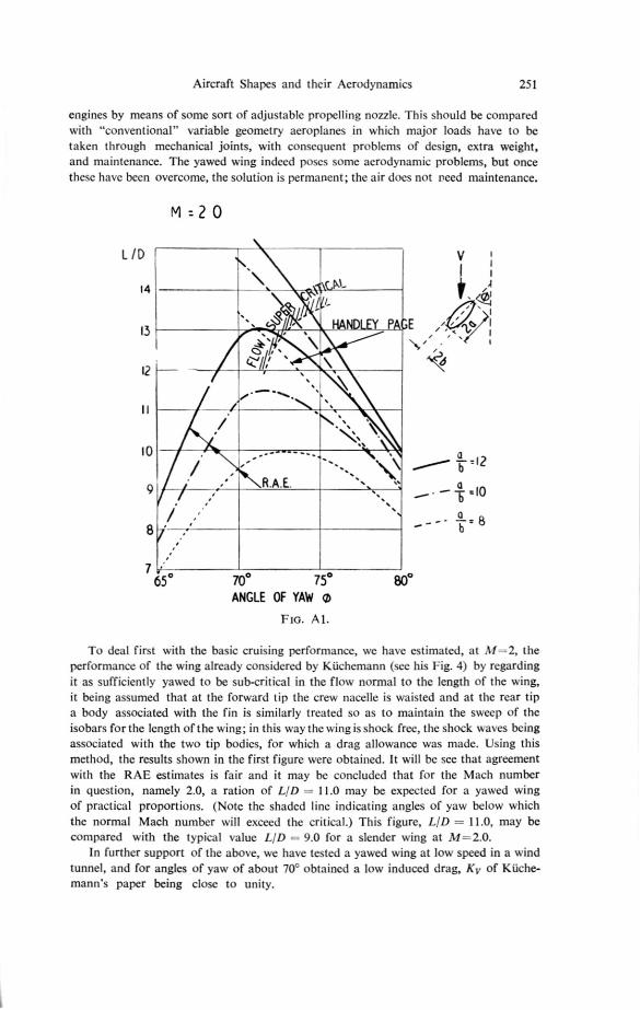
To deal first with the basic cruising performance, we have estimated, at M-2, theperformance of the wing already considered by Küchemann (see his Fig. 4) by regardingit as sufficiently yawed to be sub-critical in the flow normal to the length of the wing,it being assumed that at the forward tip the crew nacelle is waisted and at the rear tipa body associated with the fin is similarly treated so as to maintain the sweep of theisobars for the length of the wing; in this way the wing is shock free, the shock waves bcingassociated with the two tip bodies, for which a drag allowance was made. Using thismethod, the results shown in the first figure were obtained. It will be see that agreementwith the RAE estimates is fair and it may be concluded that for the Mach numberin question, namely 2.0, a ration of LID = 11.0 may be expected for a yawed wingof practical proportions. (Note the shaded line indicating angles of yaw below whichthe normal Mach number will exceed the critical.) This figure, LID =11.0, may becompared with the typical value LID — 9.0 for a slender wing at M=2.0.
In further support of the above, we have tested a yawed wing at low speed in a windtunnel, and for angles of yaw of about 70' obtained a low induced drag, K. of Küche-mann's paper being close to unity.
252 D. KecnErstANN
However, a supersonic aeroplane spends much of its time flying non-supersonically,(for take-off and landing, climb, stand-off, etc) and it is in such phases that variablegeometry pays. Subsonically, the yawed aircraft flies best at M 0.34, with 300 ofyaw and with LID = 24, far higher than a slender wing under comparable conditions.
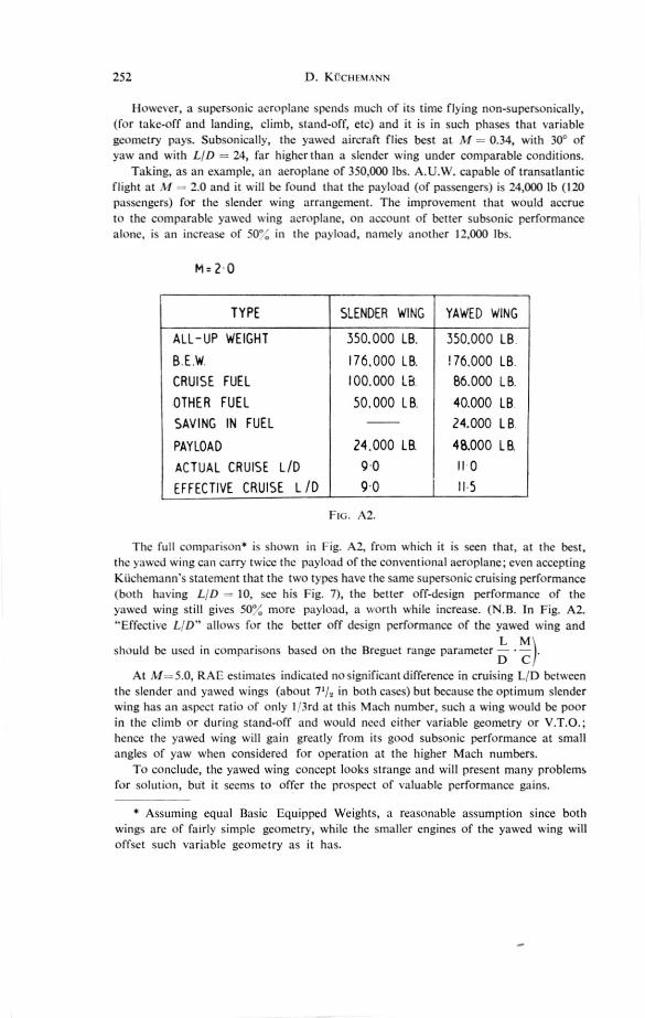
Taking, as an example, an aeroplane of 350,000 lbs. A.U.W. capable of transatlanticflight at M 2.0 and it will be found that the payload (of passengers) is 24,000 lb (120passengers) for the slender wing arrangement. The improvement that would accrueto the comparable yawed wing aeroplane, on account of better subsonic performancealone, is an increase of 50%, in the payload, namely another 12,000 lbs.
Mr 2 0
TYPE
ALL-UP WEIGHT
B E W.
CRUISE FUEL
OTHER FUEL
SAVING IN FUEL
PAYLOAD
ACTUAL CRUISE L/D
EFFECTIVE CRUISE L /D
SLENDER WING
350.000 LB.
176,000 LB.
100.000 LB
50,000 LB.
YAWED WING
350.000 LB
176,000 LB
86.000 LB
40.000 LB
24.000 LB
48.000 LB
II 0
II 5
24.000 La
9.0
9.0
FIG. A2.
The full comparison* is shown in Fig. A2, from which it is seen that, at the best,the yawed wing can carry twice the payload of the conventional aeroplane; even acceptingKiichemann's statement that the two types have the same supersonic cruising performance(both having L/D 10, see his Fig. 7), the better off-design performance of theyawed wing still gives 50% more payload, a worth while increase. (N.B. In Fig. A2."Effective L!D" allows for the better off design performance of the yawed wing and
L Mshould be used in comparisons based on the Breguet range parameter — • —).
D CAt M =5.0, RAE estimates indicated no significant difference in cruising 1_,T) between
the slender and yawed wings (about in both cases) but because the optimum slenderwing has an aspect ratio of only I '3rd at this Mach number, such a wing would be poorin the climb or during stand-off and would need either variable geometry or V.T.O.;hence the yawed wing will gain greatly from its good subsonic performance at smallangles of yaw when considered for operation at the higher Mach numbers.
To conclude, the yawed wing concept looks strange and will present many problemsfor solution, bdt it seems to offer the prospect of valuable performance gains.
* Assuming equal Basic Equipped Weights, a reasonable assumption since bothwings are of fairly simple geometry, while the smaller engines of the yawed wing willoffset such variable geometry as it has.