Embed Size (px)
Citation preview

@AIRBUSA380
AIRCRAFT CHARACTERISTICSAIRPORT AND MAINTENANCE PLANNING
AC
The content of this document is the property of Airbus.It is supplied in confidence and commercial security on its contents must be maintained.It must not be used for any purpose other than that for which it is supplied, nor mayinformation contained in it be disclosed to unauthorized persons.It must not be reproduced in whole or in part without permission in writing from the owners ofthe copyright. Requests for reproduction of any data in this document and the media authorizedfor it must be addressed to Airbus.
© AIRBUS S.A.S. 2005. All rights reserved.
AIRBUS S.A.S.Customer Services
Technical Data Support and Services31707 Blagnac Cedex
FRANCE
Issue: Mar 30/05 Rev: Dec 01/16

@A380AIRCRAFT CHARACTERISTICS - AIRPORT AND MAINTENANCE PLANNING
HIGHLIGHTS
Revision No. 15 - Dec 01/16
LOCATIONS CHGCODE
DESCRIPTIONS OF CHANGE
CHAPTER 2
Section 2-1
Subject 2-1-1
General Aircraft Characteristics Data R
Section 2-6
Subject 2-6-0
FIGURE Cargo Compartments - Locationand Dimensions
R
FIGURE Cargo Compartments - LoadingCombinations
R
Section 2-9
Subject 2-9-0
Landing Gear R
FIGURE Nose Landing Gear - General R REVISED THE ILLUSTRATION (SHEET 3)TO SHOW TOW TRUCK POWERCONNECTOR.
Section 2-14
Subject 2-14-0
Jacking for Maintenance R
Jacking of the Landing Gear R DESCRIPTION TITLE UPDATEDNOTE AMENDED
CHAPTER 5
Section 5-4
Subject 5-4-4
Electrical Servicing R
CHAPTER 7
Section 7-1
Subject 7-1-0
General Information R
HIGHLIGHTSPage 1
Dec 01/16
@A380AIRCRAFT CHARACTERISTICS - AIRPORT AND MAINTENANCE PLANNING
LOCATIONS CHGCODE
DESCRIPTIONS OF CHANGE
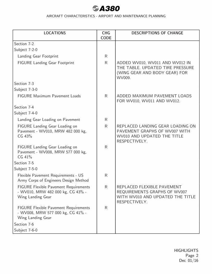
Section 7-2
Subject 7-2-0
Landing Gear Footprint R
FIGURE Landing Gear Footprint R ADDED WV010, WV011 AND WV012 INTHE TABLE. UPDATED TIRE PRESSURE(WING GEAR AND BODY GEAR) FORWV009.
Section 7-3
Subject 7-3-0
FIGURE Maximum Pavement Loads R ADDED MAXIMUM PAVEMENT LOADSFOR WV010, WV011 AND WV012.
Section 7-4
Subject 7-4-0
Landing Gear Loading on Pavement R
FIGURE Landing Gear Loading onPavement - WV010, MRW 482 000 kg,CG 43%
R REPLACED LANDING GEAR LOADING ONPAVEMENT GRAPHS OF WV007 WITHWV010 AND UPDATED THE TITLERESPECTIVELY.
FIGURE Landing Gear Loading onPavement - WV008, MRW 577 000 kg,CG 41%
R
Section 7-5
Subject 7-5-0
Flexible Pavement Requirements - USArmy Corps of Engineers Design Method
R
FIGURE Flexible Pavement Requirements- WV010, MRW 482 000 kg, CG 43% -Wing Landing Gear
R REPLACED FLEXIBLE PAVEMENTREQUIREMENTS GRAPHS OF WV007WITH WV010 AND UPDATED THE TITLERESPECTIVELY.
FIGURE Flexible Pavement Requirements- WV008, MRW 577 000 kg, CG 41% -Wing Landing Gear
R
Section 7-6
Subject 7-6-0
HIGHLIGHTSPage 2
Dec 01/16
@A380AIRCRAFT CHARACTERISTICS - AIRPORT AND MAINTENANCE PLANNING
LOCATIONS CHGCODE
DESCRIPTIONS OF CHANGE
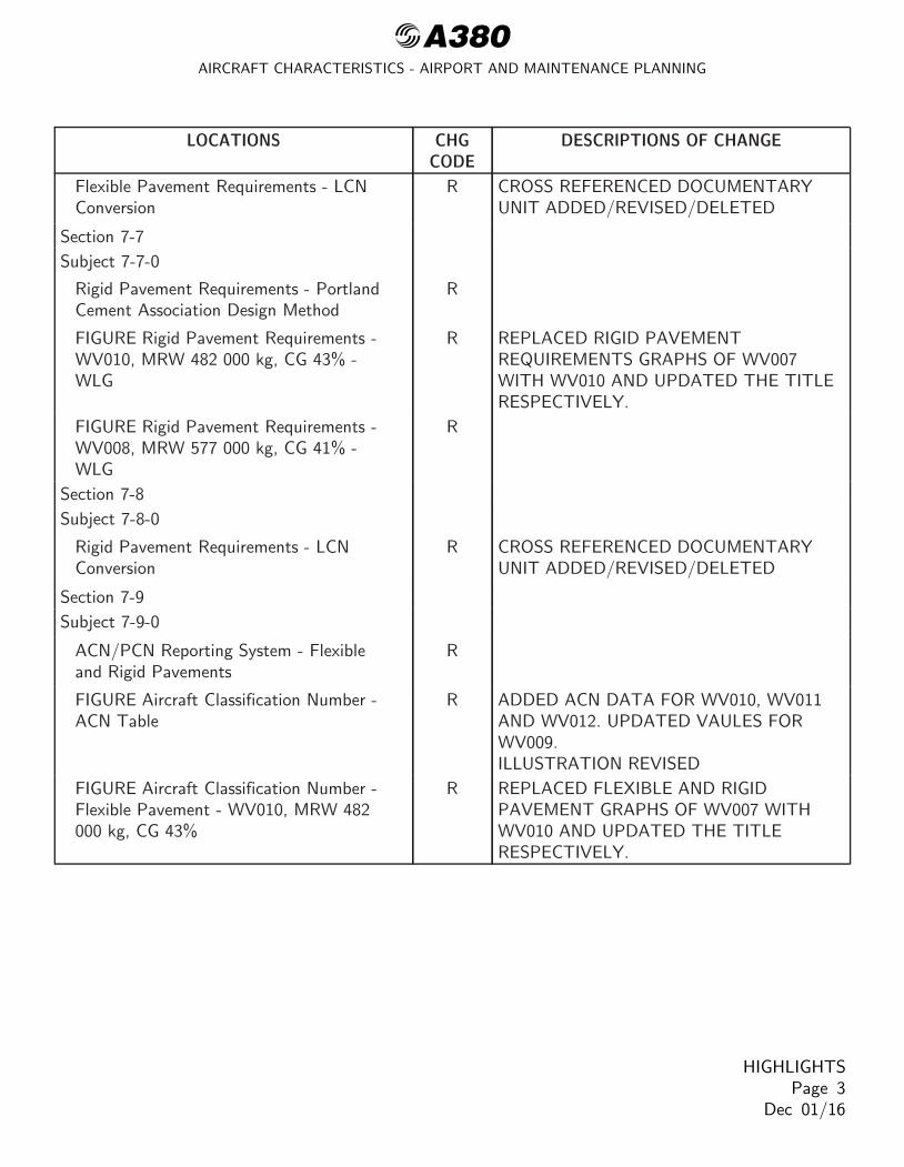
Flexible Pavement Requirements - LCNConversion
R CROSS REFERENCED DOCUMENTARYUNIT ADDED/REVISED/DELETED
Section 7-7
Subject 7-7-0
Rigid Pavement Requirements - PortlandCement Association Design Method
R
FIGURE Rigid Pavement Requirements -WV010, MRW 482 000 kg, CG 43% -WLG
R REPLACED RIGID PAVEMENTREQUIREMENTS GRAPHS OF WV007WITH WV010 AND UPDATED THE TITLERESPECTIVELY.
FIGURE Rigid Pavement Requirements -WV008, MRW 577 000 kg, CG 41% -WLG
R
Section 7-8
Subject 7-8-0
Rigid Pavement Requirements - LCNConversion
R CROSS REFERENCED DOCUMENTARYUNIT ADDED/REVISED/DELETED
Section 7-9
Subject 7-9-0
ACN/PCN Reporting System - Flexibleand Rigid Pavements
R
FIGURE Aircraft Classification Number -ACN Table
R ADDED ACN DATA FOR WV010, WV011AND WV012. UPDATED VAULES FORWV009.ILLUSTRATION REVISED
FIGURE Aircraft Classification Number -Flexible Pavement - WV010, MRW 482000 kg, CG 43%
R REPLACED FLEXIBLE AND RIGIDPAVEMENT GRAPHS OF WV007 WITHWV010 AND UPDATED THE TITLERESPECTIVELY.
HIGHLIGHTSPage 3
Dec 01/16
@A380AIRCRAFT CHARACTERISTICS - AIRPORT AND MAINTENANCE PLANNING
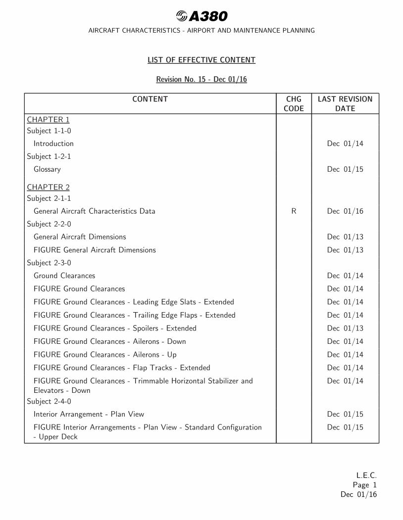
LIST OF EFFECTIVE CONTENT
Revision No. 15 - Dec 01/16
CONTENT CHGCODE
LAST REVISIONDATE
CHAPTER 1
Subject 1-1-0
Introduction Dec 01/14
Subject 1-2-1
Glossary Dec 01/15
CHAPTER 2
Subject 2-1-1
General Aircraft Characteristics Data R Dec 01/16
Subject 2-2-0
General Aircraft Dimensions Dec 01/13
FIGURE General Aircraft Dimensions Dec 01/13
Subject 2-3-0
Ground Clearances Dec 01/14
FIGURE Ground Clearances Dec 01/14
FIGURE Ground Clearances - Leading Edge Slats - Extended Dec 01/14
FIGURE Ground Clearances - Trailing Edge Flaps - Extended Dec 01/14
FIGURE Ground Clearances - Spoilers - Extended Dec 01/13
FIGURE Ground Clearances - Ailerons - Down Dec 01/14
FIGURE Ground Clearances - Ailerons - Up Dec 01/14
FIGURE Ground Clearances - Flap Tracks - Extended Dec 01/14
FIGURE Ground Clearances - Trimmable Horizontal Stabilizer andElevators - Down
Dec 01/14
Subject 2-4-0
Interior Arrangement - Plan View Dec 01/15
FIGURE Interior Arrangements - Plan View - Standard Configuration- Upper Deck
Dec 01/15
L.E.C.Page 1
Dec 01/16

@A380AIRCRAFT CHARACTERISTICS - AIRPORT AND MAINTENANCE PLANNING
CONTENT CHGCODE
LAST REVISIONDATE
FIGURE Interior Arrangements - Plan View - Standard Configuration- Main Deck
Dec 01/15
Subject 2-5-0
Interior Arrangements - Cross Section Dec 01/15
FIGURE Interior Arrangements - Cross Section - TypicalConfiguration - Upper Deck
Dec 01/15
FIGURE Interior Arrangements - Cross Section - TypicalConfiguration - Main Deck
Dec 01/15
Subject 2-6-0
Cargo Compartments Dec 01/15
FIGURE Cargo Compartments - Location and Dimensions R Dec 01/16
FIGURE Cargo Compartments - Loading Combinations R Dec 01/16
Subject 2-7-0
Door Clearances Dec 01/14
FIGURE Door Clearances - Door Location (Sheet 1) Dec 01/13
FIGURE Door Clearances - Door Location (Sheet 2) Dec 01/13
FIGURE Door Clearances - Forward Passenger Doors Dec 01/15
FIGURE Door Clearances - Main and Upper Deck Passenger Doors Dec 01/15
FIGURE Door Clearances - Aft Passenger Doors Dec 01/15
FIGURE Door Clearances - Forward Cargo Compartment Door Dec 01/15
FIGURE Door Clearances - Aft Cargo Compartment Doors Dec 01/15
FIGURE Door Clearances - Forward Nose Landing Gear Doors Dec 01/15
FIGURE Door Clearances - Wing Landing Gears - Main Doors Dec 01/14
FIGURE Door Clearances - Body Landing Gears - Outer Doors Dec 01/14
FIGURE Door Clearances - APU Doors Dec 01/14
Subject 2-8-0
Escape Slides Dec 01/15
FIGURE Escape Slides - Location Dec 01/15
FIGURE Escape Slides - Dimensions Dec 01/15
Subject 2-9-0
L.E.C.Page 2
Dec 01/16

@A380AIRCRAFT CHARACTERISTICS - AIRPORT AND MAINTENANCE PLANNING
CONTENT CHGCODE
LAST REVISIONDATE
Landing Gear R Dec 01/16
FIGURE Wing Landing Gear - General Dec 01/15
FIGURE Body Landing Gear - General Dec 01/15
FIGURE Nose Landing Gear - General R Dec 01/16
Landing Gear Maintenance Pits Dec 01/15
FIGURE Landing Gear Maintenance Pits - Maintenance Pit Envelopes Dec 01/13
FIGURE Landing Gear Maintenance Pits - Necessary Depths Dec 01/13
FIGURE Landing Gear Maintenance Pits - Maintenance Pit Envelopes- WLG Pit Dimensions
Dec 01/13
FIGURE Landing Gear Maintenance Pits - Maintenance Pit Envelopes- BLG Pit Dimensions
Dec 01/13
Subject 2-10-0
Exterior Lighting Dec 01/13
FIGURE Exterior Lighting Dec 01/13
FIGURE Exterior Lighting Dec 01/13
FIGURE Exterior Lighting Dec 01/13
FIGURE Exterior Lighting Dec 01/13
FIGURE Exterior Lighting Dec 01/13
Subject 2-11-0
Antennas and Probes Location Dec 01/13
FIGURE Antennas and Probes - Location Dec 01/13
Subject 2-12-0
Auxiliary Power Unit Dec 01/13
FIGURE Auxiliary Power Unit - Access Doors Dec 01/13
FIGURE Auxiliary Power Unit - General Layout Dec 01/13
Engine and Nacelle Dec 01/13
FIGURE Power Plant Handling - Engine Dimensions - GP 7200Engine
Dec 01/13
FIGURE Power Plant Handling - Nacelle Dimensions - GP 7200Engine
Dec 01/13
L.E.C.Page 3
Dec 01/16

@A380AIRCRAFT CHARACTERISTICS - AIRPORT AND MAINTENANCE PLANNING
CONTENT CHGCODE
LAST REVISIONDATE
FIGURE Power Plant Handling - Fan Cowls - GP 7200 Engine Dec 01/13
FIGURE Power Plant Handling - Thrust Reverser Cowls - GP 7200Engine
Dec 01/13
FIGURE Power Plant Handling - Fan Exhaust Cowls - GP 7200Engine
Dec 01/15
FIGURE Power Plant Handling - Engine Dimensions - TRENT 900Engine
Dec 01/13
FIGURE Power Plant Handling - Nacelle Dimensions - TRENT 900Engine
Dec 01/13
FIGURE Power Plant Handling - Fan Cowls - TRENT 900 Engine Dec 01/13
FIGURE Power Plant Handling - Thrust Reverser Cowls - TRENT900 Engine
Dec 01/13
FIGURE Power Plant Handling - Fan Exhaust Cowls - TRENT 900Engine
Dec 01/15
Subject 2-13-0
Leveling, Symmetry and Alignment Dec 01/13
FIGURE Location of Leveling Points Dec 01/13
Subject 2-14-0
Jacking for Maintenance R Dec 01/16
FIGURE Jacking for Maintenance - Jacking Points Location Dec 01/13
FIGURE Jacking for Maintenance - Jacking Dimensions Dec 01/13
FIGURE Jacking for Maintenance - Forward Jacking Point Dec 01/13
FIGURE Jacking for Maintenance - Wing Jacking Point Dec 01/13
FIGURE Jacking for Maintenance - Auxiliary Jacking Point - SafetyStay
Dec 01/13
Jacking of the Landing Gear R Dec 01/16
FIGURE Nose Landing Gear Jacking Point Heights Dec 01/13
FIGURE Wing Landing Gear Jacking Point Heights Dec 01/13
FIGURE Body Landing Gear Jacking Point Heights Dec 01/13
CHAPTER 3
Subject 3-1-0
L.E.C.Page 4
Dec 01/16

@A380AIRCRAFT CHARACTERISTICS - AIRPORT AND MAINTENANCE PLANNING
CONTENT CHGCODE
LAST REVISIONDATE
General Information Dec 01/13
Subject 3-2-1
Payload/Range - ISA Conditions Dec 01/14
FIGURE Payload/Range - ISA Conditions - TRENT 900 Engines Dec 01/13
FIGURE Payload/Range - ISA Conditions - GP 7200 Engines Dec 01/13
Subject 3-3-1
Take-Off Weight Limitation - ISA Conditions Dec 01/14
FIGURE Take-Off Weight Limitation - ISA Conditions - TRENT 900Engines
Dec 01/14
FIGURE Take-Off Weight Limitation - ISA Conditions - GP 7200Engines
Dec 01/14
Subject 3-3-2
Take-Off Weight Limitation - ISA + 15 ˚C (+59 ˚F) Conditions Dec 01/14
FIGURE Take-Off Weight Limitation - ISA + 15 ˚C (+59 ˚F)Conditions - TRENT 900 Engines
Dec 01/14
FIGURE Take-Off Weight Limitation - ISA + 15 ˚C (+59 ˚F)Conditions - GP 7200 Engines
Dec 01/14
Subject 3-4-1
Landing Field Length Dec 01/14
FIGURE Landing Field Length - Dry Runway Dec 01/14
Subject 3-5-0
Final Approach Speed Dec 01/13
CHAPTER 4
Subject 4-1-0
General Dec 01/13
Subject 4-2-0
Turning Radii Dec 01/14
FIGURE Turning Radii - (Sheet 1) Dec 01/14
FIGURE Turning Radii - (Sheet 2) Dec 01/14
Subject 4-3-0
L.E.C.Page 5
Dec 01/16

@A380AIRCRAFT CHARACTERISTICS - AIRPORT AND MAINTENANCE PLANNING
CONTENT CHGCODE
LAST REVISIONDATE
Minimum Turning Radii Dec 01/14
FIGURE Minimum Turning Radii Dec 01/14
Subject 4-4-0
Visibility from Cockpit in Static Position Dec 01/13
FIGURE Visibility from Cockpit in Static Position Dec 01/13
FIGURE Binocular Visibility Through Windows from Captain EyePosition
Dec 01/13
Subject 4-5-0
Runway and Taxiway Turn Paths Dec 01/13
Subject 4-5-1
135˚ Turn - Runway to Taxiway Dec 01/13
FIGURE 135˚ Turn -- Runway to Taxiway - Judgemental OversteerMethod
Dec 01/13
FIGURE 135˚ Turn -- Runway to Taxiway - Cockpit TracksCentreline Method
Dec 01/13
Subject 4-5-2
90˚ Turn - Runway to Taxiway Dec 01/13
FIGURE 90˚ Turn -- Runway to Taxiway - Judgemental OversteerMethod
Dec 01/13
FIGURE 90˚ Turn -- Runway to Taxiway - Cockpit Tracks CentrelineMethod
Dec 01/13
Subject 4-5-3
180˚ Turn on a Runway Dec 01/13
FIGURE 180˚ Turn on a Runway Dec 01/13
Subject 4-5-4
90˚ Turn - Taxiway to Taxiway Dec 01/13
FIGURE 90˚ Turn -- Taxiway to Taxiway - Judgemental OversteerMethod
Dec 01/13
FIGURE 90˚ Turn -- Taxiway to Taxiway - Cockpit Tracks CentrelineMethod
Dec 01/13
Subject 4-5-5
135˚ Turn - Taxiway to Taxiway Dec 01/13
L.E.C.Page 6
Dec 01/16

@A380AIRCRAFT CHARACTERISTICS - AIRPORT AND MAINTENANCE PLANNING
CONTENT CHGCODE
LAST REVISIONDATE
FIGURE 135˚ Turn -- Taxiway to Taxiway - Judgemental OversteerMethod
Dec 01/13
FIGURE 135˚ Turn -- Taxiway to Taxiway - Cockpit TracksCenterline Method
Dec 01/13
Subject 4-6-0
Runway Holding Bay (Apron) Dec 01/13
FIGURE Runway Holding Bay (Apron) Dec 01/13
Subject 4-7-0
Minimum Line-Up Distance Corrections Dec 01/13
FIGURE Minimum Line-Up Distance Corrections - 90˚ Turn onRunway Entry
Dec 01/13
FIGURE Minimum Line-Up Distance Corrections - 180˚ Turn onRunway Turn Pad
Dec 01/13
FIGURE Minimum Line-Up Distance Corrections - 180˚ Turn onRunway Width
Dec 01/13
Subject 4-8-0
Aircraft Mooring Dec 01/13
FIGURE Aircraft Mooring Dec 01/13
CHAPTER 5
Subject 5-1-0
Aircraft Servicing Arrangements Dec 01/14
Subject 5-1-1
Typical Ramp Layout (Open Apron) Dec 01/15
FIGURE Typical Ramp Layout - Open Apron Dec 01/13
Subject 5-1-2
Typical Ramp Layout (Gate) Dec 01/15
FIGURE Typical Ramp Layout - Gate Dec 01/13
Subject 5-2-1
Typical Turn-Round Time - Standard Servicing Via Main Deck andUpper Deck
Dec 01/14
L.E.C.Page 7
Dec 01/16

@A380AIRCRAFT CHARACTERISTICS - AIRPORT AND MAINTENANCE PLANNING
CONTENT CHGCODE
LAST REVISIONDATE
FIGURE Typical Turn-Round Time - Servicing Via Main and UpperDeck
Dec 01/14
Subject 5-2-2
Typical Turn-Round Time - Servicing Via Main Deck Dec 01/14
FIGURE Typical Turn-Round Time - Servicing Via Main Deck Dec 01/14
Subject 5-4-1
Ground Service Connections Layout Dec 01/13
FIGURE Ground Service Connections Layout Dec 01/13
Subject 5-4-2
Grounding (Earthing) Points Dec 01/14
FIGURE Grounding (Earthing) Point - NLG Dec 01/14
FIGURE Grounding (Earthing) Points - WLG Dec 01/14
FIGURE Grounding (Earthing) Points - BLG Dec 01/14
Subject 5-4-3
Hydraulic Servicing Dec 01/15
FIGURE Ground Service Connections - Hydraulic Reservoir ServicingPanel
Dec 01/14
FIGURE Ground Service Connections - Hydraulic Ground Connections Dec 01/13
Subject 5-4-4
Electrical Servicing R Dec 01/16
FIGURE Ground Service Connections - Electrical Service Panel Dec 01/13
FIGURE Ground Service Connections - Ram Air Turbine Retracted Dec 01/14
FIGURE Ground Service Connections - Ram Air Turbine Extended Dec 01/14
Subject 5-4-5
Oxygen System Dec 01/14
FIGURE Ground Service Connections - Oxygen System Dec 01/13
Subject 5-4-6
Fuel Servicing Dec 01/15
FIGURE Ground Service Connections - Refuel/Defuel Control Panel Dec 01/13
FIGURE Ground Service Connections - Pressure Refuel Connections Dec 01/13
L.E.C.Page 8
Dec 01/16

@A380AIRCRAFT CHARACTERISTICS - AIRPORT AND MAINTENANCE PLANNING
CONTENT CHGCODE
LAST REVISIONDATE
FIGURE Ground Service Connections - Overpressure Protector andNACA Flame Arrestor - Wing
Dec 01/14
FIGURE Ground Service Connections - Overpressure Protector andNACA Flame Arrestor - Trim Tank
Dec 01/14
Subject 5-4-7
Pneumatic Servicing Dec 01/15
FIGURE Ground Service Connections - Low Pressure PreconditionedAir
Dec 01/13
FIGURE Ground Service Connections - High Pressure PreconditionedAir
Dec 01/13
Subject 5-4-8
Oil Servicing Dec 01/15
FIGURE Ground Service Connections - Engine Oil Servicing - TRENT900 Engines
Dec 01/15
FIGURE Ground Service Connections - VFG Oil Servicing - TRENT900 Engines
Dec 01/15
FIGURE Ground Service Connections - Starter Oil Servicing - TRENT900 Engines
Dec 01/15
FIGURE Ground Service Connections - Engine Oil Servicing - GP7200Engines
Dec 01/15
FIGURE Ground Service Connections - VFG Oil Servicing - GP7200Engines
Dec 01/15
FIGURE Ground Service Connections - Starter Oil Servicing - GP7200Engines
Dec 01/15
FIGURE Ground Service Connections - APU Oil Servicing Dec 01/15
Subject 5-4-9
Potable Water Servicing Dec 01/15
FIGURE Ground Service Connections - Potable Water Ground ServicePanel
Dec 01/14
FIGURE Ground Service Connections - Potable Water Drain Panel Dec 01/14
FIGURE Ground Service Connections - Potable Water Tanks Location Dec 01/14
Subject 5-4-10
Waste Water System Dec 01/14
L.E.C.Page 9
Dec 01/16

@A380AIRCRAFT CHARACTERISTICS - AIRPORT AND MAINTENANCE PLANNING
CONTENT CHGCODE
LAST REVISIONDATE
FIGURE Ground Service Connections - Waste Water Ground ServicePanel
Dec 01/14
FIGURE Ground Service Connections - Waste Tanks Location Dec 01/13
Subject 5-4-11
Cargo Control Panels Dec 01/15
FIGURE Forward Cargo Control Panels Dec 01/14
FIGURE Aft Cargo Control Panels Dec 01/14
Subject 5-5-0
Engine Starting Pneumatic Requirements Dec 01/13
FIGURE Example for Use of the Charts Dec 01/13
FIGURE Engine Starting Pneumatic Requirements - Engine Alliance -GP 7200
Dec 01/13
FIGURE Engine Starting Pneumatic Requirements - Rolls Royce -Trent 900 Engine
Dec 01/13
Subject 5-6-0
Ground Pneumatic Power Requirements Dec 01/15
FIGURE Ground Pneumatic Power Requirements - Heating Dec 01/13
FIGURE Ground Pneumatic Power Requirements - Cooling Dec 01/13
Subject 5-7-0
Preconditioned Airflow Requirements Dec 01/15
FIGURE Preconditioned Airflow Requirements Dec 01/13
Subject 5-8-0
Ground Towing Requirements Dec 01/15
FIGURE Ground Towing Requirements Dec 01/13
FIGURE Ground Towing Requirements - Nose Gear Towing Fittings Dec 01/13
Subject 5-9-0
De-Icing and External Cleaning Dec 01/15
CHAPTER 6
Subject 6-1-0
Engine Exhaust Velocities and Temperatures Dec 01/14
L.E.C.Page 10
Dec 01/16
@A380AIRCRAFT CHARACTERISTICS - AIRPORT AND MAINTENANCE PLANNING
CONTENT CHGCODE
LAST REVISIONDATE
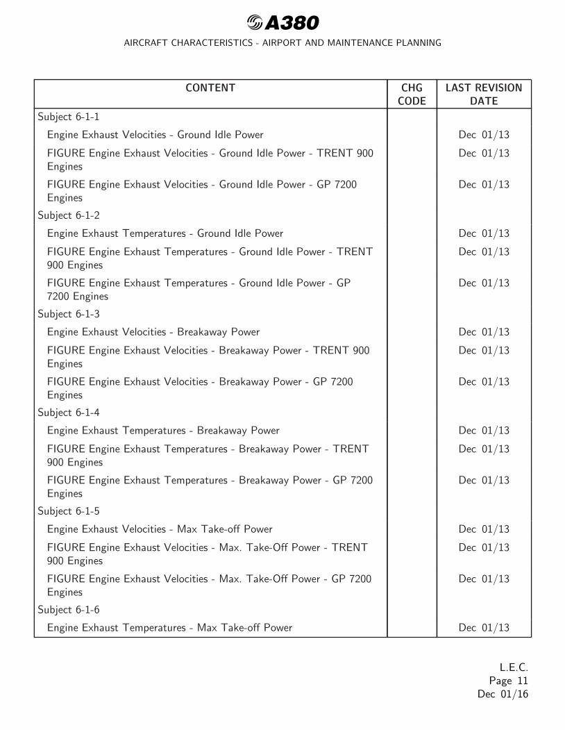
Subject 6-1-1
Engine Exhaust Velocities - Ground Idle Power Dec 01/13
FIGURE Engine Exhaust Velocities - Ground Idle Power - TRENT 900Engines
Dec 01/13
FIGURE Engine Exhaust Velocities - Ground Idle Power - GP 7200Engines
Dec 01/13
Subject 6-1-2
Engine Exhaust Temperatures - Ground Idle Power Dec 01/13
FIGURE Engine Exhaust Temperatures - Ground Idle Power - TRENT900 Engines
Dec 01/13
FIGURE Engine Exhaust Temperatures - Ground Idle Power - GP7200 Engines
Dec 01/13
Subject 6-1-3
Engine Exhaust Velocities - Breakaway Power Dec 01/13
FIGURE Engine Exhaust Velocities - Breakaway Power - TRENT 900Engines
Dec 01/13
FIGURE Engine Exhaust Velocities - Breakaway Power - GP 7200Engines
Dec 01/13
Subject 6-1-4
Engine Exhaust Temperatures - Breakaway Power Dec 01/13
FIGURE Engine Exhaust Temperatures - Breakaway Power - TRENT900 Engines
Dec 01/13
FIGURE Engine Exhaust Temperatures - Breakaway Power - GP 7200Engines
Dec 01/13
Subject 6-1-5
Engine Exhaust Velocities - Max Take-off Power Dec 01/13
FIGURE Engine Exhaust Velocities - Max. Take-Off Power - TRENT900 Engines
Dec 01/13
FIGURE Engine Exhaust Velocities - Max. Take-Off Power - GP 7200Engines
Dec 01/13
Subject 6-1-6
Engine Exhaust Temperatures - Max Take-off Power Dec 01/13
L.E.C.Page 11
Dec 01/16

@A380AIRCRAFT CHARACTERISTICS - AIRPORT AND MAINTENANCE PLANNING
CONTENT CHGCODE
LAST REVISIONDATE
FIGURE Engine Exhaust Temperatures - Max Take-Off Power -TRENT 900 Engines
Dec 01/13
FIGURE Engine Exhaust Temperatures - Max Take-Off Power - GP7200 Engines
Dec 01/13
Subject 6-3-0
Danger Areas of the Engines Dec 01/13
Subject 6-3-1
Danger Areas of the Engines - Ground Idle Power Dec 01/13
FIGURE Danger Areas of the Engines - Ground Idle Power - TRENT900 Engines
Dec 01/13
FIGURE Danger Areas of the Engines - Ground Idle Power - GP 7200Engines
Dec 01/13
Subject 6-3-2
Danger Areas of the Engines - Max. Take-Off Power Dec 01/13
FIGURE Danger Areas of the Engines - Max Take-Off Power -TRENT 900 Engines
Dec 01/13
FIGURE Danger Areas of the Engines - Max Take-Off Power - GP7200 Engines
Dec 01/13
Subject 6-3-3
Danger Areas of the Engines - Breakaway Power Dec 01/13
FIGURE Danger Areas of the Engines - Breakaway Power - TRENT900 Engines
Dec 01/13
FIGURE Danger Areas of the Engines - Breakaway Power - GP 7200Engines
Dec 01/13
Subject 6-4-1
APU Exhaust Velocities and Temperatures - ECS Conditions Dec 01/14
FIGURE APU Exhaust Velocities and Temperatures - Max. ECSConditions
Dec 01/13
Subject 6-4-2
APU Exhaust Velocities and Temperatures - MES Conditions Dec 01/13
FIGURE APU Exhaust Velocities and Temperatures - MES Conditions Dec 01/13
CHAPTER 7
L.E.C.Page 12
Dec 01/16

@A380AIRCRAFT CHARACTERISTICS - AIRPORT AND MAINTENANCE PLANNING
CONTENT CHGCODE
LAST REVISIONDATE
Subject 7-1-0
General Information R Dec 01/16
Subject 7-2-0
Landing Gear Footprint R Dec 01/16
FIGURE Landing Gear Footprint R Dec 01/16
Subject 7-3-0
Maximum Pavement Loads Dec 01/14
FIGURE Maximum Pavement Loads R Dec 01/16
Subject 7-4-0
Landing Gear Loading on Pavement R Dec 01/16
FIGURE Landing Gear Loading on Pavement - WV010, MRW 482000 kg, CG 43%
R Dec 01/16
FIGURE Landing Gear Loading on Pavement - WV008, MRW 577000 kg, CG 41%
R Dec 01/16
Subject 7-5-0
Flexible Pavement Requirements - US Army Corps of EngineersDesign Method
R Dec 01/16
FIGURE Flexible Pavement Requirements - WV010, MRW 482 000kg, CG 43% - Wing Landing Gear
R Dec 01/16
FIGURE Flexible Pavement Requirements - WV008, MRW 577 000kg, CG 41% - Wing Landing Gear
R Dec 01/16
Subject 7-6-0
Flexible Pavement Requirements - LCN Conversion R Dec 01/16
Subject 7-7-0
Rigid Pavement Requirements - Portland Cement Association DesignMethod
R Dec 01/16
FIGURE Rigid Pavement Requirements - WV010, MRW 482 000 kg,CG 43% - WLG
R Dec 01/16
FIGURE Rigid Pavement Requirements - WV008, MRW 577 000 kg,CG 41% - WLG
R Dec 01/16
Subject 7-8-0
Rigid Pavement Requirements - LCN Conversion R Dec 01/16
L.E.C.Page 13
Dec 01/16

@A380AIRCRAFT CHARACTERISTICS - AIRPORT AND MAINTENANCE PLANNING
CONTENT CHGCODE
LAST REVISIONDATE
Subject 7-9-0
ACN/PCN Reporting System - Flexible and Rigid Pavements R Dec 01/16
FIGURE Aircraft Classification Number - ACN Table R Dec 01/16
FIGURE Aircraft Classification Number - Flexible Pavement - WV010,MRW 482 000 kg, CG 43%
R Dec 01/16
FIGURE Aircraft Classification Number - Flexible Pavement - WV008,MRW 577 000 kg, CG 41%
Dec 01/14
CHAPTER 8
Subject 8-0-0
Scaled Drawings Dec 01/13
FIGURE Scaled Drawing Dec 01/13
CHAPTER 10
Subject 10-0-0
Aircraft Rescue and Fire Fighting Dec 01/15
FIGURE Front Page Dec 01/15
FIGURE Highly Flammable and Hazardous Materials and Components Dec 01/15
FIGURE Batteries Location and Access Dec 01/15
FIGURE Crew Rest Compartments Location Dec 01/13
FIGURE Wheel/Brake Overheat - Wheel Safety Area Dec 01/13
FIGURE Composite Materials Location Dec 01/13
FIGURE Landing Gear - Ground Lock Safety Devices Dec 01/13
FIGURE Emergency Evacuation Devices Dec 01/15
FIGURE Pax/Crew Doors and Emergency Exits Dec 01/13
FIGURE Cargo Doors - FWD and AFT Lower Deck Cargo Doors Dec 01/13
FIGURE Control Panels Dec 01/13
FIGURE APU Compartment Access Dec 01/13
FIGURE Aircraft Ground Clearances Dec 01/15
FIGURE Structural Break-in Points Dec 01/13
L.E.C.Page 14
Dec 01/16

@A380AIRCRAFT CHARACTERISTICS - AIRPORT AND MAINTENANCE PLANNING
TABLE OF CONTENTS
1 SCOPE
1-1-0 Introduction
1-2-1 Glossary
2 AIRCRAFT DESCRIPTION
2-1-1 General Aircraft Characteristics Data
2-2-0 General Aircraft Dimensions
2-3-0 Ground Clearances
2-4-0 Interior Arrangement - Plan View
2-5-0 Interior Arrangements - Cross Section
2-6-0 Cargo Compartments
2-7-0 Door Clearances
2-8-0 Escape Slides
2-9-0 Landing Gear
2-10-0 Exterior Lighting
2-11-0 Antennas and Probes Location
2-12-0 Power Plant
2-13-0 Leveling, Symmetry and Alignment
2-14-0 Jacking
3 AIRCRAFT PERFORMANCE
3-1-0 General Information
3-2-1 Payload/Range - ISA Conditions
3-3-1 Take Off Weight Limitation - ISA Conditions
3-3-2 Take Off Weight Limitation - ISA + 15 ˚C (59 ˚F) Conditions
3-4-1 Landing Field Length - ISA Conditions
3-5-0 Final Approach Speed
4 GROUND MANEUVERING
4-1-0 General Information
4-2-0 Turning Radii
4-3-0 Minimum Turning Radii
4-4-0 Visibility from Cockpit in Static Position
4-5-0 Runway and Taxiway Turn Paths
4-5-1 135˚ Turn - Runway to Taxiway
T.O.C.Page 1
Dec 01/16

@A380AIRCRAFT CHARACTERISTICS - AIRPORT AND MAINTENANCE PLANNING
4-5-2 90˚ Turn - Runway to Taxiway
4-5-3 180˚ Turn on a Runway
4-5-4 90˚ Turn - Taxiway to Taxiway
4-5-5 135˚ Turn - Taxiway to Taxiway
4-6-0 Runway Holding Bay (Apron)
4-7-0 Minimum Line-Up Distance Corrections
4-8-0 Aircraft Mooring
5 TERMINAL SERVICING
5-1-0 Aircraft Servicing Arrangements
5-1-1 Typical Ramp Layout (Open Apron)
5-1-2 Typical Ramp Layout (Gate)
5-2-1 Typical Turn-Round Time - Standard Servicing Via Main Deck and Upper Deck
5-2-2 Typical Turn-Round Time - Servicing Via Main Deck
5-4-1 Ground Service Connections Layout
5-4-2 Grounding (Earthing) Points
5-4-3 Hydraulic System
5-4-4 Electrical System
5-4-5 Oxygen System
5-4-6 Fuel System
5-4-7 Pneumatic System
5-4-8 Oil System
5-4-9 Potable Water System
5-4-10 Waste Water System
5-4-11 Cargo Control Panels
5-5-0 Engine Starting Pneumatic Requirements
5-6-0 Ground Pneumatic Power Requirements
5-7-0 Preconditioned Airflow Requirements
5-8-0 Ground Towing Requirements
5-9-0 De-Icing and External Cleaning
6 OPERATING CONDITIONS
6-1-0 Engine Exhaust Velocities and Temperatures
6-1-1 Engine Exhaust Velocities - Ground Idle Power
6-1-2 Engine Exhaust Temperatures - Ground Idle Power
6-1-3 Engine Exhaust Velocities - Breakaway Power
6-1-4 Engine Exhaust Temperatures - Breakaway Power
6-1-5 Engine Exhaust Velocities - Max Take-off Power
T.O.C.Page 2
Dec 01/16

@A380AIRCRAFT CHARACTERISTICS - AIRPORT AND MAINTENANCE PLANNING
6-1-6 Engine Exhaust Temperatures - Max Take-off Power
6-3-0 Danger Areas of the Engines
6-3-1 Danger Areas of the Engines - Ground Idle Power
6-3-2 Danger Areas of the Engines - Max. Take-Off Power
6-3-3 Danger Areas of the Engines - Breakaway Power
6-4-1 APU Exhaust Velocities and Temperatures
6-4-2 APU Exhaust Velocities and Temperatures - MES Conditions
7 PAVEMENT DATA
7-1-0 General Information
7-2-0 Landing Gear Footprint
7-3-0 Maximum Pavement Loads
7-4-0 Landing Gear Loading on Pavement
7-5-0 Flexible Pavement Requirements - US Army Corps of Engineers Design Method
7-6-0 Flexible Pavement Requirements - LCN Conversion
7-7-0 Rigid Pavement Requirements - Portland Cement Association Design Method
7-8-0 Rigid Pavement Requirements - LCN Conversion
7-9-0 ACN/PCN Reporting System - Flexible and Rigid Pavements
8 SCALED DRAWINGS
8-0-0 SCALED DRAWINGS
10 AIRCRAFT RESCUE AND FIRE FIGHTING
10-0-0 AIRCRAFT RESCUE AND FIRE FIGHTING
T.O.C.Page 3
Dec 01/16

@A380AIRCRAFT CHARACTERISTICS - AIRPORT AND MAINTENANCE PLANNING
SCOPE
1-1-0 Introduction
**ON A/C A380-800
Introduction
1. GeneralThe A380 AIRCRAFT CHARACTERISTICS - AIRPORT AND MAINTENANCE PLANNING (AC)manual is issued for the A380 series aircraft to provide necessary data to airport operators, airlinesand Maintenance/Repair Organizations (MRO) for airport and maintenance facilities planning.
This document is not customized and must not be used for training purposes. No information withinmay constitute a contractual commitment.
The A380-800 is a subsonic, very long range and very high capacity civil transport aircraft. TheA380-800 offers several payload capabilities ranging from 400 passengers in a very comfortable multi-class configuration, up to 853 passengers in an all economy class configuration.
Designed in close collaboration with major airlines, airports and airworthiness authorities, the A380 isthe most advanced, spacious and productive aircraft in service setting a new standard in air traveland environmental efficiency.
The A380 Family starts from a baseline passenger aircraft - the A380-800. A higher capacity version,the A380-900 could be developed when required by the market.
Two engine types are currently offered, the Engine Alliance GP7200 series and the Rolls-Royce Trent900 series. Both engines use state of the art technology for better performance, maintainability, lowerfuel consumption and environmental impact.
The A380-800 was designed to be compatible with current airport infrastructure and equipment, asproven in service. Bigger, quieter and capable of achieving quick turn around times, the A380-800provides an efficient solution for airports and airlines to grow in a sustainable manner.
Correspondence concerning this publication should be directed to:
AIRBUS S.A.S.Customer ServicesTechnical Data Support and Services1, Rond Point Maurice BELLONTE31707 BLAGNAC CEDEXFRANCE
1-1-0Page 1
Dec 01/16

@A380AIRCRAFT CHARACTERISTICS - AIRPORT AND MAINTENANCE PLANNING
1-2-1 Glossary
**ON A/C A380-800
Glossary
1. List of Abbreviations
A/C Aircraft
ACN Aircraft Classification NumberAMM Aircraft Maintenance ManualAPU Auxiliary Power Unit
B/C Business Class
BLG Body Landing Gear
CBR California Bearing Ratio
CC Cargo Compartment
CG Center of Gravity
C/L Center Line
CLS Cargo Loading System
E Young’s Modulus
ECS Environmental Control System
ELEC Electric, Electrical, Electricity
ESWL Equivalent Single Wheel Load
FAA Federal Aviation AdministrationF/C First Class
FDL Fuselage Datum Line
FR FrameFSTE Full Size Trolley Equivalent
FWD ForwardGPU Ground Power UnitGSE Ground Support Equipment
HYD Hydraulic
ICAO International Civil Aviation Organisation
ISA International Standard Atmosphere
L Radius of Relative StiffnessLCN Load Classification NumberLD Load DeviceLD Lower DeckLH Left HandLPS Last Pax Seating
MAC Mean Aerodynamic Chord
1-2-1Page 1
Dec 01/16

@A380AIRCRAFT CHARACTERISTICS - AIRPORT AND MAINTENANCE PLANNING
MAX MaximumMD Main DeckMES Main Engine Start
MIN MinimumNLG Nose Landing Gear
OAT Outside Air Temperature
PAX Passenger
PBB Passenger Boarding Bridge
PB/D Passenger Boarding/Deplaning
PCA Portland Cement AssociationPCN Pavement Classification NumberPRM Passenger with Reduced Mobility
RH Right Hand
UD Upper Deck
ULD Unit Load DeviceUS United StatesVFG Variable Frequency Generator
WLG Wing Landing Gear
WV Weight Variant
Y/C Tourist Class
2. Design Weight Terminology- Maximum Design Ramp Weight (MRW):
Maximum weight for ground maneuver (including weight of taxi and run-up fuel) as limited byaircraft strength and airworthiness requirements. It is also called Maximum Design Taxi Weight(MTW).
- Maximum Design Landing Weight (MLW):Maximum weight for landing as limited by aircraft strength and airworthiness requirements.
- Maximum Design Take-Off Weight (MTOW):Maximum weight for take-off as limited by aircraft strength and airworthiness requirements. (Thisis the maximum weight at start of the take-off run).
- Maximum Design Zero Fuel Weight (MZFW):Maximum permissible weight of the aircraft without usable fuel.
- Maximum Seating Capacity:Maximum number of passengers specifically certified or anticipated for certification.
- Usable Volume:Usable volume available for cargo, pressurized fuselage, passenger compartment and cockpit.
- Water Volume:Maximum volume of cargo compartment.
- Usable Fuel:
1-2-1Page 2
Dec 01/16

@A380AIRCRAFT CHARACTERISTICS - AIRPORT AND MAINTENANCE PLANNING
Fuel available for aircraft propulsion.
1-2-1Page 3
Dec 01/16

@A380AIRCRAFT CHARACTERISTICS - AIRPORT AND MAINTENANCE PLANNING
AIRCRAFT DESCRIPTION
2-1-1 General Aircraft Characteristics Data
**ON A/C A380-800
General Aircraft Characteristics Data
1. The following table provides characteristics of A380-800 Models, these data are specific to eachWeight Variant:
Aircraft CharacteristicsWV000 WV001 WV002 WV003 WV004
Maximum Ramp Weight(MRW)Maximum Taxi Weight(MTW)
562 000 kg(1 238 998 lb)
512 000 kg(1 128 766 lb)
571 000 kg(1 258 839 lb)
512 000 kg(1 128 766
lb)
562 000 kg(1 238 998 lb)
Maximum Take-OffWeight (MTOW)
560 000 kg(1 234 588 lb)
510 000 kg(1 124 357 lb)
569 000 kg(1 254 430 lb)
510 000 kg(1 124 357
lb)
560 000 kg(1 234 588 lb)
Maximum LandingWeight (MLW)
386 000 kg(850 984 lb)
394 000 kg(868 621 lb)
391 000 kg(862 007 lb)
395 000 kg(870 826 lb)
391 000 kg(862 007 lb)
Maximum Zero FuelWeight (MZFW)
361 000 kg(795 869 lb)
372 000 kg(820 119 lb)
366 000 kg(806 892 lb)
373 000 kg(822 324 lb)
366 000 kg(806 892 lb)
Aircraft CharacteristicsWV005 WV006 WV007 WV008 WV009
Maximum Ramp Weight(MRW)Maximum Taxi Weight(MTW)
562 000 kg(1 238 998 lb)
575 000 kg(1 267 658 lb)
492 000 kg(1 084 674 lb)
577 000 kg(1 272 067
lb)
512 000 kg(1 128 766 lb)
Maximum Take-OffWeight (MTOW)
560 000 kg(1 234 588 lb)
573 000 kg(1 263 248 lb)
490 000 kg(1 080 265 lb)
575 000 kg(1 267 658
lb)
510 000 kg(1 124 357 lb)
Maximum LandingWeight (MLW)
386 000 kg(850 984 lb)
393 000 kg(866 416 lb)
395 000 kg(870 826 lb)
394 000 kg(868 621 lb)
386 000 kg(850 984 lb)
Maximum Zero FuelWeight (MZFW)
366 000 kg(806 892 lb)
368 000 kg(811 301 lb)
373 000 kg(822 324 lb)
369 000 kg(813 506 lb)
361 000 kg(795 869 lb)
2-1-1Page 1
Dec 01/16

@A380AIRCRAFT CHARACTERISTICS - AIRPORT AND MAINTENANCE PLANNING
Aircraft CharacteristicsWV010 WV011 WV012
Maximum Ramp Weight (MRW)Maximum Taxi Weight (MTW)
482 000 kg(1 062 628 lb)
577 000 kg(1 272 067 lb)
571 000 kg(1 258 839 lb)
Maximum Take-Off Weight(MTOW)
480 000 kg(1 058 219 lb)
575 000 kg(1 267 658 lb)
569 000 kg(1 254 430 lb)
Maximum Landing Weight (MLW)386 000 kg(850 984 lb)
395 000 kg(870 826 lb)
395 000 kg(870 826 lb)
Maximum Zero Fuel Weight(MZFW)
361 000 kg(795 869 lb)
369 000 kg(813 506 lb)
366 000 kg(806 892 lb)
2. The following table provides characteristics of A380-800 Models, these data are common to eachWeight Variant:
Aircraft CharacteristicsStandard SeatingCapacity
555
323 546 l(85 472 US gal)Usable Fuel Capacity
(density = 0.785kg/l) 253 983 kg
(559 937 lb)
Pressurized FuselageVolume (A/C nonequipped, main andupper deck)
2 100 m3
(74 161 ft3)
PassengerCompartment Volume(main deck)
775 m3
(27 369 ft3)
PassengerCompartment Volume(upper deck)
530 m3
(18 717 ft3)
Cockpit Volume12 m3
(424 ft3)
Usable Volume, FWDCC(Based on LD3)
89.4 m3
(3 157 ft3)
Usable Volume, AFTCC(Based on LD3)
71.5 m3
(2 525 ft3)
2-1-1Page 2
Dec 01/16

@A380AIRCRAFT CHARACTERISTICS - AIRPORT AND MAINTENANCE PLANNING
Aircraft Characteristics
Usable Volume, BulkCC
14.3 m3
(505 ft3)
Water Volume, FWDCC
131 m3
(4 626 ft3)
Water Volume, AFTCC
107.8 m3
(3 807 ft3)
Water Volume, BulkCC
17.3 m3
(611 ft3)
2-1-1Page 3
Dec 01/16

@A380AIRCRAFT CHARACTERISTICS - AIRPORT AND MAINTENANCE PLANNING
2-2-0 General Aircraft Dimensions
**ON A/C A380-800
General Aircraft Dimensions
1. This section provides General Aircraft Dimensions.
2-2-0Page 1
Dec 01/16

@A380AIRCRAFT CHARACTERISTICS - AIRPORT AND MAINTENANCE PLANNING
**ON A/C A380-800
72.73 m
70.4 m
53.94 m 4.7 m(15.42 ft)
12.06 m(39.57 ft)
14.5
9 m
8.41 m
14.08 m(46.19 ft)
33.58 m − WLG
36.85 m − BLG
4.97 m(16.31 ft)
(27.59 ft)8.56 m
(28.08 ft)
(176.97 ft)
(230.97 ft)
(238.62 ft)
(47.
87 ft
)12.46 m(40.88 ft)
7.14 m(23.43 ft)
14.34 m
29.6 m
51.4 m
79.75 m
30.37 m(261.65 ft)
(99.64 ft)
5.26 m(17.26 ft)
(47.05 ft)
(97.11 ft)
(168.64 ft)
NOTE: RELATED TO AIRCRAFT ATTITUDE AND WEIGHT.
(110.17 ft)
(120.9 ft)
L_AC_020200_1_0010101_01_02
General Aircraft Dimensions(Sheet 1 of 2)
FIGURE-2-2-0-991-001-A01
2-2-0Page 2
Dec 01/16

@A380AIRCRAFT CHARACTERISTICS - AIRPORT AND MAINTENANCE PLANNING
**ON A/C A380-800
11.57 m(37.96 ft)
3.72 m(12.2 ft)
17.67 m
72.57 m
68.85 m
46.97 m 3.98 m
29.94 m
22.23 m
(57.97 ft)
(98.23 ft)
(72.93 ft)
(154.1 ft)
52.07 m(170.83 ft)
(13.06 ft)
(225.89 ft)
(238.09 ft)
25.9
7 m
(85.
2 ft)
13.4
9 m
(44.
26 ft
)
17.6
5 m
(57.
91 ft
)21
.87
m(7
1.75
ft)
9.36 m(30.71 ft)
NOTE: RELATED TO AIRCRAFT ATTITUDE AND WEIGHT.L_AC_020200_1_0010103_01_00
General Aircraft Dimensions(Sheet 2 of 2)
FIGURE-2-2-0-991-001-A01
2-2-0Page 3
Dec 01/16

@A380AIRCRAFT CHARACTERISTICS - AIRPORT AND MAINTENANCE PLANNING
2-3-0 Ground Clearances
**ON A/C A380-800
Ground Clearances
1. This section provides the heights of various points of the aircraft, above the ground, for differentaircraft configurations.Dimensions in the tables are approximate and will vary with tire type, weight and balance and otherspecial conditions.
The dimensions are given for:- A light weight, for an aircraft in maintenance configuration with a FWD CG and an AFT CG,- An aircraft at Maximum Ramp Weight with a FWD CG and an AFT CG,- Aircraft on jacks, FDL at 7.20 m (23.62 ft).
NOTE : Passenger and cargo door ground clearances are measured from the center of the door silland from floor level.
2-3-0Page 1
Dec 01/16

@A380AIRCRAFT CHARACTERISTICS - AIRPORT AND MAINTENANCE PLANNING
**ON A/C A380-800
2.27 2.22 2.411.66 1.66 1.82
2.38 4.271.82 3.68
4.74 4.82 4.76 5.02 6.84 22.416.515.615.815.67.13 7.17 7.16 7.42 9.22
7.55 7.49 8.27 8.22 10.125.27 5.21 5.97 5.94 7.849.20 9.15 9.30 9.20 11.147.65 7.60 7.75 7.65 9.59
14.012.1
30.2
33.225.736.531.5
7.86.0
24.3
27.019.530.225.1
7.96.0
23.5
27.119.630.525.4
7.35.4
23.5
24.617.130.024.9
7.45.4
23.4
24.817.330.225.1
FROM THE CENTER OF THE DOOR SILL AND FROM FLOOR LEVEL.− MAXIMUM JACKING WEIGHT = 333 700 kg (735 682 lb).
NOTE:− PASSENGER AND CARGO DOOR GROUND CLEARANCES ARE MEASURED
F2F3BF1BF2CP1RD1W1W2HTHT1VTN1N2
FUSELAGE
WINGS
TAILPLANE
ENGINE/NACELLE
24.171.051.90
24.12 24.27 24.17 26.11 85.779.379.679.179.31.08 1.30 1.30 3.14 10.34.34.33.53.41.90 2.27 2.27 4.13 13.57.47.46.26.2
(37.8%)FWD CG
(29%)FWD CG
A/C JACKEDFDL = 7.20 m
(23.6 ft)(44%)AFT CG
5.105.125.155.185.207.877.917.943.053.113.24
5.135.145.155.155.167.897.907.913.083.103.23
5.145.205.305.375.427.988.108.153.243.273.41
5.365.345.315.285.278.088.048.023.303.233.36
7.157.157.157.157.159.909.909.905.125.125.24
(41%)AFT CG
23.523.523.523.523.532.532.532.516.816.817.2
17.617.517.417.317.326.526.426.310.810.611.0
16.917.117.417.617.826.226.626.710.610.711.2
16.816.916.916.916.925.925.926.010.110.210.6
16.716.816.917.017.125.826.026.010.010.210.6
m ft m ft m ft m ft m ft
A/CCONFIGURATION
MRW 300 t
M1M2M3M4M5U1U2U3C1C2C3
DOORS
2.34 2.38 2.45 2.59 4.41 14.58.58.07.87.7F110.75 10.79 10.84 11.00 12.8210.83 10.78 10.97 10.93 12.82
42.142.1
36.135.9
35.636.0
35.435.4
35.335.5
M1F2
M2 U1 M3 U2 M4 U3F3
W2
M5 HT1 HT
C3 C2BF2 N2 BF1 N1 F1
C1 CP1RD1VT W1
L_AC_020300_1_0010101_01_04
Ground ClearancesFIGURE-2-3-0-991-001-A01
2-3-0Page 2
Dec 01/16

@A380AIRCRAFT CHARACTERISTICS - AIRPORT AND MAINTENANCE PLANNING
**ON A/C A380-800
m ft m ft m ft
MRWAFT CG
MRWFWD CG
300 tMID CGDESCRIPTION
3.95 13.0 3.98 13.1 4.10 13.5DN1* INBD END
DN1/DN2* 4.60 15.1 4.62 15.2 4.78 15.7
DN2* OUTBD END 5.12 16.8 5.13 16.8 5.32 17.5
SLAT 2 INBD END 5.12 16.8 5.13 16.8
5.34 17.5 5.35 17.6
5.35 17.6
SLAT 2/3
SLAT 3/4 5.53 18.1 5.53 18.1 5.85 19.2
SLAT 4 OUTBD END 5.65 18.5 5.65 18.5 6.04 19.8
SLAT 5 INBD END 5.78 19.0 5.77 18.9 6.21 20.4
SLAT 5/6
SLAT 6/7
SLAT 7 OUTBD END
5.89
5.98
6.05
19.3
19.6
19.8
5.87
5.96
6.02
19.3
19.6
19.8
6.40
6.58
6.75
21.0
21.6
22.1
A
B
C
D
E
F
G
H
J
K
L
LEADING EDGE SLATS EXTENDED
18.45.61
NOTE:* DN − DROOP NOSE
A B C D E F G H J K L
L_AC_020300_1_0040101_01_01
Ground ClearancesLeading Edge Slats - ExtendedFIGURE-2-3-0-991-004-A01
2-3-0Page 3
Dec 01/16

@A380AIRCRAFT CHARACTERISTICS - AIRPORT AND MAINTENANCE PLANNING
**ON A/C A380-800
m ft m ft m ft
MRWAFT CG
MRWFWD CG
300 tMID CGDESCRIPTION
A
B
1.54 5.1 1.53 5.0 1.71 5.6
3.43 11.3 3.42 11.2 3.66 12.0
C
D
4.56 15.0 4.54 14.9 4.92 16.1
5.11 16.8 5.08 16.7 5.61 18.4
INNER END
INNER/MID
MID OUTER
OUTER END
FLAPS EXTENDED
BCD
A
L_AC_020300_1_0050101_01_01
Ground ClearancesTrailing Edge Flaps - Extended
FIGURE-2-3-0-991-005-A01
2-3-0Page 4
Dec 01/16

@A380AIRCRAFT CHARACTERISTICS - AIRPORT AND MAINTENANCE PLANNING
**ON A/C A380-800
BFGJK CE DH A
m ft m ft m ft
MRWAFT CG
MRWFWD CG
300 tMID CGDESCRIPTION
A
B
C
D
E
F
G
HJ
K
SPOILER 1 INBDSPOILER 1/2
SPOILER 2 OUTBD END
SPOILER 3SPOILER 3/4
SPOILER 4/5
SPOILER 5/6
SPOILER 6/7
SPOILER 7/8
SPOILER 8 OUTBD END
4.98 16.3 4.97 16.3 5.17 17.0
5.62 18.4 5.61 18.4 5.81 19.1
6.09 20.0 6.08 19.9 6.31 20.7
6.32 20.7 6.31 20.7 6.55 21.5
6.56 21.5 6.55 21.5 6.80 22.3
6.79 22.3 6.78 22.2 7.07 23.2
6.94 22.8 6.93 22.7 7.25 23.8
7.02 23.0 7.00 23.0 7.36 24.1
7.02 23.0 7.00 23.0 7.42 24.3
7.00 23.0 6.98 22.9 7.45 24.4
SPOILERS EXTENDED
L_AC_020300_1_0060101_01_00
Ground ClearancesSpoilers - Extended
FIGURE-2-3-0-991-006-A01
2-3-0Page 5
Dec 01/16

@A380AIRCRAFT CHARACTERISTICS - AIRPORT AND MAINTENANCE PLANNING
**ON A/C A380-800
m ft m ft m ft
MRWAFT CG
MRWFWD CG
300 tMID CGDESCRIPTION
A
B
C
D
INNER ENDINNER/MID
MID OUTER
OUTER END
5.83 19.1 5.80 19.0
5.90 19.4 5.87 19.3
5.99 19.7 5.96 19.6
6.12 20.1 6.08 19.9
AILERONS DOWN
6.32 20.7
6.43 21.1
6.58 21.6
6.78 22.2
BC AD
L_AC_020300_1_0070101_01_01
Ground ClearancesAilerons - Down
FIGURE-2-3-0-991-007-A01
2-3-0Page 6
Dec 01/16

@A380AIRCRAFT CHARACTERISTICS - AIRPORT AND MAINTENANCE PLANNING
**ON A/C A380-800
m ft m ft m ft
MRWAFT CG
MRWFWD CG
300 tMID CGDESCRIPTION
A
B
C
D
INNER ENDINNER/MID
MID OUTER
OUTER END
6.38
6.41
6.45
6.50
20.9
21.0
21.221.3
6.35
6.38
6.41
6.46
20.8
20.9
21.0
21.2
6.87
6.94
7.04
7.17
22.5
22.8
23.1
23.5
AILERONS UP
ABCD
L_AC_020300_1_0080101_01_01
Ground ClearancesAilerons - Up
FIGURE-2-3-0-991-008-A01
2-3-0Page 7
Dec 01/16

@A380AIRCRAFT CHARACTERISTICS - AIRPORT AND MAINTENANCE PLANNING
**ON A/C A380-800
MRWAFT CG
MRWFWD CG
300 tMID CGDESCRIPTION
A
B
C
E
FLAP TRACKS EXTENDED
TRACK 2
TRACK 3
TRACK 4
TRACK 5
TRACK 6
2.172.87
3.08
3.48
3.86
7.19.4
10.1
11.4
12.7
2.15
2.85
3.06
3.45
3.82
7.19.4
10.0
11.3
12.5
2.37
3.12
3.42
3.89
4.35
7.8
10.2
11.212.8
14.3
D
m ft m ft m ft
A
BCDE
L_AC_020300_1_0090101_01_01
Ground ClearancesFlap Tracks - Extended
FIGURE-2-3-0-991-009-A01
2-3-0Page 8
Dec 01/16

@A380AIRCRAFT CHARACTERISTICS - AIRPORT AND MAINTENANCE PLANNING
**ON A/C A380-800
ARE IN FULLY DOWN POSITION.
NOTE:TRIMMABLE HORIZONTAL STABILIZER AND ELEVATORS
6.55 m(21.49 ft)
L_AC_020300_1_0100101_01_00
Ground ClearancesTrimmable Horizontal Stabilizer and Elevators - Down
FIGURE-2-3-0-991-010-A01
2-3-0Page 9
Dec 01/16

@A380AIRCRAFT CHARACTERISTICS - AIRPORT AND MAINTENANCE PLANNING
2-4-0 Interior Arrangement - Plan View
**ON A/C A380-800
Interior Arrangement - Plan View
1. This section provides the standard configuration.
2-4-0Page 1
Dec 01/16

@A380AIRCRAFT CHARACTERISTICS - AIRPORT AND MAINTENANCE PLANNING
**ON A/C A380-800
STOWAGES 4
PASSENGER SEATS UPPER DECK (199 TOTAL)
BUSINESS CLASS 96 SEATS
TOURIST CLASS 103 SEATS
ATTENDANT SEATS 7
COAT STOWAGE 1
GALLEYS 8
LIFT 2
UPPER DECK
LAVATORIES 7
STAIRS 2
CREW REST BUNKS 5
STAIRCREW REST BUNKS
CREW REST BUNKSSTOWAGE
STOWAGE
GALLEY
LIFT
ATTENDANT SEATATTENDANT SEATLAVATORY
LAVATORYLAVATORY
ATTENDANT SEATSCLASS SEATS
CLASS SEATS
LAVATORIES
GALLEYSLIFT
GALLEY
ATTENDANT SEATS
TOURIST
BUSINESS
CLASS SEATSBUSINESS
LAVATORY
LAVATORY
ATTENDANT SEAT
STOWAGE
STAIR
COAT STOWAGE
L_AC_020400_1_0010101_01_00
Interior Arrangements - Plan ViewStandard Configuration - Upper Deck
FIGURE-2-4-0-991-001-A01
2-4-0Page 2
Dec 01/16

@A380AIRCRAFT CHARACTERISTICS - AIRPORT AND MAINTENANCE PLANNING
**ON A/C A380-800
PASSENGER SEATS MAIN DECK (356 TOTAL)
FIRST CLASS 22 SEATS
TOURIST CLASS 334 SEATS
COAT STOWAGE 1
STOWAGE 1
GALLEYS 9
MAIN DECK
LAVATORIES 10
ATTENDANT SEATS 11
LIFT 2
STAIRS 3
STAIR
STOWAGELIFT
ATTENDANT SEAT
LAVATORY
LAVATORY
LAVATORIES
STAIRCOAT STOWAGE
ATTENDANT SEAT
CLASS SEATSTOURIST
CLASS SEATSTOURIST
CLASS SEATSTOURIST
ATTENDANT SEATS ATTENDANT SEAT
LAVATORY
STAIR
CLASS SEATSFIRST
ATTENDANT SEAT ATTENDANT SEAT
GALLEY
GALLEYSGALLEY
ATTENDANT SEAT ATTENDANT SEAT
LAVATORY
LAVATORYLAVATORY
ATTENDANT SEAT ATTENDANT SEAT
GALLEYS
GALLEYS
LIFT
L_AC_020400_1_0020101_01_00
Interior Arrangements - Plan ViewStandard Configuration - Main Deck
FIGURE-2-4-0-991-002-A01
2-4-0Page 3
Dec 01/16

@A380AIRCRAFT CHARACTERISTICS - AIRPORT AND MAINTENANCE PLANNING
2-5-0 Interior Arrangements - Cross Section
**ON A/C A380-800
Interior Arrangements - Cross Section
1. This section provides the typical configuration.
2-5-0Page 1
Dec 01/16

@A380AIRCRAFT CHARACTERISTICS - AIRPORT AND MAINTENANCE PLANNING
**ON A/C A380-800
UPPER DECKBUSINESS CLASS 6 ABREAST
UPPER DECKTOURIST CLASS 8 ABREAST
1.07 m 1.07 m
(42 in)
1.07 m
(42 in)
1.07 m
(42 in)
1.37 m
(54 in)
1.37 m
(54 in)
1.37 m
(54 in)
0.58 m(23 in)
0.51 m(20 in)
(42 in)
L_AC_020500_1_0010101_01_00
Interior Arrangements - Cross SectionTypical Configuration - Upper Deck
FIGURE-2-5-0-991-001-A01
2-5-0Page 2
Dec 01/16

@A380AIRCRAFT CHARACTERISTICS - AIRPORT AND MAINTENANCE PLANNING
**ON A/C A380-800
MAIN DECKTOURIST CLASS 10 ABREAST
MAIN DECKFIRST CLASS 6 ABREAST
(62 in)
1.07 m
(42 in)
0.51 m(20 in)
1.57 m 1.07 m
(42 in) (62 in)1.57 m
(38 in)0.97 m
1.45 m(57 in)
1.45 m(57 in)
1.45 m(57 in)
L_AC_020500_1_0020101_01_00
Interior Arrangements - Cross SectionTypical Configuration - Main Deck
FIGURE-2-5-0-991-002-A01
2-5-0Page 3
Dec 01/16

@A380AIRCRAFT CHARACTERISTICS - AIRPORT AND MAINTENANCE PLANNING
2-6-0 Cargo Compartments
**ON A/C A380-800
Cargo Compartments
1. This section provides cargo compartments:- Location and dimensions- Loading combinations.
2-6-0Page 1
Dec 01/16

@A380AIRCRAFT CHARACTERISTICS - AIRPORT AND MAINTENANCE PLANNING
**ON A/C A380-800
FORWARD AFT CARGO
COMPARTMENT)
LOWER DECK
COMPARTMENT(T−SHAPED
LOWER DECKREAR AFT CARGOCOMPARTMENT
LOWER DECKBULK CARGO
COMPARTMENT
2.8 m(110.2 in)
(110.2 in)9.7 m
(381.9 in)
1.1 m(43.3 in)
3.1 m(122.8 in)
FR17 FR44 FR57FR90
FR86
2.8 m17.4 m(685.04 in)
LOWER DECKFOWARD CARGOCOMPARTMENT
8.2 m(322.8 in)
L_AC_020600_1_0010101_01_01
Cargo CompartmentsLocation and Dimensions
FIGURE-2-6-0-991-001-A01
2-6-0Page 2
Dec 01/16

@A380AIRCRAFT CHARACTERISTICS - AIRPORT AND MAINTENANCE PLANNING
**ON A/C A380-800
STANDARD: 20 LD3 OR 7 PALLETS 88 in / 96 in X 125 inOPTION: 22 LD3 OR 7 PALLETS 88 in / 96 in X 125 in
STANDARD: 16 LD3 OR 6 LD3 3 PALLETS 88 in / 96 in X 125 inOPTION: 6 PALLETS 88 in / 96 in X 125 in
L_AC_020600_1_0020101_01_01
Cargo CompartmentsLoading Combinations
FIGURE-2-6-0-991-002-A01
2-6-0Page 3
Dec 01/16

@A380AIRCRAFT CHARACTERISTICS - AIRPORT AND MAINTENANCE PLANNING
2-7-0 Door Clearances
**ON A/C A380-800
Door Clearances
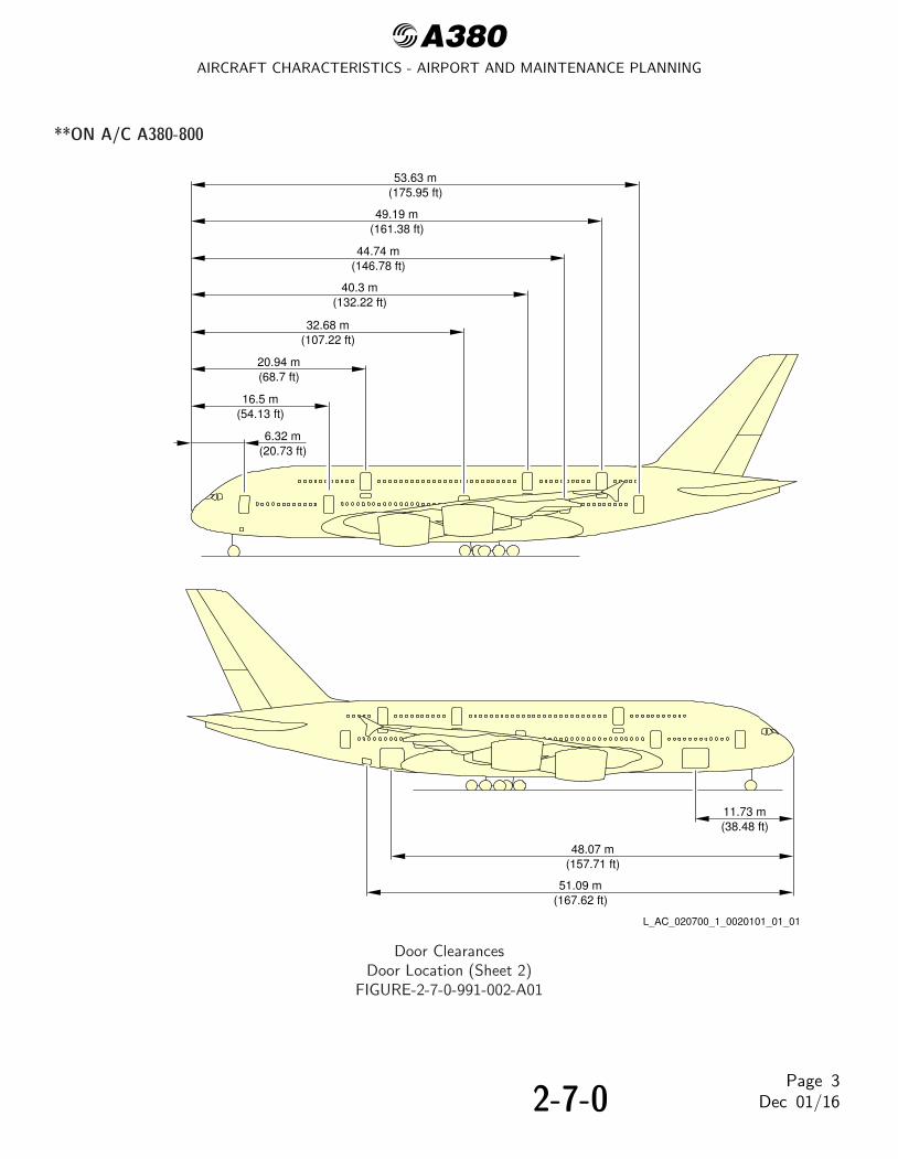
1. This section provides door clearances and location.
2-7-0Page 1
Dec 01/16

@A380AIRCRAFT CHARACTERISTICS - AIRPORT AND MAINTENANCE PLANNING
**ON A/C A380-800
FWDCARGO DOOR
AFTCARGO DOOR
BULKCARGO DOOR
DOORM2L
DOORM1L
DOORU1L
DOORU2L
DOORU3L
DOORM4L
DOORM5L
EMERGENCYEXIT DOOR
M3L
DOORU1R
DOORU2R
DOORU3R
DOORM5R DOOR
M4RDOORM2R
DOORM1R
EMERGENCYEXIT DOOR
M3R
L_AC_020700_1_0010101_01_01
Door ClearancesDoor Location (Sheet 1)
FIGURE-2-7-0-991-001-A01
2-7-0Page 2
Dec 01/16
@A380AIRCRAFT CHARACTERISTICS - AIRPORT AND MAINTENANCE PLANNING
**ON A/C A380-800
53.63 m(175.95 ft)
49.19 m(161.38 ft)
44.74 m(146.78 ft)
40.3 m(132.22 ft)
20.94 m(68.7 ft)
6.32 m(20.73 ft)
16.5 m(54.13 ft)
11.73 m(38.48 ft)
48.07 m(157.71 ft)
51.09 m(167.62 ft)
32.68 m(107.22 ft)
L_AC_020700_1_0020101_01_01
Door ClearancesDoor Location (Sheet 2)
FIGURE-2-7-0-991-002-A01
2-7-0Page 3
Dec 01/16

@A380AIRCRAFT CHARACTERISTICS - AIRPORT AND MAINTENANCE PLANNING
**ON A/C A380-800
0.04 m(0.13 ft)
1.26 m(4.13 ft)
0.04 m(0.13 ft)
2.51 m(8.23 ft)
1.07 m(3.51 ft)
0.72 m(2.36 ft)
01
0.86 m(2.82 ft)
01
FWD
0.05 m(0.16 ft)
2.13 m(6.99 ft)
1.90 m(6.23 ft)
FWD
MAIN DECK DOORSM1L, M1R
MEASURED FROM THE EXTERNAL POINT OF THE SCUFF PLATEAND THE MOST EXTERNAL POINT OF THE DOOR SKIN.
01NOTE:
SEECHAPTER
2−3
L_AC_020700_1_0050101_01_01
Door ClearancesForward Passenger Doors
FIGURE-2-7-0-991-005-A01
2-7-0Page 4
Dec 01/16

@A380AIRCRAFT CHARACTERISTICS - AIRPORT AND MAINTENANCE PLANNING
**ON A/C A380-800
1.92 m(6.30 ft)
1.90 m(6.23 ft)
SEECHAPTER
2−3
SEECHAPTER
2−3
2.13 m(6.99 ft)
0.05 m(0.16 ft)
FWD
0.08 m(0.26 ft)
2.11 m(6.92 ft)
0.89 m(2.92 ft)
ON M3L/M3R0.70 m(2.30 ft)
0.04 m(0.13 ft)
0.04 m(0.13 ft) 0.04 m
(0.13 ft)
1.02 m(3.35 ft)
ON M3L/M3R0.84 m(2.76 ft)
01
02
01
02
2.51 m(8.23 ft)
2.51 m(8.23 ft)
1.07 m(3.51 ft)
0.52 m(1.71 ft)
0.72 m(2.36 ft)
0.04 m(0.13 ft)
FWD
1.26 m(4.13 ft)
1.07 m(3.51 ft)
0101
UPPER DECK DOORSU1L, U2L, U3L, U1R, U2R, U3R
MAIN DECK DOORSM2L, M3L, M4L, M2R, M3R, M4R
MEASURED FROM THE EXTERNAL POINT OF THE SCUFF PLATEAND THE MOST EXTERNAL POINT OF THE DOOR SKIN.
01NOTE:
02 ON DOOR M3L/M3R MEASURED FROM THE EXTERNAL POINTOF THE CUTOUT IN THE BELLY FAIRING AND THE MOSTEXTERNAL POINT OF THE BELLY FAIRING FROM THE DOOR.
L_AC_020700_1_0060101_01_01
Door ClearancesMain and Upper Deck Passenger Doors
FIGURE-2-7-0-991-006-A01
2-7-0Page 5
Dec 01/16

@A380AIRCRAFT CHARACTERISTICS - AIRPORT AND MAINTENANCE PLANNING
**ON A/C A380-800
010.96 m(3.15 ft)
1.09 m(3.58 ft)
2.51 m(8.23 ft)
1.07 m(3.51 ft)
0.04 m(0.13 ft)
0.04 m(0.13 ft)
1.26 m(4.13 ft)
FWD
01
SEECHAPTER
2−3
2.13 m(6.99 ft)
0.05 m(0.16 ft)
1.90 m(6.23 ft)
FWD
MAIN DECK DOORSM5L, M5R
AND THE MOST EXTERNAL POINT OF THE DOOR SKIN.
NOTE:MEASURED FROM THE EXTERNAL POINT OF THE SCUFF PLATE01
L_AC_020700_1_0070101_01_01
Door ClearancesAft Passenger Doors
FIGURE-2-7-0-991-007-A01
2-7-0Page 6
Dec 01/16

@A380AIRCRAFT CHARACTERISTICS - AIRPORT AND MAINTENANCE PLANNING
**ON A/C A380-800
SEECHAPTER
2−3
1.75 m(5.74 ft)
6.34 m(20.80 ft)
2.12 m(6.96 ft)
3.11 m(10.20 ft)
GROUND LINE
2.09 m(6.86 ft)
A
A
A A
FWD
(9.81 ft)R 2.99 m
DEPENDING ON CG POSITION AND AIRCRAFT WEIGHT.01NOTE:
01
L_AC_020700_1_0080101_01_01
Door ClearancesForward Cargo Compartment Door
FIGURE-2-7-0-991-008-A01
2-7-0Page 7
Dec 01/16

@A380AIRCRAFT CHARACTERISTICS - AIRPORT AND MAINTENANCE PLANNING
**ON A/C A380-800
SEECHAPTER
2−3
SEECHAPTER
2−3
1.75 m(5.74 ft)
2.09 m(6.86 ft)
0.99 m(3.25 ft)
2.79 m(9.15 ft)
GROUND LINE
2.01 m(6.59 ft)
FWD
1.13 m(3.71 ft)
6.42 m(21.06 ft)
B BA A
B
B
A
A
R 3.07 m (10.07 ft) AT R 2.95 m (9..68ft) AT
FR81AFR85
R 1.40 m(4.59 ft)
DEPENDING ON CG POSITION AND AIRCRAFT WEIGHT.01NOTE:
01
L_AC_020700_1_0090101_01_01
Door ClearancesAft Cargo Compartment Doors
FIGURE-2-7-0-991-009-A01
2-7-0Page 8
Dec 01/16

@A380AIRCRAFT CHARACTERISTICS - AIRPORT AND MAINTENANCE PLANNING
**ON A/C A380-800
AIR
CR
AF
T
GROUND LINE
A
62°
2.50 m(8.20 ft)
1.36 m(4.46 ft)
R 1.89 m(6.20 ft)
AB
(3.08 ft)0.94 m
FORWARD NOSELANDING GEARDOOR
LH SHOWNRH SYMMETRICAL
DEPENDING ON CG POSITION AND AIRCRAFT WEIGHT.01NOTE:
01
L_AC_020700_1_0100101_01_01
Door ClearancesForward Nose Landing Gear Doors (Sheet 1 of 2)
FIGURE-2-7-0-991-010-A01
2-7-0Page 9
Dec 01/16

@A380AIRCRAFT CHARACTERISTICS - AIRPORT AND MAINTENANCE PLANNING
**ON A/C A380-800
0.75 mA
IRC
RA
FT
C/L
69.2°
0.50 m
R 1.89 m
B
(1.64 ft)
(6.20 ft)
(2.46 ft)
AFT NOSE LANDINGGEAR DOOR
LH SHOWNRH SYMMETRICAL
L_AC_020700_1_0100102_01_00
Door ClearancesAft Nose Landing Gear Doors (Sheet 2 of 2)
FIGURE-2-7-0-991-010-A01
2-7-0Page 10
Dec 01/16

@A380AIRCRAFT CHARACTERISTICS - AIRPORT AND MAINTENANCE PLANNING
**ON A/C A380-800
30.91 m(101.41 ft)
LH SHOWNRH SYMMETRICAL
GROUND LINE(10.60 ft)3.23 m
MAX 79°
AIR
CR
AF
T
(5.61 ft)1.71 m
4.28 m(14.04 ft)
R 2.30 m(7.55 ft)
WING−LANDING−GEARMAIN DOOR
A
(12.96 ft)3.95 m
NOTE:DEPENDING ON CG POSITION AND AIRCRAFT WEIGHT.01
01MAX. 0.25 m (0.82 ft)MIN. 0.10 m (0.33 ft)
A
L_AC_020700_1_0110101_01_00
Door ClearancesWing Landing Gears - Main Doors
FIGURE-2-7-0-991-011-A01
2-7-0Page 11
Dec 01/16

@A380AIRCRAFT CHARACTERISTICS - AIRPORT AND MAINTENANCE PLANNING
**ON A/C A380-800
(15.49 ft)4.72 m
AIR
CR
AF
TMAX. 0.35 m (1.15 ft)MIN. 0.25 m (0.82 ft)
MAX 99°
GROUND LINE
35.67 m(117.03 ft)
(16.96 ft)5.17 m
ALH SHOWN
RH SYMMETRICAL
NOTE:
(7.38 ft)2.25 m
(16.47 ft)5.02 m
BODY−LANDING−GEAROUTER DOOR
A B
DEPENDING ON CG POSITION AND AIRCRAFT WEIGHT.01
01
R 2.90 m(9.51 ft)
L_AC_020700_1_0120101_01_00
Door ClearancesBody Landing Gears - Outer Doors (Sheet 1 of 2)
FIGURE-2-7-0-991-012-A01
2-7-0Page 12
Dec 01/16

@A380AIRCRAFT CHARACTERISTICS - AIRPORT AND MAINTENANCE PLANNING
**ON A/C A380-800
(4.04 ft)1.23 m
2.25 m(7.38 ft)
GROUND LINE
LH SHOWNRH SYMMETRICAL
NOTE:
AIR
CR
AF
T
MAX. 0.95 m (3.12 ft)MIN. 0.70 m (2.30 ft)
(3.87 ft)1.18 m
MAX 94°
BODY−LANDING−GEARINNER DOOR
DEPENDING ON CG POSITION AND AIRCRAFT WEIGHT.01
01
R 1.32 m(4.33 ft)
B
L_AC_020700_1_0120102_01_00
Door ClearancesBody Landing Gears - Inner Doors (Sheet 2 of 2)
FIGURE-2-7-0-991-012-A01
2-7-0Page 13
Dec 01/16

@A380AIRCRAFT CHARACTERISTICS - AIRPORT AND MAINTENANCE PLANNING
**ON A/C A380-800
GROUND LINE
FR117FR112
NOTE:DEPENDING ON CG POSITION AND AIRCRAFT WEIGHT.01
01 MAX. 5.52 m (18.11 ft)MIN. 5.49 m (18.01 ft)
FUSELAGE DATUM LINE
01MAX. 6.66 m (21.85 ft)MIN. 6.63 m (21.75 ft)
APU DOOR
L_AC_020700_1_0130101_01_00
Door ClearancesAPU Doors
FIGURE-2-7-0-991-013-A01
2-7-0Page 14
Dec 01/16

@A380AIRCRAFT CHARACTERISTICS - AIRPORT AND MAINTENANCE PLANNING
2-8-0 Escape Slides
**ON A/C A380-800
Escape Slides
1. GeneralThis section provides the location of cabin escape facilities and related clearances.
2. Location
A. Escape facilities are provided at the following locations:
(1) Upper deck evacuation:- One slide-raft at each passenger/crew door (total six).
(2) Main deck evacuation:- One slide-raft at each passenger/crew door (total eight)- One ramp/slide for each emergency exit door (total two). The slides are housed in the
belly fairing for off-the-wing evacuation.
2-8-0Page 1
Dec 01/16

@A380AIRCRAFT CHARACTERISTICS - AIRPORT AND MAINTENANCE PLANNING
**ON A/C A380-800
MAIN DECK DUAL−LANE
COCKPIT ESCAPEROPE
SLIDE/RAFT
UPPER DECK DUAL−LANESLIDE/RAFT
OVERWING DUAL−LANERAMP/SLIDE
UPPER DECK DUAL−LANESLIDE/RAFT
MAIN DECK DUAL−LANESLIDE/RAFT
MAIN DECK DUAL−LANESLIDE/RAFT
UPPER DECK DUAL−LANESLIDE/RAFT
− THE RAMPS/SLIDES AT DOORS M3L AND M3R DO NOT HAVE RAFT CAPABILITY.
NOTE:− LH SHOWN, RH SYMMETRICAL.
L_AC_020800_1_0010101_01_02
Escape SlidesLocation
FIGURE-2-8-0-991-001-A01
2-8-0Page 2
Dec 01/16

@A380AIRCRAFT CHARACTERISTICS - AIRPORT AND MAINTENANCE PLANNING
**ON A/C A380-800
0
− 3
− 6
− 9
− 1
2
− 1
5
− 1
8
− 2
1
− 2
4
− 2
7
− 3
0
− 3
3
− 3
6
− 3
9
GR
ID E
QU
ALS
1 m
(3.
28 ft
) IN
RE
ALI
TY
− 4
2
NO
TE
:−
LH
SH
OW
N, R
H S
YM
ME
TR
ICA
L.
EM
ER
GE
NC
Y D
ES
CE
NT
TH
RO
UG
H T
HE
WIN
DO
W O
PE
NIN
G W
ITH
TH
E E
SC
AP
E R
OP
E
− D
IME
NS
ION
S A
RE
AP
PR
OX
IMA
TE
.
EM
ER
GE
NC
Y E
VA
CU
AT
ION
L_AC_020800_1_0020101_01_02
Escape SlidesDimensions
FIGURE-2-8-0-991-002-A01
2-8-0Page 3
Dec 01/16

@A380AIRCRAFT CHARACTERISTICS - AIRPORT AND MAINTENANCE PLANNING
2-9-0 Landing Gear
**ON A/C A380-800
Landing Gear
1. GeneralThe aircraft has:- Two Wing Landing Gears (WLG) with four wheel bogie assembly and related doors,- Two Body Landing Gears (BLG) with six wheel bogie assembly and related doors,- A Nose Landing Gear (NLG) with twin wheel assembly and related doors.
The wing landing gears are located under the wing and retract sideways towards the fuselagecenterline.The body landing gears are located on the belly and retract rearward into a bay in the fuselage.The nose landing gear retracts forward into a fuselage compartment below the cockpit.
The landing gear and landing gear doors operation are controlled electrically and are hydraulically andmechanically operated.In abnormal operation, the landing gear can be extended by gravity.
For landing gear footprint and tire size, refer to 07-02-00.
2. Wing Landing GearEach WLG has a leg assembly and a four-wheel bogie beam. The WLG leg includes a Bogie TrimActuator (BTA) and an oleo-pneumatic shock absorber.A two-piece sidestay assembly holds the WLG in the extended position. A lockstay keeps the sidestayassembly stable in the locked down position.
3. Body Landing GearThe two BLG have a six-wheel bogie beam and a leg assembly that includes an oleo-pneumatic shockabsorber. A two-piece dragstay assembly mechanically locks the leg in the extended position.
4. Nose Landing GearThe NLG includes a single-stage direct acting oleo-pneumatic shock absorber. A two-piece dragstayassembly with a lockstay, mechanically locks the leg in the extended position.
5. Tow Truck PowerElectric power to the navigation lights can be provided through the tow truck power connector on the24GC service panel, see FIGURE 2-9-0-991-007-A and for connector definition, see 05-04-04.
6. SteeringThe wheel steering control system has two parts:- Nose wheel Steering (NWS),- Body Wheel Steering (BWS).Steering is controlled by two hand wheels in the cockpit. For steering angle controlled by the handwheels, refer to AMM 32-51-00 (NWS) and AMM 32-54-00 (BWS).For steering angle limitation, refer to AMM 09-10-00.
2-9-0Page 1
Dec 01/16

@A380AIRCRAFT CHARACTERISTICS - AIRPORT AND MAINTENANCE PLANNING
A steering disconnection box installed on the nose landing gear to allow steering deactivation fortowing purpose.
7. Landing Gear Servicing Points
A. GeneralFilling of the landing gear shock absorbers is through MS28889 standard valves.Charging of the landing gear shock absorbers is accomplished with nitrogen through MS28889standard valves.
B. Charging PressureFor charging of the landing gear shock absorbers, refer to AMM 32-00-00.
8. Braking
A. GeneralCarbon brakes are installed on each wheel of the WLG and on the wheels of the front andcenter axles of the BLG.The braking system is electrically controlled and hydraulically operated.The braking system has four braking modes plus autobrake and anti-skid systems:- Normal braking with anti-skid capability,- Alternative braking with anti-skid capability,- Emergency Braking (with Ultimate Braking),- Emergency braking without anti-skid protection is also available as an alternative function of
the alternate braking system,- A park brake system that is manually set is available for the BLG only. This system can also
be used to supply emergency braking.
B. In-Flight Wheel BrakingBraking occurs automatically during the retraction of the landing gear. This stops the rotationof the BLG and WLG wheels (except the wheels on the aft axle of each BLG) before the landinggears go into their related bays.
9. Tire Pressure Indicating System (TPIS)The TPIS automatically monitors the tire pressures and shows these values on Built In TestEquipment (BITE) and also supplies other data and warnings on the WHEEL page of the SystemDisplay (SD).The TPIS includes Built In Test Equipment.
10. Built In Test Equipment (BITE)The BITE has these functions, it:- Continuously monitors its systems for failures,- Sends failure data (maintenance and warnings) to other systems in the aircraft,- Keeps a record of the failures,- Automatically does specified tests of the system, or part of the system, at specified times,- Lets specified tests to be done during the maintenance procedures.
2-9-0Page 2
Dec 01/16

@A380AIRCRAFT CHARACTERISTICS - AIRPORT AND MAINTENANCE PLANNING
The BITE for the following systems is described in these chapters:- The Brakes AMM 32-46-00,- The Steering AMM 32-52-00,- The TPIS AMM 32-49-00,- The Landing Gear AMM 32-69-00.
2-9-0Page 3
Dec 01/16

@A380AIRCRAFT CHARACTERISTICS - AIRPORT AND MAINTENANCE PLANNING
**ON A/C A380-800
MAIN DOOR(HYDRAULICALLY OPERATED)
AUXILIARY
HINGED DOOR
FAIRING DOOR
A
TIRE INFLATION ADAPTER(EXAMPLE)
E
A
B
WLG LEGASSEMBLY
TORQUELINKS
AFT AXLE
BRAKE RODASSEMBLY
FWDAXLE
BOGIE BEAMASSEMBLY
BOGIE TRIMACTUATOR
SLAVELINKS
SHOCKABSORBER
F
G
DOOR
D
L_AC_020900_1_0050101_01_00
Wing Landing GearGeneral (Sheet 1 of 3)
FIGURE-2-9-0-991-005-A01
2-9-0Page 4
Dec 01/16

@A380AIRCRAFT CHARACTERISTICS - AIRPORT AND MAINTENANCE PLANNING
**ON A/C A380-800
WLG DOORACTUATOR
WARNING FLAG
SAFETY COLLAR
GROUND LOCK PIN
SIDE STAYASSEMBLY
UNLOCKACTUATOR
LOCK LINK
DOWNLOCKSPRINGS
QUICK RELEASE PIN
C
C
D
B
L_AC_020900_1_0050102_01_00
Wing Landing GearSafety Devices (Sheet 2 of 3)FIGURE-2-9-0-991-005-A01
2-9-0Page 5
Dec 01/16

@A380AIRCRAFT CHARACTERISTICS - AIRPORT AND MAINTENANCE PLANNING
**ON A/C A380-800
GROUNDING (EARTHING) POINT
E CHARGE VALVE(NITROGEN)
CHECK/FILLVALVE (OIL)
SEAL CHANGEOVERVALVE (COV)
G
F
L_AC_020900_1_0050103_01_01
Wing Landing GearServicing (Sheet 3 of 3)
FIGURE-2-9-0-991-005-A01
2-9-0Page 6
Dec 01/16

@A380AIRCRAFT CHARACTERISTICS - AIRPORT AND MAINTENANCE PLANNING
**ON A/C A380-800
INNER DOOR
OUTER DOOR
BLG LEGASSEMBLY
CENTER DOORACTUATOR
DRAG BRACE ASSEMBLY
OUTER DOOR ACTUATOR
CENTER DOOR
A
B
A
(EXAMPLE)
BOGIE TRIMACTUATOR
STEERING
BRAKE ROD
BOGIE/AXLEASSEMBLY
SLAVELINKS
SHOCKABSORBER
OUTERCYLINDER
PINTLE
ACTUATOR
TORQUELINKS
TIRE INFLATIONADAPTOR
FRAME
D
J
H
G
F
G
L_AC_020900_1_0060101_01_00
Body Landing GearGeneral (Sheet 1 of 4)
FIGURE-2-9-0-991-006-A01
2-9-0Page 7
Dec 01/16

@A380AIRCRAFT CHARACTERISTICS - AIRPORT AND MAINTENANCE PLANNING
**ON A/C A380-800
C
INNER DOORACTUATOR
B
WARNINGFLAG
SAFETY COLLAR
QUICKRELEASE
PIN
C
L_AC_020900_1_0060102_01_01
Body Landing GearDoor Safety Devices (Sheet 2 of 4)
FIGURE-2-9-0-991-006-A01
2-9-0Page 8
Dec 01/16

@A380AIRCRAFT CHARACTERISTICS - AIRPORT AND MAINTENANCE PLANNING
**ON A/C A380-800
WARNINGFLAG
SAFETY STRUT
SAFETY COLLAR
E
QUICKRELEASE
PIN
QUICKRELEASE
PIN
QUICKRELEASE
PIN
LOCKINGPIN
SOLIDPIN
ATTACHMENT PIN
ATTACHMENT PIN
LOCKINGPIN
BLG OUTERDOOR ACTUATOR
CENTER DOORFITTING
E
D
L_AC_020900_1_0060103_01_00
Body Landing GearDoor Safety Devices (Sheet 3 of 4)
FIGURE-2-9-0-991-006-A01
2-9-0Page 9
Dec 01/16

@A380AIRCRAFT CHARACTERISTICS - AIRPORT AND MAINTENANCE PLANNING
**ON A/C A380-800
CHARGING VALVE(NITROGEN)
DRAINVALVE
SEAL CHANGEOVERVALVE (COV)
TYPICAL
F
LOCK SPRINGS
LOCK LINKS
H J
GGROUNDING(EARTHING)
POINT
GROUNDLOCK PIN
WARNINGFLAG
L_AC_020900_1_0060104_01_01
Body Landing GearServicing and Safety Device (Sheet 4 of 4)
FIGURE-2-9-0-991-006-A01
2-9-0Page 10
Dec 01/16

@A380AIRCRAFT CHARACTERISTICS - AIRPORT AND MAINTENANCE PLANNING
**ON A/C A380-800
B
TOWINGADAPTER
NWSACTUATOR
DOORACTUATOR
FORWARDDOOR
REARDOOR
STEERINGMECHANISM
JACKINGPOINT
MAINTENANCESERVICE PANEL
STEERINGDISCONNECT
PANEL
TIRE INFLATIONADAPTER
A
SHOCKABSORBER
AXLE
TORQUELINKS
MAIN FITTING
C
A
J
E
RETRACTIONACTUATOR
DRAG STAY ASSEMBLY
L
H
L_AC_020900_1_0070101_01_00
Nose Landing GearGeneral (Sheet 1 of 4)
FIGURE-2-9-0-991-007-A01
2-9-0Page 11
Dec 01/16

@A380AIRCRAFT CHARACTERISTICS - AIRPORT AND MAINTENANCE PLANNING
**ON A/C A380-800
D NLG DOORACTUATOR
B
C
LOCK STAY
SAFETY COLLAR
QUICKRELEASE PIN
D
UNLOCKACTUATOR
GROUNDLOCK PIN
WARNINGFLAG
WARNINGFLAG
L_AC_020900_1_0070102_01_01
Nose Landing GearSafety Devices (Sheet 2 of 4)FIGURE-2-9-0-991-007-A01
2-9-0Page 12
Dec 01/16

@A380AIRCRAFT CHARACTERISTICS - AIRPORT AND MAINTENANCE PLANNING
**ON A/C A380-800
FG
GROUND TOWING SWITCH
SAFETY PIN
F G
STEERING DISCONNECT PANEL24GC
E
TOW TRUCK POWER CONNECTORFOR PIN ALLOCATIONSEE 05−04−04
L_AC_020900_1_0070103_01_01
Nose Landing GearSteering Disconnect Panel (Sheet 3 of 4)
FIGURE-2-9-0-991-007-A01
2-9-0Page 13
Dec 01/16

@A380AIRCRAFT CHARACTERISTICS - AIRPORT AND MAINTENANCE PLANNING
**ON A/C A380-800
CHARGE VALVE(NITROGEN)
SEAL CHANGEOVERVALVE (COV)
DRAIN VALVE
GROUNDING(EARTHING) POINT
J
L
H
K
K
L_AC_020900_1_0070104_01_01
Nose Landing GearServicing (Sheet 4 of 4)
FIGURE-2-9-0-991-007-A01
2-9-0Page 14
Dec 01/16

@A380AIRCRAFT CHARACTERISTICS - AIRPORT AND MAINTENANCE PLANNING
**ON A/C A380-800
Landing Gear Maintenance Pits
1. General
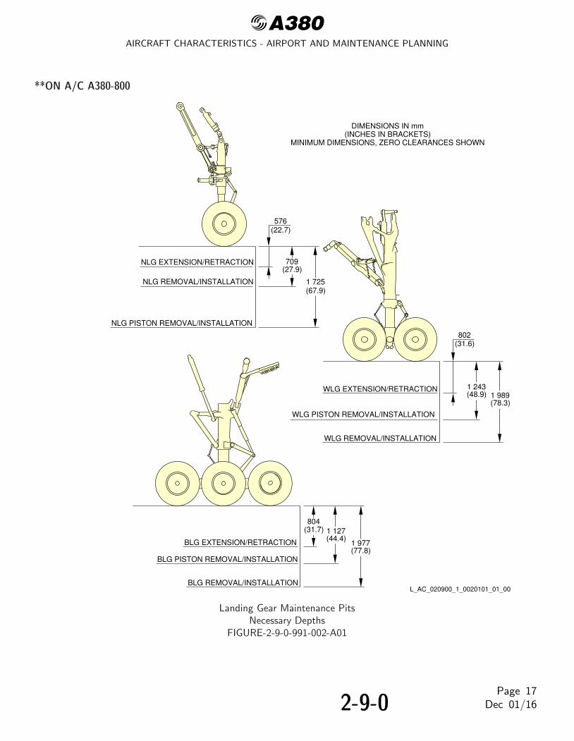
The minimum maintenance pit envelopes for the landing gear shock absorber maintenance are shownin FIGURE 2-9-0-991-001-A, FIGURE 2-9-0-991-002-A, FIGURE 2-9-0-991-003-A and FIGURE2-9-0-991-004-A.The three envelopes show the minimum dimensions for these maintenance operations:- Extension and retraction- Gear removal- Piston removal.
All dimensions shown are minimum dimensions with zero clearances. The dimensions for the pits havebeen determined as follows:- The length and width of the pits allow the gear to rotate as the weight is taken off the landing
gear- The landing gear is in the maximum grown condition- The WLG and BLG bogie beams are removed before the piston is removed- The NLG wheels are removed before the piston is removed- All pistons are removed vertically.
Dimensions for elevators and associated mechanisms must be added to those in FIGURE2-9-0-991-001-A, FIGURE 2-9-0-991-002-A, FIGURE 2-9-0-991-003-A and FIGURE 2-9-0-991-004-A.
A. ElevatorsThese can be either mechanical or hydraulic. They are used to:- Permit easy movement of persons and equipment around the landing gears- Lift and remove landing gear assemblies out of the pits.
B. JackingThe aircraft must be in position over the pits to put the gear on the elevators. Jacks must beinstalled and engaged with all the jacking points, Ref. 02-14-00 for aircraft maintenance jacking.Jacks must support the total aircraft weight, i.e. when the landing gears do not touch theelevators on retraction/extension tests.When tripod support jacks are used the tripod-base circle radius must be limited because thelocations required for positioning the columns are close to the sides of the pits.
2-9-0Page 15
Dec 01/16

@A380AIRCRAFT CHARACTERISTICS - AIRPORT AND MAINTENANCE PLANNING
**ON A/C A380-800
2 59
8
(102
.3)
5 62
5.5
(221
.5)
1 66
3(6
5.5)
FRONT OF NOSE RADOME
1 52
6(6
0.1) 76
3(3
0)
NLG
EX
TE
NS
ION
/RE
TR
AC
TIO
N P
IT O
UT
LIN
E
FW
D J
AC
KIN
G P
OIN
T
AIR
CR
AF
T C
EN
TE
R L
INE
WLG
RE
MO
VA
L P
IT O
UT
LIN
E
WLG
PIS
TO
N R
EM
OV
AL
PIT
OU
TLI
NE
WIN
G J
AC
KIN
G P
OIN
T
BLG
RE
MO
VA
L P
IT O
UT
LIN
E
BLG
EX
TE
NS
ION
/RE
TR
AC
TIO
N
BLG
PIS
TO
N R
EM
OV
AL
PIT
OU
TLI
NE
DIM
EN
SIO
NS
IN m
m(I
NC
HE
S IN
BR
AC
KE
TS
)M
INIM
UM
DIM
EN
SIO
NS
, ZE
RO
CLE
AR
AN
CE
S S
HO
WN
33 6
59(1
325
.2)
LH S
HO
WN
RH
SY
MM
ET
RIC
AL
4 50
6(1
77.4
)
PIT
OU
TLI
NE
WLG
EX
TE
NS
ION
/RE
TR
AC
TIO
NP
IT O
UT
LIN
E
L_AC_020900_1_0010101_01_00
Landing Gear Maintenance PitsMaintenance Pit EnvelopesFIGURE-2-9-0-991-001-A01
2-9-0Page 16
Dec 01/16
@A380AIRCRAFT CHARACTERISTICS - AIRPORT AND MAINTENANCE PLANNING
**ON A/C A380-800
NLG EXTENSION/RETRACTION
NLG REMOVAL/INSTALLATION
NLG PISTON REMOVAL/INSTALLATION
WLG EXTENSION/RETRACTION
WLG PISTON REMOVAL/INSTALLATION
WLG REMOVAL/INSTALLATION
BLG REMOVAL/INSTALLATION
BLG PISTON REMOVAL/INSTALLATION
BLG EXTENSION/RETRACTION
DIMENSIONS IN mm(INCHES IN BRACKETS)
MINIMUM DIMENSIONS, ZERO CLEARANCES SHOWN
576(22.7)
709(27.9)
1 725(67.9)
802(31.6)
1 243(48.9) 1 989
(78.3)
804(31.7) 1 127
(44.4)1 977(77.8)
L_AC_020900_1_0020101_01_00
Landing Gear Maintenance PitsNecessary Depths
FIGURE-2-9-0-991-002-A01
2-9-0Page 17
Dec 01/16

@A380AIRCRAFT CHARACTERISTICS - AIRPORT AND MAINTENANCE PLANNING
**ON A/C A380-800
972
(38.
3)3
158
(124
.3)
3 71
1(1
46.1
)
7 13
4(2
80.9
)
4 12
6(1
62.4
)1
929
(75.
9)
WLG
EX
TE
NS
ION
/RE
TR
AC
TIO
NP
IT O
UT
LIN
E
WLG
RE
MO
VA
LP
IT O
UT
LIN
E
BLG
RE
MO
VA
L P
IT O
UT
LIN
E
AIR
CR
AF
T C
EN
TE
R L
INE
DIM
EN
SIO
NS
IN m
m(I
NC
HE
S IN
BR
AC
KE
TS
)M
INIM
UM
DIM
EN
SIO
NS
, ZE
RO
CLE
AR
AN
CE
S S
HO
WN
WLG
PIS
TO
N R
EM
OV
AL
PIT
OU
TLI
NE
(101
.8)
2 58
5
3 56
0(1
40.2
)
6 22
8(2
45.2
)
1 06
7(4
2)
(37.
5)95
2
(93.
2)2
368
1 49
0(5
8.7)
(109
.9)
2 79
1
(20.
2)51
3
L_AC_020900_1_0030101_01_00
Landing Gear Maintenance PitsMaintenance Pit Envelopes - WLG Pit Dimensions
FIGURE-2-9-0-991-003-A01
2-9-0Page 18
Dec 01/16

@A380AIRCRAFT CHARACTERISTICS - AIRPORT AND MAINTENANCE PLANNING
**ON A/C A380-800
AIR
CR
AF
T C
EN
TE
R L
INE
1 68
0(6
6.1)
DIM
EN
SIO
NS
IN m
m(I
NC
HE
S IN
BR
AC
KE
TS
)M
INIM
UM
DIM
EN
SIO
NS
, ZE
RO
CLE
AR
AN
CE
S S
HO
WN
133
(5.2
)
3 18
8(1
25.5
)
7 13
4(2
80.9
)
BLG
PIS
TO
N R
EM
OV
AL
BLG
RE
MO
VA
LP
IT O
UT
LIN
E
WLG
RE
MO
VA
L P
IT O
UT
LIN
E
PIT
OU
TLI
NE
4 85
6(1
91.2
)
BLG
EX
TE
NS
ION
/RE
TR
AC
TIO
NP
IT O
UT
LIN
E
2 63
2(1
03.6
)
1 16
8(4
6)
1 05
2(4
1.4)
2 10
5(8
2.9)
1 49
0(5
8.7)
WLG
EX
TE
NS
ION
/RE
TR
AC
TIO
N P
IT O
UT
LIN
E
L_AC_020900_1_0040101_01_00
Landing Gear Maintenance PitsMaintenance Pit Envelopes - BLG Pit Dimensions
FIGURE-2-9-0-991-004-A01
2-9-0Page 19
Dec 01/16
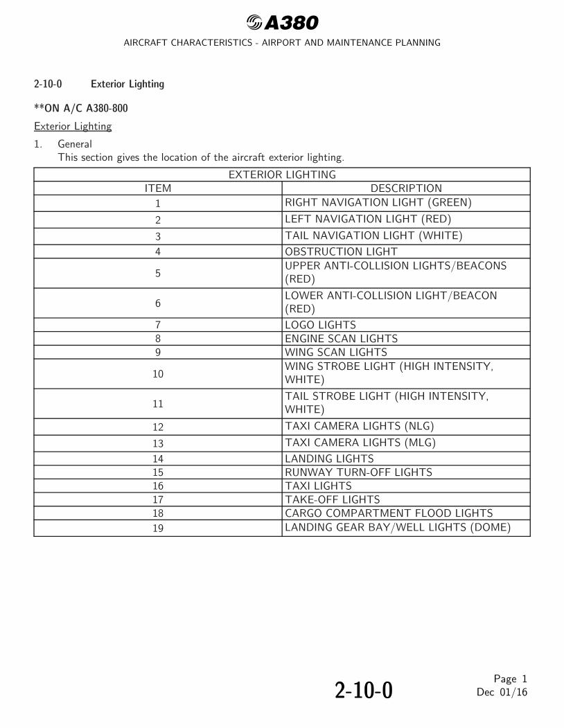
@A380AIRCRAFT CHARACTERISTICS - AIRPORT AND MAINTENANCE PLANNING
2-10-0 Exterior Lighting
**ON A/C A380-800
Exterior Lighting
1. GeneralThis section gives the location of the aircraft exterior lighting.
EXTERIOR LIGHTINGITEM DESCRIPTION
1 RIGHT NAVIGATION LIGHT (GREEN)
2 LEFT NAVIGATION LIGHT (RED)
3 TAIL NAVIGATION LIGHT (WHITE)
4 OBSTRUCTION LIGHT
5UPPER ANTI-COLLISION LIGHTS/BEACONS(RED)
6LOWER ANTI-COLLISION LIGHT/BEACON(RED)
7 LOGO LIGHTS8 ENGINE SCAN LIGHTS9 WING SCAN LIGHTS
10WING STROBE LIGHT (HIGH INTENSITY,WHITE)
11TAIL STROBE LIGHT (HIGH INTENSITY,WHITE)
12 TAXI CAMERA LIGHTS (NLG)
13 TAXI CAMERA LIGHTS (MLG)
14 LANDING LIGHTS15 RUNWAY TURN-OFF LIGHTS16 TAXI LIGHTS17 TAKE-OFF LIGHTS18 CARGO COMPARTMENT FLOOD LIGHTS
19 LANDING GEAR BAY/WELL LIGHTS (DOME)
2-10-0Page 1
Dec 01/16

@A380AIRCRAFT CHARACTERISTICS - AIRPORT AND MAINTENANCE PLANNING
**ON A/C A380-800
RH
LH
11
3
2
1
10 4
7
5
8 9
13
12
6
L_AC_021000_1_0070101_01_00
Exterior LightingFIGURE-2-10-0-991-007-A01
2-10-0Page 2
Dec 01/16

@A380AIRCRAFT CHARACTERISTICS - AIRPORT AND MAINTENANCE PLANNING
**ON A/C A380-800
17 15
14
16
L_AC_021000_1_0080101_01_00
Exterior LightingFIGURE-2-10-0-991-008-A01
2-10-0Page 3
Dec 01/16

@A380AIRCRAFT CHARACTERISTICS - AIRPORT AND MAINTENANCE PLANNING
**ON A/C A380-800
2
15 15
3
1
17
88
L_AC_021000_1_0090101_01_00
Exterior LightingFIGURE-2-10-0-991-009-A01
2-10-0Page 4
Dec 01/16

@A380AIRCRAFT CHARACTERISTICS - AIRPORT AND MAINTENANCE PLANNING
**ON A/C A380-800
11
1010
16
14
5 5 6
16
9 9
14
L_AC_021000_1_0100101_01_00
Exterior LightingFIGURE-2-10-0-991-010-A01
2-10-0Page 5
Dec 01/16

@A380AIRCRAFT CHARACTERISTICS - AIRPORT AND MAINTENANCE PLANNING
**ON A/C A380-800
19 191818
EXAMPLE FOR LIGHT N° 18
CEILING LIGHT
SPOT LIGHT
GROUND
7
7
L_AC_021000_1_0110101_01_00
Exterior LightingFIGURE-2-10-0-991-011-A01
2-10-0Page 6
Dec 01/16

@A380AIRCRAFT CHARACTERISTICS - AIRPORT AND MAINTENANCE PLANNING
2-11-0 Antennas and Probes Location
**ON A/C A380-800
Antennas and Probes Location
1. This section gives the location of antennas and probes.
2-11-0Page 1
Dec 01/16

@A380AIRCRAFT CHARACTERISTICS - AIRPORT AND MAINTENANCE PLANNING
**ON A/C A380-800
VHF(1)ELTVHF(3)
ADF(2)
ADF(1)
SATCOM(1)
TCAS TOP(2)
TCAS TOP(1)
GPS(1)
GPS(2)
MFP(1)
ISP(1−1)
ISP(3−1)
ISP(2−1) RADIO ALTIMETRE(1)
RADIO ALTIMETRE(2)
RADIO ALTIMETRE(3)
HF
VHF(2)MARKER
VOR
MFP(3)
ISP(2−2)
ISP(1−2)
MFP(2)
STBY STATIC PROBE(2)
TCAS BOTTOM(2)
DME(1) BOTTOM
TCAS BOTTOM(1)
DME(2) BOTTOM
ISP(3−2)
WEATHER RADAR
ICE DETECTOR PROBE RH
SSA(2/3)
SSA(1)
GLIDE TRACK
STBY STATIC PROBE(1)STBY PITOT
LOCGLIDE CAPTURE
ICE DETECTOR PROBE LH
L_AC_021100_1_0010101_01_00
Antennas and ProbesLocation
FIGURE-2-11-0-991-001-A01
2-11-0Page 2
Dec 01/16

@A380AIRCRAFT CHARACTERISTICS - AIRPORT AND MAINTENANCE PLANNING
2-12-0 Power Plant
**ON A/C A380-800
Auxiliary Power Unit
1. General- The APU is installed in the tail cone, at the rear part of the fuselage (Section 19.1), inside a
fireproof compartment (between frames 112 and 117).- The Air Intake System is located on top of the APU and crosses the space between the APU
plenum chamber and the aircraft outside (upper right side position). The Air Intake Housing islocated between frames 111 and 113 and the Air Intake Duct is located in the space betweenframes 113 and 115.
- The Exhaust Muffler is located at the end of the tail cone, aligned with the APU and crossesthree different zones, from frame 116 to the rear fairing.
- The Electronic Control Box (ECB) is installed in an electronic cooled rack, closed to frame 95,within the pressurized fuselage.
2. Controls and IndicationPrimary APU controls and indications are installed in the cockpit, mainly in the overhead panel,center pedestal panel and forward center panel. Additionally, two external emergency shutoff controlsare installed on the Nose Landing Gear panel and on the Refuel/Defuel panel.
2-12-0Page 1
Dec 01/16

@A380AIRCRAFT CHARACTERISTICS - AIRPORT AND MAINTENANCE PLANNING
**ON A/C A380-800
THE DISTANCE FROM FR94, FR98, FR100 BOTTOMCENTERLINE TO FUSELAGE DATUM (FD) AS FOLLOWS:
NOTE:
FR117/
FR112/
FR110/
A
STA72320
STA72922
STA75622
317AB
315AL
313AB
313AZ
FR112 TO FD = 974.9 mm (38.38 in)FR117 TO FD = 1 772.4 mm (69.78 in)FR120 TO FD = 2 239.8 mm (88.18 in).
A B
315BL
315AR
Z310
L_AC_021200_1_0010101_01_00
Auxiliary Power UnitAccess Doors
FIGURE-2-12-0-991-001-A01
2-12-0Page 2
Dec 01/16
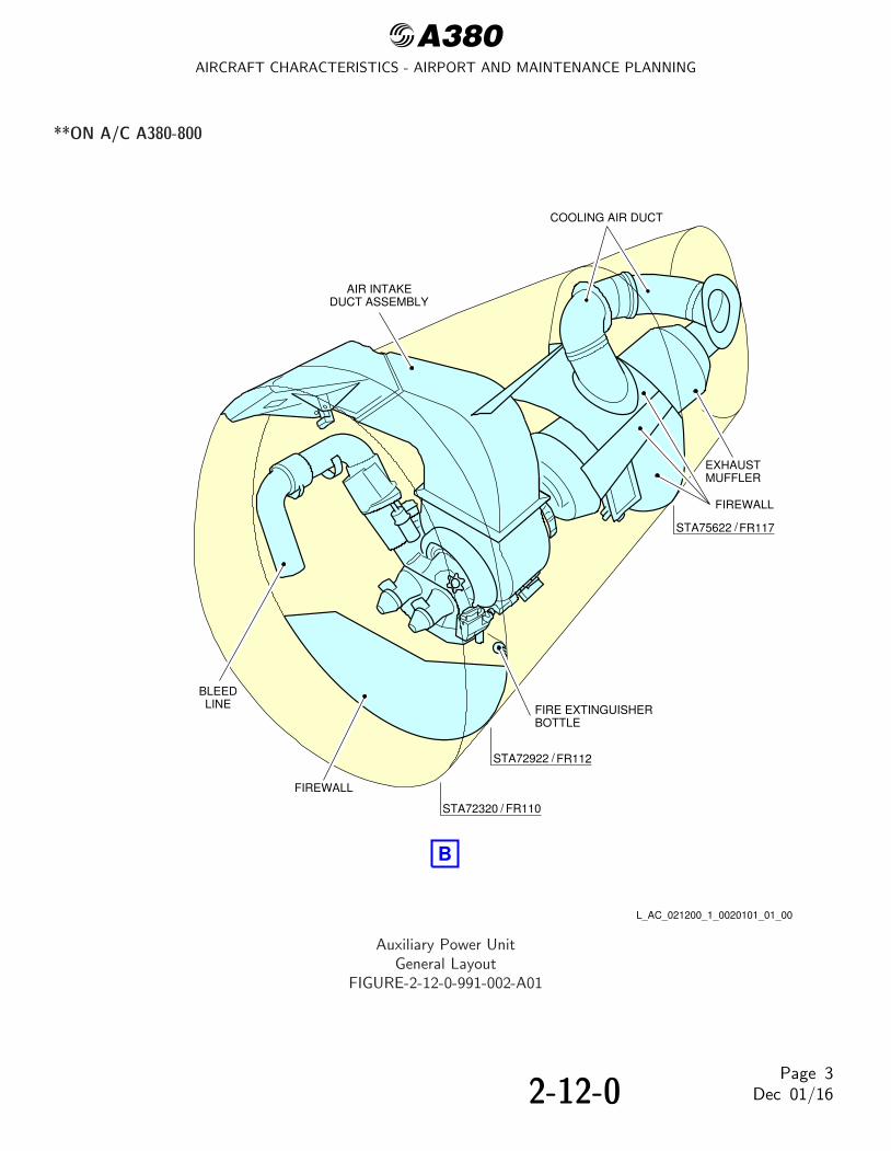
@A380AIRCRAFT CHARACTERISTICS - AIRPORT AND MAINTENANCE PLANNING
**ON A/C A380-800
EXHAUSTMUFFLER
FIREWALL
FIRE EXTINGUISHERBOTTLE
FIREWALL
AIR INTAKEDUCT ASSEMBLY
COOLING AIR DUCT
BLEEDLINE
FR112/
FR117/
FR110/
STA72922
STA72320
STA75622
B
L_AC_021200_1_0020101_01_00
Auxiliary Power UnitGeneral Layout
FIGURE-2-12-0-991-002-A01
2-12-0Page 3
Dec 01/16

@A380AIRCRAFT CHARACTERISTICS - AIRPORT AND MAINTENANCE PLANNING
**ON A/C A380-800
Engine and Nacelle
1. Engine and Nacelle - GP 7200 Engine
A. EngineThe engine is a high by-pass ratio, two-rotor, axial flow turbofan engine with a highcompression ratio. The Engine has Four Major Sections as Follows:- compressor section- combustion section- turbine section- accessory drive section.The compressor section supplies High Pressure (HP) compressed air to the diffuser/burner forcore engine thrust, aircraft service bleed systems, and by-pass air for thrust. A five-stage LowPressure (LP) compressor rotor assembly is located to the rear of the fan rotor. An acousticsplitter fairing directs the primary airstream into the nine-stage HP compressor rotor assembly.The HP compressor has three stages of variable Inlet Guide Vanes (IGVs) and external bleedsfrom stages four, seven, and nine, with an internal bleed from stage six.The combustion section receives compressed heated air from the HP compressor and fuel fromthe fuel nozzles. The mixture of hot air and fuel is ignited and burned in the single-annularcombustion chamber to generate a HP stream of hot gas to turn the HP turbine and LPturbine.The turbine section consists of HP turbine and LP turbine. The two-stage HP turbine rotorassembly receives the hot gas from the diffuser/burner. The HP turbine supplies the power toturn the HP compressor. The six-stage LP turbine has an active clearance control system formore efficient engine operation. The LP turbine provides the power to turn the LP compressorand fan rotor. The Turbine Exhaust Case (TEC) assembly supplies the structural support for therear of the engine. The TEC straightens the exhaust gas flow as it exits the engine.The accessory drive section consists of Main Gearbox (MGB) and Angle Gearbox (AGB). TheMGB supplies the power to turn the attached engine and aircraft accessories. The AGBtransmits the power from the engine rotor to the MGB. During engine start, the AGB transmitsthe power from the MGB to turn the engine rotor.The LP rotor system is independent of the HP rotor system. The LP rotor system consists ofthe LP compressor and the LP turbine. The HP rotor system consists of the HP compressor andthe HP turbine.
B. NacelleThe Nacelle gives an aerodynamic shape to the engine and supports the thrust reverser system.Each engine is housed in a nacelle suspended from a pylon attached below the wing.The nacelle consists of the following major components:
(1) Air Intake Cowl AssemblyThe air intake cowl is an interchangeable aerodynamic cowl installed on the forward faceof the engine fan case with bolts. It is designed to provide contour for airflow entering theengine and attenuates the fan noise.
2-12-0Page 4
Dec 01/16

@A380AIRCRAFT CHARACTERISTICS - AIRPORT AND MAINTENANCE PLANNING
(2) Fan Cowl AssemblyThe fan-cowl doors are an assembly of aerodynamic cowls attached to the aircraft pylonstructure through its hinges. It is installed between the air intake cowl and the fan exhaustcowl/thrust reverser, around the engine fan case. It is composed of two semicircularpanels, the left and the right fan cowl door.
(3) Thrust ReverserThe thrust reverser assembly is installed at the aft part of the nacelle. The thrust reversercowls are installed on the aircraft inboard engines. It is attached to the wing pylon byhinges. The thrust reverser assembly is a standard fixed cascade, translating cowl andblocker door type thrust reverser. It is only installed on the aircraft inboard positionnacelles. It is made of two halves that make a duct around the engine. Each half consistsof a fixed structure, which gives support for the cascades and actuation system and atranslating cowl.The thrust reverser assembly encloses the engine core with an aerodynamic flow path anduses the outer translating cowl to give a fan exhaust duct and nozzle exit.In stow mode, the thrust reverser is an aerodynamic structure that adds to the enginethrust generation.In reverse mode, it is used to turn and direct the fan exhaust air in the forward directionusing blocker door through the cascades. The thrust reverser increases the aircraft brakingfunction in order to reduce the landing or aborted take-off distance, especially on acontaminated runway.
(4) Fan Exhaust Cowl AssemblyThe fan exhaust cowls is a component of the aircraft propulsion system nacelle. It isinstalled at the aft part of the nacelle. The fan exhaust cowls are installed on the aircraftoutboard engines.The fan exhaust cowls are attached to the wing pylon by hinges. The two halves of the fanexhaust cowl close the engine core with an aerodynamic flow path.The fan exhaust structure has two half-cowls hinged at the top to the wing pylon andlatched together at the bottom centerline. Its forward end is secured on the aft of the fancase and aft of the intermediate engine case.
(5) Exhaust SystemThe primary air flow is the part of the air absorbed by the engine that enters into theengine combustor and that is exhausted to atmosphere through the turbine exhaustsystem.The turbine exhaust flow path is formed by the inner wall of the exhaust nozzle and theouter wall of the exhaust plug.The secondary air flow is the part of the air absorbed by the fan that bypasses the coreengine and flows through the thrust reverser and fan exhaust cowl directly to theatmosphere.
2-12-0Page 5
Dec 01/16

@A380AIRCRAFT CHARACTERISTICS - AIRPORT AND MAINTENANCE PLANNING
2. Engine and Nacelle -TRENT 900 Engine
A. EngineThe RB211-TRENT 900 engine is a high by-pass ratio, triple spool turbo-fan.The principal modules of the engine are:- Low Pressure Compressor (LPC) rotor- Intermediate Pressure (IP) compressor- Intermediate case- HP system (this includes the High Pressure Compressor (HPC), the combustion system and
the High Pressure Turbine (HPT))- IP turbine- external gearbox- LPC case- Low Pressure Turbine (LPT)The Intermediate Pressure (IP) and Low Pressure Compressor (LPC)/Low Pressure Turbine(LPT) assemblies turn in a counter clockwise direction and the High Pressure Compressor(HPC)/ High Pressure Turbine (HPT) assembly turns in a clockwise direction (when seen fromthe rear of the engine) during engine operation.The compressors increase the pressure of the air, which flows through the engine. The necessarypower to turn the compressors is supplied by turbines.The LP system has a one-stage compressor installed at the front of the engine. A shaft connectsthe single-stage LPC to a five-stage axial flow turbine at the rear of the gas generator. The gasgenerator also includes an eight-stage IP compressor, a six-stage HPC and a combustion system.Each of the compressors in the gas generator is connected to, and turned by, a different turbine.Between the HPC and the HPT is the annular combustion system which burns a mixture of fueland air to supply energy as heat. Behind the LPT there is a collector nozzle assembly throughwhich the hot gas exhaust flows.
B. NacelleA nacelle gives the engine an aerodynamic shape and supports the thrust reverser system. Eachengine is housed in a nacelle suspended from a pylon attached below the wing.The nacelle consists of the following major components:
(1) Air Intake Cowl AssemblyThe air intake cowl is an interchangeable aerodynamic cowl installed at the front of theengine. It ducts the airflow to the fan and the engine core. The cowl has panels for easyaccess to the components. Acoustic materials are used in the manufacture of the cowl tohelp decrease the engine noise.
(2) Fan Cowl AssemblyThe fan cowl assembly has two semicircular panels, the left fan cowl door and the rightfan cowl door. The installation of the fan cowl doors is around the engine fan casebetween the air intake cowl and the thrust reverser cowl.
2-12-0Page 6
Dec 01/16

@A380AIRCRAFT CHARACTERISTICS - AIRPORT AND MAINTENANCE PLANNING
The fan Cowl Opening System (COS) have two electrical actuators which open or closethe fan cowls. Personnel operate the actuators from the ground only during enginemaintenance operations. The personnel use a switch box located on the air intake cowl.
(3) Thrust ReverserThe thrust reverser assembly is installed at the aft part of the nacelle. The thrust reversersare installed on the aircraft inboard engines. It is attached to the wing pylon by hinges.The thrust reverser assembly is a standard fixed cascade, translating cowl and blocker doortype thrust-reverser. It is only installed on the aircraft inboard engine nacelles. It is madeof two halves that make a duct around the engine. Each half has a fixed structure thatholds the cascades, the actuation system and a translating cowl.The thrust reverser assembly closes the engine core with an aerodynamic flow path anduses the outer translating cowl to make a fan exhaust duct and nozzle exit.In stow mode, the thrust reverser is an aerodynamic structure that makes the enginethrust.In reverse mode, it changes the direction of the fan exhaust air in the forward direction byuse of the blocker doors through the cascades. The thrust reverser increases the aircraftbraking and speed braking function in order to decrease the landing or aborted take-offdistance, especially on a dirty runway.
(4) Fan Exhaust Cowl AssemblyThe fan exhaust cowl is a component of the aircraft engine nacelle. It is installed at the aftpart of the nacelle. The fan exhaust structures are installed on the aircraft outboardengines. They are attached to the wing pylon by hinges. The left and right fan exhauststructures closed the engine core with an aerodynamic flow path. The structure gives a fireprotection and a support for the aerodynamic, inertial and engine loads.The fan exhaust structure has left and right cowls hinged at the top to the wing pylon andlatched together at the bottom centerline. Its forward end is attached at the aft of the fancase.
(5) Exhaust SystemPrimary air is the part of the air absorbed by the fan that enters the engine near the fanblade platform, continues through the Low Pressure (LP) and High Pressure (HP)compressors, the combustor, and the HP and LP turbines, and is accelerated andexhausted to the atmosphere through the turbine exhaust system.The turbine exhaust flow path is formed by the inner surface of the exhaust nozzle and theouter surface of the exhaust plug.Secondary air is the part of the air absorbed by the fan that is directly discharged from theouter portion of the fan, by-passes the core engine and flows through the fan exhaust tothe atmosphere.
2-12-0Page 7
Dec 01/16

@A380AIRCRAFT CHARACTERISTICS - AIRPORT AND MAINTENANCE PLANNING
**ON A/C A380-800
3.15 m(10.33 ft)
LPTURBINE
HP COMPRESSOR
COMBUSTORSECTION
2.77 m(9.09 ft)
4.72 m(15.49 ft)
4.93 m(16.17 ft)
TURBINEEXHAUST
CASE
ANGLEGEARBOX
MAINGEARBOX
DRIVE SECTIONACCESSORY
TURBINECENTER FRAME
HPTURBINE
A
A
LP COMPRESSOR
1.93 m(6.33 ft)
L_AC_021200_1_0030101_01_00
Power Plant HandlingEngine Dimensions - GP 7200 Engine
FIGURE-2-12-0-991-003-A01
2-12-0Page 8
Dec 01/16

@A380AIRCRAFT CHARACTERISTICS - AIRPORT AND MAINTENANCE PLANNING
**ON A/C A380-800
NOSECOWL
INBOARD POSITION
OUTBOARD POSITION
3.8 m(12.47 ft)
A
1.5 m(4.92 ft)
PLUG
PRIMARY NOZZLE
THRUST REVERSERFAN COWL
2.18 m(7.15 ft)
2.52 m(8.27 ft)
1.17 m(3.84 ft)
2.33 m(7.64 ft)
1.31 m(4.3 ft)
A
3.9 m(12.8 ft)
2.11 m(6.92 ft)
L_AC_021200_1_0040101_01_00
Power Plant HandlingNacelle Dimensions - GP 7200 Engine
FIGURE-2-12-0-991-004-A01
2-12-0Page 9
Dec 01/16

@A380AIRCRAFT CHARACTERISTICS - AIRPORT AND MAINTENANCE PLANNING
**ON A/C A380-800
45° C
B
ALL ENGINES
6.8 m(22.31 ft)45°
A
MIN. MAX.
A
ENGINE 1−4
2.64 m(8.66 ft)
B
3.14 m(10.3 ft)
MIN. MAX.
ENGINE 2−3
1.86 m(6.1 ft)
2.16 m(7.09 ft)
C
SEE AC SECTION2−3−0
NOTE:
: FAN COWL
1 1
B AND C DEPENDING ON AIRCRAFT CONFIGURATION.
1
A
A
AA
A
POSITIONOPEN
L_AC_021200_1_0050101_01_00
Power Plant HandlingFan Cowls - GP 7200 EngineFIGURE-2-12-0-991-005-A01
2-12-0Page 10
Dec 01/16

@A380AIRCRAFT CHARACTERISTICS - AIRPORT AND MAINTENANCE PLANNING
**ON A/C A380-800
6.32 m(20.73 ft)45°
AMIN. MAX.
1.86 m(6.1 ft)
B
2.16 m(7.09 ft)
SEE AC SECTION2−3−0
NOTE:
5.8 m(19.03 ft)35°
1.52 m(4.99 ft)
1.82 m(5.97 ft)
C
: THRUST REVERSER1
B AND C DEPENDING ON AIRCRAFT CONFIGURATION.
45°35°C
BC
B
A A11
1 1
A
A
A
POSITIONOPEN
L_AC_021200_1_0060101_01_00
Power Plant HandlingThrust Reverser Cowls - GP 7200 Engine
FIGURE-2-12-0-991-006-A01
2-12-0Page 11
Dec 01/16

@A380AIRCRAFT CHARACTERISTICS - AIRPORT AND MAINTENANCE PLANNING
**ON A/C A380-800
NOTE: B AND C DEPENDING ON AIRCRAFT CONFIGURATION.
6.32 m(20.73 ft)
AMIN. MAX.
2.64 m(8.66 ft)
3.14 m(10.3 ft)
SEE AC SECTION2−3−0
5.8 m(19.03 ft)
2.3 m(7.55 ft)
2.8 m(9.19 ft)
CB
: FAN EXHAUST COWL
45°35°C
BC
B
A A
A
A
A
1 11 1
1
45°
35°
POSITIONOPEN
L_AC_021200_1_0070101_01_01
Power Plant HandlingFan Exhaust Cowls - GP 7200 Engine
FIGURE-2-12-0-991-007-A01
2-12-0Page 12
Dec 01/16

@A380AIRCRAFT CHARACTERISTICS - AIRPORT AND MAINTENANCE PLANNING
**ON A/C A380-800
1.88 m(6.17 ft)
5.14 m(16.86 ft)
1.5 m(4.92 ft)
(2.59 ft)
8.07 m(26.48 ft)
IP COMPRESSOR
SECTIONCOMBUSTOR
IP TURBINE
HP TURBINE
HP COMPRESSOR
ACCESSORY DRIVE SECTION
1.66 m(5.45 ft)
PLUG
3.11 m(10.2 ft)
LP COMPRESSOR
0.79 m
LP TURBINE
NOZZLETURBINE EXHAUST
1.84 m(6.04 ft)
A
A
L_AC_021200_1_0080101_01_00
Power Plant HandlingEngine Dimensions - TRENT 900 Engine
FIGURE-2-12-0-991-008-A01
2-12-0Page 13
Dec 01/16

@A380AIRCRAFT CHARACTERISTICS - AIRPORT AND MAINTENANCE PLANNING
**ON A/C A380-800
INBOARD
OUTBOARD
INSTALLATION
INSTALLATION
PLUG
PRIMARY NOZZLE
THRUST REVERSER
FAN COWL
NOSE COWL
2.38 m(7.81 ft)
3.9 m(12.8 ft)
1.18 m(3.87 ft)
3.88 m(12.73 ft)
1.3 m(4.27 ft)
1.63 m(5.35 ft)
2.18 m(7.15 ft)
2.39 m(7.84 ft)
A
A
FWD
2.19 m(7.19 ft)
L_AC_021200_1_0090101_01_00
Power Plant HandlingNacelle Dimensions - TRENT 900 Engine
FIGURE-2-12-0-991-009-A01
2-12-0Page 14
Dec 01/16

@A380AIRCRAFT CHARACTERISTICS - AIRPORT AND MAINTENANCE PLANNING
**ON A/C A380-800
OPEN POSITIONS:INITIAL: 40°FULL: 50°
40°50°
INBOARD ENG. OUTBOARD ENG. INBOARD ENG. OUTBOARD ENG.
B C
1.3 m(4.27 ft)1.3 m
(4.27 ft)
2.27 m(7.45 ft)2.27 m(7.45 ft)
2 m(6.56 ft)2.4 m
(7.87 ft)
3 m(9.84 ft)
3.4 m(11.15 ft)
OPENPOSITION
40°
50°
A
C
B
A
A
AA
A
ALL ENG.
A
6.95 m(22.8 ft)7.3 m
(23.95 ft)
1 1
: FAN COWL1
L_AC_021200_1_0100101_01_00
Power Plant HandlingFan Cowls - TRENT 900 Engine
FIGURE-2-12-0-991-010-A01
2-12-0Page 15
Dec 01/16

@A380AIRCRAFT CHARACTERISTICS - AIRPORT AND MAINTENANCE PLANNING
**ON A/C A380-800
NOTE: B AND C DEPENDING ON AIRCRAFT CONFIGURATION.
6.32 m(20.73 ft)
AMIN. MAX.
1.86 m(6.1 ft)
B
2.16 m(7.09 ft)
SEE AC SECTION2−3−0
5.8 m(19.03 ft)
1.52 m(4.99 ft)
1.82 m(5.97 ft)
C
: THRUST REVERSER1
45°35°C
BC
B
A A11
1 1
A
A
A
45°
35°
POSITIONOPEN
L_AC_021200_1_0110101_01_00
Power Plant HandlingThrust Reverser Cowls - TRENT 900 Engine
FIGURE-2-12-0-991-011-A01
2-12-0Page 16
Dec 01/16

@A380AIRCRAFT CHARACTERISTICS - AIRPORT AND MAINTENANCE PLANNING
**ON A/C A380-800
NOTE:
1
B AND C DEPENDING ON AIRCRAFT CONFIGURATION.
6.32 m(20.73 ft)
AMIN. MAX.
2.64 m(8.66 ft)
3.14 m(10.3 ft)
SEE AC SECTION2−3−0
5.8 m(19.03 ft)
2.3 m(7.55 ft)
2.8 m(9.19 ft)
C
: FAN EXHAUST COWL
B
45°35°C
BC
B
A A11
1 1
A
A
A
45°
35°
POSITIONOPEN
L_AC_021200_1_0120101_01_01
Power Plant HandlingFan Exhaust Cowls - TRENT 900 Engine
FIGURE-2-12-0-991-012-A01
2-12-0Page 17
Dec 01/16

@A380AIRCRAFT CHARACTERISTICS - AIRPORT AND MAINTENANCE PLANNING
2-13-0 Leveling, Symmetry and Alignment
**ON A/C A380-800
Leveling, Symmetry and Alignment
1. Quick LevelingThere are three alternative procedures to level the aircraft:- Quick leveling procedure with Air Data/Inertial Reference System (ADIRS).- Quick leveling procedure with a spirit level in the upper or main deck passenger compartment.- Quick leveling procedure with a spirit level in the FWD cargo compartment.
2. Precise LevelingFor precise leveling, it is necessary to install sighting rods in the receptacles located under thefuselage (points 11 and 16 for longitudinal leveling) and under the wings (points 1L and 1R for lateralleveling) and use a sighting tube. With the aircraft on jacks, adjust the jacks until the referencemarks on the sighting rods are aligned in the sighting plane (aircraft level).
3. Symmetry and Alignment CheckPossible deformation of the aircraft is measured by photogrammetry.
2-13-0Page 1
Dec 01/16

@A380AIRCRAFT CHARACTERISTICS - AIRPORT AND MAINTENANCE PLANNING
**ON A/C A380-800
FR35FR36
FR88
FR89
RIB6
RIB61L
11
1R
16
L_AC_021300_1_0010101_01_00
Location of Leveling PointsFIGURE-2-13-0-991-001-A01
2-13-0Page 2
Dec 01/16

@A380AIRCRAFT CHARACTERISTICS - AIRPORT AND MAINTENANCE PLANNING
2-14-0 Jacking
**ON A/C A380-800
Jacking for Maintenance
1. Aircraft Jacking Points for Maintenance
A. General
(1) The A380-800 can be jacked:- At not more than 333 700 kg (735 682 lb),- Within the limits of the permissible wind speed when the aircraft is jacked outside a
closed environment.
B. Primary Jacking Points
(1) The aircraft is provided with three primary jacking points:- One located under the forward fuselage,- Two located under the wings (one under each wing).
(2) Three jack adapters (ground equipment) are used as intermediary parts between theaircraft jacking points and the jacks:- One male spherical jack adapter at the forward fuselage,- Two female spherical jack pad adapters at the wings (one at each wing).
C. Auxiliary Jacking Point (Safety Stay)
(1) When the aircraft is on jacks, a safety stay is installed under the AFT fuselage (Ref.FIGURE 2-14-0-991-001-A) to prevent tail tipping caused by accidental displacement ofthe aircraft center of gravity.
(2) The safety point must not be used for lifting the aircraft.
(3) One male spherical stay adapter (ground equipment) is used as an intermediary partbetween the aircraft safety point and the stay.
2. Jacks and Safety Stay
A. Jack Design
(1) The maximum eligible loads given in the table (Ref. FIGURE 2-14-0-991-001-A) are themaximum loads applicable on jack fittings.
(2) In fully retracted position (jack stroke at minimum), the height of the jacks is such thatthe jack may be placed beneath the aircraft under the most adverse conditions, namely,tires deflated and shock absorbers depressurized, with sufficient clearance between theaircraft jacking point and the jack upper end.
(3) The jacks stroke enables the aircraft to be jacked up so that the Fuselage Datum Line(FDL) may be positioned up to 7 200 mm (283.46 in) from the ground to allow allrequired maintenance procedures and in particular, the removal/installation of the landing-gear shock absorbers.
2-14-0Page 1
Dec 01/16

@A380AIRCRAFT CHARACTERISTICS - AIRPORT AND MAINTENANCE PLANNING
B. Safety Stay
(1) The stay stroke enables the aircraft tail to be supported up to the Fuselage Datum Line(FDL) positioned 7 200 mm (283.46 in) from the ground.
2-14-0Page 2
Dec 01/16

@A380AIRCRAFT CHARACTERISTICS - AIRPORT AND MAINTENANCE PLANNING
**ON A/C A380-800
FWD JACKINGPOINT
WING JACKINGPOINT
SAFETYSTAY
Y
X
A C
B’
B
NOTE: SAFETY STAY IS NOT USED FOR JACKING.
SAFETY STAY
WING JACKINGPOINT
C
B’
B
FORWARD FUSELAGEJACKING POINT A
7.29 23.92 0
12.22
−12.22
0
0
40.09
−40.09
0
MAXIMUMLOAD ELIGIBLE
m ft daN
YX
m ft
35.23
35.23
59.34
115.58
115.58
194.68
34 011
157 480
157 480
7 874
WING JACKINGPOINT
L_AC_021400_1_0010101_01_00
Jacking for MaintenanceJacking Points Location
FIGURE-2-14-0-991-001-A01
2-14-0Page 3
Dec 01/16

@A380AIRCRAFT CHARACTERISTICS - AIRPORT AND MAINTENANCE PLANNING
**ON A/C A380-800
AIRCRAFT ON WHEELS WITH STANDARD TIRES, MAX. JACKWEIGHT 333 700 kg (735 682 lb)AIRCRAFT ON WHEELS, SHOCK ABSORBERS DEFLATED ANDTIRES FLAT
AIRCRAFT ON WHEELS, NOSE LANDING GEAR SHOCKABSORBERS DEFLATED AND TIRES FLAT
AIRCRAFT ON WHEELS, LEFT WING AND BODY LANDINGGEARS SHOCK ABORBERS DEFLATED AND TIRES FLAT (SAMEDATA FOR RIGHT SIDE CONDITIONS)AIRCRAFT ON WHEELS, WING AND BODY LANDING GEARSSHOCK ABSORBERS DEFLATED AND TIRES FLAT
AIRCRAFT ON JACKS, FUSELAGE DATUM LINEPARALLEL TO GROUND AT 6 350 mm (250 in) FOR LANDINGGEARS EXTENSION/RETRACTION
2 472 mm(97.32 in)
2 259 mm(88.94 in)
2 296 mm(90.39 in)
2 474 mm(97.4 in)
2 391mm(94.13 in)
3 673 mm(144.61 in)
5 112 mm(201.26 in)
4 788 mm(188.5 in)
5 117 mm(201.46 in)
4 523 mm(178.07 in)
4 803 mm(189.09 in)
6 158 mm(242.44 in)
4 707 mm(185.31 in)
4 462 mm(175.67 in)
5 044 mm(198.58 in)
4 257 mm(167.6 in)
4 291 mm(168.94 in)
5 830 mm(229.53 in)
AIRCRAFT ON JACKS, FUSELAGE DATUM LINEPARALLEL TO GROUND AT 7 200 mm (283.46 in) FOR LANDINGGEARS REMOVAL/INSTALLATION
L M N
4 523 mm(178.07 in)
7 008 mm(275.91 in)
6 680 mm(262.99 in)
LN
FUSELAGE DATUM LINE
M
AIRCRAFT JACKED AT FORWARD JACKING POINT,WING AND BODY LANDING GEARS WHEELS ON THE GROUND,FOR NOSE LANDING GEAR EXTENSION/RETRACTION TEST
4 523 mm(178.07 in) N/A 2 910 mm
(114.57 in)
L_AC_021400_1_0020101_01_01
Jacking for MaintenanceJacking Dimensions
FIGURE-2-14-0-991-002-A01
2-14-0Page 4
Dec 01/16

@A380AIRCRAFT CHARACTERISTICS - AIRPORT AND MAINTENANCE PLANNING
**ON A/C A380-800
FR20
A
B
A
ADAPTOR−JACK NOSE
Z−2676.63
B
L_AC_021400_1_0030101_01_00
Jacking for MaintenanceForward Jacking Point
FIGURE-2-14-0-991-003-A01
2-14-0Page 5
Dec 01/16

@A380AIRCRAFT CHARACTERISTICS - AIRPORT AND MAINTENANCE PLANNING
**ON A/C A380-800
RIB16
OUTER SKIN
JACKING PAD SET− WING
B
AEXAMPLE
Z−147
B
A
ARIB16RIB16
LOWER SURFACE
L_AC_021400_1_0100101_01_00
Jacking for MaintenanceWing Jacking Point
FIGURE-2-14-0-991-010-A01
2-14-0Page 6
Dec 01/16

@A380AIRCRAFT CHARACTERISTICS - AIRPORT AND MAINTENANCE PLANNING
**ON A/C A380-800
FR101
A
ADAPT−SUPP, AFT JACK
FR101
A
Z−519.589
FWD
L_AC_021400_1_0110101_01_00
Jacking for MaintenanceAuxiliary Jacking Point - Safety Stay
FIGURE-2-14-0-991-011-A01
2-14-0Page 7
Dec 01/16

@A380AIRCRAFT CHARACTERISTICS - AIRPORT AND MAINTENANCE PLANNING
**ON A/C A380-800
Jacking of the Landing Gear
1. To replace a wheel or wheel brake assembly on any of the landing gears it is necessary to lift thelanding gear with a jack. The landing gear can be lifted by a pillar jack or with a cantilever jack.
NOTE : You can lift the aircraft at Maximum Ramp Weight (MRW).
NOTE : The load at each jacking position is the load required to give a 25.5 mm (1 in) clearancebetween the ground and the tire.
A. Nose Landing Gear (NLG)The nose gear can be lifted with a pillar jack or a cantilever jack. The NLG has a dome shapedjacking adaptor at the base of the shock absorber strut. The adapter is 31.75 mm (1.25 in) indiameter.Important dimensions of the NLG when lifted are shown in FIGURE 2-14-0-991-004-A.
NOTE : The maximum load at NLG jacking point is 42 000 daN (94 420 lbf).
B. Wing Landing Gear (WLG)An adapter at the front and rear of each bogie is fitted to make sure that the jack is locatedcorrectly. The adapter is 31.75 mm (1.25 in) in diameter. The wheels and brake units can bereplaced on the end of the bogie beam that is lifted.The FWD and AFT ends of the bogie can be lifted at the same time. When lifting both ends atthe same time the bogie beam must always be kept level to prevent damage.If a WLG has all four tires deflated or shredded, replace the wheel assemblies in this sequence:- Replace the wheel assemblies on the AFT axle,- Replace the wheel assemblies on the FWD axle.
Important dimensions of the WLG when lifted are shown in FIGURE 2-14-0-991-005-A.
NOTE : The maximum load at each WLG jacking point is 80 000 daN (179 847 lbf).
C. Body Landing Gear (BLG)An adapter at the front and at the rear of each bogie is fitted to make sure that the jack islocated correctly. The adapter is 31.75 mm (1.25 in) in diameter. Both wheels and brake unitscan be replaced on the end of the bogie beam that is lifted.For a center wheel change only, the FWD and AFT ends of the bogie can be lifted at the sametime. When lifting both ends at the same time the bogie beam must always be kept level toprevent damage.If a BLG has all six tires deflated or shredded, replace the wheel assemblies in this sequence:- Replace the wheel assemblies on the AFT axle,- Replace the wheel assemblies on the center axle,- Replace the wheel assemblies on the FWD axle.
Important dimensions of the BLG when lifted are shown in FIGURE 2-14-0-991-006-A.
2-14-0Page 8
Dec 01/16
@A380AIRCRAFT CHARACTERISTICS - AIRPORT AND MAINTENANCE PLANNING
NOTE : The maximum load at BLG jacking point is 136 000 daN (305 740 lbf).
2-14-0Page 9
Dec 01/16

@A380AIRCRAFT CHARACTERISTICS - AIRPORT AND MAINTENANCE PLANNING
**ON A/C A380-800
DATA FOR 1 270 x 455 R22 TIRES
MRW = 562 000 kg (1 238 998 lb)MLW = 386 000 kg (850 984 lb)
NOTE: DIMENSIONS IN MILLIMETERS (INCHES IN BRACKETS)
VIEW LOOKING INBOARD LHS(LH WHEEL NOT SHOWN) A
B
CONFIGURATION WEIGHT CG%
MRW 43
MRW 43
MLW−PAX
44
DIM. B
2 INFLATED TIRES 400 (15.75)
DIM. A
541 (21.3)
1 INFLATED TIRE 353 (13.9) 530 (20.87)
2 DEFLATED TIRES +50%RIM DAMAGE
29 134 (5.28) 519 (20.43)
2 DEFLATED TIRESNO RIM DAMAGE
2 DEFLATED TIRES +50%RIM DAMAGE
136 (5.35) 519 (20.43)
519 (20.43)29 164 (6.46)
N/A N/A
N/A N/A
MAXIMUM JACKINGHEIGHT TO CHANGEWHEELS
N/A 506 (19.92) N/A
168 (6.61)
137 (5.39)
166 (6.54) 519 (20.43)
519 (20.43)
519 (20.43)
2 DEFLATED TIRESNO RIM DAMAGE
44
20 DEFLATED TIRES +50%RIM DAMAGE
20 DEFLATED TIRESNO RIM DAMAGE
N/A
MLW−PAX
MLW−PAX
MLW−PAX
L_AC_021400_1_0040101_01_00
Nose Landing Gear Jacking Point HeightsFIGURE-2-14-0-991-004-A01
2-14-0Page 10
Dec 01/16

@A380AIRCRAFT CHARACTERISTICS - AIRPORT AND MAINTENANCE PLANNING
**ON A/C A380-800
A
B
CONFIGURATION WEIGHT CG%DIM. A FWD
DIM. A AFT
DIM. B DIM. C
ALL 4 TIRES SERVICEABLE MRW 43 347 (13.66) 347 (13.66) 750 (29.53)
1 FWD TIRE DEFLATED MRW 43 264 (10.39) 353 (13.9) 718 (28.27)
1 AFT TIRE DEFLATED MRW 43 353 (13.9) 264 (10.39) 718 (28.27)
2 DEFLATED FWD TIRES +50% RIM DAMAGE
44 93 (3.66) 406 (15.98) 686 (27.01)
2 DEFLATED AFT TIRES +50% RIM DAMAGE
44
+50% RIM DAMAGE4 TIRES DEFLATED 44
FWD TIRE CHANGE MAX. GROWN TIRE MRW 43 513 (20.2) 331 (13.03) 795 (31.3)
AFT TIRE CHANGE MAX. GROWN TIRE MRW 43 513 (20.2) 795 (31.3)
20 FLAT TIRES+50% RIM DAMAGE
N/A N/A 83 (3.27) 686 (27.01)
DATA FOR 1 400 x 530 R23 TIRES
C
MLW−PAX
MLW−PAX
MLW−PAX
MRW = 562 000 kg (1 238 998 lb)MLW = 386 000 kg (850 984 lb)
NOTE: DIMENSIONS IN MILLIMETERS (INCHES IN BRACKETS)
364 (14.33)
686 (27.01)
686 (27.01)
93 (3.66)406 (15.98)
93 (3.66) 93 (3.66)
331 (13.03)
83 (3.27)
A
364 (14.33)
364 (14.33)
364 (14.33)
364 (14.33)
364 (14.33)
364 (14.33)
364 (14.33)
364 (14.33)
L_AC_021400_1_0050101_01_00
Wing Landing Gear Jacking Point HeightsFIGURE-2-14-0-991-005-A01
2-14-0Page 11
Dec 01/16

@A380AIRCRAFT CHARACTERISTICS - AIRPORT AND MAINTENANCE PLANNING
**ON A/C A380-800
MLW = 386 000 kg (850 984 lb)
NOTE: DIMENSIONS IN MILLIMETERS (INCHES IN BRACKETS)MRW = 562 000 kg (1 238 998 lb)
C
B
A
CONFIGURATION WEIGHT CG%
MRW 43
MRW 43
DIM. AFWD
DATA FOR 1 400 x 530 R23 TIRES
N/A N/A
DIM. AAFT
DIM. B DIM. CFWD
DIM. CAFT
ALL 6 TIRESSERVICEABLE
347 (13.66) 312 (12.28) 930 (36.61) 460 (18.11) 432 (17.01)
1 FWD TIREUNSERVICEABLE
295 (11.61) 328 (12.91) 898 (35.35)
MRW 43
MRW 43
MRW 43
43
MLW−PAX
43
1 CENTER TIREUNSERVICEABLE MRW 334 (13.15) 299 (11.77)
1 AFT TIREUNSERVICEABLE
363 (14.29) 260 (10.24)
2 FWD TIRESDEFLATED +50%RIM DAMAGE
44 74 (2.91) 505 (19.88) 866 (34.09)
2 CENTER TIRESDEFLATED
44 358 (14.09) 323 (12.72)
2 AFT TIRESDEFLATED +50%RIM DAMAGE
44 540 (21.26) 40 (1.57)
6 TIRES DEFLATED+50% RIMDAMAGE
44 74 (2.91) 39 (1.54)
FWD TIRE CHANGEMAX. GROWN TIRE
496 (19.53) 264 (10.39) 975 (38.39)
CTR TIRE CHANGEPOSITIONMAX. GROWN TIRE
MRW 461 (18.15) 975 (38.39)
AFT TIRE CHANGEMAX. GROWN TIRE
299 (11.77) 461 (18.15) 975 (38.39)
20 DEFLATEDTIRES +50% RIMDAMAGE
102 (4.02) 67 (2.64) 866 (34.09)
460 (18.11) 432 (17.01)
460 (18.11) 432 (17.01)
460 (18.11) 432 (17.01)
460 (18.11) 432 (17.01)
460 (18.11) 432 (17.01)
460 (18.11) 432 (17.01)
460 (18.11) 432 (17.01)
460 (18.11) 432 (17.01)
460 (18.11) 432 (17.01)
460 (18.11) 432 (17.01)
460 (18.11) 432 (17.01)
898 (35.35)
898 (35.35)
866 (34.09)
866 (34.09)
866 (34.09)
496 (19.53)
MLW−PAX
MLW−PAX
MLW−PAX
A
L_AC_021400_1_0060101_01_00
Body Landing Gear Jacking Point HeightsFIGURE-2-14-0-991-006-A01
2-14-0Page 12
Dec 01/16

@A380AIRCRAFT CHARACTERISTICS - AIRPORT AND MAINTENANCE PLANNING
AIRCRAFT PERFORMANCE
3-1-0 General Information
**ON A/C A380-800
General Information
1. Standard day temperatures for the altitudes shown are tabulated below :
Standard day temperatures for the altitudes
Altitude Standard Day Temperature
FEET METERS ˚F ˚C0 0 59.0 15.0
2000 610 51.9 11.64000 1220 44.7 7.16000 1830 37.6 3.18000 2440 30.5 -0.8
3-1-0Page 1
Dec 01/16

@A380AIRCRAFT CHARACTERISTICS - AIRPORT AND MAINTENANCE PLANNING
3-2-1 Payload/Range - ISA Conditions
**ON A/C A380-800
Payload/Range - ISA Conditions
1. This section provides the payload/range at ISA conditions.
3-2-1Page 1
Dec 01/16

@A380AIRCRAFT CHARACTERISTICS - AIRPORT AND MAINTENANCE PLANNING
**ON A/C A380-800
0
10
20
30
40
50
60
70
80
90
4000 4500 5000 5500 6000 6500 7000 7500 8000 8500 9000 9500 100000
20
40
60
80
140
160
180
2007400 8400 9400 10400 11400 12400 13400 14400 15400 16400 17400 18400
MAXIMUM PASSENGER PAYLOAD
MAXIMUM STRUCTURAL PAYLOAD
RANGE (km)
PA
YLO
AD
(t)
RANGE (nm)
ISA / NO WINDTYPICAL INTERNATIONAL FLIGHT PROFILE
NOTE: THESE CURVES ARE GIVEN FOR INFORMATION ONLY.THE APPROVED VALUES ARE STATED IN THE "OPERATING MANUALS"SPECIFIC TO THE AIRLINE OPERATING THE AIRCRAFT.
100
120
PA
YLO
AD
(x
1000
lb)
200 nm DIVERSION5% TRIP FUEL ALLOWANCE, 30 min HOLDING
L_AC_030201_1_0010101_01_00
Payload/RangeISA Conditions - TRENT 900 Engines
FIGURE-3-2-1-991-001-A01
3-2-1Page 2
Dec 01/16

@A380AIRCRAFT CHARACTERISTICS - AIRPORT AND MAINTENANCE PLANNING
**ON A/C A380-800
0
10
20
30
40
50
60
70
80
90
4000 4500 5000 5500 6000 6500 7000 7500 8000 8500 9000 9500 100000
20
40
60
80
100
120
140
160
180
2007400 8400 9400 10400 11400 12400 13400 14400 15400 16400 17400 18400
MAXIMUM PASSENGER PAYLOAD
MAXIMUM STRUCTURAL PAYLOAD
RANGE (km)
PA
YLO
AD
(t)
RANGE (nm)
ISA / NO WINDTYPICAL INTERNATIONAL FLIGHT PROFILE
NOTE: THESE CURVES ARE GIVEN FOR INFORMATION ONLY.THE APPROVED VALUES ARE STATED IN THE "OPERATING MANUALS"SPECIFIC TO THE AIRLINE OPERATING THE AIRCRAFT.
PA
YLO
AD
(x
1000
lb)
200 nm DIVERSION5% TRIP FUEL ALLOWANCE, 30 min HOLDING
L_AC_030201_1_0080101_01_00
Payload/RangeISA Conditions - GP 7200 Engines
FIGURE-3-2-1-991-008-A01
3-2-1Page 3
Dec 01/16

@A380AIRCRAFT CHARACTERISTICS - AIRPORT AND MAINTENANCE PLANNING
3-3-1 Take Off Weight Limitation - ISA Conditions
**ON A/C A380-800
Take-Off Weight Limitation - ISA Conditions
1. This section provides the take-off weight limitation at ISA conditions.
3-3-1Page 1
Dec 01/16

@A380AIRCRAFT CHARACTERISTICS - AIRPORT AND MAINTENANCE PLANNING
**ON A/C A380-800
NOTE: THESE CURVES ARE GIVEN FOR INFORMATION ONLY.THE APPROVED VALUES ARE STATED IN THE "OPERATING MANUALS"SPECIFIC TO THE AIRLINE OPERATING THE AIRCRAFT.
RUNWAY LENGTH (ft)
RUNWAY LENGTH (m)
TA
KE
−O
FF
WE
IGH
T (
t)
300
350
400
450
500
550
600
650
1500 2000 2500 3000 3500 4000 4500 5000 5500660
760
860
960
1060
1160
1260
1360
5000 6000 7000 8000 9000 10000 11000 12000 13000 14000 15000 16000 17000 18000
0
2000
6000
4000
8000
TA
KE
−O
FF
WE
IGH
T (
x 10
00 lb
)
AIRFIELD PRESSURE ALTITUDE (ft)
L_AC_030301_1_0010101_01_00
Take-Off Weight LimitationISA Conditions - TRENT 900 Engines
FIGURE-3-3-1-991-001-A01
3-3-1Page 2
Dec 01/16

@A380AIRCRAFT CHARACTERISTICS - AIRPORT AND MAINTENANCE PLANNING
**ON A/C A380-800
NOTE: THESE CURVES ARE GIVEN FOR INFORMATION ONLY.THE APPROVED VALUES ARE STATED IN THE "OPERATING MANUALS"SPECIFIC TO THE AIRLINE OPERATING THE AIRCRAFT.
RUNWAY LENGTH (ft)
RUNWAY LENGTH (m)
TAK
E−O
FF W
EIG
HT
(t)
300
350
400
450
500
550
600
650
1500 2000 2500 3000 3500 4000 4500 5000 5500660
760
860
960
1060
1160
1260
1360
5000 6000 7000 8000 9000 10000 11000 12000 13000 14000 15000 16000 17000 18000
0
2000
6000
4000
8000
TA
KE
−OF
F W
EIG
HT
(x
1000
lb)AIRFIELD PRESSURE ALTITUDE (ft)
L_AC_030301_1_0080101_01_00
Take-Off Weight LimitationISA Conditions - GP 7200 Engines
FIGURE-3-3-1-991-008-A01
3-3-1Page 3
Dec 01/16

@A380AIRCRAFT CHARACTERISTICS - AIRPORT AND MAINTENANCE PLANNING
3-3-2 Take Off Weight Limitation - ISA + 15 ˚C (59 ˚F) Conditions
**ON A/C A380-800
Take-Off Weight Limitation - ISA + 15 ˚C (+59 ˚F) Conditions
1. This section provides the take-off weight limitation at ISA + 15˚C (+59˚F) conditions.
3-3-2Page 1
Dec 01/16
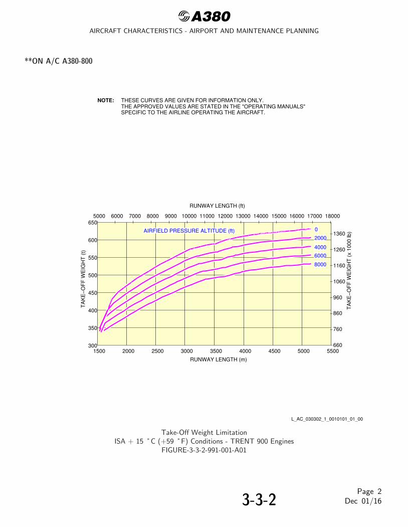
@A380AIRCRAFT CHARACTERISTICS - AIRPORT AND MAINTENANCE PLANNING
**ON A/C A380-800
NOTE: THESE CURVES ARE GIVEN FOR INFORMATION ONLY.THE APPROVED VALUES ARE STATED IN THE "OPERATING MANUALS"SPECIFIC TO THE AIRLINE OPERATING THE AIRCRAFT.
RUNWAY LENGTH (ft)
RUNWAY LENGTH (m)
TA
KE
−O
FF
WE
IGH
T (
t)
300
350
400
450
500
550
600
650
1500 2000 2500 3000 3500 4000 4500 5000 5500660
760
860
960
1060
1160
1260
1360
5000 6000 7000 8000 9000 10000 11000 12000 13000 14000 15000 16000 17000 18000
0
2000
6000
4000
8000
TA
KE
−O
FF
WE
IGH
T (
x 10
00 lb
)AIRFIELD PRESSURE ALTITUDE (ft)
L_AC_030302_1_0010101_01_00
Take-Off Weight LimitationISA + 15 ˚C (+59 ˚F) Conditions - TRENT 900 Engines
FIGURE-3-3-2-991-001-A01
3-3-2Page 2
Dec 01/16

@A380AIRCRAFT CHARACTERISTICS - AIRPORT AND MAINTENANCE PLANNING
**ON A/C A380-800
NOTE: THESE CURVES ARE GIVEN FOR INFORMATION ONLY.THE APPROVED VALUES ARE STATED IN THE "OPERATING MANUALS"SPECIFIC TO THE AIRLINE OPERATING THE AIRCRAFT.
RUNWAY LENGTH (ft)
RUNWAY LENGTH (m)
TA
KE
−O
FF
WE
IGH
T (
t)
350
400
450
500
550
600
650
1500 2000 2500 3000 3500 4000 4500 5000 5500660
760
860
960
1060
1160
1260
1360
5000 6000 7000 8000 9000 10000 11000 12000 13000 14000 15000 16000 17000 18000
0
2000
6000
4000
8000
TA
KE
−O
FF
WE
IGH
T (
x 10
00 lb
)300
AIRFIELD PRESSURE ALTITUDE (ft)
L_AC_030302_1_0080101_01_00
Take-Off Weight LimitationISA + 15 ˚C (+59 ˚F) Conditions - GP 7200 Engines
FIGURE-3-3-2-991-008-A01
3-3-2Page 3
Dec 01/16
@A380AIRCRAFT CHARACTERISTICS - AIRPORT AND MAINTENANCE PLANNING
3-4-1 Landing Field Length - ISA Conditions
**ON A/C A380-800
Landing Field Length
1. This section provides the landing field length on a dry runway.
3-4-1Page 1
Dec 01/16

@A380AIRCRAFT CHARACTERISTICS - AIRPORT AND MAINTENANCE PLANNING
**ON A/C A380-800
NOTE: THESE CURVES ARE GIVEN FOR INFORMATION ONLY.THE APPROVED VALUES ARE STATED IN THE "OPERATING MANUALS"SPECIFIC TO THE AIRLINE OPERATING THE AIRCRAFT.
1400
1500
1600
1700
1800
1900
2000
2100
2200
2300
2400
2500
2600
2700
2800
280 300 320 340 360 380 400 420 440 4604600
5000
5400
5800
6200
6600
7000
7400
7800
8200
8600
9000
620 670 720 770 820 870 920 970
GROSS WEIGHT (t)
VALID FOR ALL TEMPERATURES
AIRFIELD ELEVATION (ft)
0
2000
6000
4000
8000
LAN
DIN
G F
IELD
LE
NG
TH
(ft)
LAN
DIN
G F
IELD
LE
NG
TH
(m
)
GROSS WEIGHT (x 1000 lb)
L_AC_030401_1_0010101_01_01
Landing Field LengthDry Runway
FIGURE-3-4-1-991-001-A01
3-4-1Page 2
Dec 01/16

@A380AIRCRAFT CHARACTERISTICS - AIRPORT AND MAINTENANCE PLANNING
3-5-0 Final Approach Speed
**ON A/C A380-800
Final Approach Speed
1. This section gives the final approach speed which is the indicated airspeed at threshold in the landingconfiguration at the certificated maximum flap setting and maximum landing weight at standardatmospheric conditions. The approach speed is used to classify the aircraft into Aircraft ApproachCategory, a grouping of aircraft based on the indicated airspeed at threshold.
2. The final approach speed is 138 kt at a Maximum Landing Weight (MLW) of 395 000 kg (870 826lb) and classifies the aircraft into the Aircraft Approach Category C.
NOTE : This value is given for information only.
3-5-0Page 1
Dec 01/16

@A380AIRCRAFT CHARACTERISTICS - AIRPORT AND MAINTENANCE PLANNING
GROUND MANEUVERING
4-1-0 General Information
**ON A/C A380-800
General
1. This section provides aircraft turning capability and maneuvering characteristics.
For ease of presentation, this data has been determined from the theoretical limits imposed by thegeometry of the aircraft, and where noted, provides for a normal allowance for tire slippage. As such,it reflects the turning capability of the aircraft in favorable operating circumstances. This data shouldonly be used as a guidelines for the method of determination of such parameters and for themaneuvering characteristics of this aircraft type.
In ground operating mode, varying airline practices may demand that more conservative turningprocedures be adopted to avoid excessive tire wear and reduce possible maintenance problems. Airlineoperating techniques will vary in the level of performance, over a wide range of operatingcircumstances throughout the world. Variations from standard aircraft operating patterns may benecessary to satisfy physical constraints within the maneuvering area, such as adverse grades, limitedarea or a high risk of jet blast damage. For these reasons, ground maneuvering requirements shouldbe coordinated with the airlines in question prior to layout planning.
4-1-0Page 1
Dec 01/16

@A380AIRCRAFT CHARACTERISTICS - AIRPORT AND MAINTENANCE PLANNING
4-2-0 Turning Radii
**ON A/C A380-800
Turning Radii
1. This section provides the turning radii.
4-2-0Page 1
Dec 01/16

@A380AIRCRAFT CHARACTERISTICS - AIRPORT AND MAINTENANCE PLANNING
**ON A/C A380-800
NOTE:
R4
R3
R6
FOR TURNING RADII VALUES, REFER TO SHEET 2.
55°
60°
65°
29.83 m
70°
R5
(97.9 ft)
L_AC_040200_1_0010101_01_01
Turning Radii(Sheet 1)
FIGURE-4-2-0-991-001-A01
4-2-0Page 2
Dec 01/16

@A380AIRCRAFT CHARACTERISTICS - AIRPORT AND MAINTENANCE PLANNING
**ON A/C A380-800
2100.16328.6
TYPEOF
TURN
20°
STEERINGANGLE
17.9°
EFFECTIVESTEERING
ANGLE
mft
135.45444.4
101.01331.4
115.87380.1
278.86258.7
25° 22.7°mft
113.14371.2
80.12262.9
94.90311.4
265.69215.5
30° 27.5°mft
98.90324.5
67.33220.9
81.91268.7
256.84186.5
35° 32.1°mft
88.97291.9
58.83193.0
73.13239.9
250.59166.0
40° 36.6°mft
81.61267.8
52.89173.5
66.84219.3
246.02151.0
45° 41.0°mft
75.94249.1
48.61159.5
62.16203.9
242.61139.8
50° 45.1°mft
71.43234.4
45.45149.1
58.57192.2
140.13131.6
55° 51.2°mft
67.02219.9
43.22141.8
55.43181.9
137.64123.5
60° 57.3°mft
62.60205.4
40.98134.5
52.29171.5
135.15115.3
65° 63.4°mft
58.18190.9
38.75127.1
49.15161.2
132.66107.2
70° 69.5°mft
53.76176.4
36.52119.8
46.01150.9
R3 R4 R5 R6NLG WING NOSE THS
A380−800 TURNING RADII
NOTE:TYPE 1 TURNS USE :ASYMMETRIC THRUST − BOTH ENGINES ON THE INSIDE OF THE TURN TO BE AT IDLE THRUST.DIFFERENTIAL BRAKING − BRAKING APPLIED TO THE WING GEAR WHEELS ON THE INSIDE OF
TYPE 2 TURNS USE :SYMMETRIC THRUST AND NO BRAKING.
THE TURN.
L_AC_040200_1_0020101_01_01
Turning Radii(Sheet 2)
FIGURE-4-2-0-991-002-A01
4-2-0Page 3
Dec 01/16

@A380AIRCRAFT CHARACTERISTICS - AIRPORT AND MAINTENANCE PLANNING
4-3-0 Minimum Turning Radii
**ON A/C A380-800
Minimum Turning Radii
1. This section provides the minimum turning radii.
4-3-0Page 1
Dec 01/16

@A380AIRCRAFT CHARACTERISTICS - AIRPORT AND MAINTENANCE PLANNING
**ON A/C A380-800
(MINIMUMTURNING WIDTH)
A
R4
R3
R5Y
R6
55°
60°
65°
70°
TURN PERFORMED WITH ASYMMETRIC THRUST AND DIFFERENTIAL BRAKING.
NOTE:
EFFECTIVESTEERING
ANGLE
STEERINGANGLE
TYPEOF
TURNY
m
ft70° 69.5°
A380−800 MINIMUM TURNING RADIUS
11.08
36.3
A
50.91
167.0
R3 R4 R5 R6NLG WING NOSE THS
32.66
107.2
53.76
176.4
36.52
119.8
46.01
150.91
29.83 m (97.9 ft)
OUTSIDE FACEOF TIRE
L_AC_040300_1_0010101_01_02
Minimum Turning RadiiFIGURE-4-3-0-991-001-A01
4-3-0Page 2
Dec 01/16

@A380AIRCRAFT CHARACTERISTICS - AIRPORT AND MAINTENANCE PLANNING
4-4-0 Visibility from Cockpit in Static Position
**ON A/C A380-800
Visibility from Cockpit in Static Position
1. This section gives the visibility from cockpit in static position.
4-4-0Page 1
Dec 01/16

@A380AIRCRAFT CHARACTERISTICS - AIRPORT AND MAINTENANCE PLANNING
**ON A/C A380-800
PERPENDICULAR TOLONGITUDINAL AXIS.
VISUAL ANGLES IN VERTICALPLANE THROUGH PILOTEYE POSITION.
DIMENSIONS ARE APPROXIMATE
107°
CAPTAIN FIELD OF VIEW
121°
107°
MAX AFT VISION WITH HEAD TURNEDAROUND SPINAL COLUMN.WING TIP CAN BE SEEN WHEN HEAD IS MOVEDTO THE SIDE.
VISUAL ANGLES IN HORIZONTALPLANE THROUGH PILOTEYE POSITION.
FIRST OFFICERFIELD OF VIEW
30°
24°
VISUAL ANGLES IN PLANE
30°
121°
NOT TO BE USED FORLANDING APPROACH VISIBILITY
NOTE:PILOT EYE POSITION WHEN PILOT’S EYES ARE IN LINE WITH THE RED AND WHITE BALLS.
ZONE THAT CANNOT BE SEEN
17.36 m(56.96 ft)
4.97 m(16.31 ft)
2.92 m(9.58 ft)7.17 m
(23.52 ft)
31°
19.5°
24°
L_AC_040400_1_0010101_01_01
Visibility from Cockpit in Static PositionFIGURE-4-4-0-991-001-A01
4-4-0Page 2
Dec 01/16

@A380AIRCRAFT CHARACTERISTICS - AIRPORT AND MAINTENANCE PLANNING
**ON A/C A380-800
CA
PT
AIN
FIE
LD O
F V
IEW
SH
OW
N.
FIR
ST
OF
FIC
ER
FIE
LD O
F V
IEW
SY
MM
ET
RIC
AL.
EX
AM
PLE
: WH
EN
CA
PT
AIN
TU
RN
S H
IS H
EA
D B
Y 9
0° L
EF
T, V
ISIB
ILIT
YW
ILL
BE
30°
UP
AN
D 2
4° D
OW
N T
HR
OU
GH
TH
E S
LID
ING
WIN
DO
W F
RA
ME
.
CA
PT
AIN
FIX
ED
WIN
DO
W
130°
120°
110°
100°
90°
80°
70°
60°
50°
40°
30°
20°
10°
0°10
°20
°30
°40
°50
°60
°70
°80
°90
°100
°110
°120
°130
°140
°
30°
20°
10°
0°10°
20°
30°
40°
50°
CA
PT
AIN
SLI
DIN
GW
IND
OW
CA
PT
AIN
WIN
DS
HIE
LD
FIR
ST
OF
FIC
ER
WIN
DS
HIE
LDF
IRS
T O
FF
ICE
RF
IXE
D W
IND
OW
FIR
ST
OF
FIC
ER
SLI
DIN
G W
IND
OW
PIL
OT
EY
E P
OS
ITIO
N(C
AP
TA
IN P
OS
ITIO
N)
A38
0
AR
P 4
101−
2
24°
150°
L_AC_040400_1_0020101_01_00
Binocular Visibility Through Windows from Captain Eye PositionFIGURE-4-4-0-991-002-A01
4-4-0Page 3
Dec 01/16

@A380AIRCRAFT CHARACTERISTICS - AIRPORT AND MAINTENANCE PLANNING
4-5-0 Runway and Taxiway Turn Paths
**ON A/C A380-800
Runway and Taxiway Turn Paths
1. Runway and Taxiway Turn Paths
4-5-0Page 1
Dec 01/16

@A380AIRCRAFT CHARACTERISTICS - AIRPORT AND MAINTENANCE PLANNING
4-5-1 135˚ Turn - Runway to Taxiway
**ON A/C A380-800
135˚ Turn - Runway to Taxiway
1. This section gives the 135˚ turn -- runway to taxiway.
4-5-1Page 1
Dec 01/16

@A380AIRCRAFT CHARACTERISTICS - AIRPORT AND MAINTENANCE PLANNING
**ON A/C A380-800
APPROX 6.6 m(22 ft)
FILLET R = 25.5 m(85 ft)
TURN R = 45 m(150 ft)
APPROX 4.9 m(16 ft)
OFFSET 7 m(23 ft)
NOMINAL
45 m(150 ft)
23 m(75 ft)
RUNWAYCENTERLINE TAXIWAY CENTERLINE
FAA LEAD−IN FILLET
L = 75 m (250 ft)
NOTE: FAA GROUP V FACILITIES.
NLG PATH
WLG PATH
COCKPIT PATH
L_AC_040501_1_0010101_01_01
135˚ Turn -- Runway to TaxiwayJudgemental Oversteer Method
FIGURE-4-5-1-991-001-A01
4-5-1Page 2
Dec 01/16

@A380AIRCRAFT CHARACTERISTICS - AIRPORT AND MAINTENANCE PLANNING
**ON A/C A380-800
NLG PATH
WLG PATH
NOTE: FAA GROUP VI FACILITIES.
FILLET R = 25.5 m(85 ft)
APPROX 5.8 m(19 ft)
TURN R = 51 m(167 ft)
60 m(200 ft)
30 m(100 ft)
RUNWAY CENTERLINE
TAXIWAY CENTERLINE
FAA LEAD−IN FILLET
L = 75 m (250 ft)
L_AC_040501_1_0020101_01_01
135˚ Turn -- Runway to TaxiwayCockpit Tracks Centreline Method
FIGURE-4-5-1-991-002-A01
4-5-1Page 3
Dec 01/16

@A380AIRCRAFT CHARACTERISTICS - AIRPORT AND MAINTENANCE PLANNING
4-5-2 90˚ Turn - Runway to Taxiway
**ON A/C A380-800
90˚ Turn - Runway to Taxiway
1. This section gives the 90˚ turn -- runway to taxiway.
4-5-2Page 1
Dec 01/16
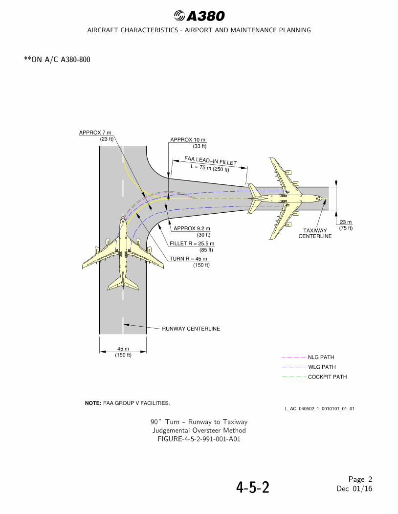
@A380AIRCRAFT CHARACTERISTICS - AIRPORT AND MAINTENANCE PLANNING
**ON A/C A380-800
23 m(75 ft)
45 m(150 ft)
RUNWAY CENTERLINE
APPROX 9.2 m(30 ft)
FILLET R = 25.5 m(85 ft)
TURN R = 45 m(150 ft)
APPROX 10 m(33 ft)
APPROX 7 m(23 ft)
TAXIWAYCENTERLINE
FAA LEAD−IN FILLETL = 75 m (250 ft)
NOTE: FAA GROUP V FACILITIES.
NLG PATH
WLG PATH
COCKPIT PATH
L_AC_040502_1_0010101_01_01
90˚ Turn -- Runway to TaxiwayJudgemental Oversteer Method
FIGURE-4-5-2-991-001-A01
4-5-2Page 2
Dec 01/16
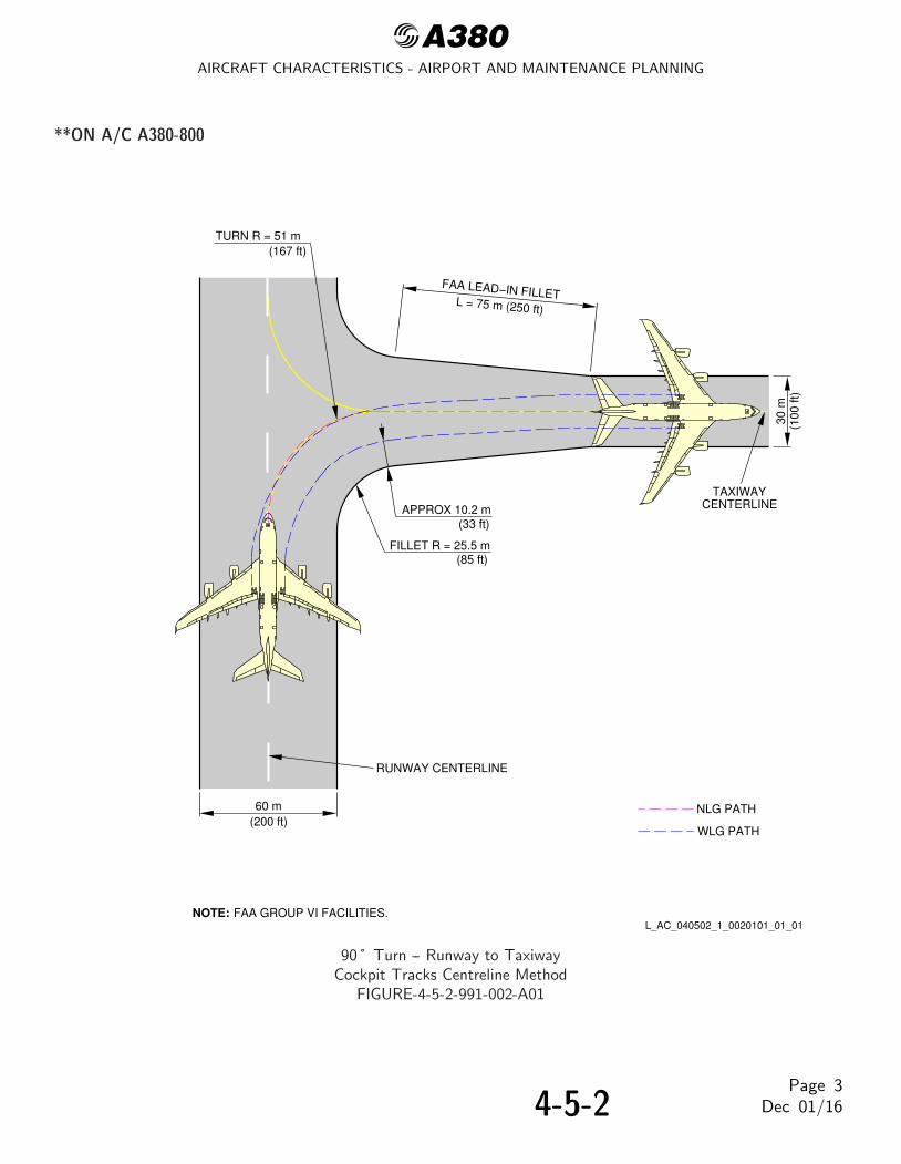
@A380AIRCRAFT CHARACTERISTICS - AIRPORT AND MAINTENANCE PLANNING
**ON A/C A380-800
TURN R = 51 m(167 ft)
30 m
(100
ft)
60 m(200 ft)
RUNWAY CENTERLINE
FILLET R = 25.5 m(85 ft)
APPROX 10.2 m(33 ft)
TAXIWAYCENTERLINE
FAA LEAD−IN FILLETL = 75 m (250 ft)
NOTE: FAA GROUP VI FACILITIES.
NLG PATH
WLG PATH
L_AC_040502_1_0020101_01_01
90˚ Turn -- Runway to TaxiwayCockpit Tracks Centreline Method
FIGURE-4-5-2-991-002-A01
4-5-2Page 3
Dec 01/16

@A380AIRCRAFT CHARACTERISTICS - AIRPORT AND MAINTENANCE PLANNING
4-5-3 180˚ Turn on a Runway
**ON A/C A380-800
180˚ Turn on a Runway
1. This section gives the 180˚ turn on a runway.
4-5-3Page 1
Dec 01/16

@A380AIRCRAFT CHARACTERISTICS - AIRPORT AND MAINTENANCE PLANNING
**ON A/C A380-800
NOTE:
4.5 m(15 ft)
4.5 m(15 ft)
0.7 m(2 ft)
16.8 m(55 ft)
31.2 m(102 ft)
23.2 m(76 ft)
R4 = 54 m(177 ft)
R5 = 36.6 m(120 ft)
R6 = 46 m(151 ft)
51 m(167 ft)
60 m(200 ft)
RUNWAYCENTERLINE
NLG PATH
WLG PATH
NOSE TIP PATH
WING TIP PATH
TAIL TIP PATH
R3 = 32.7 m(107 ft)
NLG WHEELOUTER−FACE PATH70° NOSE GEAR STEERING − ASYMMETRIC THRUST AND BRAKING
ON A 60 m (200 ft) WIDE RUNWAY.L_AC_040503_1_0010101_01_01
180˚ Turn on a RunwayFIGURE-4-5-3-991-001-A01
4-5-3Page 2
Dec 01/16

@A380AIRCRAFT CHARACTERISTICS - AIRPORT AND MAINTENANCE PLANNING
4-5-4 90˚ Turn - Taxiway to Taxiway
**ON A/C A380-800
90˚ Turn - Taxiway to Taxiway
1. This section gives the 90˚ turn - taxiway to taxiway.
4-5-4Page 1
Dec 01/16

@A380AIRCRAFT CHARACTERISTICS - AIRPORT AND MAINTENANCE PLANNING
**ON A/C A380-800
TAXIWAY CENTERLINE
23 m(75 ft)
23 m(75 ft)
NOMINAL OFFSET 7 m(23 ft)
APPROX 8.9 m(29 ft)
FILLET R = 25.5 m(85 ft)
TURN R = 45 m(150 ft)
APPROX 10 m(33 ft)
FAA LEAD−IN FILLETL = 75 m (250 ft)
TAXIWAYCENTERLINE
NOTE: FAA GROUP V FACILITIES.
NLG PATH
WLG PATH
COCKPIT PATH
L_AC_040504_1_0010101_01_01
90˚ Turn -- Taxiway to TaxiwayJudgemental Oversteer Method
FIGURE-4-5-4-991-001-A01
4-5-4Page 2
Dec 01/16

@A380AIRCRAFT CHARACTERISTICS - AIRPORT AND MAINTENANCE PLANNING
**ON A/C A380-800
APPROX 8.7 m(29 ft)
TAXIWAY CENTERLINE
30 m
(100
ft)
FILLET R = 25.5 m(85 ft)
TURN R = 51 m(167 ft)
TAXIWAYCENTERLINE
FAA LEAD−IN FILLETL = 75 m (250 ft)
30 m(100 ft) NLG PATH
WLG PATH
NOTE: FAA GROUP VI FACILITIES.L_AC_040504_1_0020101_01_01
90˚ Turn -- Taxiway to TaxiwayCockpit Tracks Centreline Method
FIGURE-4-5-4-991-002-A01
4-5-4Page 3
Dec 01/16

@A380AIRCRAFT CHARACTERISTICS - AIRPORT AND MAINTENANCE PLANNING
4-5-5 135˚ Turn - Taxiway to Taxiway
**ON A/C A380-800
135˚ Turn - Taxiway to Taxiway
1. This section gives the 135˚ turn - taxiway to taxiway.
4-5-5Page 1
Dec 01/16

@A380AIRCRAFT CHARACTERISTICS - AIRPORT AND MAINTENANCE PLANNING
**ON A/C A380-800
23 m(75 ft)
TAXIWAY CENTERLINE
FILLET R = 25.5 m(85 ft)
APPROX 8.5 m(28 ft)
TAXIWAY CENTERLINE
23 m(75 ft)
TURN R = 45 m(150 ft)
APPROX 7 m(23 ft)
APPROX 4.9 m(16 ft)
FAA LEAD−IN FILLET
L = 75 m (250 ft)
NLG PATH
WLG PATH
COCKPIT PATH
NOTE: FAA GROUP V FACILITIES.L_AC_040505_1_0010101_01_01
135˚ Turn -- Taxiway to TaxiwayJudgemental Oversteer Method
FIGURE-4-5-5-991-001-A01
4-5-5Page 2
Dec 01/16

@A380AIRCRAFT CHARACTERISTICS - AIRPORT AND MAINTENANCE PLANNING
**ON A/C A380-800
FILLET R = 25.5 m(85 ft)
APPROX 7.4 m(24 ft)
30 m(100 ft)
TURN R = 51 m(167 ft)
TAXIWAY CENTERLINE
TAXIWAY CENTERLINE
FAA LEAD−IN FILLET
L = 75 m (250 ft)
NLG PATH
WLG PATH
30 m(100 ft)
NOTE: FAA GROUP VI FACILITIES.L_AC_040505_1_0020101_01_01
135˚ Turn -- Taxiway to TaxiwayCockpit Tracks Centerline Method
FIGURE-4-5-5-991-002-A01
4-5-5Page 3
Dec 01/16

@A380AIRCRAFT CHARACTERISTICS - AIRPORT AND MAINTENANCE PLANNING
4-6-0 Runway Holding Bay (Apron)
**ON A/C A380-800
Runway Holding Bay (Apron)
1. This section gives the runway holding bay (Apron).
4-6-0Page 1
Dec 01/16

@A380AIRCRAFT CHARACTERISTICS - AIRPORT AND MAINTENANCE PLANNING
**ON A/C A380-800
6.1 m(20 ft)
RUNWAY CENTERLINETAXIWAY
CENTERLINE
6.1 m(20 ft)
190 m(625 ft)
30 m(100 ft)
60 m(200 ft)
HOLDING POINT
12.2 m(40 ft)
90 m(300 ft)110 m
(360 ft)
NOTE: COORDINATE WITH USING AIRLINE FOR SPECIFIC PLANNED OPERATING PROCEDURE.
L_AC_040600_1_0010101_01_01
Runway Holding Bay (Apron)FIGURE-4-6-0-991-001-A01
4-6-0Page 2
Dec 01/16

@A380AIRCRAFT CHARACTERISTICS - AIRPORT AND MAINTENANCE PLANNING
4-7-0 Minimum Line-Up Distance Corrections
**ON A/C A380-800
Minimum Line-Up Distance Corrections
1. The ground manoeuvres were performed using asymmetric thrust and differential only braking toinitiate the turn.TODA: Take-Off Available DistanceASDA: Acceleration-Stop Distance Available
2. 90˚ Turn on Runway EntryThis section gives the minimum line-up distance correction for a 90˚ turn on runway entry.This manoeuvre consists in a 90˚ turn at minimum turn radius starting with the edge of the WLG ata distance of 4.5 m (15 ft) from taxiway edge, and finishing with the aircraft aligned on thecenterline of the runway, see FIGURE 4-7-0-991-003-A.During the turn, all the clearances must meet the minimum value of 4.5 m (15 ft) for this category ofaircraft as recommended in ICAO Annex 14.
3. 180˚ Turn on Runway Turn PadThis section gives the minimum line-up distance correction for a 180˚ turn on runway turn pad.This manoeuvre consists in a 180˚ turn at minimum turn radius on a standard ICAO runway turnpad geometry, .It starts with the edge of the WLG at 4.5 m (15 ft) from pavement edge, and it finishes with theaircraft aligned on the centerline of the runway, see FIGURE 4-7-0-991-004-A.During the turn, all the clearances must meet the minimum value of 4.5 m (15 ft) for this category ofaircraft as recommended in ICAO Annex 14.
4. 180˚ Turn on Runway WidthThis section gives the minimum line-up distance correction for a 180˚ turn on runway width.For this manoeuvre, the pavement width is considered to be the runway width, which is a frozenparameter (45 m (150 ft) and 60 m (200 ft)).As per the ”180˚ turn on runway” standard operating procedures described in the Flight CrewOperating Manual, the aircraft is initially angled with respect to runway centerline when starting the180˚ turn, see FIGURE 4-7-0-991-005-A.During the turn, all the clearances must meet the minimum value of 4.5 m (15 ft) for this category ofaircraft as recommended in ICAO Annex 14.
4-7-0Page 1
Dec 01/16

@A380AIRCRAFT CHARACTERISTICS - AIRPORT AND MAINTENANCE PLANNING
**ON A/C A380-800
> 4.5 m(15 ft)
90° TURN ON RUNWAY ENTRY
AIRCRAFTTYPE
MAXSTEERING
ANGLE
(STANDARD WIDTH)
MINIMUM LINE−UPDISTANCE CORRECTION
ON TODA ON ASDA ON TODA ON ASDA
MINIMUM LINE−UPDISTANCE CORRECTION
70°A380−800 94 ft28.6 m 192 ft58.5 m 75 ft22.8 m 173 ft52.7 m
TAXIWAYCENTERLINE
ASDA
4.5 m(15 ft)
TODA
RUNWAY CENTERLINE
45 m (150 ft) WIDE RUNWAY60 m (200 ft) WIDE RUNWAY
NOTE:
ASDA: ACCELERATION−STOP DISTANCE AVAILABLETODA: TAKE−OFF DISTANCE AVAILABLE
L_AC_040700_1_0030101_01_00
Minimum Line-Up Distance Corrections90˚ Turn on Runway EntryFIGURE-4-7-0-991-003-A01
4-7-0Page 2
Dec 01/16

@A380AIRCRAFT CHARACTERISTICS - AIRPORT AND MAINTENANCE PLANNING
**ON A/C A380-800
180° TURN ON RUNWAY TURNPAD
AIRCRAFTTYPE
STEERINGANGLE
MAX(STANDARD WIDTH)
DISTANCECORRECTION
MINIMUM LINE−UP
70°A380−800224 ft68.1 m
TODA
ASDA
MINIMUM PAVEMENT WIDTH
ON TODA130 ft39.5 m
ON ASDA227 ft69.3 m
PAVEMENTWIDTH
MINIMUMREQUIRED
DISTANCECORRECTION
MINIMUM LINE−UP
209.9 ft64 mON TODA
122 ft37.1 mON ASDA
219 ft66.9 m
PAVEMENTWIDTH
MINIMUMREQUIRED
RUNWAY CENTERLINE
NOTE:
ASDA: ACCELERATION−STOP DISTANCE AVAILABLETODA: TAKE−OFF DISTANCE AVAILABLE
45 m (150 ft) WIDE RUNWAY 60 m (200 ft) WIDE RUNWAY
4.5 m(15 ft)
4.5 m(15 ft)> 4.5 m
(15 ft)
L_AC_040700_1_0040101_01_00
Minimum Line-Up Distance Corrections180˚ Turn on Runway Turn Pad
FIGURE-4-7-0-991-004-A01
4-7-0Page 3
Dec 01/16

@A380AIRCRAFT CHARACTERISTICS - AIRPORT AND MAINTENANCE PLANNING
**ON A/C A380-800
180° TURN ON RUNWAY WIDTH
AIRCRAFTTYPE
MAXSTEERING
ANGLE
(STANDARD WIDTH)
MINIMUM LINE−UPDISTANCE CORRECTION
ON TODA ON ASDA ON TODA ON ASDA
MINIMUM LINE−UPDISTANCE CORRECTION
70°A380−800 NOT POSSIBLE NOT POSSIBLE
ASDA
>4.5 m(15 ft)
4.5 m(15 ft)
TODA
NOTE:
IN THE A380 FCOM, THERE IS AN OPERATIONAL PROCEDURE THAT DESCRIBES HOW TO PERFORM A 180°TURN ON A 60 m (200 ft) RUNWAY WIDTH, BUT THE RECOMMENDED 4.5 m (15 ft) MARGINS CANNOT BE MET.
4.5 m(15 ft)
RUNWAY CENTERLINE
45 m (150 ft) WIDE RUNWAY60 m (200 ft) WIDE RUNWAY
ASDA: ACCELERATION−STOP DISTANCE AVAILABLETODA: TAKE−OFF DISTANCE AVAILABLE
15°
L_AC_040700_1_0050101_01_00
Minimum Line-Up Distance Corrections180˚ Turn on Runway WidthFIGURE-4-7-0-991-005-A01
4-7-0Page 4
Dec 01/16

@A380AIRCRAFT CHARACTERISTICS - AIRPORT AND MAINTENANCE PLANNING
4-8-0 Aircraft Mooring
**ON A/C A380-800
Aircraft Mooring
1. This section provides information on aircraft mooring.
4-8-0Page 1
Dec 01/16

@A380AIRCRAFT CHARACTERISTICS - AIRPORT AND MAINTENANCE PLANNING
**ON A/C A380-800
A
FWD
SLING
TOWING FITTING
MOVABLE PIN
LOCKING SCREW
HOOK
HOOK PIN
MOORING POINT
A
L_AC_040800_1_0010101_01_00
Aircraft MooringFIGURE-4-8-0-991-001-A01
4-8-0Page 2
Dec 01/16

@A380AIRCRAFT CHARACTERISTICS - AIRPORT AND MAINTENANCE PLANNING
TERMINAL SERVICING
5-1-0 Aircraft Servicing Arrangements
**ON A/C A380-800
Aircraft Servicing Arrangements
1. This section provides typical ramp layouts, showing the various GSE items in position during typicalturn-round scenarios.
These ramp layouts show typical arrangements only. Each operator will have its own specificrequirements/regulations for positioning and operation on the ramp.
This table gives the symbols used on servicing diagrams.
GROUND SUPPORT EQUIPMENT
AC AIR CONDITIONING UNITAS AIR START UNITBULK BULK TRAINCAT CATERING TRUCKCB CONVEYOR BELTCLEAN CLEANING TRUCKFUEL FUEL HYDRANT DISPENSER or TANKERGPU GROUND POWER UNITLDCL LOWER DECK CARGO LOADERLV LAVATORY VEHICLEPBB PASSENGER BOARDING BRIDGEPS PASSENGER STAIRSTOW TOW TRACTORUDCAT UPPER DECK CATERING TRUCKULD ULD TRAINWV POTABLE WATER VEHICLE
5-1-0Page 1
Dec 01/16
@A380AIRCRAFT CHARACTERISTICS - AIRPORT AND MAINTENANCE PLANNING
5-1-1 Typical Ramp Layout (Open Apron)
**ON A/C A380-800
Typical Ramp Layout (Open Apron)
1. This section provides the typical ramp layout (Open Apron).The Stand Safety Line delimits the Aircraft Safety Area (minimum distance of 7.5 m (24.61 ft) fromthe aircraft). No vehicle must be parked in this area before complete stop of the aircraft (wheelchocks in position on landing gears) and the beacon lights are off.
5-1-1Page 1
Dec 01/16

@A380AIRCRAFT CHARACTERISTICS - AIRPORT AND MAINTENANCE PLANNING
**ON A/C A380-800
CAT
LD CL
GPU
GPU
ULD
BULK
TOW
METERS
FEET16 320
0 5 10 15
48
LD CL
CLEAN
STAND SAFETY LINE
CB
FUEL
AS
CAT
AC
PS
PS
PS
CATLV
UDCAT
WV
ULD
L_AC_050101_1_0010101_01_02
Typical Ramp LayoutOpen Apron
FIGURE-5-1-1-991-001-A01
5-1-1Page 2
Dec 01/16

@A380AIRCRAFT CHARACTERISTICS - AIRPORT AND MAINTENANCE PLANNING
5-1-2 Typical Ramp Layout (Gate)
**ON A/C A380-800
Typical Ramp Layout (Gate)
1. This section provides the baseline ramp layout (Gate).The Stand Safety Line delimits the Aircraft Safety Area (minimum distance of 7.5 m (24.61 ft) fromthe aircraft). No vehicle must be parked in this area before complete stop of the aircraft (wheelchocks in position on landing gears) and the beacon lights are off.
5-1-2Page 1
Dec 01/16

@A380AIRCRAFT CHARACTERISTICS - AIRPORT AND MAINTENANCE PLANNING
**ON A/C A380-800
GPU
GPU
LD CL
ULD
BULK
LD CL
CLEAN
CB
AS
CAT
CAT
AC
FUELFUEL
PBB
PBB
CAT LV
UDCAT
WV
ULD
STAND SAFETY LINE
METERS
FEET16 320
0 5 10 15
48 TOW
L_AC_050102_1_0010101_01_02
Typical Ramp LayoutGate
FIGURE-5-1-2-991-001-A01
5-1-2Page 2
Dec 01/16

@A380AIRCRAFT CHARACTERISTICS - AIRPORT AND MAINTENANCE PLANNING
5-2-1 Typical Turn-Round Time - Standard Servicing Via Main Deck and Upper Deck
**ON A/C A380-800
Typical Turn-Round Time - Standard Servicing Via Main Deck and Upper Deck
1. This section provides a typical turn-round time chart showing the typical time for ramp activitiesduring aircraft turn-round.Actual times may vary due to each operator’s specific practices, resources, equipment and operatingconditions.
2. Assumptions used for standard servicing via main and upper deck during typical turn-round time
A. PASSENGER HANDLING555 pax (22 F/C + 96 B/C + 437 Y/C).All passengers deplane and board the aircraft.2 Passenger Boarding Bridges (PBB) used at doors M2L and U1L.Equipment positioning main deck + opening door = +3 min.Closing door + equipment removal main deck = +3 min.Equipment positioning upper deck + opening door = +4 min.Closing door + equipment removal upper deck = +4 min.No Passenger with Reduced Mobility (PRM) on board.
Deplaning:- 356 pax at door M2L (22 F/C + 334 Y/C)- 199 pax at door U1L (96 B/C + 103 Y/C)- Deplaning rate = 25 pax/min per door- Priority deplaning for premium passengers.
Boarding:- 356 pax at door M2L (22 F/C + 334 Y/C)- 199 pax at door U1L (96 B/C + 103 Y/C)- Boarding rate = 15 pax/min per door- Last Pax Seating allowance (LPS) + headcounting = +4 min.
B. CARGO2 cargo loaders + 1 belt loader.Opening door + equipment positioning = +2.5 min.Equipment removal + closing door = +2.5 min.
100% cargo exchange:- FWD cargo compartment: 20 containers- AFT cargo compartment: 16 containers- Bulk cargo compartment: 1 000 kg (2 205 lb).
Container unloading/loading times:
5-2-1Page 1
Dec 01/16

@A380AIRCRAFT CHARACTERISTICS - AIRPORT AND MAINTENANCE PLANNING
- Unloading = 1.2 min/container- Loading = 1.4 min/container.
Bulk unloading/loading times:- Unloading = 110 kg/min (243 lb/min)- Loading = 95 kg/min (209 lb/min).
C. REFUELING242 700 l (64 115 US gal) at 40 psig.Dispenser positioning + connection = +8 min.Disconnection + dispenser removal = +8 min.
D. CLEANINGCleaning is performed in available time.
E. CATERING3 main deck catering trucks + 1 upper deck catering truck.Main deck equipment positioning + door opening = +5 min.Main deck closing door + equipment removal = 3 min.Upper deck equipment positioning + door opening = +9 min.Upper deck closing door + equipment removal = 4 min.
Full Size Trolley Equivalent (FSTE) to unload and load: 78 FSTE- 28 FSTE at door M2R- 16 FSTE at door M4R- 23 FSTE at door U1R- 11 FSTE at door M5L.Time for trolley exchange = 1.5 min per FSTE.Time for trolley exchange via lift = 2 min per FSTE.
F. GROUND HANDLING/SERVICINGStart of operations:- Bridges/stairs: t0 = 0- Other equipment: t = t0 + 1 min.
Ground Power Unit (GPU): up to 4 x 90 kVA.Air conditioning: up to 4 hoses.Potable water servicing: 100% uplift, 1 700 l (449 US gal).Waste water servicing: draining + rinsing.
5-2-1Page 2
Dec 01/16

@A380AIRCRAFT CHARACTERISTICS - AIRPORT AND MAINTENANCE PLANNING
**ON A/C A380-800
GSE POSITIONING/REMOVAL
ACTIVITY
CRITICAL PATH
AT M2LDEPLANING/BOARDING
HEADCOUNTING & LPS
CATERING AT M4R
CLEANING AT M1R
CARGO FWD CC
BULK
REFUELING
POTABLE WATER SERVICING
WASTE WATER SERVICING
DEPLANING/BOARDINGAT U1L
CATERING AT U1R
CATERING AT M5L
CARGO AFT CC
CATERING AT M2R
100 20 30 40 50 60 70 80 90
TRT: 90 min
AVAILABLE TIME
L_AC_050201_1_0020101_01_03
Typical Turn-Round TimeServicing Via Main and Upper Deck
FIGURE-5-2-1-991-002-A01
5-2-1Page 3
Dec 01/16

@A380AIRCRAFT CHARACTERISTICS - AIRPORT AND MAINTENANCE PLANNING
5-2-2 Typical Turn-Round Time - Servicing Via Main Deck
**ON A/C A380-800
Typical Turn-Round Time - Servicing Via Main Deck
1. This section provides a typical turn-round time chart showing the typical time for ramp activitiesduring aircraft turn-round.Actual times may vary due to each operator’s specific practices, resources, equipment and operatingconditions.
2. Assumptions used for standard servicing via main deck only during typical turn-round time
A. PASSENGER HANDLING555 pax (22 F/C + 96 B/C + 437 Y/C).All passengers deplane and board the aircraft.2 Passenger Boarding Bridges (PBB) used at doors M1L and M2L.Equipment positioning main deck + opening door = +3 min.Closing door + equipment removal main deck = +3 min.No Passenger with Reduced Mobility (PRM) on board.
Deplaning:- 221 pax at door M1L (22 F/C + 96 B/C + 103 Y/C)- 334 pax at door M2L (334 Y/C)- Deplaning rate = 25 pax/min per door- Priority deplaning for premium passengers.
Boarding:- 221 pax at door M1L (22 F/C + 96 B/C + 103 Y/C)- 334 pax at door M2L (334 Y/C)- Boarding rate = 15 pax/min per door- Last Pax Seating allowance (LPS) + headcounting = +4 min.
B. CARGO2 cargo loaders + 1 belt loader.Opening door + equipment positioning = +2.5 min.Equipment removal + closing door = +2.5 min.
100% cargo exchange:- FWD cargo compartment: 20 containers- AFT cargo compartment: 16 containers- Bulk compartment: 1 000 kg (2 205 lb).
Container unloading/loading times:- Unloading = 1.2 min/container- Loading = 1.4 min/container.
5-2-2Page 1
Dec 01/16

@A380AIRCRAFT CHARACTERISTICS - AIRPORT AND MAINTENANCE PLANNING
Bulk unloading/loading times:- Unloading = 110 kg/min (243 lb/min)- Loading = 95 kg/min (209 lb/min).
C. REFUELING242 700 l (64 115 US gal) at 40 psig.Dispenser positioning + connection = +8 min.Disconnection + dispenser removal = +8 min.
D. CLEANINGCleaning is performed in available time.
E. CATERING3 main deck catering trucks.Main deck equipment positioning + door opening = +5 min.Main deck closing door + equipment removal = +3 min.Full Size Trolley Equivalent (FSTE) to unload and load: 78 FSTE.- 28 FSTE at door M2R- 16 FSTE at door M4R- 23 FSTE at door U1R- 11 FSTE at door M5L.Time for trolley exchange = 1.5 min per FSTE.Time for trolley exchange via lift = 2 min per FSTE.
F. GROUND HANDLING/SERVICINGStart of operations:- Bridges/stairs: t0 = 0- Other equipment: t = t0 + 1 min.
Ground Power Unit (GPU): up to 4 x 90 kVA.Air conditioning: up to 4 hoses.Potable water servicing: 100% uplift, 1 700 l (449 US gal).Waste water servicing: draining + rinsing.
5-2-2Page 2
Dec 01/16

@A380AIRCRAFT CHARACTERISTICS - AIRPORT AND MAINTENANCE PLANNING
**ON A/C A380-800
AT M1LDEPLANING/BOARDING
HEADCOUNTING & LPS
CATERING AT M4R
CLEANING AT M1R
CARGO FWD CC
BULK
REFUELING
POTABLE WATER SERVICING
WASTE WATER SERVICING
DEPLANING/BOARDINGAT M2L
CATERING AT M5L
CARGO AFT CC
CATERING AT M2R
20
GSE POSITIONING/REMOVAL
ACTIVITY
CRITICAL PATH
0 40 60 80 100 120 140
TRT: 140 min
AVAILABLE TIME
L_AC_050202_1_0010101_01_03
Typical Turn-Round TimeServicing Via Main Deck
FIGURE-5-2-2-991-001-A01
5-2-2Page 3
Dec 01/16

@A380AIRCRAFT CHARACTERISTICS - AIRPORT AND MAINTENANCE PLANNING
5-4-1 Ground Service Connections Layout
**ON A/C A380-800
Ground Service Connections Layout
1. This section gives the ground service connections layout.
5-4-1Page 1
Dec 01/16

@A380AIRCRAFT CHARACTERISTICS - AIRPORT AND MAINTENANCE PLANNING
**ON A/C A380-800
1 − GROUNDING POINT NLG2 − GROUND ELECTRICAL POWER CONNECTORS3 − POTABLE WATER DRAIN PANEL4 − OXYGEN SYSTEM
6 − HIGH PRESSURE AIR ENGINE START7 − VFG AND STARTER OIL FILLING8 − ENGINE OIL FILLING*9 − HYDRAULIC RESERVOIR SERVICING PANEL10 − YELLOW HYDRAULIC GROUND CONNECTOR
5 − LOW PRESSURE PRECONDITIONED AIR
13 − GROUNDING POINT WLG14 − GROUNDING POINT BLG
16 − OVERPRESSURE PROTECTOR17 − REFUEL/DEFUEL CONTROL PANEL18 − POTABLE WATER SERVICE PANEL
15 − NACA FLAME ARRESTOR
11 − GREEN HYDRAULIC GROUND CONNECTOR12 − PRESSURE REFUEL CONNECTORS
19 − TOILET AND WASTE SERVICE PANEL20 − APU OIL FILLING
1
34
15
12
1119
20
8 712
10
15
6
5
1718
2
13
14
9
8 7
8
7
87
16
16
15
16
NOTE:
*FOR THE GP 7200 ENGINE, THE ENGINE OIL SERVICING POINTS (8) ARE LOCATED SYMMETRICALLYON THE LH SIDE OF EACH ENGINE.
THE ENGINE OIL SERVICING POINTS (8) ARE SHOWN FOR THE RR TRENT 900 ENGINE.
L_AC_050401_1_0010101_01_03
Ground Service Connections LayoutFIGURE-5-4-1-991-001-A01
5-4-1Page 2
Dec 01/16

@A380AIRCRAFT CHARACTERISTICS - AIRPORT AND MAINTENANCE PLANNING
5-4-2 Grounding (Earthing) Points
**ON A/C A380-800
Grounding (Earthing) Points
1. Grounding (Earthing) Points
DISTANCEFROM AIRCRAFT CENTERLINEACCESS
AFT OF NOSELH SIDE RH SIDE
MEAN HEIGHTFROM GROUND
On Nose LandingGear leg
5.71 m(18.73 ft)
0.18 m(0.59 ft)
1.39 m(4.56 ft)
On Wing Gear leg(Inboard)
34.21 m(112.24 ft)
5.95 m(19.52 ft)
5.95 m(19.52 ft)
1.24 m(4.07 ft)
On Body Gear leg(Outboard)
37.16 m(121.92 ft)
2.85 m(9.35 ft)
2.85 m(9.35 ft)
1.38 m(4.53 ft)
On Body Gear leg(Inboard)
37.16 m(121.92 ft)
2.41 m(7.91 ft)
2.41 m(7.91 ft)
1.38 m(4.53 ft)
A. The grounding (earthing) stud on each landing gear is designed for use with a clip-on connector,such as an Appleton TGR.
B. The grounding (earthing) studs are used to connect the aircraft to approved ground (earth)connection on the ramp or in the hangar for:- Refuel/defuel operations- Maintenance operations- Bad weather conditions.
5-4-2Page 1
Dec 01/16

@A380AIRCRAFT CHARACTERISTICS - AIRPORT AND MAINTENANCE PLANNING
**ON A/C A380-800
GROUNDING (EARTHING)POINT
A
A
L_AC_050402_1_0010101_01_01
Grounding (Earthing) Point - NLGFIGURE-5-4-2-991-001-A01
5-4-2Page 2
Dec 01/16

@A380AIRCRAFT CHARACTERISTICS - AIRPORT AND MAINTENANCE PLANNING
**ON A/C A380-800
GROUNDING (EARTHING) POINT
A
A
L_AC_050402_1_0020101_01_01
Grounding (Earthing) Points - WLGFIGURE-5-4-2-991-002-A01
5-4-2Page 3
Dec 01/16

@A380AIRCRAFT CHARACTERISTICS - AIRPORT AND MAINTENANCE PLANNING
**ON A/C A380-800
GROUNDING (EARTHING) POINT
A
A
(RIGHT ONE SHOWN LEFT ONE SIMILAR)
L_AC_050402_1_0030101_01_01
Grounding (Earthing) Points - BLGFIGURE-5-4-2-991-003-A01
5-4-2Page 4
Dec 01/16

@A380AIRCRAFT CHARACTERISTICS - AIRPORT AND MAINTENANCE PLANNING
5-4-3 Hydraulic System
**ON A/C A380-800
Hydraulic Servicing
1. Ground Service Panel
DISTANCEFROM AIRCRAFT
CENTERLINEACCESSAFT OF NOSE
LH SIDE RH SIDE
MEANHEIGHTFROM
GROUND
Hydraulic Reservoir Servicing Panel:Access Door 197CB
31.89 m(104.63 ft)
2.34 m(7.68 ft)
1.71 m(5.61 ft)
A. Connectors
(1) Reservoir Filling:- One 3022079-312
(2) Reservoir Pressurization/Depressurization:- One 3022079-324 (pressurization)- One pressure-switch (green hydraulic reservoir depressurization)- One pressure-switch (yellow hydraulic reservoir depressurization).
2. Ground Test
DISTANCEFROM AIRCRAFT
CENTERLINEACCESSAFT OF NOSE
LH SIDE RH SIDE
MEANHEIGHTFROM
GROUNDGreen Hydraulic Ground Connectors:Behind Engine 2Access Door 469FL
34.67 m(113.75 ft)
14.90 m(48.88 ft)
5.08 m(16.67 ft)
Yellow Hydraulic GroundConnectors:Behind Engine 3Access Door 479FL
34.67 m(113.75 ft)
14.90 m(48.88 ft)
5.08 m(16.67 ft)
A. Connectors- One D24331000 (Suction)- One D24330000 (Delivery).
5-4-3Page 1
Dec 01/16

@A380AIRCRAFT CHARACTERISTICS - AIRPORT AND MAINTENANCE PLANNING
**ON A/C A380-800
A
RESERVOIRPRESSURIZATION
CONNECTOR
RESERVOIR FILLINGCONNECTOR
GREEN HYD RESERVOIRDEPRESSURIZATION
SWITCH
YELLOW HYD RESERVOIRDEPRESSURIZATION
SWITCH
B
Z190
A
B
FWD
L_AC_050403_1_0010101_01_01
Ground Service ConnectionsHydraulic Reservoir Servicing Panel
FIGURE-5-4-3-991-001-A01
5-4-3Page 2
Dec 01/16

@A380AIRCRAFT CHARACTERISTICS - AIRPORT AND MAINTENANCE PLANNING
**ON A/C A380-800
Z460
Z470 B C
A
SELF SEALINGGND CONNECTOR
GREEN HP
SELF SEALINGGND CONNECTOR
GREEN SUCTION
SELF SEALINGGND CONNECTOR
YELLOW HP
SELF SEALINGGND CONNECTOR
YELLOW SUCTION
B C
A
FOR LH PYLON FOR RH PYLON
A
L_AC_050403_1_0020101_01_00
Ground Service ConnectionsHydraulic Ground ConnectionsFIGURE-5-4-3-991-002-A01
5-4-3Page 3
Dec 01/16

@A380AIRCRAFT CHARACTERISTICS - AIRPORT AND MAINTENANCE PLANNING
5-4-4 Electrical System
**ON A/C A380-800
Electrical Servicing
1. AC External Power
DISTANCEFROM AIRCRAFT CENTERLINE
ACCESSAFT OF NOSE
LH SIDE RH SIDE
MEAN HEIGHTFROM
GROUND
Right Side Access Door:134AR
5.99 m(19.65 ft)
0.45 m(1.48 ft)
2.59 m(8.50 ft)
Left Side Access Door:133AL
5.99 m(19.65 ft)
0.45 m(1.48 ft)
2.59 m(8.50 ft)
2. Technical Specifications
A. External Power Receptacles:- Four receptacles according to MS 90362-3 (without shield MS 17845-1) - 90 kVA.
NOTE : Make sure that for connectors featuring micro switches, the connectors are chamferedto properly engage in the receptacles.
B. Power Supply:- Three-phase, 115V, 400 Hz.
C. Electrical Connectors:- AC outlets: HUBBELL 5258- DC outlets: HUBBELL 7472.
3. Tow Truck Power
DISTANCEFROM AIRCRAFT CENTERLINE
ACCESSAFT OF NOSE
LH SIDE RH SIDE
MEAN HEIGHTFROM
GROUND
NLG Service Panel: 24GC4.97 m
(16.31 ft)0.25 m(0.82 ft)
1.39 m(4.56 ft)
4. Technical Specifications
A. Power Supply:- Two-Phase, 115 V, 400 Hz- 28V DC.
B. Electrical Connector for Servicing:- Bernier, 22--11--10--13 Connector.
5-4-4Page 1
Dec 01/16

@A380AIRCRAFT CHARACTERISTICS - AIRPORT AND MAINTENANCE PLANNING
C. Pin Allocation:
Pin IdentificationA 28V DCB 0V DCD 115V ACE 0V ACGH
PWR SPLYINT LOCK
NOTE : The power cable should be extendable in order to guarantee fit and non-interferencewith nose gear nor tow vehicle during the pick-up and the towing process. Theconnector shall be secured against pull-out by means of straps against the nose gear.
5. AC Emergency Generation
DISTANCEFROM AIRCRAFT CENTERLINE
ACCESSAFT OF NOSE
LH SIDE RH SIDE
MEAN HEIGHTFROM
GROUNDRAT Safety-PinInstallationAccess Panel: 531DL
31.00 m(101.71 ft)
9.50 m(31.17 ft)
3.20 m(10.5 ft)
5-4-4Page 2
Dec 01/16

@A380AIRCRAFT CHARACTERISTICS - AIRPORT AND MAINTENANCE PLANNING
**ON A/C A380-800
RECEPTACLES
A
B
FWD
FWD
FR17FR18
FR17 FR18
FR17 FR18EXTERNAL POWER
RECEPTACLESEXTERNAL POWER
133AL134AR
A
B
L_AC_050404_1_0010101_01_01
Ground Service ConnectionsElectrical Service Panel
FIGURE-5-4-4-991-001-A01
5-4-4Page 3
Dec 01/16

@A380AIRCRAFT CHARACTERISTICS - AIRPORT AND MAINTENANCE PLANNING
**ON A/C A380-800
Z531
A
531DL
B
A
B
C
C
NOTE:ALWAYS KEEP THE WARNING FLAGOUT OF THE RAT FAIRING HAND HOLE.
RAM AIR TURBINE (RAT)
RAT UPLOCK SAFETY−PIN
L_AC_050404_1_0050101_01_00
Ground Service ConnectionsRam Air Turbine RetractedFIGURE-5-4-4-991-005-A01
5-4-4Page 4
Dec 01/16

@A380AIRCRAFT CHARACTERISTICS - AIRPORT AND MAINTENANCE PLANNING
**ON A/C A380-800
RAM AIR TURBINE (RAT)
A
531KR
531KL
(5.41 ft)1.65 m
B
GROUND
B
FWD
Z531
A
L_AC_050404_1_0060101_01_00
Ground Service ConnectionsRam Air Turbine ExtendedFIGURE-5-4-4-991-006-A01
5-4-4Page 5
Dec 01/16

@A380AIRCRAFT CHARACTERISTICS - AIRPORT AND MAINTENANCE PLANNING
5-4-5 Oxygen System
**ON A/C A380-800
Oxygen System
1. Oxygen System
DISTANCEFROM AIRCRAFT CENTERLINE
ACCESSAFT OF NOSE
LH SIDE RH SIDE
MEAN HEIGHTFROM
GROUNDAccess Panels: 132AJW
132EJW
13.32 m(43.70 ft)
2.23 m(7.32 ft)
3.25 m(10.66 ft)
A. Access:Get access to the forward lower-deck cargo-compartment.The access panel to the crew oxygen servicing point is located on the rear triangular area of theFWD cargo door.
B. Technical Specifications:- MIL-DTL-7891 standard service connection- Zero, one or two service connections (external charging in the FWD cargo compartment).
5-4-5Page 1
Dec 01/16

@A380AIRCRAFT CHARACTERISTICS - AIRPORT AND MAINTENANCE PLANNING
**ON A/C A380-800
FR29
A
B
FR34
FR17
FR29
Z130
PASSENGEROXYGENFILLING POINT
CREW OXYGENFILLING POINT
L_AC_050405_1_0020101_01_00
A
B
Ground Service ConnectionsOxygen System
FIGURE-5-4-5-991-002-A01
5-4-5Page 2
Dec 01/16

@A380AIRCRAFT CHARACTERISTICS - AIRPORT AND MAINTENANCE PLANNING
5-4-6 Fuel System
**ON A/C A380-800
Fuel Servicing
1. Refuel/Defuel Control Panel
DISTANCEFROM AIRCRAFT CENTERLINEACCESS
AFT OF NOSELH SIDE RH SIDE
MEAN HEIGHTFROM GROUND
Refuel/Defuel ControlPanel:Access Door 199KB
48 m(157.48 ft)
0.68 m(2.23 ft)
1.98 m(6.50 ft)
2. Refuel/Defuel Connectors
DISTANCEFROM AIRCRAFT CENTERLINEACCESS
AFT OF NOSELH SIDE RH SIDE
MEAN HEIGHTFROM GROUND
Refuel/Defuel Coupling,Left:Access Door 522GB
31.89 m(104.63 ft)
17.97 m(58.96 ft)
5.94 m(19.49 ft)
Refuel/Defuel Coupling,Right:Access Door 622GB
31.89 m(104.63 ft)
17.97 m(58.96 ft)
5.94 m(19.49 ft)
A. Refuel/Defuel couplings:- Four standard 2.5 in. ISO 45 connections.
B. Refuel pressure:- Maximum pressure: 50 psi (3.45 bar).
3. Overpressure Protector and NACA Flame Arrestor
DISTANCEFROM AIRCRAFT CENTERLINEACCESS
AFT OF NOSELH SIDE RH SIDE
MEAN HEIGHTFROM GROUND
Overpressure Protector(Wing):Access Panel 550CB(650CB)
46.65 m(153.05 ft)
36.75 m(120.57 ft)
36.75 m(120.57 ft)
7.51 m(24.64 ft)
NACA Flame Arrestor(Wing):Access Panel 550BB(650BB)
46.33 m(152.00 ft)
35.98 m(118.04 ft)
35.98 m(118.04 ft)
7.44 m(24.41 ft)
5-4-6Page 1
Dec 01/16

@A380AIRCRAFT CHARACTERISTICS - AIRPORT AND MAINTENANCE PLANNING
DISTANCEFROM AIRCRAFT CENTERLINEACCESS
AFT OF NOSELH SIDE RH SIDE
MEAN HEIGHTFROM GROUND
Overpressure Protector(Trim Tank):Access Panel 344AB
62.75 m(205.87 ft)
5.19 m(17.03 ft)
7.68 m(25.20 ft)
NACA Flame Arrestor(Trim Tank):Access Panel 344AB
63.97 m(209.88 ft)
4.64 m(15.22 ft)
7.55 m(24.77 ft)
5-4-6Page 2
Dec 01/16

@A380AIRCRAFT CHARACTERISTICS - AIRPORT AND MAINTENANCE PLANNING
**ON A/C A380-800
Z190
HI LVL
HI LVL
APU EMERGENCY
INCREASE
DECREASE
PRESELECT
PRESELECT (PFQ)
OVERFLOWFAULT
SHUTOFFTEST
NORMAL
BATTERY
POWER SUPPLY
ACTUAL (FOB)
STATUS
MANREFUEL
XFR
DEFUEL
AUTOREFUEL
OFF
MODE SELECT
FEED 1
FEED 1
L OUTR
L OUTR
R MID
OPEN
SHUT
R MID
R INR
R INR
TRIM
TRIM
L INR
L INR
L MID
L MID
R OUTROPEN
SHUT
R OUTR
FEED 4
FEED 4
FEED 3
FEED 3
FEED 2
FEED 2
SHUTDOWN
REFUEL/DEFUEL VALVES
kg
B
42QU
BA
A
L_AC_050406_1_0010101_01_00
Ground Service ConnectionsRefuel/Defuel Control PanelFIGURE-5-4-6-991-001-A01
5-4-6Page 3
Dec 01/16

@A380AIRCRAFT CHARACTERISTICS - AIRPORT AND MAINTENANCE PLANNING
**ON A/C A380-800
REFUEL PRESSURE
REFUEL / DEFUEL COUPLINGS
Z500
Z600 ALH SIDE SHOWN
RH SIDE SYMETRICAL
B
B
A
A
L_AC_050406_1_0020101_01_00
Ground Service ConnectionsPressure Refuel ConnectionsFIGURE-5-4-6-991-002-A01
5-4-6Page 4
Dec 01/16

@A380AIRCRAFT CHARACTERISTICS - AIRPORT AND MAINTENANCE PLANNING
**ON A/C A380-800
L_AC_050406_1_0030101_01_01
550CB(650CB)
COVERPRESSURE PROTECTOR
A
NACA FLAME ARRESTOR
B
550BB(650BB)
A
B
C
A FWD
LH SIDE SHOWNRH SIDE SYMMETRICAL
Ground Service ConnectionsOverpressure Protector and NACA Flame Arrestor - Wing
FIGURE-5-4-6-991-003-A01
5-4-6Page 5
Dec 01/16

@A380AIRCRAFT CHARACTERISTICS - AIRPORT AND MAINTENANCE PLANNING
**ON A/C A380-800
Z344
NACA INTAKE
B
BOTTOM SKIN
B
RIB9
RIB8
344AB
OVERPRESSUREPROTECTOR
AFWD
A
L_AC_050406_1_0040101_01_00
Ground Service ConnectionsOverpressure Protector and NACA Flame Arrestor - Trim Tank
FIGURE-5-4-6-991-004-A01
5-4-6Page 6
Dec 01/16

@A380AIRCRAFT CHARACTERISTICS - AIRPORT AND MAINTENANCE PLANNING
5-4-7 Pneumatic System
**ON A/C A380-800
Pneumatic Servicing
1. Low Pressure Connectors
DISTANCEFROM AIRCRAFT CENTERLINEACCESS
AFT OF NOSELH SIDE RH SIDE
MEAN HEIGHTFROM GROUND
Access Door 191GB21.85 m(71.69 ft)
1.24 m(4.07 ft)
2.08 m(6.82 ft)
Access Door 191JB22.36 m(73.36 ft)
1.76 m(5.77 ft)
2.08 m(6.82 ft)
Access Door 191HB21.85 m(71.69 ft)
1.24 m(4.07 ft)
2.08 m(6.82 ft)
Access Door 191KB22.36 m(73.36 ft)
1.76 m(5.77 ft)
2.08 m(6.82 ft)
A. Connectors:
(1) Four standard 8 in. SAE AS4262 type B connections.
2. High Pressure Connectors
DISTANCEFROM AIRCRAFT CENTERLINEACCESS
AFT OF NOSELH SIDE RH SIDE
MEAN HEIGHTFROM GROUND
Access Door 193BB25.37 m(83.23 ft)
0.2 m(0.66 ft)
1.78 m(5.84 ft)
A. Connectors:
(1) Three standard 3 in. ISO 2026 connections.
5-4-7Page 1
Dec 01/16

@A380AIRCRAFT CHARACTERISTICS - AIRPORT AND MAINTENANCE PLANNING
**ON A/C A380-800
LOW PRESSURE AIR CONNECTOR
Z190
BB
B
BA
A
B
L_AC_050407_1_0010101_01_00
Ground Service ConnectionsLow Pressure Preconditioned Air
FIGURE-5-4-7-991-001-A01
5-4-7Page 2
Dec 01/16

@A380AIRCRAFT CHARACTERISTICS - AIRPORT AND MAINTENANCE PLANNING
**ON A/C A380-800
HIGH PRESSURE AIR CONNECTORS
Z190
BA
A
B
L_AC_050407_1_0020101_01_00
Ground Service ConnectionsHigh Pressure Preconditioned Air
FIGURE-5-4-7-991-002-A01
5-4-7Page 3
Dec 01/16

@A380AIRCRAFT CHARACTERISTICS - AIRPORT AND MAINTENANCE PLANNING
5-4-8 Oil System
**ON A/C A380-800
Oil Servicing
1. RR TRENT 900 Engines
A. Engine Oil Servicing
DISTANCEFROM AIRCRAFT
CENTERLINEACCESSAFT OF NOSE
LH SIDE RH SIDE
MEANHEIGHTFROM
GROUND
Engine 1:Access Door 416BR
32.65 m(107.12 ft)
23.58 m(77.36 ft)
4.24 m(13.91 ft)
Engine 2:Access Door 426BR
24.98 m(81.96 ft)
12.74 m(41.80 ft)
3.08 m(10.10 ft)
Engine 3:Access Door 436BR
24.98 m(81.96 ft)
16.61 m(54.49 ft)
3.08 m(10.10 ft)
Engine 4:Access Door 446BR
32.65 m(107.12 ft)
27.45 m(90.06 ft)
4.24 m(13.91 ft)
B. VFG Oil Servicing
DISTANCEFROM AIRCRAFT CENTERLINE
ACCESSAFT OF NOSE
LH SIDE RH SIDE
MEAN HEIGHTFROM
GROUND
Engine 1:Access Door 415AL
33.17 m(108.83 ft)
26.14 m(85.76 ft)
2.56 m(8.40 ft)
Engine 2:Access Door 425AL
25.57 m(83.89 ft)
15.31 m(50.23 ft)
1.33 m(4.36 ft)
Engine 3:Access Door 435AL
25.57 m(83.89 ft)
13.93 m(45.70 ft)
1.33 m(4.36 ft)
Engine 4:Access Door 445AL
33.17 m(108.83 ft)
24.90 m(81.69 ft)
2.56 m(8.40 ft)
(1) For VFG oil servicing, open:- Left Fan Exhaust Cowl.
5-4-8Page 1
Dec 01/16

@A380AIRCRAFT CHARACTERISTICS - AIRPORT AND MAINTENANCE PLANNING
C. Starter Oil Servicing
DISTANCEFROM AIRCRAFT
CENTERLINEACCESSAFT OF NOSE
LH SIDE RH SIDE
MEANHEIGHTFROM
GROUND
Engine 1:Access Door 415AL and 416AR
39.78 m(130.51 ft)
25.78 m(84.58 ft)
2.59 m(8.49 ft)
Engine 2:Access Door 425AL and 426AR
32.15 m(105.49 ft)
14.94 m(49.02 ft)
1.39 m(4.56 ft)
Engine 3:Access Door 435AL and 436AR
32.15 m(105.48 ft)
14.42 m(47.31 ft)
1.39 m(4.56 ft)
Engine 4:Access Door 445AL and 446AR
39.78 m(130.51 ft)
25.25 m(82.84 ft)
2.59 m(8.49 ft)
(1) For access to Starter Oil Servicing, open Fan Cowl.
2. GP7200 Engines
A. Engine Oil Servicing
DISTANCEFROM AIRCRAFT
CENTERLINEACCESSAFT OF NOSE
LH SIDE RH SIDE
MEANHEIGHTFROM
GROUND
Engine 1:Access Door 415CL
33.03 m(108.37 ft)
27.42 m(89.96 ft)
4.40 m(14.44 ft)
Engine 2:Access Door 425CL
25.35 m(83.17 ft)
16.62 m(54.53 ft)
3.13 m(10.27 ft)
Engine 3:Access Door 435CL
25.35 m(83.17 ft)
12.78 m(41.93 ft)
3.13 m(10.27 ft)
Engine 4:Access Door 445CL
33.03 m(108.37 ft)
23.62 m(77.49 ft)
4.40 m(14.44 ft)
5-4-8Page 2
Dec 01/16

@A380AIRCRAFT CHARACTERISTICS - AIRPORT AND MAINTENANCE PLANNING
B. VFG Oil Servicing
DISTANCEFROM AIRCRAFT CENTERLINE
ACCESSAFT OF NOSE
LH SIDE RH SIDE
MEAN HEIGHTFROM
GROUND
Engine 1:Access Door 415AL and 417AL
34.49 m(113.16 ft)
25.43 m(83.43 ft)
2.63 m(8.63 ft)
Engine 2:Access Door 425AL and 427AL
26.81 m(87.96 ft)
14.63 m(48.00 ft)
1.36 m(4.46 ft)
Engine 3:Access Door 435AL and 437AL
26.81 m(87.96 ft)
14.63 m(48.00 ft)
1.36 m(4.46 ft)
Engine 4:Access Door 445AL and 447AL
34.49 m(113.16 ft)
25.43 m(83.43 ft)
2.63 m(8.63 ft)
(1) For VFG oil servicing, open:- Left Fan Exhaust Cowl- Left Thrust Reverser Cowl.
C. Starter Oil Servicing
DISTANCEFROM AIRCRAFT
CENTERLINEACCESSAFT OF NOSE
LH SIDE RH SIDE
MEANHEIGHTFROM
GROUND
Engine 1:Access Door 415AL and 416AR
40.42 m(132.61 ft)
27.34 m(89.70 ft)
3.35 m(10.99 ft)
Engine 2:Access Door 425AL and 426AR
32.74 m(107.41 ft)
16.55 m(54.30 ft)
2.47 m(8.10 ft)
Engine 3:Access Door 435AL and 436AR
32.74 m(107.41 ft)
12.71 m(41.70 ft)
2.47 m(8.10 ft)
Engine 4:Access Door 445AL and 446AR
40.42 m(132.61 ft)
23.53 m(77.20 ft)
3.35 m(10.99 ft)
(1) For access to Starter Oil Servicing, open Fan Cowl.
3. APU Oil Servicing
5-4-8Page 3
Dec 01/16

@A380AIRCRAFT CHARACTERISTICS - AIRPORT AND MAINTENANCE PLANNING
DISTANCEFROM AIRCRAFT
CENTERLINEACCESSAFT OF NOSE
LH SIDE RH SIDE
MEANHEIGHTFROM
GROUND
Access Doors: 315AL and 315AR67.55 m
(221.62 ft)0.44 m(1.44 ft)
6.83 m(22.41 ft)
A. Capacity:- 18.13 l (4.79 US gal).
5-4-8Page 4
Dec 01/16

@A380AIRCRAFT CHARACTERISTICS - AIRPORT AND MAINTENANCE PLANNING
**ON A/C A380-800
A
OIL TANK
OIL FILLERCAP
B
SIGHTGLASS
FWD
446BR (ENGINE 4)436BR (ENGINE 3)426BR (ENGINE 2)416BR (ENGINE 1)
B
A
L_AC_050408_1_0060101_01_01
Ground Service ConnectionsEngine Oil Servicing - TRENT 900 Engines
FIGURE-5-4-8-991-006-A01
5-4-8Page 5
Dec 01/16

@A380AIRCRAFT CHARACTERISTICS - AIRPORT AND MAINTENANCE PLANNING
**ON A/C A380-800
A B
VFG
OVERFLOWDRAIN VALVE
PRESSURE FILLVALVE
CASE DRAINPLUG
B
A
446AR (ENGINE 4)436AR (ENGINE 3)426AR (ENGINE 2)416AR (ENGINE 1)
445AL (ENGINE 4)435AL (ENGINE 3)425AL (ENGINE 2)415AL (ENGINE 1)
SIGHTGLASS
FWD
L_AC_050408_1_0070101_01_01
Ground Service ConnectionsVFG Oil Servicing - TRENT 900 Engines
FIGURE-5-4-8-991-007-A01
5-4-8Page 6
Dec 01/16

@A380AIRCRAFT CHARACTERISTICS - AIRPORT AND MAINTENANCE PLANNING
**ON A/C A380-800
A
OIL FILL PLUG
447AL (ENGINE 4)437AL (ENGINE 3)427AL (ENGINE 2)417AL (ENGINE 1)
445AL (ENGINE 4)435AL (ENGINE 3)425AL (ENGINE 2)415AL (ENGINE 1)
448AR (ENGINE 4)438AR (ENGINE 3)428AR (ENGINE 2)418AR (ENGINE 1)
446AR(ENGINE 4)436AR(ENGINE 3)426AR(ENGINE 2)416AR(ENGINE 1)
A
SIGHTGLASS
OIL LEVELOVERFLOW PLUG
PNEUMATICSTARTER
DRAIN PLUG MAGNETIC CHIPDETECTOR
L_AC_050408_1_0130101_01_00
Ground Service ConnectionsStarter Oil Servicing - TRENT 900 Engines
FIGURE-5-4-8-991-013-A01
5-4-8Page 7
Dec 01/16

@A380AIRCRAFT CHARACTERISTICS - AIRPORT AND MAINTENANCE PLANNING
**ON A/C A380-800
PINENGAGEMENT
A
B
BFWD
A
445CL (ENGINE 4)435CL (ENGINE 3)425CL (ENGINE 2)415CL (ENGINE 1)
SIGHTGLASS
"T" HANDLE
OIL TANKFILLER CAP
L_AC_050408_1_0140101_01_00
Ground Service ConnectionsEngine Oil Servicing - GP7200 Engines
FIGURE-5-4-8-991-014-A01
5-4-8Page 8
Dec 01/16

@A380AIRCRAFT CHARACTERISTICS - AIRPORT AND MAINTENANCE PLANNING
**ON A/C A380-800
C
CASE DRAINPLUG
A
B
VFG
PRESSUREFILL VALVE
OVERFLOWDRAIN VALVE
448AR (ENGINE 4)438AR (ENGINE 3)428AR (ENGINE 2)418AR (ENGINE 1)
446AR(ENGINE 4)436AR(ENGINE 3)426AR(ENGINE 2)416AR(ENGINE 1)
447AL (ENGINE 4)437AL (ENGINE 3)427AL (ENGINE 2)417AL (ENGINE 1)
445AL (ENGINE 4)435AL (ENGINE 3)425AL (ENGINE 2)415AL (ENGINE 1)
A
SIGHTGLASS
B
C
FWD
L_AC_050408_1_0150101_01_00
Ground Service ConnectionsVFG Oil Servicing - GP7200 Engines
FIGURE-5-4-8-991-015-A01
5-4-8Page 9
Dec 01/16

@A380AIRCRAFT CHARACTERISTICS - AIRPORT AND MAINTENANCE PLANNING
**ON A/C A380-800
PNEUMATIC STARTER
MAGNETIC CHIPDETECTOR
STARTER CONTROL VALVE
V−BANDCLAMP
AND QADADAPTER
FILLPORT
A
448AR (ENGINE 4)438AR (ENGINE 3)428AR (ENGINE 2)418AR (ENGINE 1)
446AR(ENGINE 4)436AR(ENGINE 3)426AR(ENGINE 2)416AR(ENGINE 1)
447AL (ENGINE 4)437AL (ENGINE 3)427AL (ENGINE 2)417AL (ENGINE 1)
445AL (ENGINE 4)435AL (ENGINE 3)425AL (ENGINE 2)415AL (ENGINE 1)
A
L_AC_050408_1_0160101_01_00
Ground Service ConnectionsStarter Oil Servicing - GP7200 Engines
FIGURE-5-4-8-991-016-A01
5-4-8Page 10
Dec 01/16

@A380AIRCRAFT CHARACTERISTICS - AIRPORT AND MAINTENANCE PLANNING
**ON A/C A380-800
C
FILL CAP
FR112
FR117
315AL315AR
A
B
SIGHTGLASS
FR117
Z310
FR112
FR95
A
BCFWD
FULL
1 LT
FULL
1 LT
ADD
APURUN
APUOFF
L_AC_050408_1_0170101_01_00
Ground Service ConnectionsAPU Oil Servicing
FIGURE-5-4-8-991-017-A01
5-4-8Page 11
Dec 01/16

@A380AIRCRAFT CHARACTERISTICS - AIRPORT AND MAINTENANCE PLANNING
5-4-9 Potable Water System
**ON A/C A380-800
Potable Water Servicing
1. Potable Water ServicingThis section provides data related to the location of the ground service connections.
DISTANCEFROM AIRCRAFT
CENTERLINEACCESS AFT OFNOSE
LH SIDE RH SIDE
MEANHEIGHTFROM
GROUND
Potable Water Ground Service Panel:Access Door 199NB
43.67 m(143.27 ft)
0.37 m(1.21 ft)
2.13 m(6.99 ft)
Potable Water Drain Panel:Access Door 133BL
9.83 m(32.25 ft)
0.30 m(0.98 ft)
2.74 m(8.99 ft)
NOTE : Distances are approximate.
A. Connections
Fill and drain port - ISO 17775, 3/4 in.
B. Capacity:
(1) Total Capacity- Standard configuration (six tanks): 1 700 l (449 US gal)- Optional configuration (seven tanks): 1 998 l (528 US gal)- Optional configuration (eight tanks): 2 267 l (599 US gal).
C. Filling Pressure:
(1) Max Filling Pressure: 8.6 bar (125 psi).
5-4-9Page 1
Dec 01/16

@A380AIRCRAFT CHARACTERISTICS - AIRPORT AND MAINTENANCE PLANNING
**ON A/C A380-800
80LWL PRE
1000
0/
PRESS UP OR DOWN TO PRESET
0
50
DOWN PRESET WATER UP
MENUSELECT
DRAIN FILL
NORMAL
FILL/DRAIN PORT
Z190
A
B
FR76
199NB
B
A
FWD
L_AC_050409_1_0160101_01_00
Ground Service ConnectionsPotable Water Ground Service Panel
FIGURE-5-4-9-991-016-A01
5-4-9Page 2
Dec 01/16

@A380AIRCRAFT CHARACTERISTICS - AIRPORT AND MAINTENANCE PLANNING
**ON A/C A380-800
ACCESS DOOR
DRAIN PORT
DRAIN VALVECONTROL HANDLE
B
A
FR24
Z130
FR23
B
133BL
A
L_AC_050409_1_0170101_01_00
Ground Service ConnectionsPotable Water Drain PanelFIGURE-5-4-9-991-017-A01
5-4-9Page 3
Dec 01/16

@A380AIRCRAFT CHARACTERISTICS - AIRPORT AND MAINTENANCE PLANNING
**ON A/C A380-800
FR59
FR57
FR55
A
OPTIONAL
OPTIONAL
Z140
POTABLE WATER TANKS(STANDARD: 6 TANKS,OPTION: 7 OR 8 TANKS)
A
L_AC_050409_1_0180101_01_00
Ground Service ConnectionsPotable Water Tanks LocationFIGURE-5-4-9-991-018-A01
5-4-9Page 4
Dec 01/16

@A380AIRCRAFT CHARACTERISTICS - AIRPORT AND MAINTENANCE PLANNING
5-4-10 Waste Water System
**ON A/C A380-800
Waste Water System
1. Waste Water SystemThis section provides data related to the location of the ground service connections.
DISTANCESFROM AIRCRAFT CENTERLINEACCESS
AFT OF NOSELH SIDE RH SIDE
MEAN HEIGHTFROM GROUND
Waste Water GroundService Panel:Access door 171AL
53.31 m(174.90 ft)
0.26 m(0.85 ft)
3.40 m(11.15 ft)
NOTE : Distances are approximate.
2. Technical Specifications
A. Connectors
(1) Waste water drain-connection - ISO 17775, 4 in.
(2) Waste water rinse/fill port - ISO 17775, 1 in.
B. CapacityThere are four waste tanks, two upper deck tanks and two main deck tanks, see FIGURE5-4-10-991-003-A.
(1) Upper Deck Waste Tanks- Two tanks (373 l (99 US gal) each).Each tank is precharged with 35 l (9 US gal) of chemical fluid.
(2) Main Deck Waste Tanks- Two tanks (675 l (178 US gal) each).Each tank is precharged with 35 l (9 US gal) of chemical fluid.
(3) Total Waste Tank Capacity- 2096 l (554 US gal).
C. PressureMaximum pressure for rinsing and precharge to the rinse/fill port is 3.45 bar (50 psi).
5-4-10Page 1
Dec 01/16

@A380AIRCRAFT CHARACTERISTICS - AIRPORT AND MAINTENANCE PLANNING
**ON A/C A380-800
WASTE TANK DRAIN VALVEOPEN
UPPERDECK
MAINDECK
RH LH RH LH
CLOSE
CONTROLLEVER
CONNECTIONWASTE DRAIN
FILL AND RINSECONNECTION
FWDB
Z160
FR86FR91A
A
B
L_AC_050410_1_0010101_01_00
Ground Service ConnectionsWaste Water Ground Service Panel
FIGURE-5-4-10-991-001-A01
5-4-10Page 2
Dec 01/16

@A380AIRCRAFT CHARACTERISTICS - AIRPORT AND MAINTENANCE PLANNING
**ON A/C A380-800
Z170
A
FR91
FR92
FR93
FR94
FR95
A
WASTE TANK(STANDARD: 4 TANKS)
L_AC_050410_1_0030101_01_01
Ground Service ConnectionsWaste Tanks Location
FIGURE-5-4-10-991-003-A01
5-4-10Page 3
Dec 01/16

@A380AIRCRAFT CHARACTERISTICS - AIRPORT AND MAINTENANCE PLANNING
5-4-11 Cargo Control Panels
**ON A/C A380-800
Cargo Control Panels
1. Cargo Control Panels
DISTANCEFROM AIRCRAFT CENTERLINEACCESS
AFT OF NOSELH SIDE RH SIDE
MEAN HEIGHTFROM GROUND
FWD CLS* Panel:Access Door 132AR
9.83 m(32.25 ft)
3.08 m(10.10 ft)
4.40 m(14.44 ft)
FWD Cargo DoorPanel:Access Door 132BR
9.85 m(32.32 ft)
2.42 m(7.94 ft)
3.40 m(11.15 ft)
AFT CLS* Panel:Access Door 152AR
46.32 m(151.97 ft)
3.11 m(10.20 ft)
4.38 m(14.37 ft)
AFT Cargo DoorPanel:Access Door 199DR
45.67 m(149.84 ft)
2.45 m(8.04 ft)
3.08 m(10.10 ft)
NOTE : * CLS - CARGO LOADING SYSTEMS
5-4-11Page 1
Dec 01/16

@A380AIRCRAFT CHARACTERISTICS - AIRPORT AND MAINTENANCE PLANNING
**ON A/C A380-800
JOYSTICK
SYST ON LAMP
PWR ON/OFF SWITCH
INDICATOR LIGHT"CARGO DOOR FULLYOPEN AND ARRESTED"
MANUALOPERATING DEVICE
TOGGLE SWITCHOPEN OR CLOSE
CARGO DOOR
PROTECTIONCOVER
132BR
132AR
B
C
Z130
A
OUTSIDE CARGO LOADINGSYSTEM CONTROL PANEL
CARGO DOOR CONTROL PANEL
FWD CARGO DOOR
C
A
FR23FR24
B
L_AC_050411_1_0010101_01_00
Forward Cargo Control PanelsFIGURE-5-4-11-991-001-A01
5-4-11Page 2
Dec 01/16

@A380AIRCRAFT CHARACTERISTICS - AIRPORT AND MAINTENANCE PLANNING
**ON A/C A380-800
MANUAL OPERATINGDEVICE
INDICATOR LIGHT"CARGO DOOR FULLYOPEN AND ARRESTED"
PROTECTIONCOVER
TOGGLE SWITCHOPEN OR CLOSE
CARGO DOOR
199DR
JOYSTICK
SYST ON LAMP
PWR ON/OFF SWITCH
152AR
B
C
Z150
Z190
A
OUTSIDE CARGO LOADINGSYSTEM CONTROL PANEL
CARGO DOOR CONTROL PANEL
A
FR79
FR80
FR81
C
B
AFT CARGO DOOR
L_AC_050411_1_0020101_01_00
Aft Cargo Control PanelsFIGURE-5-4-11-991-002-A01
5-4-11Page 3
Dec 01/16

@A380AIRCRAFT CHARACTERISTICS - AIRPORT AND MAINTENANCE PLANNING
5-5-0 Engine Starting Pneumatic Requirements
**ON A/C A380-800
Engine Starting Pneumatic Requirements
1. The purpose of this section is to provide the air data at the aircraft connection, needed to start theengine within no more than 90 seconds, at sea level (0 ft), for a set of Outside Air Temperatures(OAT).
ABBREVIATION DEFINITION
A/C Aircraft
ASU Air Start UnitHPGC High Pressure Ground Connection
OAT Outside Air Temperature
A. Air data (discharge temperature, absolute discharge pressure) are given at the HPGC.
B. For the requirements below, the configuration with two HPGC is used. Using more than twoconnectors (for a given mass flow rate and discharge pressure from the ASU) will lower thepressure loss in the ducts of the bleed system and therefore increase the performances at theengine starter.
C. For a given OAT the following charts are used to determine an acceptable combination for airdata: discharge temperature, absolute discharge pressure and mass flow rate at the HPGC.
D. This section addresses requirements for the ASU only, and is not representative of the startperformance of the aircraft using the APU or engine cross bleed procedure.
E. To protect the A/C, the charts feature, if necessary:- The maximum discharge pressure at the HPGC- The maximum discharge temperature at the HPGC.
5-5-0Page 1
Dec 01/16

@A380AIRCRAFT CHARACTERISTICS - AIRPORT AND MAINTENANCE PLANNING
**ON A/C A380-800
EXAMPLE:FOR AN OAT OF 15° C (59° F) AND AN ASU PROVIDING A DISCHARGE TEMPERATURE OF 135° C (275° F)
− THE REQUIRED PRESSURE AT HPGC IS 42.8 psia− THE REQUIRED AIRFLOW AT A/C CONNECTION IS 96 kg/min.
AT HPGC:
IN CASE THE ACTUAL DISCHARGE TEMPERATURE OF THE ASU DIFFERS SUBSTANTIALLY FROM THEONES GIVEN IN THE CHARTS, A SIMPLE INTERPOLATION (LINEAR) IS SUFFICIENT TO DETERMINE THE
FOR AN OAT OF 15° C (59° F) AND AN ASU PROVIDING A DISCHARGE TEMPERATURE OF 195° C (383° F)AT HPGC, INTERPOLATING BETWEEN THE LINES 135° C (275° F) AND 265° C (509° F) RESULTS IN:− A REQUIRED PRESSURE AT HPGC OF 41.8 psia− A REQUIRED AIRFLOW AT A/C CONNECTION OF 88 kg/min.
REQUIRED AIR DATA.
EXAMPLE:
NOTE:
ENGINE ALLIANCE GP 7200/SEA LEVELSTARTING TIME: LESS THAN 90 s
AIR DATA AT AIRCRAFT CONNECTION (TWO CONNECTORS)140
130
120
110
100
90
80
70
60
58
56
54
52
50
48
46
44
42
40
0 20 40 60 80 100 120OUTSIDE AIR TEMPERATURE OAT (° F)
150
170
190
210
230
250
270
5 15 25 35 45 55OUTSIDE AIR TEMPERATURE OAT (° C)
40 45 50 55ABSOLUTE PRESSURE (psia)
AIR
FLO
W (
kg/m
in)
AB
SO
LUT
E P
RE
SS
UR
E (
psia
)
AIR
FLO
W (
lb/m
in)
265° C (509° F) MAX.135° C (275° F)60° C (140° F)
ASU DISCHARGE TEMPERATURE:
−40 −20
−45 −35 −25 −15 −5
L_AC_050500_1_0030101_01_02
Example for Use of the ChartsFIGURE-5-5-0-991-003-A01
5-5-0Page 2
Dec 01/16

@A380AIRCRAFT CHARACTERISTICS - AIRPORT AND MAINTENANCE PLANNING
**ON A/C A380-800
ENGINE ALLIANCE GP 7200/SEA LEVELSTARTING TIME: LESS THAN 90 s
AIR DATA AT AIRCRAFT CONNECTION (TWO CONNECTORS)140
130
120
110
100
90
80
70150
170
190
210
230
250
270
40 45 50 55ABSOLUTE PRESSURE (psia)
0 20 40 60 80 100 120
OUTSIDE AIR TEMPERATURE OAT (° F)
5 15 25 35 45 55OUTSIDE AIR TEMPERATURE OAT (° C)
60
58
56
54
52
50
48
46
44
42
40
AIR
FLO
W (
kg/m
in)
AB
SO
LUT
E P
RE
SS
UR
E (
psia
)
AIR
FLO
W (
lb/m
in)
265° C (509° F) MAX.135° C (275° F)60° C (140° F)
ASU DISCHARGE TEMPERATURE:
L_AC_050500_1_0040101_01_01
Engine Starting Pneumatic RequirementsEngine Alliance - GP 7200FIGURE-5-5-0-991-004-A01
5-5-0Page 3
Dec 01/16

@A380AIRCRAFT CHARACTERISTICS - AIRPORT AND MAINTENANCE PLANNING
**ON A/C A380-800
ROLLS ROYCE TRENT 900/SEA LEVELSTARTING TIME: LESS THAN 90 s
AIR DATA AT AIRCRAFT CONNECTION (TWO CONNECTORS)
140
130
120
110
100
90
80170
190
210
230
250
270
160
150
280
290
60
55
50
45
40
65
0 20 40 60 80 100 120
OUTSIDE AIR TEMPERATURE OAT (° F)
5 15 25 35 45 55OUTSIDE AIR TEMPERATURE OAT (° C)
40 45 60 65ABSOLUTE PRESSURE (psia)
50 55
255° C (491° F) MAX.130° C (266° F)55° C (131° F)
ASU DISCHARGE TEMPERATURE:
AIR
FLO
W (
lb/m
in)
AIR
FLO
W (
kg/m
in)
AB
SO
LUT
E P
RE
SS
UR
E (
psia
)
L_AC_050500_1_0050101_01_01
Engine Starting Pneumatic RequirementsRolls Royce - Trent 900 Engine
FIGURE-5-5-0-991-005-A01
5-5-0Page 4
Dec 01/16

@A380AIRCRAFT CHARACTERISTICS - AIRPORT AND MAINTENANCE PLANNING
5-6-0 Ground Pneumatic Power Requirements
**ON A/C A380-800
Ground Pneumatic Power Requirements
1. GeneralThis section describes the required performance for the ground equipment to maintain the cabintemperature at 27 ˚C (80.6 ˚F) for the cooling or 21 ˚C (69.8 ˚F) for the heating cases afterboarding (Section 5.7 - steady state), and provides the time needed to cool down or heat up theaircraft cabin to the required temperature (Section 5.6 - dynamic cases with aircraft empty).
ABBREVIATION DEFINITION
A/C Aircraft
AHM Aircraft Handling Manual
AMM Aircraft Maintenance ManualGC Ground ConnectionGSE Ground Service Equipment
IFE In-Flight Entertainment
LPGC Low Pressure Ground ConnectionOAT Outside Air Temperature
PCA Pre-Conditioned Air
A. The air flow rates and temperature requirements for the GSE, provided in Sections 5.6 and 5.7,are given at A/C ground connection.
NOTE : The cooling capacity of the equipment (kW) is only indicative and is not sufficient byitself to ensure the performance (outlet temperature and flow rate combinations arethe requirements needed for ground power).An example of cooling capacity calculation is given in Section 5.7.
B. The air flow rates and temperature requirements for the GSE are given for the A/C in theconfiguration ”4 LP ducts connected”.
NOTE : The maximum air flow is driven by pressure limitation at LPGC.
C. For temperatures at ground connection below +2 ˚C (+35.6 ˚F) (Subfreezing), the groundequipment shall be compliant with the Airbus document ”Subfreezing PCA Carts - ComplianceDocument for Suppliers” (contact Airbus to obtain this document) defining all the requirementswith which Subfreezing Pre-Conditioning Air equipment must comply to allow its use on Airbusaircraft. These requirements are in addition to the functional specifications included in the IATAAHM997.
2. Ground Pneumatic Power RequirementsThis section provides the ground pneumatic power requirements for:
5-6-0Page 1
Dec 01/16

@A380AIRCRAFT CHARACTERISTICS - AIRPORT AND MAINTENANCE PLANNING
- Heating (pull up) the cabin, initially at OAT, up to 21 ˚C (69.8 ˚F) (see FIGURE5-6-0-991-001-A)
- Cooling (pull down) the cabin, initially at OAT, down to 27 ˚C (80.6 ˚F) (see FIGURE5-6-0-991-002-A).
5-6-0Page 2
Dec 01/16

@A380AIRCRAFT CHARACTERISTICS - AIRPORT AND MAINTENANCE PLANNING
**ON A/C A380-800
OAT ISA −38° C (−36.4° F); GC OUTLET +70° C (+158° F); EMPTY CABIN; IFE OFF;NO SOLAR LOAD; LIGHTS ON; RECIRCULATION FANS ON
20 40 60 80 100 120
3.5
4
4.5
5
5.5
6
6.5
03
MAXIMUM AIR FLOW
PULL UP PERFORMANCE
7
8
9
10
11
12
13
14
AIR
FLO
W A
T G
C (
kg/s
)
AIR
FLO
W A
T G
C (
lb/s
)
TIME TO HEAT CABIN TO +21° C (+69.8° F) ON GROUND (min)
715
L_AC_050600_1_0010101_01_00
Ground Pneumatic Power RequirementsHeating
FIGURE-5-6-0-991-001-A01
5-6-0Page 3
Dec 01/16

@A380AIRCRAFT CHARACTERISTICS - AIRPORT AND MAINTENANCE PLANNING
**ON A/C A380-800
OAT ISA +23° C (+73.4° F); GC OUTLET −10° C (+14° F); EMPTY CABIN; IFE OFF;SOLAR LOAD; LIGHTS ON; RECIRCULATION FANS ON
AIR
FLO
W A
T G
C (
kg/s
)
0 20 40 60 80 100 120
AIR
FLO
W A
T G
C (
lb/s
)
0
1
2
3
4
5
6
7PULL DOWN PERFORMANCE
TIME TO COOL CABIN TO +27° C (+80.6° F) ON GROUND (min)
MAXIMUM AIR FLOW
0
2
4
6
8
10
12
14
OAT ISA +23° C (+73.4° F); GC OUTLET +2° C (+35.6° F); EMPTY CABIN; IFE OFF;SOLAR LOAD; LIGHTS ON; RECIRCULATION FANS ON
L_AC_050600_1_0020101_01_00
Ground Pneumatic Power RequirementsCooling
FIGURE-5-6-0-991-002-A01
5-6-0Page 4
Dec 01/16

@A380AIRCRAFT CHARACTERISTICS - AIRPORT AND MAINTENANCE PLANNING
5-7-0 Preconditioned Airflow Requirements
**ON A/C A380-800
Preconditioned Airflow Requirements
1. This section provides the preconditioned airflow rate and temperature needed to maintain the cabintemperature at 27 ˚C (80.6 ˚F) for the cooling or 21 ˚C (69.8 ˚F) for the heating cases.
These settings are not intended to be used for operation (they are not a substitute for the settingsgiven in the AMM). They are based on theoretical simulations and give the picture of a real steadystate.For the air conditioning (cooling) operation, the AMM details the procedure and the preconditionedairflow settings to maintain the cabin temperature below 27 ˚C (80.6 ˚F) during boarding (thereforeit is not a steady state).
5-7-0Page 1
Dec 01/16

@A380AIRCRAFT CHARACTERISTICS - AIRPORT AND MAINTENANCE PLANNING
**ON A/C A380-800
05
1015
2025
30−
5−
10−
15−
203.
5
4.0
4.5
5.0
5.5
6.5
6.0
8.0
9.0
10.0
11.0
12.0
13.0
AIRFLOW AT GC (kg/s)
14.0
C2
C3
C1
MA
XIM
UM
AIR
FLO
W
H
6.3
TO
BE
US
ED
FO
R O
PE
RA
TIO
N
010
2030
4050
6070
80
CO
OLI
NG
/HE
AT
ING
PE
RF
OR
MA
NC
E
INLE
T T
EM
PE
RA
TU
RE
AT
GC
(°
C)
INLE
T T
EM
PE
RA
TU
RE
AT
GC
(°
F)
OA
T IS
A +
30 °
C (
86 °
F);
723
PA
SS
EN
GE
RS
AN
D C
RE
W; I
FE
ON
; LIG
HT
S O
N; S
OLA
R L
OA
D; R
EC
IRC
ULA
TIO
N F
AN
S O
N
EX
AM
PL
E:
FO
R T
HE
CO
ND
ITIO
NS
C3,
TH
E C
OO
LIN
G C
AP
AC
ITY
OF
4 k
g/s
x 1
kJ/(
kg. °
C)
x [2
7 −
(−
13)]
= 1
52 k
W(O
R 4
5 T
ON
S C
OO
LIN
G C
AP
AC
ITY
) IS
NE
ED
ED
TO
MA
INT
AIN
TH
E C
AB
IN T
EM
PE
RA
TU
RE
AT
27
° C
(80
.6 °
F)
OA
T IS
A +
23 °
C (
73.4
° F
); 7
23 P
AS
SE
NG
ER
S A
ND
CR
EW
; IF
E O
N; L
IGH
TS
ON
; SO
LAR
LO
AD
; RE
CIR
CU
LAT
ION
FA
NS
ON
OA
T IS
A; 7
23 P
AS
SE
NG
ER
S A
ND
CR
EW
; IF
E O
N; L
IGH
TS
ON
; SO
LAR
LO
AD
; RE
CIR
CU
LAT
ION
FA
NS
ON
OA
T IS
A −
38 °
C (
−36
.4 °
F);
EM
PT
Y C
AB
IN; I
FE
OF
F; L
IGH
TS
ON
; NO
SO
LAR
LO
AD
; RE
CIR
CU
LAT
ION
FA
NS
ON
CO
OLI
NG
CA
PA
CIT
Y C
ALC
ULA
TIO
N:
AIRFLOW AT GC (lb/s)
[4 k
g/s
AT
−13
° C
(8.
6 °
F)
FO
R A
IR A
T G
C IN
LET
].SE
TT
ING
S N
OT
INT
EN
DE
D
L_AC_050700_1_0010101_01_05
Preconditioned Airflow RequirementsFIGURE-5-7-0-991-001-A01
5-7-0Page 2
Dec 01/16

@A380AIRCRAFT CHARACTERISTICS - AIRPORT AND MAINTENANCE PLANNING
5-8-0 Ground Towing Requirements
**ON A/C A380-800
Ground Towing Requirements
1. This section provides information on aircraft towing.
The A380-800 is designed with means for conventional or towbarless towing. Information/procedurescan be found for both in AMM 09.Status on towbarless towing equipment qualification can be found in ISI 09.11.00001.It is possible to tow or push the aircraft, at maximum ramp weight with engines at zero or up to idlethrust, using a towbar attached to the NLG. The towbar fitting is installed at the front of the leg(optional towing fitting for towing from the rear of the NLG available).The body gears have attachment points for towing or debogging (for details, refer ARM 07).
This section shows the chart to determine the drawbar pull and tow tractor mass requirements as afunction of the following physical characteristics, see FIGURE 5-8-0-991-001-A:- Aircraft weight,- Number of engines at idle,- Slope.The chart is based on the A380-800 engine type with the highest idle thrust. The chart is thereforevalid for all A380-800 models.
2. Towbar design guidelines
The aircraft towbar shall comply with the following standards:- SAE AS 1614, ”Main Line Aircraft Towbar Attach Fitting Interface”,- SAE ARP1915, ”Aircraft Towbar”,- ISO 8267-1, ”Aircraft - Towbar Attachment Fitting - Interface Requirements - Part 1: Main Line
Aircraft”,- ISO 9667, ”Aircraft Ground Support Equipment - Towbars”,- IATA Airport Handling Manual AHM 958, ”Functional Specification for an Aircraft Towbar”.
A conventional type towbar should be equipped with a damping system (to protect the NLG againstjerks) and with towing shear pins:- A traction shear pin calibrated at 62 000 daN (139 382 lbf),- A torsion pin calibrated at 4 800 m.daN (424 779 lbf.in).The towing head is designed according to ISO 8267-1, cat. V.
5-8-0Page 1
Dec 01/16

@A380AIRCRAFT CHARACTERISTICS - AIRPORT AND MAINTENANCE PLANNING
**ON A/C A380-800
L_AC_050800_1_0010101_01_02
EXAMPLE HOW TO DETERMINE THE MASS REQUIREMENT TO TOW A A380 AT 560 t, AT 1.5% SLOPE,2 ENGINES AT IDLE AND FOR WET TARMAC CONDITIONS:
−ON THE RIGHT HAND SIDE OF THE GRAPH, CHOOSE THE RELEVANT AIRCRAFT WEIGHT (560 t),−FROM THIS POINT DRAW A PARALLEL LINE TO THE REQUIRED SLOPE PERCENTAGE (1.5%),−FROM THE POINT OBTAINED DRAW A STRAIGHT HORIZONTAL LINE UNTIL No. OF ENGINES AT IDLE = 4,−FROM THIS POINT DRAW A PARALLEL LINE TO THE REQUESTED NUMBER OF ENGINES (2),−FROM THIS POINT DRAW A STRAIGHT HORIZONTAL LINE TO THE DRAWBAR PULL AXIS,−THE Y−COORDINATE OBTAINED IS THE NECESSARY DRAWBAR PULL FOR THE TRACTOR (34.4 t),−SEARCH THE INTERSECTION WITH THE "WET CONCRETE" LINE.
THE OBTAINED X−COORDINATE IS THE RECOMMENDED MINIMUM TRACTOR WEIGHT (60.4 t).
00
5
10
15
20
25
30
35
40
45
50
10 20 30 40 50 60 70 80 0 1 2 3 4 0 0.5 1.0 1.5 2.0
BREAKAWAY RESISTANCE 4%# OF ENGINES ON FOR PB:2ENGINE THRUST 1779.3 daN 600
550500
450
400
350
300
TRACTOR WEIGHT [ t ] NO OF ENGINES AT IDLE SLOPE [ % ]
2 ENGINES ON1.5% SLOPE
A/C WEIGHT [ t ]DRAWBAR PULL [ t ]
WET C
ONCRETE =
0.5
7
HARD SNOW = 0.2
ICE = 0.05
DR
Y C
ON
CR
ETE
=
0.8
34.4
60.4
560
Ground Towing RequirementsFIGURE-5-8-0-991-001-A01
5-8-0Page 2
Dec 01/16

@A380AIRCRAFT CHARACTERISTICS - AIRPORT AND MAINTENANCE PLANNING
**ON A/C A380-800
A
0.200 m(7.9 in)
A
0.555 m(21.85 in)
L_AC_050800_1_0040101_01_00
Ground Towing RequirementsNose Gear Towing FittingsFIGURE-5-8-0-991-004-A01
5-8-0Page 3
Dec 01/16

@A380AIRCRAFT CHARACTERISTICS - AIRPORT AND MAINTENANCE PLANNING
5-9-0 De-Icing and External Cleaning
**ON A/C A380-800
De-Icing and External Cleaning
1. De-Icing and External Cleaning on GroundThe mobile equipment for aircraft de-icing and external cleaning must be capable of reaching heightsup to approximately 24 m (79 ft).
2. De-Icing
AIRCRAFTTYPE
Wing Top Surface(Both Sides)
Wingtip Devices(Both Inside andOutside Surfaces)
(Both Sides)
HTP Top Surface(Both Sides)
VTP(Both Sides)
A380 - 800723 m2
(7 782 ft2)10 m2
(108 ft2)186 m2
(2 002 ft2)230 m2
(2 476 ft2)
AIRCRAFT TYPEFuselage Top Surface
(Top Third - 120˚ Arc)
Nacelle and Pylon(Top Third - 120˚ Arc)
(All Engines)Total De-Iced Area
A380 - 800497 m2
(5 350 ft2)112 m2
(1 206 ft2)1 757 m2
(18 912 ft2)
NOTE : Dimensions are approximate.
3. External Cleaning
AIRCRAFTTYPE
Wing TopSurface
(Both Sides)
Wing LowerSurface
(Including FlapTrack Fairing)(Both Sides)
Wingtip Devices(Both Insideand OutsideSurfaces)
(Both Sides)
HTP TopSurface
(Both Sides)
HTP LowerSurface
(Both Sides)
A380 - 800723 m2
(7 782 ft2)794 m2
(8 547 ft2)10 m2
(108 ft2)186 m2
(2 002 ft2)186 m2
(2 002 ft2)
AIRCRAFT TYPEVTP
(Both Sides)Fuselage andBelly Fairing
Nacelle and Pylon(All Engines) Total Cleaned Area
A380 - 800230 m2
(2 476 ft2)1 531 m2
(16 480 ft2)373 m2
(4 015 ft2)4 034 m2
(43 422 ft2)
NOTE : Dimensions are approximate.
5-9-0Page 1
Dec 01/16

@A380AIRCRAFT CHARACTERISTICS - AIRPORT AND MAINTENANCE PLANNING
OPERATING CONDITIONS
6-1-0 Engine Exhaust Velocities and Temperatures
**ON A/C A380-800
Engine Exhaust Velocities and Temperatures
1. General
This section provides the estimated engine exhaust efflux velocity and temperature contours forMaximum Take-off, Breakaway and Idle conditions for the A380 engine.
Contours are available for both Rolls-Royce’s Trent 900 engine and the Engine Alliance’s GP7200engine.
The Maximum Take-off data are presented at the maximum thrust rating for all the A380 engine.
The Breakaway data are presented at a rating corresponding to the minimum thrust level required toinitiate movement of an A380-800 at its maximum ramp weight from static position and on uphillground.
The Idle data are directly provided by the engine manufacturers.
In the charts, longitudinal distances are measured from the inboard engine core nozzle exit station,while lateral distances are measured from the aircraft fuselage centerline.
A. Data from Rolls-Royce’s Trent 900:
The estimated efflux data are presented at ISA +15˚C (+59˚F), Sea Level Static andnegligible wind conditions.The analysis assumes that the core and bypass streams are fully mixed and calculates the jetbehaviour in free, still air and therefore does not take into account effects such as on-winginstallation, ground entrainment and ambient wind conditions.Velocity contours are presented at 50 ft/s (15 m/s), 100 ft/s (30 m/s) and 150 ft/s (46 m/s),while temperature contours are presented at 104 ˚F (40˚C), 122˚F (50˚C) and 140˚F(60˚C).
B. Data from Engine Alliance’s GP7200:
6-1-0Page 1
Dec 01/16

@A380AIRCRAFT CHARACTERISTICS - AIRPORT AND MAINTENANCE PLANNING
The estimated efflux data are presented at ISA +15˚C (+59˚F), Sea Level Static with 20 ktheadwind. It also assumed ground plane and proximity effects. Velocity contours are presentedat 35 mph (16 m/s), 65 mph (29 m/s) and 105 mph (47 m/s), while temperature contours arepresented at 122˚F (50˚C), 212˚F (100˚C) and 392˚F (200˚C). Engine Alliance stronglyrecommends that jet blast studies using their contours include the effect of a 20 kt headwind.
6-1-0Page 2
Dec 01/16

@A380AIRCRAFT CHARACTERISTICS - AIRPORT AND MAINTENANCE PLANNING
6-1-1 Engine Exhaust Velocities - Ground Idle Power
**ON A/C A380-800
Engine Exhaust Velocities - Ground Idle Power
1. This section gives engine exhaust velocities at ground idle power.
6-1-1Page 1
Dec 01/16

@A380AIRCRAFT CHARACTERISTICS - AIRPORT AND MAINTENANCE PLANNING
**ON A/C A380-800
deh0
0023
17
10
20
0
0 40 60
20
80
30
100 120
40 50
140 160
60
180 200
METERS
FEET
ELEVATION
PLAN
0
5
10
15
20
40
60m ft
50 ft/sec(15 m/sec)
100 ft/sec(30 m/sec)
150 ft/sec(46 m/sec)
100 ft/sec(30 m/sec)
150 ft/sec(46 m/sec)
50 ft/sec(15 m/sec)
0
5
10
15
20
40
60
m ft
60
60
60
15
15
15
15
220
L_AC_060101_1_0010101_01_00
Engine Exhaust VelocitiesGround Idle Power - TRENT 900 Engines
FIGURE-6-1-1-991-001-A01
6-1-1Page 2
Dec 01/16

@A380AIRCRAFT CHARACTERISTICS - AIRPORT AND MAINTENANCE PLANNING
**ON A/C A380-800
ALL VELOCITY VALUES ARE IN STATUE MILES PER HOUR.
FEET(METERS)
GROUND PLANE
CONVERSION FACTOR1 MPH = 1.6 km/h
300
(91)
140(43)
ELEVATION
FEET
(METERS)
0
0
PLAN
150
(46)
0
70(21)
PW
VE
−00
224
(020
7)
AIRPLANECL
105 MPH
65 MPH
35 MPH
DANGER (KEEP OUT) ZONES 35 MPH
(169 km/h)
(105 km/h)
(56 km/h)
105 MPH65 MPH
35 MPH
(169 km/h)(105 km/h)
(56 km/h)
FEET(METERS)
140
0
70(21)
L_AC_060101_1_0020101_01_01
NOTE:
Engine Exhaust VelocitiesGround Idle Power - GP 7200 Engines
FIGURE-6-1-1-991-002-A01
6-1-1Page 3
Dec 01/16

@A380AIRCRAFT CHARACTERISTICS - AIRPORT AND MAINTENANCE PLANNING
6-1-2 Engine Exhaust Temperatures - Ground Idle Power
**ON A/C A380-800
Engine Exhaust Temperatures - Ground Idle Power
1. This section gives engine exhaust temperatures at ground idle power.
6-1-2Page 1
Dec 01/16

@A380AIRCRAFT CHARACTERISTICS - AIRPORT AND MAINTENANCE PLANNING
**ON A/C A380-800
10
20 40 60
20 30
80 100 120
40
140 160
500
0
METERS
FEET
20
40
60
15
0
10
5
m ft
ELEVATION
PLAN
deh0
0023
16
20
40
60
15
0
10
5
m ft
140°F(60°C)
122°F(50°C)
104°F(40°C)
140°F(60°C)
122°F(50°C)
104°F(40°C)
80
100
120
20
25
30
35
L_AC_060102_1_0010101_01_01
GROUND IDLE POWER
Engine Exhaust TemperaturesGround Idle Power - TRENT 900 Engines
FIGURE-6-1-2-991-001-A01
6-1-2Page 2
Dec 01/16

@A380AIRCRAFT CHARACTERISTICS - AIRPORT AND MAINTENANCE PLANNING
**ON A/C A380-800
FEET(METERS)
GROUND PLANEELEVATIONFEET
(METERS)
0
0
PLAN AIRPLANECL
0
70(21)
0
70(21)
105(32)
ALL TEMPERATURES ARE IN FAHRENHEIT (CELSIUS).
392°F (200°C)
212°F (100°C)
122°F (50°C)
150
(46)
75
(23)
225
(69)
105(32)
35(11)
35(11)
PW
VE
−00
226
(020
7)
392°F (200°C)
122°F (50°C)
212°F (100°C)
NOTE:
L_AC_060102_1_0020101_01_01
Engine Exhaust TemperaturesGround Idle Power - GP 7200 Engines
FIGURE-6-1-2-991-002-A01
6-1-2Page 3
Dec 01/16

@A380AIRCRAFT CHARACTERISTICS - AIRPORT AND MAINTENANCE PLANNING
6-1-3 Engine Exhaust Velocities - Breakaway Power
**ON A/C A380-800
Engine Exhaust Velocities - Breakaway Power
1. This section gives engine exhaust velocities at breakaway power.
6-1-3Page 1
Dec 01/16

@A380AIRCRAFT CHARACTERISTICS - AIRPORT AND MAINTENANCE PLANNING
**ON A/C A380-800
deh0
0023
19
100METERS 0
0FEET 40 80
20 40 60 80
120 160 200 240 280 320 360
5
10
1540
60ftm
20
50 ft/sec(15 m/sec)
100 ft/sec(30 m/sec)
150 ft/sec(46 m/sec)
ELEVATION
PLAN
50 ft/sec(15 m/sec)
100 ft/sec(30 m/sec)
150 ft/sec(46 m/sec)
5
10
1540
0
60
ftm
20
0
80
100
120
20
25
30
35
L_AC_060103_1_0010101_01_00
Engine Exhaust VelocitiesBreakaway Power - TRENT 900 Engines
FIGURE-6-1-3-991-001-A01
6-1-3Page 2
Dec 01/16

@A380AIRCRAFT CHARACTERISTICS - AIRPORT AND MAINTENANCE PLANNING
**ON A/C A380-800
ALL VELOCITY VALUES ARE IN STATUE MILES PER HOUR.
CONVERSION FACTOR1 MPH = 1.6 km/h
PW
VE
−02
200
(020
7)
DANGER (KEEP OUT) ZONES 35 MPH
NOTE:
L_AC_060103_1_0020101_01_01
FEET(METERS)
GROUND PLANE
140(43)
ELEVATION0
70(21)
PLAN AIRPLANECL
FEET
(METERS)
0
0
150
(46)
300
(91)
450
(137)
105 MPH65 MPH
35 MPH(169 km/h)(105 km/h)
(56 km/h)
105 MPH(169 km/h) 65 MPH
(105 km/h) 35 MPH(56 km/h)
FEET
140(43)
0
70(21)
Engine Exhaust VelocitiesBreakaway Power - GP 7200 Engines
FIGURE-6-1-3-991-002-A01
6-1-3Page 3
Dec 01/16

@A380AIRCRAFT CHARACTERISTICS - AIRPORT AND MAINTENANCE PLANNING
6-1-4 Engine Exhaust Temperatures - Breakaway Power
**ON A/C A380-800
Engine Exhaust Temperatures - Breakaway Power
1. This section gives engine exhaust temperatures at breakaway power.
6-1-4Page 1
Dec 01/16

@A380AIRCRAFT CHARACTERISTICS - AIRPORT AND MAINTENANCE PLANNING
**ON A/C A380-800
ELEVATION
20 40 60 80 100 120 140 160
40302010METERS 0
0FEET
520
10
40
60
15
m ft
0
deh0
0023
18
520
10
40
60
15
m ft
PLAN
140°F(60°C)
122°F(50°C)
104°F(40°C)
140°F(60°C)
122°F(50°C)
104°F(40°C)
0
80
100
120
20
25
30
35
180
50
L_AC_060104_1_0010101_01_01
BREAKAWAY POWER(11% MAX TAKE−OFF THRUST)
Engine Exhaust TemperaturesBreakaway Power - TRENT 900 Engines
FIGURE-6-1-4-991-001-A01
6-1-4Page 2
Dec 01/16

@A380AIRCRAFT CHARACTERISTICS - AIRPORT AND MAINTENANCE PLANNING
**ON A/C A380-800
AIRPLANECL
NOTE : ALL TEMPERATURES ARE IN FAHRENHEIT (CELSIUS).
392°F (200°C)
212°F (100°C)
122°F (50°C)
392°F (200°C)
212°F (100°C)
122°F (50°C)
FEET(METERS)
GROUND PLANEELEVATIONFEET
(METERS)
0
0
PLAN
0
70(21)
0
70(21)
105(32)
150
(46)
75
(23)
225
(69)
105(32)
35(11)
35(11)
PW VE−02201 (0805)
L_AC_060104_1_0020101_01_00
Engine Exhaust TemperaturesBreakaway Power - GP 7200 Engines
FIGURE-6-1-4-991-002-A01
6-1-4Page 3
Dec 01/16

@A380AIRCRAFT CHARACTERISTICS - AIRPORT AND MAINTENANCE PLANNING
6-1-5 Engine Exhaust Velocities - Max Take-off Power
**ON A/C A380-800
Engine Exhaust Velocities - Max Take-off Power
1. This section gives engine exhaust velocities at max take-off power.
6-1-5Page 1
Dec 01/16

@A380AIRCRAFT CHARACTERISTICS - AIRPORT AND MAINTENANCE PLANNING
**ON A/C A380-800
deh0
0023
15
20
100 200 300 400 500 600 700 800
40 60 80 100 120 140 160 180 200 220 240METERS 0
FEET
0
20
10 40
80m ft
TO1800 ft(540 m)
TO1800 ft(540 m)
PLAN
ELEVATION
50 ft/sec(15 m/sec)
100 ft/sec(30 m/sec)
150 ft/sec(46 m/sec)
0
20
10 40
80
m ft
120
160
30
40
60
50 ft/sec(15 m/sec)
100 ft/sec(30 m/sec)
150 ft/sec(46 m/sec)
L_AC_060105_1_0010101_01_00
Engine Exhaust VelocitiesMax. Take-Off Power - TRENT 900 Engines
FIGURE-6-1-5-991-001-A01
6-1-5Page 2
Dec 01/16

@A380AIRCRAFT CHARACTERISTICS - AIRPORT AND MAINTENANCE PLANNING
**ON A/C A380-800
L_AC_060105_1_0020101_01_01
ALL VELOCITY VALUES ARE IN STATUE MILES PER HOUR.
CONVERSION FACTOR1 MPH = 1.6 km/h
PW
VE
−00
225
(020
7)
DANGER (KEEP OUT) ZONES 35 MPH
NOTE:
FEET(METERS)
GROUND PLANE
300 450 600
140(43)
ELEVATIONFEET
0 150
0
70(21)
(91) (137) (183)0 (46)
(METERS)
PLAN AIRPLANECL
65 MPHOUT TO1090 ft(332 m)
105 MPHOUT TO724 ft(221 m)
35 MPHOUT TO1553 ft(473 m)
FEET(METERS)
140(43)
0
70(21)
65 MPHOUT TO1090 ft(332 m)
105 MPHOUT TO724 ft(221 m)
35 MPHOUT TO1553 ft(473 m)
Engine Exhaust VelocitiesMax. Take-Off Power - GP 7200 Engines
FIGURE-6-1-5-991-002-A01
6-1-5Page 3
Dec 01/16

@A380AIRCRAFT CHARACTERISTICS - AIRPORT AND MAINTENANCE PLANNING
6-1-6 Engine Exhaust Temperatures - Max Take-off Power
**ON A/C A380-800
Engine Exhaust Temperatures - Max Take-off Power
1. This section gives engine exhaust temperatures at max take-off power.
6-1-6Page 1
Dec 01/16

@A380AIRCRAFT CHARACTERISTICS - AIRPORT AND MAINTENANCE PLANNING
**ON A/C A380-800
deh0
0023
14
20METERS 0
FEET 0 40 80 120
40 60
160
80
200 240 280 320
100
360
120
400
20
40
60
10
5
15
0
ftm
ELEVATION
PLAN
20
40
60
10
5
15
0
ftm
80
100
120
15
20
25
30
35
140°F(60 C)
122°F(50 C)
104°F(40 C) TO
540 ft(162 m)
140°F(60 C)
122°F(50 C)
104°F(40 C)
TO540 ft
(162 m)
L_AC_060106_1_0010101_01_01
MAX TAKE−OFF POWER
Engine Exhaust TemperaturesMax Take-Off Power - TRENT 900 Engines
FIGURE-6-1-6-991-001-A01
6-1-6Page 2
Dec 01/16

@A380AIRCRAFT CHARACTERISTICS - AIRPORT AND MAINTENANCE PLANNING
**ON A/C A380-800
70(21)
35(11)
105(32)
E−00227 (0704)PW V
FEET(METERS)
0ELEVATION
0 PLAN
0
0
FEET
(METERS)
75
(23)
150
(46)
225
(69)
AIRPLANE
GROUND PLANE
392°F (200°C)
212°F (100°C)
122°F (50°C)
392°F (200°C)212°F (100°C)
122°F (50°C)
NOTE : ALL TEMPERATURES ARE IN FAHRENHEIT (CELSIUS).
CL
70(21)
35(11)
105(32)
L_AC_060106_1_0020101_01_00
Engine Exhaust TemperaturesMax Take-Off Power - GP 7200 Engines
FIGURE-6-1-6-991-002-A01
6-1-6Page 3
Dec 01/16

@A380AIRCRAFT CHARACTERISTICS - AIRPORT AND MAINTENANCE PLANNING
6-3-0 Danger Areas of the Engines
**ON A/C A380-800
Danger Areas of the Engines
1. Danger Areas of the Engines
The intake suction danger areas, which are plotted in this chapter, correspond to very low suctionvelocities in order to prevent very low density objects (hat, handkerchief) from ingestion by engines.The primary aim of those danger areas is to protect the people working around the engines.
The A380 outer engines are high enough above ground to prevent the ingestion of typical looseobjects, which can be found on ground at the edge of runways/taxiways paved areas (loose gravelsfor example), in the following conditions:- at usual taxiway thrust (i.e. up to the breakaway power setting), even if the loose objects are
below the A380 outer engines.- at usual take-off thrust (i.e. up to the maximum take-off power setting), if the loose objects are
beyond 3 meters from the A380 outer engines centreline.
6-3-0Page 1
Dec 01/16

@A380AIRCRAFT CHARACTERISTICS - AIRPORT AND MAINTENANCE PLANNING
6-3-1 Danger Areas of the Engines - Ground Idle Power
**ON A/C A380-800
Danger Areas of the Engines - Ground Idle Power
1. This section gives danger areas of the engines at ground idle power conditions.
6-3-1Page 1
Dec 01/16

@A380AIRCRAFT CHARACTERISTICS - AIRPORT AND MAINTENANCE PLANNING
**ON A/C A380-800
deh0
0015
13
INTAKE SUCTION DANGER AREA MINIMUM IDLE POWER
EXHAUST DANGER AREA
ENTRY CORRIDOR
4.5 m(15 ft)
1.3 m(4 ft 3 in)
30TO 70 m (230 ft) AFT OF EXHAUST NOZZLES
L_AC_060301_1_0010101_01_00
Danger Areas of the EnginesGround Idle Power - TRENT 900 Engines
FIGURE-6-3-1-991-001-A01
6-3-1Page 2
Dec 01/16

@A380AIRCRAFT CHARACTERISTICS - AIRPORT AND MAINTENANCE PLANNING
**ON A/C A380-800
A
B
15 ft(4.6 m)
5 ft(1.5 m)
A
A
A
B
AREA A − INTAKE SUCTION DANGER AREA
AREA B − ENTRY CORRIDOR
AREA C − EXHAUST DANGER AREA (AFT OF EXHAUST NOZZLE)277 ft (84 m) − GROUND IDLE (20 kt HEADWIND)
33°
PW
VE
−021
97 (0
207)
C
C C
C
L_AC_060301_1_0020101_01_01
Danger Areas of the EnginesGround Idle Power - GP 7200 Engines
FIGURE-6-3-1-991-002-A01
6-3-1Page 3
Dec 01/16

@A380AIRCRAFT CHARACTERISTICS - AIRPORT AND MAINTENANCE PLANNING
6-3-2 Danger Areas of the Engines - Max. Take-Off Power
**ON A/C A380-800
Danger Areas of the Engines - Max. Take-Off Power
1. This section gives danger areas of the engines at max take-off power conditions.
6-3-2Page 1
Dec 01/16

@A380AIRCRAFT CHARACTERISTICS - AIRPORT AND MAINTENANCE PLANNING
**ON A/C A380-800
deh0
0015
15
INTAKE SUCTION DANGER AREA MAX TAKE−OFF POWER
EXHAUST DANGER AREA
8.9 m(29 ft)
30TO 548.6 m (1800 ft) AFT OF EXHAUST NOZZLES
L_AC_060302_1_0010101_01_00
Danger Areas of the EnginesMax Take-Off Power - TRENT 900 Engines
FIGURE-6-3-2-991-001-A01
6-3-2Page 2
Dec 01/16

@A380AIRCRAFT CHARACTERISTICS - AIRPORT AND MAINTENANCE PLANNING
**ON A/C A380-800
AREA B − ENTRY CORRIDOR
AREA C − EXHAUST DANGER AREA (AFT OF EXHAUST NOZZLE)1553 ft (473 m) − MAXIMUM TAKEOFF (20 kt HEADWIND)
B
AREA A − INTAKE SUCTION DANGER AREA
A
C
A
B
C
41°
32 ft(9.8 m)
11 ft(3.4 m)
E−
0219
9 (0
207)
PW
V
L_AC_060302_1_0020101_01_01
Danger Areas of the EnginesMax Take-Off Power - GP 7200 Engines
FIGURE-6-3-2-991-002-A01
6-3-2Page 3
Dec 01/16

@A380AIRCRAFT CHARACTERISTICS - AIRPORT AND MAINTENANCE PLANNING
6-3-3 Danger Areas of the Engines - Breakaway Power
**ON A/C A380-800
Danger Areas of the Engines - Breakaway Power
1. This section gives danger areas of the engines at breakaway power.
6-3-3Page 1
Dec 01/16

@A380AIRCRAFT CHARACTERISTICS - AIRPORT AND MAINTENANCE PLANNING
**ON A/C A380-800
deh0
0015
14
INTAKE SUCTION DANGER AREA BREAKAWAY POWER
EXHAUST DANGER AREA
6.0 m(20 ft)4 ENGINE BREAKAWAY
30TO 123.4 m (405 ft) AFT OF EXHAUST NOZZLES
L_AC_060303_1_0010101_01_00
Danger Areas of the EnginesBreakaway Power - TRENT 900 Engines
FIGURE-6-3-3-991-001-A01
6-3-3Page 2
Dec 01/16

@A380AIRCRAFT CHARACTERISTICS - AIRPORT AND MAINTENANCE PLANNING
**ON A/C A380-800
A
B
C
AREA A − INTAKE SUCTION DANGER AREA
AREA B − ENTRY CORRIDOR
AREA C − EXHAUST DANGER AREA (AFT OF EXHAUST NOZZLE)415 ft (126 m) − BREAKAWAY (20 kt HEADWIND)
B
A A
A
C
38°
PW
VE
−02
198
(020
7)
20 ft(6.10 m)
6.5 ft(1.98 m)
L_AC_060303_1_0020101_01_01
Danger Areas of the EnginesBreakaway Power - GP 7200 Engines
FIGURE-6-3-3-991-002-A01
6-3-3Page 3
Dec 01/16

@A380AIRCRAFT CHARACTERISTICS - AIRPORT AND MAINTENANCE PLANNING
6-4-1 APU Exhaust Velocities and Temperatures
**ON A/C A380-800
APU Exhaust Velocities and Temperatures - ECS Conditions
1. This section provides APU exhaust velocities and temperatures in max. ECS conditions.
6-4-1Page 1
Dec 01/16

@A380AIRCRAFT CHARACTERISTICS - AIRPORT AND MAINTENANCE PLANNING
**ON A/C A380-800
DIS
TA
NC
E F
RO
M A
IRC
RA
FT
CE
NT
ER
LIN
E
0 10 20 30 40 50 60 70 80 90 100
30
6
10
20
0
−10
−20
FEET
DIS
TA
NC
E F
RO
M A
IRC
RA
FT
CE
NT
ER
LIN
E
DISTANCE DOWNSTREAM FROM NOZZLEMETERS
10
20
0
−10
−20
FEET
NOTE: THE DATA GIVEN IS BASED ON THE FOLLOWING ASSUMPTIONS:−SEA LEVEL STATIC CONDITIONS−ISA + 23 °C (73 °F)−NO WIND
100
30
DISTANCE DOWNSTREAM FROM NOZZLEMETERS
0 3 6 9 12 15 18 21 24 27
3
0
−3
−6
0 80 90
0 3 6 9 12 15 18 21 24 27
3
6
0
−3
−6
574 °C (1065 °F)
260 °C (500 °F)
149 °C (300 °F)
316 °C (600 °F)
204 °C (400 °F)93 °C (200 °F)
10 20 30 40 50 60 70
46 m/s (150 ft/s)
27 m/s (90 ft/s)
68 m/s (223 ft/s)
37 m/s (120 ft/s)
18 m/s (60 ft/s)
9 m/s (30 ft/s)
L_AC_060401_1_0010101_01_00
APU Exhaust Velocities and TemperaturesMax. ECS Conditions
FIGURE-6-4-1-991-001-A01
6-4-1Page 2
Dec 01/16

@A380AIRCRAFT CHARACTERISTICS - AIRPORT AND MAINTENANCE PLANNING
6-4-2 APU Exhaust Velocities and Temperatures - MES Conditions
**ON A/C A380-800
APU Exhaust Velocities and Temperatures - MES Conditions
1. This section gives the APU exhaust velocities and temperatures in MES conditions.
6-4-2Page 1
Dec 01/16

@A380AIRCRAFT CHARACTERISTICS - AIRPORT AND MAINTENANCE PLANNING
**ON A/C A380-800
L_AC_060402_0_AAM0_01_00
NOTE: THE DATA GIVEN IS BASED ON THE FOLLOWING ASSUMPTIONS:−SEA LEVEL STATIC CONDITIONS−ISA + 23 °C (73 °F)−NO WIND
0 10 20 30 40 50 60 70 80 90 100
30
10
20
0
−10
−20
FEET
DISTANCE DOWNSTREAM FROM NOZZLEMETERS
10
20
0
−10
−20
FEET100
0 3 6 9 12 15 18 21 24 27 30−6
DIS
TA
NC
E F
RO
M A
IRC
RA
FT
CE
NT
ER
LIN
E
DISTANCE DOWNSTREAM FROM NOZZLEMETERS
0 3 6 9 12 15 18 21 24 27
3
6
0
−3
−6
DIS
TA
NC
E F
RO
M A
IRC
RA
FT
CE
NT
ER
LIN
E
0 10 20 30 40 50 60 70 80 90
3
6
0
−3
458 °C (857 °F)
260 °C (500 °F)
149 °C (300 °F)
316 °C (600 °F)
204 °C (400 °F)
46 m/s (150 ft/s)
27 m/s (90 ft/s)
80 m/s (263 ft/s)
37 m/s (120 ft/s)
18 m/s (60 ft/s)
9 m/s (30 ft/s)
93 °C (200 °F)
L_AC_060402_1_0010101_01_00
APU Exhaust Velocities and TemperaturesMES Conditions
FIGURE-6-4-2-991-001-A01
6-4-2Page 2
Dec 01/16

@A380AIRCRAFT CHARACTERISTICS - AIRPORT AND MAINTENANCE PLANNING
PAVEMENT DATA
7-1-0 General Information
**ON A/C A380-800
General Information
1. A brief description of the pavement charts that follow will help in airport planning.
To aid in the interpolation between the discrete values shown, each aircraft configuration is shownwith a minimum range of five loads on the Main Landing Gear (MLG).
All curves on the charts represent data at a constant specified tire pressure with:- The aircraft loaded to the Maximum Ramp Weight (MRW),- The CG at its maximum permissible aft position.
Pavement requirements for commercial aircraft are derived from the static analysis of loads imposedon the MLG struts.
Landing Gear Footprint:Section 07-02-00 presents basic data on the landing gear footprint configuration, MRW and tire sizesand pressures.
Maximum Pavement Loads:Section 07-03-00 shows maximum vertical and horizontal pavement loads for certain criticalconditions at the tire-ground interfaces.
Landing Gear Loading on Pavement:Section 07-04-00 contains charts to find these loads throughout the stability limits of the aircraft atrest on the pavement.These MLG loads are used as the point of entry to the pavement design charts which follow,interpolating load values where necessary.
Flexible Pavement Requirements - US Army Corps of Engineers Design Method:Section 07-05-00 uses procedures in Instruction Report No. S-77-1 ”Procedures for Development ofCBR Design Curves”, dated June 1977 and as modified according to the methods described in ICAOAerodrome Design Manual, Part 3. Pavements, 2nd Edition, 1983, Section 1.1 (The ACN-PCNMethod), and utilizing the alpha factors approved by ICAO in October 2007.The report was prepared by the ”U.S. Army Corps Engineers Waterways Experiment Station, Soilsand Pavement Laboratory, Vicksburg, Mississippi”.The line showing 10 000 coverages is used to calculate the Aircraft Classification Number (ACN).
Flexible Pavement Requirements - LCN Conversion Method:
7-1-0Page 1
Dec 01/16

@A380AIRCRAFT CHARACTERISTICS - AIRPORT AND MAINTENANCE PLANNING
The Load Classification Number (LCN) curves are no longer provided in section 07-06-00 since theLCN system for reporting pavement strength is obsolete, having been replaced by the ICAOrecommended ACN/PCN system in 1983.For questions regarding the LCN system, contact Airbus.
Rigid Pavement Requirements - PCA (Portland Cement Association) Design Method:Section 07-07-00 provides the rigid pavement design curves that have been prepared with the use ofthe Westergaard Equation.This is in general accordance with the procedures outlined in the Portland Cement Associationpublications, ”Design of Concrete Airport Pavement”, 1973 and ”Computer Program for AirportPavement Design” (Program PDILB), 1967 both by Robert G. Packard.
Rigid Pavement Requirements - LCN Conversion:The Load Classification Number (LCN) curves are no longer provided in section 07-08-00 since theLCN system for reporting pavement strength is obsolete, having been replaced by the ICAOrecommended ACN/PCN system in 1983.For questions regarding the LCN system, contact Airbus.
ACN/PCN Reporting System:Section 07-09-00 provides ACN data prepared according to the ACN/PCN system as referenced inICAO Annex 14, ”Aerodromes”, Volume 1 ”Aerodrome Design and Operations” Fourth Edition, July2004, incorporating Amendments 1 to 6.The ACN/PCN system provides a standardized international aircraft/pavement rating systemreplacing the various S, T, TT, LCN, AUW, ISWL, etc., rating systems used throughout the world.ACN is the Aircraft Classification Number and PCN is the corresponding Pavement ClassificationNumber.An aircraft having an ACN less than or equal to the PCN can operate without restriction on thepavement.Numerically the ACN is two times the derived single wheel load expressed in thousands of kilograms.The derived single wheel load is defined as the load on a single tire inflated to 1.25 MPa (181 psi)that would have the same pavement requirements as the aircraft.Computationally the ACN/PCN system uses PCA program PDILB for rigid pavements and S-77-1 forflexible pavements to calculate ACN values.
The Airport Authority must decide on the method of pavement analysis and the results of theirevaluation shown as follows:
PCNPAVEMENT TYPE SUBGRADE
CATEGORYTIRE PRESSURE
CATEGORYEVALUATION
METHODR - Rigid A - High W - No pressure limit T - Technical
F - Flexible B - MediumX - High pressure limitedto 1.75 MPa (254 psi)
U - Using Aircraft
7-1-0Page 2
Dec 01/16

@A380AIRCRAFT CHARACTERISTICS - AIRPORT AND MAINTENANCE PLANNING
PCNPAVEMENT TYPE SUBGRADE
CATEGORYTIRE PRESSURE
CATEGORYEVALUATION
METHOD
C - Low
Y - Medium pressurelimited to 1.25 MPa (181psi)
D - Ultra LowZ - Low pressure limitedto 0.5 MPa (73 psi)
For flexible pavements, the four subgrade categories (CBR) are:
- A. High Strength CBR 15
- B. Medium Strength CBR 10
- C. Low Strength CBR 6
- D. Ultra Low Strength CBR 3
For rigid pavements, the four subgrade categories (k) are:
- A. High Strength k = 150 MN/m3 (550 pci)
- B. Medium Strength k = 80 MN/m3 (300 pci)
- C. Low Strength k = 40 MN/m3 (150 pci)
- D. Ultra Low Strength k = 20 MN/m3 (75 pci)
7-1-0Page 3
Dec 01/16

@A380AIRCRAFT CHARACTERISTICS - AIRPORT AND MAINTENANCE PLANNING
7-2-0 Landing Gear Footprint
**ON A/C A380-800
Landing Gear Footprint
1. This section provides data about the landing gear footprint in relation with the aircraft MaximumRamp Weight (MRW) and tire sizes and pressures.The landing-gear footprint information is given for all the operational weight variants of the aircraft.
7-2-0Page 1
Dec 01/16

@A380AIRCRAFT CHARACTERISTICS - AIRPORT AND MAINTENANCE PLANNING
**ON A/C A380-800
1.05
0 m
(3.4
45 ft
)
1.53
0 m
(5.0
20 ft
)
NO
SE
LA
ND
ING
GE
AR
12.4
56 m
(40.
866
ft)
WIN
G L
AN
DIN
GG
EA
R
BO
DY
LA
ND
ING
GE
AR
(5.0
85 ft
)1.
550
m
5.26
4 m
(17.
270
ft)
(5.0
20 ft
)1.
530
m
(5.5
77 ft
)1.
700
m(5
.577
ft)
1.70
0 m
1.35
0 m
(4.4
29 ft
)
(5.5
77 ft
)1.
700
m
(93.
848
ft)28
.605
m
(104
.596
ft)
31.8
81 m
L_AC_070200_1_0030101_01_01
Landing Gear Footprint(Sheet 1 of 2)
FIGURE-7-2-0-991-003-A01
7-2-0Page 2
Dec 01/16

@A380AIRCRAFT CHARACTERISTICS - AIRPORT AND MAINTENANCE PLANNING
**ON A/C A380-800
WE
IGH
TV
AR
IAN
TM
AX
IMU
MR
AM
PW
EIG
HT
WV
005
562
000
kg(1
239
000
lb)
95.1
%14
.1 b
ar(2
05 p
si)
15 b
ar(2
18 p
si)
1 27
0x45
5 R
22 3
2PR
OR
50x
20 R
22 3
4PR
1 40
0x53
0 R
23 4
0PR
15 b
ar(2
18 p
si)
1 40
0x53
0 R
23 4
0PR
WV
006
575
000
kg(1
267
650
lb)
94.3
%14
.1 b
ar(2
05 p
si)
15 b
ar(2
18 p
si)
OR
50x
20 R
22 3
4PR
1 40
0x53
0 R
23 4
0PR
15 b
ar(2
18 p
si)
1 40
0x53
0 R
23 4
0PR
WV
007
492
000
kg(1
084
675
lb)
95.1
%14
.1 b
ar(2
05 p
si)
14 b
ar(2
03 p
si)
1 27
0x45
5 R
22 3
2PR
OR
50x
20 R
22 3
4PR
1 40
0x53
0 R
23 4
0PR
14 b
ar(2
03 p
si)
1 40
0x53
0 R
23 4
0PR
WV
008
577
000
kg(1
272
075
lb)
94.3
%14
.1 b
ar(2
05 p
si)
15 b
ar(2
18 p
si)
1 27
0x45
5 R
22 3
2PR
OR
50x
20 R
22 3
4PR
1 40
0x53
0 R
23 4
0PR
1 40
0x53
0 R
23 4
0PR
15 b
ar(2
18 p
si)
WV
009
512
000
kg(1
128
775
lb)
95.1
%14
.1 b
ar(2
05 p
si)
15 b
ar(2
18 p
si)
1 27
0x45
5 R
22 3
2PR
OR
50x
20 R
22 3
4PR
1 40
0x53
0 R
23 4
0PR
15 b
ar(2
18 p
si)
1 40
0x53
0 R
23 4
0PR
WV
004
562
000
kg(1
239
000
lb)
95.1
%14
.1 b
ar(2
05 p
si)
15 b
ar(2
18 p
si)
1 27
0x45
5 R
22 3
2PR
OR
50x
20 R
22 3
4PR
1 40
0x53
0 R
23 4
0PR
15 b
ar(2
18 p
si)
1 40
0x53
0 R
23 4
0PR
WV
000
562
000
kg(1
239
000
lb)
95.1
%14
.1 b
ar(2
05 p
si)
1 27
0x45
5 R
22 3
2PR
OR
50x
20 R
22 3
4PR
15 b
ar(2
18 p
si)
1 40
0x53
0 R
23 4
0PR
15 b
ar(2
18 p
si)
1 40
0x53
0 R
23 4
0PR
WV
001
512
000
kg(1
128
775
lb)
95.1
%14
.1 b
ar(2
05 p
si)
14 b
ar(2
03 p
si)
1 27
0x45
5 R
22 3
2PR
OR
50x
20 R
22 3
4PR
1 40
0x53
0 R
23 4
0PR
14 b
ar(2
03 p
si)
1 40
0x53
0 R
23 4
0PR
WV
002
571
000
kg(1
258
850
lb)
94.3
%14
.1 b
ar(2
05 p
si)
15 b
ar(2
18 p
si)
1 27
0x45
5 R
22 3
2PR
OR
50x
20 R
22 3
4PR
1 40
0x53
0 R
23 4
0PR
15 b
ar(2
18 p
si)
1 40
0x53
0 R
23 4
0PR
WV
003
512
000
kg(1
128
775
lb)
95.1
%14
.1 b
ar(2
05 p
si)
14 b
ar(2
03 p
si)
1 27
0x45
5 R
22 3
2PR
OR
50x
20 R
22 3
4PR
1 40
0x53
0 R
23 4
0PR
14 b
ar(2
03 p
si)
1 40
0x53
0 R
23 4
0PR
PE
RC
EN
TA
GE
OF
WE
IGH
TO
N M
AIN
GE
AR
GR
OU
P
NO
SE
GE
AR
TIR
EP
RE
SS
UR
EN
OS
E G
EA
RT
IRE
SIZ
EW
ING
GE
AR
TIR
E S
IZE
BO
DY
GE
AR
TIR
E S
IZE
WIN
GG
EA
R T
IRE
PR
ES
SU
RE
BO
DY
GE
AR
TIR
EP
RE
SS
UR
E
WV
010
482
000
kg(1
062
625
lb)
95.1
%14
.1 b
ar(2
05 p
si)
15 b
ar(2
18 p
si)
1 27
0x45
5 R
22 3
2PR
OR
50x
20 R
22 3
4PR
1 40
0x53
0 R
23 4
0PR
1 40
0x53
0 R
23 4
0PR
15 b
ar(2
18 p
si)
WV
011
577
000
kg(1
272
075
lb)
94.3
%14
.1 b
ar(2
05 p
si)
15 b
ar(2
18 p
si)
1 27
0x45
5 R
22 3
2PR
OR
50x
20 R
22 3
4PR
1 40
0x53
0 R
23 4
0PR
1 40
0x53
0 R
23 4
0PR
15 b
ar(2
18 p
si)
WV
012
571
000
kg(1
258
850
lb)
94.3
%14
.1 b
ar(2
05 p
si)
15 b
ar(2
18 p
si)
1 27
0x45
5 R
22 3
2PR
OR
50x
20 R
22 3
4PR
1 40
0x53
0 R
23 4
0PR
1 40
0x53
0 R
23 4
0PR
15 b
ar(2
18 p
si)
1 27
0x45
5 R
22 3
2PR
L_AC_070200_1_0030102_01_02
Landing Gear Footprint(Sheet 2 of 2)
FIGURE-7-2-0-991-003-A01
7-2-0Page 3
Dec 01/16

@A380AIRCRAFT CHARACTERISTICS - AIRPORT AND MAINTENANCE PLANNING
7-3-0 Maximum Pavement Loads
**ON A/C A380-800
Maximum Pavement Loads
1. This section provides maximum vertical and horizontal pavement loads for some critical conditions atthe tire-ground interfaces.The maximum pavement loads are given for all the operational weight variants of the aircraft.
7-3-0Page 1
Dec 01/16

@A380AIRCRAFT CHARACTERISTICS - AIRPORT AND MAINTENANCE PLANNING
**ON A/C A380-800
H
V(W
G)
MA
XIM
UM
VE
RT
ICA
L N
OS
E G
EA
R G
RO
UN
D L
OA
D A
T M
OS
T F
WD
CG
V(N
G)
MA
XIM
UM
VE
RT
ICA
L W
ING
GE
AR
GR
OU
ND
LO
AD
AT
MA
X A
FT
CG
HM
AX
IMU
M V
ER
TIC
AL
BO
DY
GE
AR
GR
OU
ND
LO
AD
AT
MA
X A
FT
CG
MA
XIM
UM
HO
RIZ
ON
TA
L G
RO
UN
D L
OA
D F
RO
M B
RA
KIN
GV
(BG
)
V(B
G)
12
34
56
(PE
R S
TR
UT
)
V(W
G)
H (
PE
R S
TR
UT
)
WV
000
WE
IGH
TV
AR
IAN
T
MA
XIM
UM
RA
MP
WE
IGH
TA
TS
TA
TIC
LO
AD
MO
ST
FW
D C
GA
T 1
0 ft/
s²D
EC
ELE
RA
TIO
N
AT
ST
AT
IC L
OA
D
MA
X A
FT
CG
BR
AK
ING
CO
EF
FIC
IEN
T =
0.8
562
000
kg(1
239
000
lb)
BR
AK
ING
INS
TA
NT
AN
EO
US
106
920
kg(2
35 7
25 lb
)16
0 38
0 kg
(353
575
lb)
97 4
10 k
g(2
14 7
50 lb
)14
6 11
0 kg
(322
125
lb)
107
720
kg(2
37 4
75 lb
)16
1 57
0 kg
(356
200
lb)
97 4
10 k
g(2
14 7
50 lb
)14
6 11
0 kg
(322
125
lb)
37.5
%M
AC
(a)
43 %
MA
C(a
)
35.8
1 %
MA
C(a
)
37.8
%M
AC
(a)
35.8
1 %
MA
C(a
)
43 %
MA
C(a
)
41 %
MA
C(a
)
43 %
MA
C(a
)
V(N
G)
WV
001
WV
002
WV
003
512
000
kg(1
128
775
lb)
571
000
kg(1
258
850
lb)
512
000
kg(1
128
775
lb)
39 8
30 k
g(8
7 80
0 lb
)
39 7
60 k
g(8
7 67
5 lb
)
39 7
80 k
g(8
7 70
0 lb
)
39 7
60 k
g(8
7 67
5 lb
)
69 4
30 k
g(1
53 0
75 lb
)
66 7
30 k
g(1
47 1
25 lb
)
69 8
50 k
g(1
54 0
00 lb
)
66 7
30 k
g(1
47 1
25 lb
)
43 %
MA
C(a
)
(PE
R S
TR
UT
)
V(B
G)
43 %
MA
C(a
)
41 %
MA
C(a
)
43 %
MA
C(a
)
ST
AT
IC
AT
ST
AT
IC L
OA
D
MA
X A
FT
CG
AT
10
ft/s²
DE
CE
LER
AT
ION
BR
AK
ING
ST
EA
DY
7
34 9
30 k
g(7
7 02
5 lb
)52
400
kg
(115
525
lb)
85 5
40 k
g(1
88 5
75 lb
)12
8 31
0 kg
(282
875
lb)
31 8
30 k
g(7
0 17
5 lb
)47
740
kg
(105
250
lb)
77 9
30 k
g(1
71 8
00 lb
)11
6 89
0 kg
(257
700
lb)
35 4
90 k
g(7
8 25
0 lb
)53
240
kg
(117
375
lb)
86 1
70 k
g(1
89 9
75 lb
)12
9 26
0 kg
(284
975
lb)
31 8
30 k
g(7
0 17
5 lb
)47
740
kg
(105
250
lb)
77 9
30 k
g(1
71 8
00 lb
)11
6 89
0 kg
(257
700
lb)
(c)
(b)
(c)
(b)
(c)
(b)
(c)
(b)
(c)
(b)
(c)
(b)
(c)
(b)
(c)
(b)
AT
NO
TE
:
V(W
G)
V(N
G)
(a)
LOA
DS
CA
LCU
LAT
ED
US
ING
AIR
CR
AF
T A
T M
RW
(b)
BR
AK
ED
WIN
G G
EA
R(c
) B
RA
KE
D B
OD
Y G
EA
R
L_AC_070300_1_0060101_01_00
Maximum Pavement Loads(Sheet 1 of 2)
FIGURE-7-3-0-991-006-A01
7-3-0Page 2
Dec 01/16
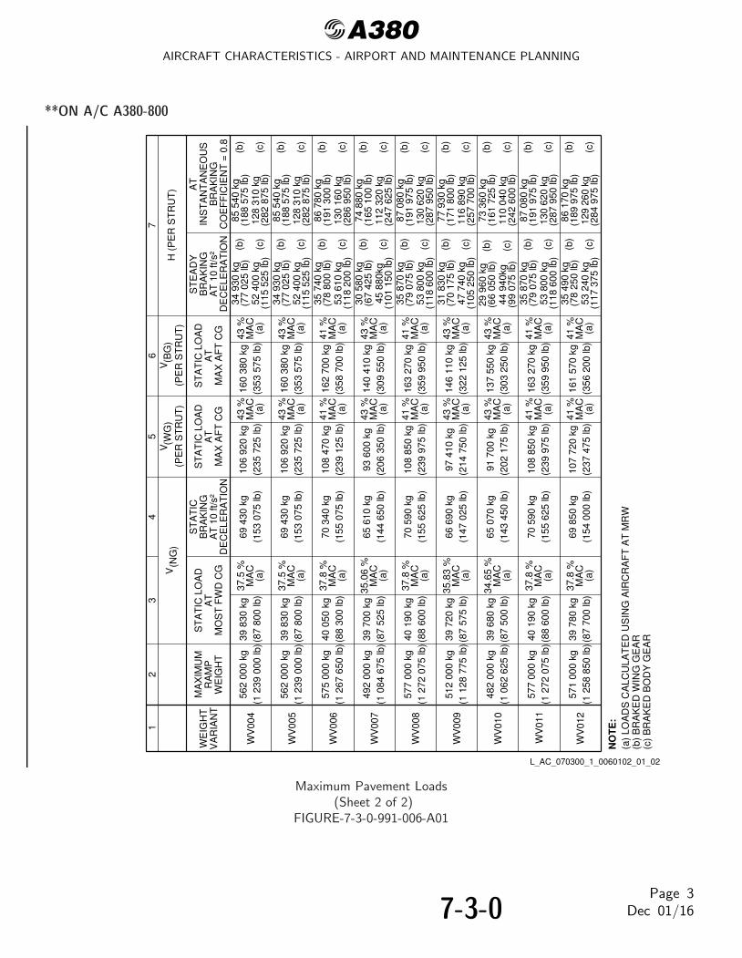
@A380AIRCRAFT CHARACTERISTICS - AIRPORT AND MAINTENANCE PLANNING
**ON A/C A380-800
NO
TE
:
12
34
56
(PE
R S
TR
UT
)
V(W
G)
H (
PE
R S
TR
UT
)V
(NG
)(P
ER
ST
RU
T)
V(B
G)
WV
004
WE
IGH
TV
AR
IAN
T
MA
XIM
UM
RA
MP
WE
IGH
TA
TS
TA
TIC
LO
AD
MO
ST
FW
D C
GA
T 1
0 ft/
s²D
EC
ELE
RA
TIO
N
BR
AK
ING
ST
AT
IC
AT
ST
AT
IC L
OA
D
MA
X A
FT
CG
BR
AK
ING
CO
EF
FIC
IEN
T =
0.8
INS
TA
NT
AN
EO
US
AT
AT
ST
AT
IC L
OA
D
MA
X A
FT
CG
AT
10
ft/s²
DE
CE
LER
AT
ION
BR
AK
ING
ST
EA
DY
562
000
kg(1
239
000
lb)
106
920
kg(2
35 7
25 lb
)16
0 38
0 kg
(353
575
lb)
37.5
%M
AC
(a)
43 %
MA
C(a
)
39 8
30 k
g(8
7 80
0 lb
)69
430
kg
(153
075
lb)
43 %
MA
C(a
)
34 9
30 k
g(7
7 02
5 lb
)52
400
kg
(115
525
lb)
(c)
(b)
108
470
kg(2
39 1
25 lb
)16
2 70
0 kg
(358
700
lb)
93 6
00 k
g(2
06 3
50 lb
)14
0 41
0 kg
(309
550
lb)
37.8
%M
AC
(a)
35.0
6 %
MA
C(a
)
41 %
MA
C(a
)
43 %
MA
C(a
)
WV
005
WV
006
WV
007
575
000
kg(1
267
650
lb)
492
000
kg(1
084
675
lb)
40 0
50 k
g(8
8 30
0 lb
)
39 7
00 k
g(8
7 52
5 lb
)
70 3
40 k
g(1
55 0
75 lb
)
65 6
10 k
g(1
44 6
50 lb
)
41 %
MA
C(a
)
43 %
MA
C(a
)
35 7
40 k
g(7
8 80
0 lb
)53
610
kg
(118
200
lb)
(c)
(b)
30 5
80 k
g(6
7 42
5 lb
)45
880
kg(1
01 1
50 lb
)(c
)
(b)
35 8
70 k
g(7
9 07
5 lb
)53
800
kg
(118
600
lb)
(c)
(b)
31 8
30 k
g(7
0 17
5 lb
)47
740
kg
(105
250
lb)
(c)
(b)
34 9
30 k
g(7
7 02
5 lb
)52
400
kg
(115
525
lb)
(c)
(b)
29 9
60 k
g(6
6 05
0 lb
)44
940
kg(9
9 07
5 lb
)(c
)
(b)
35 8
70 k
g(7
9 07
5 lb
)53
800
kg
(118
600
lb)
(c)
(b)
35 4
90 k
g(7
8 25
0 lb
)53
240
kg
(117
375
lb)
(c)
(b)
7
85 5
40 k
g(1
88 5
75 lb
)12
8 31
0 kg
(282
875
lb)
(c)
(b)
86 7
80 k
g(1
91 3
00 lb
)13
0 16
0 kg
(286
950
lb)
(c)
(b)
74 8
80 k
g(1
65 1
00 lb
)11
2 32
0 kg
(247
625
lb)
(c)
(b)
87 0
80 k
g(1
91 9
75 lb
)13
0 62
0 kg
(287
950
lb)
(c)
(b)
77 9
30 k
g(1
71 8
00 lb
)11
6 89
0 kg
(257
700
lb)
(c)
(b)
85 5
40 k
g(1
88 5
75 lb
)12
8 31
0 kg
(282
875
lb)
(c)
(b)
73 3
60 k
g(1
61 7
25 lb
)11
0 04
0 kg
(242
600
lb)
(c)
(b)
87 0
80 k
g(1
91 9
75 lb
)13
0 62
0 kg
(287
950
lb)
(c)
(b)
86 1
70 k
g(1
89 9
75 lb
)12
9 26
0 kg
(284
975
lb)
(c)
(b)
108
850
kg(2
39 9
75 lb
)16
3 27
0 kg
(359
950
lb)
97 4
10 k
g(2
14 7
50 lb
)14
6 11
0 kg
(322
125
lb)
37.8
%M
AC
(a)
35.8
3 %
MA
C(a
)
41 %
MA
C(a
)
43 %
MA
C(a
)
WV
008
WV
009
577
000
kg(1
272
075
lb)
512
000
kg(1
128
775
lb)
40 1
90 k
g(8
8 60
0 lb
)
39 7
20 k
g(8
7 57
5 lb
)
70 5
90 k
g(1
55 6
25 lb
)
66 6
90 k
g(1
47 0
25 lb
)
41 %
MA
C(a
)
43 %
MA
C(a
)
562
000
kg(1
239
000
lb)
106
920
kg(2
35 7
25 lb
)16
0 38
0 kg
(353
575
lb)
37.5
%M
AC
(a)
43 %
MA
C(a
)
39 8
30 k
g(8
7 80
0 lb
)69
430
kg
(153
075
lb)
43 %
MA
C(a
)
91 7
00 k
g(2
02 1
75 lb
)13
7 55
0 kg
(303
250
lb)
34.6
5 %
MA
C(a
)
43 %
MA
C(a
)W
V01
048
2 00
0 kg
(1 0
62 6
25 lb
)39
680
kg
(87
500
lb)
65 0
70 k
g(1
43 4
50 lb
)
43 %
MA
C(a
)
108
850
kg(2
39 9
75 lb
)16
3 27
0 kg
(359
950
lb)
107
720
kg(2
37 4
75 lb
)16
1 57
0 kg
(356
200
lb)
37.8
%M
AC
(a)
37.8
%M
AC
(a)
41 %
MA
C(a
)
41 %
MA
C(a
)
WV
011
WV
012
577
000
kg(1
272
075
lb)
571
000
kg(1
258
850
lb)
40 1
90 k
g(8
8 60
0 lb
)
39 7
80 k
g(8
7 70
0 lb
)
70 5
90 k
g(1
55 6
25 lb
)
69 8
50 k
g(1
54 0
00 lb
)
41 %
MA
C(a
)
41 %
MA
C(a
)
(a)
LOA
DS
CA
LCU
LAT
ED
US
ING
AIR
CR
AF
T A
T M
RW
(b)
BR
AK
ED
WIN
G G
EA
R(c
) B
RA
KE
D B
OD
Y G
EA
R
L_AC_070300_1_0060102_01_02
Maximum Pavement Loads(Sheet 2 of 2)
FIGURE-7-3-0-991-006-A01
7-3-0Page 3
Dec 01/16

@A380AIRCRAFT CHARACTERISTICS - AIRPORT AND MAINTENANCE PLANNING
7-4-0 Landing Gear Loading on Pavement
**ON A/C A380-800
Landing Gear Loading on Pavement
1. This section provides data about the landing gear loading on pavement.The MLG loading on pavement graphs are given for the weight variants that produce (at the MRWand maximum aft CG) the lowest MLG load and the highest MLG load for each type of aircraft.
2. MLG Loading on PavementExample, see FIGURE 7-4-0-991-001-A (Sheet 1), calculation of the total weight on the MLG for:- An aircraft with a MRW of 482 000 kg (1 062 625 lb),- The aircraft gross weight is 420 000 kg (925 950 lb),- A percentage of weight on the MLG of 95.1% (percentage of weight on the MLG at MRW and
maximum aft CG).The total weight on the MLG group is 399 530 kg (880 800 lb).
3. Wing Gear and Body Gear Loading on PavementThe MLG group consists of two wing gears (4-wheel bogies) plus two body gears (6-wheel bogies).
Example, see FIGURE 7-4-0-991-001-A (Sheet 2), calculation of the total weight on the MLG for:- An aircraft with a MRW of 482 000 kg (1 062 625 lb),- The aircraft gross weight is 420 000 kg (925 950 lb).The load on the two wing gears is 159 810 kg (352 325 lb) and the load on the two body gears is239 720 kg (528 475 lb).The total weight on the MLG group is 399 530 kg (880 800 lb).
NOTE : The CG in the figure title is the CG used for ACN/LCN calculation.
7-4-0Page 1
Dec 01/16

@A380AIRCRAFT CHARACTERISTICS - AIRPORT AND MAINTENANCE PLANNING
**ON A/C A380-800
100989694929088260270280290300310320330340350360370380390400410420430440450460470480490500510520530540550560570580590600
260270280290300310320330340350360370380390400410420430440450460470480490500510520530540550560570580590600
30 35 40 45 50 55
WE
IGH
T O
N M
AIN
LA
ND
ING
GE
AR
(x
1 00
0 kg
)
(x 1
000
kg)
PERCENTAGE OF WEIGHT ON MAIN GEAR
PERCENTAGE MAC
600
650
700
750
800
850
900
950
1 000
1 050
1 100
1 150
1 200
1 250
1 300
(x 1
000
lb)
AIR
CR
AF
T G
RO
SS
WE
IGH
T
CG FOR ACN/LCNCALCULATION
43% MAC
MZFW
TAKE OFF
MLW
MTOW − 480 000 kg
LANDING
34.65% MAC
L_AC_070400_1_0010101_01_01
Landing Gear Loading on PavementWV010, MRW 482 000 kg, CG 43% (Sheet 1 of 2)
FIGURE-7-4-0-991-001-A01
7-4-0Page 2
Dec 01/16

@A380AIRCRAFT CHARACTERISTICS - AIRPORT AND MAINTENANCE PLANNING
**ON A/C A380-800
100
120
140
160
180
200
220
240
260
280
300
320
340 26
028
030
032
034
036
038
040
042
044
046
048
050
052
054
056
058
060
0
LOAD ON CENTER GEARS OR LOAD ON WING GEARS (x 1 000 kg)
AIR
CR
AF
T G
RO
SS
WE
IGH
T (
x 1
000
kg)
600
700
800
900
1 00
01
100
1 20
01
300
(x 1
000
lb)
300
400
500
600
700
(x 1 000 lb)
WIN
G G
EA
RS
BO
DY
GE
AR
S
L_AC_070400_1_0010102_01_01
Landing Gear Loading on PavementWV010, MRW 482 000 kg, CG 43% (Sheet 2 of 2)
FIGURE-7-4-0-991-001-A01
7-4-0Page 3
Dec 01/16

@A380AIRCRAFT CHARACTERISTICS - AIRPORT AND MAINTENANCE PLANNING
**ON A/C A380-800
100989694929088260270280290300310320330340350360370380390400410420430440450460470480490500510520530540550560570580590600
260270280290300310320330340350360370380390400410420430440450460470480490500510520530540550560570580590600
30 35 40 45 50 55
WE
IGH
T O
N M
AIN
LA
ND
ING
GE
AR
(x
1 00
0 kg
)
(x 1
000
kg)
PERCENTAGE OF WEIGHT ON MAIN GEAR
PERCENTAGE MAC
600
650
700
750
800
850
900
950
1 000
1 050
1 100
1 150
1 200
1 250
1 300
(x 1
000
lb)
AIR
CR
AF
T G
RO
SS
WE
IGH
T
37.8% MAC
MTOW − 575 000 kgCG FOR ACN/LCN
CALCULATION41% MAC
MLW
MZFW
TAKE OFF
LANDING
L_AC_070400_1_0020101_01_00
Landing Gear Loading on PavementWV008, MRW 577 000 kg, CG 41% (Sheet 1 of 2)
FIGURE-7-4-0-991-002-A01
7-4-0Page 4
Dec 01/16
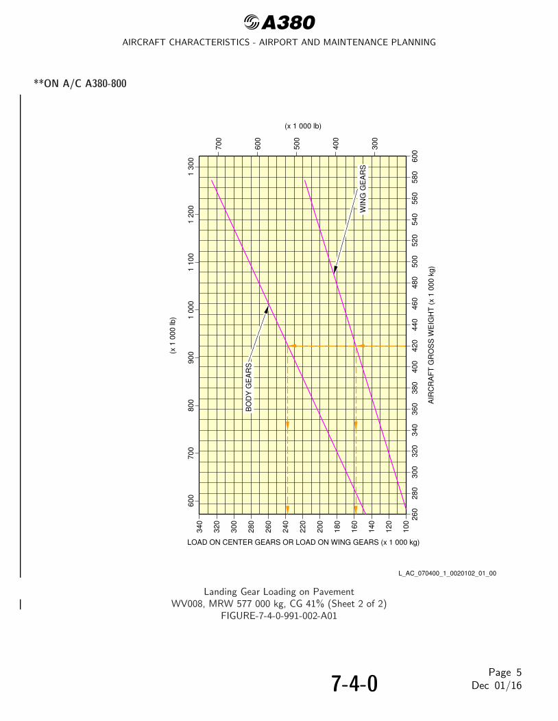
@A380AIRCRAFT CHARACTERISTICS - AIRPORT AND MAINTENANCE PLANNING
**ON A/C A380-800
100
120
140
160
180
200
220
240
260
280
300
320
340 26
028
030
032
034
036
038
040
042
044
046
048
050
052
054
056
058
060
0
LOAD ON CENTER GEARS OR LOAD ON WING GEARS (x 1 000 kg)
AIR
CR
AF
T G
RO
SS
WE
IGH
T (
x 1
000
kg)
600
700
800
900
1 00
01
100
1 20
01
300
(x 1
000
lb)
300
400
500
600
700
(x 1 000 lb)
BO
DY
GE
AR
S
WIN
G G
EA
RS
L_AC_070400_1_0020102_01_00
Landing Gear Loading on PavementWV008, MRW 577 000 kg, CG 41% (Sheet 2 of 2)
FIGURE-7-4-0-991-002-A01
7-4-0Page 5
Dec 01/16
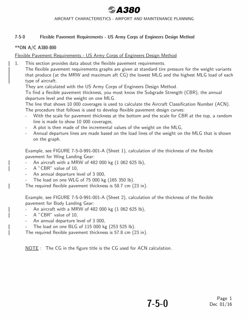
@A380AIRCRAFT CHARACTERISTICS - AIRPORT AND MAINTENANCE PLANNING
7-5-0 Flexible Pavement Requirements - US Army Corps of Engineers Design Method
**ON A/C A380-800
Flexible Pavement Requirements - US Army Corps of Engineers Design Method
1. This section provides data about the flexible pavement requirements.The flexible pavement requirements graphs are given at standard tire pressure for the weight variantsthat produce (at the MRW and maximum aft CG) the lowest MLG and the highest MLG load of eachtype of aircraft.They are calculated with the US Army Corps of Engineers Design Method.To find a flexible pavement thickness, you must know the Subgrade Strength (CBR), the annualdeparture level and the weight on one MLG.The line that shows 10 000 coverages is used to calculate the Aircraft Classification Number (ACN).The procedure that follows is used to develop flexible pavement design curves:- With the scale for pavement thickness at the bottom and the scale for CBR at the top, a random
line is made to show 10 000 coverages,- A plot is then made of the incremental values of the weight on the MLG,- Annual departure lines are made based on the load lines of the weight on the MLG that is shown
on the graph.
Example, see FIGURE 7-5-0-991-001-A (Sheet 1), calculation of the thickness of the flexiblepavement for Wing Landing Gear:- An aircraft with a MRW of 482 000 kg (1 062 625 lb),- A ”CBR” value of 10,- An annual departure level of 3 000,- The load on one WLG of 75 000 kg (165 350 lb).The required flexible pavement thickness is 58.7 cm (23 in).
Example, see FIGURE 7-5-0-991-001-A (Sheet 2), calculation of the thickness of the flexiblepavement for Body Landing Gear:- An aircraft with a MRW of 482 000 kg (1 062 625 lb),- A ”CBR” value of 10,- An annual departure level of 3 000,- The load on one BLG of 115 000 kg (253 525 lb).The required flexible pavement thickness is 57.8 cm (23 in).
NOTE : The CG in the figure title is the CG used for ACN calculation.
7-5-0Page 1
Dec 01/16

@A380AIRCRAFT CHARACTERISTICS - AIRPORT AND MAINTENANCE PLANNING
**ON A/C A380-800
10 000 COVERAGES USED
SUBGRADE STRENGTH − CBR
8060403020151063
8060403020151063
FLEXIBLE PAVEMENT THICKNESS
1 400 x 530 R23 40PR TIRES
TIRE PRESSURE CONSTANT AT 15 bar (218 psi)
10 15 20 30 40 60 80 100 120 150 180
FOR ACN CALCULATIONS
(cm)
(in)
WEIGHT ON ONE WING LANDING GEAR91 700 kg (202 175 lb)
60 000 kg (132 275 lb)45 000 kg (99 200 lb)30 000 kg (66 150 lb)
75 000 kg (165 350 lb)
ALPHA FACTOR = 0.8
1 2003 0006 00015 000
ANNUAL DEPARTURES*
*20 YEAR PAVEMENT LIFE25 000
MAXIMUM POSSIBLE WINGLANDING GEAR LOAD ATMAXIMUM RAMP WEIGHTAND AFT CG
L_AC_070500_1_0010101_01_01
Flexible Pavement RequirementsWV010, MRW 482 000 kg, CG 43% - Wing Landing Gear (Sheet 1 of 2)
FIGURE-7-5-0-991-001-A01
7-5-0Page 2
Dec 01/16

@A380AIRCRAFT CHARACTERISTICS - AIRPORT AND MAINTENANCE PLANNING
**ON A/C A380-800
10 000 COVERAGES USED
MAXIMUM POSSIBLE BODYLANDING GEAR LOAD ATMAXIMUM RAMP WEIGHT
SUBGRADE STRENGTH − CBR
8060403020151063
8060403020151063
FLEXIBLE PAVEMENT THICKNESS
1 400 x 530 R23 40PR TIRES
TIRE PRESSURE CONSTANT AT 15 bar (218 psi)
10 15 20 30 40 60 80 100 120 150 180
FOR ACN CALCULATIONS
AND AFT CG
(cm)
(in)
1 2003 0006 00015 000
ANNUAL DEPARTURES*
*20 YEAR PAVEMENT LIFE25 000
WEIGHT ON ONE BODY LANDING GEAR137 550 kg (303 250 lb)
100 000 kg (220 450 lb)85 000 kg (187 400 lb)70 000 kg (154 325 lb)
115 000 kg (253 525 lb)
ALPHA FACTOR = 0.72
L_AC_070500_1_0010102_01_01
Flexible Pavement RequirementsWV010, MRW 482 000 kg, CG 43% - Body Landing Gear (Sheet 2 of 2)
FIGURE-7-5-0-991-001-A01
7-5-0Page 3
Dec 01/16

@A380AIRCRAFT CHARACTERISTICS - AIRPORT AND MAINTENANCE PLANNING
**ON A/C A380-800
10 000 COVERAGES USED
MAXIMUM POSSIBLE WINGLANDING GEAR LOAD ATMAXIMUM RAMP WEIGHT
SUBGRADE STRENGTH − CBR
8060403020151063
8060403020151063
FLEXIBLE PAVEMENT THICKNESS
1 400 x 530 R23 40PR TIRES
TIRE PRESSURE CONSTANT AT 15 bar (218 psi)
10 15 20 30 40 60 80 100 120 150 180
FOR ACN CALCULATIONSALPHA FACTOR = 0.8
AND AFT CG
1 2003 0006 00015 000
ANNUAL DEPARTURES*
*20 YEAR PAVEMENT LIFE25 000
WEIGHT ON ONE WING LANDING GEAR108 850 kg (239 975 lb)
70 000 kg (154 325 lb)55 000 kg (121 250 lb)40 000 kg (88 175 lb)
85 000 kg (187 400 lb)
(cm)
(in)
L_AC_070500_1_0020101_01_00
Flexible Pavement RequirementsWV008, MRW 577 000 kg, CG 41% - Wing Landing Gear (Sheet 1 of 2)
FIGURE-7-5-0-991-002-A01
7-5-0Page 4
Dec 01/16

@A380AIRCRAFT CHARACTERISTICS - AIRPORT AND MAINTENANCE PLANNING
**ON A/C A380-800
10 000 COVERAGES USED
SUBGRADE STRENGTH − CBR
8060403020151063
8060403020151063
(cm)
FLEXIBLE PAVEMENT THICKNESS
1 400 x 530 R23 40PR TIRES
TIRE PRESSURE CONSTANT AT 15 bar (218 psi)
10 15 20 30 40 60 80 100 120 150 180
(in)
FOR ACN CALCULATIONSALPHA FACTOR = 0.72
1 2003 0006 00015 000
ANNUAL DEPARTURES*
*20 YEAR PAVEMENT LIFE25 000
MAXIMUM POSSIBLE BODYLANDING GEAR LOAD ATMAXIMUM RAMP WEIGHTAND AFT CG
WEIGHT ON ONE BODY LANDING GEAR163 270 kg (359 950 lb)
130 000 kg (286 600 lb)115 000 kg (253 525 lb)100 000 kg (220 450 lb)
145 000 kg (319 675 lb)
L_AC_070500_1_0020102_01_00
Flexible Pavement RequirementsWV008, MRW 577 000 kg, CG 41% - Body Landing Gear (Sheet 2 of 2)
FIGURE-7-5-0-991-002-A01
7-5-0Page 5
Dec 01/16

@A380AIRCRAFT CHARACTERISTICS - AIRPORT AND MAINTENANCE PLANNING
7-6-0 Flexible Pavement Requirements - LCN Conversion
**ON A/C A380-800
Flexible Pavement Requirements - LCN Conversion
1. The Load Classification Number (LCN) curves are no longer provided in section 07-06-00 since theLCN system for reporting pavement strength is obsolete, having been replaced by the ICAOrecommended ACN/PCN system in 1983.For questions regarding the LCN system, contact Airbus.
7-6-0Page 1
Dec 01/16

@A380AIRCRAFT CHARACTERISTICS - AIRPORT AND MAINTENANCE PLANNING
7-7-0 Rigid Pavement Requirements - Portland Cement Association Design Method
**ON A/C A380-800
Rigid Pavement Requirements - Portland Cement Association Design Method
1. This section provides data about the rigid pavement requirements for the PCA (Portland CementAssociation) design method.The rigid pavement requirement graphs are given at standard tire pressure for the weight variantsproducing (at the MRW and maximum aft CG) the lowest MLG load and the highest MLG load foreach type of aircraft.They are calculated with the PCA design method.To find a rigid pavement thickness, you must know the Subgrade Modulus (k), the permitted workingstress and the weight on one MLG.The procedure that follows is used to develop rigid pavement design curves:- With the scale for pavement thickness on the left and the scale for permitted working stress on
the right, a random load line is made. This represents the MLG maximum weight to be shown,- A plot is then made of all values of the subgrade modulus (k values),- More load lines for the incremental values of the weight on the MLG are made based on the
curve for k = 80 MN/m3, which is already shown on the graph.
Example, see FIGURE 7-7-0-991-001-A (Sheet 1), calculation of the thickness of the rigid pavementfor the WLG:- An aircraft with a MRW of 482 000 kg (1 062 625 lb),- A k value of 80 MN/m3 (300 lbf/in3),- A permitted working stress of 38.67 kg/cm2 (550 lb/in2),- The load on one MLG is 75 000 kg (165 350 lb).The required rigid pavement thickness is 227 mm (9 in).
Example, see FIGURE 7-7-0-991-001-A (Sheet 2), calculation of the thickness of the rigid pavementfor the BLG:- An aircraft with a MRW of 482 000 kg (1 062 625 lb),- A k value of 80 MN/m3 (300 lbf/in3),- A permitted working stress of 38.67 kg/cm2 (550 lb/in2),- The load on one MLG is 115 000 kg (253 525 lb).The required rigid pavement thickness is 231 mm (9 in).
NOTE : The CG in the figure title is the CG used for ACN calculation.
7-7-0Page 1
Dec 01/16

@A380AIRCRAFT CHARACTERISTICS - AIRPORT AND MAINTENANCE PLANNING
**ON A/C A380-800
1 400 x 530 R23 40PR TIRESTIRE PRESSURE CONSTANT AT 15 bar (218 psi)
100
200
300
400
500
600
700
800
90015
14
13
12
11
10
9
7
8
FOR LOADS LESS THAN MAXIMUM,EXACT.LINE AND ANY VALUES FOR k ARETHE MAXIMUM LOAD REFERENCETHE VALUES OBTAINED BY USINGNOTE:
THE CURVES ARE EXACT FOR k =80 MN/m³ BUT DEVIATE SLIGHTLYFOR ANY OTHER VALUES OF k.
PDILB" PORTLAND CEMENTPAVEMENT DESIGN − PROGRAMPROGRAM FOR AIRPORTPAVEMENTS" AND "COMPUTER"DESIGN OF CONCRETE AIRPORTREFERENCE:
ASSOCIATION.
k = 150 MN/m³k = 80 MN/m³k = 40 MN/m³k = 20 MN/m³
45 000 kg60 000 kg75 000 kg91 700 kg
LANDING GEARWEIGHT ON ONE WING
30 000 kg
(165 350 lb)(132 275 lb)
(99 200 lb)(66 150 lb)
GEAR LOAD AT MAXIMUMMAXIMUM POSSIBLE WING
RAMP WEIGHT AND AFT CG
(202 175 lb)
60
50
40
30
20
10
38
36
34
32
30
28
26
24
22
20
18(k
g/cm
²)
ALL
OW
AB
LE W
OR
KIN
G S
TR
ES
S
(lb/in
²)
RIG
ID P
AV
EM
EN
T T
HIC
KN
ES
S(c
m)
(in)
L_AC_070700_1_0010101_01_01
Rigid Pavement RequirementsWV010, MRW 482 000 kg, CG 43% - WLG (Sheet 1 of 2)
FIGURE-7-7-0-991-001-A01
7-7-0Page 2
Dec 01/16

@A380AIRCRAFT CHARACTERISTICS - AIRPORT AND MAINTENANCE PLANNING
**ON A/C A380-800
1 400 x 530 R23 40PR TIRESTIRE PRESSURE CONSTANT AT 15 bar (218 psi)
100
200
300
400
500
600
700
800
90015
14
13
12
11
10
9
7
8
FOR LOADS LESS THAN MAXIMUM,EXACT.LINE AND ANY VALUES FOR k ARETHE MAXIMUM LOAD REFERENCETHE VALUES OBTAINED BY USINGNOTE:
THE CURVES ARE EXACT FOR k =80 MN/m³ BUT DEVIATE SLIGHTLYFOR ANY OTHER VALUES OF k.
PDILB" PORTLAND CEMENTPAVEMENT DESIGN − PROGRAMPROGRAM FOR AIRPORTPAVEMENTS" AND "COMPUTER"DESIGN OF CONCRETE AIRPORTREFERENCE:
ASSOCIATION.
k = 150 MN/m³k = 80 MN/m³k = 40 MN/m³k = 20 MN/m³
85 000 kg100 000 kg115 000 kg137 550 kgLANDING GEARWEIGHT ON ONE BODY
70 000 kg
(253 525 lb)(220 450 lb)(187 400 lb)(154 325 lb)
(303 250 lb)
60
50
40
30
20
10
38
36
34
32
30
28
26
24
22
20
18(k
g/cm
²)
ALL
OW
AB
LE W
OR
KIN
G S
TR
ES
S
(lb/in
²)
RIG
ID P
AV
EM
EN
T T
HIC
KN
ES
S(c
m)
(in)
GEAR LOAD AT MAXIMUMMAXIMUM POSSIBLE BODY
RAMP WEIGHT AND AFT CG
L_AC_070700_1_0010102_01_01
Rigid Pavement RequirementsWV010, MRW 482 000 kg, CG 43% - BLG (Sheet 2 of 2)
FIGURE-7-7-0-991-001-A01
7-7-0Page 3
Dec 01/16

@A380AIRCRAFT CHARACTERISTICS - AIRPORT AND MAINTENANCE PLANNING
**ON A/C A380-800
1 400 x 530 R23 40PR TIRESTIRE PRESSURE CONSTANT AT 15 bar (218 psi)
60
50
40
30
20
10
100
200
300
400
500
600
700
800
90015
14
38
36
34
32
13
1230
28 11
26
24
22
10
9
20
18 7
8
(kg/
cm²)
ALL
OW
AB
LE W
OR
KIN
G S
TR
ES
S
(lb/in
²)
RIG
ID P
AV
EM
EN
T T
HIC
KN
ES
S(c
m)
(in)
FOR LOADS LESS THAN MAXIMUM,EXACT.LINE AND ANY VALUES FOR k ARETHE MAXIMUM LOAD REFERENCETHE VALUES OBTAINED BY USINGNOTE:
THE CURVES ARE EXACT FOR k =80 MN/m³ BUT DEVIATE SLIGHTLYFOR ANY OTHER VALUES OF k.
PDILB" PORTLAND CEMENTPAVEMENT DESIGN − PROGRAMPROGRAM FOR AIRPORTPAVEMENTS" AND "COMPUTER"DESIGN OF CONCRETE AIRPORTREFERENCE:
ASSOCIATION.
55 000 kg70 000 kg85 000 kg
108 850 kg (239 975 lb)LANDING GEARWEIGHT ON ONE WING
40 000 kg
k = 150 MN/m³k = 80 MN/m³k = 40 MN/m³k = 20 MN/m³
GEAR LOAD AT MAXIMUMMAXIMUM POSSIBLE WING
RAMP WEIGHT AND AFT CG
(187 400 lb)(154 325 lb)(121 250 lb)
(88 175 lb)
L_AC_070700_1_0020101_01_00
Rigid Pavement RequirementsWV008, MRW 577 000 kg, CG 41% - WLG (Sheet 1 of 2)
FIGURE-7-7-0-991-002-A01
7-7-0Page 4
Dec 01/16

@A380AIRCRAFT CHARACTERISTICS - AIRPORT AND MAINTENANCE PLANNING
**ON A/C A380-800
1 400 x 530 R23 40PR TIRESTIRE PRESSURE CONSTANT AT 15 bar (218 psi)
60
50
40
30
20
10
100
200
300
400
500
600
700
800
90015
14
38
36
34
32
13
1230
28 11
26
24
22
10
9
20
18 7
8
(kg/
cm²)
ALL
OW
AB
LE W
OR
KIN
G S
TR
ES
S
(lb/in
²)
RIG
ID P
AV
EM
EN
T T
HIC
KN
ES
S(c
m)
(in)
FOR LOADS LESS THAN MAXIMUM,EXACT.LINE AND ANY VALUES FOR k ARETHE MAXIMUM LOAD REFERENCETHE VALUES OBTAINED BY USINGNOTE:
THE CURVES ARE EXACT FOR k =80 MN/m³ BUT DEVIATE SLIGHTLYFOR ANY OTHER VALUES OF k.
PDILB" PORTLAND CEMENTPAVEMENT DESIGN − PROGRAMPROGRAM FOR AIRPORTPAVEMENTS" AND "COMPUTER"DESIGN OF CONCRETE AIRPORTREFERENCE:
ASSOCIATION.
k = 150 MN/m³k = 80 MN/m³k = 40 MN/m³k = 20 MN/m³
115 000 kg (253 525 lb)130 000 kg (286 600 lb)145 000 kg (319 675 lb)163 270 kg (359 950 lb)LANDING GEARWEIGHT ON ONE BODY
100 000 kg (220 450 lb)
GEAR LOAD AT MAXIMUMMAXIMUM POSSIBLE BODY
RAMP WEIGHT AND AFT CG
L_AC_070700_1_0020102_01_00
Rigid Pavement RequirementsWV008, MRW 577 000 kg, CG 41% - BLG (Sheet 2 of 2)
FIGURE-7-7-0-991-002-A01
7-7-0Page 5
Dec 01/16

@A380AIRCRAFT CHARACTERISTICS - AIRPORT AND MAINTENANCE PLANNING
7-8-0 Rigid Pavement Requirements - LCN Conversion
**ON A/C A380-800
Rigid Pavement Requirements - LCN Conversion
1. The Load Classification Number (LCN) curves are no longer provided in section 07-08-00 since theLCN system for reporting pavement strength is obsolete, having been replaced by the ICAOrecommended ACN/PCN system in 1983.For questions regarding the LCN system, contact Airbus.
7-8-0Page 1
Dec 01/16

@A380AIRCRAFT CHARACTERISTICS - AIRPORT AND MAINTENANCE PLANNING
7-9-0 ACN/PCN Reporting System - Flexible and Rigid Pavements
**ON A/C A380-800
ACN/PCN Reporting System - Flexible and Rigid Pavements
1. This section provides data about the Aircraft Classification Number (ACN) for an aircraft grossweight in relation to a subgrade strength value for flexible and rigid pavement.The flexible and rigid pavement requirements graphs are given at standard tire pressure for theweight variants producing (at the MRW and maximum aft CG) the lowest MLG load and the highestMLG load for each type of aircraft.To find the ACN of an aircraft on flexible and rigid pavement, you must know the aircraft grossweight and the subgrade strength.
NOTE : An aircraft with an ACN equal to or less than the reported PCN can operate on thatpavement, subject to any limitation on the tire pressure.(Ref: ICAO Aerodrome Design Manual, Part 3, Chapter 1, Second Edition 1983).
Example, see FIGURE 7-9-0-991-002-A (Sheet 1), calculation of the ACN for flexible pavement for:- An aircraft with a MRW of 482 000 kg (1 062 625 lb),- An aircraft gross weight of 420 000 kg (925 950 lb),- A medium subgrade strength (code B).The ACN for flexible pavement is 44.
Example, see FIGURE 7-9-0-991-002-A (Sheet 2), calculation of the ACN for rigid pavement for:- An aircraft with a MRW of 482 000 kg (1 062 625 lb),- An aircraft gross weight of 420 000 kg (925 950 lb),- A medium subgrade strength (code B).The ACN for rigid pavement is 45.
2. Aircraft Classification Number - ACN tableThe table in FIGURE 7-9-0-991-001-A provide ACN data in tabular format similar to the one used byICAO in the ”Aerodrome Design Manual Part 3, Pavements - Edition 1983” for all the operationalweight variants of the aircraft.As an approximation, use a linear interpolation in order to get the ACN at the required operatingweight using the following equation:- ACN = ACN min + (ACN max - ACN min) x (Operating weight - 300 000 kg)/(MRW - 300 000
kg)As an approximation, also use a linear interpolation in order to get the aircraft weight at thepavement PCN using the following equation:- Operating weight = 300 000 kg + (MRW - 300 000 kg) x (PCN - ACN min)/(ACN max - ACN
min)With ACN max = ACN calculated at the MRW in the table and with ACN min = ACN calculated at300 000 kg.
7-9-0Page 1
Dec 01/16

@A380AIRCRAFT CHARACTERISTICS - AIRPORT AND MAINTENANCE PLANNING
NOTE : The CG in the figure title is the CG used for ACN calculation.
7-9-0Page 2
Dec 01/16

@A380AIRCRAFT CHARACTERISTICS - AIRPORT AND MAINTENANCE PLANNING
**ON A/C A380-800
WV000
ALL UPMASS
(kg)
LOAD ONONE MAINGEAR LEG
(%)
TIREPRESSURE
(MPa)
562 00019 (WLG)
28.5 (BLG)
300 00019 (WLG)
28.5 (BLG)
1.50
5655
ACN FORRIGID PAVEMENT
SUBGRADES−MN/m³
ACN FORFLEXIBLE PAVEMENT
SUBGRADES−CBR
HIGH150
MEDIUM80
LOW40
ULTRA−LOW20 15
HIGH10
MEDIUM6
LOW3
ULTRA−LOW
6668
7888
91110
5956
6462
7575
102106
27 2929
3434
3942
2725
2927
31 4029 30 40
512 00019 (WLG)
28.5 (BLG)
300 00019 (WLG)
28.5 (BLG)
1.40
4948
5757
6875
7994
5149
5654
6665
9092
26 2928
3333
3842
2725
2827
31 4028 30 40
571 00018.9 (WLG)28.3 (BLG)
300 00018.9 (WLG)28.3 (BLG)
1.50
5756
6769
7989
91111
5957
6463
7676
104107
27 2929
3334
3842
2725
2826
31 4028 30 39
512 00019 (WLG)
28.5 (BLG)
300 00019 (WLG)
28.5 (BLG)
1.40
4948
5757
6875
7994
5149
5654
6665
9092
26 2928
3333
3842
2725
2827
31 4028 30 40
562 00019 (WLG)
28.5 (BLG)
300 00019 (WLG)
28.5 (BLG)
1.50
5655
6668
7888
91110
5956
6462
7575
102106
27 2929
3434
3942
2725
2927
31 4029 30 40
562 00019 (WLG)
28.5 (BLG)
300 00019 (WLG)
28.5 (BLG)
1.50
5655
6668
7888
91110
5956
6462
7575
102106
27 2929
3434
3942
2725
2927
31 4029 30 40
575 00018.9 (WLG)28.3 (BLG)18.9 (WLG)28.3 (BLG)
1.50
5856
6769
8090
92113
6057
6563
7777
105108
27 2929
3334
3842
2725
2826
31 4028 30 39
19 (WLG)28.5 (BLG)19 (WLG)
28.5 (BLG)
1.40
4646
5454
6470
7589
4947
5351
6261
8587
26 2928
3333
3842
2725
2827
31 4028 30 40
18.9 (WLG)28.3 (BLG)18.9 (WLG)28.3 (BLG)
1.50
5856
6870
8091
93113
6058
6564
7777
105108
27 2929
3334
3842
2725
2826
31 4028 30 39
19 (WLG)28.5 (BLG)19 (WLG)
28.5 (BLG)
1.50
5050
5859
6976
8096
5249
5654
6665
9092
27 2929
3434
3942
2725
2927
31 4029 30 40
WEIGHTVARIANT
WV001
WV002
WV003
WV004
WV005
WV006
WV007
WV008
WV009300 000
512 000
300 000
577 000
300 000
300 000
492 000
L_AC_070900_1_0010101_01_02
Aircraft Classification NumberACN Table (Sheet 1 of 2)
FIGURE-7-9-0-991-001-A01
7-9-0Page 3
Dec 01/16

@A380AIRCRAFT CHARACTERISTICS - AIRPORT AND MAINTENANCE PLANNING
**ON A/C A380-800
WV010
ALL UPMASS
(kg)
LOAD ONONE MAINGEAR LEG
(%)
TIREPRESSURE
(MPa)
482 00019 (WLG)
28.5 (BLG)
300 00019 (WLG)
28.5 (BLG)
1.50
4746
ACN FORRIGID PAVEMENT
SUBGRADES−MN/m³
ACN FORFLEXIBLE PAVEMENT
SUBGRADES−CBR
HIGH150
MEDIUM80
LOW40
ULTRA−LOW20 15
HIGH10
MEDIUM6
LOW3
ULTRA−LOW
5454
6369
7487
4845
5250
6059
8384
27 2929
3434
3942
2725
2927
31 4029 30 40
WEIGHTVARIANT
WV011577 000
18.9 (WLG)28.3 (BLG)
300 00018.9 (WLG)28.3 (BLG)
1.50
5856
6870
8091
93113
6058
6564
7777
105108
27 2929
3334
3842
2725
2826
31 4028 30 39
WV012571 000
18.9 (WLG)28.3 (BLG)
300 00018.9 (WLG)28.3 (BLG)
1.50
5756
6769
7989
91111
5957
6463
7676
104107
27 2929
3334
3842
2725
2826
31 4028 30 39
L_AC_070900_1_0010102_01_00
Aircraft Classification NumberACN Table (Sheet 2 of 2)
FIGURE-7-9-0-991-001-A01
7-9-0Page 4
Dec 01/16

@A380AIRCRAFT CHARACTERISTICS - AIRPORT AND MAINTENANCE PLANNING
**ON A/C A380-800
2030405060708090100
110
120
600
700
800
900
1 00
01
100
1 20
01
300
(x 1
000
lb)
TIR
E P
RE
SS
UR
E C
ON
ST
AN
T A
T 1
5 ba
r (2
18 p
si)
1 40
0 x
530
R23
40P
R T
IRE
SS
EE
SE
CT
ION
7−
4−0.
CH
AP
TE
R 1
. SE
CO
ND
ED
ITIO
N 1
983.
ICA
O A
ER
OD
RO
ME
DE
SIG
N M
AN
UA
L P
AR
T 3
AC
N W
AS
DE
TE
RM
INE
D A
S R
EF
ER
EN
CE
D IN
D −
CB
R
3 (
ULT
RA
LO
W)
SU
BG
RA
DE
ST
RE
NG
TH
C −
CB
R
6 (
LOW
)B
− C
BR
10
(ME
DIU
M)
A −
CB
R 1
5 (H
IGH
)
ALP
HA
FA
CT
OR
= 0
.72
FO
R B
LGA
LPH
A F
AC
TO
R =
0.8
FO
R W
LG
250
300
350
400
450
500
550
600
(x 1
000
kg)
AIR
CR
AF
T G
RO
SS
WE
IGH
T
AIRCRAFT CLASSIFICATION NUMBER (ACN)
L_AC_070900_1_0020101_01_01
Aircraft Classification NumberFlexible Pavement - WV010, MRW 482 000 kg, CG 43% (Sheet 1 of 2)
FIGURE-7-9-0-991-002-A01
7-9-0Page 5
Dec 01/16
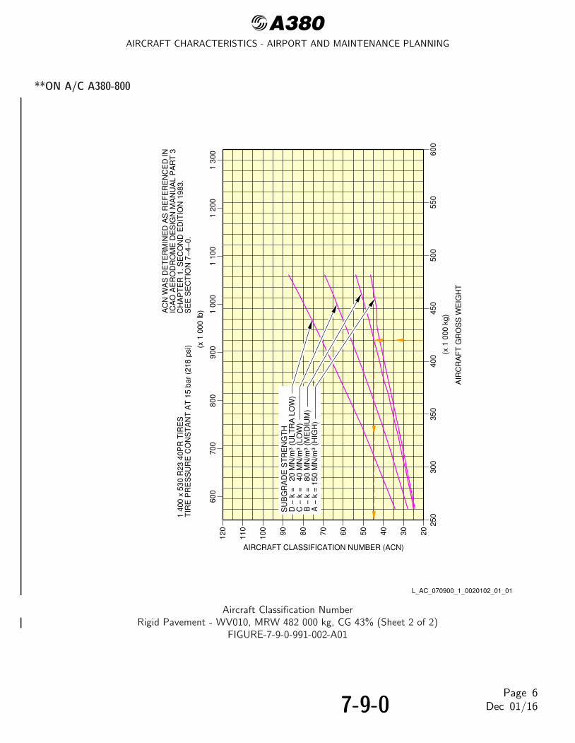
@A380AIRCRAFT CHARACTERISTICS - AIRPORT AND MAINTENANCE PLANNING
**ON A/C A380-800
250
2030405060708090100
110
120
600
700
800
900
1 00
01
100
1 20
0
300
350
400
1 30
0
450
500
550
600
(x 1
000
lb)
TIR
E P
RE
SS
UR
E C
ON
ST
AN
T A
T 1
5 ba
r (2
18 p
si)
1 40
0 x
530
R23
40P
R T
IRE
SS
EE
SE
CT
ION
7−
4−0.
(x 1
000
kg)
AIR
CR
AF
T G
RO
SS
WE
IGH
T
CH
AP
TE
R 1
. SE
CO
ND
ED
ITIO
N 1
983.
ICA
O A
ER
OD
RO
ME
DE
SIG
N M
AN
UA
L P
AR
T 3
AC
N W
AS
DE
TE
RM
INE
D A
S R
EF
ER
EN
CE
D IN
D −
k =
20
MN
/m³
(ULT
RA
LO
W)
SU
BG
RA
DE
ST
RE
NG
TH
C −
k =
40
MN
/m³
(LO
W)
B −
k =
80
MN
/m³
(ME
DIU
M)
A −
k =
150
MN
/m³
(HIG
H)
AIRCRAFT CLASSIFICATION NUMBER (ACN)
L_AC_070900_1_0020102_01_01
Aircraft Classification NumberRigid Pavement - WV010, MRW 482 000 kg, CG 43% (Sheet 2 of 2)
FIGURE-7-9-0-991-002-A01
7-9-0Page 6
Dec 01/16

@A380AIRCRAFT CHARACTERISTICS - AIRPORT AND MAINTENANCE PLANNING
**ON A/C A380-800
2030405060708090100
110
120
600
700
800
900
1 00
01
100
1 20
01
300
(x 1
000
lb)
TIR
E P
RE
SS
UR
E C
ON
ST
AN
T A
T 1
5 ba
r (2
18 p
si)
1 40
0 x
530
R23
40P
R T
IRE
SS
EE
SE
CT
ION
7−
4−0.
CH
AP
TE
R 1
. SE
CO
ND
ED
ITIO
N 1
983.
ICA
O A
ER
OD
RO
ME
DE
SIG
N M
AN
UA
L P
AR
T 3
AC
N W
AS
DE
TE
RM
INE
D A
S R
EF
ER
EN
CE
D IN
D −
CB
R
3 (
ULT
RA
LO
W)
SU
BG
RA
DE
ST
RE
NG
TH
C −
CB
R
6 (
LOW
)B
− C
BR
10
(ME
DIU
M)
A −
CB
R 1
5 (H
IGH
)
ALP
HA
FA
CT
OR
= 0
.72
FO
R B
LGA
LPH
A F
AC
TO
R =
0.8
FO
R W
LG
250
300
350
400
450
500
550
600
(x 1
000
kg)
AIR
CR
AF
T G
RO
SS
WE
IGH
T
AIRCRAFT CLASSIFICATION NUMBER (ACN)
L_AC_070900_1_0030101_01_00
Aircraft Classification NumberFlexible Pavement - WV008, MRW 577 000 kg, CG 41% (Sheet 1 of 2)
FIGURE-7-9-0-991-003-A01
7-9-0Page 7
Dec 01/16

@A380AIRCRAFT CHARACTERISTICS - AIRPORT AND MAINTENANCE PLANNING
**ON A/C A380-800
250
2030405060708090100
110
120
600
700
800
900
1 00
01
100
1 20
0
300
350
400
1 30
0
450
500
550
600
(x 1
000
lb)
TIR
E P
RE
SS
UR
E C
ON
ST
AN
T A
T 1
5 ba
r (2
18 p
si)
1 40
0 x
530
R23
40P
R T
IRE
SS
EE
SE
CT
ION
7−
4−0.
(x 1
000
kg)
AIR
CR
AF
T G
RO
SS
WE
IGH
T
CH
AP
TE
R 1
. SE
CO
ND
ED
ITIO
N 1
983.
ICA
O A
ER
OD
RO
ME
DE
SIG
N M
AN
UA
L P
AR
T 3
AC
N W
AS
DE
TE
RM
INE
D A
S R
EF
ER
EN
CE
D IN
D −
k =
20
MN
/m³
(ULT
RA
LO
W)
SU
BG
RA
DE
ST
RE
NG
TH
C −
k =
40
MN
/m³
(LO
W)
B −
k =
80
MN
/m³
(ME
DIU
M)
A −
k =
150
MN
/m³
(HIG
H)
AIRCRAFT CLASSIFICATION NUMBER (ACN)
L_AC_070900_1_0030102_01_00
Aircraft Classification NumberRigid Pavement - WV008, MRW 577 000 kg, CG 41% (Sheet 2 of 2)
FIGURE-7-9-0-991-003-A01
7-9-0Page 8
Dec 01/16

@A380AIRCRAFT CHARACTERISTICS - AIRPORT AND MAINTENANCE PLANNING
SCALED DRAWINGS
8-0-0 SCALED DRAWINGS
**ON A/C A380-800
Scaled Drawings
1. This section provides the scaled drawings.
NOTE : When printing this drawing, make sure to adjust for proper scaling.
8-0-0Page 1
Dec 01/16

@A380AIRCRAFT CHARACTERISTICS - AIRPORT AND MAINTENANCE PLANNING
**ON A/C A380-800
DB1A
0 10 20 30 40 50 60FEET
0 4 8 12 16 20METERS
010
2030
4050
60F
EE
T
04
812
1620
ME
TE
RS
NOTE: WHEN PRINTING THIS DRAWING, MAKE SURE TO ADJUST FOR PROPER SCALING.
L_AC_080000_1_0010101_01_01
Scaled DrawingFIGURE-8-0-0-991-001-A01
8-0-0Page 2
Dec 01/16

@A380AIRCRAFT CHARACTERISTICS - AIRPORT AND MAINTENANCE PLANNING
AIRCRAFT RESCUE AND FIRE FIGHTING
10-0-0 AIRCRAFT RESCUE AND FIRE FIGHTING
**ON A/C A380-800
Aircraft Rescue and Fire Fighting
1. Aircraft Rescue and Fire Fighting ChartsThis section provides data related to aircraft rescue and fire fighting.The figures contained in this section are the figures that are in the Aircraft Rescue and Fire FightingCharts poster available on AIRBUSWorld and the Airbus website.
10-0-0Page 1
Dec 01/16

@A380AIRCRAFT CHARACTERISTICS - AIRPORT AND MAINTENANCE PLANNING
**ON A/C A380-800
DE
CE
MB
ER
201
5
L_AC_100000_1_0010101_01_02
Front PageFIGURE-10-0-0-991-001-A01
10-0-0Page 2
Dec 01/16

@A380AIRCRAFT CHARACTERISTICS - AIRPORT AND MAINTENANCE PLANNING
**ON A/C A380-800
L_AC_100000_1_0020101_01_03
Highly Flammable and Hazardous Materials and ComponentsFIGURE-10-0-0-991-002-A01
10-0-0Page 3
Dec 01/16
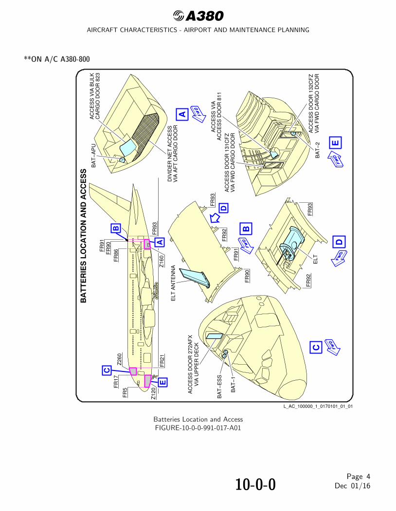
@A380AIRCRAFT CHARACTERISTICS - AIRPORT AND MAINTENANCE PLANNING
**ON A/C A380-800
AC
CE
SS
VIA
AC
CE
SS
DO
OR
131
CF
Z
AC
CE
SS
DO
OR
811
VIA
FW
D C
AR
GO
DO
OR
AC
CE
SS
DO
OR
132
CF
ZV
IA F
WD
CA
RG
O D
OO
RB
AT
−2
AA
CC
ES
S D
OO
R 2
72A
FX
VIA
UP
PE
R D
EC
K
BA
T−
1
BA
T−
ES
S
BA
T−
AP
UA
CC
ES
S V
IA B
ULK
CA
RG
O D
OO
R 8
23
DIV
IDE
R N
ET
AC
CE
SS
VIA
AF
T C
AR
GO
DO
OR
B
ELT
FR
93F
R92
FR
17F
R86
FR
91
FR
5
FR
93
FR
90 A
C
DE
BC
E
FR
91
FR
92
FR
90
FR
93
D
ELT
AN
TE
NN
A
Z12
0
Z16
0F
R21
Z26
0
L_AC_100000_1_0170101_01_01
Batteries Location and AccessFIGURE-10-0-0-991-017-A01
10-0-0Page 4
Dec 01/16

@A380AIRCRAFT CHARACTERISTICS - AIRPORT AND MAINTENANCE PLANNING
**ON A/C A380-800
L_AC_100000_1_0160101_01_00
Crew Rest Compartments LocationFIGURE-10-0-0-991-016-A01
10-0-0Page 5
Dec 01/16

@A380AIRCRAFT CHARACTERISTICS - AIRPORT AND MAINTENANCE PLANNING
**ON A/C A380-800
L_AC_100000_1_0140101_01_00
Wheel/Brake OverheatWheel Safety Area (Sheet 1 of 2)
FIGURE-10-0-0-991-014-A01
10-0-0Page 6
Dec 01/16

@A380AIRCRAFT CHARACTERISTICS - AIRPORT AND MAINTENANCE PLANNING
**ON A/C A380-800
L_AC_100000_1_0140102_01_00
Wheel/Brake OverheatRecommendations (Sheet 2 of 2)
FIGURE-10-0-0-991-014-A01
10-0-0Page 7
Dec 01/16

@A380AIRCRAFT CHARACTERISTICS - AIRPORT AND MAINTENANCE PLANNING
**ON A/C A380-800
L_AC_100000_1_0030101_01_01
Composite Materials LocationFIGURE-10-0-0-991-003-A01
10-0-0Page 8
Dec 01/16

@A380AIRCRAFT CHARACTERISTICS - AIRPORT AND MAINTENANCE PLANNING
**ON A/C A380-800
A
AB
C
B
C
L_AC_100000_1_0040101_01_01
Landing GearGround Lock Safety DevicesFIGURE-10-0-0-991-004-A01
10-0-0Page 9
Dec 01/16

@A380AIRCRAFT CHARACTERISTICS - AIRPORT AND MAINTENANCE PLANNING
**ON A/C A380-800
− 3
− 6
− 9
− 1
2
− 1
5
− 1
8G
RID
EQ
UA
LS 1
m (
3.28
ft)
IN R
EA
LIT
Y
MA
IN D
EC
K D
UA
L−LA
NE
CO
CK
PIT
ES
CA
PE
RO
PE
SLI
DE
/RA
FT
UP
PE
R D
EC
K D
UA
L−LA
NE
SLI
DE
/RA
FT
OV
ER
WIN
G D
UA
L−LA
NE
RA
MP
/SLI
DE
UP
PE
R D
EC
K D
UA
L−LA
NE
SLI
DE
/RA
FT
MA
IN D
EC
K D
UA
L−LA
NE
SLI
DE
/RA
FT
MA
IN D
EC
K D
UA
L−LA
NE
SLI
DE
/RA
FT
UP
PE
R D
EC
K D
UA
L−LA
NE
SLI
DE
/RA
FT
NO
TE
:−
LH
SH
OW
N, R
H S
YM
ME
TR
ICA
L.−
DIM
EN
SIO
NS
AR
E A
PP
RO
XIM
AT
E.
− T
HE
RA
MP
S/S
LID
ES
AT
DO
OR
S M
3L A
ND
M3R
DO
NO
T H
AV
E R
AF
T C
AP
AB
ILIT
Y.
EM
ER
GE
NC
YD
ES
CE
NT
TH
RO
UG
HT
HE
WIN
DO
W O
PE
NIN
GW
ITH
TH
E E
SC
AP
E R
OP
E
L_AC_100000_1_0050101_01_04
Emergency Evacuation DevicesFIGURE-10-0-0-991-005-A01
10-0-0Page 10
Dec 01/16

@A380AIRCRAFT CHARACTERISTICS - AIRPORT AND MAINTENANCE PLANNING
**ON A/C A380-800
L_AC_100000_1_0060101_01_02
Pax/Crew Doors and Emergency ExitsFIGURE-10-0-0-991-006-A01
10-0-0Page 11
Dec 01/16

@A380AIRCRAFT CHARACTERISTICS - AIRPORT AND MAINTENANCE PLANNING
**ON A/C A380-800
132B
R19
9DR
/
5070
JE1
6336
MJ
197C
B
L_AC_100000_1_0070101_01_02
Cargo DoorsFWD and AFT Lower Deck Cargo Doors
FIGURE-10-0-0-991-007-A01
10-0-0Page 12
Dec 01/16

@A380AIRCRAFT CHARACTERISTICS - AIRPORT AND MAINTENANCE PLANNING
**ON A/C A380-800
D
TO
GA
FLX CL 0M C T T H RA
TO
GA
FLX C
L 0M C T T H RA
43
21
1125
VU
OF
F
ON
OF
F
ON
EN
GM
AS
TE
R
OF
F
ON
OF
F
ON
1F
AU
LT
FIR
E
2F
AU
LT
FIR
E
3F
AU
LT
FIR
E
4F
AU
LT
FIR
E
AP
U
CO
CK
PIT
AV
NC
S V
EN
TE
LT
HO
RN
RE
SE
TLI
GH
T T
ES
T
FLT
INT
SV
CE
INT
FIR
E
CA
LLA
PU
SH
UT
OF
F
CA
BIN
PR
ES
S12
15V
M
CA
BIN
ALT
CA
BIN
V/S
A U T O
INC
DE
CA U T O
DN
UP D
ITC
HIN
G
MA
NM
AN
INT
LT
AN
N L
T TE
ST
DIMBR
T
ST
OR
MO
N
OF
F
ST
BY
CO
MP
AS
S
ICE
IND
OF
F
SIG
NS
EM
ER
EX
IT L
T
OF
F
AR
M
ON
OF
F
NO
SM
OK
ING
ON
OF
F
AU
TO
SE
AT
BE
LTS
OF
F
AU
TO
ON
EN
G
12
34
AN
TI I
CE
ON
FA
ULT
ON
FA
ULT
ON
FA
ULT
ON
FA
ULT
ON
FA
ULT
ON
FA
ULT
EX
T L
T
NO
SE
T.O
OF
F
TA
XI
LAN
DO
N
OF
F
RW
Y T
UR
N O
FF
& C
AM
ER
A ON
OF
F
WIN
GO
N
OF
F
LOG
OO
N
OF
F
AU
TO
NA
VO
N
OF
F
BE
AC
ON O
N
OF
F
ST
RO
BE O
N
OF
F
AU
TO
AP
U
EN
G S
TA
RT IG
NS
TA
RT
CR
AN
K
NO
RM
ON
MA
ST
ER
SW
WIN
G
MO
DE
MO
DE
TR
GT
TR
GT
ON
AV
AIL
ST
AR
T
OF
F
FA
ULT
AU
TO
MO
DE
AD
IRS
AD
R3
AD
R2
AD
R1
OF
FA
TT
NA
VO
FF
AT
T
NA
V
OF
FA
TT
NA
V
IR3
IR2
IR1
OF
F
FA
ULT
OF
F
FA
ULT
OF
F
FA
ULT
OF
F
FA
ULT
OF
F
FA
ULT
OF
F
FA
ULT
PR
OB
E/W
IND
OW
HE
AT
A U T OO
N
1221
VM
AG
EN
T
AP
U
DIS
CH
SQ
UIB
FIR
EP
US
H
1245
VM
F I R E
DIS
CH
SQ
UIB
DIS
CH
SQ
UIB
FIR
EF
IRE
FIR
E
DIS
CH
SQ
UIB
DIS
CH
SQ
UIB
DIS
CH
SQ
UIB
DIS
CH
SQ
UIB
DIS
CH
SQ
UIB
FIR
EP
US
H
DIS
CH
SQ
UIB
EN
G 1
EN
G 2
EN
G3
EN
G 4
F I R E
PU
SH
PU
SH
PU
SH
AG
EN
T 1
AG
EN
T 1
AG
EN
T 2
AG
EN
T 2
AG
EN
T 1
AG
EN
T 2
TE
ST
AG
EN
T 1
AG
EN
T 2
1225
VM
AC
ES
S F
EE
DA U T O
A U T OO
N
AV
AIL
ON
AV
AIL
OF
FO
FF
OF
F
FA
ULT
FA
ULT
OF
F
DIS
C
FA
ULT
FA
ULT
OF
FD
ISC
FA
ULT
FA
ULT
OF
F
ALT
N
FA
ULT
ELM
UG
ALL
EY
CO
MM
ER
CIA
L
BU
S T
IEA
C B
US
3A
C B
US
4
E L E C
EX
T 3
EX
T 4
DR
IVE
DR
IVE
GE
NG
EN
AP
U G
EN
B3
4
OF
F
PA
X S
YS
E L E CO
FF
ON
AV
AIL
ON
AV
AIL
OF
F
FA
ULT
OF
F
FA
ULT
OF
F
FA
ULT
OF
F
FA
ULT
DIS
C
FA
ULT
FA
ULT
OF
FD
ISC
FA
ULT
FA
ULT
OF
F
FA
ULT
BA
T 1
ES
S B
AT
BA
T 2
AP
U B
AT
AC
ES
S
AC
BU
S 1
AC
BU
S 2
EX
T 1
EX
T 2
DR
IVE
DR
IVE
GE
NG
EN
OF
F
AP
U G
EN
A1
2
BU
S
OF
F
12
A A
CA
RG
O S
MO
KE
AG
EN
T T
O F
WD
AG
EN
T T
O A
FT
TE
ST
F/C
TL
1212
VM
SE
C 2
PR
IM 2
OF
F
FA
ULT
OF
F
FA
ULT
DIS
CH
SM
OK
E
DIS
CH
SM
OK
EB
TL
1
BT
L 2
CA
RG
O A
IR C
ON
DB
ULK
ISO
L V
ALV
ES
FA
ULT
OF
F
HE
AT
ER
FA
ULT
OF
F
525
TE
MP
RE
GU
L15
AF
T
ISO
L V
ALV
ES
OF
F
FA
ULT
FW
D
ISO
L V
ALV
ES
525
TE
MP
RE
GU
L15
OF
F
FA
ULT
OF
F
VE
NT
AV
NC
SA
VN
CS
EX
TR
AC
T
A U T O
CA
B F
AN
SC
OO
LG
SM
OK
E
OF
F
FA
ULT
OF
FO
VR
D
FA
ULT
A U T O
EN
GM
AN
ST
AR
T
1
23
4
ON
ON
ON
ON
WIP
ER
SLO
W
FA
ST
OF
FR
AIN
RP
LNT
B E
C
BC
DE
HI L
VL
HI L
VL
AP
U E
ME
RG
EN
CY
INC
RE
AS
E
DE
CR
EA
SE
PR
ES
ELE
CT
PR
ES
ELE
CT
(P
FQ
)
OV
ER
FLO
WF
AU
LT
SH
UT
OF
FT
ES
T
NO
RM
AL
BA
TT
ER
Y
PO
WE
R S
UP
PLY
AC
TU
AL
(FO
B)
ST
AT
US
MA
NR
EF
UE
L
XF
R
DE
FU
EL
AU
TO
RE
FU
EL
OF
F
MO
DE
SE
LEC
T
FE
ED
1
FE
ED
1
L O
UT
R
L O
UT
R
R M
ID
OP
EN
SH
UT
R M
ID
R IN
R
R IN
R
TR
IM
TR
IM
L IN
R
L IN
R
L M
ID
L M
ID
R O
UT
RO
PE
N
SH
UT
R O
UT
R
FE
ED
4
FE
ED
4
FE
ED
3
FE
ED
3
FE
ED
2
FE
ED
2
SH
UT
DO
WN
RE
FU
EL/
DE
FU
EL
VA
LVE
S
kg
L_AC_100000_1_0100101_01_01
Control PanelsFIGURE-10-0-0-991-010-A01
10-0-0Page 13
Dec 01/16

@A380AIRCRAFT CHARACTERISTICS - AIRPORT AND MAINTENANCE PLANNING
**ON A/C A380-800
A
A
FR
112
FR
117
315A
L
315A
R
L_AC_100000_1_0110101_01_01
APU Compartment AccessFIGURE-10-0-0-991-011-A01
10-0-0Page 14
Dec 01/16

@A380AIRCRAFT CHARACTERISTICS - AIRPORT AND MAINTENANCE PLANNING
**ON A/C A380-800
F1
BF
2B
F1
C1
CP
1R
D1
M1
F2
M2
U1
M3
U2
M4
U3
F3
C3
M5
HT
1H
TV
T
W1
W2
N2
N1
RF
T1
FT
2F
T3
FT
4F
T5
NO
TE
:P
AS
SE
NG
ER
AN
D C
AR
GO
DO
OR
GR
OU
ND
CLE
AR
AN
CE
S A
RE
ME
AS
UR
ED
FR
OM
TH
E C
EN
TE
R O
F T
HE
DO
OR
SIL
L A
ND
FR
OM
FLO
OR
LE
VE
L.
DO
OR
SA/C
CO
NF
IGU
RA
TIO
Nm
ftM
1M
2M
3M
4
U1
U2
U3
5.36
5.34
5.31
5.28
5.27
8.08
8.04
17.5
917
.52
17.4
217
.32
17.2
926
.51
26.3
8
TA
ILP
LAN
E9.
207.
6524
.17
30.1
825
.10
79.3
0
HT
HT
1V
T
FU
SE
LAG
E
A/C
CO
NF
IGU
RA
TIO
Nm
ftF
1F
2F
3B
F1
BF
2C
P1
RD
1
2.59
11.0
010
.93
1.82
2.38
7.42
5.02
8.50
36.0
935
.86
5.97
7.81
24.3
416
.47
EN
GIN
E/
NA
CE
LLE
1.30
2.27
4.27
7.45
N1
N2
A/C
CO
NF
IGU
RA
TIO
N
WIN
GS
mft
FT
1F
T2
FT
3F
T4
W1
W2 R
3.26
4.31
4.93
5.34
8.22
5.94
1.65
10.7
014
.14
16.1
717
.52
26.9
719
.49
5.41
300
000
kg(6
61 3
87 lb
)A
FT
CG
(44
%)
300
000
kg(6
61 3
87 lb
)A
FT
CG
(44
%)
300
000
kg(6
61 3
87 lb
)A
FT
CG
(44
%)
C1
C2
C3
8.02
3.30
3.23
26.3
110
.83
10.6
03.
3611
.02
M5
FT
55.
6118
.41
C2
L_AC_100000_1_0120101_01_02
Aircraft Ground ClearancesFIGURE-10-0-0-991-012-A01
10-0-0Page 15
Dec 01/16

@A380AIRCRAFT CHARACTERISTICS - AIRPORT AND MAINTENANCE PLANNING
**ON A/C A380-800
L_AC_100000_1_0130101_01_02
Structural Break-in PointsFIGURE-10-0-0-991-013-A01
10-0-0Page 16
Dec 01/16